interface for data exchange between mnos and the utm
TRANSCRIPT

Interface for Data Exchange between
MNOs and the UTM Ecosystem
NetworkCoverage Service Definition v1.00
February 2021

Change History
Date Version Author/Comments
04/02/2021 1.0 ACJA, GSMA and GUTMA approved version
3
1. Contents 2. Introduction ................................................................................................................. 5
2.1. Overview ................................................................................................................... 5
2.2. Scope ........................................................................................................................ 6
2.3. Background, Principles, References ......................................................................... 7
2.3.1. General principles and research basis ......................................................................... 7
2.4. Definitions of Acronyms and Terms .......................................................................... 7
2.4.1. List of Acronyms .......................................................................................................... 7
2.4.2. Terminology ............................................................................................................... 10
2.5. References .............................................................................................................. 13
3. Operational Context ................................................................................................. 15
3.1. Planning Phase ....................................................................................................... 15
3.2. Flight Phase ............................................................................................................ 15
3.3. Example Use Case ................................................................................................. 16
3.4. Additional Definitions ............................................................................................... 17
3.4.1. Operational Nodes ..................................................................................................... 17
3.4.2. Operational Activities ................................................................................................. 18
4. Service Interfaces ..................................................................................................... 19
5. Service Interface Specifications .............................................................................. 20
5.1. Network Coverage Service Interface ....................................................................... 20
5.1.1. Operation getVolumeCoverage.................................................................................. 20
5.1.2. Operation downloadCoverageData ............................................................................ 20
5.1.3. Operation analyzeOperationPlan ............................................................................... 20
5.2. Subscription Interface ............................................................................................. 21
5.2.1. Operation Subscribe .................................................................................................. 21
5.2.2. Operation Unsubscribe .............................................................................................. 21
5.3. Notification Interface ............................................................................................... 21
5.3.1. Operation volumeCoverageChanged ......................................................................... 21
6. Service Dynamic Behavior ....................................................................................... 22
7. Service Data Model ................................................................................................... 23
7.1. The OperationPlan Data Structure .......................................................................... 24
7.2. The Pose Data Structure ......................................................................................... 25

4
7.3. The OperationPlanAnalyzeResult Data Structure ................................................... 26
7.4. The CellRadioParameters Data Structure ............................................................... 27
7.5. The PhysicalAntenna Data Structure ...................................................................... 27
7.6. The ConnectivityProvider Data Structure ................................................................ 28
7.7. The Cell4GConnectivityProvider Data Structure ..................................................... 28
7.8. The RadioParameters Data Structure ..................................................................... 29
7.9. The CoverageData Structure .................................................................................. 29
7.10. The CoverageDataRef Structure ............................................................................. 30
7.11. The Volume Structure ............................................................................................. 31

5
2. Introduction 2.1. Overview
In order to enable Beyond Visual Line Of Sight (BVLOS) operations at scale, drones need reliable
connectivity. To ensure that flight planning can include information on where such connectivity is
available, additional data from connectivity providers is required.
Figure 1 - Operational model diagram
In order to benefit from the fact that cellular networks are utilizing managed spectrum, some
communication must be established between the manager of the spectrum (the mobile network
operator, “MNO”) and the consumer of such data (the aviation operator and/or traffic manager).
In general, digital data from connectivity providers, becoming Supplemental Data Service Providers1,
can support a drone operator’s risk management.
In particular, for safety it is necessary to understand where cellular coverage is available to support
the needs of the mission. “Coverage2” implies a range of requirements such as signal level,
interference, dynamic handover/switchover behavior and others to enable a minimum connectivity
performance along a flight route in a technology and spectrum independent manner.
Presently, BVLOS flights using cellular Command and Control (C2) must only be conducted after a
manual process has been performed to assess coverage. This process is difficult with current data
sharing limitations held by the MNOs. In order to scale, it is necessary to automatically exchange
data between MNOs and USS (UAS Service Supplier) or the respective UAS operator.
There are some products and efforts in the market along these lines. However, there is a lot of
diversity regarding vendors and eco-system players on the market. Pairwise integration would be
slow, laborious, and error-prone. Therefore, standard APIs are recommended as a means to enable
the market, promote inter-vendor interoperability, and ease reliable integration.
Such coverage and flight path exchange are crucial to arrive at performance-based communication
metrics and should assist regulators in defining the role of cellular in aviation.
This document describes a general architecture comprising stakeholders, services, interfaces and
data models. The NetworkCoverage Service provides three-dimensional (actually four-dimensional,
1 Third party information provided by a Supplementary Data Service Providers (SDSP) increases knowledge of the operational flight area for a UAV with data and analysis delivered using web services.
2 “Coverage” for an MNO is also a synonym for “signal availability”, whereas in aviation terms it is typically a combination of sufficient availability, continuity, latency and integrity [19].
6
as it also changes over time) information about data connectivity conditions along a flight route or in
an area of interest. It provides information where connectivity conditions are, or are not, good enough
for safe and reliable data connectivity that adheres to a certain service level, provided by individual
connectivity providers.
2.2. Scope
The NetworkCoverage Service described in this document provides a general mechanism between
the various stakeholders, interfaces and data models that enable and allow the automated data
exchange between the respective parties.
The scope includes the following aspects:
• Operational Context
• Service Interfaces
• Service Interface Definition
• Service Dynamic Behavior
• Service Data Model
There are a number of goals defined that this paper aims to achieve:
1. A goal is to define logical messaging that might be exchanged between a traffic management
system (or drone operator, USS/USSP or equivalent) and an MNO.
2. A goal is to identify architectures that will be amenable to expedient implementation by a
variety of MNOs, given that MNOs have various operating procedures and means of
managing their networks.
3. A goal is to identify architectures that would support a variety of business models and data
sharing models in a technology independent way (i.e. limiting and avoiding exchange of
proprietary and/or sensitive data).
4. A goal is to provide coverage information primarily for C2 but also for payload traffic.
5. A goal is to maintain synchronization with other ACJA Work Tasks, such that the entirety
provides regulators and users with confidence on performance-based requirements.
6. A goal is to organize those needs that require standards input from ASTM, 3GPP or other
standards developing organizations (SDO) to help close the gap between standards orgs.
For example, flight plans may come from ASTM but Key Performance Indicator (KPI) analysis
methods may come from 3GPP, EUROCAE and RTCA.
7. A goal is to understand what real time metrics, non-real time and aggregated data can come
from the MNO, such as, but not limited to, population density, which could be useful in
predicting risk and/or performance-based metrics.
The overall objective is to provide a minimum set of descriptions to standardize the way data
between MNOs and the UTM ecosystem can be exchanged. The NetworkCoverage Service does

7
not limit any entity, by any means, to deploy or implement other data exchange in addition to the
defined service definitions.
This document is not anticipated to be a complete set of functions and definitions for an
implementable API.
This service specification is intended to be read by service architects, system engineers and
developers in charge of designing and developing an instance of the NetworkCoverage Service.
2.3. Background, Principles, References
The fact that ensuring robust communications is essential for safe drone operations is not new.
Other projects and papers have been looking into that extensively.
For example, the CORUS Project [2] identifies a so-called Communication Coverage information
service (see CORUS ConOps Volume 2, chapter 5.1.7.6).
This service is described there as "The service to provide information about the communication
coverage. It can be specialized depending on the communication infrastructure available (e.g.
ground or satellite based). This service is used to plan relying on required coverage."
The CORUS consortium and other references [13] depict the service as U-space3 level 2 service,
likely to be available mid-future.
2.3.1. General principles and research basis
A key principle of the U-spaces architecture is applying a service-oriented architecture approach,
where open, interoperable and standard based interfaces are offered based on SWIM principles4.
This document is based on both research and commercial environments outlined in a range of
references such as [1], [2], [3], [4], [5], [6], [7], [8], [9], [10], [11], [12], [13], [14], [18], [19], [20].
2.4. Definitions of Acronyms and Terms
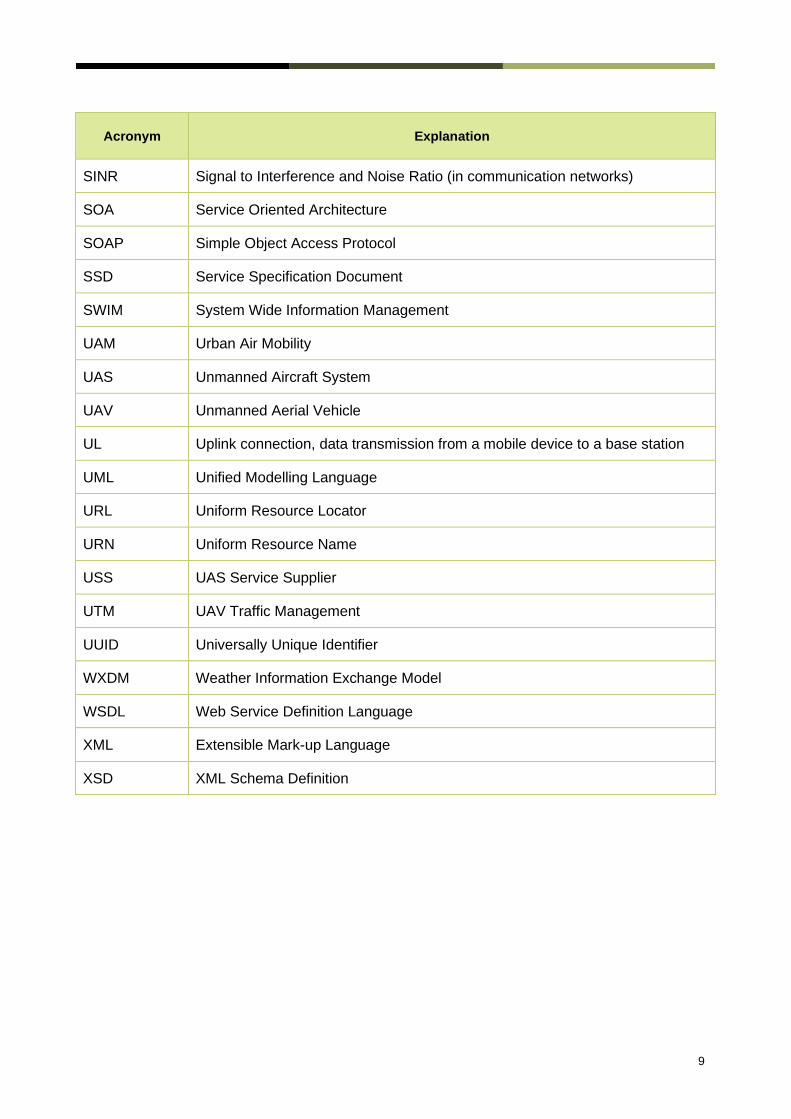
2.4.1. List of Acronyms
Acronym
Explanation
3GPP 3rd Generation Partnership Project
ACJA Aerial Connectivity Joint Activity (by GSMA + GUTMA)
AIXM Aeronautical Information Exchange Model
AMQ Advanced Message Queuing
3 U-space is a set of new services relying on a high level of digitalization and automation of functions and specific procedures designed to support safe, efficient and secure access to airspace for large numbers of drones in Europe [2].
444 Note that by SWIM principles the general concept including not only AIXM, FIXM, WIXM via SOAP are meant, but also web services / rest / messaging (JMS, AMQ) as considered in the SWIM Yellow profile [4].

8
Acronym
Explanation
API Application Programming Interface
ASTM American Society for Testing and Materials
ATM Air Traffic Management
BVLOS Beyond Visual Line of Sight
C2 Command and Control
CIS Common Information Service
CTR Controlled Traffic Region
DL Downlink connection, data transmission from a base station to a mobile device
DSS Discovery and Synchronization Service
EDT Estimated Time of Departure
FIXM Flight Information Exchange Model
FPL Flight Plan
GSM Global System for Mobile Communication
GSMA GSM Association
GUTMA Global UTM Association
JMG Java Message Service
KPI Key Performance Indicator
MEP Message Exchange Pattern
MNO Mobile Network Operator
NAF NATO Architectural Framework
NOTAM Notice To Air Man
REST Representational State Transfer
RF Radio Frequency
RSRP Reference Signal Received Power
SDO Standards Developing Organization
9
Acronym
Explanation
SINR Signal to Interference and Noise Ratio (in communication networks)
SOA Service Oriented Architecture
SOAP Simple Object Access Protocol
SSD Service Specification Document
SWIM System Wide Information Management
UAM Urban Air Mobility
UAS Unmanned Aircraft System
UAV Unmanned Aerial Vehicle
UL Uplink connection, data transmission from a mobile device to a base station
UML Unified Modelling Language
URL Uniform Resource Locator
URN Uniform Resource Name
USS UAS Service Supplier
UTM UAV Traffic Management
UUID Universally Unique Identifier
WXDM Weather Information Exchange Model
WSDL Web Service Definition Language
XML Extensible Mark-up Language
XSD XML Schema Definition

10
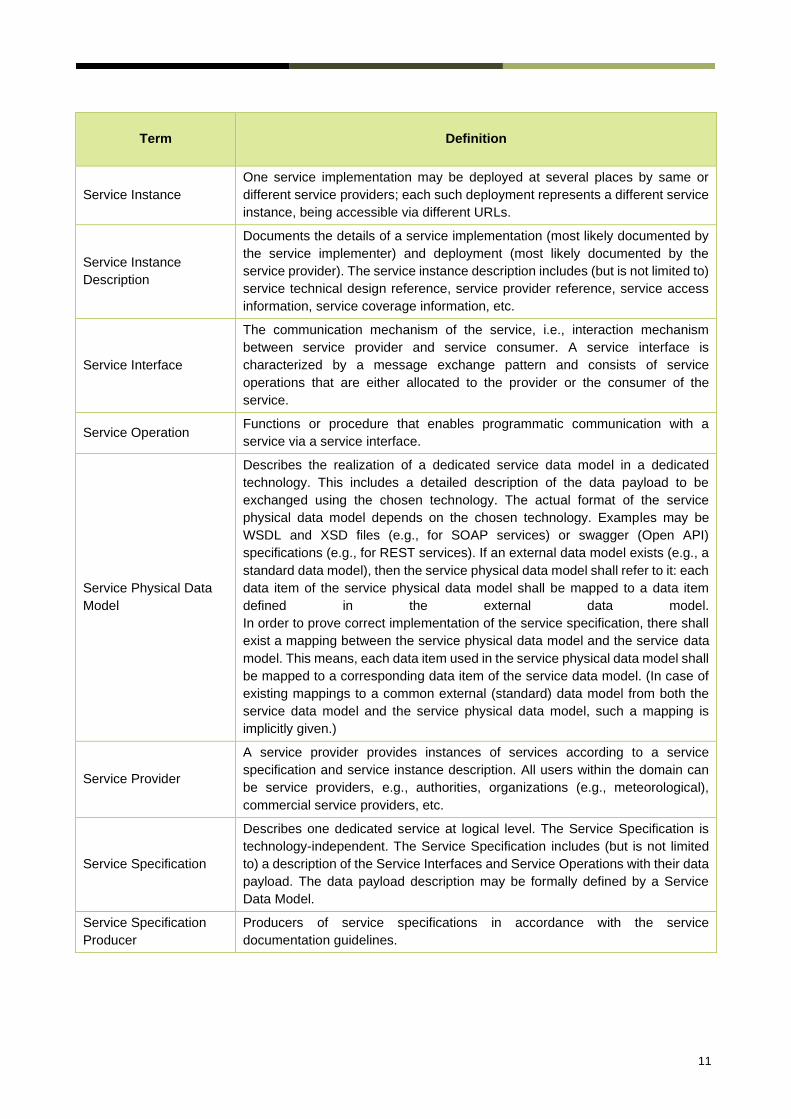
2.4.2. Terminology
Term
Definition
External Data Model
Describes the semantics of the domain (or a significant part thereof) by defining
data structures and their relations. This could be at logical level (e.g., in UML) or
at physical level (e.g., in XSD schema definitions), as for example standard data
models.
Message Exchange
Pattern
Describes the principles how two different parts of a message passing system
(i.e.: the service provider and the service consumer) interact and communicate
with each other. Examples:
In the Request/Response MEP, the service consumer sends a request to the
service provider in order to obtain certain information; the service provider
provides the requested information in a dedicated response.
In the Publish/Subscribe MEP, the service consumer establishes a subscription
with the service provider in order to obtain certain information; the service
provider publishes information (either in regular intervals or upon change) to all
subscribed service consumers.
Operational Activity
An activity performed by an operational node. Examples of operational activities
are: Route Planning, Route Optimization, Logistics, Safety, Weather Forecast
Provision, …
Operational Model A structure of operational nodes and associated operational activities and their
inter-relations in a process model.
Operational Node
A logical entity that performs activities. Note: nodes are specified
independently of any physical realization. Examples of operational nodes are:
Control Center, Authority, Weather Information Provider
Service
The provision of something (a non-physical object), by one, for the use of one or
more others, regulated by formal definitions and mutual agreements. Services
involve interactions between providers and consumers, which may be performed
in a digital form (data exchanges) or through voice communication or written
processes and procedures.
Service Consumer A service consumer uses service instances provided by service providers.
Service Data Model
Formal description of one dedicated service at logical level. The service data
model is part of the service specification. Is typically defined in UML and/or XSD.
If an external data model exists (e.g., a standard data model), then the service
data model shall refer to it: each data item of the service data model shall be
mapped to a data item defined in the external data model.
Service Design
Description
Documents the details of a service technical design (most likely documented by
the service implementer). The service design description includes (but is not
limited to) a service physical data model and describes the used technology,
transport mechanism, quality of service, etc.
Service Implementation The provider side implementation of a dedicated service technical design (i.e.,
implementation of a dedicated service in a dedicated technology).
Service Implementer Implementers of services from the service provider side and/or the service
consumer side.
11
Term
Definition
Service Instance
One service implementation may be deployed at several places by same or
different service providers; each such deployment represents a different service
instance, being accessible via different URLs.
Service Instance
Description
Documents the details of a service implementation (most likely documented by
the service implementer) and deployment (most likely documented by the
service provider). The service instance description includes (but is not limited to)
service technical design reference, service provider reference, service access
information, service coverage information, etc.
Service Interface
The communication mechanism of the service, i.e., interaction mechanism
between service provider and service consumer. A service interface is
characterized by a message exchange pattern and consists of service
operations that are either allocated to the provider or the consumer of the
service.
Service Operation Functions or procedure that enables programmatic communication with a
service via a service interface.
Service Physical Data
Model
Describes the realization of a dedicated service data model in a dedicated
technology. This includes a detailed description of the data payload to be
exchanged using the chosen technology. The actual format of the service
physical data model depends on the chosen technology. Examples may be
WSDL and XSD files (e.g., for SOAP services) or swagger (Open API)
specifications (e.g., for REST services). If an external data model exists (e.g., a
standard data model), then the service physical data model shall refer to it: each
data item of the service physical data model shall be mapped to a data item
defined in the external data model.
In order to prove correct implementation of the service specification, there shall
exist a mapping between the service physical data model and the service data
model. This means, each data item used in the service physical data model shall
be mapped to a corresponding data item of the service data model. (In case of
existing mappings to a common external (standard) data model from both the
service data model and the service physical data model, such a mapping is
implicitly given.)
Service Provider
A service provider provides instances of services according to a service
specification and service instance description. All users within the domain can
be service providers, e.g., authorities, organizations (e.g., meteorological),
commercial service providers, etc.
Service Specification
Describes one dedicated service at logical level. The Service Specification is
technology-independent. The Service Specification includes (but is not limited
to) a description of the Service Interfaces and Service Operations with their data
payload. The data payload description may be formally defined by a Service
Data Model.
Service Specification
Producer
Producers of service specifications in accordance with the service
documentation guidelines.

12
Term
Definition
Service Technical
Design
The technical design of a dedicated service in a dedicated technology. One
service specification may result in several technical service designs, realizing
the service with different or same technologies.
Service Technology
Catalogue
List and specifications of allowed technologies for service implementations.
Currently, SOAP and REST are envisaged to be allowed service technologies.
The service technology catalogue shall describe in detail the allowed service
profiles, e.g., by listing communication standards, security standards, stacks,
bindings, etc.
Spatial Exclusiveness
A service specification is characterized as "spatially exclusive", if in any
geographical region just one service instance of that specification is allowed to
be registered per technology.
The decision, which service instance (out of a number of available spatially
exclusive services) shall be registered for a certain geographical region, is a
governance issue.

13
2.5. References
[1] 3GPP – "Enhanced LTE support for aerial vehicles", RR 35.777, Release 15, 2019, "http://www.3gpp.org" www.3gpp.org
[2] CORUS – SESAR "Concept of Operations for U-Space", https://www.sesarju.eu/node/3411
[3] 5G!Drones, "Initial Definition of the trial controller architecture, mechanisms and APIs", 2020 https://5gdrones.eu/wp-content/uploads/2020/06/D2.1-Initial-definition-of-the-trial-controller-architecture-mechanisms-and-APIs_v1.1.pdf
[4] SESAR – SWIM Profiles, 2015, https://www.sesarju.eu/sites/default/files/SESAR-Factsheet-2015-SWIM-Profiles.pdf
[5] DroC2om – Drone Critical Communications Project, including C2 for U-Space via combined cellular and satellite systems, https://www.droc2om.eu/
[6] U-Space DREAMS (Drones European Aims Study) Final Project Results Report, 2019, https://www.u-spacedreams.eu/wp-content/uploads/ER-DREAMS-D2.2-U-space-Final-Project-Results-Report_1.1.pdf
[7] FAA – UAS Identification and Tracking – Aviation Rulemaking Committee (ARC) Final Report, 2017, https://www.faa.gov/regulations_policies/rulemaking/committees/documents/media/UAS%20ID%20ARC%20Final%20Report%20with%20Appendices.pdf
[8] European Commission, "SESAR Standardisation Roadmap 2020", 2019, https://ec.europa.eu/research/participants/documents/downloadPublic?documentIds=080166e5c9ec6a75&appId=PPGMS
[9] SESAR - "GOF USPACE - Successful demonstration of UTM in international validations, applying SWIM principles to connect 2 air navigation service providers and 3 U-space service provider", 2019 https://www.sesarju.eu/node/3387
[10] ICAO, "International work on high level standardisation of information exchange", https://www.icao.int/APAC/Pages/swim.aspx
[11] EU Commission – "IMPETUS (Information Management Portal to Enable the Integration of Unmanned Systems) - Architecture and Technical Requirements", 2019, https://ec.europa.eu/research/participants/documents/downloadPublic?documentIds=080166e5c1c8fa04&appId=PPGMS
[12] SESAR - EMPHASIS, "Empowering heterogeneous aviation through cellular signals", 2020, https://www.sesarju.eu/node/3109
[13] SESAR – “Consolidated Report on SESAR U-Space Research and Innovations Results”, Nov 2020, https://www.sesarju.eu/node/3691

14
[14] ICAO – “Technology Workshop ICAO RPAS MANUAL C2 Link and Communications”, 2015, https://www.icao.int/Meetings/RPAS/RPASSymposiumPresentation/Day%202%20Workshop%205%20Technology%20Michael%20Neale%20-%20ICAO%20RPAS%20Manual%20C2%20Link%20and%20Communications.pdf
[15] Open Geospatial Consortium, “OGC GeoTIFF standard”, http://docs.opengeospatial.org/is/19-008r4/19-008r4.html
[16] FAA, UTM Concept of Operations v2.0, March 2020, https://www.faa.gov/uas/research_development/traffic_management/media/UTM_ConOps_v2.pdf
[17] European Commission, Annex to EASA Opinion No 01/2020, “Commission Implementing Regulation (EU), DRAFT”, Oct 2020, https://www.easa.europa.eu/sites/default/files/dfu/Draft%20COMMISSION%20IMPLEMENTING%20REGULATION%20on%20a%20high-level%20regulatory%20fram....pdf
[18] ASTM F3411-19, “Standard Specification for Remote ID and Tracking”, Committee F38 on Unmanned Aircraft Systems, https://www.astm.org/COMMITTEE/F38.htm
[19] RTCA DO-377, “Minimum Aviation System Performance Standards for C2 Link Systems Supporting Operations of Unmanned Aircraft Systems in U.S. Airspace”, https://standards.globalspec.com/std/13301563/rtca-do-377, March 2019
[20] EUROCAE ED-269, “Minimum Operational Performance Standard for Geofencing”, www.eurocae.net, June 2020

15
3. Operational Context
Safe operation of UAS / UAM may likely require knowledge of expected RF communications link
quality (performance) and coverage during planning and flight operation, as well as measurement
and monitoring of these parameters during the flight.
Communication coverage is not static information and is subject to continuous change due to a
multitude of factors. Consequently, the coverage information comprises real-time and non-real-time
data. Real-time data may include live performance indicators, alerts on significant changes, but also
real-time network outage information. Non-real-time data for instance could include, but is not limited
to, aggregated and historic information as well as planned events (such as planned maintenance
outages of the network), which allows connectivity analytics and projections into the future. Both
types of data complement each other.
3.1. Planning Phase
Before the start of a flight, there may likely be a need to determine how the planned flight path or flight operations area fits into the following geographic areas:
• Areas with or without cellular network coverage.
• Areas where non-cellular RF coverage is bad or non-existent, either due to atmospheric conditions, terrain/building obstruction, or others.
These factors can be determined via network / surveillance coverage maps, RF propagation modeling, as well through public space weather services. Deriving the necessary OK/not-OK information will require automated processing and data exchange.
3.2. Flight Phase
During a flight, adherence to the flight plan needs and limitations to be monitored, and any non-conformance outside of pre-established thresholds and safety margins defined in the operational authorization, should trigger appropriate mitigation actions.
In addition, UTM service providers receive data about the link quality between UAV and ground station / pilot, measuring current signal strength, cumulative signal strength, data transmission latency, number of packet retransmissions, network notifications, etc.
This data indicates the real time link quality and may be used to react to possible deterioration of link quality, or even a complete loss of link. Although the safety criticality of the C2 link depends on characteristics of the UA and the contingency procedures proposed by a UAV operator, some UAV may pose a safety risk in case of C2 outage time beyond the expected availability as they are essentially uncooperative drones that do not respond to commands until link is reestablished.

16
3.3. Example Use Case
An example service use is shown in Figure 1 and described in more detail below:
Figure 1 - Operational model diagram
• A UAV operator wants to fly a mission from A to B.
• In order to estimate the general feasibility of the flight, among other things, the connectivity situation in the general area of the flight must be checked by the Operation Planning Service5. The Communication Provider provides the area coverage information utilizing the NetworkCoverage Service.
• If the flight is feasible in a given area, a concrete route must be planned. Considering among others the weather, airspace restrictions, aircraft performance, etc., one or more route candidates are created by the drone operator (and/or USS/USSP or equivalent), which are checked with the support of the NetworkCoverage Service whether the minimum service level (for example: continuous C2 availability) is met along the candidate routes. If requested, the NetworkCoverage Service can also propose alternate routes to assure the minimum service level of the connectivity.
• The drone operator prepares a flight intent plan ahead of ETD in line with the operational limitations of his/her authorization. The operator can be assisted in this task by the Operation Planning Service which may coordinate with the NetworkCoverage Service if the planned flight route meets the minimum service level requirements.
• Shortly before the flight actually commences, the Operation Planning Service may recheck that the connectivity service level requirements are still met (together with meteorology,
5 "Operational Planning" is derived from the FAA UTM Conops v2.0 section 2.4.4 [16]: "The Operation Planning service supports the
operator to define prior to the operation a four-dimensional (4D) volume of airspace within which the operation is expected to occur, the times and locations of the key events associated with the operation, including launch, recovery, and any other information deemed important (e.g., segmentation of the operation trajectory by time)."

17
NOTAMs, etc.), and, where necessary, alternate routes can be proposed. Then, clearance is requested from Flight/Airspace Authorization Service6 to commence the flight.
• During the flight, due to an outage at the communication provider, a certain segment of the flight planned route ahead of the aircraft loses connectivity. For this the link quality could be used as key performance indicator. A Connectivity Service at the Communication Provider identifies this situation and informs the Notification Service7 by utilizing the NetworkCoverage Service.
• The drone operator may have to re-plan the rest of the flight, and coordinate the changes using the Operation Planning Services, again with the assistance of the NetworkCoverage Service, to stay on a route that meets the connectivity minimum service level requirements, or apply contingency/emergency procedures in line with the approved Concept of Operations.
Providers and actors might / will be different depending on the local legislation/regulations.
3.4. Additional Definitions
3.4.1. Operational Nodes
Operational Node Remarks
Connectivity Provider A provider of communication services like a Mobile Network
Operator or a Satellite Data Communications Provider.
Connectivity Service Service deployed close to mobile network operator
infrastructure, providing connectivity data for the Network
Coverage Service.
Table 1 - Operational Nodes providing the Connectivity Service
Operational Node Remarks
Operation Planning
Service
Service defined in FAA UTM Conops v2.0 section 2.4.4 [16]:
"The Operation Planning service supports the operator to
define prior to the operation a four-dimensional (4D) volume
of airspace within which the operation is expected to occur,
the times and locations of the key events associated with the
operation, including launch, recovery, and any other
information deemed important (e.g., segmentation of the
operation trajectory by time).
6 This service is called "Airspace Authorization" service in FAA UTM Conops v2 section 2.4.3 [16] and "Flight Authorisation" in EASA draft Commission U-Space regulation in Europe, Article 12 [17].
7 The Notification Service may provide such information to the “Constraint Information & Advisories” Service as defined in the FAA ConOps v2.0, Section 2.4.5 [16] or equivalent. Similarly, in the SESAR CORUS “U-Space Concept of Operations” [2] there are services defined in sections 5.1.5.1 and 5.1.6.6 that require “… to provide status information about communication infrastructure. … The service should give warnings of degradation of communications infrastructure”.

18
Flight/Airspace
Authorization Service
Service providing authorization for a specific flight.
Depending on local regulation this service works with flight
trajectories or airspace volumes.
Notification Service Notifies drone operators of relevant changes that occurred
typically in-flight, or pre-flight after the initial planning phase.
It could consume events from different services, not only the
Network Coverage Service.
Table 2 - Operational Nodes (directly) consuming the Connectivity Service
3.4.2. Operational Activities
Operational Activity Remarks
Get area and flight route
coverage
Returns information about connectivity coverage for a certain
area or flight route for a particular technology and
communication provider for a particular time period in the
future.
Notify about changes in
coverage
For a given area or flight route, get notifications about
changes to connectivity.
Provide communication
services
The communication provider provides its infrastructure to the
drone operators for data communication.
Table 3 – Operational Activities supported by the NetworkCoverage service

19
4. Service Interfaces
The following diagram depicts the Service Interfaces of the NetworkCoverage Service, and their allocations to the Service Provider and the Service Consumers, respectively:
Figure 2 - Connectivity Service Interface Definition Diagram
ServiceInterface Role (from service provider point of view)
ServiceOperation
NetworkCoverageServiceInterface Provided getVolumeCoverage downloadCoverageData analyzeOperationPlan
NetworkCoverageSubscriptionInterface Provided subscribe unsubscribe
NetworkCoverageServiceNotificationInterface Required volumeCoverageChanged
Table 4 - Service Interfaces
20
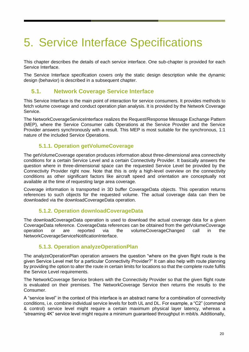
5. Service Interface Specifications
This chapter describes the details of each service interface. One sub-chapter is provided for each Service Interface.
The Service Interface specification covers only the static design description while the dynamic design (behavior) is described in a subsequent chapter.
5.1. Network Coverage Service Interface
This Service Interface is the main point of interaction for service consumers. It provides methods to fetch volume coverage and conduct operation plan analysis. It is provided by the Network Coverage Service.
The NetworkCoverageServiceInterface realizes the Request/Response Message Exchange Pattern (MEP), where the Service Consumer calls Operations at the Service Provider and the Service Provider answers synchronously with a result. This MEP is most suitable for the synchronous, 1:1 nature of the included Service Operations.
5.1.1. Operation getVolumeCoverage
The getVolumeCoverage operation produces information about three-dimensional area connectivity conditions for a certain Service Level and a certain Connectivity Provider. It basically answers the question where in three-dimensional space can the requested Service Level be provided by the Connectivity Provider right now. Note that this is only a high-level overview on the connectivity conditions as other significant factors like aircraft speed and orientation are conceptually not available at the time of requesting large area coverage.
Coverage information is transported in 3D buffer CoverageData objects. This operation returns references to such objects for the requested volume. The actual coverage data can then be downloaded via the downloadCoverageData operation.
5.1.2. Operation downloadCoverageData
The downloadCoverageData operation is used to download the actual coverage data for a given CoverageData reference. CoverageData references can be obtained from the getVolumeCoverage operation or are reported via the volumeCoverageChanged call in the NetworkCoverageServiceNotificationInterface.
5.1.3. Operation analyzeOperationPlan
The analyzeOperationPlan operation answers the question “where on the given flight route is the given Service Level met for a particular Connectivity Provider?” It can also help with route planning by providing the option to alter the route in certain limits for locations so that the complete route fulfils the Service Level requirements.
The NetworkCoverage Service brokers with the Connectivity Provider so that the given flight route is evaluated on their premises. The NetworkCoverage Service then returns the results to the Consumer.
A “service level” in the context of this interface is an abstract name for a combination of connectivity conditions, i.e. combine individual service levels for both UL and DL. For example, a “C2” (command & control) service level might require a certain maximum physical layer latency, whereas a “streaming 4K” service level might require a minimum guaranteed throughput in mbit/s. Additionally,

21
depending on the communication technology, other technical thresholds and limits will be in place for the different service levels (in 4G for example, a minimum RSRP and SINR value). These thresholds and limits are configured on the Connectivity Provider’s side and likely be specified by standardization. The aviation end user (e.g. UAS operator) does not need to know these; it only requests the service levels by name that are relevant for the planned mission.
5.2. Subscription Interface
This Service Interface provides Subscribe operations to Service Consumers. It is provided by the NetworkCoverage Service.
The NetworkCoverageSubscriptionInterface and the NetworkCoverageNotificationInterface together realize the Publisher/Subscriber MEP. As the connectivity information in a certain area constantly changes, the notification for such changes is posted to a Publisher/Subscriber topic. Service Consumers can attach to those topics and get asynchronously notified about changes to areas of their interest.
5.2.1. Operation Subscribe
The subscribe operation allows a Service Consumer to subscribe to changes in area connectivity coverage.
Whenever the connectivity information for a certain Service Level and Connectivity Provider happens to change, a notification is posted in a dedicated topic. Service Consumers can subscribe to that topic to be notified about those changes.
5.2.2. Operation Unsubscribe
As the opposite Operation of subscribe, this Operation allows a Service Consumer to stop receiving notifications about changes for a certain Service Level and Connectivity Provider.
This removes the Service Consumer from the list of Consumers to be notified.
5.3. Notification Interface
This Service Interface is provided by and implemented on the Service Consumer’s side. It is called to notify the Service Consumer about changes it subscribed to via the Operations in the NetworkCoverageSubscriptionInterface.
The NetworkCoverageSubscriptionInterface and the NetworkCoverageNotificationInterface together realize the Publisher/Subscriber MEP. As the connectivity information in a certain area constantly changes, the notification for such changes is posted to a Publisher/Subscriber topic. Service Consumers can attach to those topics and are asynchronously notified about changes to areas of their interest.
5.3.1. Operation volumeCoverageChanged
This Operation is called on the Service Consumer’s side whenever the coverage information for a certain Service Level and a certain Connectivity Provider changed.
Whenever the connectivity information for a certain Service Level and Connectivity Provider happens to change and exceeds specific thresholds, a notification is posted in a dedicated topic. If the Service Consumer subscribed to that topic, it will receive notifications via this Operation.
22
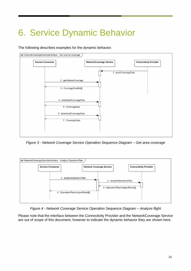
6. Service Dynamic Behavior
The following describes examples for the dynamic behavior.
Figure 3 - Network Coverage Service Operation Sequence Diagram – Get area coverage
Figure 4 - Network Coverage Service Operation Sequence Diagram – Analyze flight
Please note that the interface between the Connectivity Provider and the NetworkCoverage Service are out of scope of this document, however to indicate the dynamic behavior they are shown here.
23
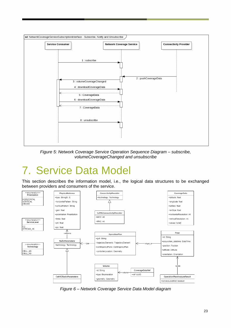
Figure 5: Network Coverage Service Operation Sequence Diagram – subscribe, volumeCoverageChanged and unsubscribe
7. Service Data Model This section describes the information model, i.e., the logical data structures to be exchanged between providers and consumers of the service.
Figure 6 – Network Coverage Service Data Model diagram

24
The Service Data Model focuses on the core service model and the diagram includes structures (OperationPlan, Volume, Pose), whose detailed specification are out of scope of this document.
The data model supports and is compatible with a number of industry standards, such as ICAO, ASTM F3411-19 [18], EUROCAE ED-269 [20], FIXM, etc. It is important to note that the data model can be extended, for example for future requirements and additional information that may need to be exchanged.
The following tables describe the entities and their attributes in more detail.
7.1. The OperationPlan Data Structure
The OperationPlan represents a complete flight plan. It refers to Pose instances providing spatial orientation of the aircraft for positions along the planned flight trajectory.
Note: Selected attributes of the OperationPlan are listed here to provide context for better understanding. For implementation a fully described OperationPlan is to be provided in a separate Operation Plan service specification.
The information about the communication equipment used on the aircraft is provided when requesting a network coverage analysis.
Property Type Multiplicity Description Note
gufi String 1 A gufi: globally unique flight identifier in form of a UUID
More information for a flight could be retrieved using a respective Flight Information Service
trajectoryElements TrajectoryElement 1..*
The positions (locations and orientation in space) that represent the flight route.

25
contingencyPlans ContingencyPlan 0..*
Holds information on preplanned contingency situations, especially regarding volumes and when they are used.
controllerLocation Geometry 0..1 Location of controller (e.g. the ground control station)
radioParameters RadioParameters 0..*
Information about the communication equipment used during the flight.
Table 5 - The Flight data structure
7.2. The Pose Data Structure
The Pose provides a location in space (3D), orientation of an aircraft and time applicable.
Note: Selected attributes are listed here to provide context for better understanding. For implementation a fully described Pose is to be provided in a separate Service Specification.
Property Type Multiplicity Description Note
aquisitionDateTime DateTime 1 UTC point in time when the position was measured by the positioning unit of the device in flight.
For flight planning purposes this will be a time in the future.

26
position Position 1
Carries the position data of the object being reported about in this Pose.
There shall be exactly one position contained in the Pose.
altitude Altitude 1..*
There shall be one or more complete Altitude data structure provided for every Pose. The first of the Altitude data structures provided shall contain the value which subsequent processing stages may rely on as accurate and binding.
orientation Orientation 0..1
If provided, carries the orientation data of the object being reported about in this Pose.
There may be none or one Orientation data structure provided for every Pose, providing all, or a subset, of the data it may carry.
Table 6 - The Pose data structure
7.3. The OperationPlanAnalyzeResult Data Structure
The OperationPlanAnalyzeResult holds an analysis in regards to connectivity coverage for an OperationPlan.
Property Type Multiplicity Description Note
serviceLevelMet boolean 1 Whether the requested service level is met at the given Pose.

27
pose Pose 1 Reference to a Pose instance of an OperationPlan for which the service level was tested.
Table 7 - The OperationPlanAnalyzeResult data structure
7.4. The CellRadioParameters Data Structure
The CellRadioParameters provides communication equipment (physical) and logical communication information for mobile communication.
Property Type Multiplicity Description Note
technology Technology 1 The technology of the radio parameters. Fixed CELL_4G, CELL_5G, ...
... ... List of required attributes is likely subject to change.
Table 8 - The CellRadioParameters data structure
7.5. The PhysicalAntenna Data Structure
The PhysicalAntenna provides information about the physical antenna used for communication on the aircraft. There can be more than one such antennas. The orientation of the antenna on the aircraft is modelled using Euler angles (more specifically, the orientation of the antenna pattern).
Property Type Multiplicity Description Note
type string 0..1
A type specifier of the antenna. Optional; can be used instead of specifying the pattern, gain and polarization attributes if the antenna type is well-known.
horizontalPattern string 1 Horizontal antenna pattern string.
verticalPattern string 1 Vertical antenna pattern string.

28
gain float 1 Antenna gain, in dBi.
polarization Polarization 1 Antenna polarization.
theta, phi, psi float 1 Orientation angles of the antenna.
Table 9 - The PhysicalAntenna data structure
7.6. The ConnectivityProvider Data Structure
The Connectivity Provider represents a connectivity provider, e.g. a provider of communication services like a Mobile Network Operator or a Satellite Data Communication Provider.
Property Type Multiplicity Description Note
technology Technology 1 The technology of the radio parameter.
Table 10 - The ConnectivityProvider data structure
7.7. The Cell4GConnectivityProvider Data Structure
The Cell4GConnectivityProvider is an example specialization of the ConnectivityProvider class. It contains additional attributes to identify a Mobile Network Operator that offers 4G cellular connectivity services.
It works the same for 5G, while for satellite or other connectivity technology providers the attributes might be different.
Property Type Multiplicity Description Note
MCC int 1 Mobile Country Code.
MNC int 1 Mobile Network Code. MCC and MNC together uniquely identify the Mobile Network Operator globally.
Table 11 - The Cell4GConnectivityProvider data structure

29
7.8. The RadioParameters Data Structure
The RadioParameters provides communication equipment (physical) and logical communication information. This is an abstract class, needs technology-aware specialized implementation.
Property Type Multiplicity Description Note
technology Technology 1 The technology of the radio parameters.
antenna Antenna 1 The used antenna parameters.
Table 12 - The RadioParameters data structure
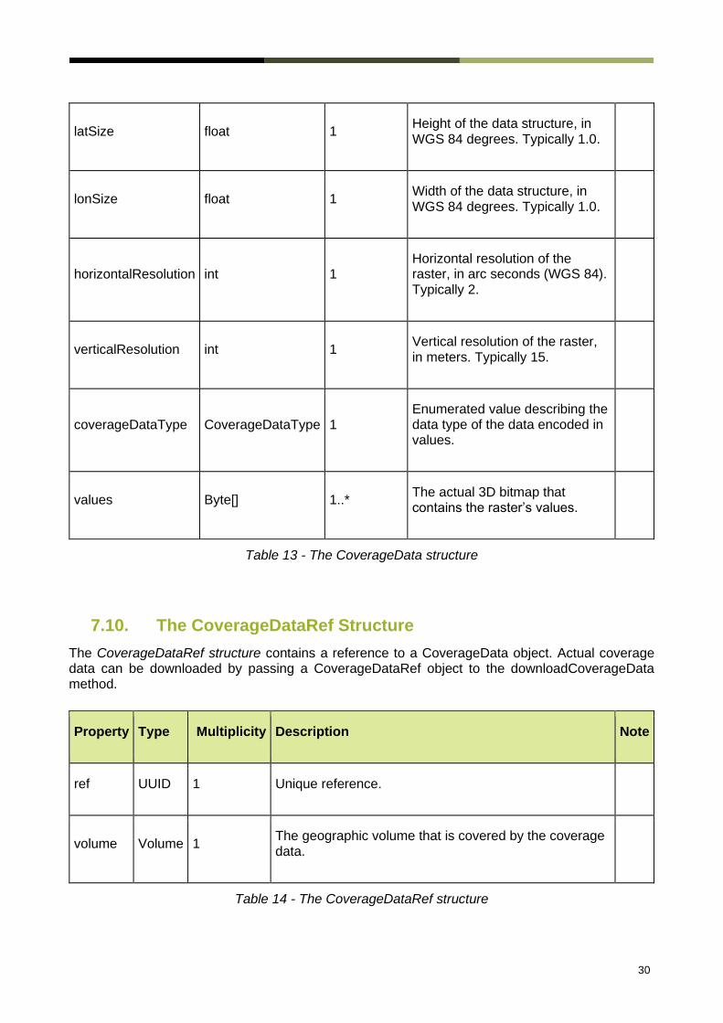
7.9. The CoverageData Structure
The CoverageData structure contains 3D aerial coverage information in a raster of a certain resolution. Full capabilities are to be described in an external CoverageData specification document for further processing.
It is essentially a 3D grid where each grid cell has an assigned a value. CoverageData is like a 3D bitmap, where the pixel content represents attributes relevant for exchanging network coverage information, e.g. boolean values true/false to describe whether the requested service level is met at that particular point or not.
In future versions of this data structure, CoverageData could support exchange of numeric values or other types that can be encoded in a byte, allowing to transport e.g. minimum throughput in a grid cell.
How exactly values are encoded in the byte array has to be described in a separate document specific to and available for an implementation of CoverageData.
Property Type Multiplicity Description Note
latitude float 1 Latitude of the upper-left corner of the area covered in WGS84.
longitude float 1 Longitude of the upper-left corner of the area covered in WGS84.
30
latSize float 1 Height of the data structure, in WGS 84 degrees. Typically 1.0.
lonSize float 1 Width of the data structure, in WGS 84 degrees. Typically 1.0.
horizontalResolution int 1 Horizontal resolution of the raster, in arc seconds (WGS 84). Typically 2.
verticalResolution int 1 Vertical resolution of the raster, in meters. Typically 15.
coverageDataType CoverageDataType 1 Enumerated value describing the data type of the data encoded in values.
values Byte[] 1..* The actual 3D bitmap that contains the raster’s values.
Table 13 - The CoverageData structure
7.10. The CoverageDataRef Structure
The CoverageDataRef structure contains a reference to a CoverageData object. Actual coverage data can be downloaded by passing a CoverageDataRef object to the downloadCoverageData method.
Property Type Multiplicity Description Note
ref UUID 1 Unique reference.
volume Volume 1 The geographic volume that is covered by the coverage data.
Table 14 - The CoverageDataRef structure
31
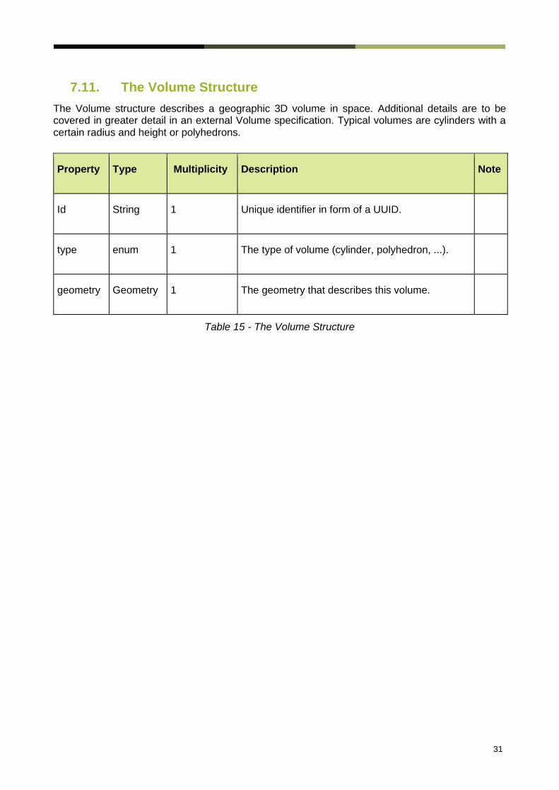
7.11. The Volume Structure
The Volume structure describes a geographic 3D volume in space. Additional details are to be covered in greater detail in an external Volume specification. Typical volumes are cylinders with a certain radius and height or polyhedrons.
Property Type Multiplicity Description Note
Id String 1 Unique identifier in form of a UUID.
type enum 1 The type of volume (cylinder, polyhedron, ...).
geometry Geometry 1 The geometry that describes this volume.
Table 15 - The Volume Structure

About the GSMA
The GSMA represents the interests of mobile
operators worldwide, uniting more than 750
operators and nearly 400 companies in the
broader mobile ecosystem, including handset
and device makers, software companies,
equipment providers and internet companies,
as well as organisations in adjacent industry
sectors. The GSMA also produces the
industry leading MWC events held annually in
Barcelona, Los Angeles and Shanghai, as
well as the Mobile 360 Series of regional
conferences.
For more information, please visit
www.gsma.com
About the GUTMA
The Global UTM Association (GUTMA) is a
non-profit consortium of worldwide
Unmanned Aircraft Systems Traffic
Management (UTM) stakeholders. Its
purpose is to foster the safe, secure and
efficient integration of drones in national
airspace systems. Its mission is to support
and accelerate the transparent
implementation of globally interoperable UTM
systems. GUTMA members collaborate
remotely.
For more information, please visit www.gutma.org