interdisciplinary approach to deformation analysis … · 2007-05-16 · interdisciplinary approach...
TRANSCRIPT

147Interdisciplinary approach to deformation analysis in engineering, mining...TECHNICAL SCIENCESAbbrev.: Tech. Sc., Pap. And Rep., No 9, Y. 2006
INTERDISCIPLINARY APPROACH TO DEFORMATIONANALYSIS IN ENGINEERING, MINING, AND GEOSCIENCES
PROJECTS BY COMBINING MONITORING SURVEYSWITH DETERMINISTIC MODELING
PART I
Anna Szostak-ChrzanowskiDepartment of Geodesy and Geomatics Engineering
Canadian Centre for Geodetic EngineeringUniversity of New Brunswick P.O.
Box 4400 Fredericton, N.B., Canada, E3B 5M2
K e y w o r d s: deformation analysis, integrated monitoring, engineering, mining, finite elementmethod.
A b s t r a c t
This presentation summarizes the authors developments and contributions to theinterdisciplinary approach to integrated deformation analysis in engineering, mining andgeosciences projects by combining monitoring surveys and deterministic analysis (numericalmodeling using finite element method). The combination of monitoring and numerical modelingof deformations is essential for studying the processes occurring in engineering structures and inrock mass at the construction and post-construction stages.
Safety, economy, efficient functioning of man-made structures and fitting of structuralelements, environmental protection, and development of mitigation measures in case of naturaldisasters require good understanding of causative factors and the mechanism of deformations,which can be achieved only through proper monitoring and analysis of deformable bodies. Theauthor has developed the interdisciplinary approach to modeling, physical interpretation, andprediction of deformations. The approach is based on a combination (integration) ofdeterministic modeling (prediction) of deformations with the monitoring results obtained fromgeodetic and/or geotechnical measurements of displacements and deformations of the investigatedobject.

148 Anna Szostak-Chrzanowski
INTERDYSCYPLINARNE PODEJCIE DO ZINTEGROWANEJ ANLIZY DEFORMACJIDOTYCZ¥CEJ PROBLEMÓW IN¯YNIERYJNYCH, GÓRNICZYCH
I GEOFIZYCZNYCH PRZEZ PO£¥CZENIE POMIARÓW GEODEZYJNYCHZ ANALIZ¥ DETERMINISTYCZN¥
CZÊÆ I
Anna Szostak-Chrzanowski
Centrum Geodezji In¿ynieryjnejUniwersytet New Brunswick
Fredericton, Canada
S ³ o w a k l u c z o w e: analiza deformacji, zintegrowany monitoring, in¿ynieria, górnictwo, me-toda elementów skoñczonych.
S t r e s z c z e n i e
Praca jest podsumowaniem osi¹gniêæ naukowych autorki w zakresie interdyscyplinarnegopodejcia do zintegrowanej analizy deformacji problemów in¿ynieryjnych, górniczych i geofi-zycznych, przez po³¹czenie pomiarów geodezyjnych z analiz¹ deterministyczn¹ (numerycznaanaliza metod¹ elementów skoñczonych). Po³¹czenie monitorowania i metody deterministycznejw modelowaniu deformacji jest nieodzowne do przeprowadzenia analizy procesów zachowaniasiê struktur in¿ynieryjnych i górotworu w czasie budowy oraz podczas eksploatacji obiektów.Bezpieczeñstwo, ekonomika i w³aciwe funkcjonowanie ca³ej budowli oraz wspó³dzia³anie jejelementów, uwzglêdnienie aspektów ochrony rodowiska oraz stworzenie mo¿liwoci przeciw-dzia³ania w przypadku naturalnych katastrof wymaga dobrego zrozumienia przyczyn i mecha-nizmu odkszta³ceñ. Zrozumienie to mo¿e byæ osi¹gniête przez prowadzenie odpowiedniego mo-nitorowania i analizy odkszta³ceñ obiektów. Autorka opracowa³a interdyscyplinarn¹ metodologiêmodelowania, fizycznej interpretacji i przewidywania odkszta³ceñ. Metodologia ta jest opartana integracji deterministycznego modelowania odkszta³ceñ z wynikami geodezyjnych lub geo-technicznych obserwacji przemieszczeñ i odkszta³ceñ badanego obiektu.
1. Introduction
This presentation summarizes the authors developments and contributions tothe interdisciplinary approach to integrated deformation analysis in engineering,mining and geosciences projects by combining monitoring surveys and determi-nistic analysis (numerical modeling using finite element method). The combina-tion of monitoring and numerical modeling of deformations is essential forstudying the processes occurring in engineering structures and in rock mass atthe construction and post-construction stages.

149Interdisciplinary approach to deformation analysis in engineering, mining...
Safety, economy, efficient functioning of man-made structures and fitting ofstructural elements, environmental protection, and development of mitigationmeasures in case of natural disasters require good understanding of causativefactors and the mechanism of deformations, which can be achieved only throughproper monitoring and analysis of deformable bodies. Development of new methodsand techniques for monitoring and analysis of deformations and developmentof methods for optimal modeling and prediction of deformation is the subjectof intensive international studies of several professional and scientific groups.
Within the most active international organizations, which are involved indeformation studies, one should list the International Federation of Surveyors(FIG) with their very active group on deformation measurements and analysis;International Association of Geodesy (IAG) with their commissions on geody-namics and recent crustal movements; International Society for Mine Surveying(ISM) with their commission on ground subsidence and surface protection inmining areas; International Society for Rock Mechanics (ISRM) with theiroverall interest in rock stability and ground control; International Commission onLarge Dams (ICOLD); International Society of Soil Mechanics and FoundationEngineering, and International Association of Hydrological Sciences (IAHS),which has an interest in ground subsidence due to the withdrawal ofunderground liquids (water, oil, etc.). Most of the activities and studies of thevarious organizations focus, of course, on direct applications to their particulardeformation problems according to their specialization. In order to monitor andmodel the deformations, an interdisciplinary effort is needed to develop generalizedmethods and techniques for integrated monitoring, analysis, and physicalinterpretation of deformations. This task was initiated by FIG in the early 1980s.
The author has been involved in the FIG activity on deformation measurementsand analysis from the very beginning. Thanks to her background in mechanicalengineering and in mining geomechanics and over 20 years of working togetherwith geodetic engineers at the University of New Brunswick, the author hasdeveloped the interdisciplinary approach to modeling, physical interpretation, andprediction of deformations. The approach is based on a combination (integration)of deterministic modeling (prediction) of deformations with the monitoring resultsobtained from geodetic and/or geotechnical measurements of displacements anddeformations of the investigated object.
In 1980s, the authors research focused on developing a methodology formodeling and predicting ground subsidence caused by mining activity in brittlerock. The methodology is based on a sequential-computation (S-C) methoddeveloped by the author (SZOSTAK-CHRZANOWSKI and CHRZANOWSKI 1991a).
Since 1990, the authors research has focused on the development of ananalytical approach to the identification of physical parameters of the deformablematerial to gain information on the material model, and to enhance understanding

150 Anna Szostak-Chrzanowski
of the deformation mechanism of the investigated object (rock mass or structure).The main objective of the authors research has been to develop a methodologyfor improving the modeling of large-scale deformation problems, for example,modeling of the whole rock mass versus small scale problems when the rockbehavior is investigated only in the immediate vicinity around the undergroundopening. Using the combination of deterministic modeling with the results ofmonitoring surveys and using a concept of separability, the author has developeda methodology for identifying the best model of the deformation mechanismfrom among several postulated models.
The analysis of deformation is based on continuum mechanics. Solvingdifferential equations of equilibrium is the main problem in continuum mechanics.In many cases closed form solutions may be difficult or impossible to obtain.Therefore, numerical methods, such as the Finite Element Method (FEM), areused. To facilitate her research, the author developed FEMMA software(SZOSTAK-CHRZANOWSKI and CHRZANOWSKI 1991b) for the FEM analysis includingrigorous error propagation (SZOSTAK-CHRZANOWSKI et al. 1993a).
This presentation, after a general review of problems and literature relatedto the analysis of deformations, summarizes the authors achievements andapplications of the integrated deformation analysis in engineering, mining andgeosciences projects. More details are given in the following selectedpublications (CHRZANOWSKI at al. 2000, CHRZANOWSKI and SZOSTAK-CHRZANOWSKI
2004, SZOSTAK-CHRZANOWSKI et al. 1993a, 1994, 1996, 2002, 2005). Due to theinterdisciplinary nature of the research, the author has to cooperate withspecialists in geodetic engineering, rock mechanics, geotechnical and structuralengineering, and geophysicists.
The authors developed methodology has found many practical applicationsand has been implemented in several industrial projects sponsored by:
POTACAN and PCS potash mining corporations in New Brunswick, Canada;KGHM Polish Copper; Metropolitan Water District of Southern California, USA;Hydro Quebec, Quebec, Canada; Canadian Centre for Mineral and EnergyTechnology; and the Geophysics Division of the Geological Survey of Canada
2. Background and basic definitions of deformation analysis
2.1. Review of problems
Integrated analysis of deformations of any type of a deformable bodyincludes geometrical analysis and physical interpretation. Geometrical analysisdescribes the change in shape and dimensions of the monitored object, as wellas its rigid body movements translations and rotations (CHRZANOWSKI et al.
151Interdisciplinary approach to deformation analysis in engineering, mining...
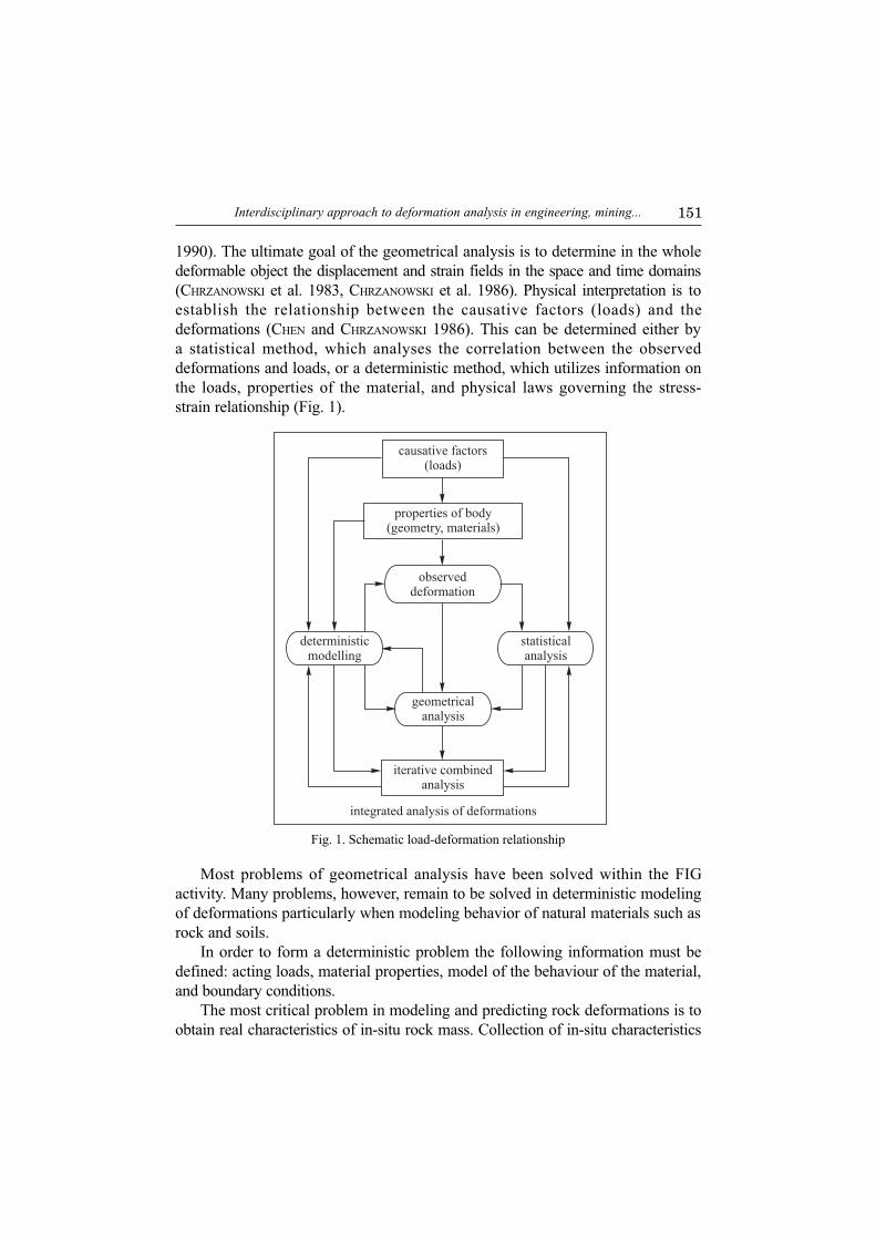
1990). The ultimate goal of the geometrical analysis is to determine in the wholedeformable object the displacement and strain fields in the space and time domains(CHRZANOWSKI et al. 1983, CHRZANOWSKI et al. 1986). Physical interpretation is toestablish the relationship between the causative factors (loads) and thedeformations (CHEN and CHRZANOWSKI 1986). This can be determined either bya statistical method, which analyses the correlation between the observeddeformations and loads, or a deterministic method, which utilizes information onthe loads, properties of the material, and physical laws governing the stress-strain relationship (Fig. 1).
Fig. 1. Schematic load-deformation relationship
causative factors(loads)
integrated analysis of deformations
properties of body(geometry, materials)
observeddeformation
deterministicmodelling
statisticalanalysis
geometricalanalysis
iterative combinedanalysis
Most problems of geometrical analysis have been solved within the FIGactivity. Many problems, however, remain to be solved in deterministic modelingof deformations particularly when modeling behavior of natural materials such asrock and soils.
In order to form a deterministic problem the following information must bedefined: acting loads, material properties, model of the behaviour of the material,and boundary conditions.
The most critical problem in modeling and predicting rock deformations is toobtain real characteristics of in-situ rock mass. Collection of in-situ characteristics

152 Anna Szostak-Chrzanowski
of rock is very difficult and very costly and the data is often incomplete. Inlaboratory testing, the selected samples may differ from one location to another,they may be disturbed during the collection, or the laboratory loading conditionsmay differ from natural conditions. This is especially valid in case of soil testing.The physical values obtained from laboratory testing require scaling in order torepresent a rock mass. The process involves a degree of uncertainty. Generally,four types of scale are distinguished: (1) sample as an intact rock; (2) rock inthe vicinity of opening with some joints; (3) rock with many joints; and (4) rockas a rock mass. The problem of scale-dependent properties is a main problem inmodeling rock behavior (GLASER and DOOLIN 2000).
One of the important problems in rock mechanics is to model the Youngmodulus and the strength of the rock material, which vary through the in-siturock mass. Generally, Youngs modulus of in-situ rock masses is smaller thanthe values obtained in a laboratory (BIENIAWSKI 1984, SAKURAI 1997). Thematerial strength decreases with the size of the model where large fractures arepredominant. In case of soil or rockfilled material (e.g. embankment dams), thevalues of geotechnical parameters change during and after construction. Duringfilling up a reservoir the earth dams undergo a process of wetting of thematerial in selected zones. The material properties may considerably differbetween dry and wet conditions (TOUILEB et al. 2000).
Another important problem in numerical modeling is the selection of thematerial behavior model. The model of linear elasticity is still most widely usedin modeling behavior of rocks, especially hard rocks (JING 2003). More sophisticatedconstitutive models used in rock mechanics are, for example, non-tensionalmodel (ZIENKIEWICZ et al. 1968), anisotropic elasticity, plasticity, elasto-plasticity,and visco-elasticity. Plasticity and elasto-plasticity models used in rock mechanicsare typically based on Mohr-Coulomb and Hoek-Brown failure criteria (HOEK
and BROWN 1982). Visco-elastic models are used in salt rock or other weakrocks and may be based on a reological model (OWEN and HINTON 1986). Thesalt rock was also modeled as non-Newtonian liquid (DUSSEAULT et al. 1987).Behaviour of the soil material may be analysed using a hyperbolic non-linearmodel describing the behaviour of soil before failure (KONDNER 1963, KONDNER
and ZELASKO 1963, and DUNCAN and CHANG 1970). Use of more sophisticatedconstitutive models in rock mechanics may be limited by a difficulty in obtainingnecessary parameters.
A combination of a deterministic model with observed deformations may beused either in forward or back analysis. In forward analysis, the physical parametersare used as input data, while expected displacements, strains, and stresses arecalculated. The displacements are calculated using the equilibrium equation:
Kd = r fb fso feo (1)

153Interdisciplinary approach to deformation analysis in engineering, mining...
where d = (u1 v1 w1 u2 v2 ... un vn wn)T is the vector of displacements, K isthe global stiffness matrix of the material, fb is the loading vector of bodyforces, fso is the loading vector from initial stresses, feo is the loading vectorfrom initial strains, and r is the vector of external forces.
In back analysis, measured displacements are taken as input data and theyare used to calculate unknown parameters such as material properties, loads,and initial stresses. Recent developments in automatic geodetic data collectionand remote sensing monitoring techniques allow for collecting of large data setsof high precision for the back analysis of deformations.
Back analysis can be divided into: 1) inverse analysis (with assumptions thatthe investigated material is uniform and that the initial stress field is uniform orlinear); 2) optimization method. The concept of back analysis was presented bySAKURAI and TAKEUCHI (1983); GIODA and SAKURAI (1987). In most cases of backanalysis, the modeled material is considered as elastic (JING 2003). For instance,back-analysis method used in modeling of rock behavior around tunnels waspresented by ZIHIFA at al. (2000). The only example of back analysis for largescale problem modeling was given by CHI et al. (2001). However, the analysiswas based on an empirical formula, which was developed for ground movementdue to tunneling. Optimization methods may be used in cases of modelingcomplex initial stresses and multiple strata types (DENG and LEE 2001). GENS etal. (1996) and LEDESMA et al. (1996) used probabilistic formulation to estimateparameters from field instrumentation.
2.2. Finite Element Method
The basic concept of the finite element method (displacement approach) isthat the continuum of the deformable body is replaced by an assemblage ofindividual small elements of finite dimensions, which are connected together onlyat the nodal points of the elements (ZIENKIEWICZ and TAYLOR 1989). Theelements may be of any shape, but usually eight nodal brick elements, threenodal elements and four nodal elements are chosen for a three- and two-dimensional analyses, respectively. For each element, one can establish therelationship between the nodal loads and displacement or strain field variables.
The global matrices and vectors in the equilibrium equation (1) are calculatedthrough a superimposition of local (at each element or at each node of the FEMmesh) matrices Ke and vectors fe
b, feso, and fe
eo. The local stiffness matrix andlocal loading vectors in individual elements are calculated from:
Te c cdxdy dz
Ω∫K B DB (2)

154 Anna Szostak-Chrzanowski
Te c cdxdy dz
Ω∫K B DB (3)
where Be is the matrix relating strains in the element to its nodal displacements,Ne is the shape function, D is the constitutive matrix of the material, which incase of the linear elastic analysis, contains the elasticity parameters such as Youngmodulus E and Poisson Ratio n, and b = (bx by bz)
T is the vector of body force.The transformation of the global stiffness matrix may be expressed as:
1
neTe e e
e
K T K T=
= ∑ (4)
The functions in equations (2) and (3) are given in x, y, z global coordinates.By introducing local coordinates x, h, and z in an element, one can write:
( ) ( ) [ ]1 1 1
1 1 1
, , , , detF x y z dxdy dz G J d d dξ η ζ ξ η ζ− − −
=∫∫∫ ∫ ∫ ∫ (5)
where det[J] is the determinant of Jacobian matrix.
Using the Gaussian quadrature rule (ZIENKIEWICZ and TYLOR 1989), one can write:
( ) [ ] [ ] ( )1 1 1
1 1 11 1 1
, , det det , ,n n n
i j m i j mm j i
G J d d d W W W J Gξ η ζ ξ η ζ ξ η ζ= = =− − −
= ∑ ∑ ∑∫ ∫ ∫ (6)
where W are weights.
In order to evaluate matrix G, a transformation of the coordinates isnecessary. The coordinate transformation is established using standard shapefunctions N given in terms of local coordinates.
Since the stiffness matrix K is singular, boundary conditions must be appliedin order to solve equation (1) for the displacements. Assume that thedisplacement boundary conditions are given by
HTd = d (7)
where d is a vector of known displacements and H is a location matrix. Then,the solution of equation (1) is given by

155Interdisciplinary approach to deformation analysis in engineering, mining...
( ) ( )1TK sHH f sHdδ
−= + + (8)
where s is a scale factor which should be chosen to be sufficiently largeaccording to the computer capability.
Most of the numerical codes for rock mechanics are suitable for small-scalestudies (JING 2003). Commercial codes for large-scale studies in structuralengineering may lack some important capabilities for the determination of thequality of calculated quantities. Among many commercial finite elementprograms one can list COMSOL Multiphysics and GEO-SLOPE (KRAHN
2004), which are used by the author in solving some forward problems.The author developed FEMMA software (Finite Element Method for
Multiple Applications) to investigate large scale problems in rock mechanics(SZOSTAK-CHRZANOWSKI et al. 1991b, 1994).
2.3. Accuracy of Deterministic Modeling
In order to perform a meaningful combined analysis of deformations, theaccuracy of both geometrical and deterministic models must be known. Thisrequirement applies, for instance, when different hypotheses regarding thedeformation mechanism are put forward, and one would like to identify the mostappropriate hypothesis on the basis of a comparison of observed deformationswith deterministic values (CHRZANOWSKI et al. 1994). While the accuracy ofgeometrical models (CHRZANOWSKI et al. 1986) may be easily determined fromthe knowledge of the errors of the observed deformations, the accuracydetermination of the finite element model poses some problems that have not yetbeen fully solved.
In both forward and back analyses, input data is affected by errors ofmeasurements and estimation. The accuracy of FEM analyses depends mainly on:(1) discretization error, (2) computer round-off errors, (3) matrix ill-conditioning,and (4) errors in the physical parameters of the material and input boundaryconditions (observed loads and/or deformation). These effects never allow foran exact solution to be obtained. Therefore, users of the finite element methodmust always be aware of the accuracy limitations and should always performa quantitative analysis of the errors of the FEM results before using them forany further analysis and/or interpretation.
The influence of the first three factors has been extensively investigated anddiscussed in the literature by many authors (e.g., ZIENKIEWICZ and TAYLOR 1989).The influence of errors in the physical parameters of the material and errors in

156 Anna Szostak-Chrzanowski
the boundary conditions, though generally recognized, particularly in rock and soilmechanics, as the main sources of errors in FEM analyses, has lacked a rigoroustreatment. These errors may be classified into two groups, (a) systematic biasesfrom the true values and (b) random uncertainties.
The influence of a systematic bias, for example a difference between the in-situ and laboratory values of Young modulus, E, can be introduced into the erroranalysis in a trial and error mode by performing the FEM analysis separatelyfor each value of Young modulus and checking whether the difference in theoutput results is significant. Propagation of random errors, however, is muchmore complex and requires a rigorous propagation of variances and covariancesof the parameters, which are treated as random variables. This approach isparticularly important in any rock mechanics problems where mechanicalproperties of the same type of rock may be significantly changing from onelocation to another due to inhomogenities and discontinuities in the rock material.In this case, even if in-situ determination of the properties is performed, it canbe done only at a few discrete points while in other places the values may differrandomly within a certain, statistically determined, confidence (±) interval. Theconcept of variances-covariances propagation in FEM was introduced by SZOSTAK--CHRZANOWSKI et al. (1994). The effect of input data errors for the failure envelopewas investigated by ZAMBRANO-MENDOSA et al. (2003).
3. Developments in deformation analysis
3.1. Areas of Authors Research and Development
The Authors research has concentrated on:1 optimal use of deterministic modeling in predicting structural and ground
deformations in engineering, mining, and geoscience projects;2 optimal combination (integration) of deterministic and geometrical models for
the purpose of identifying the mechanism of deformation and explaining cau-ses of the observed deformations;
3 optimal combination of deterministic models with observed deformations forthe verification of material properties of the deformable body at the con-struction and post-construction (operation) stages;
4 propagation of variances-covariances in FEM;5 modeling of gravity changes.
The presented research has concentrated on the analysis of large-scaleproblems using finite element analysis. The author developed a concept ofequivalent (averaged) medium which may be divided into a few interactingblocks. The concept is used in forward and back analyses for studying the

157Interdisciplinary approach to deformation analysis in engineering, mining...
behavior of the rock mass. The material model for the equivalent medium hasbeen developed on the basis of the determination of the deformation modulus asa function of time.
Since the properties of the in-situ rock may significantly differ from theresults of the laboratory tests, methods for calibrating mechanical properties ofrock or soil mass have been developed using a calibrating function, which isbased on the distribution of compressive and tensional stresses. In addition, theauthor developed a methodology for the identification of material parameters ofboth brittle and salt (viscous) rock with application to mining problems and forsoil structures with application to embankment dams. Modeling of brittle rockdeformation is based on a non-tensional model of the behavior, while modelingof salt rock deformation is based on the assumption that the salt rock behavesas non-Newtonian liquid.
The author, in her research has concentrated on the development ofa methodology to model in-situ mechanical parameters for rock and for saturatedsoils. The scale ratio of laboratory Young modulus to in-situ Young modulus forintact rock is based on stress distribution in the rock mass. The investigated rockmass is divided into selected blocks: rock in the vicinity of the opening with somejoints; rock with many joints; or rock as a total rock mass (SZOSTAK-CHRZANOWSKI
and CHRZANOWSKI 1991a). On the basis of stress distribution, the author alsoderived the scale ratio of a laboratory value of tensional strength to the in-situvalues (SZOSTAK-CHRZANOWSKI and CHRZANOWSKI 1991a). The assumptionsregarding the behavior model of rock mass is used as a basis for the identificationof boundaries of blocks within the rock mass with assigned to each block scaledparameters (CHRZANOWSKI et al. 2000).
3.2. Use of integrated analysis and separability concept in identificationof deformation mechanism
In some cases of unexpected deformation of man-made or natural structuresthe causative factors may not be known. For example, the mechanism andcausative factors of tectonic movements are usually not well known, and they aresubjected to various hypotheses. The main purpose of the concept of integratedanalysis developed by the author is to identify, on the basis of a comparison (ora simultaneous analysis) of geometrical and deterministic models, which of thepostulated mechanisms can be optimally explained by the analysis. Depending onthe design and accuracy of the monitoring surveys, the separation (discrimination)among various postulated mechanisms may not be possible (CHEN and CHRZANOWSKI
1994). For instance, if only geodetic levelling is used as the main tool to describethe surface effects of tectonic movements then one may be not able to deduce

158 Anna Szostak-Chrzanowski
whether the observed vertical movements are caused by a thermal expansion ofthe earths crust or by a subducting tectonic plate or by both. In order to distinguishbetween these mechanisms, measurements of relative horizontal movements orgravity changes could help in the identification of the best model (SZOSTAK--CHRZANOWSKI et al. 1993b).
In order to identify the best model, the author has combined the integratedanalysis with the concept of separability (CHEN et al. 1994). The concept andmethodology require a priori knowledge of the expected deformation pattern. Thiscan be obtained from deterministic modeling of deformations using, for example,the FEM analysis with assumed material parameters and boundary conditions. Thecomputed displacements or their derived quantities, e.g., strains, are thencompared with the measured ones. The correlation between them is calculated,and the most appropriate deformation mechanism is identified. On the other hand,based on deterministic patterns of expected deformations for various hypothesesof deformation mechanisms, a monitoring scheme can be optimally designed usingthe criterion of separability (CHEN et al. 1994, CHRZANOWSKI et al. 1994).
When m postulated models are considered then the separability criteria are:
( )20 0
min 2iji
Mb
σ δλ ≥ for all i, j(i ¹ j) (9)
with
( ) 1T T T Tij i i i j j j j i
−= −d d d dM B P B B P B B P B B P B (10)
where Pd is the weight matrix (which is a function of the configuration andsurvey errors of the monitoring scheme) of the displacement vector, s0
2 is thevariance factor, d0 is the boundary value of the noncentrality parameter,bi (i = 1, 2, ..., m) is the smallest deformation to be correctly detected, and Bi isthe deformation matrix, which is formulated from the displacements calculatedusing FEM. If the accuracy of monitoring surveys is inadequate to achieve aseparation between two or more models than the surveys must be redesigned tochange Pd (i.e. change the type, configuration, and accuracy of the surveys) ina such way that a better separation between different deformation models couldbe achieved.
The author adapted and implemented the concepts of integrated analysis andseparability to studies of earth crustal movements (SZOSTAK-CHRZANOWSKI et al.1993b, CHRZANOWSKI et al. 1994) including modeling of tectonic movements inWestern Canada (SZOSTAK-CHRZANOWSKI et al. 1996).

159Interdisciplinary approach to deformation analysis in engineering, mining...
3.3. Software FEMMA
In order to implement developments in the back analysis, the separabilityanalysis, and the error analysis the author developed FEMMA software. Thesoftware has been developed in two main versions, FEMMA 2.0 and FEMMA3.0, for two- and three-dimensional: forward and back deformation analysis;thermal analysis: steady state heat-transfer; and error propagation analysis.Modeling of gravity changes is accomplished in an additional version ofsoftware. All versions of FEMMA are supported by the automatic meshgeneration software MESHGEN 2.0 and 3.0.
Special characteristics of FEMMA are:1 optional use of either two-nodal (bars), or three-nodal (triangular), or four-
nodal elements in the two-dimensional analyses and use of eight nodal(bricks) elements in three-dimensional problems;
2 modelling of discontinuities using either the split node technique (MELOSH andRAEFSKY 1981) or anisotropic elements;
3 use of no-tension criteria and Hoek-Brown criteria (HOEK and BROWN 1982)in rock deformation studies.The modular structure of the software allows for an easy introduction of
additional changes and adaptations for various applications.
3.4. Propagations of Errors in FEM
3.4.1. Propagation of random errors in forward analysisResults of any measurements (treated as random variables) or quantities
derived from random variables are meaningless unless they are accompanied byinformation on their accuracy. Terms such as variance, covariance, standarddeviation, confidence level, and probability, are commonly used in accuracyanalysis (e.g., MIKHAIL 1976).
If a set of n unknowns ui (vector u) is computed from a set of k knownvariables zi (vector z) that have known variances and covariances (matrix Cz),then according to the general formula, known as the propagation of variance--covariance matrices, one can calculate the variance-covariance matrix Cu ofthe unknowns from
Cu = A Cz AT (11)
where A is the design matrix containing partial derivatives of the functionsui = ui(z1, z2, , zk), where i = 1, 2,, n at the approximate points of variables.

160 Anna Szostak-Chrzanowski
In forward analysis the Young modulus E, Poisson Ratio n, initial stress so,initial strain eo, and body forces b are typical input data. If one treats thevariables E, n, so ,eo, r, and body forces b in each element as random variableswith a known variance covariance matrix Cz, then, using the general rule(equ.11) of the error propagation, one can calculate the variance-covariancematrix Cd of the nodal displacements. Where
, ... ...y
AE b
δ δ δν
∂ ∂ ∂= ∂ ∂ ∂ (12)
with
( ) 1
1
neT T T
e e e ee
DK sHH T T B B t dxdy
E E
δ δ−
=
∂ ∂= − + −∂ ∂∑ ∫∫ (13)
( ) 1
1
neT T T
e e e ee
DK sHH T T B B t dxd
δ δν ν
−
=
∂ ∂= − + −∂ ∂∑ ∫∫ (14)
( ) 1
1
0
1
neT T T
e ex e
K sHH T N t dxdyb
δ −
=
∂ = + ∂ ∑ ∫∫ (15)
In case of a plane strain, two-dimensional analysis
1 01
1 0(1 )(1 2 )
1 20 0
2
D
E
ν νν ν
ν νν
− ∂ = − ∂ + − −
(16)
2
1 0 1 1 0(1 4 )
1 0 1 1 0(1 )(1 2 )(1 )(1 2 ) 1 2 0 0 1
0 02
D E Eν ν
ν ν νν ν νν ν ν
− − ∂ + = − + − ∂ + −+ − −
(17)
More details on the developed methodology are given in SZOSTAK-CHRZANOWSKI
et al. (1993a).

161Interdisciplinary approach to deformation analysis in engineering, mining...
3.4.2. Propagation of random errors in back analysisThe author developed a methodology for modeling large-scale problems
using back analysis. The principal equation of back analysis is based on equation (1)of equilibrium. Let d1* be the vector of measured displacements and d2 is avector of the remaining (unknown) nodal displacements. Equation (1) isrewritten as
*11 12 11
21 22 22
K K fdK K fd
=
(18)
Eliminating d2 results in
( )1 * 111 12 22 21 1 1 12 22
− −− = −K K K K d f K K (19)
which is rewritten as
* * *11 1 1=K d f (20)
Equation (20) represents the basic equation governing the back analysis problem.If there are u unknown parameters to be estimated in the left-hand side of
the equation or in matrix *11K , and m observed displacements, where m > u,
then the unknown parameters can be solved by using the least-squares technique.Let u unknowns in matrix *
11K be denoted by p, and let p0 be theirapproximate values, then the least-squares solution for p is performed byminimizing the quadratic form
* 1 *1 1( ) ( )− − − d d p C d d p (21)
where C is the variance covariance matrix for the observed displacements, and
1* *11 1( ) ( ) min
− = = d p K p f (22)
Since *11K is a non-linear function of the unknown parameters p, linearization
with respect to p(0) is made. The corrections to the approximate values p(0) arethen estimated from
11 1 * 01 ( )T T−− − ∆ = − p A C A A C d d p (23)

162 Anna Szostak-Chrzanowski
where A is the partial derivatives of d(p) with respect to p and is evaluated atthe values of p0. Since this is a nonlinear problem, an iteration process is needed.
Finally, the variance covariance matrix of the estimated parameters iscalculated from:
11T −− = pC A C A (24)
The same back analysis procedure holds for unknown parameters in theright-hand side of equation (20). Examples of the error analysis in back analysisare given in SZOSTAK-CHRZANOWSKI et al. (1994).
3.5. Modeling of ground subsidence in mining areasas a large-scale problem
3.5.1. Earlier methods of mining subsidence modelingModeling of ground subsidence in mining areas may be performed using
either geometrical (empirical) theories or deterministic analysis. Geometricaltheories for predicting the ground subsidence have been developed in centralEurope and the United Kingdom. The first theories were developed by KEINHORST
(1925), followed by BALS (1932). Within that group of theories, KNOTHES (1957)influence function theory, developed in Poland, has gained the most popularityand has been used (sometimes with modifications) till now in many countries,including adaptations in the U.S.A. (e.g., LUO and PENG 1993), and in P.R. China.
In geometrical models, some parameters (coefficients) of the functions mustbe determined (calibrated) empirically through a comparison with the observedsubsidence. Since other parameters, such as mechanical properties of the rockand tectonic stresses, are not taken into account, the prediction theories areapplicable only to the areas where the mining, geological, and tectonic conditionsare the same or very similar to the area where the empirical data for the theoryhad been collected. Since the conditions in different areas are never the same,any attempt to adapt, for instance, the European geometrical methods for groundsubsidence prediction on the North American continent requires the calibrationof the model parameters through many years of comparisons with the observeddeformations in the new area. Usually, this approach is unrealistic because veryfew mines in North America have a well organized and systematic program ofmonitoring surveys. It also should be stressed that the geometrical theories aregenerally not reliable in cases of complicated geometry of mined deposits, in thepresence of faulting, and in areas of previous extensive mining operations.
Most of the 150 or so currently active underground mines in Canada are inhard rocks and are located in sparsely populated areas. Therefore, except for

163Interdisciplinary approach to deformation analysis in engineering, mining...
a few coal and potash mines, the effects of mining on the surface infrastructurehave never been a major concern. The leading geomechanical problem inconditions of Canadian mining has been to understand damage and failurearound mining openings (small scale problems) excavated in brittle rock massunder high in situ stresses (CASTRO 1997). Most of the research and analyses ofthe rock strata behavior around mine openings in mining areas were based onsmall-scale problems using numerical modeling (UDD and YU 1993, CORKUM etal. 1991, RIZKALLA and MITRI 1991, SURIYACHAT and MITRI 1991).
Over the past 30 years, most Canadian mines have started recognizing theimportance of improving their monitoring techniques and methods of modelingand predicting of rock strata deformation not only for safety and environmentalprotection purposes but first of all for a better understanding of the mechanismof rock strata deformation leading to the development of more economical andsafer mining methods.
The first attempts to use numerical FEM in ground subsidence were madein 1975 (VONGPAISAL and COATES 1975) and applied to the Falconbridge Sudburymining operation. FEM code was developed to model stress distribution inpotash mines (FOSSUM 1985). At the same time, the author initiated research onthe development of a deterministic model of deformations and stress distributionin rock mass also using FEM (Szostak-CHRZANOWSKI 1988). In 1989, the authorpresented a method (known as S-C method) to model and predict groundsubsidence in brittle rock (SZOSTAK-CHRZANOWSKI 1989)
3.5.2. Development of methodology for subsidence modeling basedon large scale problem modeling
The author developed a methodology (known as S-C method), based onlarge-scale problem modeling, for brittle rock deformation. The method is basedon the assumption that the brittle rock behaves as non-tensional material(SZOSTAK-CHRZANOWSKI and CHRZANOWSKI 1991b). The S-C method wassuccessfully implemented in modeling and predicting of ground subsidence inseveral coal, copper, lead and zinc mines (SZOSTAK-CHRZANOWSKI 1988, SZOSTAK--CHRZANOWSKI and CHRZANOWSKI 1991b) including modelling of seafloorsubsidence over offshore coal mining in Nova Scotia (CHRZANOWSKI et al. 1998);and modelling of ground subsidence and identification of a fault over a steeplyinclined coal seam near Sparwood, B.C. (SZOSTAK-CHRZANOWSKI and CHRZANOWSKI
1991b).The S-C method was expanded to model deformations in salt rocks. The
application to the prediction of ground subsidence in potash and salt mining attwo mines in New Brunswick is described in CHRZANOWSKI and SZOSTAK--CHRZANOWSKI (1997) and CHRZANOWSKI and SZOSTAK-CHRZANOWSKI (2004). Themethod is supported by software FEMMA.

164 Anna Szostak-Chrzanowski
In the the authors deterministic analysis of subsidence of salt and potash rockmass, the rock material is considered as a non-Newtonian liquid with high and notconstant viscosity (DUSSEAULT et al. 1987). The initial stress in the intact salt rockwas assumed to be isotropic lithostatic. Development of shearing stresses due tomining activity causes the flow of the salt mass into the excavated areas in orderto achieve a new equilibrium state of stresses. Shearing stresses are developeddue to de-stressing of the salt rock over a mining opening and due to an increasein compressive stresses at the sides of the mining cavity. The flow-in zone isidentified within the zone delineated by maximum shearing stresses. In modelingthe final maximum subsidence at the top of the salt formation, the value of E inthe flow zone is scaled to give the same volume of the subsidence basin (underthe cap rock) as is the volume of mining openings. Once the equivalentsubsidence trough at the top of the salt is determined, the response of the brittlerock is modeled (SZOSTAK-CHRZANOWSKI and CHRZANOWSKI 1991a).
3.5.3. Modeling of subsidence due to withdrawal of liquidsA change in underground fluid (water or oil) conditions may cause surface
subsidence. The change of water condition may be due to pumping to thesurface or due to an inflow into the mining openings. Vertical flow of groundwater, horizontal flow, and inelastic compaction of the material of aquifersystems are important parameters.
The aquifer system from which the water flows may be composed of layersof coarse or fine-grained material (sediments, sand, porous sandstone). Thecompaction of the material may be elastic or inelastic and is characterized by anelastic or inelastic storage coefficient of the compaction. The depth of the aquiferalso has an influence on subsidence. The total stress in the aquifer is caused bythe weight of the overlying rock and water. The effective stress is the resultingstress of total stress and acting upward stress caused by water pressure. Inconfined aquifers, there can be large changes in pressure with little change ofthickness of the saturated water column. Therefore, the total stress may remainpractically constant, but the change in pressure will result in change in effectivestress. The aquifer may consolidate or compact due to increased stress. Forexample, a confined aquifer with an initial thickness of 45 m consolidates 0.20 mwhen the head is lowered by 25 m (FETTER 1942). The deformation may becalculated using the theory of consolidation of one dimension. The subsidencemodel derived by BRAVO et al. (1991) uses the principle of relationship of elasticcompaction of soil and ground-water piezometric head.
The author incorporated the principles of compaction analysis to integrated analysisof subsidence due to water inflow into the aforementioned PCA mine (SZOSTAK--CHRZANOWSKI et al. 2005). Currently, the author is developing a methodology formodelling ground subsidence in oil fields (SZOSTAK-CHRZANOWSKI et al. 2006b).

165Interdisciplinary approach to deformation analysis in engineering, mining...
4. Numerical modeling of gravity changes
Relocation of rock masses and/or change of density, and change of height dueto human (e.g., mining) activities or tectonic activity may produce significant localchanges to the gravity field in the vicinity of activity. The gravity changes result inlocal tilts of the level surface (equipotential surface of gravity) and, consequently,changes of the direction of the plumblines to which the majority of geodetic andsome geotechnical measurements are referenced. Thus, if any geodeticmeasurements of high precision are required during the mining operation, forexample, for the purpose of monitoring the stability of surface structures, they shouldbe corrected for changes of gravity and deflection of the vertical as a function oftime. Otherwise, differences in the repeated observations (angles, distances,gyroazimuths, height differences, tilts, etc.) caused by the gravity changes could bemisinterpreted as deformations of the observed object. In addition, by comparingthe expected (modeled) gravity changes with the values observed with precisiongravimeters, one may gain information on the behaviour of the rock massesdisturbed by mining activity or affected by activity of tectonic origin. Variousaspects of the mining microgravimetry are discussed in FAJKLEWICZ (1980).
The calculation of gravity changes involves solving complex integrals(summation of influences of point masses). The theory of gravity and variousnumerical methods used in the gravity calculations, are given in textbooks ongeodesy, for example in VANICEK and KRAKIWSKY (1986), TORGE (1991),HEISKANEN and MORITZ (1967).
The author has developed a method for numerical modeling (using FEM) ofgravity changes caused by the simultaneous effects of mass relocation and rockdeformations. The method is based on dividing the investigated object into thefinite number of elements and on summation of gravity due to change of densityat the point caused by each of the finite elements.
Derivatives of the potential of the gravitation with respect to x, y, z, ina Cartesian coordinate system give the components of the gravity. For example,x component is given as:
( )dv
R
xxGg
Vx ∫−′
−=31r (25)
where r1 is the initial density, and R is the radius calculated from
( ) ( ) ( )1/ 22 2 2R x x y y z z ′ ′ ′= − + − + − (26)
and x, y, z are the coordinates of mass m1 and x¢, y¢, z¢ are the coordinates ofmass m2.

166 Anna Szostak-Chrzanowski
The gravity may change due to the changes of mass or changes of densitywith constant mass, due to the deformation caused by acting loads. Thedifference between the gravity values at the two epochs may be a result of themass change due to, e.g., open pit mining activities or a change in the densitycaused by the change in the strain field.
If the gravity were calculated at two epochs, the gravity change would be adifference between the gravity values at time 1 and time 2, i.e.:
1 2g g g∆ = − (27)
The new density based on an assumption of constant mass is expressed by
12 1
2
V
Vρ ρ= (28)
where r1 and r2 are the densities and V1 and V2 are volumes before and afterthe deformation, respectively.
Using equation (25) and equation (28) the gravity change, dgd, due to thechange of density is calculated from
( )dv
R
zz
V
VGg
V∫−′
−=2
32
112 r (29)
The gravity change is calculated as a sum of the effects calculated for eachelement of the finite element model using Gaussian quadrature rule. The volumeof each element is calculated from changes of the coordinates of the nodalpoints obtained from the stress-strain finite element analysis. The same finiteelement mesh is used to calculate gravity change components.
The method has been used in modeling regional deformations and gravitychanges of tectonic origin (SZOSTAK-CHRZANOWSKI et al. 1996) and in modelingexpected gravity changes in a large open pit mine, Belchatow, in Poland(SZOSTAK-CHRZANOWSKI et al. 1995).
5. Verification of material parameters of earth dams integrated approach
During construction, earthen dams undergo a settlement that consists of twocomponents: crossarm settlement and pre-crossarm settlement. The crossarmsettlement is defined as a settlement at a given location and elevation due to the

167Interdisciplinary approach to deformation analysis in engineering, mining...
weight of overlying material. It reaches its maximum value approximately at themid-elevation of the dam. The pre-crossarm settlement is the settlement ata given location and elevation due to weight of the underlying material.
At the stage of filling the reservoir, two main effects must be considered:pressure of water and effect of wetting. During the process of wetting, thevalues of geotechnical material parameters and the derived values of Youngmodulus decrease. Young modulus of the material in the submerged sections ofthe structure becomes smaller and buoyancy force is developed producing damdeformation. The wet parameters are smaller than dry parameters for the samesoil. The rock mass on which the embankment dam is located may be assumedto behave as a linear-elastic material under the load of the weight of the damand the weight of water in the reservoir.
The behaviour of the earth material may be determined using a hyperbolicnon-linear model describing the behaviour of soil before failure developed byKONDNER (1963) and KONDNER and ZELASKO (1963). In the hyperbolic model, thenon-linear stress- strain curve is a hyperbola in s1s3 versus axial strain plane.The relationship takes the form modified by DUNCAN and CHANG (1970):
(3 ) (3 ) 03
(3 ) (3 ) 09
0 0
x x
y y
xy xy
B E B EB
B E B EB E
E
σ εσ ε
τ γ
∆ ∆+ − ∆ = − + ∆ − ∆ ∆
(30)
where Ds and Dt are stress increments and De and Dg are strain increments,E is Young modulus, and B is bulk modulus.
The relation of initial tangent modulus Ei and confining stress 3σ ′ is given byJANBU (1963):
3n
i aPa
E KPσ
=′
(31)
Similarly the relation between bulk modulus B and confining stress 3σ ′ canbe determined (DUNCAN et al. 1980):
3m
b aa
B K PP
σ ′ =
(32)
where Pa is atmospheric pressure, K is loading modulus number, and n isexponent for loading behaviour. Kb is bulk modulus number and m is bulkmodulus exponent.

168 Anna Szostak-Chrzanowski
The author developed a methodology for modelling and verification ofgeotechnical parameters of large earth dams built using different technologies. Inthe process of the calculation of displacements the author determined the changeof geotechnical parameters and Young modulus of the zones in a dam betweendry and wet conditions. Results of geodetic deformation surveys have been usedin verifying design geotechnical parameters of various earth dams (SZOSTAK--CHRZANOWSKI et al. 2002, 2006a, SZOSTAK-CHRZANOWSKI and MASSIERA 2004)
The agreement of deformations obtained from FEM solution and monitoringmay confirm that the geotechnical parameters and the values of Young modulus,as used in the FEM analysis are correct. This is an important conclusion fora possible use of the verified parameters in future analyses of possible effectsof additional loads arising, for example, from tectonic movements. A goodunderstanding of the deformations occurring in embankment dams allows forminimizing the effects such as transverse cracking, longitudinal fissuring, archingeffect and stress concentration, hydraulic fracturing, development of plasticzones, and damages in the instrumentation.
6. Conclusions
The authors new developments in integrated analysis of deformationssignificantly increased the role of geodetic monitoring surveys in physicalanalysis of deformations. They also have enhanced the process of understandingthe mechanism of deformations in civil engineering, mining, and naturaldeformations such as tectonic movements.
The development of a method for modeling and predicting rock deformationsdue to mining activity, hydrological changes, or oil withdrawal is a speciallyimportant contribution. The S-C method developed by the author for modeling ofdeformations of rock mass is universal and gives good results.
References
BALS R. 1932. Beitrag zur Frage der der Vorausberechnung bergbaulicher Senkungen, mitt.Markscheidew, 42(43): 98-111.
BIENIAWSKI Z.T. 1984. Rock Mechanics Design and Tunneling. Balkema.BRAVO R., ROGERS J.R., CLEVELAND T.G. 1991. Analysis of Ground Water Level Fluctuations and
Borehole Extensometer Data from the Bayton Area. Houston, Tx, Land Subsidence, ed. A.J.Johnson, Proceedings of the Fourth International Symposium on Land Subsidence, Houston,12-17 May, pp. 655-666.
CASTRO L. 1997. How to Enhance Geomechanical Design of Deep Openings. Proceedings CIM,Vancouver, April, 27-30, pp.105.
CHEN Y.Q., CHRZANOWSKI A. l986. An overview of the physical interpretation of deformation
169Interdisciplinary approach to deformation analysis in engineering, mining...
measurements. Deformation Measurements Workshop, MIT, Boston, Oct. 31-Nov. l, Proce-edings (MIT), pp. 207-220.
CHEN Y.Q. CHRZANOWSKI A. 1994. An approach to separability of deformation models. Zeitschr. f.Vermessungswesen, 119(2): 96-103.
CHEN Y.Q., TANG C., ZHOU S. 1994. Design of monitoring networks using the criterion of separa-bility. Presented at FIG XX Congress, Melbourne, Australia, paper 602.1.
CHI, SHUE-YEONG, JIN-CHING CHERN, CHIN-CHENG LIN. 2001. Optimized back analysis for tunnelinginduced ground movement using equivalent ground loss model. Tunneling and UndergroundSpace Technology, 16: 159-165.
CHRZANOWSKI A., CHEN Y.Q., SZOSTAK-CHRZANOWSKI A. 1983. Use of the Finite Element Method inthe Design and Analysis of Deformation Measurements. Proceedings, FIG-XVII Congress,Sofia, Bulgaria, June 19-28, Paper, 611.1.
CHRZANOWSKI A., CHEN Y.Q., SECORD J. 1986. Geometrical analysis of deformation surveys. Deform.Measurements Workshop, MIT, Boston, Oct. 31-Nov. l, Proceedings (MIT), pp. 170-206.
CHRZANOWSKI A., CHEN Y.Q., SZOSTAK-CHRZANOWSKI A., SECORD J.M. 1990. Combination of Geo-metrical Analysis with Physical Interpretation for the Enhancement of Deformation Modeling.Proceedings of the XIX-th International Congress FIG, Helsinki, Finland, 10-19 June, 6: 326-341.
CHRZANOWSKI, A., CHEN Y.Q., SZOSTAK-CHRZANOWSKI A., OGUNDARE J. 1994. Separability of Com-bined Deterministic and Geometrical Models of Deformation. Proceedings of the XX-th Inter-national Congress FIG, Melbourne, Australia, 5-12, March, 652.1.
CHRZANOWSKI A., SZOSTAK-CHRZANOWSKI A. 1997. Modelling and Prediction of Ground Subsidencein Potash Mines. Proceedings of the 10th International Congress of the International Societyfor Mine Surveyng (published by Promaco Conventions Pty Ltd.), Fremantle,W. Australia,2-6 Nov., pp. 507-512.
CHRZANOWSKI A., SZOSTAK-CHRZANOWSKI A., FORRESTER D.J. 1998. 100 Years of ground SubsidenceStudies. 100th General Meeting of CIM, Montreal, May 3-7, Proceedings (Canadian Instituteof Mining) CD-ROM, CIM Montreal 98.
CHRZANOWSKI A., SZOSTAK-CHRZANOWSKI A., BASTIN G., LUTES J. 2000. MONITORING AND MODELING
OF GROUND SUBSIDENCE IN MINING AREAS- CASE STUDIES. Geomatica, pp. 405-413.CHRZANOWSKI A., SZOSTAK-CHRZANOWSKI A. 2004. Physical Interpretation of Ground Subsidence
Surveys A Case Study. Journal of Geospatial Engineering, Hong Kong Institute of Engine-ering Surveyors, pp. 21-29.
CORKUM B.T., CURRAN J.H., GRABINSKY M.W. 1991. EXAMINE3D: A three-dimensional Visualisa-tion Tool for Mine Datasets. Proceedings 2nd Canadian Conference on Computer Applicationsin the Mineral Industry, Vancouver, Canada, Sept., 15-18.
DENG J.H., LEE C.F. 2001. Displacement back analysis for a steep slope at the Three GorgesProject site. Rock Mechanics and Mining Sciences, 38: 259-268.
DUNCAN J.M., CHANG C.Y. 1970. Non-linear analysis of stress and strain in soils. Journal of theSMFD, ASCE, 96(5): 1629-1653.
DUNCAN J.M., BYRNE P., WONG K.S., MABRY P. 1980. Strength, Stress-strain and Bulk ModulusParameters for Finite Element Analysis of Stresses and Movements in Soil Masses. Geotech-nical Engineering, Report No.UCB/GT/80.01, Dept. of Civil Eng., University of California,Berkeley, 77p.
DUSSEAULT M., FORDHAM B., MUNROE S. 1987. Use of Backfill in New Brunswick Potash Mines.Unpublished report submitted by Denison-Potacan Potash Company to CANMET.
FAJKLEWICZ Z. 1980. Mikrograwimetria Gornicza. Wydawnictwo Slask, Poland.FETTER C.W. 1942. Applied Hydrology. Prentice Hall, Upper Saddle River, New Jersey 07458,
3-rd edition.FOSSUM A.F. 1985. GEOROC: A Numerical Modeling Package for Designing Underground Ope-
nings in Potash. CANMET Project No. 310104, Canada.

170 Anna Szostak-Chrzanowski
GENS A., LESDEMA A., ALONSO E.E. 1996. Estimation of Parameters in Geotechnical Backanalysis-II.Application to a Tunnel Excavation Problem. Computers in Geomechanics, 18: 29-46.
GIODA G., SAKURAI S. 1987. Back analysis procedures for the interpretation of field measurementsin Geomechanics. Int. for Num. and Analytical Methods in Geomechanics, 11: 555-583.
GLASER S.D., DOOLIN D.M. 2000. New directions in rock mechanics report on forum sponsoredby the American Rock Mechanics Association. Int. J. RMMS, 37: 683-698.
HEISKANEN W., MORITZ H. 1967. Physical Geodesy. W. H. Freeman and Company, San Franciscoand London, 364 p.
HOEK E., BROWN E.T. 1982. Underground excavations in rock. Institute of Mining and Metallur-gy, London.
JANBU N. 1963. Soil Compressibility as Determined by Oedometer and Triaxial Tests. ProceedingsEuropean Conference on SMFE, Wiesladen, Germany, 1: 19-25.
JING L. 2003. A review of techniques, advances and outstanding issues in numerical modeling forrock mechanics and rock engineering. Int, J. of Rock and Mining Sciences, 40(3): 283-353.
KEINHORST H. 1925. Die Berechnung der Bodensenkungen im Emschergebiet. 25 Jahre der Em-schergenossenschaft 1900-1925, Essen, pp. 347-350.
KNOTHE S. 1957. Observations of surface movements and their theoretical interpretation. Proce-edings of the European Congress on Ground Movement, Leeds, pp. 27-38
KONDNER R.L. 1963. Hyperbolic stress-strain response: cohesive soils. Journal of the Soil Me-chanics and Foundation Division, ASCE, 89 (SM1): 115-143.
KONDNER R.L., ZELASKO J.S. 1963. A hyperbolic stress-strain formulation of sand. Proceedings ofthe 2nd Pan American CSMFE, Brazil, 1: 289-324.
KRAHN J. 2004. Stress and deformation modeling with SIGMA/W, an engineering methodology.GEO-SLOPE International Ltd., Calgary, Alberta.
LEDESMA A., GENS A., ALONSO E.E. 1996. Estimation of Parameters in Geotechnical Backanalysis-I.Maximum Likelihood Approach. Computers in Geomechanics.
LUO Y., PENG S.S. 1993. Using influence function method to predict surface subsidence caused byhigh extraction room and pillar method. Proceedings, 17th Int. FIG Symposium on Deforma-tion Measurements and 6th Canadian Symposium on Mining Surveying (Canadian Instituteof Geomatics), Banff, Alberta, May 3-5, pp. 342-353.
MELOSH H.J., RAEFSKY A. 1981. A simple and efficient method for introducing faults into finiteelement computations. Bulletin of the the Seismological Society of America, 71(5): 1391-1400.
MIKHAIL E.M. 1976. Observations and Least Squares. IEP- A Dun-Donnelley Publisher, NewYork.
OWEN D.R.J., HINTON E. 1986. Finite Elements in Plasticity. Pineridge Press Ltd., Swansea, U.K.RIZKALLA M. MITRI H.S. 1991. An Elasto-Viscoplastic Model for Stress Analysis of Mining Exca-
vations. Proeedings. 32nd U.S. Rock Mechanics Symposium, Norman, Oklahoma, July 10-12,pp 597-606.
SAKURAI S. 1997. Lessons Learned from Field Measurements in Tunneling. Tunneling and Under-ground Space Technology, 12(4): 453-460.
SAKURAI S., TAKEUCHI K. 1983. Back Analysis of Measured Displacements of Tunnels. RockMechanics and Rock Engineering, 16: 173-180.
SURIYAHAT P., MITRI H.S. 1991. A Nonlinear Numerical Model for 2-D Stability Analysis of MineStructures. Proceedings 2nd CAMI, Vancouver B.C., Sept. 15-18, pp. 773-784.
SZOSTAK-CHRZANOWSKI A. 1988. An Iterative Modeling of Ground Subsidence using Non-linearElastic Finite Element Analysis. Proceedings of the 5-th International FIG Symposium onDeformation Measurement and 5-th Canadian Symposium on Mining Surveying and RockDeformation Measurements, Fredericton, Canada, 6-9 June, pp. 524-535.
(SZOSTAK-)CHRZANOWSKI A. 1989. Modeling of Ground Subsidence due to Underground MiningExtraction of Deposits with Complicated Geometry using Finite Element Method. Ph.D. Thesis

171Interdisciplinary approach to deformation analysis in engineering, mining...
(in Polish), the Institute of Mining Geomechanics at the Technical University of Mining andMetallurgy in Krakow, Poland, 117 p.
SZOSTAK-CHRZANOWSKI A., CHRZANOWSKI A. 1991a. Modeling and Prediction of Ground Subsidenceusing an Iterative Finite Element Method. Proceedings of the 4-th International Symposiumon Land Subsidence, Ed. A. I. Johnson, Houston, Texas, 12-17 May, International Associa-tion of Hydrological Sciences, Publication, 200: 173-180.
SZOSTAK-CHRZANOWSKI A., CHRZANOWSKI A. 1991b. Use of Software FEMMA in 2-D and 3-DModeling of Ground Subsidence. Proceedings, 2-nd Canadian Conference on Computer Ap-plications in the Mineral Industry, (ed. R. Poulin, R. C. T. Pakalnis, and A. L. Mular),Vancouver, B.C., 15-18 September, pp. 689-700.
SZOSTAK-CHRZANOWSKI A., CHRZANOWSKI A., KUANG S. 1993a. Propagation of Random Errors inFinite Element Analyses. Proceedings of the 1-st Canadian Symposium on Numerical Mode-ling Applications in Mining and Geomechanics, (ed. H. Mitri), Montreal, PQ., 27-30 March,pp. 297-307.
SZOSTAK-CHRZANOWSKI A., CHRZANOWSKI A., LAMBERT A., PAUL M.K. 1993b. Finite Element Analy-sis of Surface Uplift and Gravity Changes of Tectonic Origin. Proceedings, 7-th InternationalFIG Symposium on Deformation Measurements, 6-th Canadian Symposium on Mining Su-rveying, Banff, Alberta, (ed. W. F. Teskey), 3-5 May, pp. 333-341.
SZOSTAK-CHRZANOWSKI A., CHRZANOWSKI A., CHEN Y.Q. 1994. Error Propagation in the FiniteElement Analysis. Proceedings of the XX-th International Congress FIG, Melbourne, Austra-lia, 5-12, March, paper No. 602.4.
SZOSTAK-CHRZANOWSKI A., CHRZANOWSKI A., POPIOLEK E. 1995. Modeling of Gravity Changes inMining Areas. Proceedings 3-rd Canadian Conf. on Computer Applications in Mineral Indu-stry CAMI95, McGill University, Montreal, Oct 22-25.
SZOSTAK-CHRZANOWSKI A., CHRZANOWSKI A., SHENLONG K., LAMBERT A. 1996. Finite Element Mode-ling of Tectonic Movements in Western Canada. Proceedings, 6-th International FIG Sympo-sium on Deformation Measurements, (ed. H. Pelzer and R. Heer), Hannover, 24-28 February1992, pp. 733-744.
SZOSTAK-CHRZANOWSKI A., MASSIÉRA M., CHRZANOWSKI A., WHITTAKER C. 2002. Verification ofdesign parameters of large earthen dams using geodetic measurements. Proceedings, FIG12th International Congress, 19-26 April, Washington, D.C., CD -ROM.
SZOSTAK-CHRZANOWSKI A., MASSIÉRA M. 2004. Modelling of Deformations during Construction ofLarge Earth Dam in the La Grande Complex, Canada. Technical Sciences Journal, Universityof Warmia and Mazury, Olsztyn, pp. 109-122.
SZOSTAK-CHRZANOWSKI A., CHRZANOWSKI A., MASSIÉRA M. 2005. Use of Geodetic Monitoring Me-asurements in Solving Geomechanical Problems in Engineering and Geosciences. EngineeringGeology 79(1-2), Application of Geodetic Techniques in Engineering Geology, ed: S. Stirosand A.Chrzanowski, 3 June, pp. 3-12. Torge W. (1991). Geodesy, 2nd editon, Walter deGruyter, 264 p.
SZOSTAK-CHRZANOWSKI A., MASSIÉRA M. 2006a. Relation between Monitoring and Design Aspectsof Large Earth Dams. Proceedings, 3rd IAG Symposium on Geodesy for Geotechnical andStructural Engineering and 12-th FIG Symposium on Deformation Measurements, ed. H.Kahmen and A. Chrzanowski, Baden, Austria, 21-24 May, CD ROM.
SZOSTAK-CHRZANOWSKI A., ORTIZ E., CHRZANOWSKI A. 2006b. Integration of In-situ Data withModelling of Ground Subsidence in Oil Fields. Proceedings, Geokinematischer Tag, Freiberg,Germany, 9 -10 May (in print).
TORGE W. 1991. Geodesy. 2nd editon. Walter de Gruyter, 264 p.TOUILEB B.N., BONNELLI S., ANTHINIAC P., CARRERE A., DEBORDES D., LA BARBERA G., BANI A.,
MAZZA G. 2000. Settlement by Wetting of the Upstream Rockfills of Large Dams. Proceedingsof 53-rd Canadian Geotechnical Conference, 1: 263-270.

172 Anna Szostak-Chrzanowski
VONGPAISAL S., COATES D.F. 1975. Analysis of Subsidence from Inclined Working. Proceedings,10th Canadian Rock Mechanics Symposium, Queens University, Sept 2-4.
VANICEK P., KRAKIWSKY E. 1986. Geodesy: the Concepts. North-Holland, 697 p.UDD J.E., YU Y.S. 1993. The Evolution of Numerical Modelling in Canada for Mining Applica-
tions Development in CANMET and Elsewhere. Proceedings 1-st Canadian Symposium onNumerical Modeling and Applications in Mining and Geomechanics, March 27-30, Montreal,pp. 161-175.
ZAMBRANO-MENDOZA O., VALKO P.P., RUSSEL J.E. 2003. Error-in-variables for rock failure enve-lope. Int. J. of Rock Mechanics and Mining Sciences, 40: 137-143.
ZHIFA Y., C.F. LEE, SIJING W. 2000. Three-dimensional back analysis of displacements in explora-tion adits-principles and application. Int. J. of Rock Mechanics and Mining Sciences, 37: 525-533.
ZIENKIEWICZ O.C., VALLAPPAN. S., KING K. 1968. Stress Analysis of Rock as No-tension Material.Geotechnique., 16: 56-66.
ZIENKIEWICZ O.C., TAYLOR R.L. 1989. The Finite Element Method. 4-th edition, McGraw Hill,London, Toronto.
Translated by Author Accepted for print 2006.08.29