interconnection feasibility study - final report...interconnection feasibility study - final report...
TRANSCRIPT

Siemens Energy, Inc. Siemens Power Technologies International 400 State Street • P.O. Box 1058 Schenectady, New York 12301-1058 US Tel: 518-395-5000 • Fax: 518-346-2777 www.siemens.com/energy/power-technologies
Report R59-11
Interconnection Feasibility Study - Final Report
Prepared for
Virgin Islands Water & Power Authority Submitted by: Donna Anderson Lengcheng Huang Yuriy Kazachkov Baldwin P. Lam W. Graham Lawson Arthur Pinheiro Xiaokang Xu June 30, 2011 Revised July 20, 2011 Revised August 1, 2011 Siemens PTI Project Number P/23-115094

This page intentionally left blank.

Contents
Legal Notice................................................................................................................v
Executive Summary ................................................................................................vii
Section 1 Introduction.......................................................................................... 1-1
1.1 Project Background................................................................................................. 1-1
1.2 Study Objectives ..................................................................................................... 1-2
Section 2 Task 1 Kickoff Meeting & Data Gathering......................................... 2-1
Section 3 Task 2 Study Plan................................................................................ 3-1
3.1 Study Tasks............................................................................................................. 3-1
3.2 Study Assumptions ................................................................................................. 3-2
3.3 Sizes of Power Systems Being Interconnected..................................................... 3-4
Section 4 Task 3 Submarine Cable Study.......................................................... 4-1
4.1 Task Objective ........................................................................................................ 4-1
4.2 Study Approach....................................................................................................... 4-1
4.3 Preliminary Findings ............................................................................................... 4-2
4.3.1 Interconnection 1: Puerto Rico to St. Thomas........................................ 4-2
4.3.2 Interconnection 2A: Krum Bay to East End, St. Thomas ........................ 4-3
4.3.3 Interconnection 2B: East End, St. Thomas to Pockwood Pond, Tortola 4-3
4.3.4 Original Interconnection 3: St. Thomas to St. Croix ................................ 4-3
4.4 Changes to Interconnections 2A and 2B ............................................................... 4-3
4.5 Revised Interconnection 3: Yabucoa, Puerto Rico to Frederiksted, St. Croix ..... 4-4
4.6 Submarine Cable Cost Estimates .......................................................................... 4-4
Section 5 Task 4 HVDC Requirement Study...................................................... 5-1
5.1 Task Objective ........................................................................................................ 5-1
5.2 Study Approach....................................................................................................... 5-1
5.3 Preliminary Findings ............................................................................................... 5-1
5.3.1 VSC HVDC ............................................................................................... 5-2
Siemens Energy, Inc. Siemens Power Technologies International i

Contents
5.4 Modifications to Interconnection 3.......................................................................... 5-3
5.5 Conclusions............................................................................................................. 5-3
Section 6 Task 5 Interim Report #1..................................................................... 6-1
6.1 Summary................................................................................................................. 6-1
Section 7 Task 6 Power System Study .............................................................. 7-1
7.1 Task Objective ........................................................................................................ 7-1
7.2 Study Approach....................................................................................................... 7-1
7.3 Findings................................................................................................................... 7-2
7.3.1 Upgrades in St. Thomas System............................................................. 7-2
7.3.2 Upgrades in St. Croix System.................................................................. 7-3
7.3.3 System upgrades in PREPA System....................................................... 7-4
7.3.4 System upgrades in BVI System ............................................................. 7-5
7.4 Summary................................................................................................................. 7-5
Section 8 Task 7 Interim Report #2..................................................................... 8-1
8.1 Summary................................................................................................................. 8-1
Section 9 Task 8 Cost Estimate Study ............................................................... 9-1
9.1 Task Objectives....................................................................................................... 9-1
9.2 Assumptions............................................................................................................ 9-1
9.3 Cost Breakdown by Interconnections..................................................................... 9-3
9.4 Cost Breakdown by Equipment.............................................................................. 9-4
9.5 Economic Comparison ........................................................................................... 9-6
Section 10 Task 9 Benefits Study ..................................................................... 10-1
10.1 Overview ............................................................................................................... 10-1
10.2 Fossil Fuel Savings............................................................................................... 10-1
10.3 Reliability Improvement......................................................................................... 10-2
10.4 Carbon Dioxide Emission Reduction.................................................................... 10-2
10.5 Results Summary.................................................................................................. 10-2
Section 11 Task 10 Final Report ....................................................................... 11-1
11.1 Project Review Meeting #3................................................................................... 11-1
11.2 Recommendations................................................................................................ 11-1
Siemens Energy, Inc. ii Siemens Power Technologies International

Contents
Section 12 References ....................................................................................... 12-1
Siemens Energy, Inc. Siemens Power Technologies International iii

Contents
Siemens Energy, Inc. iv Siemens Power Technologies International
This page intentionally left blank.

Legal Notice This document was prepared by Siemens Energy, Inc., Siemens Power Technologies International (Siemens PTI), solely for the benefit of Virgin Islands Water & Power Authority. Neither Siemens PTI, nor parent corporation or its or their affiliates, nor Virgin Islands Water & Power Authority, nor any person acting in their behalf (a) makes any warranty, expressed or implied, with respect to the use of any information or methods disclosed in this document; or (b) assumes any liability with respect to the use of any information or methods disclosed in this document.
Any third party recipient of this document, by their acceptance or use of this document, releases Siemens PTI, its parent corporation and its and their affiliates, and Virgin Islands Water & Power Authority from any liability for direct, indirect, consequential or special loss or damage whether arising in contract, warranty, express or implied, tort or otherwise, and irrespective of fault, negligence, and strict liability.
Siemens Energy, Inc. Siemens Power Technologies International v

Legal Notice
Siemens Energy, Inc. vi Siemens Power Technologies International
This page intentionally left blank.

Executive Summary This document represents the Final Report for the Interconnection Feasibility Study that was performed by Siemens Energy, Inc., Siemens Power Technologies International (Siemens PTI) on behalf of the U.S. Virgin Islands Water and Power Authority (VIWAPA).
Project Overview
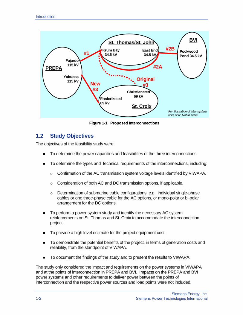
VIWAPA is proposing a transmission project that interconnects the electrical power systems on the islands of Puerto Rico (PREPA), St. Thomas and St. Croix (USVI), and the British Virgin Islands (BVI). VIWAPA’s proposed transmission project consists of three interconnections:
Interconnection 1: This approximately 50 mile (80 km) long Interconnection, between the Fajardo Substation in Puerto Rico and the Randolph Harley Power Plant (Krum Bay Substation) on St. Thomas, is envisaged as either an AC or DC link, with an expected power transmission capacity of 100 or 200 MW.
Interconnection 2: This Interconnection between St. Thomas and the BVI Island of Tortola consists of two sections. The first section (A) will consist of two AC submarine cables between the Krum Bay Substation and the East End Substation on St. Thomas, at a distance of about 20 miles. The second section (B), consisting of an AC submarine cable, will proceed from the East End Substation on St. Thomas to the Pockwood Pond Substation on Tortola of BVI, at a distance of about 17 miles.
Interconnection 3: The plan at the beginning of the study was to interconnection the Krum Bay Substation on St. Thomas and the Christiansted Substation on St. Croix by a 100 mile submarine cable link. The proposed cable route will reach water depths of 2,200 meter (7,200 feet), which lies outside the present state of the art in submarine cable designs and will require significant development and testing, including a full scale sea trial. During the study, a decision was made to change this interconnection to a 79 mile, 100 MW DC submarine cable link between the Yabucoa Substation in Puerto Rico and the Frederiksted Substation on St. Croix.
Study Objectives
The objectives of the feasibility study were:
To determine the power capacities and feasibilities of the three interconnections.
To determine the types and technical requirements of the interconnections, including:
o Confirmation of the AC transmission system voltage levels identified by VIWAPA.
o Consideration of both AC and DC transmission options, if applicable.
Siemens Energy, Inc. Siemens Power Technologies International vii

Executive Summary
o Determination of submarine cable configurations, e.g., individual single-phase cables or one three-phase cable for the AC options, or mono-polar or bi-polar arrangement for the DC options.
To perform a power system study and identify the necessary AC system reinforcements on St. Thomas and St. Croix to accommodate the interconnection project.
To provide a high level estimate for the project equipment cost.
To demonstrate the potential benefits of the project, in terms of generation costs and reliability, from the standpoint of VIWAPA.
To document the findings of the study and to present the results to VIWAPA.
Study Plan
To meet the project objective, Siemens PTI organized the study into a series of tasks, which consists of:
1) Kickoff conference call and data gathering - to initiate the study, gather all the necessary study data from VIWAPA and define the power transfer capability of each interconnection desired by VIWAPA, PREPA and BVI.
2) Study plan - to summarize the study scenarios, assumptions and criteria.
3) Submarine cable study - to define the basic parameters, such as the cable types, voltage levels and number of cables.
4) HVDC requirement study - to define the preliminary DC configuration, DC voltage, basic control and reactive power requirements and also to recommend the steady state and dynamic simulation models for use in the power system studies.
5) Interim Report 1 & technical presentation - to summarize the findings of the submarine cable and HVDC requirement studies and to discuss with VIWAPA the strategy for the next study tasks.
6) Power system studies - to test the feasibility of a selected set of potential interconnection options and identify the reinforcement requirements in the AC power system on St. Thomas and St. Croix to support the Project.
7) Interim Report 2 & technical presentation - to summarize the findings of the power system studies and to discuss with VIWAPA the strategy for the next study tasks.
8) Preliminary cost estimates - to provide approximate capital cost estimates for the major components in the interconnection project.
9) Potential benefits analysis - to demonstrate the potential benefits of the interconnections, in terms of costs of generation and reliability.
Siemens Energy, Inc. viii Siemens Power Technologies International

Executive Summary
10) Final report - to document the analyses performed in the study tasks and the comments received from VIWAPA and PREPA.
All the above tasks have been completed. The results from the Submarine Cable Study and the HVDC Requirement Study were documented in Interim Report #1 [1], last revised on May 30, 2011. Project Review Meeting #1 was held on February 11, 2011, during which the findings from Interim Report #1 were discussed and decisions on the subsequent tasks were made.
Results from the Power System Study were documented in Interim Report #2 [2], last revised on June 7, 2011. Project Review Meeting #2 was held on April 12, 2011, during which the findings from Interim Report #2 were discussed and decisions on the subsequent tasks were made.
Results from the Cost Estimate Study were documented in the Cost Estimate Study Task Report [3], last revised on August 1, 2011. Results from the Benefits Study were documented in the Benefits Study Task Report [4], last revised on June 30, 2011. Project Review Meeting #3 was held on June 17, 2011, during which the findings from these two tasks were discussed.
This Final Report provides a summary of the results from the various tasks. Technical details of the individual study tasks can be found in the respective interim and task reports and are not repeated in this document.
Conclusions
Provisional designs have been developed for the submarine cable links of the three interconnections.
Interconnection 1, between the Fajardo Substation in Puerto Rico and the Krum Bay Substation on St. Thomas, with a length of about 50 miles, has several feasible cable options:
o One three-core 115 kV AC 500 mm2 XLPE cable, for delivering 100 MW.
o A pair of 500 mm2 XLDC submarine cables, operating in a ± 80 kV symmetrical monopole VSC DC configuration, for delivering 100 MW.
o Three single-core 115 kV AC 800 mm2 XLPE cables, for delivering 200 MW.
o A pair of 500 mm2 XLDC submarine cables, operating in a ± 150 kV symmetrical monopole VSC DC configuration, for delivering 200 MW.
Interconnection 2A, between the Krum Bay and East End Substations on St. Thomas, will have two 20 miles long, 69 kV AC, three-core 150 mm2 XLPE submarine cables, for delivering 80 MW total.
Interconnection 2B, between the East End Substation on St. Thomas and the Pockwood Pond on Tortola, will have one 17 mile long, 69 kV AC, three-core 150 mm2 XLPE submarine cable of identical design to that proposed for Interconnection 2A, for delivering 40 MW.
Siemens Energy, Inc. Siemens Power Technologies International ix
Executive Summary
Interconnection 3, between the Yabucoa Substation in Puerto Rico and the Frederiksted Substation on St. Croix, will consist of a pair of DC 800 mm2 XLDC submarine cables, operating in a ± 80 kV symmetrical monopole VSC DC configuration, for delivering 100 MW. The tentative submarine cable route reaches an ocean depth of 5,640 feet, which is slightly greater than the current world record for submarine power cables of about 5,300 ft. held by the SAPEI Interconnection between Sardinia and Italian Mainland. It is recommended that the submarine cable design be subjected to laboratory testing and sea trial.
Interconnections 2A and 2B, because of the relatively moderate level of rated voltage and power capacity, will be AC transmission. Because of the longer distance (about 80 miles), only HVDC can be used for Interconnection 3. Both AC and DC transmission options are technically feasible for Interconnection 1.
Power system studies, consisting of steady state power flow, short circuit and dynamic simulation analyses were conducted on the interconnected power systems with all the proposed interconnections modeled. The upgrades required to accommodate the interconnections in the St. Thomas and St. Croix systems and at the points of interconnection in the PREPA and BVI systems were identified. Requirements within the PREPA and BVI systems to deliver the power between the points of interconnection and the respective power sources and load points were not included.
High level equipment cost estimates for the project, including all three interconnections and the associated AC system upgrades on St. Thomas and St. Croix were developed. These estimates do not include costs of upgrades in the PREPA and BVI system, such as AC system reinforcements and modifications to existing substations at the points of interconnection to accommodate the project. Only one submarine cable option has been recommended for each of interconnections 2 and 3. For Interconnection 1, the AC and DC submarine cable options at 100 MW and 200 MW of power transfer are all technically feasible. The relative economic ranking of the project with different options for Interconnection 1 is shown in the table below.
Table 1. Economic Ranking of Project with Different Interconnection 1 Options
Interconnection 1 Options 200 MW DC 200 MW AC 100 MW DC 100 MW AC
Relative Cost 116.4% 112.9% 104.4% 100.0%
The overall equipment cost estimates of the DC interconnection options are marginally higher than the corresponding AC options. The DC interconnection does provide some technical advantages, such as lower transmission losses during high level of power transfer, ability to control power flow and voltage and lower short circuit current impact. When lifetime costs are taken into consideration, the DC interconnection is more favorable. The HVDC system should be equipped with frequency control capability to maintain frequency in the VIWAPA system within acceptable levels during disturbances.
If the amount of power imported from PREPA on a regular basis is expected to be no more than 10 - 20 MW in the foreseeable future, then a transmission capacity of 100 MW for Interconnection 1 will be sufficient. Considering that the total demand on St. Thomas/St. John will reach about 110 MW by Year 2025 and the capacity of the cable link with BVI is 40
Siemens Energy, Inc. x Siemens Power Technologies International

Executive Summary
MW, the larger 200 MW link will provide enough import capability to serve all the loads in St. Thomas/St. John and BVI during an emergency. The incremental cost of going from 100 MW to 200 MW in Interconnection 1 is about 12% to 13% of the overall project equipment cost. A choice between the 100 MW and 200 MW interconnection options will be a decision of VIWAPA.
The interconnection with PREPA can provide benefits to the VIWAPA system in terms of fuel cost saving, improvement in reliability and reduction in CO2
emission. The degree of potential benefits that can be realized will depend on the amount and price of the power being imported.
Siemens Energy, Inc. Siemens Power Technologies International xi

Executive Summary
Siemens Energy, Inc. xii Siemens Power Technologies International
This page intentionally left blank.

Section
1 Introduction This document represents the Final Report for the Interconnection Feasibility Study that was performed by Siemens Energy, Inc., Siemens Power Technologies International (Siemens PTI) on behalf of the U.S. Virgin Islands Water and Power Authority (VIWAPA).
1.1 Project Background VIWAPA is proposing a transmission project that interconnects the electrical power systems on the islands of Puerto Rico (PREPA), St. Thomas and St. Croix (USVI), and the British Virgin Islands (BVI).
VIWAPA’s proposed transmission project consists of three interconnections:
Interconnection 1: This approximately 50 mile (80 km) long Interconnection between the Fajardo Substation in Puerto Rico and the Randolph Harley Power Plant (Krum Bay Substation) on St. Thomas, is envisaged as either an AC or DC link, with an expected power transmission capacity of 100 to 200 MW.
Interconnection 2: This Interconnection between St. Thomas and the BVI Island of Tortola consists of two sections. The first section (A) will be an AC submarine cable link between the Krum Bay Substation and the East End Substation on St. Thomas, at a distance of about 20 miles. The second section (B), which will consist of an AC submarine cable, will proceed from the East End Substation on St. Thomas to the Pockwood Pond Substation on Tortola of BVI, at a distance of about 17 miles.
Interconnection 3: The plan at the beginning of the study was to interconnection the Krum Bay Substation on St. Thomas and the Christiansted Substation on St. Croix by AC or DC submarine cable. The proposed cable route will reach water depths of 2,200 meters (7,200 feet), which lies outside the present state of the art in submarine cable designs and will require significant development and testing, including a full scale sea trial. During the study, a decision was made to change this interconnection to a 100 MW DC submarine cable link between the Yabucoa Substation in Puerto Rico and the Frederiksted Substation on St. Croix.
An overview of the interconnection project is illustrated in Figure 1-1.
Siemens Energy, Inc. Siemens Power Technologies International 1-1
Introduction
Siemens Energy, Inc. 1-2 Siemens Power Technologies International
St. Thomas/St. John
St. Croix
BVI
#2B Krum Bay
34.5 kV
Figure 1-1. Proposed Interconnections
1.2 Study Objectives The objectives of the feasibility study were:
To determine the power capacities and feasibilities of the three interconnections.
To determine the types and technical requirements of the interconnections, including:
o Confirmation of the AC transmission system voltage levels identified by VIWAPA.
o Consideration of both AC and DC transmission options, if applicable.
o Determination of submarine cable configurations, e.g., individual single-phase cables or one three-phase cable for the AC options, or mono-polar or bi-polar arrangement for the DC options.
To perform a power system study and identify the necessary AC system reinforcements on St. Thomas and St. Croix to accommodate the interconnection project.
To provide a high level estimate for the project equipment cost.
To demonstrate the potential benefits of the project, in terms of generation costs and reliability, from the standpoint of VIWAPA.
To document the findings of the study and to present the results to VIWAPA.
The study only considered the impact and requirements on the power systems in VIWAPA and at the points of interconnection in PREPA and BVI. Impacts on the PREPA and BVI power systems and other requirements to deliver power between the points of interconnection and the respective power sources and load points were not included.
PREPA
Fajardo115 kV
Pockwood Pond 34.5 kV
Frederiksted 69 kV
East End 34.5 kV #1
New #3
#2A
Yabucoa115 kV Original
#3 Christiansted
69 kV
For illustration of inter-system links only. Not to scale.

Section
2 Task 1 Kickoff Meeting & Data Gathering A Project Kickoff Meeting was held on October 29, 2010 in San Juan, Puerto Rico, attended by representatives from VIWAPA, IAES, PREPA, NREL, DOE and Siemens PTI. The interconnection scenarios, study data requirements and preliminary study schedule were discussed. The horizon year for the study was chosen to be 2025, after consideration of the possible in-service year of the interconnection project.
Subsequent to the Kickoff Meeting, VIWAPA and other parties provided the following study data:
Report for a Marine Desk Top Study, performed by Bioimpact, Inc. and Stearns Weaver Miller Weissler Alhadeff & Sitterson, P.A., dated November 2010. The document was provided on November 15-16, 2010.
Electrical parameters for the power systems on St. Thomas and St. Croix, including one-line diagrams of the as-planned systems, the 34.5 kV and 69 kV feeder impedances and present loads, the nameplate ratings and impedances of the transformers. Data were provided over a period of time from November 17, 2010 to January 18, 2011.
Preliminary information on the BVI system, showing the existing system peak load at 25 MW, the length of the St. Thomas - BVI submarine cable at about 5 miles and the desired capacity of the interconnection at 30 MW. The data were provided by VIWAPA on November 29, 2010.
High resolution bathymetry map showing the possible St. Thomas - St. Croix submarine cable route, which passes through an area with a maximum ocean depth of 2,200 meters. This data was provided by NREL on December 23, 2010.
Clarifications regarding the two existing 34.5 kV AC submarine cables between St. Thomas and St. John. This information was provided by VIWAPA on January 3, 2011.
Information on the existing power system in BVI, including a network single-line diagram, line lengths and impedances, transformer impedances, feeder loads and nameplate data of the generators. The data were provided over a period from January 27 to February 8 of 2011.
Updated information on the BVI power system, showing the existing system peak load at 33 MW, the length of the proposed St. Thomas - BVI submarine cable at 16 miles and the cable landing point at Pockwood Pond. These data were provided by VIWAPA on January 30, 2011.
Siemens Energy, Inc. Siemens Power Technologies International 2-1

Task 1 Kickoff Meeting & Data Gathering
Siemens Energy, Inc. 2-2 Siemens Power Technologies International
Additional data for the transformers, generators, circuit breakers and load shedding schemes in the St. Thomas and St. Croix power systems. These data were provided by VIWAPA over a period of time from February 14 to March 1 of 2011.
Power system model of the PREPA system for the years of 2011 and 2025, including power flow and dynamic simulation data, one-line transmission diagram, transmission system map and transmission planning criteria. The data were provided by PREPA over a period of time from February 9 to 25, 2011.
A map showing the possible Puerto Rico - St. Croix submarine cable route, with a maximum depth of 5,600 feet or 1,708 meter. This was provided by VIWAPA on February 24, 2011.
Proposed landing point in St. Croix of the submarine cable from PREPA. This information was provided by VIWAPA on March 3, 1011.
PREPA’s Transmission Planning Criteria. This document was provided by PREPA on March 29, 2011.
Generator data, load data and hourly load shape of the St. Thomas and St. Croix systems, for use in the Benefits Study. These data were provided by VIWAPA from March 8 to 10 of 2011.
Report for a Marine Desk Top Study of the proposed PREPA - St. Croix submarine cable route, performed by Bioimpact, Inc., dated April 2011. The document was provided by VIWAPA on April 11, 2011.
Clarifications of the transformer arrangements at the Harley Substation. This information was provided by VIWAPA on April 18, 2011 and was subsequently used to update the short circuit study.
Expected range of energy price for the PREPA - VIWAPA power transfer, for use in the Benefits Study. This data was provided on May 4, 2011.
Historical monthly peak and energy data, generator unit operating limits and availabilities for St. Thomas and St. Croix, for use in the Benefits Study. The data were provided over a period of time from May 17 to 26, 2011.

Section
3 Task 2 Study Plan
3.1 Study Tasks Siemens PTI developed a study plan to meet VIWAPA’s objectives. This plan consisted of ten tasks:
1) Kickoff conference call and data gathering - to initiate the study, gather all the necessary study data from VIWAPA and define the power transfer capability of each interconnection desired by VIWAPA, PREPA and BVI.
2) Study plan - to summarize the study scenarios, assumptions and criteria.
3) Submarine cable study - to define the basic parameters, such as the cable types, voltage levels and number of cables.
4) HVDC requirement study - to define the preliminary DC configuration, DC voltage, basic control and reactive power requirements and also to recommend the steady state and dynamic simulation models for use in the power system studies.
5) Interim Report 1 & technical presentation - to summarize the findings of the submarine cable and HVDC requirement studies and to discuss with VIWAPA the strategy for the next study tasks.
6) Power system studies - to test the feasibility of a selected set of potential interconnection options and identify the reinforcement requirements in the AC power system on St. Thomas and St. Croix to support the Project.
7) Interim Report 2 & technical presentation - to summarize the findings of the power system studies and to discuss with VIWAPA the strategy for the next study tasks.
8) Preliminary cost estimates - to provide approximate capital cost estimates for the major components in the interconnection project.
9) Potential benefits analysis - to demonstrate the potential benefits of the interconnections, in terms of costs of generation and reliability.
10) Final report - to document the analyses performed in the study tasks and the comments received from VIWAPA and PREPA.
Siemens Energy, Inc. Siemens Power Technologies International 3-1

Task 2 Study Plan
3.2 Study Assumptions Prior to the beginning of the Submarine Cable Study and HVDC Requirement Study, Siemens PTI sent VIWAPA a memorandum, dated November 24, 2010, summarizing the study assumptions, including the approximate generation capacity within each of the power systems being interconnected, the expected load demand in the horizon year, the desired maximum power transfer capability and the interconnection points of each interconnection and the approximate length of each submarine cable.
The assumptions at that time, shown below, were based on information gathered at the Kickoff Meeting, the data provided by VIWAPA up to that time, and additional information collected by Siemens PTI from other sources:
1) Submarine cables to be studied:
o Puerto Rico and Krum Bay, St. Thomas (PREPA - STT)
o Krum Bay, St. Thomas and Red Hook (East End Substation), St. Thomas (Krum Bay - Red Hook)
o Red Hook, St. Thomas and West End (Pockwood Pond Substation), Tortola (STT - BVI)
o Krum Bay, St. Thomas and Christiansted, St. Croix (STT - STX) (This was changed later to a PREPA - St. Croix interconnection).*
2) Existing generation capacity and load demand:
o PREPA: about 6,000 MW installed generation capacity, 3,500 MW peak load
o St. Thomas + St. John: 190 MW installed generation capacity, 86 MW peak load. This load includes about 10 MW on St. John.
o St. Croix: 105 MW installed generation capacity, 55 MW peak load.
o BVI, Tortola: peak load assumed to be no more than 25 MW. (The peak load was later modified to 33 MW and the generation capacity was provided later as 46.6 MW).*
3) Expected load growth in VIWAPA: 1.5% per year. The same growth rate was initially assumed for BVI. (BVI growth rate was later modified to 4% per year).*
4) The horizon year for the study is 2025. Load demand in 2025:
o St. Thomas including St. John: 110 MW
o St. Croix: 70 MW
o BVI, Tortola: not more than 32 MW. (This was later modified to 59.4 MW).*
Siemens Energy, Inc. 3-2 Siemens Power Technologies International

Task 2 Study Plan
5) Approximate lengths of cables:
o PREPA - STT: 50 miles
o Krum Bay - Red Hook: about 20 miles
o STT - BVI: about 5 miles (This was later modified to 17 miles).*
o STT - STX: 100 miles for route with maximum depth of no more than 2200 meters and 220 miles for route with maximum depth of no more than 1600 meters. (The latter route was found later to be in valid).*
6) Interconnection Transfer Capacity - As a starting point for the Submarine Cable Study and HVDC Study, the following alternatives for each cable were considered:
o PREPA - STT: 100 MW and 200 MW options
o Krum Bay - Red Hook: 50 MW (considering loads at East End and St. John and possible power export to BVI)
o STT - BVI: 30 MW
o STT - STX: 100 MW and 200 MW
7) AC or DC Transmission - The following alternatives were considered:
o PREPA - STT: AC and DC options
o Krum Bay - Red Hook: AC only
o STT - BVI: AC only
o STT - STX: DC only (Discussions of why AC is not feasible were provided later in the study report)
8) Type of DC - For both the PREPA - STT and STT - STX interconnections, the use of Voltage Source Converter based DC with polymeric extruded cable was recommended. The maximum transfer capacities identified above fit very well with modern VSC DC technology. Main advantages of this technology versus the conventional HVDC that could be critical for the Virgin Island interconnections are:
o Low sensitivity of the inverter terminal to characteristics of the AC power system at the receiving end
o VSC DC converters may operate at unity power factor
o VSC DC converters may participate in voltage control of the AC power system to which it is connected
o VSC DC can deliver power to isolated loads with no local generation
Siemens Energy, Inc. Siemens Power Technologies International 3-3

Task 2 Study Plan
o VSC DC can be used for black start of an islanded AC power system.
o VSC DC does not have the problem of DC current return encountered with conventional DC systems, which makes it more advantageous in terms of environmental concerns
9) Rated voltage of the DC interconnections - All existing VSC DC projects use symmetrical monopoles with rated DC voltage versus the neutral point of the monopole. Based on the modern VSC DC technology, the following DC voltages were suggested:
o PREPA - STT: 150 kV, at 100 MW or 200 MW
o STT - STX: 150 kV at 100 or 200 MW.
10) Rated voltage of the AC interconnections:
o PREPA - STT: 115 kV
o Krum Bay - Red Hook: 34.5 kV or 69 kV (to be compatible with AC system voltages in STT and STX)
o STT - BVI: 34.5 kV (This was later modified to 69 kV).*
* Some of the above parameters were modified in later stages of the study, based on updated information provided by VIWAPA. The updated information is reflected in subsequent study tasks.
3.3 Sizes of Power Systems Being Interconnected The existing power system in Puerto Rico has an installed capacity of approximately 5,830 MW and a peak load of about 3,350 MW, while the existing power system on St. Thomas has an installed capacity of 168 MW and a peak load of 88 MW, and the existing power system on St. Croix has an installed capacity of 123 MW and a peak load of 55 MW. The BVI system has an installed capacity of about 47 MW and a peak load of about 33 MW. A summary of the respective sizes of the current (year 2010) power systems is shown in Figure 3-1.
PREPA provided load and generation information for years 2010 and 2025. VIWAPA estimated that the annual growth of their load is about 1.5%. The only known generation addition is a combined cycle plant in the St. Croix system. BVI indicated that their existing annual load growth is about 4%, but did not provide a generation expansion plan. If the present load growth is projected to year 2025, the peak load in BVI will reach almost 60 MW, well beyond the existing installed capacity. In this study, some generation addition in BVI, sufficient to match the load growth, was assumed. A summary of the projected system sizes in the horizon year of 2025 is shown in Figure 3-2.
Siemens Energy, Inc. 3-4 Siemens Power Technologies International

Task 2 Study Plan
Figure 3-1. Approximate System Sizes in Year 2010.
PREPA Peak load: 3,354 MW Installed capacity: 5,831 MW
St. Thomas/St. JohnPeak load: 88 MW
Installed capacity: 167.7 MW
St. Croix Peak load: 55 MW
Installed capacity: 122.6 MW
BVI Peak load:
33 MW Installed capacity: 46.6 MW
PREPA Peak load: 4,152 MW Installed capacity: 6,419 MW
St. Thomas/St. JohnPeak load: 110 MW
(1.5% growth) Installed capacity: 167.7
MW
St. Croix Peak load: 68.8 MW
(1.5% growth) Installed capacity: 138.6
MW
BVI Peak load:
59.4 MW (4% growth) Installed
capacity: 69.4 MW (assumed)
Figure 3-2. Projected System Sizes in Horizon Year of 2025
Siemens Energy, Inc. Siemens Power Technologies International 3-5

Task 2 Study Plan
Siemens Energy, Inc. 3-6 Siemens Power Technologies International
This page intentionally left blank.
Section
4 Task 3 Submarine Cable Study
4.1 Task Objective The Submarine Cable Study required the development of optimum technical and cost effective HVAC and HVDC submarine cable solutions for the delivery of electrical power from the island of Puerto Rico to the USVI with additional submarine cable links within the USVI and between the USVI and the BVI. The following three interconnections were specified in the VIWAPA’s RFP for this study, namely:
INTERCONNECTION 1: Puerto Rico to St. Thomas (PREPA – STT)
This approximately 50 mile (80 km) long Interconnection between Fajardo, Puerto Rico and Krum Bay, St. Thomas is envisaged as either a 115 kVAC or an HVDC link with a power transmission capacity of 100 or 200 MW. The HVDC submarine cable operating voltage was not specified and will be determined during the course of the Study.
INTERCONNECTION 2: St. Thomas to Tortola (BV))
This Interconnection between St. Thomas and the BVI Island of Tortola consists of two sections. The first section (A) will be an AC submarine cable link between the Krum Bay and East End Substations in St. Thomas, a distance of approximately 20 miles (32 km). The second section (B) will proceed from East End Substation to Pockwood Pond Substation in the BVI Island of Tortola, a distance of approximately 17 miles (27 km). The rated power transmission capacity for both links will be 50 MW.
INTERCONNECTION 3: Krum Bay, St. Thomas to Christiansted, St. Croix (STT – STX)
This Interconnection which will link St. Thomas with the Island of St. Croix, a distance of approximately 100 miles (160 km) will be configured as an HVDC submarine cable link. The rated dc voltage and power transmission capacity are to be determined during the course of the Study.
4.2 Study Approach The state of the art in submarine cable technology was reviewed, with the objective of providing background on the types of submarine power cable currently available and their ranges of application in terms of voltage, power transmission capacity, maximum transmission distance and maximum water depth etc. Based on this information, a selection
Siemens Energy, Inc. Siemens Power Technologies International 4-1
Task 3 Submarine Cable Study
was made of the most appropriate submarine cable types for each of the proposed submarine cable interconnections.
Following selection of the most appropriate cable types, detailed provisional designs for each of the three specified submarine cable Interconnections were developed. These designs have been selected to comply (as far as is practicable) with existing and applicable International Standards and Recommendations or with generally accepted industry practice.
Reliability issues were discussed, including information on the intrinsic reliability of submarine cables against failures due to inherent defects in the cable system itself as well as threats to the integrity of the cable systems posed by third party marine users.
High level budgetary cost estimates for the supply and installation of the various HVAC and HVDC cable system designs proposed were provided. These were based on project experience, recent private communications from the industry and information available on the Internet.
Since the desk top study indicates a significant number of power and telecommunication cables in the region, the installation methodology at the crossing points was also discussed.
4.3 Preliminary Findings A Draft Interim Report #1 [1] containing the results of the Submarine Cable Study was issued on January 27, 2011.
Three of the proposed submarine cable links, namely: 1) Puerto Rico to St. Thomas, 2) Krum Bay to East End, St. Thomas and 3) East End, St. Thomas to Pockwood Pond, Tortola, can be considered to be within the present state of the art. On the other hand, the deep water (maximum depth of 2,200 m) interconnection between St. Thomas and St. Croix involves tensile loads during cable laying that are in excess of the current design maxima for conductors with joints and armor wires by approximately 30%. This does not mean that this interconnection is not technically feasible, since it is accepted that current design maxima are conservative. However, it does mean that the proposed submarine cable designs would need to be developed and type-tested mechanically according to Electra 171 (1997) and electrically according to CIGRE Technical Bulletin No. 219 (2003). In addition to laboratory testing, it would also be advisable to conduct a sea trial, as recommended by Electra 171, since laying conditions differ significantly from earlier established practice.
The following summarizes the cables selected initially for the three interconnections.
4.3.1 Interconnection 1: Puerto Rico to St. Thomas
The desired power transmission levels of 100 MW and 200 MW can be achieved either by submarine cable links operating at 115 kV AC or at ± 80 kV DC and ± 150 kV DC, respectively. Installed cable budgetary costs favor the HVDC options by approximately 10% and 20%, respectively, for the 100 MW and 200 MW power levels. The cable system losses are also considerably less, at between 25 and 50% of the equivalent HVAC links. When the cost of VSC converters is taken into account, there is little difference between the HVAC and HVDC system options.
Siemens Energy, Inc. 4-2 Siemens Power Technologies International

Task 3 Submarine Cable Study
4.3.2 Interconnection 2A: Krum Bay to East End, St. Thomas
The relatively short length (20 miles) makes a 3-core XLPE submarine cable the obvious choice for this Interconnection. 69 kV AC was selected in preference to 35 kV AC, since the latter would have required a conductor size (> 1200 mm2) outside of the normal range for 3-core XLPE cables at this voltage rating, as well as a significant cost premium.
4.3.3 Interconnection 2B: East End, St. Thomas to Pockwood Pond, Tortola
A 3-core 69 kV AC XLPE cable of identical design to that proposed for Interconnection 2A was also selected for this Interconnection, since the only difference between the two Interconnections was the route length, 27 km (17 miles) in the present case, compared with 32 km (20 miles) in the case of Interconnection 2A.
The only alternative for both Interconnections would have been a similar cable design with the XLPE insulation, replaced by wet-design EPR with the possibility of some Ex. Works cost savings.
4.3.4 Original Interconnection 3: St. Thomas to St. Croix
This Interconnection, with water depths up to and including 2,200 m, lies outside the present state of the art and will require significant development and testing, which should include a full scale sea trial. This will take between one and two years to complete, once initiated (difficult with the present buoyant market for submarine cables) and would not cost less than $5 million USD. Therefore, prospects for the implementation of this Interconnection in the foreseeable future look rather bleak.
4.4 Changes to Interconnections 2A and 2B The preliminary designs of the submarine cables from the Draft Interim Report #1 [1], dated January 27, 2011, were used for modeling the interconnections in the Power System Studies in Task 6. Steady state power flow analysis showed that, when the AC submarine cable between East End Hook on St. Thomas and Tortola of BVI (referred to as Interconnection 2B) is delivering 50 MW to Tortola, the AC submarine cable between the Krum Bay Substation and the East End Substation (Interconnection 2A) will be loaded above its rating of 50 MW. Furthermore, heavy power transfers from west to east in the 34.5 kV network on St. Thomas will also increase the loading of the Krum Bay - East End submarine cable, especially during outage of a 34.5 kV circuit on the island (N-1 condition). The cable for Interconnection 2A would have to be sized at about 80 MVA. The design of this cable was updated accordingly.
The power system studies also showed that an outage of the submarine cable link between Krum Bay and East End (Interconnection 2A) would transfer the entire submarine cable load onto the existing 34.5 kV network on St. Thomas and overload the underground cables on the island. VIWAPA, therefore, suggested to replace the single 80 MVA submarine cable link with two 40 MW submarine cables. Implementation of this modification also requires the East End, St. Thomas - Pockwood Pond, Tortola submarine cable (Interconnection 2B) to be tripped immediately whenever one of the two Krum Bay - East End (Interconnection 2A) cables is outaged. Furthermore, VIWAPA recommended limiting the power transfer from St. Thomas to Tortola (via Interconnection 2B) to no more than 40 MW. The revised designs of
Siemens Energy, Inc. Siemens Power Technologies International 4-3

Task 3 Submarine Cable Study
the submarine cables for Interconnections 2A and 2B were documented in Addendum 2 to the Submarine Cable Study Report of the Interim Study Report #1 [1], reissued on May 31, 2011.
4.5 Revised Interconnection 3: Yabucoa, Puerto Rico to Frederiksted, St. Croix
During the Project Review Meeting #1 held on February 11, 2011, when the results of the Submarine Cable Study and the HVDC Requirements Study were discussed, it was decided not to proceed with the proposed interconnection between St. Thomas and St. Croix. The decision was taken because: (a) the 7,200 ft. maximum water depth along the proposed cable route was significantly in excess of the current world record of 5,300 ft. and (b) the prospect of developing a practical cable solution could not be confirmed by potential suppliers. In view of the uncertainty of a positive outcome, VIWAPA decided to investigate, as an alternative, a direct interconnection between Puerto Rico and St. Croix.
The provisional design of the submarine cable for this new Interconnection 3 between Puerto Rico and St. Croix was documented in Addendum 1 to the Submarine Cable Study Report of the Interim Study Report #1 [1], reissued on May 31, 2011. The deep-water marine route between Puerto Rico and St. Croix reaches a maximum of about 5,640 ft. (1,720 m), which is slightly greater than the current world record for submarine power cables of about 5,300 ft., held by the SAPEI Interconnection between Sardinia and Italian Mainland. The fact that the mechanical design proposed for this interconnection has been based on the same technology as that used for the SAPEI cable, together with the fact that the increase in water depth can be considered incremental, should provide a high probability for a successful cable laying operation. However, the proposed submarine cable design would need to be subjected to laboratory testing and sea trial, as mentioned above for the St. Thomas - St. Croix submarine cable.
Also included in the Addendum was a 400 MW submarine cable between Puerto Rico and St. Croix. Since the projected demand in the St. Croix system will be no more than 70 MW by the study horizon of Year 2025, the larger cable capacity is meant to support a possible future interconnection between St. Croix and the Island of Nevis, from which geothermal power may be developed for export. This potential interconnection with Nevis and the use of the 400 MW submarine cable between Puerto Rico and St. Croix were not considered in the other tasks of the VIWAPA Interconnection Feasibility Study.
4.6 Submarine Cable Cost Estimates High level cost estimates for the submarine cables selected for the three interconnections were developed, based on prior high voltage submarine cable project experience, on private communications with industry specialists, and on project information available on the Internet. Cable cost Ex. Works, transport (assumed to be from Europe) and laying were considered. The budgetary estimates did not include costs for marine survey, utility line crossings, route clearance operations, special shore end works such as horizontal directional drilling or special protections.
The costs for cable burial / alternative protection have been added for the entire marine routes for Interconnections 1 and 2. Because of the very deep water along most of the
Siemens Energy, Inc. 4-4 Siemens Power Technologies International
Task 3 Submarine Cable Study
marine route of Interconnection 3, cable burial has only been considered necessary over a distance of 10 km at the shore ends of the route. The costs of the HVDC systems associated with the DC transmission links are not included in the above estimates.
For each of the single-core AC or DC cable interconnections, the estimate includes a fiber optic cable, consisting of 12 fiber pairs, that is transported, installed and buried bundled with the HV cable. For the 3-core AC power cables, the estimate includes the integral fiber optic elements. Details of the cost estimates are shown in Interim Study Report #1. [1]
Siemens Energy, Inc. Siemens Power Technologies International 4-5

Task 3 Submarine Cable Study
Siemens Energy, Inc. 4-6 Siemens Power Technologies International
This page intentionally left blank.

Section
5 Task 4 HVDC Requirement Study
5.1 Task Objective The objectives of the HVDC Requirement Study Task were:
To review of the state-of-the-art technologies in HVDC transmission
To recommend the HVDC circuit configurations for any or all of the three interconnections, if applicable
To identify the reactive power requirements associated with the HVDC interconnections.
To identify any necessary AC/DC system enhancements associated with the interconnections and describe any necessary control features and strategy
To derive preliminary modeling parameters for the recommended HVDC system(s) for use in the Power System Studies
5.2 Study Approach Characteristics of the Conventional HVDC and Voltage Source Converter (VSC) HVDC technologies were reviewed.
Recommendations for the HVDC systems associated with two of the interconnections, namely, between Puerto Rico and St. Thomas, and between St. Thomas and St. Croix, were provided. An overview of the typical equipment needs at a HVDC terminal was discussed. The per kW cost of the conventional and VSC HVDC systems were compared, including an approximate cost breakdown among the major HVDC system components.
Preliminary power flow and dynamic simulation models for the HVDC interconnections between Puerto Rico and St. Thomas and between St. Thomas and St. Croix were prepared for use in the Power System Study Task.
5.3 Preliminary Findings Results of the HVDC Requirement Study were documented in the Interim Study Report #1 [1], Part II.
Siemens Energy, Inc. Siemens Power Technologies International 5-1
Task 4 HVDC Requirement Study
Reviews of different HVDC technologies and the results from the Submarine Cable Study, suggested that the VSC HVDC may be used for the following two interconnections:
Interconnection 1: Between Fajardo, Puerto Rico and Krum Bay, St. Thomas, at 100 or 200 MW
Original Interconnection 3: Between Krum Bay, St. Thomas and Christiansted, St. Croix, at 100 or 200 MW.
Because of the cost advantage, AC transmission is recommended for the other interconnections:
Interconnection 2A: Between Krum Bay, St. Thomas and East End, St. Thomas
Interconnection 2B: Between East End, St. Thomas and Pockwood Pond, Tortola, BVI
5.3.1 VSC HVDC
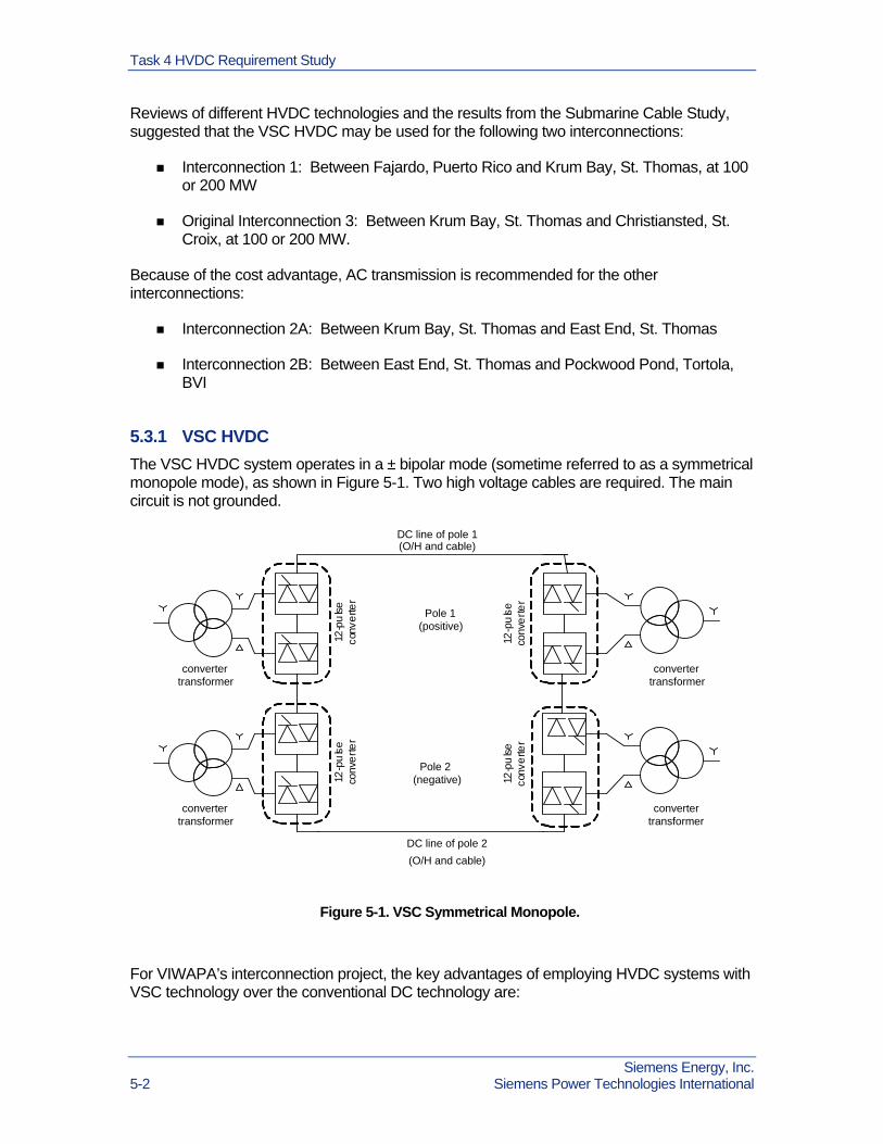
The VSC HVDC system operates in a ± bipolar mode (sometime referred to as a symmetrical monopole mode), as shown in Figure 5-1. Two high voltage cables are required. The main circuit is not grounded.
convertertransformer
12-p
uls
eco
nve
rter
convertertransformer
12-p
uls
eco
nve
rte
rDC line of pole 1(O/H and cable)
convertertransformer
12-p
uls
eco
nve
rte
r
convertertransformer
12-p
uls
eco
nve
rter
Pole 1(positive)
Pole 2(negative)
DC line of pole 2
(O/H and cable)
Figure 5-1. VSC Symmetrical Monopole.
For VIWAPA’s interconnection project, the key advantages of employing HVDC systems with VSC technology over the conventional DC technology are:
Siemens Energy, Inc. 5-2 Siemens Power Technologies International

Task 4 HVDC Requirement Study
Low sensitivity of the inverter terminal to the characteristics of the AC power system at the receiving end.
VSC converters may participate in voltage control of the AC power system to which it is connected.
HVDC with VSC can deliver power to isolated loads with no local generation.
HVDC with VSC can be used for black start of an islanded AC power system.
HVDC systems with VSC do not have the issue related to DC current return that is often found in conventional DC systems, which makes it more advantageous in terms of environmental concerns.
Parameters for the two proposed HVDC interconnections were prepared for use in power flow and dynamic simulation analyses.
5.4 Modifications to Interconnection 3 During the Project Review Meeting #1, it was decided to change the St. Thomas - St. Croix interconnection to a PRPEA - St. Croix interconnection. VIWAPA requested Siemens PTI to develop provisional submarine cable designs and budgetary costs for a 100 MW and a 400 MW interconnection. The 100 MW interconnection is related to the power requirement of the St. Croix system, while the 400 MW interconnection is related to a probable future link from St. Croix to the Island of Nevis.
The VSC HVDC symmetrical monopole configuration is recommended for the 100 MW PREPA - St. Croix interconnection. Steady state and dynamic simulation models for this interconnection were prepared for use in the Power System Study.
The 400 MW cable link that is meant to support a potential interconnection with Nevis is not part of the present VIWAPA Interconnection Feasibility Study. Nevertheless, a discussion of the possible HVDC configuration for linking the PREPA, St. Croix and Nevis power systems, including the use of multi-terminal HVDC system, is provided in Addendum 1 to the HVDC Requirement Study Report in Interim Study Report #1 [1], reissued on May 31, 2011.
5.5 Conclusions The VSC HVDC systems may be used for the interconnections between Puerto Rico and St. Thomas (Interconnection 1) and between Puerto Rico and St. Croix (Interconnection 3).
For Interconnection 1, the primary windings of the converter transformers on the PREPA power system side will be connected to the 115 kV AC network at Fajardo; on the St. Croix side, the converter transformers will be connected to a new 69 kV AC station at Krum Bay.
For Interconnection 3 at 100 MW, the primary windings of the converter transformers on the PREPA power system side will be connected to the 115 kV AC network at Yabucoa; on the St. Croix side, the converter transformers will be connected to the 69 kV AC network at Frederiksted. For the 400 MW interconnection, a higher voltage substation, probably at 230 kV AC, may be developed on both the PREPA and St. Croix sides.
Siemens Energy, Inc. Siemens Power Technologies International 5-3

Task 4 HVDC Requirement Study
Siemens Energy, Inc. 5-4 Siemens Power Technologies International
Both the AC and DC transmissions are feasible options for Interconnection 1, which is only about 50 miles long. The total price of both options will be compared later in the Cost Estimate Study Task. Because of the cost of the HVDC converters, the DC option will likely be more expensive. However, an interconnection with HVDC can provide power control, limit the short circuit impact and aid in system stability. These are some of the advantages over the AC transmission option that will be taken into consideration in the comparison of the options.
The reinforcements in the AC power systems that are required by the interconnection project are identified in the Power System Study Task. Because of the voltage control capability of the VSC HVDC system, the need for additional reactive compensation at the converter terminals will be limited. Some AC filters may be required.
Because these two proposed interconnections will be linking the much larger PREPA system with the smaller systems on St. Thomas and St. Croix, it would be beneficial to incorporate frequency control capability in the HVDC systems on the US Virgin Islands side to respond to real power disturbances in the two smaller systems.

Section
6 Task 5 Interim Report #1
6.1 Summary Results of the Submarine Cable Study in Task 3 and the HVDC Requirements Study in Task 4 were documented in a Draft Interim Report #1 [1] on January 2011 and submitted to VIWAPA for review.
A Project Review Meeting #1 was held in San Juan, Puerto Rico, on February 11, 2011. The meeting was attended by representatives from VIWAPA, IAES, PREPA, BVI, DOE and Siemens PTI. Technical presentations were made by Siemens PTI and interspersed with questions and answers.
Baldwin Lam gave a summary of the study parameters that were provided by VIWAPA or assumed by Siemens PTI, including the lengths and desired capacities of the three interconnections and the MW sizes of the power systems on Puerto Rico, St. Thomas/St. John, St. Croix and BVI.
Graham Lawson gave an overview of submarine cable designs and the recommended AC and DC cables for the three interconnections.
Yuriy Kazachkov summarized the results from the HVDC Requirements Study.
Minutes were circulated by VIWAPA after the meeting. VIWAPA agreed to the results of the study in general. BVI provided updated information on its present installed generation capacity and peak load. VIWAPA recommended that the maximum capacity of Interconnection 2B between St. Thomas and Tortola be limited to 50 MW. Siemens PTI agreed to update the submarine cable design for the interconnection with BVI accordingly.
Assumptions for the next task, the Power System Study, were discussed. Below were decisions that came as a result:
PREPA, VIWAPA, BVI were to provide additional data to Siemens PTI for the Power System Study.
PREPA stated that an interconnection between Puerto Rico and the US Virgin Islands using AC transmission would not be acceptable.
For the Puerto Rico - St Thomas interconnection, the power system study would first evaluate the AC option on a high level for potential stability and/or short circuit issues to see if it is feasible.
Siemens Energy, Inc. Siemens Power Technologies International 6-1

Task 5 Interim Report #1
Siemens Energy, Inc. 6-2 Siemens Power Technologies International
The study of the interconnection between St. Thomas and St. Croix would be replaced by a DC interconnection between Puerto Rico and St. Croix, due to concern with the water depth along the proposed cable route for the former interconnection.
Graham Lawson would look into the test limits of water depths of submarine cables, since the deepest water depth for the potential cable route between Puerto Rico and St. Croix is about 1,800 feet.
A desk top marine study would be needed for the Puerto Rico to St. Croix cable route.
St. Thomas - Tortola Interconnection would be rated at 50MW and would have a length of 17 miles, based on latest information received from BVIEC.
The Power System Study will be conducted with all of the interconnections in service.
Also discussed was a possible routing of the submarine cable between Puerto Rico and St Thomas through Culebra. This alternative route would be investigated separately by VIWAPA and IAES.
The overall Project schedule was discussed. The aim was to complete all study tasks by June 30, 2011. The suggestion was to begin the Cost Estimate Study in Task 7 and the Benefits Study in Task 8 earlier than originally scheduled, pending availability of study data.
After the meeting, the results of the Submarine Cable Study and HVDC Requirement Study were updated to reflect the discussions at the meeting and a revised Interim Report #1 [1] was issued on May 31, 2011.

Section
7 Task 6 Power System Study
7.1 Task Objective The objectives of the power system study were to:
Evaluate the performance of the interconnected power systems
Identify necessary AC system reinforcements on St. Thomas and St. Croix of the USVI and at the points of interconnection in the PREPA and BVI systems.
The power system study included the following components:
Modeling of the project
Steady state assessment
Stability assessment
Short circuit assessment
7.2 Study Approach The basic assumption was that the existing power system and the planned power system for the horizon year on St. Thomas and St. Croix are compliant with VIWAPA’s planning criteria. Hence, the power system study focused on potential issues associated with the interconnection project and was not meant for developing a new transmission plan for the St. Thomas and St. Croix system without the interconnection project. It was also assumed that the PREPA and BVI systems already have their own reinforcement plans to accommodate the expected levels of power imports/exports. Hence, for the PREPA and BVI systems, the Power System Study was limited to identifying major equipment requirements, such as reactive compensation, at the terminals of the interconnection project.
A set of representative scenarios was selected for the horizon year of 2025 in the study, including different power transfer levels of the interconnection project, different thermal commitment and dispatch in the VIWAPA system, and peak and light load conditions. These scenarios were meant to capture major reliability problems, if any, in the power system study. In several scenarios, the load growths in the St. Thomas or St. Croix system were extrapolated beyond Year 2025 to identify equipment requirements when the transfers across the interconnections were at the respective desired maxima.
Siemens Energy, Inc. Siemens Power Technologies International 7-1

Task 6 Power System Study
Steady state analysis, short circuit analysis and stability analysis were performed to ensure that the interconnection project meets reliability criteria, including system adequacy and security. The interconnected systems were tested under normal (all major transmission element in service) and single contingency (with one major transmission element out of service) conditions. The latter is commonly referred to as N-1 condition. Existing normal and emergency ratings of transmission circuits and transformers were used to identify potential thermal overloading issues. Bus voltages were maintained between +/- 5% of nominal during normal and single contingency conditions.
7.3 Findings Results of the Power System Study were documented in Interim Study Report #2 [2] and discussed during the Interim Meeting #2. The study concluded that the proposed cables interconnecting the PREPA to USVI and BVI systems are feasible. However, some upgrades will be needed in the USVI, PREPA and BVI systems. After the meeting, several telephone discussions were held between VIWAPA and Siemens PTI to review the thermal loading issues on St. Thomas and St. Croix and identify possible system reinforcements. The power system study results were updated and a revised Interim Study Report #2 [2] was subsequently issued.
7.3.1 Upgrades in St. Thomas System
Initial results showed that, if the AC submarine cable between East End on St. Thomas and Pockwood Pond, Tortola of BVI (referred to as Interconnection 2B) is delivering 50 MW to Tortola, the AC submarine cable between Krum Bay and East End (Interconnection 2A) will be loaded above its initial rating of 50 MW. Furthermore, heavy power transfers from west to east in the 34.5 kV network on St. Thomas will also increase the loading of the Krum Bay - East End submarine cable, especially during outages of 34.5 kV circuits on the island. Hence, the cable for Interconnection 2A had to be resized at about 80 MVA. The design of this cable was updated accordingly.
Subsequent power system studies showed that an outage of the 80 MVA submarine cable link between Krum Bay and East End (Interconnection 2A) would transfer the submarine cable load onto the existing 34.5 kV network on St. Thomas. VIWAPA, therefore, suggested to replace the single 80 MVA submarine cable link with two 40 MW submarine cables. Implementation of this modification also requires the East End, St. Thomas - Pockwood Pond, Tortola submarine cable (Interconnection 2B) to be tripped immediately whenever one of the two Krum Bay - East End (Interconnection 2A) cables is outaged. Furthermore, the maximum power transfer from St. Thomas to Tortola (via Interconnection 2B) will be limited to no more than 40 MW.
If there is only one 69/34.5 kV transformer at Krum Bay, its outage will cause thermal overloads and low voltages in the St. Thomas 34.5 kV system during high power import from PREPA, when many of the thermal units at the Harley Generation Station on St. Thomas are turned off. This contingency will result in the St. Thomas loads being served mostly through the Interconnection 2A submarine cables and the East End 69/34.5 kV transformer. A possible solution is to install two 69/34.5 kV transformers at Krum Bay.
Siemens Energy, Inc. 7-2 Siemens Power Technologies International

Task 6 Power System Study
Outage of one of the two Krum Bay – Long Bay 34.5 kV circuits on the island will overload the remaining circuit, even without the interconnection project, These 34.5 kV circuits need to be upgraded, either by replacing the existing underground cables or adding a third cable.
Low voltage problems were found in the scenario when St. Thomas is importing 200 MW from RPEPA via an AC interconnection. These problems can be addressed by adding 20 Mvar of shunt capacitors (either as two 10 Mvar banks or four 5 Mvar banks) at the East End 34.5 kV substation.
Stability analysis indicates that when a large amount of power is being imported from PREPA across Interconnection 1, the outage of the interconnection will result in significant underfrequency load shedding in both the St. Thomas and BVI systems. Therefore, when VIWAPA and BVI systems are interconnected by Interconnection 2B, their underfrequency load shedding settings will have to be coordinated. The St. Thomas system is stable for most of the simulated disturbances for all the interconnection options studied.
When a fixed amount of power is being imported from PREPA through the DC interconnection, the outage of a generator, load or the interconnection 2B to BVI will result in significant frequency excursion in the St. Thomas system. HVDC systems can be designed to have frequency control capability and can react to such disturbances by promptly adjusting the level of power transfer across the interconnection, as long as there is sufficient regulating capability on the PREPA side and reserve capacity in the submarine cables. This will be similar to the situation when the St. Thomas system is interconnected to PREPA via an AC cable, during which the system frequency of St. Thomas will follow that of the much larger PREPA system. In this way, both the AC and DC interconnection options can provide frequency control.
One advantage of the DC interconnection option is that it provides some electrical separation between the PREPA and VIWAPA systems. Faults occurring on the PREPA side will have much less impact on the fault currents observed in the St. Thomas system when the two systems are interconnected via DC rather than AC transmission. Short circuit analysis indicates that the introduction of Interconnections 1 and 2 will increase the short circuit currents observed in the St. Thomas power system. The computed short circuit currents are higher when AC transmission is used in Interconnection 1 instead of DC. In particular, the short circuit current at the Krum Bay 13.8 kV bus will exceed the existing circuit breaker duty when St. Thomas is interconnected with PREPA via AC transmission.
7.3.2 Upgrades in St. Croix System
Significant steady state thermal and voltage issues were found when St. Croix is importing 100 MW via Interconnection 3 from PREPA. The proposed interconnection point on St. Croix is near the Frederiksted 69 kV AC Substation on the western side of the island, while most of the loads and thermal generation are connected to the existing Richmond Substation on the eastern side. If the loads are supplied entirely by power imported from PREPA at Frederiksted, the 69 kV circuits between Frederiksted and Richmond will be severely overloaded. A possible solution to these problems is to:
Upgrade the ratings of the 69 kV circuits between Midland and Richmond (Circuit 1) to at least 67 MVA, between Frederiksted and Richmond (Circuit 2) to at least 105 MVA, and between Frederiksted and Midland (Circuit 5) to at least 101 MVA.
Siemens Energy, Inc. Siemens Power Technologies International 7-3

Task 6 Power System Study
Add 20 Mvar of shunt capacitors (as five 4 Mvar banks) at the Richmond 15 kV substation, if not enough thermal units are online at the Richmond Plant to provide voltage support.
Another possible solution is to
Replace Circuit 2, Richmond-Frederiksted, with two 69 kV, 48 MVA underground cables.
Replace Circuit 5, Frederiksted-Midland, with two 69 kV, 43 MVA underground cables.
The stability analysis shows that, although the St. Croix system remains stable following all the disturbances simulated, load shedding occurs during many disturbances, particularly those involving generator outages in St. Croix or 3-phase faults near the interconnection on the PREPA and near several St. Croix substations. Some of the underfrequency load shedding caused by generator outages can be avoided by implementing frequency control in the HVDC link.
7.3.3 System upgrades in PREPA System
For both the AC and DC 100 MW options for Interconnection 1, no thermal and voltage problems were found on the PREPA side. For both the AC and DC 200 MW options for Interconnection 1, the following system problems were identified:
The outage of the Fajardo – Daguao 115 kV line will cause a low voltage problem when 200 MW is being exported to St. Thomas and 100 MW is being exported to St. Croix. The voltage problem can be addressed by adding 20 Mvar of shunt capacitors at Fajardo 115 kV bus.
The outage of the Fajardo – Palmer 115 kV line will load the Daguao – Rio Blanco 115 kV line to about 106% (246 MVA) of its normal rating (231 MVA). The emergency rating of this line will need to be reviewed by PREPA. Also, 15 Mvar of shunt capacitors will be needed at the Fajardo 115 kV bus to resolve a voltage problem found in the 200 MW AC interconnection option.
The outage of the Daguao – Rio Blanco 115 kV line will load the Fajardo – Palmer 115 kV line to about 104% (241 MVA) of its normal rating (231 MVA). The emergency rating of this line will need to be reviewed by PREPA. Also, 60 Mvar of shunt capacitors will be needed at the Fajardo 115 kV bus to resolve a voltage problem found in the 200 MW AC interconnection option.
In summary, to accommodate the interconnection, up to 60 Mvar of shut capacitors will be needed at the Fajardo 115 kV bus, if the interconnection with St. Thomas is a 200 MW AC transmission. This is not needed with other interconnection options.
Two 115 kV circuits near the point of interconnection will become overloaded during single contingency condition, if the interconnection with St. Thomas is a 200 MW AC or DC transmission. The emergency ratings of these circuits need to be reviewed by PREPA for possible upgrades.
Siemens Energy, Inc. 7-4 Siemens Power Technologies International

Task 6 Power System Study
The substations at Fajardo and Yabucoa will need to be expanded to accommodate the respective interconnections.
7.3.4 System upgrades in BVI System
The BVI system will encounter severe low voltage problems if the loads are to be supplied mostly by power imported from PREPA or the USVI and a significant number of local generators are turned off-line. Reactive compensation can be provided in the form of power factor correction shunt capacitors near the loads or at selection locations in the network. For this study, 15 Mvar of shunt capacitors were tentatively added at the Pockwood Pond 34.5 kV bus to maintain adequate voltage. Since power factors of the loads were not provided by BVI, assumed values were used in the study. Hence, the actual reactive compensation needs in the BVI system will require further investigation, outside the scope of this study.
Steady state contingency analysis showed that, prior to the interconnection project, one Pockwood Pond – Long Bush cable would load to 185% of its normal 25 MVA rating when the other parallel cable is outaged. Hence, the BVI system will need some system reinforcements to accommodate load growth.
Stability simulation models of the BVI generators were not available for the study, so data were assumed using generic models and parameters for typical diesel generators. The dynamic simulation results showed that the BVI generators will lose synchronism with St. Thomas following some three-phase faults in the St. Thomas system, especially in the scenarios with many generators online in BVI and 200 MW was being import from PREPA via Interconnection 1. This could be an inherent characteristic of the BVI system, but may also be aggravated by the interconnection with larger power systems.
7.4 Summary Results of the power system study, including the identified equipment related to each of the interconnections and the necessary upgrades in the interconnecting AC power systems were used in the subsequent study task to develop cost estimates for the interconnection project.
Siemens Energy, Inc. Siemens Power Technologies International 7-5

Task 6 Power System Study
Siemens Energy, Inc. 7-6 Siemens Power Technologies International
This page intentionally left blank.

Section
8 Task 7 Interim Report #2
8.1 Summary Results of the Power System Study in Task 6 were documented in a Draft Interim Report #2 [2] on March 29, 2011 and submitted to VIWAPA for review.
A Project Review Meeting #2 was held in San Juan, Puerto Rico on April 12, 2011. The meeting was attended by representatives from VIWAPA, IAES and PREPA. Siemens PTI and representatives from DOE participated via web and telephone conference. Siemens PTI was represented by Baldwin Lam, Yuriy Kazachkov, Lengcheng Huang and Donna Anderson. Baldwin Lam summarized the study assumptions and results from the Power System Study. The presentation was accompanied by questions and answers. Minutes of the meeting were circulated by VIWAPA after the meeting.
The project schedule was discussed. Below are items that were discussed and decisions that came as a result:
PREPA stated that the interconnection point for the Puerto Rico-St Croix interconnection would not be located at Daguao 115 kV Substation, as previously indicated, but would be at Yabucoa 115 kV Substation.
VIWAPA stated that, based on future projections, 3-5 MW of wind generation per island should be considered in the Benefits Study Task.
The power purchase agreement was discussed. The initial idea was to have 20 MW, 7X24 or 5X16 block of power. VIWAPA was planning on having further discussions on pricing after the meeting and provided information to Siemens PTI later.
IAES explained that PREPA’s concern with an AC interconnection between Puerto Rico and St. Thomas was due to difficulties in maintaining stable frequency. PREPA would be providing a written justification for this.
Siemens PTI was almost finished with the Puerto Rico - St. Croix 400 MW cable design. This was an additional request from VIWAPA to accommodate possible future power import from the Island of Nevis.
Siemens Energy, Inc. Siemens Power Technologies International 8-1

Task 7 Interim Report #2
Siemens Energy, Inc. 8-2 Siemens Power Technologies International
This page intentionally left blank.

Section
9 Task 8 Cost Estimate Study
9.1 Task Objectives The objectives of this cost estimates task were:
To calculate the capital cost for each option of the interconnection project
To calculate the capital cost for AC system upgrades required as a result of the interconnection project
To compare the options of the interconnection project from an economic standpoint
The cost estimate of the interconnection project includes the cost of the cables, related substations, protection/communication systems, and any identified upgrades to the existing AC power systems. The estimates are based on generic costs of equipment, such as typical cables or conductors. The high level cost estimates developed do not include any surveys to determine the actual cable routings, designs of the substations, right-of-way requirements, cost estimates associated with land acquisitions, licenses, and permits, etc.
9.2 Assumptions For estimating capital cost data for construction and expansion of substations, the total cost of a particular installation is assumed to be composed of the individual costs of:
A basic module of the substation, defined by its highest voltage level
Terminal modules for transmission lines (overhead line bay or cable connection) and transformers (transformer connection) which include protection equipment, measurement and switching capabilities,
The necessary substation equipment, such as transformers, shunt capacitors, etc.
The basic module of a substation considers all the items related to the infrastructure of such a facility. Each item represents a fraction of the overall substation cost. The approximate fraction represented by each item is based on average values derived from several substations worldwide. Clearly, those fractions may vary, depending on the actual conditions for civil works and purchase of equipment. The direct costs of substations typically account for 73% of the total, while engineering, administration and contingency reserve account for the remaining 27%.
Siemens Energy, Inc. Siemens Power Technologies International 9-1

Task 8 Cost Estimate Study
The AC substations for the VIWAPA Interconnection Project are assumed to be of small size, meaning that each substation has:
No more than five (5) transmission overhead line bays and/or cable connections;
No more than nine (9) single-phase transformer units (three transformer banks plus one spare unit) or no more than three (3) three-phase transformers of up to 130 MVA of capacity.
The HVDC facilities are considered as turn-key projects, with the necessary voltage source converters (VSC), reactors, switching equipment, etc. The costs of the transformers between the AC system and the DC converter side at the sending end of the HVDC and between the DC converter and the AC system on the receiving end are provided separately, since they are not intrinsic parts of the HVDC VSC facility, unlike conventional HVDC links.
The cost estimates should be taken only as reference values for economic comparison of the alternatives. The values need to be refined, taking into account the local conditions, opportunities and work practices on the US Virgin Islands. They are not sufficiently detailed for developing project related cost estimates or financing requirements.
The costs have been assembled as a function of the highest voltage level of the substations, the bus layout and the substation size. For the substations in VIWAPA that are related to the interconnection project, the highest voltage level considered is115 kV for the AC interconnection options and 69 kV for the DC interconnection options. The bus layout assumed is a double-bus with tie breaker. In some cases, the layout considered is a ring bus. For expansion of existing substations, the costs of termination modules and associated equipment are included.
In terms of the submarine cables, the preferred configuration for each interconnection was indentified in the Submarine Cable Study Task. Interconnection 1, between PREPA and St. Thomas, is the only one with multiple feasible options:
100 MW , 115 kV AC
200 MW, 115 kV AC
100 MW, 80 kV DC
200 MW, 150 kV DC
For Interconnection 2A, between Krum Bay and East End, St. Thomas, the preferred configuration is to have two 40 MW 69 kV AC submarine cables instead of one 80 MW submarine cable. The cost of the two cables is a bit higher than that for a single cable, but the former provides better reliability.
For Interconnection 2B, between East End, St. Thomas and Pockwood Pond, Tortola, the maximum power transfer will be no more than 40 MW, using one 40 MW, 69 kV AC submarine cable.
During the Submarine Cable Study, Interconnection 3 was changed from a St. Thomas - St. Croix interconnection to a PREPA - St. Croix interconnection, due to concern with the
Siemens Energy, Inc. 9-2 Siemens Power Technologies International
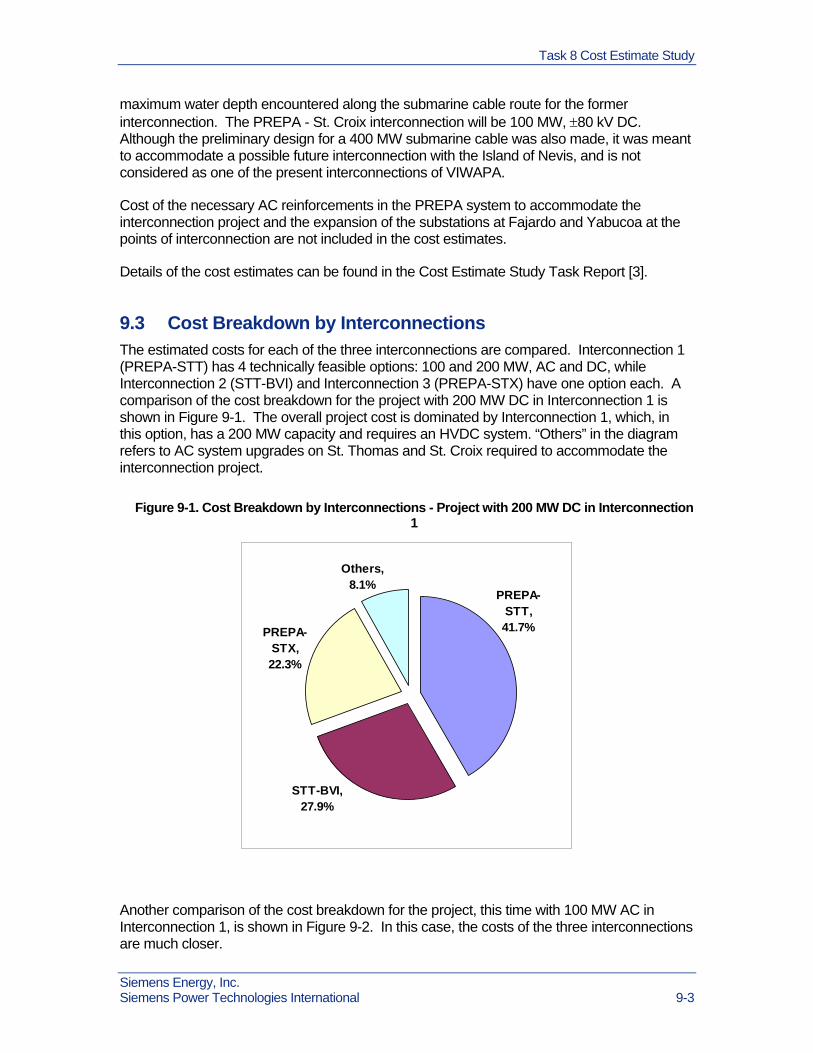
Task 8 Cost Estimate Study
maximum water depth encountered along the submarine cable route for the former interconnection. The PREPA - St. Croix interconnection will be 100 MW, 80 kV DC. Although the preliminary design for a 400 MW submarine cable was also made, it was meant to accommodate a possible future interconnection with the Island of Nevis, and is not considered as one of the present interconnections of VIWAPA.
Cost of the necessary AC reinforcements in the PREPA system to accommodate the interconnection project and the expansion of the substations at Fajardo and Yabucoa at the points of interconnection are not included in the cost estimates.
Details of the cost estimates can be found in the Cost Estimate Study Task Report [3].
9.3 Cost Breakdown by Interconnections The estimated costs for each of the three interconnections are compared. Interconnection 1 (PREPA-STT) has 4 technically feasible options: 100 and 200 MW, AC and DC, while Interconnection 2 (STT-BVI) and Interconnection 3 (PREPA-STX) have one option each. A comparison of the cost breakdown for the project with 200 MW DC in Interconnection 1 is shown in Figure 9-1. The overall project cost is dominated by Interconnection 1, which, in this option, has a 200 MW capacity and requires an HVDC system. “Others” in the diagram refers to AC system upgrades on St. Thomas and St. Croix required to accommodate the interconnection project.
Figure 9-1. Cost Breakdown by Interconnections - Project with 200 MW DC in Interconnection 1
PREPA-STX, 22.3%
STT-BVI, 27.9%
Others, 8.1%
PREPA-STT, 41.7%
Another comparison of the cost breakdown for the project, this time with 100 MW AC in Interconnection 1, is shown in Figure 9-2. In this case, the costs of the three interconnections are much closer.
Siemens Energy, Inc. Siemens Power Technologies International 9-3

Task 8 Cost Estimate Study
Figure 9-2. Cost Breakdown by Interconnections - Project with 100 MW AC in Interconnection 1
STT-BVI, 32.5%
PREPA-STX,
25.8%
Others, 9.5%
PREPA-STT,
32.3%
9.4 Cost Breakdown by Equipment A comparison of the total cost breakdown by major equipment for the interconnection project with the 200 MW DC link option in Interconnection 1 is shown in Figure 9-3. Of the project’s total estimated cost, about 75% is from the submarine cables, 14% from the HVDC converters and the remaining 11% from AC system equipment, including transformers, cable and transformer connections, circuit breakers, shunt capacitors and AC underground cables.
Siemens Energy, Inc. 9-4 Siemens Power Technologies International

Task 8 Cost Estimate Study
Figure 9-3. Cost Breakdown by Major Equipment - Project with 200 MW DC in Interconnection 1
HVDC, 14.1%
Others, 11.0%
Cables, 74.9%
Another comparison of the equipment cost for the whole project with the 100 MW AC link option in Interconnection 1 is shown in Figure 9-4. In this case, 83% of the estimated project cost is from submarine cables, 5% from HVDC converters and the remaining 12% from AC system equipment. A significant portion of the total project cost is from the submarine cables.
Figure 9-4. Cost Breakdown by Major Equipment - Project with 100 MW AC in Interconnection 1
Others, 12.2%
HVDC, 5.2%
Cables, 82.6%
Siemens Energy, Inc. Siemens Power Technologies International 9-5

Task 8 Cost Estimate Study
9.5 Economic Comparison The main difference among the options is the configuration of Interconnection 1, which can be AC or DC and 100 MW or 200 MW. A comparison of the overall costs is shown in Figure 9-5. The DC options are more costly mainly because of the VSC DC equipment. The difference is about 3% to 4% of the overall project cost The cost of shunt capacitors required in the PREPA system for the 200 MW AC option has not been included in these calculations, which may reduce the difference between the AC and DC options slightly. Increasing the rating of Interconnection 1 from 100 MW to 200 MW will cost approximately 12% to 13% more, either in the AC or DC option.
Figure 9-5. Comparison of Total Project Cost with various Options for Interconnection 1
Cost Comparison of Options
0.0%
20.0%
40.0%
60.0%
80.0%
100.0%
120.0%
200 MW DC 200 MW AC 100 MW DC 100 MW AC
Siemens Energy, Inc. 9-6 Siemens Power Technologies International
Section
10 Task 9 Benefits Study
10.1 Overview The objective of this task is to describe the potential benefits of the proposed interconnection project on the VIWAPA power system. These benefits can be characterized in three broad categories, namely, fossil fuel savings, improved reliability measured as a reduction in loss of load hours and less reliance on fossil fuel with a corresponding reduction in CO2
production.
10.2 Fossil Fuel Savings Generally, the largest expense category incurred by a utility in providing electric energy to its customers is fuel expense. At the present time, oil is the only fuel source used by VIWAPA. Although VIWAPA has indicated the potential for limited wind and solar on St. Thomas and St. Croix, it still needs to look elsewhere to meet the goal of 30% clean energy by 2030. To the extent that PREPA's system can absorb larger amounts of renewable resources than VIWAPA can, and the interconnection to PREPA comes to fruition, VIWAPA will have the opportunity to contract with renewable resources that connect to the PREPA system and expand on its ability to meet its clean energy goal reduce its air pollution, and also reduce its dependence on oil.
Production cost simulations were performed to assess the potential fuel cost savings in VIWAPA that may be gained by the interconnection with PREPA. Scenarios with and without the tie between St. Thomas/St John and PREPA and the tie between St. Croix and PREPA were analyzed. A 5 MW generic wind resource and a 5 MW generic solar resource were modeled on each main island. The system was dispatched for the time period 2015-2025. The hourly load net of renewable energy provides a measure of how much fixed energy can be imported from PREPA without causing significant dump energy problems. Dump is defined as the total generation exceeding load in any single hour with all operating units either set at their minimum loading or turned off.
For the alternate “PREPA Import” case, a desired import of 20 MW of 7x24 energy from PREPA was modeled. Preliminary results showed that there will be significant dump energy problem if St. Croix received more than 5 MW of fixed energy. Therefore, the 20 MW of import was split, with 5 MW going to St. Croix and the remaining 15 MW to St. Thomas. No consideration was given to the potential sale of power from VIWAPA to BVI in these calculations. A summary of the results is shown in Table 10-1.
Siemens Energy, Inc. Siemens Power Technologies International 10-1

Task 9 Benefits Study
10.3 Reliability Improvement The North American Reliability Council (NERC) defines a balancing area as an entity that integrates resource plans ahead of time, and maintains in real time the balance of electricity resources and electricity demand. Basically, each balancing authority is required to maintain system frequency by matching its generation to its demand, and as a balancing authority, VIWAPA would be required to perform this function whether it operates as an isolated system, or whether it is interconnected to PREPA. Since the islands of St. Thomas and St. Croix will not be directly connected, they will not be able to share system operating reserves.
The energy variable “Emergency” is an indication of how often the VIWAPA system incurs the loss of load under the study conditions. Another reliability indicator is the number of hours where there is a deficiency in the spinning reserve requirement. Both the variable “Emergency” and “Spinning Reserve Deficiency” decreases significantly between the base case and the PREPA tie case, indicating a more secure operating environment.
With the addition of interconnections between VIWAPA and PREPA and between VIWAPA and BVI, the adjacent balancing authorities could be a source of additional contingency reserves that would otherwise not be available to an isolated VIWAPA. The rules of engagement for the proposed transmission ties have yet to be defined, and as such the economic impact of potential reserve sharing cannot be properly evaluated. However, it should be noted that there is room for additional fuel cost savings if VIWAPA and its neighbors enter into reserve sharing agreements, such as those that exist between the North American reliability regions. An example of such an agreement would be one control area will activate spinning reserves for the loss of a large generator in an adjacent control area. This can reduce the amount of contingency reserves carried by each control area, and should improve reliability and provide fuel savings to both parties.
Should VIWAPA, PREPA, and BVI systems be interconnected, it is also recommended that the parties enter into emergency energy agreements, and coordinate their system restoration plans.
10.4 Carbon Dioxide Emission Reduction A major benefit from the installation of a tie between PREPA and VIWAPA is the reduction in fossil fuel and the resulting reduction in Carbon Dioxide Emissions. VIWAPA’s main source of power is from inefficient oil units, and therefore, the effective CO2 emission rate is relatively high. These units will not be called on to run as much if the PREPA tie is installed. This is expected to reduce CO2 production on the VIWAPA system by about 200,000 short tons a year. This represents an average production rate of 2,280 lbs/MWH, which is 36% higher than the average emission rate for oil generation in the US. The higher emission rate is due in part to the type of oil that is used, but is mostly due to operating the generating units at a less than optimum heat rate point because of the need to follow load and carry spinning reserve.
10.5 Results Summary Table 10-1 compares the volume and cost of energy to supply the VIWAPA electric system load between the business as usual case and the PREPA Import case. The expected purchase cost of the PREPA energy was not defined; however a range of prices was given.
Siemens Energy, Inc. 10-2 Siemens Power Technologies International

Task 9 Benefits Study
The results displayed in the table were calculated with an assumed purchase cost of $150/MWH. Alternate ranges of purchased power cost can be substituted for this assumption to find a break-even value consistent with fixed costs and financing assumptions.
Table 10-1. Potential Fuel Cost Benefits
2015 2016 2017 2018 2019 2020 2021 2022 2023 2024 2025
Fuel & O&M
Savings 36,107 36,657 42,097 40,028 44,568 43,484 41,891 47,655 47,952 48,269 48,333
PREPA
Import
(GWH)
175 176 175 175 175 176 175 175 175 176 175
Cost of
Import (k$) 26,276 26,345 26,276 26,302 26,276 26,345 26,276 26,276 26,276 26,370 26,276
Cost of
Emergency 3,281 1,917 6,308 2,677 6,859 4,471 2,879 6,021 6,749 4,593 7,779
Net Benefit 6,549 8,395 9,513 11,049 11,433 12,668 12,736 15,357 14,927 17,306 14,277
Table 10-2 shows the potential improvement in reliability in terms of a reduction in expected loss of load of about 330 hours per year.
Table 10-2. Potential Improvement in Reliability
2015 2016 2017 2018 2019 2020 2021 2022 2023 2024 2025
Reduction
in Loss of
Load
Hours
450 138 250 226 420 174 350 390 428 374 430
Table 10-3 shows the potential reduction in CO2 emission of about 202,000 short ton per year, on the average. These numbers do not include emissions in the PREPA system.
Table 10-3. Potential Environmental Impact Change
2015 2016 2017 2018 2019 2020 2021 2022 2023 2024 2025
CO2
Reduction
(1000
short ton)
194,820 198,550 199,848 205,176 202,631 204,113 199,480 208,654 200,979 202,746 202,018
These calculations illustrate that the addition of the tie to PREPA can provide benefits to VIWAPA in terms of savings in fuel cost, improvement in reliability and reduction in CO2 emission. The amount of benefits will depend on the level and price of energy being imported.
Siemens Energy, Inc. Siemens Power Technologies International 10-3

Task 9 Benefits Study
Siemens Energy, Inc. 10-4 Siemens Power Technologies International
This page intentionally left blank.

Section
11 Task 10 Final Report
11.1 Project Review Meeting #3 A meeting was held on June 17, 2011, in San Juan, Puerto Rico, during which the results of the Cost Estimate Study from Task 8 and the Benefits Study from Task 9 were reviewed.
A Project Review Meeting #3 was held in San Juan, Puerto Rico on June 17, 2011. The meeting was attended by representatives from VIWAPA, IAES, PREPA and DOE. Siemens PTI was represented by Baldwin Lam and Donna Anderson in person and Arthur Pinheiro and Lengcheng Huang via web meeting.
Lengcheng Huang gave an update on the Task 6 Power System Study results, which are contained in the revised Interim Report #2 [2] issued on June 10, 2011.
Arthur Pinheiro provided a summary of the Task 8 Cost Estimate Study, including the calculation assumptions and a comparison of the overall project equipment costs with various AC and DC transmission options for interconnection 1 between PREPA and St. Thomas. These results were detailed in the Task 8 Cost Estimate Study Draft Report [3], issued on June 10, 2011. It was noted that the costs of upgrades in the PREPA system that would be required to support the interconnections, including changes to the existing substations at the points of interconnection, were not included in the draft report, and would be provided later by PREPA.
Donna Anderson explained the assumptions used in the production cost calculations of the Task 9 Benefits Study, which were documented in a Task 9 Draft Report [4] issued on June 10, 2011. The calculations demonstrated potential savings in fuel cost in the VIWAPA system with a defined level of power import from PREPA. Some changes to the calculation assumptions were suggested. Siemens PTI would be updating the calculations and revising the Task 9 Report after the meeting.
It was decided that the Final Report be issued as soon as possible, documenting the work performed. Results from all the study tasks are summarized in this Final Report for the Interconnection Feasibility Study.
11.2 Recommendations Provisional designs have been developed for the submarine cable links of the three interconnections. As noted in the Submarine Cable Study Task, the proposed submarine cable route for Interconnection 3 between PREPA and St. Croix reaches a depth of 5,640 feet, which is slightly greater than the current world record for submarine power cables of
Siemens Energy, Inc. Siemens Power Technologies International 11-1

Task 10 Final Report
Siemens Energy, Inc. 11-2 Siemens Power Technologies International
5,300 feet held by the SAPEI Interconnection between Sardinia and Italian Mainland. It is recommended that the submarine cable design be subjected to laboratory testing and sea trial.
Interconnections 2A and 2B, because of the relatively moderate level of rated voltage and power capacity, will be AC transmission. Because of the longer distance (about 80 miles), only HVDC can be used for Interconnection 3.
Both AC and DC transmission options are technically feasible for Interconnection 1. The overall costs of the DC interconnection options are marginally higher than the corresponding AC options. The DC option does provide some technical advantages, such as lower transmission losses during high levels of power transfer, power flow and voltage control capability and lower short circuit current impact. When lifetime costs are taken into consideration, the DC interconnection is preferred. As noted in the Power System Study results, the HVDC system should be equipped with frequency control capability to maintain frequency in the VIWAPA system within acceptable levels during disturbances.
If the amount of power imported from PREPA on a regular basis is expected to be no more than 10 - 20 MW in the foreseeable future, then a transmission capacity of 100 MW for Interconnection 1 will be sufficient. Considering that the total demand on St. Thomas/St. John will reach about 110 MW by 2025 and the capacity of the cable link BVI is 40 MW, the larger 200 MW link will provide enough import capability to serve all the loads in St. Thomas/St. John and BVI during an emergency. The incremental cost of going from 100 MW to 200 MW in Interconnection 1 is about 12% to 13% of the overall project equipment cost. A choice between the 100 MW and 200 MW interconnection options will be a decision of VIWAPA.

Section
12 References
1) Interconnection Feasibility Study Interim Report #1, prepared for VIWAPA by Siemens PTI, Report #R03-11, originally issued on January 27, 2011, revised on May 30, 2011.
2) Interconnection Feasibility Study Interim Report #2, prepared for VIWAPA by Siemens PTI, Report #R56-11, originally issued on March 28, 2011, revised on June 7, 2011.
3) VIWAPA Interconnection Feasibility Study Cost Estimate Study Report, prepared for VIWAPA by Siemens PTI, Report #R57-11, originally issued on June 10, 2011, revised on August 1, 2011.
4) Siemens PTI, VIWAPA Interconnection Feasibility Study Benefits Study Report, prepared for VIWAPA by Siemens PTI, Report #R58-11, originally issued on June 10, 2011, revised on June 30, 2011.
Siemens Energy, Inc. Siemens Power Technologies International 12-1

References
Siemens Energy, Inc. 12-2 Siemens Power Technologies International
This page intentionally left blank.