interceptor optical network security system design guide · optical network security system design...
TRANSCRIPT
Interceptor™ Optical Network Security System
Design Guide
Chapter 6: Network Architectures!

Copyright © 2010 Network Integrity Systems, Inc.
All rights reserved.
The information in this document is subject to change without notice. The statements, configurations, technical data, and recommendations in this document are believed to be accurate and reliable, but are presented without express or implied warranty. Users must take full responsibility for their applications of any products specified in this document. The information in this document is proprietary to Network Integrity Systems, Inc. The software described in this document is furnished under a license agreement and may be used only in accordance with the terms of that license. The software license agreement is included in this document.
TrademarksNetwork Integrity Systems, Inc., the Network Integrity Systems, Inc. logo, and Interceptor are trademarks of Network Integrity Systems, Inc. Other brands and product names are trademarks or registered trademarks of their respective holders.
Statement of ConditionsIn the interest of improving internal design, operational function, and/or reliability, Network Integrity Systems, Inc. reserves the right to make changes to the products described in this document without notice. Network Integrity Systems, Inc. does not assume any liability that may occur due to the use or application of the product(s) or circuit layout(s) described herein.

INTERCEPTOR™ Design Guide
© 2010 Network Integrity Systems, Inc. – All Rights Reserved – Issue DG.9.2010 39
Chapter 6 | Network Architectures
This section of the Design Guide details the various network architectures that can be deployed using an INTERCEPTOR alarmed carrier PDS solution for inside and outside plant SIPRNet and JWICS networks. Selecting the correct network architecture can dramatically impact the longterm flexibility and scalability of a network, and it can also reduce both the cost and complexity of deployment. The goal of this section is to present several reference architectures for any of the following possible uses:
1. As a benchmark or a reference architecture for your own particular deployment;
2. As a repository of architectures from which to select in order to satisfy the requirements and scope of your deployment; or
3. As a source of ideas or technical approaches to assist in the development of your own custom architecture.
If your deployment scope is fairly large, you may find that you have to mix and match components from two or more architectures to develop an optimal fit for your deployment. Doing so, however, is often an indication that your deployment scope may still be too large, and that you could benefit from further segmenting your deployment scope or requirements. See Section on Deployment Scope, Chapter 5.
The network architectures are divided into two primary categories:
Outside Plant Architectures (OSP) – Between Buildings Inside Plant Architectures (ISP) – Inside of Buildings
The remainder of this section thoroughly reviews each type of architecture within each category and provides a summary of the key benefits and applications in order to help assist with selecting an appropriate architecture.
This section provides information pertinent to making the following key decisions:
Key Decision:
Selecting a network architecture or architectures that will support your deployment requirements and scope; and
Determining whether the selected architecture effectively balances deployment cost and complexity with future network growth and scalability.
INTERCEPTOR™ Design Guide
© 2010 Network Integrity Systems, Inc. – All Rights Reserved – Issue DG.9.2010 40
Chapter 6 | Network Architectures
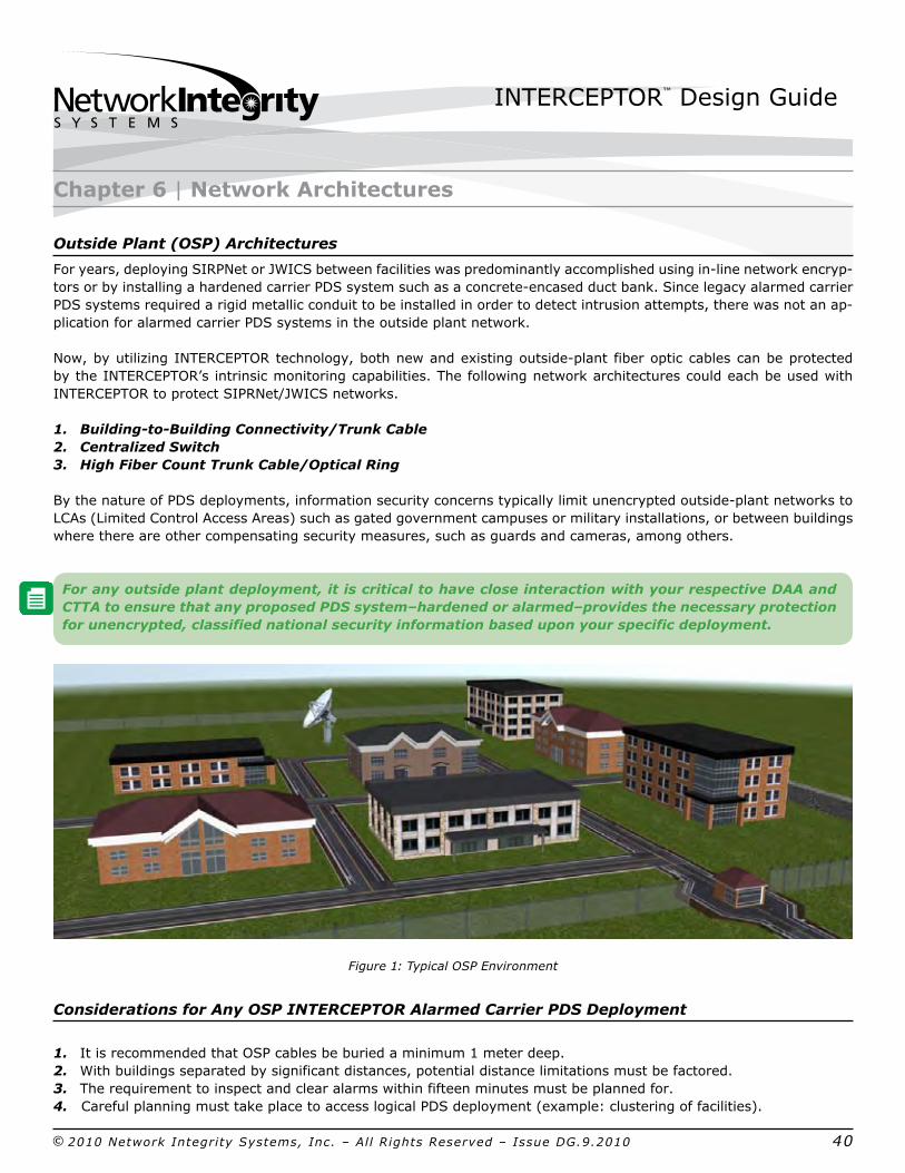
Outside Plant (OSP) Architectures
For years, deploying SIRPNet or JWICS between facilities was predominantly accomplished using inline network encryptors or by installing a hardened carrier PDS system such as a concreteencased duct bank. Since legacy alarmed carrier PDS systems required a rigid metallic conduit to be installed in order to detect intrusion attempts, there was not an application for alarmed carrier PDS systems in the outside plant network.
Now, by utilizing INTERCEPTOR technology, both new and existing outsideplant fiber optic cables can be protected by the INTERCEPTOR’s intrinsic monitoring capabilities. The following network architectures could each be used with INTERCEPTOR to protect SIPRNet/JWICS networks.
1. BuildingtoBuilding Connectivity/Trunk Cable2. Centralized Switch3. High Fiber Count Trunk Cable/Optical Ring
By the nature of PDS deployments, information security concerns typically limit unencrypted outsideplant networks to LCAs (Limited Control Access Areas) such as gated government campuses or military installations, or between buildings where there are other compensating security measures, such as guards and cameras, among others.
For any outside plant deployment, it is critical to have close interaction with your respective DAA and CTTA to ensure that any proposed PDS system–hardened or alarmed–provides the necessary protection for unencrypted, classified national security information based upon your specific deployment.
Figure 1: Typical OSP Environment
Considerations for Any OSP INTERCEPTOR Alarmed Carrier PDS Deployment
1. It is recommended that OSP cables be buried a minimum 1 meter deep.2. With buildings separated by significant distances, potential distance limitations must be factored.3. The requirement to inspect and clear alarms within fifteen minutes must be planned for.4. Careful planning must take place to access logical PDS deployment (example: clustering of facilities).

INTERCEPTOR™ Design Guide
© 2010 Network Integrity Systems, Inc. – All Rights Reserved – Issue DG.9.2010 41
This architecture is utilized to protect the buildingtobuilding trunk cable that is providing unencrypted SIPRNet or JWICS traffic.
Primary Applications
Many end user buildings receive SIPRNet or JWICS network traffic directly from the primary or secondary pointofpresence (POP) on a government campus or military installation.
For commercial buildings, several deployments also exist in which an agency or contractor has expanded from its current building to one or two other buildings in the same business park that also require secure network connectivity.
Figure 2: OSP BuildingtoBuilding Trunk Cables
Chapter 6 | Network Architectures–Outside Plant OSP1: BuildingtoBuilding Connectivity/Trunk Cable
Underground fiber optic cables
INTERCEPTOR™ Design Guide
© 2010 Network Integrity Systems, Inc. – All Rights Reserved – Issue DG.9.2010 42
Design Considerations
The nearterm and longterm secure connectivity requirements for the new buildings or facilities are the key considerations for implementing this type of deployment, as well as whether there will be a red/black equipment room in the new building or buildings or if the users or workcenters will be serviced off of the SIPRNet/JWICS switch in the current facility. If there will not be a red/black equipment room or information processing systems (IPS) in the new building or buildings, please refer to discussion of the Centralized Switch architecture.
For many outsideplant networks, the de facto standard is to use singlemode fiber; however, the cost of the LX electronics that are used to transmit optical signal on singlemode fiber is more than two or three times the cost of the SX electronics that are used on multimode fiber. Recent developments in 50µm laseroptimized multimode fiber now allows 10gbps transmission out to 500 meters. Therefore, it may be possible to leverage multimode fiber between buildings. For deployments where there will be a red/black equipment room or IPS vault, the fiber optic cables will serve as the trunk or uplink cable for every user in that facility. This can drastically increase the bandwidth demands over time on the SIPRNet/JWICS switch and the resulting trunk network or uplink back to the POP–especially considering that there will be close to 100% utilization of the network during crises or combat operations. As a result, it may be necessary to provide multiple optical circuits (pairs of fibers) that can be used to scale the bandwidth capacity of the network based on the type of network electronics used.
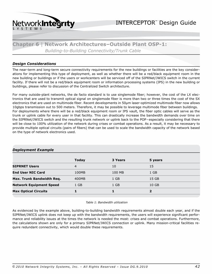
Deployment Example
Today 3 Years 5 years
SIPRNET Users 4 10 15
End User NIC Card 100MB 100 MB 1 GB Max. Trunk Bandwidth Req. 400MB 1 GB 15 GB
Network Equipment Speed 1 GB 1 GB 10 GB
Max Optical Circuits 1 1 2
Table 1: Bandwidth utilization
As evidenced by the example above, buildingtobuilding bandwidth requirements almost double each year, and if the SIPRNet/JWICS uplink does not keep up with the bandwidth requirements, the users will experience significant performance and reliability issues at the times the network is needed the most: crises and combat operations. Furthermore, the calculations shown are only for a primary SIPRNet/JWICS connection or uplink. Many missioncritical facilities require redundant connectivity, which would double these requirements.
Chapter 6 | Network Architectures–Outside Plant OSP1: BuildingtoBuilding Connectivity/Trunk Cable
INTERCEPTOR™ Design Guide
© 2010 Network Integrity Systems, Inc. – All Rights Reserved – Issue DG.9.2010 43
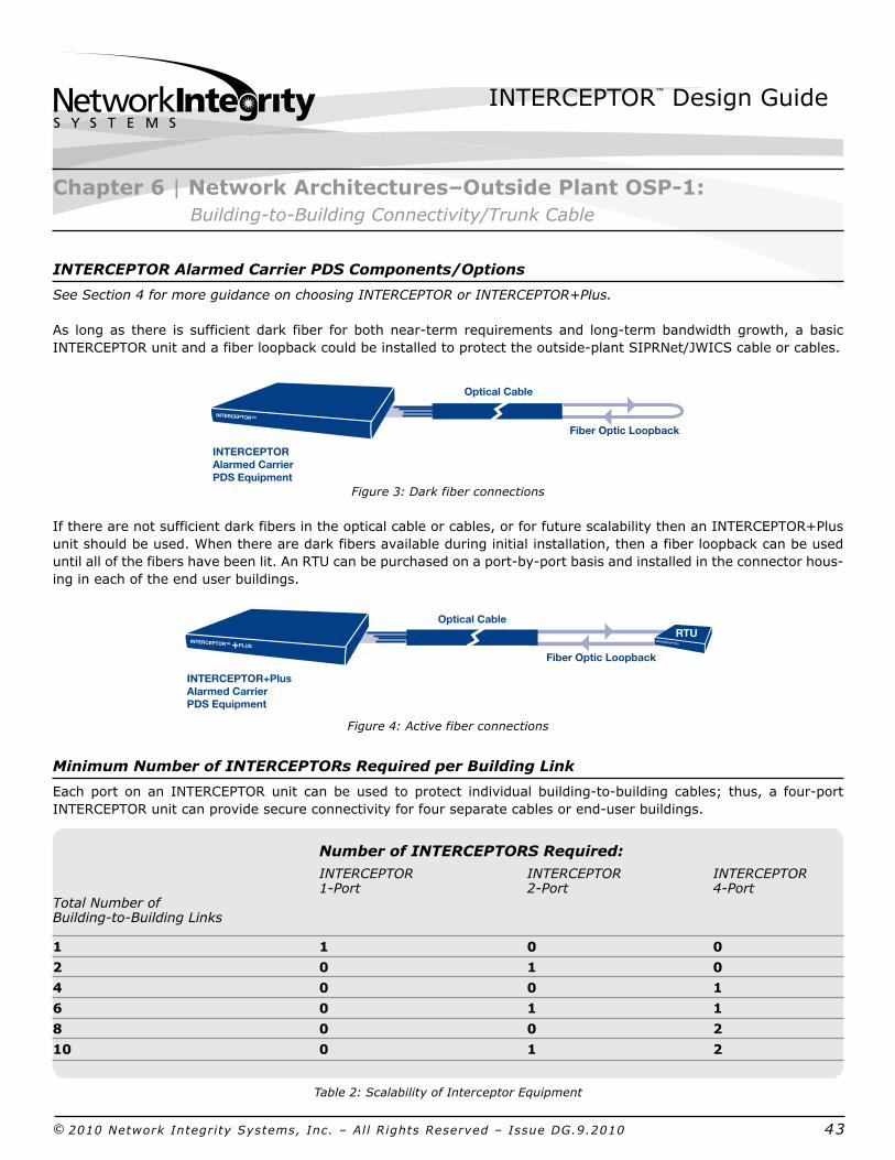
INTERCEPTOR Alarmed Carrier PDS Components/Options
See Section 4 for more guidance on choosing INTERCEPTOR or INTERCEPTOR+Plus.
As long as there is sufficient dark fiber for both nearterm requirements and longterm bandwidth growth, a basic INTERCEPTOR unit and a fiber loopback could be installed to protect the outsideplant SIPRNet/JWICS cable or cables.
Figure 3: Dark fiber connections
If there are not sufficient dark fibers in the optical cable or cables, or for future scalability then an INTERCEPTOR+Plus unit should be used. When there are dark fibers available during initial installation, then a fiber loopback can be used until all of the fibers have been lit. An RTU can be purchased on a portbyport basis and installed in the connector housing in each of the end user buildings.
Figure 4: Active fiber connections
Minimum Number of INTERCEPTORs Required per Building Link
Each port on an INTERCEPTOR unit can be used to protect individual buildingtobuilding cables; thus, a fourport INTERCEPTOR unit can provide secure connectivity for four separate cables or enduser buildings.
Number of INTERCEPTORS Required: INTERCEPTOR INTERCEPTOR INTERCEPTOR 1Port 2Port 4PortTotal Number ofBuildingtoBuilding Links
1 1 0 0
2 0 1 0
4 0 0 1
6 0 1 1
8 0 0 2
10 0 1 2
Table 2: Scalability of Interceptor Equipment
Fiber Optic Loopback
Optical Cable
INTERCEPTOR™
INTERCEPTOR Alarmed Carrier PDS Equipment
INTERCEPTOR+Plus Alarmed Carrier PDS Equipment
Fiber Optic Loopback
Optical Cable
INTERCEPTOR™ +PLUS INTERCEPTOR™RTU
RTU
Fiber Optic Loopback
Optical Cable
INTERCEPTOR™
INTERCEPTOR Alarmed Carrier PDS Equipment
INTERCEPTOR+Plus Alarmed Carrier PDS Equipment
Fiber Optic Loopback
Optical Cable
INTERCEPTOR™ +PLUS INTERCEPTOR™RTU
RTU
Chapter 6 | Network Architectures–Outside Plant OSP1: BuildingtoBuilding Connectivity/Trunk Cable
INTERCEPTOR™ Design Guide
© 2010 Network Integrity Systems, Inc. – All Rights Reserved – Issue DG.9.2010 44
Chapter 6 | Network Architectures–Outside Plant OSP1: BuildingtoBuilding Connectivity/Trunk Cable
Building BBuilding A
Patch Panel
Manhole
Building A
Manhole
Patch Panel
INTERCEPTOR
INTERCEPTOR™
Outdoor CableIndoor Cable Outdoor CableOutdoor CableSplice Case Splice Case
Cable 1Cable 1
Cable 2
Cable 3
Cable 4
Optical Cables
Building B
Patch Panel
INTERCEPTOR™
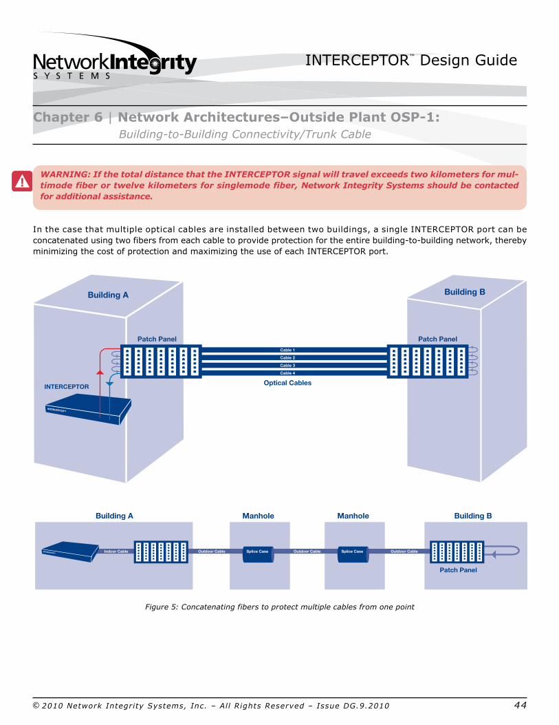
WARNING: If the total distance that the INTERCEPTOR signal will travel exceeds two kilometers for multimode fiber or twelve kilometers for singlemode fiber, Network Integrity Systems should be contacted for additional assistance.
In the case that multiple optical cables are installed between two buildings, a single INTERCEPTOR port can be concatenated using two fibers from each cable to provide protection for the entire buildingtobuilding network, thereby minimizing the cost of protection and maximizing the use of each INTERCEPTOR port.
Figure 5: Concatenating fibers to protect multiple cables from one point
INTERCEPTOR™ Design Guide
© 2010 Network Integrity Systems, Inc. – All Rights Reserved – Issue DG.9.2010 45
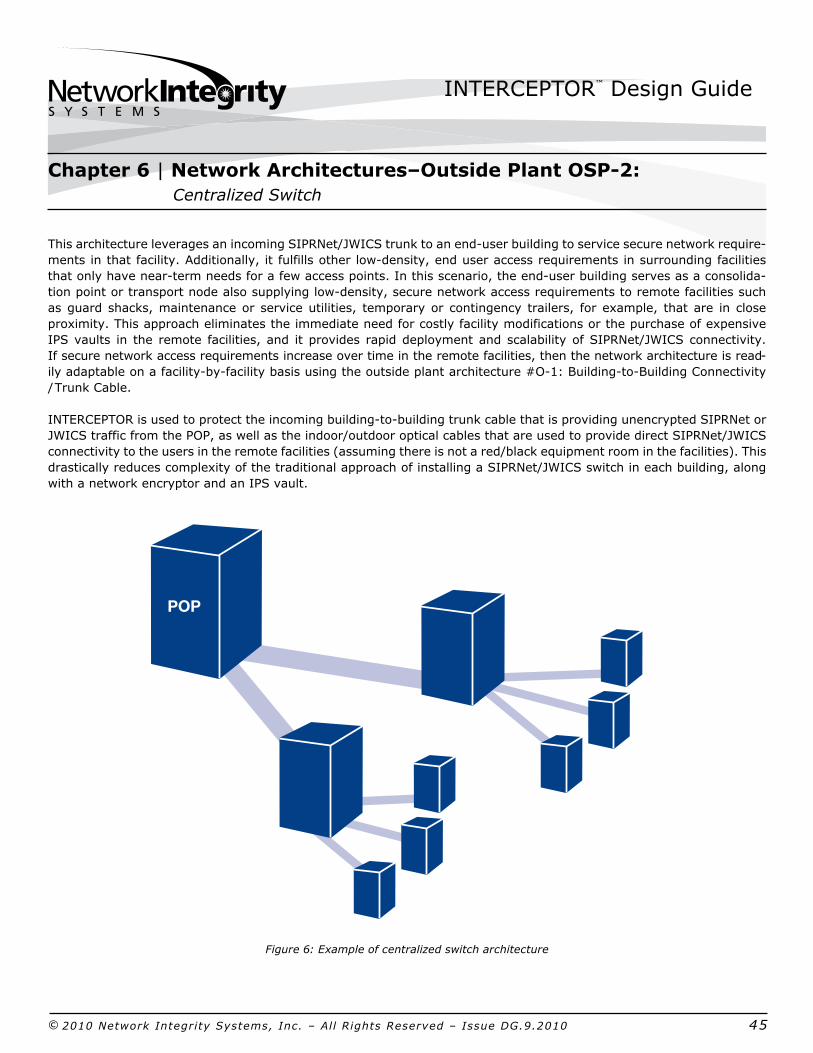
This architecture leverages an incoming SIPRNet/JWICS trunk to an enduser building to service secure network requirements in that facility. Additionally, it fulfills other lowdensity, end user access requirements in surrounding facilities that only have nearterm needs for a few access points. In this scenario, the enduser building serves as a consolidation point or transport node also supplying lowdensity, secure network access requirements to remote facilities such as guard shacks, maintenance or service utilities, temporary or contingency trailers, for example, that are in close proximity. This approach eliminates the immediate need for costly facility modifications or the purchase of expensive IPS vaults in the remote facilities, and it provides rapid deployment and scalability of SIPRNet/JWICS connectivity. If secure network access requirements increase over time in the remote facilities, then the network architecture is readily adaptable on a facilitybyfacility basis using the outside plant architecture #O1: BuildingtoBuilding Connectivity / Trunk Cable.
INTERCEPTOR is used to protect the incoming buildingtobuilding trunk cable that is providing unencrypted SIPRNet or JWICS traffic from the POP, as well as the indoor/outdoor optical cables that are used to provide direct SIPRNet/JWICS connectivity to the users in the remote facilities (assuming there is not a red/black equipment room in the facilities). This drastically reduces complexity of the traditional approach of installing a SIPRNet/JWICS switch in each building, along with a network encryptor and an IPS vault.
Figure 6: Example of centralized switch architecture
Chapter 6 | Network Architectures–Outside Plant OSP2: Centralized Switch
POP

INTERCEPTOR™ Design Guide
© 2010 Network Integrity Systems, Inc. – All Rights Reserved – Issue DG.9.2010 46
Primary Applications
In many cases, secure network access requirements are concentrated on missioncritical or combatsupport facilities where there is a medium to highdensity requirement for SIPRNet/JWICS access. Often, there are also requirements to provide SIPR/JWICS access to senior decision makers, support personnel, or communications room users, access to buildings that are in close proximity to the primary, missioncritical or combatsupport facility.
Some organizations cannot justify the high cost of a network encryptor and an IPS vault. As a result, these users are typically forced to access SIPRNet/JWICS in other facilities, which greatly increases the latency and complexity of communication and collaboration.
Design Considerations
Some important considerations for this type of deployment are as follows:
1. the number of buildings requiring SIPRNet/JWICS access that are in close proximity to the primary facility where the SIPRNet/JWICS switch and uplink is located; 2. the number of users requiring the secure network access in each of those buildings; 3. the distance of the buildings from the primary facility; and 4. the distance of the users requiring access from the indoor/outdoor demarcation point in each of the buildings.
For the cable that runs between the primary facility and the surrounding buildings, using armored, plenumrated, indoor/outdoor cable is highly recommended. It can be deployed pointtopoint from the SIPRNet/JWICS switch in the primary facility directly to the end user locations in the surrounding facility. By doing so, there is no need to have a demarcation point that transitions between outsideplant and indoor cabling.
INTERCEPTOR can also make use of existing optical cables between the primary facility and the surrounding buildings if there are sufficient dark fibers and the ability to separate red/black traffic in the cable (e.g., a separate buffer tube or subunit in the cable). Interlocking armored cables can then be installed from each building’s black equipment room to the end user locations. Since there is no network equipment being installed, and the SIPRNet/JWICS traffic is being optically transmitted, the outdoor cables can simply be patched over to the new interlocking armored cables without the need for an IPS vault or added security. However, we recommend that the transmission point (ex: patch panel) be secured in a NSTISSI 7003 approved lock box. INTERCEPTOR will protect the entire optical path–from the existing outsideplant cables to the newly installed interlocking armored cable. Once the cables are installed at the end user locations, a hardened workstation lock box can be installed and secured by a GSA approved padlock to provide the necessary protection for the SIPRNet/JWICS access points and to ensure that end users are authenticated by knowing the combination of the lock in order to get SIPRNet/JWICS access.
Chapter 6 | Network Architectures–Outside Plant OSP2: Centralized Switch
INTERCEPTOR™ Design Guide
© 2010 Network Integrity Systems, Inc. – All Rights Reserved – Issue DG.9.2010 47
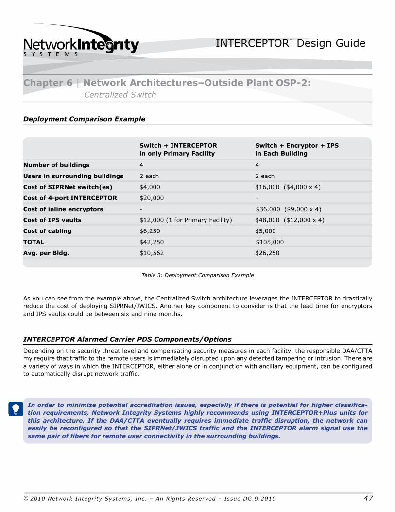
Deployment Comparison Example
Switch + INTERCEPTOR Switch + Encryptor + IPS
in only Primary Facility in Each Building
Number of buildings 4 4
Users in surrounding buildings 2 each 2 each
Cost of SIPRNet switch(es) $4,000 $16,000 ($4,000 x 4)
Cost of 4port INTERCEPTOR $20,000
Cost of inline encryptors $36,000 ($9,000 x 4)
Cost of IPS vaults $12,000 (1 for Primary Facility) $48,000 ($12,000 x 4)
Cost of cabling $6,250 $5,000
TOTAL $42,250 $105,000
Avg. per Bldg. $10,562 $26,250
Table 3: Deployment Comparison Example
As you can see from the example above, the Centralized Switch architecture leverages the INTERCEPTOR to drastically reduce the cost of deploying SIPRNet/JWICS. Another key component to consider is that the lead time for encryptors and IPS vaults could be between six and nine months.
INTERCEPTOR Alarmed Carrier PDS Components/Options
Depending on the security threat level and compensating security measures in each facility, the responsible DAA/CTTA my require that traffic to the remote users is immediately disrupted upon any detected tampering or intrusion. There are a variety of ways in which the INTERCEPTOR, either alone or in conjunction with ancillary equipment, can be configured to automatically disrupt network traffic.
In order to minimize potential accreditation issues, especially if there is potential for higher classification requirements, Network Integrity Systems highly recommends using INTERCEPTOR+Plus units for this architecture. If the DAA/CTTA eventually requires immediate traffic disruption, the network can easily be reconfigured so that the SIPRNet/JWICS traffic and the INTERCEPTOR alarm signal use the same pair of fibers for remote user connectivity in the surrounding buildings.
Chapter 6 | Network Architectures–Outside Plant OSP2: Centralized Switch

INTERCEPTOR™ Design Guide
© 2010 Network Integrity Systems, Inc. – All Rights Reserved – Issue DG.9.2010 48
INTERCEPTOR
INTERCEPTOR™
Lock Box
Lock Box
Lock Box
INTERCEPTOR Alarmed Carrier PDS Components/Options
Figure 7: Centralized switch network Design
As long as there are sufficient dark fibers that can be dedicated to INTERCEPTOR monitoring in any and all of the optical cables between the SIPERNET/JWICS switch in the primary facility and the end user locations in the surrounding buildings, a fiber loopback can be installed in the workstation lock box to minimize initial deployment costs.
Photo 1: Loopback in Workstation Box
The fiber loopback can be replaced by an RTU if and when the ability to immediately terminate traffic to the remote users upon INTERCEPTOR alarm becomes required, or if the dark fibers need to be lit up for other secure network requirements, such as adding ports, for example.
Scalability of INTERCEPTOR Equipment
At least one INTERCEPTOR port per every incoming SIPRNet/JWICS cable will be required to protect the uplink. Additionally, since each remote user or end user location in the surrounding facilities has a dedicated cable drop installed, there must be one INTERCEPTOR port for every remote end user being serviced from the centralized switch in the primary facility.
Additional INTERCEPTOR ports may be required in order to protect the distribution of the SIPRNet/JWICS traffic to the end users in the primary facility.
Chapter 6 | Network Architectures–Outside Plant OSP2: Centralized Switch

INTERCEPTOR™ Design Guide
© 2010 Network Integrity Systems, Inc. – All Rights Reserved – Issue DG.9.2010 49
This architecture protects a highfiber count optical trunk cable or ring that is used to provide SIPRNet/JWICS connectivity from a single POP to multiple buildings—i.e., point to multipoint. The key difference between this architecture and #O1 (BuildingtoBuilding Connectivity /Trunk Cable) is that this architecture employs only one trunk cable to connect all of the buildings, via lateral cables and splice cases, as compared to the O1 architecture’s which have a dedicated cable running to each building. This architecture also supports any deployment involving an optical ring or bus type of topology.
Figure 8: High fiber count trunk cable/optical ring network design
Primary Applications
The traditional telecommunications networking approach for outside plant fiber optic networks is to use a single, highfiber count trunk cable (e.g., 72288F) that “passes“ each building requiring access. Each building then has a lowfiber count (e.g., 1224F) drop cable installed that is fusion spliced or patched to a subset of the fibers in the trunk cables, usually in twelvefiber increments; for example,. one or two of the buffer tubes or subunits inside the trunk cable.
Figure 9: Detail of cable splicing and drops to buildings
Protecting not only the entire trunk cable but also each individual building drop cable so that the SIPRNet/JWICS traffic is being protected all the way from the POP to the end user building is the main challenge associated with using this architecture.
Chapter 6 | Network Architectures–Outside Plant OSP3: High Fiber Count Trunk Cable/Optical Ring
POP
48-Fiber Cable
12-Fiber Drop
Splice Point Splice Point Splice Point Splice Point
12-Fiber Drop 12-Fiber Drop 12-Fiber Drop
High-Fiber Count Fiber Optic Cable
Buffer Tubes
12-Fiber Drop Cable
Building A Building B Building C Building D
Splice Point(in splice closure)
Dark Fibers past the Splice Points...

INTERCEPTOR™ Design Guide
© 2010 Network Integrity Systems, Inc. – All Rights Reserved – Issue DG.9.2010 50
Design Considerations
Key considerations for deployment in this architecture are the length of the optical trunk cable and the clustering, or close proximity, of end user buildings to one another. Typically, enduser buildings can easily be clustered together in groups of two or four buildings.
Rather than developing or altering the trunk / drop cable fusion splice plan to factor in dedicated fibers for alarmed carrier PDS, it is simpler to treat each twelve or twentyfourfiber building connection as a pointtopoint network, and simply cross or interconnect the necessary fibers together in the various equipment or telecommunication rooms for trunk cable (usually at the POP) and the drop cable or cables for the enduser buildings. Using this approach, an INTERCEPTOR can be dedicated to each building–pointtopoint protection–or a single INTERCEPTOR port can be shared by all of the buildings in a cluster as long as they are in close proximity to one another.
When conducting fiber planning, it is best to define the requirements at the end points of the network (e.g., the end user buildings) and work backwards. In order to calculate how many fibers to deploy in the building drop cables, you first must determine how many fibers you will need for SIPRNet traffic at each building–both nearterm and longterm. Remember that it is standard practice for fibers to be spliced or connected from the trunk cable to the building drop cables or laterals in counts of six or twelve fibers. Once you identify how many fibers are needed for SIPRNet requirements, and factor in growth at each building, add two dark fibers to that calculation for INTERCEPTOR monitoring. In order to plan for spares and future growth, it is prudent to add 20% to 25% more fibers, and then round this number up to the nearest multiple of 12. This results in a determination of the fiber count needed for your building drop cables.
To calculate the fiber count required for the trunk cable, multiply the drop cable fiber count by the number of buildings that will be passed by the highfiber count trunk cable and add–between 24 and 48 spare fibers. This way, you not only have enough fibers to meet current requirements, you also have enough for any future requirements or to counteract the possibility that some buffer tubes or subunits become damaged over time. Rounding this number up to the next multiple of 72 produces the number of fibers needed in the trunk cable.
Keep in mind that the most expensive part of any deployment is the labor and installation, especially for outside plant deployments. Planning for future growth through dark fibers or spare ducts is absolutely critical.
Chapter 6 | Network Architectures–Outside Plant OSP3: High Fiber Count Trunk Cable/Optical Ring

INTERCEPTOR™ Design Guide
© 2010 Network Integrity Systems, Inc. – All Rights Reserved – Issue DG.9.2010 51
Deployment Example
A highfiber count trunk cable is to be installed on a military installation to serve as the primary SIPRNet distribution for several missioncritical or combatsupport facilities.
Today 3 Years 5 years
Total Buildings Passed by Trunk Cable 10 10 12 (2 new constr ???)
Buildings Requiring SIPRNet Connectivity 4 8 10 Fibers Required per Building 4F 4F 8Ffor SIPRNet Network
Fibers Required per Building 2F 2F 2Ffor INTERCEPTOR
Drop Cable Fiber Count 12F 12F 12F (4F+2F+20%*)<12F (4F+2F+20%*)<12F (8F+2F+20%*)<24F
Trunk Cable Fiber Count Required 144F 144F 216F (120F+24F)=144F (120F+24F)=144F (144F+48F)<216F
*Standard optical network design calls for 20% spare optical fibers.
Table 4: Deployment Example
Based on the calculations above, the military installation should install a trunk cable with at least 216 fibers, and use building drop cables with at least twelve fibers each.
INTERCEPTOR Alarmed Carrier PDS Components/Options
Whenever INTERCEPTOR units are deployed as part of a optical trunk cable or ring, it is highly recommended that INTERCEPTOR+Plus units are used; thus, if one or two buildings need to light up all the fibers in the drop cable, you can simply install an RTU at one end instead of needing a new INTERCEPTOR unit.
Figure 10: High fiber count trunk cable optical ring network design
Chapter 6 | Network Architectures–Outside Plant OSP3: High Fiber Count Trunk Cable/Optical Ring
P1
P2
P3
P4
Splice Case
Splice Case
Splice Case
Splice Case
Building A Building B Building C Building D
Patch Panel with Loop Back
Patch Panel with Loop Back
Patch Panel with Loop Back
48 Fiber Trunk Cable
INTERCEPTOR+Plus Alarmed Carrier PDS Equipment
INTERCEPTOR™ +PLUS
RTUINTERCEPTOR™RTU
INTERCEPTOR™ Design Guide
© 2010 Network Integrity Systems, Inc. – All Rights Reserved – Issue DG.9.2010 52
INTERCEPTOR Alarmed Carrier PDS Components/Options
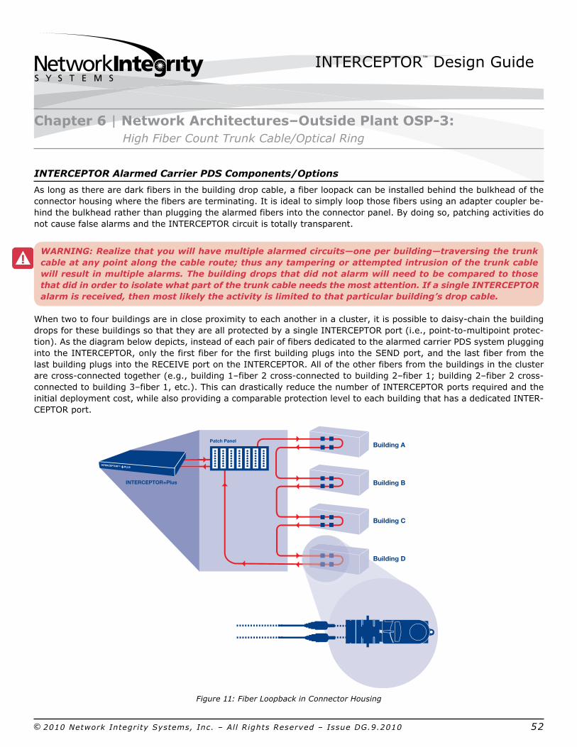
As long as there are dark fibers in the building drop cable, a fiber loopack can be installed behind the bulkhead of the connector housing where the fibers are terminating. It is ideal to simply loop those fibers using an adapter coupler behind the bulkhead rather than plugging the alarmed fibers into the connector panel. By doing so, patching activities do not cause false alarms and the INTERCEPTOR circuit is totally transparent.
WARNING: Realize that you will have multiple alarmed circuits—one per building—traversing the trunk cable at any point along the cable route; thus any tampering or attempted intrusion of the trunk cable will result in multiple alarms. The building drops that did not alarm will need to be compared to those that did in order to isolate what part of the trunk cable needs the most attention. If a single INTERCEPTOR alarm is received, then most likely the activity is limited to that particular building’s drop cable.
When two to four buildings are in close proximity to each another in a cluster, it is possible to daisychain the building drops for these buildings so that they are all protected by a single INTERCEPTOR port (i.e., pointtomultipoint protection). As the diagram below depicts, instead of each pair of fibers dedicated to the alarmed carrier PDS system plugging into the INTERCEPTOR, only the first fiber for the first building plugs into the SEND port, and the last fiber from the last building plugs into the RECEIVE port on the INTERCEPTOR. All of the other fibers from the buildings in the cluster are crossconnected together (e.g., building 1–fiber 2 crossconnected to building 2–fiber 1; building 2–fiber 2 crossconnected to building 3–fiber 1, etc.). This can drastically reduce the number of INTERCEPTOR ports required and the initial deployment cost, while also providing a comparable protection level to each building that has a dedicated INTERCEPTOR port.
Figure 11: Fiber Loopback in Connector Housing
Chapter 6 | Network Architectures–Outside Plant OSP3: High Fiber Count Trunk Cable/Optical Ring
INTERCEPTOR+Plus
Building A
Building B
Building C
Building D
Patch Panel
INTERCEPTOR™ +PLUS

INTERCEPTOR™ Design Guide
© 2010 Network Integrity Systems, Inc. – All Rights Reserved – Issue DG.9.2010 53
Scalability of INTERCEPTOR Equipment
As long as two fibers for each building are being monitored by an INTERCEPTOR, no additional INTERCEPTOR equipment or configuration is required, even if additional fibers to some of the buildings are lit up. Additional INTERCEPTOR ports are only necessary if additional buildings are constructed along the trunk cable, thus requiring the installation of a new drop cable, or if some of the buildings required additional drop cables to be installed in addition to the one already protected by the INTERCEPTOR. If a drop cable is damaged and a new drop cable is installed in its place, then the existing INTERCEPTOR equipment can simply be reconfigured to ensure that the new cable is being protected, and the old cable can be abandoned as long as no SIPRNet/JWICS traffic is still being transmitted over it.
In the rare case that multiple drop cables are installed to a building, a single INTERCEPTOR port can be concatenated using one fiber from each cable to provide protection for both drop cables, which minimizes the cost of protection and maximizes the use of each INTERCEPTOR port.
WARNING: It is important to make sure that the total distance that the INTERCEPTOR signal will travel will not exceed two kilometers for multimode fiber or twelve kilometers for singlemode fiber. INTERCEPTOR can support much longer distances, but doing so requires careful application engineering. Please contact Network Integrity Systems for additional assistance.
Chapter 6 | Network Architectures–Outside Plant OSP3: High Fiber Count Trunk Cable/Optical Ring

INTERCEPTOR™ Design Guide
© 2010 Network Integrity Systems, Inc. – All Rights Reserved – Issue DG.9.2010 54
Five years ago, SIPRNet or JWICS deployments inside of a facility were extremely rare. In fact, most deployments were either to command and control centers, intelligence areas, or senior leadership offices and quarters. With the impact of netcentricity and the increased utilization of the Global Information Grid for enhanced communication and collaboration, there has been an explosion of SIPRNet and other SECRET and above level network deployments across both the DOD and civilian agencies.
For years, the traditional method of deploying SIPRNet for inbuilding requirements was either by installing a hardened carrier PDS system, such as a rigid metallic conduit along the wall, for example, or deploying an IPS vault with an inline network encryptor and a dedicated laptop for a single seat solution. Both of these approaches required dedicated, homerun cables to be installed directly from the equipment room of the facility to the workstation or end user area, and did not adequately support the flexibility and scalability required by current secure network deployments. With the high cost of network encryptors and the operational burden of Public Key Infrastructure (PKI), many government agencies and military installations have already transitioned to the use of a PDS system inside of facilities to distribute unencrypted SECRET and above information. Now, with the explosion in the number of users in each facility, many agencies and installations are looking for new options to further reduce the cost and complexities of secure network deployments and provide a more flexible and scalable solution.
INTERCEPTOR’s intrinsic monitoring technology is designed to protect fiber optic cables within buildings. In fact, many CONUS and OCONUS deployments can even leverage interlocking armor cable in place of the EMT or rigid metallic conduit that was once required by older alarmed carrier solutions (see page 29). The following architectures could be used with INTERCEPTOR to protect inside SIPRNet/JWICS networks.
For any deployment leveraging the armored cable option, it is critical to have close interaction with your respective CTTA. Every PDS system–hardened or alarmed–must be evaluated on its own merits and characteristics to ensure that the secure network receives adequate protection against both internal and external threats.
Figure 12: Typical inside plant environment
Chapter 6 | Network Architectures–Overview of Network Architectures for InBuilding SIPRNET/JWICS Deployments
INTERCEPTOR™ Design Guide
© 2010 Network Integrity Systems, Inc. – All Rights Reserved – Issue DG.9.2010 55
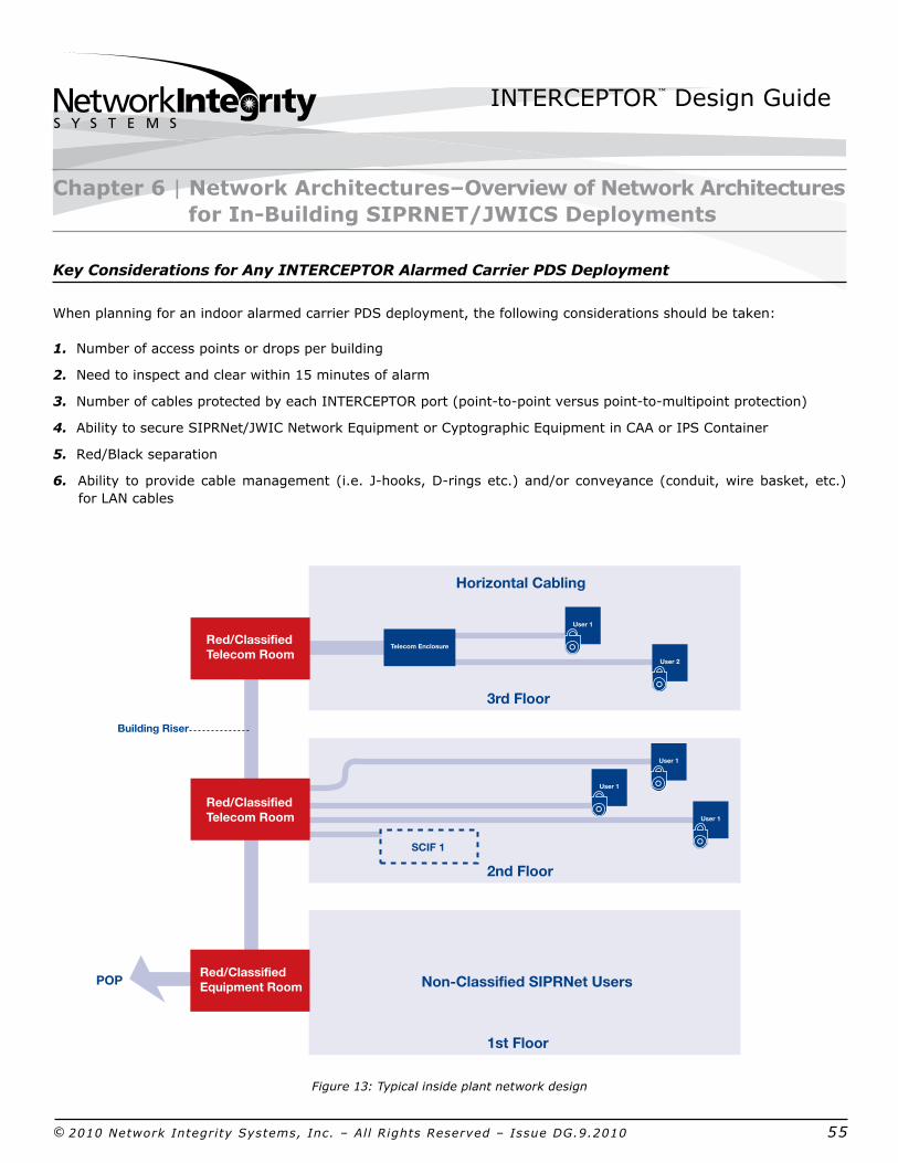
Key Considerations for Any INTERCEPTOR Alarmed Carrier PDS Deployment
When planning for an indoor alarmed carrier PDS deployment, the following considerations should be taken:
1. Number of access points or drops per building
2. Need to inspect and clear within 15 minutes of alarm
3. Number of cables protected by each INTERCEPTOR port (pointtopoint versus pointtomultipoint protection)
4. Ability to secure SIPRNet/JWIC Network Equipment or Cyptographic Equipment in CAA or IPS Container
5. Red/Black separation
6. Ability to provide cable management (i.e. Jhooks, Drings etc.) and/or conveyance (conduit, wire basket, etc.) for LAN cables
Figure 13: Typical inside plant network design
Chapter 6 | Network Architectures–Overview of Network Architectures for InBuilding SIPRNET/JWICS Deployments
1st Floor
2nd Floor
User 2
POP
Red/ClassifiedTelecom Room
Telecom Enclosure
SCIF 1
Horizontal Cabling
Non-Classified SIPRNet Users
3rd Floor
Building Riser
Red/ClassifiedEquipment Room
User 1
User 1
User 1
User 1
Red/ClassifiedTelecom Room
INTERCEPTOR™ Design Guide
© 2010 Network Integrity Systems, Inc. – All Rights Reserved – Issue DG.9.2010 56
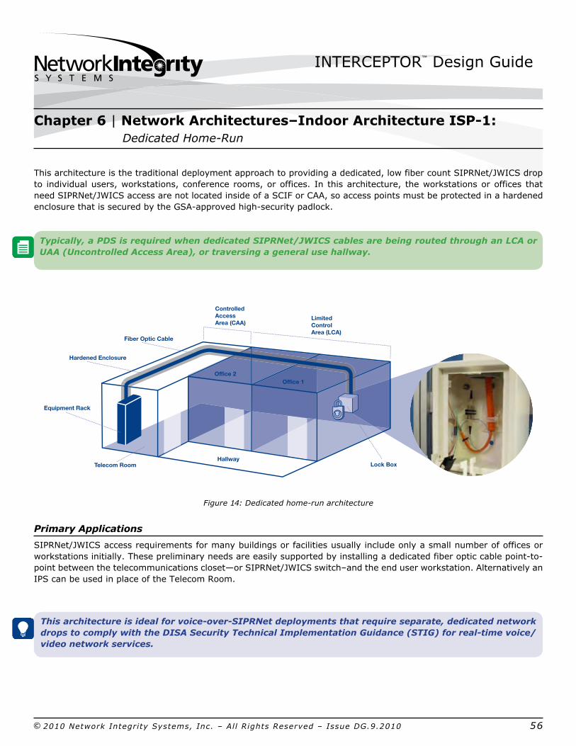
This architecture is the traditional deployment approach to providing a dedicated, low fiber count SIPRNet/JWICS drop to individual users, workstations, conference rooms, or offices. In this architecture, the workstations or offices that need SIPRNet/JWICS access are not located inside of a SCIF or CAA, so access points must be protected in a hardened enclosure that is secured by the GSAapproved highsecurity padlock.
Typically, a PDS is required when dedicated SIPRNet/JWICS cables are being routed through an LCA or UAA (Uncontrolled Access Area), or traversing a general use hallway.
Figure 14: Dedicated homerun architecture
Primary Applications
SIPRNet/JWICS access requirements for many buildings or facilities usually include only a small number of offices or workstations initially. These preliminary needs are easily supported by installing a dedicated fiber optic cable pointtopoint between the telecommunications closet—or SIPRNet/JWICS switch–and the end user workstation. Alternatively an IPS can be used in place of the Telecom Room.
This architecture is ideal for voiceoverSIPRNet deployments that require separate, dedicated network drops to comply with the DISA Security Technical Implementation Guidance (STIG) for realtime voice/video network services.
Chapter 6 | Network Architectures–Indoor Architecture ISP1: Dedicated HomeRun
Office 1Office 2
HallwayTelecom Room
Equipment Rack
Hardened Enclosure
Fiber Optic Cable
Controlled Access Area (CAA)
Limited Control Area (LCA)
Photo of Lock Box with Splice Closure (inside?)
Lock Box
Product Photography is only about 900k, and image reproduces blurry....reshoot photo?
INTERCEPTOR™ Design Guide
© 2010 Network Integrity Systems, Inc. – All Rights Reserved – Issue DG.9.2010 57
Design Considerations
When designing a network using this Dedicated HomeRun architecture, there are three primary design considerations:
1. Protecting the SIPRNet/JWICS network equipment
2. Determining the fiber count of the workstation cables
3. Protecting the SIPRNet/JWICS access points
Consideration 1: Protecting the SIPRNET/JWICS Network Equipment
Many facilities do not have a red/black equipment room or even any areas that meet CAA criteria. For these scenarios, the use of an IPS container is highly recommended as a quick and costeffective way to provide SIPRNet/JWICS network access without having to undergo costly and intrusive facility modifications. For those facilities that do have existing red/black equipment rooms or CAAs, the SIPRNet/JWICS and INTERCEPTOR equipment should be installed in them.
Consideration 2: Determining the Fiber Count of the Workstation Cables
In addition to the number of fibers required for data transmission, two dark fibers in each workstation cable should be allocated and dedicated to the INTERCEPTOR for alarmed monitoring. This can be accomplished be either (1) adding two additional fibers to the number of lit and spare fibers, thus allowing you to use a regular INTERCEPTOR unit and simply loop the fibers inside of the workstation lockbox, or (2) using some of the spare fibers for INTERCEPTOR monitoring in order to reduce the fiber count of the workstation cables and the initial deployment cost, but at the same time accepting the risk that you may need to purchase RTUs for the workstation enclosures if you ever need to light up the spare fibers initially used by INTERCEPTOR. (The latter approach also requires an INTERCEPTOR+Plus unit for future scalability).
Adding a few extra fibers to each workstation cable adds only pennies per foot to the cost of material, and it also reduces deployment costs by enabling the use of regular INTERCEPTOR units.
Keep in mind that the most expensive part of any network deployment is the labor and installation. Planning for future growth through dark or spare fibers is absolutely critical.
Consideration 3: Protecting the SIPRNET/JWICS Access Points
The homerun workstation cables must be terminated in a hardened enclosure according to NSTISSI 7003 requirements. An important decision is whether to have one enclosure per workstation, or alternatively to have multiple workstations using a single hardened enclosure, such as in the context of adjacent cubicles or open area workcenters, for example.
Chapter 6 | Network Architectures–Indoor Architecture ISP1: Dedicated HomeRun

INTERCEPTOR™ Design Guide
© 2010 Network Integrity Systems, Inc. – All Rights Reserved – Issue DG.9.2010 58
Deployment Cost Analysis Example
A military unit needs to deploy SIPRNet to four offices in its operations facility, each with 3 SIPR workstations. The offices are not inside of a SCIF or CAA. Each office needs a minimum of four fibers for SIPRNet connections, and the military unit expects that other SECRET level networks (e.g., CITRIX, COALITION, etc) may be required in the future. Further, it would like to have 50% spare fibers for future requirements.
Based on the requirement of four fibers for SIPR and another four fibers for future growth, the workstation cables will either be an 8fiber or 12fiber cable. The table below highlights the differences between adding dedicated fibers as opposed to using spare fibers
Adding Dedicated Fibers Using Spare Fibers
Interlocking Armored Cable Fiber Count 12 8
Interlocking Armored Cable Cost Per Foot $1.30 $1.20 Total Cost for Workstation Cables $2340 $2160(150 ft. per Drop)
4 Port INTERCEPTOR Unit $19,000 X
4 Port INTERCEPTOR+Plus Unit X $27,000
May Require Future Purchases or RTUs X $30,000
INTERCEPTOR Equipment Cost $21,340 $59,160
Total Installed cost for 12 Workstations $1,800/drop $2,400/drop today (without RTUs)
Total Installed cost for 12 Workstations when RTUs are required: $4,900/drop
Table 5: Deployment cost analysis example
INTERCEPTOR Alarmed Carrier PDS Components/Options
As evidenced by the table above, even after adding the extra fibers to the workstation cables, dedicating fibers for the INTERCEPTOR system remains the cheapest solution and negates the need for the future potential purchase of RTUs for the workstation enclosures. As long as it is certain that two fibers will always be dedicated to INTERCEPTOR monitoring, standard INTERCEPTOR units can be deployed. However, if there is any uncertainty or concern that those fibers may be needed in the future, then investing in an INTERCEPTOR+Plus unit futureproofs your network and negates the need to buy a new INTERCEPTOR+Plus unit to replace your originally purchased unit. Therefore, if all of the fibers in the drop cable feeding a workstation need to be activated an RTU can be installed at that time eliminating the need to replace the INTERCEPTOR with a new INTERCEPTOR+Plus.
Chapter 6 | Network Architectures–Indoor Architecture ISP1: Dedicated HomeRun

INTERCEPTOR™ Design Guide
© 2010 Network Integrity Systems, Inc. – All Rights Reserved – Issue DG.9.2010 59
INTERCEPTOR Alarmed Carrier PDS Components/Options
If there are dark fibers in the workstation drop cable, a fiber loopback can be installed behind the faceplate at the workstation. By doing so the SIPRNet/JWICS fibers terminate into the faceplate, but the alarmed fibers are looped behind the faceplate, thus making the INTERCEPTOR system completely transparent to the end users. By also leveraging the CTTA approval to use interlocking armored cable as part of an INTERCEPTOR system, the dedicated workstation drops can be run above the ceiling or below a raised floor. The armored cables can be deployed from the telecommunications closet by using jhooks or wire basket for cable management and support.
Since the workstations are located in an LCA, the INTERCEPTOR alarmed PDS cables must be terminated into a hardened enclosure that meets NSTISSI 7003 requirements; therefore, a GSA approved padlock must secure the enclosure.
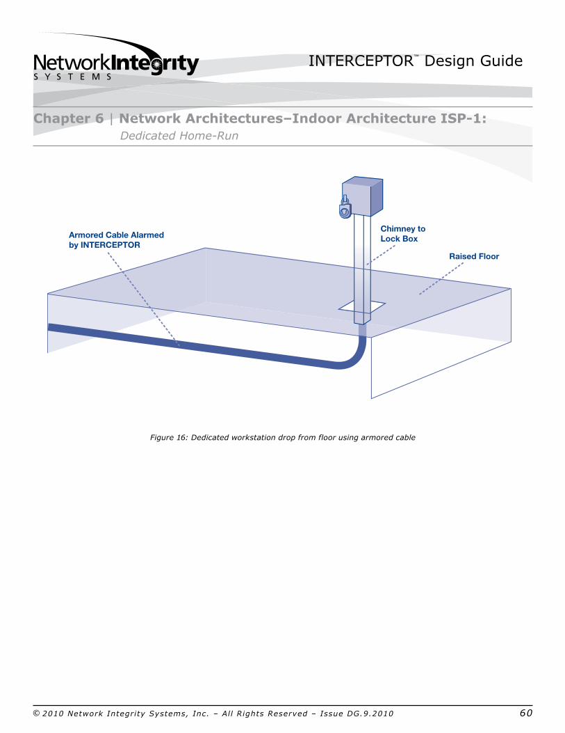
In order to streamline installation, you can make use of a prefabricated hardened workstation enclosure with a oneinch conduit chimney as depicted in the diagram below. This makes routing the armored cables from the ceiling or floor to the hardened workstation enclosure less difficult and drastically reduces the complexity of trying to fish the cables through walls or other obstacles, as well as adds to the aesthetics of the workstation.
Figure 15: Dedicated workstation drop from ceiling using armored cable
Chapter 6 | Network Architectures–Indoor Architecture ISP1: Dedicated HomeRun
Photo of Lock Box with Splice Closure (inside?)
Photo of Lock Box with Splice Closure (inside?)
False/Drop Ceiling
Armored Cable Alarmed by INTERCEPTOR Chimney to
Lock Box
INTERCEPTOR™ Design Guide
© 2010 Network Integrity Systems, Inc. – All Rights Reserved – Issue DG.9.2010 60
Figure 16: Dedicated workstation drop from floor using armored cable
Chapter 6 | Network Architectures–Indoor Architecture ISP1: Dedicated HomeRun
Photo of Lock Box with Splice Closure (inside?)
Raised Floor
Armored Cable Alarmed by INTERCEPTOR
Lori to add cables showing in wire baskets:Optional Deployment shwing cable tray conveyance when armored cable is used outside of conduit....
Chimney to Lock Box

INTERCEPTOR™ Design Guide
© 2010 Network Integrity Systems, Inc. – All Rights Reserved – Issue DG.9.2010 61
Figure 17: Dedicated homerun architecture design example
Scalability of INTERCEPTOR Equipment
In this architecture, one INTERCEPTOR port is used to protect one workstation cable. Thus, as new workstation requirements emerge, an equal number of INTERCEPTOR ports will need to be added to protect those new cables. (A 4port INTERCEPTOR unit will protect 4 workstation drops).
If INTERCEPTOR+Plus units were initially deployed, and you currently need to light up all of the fibers in your workstation cables, you can purchase RTUs on a workstationbyworkstation basis to eliminate the need to pull in higher fibercount cables.
Chapter 6 | Network Architectures–Indoor Architecture ISP1: Dedicated HomeRun
Office 2Office 1
Hallway
Dedicated Cable Run
Limited Access Area
SIPRNetTelecom Room
NIPRNet Telecom Room
Lock Box
INTERCEPTOR
ControlledAccess Area
INTERCEPTOR™ Design Guide
© 2010 Network Integrity Systems, Inc. – All Rights Reserved – Issue DG.9.2010 62
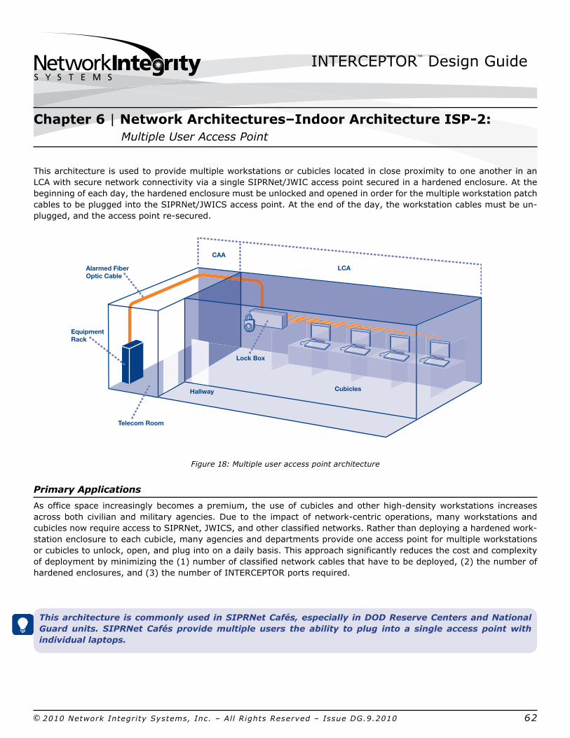
This architecture is used to provide multiple workstations or cubicles located in close proximity to one another in an LCA with secure network connectivity via a single SIPRNet/JWIC access point secured in a hardened enclosure. At the beginning of each day, the hardened enclosure must be unlocked and opened in order for the multiple workstation patch cables to be plugged into the SIPRNet/JWICS access point. At the end of the day, the workstation cables must be unplugged, and the access point resecured.
Figure 18: Multiple user access point architecture
Primary Applications
As office space increasingly becomes a premium, the use of cubicles and other highdensity workstations increases across both civilian and military agencies. Due to the impact of networkcentric operations, many workstations and cubicles now require access to SIPRNet, JWICS, and other classified networks. Rather than deploying a hardened workstation enclosure to each cubicle, many agencies and departments provide one access point for multiple workstations or cubicles to unlock, open, and plug into on a daily basis. This approach significantly reduces the cost and complexity of deployment by minimizing the (1) number of classified network cables that have to be deployed, (2) the number of hardened enclosures, and (3) the number of INTERCEPTOR ports required.
This architecture is commonly used in SIPRNet Cafés, especially in DOD Reserve Centers and National Guard units. SIPRNet Cafés provide multiple users the ability to plug into a single access point with individual laptops.
Chapter 6 | Network Architectures–Indoor Architecture ISP2: Multiple User Access Point
Lock Box
LCA
CAA
CubiclesHallway
Telecom Room
Equipment Rack
Alarmed Fiber Optic Cable
INTERCEPTOR™ Design Guide
© 2010 Network Integrity Systems, Inc. – All Rights Reserved – Issue DG.9.2010 63
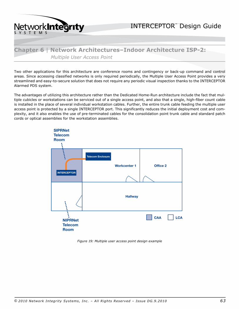
Two other applications for this architecture are conference rooms and contingency or backup command and control areas. Since accessing classified networks is only required periodically, the Multiple User Access Point provides a very streamlined and easytosecure solution that does not require any periodic visual inspection thanks to the INTERCEPTOR Alarmed PDS system.
The advantages of utilizing this architecture rather than the Dedicated HomeRun architecture include the fact that multiple cubicles or workstations can be serviced out of a single access point, and also that a single, highfiber count cable is installed in the place of several individual workstation cables. Further, the entire trunk cable feeding the multiple user access point is protected by a single INTERCEPTOR port. This significantly reduces the initial deployment cost and complexity, and it also enables the use of preterminated cables for the consolidation point trunk cable and standard patch cords or optical assemblies for the workstation assemblies.
Figure 19: Multiple user access point design example
Chapter 6 | Network Architectures–Indoor Architecture ISP2: Multiple User Access Point
Office 2Workcenter 1
Hallway
CAA LCA
SIPRNetTelecom Room
NIPRNet Telecom Room
INTERCEPTOR
Telecom Enclosure
INTERCEPTOR™ Design Guide
© 2010 Network Integrity Systems, Inc. – All Rights Reserved – Issue DG.9.2010 64
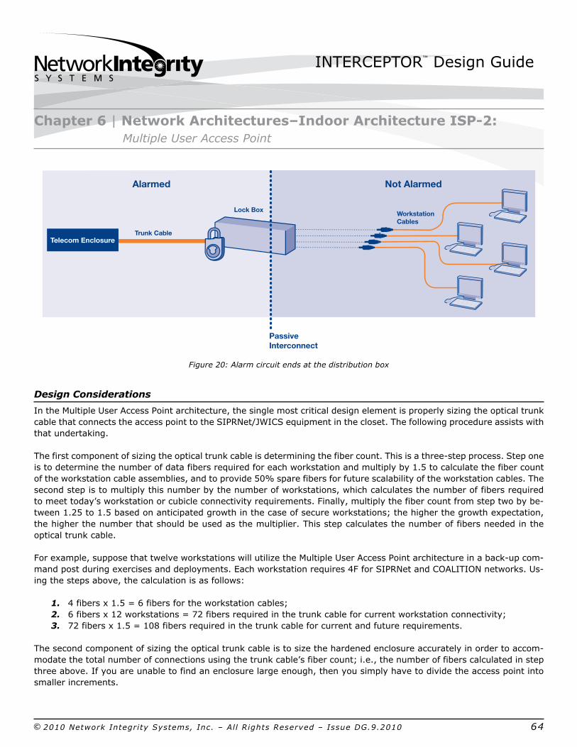
Figure 20: Alarm circuit ends at the distribution box
Design Considerations
In the Multiple User Access Point architecture, the single most critical design element is properly sizing the optical trunk cable that connects the access point to the SIPRNet/JWICS equipment in the closet. The following procedure assists with that undertaking.
The first component of sizing the optical trunk cable is determining the fiber count. This is a threestep process. Step one is to determine the number of data fibers required for each workstation and multiply by 1.5 to calculate the fiber count of the workstation cable assemblies, and to provide 50% spare fibers for future scalability of the workstation cables. The second step is to multiply this number by the number of workstations, which calculates the number of fibers required to meet today’s workstation or cubicle connectivity requirements. Finally, multiply the fiber count from step two by between 1.25 to 1.5 based on anticipated growth in the case of secure workstations; the higher the growth expectation, the higher the number that should be used as the multiplier. This step calculates the number of fibers needed in the optical trunk cable.
For example, suppose that twelve workstations will utilize the Multiple User Access Point architecture in a backup command post during exercises and deployments. Each workstation requires 4F for SIPRNet and COALITION networks. Using the steps above, the calculation is as follows:
1. 4 fibers x 1.5 = 6 fibers for the workstation cables; 2. 6 fibers x 12 workstations = 72 fibers required in the trunk cable for current workstation connectivity; 3. 72 fibers x 1.5 = 108 fibers required in the trunk cable for current and future requirements.
The second component of sizing the optical trunk cable is to size the hardened enclosure accurately in order to accommodate the total number of connections using the trunk cable’s fiber count; i.e., the number of fibers calculated in step three above. If you are unable to find an enclosure large enough, then you simply have to divide the access point into smaller increments.
Chapter 6 | Network Architectures–Indoor Architecture ISP2: Multiple User Access Point
Lock Box Workstation Cables
Alarmed Not Alarmed
Passive Interconnect
Trunk CableTelecom Enclosure
INTERCEPTOR™ Design Guide
© 2010 Network Integrity Systems, Inc. – All Rights Reserved – Issue DG.9.2010 65
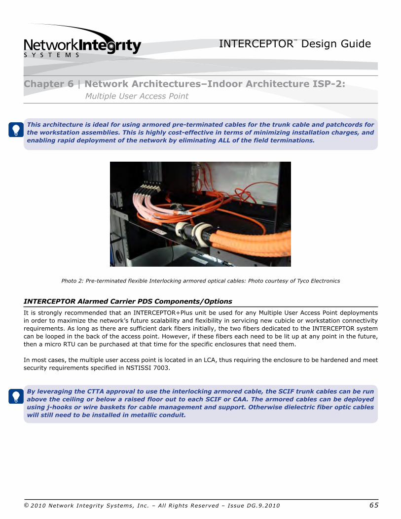
This architecture is ideal for using armored preterminated cables for the trunk cable and patchcords for the workstation assemblies. This is highly costeffective in terms of minimizing installation charges, and enabling rapid deployment of the network by eliminating ALL of the field terminations.
Photo 2: Preterminated flexible Interlocking armored optical cables: Photo courtesy of Tyco Electronics
INTERCEPTOR Alarmed Carrier PDS Components/Options
It is strongly recommended that an INTERCEPTOR+Plus unit be used for any Multiple User Access Point deployments in order to maximize the network’s future scalability and flexibility in servicing new cubicle or workstation connectivity requirements. As long as there are sufficient dark fibers initially, the two fibers dedicated to the INTERCEPTOR system can be looped in the back of the access point. However, if these fibers each need to be lit up at any point in the future, then a micro RTU can be purchased at that time for the specific enclosures that need them.
In most cases, the multiple user access point is located in an LCA, thus requiring the enclosure to be hardened and meet security requirements specified in NSTISSI 7003.
By leveraging the CTTA approval to use the interlocking armored cable, the SCIF trunk cables can be run above the ceiling or below a raised floor out to each SCIF or CAA. The armored cables can be deployed using jhooks or wire baskets for cable management and support. Otherwise dielectric fiber optic cables will still need to be installed in metallic conduit.
Chapter 6 | Network Architectures–Indoor Architecture ISP2: Multiple User Access Point
INTERCEPTOR™ Design Guide
© 2010 Network Integrity Systems, Inc. – All Rights Reserved – Issue DG.9.2010 66
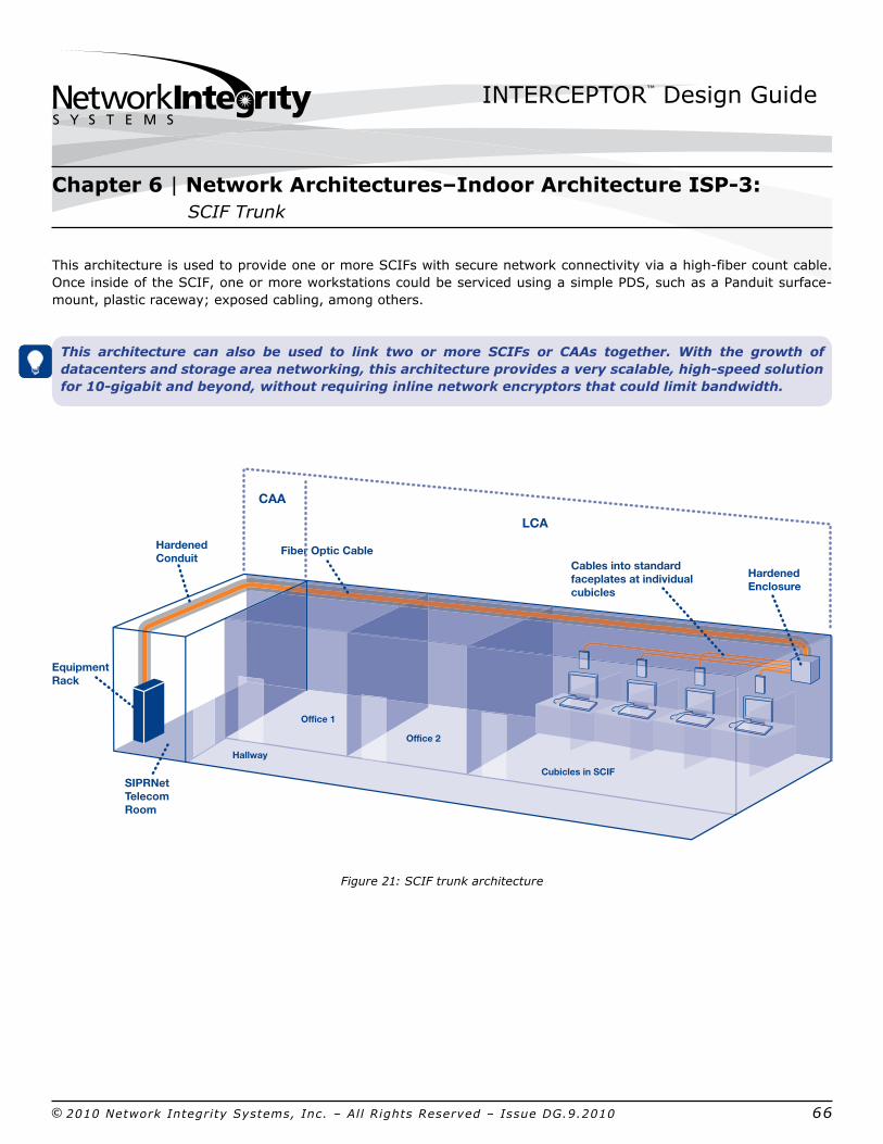
This architecture is used to provide one or more SCIFs with secure network connectivity via a highfiber count cable. Once inside of the SCIF, one or more workstations could be serviced using a simple PDS, such as a Panduit surfacemount, plastic raceway; exposed cabling, among others.
This architecture can also be used to link two or more SCIFs or CAAs together. With the growth of datacenters and storage area networking, this architecture provides a very scalable, highspeed solution for 10gigabit and beyond, without requiring inline network encryptors that could limit bandwidth.
Figure 21: SCIF trunk architecture
Chapter 6 | Network Architectures–Indoor Architecture ISP3: SCIF Trunk
Hardened Enclosure
Cables into standard faceplates at individual cubicles
Cubicles in SCIF
Office 1
Office 2
Hallway
SIPRNet Telecom Room
Equipment Rack
Hardened Conduit
Fiber Optic Cable
LCA
CAA
INTERCEPTOR™ Design Guide
© 2010 Network Integrity Systems, Inc. – All Rights Reserved – Issue DG.9.2010 67
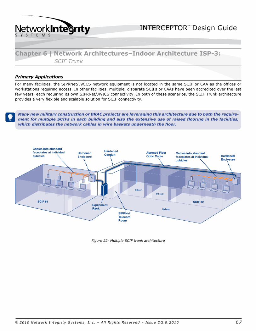
Primary Applications
For many facilities, the SIPRNet/JWICS network equipment is not located in the same SCIF or CAA as the offices or workstations requiring access. In other facilities, multiple, disparate SCIFs or CAAs have been accredited over the last few years, each requiring its own SIPRNet/JWICS connectivity. In both of these scenarios, the SCIF Trunk architecture provides a very flexible and scalable solution for SCIF connectivity.
Many new military construction or BRAC projects are leveraging this architecture due to both the requirement for multiple SCIFs in each building and also the extensive use of raised flooring in the facilities, which distributes the network cables in wire baskets underneath the floor.
Figure 22: Multiple SCIF trunk architecture
Chapter 6 | Network Architectures–Indoor Architecture ISP3: SCIF Trunk
SCIF #2
Office 1
Office 2
Hallway
SCIF #1
Hardened Enclosure
Cables into standard faceplates at individual cubicles
SIPRNet Telecom Room
Equipment Rack
Hardened Conduit
Alarmed Fiber Optic Cable
Hardened Enclosure
Cables into standard faceplates at individual cubicles

INTERCEPTOR™ Design Guide
© 2010 Network Integrity Systems, Inc. – All Rights Reserved – Issue DG.9.2010 68
Design Considerations
When designing a network using this architecture, there are only two primary design considerations: (1) ensuring that the SIPRNet/JWICS network equipment is protected, and (2) determining the fiber count of the SCIF trunk cables. The alarmed SCIF trunk cables will terminate inside of the SCIFs or CAAs.
Consideration 1: Ensuring the SIPRNET/JWICS Network Equipment is Protected
For facilities with one or more SCIFs or CAAs, the SIPRNet/JWICS network equipment is often located in either one one of the primary SCIFs or inside an independent red/black equipment room that is not attached to any SCIF. In both of these circumstances, the SIPRNet/JWICS network equipment can be installed without any additional protec tion. However, in some other facilities where SCIFs are only now being accredited, the SIPRNet/JWICS equipment may be installed inside of an IPS container near or inside of the LAN equipmentr or telecommunications closet.
Consideration 2: Determining the Fiber Count of the SCIF Trunk Cables
In addition to the number of fibers required for SIPRNet/JWICS workstation connectivity and future growth, two dark fibers in each SCIF trunk cable should be allocated and dedicated to INTERCEPTOR Alarmed PDS monitoring. This can be accomplished by adding two additional fibers to the total number of fibers required for initial workstation connectivity as well as future growth. This can usually be between two and twelve fibers per workstation depending on the number of networks and ports required for each workstation or office. By dedicating two fibers, you can make use of a basic INTERCEPTOR unit and loop the fibers inside of the SCIF zone box or enclosure.
By leveraging the CTTA approval to use the interlocking armored cable, the SCIF trunk cables can be run above the ceiling or below a raised floor out to each SCIF or CAA. The armored cables can be deployed using jhooks or wire baskets for cable management and support underneath the floor.
WARNING: If the potential exists in the future to activate the dark fibers originally dedicated to the INTERCEPTOR for monitoring, then it is recommended that an INTERCEPTOR+Plus unit be installed. RTUs can be added at the time the dark fibers are activiated.
Chapter 6 | Network Architectures–Indoor Architecture ISP3: SCIF Trunk

INTERCEPTOR™ Design Guide
© 2010 Network Integrity Systems, Inc. – All Rights Reserved – Issue DG.9.2010 69
Fiber Count Calculation Example
A facility recently had two new SCIFs (SCIF B and SCIF C, e.g.) accredited and wants to provide SECRET connectivity to both of these from the SIPRNET switch located in the facility’s original SCIF (e.g., SCIF A). Each of the two new SCIFs have different workstation connectivity requirements, and the facility intends on having fifty percent growth over the current requirement.
SCIF B Trunk Cable SCIF C Trunk Cable
SIPRNET Ports Required per Workstation 6 ports (total: 12F) 2 ports (total: 4F)
Number of SCIF Workstations x10 (total: 120F) x15 (total: 60F)Requiring SIPRNET Access 50% Fiber Spares for Future Workstations x60F (total: 180F) x30F (total: 90F)Plus Growth
Dedicated Fibers for INTERCEPTOR xMinimum 2F (Total: 182F) xMinimum 2F (Total: 92F)
Roundup SCIF Trunk Cable Fiber Count 182F to 216F Cable needed 92F to 96F Cable neededto Standard Cable Size
Total Number of Fiber 432 Connectors 192 ConnectorsTerminations Required
Table 6:Fiber Count Calculations
Preterminated cables are an optimal choice for this SCIF Trunk Cable architecture. These cables are cut to length and preterminated in the factory with a variety of connector types (e.g., SC, ST, LC, MTP, Keyed LC, among others). Rather than trunk cables taking two or three days to terminate, preterminated cables can be easily installed and plugged into panels or modules in less than a day. For buildings with accredited SCIFs, the use of preterminated cables minimizes the disruption to ongoing operations, and it eliminates the need to dedicate personnel to escorting the installers. Often, preterminated cables can be pulled in by contractors, but plugged into panels or modules by government personnel.
Chapter 6 | Network Architectures–Indoor Architecture ISP3: SCIF Trunk
INTERCEPTOR™ Design Guide
© 2010 Network Integrity Systems, Inc. – All Rights Reserved – Issue DG.9.2010 70
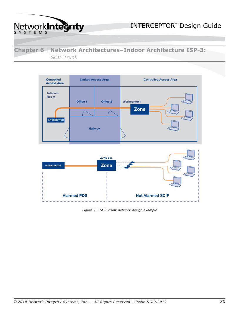
Figure 23: SCIF trunk network design example
Chapter 6 | Network Architectures–Indoor Architecture ISP3: SCIF Trunk
Office 2Office 1 Workcenter 1
Hallway
Telecom Room
Office 2Office 1
Hallway
Workcenter 1
Telecom Room
Limited Access Area
Alarmed PDS
Controlled Access AreaControlled Access Area
ZONE Box
INTERCEPTOR
INTERCEPTOR Zone
Zone
Not Alarmed SCIF
INTERCEPTOR™ Design Guide
© 2010 Network Integrity Systems, Inc. – All Rights Reserved – Issue DG.9.2010 71
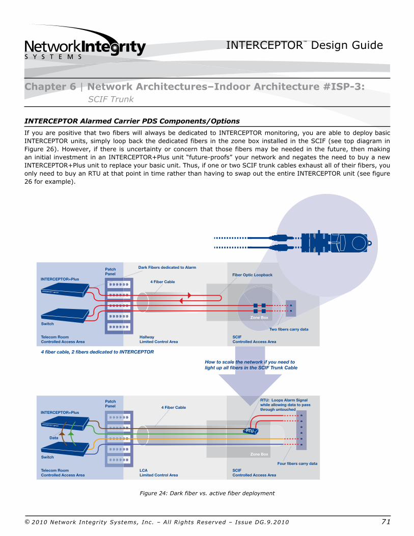
INTERCEPTOR Alarmed Carrier PDS Components/Options
If you are positive that two fibers will always be dedicated to INTERCEPTOR monitoring, you are able to deploy basic INTERCEPTOR units, simply loop back the dedicated fibers in the zone box installed in the SCIF (see top diagram in Figure 26). However, if there is uncertainty or concern that those fibers may be needed in the future, then making an initial investment in an INTERCEPTOR+Plus unit “futureproofs” your network and negates the need to buy a new INTERCEPTOR+Plus unit to replace your basic unit. Thus, if one or two SCIF trunk cables exhaust all of their fibers, you only need to buy an RTU at that point in time rather than having to swap out the entire INTERCEPTOR unit (see figure 26 for example).
Figure 24: Dark fiber vs. active fiber deployment
Chapter 6 | Network Architectures–Indoor Architecture #ISP3: SCIF Trunk
4 fiber cable, 2 fibers dedicated to INTERCEPTOR
How to scale the network if you need to light up all fibers in the SCIF Trunk Cable
4 fiber cable, all fibers dedicated to INTERCEPTOR
Telecom RoomControlled Access Area
Two fibers carry data
4 Fiber Cable
Zone Box
Zone Box
Dark Fibers dedicated to Alarm
Switch
PatchPanel
PatchPanel
INTERCEPTOR+Plus
INTERCEPTOR™ +PLUS
HallwayLimited Control Area
SCIFControlled Access Area
RTU: Loops Alarm Signal while allowing data to pass through untouched
Telecom RoomControlled Access Area
Four fibers carry data
4 Fiber Cable
Switch
INTERCEPTOR+Plus
INTERCEPTOR™ +PLUS
LCALimited Control Area
SCIFControlled Access Area
the network ibers in the SCI
Data
Fiber Optic Loopback
RTU

INTERCEPTOR™ Design Guide
© 2010 Network Integrity Systems, Inc. – All Rights Reserved – Issue DG.9.2010 72
As long as there are dark fibers in the workstation drop cable, you can install a fiber loopack behind the bulkhead in the SCIF zone box or enclosure. This way, the SIPRNet/JWICS fibers terminate into the bulkhead, but the alarmed fibers are looped beind it, thus preventing any potential alarms caused by end users moving their patch cables around.
Figure 25: Examples of typical zone boxes and enclosures
WARNING: Depending on the existing physical security and/or compensating measures, the DAA may require a hardened enclosure to be installed and may alter the use of a commercial zone box instead.
Scalability of INTERCEPTOR Equipment
In this architecture, one INTERCEPTOR port is used to protect all of the fibers in the SCIF trunk cable. Therefore, new INTERCEPTOR ports will only be required if new cables need to be installed to existing SCIFs, such as when adding COALITION or other network, or if new SCIFs are constructed.
If INTERCEPTOR+Plus units were initially deployed, and currently there is a need to light up all of the fibers in the SCIF trunk cables, you can purchase RTUs on a casebycase basis if your SCIF trunk cables exhaust all of their dark fibers (as shown in Figure 26).
Chapter 6 | Network Architectures–Indoor Architecture #ISP3: SCIF Trunk
INTERCEPTOR™ Design Guide
© 2010 Network Integrity Systems, Inc. – All Rights Reserved – Issue DG.9.2010 73
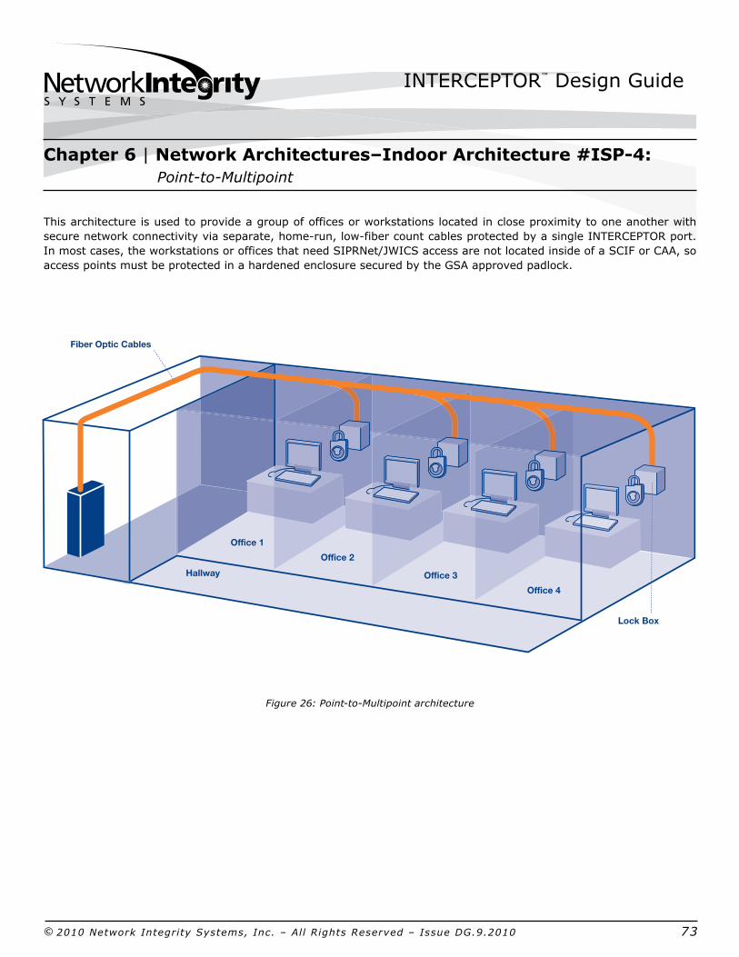
This architecture is used to provide a group of offices or workstations located in close proximity to one another with secure network connectivity via separate, homerun, lowfiber count cables protected by a single INTERCEPTOR port. In most cases, the workstations or offices that need SIPRNet/JWICS access are not located inside of a SCIF or CAA, so access points must be protected in a hardened enclosure secured by the GSA approved padlock.
Figure 26: PointtoMultipoint architecture
Office 1
Office 2
Office 3
Office 4
Hallway
Lock Box
Fiber Optic Cables
Chapter 6 | Network Architectures–Indoor Architecture #ISP4: PointtoMultipoint

INTERCEPTOR™ Design Guide
© 2010 Network Integrity Systems, Inc. – All Rights Reserved – Issue DG.9.2010 74
Primary Applications
With the explosion in SIPRNet and JWICS requirements, many DOD services and government agencies have begun to deploy secure networks throughout their organizations. As a result, there are several buildings that have multiple and disparate users, such as separate workstations or offices that require access to SIPRNet/JWICS.
The advantage that this architecture has over the Dedicated HomeRun architecture is that multiple offices or workstations are all protected by a single INTERCEPTOR port, rather than each office or workstation requiring its own port. This can significantly reduce the initial deployment cost from several thousands of dollars per workstation to less than $1,000 per workstation.
The disadvantage of this approach is that there is no longer alarm granularity—i.e., knowing exactly which workstation cable is in alarm. However, for workstations or offices in close proximity to each another, it is highly likely that all of the network cables are using the same conveyance (conduit, wire baskets, innerduct, pathway, etc.). So if there is an alarm to any of the cables, the inspection route from the INTERCEPTOR through the building would follow exactly the same route.
WARNING: It is critical that this architecture be designed so that any INTERCEPTOR alarm circuit inspection can be completed within the fifteen minutes required in NSTISSI 7003. For example, it is not recommended that four offices located in separate areas of a building using different conveyances to distribute cables be daisychained together. In that case, it would be difficult to respond to an alarm and inspect all four areas within fifteen minutes.
Figure 27: PointtoMultipoint nework design example
Chapter 6 | Network Architectures–Indoor Architecture #ISP4: PointtoMultipoint
Hallway
Office 1 Office 2 Office 3 Office 4
INTERCEPTOR
CAA LCASIPRNetTelecom Room
INTERCEPTOR™ Design Guide
© 2010 Network Integrity Systems, Inc. – All Rights Reserved – Issue DG.9.2010 75
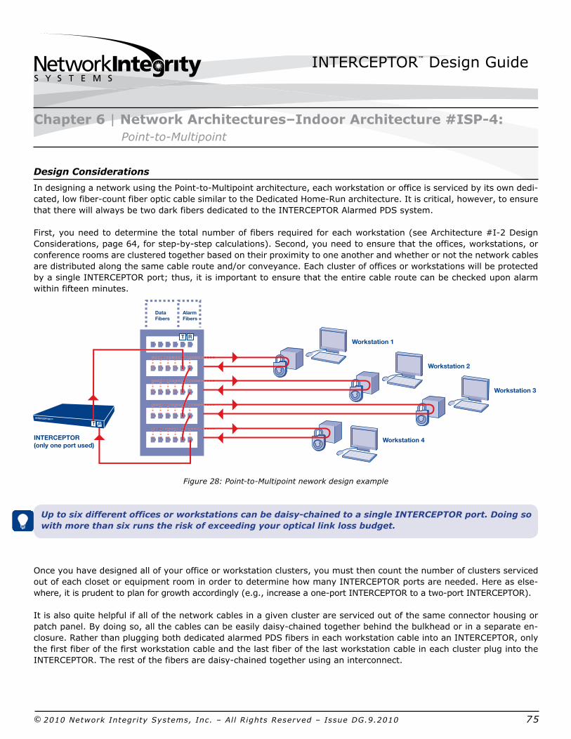
Design Considerations
In designing a network using the PointtoMultipoint architecture, each workstation or office is serviced by its own dedicated, low fibercount fiber optic cable similar to the Dedicated HomeRun architecture. It is critical, however, to ensure that there will always be two dark fibers dedicated to the INTERCEPTOR Alarmed PDS system.
First, you need to determine the total number of fibers required for each workstation (see Architecture #I2 Design Considerations, page 64, for stepbystep calculations). Second, you need to ensure that the offices, workstations, or conference rooms are clustered together based on their proximity to one another and whether or not the network cables are distributed along the same cable route and/or conveyance. Each cluster of offices or workstations will be protected by a single INTERCEPTOR port; thus, it is important to ensure that the entire cable route can be checked upon alarm within fifteen minutes.
Figure 28: PointtoMultipoint nework design example
Up to six different offices or workstations can be daisychained to a single INTERCEPTOR port. Doing so with more than six runs the risk of exceeding your optical link loss budget.
Once you have designed all of your office or workstation clusters, you must then count the number of clusters serviced out of each closet or equipment room in order to determine how many INTERCEPTOR ports are needed. Here as elsewhere, it is prudent to plan for growth accordingly (e.g., increase a oneport INTERCEPTOR to a twoport INTERCEPTOR).
It is also quite helpful if all of the network cables in a given cluster are serviced out of the same connector housing or patch panel. By doing so, all the cables can be easily daisychained together behind the bulkhead or in a separate enclosure. Rather than plugging both dedicated alarmed PDS fibers in each workstation cable into an INTERCEPTOR, only the first fiber of the first workstation cable and the last fiber of the last workstation cable in each cluster plug into the INTERCEPTOR. The rest of the fibers are daisychained together using an interconnect.
Chapter 6 | Network Architectures–Indoor Architecture #ISP4: PointtoMultipoint
INTERCEPTOR(only one port used)
Workstation 1
Workstation 4
Workstation 2
Workstation 3
INTERCEPTOR™
T R
T R
Data Fibers
AlarmFibers

INTERCEPTOR™ Design Guide
© 2010 Network Integrity Systems, Inc. – All Rights Reserved – Issue DG.9.2010 76
Workstation Cluster Fiber Plan Example
In one INTERCEPTOR deployment, multiple division offices are being consolidated in the operations area. Upon evaluating the structured cabling plan, it is determined that four offices can easily be clustered together to be protected by a single INTERCEPTOR port. Each office needs a minimum of two fibers for SECRET level networks. Since two additional fibers are required for INTERCEPTOR, the network manager decides to use a sixfiber interlocking armored cable to each office so that the cables can be run below the raised floor. The following table shows how the fibers in each cable are daisychained together in order to create a single, protected optical circuit.
Optical Fibers in 6Fiber Network Cables
SECRET Data INTERCEPTOR Alarmed PDS
1 2 3 4 5 6
Office #1 (O1) Tx Rx Sp Sp INTERCEPTORTx O2Fiber 5
Office #2 (O2) Tx Rx Sp Sp O1Fiber 6 O3Fiber 5
Office #3 (O3) Tx Rx Sp Sp O2Fiber 6 O4Fiber 5
Office #4 (O4) Tx Rx Sp Sp O3Fiber 6 INTERCEPTORRx
Note: Tx = Data Transmission, Rx = Data Reception, Sp = Spare
Table 7: Fiber Patch Plan
As you can see from the diagram and table above, daisychaining multiple offices or workstations together is a very effective way to reduce deployment costs and minimize the number of INTERCEPTOR ports required.
Whenever possible, it is recommended that the daisychaining of fibers be done behind a bulkhead or in a separate enclosure to minimize the possibility of alarms being caused by technicians moving patch cords or patching in new equipment.
Chapter 6 | Network Architectures–Indoor Architecture #ISP4: PointtoMultipoint
INTERCEPTOR™ Design Guide
© 2010 Network Integrity Systems, Inc. – All Rights Reserved – Issue DG.9.2010 77
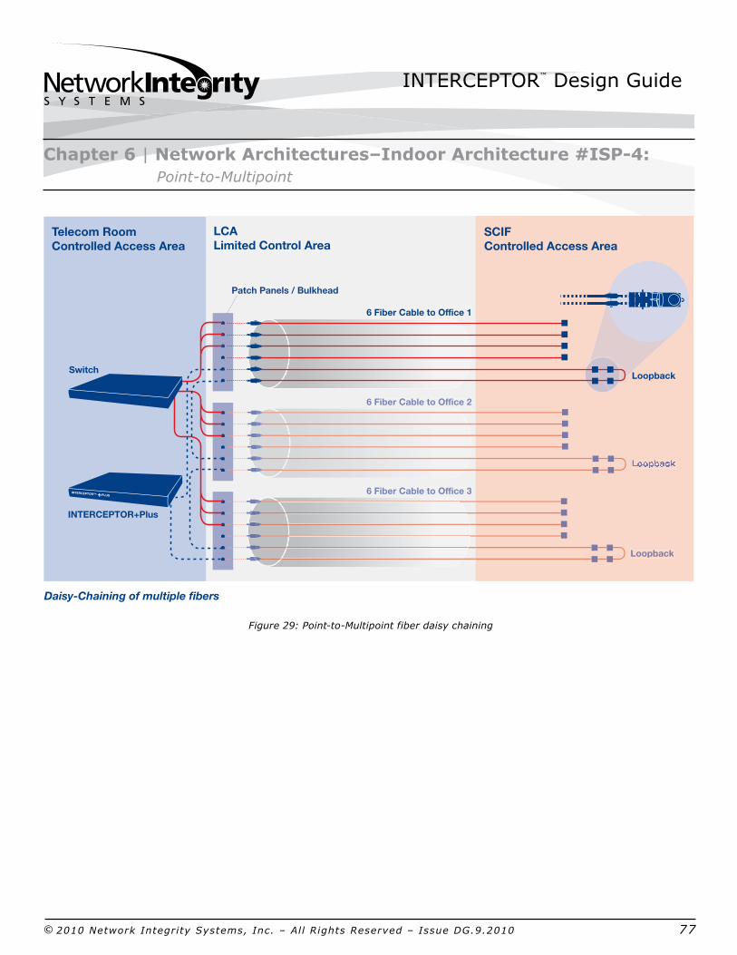
Figure 29: PointtoMultipoint fiber daisy chaining
Chapter 6 | Network Architectures–Indoor Architecture #ISP4: PointtoMultipoint
Patch Panels / BulkheadPatch Panels / Bulkhead
Daisy-Chaining of multiple fibers
Telecom RoomControlled Access Area
6 Fiber Cable to Office 1
6 Fiber Cable to Office 2
6 Fiber Cable to Office 3
Switch
INTERCEPTOR+Plus
INTERCEPTOR™ +PLUS
LCALimited Control Area
Loopback
Loopback
SCIFControlled Access Area

INTERCEPTOR™ Design Guide
© 2010 Network Integrity Systems, Inc. – All Rights Reserved – Issue DG.9.2010 78
INTERCEPTOR Alarmed Carriers PDS Components/Options
Whenever optical cables are daisychained together to make use of a single INTERCEPTOR port, those fibers must be dark and 100% dedicated to the INTERCEPTOR system. In most cases, a basic INTERCPETOR unit can be used. However, if other architectures are going to be supported out of the same INTERCEPTOR, then an INTERCEPTOR+Plus unit may be used.
WARNING: Information security guidance specifically prohibits the transmission of classified national security information to anyone other than the intended recipient. Therefore, Micro RTUs may not be used in this architecture.
Since dark fibers in the workstation cables are being daisychanned, you must install a fiber loopback behind both the faceplate in the workstation enclosure and also the bulkhead in the connector housing for those fibers not connecting to the INTERCEPTOR (see the fiber map exercise above). This way, the SIPRNet/JWICS data fibers terminate into the bulkhead, but the alarmed fibers are looped behind it, thus preventing any potential alarms caused by end users moving their patch cables around.
Depending on the security classification of the offices, either a hardened enclosure (for LCAs) or a standard faceplate (for CAAs) must be installed in the offices.
Scalability of INTERCEPTOR Equipment
In this architecture, one INTERCEPTOR port is used to protect multiple workstation cables. So, if new requirements emerge for additional workstations or offices, either add the new workstation or office to an existing cluster by daisychaining the fibers in the cable into the existing fiber map, or start a new cluster, which would require an additional INTERCEPTOR port. Consider the design criteria for clustering workstations and offices.
If at some point in time you need more fibers per workstation, you cannot use a micro RTU in this architecture. A larger fiber count cable will have to be installed for those workstations where fiber exhaust is an issue in order to maintain the dedicated fibers for the INTERCEPTOR system.
Chapter 6 | Network Architectures–Indoor Architecture #ISP4: PointtoMultipoint

INTERCEPTOR™ Design Guide
© 2010 Network Integrity Systems, Inc. – All Rights Reserved – Issue DG.9.2010 79
This architecture is used to provide one or more clusters of offices or workstations located in close proximity to each another with secure network connectivity via a single highfiber count trunk cable. As in the PointtoMultipoint architecture, each individual cluster is protected by a single INTERCEPTOR port. The consolidation point serves as a permanent interconnect between the highfiber count trunk cable and the disparate, lowfiber count workstation cables in this architecture. The INTERCEPTOR protects the entire network link from the closet to each individual workstation.
For offices or workstations in close proximity to the SIPRNet/JWICS equipment room, the PointtoMultipoint architecture may be a more cost efficient option.
In most cases, neither the consolidation point nor the workstations or offices that need SIPRNet/JWICS access are located inside of a SCIF or CAA. If so, hardened enclosures secured with the GSA approved highsecurity padlock (as mentioned previously) must be used.
Figure 30: Consolidation point architecture
Chapter 6 | Network Architectures–Indoor Architecture #ISP5: Consolidation Point
LCA
CAA
Office 1
Office 2
Office 3
Hallway
Lock Box
ConsolidationPointEnclosure
Fiber Optic Cables
SIPRNet Telecom Room
Equipment Rack
INTERCEPTOR™ Design Guide
© 2010 Network Integrity Systems, Inc. – All Rights Reserved – Issue DG.9.2010 80
Primary Applications
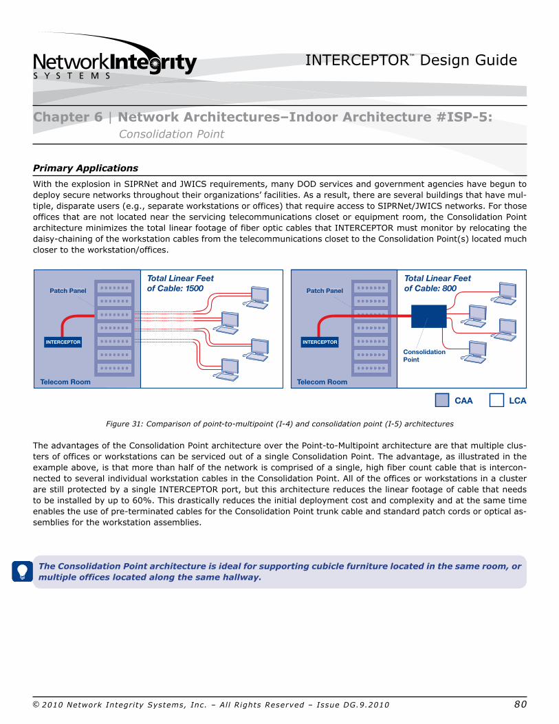
With the explosion in SIPRNet and JWICS requirements, many DOD services and government agencies have begun to deploy secure networks throughout their organizations’ facilities. As a result, there are several buildings that have multiple, disparate users (e.g., separate workstations or offices) that require access to SIPRNet/JWICS networks. For those offices that are not located near the servicing telecommunications closet or equipment room, the Consolidation Point architecture minimizes the total linear footage of fiber optic cables that INTERCEPTOR must monitor by relocating the daisychaining of the workstation cables from the telecommunications closet to the Consolidation Point(s) located much closer to the workstation/offices.
Figure 31: Comparison of pointtomultipoint (I4) and consolidation point (I5) architectures
The advantages of the Consolidation Point architecture over the PointtoMultipoint architecture are that multiple clusters of offices or workstations can be serviced out of a single Consolidation Point. The advantage, as illustrated in the example above, is that more than half of the network is comprised of a single, high fiber count cable that is interconnected to several individual workstation cables in the Consolidation Point. All of the offices or workstations in a cluster are still protected by a single INTERCEPTOR port, but this architecture reduces the linear footage of cable that needs to be installed by up to 60%. This drastically reduces the initial deployment cost and complexity and at the same time enables the use of preterminated cables for the Consolidation Point trunk cable and standard patch cords or optical assemblies for the workstation assemblies.
The Consolidation Point architecture is ideal for supporting cubicle furniture located in the same room, or multiple offices located along the same hallway.
Chapter 6 | Network Architectures–Indoor Architecture #ISP5: Consolidation Point
Patch Panel Patch PanelPatch Panel
Telecom Room
Total Linear Feetof Cable: 1500
Total Linear Feetof Cable: 800Patch Panel
Telecom Room
Consolidation Point
INTERCEPTOR INTERCEPTOR
CAA LCA

INTERCEPTOR™ Design Guide
© 2010 Network Integrity Systems, Inc. – All Rights Reserved – Issue DG.9.2010 81
Figure 32: Consolidation poing architecture under floor
Design Considerations
In the Consolidation Point architecture, each workstation or office is serviced by its own dedicated, low fiber count cable similar to that of the PointtoMultipoint architecture; however, instead of the workstation cables terminating in the telecommunications closet or equipment room, they terminate in the Consolidation Point which is located in close proximity to the workstations or offices. Rather than daisychaining the workstation cables in the equipment room, it is done in the Consolidation Point, where the workstation cables are interconnected to the highfiber count trunk cable. Therefore, it is critical to ensure that there will always be two dark fibers dedicated to the INTERCEPTOR system in both the workstation cables as well as the Consolidation Point trunk cable.
The first step is to determine the total number of fibers required for each workstation (i.e., SIPRNet/JWICS requirement plus future growth plus two INTERCEPTOR fibers; see the detailed explanation in the SCIF Trunk architecture discussion above). The second step is locating the consolidation point in close proximity to the cluster or clusters of offices or workstations. Since one consolidation point can serve multiple clusters of offices or workstations, it may be necessary to place the consolidation point at the same distance from each of the clusters. The final step is to calculate the fiber count for the consolidation point trunk cable (i.e., the sum of the fiber count from all of the workstation cables plus 50% future growth plus two INTERCEPTOR fibers for each cluster).
Chapter 6 | Network Architectures–Indoor Architecture #ISP5: Consolidation Point
Office 1Office 2
Office 3Office 4
Hallway
Lock BoxFiber Optic Cable
Telecom Room
Equipment Rack
ConsolidationPoint
5 10 15 ... 100 110 120 130 140 150 160...
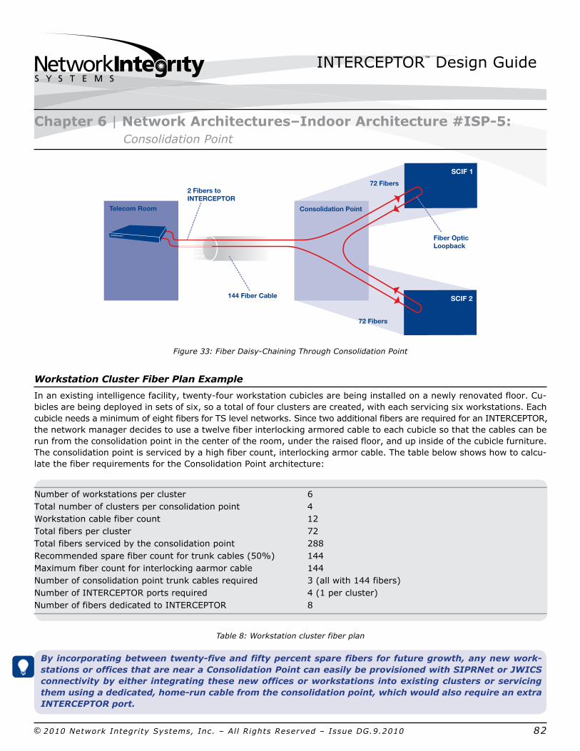
INTERCEPTOR™ Design Guide
© 2010 Network Integrity Systems, Inc. – All Rights Reserved – Issue DG.9.2010 82
Figure 33: Fiber DaisyChaining Through Consolidation Point
Workstation Cluster Fiber Plan Example
In an existing intelligence facility, twentyfour workstation cubicles are being installed on a newly renovated floor. Cubicles are being deployed in sets of six, so a total of four clusters are created, with each servicing six workstations. Each cubicle needs a minimum of eight fibers for TS level networks. Since two additional fibers are required for an INTERCEPTOR, the network manager decides to use a twelve fiber interlocking armored cable to each cubicle so that the cables can be run from the consolidation point in the center of the room, under the raised floor, and up inside of the cubicle furniture. The consolidation point is serviced by a high fiber count, interlocking armor cable. The table below shows how to calculate the fiber requirements for the Consolidation Point architecture:
Number of workstations per cluster 6 Total number of clusters per consolidation point 4 Workstation cable fiber count 12 Total fibers per cluster 72 Total fibers serviced by the consolidation point 288 Recommended spare fiber count for trunk cables (50%) 144 Maximum fiber count for interlocking aarmor cable 144 Number of consolidation point trunk cables required 3 (all with 144 fibers) Number of INTERCEPTOR ports required 4 (1 per cluster) Number of fibers dedicated to INTERCEPTOR 8
Table 8: Workstation cluster fiber plan
By incorporating between twentyfive and fifty percent spare fibers for future growth, any new workstations or offices that are near a Consolidation Point can easily be provisioned with SIPRNet or JWICS connectivity by either integrating these new offices or workstations into existing clusters or servicing them using a dedicated, homerun cable from the consolidation point, which would also require an extra INTERCEPTOR port.
Chapter 6 | Network Architectures–Indoor Architecture #ISP5: Consolidation Point
Fiber Optic Loopback
Telecom Room
2 Fibers toINTERCEPTOR
144 Fiber Cable
Consolidation Point
72 Fibers
72 Fibers
SCIF 1
SCIF 2
INTERCEPTOR™

INTERCEPTOR™ Design Guide
© 2010 Network Integrity Systems, Inc. – All Rights Reserved – Issue DG.9.2010 83
Multiple consolidation point trunk cables may be required depending on the number of fibers serviced out of the consolidation point and the maximum fiber count in which the interlocking armored cable is available, either 72 or 144 fibers (depends on manufacturers of armored cable).
WARNING: It may be necessary to split or reduce the number of workstations or offices or clusters serviced out of a single consolidation point due to the physical dimensions that may be required to provide the interconnection of the trunk and workstation cables. Up to 288 fibers can be interconnected in a single 4RU or wallmount housing using LC connectors. Consolidation point sizing should be done based on the total number of fibers in the trunk cables—rather than the workstation cables—in order to ensure that there is enough scalability of the consolidation point to meet future requirements.
Just as in the PointtoMultipoint architecture, the fibers in each cluster’s workstation cables are concatenated together and then connected to the two dedicated fibers in the consolidation point trunk cable that provide the incoming and outgoing alarmed PDS signal from a single INTERCEPTOR port (see the diagram below). Thus, you need one INTERCEPTOR port and two dedicated fibers in the trunk cable for each cluster.
Figure 34: Consolidation Point Servicing 4 DaisyChained Clusters
Chapter 6 | Network Architectures–Indoor Architecture #ISP5: Consolidation Point
SCIF 4
SCIF 1
Fiber Optic Loopback
Consolidation Point
SCIF 2
SCIF 3High Fiber Count Trunk Cable
Telecom Room
Out to SCIF 1
INTERCEPTOR™
TelecomRoom
INTERCEPTO
In from SCIF 4
2 Fibers toINTERCEPTOR
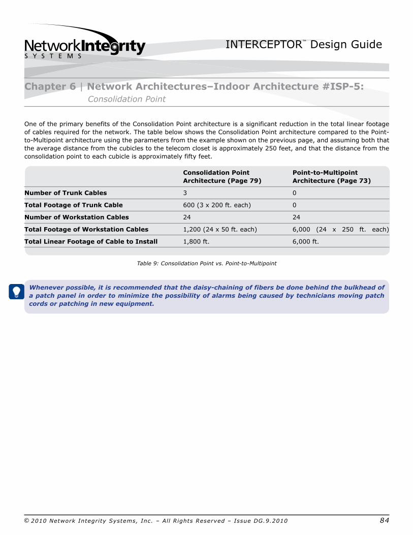
INTERCEPTOR™ Design Guide
© 2010 Network Integrity Systems, Inc. – All Rights Reserved – Issue DG.9.2010 84
Chapter 6 | Network Architectures–Indoor Architecture #ISP5: Consolidation Point
One of the primary benefits of the Consolidation Point architecture is a significant reduction in the total linear footage of cables required for the network. The table below shows the Consolidation Point architecture compared to the PointtoMultipoint architecture using the parameters from the example shown on the previous page, and assuming both that the average distance from the cubicles to the telecom closet is approximately 250 feet, and that the distance from the consolidation point to each cubicle is approximately fifty feet.
Consolidation Point PointtoMultipoint
Architecture (Page 79) Architecture (Page 73)
Number of Trunk Cables 3 0
Total Footage of Trunk Cable 600 (3 x 200 ft. each) 0
Number of Workstation Cables 24 24
Total Footage of Workstation Cables 1,200 (24 x 50 ft. each) 6,000 (24 x 250 ft. each)
Total Linear Footage of Cable to Install 1,800 ft. 6,000 ft.
Table 9: Consolidation Point vs. PointtoMultipoint
Whenever possible, it is recommended that the daisychaining of fibers be done behind the bulkhead of a patch panel in order to minimize the possibility of alarms being caused by technicians moving patch cords or patching in new equipment.
INTERCEPTOR™ Design Guide
© 2010 Network Integrity Systems, Inc. – All Rights Reserved – Issue DG.9.2010 85
INTERCEPTOR Alarmed Carrier PDS Components/Options
Even though workstation or offices are being initially clustered together out of a consolidation point, it is strongly recommended that an INTERCEPTOR+Plus unit be used for any Consolidation Point architecture so as to maximize the future scalability and flexibility of servicing new offices or cubicles directly out of existing consolidation points.
WARNING: Information security guidance specifically prohibits the transmission of classified national security information to anyone other than the intended recipient. Micro RTUs thus may not be used in this architecture.
Since the dark fibers in the workstation cables are being daisychained, you must install a fiber loopback behind the faceplate in the workstation enclosure as well as behind the bulkhead in the consolidation point for those fibers not connecting to incoming or outgoing INTERCEPTOR fibers in the trunk cable or cables. By doing so, the SIPRNet/JWICS data fibers terminate into the bulkhead of the consolidation point, but the alarmed fibers are looped behind it, which prevents any potential alarms caused by end users moving patch cables around or the addition of a new workstation or office.
Assuming that the cubicles or offices are not located inside of a SCIF or LCA, a hardened enclosure would be required in the offices.
Scalability of INTERCEPTOR Equipment
In this architecture, one INTERCEPTOR port is used to protect multiple workstation cables. Therefore, if new requirements emerge for additional workstations or offices, you can either attempt to add the new workstation or office to an existing cluster by daisychaining the fibers in the cable into the existing fiber map, or install a dedicated workstation cable for the new workstation or office which would also require an additional, dedicated INTERCEPTOR port.
WARNING: If more fibers are ever needed per workstation, you cannot use a Micro RTU in this architecture. A larger fiber count cable will have to be installed for those workstations where fiber exhaust is an issue in order to maintain the dedicated fibers for the INTERCEPTOR.
Chapter 6 | Network Architectures–Indoor Architecture #ISP5: Consolidation Point

INTERCEPTOR™ Design Guide
© 2010 Network Integrity Systems, Inc. – All Rights Reserved – Issue DG.9.2010 86
Indoor Architecture #I6: Hybrid
This architecture leverages both hardened carrier and alarmed carrier PDS technology to deliver SIPRNet/JWICS connectivity to a set of workstations, cubicles, or offices. From the SIPRNet/JWICS network equipment, an INTERCEPTOR Alarmed PDS would protect the network out to a consolidation point, but rather than the workstation cables being alarmed, they are instead protected inside of a hardened carrier.
Figure 35: Hybrid Architecture
Chapter 6 | Network Architectures–Indoor Architecture #ISP6: Hybrid
Hallway
ConsolidationPoint
Hardened Enclosure
Alarmed Fiber Optic Cables
Telecom Room
Equipment Rack
Lock Box
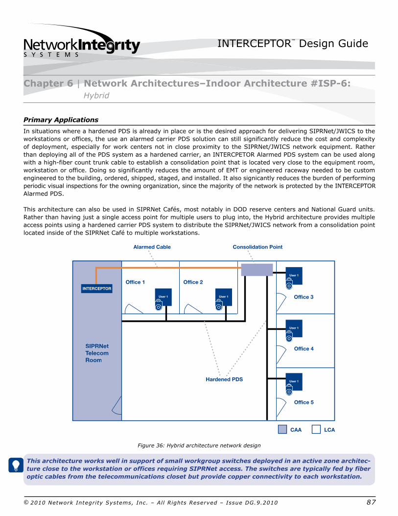
INTERCEPTOR™ Design Guide
© 2010 Network Integrity Systems, Inc. – All Rights Reserved – Issue DG.9.2010 87
Primary Applications
In situations where a hardened PDS is already in place or is the desired approach for delivering SIPRNet/JWICS to the workstations or offices, the use an alarmed carrier PDS solution can still significantly reduce the cost and complexity of deployment, especially for work centers not in close proximity to the SIPRNet/JWICS network equipment. Rather than deploying all of the PDS system as a hardened carrier, an INTERCPETOR Alarmed PDS system can be used along with a highfiber count trunk cable to establish a consolidation point that is located very close to the equipment room, workstation or office. Doing so significantly reduces the amount of EMT or engineered raceway needed to be custom engineered to the building, ordered, shipped, staged, and installed. It also signicantly reduces the burden of performing periodic visual inspections for the owning organization, since the majority of the network is protected by the INTERCEPTOR Alarmed PDS.
This architecture can also be used in SIPRNet Cafés, most notably in DOD reserve centers and National Guard units. Rather than having just a single access point for multiple users to plug into, the Hybrid architecture provides multiple access points using a hardened carrier PDS system to distribute the SIPRNet/JWICS network from a consolidation point located inside of the SIPRNet Café to multiple workstations.
Figure 36: Hybrid architecture network design
This architecture works well in support of small workgroup switches deployed in an active zone architecture close to the workstation or offices requiring SIPRNet access. The switches are typically fed by fiber optic cables from the telecommunications closet but provide copper connectivity to each workstation.
Chapter 6 | Network Architectures–Indoor Architecture #ISP6: Hybrid
Office 1
Hardened PDS
Alarmed Cable Consolidation Point
Office 2
Office 3
Office 4
Office 5
SIPRNetTelecom Room
SIPRNetTelecomRoom
INTERCEPTOR
User 1 User 1
User 1
User 1
User 1
CAA LCA
INTERCEPTOR™ Design Guide
© 2010 Network Integrity Systems, Inc. – All Rights Reserved – Issue DG.9.2010 88
Design Considerations
In the Hybrid architecture, the first design element to consider is the proper sizing of the optical trunk cable that connects the consolidation point to the SIPRNet/JWICS equipment in the closet. The process defined above in #I2: Multiple User Access Point, can be used to determine the fiber count required.
By leveraging the CTTA approval to use the interlocking armored cable with the INTERCEPTOR system, the trunk cables can be run above the ceiling or below a raised floor out to the consolidation point. The armored cables can be deployed using jhooks or wire baskets for cable management and support.
Inside the consolidation point, the highfiber count trunk cable is interconnected to the individual workstation cables. The enclosure must be sized according to the maximum number of fiber connections that the trunk cable can support. Because the INTERCEPTOR system ends and the hardened carrier system begins at the consolidation point, the enclosure must be located below the ceiling using the criteria for a hardened carrier PDS system specified in NSTISSI 7003.
From the consolidation point to the workstations, a hardened carrier PDS system is used to protect the network drops. The network terminates in a hardened workstation enclosure that must be secure with the GSA approved padlock.
INTERCEPTOR Alarmed Carriers PDS Components/Options
Either an INTERCEPTOR or an INTERCEPTOR+Plus unit can be used for Hybrid deployments. As long as there are sufficient dark fibers included in the trunk cable and two fibers can be dedicated to the INTERCEPTOR system, a standard INTERCEPTOR unit may be used and the alarmed fibers can be looped in the consolidation point. However, if there is any concern that the fibers may eventually need to be activated, then an INTERCEPTOR+Plus unit should be installed so that a micro RTU can be purchased if needed.
In almost all cases, a hybrid consolidation point is located in an LCA, thus requiring the enclosure to be hardened and meet the security requirements specified in NSTISSI 7003.
Scalability of INTERCEPTOR Equipment
In this architecture, one INTERCEPTOR port is used to protect the trunk cable out to the hybrid consolidation point. Therefore, if new requirements emerge for additional work centers or areas of the building, a new hybrid consolidation point can be created, connected to a new trunk cable, and protected with an open or additional INTERCEPTOR port.
Chapter 6 | Network Architectures–Indoor Architecture #ISP6: Hybrid

INTERCEPTOR™ Design Guide
© 2010 Network Integrity Systems, Inc. – All Rights Reserved – Issue DG.9.2010 89
The Contingency/Temporary Facility architecture combines the “SCIFinabox” approach of an IPS container with the flexibility of an INTERCEPTOR system, using armored cables, to provide SIPRNet/JWICS connectivity to contingency or temporary complexes comprised of trailers, modular facilities, or tents, for example.
Figure 37: Contingency/temporary facility architecture
WARNING: The Contingency/Temporary Facility architecture provides a flexible and easily deployed solution. It is imperative, however, that the armored cables used to distribute the SIPRNet/JWICS network are adequately secured along the entire cable route. In contingency deployments, tactical cables are sometimes deployed on top of the ground and prone to accidental abuse by personnel or vehicles. This is not a good environment for an INTERCEPTOR system; the cables must first be installed in a duct bank or conveyance.
Primary ApplicationsAn ideal application for this architecture is the situation in which facility construction or modernization projects force government agencies or military units to reorganize and persevere. During these activities, a temporary facility is often established using several trailers or other modular facilities to provide a “swing space,” or temporary work area for personnel to utilize while waiting for the construction or reorganization to be completed. Because of the nature of the temporary buildings that are used, it can be extremely challenging to satisfy all of the security requirements in order to costeffectively provide SIPRNet/JWICS access to personnel working out of such facilities. This architecture can also be used for contingency deployments and facilities in which tents are employed to provide for communications or command and control of military forces, disaster recovery, or other such activities.
Chapter 6 | Network Architectures–Indoor Architecture #ISP7: Contingency/Temporary Facility
Office 1Office 2
Hallway
Telecom Room
IPS
Hardened Enclosure
Fiber Optic Cable
Lock Box
LCA
INTERCEPTOR™ Design Guide
© 2010 Network Integrity Systems, Inc. – All Rights Reserved – Issue DG.9.2010 90
Design Considerations
Typically, temporary facilities and complexes are rated as LCAs. SIPRNet/JWICS connectivity for the contingency or temporary facility will be provided using a network encryptor, which must be secured in an IPS located inside one of the trailers or tents. This creates the point of presence for the rest of the complex, and the INTERCEPTOR system will be used to distribute the network to all work centers, offices, and meeting rooms throughout the facility. In this context, the INTERCEPTOR would be located in the IPS along with the crypto device and the SIPRNet/JWICS network equipment.
The first design element to consider is the size and type of the IPS container required. The size of the IPS will largely depend on the amount of network equipment to be housed in the IPS. This should be fully discussed with the IPS manufacturer to ensure that an adequately sized container is purchased. When choosing the type of IPS to buy, the most important aspect to consider is the method by which the IPS cools the equipment. IPS containers currently use either fancooling of closedloop cooling systems. Since most temporary facilities have limited air conditioning capacity, and usually must contend with an already loud work environment, it is highly recommended that an IPS with closedloop cooling be used.
WARNING: It is critical to evaluate any floor loading issues to ensure that the IPS will not damage or fall through the floor. Also, it is important to carefully consider the dimensions of the doorway to ensure the IPS can be easily installed. Otherwise, the IPS may need to be put in place during construction of the temporary facility.
The second design element to consider is the number of access points that need to be provided throughout the temporary or contingency facility. Doing so will determine the number of INTERCEPTOR ports required to provide dedicated homerun (#I1) or pointtomultipoint (#I4) connections out to the various access points.
By leveraging CTTA approval for use of the interlocking armored cable with an INTERCEPTOR, the SIPRNet/JWICS cables can be easily run below the floor or above the ceiling of the trailer or along the support stringers used to construct the tent facility. The armored cables can be deployed using jhooks, ladder racks, or wire baskets for cable management and support.
At the access points, the SIPRNet/JWICS network terminates in a hardened workstation enclosure that must be secure with the GSA padlock 8077AD padlock.
Chapter 6 | Network Architectures–Indoor Architecture #ISP7: Contingency/Temporary Facility

INTERCEPTOR™ Design Guide
© 2010 Network Integrity Systems, Inc. – All Rights Reserved – Issue DG.9.2010 91
INTERCEPTOR Alarmed Carrier PDS Components/Options
Either an INTERCEPTOR or an INTERCEPTOR+Plus unit can be used for Contingency/Temporary Facility deployments. As long as there are sufficient dark fibers included in the access point cables and two fibers can be dedicated to the INTERCEPTOR system, a basic INTERCEPTOR unit can be used, and the alarmed fibers can be simply looped in the workstation enclosures. However, if there is any concern that the fibers may eventually need to be activated, then an INTERCEPTOR+Plus unit should be installed, and a micro RTU can be purchased if needed on a casebycase basis.
Scalability of INTERCEPTOR Equipment
In this architecture, one INTERCEPTOR port is used to protect the armored cable out to each access point in the trailers or tents. Thus, if new requirements emerge for additional access points to be installed or new tents or modular facilities are added to the complex, then you can create a new access point with a new armored cable and protect it with an open or additional INTERCEPTOR port.
Chapter 6 | Network Architectures–Indoor Architecture #ISP7: Contingency/Temporary Facility
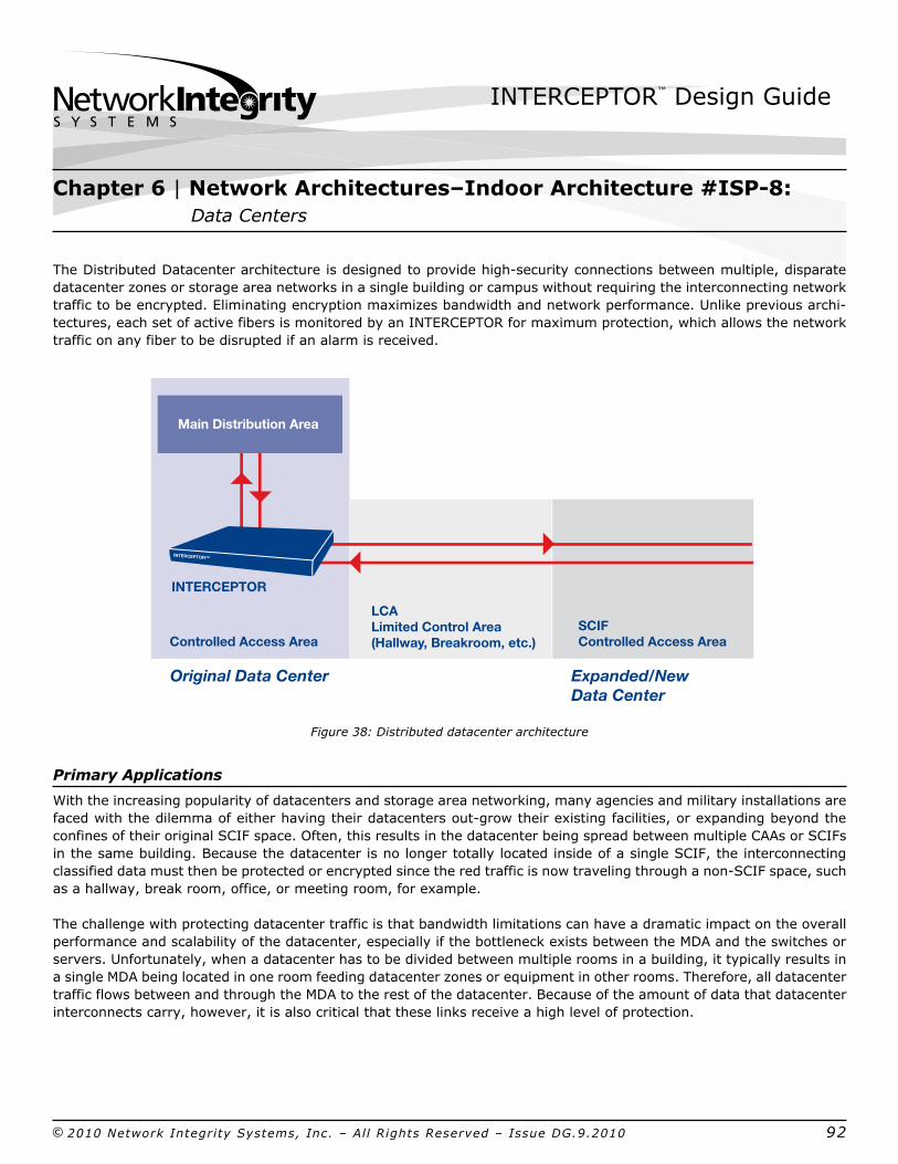
INTERCEPTOR™ Design Guide
© 2010 Network Integrity Systems, Inc. – All Rights Reserved – Issue DG.9.2010 92
The Distributed Datacenter architecture is designed to provide highsecurity connections between multiple, disparate datacenter zones or storage area networks in a single building or campus without requiring the interconnecting network traffic to be encrypted. Eliminating encryption maximizes bandwidth and network performance. Unlike previous architectures, each set of active fibers is monitored by an INTERCEPTOR for maximum protection, which allows the network traffic on any fiber to be disrupted if an alarm is received.
Figure 38: Distributed datacenter architecture
Primary Applications
With the increasing popularity of datacenters and storage area networking, many agencies and military installations are faced with the dilemma of either having their datacenters outgrow their existing facilities, or expanding beyond the confines of their original SCIF space. Often, this results in the datacenter being spread between multiple CAAs or SCIFs in the same building. Because the datacenter is no longer totally located inside of a single SCIF, the interconnecting classified data must then be protected or encrypted since the red traffic is now traveling through a nonSCIF space, such as a hallway, break room, office, or meeting room, for example.
The challenge with protecting datacenter traffic is that bandwidth limitations can have a dramatic impact on the overall performance and scalability of the datacenter, especially if the bottleneck exists between the MDA and the switches or servers. Unfortunately, when a datacenter has to be divided between multiple rooms in a building, it typically results in a single MDA being located in one room feeding datacenter zones or equipment in other rooms. Therefore, all datacenter traffic flows between and through the MDA to the rest of the datacenter. Because of the amount of data that datacenter interconnects carry, however, it is also critical that these links receive a high level of protection.
Chapter 6 | Network Architectures–Indoor Architecture #ISP8: Data Centers
Original Data Center Expanded/New Data Center
Controlled Access Area
Main Distribution Area
INTERCEPTOR
INTERCEPTOR™
LCA Limited Control Area(Hallway, Breakroom, etc.)
SCIFControlled Access Area
INTERCEPTOR™ Design Guide
© 2010 Network Integrity Systems, Inc. – All Rights Reserved – Issue DG.9.2010 93
When it is not necessary to disrupt network traffic (i.e., not every fiber needs to be protected by an INTERCEPTOR), then the SCIF Trunk architecture can be used instead to monitor a few fibers in each of the cables linking the disparate areas of the datacenter.
Design Considerations
In this architecture, it is important to ensure that all applicable connections are adequately documented and protected. In TIA942, several datacenter architectures leverage both primary and secondary connections for redundancy. It is critical to ensure that all connections are included in INTERCEPTOR deployment planning.
The first design element to consider is the number of fibers that must be protected by the INTERCEPTOR. The easiest way to calculate this is to include all of the fibers in the cable that connects the CAAs or SCIFs. Thus, if the connection between two datacenter rooms or floors is a 144fiber cable, then there will be a need for seventytwo INTERCEPTOR ports.
By leveraging CTTA approval to use interlocking armored cable with the INTERCEPTOR, the SIPRNet/JWICS cables can be easily run below the floor or above the ceiling of the datacenter. The armored cables can be deployed using jhooks, ladder racks, or wire baskets for cable management and support.
Typically in this datacenter architecture, the SIPRNet/JWICS network cabling only traverses an LCA, but each end terminates in a SCIF; thus, padlocksecured hardened workstation enclosures are not required.
INTERCEPTOR Alarmed Carrier PDS Components/Options
Since the Distributed Datacenter architecture provides a high level of security by protecting every lit fiber, only Interceptor+Plus units can be used. A microRTU will be required for each pair of fibers protected by the Interceptor+Plus in order to minimize the number of ports required.
For example, a new datacenter expansion required a twelvefiber cable to be installed between the first floor datacenter and the third floor SAN equipment. Eight of the twelve fibers will be lit initially with four fibers available for future growth. A single, fourport INTERCEPTOR+Plus unit would meet the minimum requirements. The facility will also need four microRTUs to be deployed at the far end of the cable in the SAN area.
Scalability of INTERCEPTOR Equipment
In this architecture, one INTERCEPTOR port is used to protect a pair of fibers between disparate areas of the datacenter. Therefore, if new requirements emerge for additional fiber optic cables to be installed or for the datacenter to be expanded into new areas, an equivalent number of INTERCEPTOR ports would need to be added.
Chapter 6 | Network Architectures–Indoor Architecture #ISP8: Data Centers
INTERCEPTOR™ Design Guide
© 2010 Network Integrity Systems, Inc. – All Rights Reserved – Issue DG.9.2010 94
INTERCEPTOR Alarmed Carrier PDS Components/Options
Although this Design Guide represented each possible architecture as separate and independent from the others, it is very likely that any medium to large deployment of INTERCEPTORs will require the use of multiple architectures in order to optimize the protection provided by the INTERCEPTOR system, while at the same time reducing the cost and complexity of deployment. Essentially, all medium to large INTERCEPTOR deployments should be divided into several individual deployment scopes in order to account for differing requirements or deployment conditions. An INTERCEPTOR architecture should then be selected for each such deployment scope on its own merit and to meet its particular requirements.
Combining Architectures to Optimize INTERCEPTOR Deployment
In addition to using multiple INTERCEPTOR architectures to meet the requirements of the various deployment scope areas, you may also find it necessary to combine elements of two or more different INTERCEPTOR architectures to arrive at a novel architecture. There are potentially limitless deployment scenarios at your disposal. Rather than accounting for every such option, this Design Guide is primarily intended to increase your understanding and awareness of INTERCEPTOR architectures and deployment criteria in order to allow you to develop your own individual solution set that will work best for your particular requirements.
If you develop a new architecture, we encourage you to send an overview to Network Integrity Systems for possible inclusion in future Design Guide revisions.
Chapter 6 | Network Architectures–Indoor Architecture #ISP9: Combining Architectures to Optimize INTERCEPTOR Deployment