interactive inspection of solids: cross-sections and ...jarek/papers/capping.pdfinteractive...
TRANSCRIPT

Computer Graphics, 26, 2, July 1992
Interactive Inspection of Solids: Cross-sections and Interferences
Jarek Rossignac, Abe Megahed, Bengt-Olaf Schneiderinteractive Geometric Modeling, IBM T.J. Watson Research Center
AbstractTo reduce the cost of correcting design errors, assem-blies of mechanical parts are modeled using CAD sys-tems and verified electronically before the designs aresent to manufacturing. Shaded images are insufficient forexamining the internal structures of assemblies and fordetecting interferences. Thus, designers must rely onexpensive numerical techniques that compute geometricrepresentations of cross-sections and of intersections ofsolids. The solid-clipping approach presented here by-passes these geometric calculations and offers realtimerendering of cross-sections and interferences for solidsrepresented by their facetted boundaries. In its simplestform, the technique is supported by contemporary high-end graphics workstations. Its variations, independentlydeveloped elsewhere, have already been demonstrated.Our implementation is based on the concept of a cut-volume interactively manipulated to remove obstructingportions of the assembly and reveal its internal structure.For clarity, faces of the cut-volume which intersect a sin-gle solid are hatched and shaded with the color of thatsolid. Interference areas between two or more solids arehighlighted. Furthermore, to help users find the first oc-currence of an interference along a search direction, wehave developed an adaptive subdivision search basedon a projective approach which guarantees a sufficientcondition for object disjointness. The additional perform-ance cost for solid-clipping and interference highlightingis comparable to the standard rendering cost. An efficientimplementation of the disjointness test requires a minorextension of the graphics functions currently supportedon commercial hardware.
CR Categories and Subject Descriptions:1.3.3 [Computer Graphics]: Picture/ImageGeneration -Display Algorithms; 1.3.5 [ComputationalGeometry and Object Modeling]: Solid Representation;1.3.7 [Three-Dimensional Graphics and Realism]: VisibleSurface Algorithms; J.6 [Computer Aided Engineering]:Computer Aided Design.
Keywords: Cross-section, Clipping, Interferences.
Authors’ address:IBM Research, P.O. Box 704, Yorktown Heights, NY 10598.Rossignac: [email protected], 914-784-7630.Schneider: [email protected], 914-784-6002.
Permkon 10 ~~,py wthout fee all or part of this material is granted
provided rhar the copes arc not made or distributed for direct
commcrc~al adbantagc. the ACM copyright notice and the title of the
puhllcation and II\ date qxnr. and notice i\ given tha copying is by
pcrm~hhmn (11 Ihc ,Aw>cutlon tiw C’omputmg Machmcry. To copy
othcrwiw. or III repuhlkh. reqmre\ a kc and/or qw5tic permission.
( I’)‘)? ~ZcM-0-X’)7’)1-~7Y-l~Y~~~M)7/03s~ $01.50
1. IntroductionDesign errors discovered at the manufacturing or as-sembly stages result in expensive engineering changesand production delays. Manufacturers of mechanicalgoods have invested in advanced graphics hardware andin the solid modeling technology hoping that they willeliminate the need for clay models and drastically reducethe number of design errors prior to fabrication. Althoughdesigners can interactively visualize subsets of an as-sembly using shaded or wireframe pictures, they needcross-sections and interference highlights to understandhow components fit together in tight assemblies. Forexample, the shaded image of the small assembly inFigure 1 may be produced in realtime on most high-endgraphics workstations, but reveals neither the internalstructures of the assembly nor the interferences betweenits components.
Figure 1. A small mechanical assembly: The interference be-fween the cylinder end the connecting rod is not apparent.
The availability of an informationally complete solidmodeling representation of each assembly componentpermits the automatic calculation of cross-sections andthe calculation of interferences. Unfortunately, classicalimplementations of these functions rely on expensivegeometric operations, which, when applied to models ofindustrial complexity, increase the system’s responsetime far beyond tolerable limits for interactive sessions,
This paper describes new techniques for automatically:(1) filling and shading multi-facetted cross-sectionsthrough solids, (2) identifying and hlghlighting areas ofinterference In a cross-section, and (3) posltloning cross-sectioning planes at the beginning of interference orcontact regions.
353

SIGGRAPH ‘92 Chicago, July 26-31, 1992
The solid-clipping techniques presented here exploit ex-isting graphics architectures in novel ways to create, inrealtime, shaded images showing cross-sections, cut-outs, and interference regions. Cut-outs are discussed inSection 2. Interferences are addressed in Section 3. Theresult of a combination of these techniques is illustratedin Figure 2, where a portion of the assembly was cut awayusing a user-specified cut-volume and where the inter-ference region between the two components was high-lighted in red. Furthermore, the cross-section areas arehatched for clarity and the cut-away portions are indi-cated using transparent faces and silhouette lines.
Figure 2. Graphics inspection techniques: A mu/t/-facet cut-volume Is removed to show the internal structure of the assem-bly. The resulting cross-sections are displayed in the appropriateco/or and hatched. Red areas indicate interferences.
These techniques are based on clipping planes and onauxiliary bit-planes that are manipulated during thestandard surface scan-conversion to create and later ex-ploit appropriate pixel-masks. They exhibit realtime per-formance for simple assembly models.
A solution similar to ours for cross-section filling and in-terference highlights has been independently developedat Silicon Graphics Inc. by Kurt Akeley in 1991 [l]. It isdiscussed in Section 3.1. Hewlett Packard’s graphics li-brary also offers filling and interference highlights, butno description of the underlying techniques is available.Since the manual mentions “the collection of cappingedge data” and “cap polygons” [S], we conjecture thatan approach different from ours is used.
The automatic detection of interferences is described inSection 3.2. Its requires feedback from the graphicshardware to the application. An efficient implementationof this feedback loop is not supported on commerciallyavailable workstations; thus we simulate it by a softwareinspection of the frame buffer.
2. Solid-clippingThis section describes a new technique for computing inrealtime images of solids, or of assemblies of solids, fromwhich user-controlled linear half-spaces or polyhedralcut-volumes have been subtracted. The technique lever-a
35%es on the recent support of auxiliary clipping planes
and pixel-masks in the rendering pipeline of high-endgraphics workstations [13].
Clipping planes are commonly used for surface-clipping,i.e. to trim the objects’ faces prior to display. The differ-ence between the solid-clipping technique presented inthis section and the previously available surface-clippingis illustrated in Figures 3 and 4 using a single-face cut-volume, i.e. a volume bounded by a single clipping plane.Figure 3 shows the effect of the standard surface-clipping,which treats each solid as a hollow shell, because clip-ping planes do not fill pixels, but merely limit the extentof faces. The image is confusing, since the viewer mustmentally reconstruct the areas where the clipping planeintersects the solids. Figure 4 shows the result of the newsolid-clipping technique, which, in addition to clipping thesolids’ faces, also fills the regions of intersection betweeneach solid and the clipping plane. These cross-sectionregions are hatched to visually differentiate them fromother surfaces in the assembly.
Figure 3. Surfacecllpping: The standard surface-clipping tech-nique correctly removes portions of the solids’ faces, but doesnot fill in the cross-section areas.
Figure 4. Solid-clipping: In addition to the surface clipping ofFigure 3, the cross-section of each solid by the clipping plane ishatched and shaded using the color of the solid.
Computer Graphics, 26, 2, July 1992
A standard way to produce the image of Figure 4 is to
perform the Boolean difference operation between the
solids and the cut-volume and to display the result. A
slightly better approach combines surface clipping with
the display of a cross-sections computed as the geomet-
ric intersection of the solid with a plane [7]. A CSG for-
mulation of the result may also be us&d with
special-purpose direct CSG rendering hardware
[3-5, 11],
The technique described in this section provides an al-
ternative which neither requires the hardware used for
efficiently rendering CSG models nor any complex ge-
ometric intersection calculations. It works with any
boundary representation for solids, provided that the
scan-conversion method used by the graphics hardwaresatisfies the following parity condition,
Men the entire solid fits between the front and the backclipping planes, each pixel is visited an even number of
times during the scan-conversion of the soiid’s faces.
Eariy scan-conversion techniques did not guarantee the
parity condition at pixeis traversed by the projection of
a common edge between two faces, A reiiable imple-
mentation of the methods presented here requires a
“true point-sampiing” scan-conversion [9].
To estabiish which points of a clipping plane lie inside any
given soiidl we use the foiiowing property [14].
A point Q iies inside a bounded soiid S if and only if Q is
not on the boundary of S and if a semi-infinite iine (ray)
starting at Q intersects the boundary of S at an odd
number of isoiated transversal intersection pointsl. Since
the resuit is independent of the direction for the ray, the
viewing direction may be used. Suppose that the location
of (2 is stored in the z-buffer as Z(q), the depth of the pixel
q corresponding to the projection of Q onto the screen.
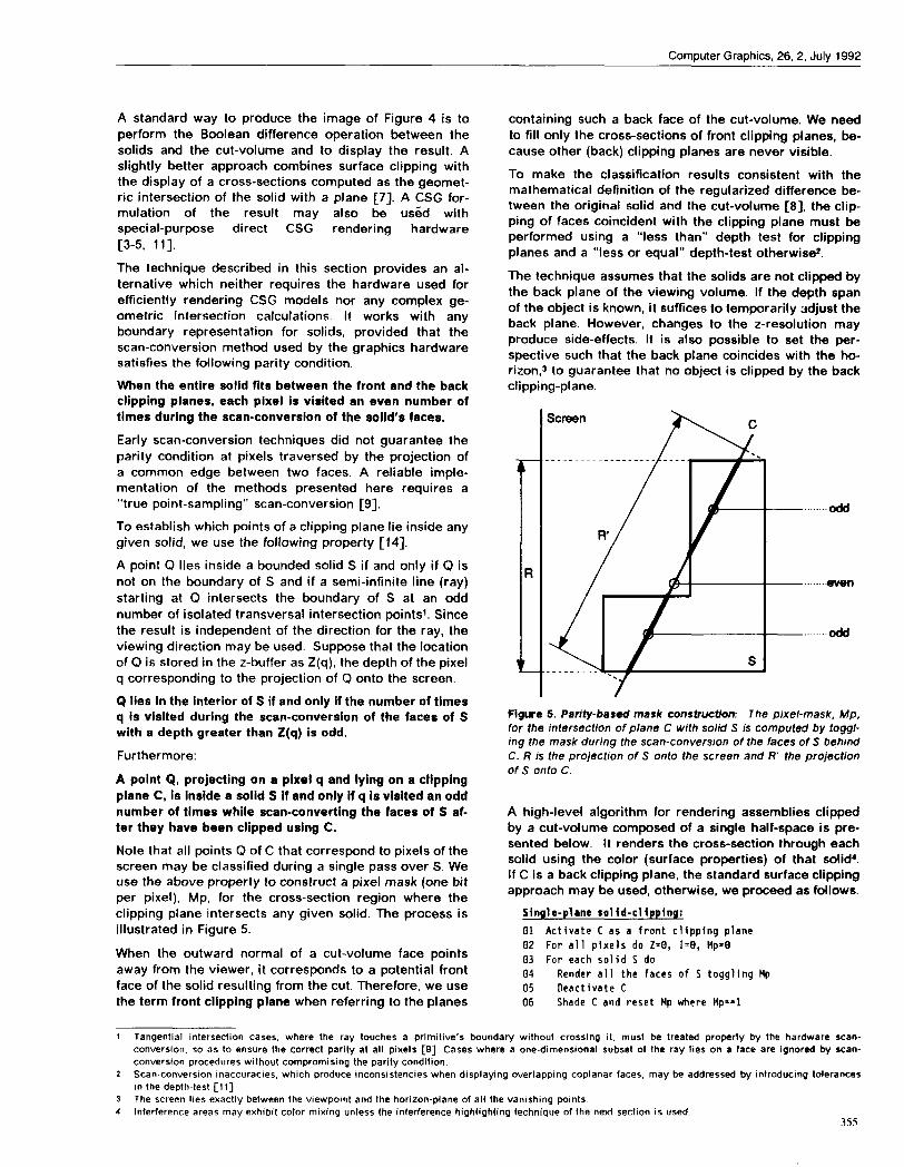
Q Iiea in the interior of S if and oniy if the number of times
q is visited during the scan-conversion of the faces of S
with a depth greater than Z(q) is odd.
Furthermore:
A point Q, projecting on a pixel q and lying on a clipping
plane C, ia inside a solid S if and only if q ia visited an odd
number of times whiie scan-converting the faces of S af-
ter they have been ciipped using C.
Note that aii points Q of C that correspond to pixels of the
screen may be classified during a singie pass over S, Weuse the above property to construct a pixel mask (one bit
per pixel), Mp, for the cross-section region where the
clipping piane intersects any given soiid. The process is
illustrated in Figure 5.
When the outward normai of a cut-volume face points
away from the viewer, it corresponds to a potential front
face of the soiid resulting from the cut. Therefore, we use
the term front clipping plane when referring to the pianes
containing such a back face of the cut-voiume. We need
to fiil oniy the cross-sections of front ciipping pianes, be-
cause other (back) ciipping pianes are never visibie.
To make the classification results consistent with the
mathematical definition of the regularized difference be-tween the originai soiid and the cut-voiume [8], the clip-
ping of faces coincident with the ciipping plane must be
performed using a “iess than” depth test for clippingpianes and a “less or equai” depth-test otherwise.
The technique assumes that the soiids are not clipped by
the back piane of the viewing volume. if the depth span
of the object is known, it suffices to temporarily adjust the
back plane. However, changes to the z-resolution may
produce side-effects. It is also possible to set the per-
spective such that the back plane coincides with the ho-
rizon,s to guarantee that no object is ciipped by the backclipping-piane.
Semen Ac
. . . . . . . . . . . . . . . ..-
—.. odd
—- ......even
—.. odd
Figure 5. Parity-based mask construction: The pixel-mask, Mp,for the iritersectlon of plane C with so/id S /s computed by togg/-irrg the mask durhrg the scan-conversion of the faces of S behhrdC. R Is the projection of S onto the screen and R“ the projectionof S onto C.
A high-levei algorithm for rendering assemblies ciipped
by a cut-volume composed of a single half-space is pre-
sented below. It renders the cross-section through each
soiid using the coior (surface properties) of that solid4.if C is a back clipping piane, the standard surface clipping
approach may be used, otherwise, we proceed as foiiows.
Single-plane sol id-cl ipping:
01020304es06
Activate C as a front clipping planeFor all pixels do Z=Et, 1=0, Mp=OFor each solid S do
Render all the faces of S toggling MpDeactivate CShade C and reset Mpwhere t4p==l
1 Tangential intersection cases, where the ray touches a primitive’s boundary wlthoul crossing it, must be treated properly by the hardware scan-converslon, so as to ensure the correct panty at all pixels [9] Cases where a one-dimensional subset or the ray lies on a face are ignored by scan-conversion procedures without compromising the parity condition
2 Scan-conversion inaccuracies, which produce inconsistencies when displaying overlapping coplanar faces, may be addressad by Introducing tolerances
in the depth-test [11]
3 The screen lies exactly between the viewpo)nt and the horizon-plane of all the vanishing peints
4 Interference areas may exhibit color mixing unless the interference highlighting technique of the next section is used355

SIGGRAPH ‘92 Chicago, July 26-31, 1992
Line 02 resets the z-buffer (Z), the frame buffer (I), andthe pixel mask (Mp). During the rendering of the facesof S (Line 04). the portions cut away by C or by the clip-ping planes of the viewing volume are discarded. Theremaining portions are scan-converted and for each sur-face point s projecting on some pixel q, the following op-erations are performed: (1) toggle the parity mask Mp(q),(2) if the depth of s is smaller than the depth stored atq, update the z-buffer and the frame buffer at q. Note thatboth the front and the back faces of S must be scan-converted for the mask computation, although only thefront faces need to be rendered.
The cross-section filling of Line 06 is performed using thecolor and surface properties of S, to distinguish the con-tribution of each solid to the cross-section. C is deacti-vated (Line 05) to prevent self-clipping.
The standard depth-test for hidden surface removal isused during the rendering of the faces of S (Line 04) andof the cross-section C (Line 06) to ensure that only visiblefaces in a scene are rendered. Consequently, convexcut-volumes may be produced using several passesthrough this algorithm for different clipping planes.
To render the cross-section using the standard scan-conversion with hidden-surface removal, a suitable faceFc on C must be constructed. As the clipping plane ismanipulated interactively, Fc must be adjusted to alwayscontain the cross-section area. We use a rectangle in Cenclosing the orthogonal projection, R’, of S onto C (Fig-ure 5).
Polyhedral cut-volumes with concave edges defined asarbitrary Boolean combinations of half-spaces may beneeded to better expose the internal structure of tightassemblies. An example is shown Figure 6. The remain-der of this section presents an extension of the solid-clipping technique for such cut-volumes.
Figure 8. Sol/d-clipping with non-convex cut-volumes: Threeclipping planes. Cl,Cp. and Cs, are used to define a compoundcut-volume, Cl n (C2 u (23).
Although, the metaphor of a “cut-volume”, v, interac-tively manipulated by the designer to remove obstructing
An efficient implementation of the solid-clipping withcomposite cut-volumes requires: (1) a standard z-buffer,(2) an application-controlled set of clipping planes, (3) onebit-plane for the mask, and (4) facilities for programmingthe scan-conversion so as to toggle the bit-plane for eachsurface point and to use the mask as a condition for ren-dering. All these facilities are supported by commerciallyavailable graphics hardware for a limited number ofapplication-controlled clipping planes.
5 The dlsiunctivelorm is a union of products, each product wing me inlersecllon of half-spaces.
356
portions of the assembly may be more intuitive than thenotion of a “clipping volume”, v’, used to delimit the as-sembly through an intersection operation, both formu-lations are equivalent, since v’ is the complement, V, ofv, and for any solid S, we have: S - v = S n v’.
Given a Boolean expression of v, it is straightforward toextract a disjunctive forms for v’. For example, if the lin-ear half-space volumes are denoted Vi, the cut-volumev = (vj U ~2) rl (~3 U v,) yields the following disjunctiveform of two products: fl n a u 6 n 3 for v’.
The intersections of S with these convex clipping-products are processed one-by-one using the algorithmbelow. The image of the union of these intersections iscomposed via the standard z-buffer test.
Solid-clipping algorithm for (I clipping-product:01 For all pixels do Z=D, IsO, Hp-1302 For each solid S do03 For each clipping-product P do04 Activate all the front clipping planes of P05 Disable writing into the depth and frame buffers06 Render all the faces of S toggling Hp07 Select rendering color for S08 Enable writing into the depth and frame buffers09 Activate all the front and back clipping planes10 Render the front faces of S11 For each front clipping plane C in P do12 Deactivate C13 Shade C and reset Hp for pixels where Hp-=l14 Activate C15 Deactivate all planes of P
In Line 06, the front and back faces of S are clippedagainst all the front clipping planes of a product and thenscan-converted. Each time a pixel q is visited during thatscan-conversion, its mask bit Mp(q) is toggled. The frameand z-buffers are never updated during that scan-conversion (see Line 05). After the execution of tine 06,the mask Mp corresponds to a cut-volume composed ofonly the front cutting planes of that product (see Figure7). When the cross-sections are displayed for that prod-uct (Line 13), this mask is used in conjunction with theother front and back clipping planes to delimit the con-tribution of each front clipping plane.
Each front clipping plane is temporarily deactivated (tine12) prior to display (Line 13) to avoid self-clipping. Theportions of the front faces of S that lie within theclipping-product and are not hidden by previously ren-dered objects are rendered into the z-buffer and theframe buffer (Line 10). The rendering in Line 13 is per-formed using the standard z-buffer test.

Computer Graphics, 26, 2, July 1992
I screen /
performance on an affordable platform has not been
demonstrated. Boxing techniques provide only a neces-
1 r’ /sary condition for interference. Consequently, the ap-proach described in this section constitutes an important
W-~A.———
sMp
——— — ——
cross-emotion
tool for detecting and displaying interferences. The firstportion of this section focuses on an extension of thesolid-clipping technique to highlight interferences in thecross-sections (Figure 9). The second portion presents a
technique for automatically locating the beginning of in-
terference regions along a user-specified search direc-
tion. This search facility is used interactively for two
purposes: (1) to quickly and reliably establish that a par-
.~ B titular region is free of interferences or (2) to automat-
Figure 7. A4asking for a clipping-product Two front clippingplanes A and B and one back clipping plane C bound ac/ipping-producL L4p is constructed by scan-converting S c/ippedby A and B. The visible cross-sections are obtained by renderingA (clipped to B and C) and B (clipped to A and C) over pixelswhere Mp IS 1.
3. Interferences
Usually, a mechanical assembly must be free from inter-
ferences, but may contain lower-dimensional contact re-
gions z between its components.
Intersections between pairs of solids may be computed
in various ways. A geometric approach evaluates the
boundary of the regularized Boolean intersection of the
two solids. The existence of a single vertex in the inter-
section suffices to indicate interference. Efficient Null
Object Detection techniques may be used, especially ifthe solids are in CSG form [1 O, 15]. Hardware architec-
tures for testing interferences between triangulated
boundaries have also been proposed [16]. Although
asymptotically efficient computational geometry tech-
niques for finding the minimum distance between twopolyhedra are available [2], these numeric approaches
are too expensive for interactive inspection and should
be reserved for the final stages of the assembly verifica-
tion.
Two hardware-assisted graphics techniques are relevant
to interference detection: (1) a discretized (ray casting)
approach reduces interference detection to a series of
one-dimensional interval-intersection tests and is sup-
ported by special-purpose ray-casting hardware [3] and
(2) the ability to automatically select and report which of
the scan-converted objects interfere with an application-
defined block provides a mechanism for eliminating un-
necessary interference calculations. (Solids that are
clearly disjoint from any solid S because they are disjoint
from a box containing S may be efficiently identified that
way. )
Geometric intersection techniques are too expensive.
Ray-casting can be efficiently parallelized, but interactive
ically loc~te the first interference region a’nd position the
clipping plane at its beginning to facilitate the visual in-
spection of the extent of the interference. Subsequent
interferences are located automatically by starting the
search past the current interference region.
3,1 HighiighCing interference areas
The algorithm for highlighting the interference is pre-
sented below in its simplified version for a clippingproduct restricted to a single front ciipping piane C. The
successive steps are illustrated in Figure 8, The aigorithm
computes a parity pixel mask, Mp, for the cross-section
of the current soiid, a cumulative (union) pixel mask, Mu,
for the union of the cross-sections of all previously proc-
essed solids, and an intersection-mask, Mi, The cross-
section of the solid, restricted to (Mp AND NOT Mu), is
rendered with the soiid’s colors. The interference area
is rendered at the end in a highlighted mode over Mi.
Algorithm for highl ighting interferences:
01 For all pixels do Z=O, 1=0, Mu-O, Mi=O, and Mp=O02 For each solid S do03 Activate C as a clipping plane04 Scan S toggling Mpand rendering where Mu==O05 Oisable writing into z-buffer06 Deactivate C07 Render C where Mp==l and Mu==O08 For all pixels in R do09 If (Mu==l &&Mp==l) Mi=l10 If (Np==l) Nu=l and t!p=O11 Enable writing into the z-buffer12 Oisable writing into z-buffer13 Select color and style for the interference14 Render R’ on C for pixels where Hi==l15 Enable writing into the z-buffer16 Oisable writ{ng into the frame buffer17 Render R’ on C for oixels where Mu==l
in Line 04, all the front and back faces of S are ciipped
by C and then scan-converted. For each access to a pixei
during that scan-conversion the pixei’s parity mask, Mp,
is toggied. Furthermore, if at that pixei the mask Mu is
not set, the z-buffer and frame buffer are updated. (Note
that this update is not necessary for the back faces of S. )
Testing Mu prior to update avoids overwriting previously
computed cross-sections for which the z-buffer has not
yet been properly set.
6 The interference between two solids A and B is their regularized intersection (A n*B) Regularization removes lower dimensional parts, ihus, the regu.
Iarized intersection IS the closure of the interior of the Intersection [8]
7 The contact between two solids Is ((A n B) (A n*B)), the set theoretic difference between their set theoretic Intersection and their regularized inter-
section357
SIGGRAPH ‘92 Chicago, July 26-31, 1992
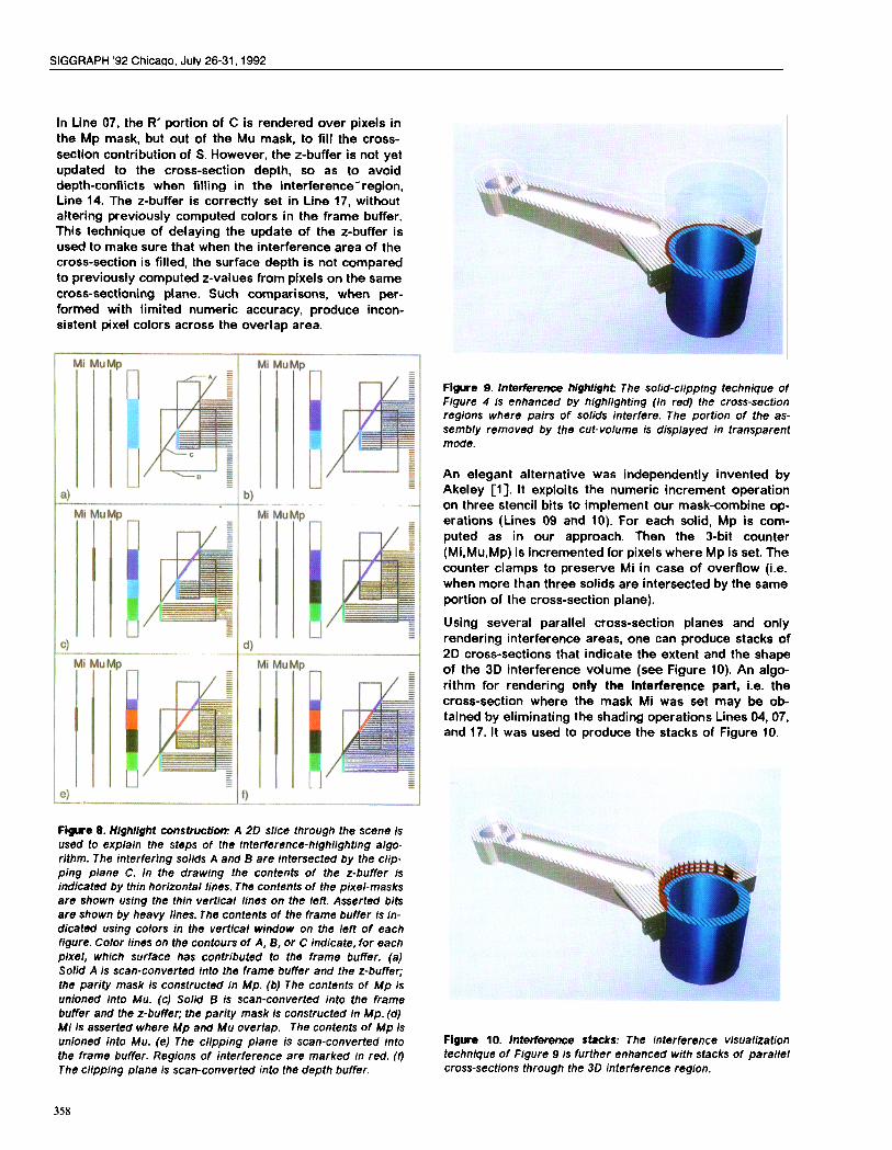
In Line 07, the R’ portion of C is rendered over pixels inthe Mp mask, but out of the Mu mask, to fill the cross-section contribution of S. However, the z-buffer is not yetupdated to the cross-section depth, so as to avoiddepth-conflicts when filling in the interference-region,Line 14. The z-buffer is correctly set in Line 17, withoutaltering previously computed colors in the frame buffer.This technique of delaying the update of the z-buffer isused to make sure that when the interference area of thecross-section is filled, the surface depth is not comparedto previously computed z-values from pixels on the samecross-sectioning plane. Such comparisons, when per-formed with limited numeric accuracy, produce incon-sistent pixel colors across the overlap area.
Figure 8. Highlight wnstruction: A 20 slice through the scene Isused to explain the steps of the interference-highlighting algo-rithm. The interfering solids A and B are intersected by the clip-ping plane C. In the drawing the contents of the z-buffer isindicated by thin horizontal lines. The contents of the pixel-masksare shown using the thin vertical lines on the left. Asserted bitsare shown by heavy lines. The contents of the frame buffer is in-dicated using colors in the vertical window on the /eft of eachfigure. Color lines on the contours of A. B, or C indicate, for eachpixel, which surface has contributed to the frame buffer. (a)Solid A is scan-converted into the frame buffer and the z-buffer;the parity mask is constructed in Mp. (b) The contents of Mp isunioned into Mu. (c) Solid B is scan-converted into the framebuffer and the z-buffer; the parity mask is constructed In Mp. (d)MI Is asserted where Mp and Mu overlap. The contents of Mp isunloned into Mu. (e) The cllpping plane is scan-converted intothe frame buffer. Regions of interference are marked in red. (f)The clipping plane is scan-converted into the depth buffer.
Flgure 9. interference hlghlight: The solid-dipping technique ofFtgure 4 is enhanced by highlighting (in red) the cross-sectionregions where pairs of solids interfere. The portion of the as-sembly removed by the cut-volume is d/splayed in transparentmode.
An elegant alternative was independently invented byAkeley Cl]. It exploits the numeric increment operationon three stencil bits to implement our mask-combine op-erations (Lines OS and 10). For each solid, Mp is com-puted as in our approach. Then the 3-bit counter(Mi,Mu,Mp) is incremented for pixels where Mp is set. Thecounter clamps to preserve Mi in case of overflow (i.e.when more than three solids are intersected by the sameportion of the cross-section plane).
Using several parallel cross-section planes and onlyrendering interference areas, one can produce stacks of20 cross-sections that indicate the extent and the shapeof the 3D interference volume (see Figure 10). An algo-rithm for rendering only the Interference part, i.e. thecross-section where the mask Mi was set may be ob-tained by eliminating the shading operations Lines 04, 07,and 17. It was used to produce the stacks of Figure 10.
Figue 10. Interference stacks: The Interference visualizationtechnique of Figure 9 is further enhanced with stacks of parallelcross-sections through the 30 interference region.
358

Computer Graphics, 26, 2, July 1992
3.2 Locating interference regions
This subsection is devoted to the automatic detection andlocation of interferences and contacts along a user-
defined search direction and within a given search inter-val.
Without loss of generality, the search direction is chosen
orthogonal to the cross-sectioning plane C. The search
interval is confined to a slice between C and another
plane C’ parallel to C. The location of C’ may be specified
by the user or computed automatically from a bounding
box, so as to extend past the entire assembly. The posi-
tions of C and C’ are indicated by the starting and ending
parameters Z,ati and Z,nd along the search direction D.
Using a stack of parallel cross-sections evenly distributed
between Ztian and ZOn~and testing if any of them contains
an interference region will not guarantee the detection
of interferences, since these may occur between two
consecutive cross-sections. The cost of testing a suffi-
cient number of cross-sections to reduce the size (in
depth) of possibly missed interferences is prohibitive.
Instead of such a discrete probing, the technique pre-
sented here uses the procedure “IntersectionFreeSlice”
to compute a sufficient but not necessary condition for
interference. If the answer is negative, the designer may
be reassured immediately. Otherwise, the following al-
gorithm recursively subdivides the search interval
(Ztifi, Z.~) until a user-defined maximum level (i.e. mini-
mal slice thickness), L, is reached (in which case, the
beginning of a possible interference region is returned)
or until all branches of the search tree that correspond
to positive test result have been explored (in which case
there is no interference and Z.ti is returned). The mini-mal slice thickness, the depth resolution, and the z-
scaling factors control the accuracy of the test and define
the ability to differentiate between interference and con-
tact. The command Search(Ztiati, Zon& Ml), where Ml de-
fines the maximum recursion level, starts the search.
Ml may be adjusted to ensure the desired accuracy. The
parameters, 2s, Ze, and level define the current status
of the recursion,
Algorithm for interval 1ocation:
91 Search (Zs, Ze,level)e2 If (Intersect ionFreeSl ice(Zs, Ze)) return Zend03 If (level -=L) return Zs04 Zm=(Zs+Ze)/205 Zf=Search (Zs, Zm,level+l)06 If (Zf!=Z,nd) return Zf07 Else return Search (Zm,Ze,level+l)
A 2D bounding box around the discovered interference is
used to position an arrow highlighting the potential in-
terference region. The clipping plane C is automatically
placed at the beginning of that interval, so that the user
can inspect the area, then move C past the current in-
terference, and finally resume the search.
The “IntersectionFreeSlice” test is implemented in the
following algorithm by generating a mask Mp for the
projection of the intersection of the current solid S with
the slice and by testing if this mask intersects the Mu
mask for the union of the projection of previously proc-
essed solids. The approach is based on the following
property.
If the projections of the slices through the solide are die-joint, there is no interference within the ailce.
Intersect ionFreeSl ice:
01 Activate C as a front clipping plane02 For all pixels do Mu=tl, Mi=O, 14p=003 For each solid S do04 Scan-convert S toggling Mp05 Activate C’ as a back clipping plane06 Scan-convert S forcing i4p=l07 For all pixels in R do08 If (Hu==l ~& Mp==l) return O
09 If (Hp.-l) Mu-1 and Mp=O
To avoid missing thin interferences that fall between
pixels, it suffices, as part of the shading of a solid, to draw
the edges of each solid in lines 3 pixels wide. Each edge
must be drawn twice to maintain the parity condition. (We
simply draw the edges of each face after shading it. ) On
the other hand, to distinguish contact regions from true
interferences, we apply a two-dimensionai discretized
morphological shrinking operation [12], i.e. a 3x3 filter
over ali pixels, to the mask Mi so as to remove interfer-
ences that are thinner than two pixeis.
By acting on the scaling factor (i.e. the space distance
corresponding to the inter-pixel resolution), one can ad-
just the thresholds between clearance, non-invasive
cent act, and true interference. By performing the
“lntersectionFraeSlice” test twice (once with drawing the
edges and once with eroding the mask) one can distin-
guish ciearance (if both test return false), from contacts
(if the results of imth tests are different), from interfer-
ences (if both tests return true). However, searching trueinterferences (through mask erosion) for regions with
oblique contact areas between overlapping faces of dif-ferent objects forces the adaptive subdivision to visit all
the branches of the search tree down to a depth corre-
sponding to a slice thickness for which there is no inter-ference between the projections of the solids.
The interference search automatically positions the
cross-sectioning plane at the beginning of an interference
region. The user examines the interference by moving
the viewpoint and the clipping piane. The interfering ob-
jects may be selected by a graphic pick and the corre-
sponding CAD modeis which require engineering changes
may be identified. Facilities for interactively hiding some
models or for producing exploded views also help decide
which of the interfering parts must be redesigned.
The search algorithms described above require exten-
sions to the functions supported by currently available
graphics iibraries and may also involve some hardware
modifications. For example, Line 08 of the
“lntersectionFreeSlice” algorithm requires a feedback
from the buffer to the application. Such a feedback exists
for reporting enclosing boxes around pixels traversed by
the scan-conversion, but does not take into account any
result of testing mask values for these pixels. This step
is handled trxfay by the application software which must
inspect each pixel of Mi. Similarly, the erosion operation
is also currently performed in software, which consider-
ably reduces the performance of the search algorithm.
359
SIGGRAPH ’92 Chicago, July 26-31, 1992
Nevertheless, except for regions where two or more ob-
jects are in contact, the search algorithm only visits a few
branches of the search tree, and thus its software imple-
mentation requires the inspection of only a small number
of pixel-masks within a limited domain (R).
ConclusionSimple algorithms for displaying cross-sections through
solids, for highlighting interference areas, and for auto-
matically detecting interferences and contacts between
solids have been presented. Because the additional cost
for filling the cross-sections and for highlighting interfer-
ence areas does not significantly exceed the original
rendering cost, these algorithms exhibit realtime per-
formance for small assemblies–with the exception of in-
terference detection. They provide the engineering
visualization techniques needed to replace the expensive
c1ay models, traditionally used during the design-
inspection phases, by electronic “virtual” solid models.The algorithms have been integrated in an experimental
system developed by the Interactive Geometric Modeling
group at IBM Research and have been successfully
tested on industrial assembly models.
AcknowledgementsWe are very grateful to Kurt Akeley for his comments on
this paper and for allowing us to compare both his and
our implementations. We also wish to thank Dan
Brokenshire for pointing out the limitations of the stand-ard clipping technique for solid modeling applications and
for participating in the early phases of this work.
References[1] Kurt Akeley, Silicon Graphics Inc.. Private communi-
cation subsequent to the SIGGRAPH review process.
March 1992.
[2] David Dobkin and Herbert Edelsbrunner, Space
Searching for Intersecting Objects. ACM & IEEE Sum. on
Foundations of Computer Science, IEEE Computer Society
Press, New York, NY, 387-392, 1984.
[3] John Ellis, Gershon Kedem, Rich Marisa, Jay Menon,
and Herbert Voelcker, Breaking Barriers in Solid Model-
ing. Cl ME, pages 28-34, February 1991.
[4] Dave Epstein, Friderik Jansen, and Jarek Rossignac,
Z-buffer Rendering from CSG: The Trickle Algorithm. Re-
search Report, RC 15182, IBM T.J. Watson Research
Center, Yorktown Heights, NY, December 1990.
[5] Jack Goldfeather, Steve Molnar, Greg Turk, and
Henry Fuchs, Near Real-Time CSG Rendering Using Tree
Normalization and Geometric Pruning. IEEE Computer
Graphics and Applications, 9(3):20-28, May 1989.
[6] Starbase Reference Manual. “set_capping_planes”
command. Hewlett Packard.
[7] Martti M~ntylli, An Introduction to Solid Modeling.
Computer Science Press, Rockville, Maryland, 1988.
[8] Aristides Requicha and Robert Tilove, Mathematical
Foundations of Constructive Solid Geometry: General
Topology of Regular Closed Sets. Production Automation
Project, Tech. Memo. No. 27a, Univ. of Rochester, June
1978.
[9] Jarek Rossignac, Accurate scanconversion of trian-
gulated surfaces, in A. Kaufman, editor, Advances in
Computer Graphics Hardware Vl, Springer-Verlag, Berlin,1992.
[10] Jarek Rossignac and Herbert Voelcker, Active Zones
in CSG for Accelerating Boundary Evaluation, Redun-
dancy Elimination, Interference Detection and Shading
Algorithms. ACM Transactions on Graphics, 8(1)51-87,
January 1989.
[11] Jarek Rossignac and Jeffey Wu, Correct Shading ofRegularized CSG Solids Using a Depth-interval Buffer.
Eurographics Workshop on Graphics Hardware,Lausanne, Switzerland, September 1990.
[12] Jean Serra, Image Analysis and Mathematical
Morphology. Academic Press, New York, 1982.
[13] Graphics Library-Reference Manual, Iris 4D VGX.
Silicon Graphics, Inc., 1990.
[14] Robert Tilove, Line/Polygon Classification: A Study
of the Complexity of Geometric Computation. IEEE Com-
puter Graphics and Applications, 1(2):75-88, April 1981.
[15] Robert Tilove, A Null Object Detection Algorithm for
Constructive Solid Geometry. Comm. ACM, 27(7):684-694,
July 1984.
[16] Fujio Yamaguchi, A unified approach to interference
problems using a triangle processor. Proceedings
SIGGRAPH’85, 19(3):141-149, 1985.
36a