interactive graphics - defense technical information center · tty card linc dsly 14 31 card linc...
TRANSCRIPT
INTERACTIVE GRAPHICSA TOOL FOR APPLIED HUMAN FACTORS ENGINEERING
gel ___________
Doe0o
'T~l4
sc~/
LaUS ARMY HUMAN ENGINEERING LABORATORYABERDEEN PROVINGGROUND, MARYLAND 21005
Apoved for pubilce tw"; 82 04 09 036ditrbutlon unlimited.

INTERACTIVE GRAPHICS -A TOOL FORAPPLIED HUMAN FACTORS ENGINEERING
INTRODUCTION
The Human Engineering Applications Directorate (HEAD) is one of three directorates in theUS Army Human Engineering Laboratory (HEL). The HEAD is currently composed of fourteams with specific expertise in aviation, missile, communication, armor, tactical data, weapons,automotive systems, and display and control. Additional expertise is provided in the areas of:
1. Computer graphics and programming
2. Electronic design and development
3. Experimental design and statistical analysis
4. Vision and illumination
The teams serve as human factors engineering consultants to various DARCOM ProjectManagers. A yearly support contract (scope of work) is agreed upon between the directorate andthe project manager being supported with specific tasks delineated for completion during theyear. Important results, including design recommendations, potential problem areas, trade-offsand test results are provided to the project manager.
The Applied Research Team has primary responsibility within HEAD for command/controldisplay systems. The mission of the team is to conduct applied research studies in the area ofadvanced display technology for the purpose of defining human factors display criteria duringconceptual and validation phases of the materiel development process. Additional functionsinclude providing experimental design expertise and display research support to other HEADteams.
The organization of the Applied Research Team is shown below:
TEAM LEADER
ENGR PSYCHOLOGIST
II 1

In line with its mission, the Applied Research Team has assembled a versatile display systemdedicated to the study of human factors engineering problems involving dynamic real-timedisplay presentations found in military equipment. Our experience ranges from hand-held digitalmessage panels to anti-ballistic air-defense radar display consoles and encompasses low light levelor infrared sensor terrain images for Army aircraft.
Human factors tests are supported by the Applied Research Team to develop equipmentdesign recommendations, determine potential problem -areas and identify basic problems relatedto visual information transfer.
COMMAND/CONTROL SIMULATOR HARDWARE
The hardware facilities of the HEL Command/Control Simulator have been evolving sincethe basic calligraphic display system was installed in 1969. A Varian 620f-100 computer andassociated CDS 114 disk drive provide the digital control and storage for the simulator system.The digital system is interfaced to an IDIIOM calligraphic display system, an ISI raster scanimaging system, an Owens-Illinois plasma panel and a Singer Helicopter Operational Trainer(HOT). Emphasis has been placed on flexible real-time interactive display and control capability inthe selection of equipment. Incremental hardware additions are made with a view of maintainingsoftware compatibility, thus allowing maximum versatility with a minimum of staff.
DIGITAL SYSTEMS
A general purpose Varian 620f-100 digital computer serves as host computer for thesimulator system. The computer processes 16-bit words and has a memory cycle time of 750nanoseconds. A maximum of 32k words of core is available. Fixed-point hardwareaddition/subtraction requires 1.5 microseconds. There is no floating-point hardware. Thefollowing optional features have been provided.
a. Real-time clock
b. Priority interrupt module (PIM)
c. Priority memory access (PMA) 1'2LS
d. Analog input module irO fo'
e. Direct memory access (DMA)
4tt
INSPECTED
22 ,.

Computer peripherals consist of a card reader, COI LINC tapes, Varian Statos 31printer/plotter, electronic alphanumeric keyboard, KSR-35 teletype, and a 29 million byteCDS114 disk system.
The disk drive uses a removable eleven-high disk pack as a storage medium to provide 20usable recording surfaces. Average rotational latency is 12.5 milliseconds. Cylinder to cylinderseek time is 12 milliseconds. Interfacing to the Varian 620f-100 is through the priority memoryaccess option. Data transfer occurs at 150 thousand words per second.
A data conversion station, built about a Varian 620i computer with 16k words of core, hasperipherals consisting of a card reader, KSR-35 teletype, COl LINC tape and high-speed papertape reader and punch. It is planned that this system will eventually provide a data conversionfunction for the Helicopter Operational Trainer and will be connected to the Varian 620f-100 viaa DMA interface for the high-speed data transfer. A block diagram of the total system is shownbelow.
PP
DIGITAL C os STATOSTTY CARD LINC DSLY 14 31 CARD LINC TTY ALPHAN
5R5READER TAPE SYTM DIS PRIT READER TAPE KRSKYO
I offl)°°' (3Kmm
ANALOG INPUT MODULE ANALOG INPUT MODULE
LN -P[FUNCTION KEYBOARDIEVN$I- .R' LIG"TPEN,
RECEIVERS RSTR TL. .. ASTER DIIT AL CALLIGRAPIC-~1~~ SCAN
IMAGING DISPLAY DISPLAYSYTE SY STE SYSTEM -- i
L~_ ----
CNOIDITiONE Rs--- pOP~l0
LINE DRIVERSC0PROPOSED L
PP PLASMA PANELP.S. CAT.RASTER SCAN CRT
CRY OPERATIONAL
TRAINER
13

DISPLAY SYSTEMS
CALLIGRAPHIC DISPLAY SYSTEM '1The IDI IOM 1.2 display processing unit bidirectionally interfaces with the Varian 620f-1 00
digital system to interpret and convert the digital graphic commands to the analog form requiredfor the CRT displays. The display processing unit also provides the means by which the functionkeyboards and light pens send interrupts to the digital systems.
The system has four monochrome CRT's with P31 phosphor. Three of the monochromeconsoles are 21-inch diagonal tubes and the fourth is a 10-inch diagonal tube with a remotedisplay head mounted in the helicopter trainer. Color capabilities are provided by a large screenfour-color beam penetration phosphor CRT which uses a multilayer screen comprised of a greenphosphor layer, a barrier layer and a red phosphor layer. By switching the accelerating voltage,red, green, orange and yellow colors can be displayed. Full length vectors, 1024 raster units long,can be written in 50 microseconds. CRT display specifications are given in Appendix A.
RASTER SCAN DISPLAY SYSTEM
Solid surface image capability is provided by a raster scan imaging system developed byInterpretation Systems Inc. Images are presented on television monitors in black and white orcolor. This system is bidirectionally interfaced with the Varian 620f-100 digital system.
Graphic generators permit the automatic drawing of vectors, conics, plots, and characters.Composite displays are permitted by combining computer-generated images with TV camerainput. Raster scan display specifications are given in Appendix B.
PLASMA PANEL DISPLAY SYSTEM
A display medium which is neither calligraphic nor raster scan is available on both thesimulator system and the data conversion station. This display is an Owens-Illinois 8.5-inch x8.5-inch flat panel plasma display unit (DIGIVUE) featuring 262,144 addressable points. Thepanel has some of the advantages of both the refresh cathode ray tube and storage tube devices.Once elements are displayed on the screen, they need not be refreshed from any computer orother external source. Unlike storage tubes, individual display elements can be erased without theneed to erase the entire screen. Flicker-free operation results at any data density. Dynamicgraphics can be displayed, however, not to the degree that can be attained with refresh graphicssystems.
Several other highly desirable features of this unit should be noted. There is no distortionpresent at the edges of the viewing screen, the location of each illuminated point is fixed by wireintersection, thus providing a jitter-free display with excellent registration. The device is capableof providing composite pictures by utilizing its rear projection screen along withcomputer-generated graphics.
Reference 7 provides additional information on this display system. Plasma panel display
and controller specifications are given in Appendix C.
4

INTERACTIVE DEVICES
A 32-key function keyboard and light pen are available at each of the large screencalligraphic consoles. Other interactive devices are available which may be used at any displayposition. They are:
1. Electronic alphanumeric keyboard
2. Trackball cursor control
3. Displacement joystick cursor control
4. Stiff stick (isometric stick) cursor control
The electronic alphanumeric keyboard is a send-only unit which provides a full128-character code output. Unshifted characters are lower case. It may also be used in theteletype mode to act as an alternate system teletype.
The trackball cursor control consists of a 3-inch ball mechanically coupled to twobidirectionally optical shaft encoders, one encoder for the x-axis and one for the y-axis. Eachencoder output provides 1000 cycles per revolution of the ball.
The displacement joystick utilizes two pin-contact type shaft position encoders which aremechanically coupled to a stick extending 3 inches above the table surface. One encoder isprovided for the x-axis and one for the y-axis. One revolution of the shaft provides 2048 counts.However, since the stick displacement is mechanically limited, about 1024 counts are providedfor maximum stick displacement.
A third cursor control device is available at the CRT console positions. This unit is adual-axis force transducer, sometimes referred to as a stiff stick, an isometric stick or force stick.A short 1.3-inch control shaft extends above the table top. Forces applied by the operatorgenerate analog voltages which are converted to pulse rates and directional gating signals. Thepulse and gating signals are fed to 12-bit up-down counters. The figure below provides a plotof the pulse rate versus force for this cursor device.
50
40
40 .
356
30
261
20 FORCE TRANSOUCER/PJLSE SENEATOR
Is PULSE RATE OUTPUT VS FORCE
20 60 80 100 120 140 100 180 20 220 240 2o 260 $0 220 340 260 360 400 420 440PULSE RATE IPPSI
5

POWER SYSTEM
Interruptions to testing procedures caused by local AC power line disturbances have beenminimized by the installation of a 12.5 KVA motor-generator set. This unit isolates thecommand/control simulator from the effects of line transients, momentary power drop-outs,lightning strikes and voltage fluctuations. A transfer switch permits operation of the systemdirectly from the utility "clean line" whenever the motor-generator set is shut down formaintenance.
SYSTEM SOFTWARE
The HEL graphic display system operates under a disc-based operating system calledHIGHER, developed by Information Displays, Inc. HIGHER is written in a high level language(FORTRAN) and supports itself by providing for maintenance and modification using theHIGHER FORTRAN compiler. In addition, HIGHER contains a DAS assembler. Compilationconverts FORTRAN source statements to assembly language, then to machine language. Thistechnique allows imbedded assembly language code to perform operations outside the syntax ofFORTRAN.
HIGHER employs a dynamic memory management and automatic overlay technique whichallows programs larger than 32 k to be run. A resident monitor loads subroutines into memory asthey are called. If not enough memory is available, the least active subroutines are deleted untilenough space is available. Each time a subroutine is deleted, the remaining subroutines arerelocated so that all free space is in one block. Provisions are made for subroutines which mustremain permanently in memory at a particular location.
A full library of floating point, double precision, and complex arithmetic routines areprovided.
6
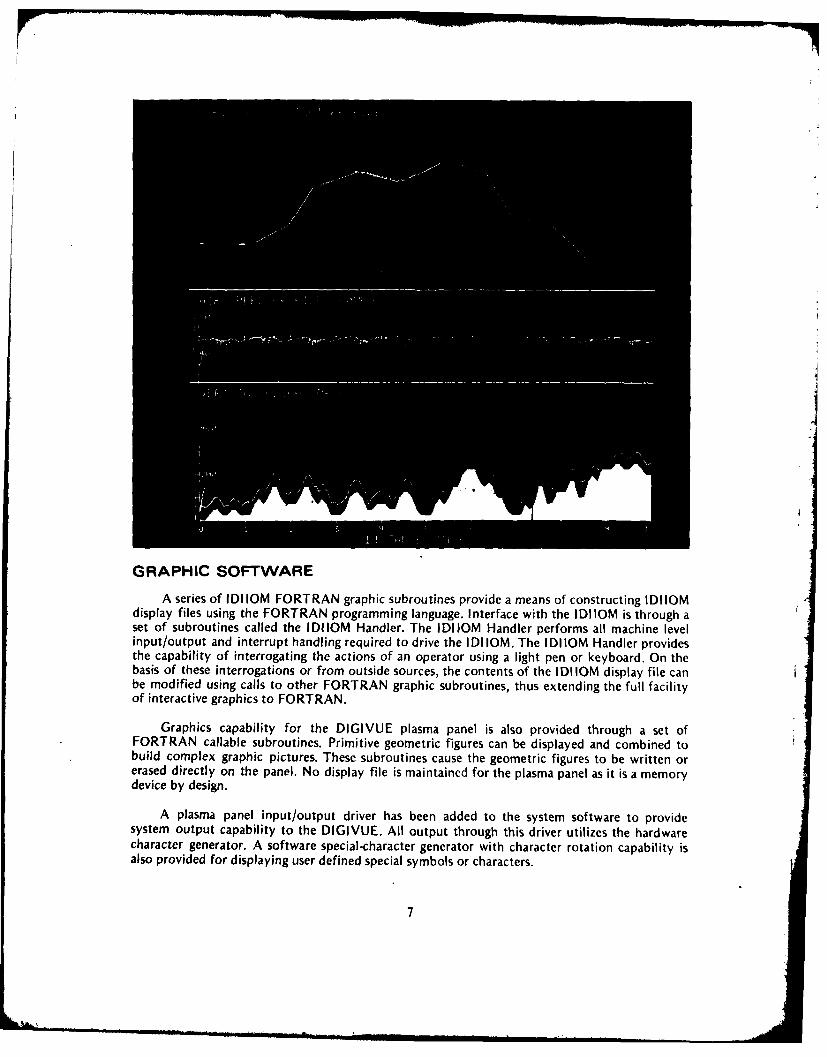
GRAPHIC SOFTWARE
A series of IDIIOM FORTRAN graphic subroutines provide a means of constructing IDI IOMdisplay files using the FORTRAN programming language. Interface with the IDIIOM is through aset of subroutines called the IDIIOM Handler. The IDIIOM Handler performs all machine levelinput/output and interrupt handling required to drive the I DI IOM. The I DIIOM Handler providesthe capability of interrogating the actions of an operator using a light pen or keyboard. On thebasis of these interrogations or from outside sources, the contents of the IDIIOM display file canbe modified using calls to other FORTRAN graphic subroutines, thus extending the full facilityof interactive graphics to FORTRAN.
Graphics capability for the DIGIVUE plasma panel is also provided through a set ofFORTRAN callable subroutines. Primitive geometric figures can be displayed and combined tobuild complex graphic pictures. These subroutines cause the geometric figures to be written orerased directly on the panel. No display file is maintained for the plasma panel as it is a memorydevice by design.
A plasma panel input/output driver has been added to the system software to providesystem output capability to the DIGIVUE. All output through this driver utilizes the hardwarecharacter generator. A software special-character generator with character rotation capability isalso provided for displaying user defined special symbols or characters.
7

APPLICATIONS
Described below are examples of human engineering studies conducted or supported by theApplied Rcsearch Team using the Command/Control Simulator.
FLIGHT INFORMATION SCALE TEST
A study was designed to assess airspeed, heading, and altitude flight status scale design foran Army helicopter heads-up display (HUD) and/or panel-mounted display.
Scales providing altitude, airspeed and heading information were combined into six flightdisplay formats which were displayed on a 21-inch monochrome CRT to a subject. The subjectinteracted with the display by using a 4-inch displacement control stick which simulated thecyclic control of a helicopter.
The subjects (qualified rotary-wing pilots) were instructed to maintain a predeterminedheading, altitude, and airspeed. Under program control, the scale readings displaced and thesubject would respond by providing the cyclic control response using the control stick. Responsetime and incorrect control motion were the dependent variables.
Results indicated that considerable leeway in scale design is permissible without causing asignificant difference in pilot performance as measured by the dependent variables. Details of thisstudy are found in reference 6.
DATA ENTRY METHODS FOR THE SB-3614/TT SWITCHBOARD
The automatic SB-3614/TT is a stored program, processor controlled, tactical switchboard.Operation of the switchboard is dependent on information stored in the memory which ismanually loaded and modified by an operator using a data entry device.
Evaluation of the contractor's method of data entry found that method was prone tocommon human errors, which, if committed, could significantly degrade the system performance.
Alternative methods of data entry were devised and a study was conducted to comparativelyevaluate the contractor's method and the alternative methods.
8

A data entry device was built and interfaced with the Varian computer and the DIGIVUEmemory display unit. A program was written to simulate the SB-3614 processor and to acceptthree methods of data entry. Subjects were tested on each of three methods of data entry:
a. Double entry (contractor's method)
b. Single entry without visual feedback
c. Single entry with visual feedback
As a result of this study, it was found that both of the single entry methods were faster andproduced less errors. Both single entry methods were preferred by the subjects, although thevisual feedback had no significant effect on -the subject's performance. Details of this study canbe found in reference 9.
EVALUATION OF TOUCH SENSITIVE KEYSET
In conjunction with the Project Manager. US Army Tactical Data Systems, a study wasundertaken to investigate the effect of two center-to-center keyspacings for 'touch sensitive' typekeysets.
Two modified keysets were fabricated having center-to-center spacing of .5 inch and .75inch. Each keyset had 12 keys, each key designated by an engraved number symbol. No audibleor tactile feedback was given when a key was pressed.
The keyset was interfaced with the Varian computer and the DIGIVUE display memoryunit and a program was written that would present a stimulus and collect and record the data. Afour-digit number was presented to the subject who would enter that number via the 'touchsensitive' keyboard. Two seconds after the subject entered the number, the next number wouldappear. The operators were tested with bare hands, wearing mittens with trigger finger, andwearing arctic mittens.
Data analysis concluded that when either mitten was used, operator performance wasdegraded considerably with the .5 inch spacing. Details of this study can be found in reference10.
9

STUDIES LEADING TO STANDARDIZATION OF RADARSYMBOLOGY III. DISCRIMINATION IN MIXED DISPLAYSCATHODE RAY TUBE PRESENTATION
The radar scope is a major source of information in air defense. Early radar displays aresimilar to oscilloscope diagnostic traces with a polar coordinate representation of the coveredarea and a time-based sweepline rotating about the antenna location. Any object struck by thetransmitted beam is seen as a 'pip' on the screen.
It later became possible to replace the raw input with synthetic video by generating ageometric form around a particular 'pip'. With geometric form, it is possible to code the obirctassociated with each return.
The HEL has been attempting to design an idealized standard code for use on radar displays.'Studies were conducted using pencil and paper drawings. After the HEL acquired the IDIIOMdisplay system, the previously described test was replicated using the CRT to display thesymbols.
The subject sees a 25-symbol page on the CRT with various coded targets scatteredthroughout the viewing area. The subject selects a target by pointing the light pen and pressingthe light-pen switch. This action draws a line through the selected symbol. When all theappropriate symbols have been selected, he calls for the next page. Errors ofomission/commission and total time are recorded for each series of symbols. The program allowsfor experimenter selection of console and geometric symbols and for random selection of symbollocations so that the tests cannot be memorized.
The test results and conclusions are lengthy and detailed and can be found in reference 4.
PATRIOT CONSOLE DISPLAY
As a natural followthrough of earlier investigations into radar symbology, the AppliedResearch Team, in conjunction with the Project Manager, PATRIOT, has been extensivelyinvolved in human engineering evaluation of the operator console for the PATRIOT (formerlySAM-D) air-defense system. The operation of this system, which is still under development,requires complex man/machine/display interactions. To properly evaluate a soldier's ability tooperate this system, a realistic simulation of the operation of the console was necessary. For thispurpose, the Applied Research Team has developed a real-time operator interactive simulation ofthe PATRIOT operator console and related activities.
Using contractor specifications, two of the IDIIOM CRT consoles were reconfigured tosimulate the physical appearance of the PATRIOT operator console. Software to emulate theoperator consolr tctivities was developed (reference 3) which had the'following characteristics:
a. Modular structure for easy software changes.
b. Real-time execution.
c. Faithful simulation of PATRIOT display and contro! processes.
d. Operator interaction via keys/stiff stick.
e. Collection and storage of performance measures.
f. Ability to present unlimited number of tactical scenarios.
1I
i ,,,bmna ,, k m ' 10..

DATA COLLECTION
DIS
00
DESIGN CRITERIAOPERATOR PERFORMANCE RESULTS
HEAD PM PATRIOT
PERFORMANCE ANALYSIS AND DESIGN RECOMMENDATIONS
11

The simulator is currently being used to assess operator performance over a variety ofconditions. Extensive data analysis programs have been written to assist in the evaluation ofoperator performance. The structure of the software has allowed HEL to test and evaluatealternate methods of information display and to locate potential human factors problems whichmight interfere with an operator's ability to perform his mission. Testing and evaluation of thissystem is expected to continue.
TANK-FIRE CONTROLRecently HEL has generated a technique for studying tracking performance by tank
gunners.
12

INTERACTIVE DATA GRAPHICS PREVIEW
Many testing programs at HEL result in the collection of vast quantities of analog datawhich may range from DC to 10 kHz. This data is often recorded on a 14-channel analoginstrumentation recorder to provide a permanent record for data analysis.
Frequently essential data, consisting of short intervals, is imbedded in many hours ofcontinuous recording. A means has been developed to obtain a quick visual analysis of largequantities of recorded analog data using the CRT. Interactive programming techniques permit theinterrogating and manipulation of the data.
o o-r 0uW Z n
The technique provides for the virtually unlimited storage of 12 channels of digitized data.Any 4 of the 12 channels can be selected for simultaneous display on the CRT. Some of thefeatures available to the user to aid in reviewing the data are:
a. Plotting the displayed data on STATOS 31 plotter/printer.
b. Scrolling data left or right (fast/slow).
c. Selecting new region for display.
d. Selecting the X/Y scaling factors.
This software has been modularized to easily accept future changes and to meet newrequirements. One of the possibilities appears to be near real-time display of multiple channelphysiological responses. Details on the use of this program are found in reference 8.
13

HELICOPTER TRAINER GRAPHICS INTERFACE
Software and hardware components are being assembled to provide for the real-timegeneration of various types of visual displays for use in the GAT helicopter trainer. Types ofdisplays include computer-generated terrain images, dynamic visual flight displays, and integratedflight instrumentation displays. Already demonstrated is the ability to generate flightinstrumentation displays, navigation displays, and radar detection warning displays using thereal-time GAT input. A versatile computer-generated dynamic flight display capability (reference1) has been successfully adapted to run on the Varian computer. This program is particularlyuseful in providing visual presentation for approach and landing procedures.
14
jf-

A development contract is in progress which will provide the capability to generate areal-time terrain image that would simulate the view from a sensor located on a helicopter inlow-altitude flight. When completed, this program will generate a real-time visual presentation ofterrain images for display on the raster scan monitor with overlaid flight instrumentationdisplays. The terrain model data base will cover a large terrain area and a variety of distinctterrain features. This program, when interfaced with the GAT helicopter trainer, will provide theability to evaluate pilot performance during nap-of-the-earth flight.
THE INFLUENCE OF SIMULTANEOUS AND SEQUENTIAL DISPLAY MODESON HUMAN INFORMATION TRANSFER BEHAVIOR
In spite of wide ranging automation, there are many situations where automation cannotreplace man as a link in data processing. One such task is manually feeding data into a computersystem. Usually, these data are not generated by the operator himself; he must acquire them fromelsewhere, either from displays, from lists, or from other information sources.
This research experiment studied the transfer tasks, input strategies and transfer behaviorinvolved in reading data that are presented, and then, without processing them, immediatelykeying the data into the computer. This transfer process usually demands both speed andaccuracy, so the criteria for evaluating performance was entry time and errors.
The I DI IOM display system with a specially interfaced subject-response keyboard was usedfor this study. Subjects read test numbers from a cathode-ray tube and entered them into thekeyboard. The numbers appeared either one digit after another (sequentially) or all digits at once(simultaneously). There were three number-lengths (four, six, and eight digits) and threeexposure times (100, 500, and 1000 msec.).
The study concluded that simultaneous displays transferred digits more effectively thansequential ones. Performance was better with shorter numbers or longer exposure times. Subjectscould transfer only four to five digits accurately and only when the exposure time was 500msec. or longer. Additional details can be found in reference 2.
15"

REFERENCES
1. Artwick, B. A. A versatile computer-generated dynamic flight display. University of Illinoisat Urbana-Champaign, Aviation Research Laboratory, TR ARL-76-5/ONR-76-1,1976.
2. Behr, E. The influence of simultaneous and sequential display modes on humaninformation-transfer behavior. Technical Memorandum 18-74, US Army Human EngineeringLaboratory, Aberdeen Proving Ground, MD, 1974.
3. Camden, R. S. Real-time air defense radar display: Operator console simulation. TechnicalMemorandum 23-76, US Army Human Engineering Laboratory, Aberdeen Proving Ground,MD, 1976.
4. Davis, C. J. Radar symbology studies leading to standardization: II. Discrimination in mixeddisplays. Technical Memorandum 5-69, US Army Human Engineering Laboratory, AberdeenProving Ground, MD, 1969.
5. Davis, C. J. Studies leading to standardization of radar symbology: Ill. Discrimination inmixed displays, cathode ray tube presentation. Technical Memorandum 27-71, US ArmyHuman Engineering Laboratory, Aberdeen Proving Ground, MD, 1971.
6. DeBellis, W. B. Flight information scale test for heads-up and panel-mounted displays.Technical Memorandum 22-73, US Army Human Engineering Laboratory, AberdeenProving Ground, MD, 1973.
7. Herald, G. L. DIGIVUE gas display controller for Varian 620 computers. TechnicalMemorandum 5-75, US Army Human Engineering Laboratory, Aberdeen Proving Ground,MD, 1975.
8. Herald, G. L. Interactive graphics data preview. Technical Memorandum 10-75, US ArmyHuman Engineering Laboratory, Aberdeen Proving Ground, MD, 1975.
9. Letter, DRXHE-HE, Subject: Preliminary Evaluation of the 'Touch Sensitive' Keyset. USArmy Human Engineering Laboratory, Aberdeen Proving Ground, MD, 14 May 1976.
10. McCommons, R. B., Cook, T. C., & Glumm, M. M. A comparative study of single versusdouble sequence data entry methods for use with the SB-3614/TT switchboard. TechnicalMemorandum 22-75, US Army Human Engineering Laboratory, Aberdeen Proving Ground,MD, 1975.
16
i:

APPENDIX A
CRT DISPLAY SPECIFICATIONS
Display Specifications:
Monochrome CRT's Phosphor-P31
Beam Penetration CRT Phosphor-P22 red-P22 green
Deflection Magnetic (electrostatic for characters on 21 inchmonochrome CRT's)
Resolution .015 inch spot size
Character Writing Time 10 us AVector Writing Time 50 us full screen and proportionally less for
shorter vectors
Circle Writing Time 100 ps any diameter
Position Generator Resolution 1024X by 1024Y
Functicns Blink controlLine structure-dot, dash, dot-dash, solidCharacter rotate 900 ccw4 levels intensity
17

APPENDIX B
RASTER SCAN SPECIFICATIONS
1. 512 x 640 horizontal raster scan 2:1 interlace
2. 16 levels grey scale, 1 level alphanumeric overlay
3. 4096 colors
4. Image manipulation functions
a. windowing
b. translation
c. scaling
d. zooming
e. scrolling
f. reversal rotation
5. Graphic functions
a. vectors [b. conics
c. plots
6. Characters - 7x9 font
18

APPENDIX C
DIGIVUE SPECIFICATIONS1
Individually AddressableLight points 262,144
Character capacity
with 5x7 matrix 4,335with 7x9 matrix 2,223 1
Dot spacing .0167"center to center
Vector address rate 7.5-8.5 mil.
Viewing angle 1600
Brightness 50 ft./L approximately
Contrast ratio-small area > 25:1 nominal
Light spectrum neon orange (S852A ° predominant)
Bulk erase 20 microseconds
Operating temperature range O°C to +550 C
Storage temperature range -620C to +850 C
Addressing rate
Serial 1,400 characters/sec 5x7Parallel 10,000 characters/sec 5x7
Logic level TTL
Clock Synchronous or asynchronous
Overall unit size 16.5" x 15.5" with hollow rear projection port
Panel size 12.25" x 12.25"
Active display area 8.55" x 8.55"
Il . . -. . . I I -I[I. . ... .. " "' 1 9" "

Character size
5x7- 80 x 120 mils7x9 120 x 150 mils
Power supply input requirements 105-125 VAC 60 Hz1.8 amps max
DIGIVUE CONTROLLER SPECIFICATIONS
Character size Sx7, 7x9
Modes-Point, Character 5x7 Normal,Character 7x9 Normal, Character Sx7 RotatedCharacter 7x9 Rotated
Logic - TTL
Operation - Asynchronous
Power - 5 Volt (for logic)
20
20