interactive 3d visualization to support concurrent …using the svn commands commit and update,...
TRANSCRIPT

CEAS 2015 paper no. 020 Page | 1 This work is licensed under the Creative Commons Attribution International License (CC BY). Copyright © 2015 by author(s).
Interactive 3D Visualization to Support Concurrent Engineering in the Early Space Mission Design Phase
Meenakshi Deshmukh German Aerospace Center (DLR), Simulation and Software Technology Research Scientist Lilienthalplatz 7, Braunschweig, 38108, Germany [email protected] Robin Wolff, Philipp M Fischer, Markus Flatken, Andreas Gerndt (German Aerospace Center (DLR), Simulation and Software Technology) ABSTRACT
The development of space systems involves complex interdisciplinary systems engineering. The concurrent engineering (CE) approach has been successfully applied to the early design phase of space missions. To bridge the gap between the development phases and between the different domain experts, a model based system engineering (MBSE) approach is showing promising results. To support CE and MBSE during space mission development, the German Aerospace Center (DLR) has started developing a new tool called Virtual Satellite. It offers extended software support required by CE for inter-domain communication, data exchange, dependency analysis, on the fly data analysis, data consistency while maintaining a common system model based on the MBSE approach. However, the general issues of inter-domain communication and understanding still exist and may lead to misinterpretation. To overcome this problem it is intended to take advantage of interactive 3D visualization and Virtual Reality techniques to visualize the complex system model and, thus, provide a common understanding of the system model and the intrinsic domain knowledge. Furthermore, this will promote the experts to communicate their ideas and improve the visibility of potential design issues. The paper describes the efforts taken at DLR in this direction, architecture details and advantages of adopting these techniques into space mission development from the early design phase. 1 INTRODUCTION
Planning and designing a space mission involves complex interdisciplinary systems engineering. Space mission projects are typically expensive, of long duration and require experts from various domains, such as power, communication, thermal, structure, propulsion, and payload. In order to manage the project complexity, the lifecycle of a space mission is commonly divided into seven phases, as defined by the European Cooperation for Space Standardization (ECSS) [1] and shown in Figure 1 on the left. Over the past ten years, the concurrent engineering (CE) process has been widely adopted for the phases 0/A early design activities. At the German Aerospace Center (DLR) in Bremen, the Concurrent Engineering Facility (CEF) is built up to efficiently support the CE design processes [2]. It is a specially designed room intended to enable a group of discipline experts to collaboratively develop a concept of a proposed space mission, see Figure 1 on the right side. It allows the co-located experts to discuss the various aspects face-to-face, present ideas, draw sketches and build ad hoc groups to discuss sub-topics. Discussed system-relevant information is directly captured into a centralized data base which supports global assessment of substantial properties like total mass, power consumption, and further system attributes. This approach allows the analysis of interdependencies between all disciplines. Eventually, it helps spotting conflicts or design issues early in the design phase. Induced by those findings, interactions between the experts can speed up the design phase even more. For this reason, similar facilities and CE processes are widely used e. g. at NASA, ESA and other space agencies.

CEAS 2015 paper no. 020 Page | 2 This work is licensed under the Creative Commons Attribution International License (CC BY). Copyright © 2015 by author(s).
Figure 1: The ECSS Space Mission development phases (left) and the Concurrent Engineering Facility at DLR, Bremen (right).
As described, the CEF allows all discipline experts to work closely together. However, the general issues of inter-domain communication and understanding still exist. Different domains have different means of communicating their data. For example, the expert of a payload instrument may not intuitively understand the numbers, graphs and diagrams of the thermal expert. Thus, in technical discussions, very often experts do not understand each other in detail, leading to misinterpretation or even failure to notice important constraints. In this paper, we propose to combine and utilize interactive three-dimensional (3D) visualization and Virtual Reality (VR) technologies as a tool to unify some of the different views and parameters seen by the experts from diverse disciplines in CE during early mission analysis studies and to make these more accessible. Complex data and scenarios are easier to explain and comprehend through the illustration and animation using 3D graphics. Collaborative visualization systems, such as large projection screens or interactive table displays, have the potential for enhancing the efficiency of data analysis, simplifying visual benchmarking, presentations and discussions. Additionally, the interaction methods typically provided by VR systems enable non-verbal communication, such as natural articulation of body movement and the communication of references. Thus, the inclusion of 3D data visualization along with VR technology right from early design phase, therefore, promises to be an important tool to help avoiding misinterpretation and detecting design flaws before later phases have started and changes become very expensive. 2 RELATED WORK
2.1 Virtual Satellite
The CEF itself allows all discipline experts to work closely together improving communication. However, the fragmentation of domain-specific data and tools induces issues of data exchange and maintaining data consistency. To address the problem of interdisciplinary data exchange and consistency, DLR’s department of Simulations and Software Technology in Braunschweig has been developing an Eclipse and Java based software tool called Virtual Satellite to support concurrent engineering in the CEF [3]. Virtual Satellite is a model-based system engineering tool with a consistent data model. As displayed in the center of Figure 2, each domain expert runs an instance of Virtual Satellite on their individual workstation. Domain experts can add, edit, remove or reorganize the system and subsystems level components of the space mission under study. The system data model is capable of creating a hierarchy of components like system, subsystem, component, equipment etc. Such equipment can be configured by the experts to develop an early design of the spacecraft. Each component allows attaching parameters to describe properties of the equipment such as the mass, its size or position.
CEAS 2015 paper no. 020 Page | 3 This work is licensed under the Creative Commons Attribution International License (CC BY). Copyright © 2015 by author(s).
Every expert works locally on a copy of the data model. As the red color indicates, they are only allowed to alter components if they have sufficient permissions. A common repository is created for the persistent and synchronized storage of collected design data using the version control system Subversion (SVN). Using the SVN commands Commit and Update, domain experts share and synchronize the data with each other. 2.2 Interactive Visualization
Interactive visualization has long been recognized as key to insight and understanding of complex data and models. Data visualization in a virtual and interactive environment is becoming a trend for effective cross-domain communication. It has shown significant improvement in understanding inter-domain dependencies, as it facilitates collaborative data exploration in an intuitive and interactive way. For example, immersive virtual environments have been used for interdisciplinary collaborative data exploration in scientific visualization of biosphere-atmosphere interactions and proved fundamental for the scientists to formulate hypotheses [4]. In other fields, it has been used to enable planetary geologists to conduct virtual field work in remote environments, such as Mars [5]. An interactive virtual environment is extremely useful in case of astronaut training [6] or the planning of robotic on-orbit servicing missions [7]. Furthermore, it has proved to be useful for analyzing simulation results in later design phases [8] [9]. VR technology offers user interfaces that enable natural interaction with the data. Immersive virtual environments typically offer a stereo view with a dynamic, first-person viewing perspective for the user. Thus, moving the head changes the perception of the virtual environment to the view of the new position. Additionally, immersive virtual environments can track the user’s hand or an interaction device, enabling the user to intuitively manipulate 3D objects and navigate through the virtual space. That together encourages people to consciously and subconsciously use their body in a natural way to observe and interact with the environment and objects within it. For example, people can simply point at objects with their hand instead of thinking about how to use a specific interaction device. Furthermore, immersive virtual environments can create the sensation of being in the virtual world as being in a real place. This is known as place illusion or presence [10]. The extent of experiencing presence highly depends on the extent of immersion. The higher the degree of immersion and the matching of sensorimotor contingencies of the system, the greater the degree of a feeling of presence within the virtual environment. Hence, hiding the technology, so that people can interact naturally with the simulation, significantly increases engagement, motivation, enjoyment and creativity. 3 INTERACTIVE VISUALIZATION ARCHITECTURE
3.1 Visualization in Virtual Satellite
Figure 2 further describes the architecture of the Virtual Satellite for visualizing the system model and a connection to a VR environment for interactive visualization and data manipulation. In a first step towards interactive visualization, Virtual Satellite has been extended by functionalities to visualize the spacecraft configuration internally in each instance of Virtual Satellite [11]. Figure 3 shows an example of a visualized system model in Virtual Satellite. To achieve this, the system model is converted to an XML based model describing the data that is necessary to visualize components. In terms of visualization, the description is as generic as possible, leading to a hierarchical representation of transformations and definitions of general shapes and color. Such general shapes refer to the actual equipment, e.g. a box represents an on-board computer. This visual model is interpreted further by software called the renderer. The renderer is based on the Visualization Toolkit (VTK) [12]. VTK includes a wrapper for Java which makes it easy to be integrated in Virtual Satellite. Changes to the system model are directly reflected in the visual model.

CEAS 2015 paper no. 020 Page | 4 This work is licensed under the Creative Commons Attribution International License (CC BY). Copyright © 2015 by author(s).
Concurrent Engineering Facility
Version Control System
VirSat Clients
Virtual Reality - Environment
VirSat – Power Discipline VirSat – AOCS Discipline VirSat – Thermal Discipline
VR - Client
SVN Server
Database SystemModel
VisualizationServer
VisualizationClient
SystemModel
VisualizationServer
VisualizationClient
SystemModel
VisualizationServer
VisualizationClient
Vis. Model
Vis. Model
Vis. Model
Visualization Client
SystemModel
Vis. Model
3D Visualization
3D Interaction
Powerwall
System
Thermal
Power
AOCS
...
PCDU
Battery
Heat Sink
Reation WheelTorquer
System
Thermal
Power
AOCS
...
PCDU
Battery
Heat Sink
Reation WheelTorquer
System
Thermal
Power
AOCS
...
PCDU
Battery
Heat Sink
Reation WheelTorquer
System
Thermal
Power
AOCS
...
PCDU
Battery
Heat Sink
Reation WheelTorquer
Trans
Trans
Trans
Trans
...
Box
Box
Cylinder
Geometry
Cylinder
Figure 2: Architecture of Virtual Satellite exchanging system model information within the Concurrent Engineering Facility as well as data interaction in a VR environment.
With this approach, each expert is capable to visualize the configuration on a local instance of Virtual Satellite. However, in some cases, design challenges require involving more than just one expert to resolve them. For this purpose, the XML based visualization model has been implemented as a shared scene-graph, which is based on a client / server architecture. This approach enables other clients, such as remote visualization clusters, steering large displays to connect to the server and receive a copy of the scene-graph. The server provides the scene-graph from the local data model to visual model transformation and synchronizes it with all instances of the clients.

CEAS 2015 paper no. 020 Page | 5 This work is licensed under the Creative Commons Attribution International License (CC BY). Copyright © 2015 by author(s).
Figure 3: 3D Visualization and interaction of the system model in the software Virtual Satellite.
Changes on either side are exchanged using an underlying messaging system. The messages are transferred across the network using the Transmission Control Protocol (TCP). The messages contain the changed parts of the serialized XML description of the scene-graph as byte stream. The XML part is then reintegrated and merged to the relevant part of the scene-graph on the other side. As indicated by the dashed green lines in Figure 2, visualization clients can be connected to a server of their choice. But a client can only be connected to one server at a time. Once a change in Virtual Satellite is applied to the system model, the visual model in the server is directly synchronized. Furthermore, the server directly notifies these changes to all connected clients indicated by the green arrows. In fact, this exchange of information is bi-directional; hence changing information on a client’s scene-graph is automatically forwarded to the server which sends it to all remaining clients as well. 3.2 Integrating VR Environments in CE
To extend the aforementioned architecture by an interactive VR environment, two further aspects need to be considered. First, the architecture needs to allow for a connection of such VR environment. Second, it needs capabilities to map changes on one of the clients back to the system model. The first aspect is covered by the client / server based shared scene-graph. It allows to attaching a new visualization client to one of the local visualization servers. Therefore, a client is developed that is capable of interpreting the scene-graph, and also visualize it in a VR environment. The renderer of this implementation is based on the VR Toolkit ViSTA [13]. For the second aspect, the scene-graph is monitored for changes and if changes occur, an update message is created. The relevant data from the visualization model gets serialized into a XML message and is sent through the network. On the Virtual Satellite side, this message is de-serialized. Mapping the change back to the system model is achieved by using Universal Unique Identifier (UUID). Every parameter in the system model contains such a UUID. Therefore a direct link from the changed part of the scene-graph back into the system model can be established.

CEAS 2015 paper no. 020 Page | 6 This work is licensed under the Creative Commons Attribution International License (CC BY). Copyright © 2015 by author(s).
4 USE CASE: SPACECRAFT CONFIGURATION
From the past CE studies, it has been observed that the configuration engineer is mainly responsible for the final component configuration of the spacecraft. The placement of each subsystem component, however, depends on each domain expert’s design perspective. The configuration engineer has to take into consideration individual domain expert’s view as well as interdependencies between the subsystems. E.g. for highly accurate estimation of the spacecraft position the payload engineer needs an extra GPS receiver. This receiver needs to be mounted in a way that it has a maximized field of view (FOW), to have a line of sight to a maximum of GPS satellites. Accordingly the FOV should not be blocked by equipment from any other discipline such as a star tracker. For that, collaborative and interactive discussion between the configuration engineer and other domain experts is needed to understand design concerns of each other and to come up with a feasible configuration agreed by all. To demonstrate our proposed idea of usefulness of VR in CE environment to improve collaborative system modeling, we explain now in detail how we support activities of the configuration engineer more effectively in immersive virtual environment using natural interaction techniques. We start with the desktop version of a visualization model created in Virtual Satellite shown in Figure 3. We transfer and reconstructed this model to the VR environment as described in the architecture section. The model is ready now for interactive manipulation in the immersive environment, as shown in Figure 4. Extending the visualization integrated in Virtual Satellite into a VR environment provides an opportunity to all domain experts to better understand the concerns of the configuration engineer. It supports domain experts to explain and demonstrate their point of view on the placement of a certain component. This happens by directly pointing to the locations or simply grabbing and moving the component to a new place, without the need to learn the user interface of the configuration engineer’s specialist tool. 4.1 Setup
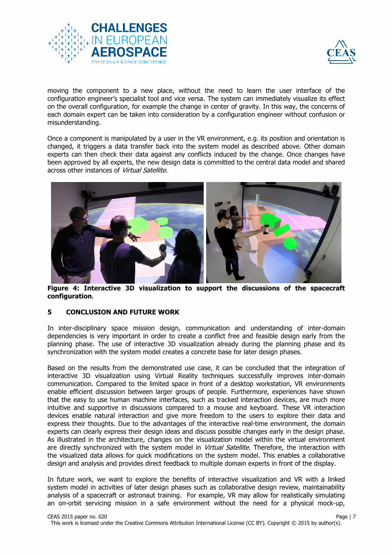
The images of Figure 4 show the realization of a virtual environment using a Powerwall. This Powerwall is based on a 3.5x2 meter rear-projection surface at the front wall and a 3.7x2 meter projection surface on the floor. It has frame-sequential stereoscopic images that are generated by 4 projectors and a PC-cluster system. Together, it provides a resolution of 2555x1400 pixels on the front screen and 2560x1600 pixels on the floor. User interaction is supported by a 6-camera optical motion tracking system, observing the position and orientation of the user’s shutter glasses and a handheld joystick controller. 4.2 Collaborative Configuration in VR – Observations
In this setup, based on the described architecture, the experts are now able to switch from their desktop based environment into a discussion within a VR environment. A group of users have used the system to discuss the placement of a component in a satellite design, see Figure 4. In both cases, the users were able to move naturally around the satellite. They are able to find the location of their component easily and point at it using their hand. In order to discuss component positioning, they can intuitively grasp and relocate it. Additionally, they can easily observe components from other subsystems and assess whether their positions are interfering. The feasible alternate configuration can be immediately judged. With the freedom of movements, users can express their design point of view clearly. With this approach, it is easy for other domain experts to explain and demonstrate their point of view on the placement of a certain component by directly pointing to the locations or simply grabbing and
CEAS 2015 paper no. 020 Page | 7 This work is licensed under the Creative Commons Attribution International License (CC BY). Copyright © 2015 by author(s).
moving the component to a new place, without the need to learn the user interface of the configuration engineer’s specialist tool and vice versa. The system can immediately visualize its effect on the overall configuration, for example the change in center of gravity. In this way, the concerns of each domain expert can be taken into consideration by a configuration engineer without confusion or misunderstanding. Once a component is manipulated by a user in the VR environment, e.g. its position and orientation is changed, it triggers a data transfer back into the system model as described above. Other domain experts can then check their data against any conflicts induced by the change. Once changes have been approved by all experts, the new design data is committed to the central data model and shared across other instances of Virtual Satellite.
Figure 4: Interactive 3D visualization to support the discussions of the spacecraft configuration. 5 CONCLUSION AND FUTURE WORK
In inter-disciplinary space mission design, communication and understanding of inter-domain dependencies is very important in order to create a conflict free and feasible design early from the planning phase. The use of interactive 3D visualization already during the planning phase and its synchronization with the system model creates a concrete base for later design phases. Based on the results from the demonstrated use case, it can be concluded that the integration of interactive 3D visualization using Virtual Reality techniques successfully improves inter-domain communication. Compared to the limited space in front of a desktop workstation, VR environments enable efficient discussion between larger groups of people. Furthermore, experiences have shown that the easy to use human machine interfaces, such as tracked interaction devices, are much more intuitive and supportive in discussions compared to a mouse and keyboard. These VR interaction devices enable natural interaction and give more freedom to the users to explore their data and express their thoughts. Due to the advantages of the interactive real-time environment, the domain experts can clearly express their design ideas and discuss possible changes early in the design phase. As illustrated in the architecture, changes on the visualization model within the virtual environment are directly synchronized with the system model in Virtual Satellite. Therefore, the interaction with the visualized data allows for quick modifications on the system model. This enables a collaborative design and analysis and provides direct feedback to multiple domain experts in front of the display. In future work, we want to explore the benefits of interactive visualization and VR with a linked system model in activities of later design phases such as collaborative design review, maintainability analysis of a spacecraft or astronaut training. For example, VR may allow for realistically simulating an on-orbit servicing mission in a safe environment without the need for a physical mock-up,

CEAS 2015 paper no. 020 Page | 8 This work is licensed under the Creative Commons Attribution International License (CC BY). Copyright © 2015 by author(s).
supporting visibility and reachability analysis of spacecraft parts for astronauts of servicing robots based on data from the central system model. As further improvement, it is considered to use the VR environment to manipulate the spacecraft design within a domain simulation context. The domain specific simulations results can be visualized and maintained in synchronization with the common system model developed in the planning phase. It is also intended to include mobile devices, such as tablets. Nowadays, the mobile devices are very popular, cheap and convenient because of their light weight and simple use. Thoughts are indicating that CEF and high-end visualization facilities are not available to domain expert all the time. Therefore, it may be useful to include such devices as an alternative VR client. 6 REFERENCES
[1] „ESA Standard ECSS-M-ST-10C Space project management - Project planning and implementation, “ European Space Agency (ESA), 2009.
[2] O. Romberg, A. Braukhane and H. Schumann, "Status of the Concurrent Engineering Facility at DLR Bremen," in German Aerospace Congress, Dresden, Germany, 2008.
[3] M. Deshmukh, V. Schaus, P. Fischer, D. Quantius, V. Maiwald und A. Gerndt, „Decision Support Tool for Concurrent Engineering in Space Mission Design,“ in ISPE International Conference on Concurrent Engineering, Trier, Germany, 2012.
[4] G. Bohrer, M. Longo, D. J. Zielinski und R. Brady, „VR Visualization as an Interdisciplinary Collaborative Data Exploration Tool for Large Eddy Simulations of Biosphere-Atmosphere Interactions,“ in ISVC, LNCS 5358, 2008.
[5] A. Forsberg, Prabhat, G. Haley, J. Levy, C. Fassett, D. Shean, J. Head, S. Milkovich, Duchaineau and Mark, "ADVISER: Immersive Field Work for Planetary Geoscientists," IEEE Computer Graphics and Applications, Special Issue on Exploring GeoVisualization, vol. 26, no. 4, pp. 46-54, 2006.
[6] Y. Liu, S. Chen, G. Jiang, X. Zhu, M. An, K. Chen, B. Zhou and Y. Xu, "VR Simulation System for EVA Astronaut Training," in AIAA SPACE Conference and Exposition, 2010.
[7] M. Sagardia, K. Hertkorn, T. Hulin, S. Schätzle, R. Wolff, J. Hummel, J. Dodiya and A. Gerndt, "VR-OOS: The DLR's virtual reality simulator for telerobotic on-orbit servicing with haptic feedback," in IEEE Aerospace Conference, Big Sky, Montana, 2015.
[8] C. Shneider Cerqueira, W. A. dos Santos and A. M. Ambrosio, "Development of an Interface to a Spacecraft Simulator Empowered by Virtual Reality," SBC Journal on 3D Interactive Systems, vol. 3, no. 3, pp. 37-44, 2012.
[9] A. Soccini, M. Marello, N. Balossino, C. Bar, V. Basso, M. Lucenteforte, D. Perlo, F. Racca and L. Rocci, "Virtual Reality Interface for Multidisciplinary Physical Analysis of Space Vehicles," in Conference and Exhibition of the European Association of Virtual and Augmented Reality, 2014.
[10] M. Slater, „Place illusion and plausibility can lead to realistic behavior in immersive virtual environments,“ Philosophical Transactions of the Royal Society B, Bd. 364, Nr. 1535, pp. 3549-3557, 2009.
[11] P. Fischer, R. Wolff and A. Gerndt, "Collaborative Satellite Configuration Supported by Interactive Visualization," in IEEE Aerospace, Big Sky, Montana, USA, 2012.
[12] W. Schroeder, K. Martin and B. Lorensen, Visualization Toolkit: An Object-Oriented Approach to 3D Graphics, vol. 4th Edition, New York: Kitware, 2006.
[13] T. van Reimersdahl, T. Kuhlen, A. Gerndt, J. Henrichs and C. Bischof, "ViSTA: A Multimodal, Platform-independent VR-Toolkit based on WTK, VTK and MPI," in 4th International Immersive Projection Technology Workshop (IPT), Ames, Iowa, 2000.