interaction optimization in multibody dynamic system2017).pdf · interaction optimization in...
TRANSCRIPT
Interaction Optimization in Multibody Dynamic System
VLADIMIR POLIAKOV
Institute of Track, Construction and Structures
Moscow State University of Railway Engineering (MIIT)
9b9 Obrazcova Street, Moscow
RUSSIA
Abstract: - The paper describes the optimization facility of interaction within the “bridge-track-car” system that
concerns high-speed railway traffic on the bridges zones. The singularity of the approach to be discussed lies in
the attempt of integration of the system of elements that work simultaneously and together. The model that takes
into account vertical oscillation of the car body, bogies, wheels, rails, and superstructure of the bridge. Several
criteria allow the estimation of various parameters of dynamic interaction and reach the optimal dynamic
parameters dealing with wheel-rail contact and derailment, comfort of passengers and ballast wearing. Therefore,
we can obtain the system with predetermined dynamic behavior to decrease or to increase the interaction forces
in defined places. It allows decreasing stress of ballast or increasing wheel-rail contact force to prevent
derailment.
Key-Words: High-speed railway, bridge dynamics, safety of motion, track, ballast wearing
1 Introduction The research of the dynamic processes in the
complicated “Bridge-track-car” system (BTCS) -
consists of mechanisms and structures. It requires a
big amount of information analysis dealing with
behavior and trends of the BTCS changes. The trend
analysis is necessary to determine the direction and
resource of optimizing the system. That is why
scientific methods of decision-making are needed.
System analysis could be very useful in this case.
One of the tools of the system analysis is the
mathematical theory of optimal control that
concerned optimal control of a spaceship. This theory
assumes minimizing a criterion simultaneously with
the execution of constraints in the form of equations
and inequations. Minimizing the criteria and
performing of constraints are achieved by means of
controlling functions that depend on time in the
mathematical theory. Though in construction
engineering the characteristics of a structure must not
(and cannot) be dependent on a short period of time.
It is necessary to vary the characteristics on space
coordinate. Thus, it is necessary to imply stationary
controlling functions.
2 Applied Theory of Optimal Control There is a carrying system in methasystem “railroad”.
The aim of the carrying system is taking any load
during its functioning and railing, security of the
strength, stiffness, etc. of the structures. In our
theory, the BTCS is one of the units of the carrying
system. This unit has input and output impacts. Input
impact is the boundary and starting conditions.
Output impact is a state of the BTCS at the moment
when the train has left the BTCS completely. In
accordance with the Eigen frequency, the BTCS
could be decomposed into elements: sprung mass
(car body and bogies), unsprung mass (wheelsets)
and track – intersystem “wheel-rail”, and bridge
superstructure.
It is very important to point out, that
decomposition in our theory does not mean dividing
the system into isolated elements as it usually
happens, but dividing the system into subsystems,
that continuously interact between each other while
oscillations run on.
Thus, the BTCS consists of:
• discrete-continuous structure of the BTCS,
containing continuous elements – track and bridge
superstructure; the BTCS includes the bridge and
transition zones, and discrete subsystem includes
cars;
Vladimir PoliakovInternational Journal of Theoretical and Applied Mechanics
http://www.iaras.org/iaras/journals/ijtam
ISSN: 2367-8992 43 Volume 2, 2017
• mathematical model Z of the BTCS behavior
(including start and boundary conditions z and
parameter t);
• description of the stationary characteristics O(x)
of the BTCS;
• constraints F on BTCS behavior parameters W, W
= Z(x, t, z, O);
• stationary controlling functions u = u(x) within
multitude O, that influence the achievement of the
aim of the BTCS;
• functional D describes the quality of the BTCS;
• quality parameters d of the BTSC, that have to be
optimized, d=D(u,W).
The BTCS could be defined as “purposeful
system”. The target of the BTCS is the train reaching
the bound of the BTCS, while all the constraints
(including limits of comfort, safety, loads, etc.) are
satisfied when the train is inside the BTCS. For an
optimal system, there is an additional requirement of
minimizing some parameters. In this case,
optimization is performed under absolute satisfaction
of all the constraints.
The target of the optimal system can be achieved
by means of controlling functions that determine
behavior of the system because the starting and
boundary conditions effect is minimized by the
choice of the model parameters. The above-
mentioned formulation of the problem allows using
mathematical theory of optimal controlling. The
difference of our applied theory from the classical
one is application of stationary controlling functions,
i.e. the functions that do not depend on time. The
second difference is minimization of starting and
boundary conditions effect while the behavior of the
BTCS is determined only by the interaction of its
subsystems.
The controlling functions are rigidity 𝐸𝑏𝐽𝑜𝛼4(𝑥𝑘)
and mass 𝛼2(𝑥𝑘)𝜌𝐹0 of the bridge superstructures,
rail bed stiffness and mass of rail and sleepers. The
track parameters can be changed by means of
implementation of different pads stiffness γ(х) and
sleeper’s spacing δ(х). All mentioned functions
depend on space, but not on time. Thus, u(x): {α(x),
γ(x), δ(х)}. For the computer program these functions
are just many dimensional vectors.
The vector criterion D has been worked out for
estimating the quality of the BTCS. D1 is the bridge
superstructure (beam) criterion. D1 will be discussed
in another paper. The D2 criterion consists of three
criteria that allow minimizing rail bed loading (d21),
energy dissipation in ballast (d22), and volatility of
rail bed loading (d23) about predetermined meaning
Q.
𝐷2 = 𝑚𝑖𝑛
|
|
∫ ∫ (𝛾(𝑥)𝛿(𝑥)𝑈′(𝑦р − 𝑦𝑏 ))2
𝑑𝑥𝑑𝑡𝑇𝐿
∫ ∫ (ср (𝜕𝑦р
𝜕𝑡
− 𝜕𝑦𝑏
𝜕𝑡 ))
2
𝑑𝑥𝑑𝑡𝑇𝐿
∫ ∫(𝛾(𝑥)𝛿(𝑥)𝑈′(𝑦р − 𝑦𝑏 ) − 𝑄)2
𝑑𝑥𝑑𝑡𝑇𝐿
|
|
(𝑑21)⋮⋮
(𝑑22)⋮⋮
(𝑑23)
where U(x,t) = γ(х) δ(х)U'(yr - yb) is rail bed loading,
cp – dissipation coefficient, L – the length of the
BTCS, T – the time interval while the train is inside
the BTCS, y – deflection of the rail or the beam.
The D2 criterion includes physically different
parameters and therefore application of a goal
function that summarizes these parameters is wrong.
Moreover, some criteria may conflict with each
other, i.e. they demand opposite steps of
optimization. Thus, it is necessary to find the
multitude of compromise decisions. Figure 1 shows
the optimization process.
3 The Carrier System Model The model we have introduced above is sufficient
enough to consider the required parameters and, on
the other hand, it is not too complicated to apply the
theory of the optimal controlling. Of cource, multy-
body train should be considered.
The model takes into account the following
parameters shown in Figure 1:
• Mk, mti, mi, m(x), M(x) means mass of the car body,
bogie, wheel, track and superstructure
correspondingly. These parameters may depend on
the x-coordinate if it is pointed out. For the track, it
means dependence of the track mass on sleeper
spacing δ(x). M(x) can be varied by α(x) function.
Jk, jti, J(x) means the moment of inertia of the car
body, bogie and superstructure correspondingly. The
parameters may depend on the x-coordinate if it is
pointed out. U(x) means vertical stiffness of the rail
bed, including rail-sleeper fastening, ballast and
embankment (if it is), that can be varied by γ(x)
function. U(x) depends on δ(x) function as well. It is
important to point out that the non-linear function U
depends on the direction of vertical movement of the
rail. If the vertical movement of the rail is positive
(upwards) respectively the rail bed, the resistance to
the movement is equal only to frictional force. This
feature reflects reality and it is significant for high-
speed traffic. J(x) can be varied by α(x) function.
• y(x,t), y(0,t), y(L,t), yb(x,t) means vertical
displacement of the rail that depends on x-coordinate
and time, starting/boundary conditions and vertical
displacement of the bridge superstructure.
• Gk, Ck, Gt, Ct, Pti, Ri means the forces in the
suspensions of the car and in the rail-wheel contact.
Vladimir PoliakovInternational Journal of Theoretical and Applied Mechanics
http://www.iaras.org/iaras/journals/ijtam
ISSN: 2367-8992 44 Volume 2, 2017

The α(x), δ(x) and γ(x) functions are controlling
function. They are not assigned, but have to be found
using by criterion of optimization. It is important to
underline that the ranges of their changing are limited
by the technologic possibilities.
In addition, the safety condition should be
observed. The stability of a wheel motion on a rail
depends on the ratio between vertical and lateral
forces in wheel-rail contact.
The ratio has been determined for different cases.
Obviously, the single-track superstructure itself does
not cause horizontal oscillation of the car; it causes
only pitching and bouncing oscillation of the car if
the vertical interaction is considered. We do not take
into account the wind load, but take into account the
maximum lateral force that the track can bear.
Therefore, we may assume that horizontal oscillation
of a car is random. In the worst case, the horizontal
force may be equal (but not exceed) to the force that
may shunt the rail in the horizontal lateral direction.
Therefore, we can estimate the minimal permissible
value of the vertical force Rmin that prevents
derailment. According to our conclusion Rmin >
23,814 N [3].
The theory of the optimal controlling supposes
equality and inequality constraints bridge, rail and car
oscillations. Equality constraint F looks like a partial
differential equation of rail oscillation:
(𝑘𝑏𝛿(𝑥)𝜌𝑝𝐹𝑝)𝜕2𝑦𝑝
𝜕𝑡 2 + ср (
𝜕𝑦р
𝜕𝑡 −
𝜕𝑦𝑏
𝜕𝑡 ) + (1)
+𝐸𝑝𝐽𝑝 𝜕4𝑦𝑝
𝜕𝑥4 + 𝛾(𝑥)𝛿(𝑥)𝑈′(𝑦р − 𝑦𝑏 ) = 𝑃(𝑥, 𝑡)
Similarly, superstructures oscillation equations were
used [4]. Oscillations of the cars may be presented by
ordinary differential equations [4].
The inequality constraints F are needed to limit
minimum vertical force Rmin in wheel-rail contact
that prevents derailment and vertical acceleration of
car bodies to obtain acceptable comfort:
Rmin > Rlim = 23,814 N (2)
Wmax < Wlim = 0.35 m/s2 (3)
4 Optimisation Let us consider the optimisation of dynamic
interaction of cars and track inside the bridge zone.
We will use the criterion of minimal irregularity of
the load on the rail bed in reference to preset meaning
of the average load Q:
𝐷 = ∫ ∫(𝛾(𝑥)𝛿(𝑥)𝑈′(𝑦р − 𝑦𝑏 ) − 𝑄)2
𝑑𝑥𝑑𝑡 (4)𝑇𝐿
Simultaneously we will try to maximize Rmin while a
train is passing a bridge zone L including transition
zones for a period of time T, where L is overall length
of the bridge zone including transition zones and T is
the total time of a train motion on the bridge zone.
4.1 Wheel-rail contact forces Figure 3 shows an example of vertical wheel-rail
contact force of a single wheel of a car during its
motion through the superstructure before and after
optimization. Note, the possibility of wheel lift-off is
common knowledge and was discussed for instance
in [5]. Figure 3 demonstrates the wheel lift-off before
optimization on the first iteration. Then, the wheel-
rail contact force becomes more stable due to
optimization and on the sixth iteration we get
acceptable meaning of the force, that is more than
Rlim = 23,814 N.
Figure 4 shows vertical forces of four wheels of
the second car of a train during its motion through the
superstructure at the train speed 400 km/h. We take
into account the second car because oscillation of the
bridge superstructure gets stabilization after the first
car passing and superstructure oscillation amplitude
does not grow while the train is passing the bridge
superstructure. We can see dangerous decreasing of
the forces behind the bridge and the wheel lift-off.
Figure 5 demonstrates the result of optimization –
the wheel-rail vertical contact forces remain more
than Rlim = 23,814 N while the train is passing and
vertical force Rmin = 39.3 kN. One of the targets of
optimization has been achieved.
4.2 The main goal of optimization
The main goal of optimization is formulated in (𝑑23).
Let us discuss the interrelation between (4) and
demand (2).
In Figure 6 an example of evolution of D criterion
(4) and the meaning of Rmin during the train passing
the bridge zone is shown. At the first iteration, we can
see the Rmin= 0 and demand (2) is violated.
At the second iteration, the meaning of the
criterion D is nosedivng from 7.5 to 2.18 and
simultaneously Rmin is increasing up to 14.2 kN.
Further decreasing of the D criterion and
simultaneous increasing of Rmin is impossible and the
software is pressed to increase Rmin because the safety
demand (2) is very strong and must be satisfied in any
case. At further iterations, D criterion is almost
constant. At the ninth iteration, the demand (2) is
already hold.
Nevertheless, the consequence of the optimization
may be sufficient. Figure 7 shows the meaning of the
rail bed load direct under the moving wheels of the
second car during motion through the bridge zone
before optimization and Figure 8 – after optimization.
Vladimir PoliakovInternational Journal of Theoretical and Applied Mechanics
http://www.iaras.org/iaras/journals/ijtam
ISSN: 2367-8992 45 Volume 2, 2017

The average meaning of the load is decreasing from
30.8 to 26.2 kN and standard deviation is decreasing
from 2.79 to 1.41kN. Another important result of
optimization is that the maximum load has decreased
to the meaning of 30.69 kN, less than critical meaning
that leads to plastic deformation in ballast.
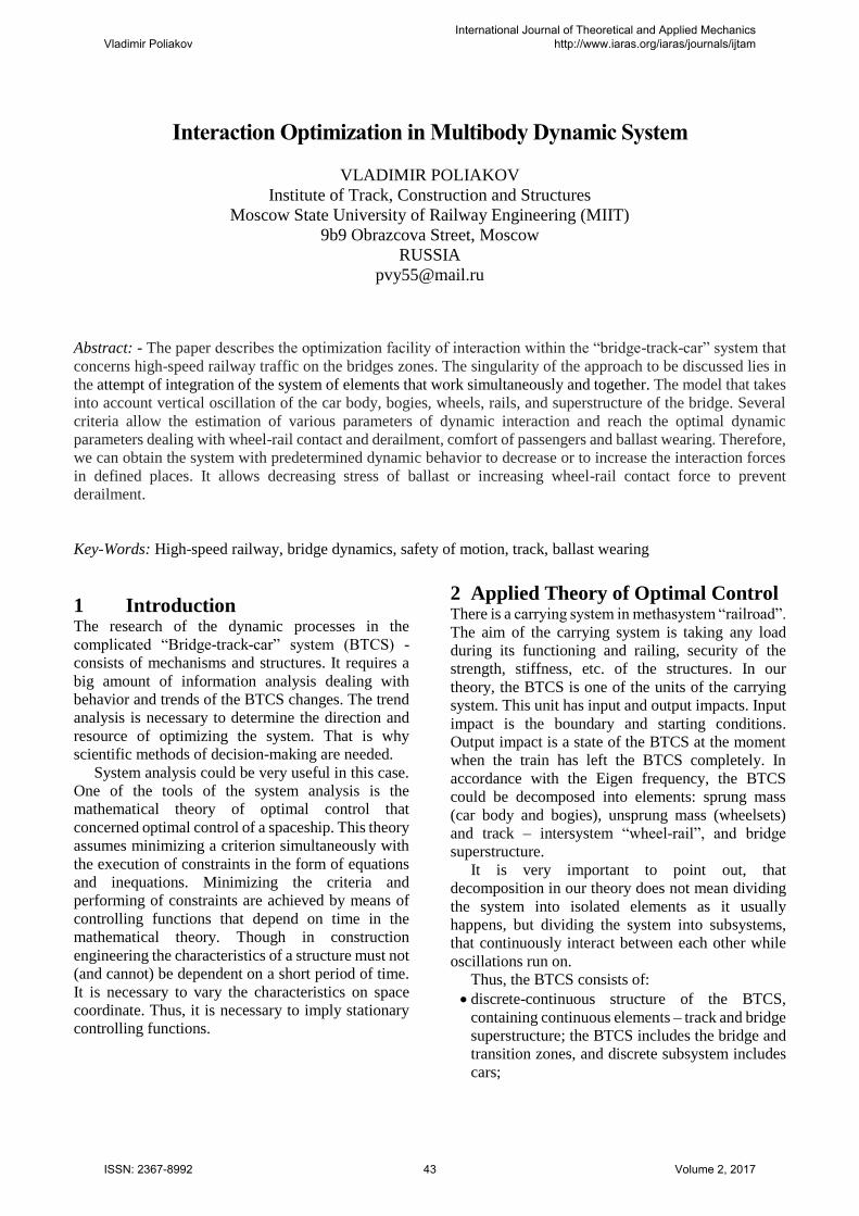
We supposed that optimization for heavier high-
speed train leads to optimal decision for lighter trains.
Figure 8 demonstrates success of the optimization for
the heavier perspective train and Figure 9 shows that
optimal structure for the perspective train remains
optimal for lighter CHR380 train. The average
meaning and standard deviation for CHR380 train are
lower than for the perspective train.
4.2 The optimal controlling functions The above mentioned results were achieved with the
single γ(x) controlling function that changes the rail
bed stiffness along the track. Our research showed
that the required changes within allowed range of the
rail bed stiffness can the obtained by grading under-
sleeper pads of mass production. The other types of
the controlling function in the cases mentioned are
not required which makes the track structure simpler,
in spite of obligatory usage of flange rails.
Sometimes the application of sleeper spacing
function δ(x) can be required. At last, α(x) controlling
function is used for bridge superstructure
optimization and it will be discussed in detail in
another paper.
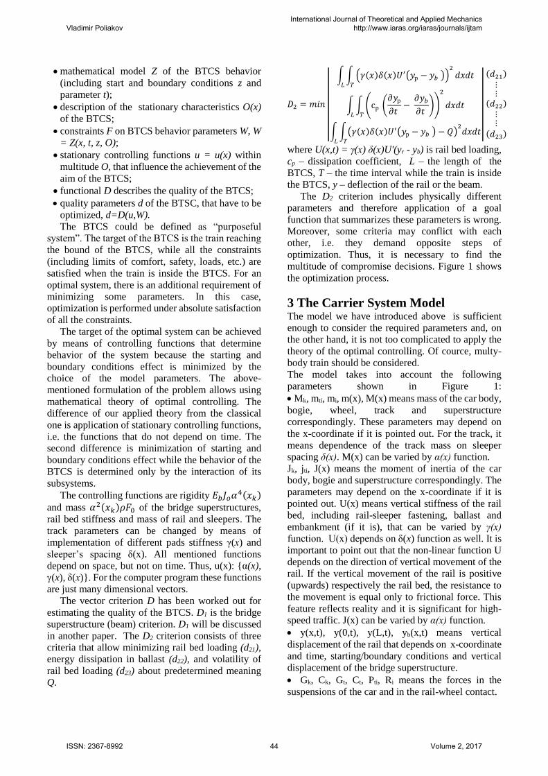
Because of integral character of the criterion (4),
the optimal result can be achieved with several
different controlling functions. Managing of
optimization process allows obtaining technically
reasonable controlling function. Figure 10 shows the
unreasonable version of optimal γ(x) function. The
aim of optimization consists in getting some
reasonable version of optimal controlling function
(Figure 11). Slight deviations of the function result
from discrete character of the optimization process.
These deviations are negligible and can be presented
by a line.
If the single controlling function application is
deficient several controlling functions can be used
simultaneously (Figure 12). Figure 11 and Figure 12
show the significance of the integral carrier system
(BTCS) research instead of separate consideration of
different parts of the BTCS because optimal structure
of the track depends on dynamic properties of the
bridge superstructure.
4 Conclusion The developed concept of integrated carrying system
including bridge superstructures, track and cars takes
into account the interaction inside the system.
Controlling of dynamic interaction within
“bridge-track-car” system at the design stage allows
estimation and assurance of safety level. For ensuring
safety and acceptable ballast wearing at the high
speed, it is necessary to explore the whole system.
The research showed the importance of the integral
system dynamic analysis without application of
multiple hypothesis. Thus, the applied theory of
optimal controlling was developed. The applied
theory allows design the system of predicted
behavior.
Planning of motion within many-dimensional
behavior and estimation spaces by means of vector-
specified controlling functions may be considered as
a step forward to development of artificial
intelligence in a certain science. The computer
program can make decisions concerning technical
parameters of the BTCS on the base of analysis of
great amount of information and the designer makes
a final decision about the acceptability of the
computer-aided design.
References:
[1] Polyakov V., "Dynamic Interaction within a
"Bridge-Track-Car" System on a High-Speed
Railway", in J. Pombo, (Editor), "Proceedings
of the Third International Conference on
Railway Technology: Research, Development
and Maintenance", Civil-Comp Press,
Stirlingshire, UK, Paper 136, 2016.
doi:10.4203/ccp.110.136
[2] Poliakov V.Y., “Optimal bridge superstructures
synthesis for high-speed railways”, Structural
Mechanics and Constructions Designing, 3 35-
42, Moscow, Russia, 2016.
[3] Poliakov V.Y., “Safety of high speed traffic on
bridges”, World of Transport and
Transportation Journal, 6, 182-188, Moscow,
Russia, 2014.
[4] Poliakov V.Y., “Computational modeling of the
vehicle–structure interaction on high-speed
railways”, Structural Mechanics and
Constructions Designing, 2, 54-60, Moscow,
Russia, 2016.
[5] N. Matsumoto & K. Asanuma. Some
experiences on track-bridge interaction in Japan.
Track-Bridge Interaction on High-Speed
Railways, 2009 Taylor & Francis Group,
London, UK, pp. 80-97.
Vladimir PoliakovInternational Journal of Theoretical and Applied Mechanics
http://www.iaras.org/iaras/journals/ijtam
ISSN: 2367-8992 46 Volume 2, 2017

Figure 1: The scheme of solving the BTCS optimization
Figure 2: The model of BTCS
Figure 3: An example of vertical wheel-rail contact force before and after optimization.
0.00E+00
5.00E+04
1.00E+05
1.50E+05
2.00E+05
2.50E+05
2.7
0E-
01
2.9
8E-
01
3.2
6E-
01
3.5
4E-
01
3.8
2E-
01
4.1
0E-
01
4.3
8E-
01
4.6
6E-
01
4.9
4E-
01
5.2
2E-
01
5.5
0E-
01
5.7
8E-
01
6.0
6E-
01
6.3
4E-
01
6.6
2E-
01
6.9
0E-
01
7.1
8E-
01
7.4
5E-
01
7.7
3E-
01
8.0
1E-
01
8.2
9E-
01
8.5
7E-
01
8.8
5E-
01
9.1
3E-
01
9.4
1E-
01
9.6
9E-
01
9.9
7E-
01
1.0
3E+
00
1.0
5E+
00
Wh
ee
l-ra
il co
nta
ct f
orc
e R
, N
Time, sec
R2-2 iteration 1
R2-2 iteration 6
Vladimir PoliakovInternational Journal of Theoretical and Applied Mechanics
http://www.iaras.org/iaras/journals/ijtam
ISSN: 2367-8992 47 Volume 2, 2017

Figure 4: Vertical forces of four wheels of the car of a train during motion through the bridge before
optimization
Figure 5: Vertical forces of four wheels of the car of a train during motion through the bridge after optimization
Figure 6: Vertical minimal wheel-rail contact force Rmin and D criterion
0.00E+00
2.50E+04
5.00E+04
7.50E+04
1.00E+05
1.25E+05
1.50E+05
1.75E+05
2.00E+05
0.3
25
0.3
58
0.3
90
0.4
23
0.4
55
0.4
88
0.5
20
0.5
53
0.5
85
0.6
18
0.6
50
0.6
83
0.7
15
0.7
48
0.7
80
0.8
13
0.8
45
0.8
78
0.9
10
0.9
43
0.9
75
1.0
08
1.0
40
1.0
73
1.1
05
Wh
eel-
rail
con
tact
fo
rce
R, N
Time, sec
R2-1 R2-2
R2-3 R2-4
BRIDGE 34m
Static force 90 kN
motion
0.00E+00
2.00E+04
4.00E+04
6.00E+04
8.00E+04
1.00E+05
1.20E+05
1.40E+05
1.60E+05
1.80E+05
2.00E+05
0.2
60
0.2
93
0.3
25
0.3
58
0.3
90
0.4
23
0.4
55
0.4
88
0.5
20
0.5
53
0.5
85
0.6
18
0.6
50
0.6
83
0.7
15
0.7
48
0.7
80
0.8
13
0.8
45
0.8
78
0.9
10
0.9
43
0.9
75
Wh
eel-
rail
con
tact
fo
rce
R, N
Time, sec
R2-1
R2-2BRIDGE 34m
motion
Static force 90 kN
1, 7.5
2, 2.18 9, 2.09
2, 14.2
9, 24.6
0
5
10
15
20
25
1 2 3 4 5 6 7 8 9
D
Rmin, кН
iteration number
Vladimir PoliakovInternational Journal of Theoretical and Applied Mechanics
http://www.iaras.org/iaras/journals/ijtam
ISSN: 2367-8992 48 Volume 2, 2017

Figure 7: Rail bed load before optimization (perspective train)
Figure 8: Rail bed load after optimization (perspective train)
-50,000
-45,000
-40,000
-35,000
-30,000
-25,000
-20,000
-15,000
-10,000
-5,000
0
3.87E-01
4.08E-01
4.30E-01
4.51E-01
4.73E-01
4.94E-01
5.16E-01
5.37E-01
5.59E-01
5.80E-01
6.01E-01
6.23E-01
6.44E-01
6.66E-01
6.87E-01
7.09E-01
7.30E-01
7.52E-01
7.73E-01
7.95E-01
8.16E-01
8.38E-01
8.59E-01
8.81E-01
9.02E-01
9.24E-01
9.45E-01
Ra
il b
ed
lo
ad
, N
Time, sec
Q2-1 Q2-2
Q2-3 Q2-4
Q average = -3.08Е+04 Std. deviation 2.79+03
motion BRIDGE
-30,690
-50,000
-45,000
-40,000
-35,000
-30,000
-25,000
-20,000
-15,000
-10,000
-5,000
0
3.58E-01
3.80E-01
4.01E-01
4.23E-01
4.44E-01
4.66E-01
4.87E-01
5.08E-01
5.30E-01
5.51E-01
5.73E-01
5.94E-01
6.16E-01
6.37E-01
6.59E-01
6.80E-01
7.02E-01
7.23E-01
7.45E-01
7.66E-01
7.88E-01
8.09E-01
8.31E-01
8.52E-01
8.74E-01
8.95E-01
9.17E-01
9.38E-01
Ra
il b
ed
lo
ad
, N
Time, sec
Q2-1 Q2-2
Q2-3 Q2-4
Q average = -2.62E+04Std. deviation =1.41E+03
Vladimir PoliakovInternational Journal of Theoretical and Applied Mechanics
http://www.iaras.org/iaras/journals/ijtam
ISSN: 2367-8992 49 Volume 2, 2017
Figure 9: Rail bed load under the second car of CHR380 train after track optimization for perspective train
Figure 10: The unreasonable version of optimal γ(x) function
-50,000
-45,000
-40,000
-35,000
-30,000
-25,000
-20,000
-15,000
-10,000
-5,000
0
3.56E-01
3.78E-01
3.99E-01
4.21E-01
4.42E-01
4.63E-01
4.85E-01
5.06E-01
5.28E-01
5.49E-01
5.70E-01
5.92E-01
6.13E-01
6.34E-01
6.56E-01
6.77E-01
6.99E-01
7.20E-01
7.41E-01
7.63E-01
7.84E-01
8.06E-01
8.27E-01
8.48E-01
8.70E-01
8.91E-01
9.12E-01
9.34E-01
Ra
il b
ed
lo
ad
, N
Q2-1Q2-2Q2-3
Q average = -2.03E+04 НStd. deviation = 1.37кН
0.00E+00
2.00E-01
4.00E-01
6.00E-01
8.00E-01
1.00E+00
1.20E+00
1 6
11
16
21
26
31
36
41
46
51
56
61
66
71
76
81
86
91
96
10
1
10
6
11
1
11
6
12
1
12
6
13
1
13
6
14
1
14
6
Sleepers
Vladimir PoliakovInternational Journal of Theoretical and Applied Mechanics
http://www.iaras.org/iaras/journals/ijtam
ISSN: 2367-8992 50 Volume 2, 2017

Figure 11: The reasonable version of optimal γ(x) function
Figure 12: The optimal controlling functions in case of less rigid superstructure
0.00E+00
2.00E-01
4.00E-01
6.00E-01
8.00E-01
1.00E+00
1.20E+00
1.40E+00
1 6
11
16
21
26
31
36
41
46
51
56
61
66
71
76
81
86
91
96
10
1
10
6
11
1
11
6
12
1
12
6
13
1
13
6
14
1
BRIDGE
ACTIVE γ(x) ZONE
0
0.2
0.4
0.6
0.8
1
1.2
1.4
1.6
1 4 7 10 13 16 19 22 25 28 31 34 37 40 43 46 49 52 55 58 61 64 67 70 73 76 79 82 85 88 91
𝜸(𝒙)
𝜹(𝒙)
Vladimir PoliakovInternational Journal of Theoretical and Applied Mechanics
http://www.iaras.org/iaras/journals/ijtam
ISSN: 2367-8992 51 Volume 2, 2017