interaction analysis of intze tank-fluid-layered soil
TRANSCRIPT

VOL. 10, NO. 2, FEBRUARY 2015 ISSN 1819-6608
ARPN Journal of Engineering and Applied Sciences
©2006-2015 Asian Research Publishing Network (ARPN). All rights reserved.
www.arpnjournals.com
940
INTERACTION ANALYSIS OF INTZE TANK-FLUID-LAYERED SOIL SYSTEM
Neeraj Tiwari and M.S. Hora
Department of Civil Engineering, Maulana Azad National Institute of Technology, Bhopal, India E-Mail: [email protected]
ABSTRACT
The non-interaction analysis of over head water tank assumes that columns rest on unyielding supports. In reality, the structure is supported by deformable soil strata which deforms unevenly under the action of loads and hence causes redistribution of forces in the components of overhead water tank. In the present work, 3-D interaction analysis of intze type water tank-fluid-layered soil system is carried out using ANSYS software to evaluate the principal stresses in different parts of the tank and supporting layered soil mass. The resultant deflection, von-Mises stress and neural frequency of the tank are also evaluated under different filling conditions of the intze tank. The intze tank, supporting frame, foundation and soil mass are considered to act as single compatible structural unit for more realistic analysis. The tank, foundation and soil are considered to be follow linear stress-strain relationship. The natural frequency of the tank is evaluated for different filling conditions and comparison is made between the non-interaction and interaction analyses. Keywords: fluid-structure interaction, Intze tank, non-interaction analysis, finite element analysis, layered soil, principal stresses, natural frequency. 1. INTRODUCTION
The soil-structure interaction is a complex phenomenon which involves mechanism of interaction between various components of intze type water tank-fluid-layered soil system. In common design practice, interaction between soil, foundation and tank structure is neglected to simplify the structural analysis. A stress analyst generally ignores the influence of the settlements of supporting soil on the structural behavior of the super-structure. In addition to this, the effect of the stiffness of the structure is disregarded in evaluating the foundation settlements. Earlier studies have indicated that interaction effects are quite significant, particularly for the tank resting on highly compressible soils.
The elevated water tanks are subjected to lateral and torsional vibrations due to wind and seismic forces. These lateral forces physically induce two different types of vibration in the water of the tank. A part of the water at the upper portion of tank participates in sloshing motion (convective) with a longer period, while rest of the water at the bottom portion of the tank experiences the same impulsive vibration as the tank container is rigidly attached with container wall. The differential settlements, rotation of shaft or frame and stiffness of the tank cause redistribution of forces/stresses in the tank members. A more rational solution of such an interaction system can be achieved by appropriate analysis. 2. BRIEF LITERATURE REVIEW
A lot of investigations have taken place in the area of soil-structure interaction of over-head and under-ground water tanks. Various investigators have proposed different approaches for solution of interaction problems from time to time in attempt to obtain more realistic analysis. They have quantified the effect of interaction behaviour and established that there is redistribution of forces/stresses in the water tank components.
Housner (1963) considered a model with two uncoupled masses and developed equations to compute the impulsive and sloshing liquid masses along with their location above the tank base and the stiffness of the convective mass spring. Usually only one convective mass is considered in practical design.
Haroun and Housner (1981) developed a three-mass model which takes into the tank-account the wall flexibility only. Ibrahim et al. (2001) presented a broad overview of sloshing dynamics, including both linear and nonlinear analyses, with emphasis on cylindrical and rectangular tanks.
Karamanos et al. (2006) and Patkas and Karamanos (2007) developed a mathematical model for calculating linear sloshing effects in the dynamical response of horizontal cylindrical and spherical liquid containers under earthquake excitation.
Livaoglur. R. and Dogangun A. (2006) investigated the effects of foundation embedment on the seismic behaviour of fluid-elevated tank-foundation-soil system with a structural frame supporting the fluid containing tank. Six different soil types defined in the seismic codes were considered. Both the sloshing effects of the fluid and soil-structure interaction of the elevated tanks resting on these six different soils were included in the analyses.
Karamanos et al. (2006) proposed a methodology based on a ‘‘convective-impulsive’’ decomposition of the liquid-vessel motion and a semi-analytical solution of sloshing in non-deformable containers by which the seismic forces can be estimated. Additionally, the effects of the support structure flexibility are also considered.
Livaoglu et al. (2007) presented simplified procedures for seismic analysis for elevated tanks considering fluid-structure-soil interaction Ten different models weree analyzed using mechanical and finite-

VOL. 10, NO. 2, FEBRUARY 2015 ISSN 1819-6608
ARPN Journal of Engineering and Applied Sciences
©2006-2015 Asian Research Publishing Network (ARPN). All rights reserved.
www.arpnjournals.com
941
element modelling techniques. The applicability of these ten models for the seismic design of the elevated tanks with four different subsoil classes is emphasized.
Sezen et al. (2008) carried out dynamic analysis using a simplified three-mass model and. investigated the seismic performance of elevated cylindrical tanks damaged during the Kocaeli earthquake (1999) in Turkey.
Dutta et al. (2009) presented comprehensive study on dynamic characteristics of RC elevated tanks supported by cylindrical shaft staging. The results were validated analytically using finite element analysis and by small-scale experimentation.
Amani et al. (2010) evaluated resonant frequencies in an RC elevated spherical container partially filled with water using finite element method and verified the results experimentally. The overall dynamical response of elevated spherical tanks subjected to horizontal base motion and free vibration and containing water at different levels were carried out. He investigated that for spherical tank, essentially three independent mass-motions are necessary; translation (structural), sloshing (convective) and pendulum motions. Therefore, three degrees of freedom is required for the analysis.
Moslemi, M. et al. (2011) presented the seismic response of liquid-filled elevated tank and studied the complexities associated with modelling of the conical shaped tanks. The fluid domain is modelled using displacement-based fluid elements (D-Fluid element). Both time history and modal analyses were performed for an elevated tank.
Chaduvula, U. et al. (2013) have an experimental investigation made on a 1:4 scale model of cylindrical steel elevated water tank subjected to combined horizontal, vertical and rocking motions, for earthquake excitation (accelerations) of 0.1g and 0.2g and increasing angle of rocking motion. It was investigated that the impulsive base shear and base moment increase with increase in earthquake acceleration, whereas, the convective base shear and base moment increase with increase in earthquake acceleration but decrease with increasing angular motion. Therefore, there is no
considerable effect of rocking motion found due to sloshing of water. The nonlinearity is found in the structure, when the impulsive pressure of tank decreases with increase in tank acceleration. 3. STATEMENT OF PROBLEM
In present problem, an overhead Intze water tank of capacity of 1000m3 resting on layered soil mass and subjected to gravity and water loading is analyzed. The elevated tank has a frame supporting structure in which columns are connected by the circumferential beam at regular intervals, at 4m, 8m and 12m height level. The container is filled with water. The container and the supporting structure are being used in most part of India located in earth quack prone zone. To investigate the interaction behaviour, the interaction analyses are carried out for the following four cases:
Case-1: The conventional/non-interaction analysis (NIA) considering the columns fixed at their bases.
Case-2: The linear interaction analysis of intze water tank without fluid (LIA-FSI) considering the tank foundation resting on layered soil mass consisting of five different soil types.
Case-3: The linear interaction analysis of intze water tank with fluid (LIA+FSI) considering the tank foundation resting on layered soil mass consisting of five different soil types.
Case-4: The vibration analysis (VIA) of intze water tank-foundation-layered soil mass to evaluate natural frequency, deflection and von-Mises stress for five modal shapes under different filling condition of the tank. The tank, foundation and supporting soil mass are considered to behave in linear elastic manner.
The geometric properties of tank, foundation, and soil mass are provided in Table-1. The material properties of tank, foundation, and soil mass are provided in Table-2.
Table-3 provides loading on different parts of the tank which include self weight and imposed load due to water.

VOL. 10, NO. 2, FEBRUARY 2015 ISSN 1819-6608
ARPN Journal of Engineering and Applied Sciences
©2006-2015 Asian Research Publishing Network (ARPN). All rights reserved.
www.arpnjournals.com
942
Table-1. Geometrical properties of tank, foundation and soil mass.
Name of component Description Data/Value
Intze water tank
Inside diameter of tank (D) 12.0 m
Average depth (0.75D) 9.0 m
Height of cylindrical portion of tank (2/3D )
8.0 m
Height of top dome (0.15 to 0.20D ) 2.0 m
Height of conical dome (0.2D ) 2.5 m
Height of bottom dome (0.15D ) 1.8 m
Diameter of staging (0.6 D ) 7.0 m
Bracing at 0.3D c/c 4.25 m
Dimension of bracing beam 500 mm x 700 mm
Foundation Diameter of foundation 6.0 m
Depth of foundation 1.2 m
Soil Semi-finite extent of soil mass 21 m x 14 m
Table-2. Material properties of tank and soil mass.
Material Type Young modulus kN/m2 Poission’s Ratio Density (kN/m3)
Concrete 25490 0.17 24.00
Soil type-1 35000 0.28 17.10
Soil type-2 40000 0.29 17.40
Soil type-3 45000 0.30 18.00
Soil type-4 55000 0.32 19.20
Soil type-5 60000 0.33 19.90
Table-3. Loads on various parts of tank.
Component Description Dead load + Live load
Intze water tank
Top dome 3.85 kN/m2
Maximum hoop tension at base of side wall
480.00 kN/m
Bottom ring beam 86.34 kN/m
Total load at base of conical dome slab 110.50 kN/m2
Total load at base of spherical dome 92.50 kN/m2
Total design load on circular girder 753.00 kN/m
Total vertical load on each Column 2234.64 kN
Foundation Axial load on all columns 19274.40 kN

VOL. 10, NO. 2, FEBRUARY 2015 ISSN 1819-6608
ARPN Journal of Engineering and Applied Sciences
©2006-2015 Asian Research Publishing Network (ARPN). All rights reserved.
www.arpnjournals.com
943
Figure-1. Model of intze tank.
Figure-2. Geometry of Tank. 4. F.E. IDEALIZATION
The linear interaction analysis (LIA) of the problem is carried out using ANSYS software. The top dome, side wall, bottom ring beam, conical dome, spherical dome, circular girder, column, foundation and soil mass are discretized with SOLID187 element which is a higher order 3-D 10-node element. SOLID187 has a quadratic displacement modelling and is well suited for modelling irregular meshes. The element is defined by 10 nodes having three degrees of freedom at each node: translations in the nodal x, y, and z directions. It has plasticity, hyper elasticity, creep, stress stiffening, large deflection and large strain capabilities. It also has mixed formulation capability for simulating deformations of nearly incompressible elasto-plastic materials, and fully incompressible hyper elastic materials. The structure of the water tank and soil mass are modeled using Solid-187 element as depicted in Figure-4.
The fluid within the tank is modeled with FLUID30 as shown in Figure-3. It is used for modelling the fluid medium and the interface in fluid/structure interaction problems. The element has 8 corner nodes with
four degrees of freedom per node: translations in the nodal x, y and z directions and pressure. The translations, however, are applicable only at nodes that are on the interface. The acceleration effects, such as in sloshing of water may be included. The element has the capability to include damping of sound absorbing material at the interface as well as damping within the fluid. The element can be used with other 3-D structural elements to perform unsymmetrical or damped modal, full harmonic and full transient method analyses .When there is no structural motion, the element is also applicable to modal analyses. The finite element discretization of the problem is shown in Figure-5
Figure-3. Geometry of SOLID187 element.
Figure-4. FLUID 30 element.
Figure-5. Finite element discretization of tank-foundation-layered soil system.

VOL. 10, NO. 2, FEBRUARY 2015 ISSN 1819-6608
ARPN Journal of Engineering and Applied Sciences
©2006-2015 Asian Research Publishing Network (ARPN). All rights reserved.
www.arpnjournals.com
944
The semi-infinite extent of the soil is considered of diameter 21m diameter and 14m depth which is achieved by trial and error. The extent of soil mass is decided where vertical and horizontal stresses/displacements are found to be negligible due to loading on the superstructure. The vertical displacements in soil mass are restrained at the bottom boundary whereas horizontal displacements are restrained at vertical boundaries.
It is found that for uniformly loaded circular area the vertical pressure intensity becomes negligible at a distance of 1.5 times the diameter of raft in the vertical direction and nearly 3 times the diameter in the horizontal direction. The Boussinesq’s isobar diagram (pressure bulb) is shown in Figure-6. Each layer of soil mass is idealized as isotropic, homogeneous. The element size is taken as 300 mm. The soil mass is discretized with finer meshes in close vicinity of footing where stresses are of higher order.
Figure-6. Formation of pressure bulb.
5. MESHING AND CONVERGENCE The solid element (SOLID 187) is used for
discretization of tank instead of surface element whereas the shell element is taken for modeling of surfaces. The thickness of side wall varies from top to bottom hence shell element is not suitable. The mesh size of 300 mm is finally adopted since principal stresses are found to converge for this mesh size. Figure-7 shows the variation of major principal stress with the size of element.
Figure-7. Variation of major principal stress with element size.
6. VALIDATION OF PROBLEM
The results obtained by the ANSYS software are validated with the results obtained by analytical method using IS-code method for the same geometry, material properties and loading conditions.
Table-4. Comparison of major principal stress in various components of water tank for
non-interaction analysis.
S. No.
Components
Major principal stress N/mm2
Analytical value (1)
FEM (NIA) (2)
% Difference (1) and (2)
1 Top dome 0.193 0.183 5.18
2. Top ring beam 0.912 0.903 1.00
3 Side wall 0.960 0.986 -1.25
4 Bottom ring
beam 1.000 0.957 4.30
5 Conical dome 1.160 1. 118 3.60
6 Bottom spherical
dome 0.990 1.009 -1.88
7 Bottom circular
girder 1.119 1.201 -6.82
8 Column 1.200 1.126 5.99

VOL. 10, NO. 2, FEBRUARY 2015 ISSN 1819-6608
ARPN Journal of Engineering and Applied Sciences
©2006-2015 Asian Research Publishing Network (ARPN). All rights reserved.
www.arpnjournals.com
945
Table-4 shows the values of major principal stress obtained by analytical method using IS-code) and finite element method (FEM). The values are found to be in close agreement. The percentage difference between analytical values and FEM values are found to be less than 6% for all components and the values obtained are found to be within permissible range. It is found that maximum value of major principal stress occurs in the bottom circular girder which is a critical component of the tank. 7. INTERACTION ANALYSIS
In the present work, the maximum principal stress and natural frequency under five modes of water tank with different filling conditions in various components of tank-fluid-soil-foundation system are evaluated due to NIA and LIA+FSI and discussed subsequently. The finite element analysis is carried out using added mass approach for fluid-structure interaction
with the distributed mass techniques. An equivalent cylinder is considered for the estimation of equivalent masses and stiffness of fluid. The impulsive mass obtained for the fluid is added to the mass of the container. In the present analysis the hydrodynamic pressure distribution acting on container wall is estimated by (Housner [09]).
The damping values for the reinforced concrete are taken as 5% for the impulsive mode and 0.5% for the convective mode as recommended in most of the literature.
The analyses are also carried out on layered model considering five different types of soil as supporting media. The soil properties considered are provided in Table-2. 7.1 Maximum major principal stress in various parts of the tank
Table-5. Values of maximum major principal stress in various parts of the tank for NIA and LIA.
S. No. Component of
the tank
Major principal stress N/mm2
Analytical values
( I S code ) (1)
FEM values % Difference (2) and (3) NIA (2) LIA+FSI (3)
1 Top dome 0.193 0.183 0.052 -71.58
2. Side wall 0.960 0.986 0.313 -68.25
3. Bottom ring
beam 1.000 0.957 0.484 -49.42
4. Conical dome 1.160 1. 118 1. 301 16.36
5. Spherical dome 0.990 1.009 1.448 42.60
6. Circular girder 1.119 1.201 1.823 51.79
7. Column 1.200 1.126 0.9212 -18.18
8. Foundation - - -0.3271 -
9. Soil - - -0.0196 -
Table-5 shows the values of the maximum
principal stress in various components of the interaction system and analytical values using IS- Code method. The values of maximum principal stress obtained using analytical method and FEM are found to be in close agreement. The interaction analysis causes significant decrease in the maximum principal stress in top dome, side wall, bottom ring beam and column whereas significant increase is found in the conical dome, spherical dome and circular girder. The interaction analysis causes significant decrease of nearly 71% in the maximum principal stress in the top dome, 68% in the side wall, 49% in the bottom ring beam and 18% in the columns. The increase of nearly 16% is found in the maximum principal stress in conical dome, 42% in spherical dome and 51% in circular girder.
The magnitude of major principal stress is quite high in circular girder as compared to other components and therefore it is a critical component of the tank.
Livaoglu and Dogangu [11] considered 10 different models and calculated time period under sloshing mode and impulsive mode. They evaluated the maximum value for of base shear and the overturning moment for different models. The present analyses evaluates maximum principal stresses in different parts of the tank which shows that the circular girder of the tank is the most critical component and is prone to failure under vertical loading.
The first principal stress and von-Mises stress in the tank-foundation-soil system are shown in Figure-8 and Figure-9 respectively.
The pressure distribution (pressure bulb) below the soil mass is shown in Figure-10. The depth below ground level is found where the vertical pressure intensity in soil is found to be negligible.
In layered soil mass, softer soil (type-1) is placed just blow the foundation and soil type-2 to type-5 (harder soil) are placed below it.

VOL. 10, NO. 2, FEBRUARY 2015 ISSN 1819-6608
ARPN Journal of Engineering and Applied Sciences
©2006-2015 Asian Research Publishing Network (ARPN). All rights reserved.
www.arpnjournals.com
946
Figure-8. Major principal stress in the interaction system.
Figure-9. Von-Mises stress in the interaction system.
Figure-10. Stress distribution in soil mass. 7.2 Natural frequency of five modes for different filling conditions of the tank for NIA and LIA
Table-6. Values of natural frequency of the tank for different filling conditions (1st mode shape).
Tank filling condition
Natural frequency (1st mode shape)
NIA Frequency
LIA-FSI Frequency (Structural)
LIA+ FSI (including sloshing effect)
Frequency von-Mises
stress N/mm2 Maximum
Deflection mm Empty condition 1.225 1.130 1.134 0.038 0.060 20% filled with
water 1.136 1.042 1.012 0.039 0.061
40% filled with water
0.982 0.904 0.884 0.035 0.053
60% filled with water
0.869 0.803 0.789 0.030 0.047
80% filled with water
0.789 0.724 0.709 0.026 0.043
Fully filled with water
0.733 0.643 0.643 0.025 0.038
LIA+FSI: Iinteraction analysis with fluid (water); LIA-FSI: Iinteraction analysis without fluid (water)

VOL. 10, NO. 2, FEBRUARY 2015 ISSN 1819-6608
ARPN Journal of Engineering and Applied Sciences
©2006-2015 Asian Research Publishing Network (ARPN). All rights reserved.
www.arpnjournals.com
947
Table-6 shows the values of natural frequency for NIA, LIA-FSI and LIA+FSI systems for 1st mode shape. It is found that there is a variation of nearly 7 to 12% in the values obtained for NIA and LIA+FSI systems. The maximum difference of nearly 12% is found under tank full condition. The percentage difference of nearly 9 to 12% is found for different filling conditions. The value of natural frequency decreases with increase in percentage filling in the tank. The percentage decrease of nearly 43% is found between tank empty and tank full conditions. The valuesof natural frequency is slightly reduced with fluid structure interaction. The maximum von-Mises stress and maximum deflection occurs at 20% tank fill condition Figure-11 shows that the maximum von-Mises stress occurs under 1st mode shape with 20% filled condition. Figure-12 shows the deflected shape under 1st mode shape with 20% filled condition.
Figure-11. Maximum von-Mises stress for 1st mode shape with 20% filled condition.
Figure-12. Deflected shape for 1st mode shape with 20% filled condition.
Table-7. Values of natural frequency of the over head water tank for different filling condition (2nd mode shape).
Tank filling condition
Natural frequency (2nd mode shape)
NIA Frequency
LIA-FSI Frequency (Structural)
LIA+ FSI (including sloshing effect)
Frequency von-Mises
stress N/mm2 Max. Deflection
mm.
Empty condition 1.233 5.920 5.924 0.178 0.085
20% filled with water 1.141 5.852 5.365 0.165 0.077
40% filled with water 0.986 5.635 5.723 0.179 0.086
60% filled with water 0.873 5.301 5.690 0.177 0.083
80% filled with water
0.783 4.857 5.531 0.176 0.077
Fully filled with water
0.734 4.223 5.401 0.167 0.076
VOL. 10, NO. 2, FEBRUARY 2015 ISSN 1819-6608
ARPN Journal of Engineering and Applied Sciences
©2006-2015 Asian Research Publishing Network (ARPN). All rights reserved.
www.arpnjournals.com
948
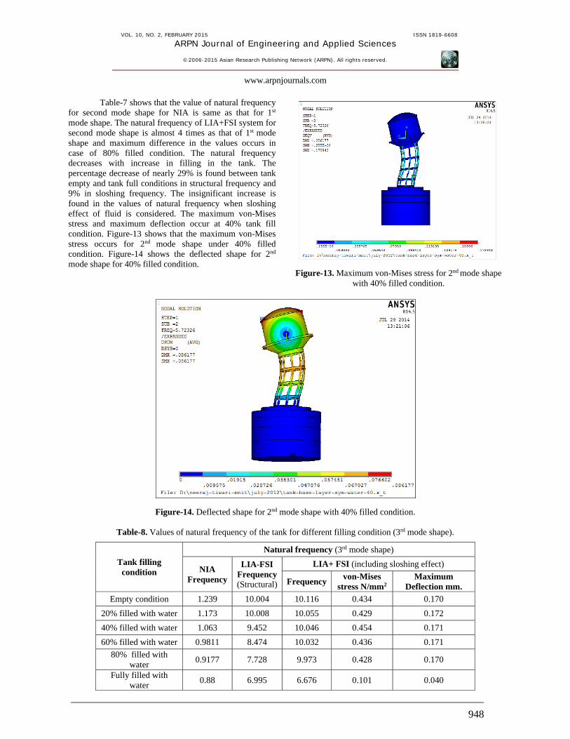
Table-7 shows that the value of natural frequency for second mode shape for NIA is same as that for 1st
mode shape. The natural frequency of LIA+FSI system for second mode shape is almost 4 times as that of 1st mode shape and maximum difference in the values occurs in case of 80% filled condition. The natural frequency decreases with increase in filling in the tank. The percentage decrease of nearly 29% is found between tank empty and tank full conditions in structural frequency and 9% in sloshing frequency. The insignificant increase is found in the values of natural frequency when sloshing effect of fluid is considered. The maximum von-Mises stress and maximum deflection occur at 40% tank fill condition. Figure-13 shows that the maximum von-Mises stress occurs for 2nd mode shape under 40% filled condition. Figure-14 shows the deflected shape for 2nd
mode shape for 40% filled condition.
Figure-13. Maximum von-Mises stress for 2nd mode shape with 40% filled condition.
Figure-14. Deflected shape for 2nd mode shape with 40% filled condition.
Table-8. Values of natural frequency of the tank for different filling condition (3rd mode shape).
Tank filling condition
Natural frequency (3rd mode shape)
NIA Frequency
LIA-FSI Frequency (Structural)
LIA+ FSI (including sloshing effect)
Frequency von-Mises
stress N/mm2 Maximum
Deflection mm.
Empty condition 1.239 10.004 10.116 0.434 0.170
20% filled with water 1.173 10.008 10.055 0.429 0.172
40% filled with water 1.063 9.452 10.046 0.454 0.171
60% filled with water 0.9811 8.474 10.032 0.436 0.171
80% filled with water
0.9177 7.728 9.973 0.428 0.170
Fully filled with water
0.88 6.995 6.676 0.101 0.040

VOL. 10, NO. 2, FEBRUARY 2015 ISSN 1819-6608
ARPN Journal of Engineering and Applied Sciences
©2006-2015 Asian Research Publishing Network (ARPN). All rights reserved.
www.arpnjournals.com
949
Table-8 shows that the value of natural frequency for second mode shape for NIA is same as that for 1st
mode shape. The natural frequency of LIA+FSI system for 3rd mode shape is almost 7 times as that for 1st mode shape and maximum difference in the values occurs in case of 40% filled condition. The natural frequency decreases when percentage filling in the tank increases. The percentage decrease of nearly 30% is found between tank empty and tank full conditions in structural frequency and 34% in sloshing frequency. The insignificant increase is found in the values of natural frequency when sloshing effect of fluid is considered. The maximum von-Mises stress and maximum deflection occurs at 40% tank fill condition. Figure-15 shows that the maximum von-Mises stress occurs with 40% filled condition. Figure-16 shows the deflected shape for 3rd mode shape with 40% filled condition.
Figure-15. Maximum von-Mises stress for 3rd mode shape with 40% filled condition.
Figure-16. Deflected shape for 3rd mode shape with 20% filled condition.
Table-9. Values of natural frequency of the tank for different filling condition (4th mode shape).
Tank filling condition
Natural frequency (4th mode shape)
NIA Frequency
LIA-FSI Frequency (Structural)
LIA+ FSI (including sloshing effect)
Frequency von-Mises
stress N/mm2 Maximum
Deflection mm.
Empty condition 5.978 11.471 11.475 0.172 0.065
20% filled with water 5.834 10.711 16.184 0.747 0.231
40% filled with water 5.569 9.919 16.174 0.708 0.230
60% filled with water 5.256 9.882 16.165 0.703 0.229
80% filled with water 4.838 9.826 16.140 0.665 0.210
Fully filled with water 4.535 9.754 10.041 0.432 0.171
Table-9 shows the values of natural frequency for
4th mode shape. The natural frequency of LIA+FSI system for 4th mode shape is almost 3 times to that of natural
frequency for NIA and the maximum difference occurs under 80% filled condition. 4th mode natural frequency is less for tank empty and tank full condition, and for other
VOL. 10, NO. 2, FEBRUARY 2015 ISSN 1819-6608
ARPN Journal of Engineering and Applied Sciences
©2006-2015 Asian Research Publishing Network (ARPN). All rights reserved.
www.arpnjournals.com
950
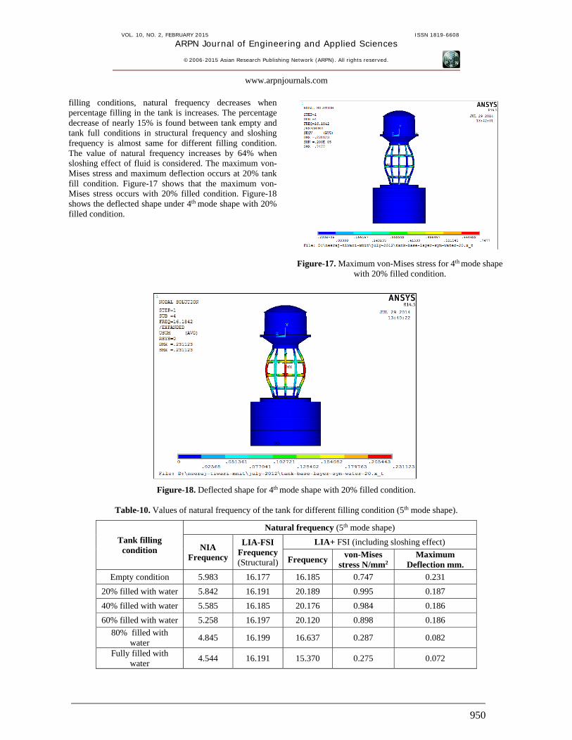
filling conditions, natural frequency decreases when percentage filling in the tank is increases. The percentage decrease of nearly 15% is found between tank empty and tank full conditions in structural frequency and sloshing frequency is almost same for different filling condition. The value of natural frequency increases by 64% when sloshing effect of fluid is considered. The maximum von-Mises stress and maximum deflection occurs at 20% tank fill condition. Figure-17 shows that the maximum von- Mises stress occurs with 20% filled condition. Figure-18 shows the deflected shape under 4th mode shape with 20% filled condition.
Figure-17. Maximum von-Mises stress for 4th mode shape with 20% filled condition.
Figure-18. Deflected shape for 4th mode shape with 20% filled condition.
Table-10. Values of natural frequency of the tank for different filling condition (5th mode shape).
Tank filling condition
Natural frequency (5th mode shape)
NIA Frequency
LIA-FSI Frequency (Structural)
LIA+ FSI (including sloshing effect)
Frequency von-Mises
stress N/mm2 Maximum
Deflection mm.
Empty condition 5.983 16.177 16.185 0.747 0.231
20% filled with water 5.842 16.191 20.189 0.995 0.187
40% filled with water 5.585 16.185 20.176 0.984 0.186
60% filled with water 5.258 16.197 20.120 0.898 0.186
80% filled with water
4.845 16.199 16.637 0.287 0.082
Fully filled with water
4.544 16.191 15.370 0.275 0.072
VOL. 10, NO. 2, FEBRUARY 2015 ISSN 1819-6608
ARPN Journal of Engineering and Applied Sciences
©2006-2015 Asian Research Publishing Network (ARPN). All rights reserved.
www.arpnjournals.com
951
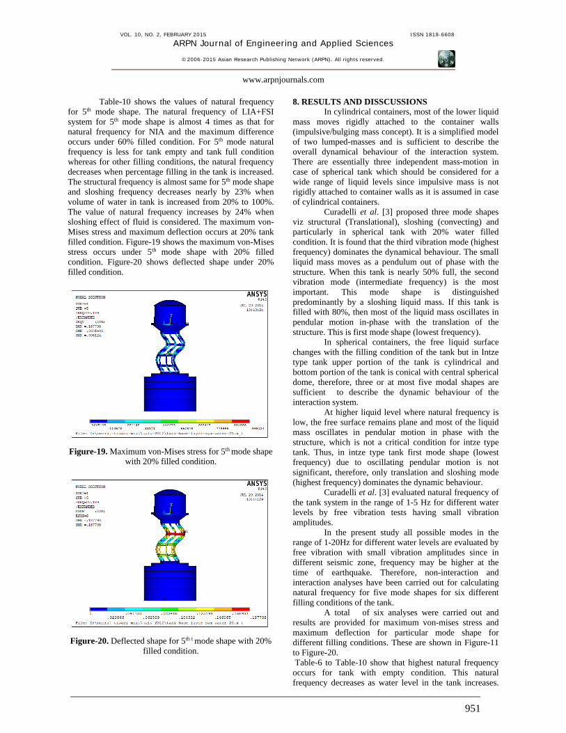
Table-10 shows the values of natural frequency for 5th mode shape. The natural frequency of LIA+FSI system for 5th mode shape is almost 4 times as that for natural frequency for NIA and the maximum difference occurs under 60% filled condition. For 5th mode natural frequency is less for tank empty and tank full condition whereas for other filling conditions, the natural frequency decreases when percentage filling in the tank is increased. The structural frequency is almost same for 5th mode shape and sloshing frequency decreases nearly by 23% when volume of water in tank is increased from 20% to 100%. The value of natural frequency increases by 24% when sloshing effect of fluid is considered. The maximum von-Mises stress and maximum deflection occurs at 20% tank filled condition. Figure-19 shows the maximum von-Mises stress occurs under 5th mode shape with 20% filled condition. Figure-20 shows deflected shape under 20% filled condition.
Figure-19. Maximum von-Mises stress for 5th mode shape with 20% filled condition.
Figure-20. Deflected shape for 5th t mode shape with 20% filled condition.
8. RESULTS AND DISSCUSSIONS In cylindrical containers, most of the lower liquid
mass moves rigidly attached to the container walls (impulsive/bulging mass concept). It is a simplified model of two lumped-masses and is sufficient to describe the overall dynamical behaviour of the interaction system. There are essentially three independent mass-motion in case of spherical tank which should be considered for a wide range of liquid levels since impulsive mass is not rigidly attached to container walls as it is assumed in case of cylindrical containers.
Curadelli et al. [3] proposed three mode shapes viz structural (Translational), sloshing (convecting) and particularly in spherical tank with 20% water filled condition. It is found that the third vibration mode (highest frequency) dominates the dynamical behaviour. The small liquid mass moves as a pendulum out of phase with the structure. When this tank is nearly 50% full, the second vibration mode (intermediate frequency) is the most important. This mode shape is distinguished predominantly by a sloshing liquid mass. If this tank is filled with 80%, then most of the liquid mass oscillates in pendular motion in-phase with the translation of the structure. This is first mode shape (lowest frequency).
In spherical containers, the free liquid surface changes with the filling condition of the tank but in Intze type tank upper portion of the tank is cylindrical and bottom portion of the tank is conical with central spherical dome, therefore, three or at most five modal shapes are sufficient to describe the dynamic behaviour of the interaction system.
At higher liquid level where natural frequency is low, the free surface remains plane and most of the liquid mass oscillates in pendular motion in phase with the structure, which is not a critical condition for intze type tank. Thus, in intze type tank first mode shape (lowest frequency) due to oscillating pendular motion is not significant, therefore, only translation and sloshing mode (highest frequency) dominates the dynamic behaviour.
Curadelli et al. [3] evaluated natural frequency of the tank system in the range of 1-5 Hz for different water levels by free vibration tests having small vibration amplitudes.
In the present study all possible modes in the range of 1-20Hz for different water levels are evaluated by free vibration with small vibration amplitudes since in different seismic zone, frequency may be higher at the time of earthquake. Therefore, non-interaction and interaction analyses have been carried out for calculating natural frequency for five mode shapes for six different filling conditions of the tank.
A total of six analyses were carried out and results are provided for maximum von-mises stress and maximum deflection for particular mode shape for different filling conditions. These are shown in Figure-11 to Figure-20. Table-6 to Table-10 show that highest natural frequency occurs for tank with empty condition. This natural frequency decreases as water level in the tank increases.

VOL. 10, NO. 2, FEBRUARY 2015 ISSN 1819-6608
ARPN Journal of Engineering and Applied Sciences
©2006-2015 Asian Research Publishing Network (ARPN). All rights reserved.
www.arpnjournals.com
952
The lowest natural frequency occurs under tank full condition. The magnitude of natural frequency is more for higher mode shape.
The natural frequencies provided by NIA are almost same for first, second and third mode shapes and it is also same for fourth and fifth mode shape. The mode shape with exactly similar natural frequencies represent the same mode in two orthogonal directions x and y). The natural frequency of the water tank does not depend on the type of subsoil under vertical loading. 9. CONCLUSIONS In the present work, the linear interaction analysis of intze water tank-fluid-layered soil system is presented under gravity and water loading to investigate the interaction behaviour. Each individual layer of soil mass is considered as homogeneous material. The following important research findings are summarized below: a) The interaction effect causes increase in the stresses
which vary in the range of 16-51% in various components of the tank. The maximum principal stress occurs in the circular girder which is a critical component of the tank. The decrease of nearly 18% is found in the maximum principal stress in the columns.
b) The insignificant interaction effect is found in the principal stresses, deflection and natural frequency in various components due to layered soil mass compared to non layered system.
c) The natural frequency of the interaction system decreases as the weight of water increases in the tank. The natural frequency of the vibration up to fifth mode contributes to the dynamical response in the range of 1-20Hz for different filling conditions. Up to third mode NIA gives almost same natural frequency but natural frequency for (LIA+FSI) increases from 1-20Hz up to fifth mode shape. These natural frequencies are very useful for harmonic and transient analysis since the tank collapses as and when wind load frequency matches with the natural frequency of tank for any mode causing resonance to occur.
d) The interaction analysis causes significant increase in stress of various components of the interaction system. The increase of nearly 16% is found in conical dome, 42% in spherical dome and 51% in the circular girder. The significant decrease of nearly 18% is found in the maximum principal stress in the columns. The interaction effect causes decrease in the principal stress in top dome, side wall and bottom ring beam. The maximum principal stress occurs in the circular girder.
e) The principal stresses are found to be the same in various component of the tank for different type of soils. The insignificant effect is found due to layered soil system compared to single homogeneous layer.
f) The maximum von-Mises stress and maximum deflection take place between 20 to 40% filling condition of the tank under all five modes. It is due to the fact that the maximum sloshing effect is found
under this condition. The deflection and maximum von- Mises stresses increases with increase in mode shape.
g) The structural natural frequency of (LIA+FSI) and (LIA+FSI) systems (i.e. with and without sloshing effect) are same for first, second and third mode but the sloshing effect is found to be dominating at higher mode shape.
h) When the frequency of external force (due to secondary vibration, induced at the time of earth quake) match with the natural frequency of tank, resonance occurs. The resonance condition will be different for different filling condition of elevated water tank.
REFERENCES Aviles J, Perez-Rocha EL. 1998. Effect of foundation embedment during building-soil structure interaction. Earthquake Eng Struct Dyn. 27, 1523-1540. Aviles J, Suarez M. 2002. Effective periods and damping of building foundation systems including seismic wave effects. Eng Struct. 24, 553-562. Curadelli O., Ambrosini D., Mirasso A., Amani M. 2010. Resonant frequencies in an elevated spherical container partially filled with water: FEM and measurement. Journal of Fluids and Structures. 26, 148-159. Dutta SC, Jain SK, Murty VR. 2000. Alternate tank staging configurations with reduced torsional vulnerability. Soil Dyn Earthquake Eng. 19, 199-215. Dutta SC, Jain SK, Murty CVR. 2000. Assessing the seismic torsional vulnerability of elevated tanks with RC frame-type staging. Soil Dyn Earthquake Eng. 19, 183-97. Dutta SC, Jain SK, Murty CVR. 2001. Inelastic seismic torsional behaviour of elevated tanks. J Sound Vibrat. 242(1): 151-167. Dutta S, Mondal A, Dutta SC. 2004. Soil structure interaction in dynamic behaviour of elevated tanks with alternate frame staging configurations. J Sound Vibrat. 277, 825-853. Dutta S., Dutta S.C., Rana Roy. 2009. Dynamic behavior of R/C elevated tank with soil–structure interaction“, Engineering Structures. 31, 2617-2629. Housner GF. 1963. Dynamic behavior of water tanks. Bull Seismol Soc Am. 53, 381-387. Haroun MA, Temraz MK. 1992. Effects of soil-structure interaction on seismic response of elevated tanks. Soil Dyn Earthquake Eng. 11(2): 73-86.
VOL. 10, NO. 2, FEBRUARY 2015 ISSN 1819-6608
ARPN Journal of Engineering and Applied Sciences
©2006-2015 Asian Research Publishing Network (ARPN). All rights reserved.
www.arpnjournals.com
953
Livaog˘ lu R, Dog˘angu¨ A. 2004. A simple seismic analysis procedure for fluid-elevated tank-foundation/soil systems. Sixth International Conference on Advances in Civil Engineering (ACE 2004). I˙stanbul, Turkey. pp. 570-580. Livaog˘ lu R, Dog˘angu¨ n A. 2005. Seismic evaluation of fluid-elevated tank foundation/ soil systems in frequency domain. Struct. Engg. Mech. 21(1): 101-119. Livaog˘ lu R. 2005. Investigation of the earthquake behaviour of elevated tanks considering fluid-structure-soil interactions. PhD Thesis. (in Turkish) Karadeniz Technical University, Trabzon. Livaoglu R. and Dogangun A. 2006. Simplifid seismic analysis procedures for elevated tanks considering fluid-structure-soil interaction. Journal of Fluids and Structures. 22, 421-439. Livaoglu R., Dogangun A. 2007. Effect of foundation embedment on seismic behavior of elevated tanks considering fluid- structure-soil interaction. Soil dynamics and Earthquake Engineering, 27, 855-863. Lee WV. 1980. Effect of foundation embedment on soil-structure interaction. In: The 7th World Conference on Earthquake Engineering, Istanbul. Pp. 225-228. Marashi ES, Shakib H. 1997. Evaluations of dynamic characteristics of elevated water tanks by ambient vibration tests. In: Proceedings of the 4th International Conference on Civil Engineering. Tehran, Iran. I, 367-373. Moslemi M., Kianoush M. R., Pogorzelski W. 2011. Seismic response of liquid-filled elevated tanks. Engineering Structures. 33, 2074-2084. Resheidat RM, Sunna H. 1986. Behavior of elevated storage tanks during earthquakes. In: Proceedings of the 3rd US National Conference on Earthquake Engineering. 2143-54. Stewart PJ, Seed RB, Fenves GL. 1999. Seismic soil-structure interaction in buildings. II: empirical findings. J Geotechn Geoenviron Eng. 125(1): 38-48.