inter-relationships and stakeholders
TRANSCRIPT

Document No: AGES-SP-05-001 Rev. No: 1
Page 3 of 89
INTER-RELATIONSHIPS AND STAKEHOLDERS
a) The following are inter-relationships for implementation of this Specification:
i. ADNOC Upstream and ADNOC Downstream Directorates and
ii. ADNOC Onshore, ADNOC Offshore, ADNOC Sour Gas, ADNOG Gas Processing. ADNOC LNG,
ADNOC Refining, ADNOC Fertilisers, Borouge, Al Dhafra Petroleum, Al Yasat
b) The following are stakeholders for the purpose of this Specification:
ADNOC PT&CS Directorate.
c) This Specification has been approved by the ADNOC PT&CS is to be implemented by each ADNOC Group
company included above subject to and in accordance with their Delegation of Authority and other
governance-related processes in order to ensure compliance
d) Each ADNOC Group company must establish/nominate a Technical Authority responsible for compliance with
this Specification.
DEFINED TERMS / ABBREVIATIONS / REFERENCES
“ADNOC” means Abu Dhabi National Oil Company.
“ADNOC Group” means ADNOC together with each company in which ADNOC, directly or indirectly, controls
fifty percent (50%) or more of the share capital.
“Approving Authority” means the decision-making body or employee with the required authority to approve
Policies & Procedures or any changes to it.
“Business Line Directorates” or “BLD” means a directorate of ADNOC which is responsible for one or more
Group Companies reporting to, or operating within the same line of business as, such directorate.
“Business Support Directorates and Functions” or “Non- BLD” means all the ADNOC functions and the
remaining directorates, which are not ADNOC Business Line Directorates.
“CEO” means chief executive officer.
“Group Company” means any company within the ADNOC Group other than ADNOC.
“Standard Specification/ Guideline/Philosophy” means Centrifugal Pumps (API 610) Specification.
CONTROLLED INTRANET COPY
The intranet copy of this document located in the section under Group Policies on One ADNOC is the only controlled document. Copies or extracts of this document, which have been downloaded from the intranet, are uncontrolled copies and cannot be guaranteed to be the latest version.

Document No: AGES-SP-05-001 Rev. No: 1
Page 4 of 89
TABLE OF CONTENTS
INTER-RELATIONSHIPS AND STAKEHOLDERS ................................................................................... 3
GENERAL ................................................................................................................................................... 8
1. PURPOSE ......................................................................................................................................... 8
2. SCOPE .............................................................................................................................................. 8
3. DEFINED TERMS / ABBREVIATIONS / REFERENCES ................................................................ 8
4. NORMATIVE REFERENCES ........................................................................................................... 9
SECTION A – CONTRACTUAL REQUIREMENTS ................................................................................. 11
5. REFERENCE DOCUMENTS .......................................................................................................... 11
6. DOCUMENTS PRECEDENCE ....................................................................................................... 11
7. SPECIFICATION DEVIATION/CONCESSION CONTROL............................................................ 11
8. PROCESS SAFETY REQUIREMENTS [PSR] .............................................................................. 11
SECTION B – TECHNICAL REQUIREMENTS ........................................................................................ 12
9. TECHNICAL AMENDMENTS / SUPPLEMENTS TO API 610 ...................................................... 12
SECTION 1 – SCOPE ............................................................................................................................... 12
SECTION 2 – NORMATIVE REFERENCES ............................................................................................ 13
SECTION 3 – TERMS AND DEFINITIONS .............................................................................................. 14
SECTION 4.2 – CLASSIFICATION AND DESIGNATION ....................................................................... 15
SECTION 5.1 – UNITS .............................................................................................................................. 16
SECTION 5.3 – REQUIREMENTS ........................................................................................................... 16
SECTION 6.1 – GENERAL ....................................................................................................................... 17
SECTION 6.3 – PRESSURE CASINGS ................................................................................................... 21
SECTION 6.4 – NOZZLES AND PRESSURE CASING CONNECTIONS ............................................... 22
SECTION 6.5 – EXTERNAL NOZZLE FORCES AND MOMENTS ......................................................... 25
SECTION 6.6 – ROTORS ......................................................................................................................... 25
SECTION 6.7 – WEAR RINGS AND RUNNING CLEARANCES ............................................................ 26
SECTION 6.8 – MECHANICAL SHAFT SEALS ...................................................................................... 27
SECTION 6.9 – DYNAMICS ..................................................................................................................... 27
SECTION 6.10 – BEARINGS AND BEARING HOUSINGS ..................................................................... 29
Document No: AGES-SP-05-001 Rev. No: 1
Page 5 of 89
SECTION 6.11 – LUBRICATION .............................................................................................................. 32
SECTION 6.12 – MATERIALS ................................................................................................................. 32
SECTION 6.13 – NAMEPLATES AND ROTATION ARROWS ............................................................... 33
SECTION 7 – ACCESSORIES ................................................................................................................. 34
SECTION 7.1 – DRIVERS......................................................................................................................... 34
SECTION 7.2 – COUPLINGS AND GUARDS .......................................................................................... 38
SECTION 7.3 – BASEPLATES ................................................................................................................ 40
SECTION 7.4 – INSTRUMENTATION ...................................................................................................... 43
SECTION 7.5 – PIPING AND APPURTENANCES .................................................................................. 45
SECTION 7.6 – SPECIAL TOOLS ........................................................................................................... 49
SECTION 8 – INSPECTION, TESTING AND PREPARATION FOR SHIPMENT ................................... 49
SECTION 9 – SPECIFIC PUMP TYPES ................................................................................................... 50
SECTION 9.1 – SINGLE-STAGE OVERHUNG PUMPS .......................................................................... 50
SECTION 9.2 – BETWEEN-BEARINGS PUMPS (TYPES BB1, BB2, BB3 AND BB5) ......................... 50
SECTION 9.3 – VERTICALLY SUSPENDED PUMPS (TYPES VS1 THROUGH VS7) .......................... 52
SECTION 10 – VENDOR’S DATA ............................................................................................................ 57
10. ANNEX B – COOLING WATER AND LUBRICATION SYSTEM SCHEMATICS ......................... 58
11. ANNEX C – HYDRAULIC POWER RECOVERY TURBINES ....................................................... 70
12. ANNEX G – MATERIALS CLASS SELECTION GUIDANCE ....................................................... 72
13. ANNEX H – MATERIALS AND MATERIAL SPECIFICATIONS FOR PUMP PARTS .................. 81
14. ANNEX P – REQUIREMENTS FOR DUPLEX OR SUPER DUPLEX STAINLESS STEEL
CASTINGS ...................................................................................................................................... 82
15. SUPPLEMENTARY REQUIREMENTS .......................................................................................... 84
SECTION C – ADDITIONAL REQUIREMENTS....................................................................................... 85
16. SCOPE OF SUPPLY ...................................................................................................................... 85
17. QUALITY CONTROL AND ASSURANCE ..................................................................................... 85
18. MATERIAL CERTIFICATION ......................................................................................................... 85
19. INSPECTION & TESTING REQUIREMENTS ................................................................................ 85
20. SUB-CONTRACTORS / SUB- SUPPLIERS .................................................................................. 85

Document No: AGES-SP-05-001 Rev. No: 1
Page 6 of 89
21. SPARE PARTS ............................................................................................................................... 85
22. PAINTING, PRESERVATION & SHIPMENT ................................................................................. 86
23. INSULATION .................................................................................................................................. 86
24. COMMISSIONING .......................................................................................................................... 86
25. TRAINING ....................................................................................................................................... 86
26. DOCUMENTATION/MANUFACTURER DATA RECORDS .......................................................... 86
27. GUARANTEES & WARRANTY ..................................................................................................... 87
SECTION D – DATASHEETS AND DRAWINGS .................................................................................... 88
28. DATASHEETS TEMPLATES ......................................................................................................... 88
29. STANDARD DRAWINGS ............................................................................................................... 88
SECTION E – APPENDICES .................................................................................................................... 89
APPENDIX 1: GENERAL TECHNICAL AND CONTRACTUAL REQUIREMENTS FOR ROTATING
EQUIPMENT ................................................................................................................................... 89
APPENDIX 2: QUALITY ASSURANCE INSPECTION AND TESTING REQUIREMENTS .................... 89
APPENDIX 3: INFORMATION REQUIREMENTS ................................................................................... 89
APPENDIX 4: BUSINESS UNIT SPECIFC REQUIREMENTS ................................................................ 89
APPENDIX 5: INSTRUMENTATION AND CONDITION MONITORING REQUIREMENTS ................... 89
APPENDIX 6: LUBRICATION SYSTEM DESIGN REQUIREMENTS ..................................................... 89

Document No: AGES-SP-05-001 Rev. No: 1
Page 7 of 89
LIST OF TABLES
Table 1 – List of Abbreviations .............................................................................................................................. 9 Table 2 – Normative References ........................................................................................................................... 9 Table 3 – API 610 Technical Amendments: Section 1 – Scope ......................................................................... 12 Table 4 – API 610 Technical Amendments: Section 2 – Normative References ................................................ 13 Table 5 – API 610 Technical Amendments: Section 3 – Terms and Definitions ................................................. 14 Table 6 – API 610 Technical Amendments: Section 4 – General ....................................................................... 15 Table 7 – API 610 Technical Amendments: Section 5 – Requirements ............................................................. 16 Table 8 – API 610 Technical Amendments: Section 6 – Basic Design ............................................................... 17 Table 9 – API 610 Technical Amendments: Section 7 – Accessories ................................................................ 34 Table 10 – API 610 Technical Amendments: Section 8 – Inspection Testing & Preparation for Shipment ........ 49 Table 11 – API 610 Technical Amendments: Section 9 – Specific Pump Types ................................................ 50 Table 12 – API 610 Technical Amendments: Section 10 – SUPPLIER’s Data ................................................... 57 Table 13 – Required Capital Spares for Centrifugal Pumps ............................................................................... 85
LIST OF FIGURES
Figure 1 – Viscosity of Liquid Sulphur vs Temperature ....................................................................................... 35 Figure 2 – Effects of Hydrogen Sulphide on Viscosity of Molten Sulphur ........................................................... 36 Figure 3 – Typical Vertical Multi-Stage Centrifugal Pump Installation ................................................................ 55
Document No: AGES-SP-05-001 Rev. No: 1
Page 8 of 89
GENERAL
1. PURPOSE
1.1 This specification details the minimum technical requirements for Centrifugal Pumps of the horizontal, vertical and vertical inline type and hydraulic power recovery turbines for applications across ADNOC Business Units. Unless otherwise stated in this specification, the supplied equipment shall comply fully with the requirements of API 610 11th Edition, September 2010 (Ref. 1).
1.2 This specification shall be read in conjunction with the listed relevant equipment datasheets and the international standards referenced in Table 2. In addition, the following related appendices shall be considered as forming an integral part of the this specification: -
a. General Technical and Contractual Requirements for Rotating Equipment (Ref. 2)
b. QA Inspection and Testing Requirements (Ref. 3)
c. Information Requirements (Ref. 4)
d. Business Unit Specific Requirements (Ref. 5)
e. Instrumentation and Condition Monitoring Requirements (Ref. 6)
f. Lubrication System Design Requirements (Ref. 7)
2. SCOPE
2.1 This specification amends, supplements and deletes various clauses/ paragraphs of API Standard 610 11th Edition (Ref. 1). In addition, some new clauses have been added.
3. DEFINED TERMS / ABBREVIATIONS / REFERENCES
For generic Defined Terms/ Abbreviations/ References applicable to all rotating equipment refer to ‘General Technical and Contractual Requirements for Rotating Equipment (Ref. 2). Terms / Abbreviations / References relating specifically to Centrifugal Pumps are included below.

Document No: AGES-SP-05-001 Rev. No: 1
Page 9 of 89
3.1 List of Abbreviations
The abbreviations listed in Table 1 are those used in this document and related Appendices. Standard abbreviations for SI units of measure and abbreviations already defined in API 610 11th Edition (Ref. 1) are not shown. Refer to ‘General Technical and Contractual Requirements for Rotating Equipment’ (Ref. 2) for generic abbreviations applicable to all rotating equipment types.
Table 1 – List of Abbreviations
Abbreviation Definition
BEP Best Efficiency Point
HPRT Hydraulic Power Recovery Turbine
NPSHA Net Positive Suction Head Available
NPSHR Net Positive Suction Head Required
MPQT Manufacturer’s Procedure Qualification Test
4. NORMATIVE REFERENCES
The documents listed in Table 2 are normatively referenced in this document and are indispensable for its application. For dated references, only the edition cited applies. For undated references, the latest edition of the referenced document (including any amendments) applies. Refer to ‘General Technical and Contractual Requirements for Rotating Equipment’ (Ref. 2) for generic references applicable to all rotating equipment types.
Table 2 – Normative References
Ref. Document No. Title
1. ANSI/API Standard 610 11th Edition, Sept. 2010
Centrifugal Pumps for Petroleum, Petrochemical and Natural Gas Industries
2. Appendix 1 General Technical and Contractual Requirements for Rotating Equipment
3. Appendix 2 QA Inspection and Testing Requirements
4. Appendix 3 Information Requirements
5. Appendix 4 Business Unit Specific Requirements
6. Appendix 5 Instrumentation and Condition Monitoring Requirements
7. Appendix 6 Lubrication System Design Requirements
8. ASME B16.20:2017 Metallic Gaskets for Pipe Flanges
9. ASME B16.21:2016 Non-Metallic Flat Gaskets for Pipe Flanges
10. DGS-MG-001 Centrifugal Pumps (Amendments/Supplements to API 610)
11. AGMA 9002: 2014
Bores and Keyways for Flexible Couplings (Inch Series)
Document No: AGES-SP-05-001 Rev. No: 1
Page 10 of 89
Ref. Document No. Title
12. BS EN 1834-1:2000 Reciprocating internal combustion engines. Safety requirements for design and construction of engines for use in potentially explosive atmospheres. Group II engines for use in flammable gas and vapour atmospheres
13. BS 4082: Part 1 Specification for External Dimensions For Vertical In-Line Centrifugal Pumps

Document No: AGES-SP-05-001 Rev. No: 1
Page 11 of 89
SECTION A – CONTRACTUAL REQUIREMENTS
5. REFERENCE DOCUMENTS
Refer to ‘General Technical and Contractual Requirements for Rotating Equipment’, Appendix 1 (Ref. 2) for
applicable general references.
6. DOCUMENTS PRECEDENCE
Refer to ‘General Technical and Contractual Requirements for Rotating Equipment’, Appendix 1 (Ref. 2) for definition of Document Precedence.
The specifications and codes referred to in this standard shall, unless stated otherwise, be the latest approved issue at the time of Purchase Order placement.
7. SPECIFICATION DEVIATION/CONCESSION CONTROL
Refer to “General Technical and Contractual Requirements for Rotating Equipment”, Appendix 1 (Ref. 2) for
definition of Specification Deviation/ Concession Control.
8. PROCESS SAFETY REQUIREMENTS [PSR]
Where listed within this specification, the capitalised term SHALL [PSR] indicates a process safety requirement.
There are more Process Safety requirements which have been addressed in Appendix 5 (Ref. 6) and shall be
considered in design of Centrifugal Pumps concerning Instrumentation and Condition Monitoring Requirements.
Document No: AGES-SP-05-001 Rev. No: 1
Page 12 of 89
SECTION B – TECHNICAL REQUIREMENTS
9. TECHNICAL AMENDMENTS / SUPPLEMENTS TO API 610
9.1 The technical amendments applicable to API 610 Process Centrifugal Pumps are listed below in Table 3 to Table 12 inclusive, where referenced to each section of the API 610 standard (Ref. 1). The clause numbers listed within each table and each related amendment correspond to the same clause number within the API standard, where these are already included in the existing publication. These amendments shall take precedence over the relevant sections of API Standard 610 11th Edition, ‘Centrifugal Pumps for Petroleum, Petrochemical and Natural Gas Industries, September 2010’ (Ref. 1).
9.2 The amendments to each section are identified by the relevant clause number and the following operative descriptions shown in brackets against each related clause number to indicate the type of change, namely:-
(Add) Where words have been added to an existing API clause that has an existing clause number
(New) Where a completely new paragraph has been added to the API
(Modify) Where the words in an existing API clause have been modified
(Delete) Where the API clause no longer applies
9.3 In the absence of any below listed technical amendments, the requirements of the API 610 11th Edition standard (Ref. 1) shall apply in full.
Table 3 – API 610 Technical Amendments: Section 1 – Scope
API Clause No. Description of Change
SECTION 1 – SCOPE
1. (Add) Add the following sentence at the end of the first paragraph:- “The specific requirements relating to Hydraulic Power Recovery Turbines (HPRTs) are detailed in Annex C.” Add the following new paragraphs after the second paragraph:- “This international standard is not intended to cover specialist drilling operations.” “Vertical, in-line, close-coupled pumps shall also comply with the requirements of BS 4082: Part 1, Class R except for high speed pumps.”
Document No: AGES-SP-05-001 Rev. No: 1
Page 13 of 89
API Clause No. Description of Change
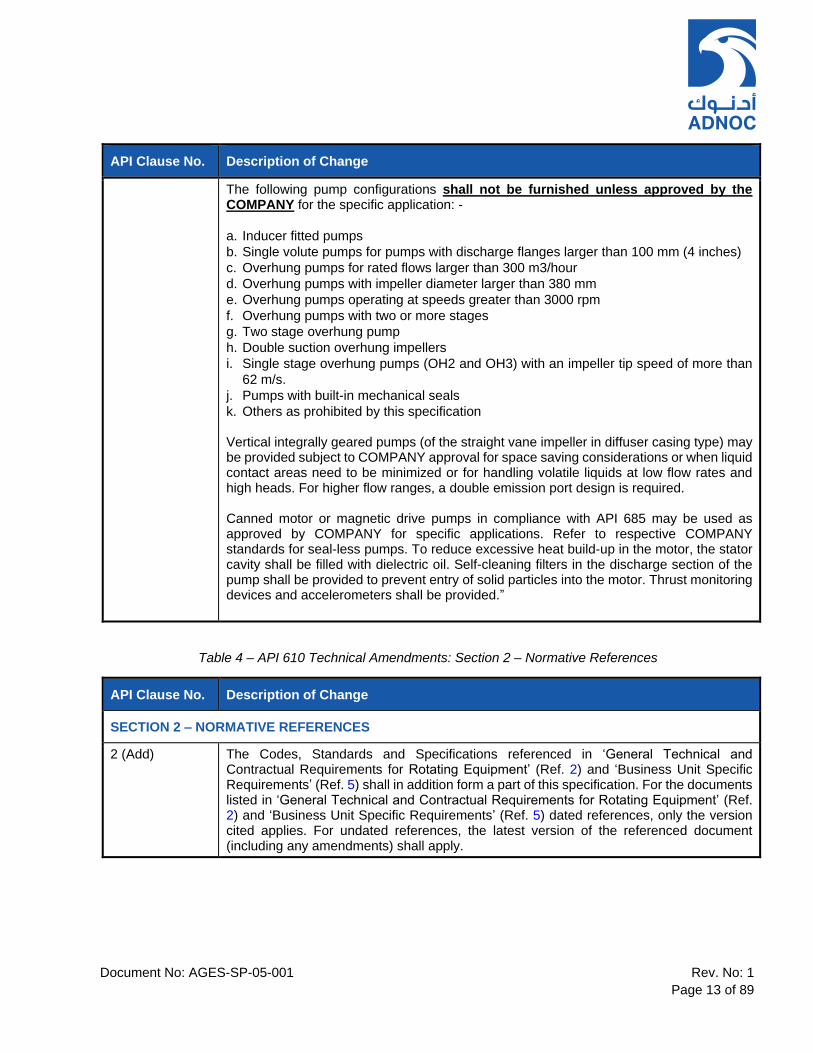
The following pump configurations shall not be furnished unless approved by the COMPANY for the specific application: -
a. Inducer fitted pumps
b. Single volute pumps for pumps with discharge flanges larger than 100 mm (4 inches)
c. Overhung pumps for rated flows larger than 300 m3/hour
d. Overhung pumps with impeller diameter larger than 380 mm
e. Overhung pumps operating at speeds greater than 3000 rpm
f. Overhung pumps with two or more stages
g. Two stage overhung pump
h. Double suction overhung impellers
i. Single stage overhung pumps (OH2 and OH3) with an impeller tip speed of more than
62 m/s.
j. Pumps with built-in mechanical seals
k. Others as prohibited by this specification Vertical integrally geared pumps (of the straight vane impeller in diffuser casing type) may be provided subject to COMPANY approval for space saving considerations or when liquid contact areas need to be minimized or for handling volatile liquids at low flow rates and high heads. For higher flow ranges, a double emission port design is required. Canned motor or magnetic drive pumps in compliance with API 685 may be used as approved by COMPANY for specific applications. Refer to respective COMPANY standards for seal-less pumps. To reduce excessive heat build-up in the motor, the stator cavity shall be filled with dielectric oil. Self-cleaning filters in the discharge section of the pump shall be provided to prevent entry of solid particles into the motor. Thrust monitoring devices and accelerometers shall be provided.”
Table 4 – API 610 Technical Amendments: Section 2 – Normative References
API Clause No. Description of Change
SECTION 2 – NORMATIVE REFERENCES
2 (Add) The Codes, Standards and Specifications referenced in ‘General Technical and Contractual Requirements for Rotating Equipment’ (Ref. 2) and ‘Business Unit Specific Requirements’ (Ref. 5) shall in addition form a part of this specification. For the documents listed in ‘General Technical and Contractual Requirements for Rotating Equipment’ (Ref. 2) and ‘Business Unit Specific Requirements’ (Ref. 5) dated references, only the version cited applies. For undated references, the latest version of the referenced document (including any amendments) shall apply.

Document No: AGES-SP-05-001 Rev. No: 1
Page 14 of 89
Table 5 – API 610 Technical Amendments: Section 3 – Terms and Definitions
API Clause No. Description of Change
SECTION 3 – TERMS AND DEFINITIONS
3.43 (Modify) Replace the definition of “Pressure Casing” with…. "Composite of all stationary pressure-containing parts of the pump, including all nozzles, seal chambers, seal gland and auxiliary process liquid piping permanently attached to the pump casing or seal chamber, but excluding the stationary and rotating parts of mechanical seals.” Note: Atmospheric side of seal gland, seal flush (piping) plan, auxiliary piping and valves are not part of pressure casing.
3.65 (New) Multistage Pump A multistage pump is defined as one of the following pump types with three (3) or more stages.
a) Horizontal, between bearings pump (BB3 or BB5) b) Vertical line shaft pump (VS1) c) Vertical Canned pump (VS6)
3.66 (New) Erosive Service Service containing solid particles of 50 microns or larger and having a total solids concentration greater that 100mg/m3, or when indicated as "erosive" on the equipment datasheet.
3.67 (New) Abrasive Service Service in which there is an expected wear rate of 0.1 mm (0.004 in) or more per year, or where hard particles larger than 100 µm (0.004 in) exist in quantities exceeding 100 mg/kg (100 ppm).
3.68 (New) NPSHR 40,000 hr The minimum NPSH required over the ‘Allowable Operating Region’ (refer to para. 6.1.12) capacities, for which the SUPPLIER will guarantee 40,000 hours of damage-free operation due to cavitation.
3.69 (New) Uninterrupted Operation Uninterrupted operation for a period of at least 40,000 hours or 5 years at the specified operating conditions. There shall be no requirement for pump overhaul during this period, only seal replacement (based on failures) may be allowed. This term shall not apply to pumps operating intermittently such as: - a) Pumps started and stopped automatically at intervals by process-operated controls b) Pumps started up and stopped manually for batch transfer
3.70 (New) High Energy Pump A high energy pump is a pump which develops a driver rating of 750kW or more at the specified rated conditions.
3.71 (New) Dirty Service Dirty service is typically heavy sludge.
Document No: AGES-SP-05-001 Rev. No: 1
Page 15 of 89
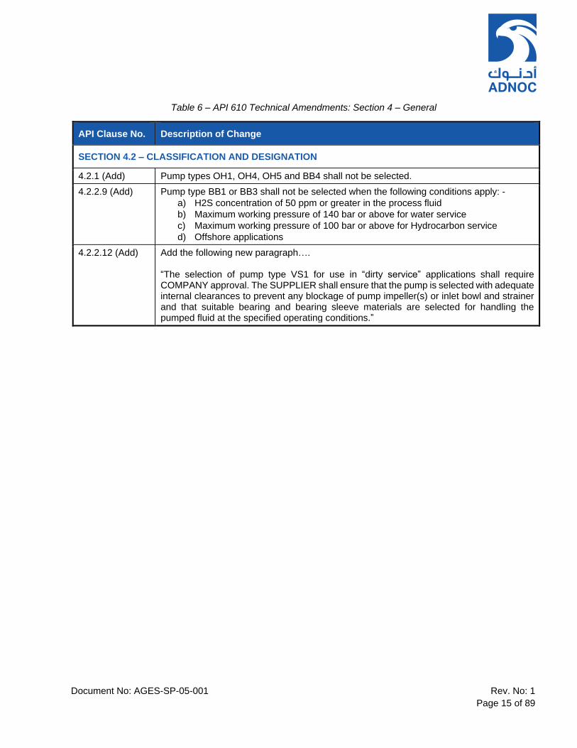
Table 6 – API 610 Technical Amendments: Section 4 – General
API Clause No. Description of Change
SECTION 4.2 – CLASSIFICATION AND DESIGNATION
4.2.1 (Add) Pump types OH1, OH4, OH5 and BB4 shall not be selected.
4.2.2.9 (Add) Pump type BB1 or BB3 shall not be selected when the following conditions apply: -
a) H2S concentration of 50 ppm or greater in the process fluid
b) Maximum working pressure of 140 bar or above for water service
c) Maximum working pressure of 100 bar or above for Hydrocarbon service
d) Offshore applications
4.2.2.12 (Add) Add the following new paragraph…. “The selection of pump type VS1 for use in “dirty service” applications shall require COMPANY approval. The SUPPLIER shall ensure that the pump is selected with adequate internal clearances to prevent any blockage of pump impeller(s) or inlet bowl and strainer and that suitable bearing and bearing sleeve materials are selected for handling the pumped fluid at the specified operating conditions.”
Document No: AGES-SP-05-001 Rev. No: 1
Page 16 of 89
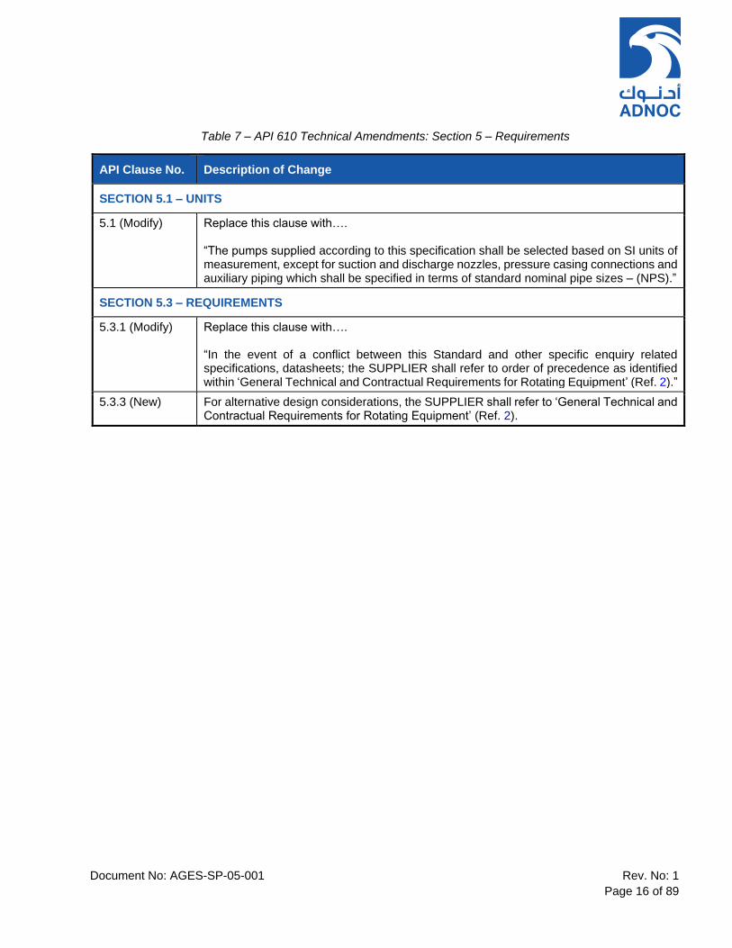
Table 7 – API 610 Technical Amendments: Section 5 – Requirements
API Clause No. Description of Change
SECTION 5.1 – UNITS
5.1 (Modify) Replace this clause with…. “The pumps supplied according to this specification shall be selected based on SI units of measurement, except for suction and discharge nozzles, pressure casing connections and auxiliary piping which shall be specified in terms of standard nominal pipe sizes – (NPS).”
SECTION 5.3 – REQUIREMENTS
5.3.1 (Modify) Replace this clause with…. “In the event of a conflict between this Standard and other specific enquiry related specifications, datasheets; the SUPPLIER shall refer to order of precedence as identified within ‘General Technical and Contractual Requirements for Rotating Equipment’ (Ref. 2).”
5.3.3 (New) For alternative design considerations, the SUPPLIER shall refer to ‘General Technical and Contractual Requirements for Rotating Equipment’ (Ref. 2).

Document No: AGES-SP-05-001 Rev. No: 1
Page 17 of 89
Table 8 – API 610 Technical Amendments: Section 6 – Basic Design
API Clause No. Description of Change
SECTION 6.1 – GENERAL
6.1.1 (Modify) Replace the first and second sentence of this API clause with…. “The equipment (including auxiliaries) covered by this international standard shall be designed and constructed for a minimum service life of 30 years and at least 5 years of uninterrupted operation, excluding shutdown of the equipment to perform routine maintenance or inspection.”
6.1.2 (Add) Notwithstanding the information provided by the CONTRACTOR, the SUPPLIER shall advise the CONTRACTOR, whether any of the specified pumped fluids or auxiliaries are flammable or hazardous based on his past experience in similar services. Appropriate design provisions shall be made by the SUPPLIER to suit the offered equipment for such hazardous and flammable products.
6.1.4 (Add) All the rated impellers shall have a diameter at least 5% larger than the minimum impeller size to reduce suction recirculation (which can lead to increased NPSHR), and 5% smaller than the maximum impeller size to allow for refinement of hydraulics and process requirements. The SUPPLIER shall confirm the actual margin on physical impeller diameter between rated, minimum and maximum impeller diameter in their proposal.
6.1.6 (Add) For variable speed applications, the pump SUPPLIER is responsible for designing the pump to ensure that the casing MAWP and all other components are adequately rated to withstand the maximum discharge pressure and shaft power developed at both maximum continuous speed and trip speed.
6.1.7 (Add) For all fluid applications including molten sulphur service, the pump SUPPLER is responsible for checking that the seal arrangement, axial thrust load and bearing life are in full compliance with this standard.
6.1.8 (Add) The Net Positive Suction Head Available (NPSHA) shall exceed the Net Positive Suction Head Required (NPSHR3) by: • At least 1 m throughout the entire operating range, from minimum continuous stable flow up to and including rated capacity and by a minimum of 0.3m at maximum system capacity at End Of Curve (EOC). • For pumps in vacuum or low-temperature (below 0°C) service, the margin between NPSHA and NPSH3 shall be at least 2 m at rated duty point and 0.3m at EOC. • For liquids containing dissolved gases, to avoid cavitation damage due to vapor induced flow path restrictions, NPSHA shall be 1.5 x NPSH3, with a minimum margin of 5 m between NPSHA and NPSH3. At EOC, margin shall be minimum 0.5m. • For special fluids used in gas treatment units such as Amine etc. higher margins may be required and shall be specified on datasheet in consultation with COMPANY. Tip speed limitations apply on these services (shall be lower than 55m/s.) • Inducers are acceptable only in OH6 and cryogenic pumps (completely submerged vertical type). • For all pumps, NPSHA in the “Preferred Operating Region” shall be greater than NPSHR 40,000hr. The mechanical as well as hydraulic performance inclusive of NPSHR3 for the complete range of operation of the quoted model shall have been established in a shop performance test.
Document No: AGES-SP-05-001 Rev. No: 1
Page 18 of 89
API Clause No. Description of Change
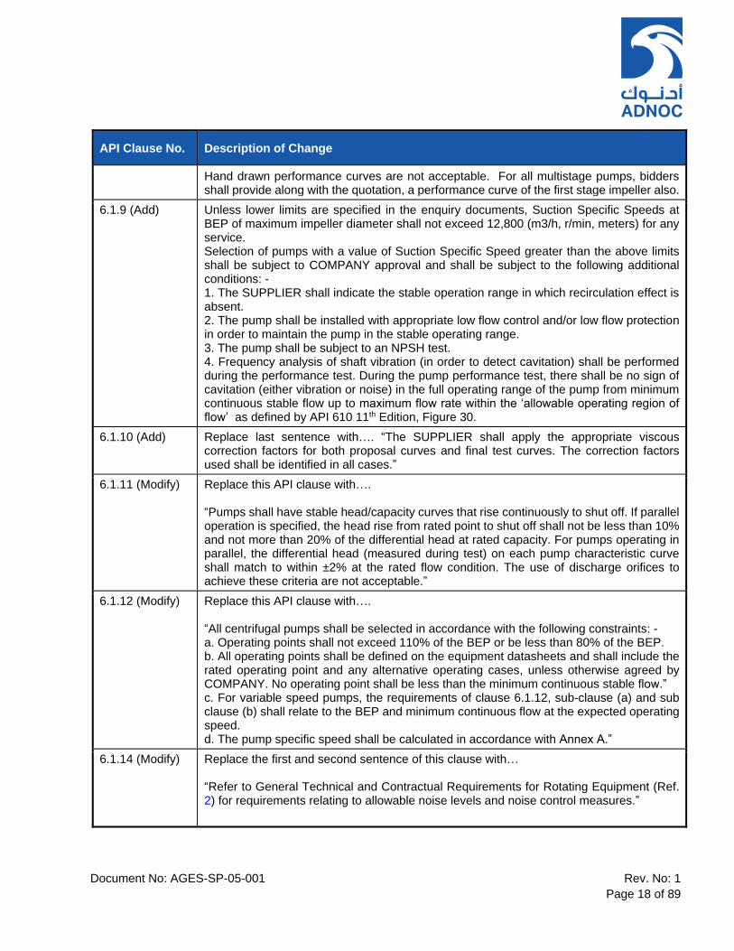
Hand drawn performance curves are not acceptable. For all multistage pumps, bidders shall provide along with the quotation, a performance curve of the first stage impeller also.
6.1.9 (Add) Unless lower limits are specified in the enquiry documents, Suction Specific Speeds at BEP of maximum impeller diameter shall not exceed 12,800 (m3/h, r/min, meters) for any service. Selection of pumps with a value of Suction Specific Speed greater than the above limits shall be subject to COMPANY approval and shall be subject to the following additional conditions: - 1. The SUPPLIER shall indicate the stable operation range in which recirculation effect is absent. 2. The pump shall be installed with appropriate low flow control and/or low flow protection in order to maintain the pump in the stable operating range. 3. The pump shall be subject to an NPSH test. 4. Frequency analysis of shaft vibration (in order to detect cavitation) shall be performed during the performance test. During the pump performance test, there shall be no sign of cavitation (either vibration or noise) in the full operating range of the pump from minimum continuous stable flow up to maximum flow rate within the ‘allowable operating region of flow’ as defined by API 610 11th Edition, Figure 30.
6.1.10 (Add) Replace last sentence with…. “The SUPPLIER shall apply the appropriate viscous correction factors for both proposal curves and final test curves. The correction factors used shall be identified in all cases.”
6.1.11 (Modify) Replace this API clause with…. “Pumps shall have stable head/capacity curves that rise continuously to shut off. If parallel operation is specified, the head rise from rated point to shut off shall not be less than 10% and not more than 20% of the differential head at rated capacity. For pumps operating in parallel, the differential head (measured during test) on each pump characteristic curve shall match to within ±2% at the rated flow condition. The use of discharge orifices to achieve these criteria are not acceptable.”
6.1.12 (Modify) Replace this API clause with…. “All centrifugal pumps shall be selected in accordance with the following constraints: - a. Operating points shall not exceed 110% of the BEP or be less than 80% of the BEP. b. All operating points shall be defined on the equipment datasheets and shall include the rated operating point and any alternative operating cases, unless otherwise agreed by COMPANY. No operating point shall be less than the minimum continuous stable flow.” c. For variable speed pumps, the requirements of clause 6.1.12, sub-clause (a) and sub clause (b) shall relate to the BEP and minimum continuous flow at the expected operating speed. d. The pump specific speed shall be calculated in accordance with Annex A.”
6.1.14 (Modify) Replace the first and second sentence of this clause with… “Refer to General Technical and Contractual Requirements for Rotating Equipment (Ref. 2) for requirements relating to allowable noise levels and noise control measures.”

Document No: AGES-SP-05-001 Rev. No: 1
Page 19 of 89
API Clause No. Description of Change
6.1.15 (Modify) Replace the last sentence with…. “Any such modifications shall be subject to the following minimum criteria: - 1. Modifying the impeller to meet performance by underfiling or overfiling shall only be permitted as part of a controlled manufacturing process, which is subject to approval by the COMPANY provided that the pump Manufacturer/SUPPLIER submits a record of the filing undertaken. 2. The numbers of vanes in impellers shall be different to the numbers of vanes in diffusers. 3. On pumps with two or more stages, the impellers/diffuser configuration shall be staggered to prevent coincidence of pressure pulses. 4. Double suction impeller pumps shall be selected in order to maintain a minimum clearance between impeller and volute of 4% of impeller diameter. Double suction pumps shall be between bearings construction.”
6.1.16 (Add) If the offered pump is beyond the boundary conditions (operating above 3600 rpm and absorbing more than 300kW per stage) as stated in this clause, the SUPPLIER shall indicate the clearance and special construction features in the proposal and provide operating experience for the same.
6.1.17 (Add) Water-cooling shall be avoided as far as possible. Bearing cooling by shaft mounted fans shall be considered where feasible in design. The provision of water cooling shall be considered only if the pumped liquid temperature is 200°C or greater and where cooling water is available at site, subject to agreement with COMPANY. Pumps and mechanical seals shall be designed for continuous operation at a minimum of 30°C higher than and 20°C lower than maximum and minimum extreme fluid operating temperatures, as specified on the equipment datasheets.
6.1.18 (Add) Cooling jackets for bearings or pedestals and heating jackets for seal chambers shall be of integrally cast or welded design. Only heating chambers for bearing brackets may be equipped with O-ring sealed covers to facilitate cleaning.
6.1.19 (Add) Auxiliary process piping shall not pass through cooling jackets. Auxiliary piping external connections shall be located at the edge of the baseplate.
6.1.20 (Add) The pressure drop through the SUPPLIER’s water cooling system inlet and outlet connections shall not exceed the maximum pressure drop specified in API 610 11th Edition, Table 2. The SUPPLIER shall confirm the maximum required cooling water demand at the cooling water system supply pressure(s) specified in the equipment datasheets. The design of pump cooling water systems shall be based on the site utilities conditions specified on the equipment datasheets.
6.1.21 (Modify) Replace the first sentence with…. “The SUPPLIER shall propose a suitable arrangement for the equipment, including piping and auxiliaries and submit the relevant drawings for COMPANY review and approval.”

Document No: AGES-SP-05-001 Rev. No: 1
Page 20 of 89
API Clause No. Description of Change
6.1.22 (Modify) Replace this API clause with…. “Motors and other electrical equipment shall be suitable for the area classification (class, group, and division or zone) as specified on the equipment datasheets. MV/LV Electric motors shall comply with requirements of the relevant COMPANY electrical specifications referenced within ‘General Technical And Contractual Requirements for Rotating Equipment’ (Ref. 2).”
6.1.23 (Add) Bearing housings shall be provided with bearing isolators of Impro seals or equivalent make.
6.1.26 (Modify) Replace second sentence with…. “For pumps driven by MV electric motors, the Site Acceptance Test (SAT) shall be performed in accordance with ‘QA Inspection and Testing Requirements’ (Ref. 3). For LV motor driven pumps, the Site Acceptance Test (SAT) shall be carried out according to procedures developed by EPC CONTRACTOR.
6.1.27 (Add) Spare parts shall be subject to the same levels of inspection, testing and certification as the original components. Refer to ‘QA Inspection and Testing Requirements’ (Ref. 3)’ for full details of required Testing and Inspection.
6.1.28 (Add) All equipment, including all auxiliaries, shall be designed for outdoor installation and assumed to be fully exposed to the specified site environmental conditions. The SUPPLIER shall consider special precautions in the design to withstand high ambient temperatures, high humidity, saliferous and dusty desert environment conditions. For Offshore Applications refer also to ‘Business Unit Specific Requirements’ (Ref. 6).
6.1.35 (New) To balance axial thrust in multi-stage pumps, opposed arranged impellers are preferred. Balancing piston, drum, disk shall not be used in abrasive service.
6.1.36 (New) For multistage pumps, the SUPPLIER shall present during the bid clarification meeting(s) his in-house design data, including stress analysis of pressure casings. Previous FEA reports of selected pump model are considered adequate for this review. If no such reports are available, the SUPPLIER shall complete FEA as part of the detail design work scope.
6.1.37 (New) Inducers are acceptable ONLY for OH6 cryogenic pumps or integrally geared pumps in other services.
6.1.38 (New) All single stage and two-stage pumps at operating temperatures less than 150°C and multistage pumps at operating temperatures less than 96°C shall be suitable for instantaneous startup from ambient to full operating temperature. For higher operating temperatures of 200°C and above, the SUPPLIER shall provide details of the starting method in the installation, operating and maintenance manual(s). The SUPPLER shall provide any required monitoring equipment (i.e. skin thermocouples / transmitters) to ensure that the pump, including mechanical seal(s), do not incur damage due to rapid heat up."
Document No: AGES-SP-05-001 Rev. No: 1
Page 21 of 89
API Clause No. Description of Change
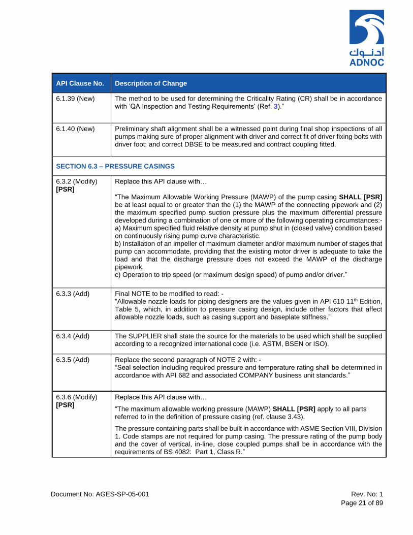
6.1.39 (New) The method to be used for determining the Criticality Rating (CR) shall be in accordance with ‘QA Inspection and Testing Requirements’ (Ref. 3).”
6.1.40 (New) Preliminary shaft alignment shall be a witnessed point during final shop inspections of all pumps making sure of proper alignment with driver and correct fit of driver fixing bolts with driver foot; and correct DBSE to be measured and contract coupling fitted.
SECTION 6.3 – PRESSURE CASINGS
6.3.2 (Modify) [PSR]
Replace this API clause with… “The Maximum Allowable Working Pressure (MAWP) of the pump casing SHALL [PSR] be at least equal to or greater than the (1) the MAWP of the connecting pipework and (2) the maximum specified pump suction pressure plus the maximum differential pressure developed during a combination of one or more of the following operating circumstances:- a) Maximum specified fluid relative density at pump shut in (closed valve) condition based on continuously rising pump curve characteristic. b) Installation of an impeller of maximum diameter and/or maximum number of stages that pump can accommodate, providing that the existing motor driver is adequate to take the load and that the discharge pressure does not exceed the MAWP of the discharge pipework. c) Operation to trip speed (or maximum design speed) of pump and/or driver.”
6.3.3 (Add) Final NOTE to be modified to read: - “Allowable nozzle loads for piping designers are the values given in API 610 11th Edition, Table 5, which, in addition to pressure casing design, include other factors that affect allowable nozzle loads, such as casing support and baseplate stiffness.”
6.3.4 (Add) The SUPPLIER shall state the source for the materials to be used which shall be supplied according to a recognized international code (i.e. ASTM, BSEN or ISO).
6.3.5 (Add) Replace the second paragraph of NOTE 2 with: - “Seal selection including required pressure and temperature rating shall be determined in accordance with API 682 and associated COMPANY business unit standards.”
6.3.6 (Modify) [PSR]
Replace this API clause with…
“The maximum allowable working pressure (MAWP) SHALL [PSR] apply to all parts referred to in the definition of pressure casing (ref. clause 3.43).
The pressure containing parts shall be built in accordance with ASME Section VIII, Division 1. Code stamps are not required for pump casing. The pressure rating of the pump body and the cover of vertical, in-line, close coupled pumps shall be in accordance with the requirements of BS 4082: Part 1, Class R.”

Document No: AGES-SP-05-001 Rev. No: 1
Page 22 of 89
API Clause No. Description of Change
6.3.7 (Add) SUPPLIER shall include a 3 mm corrosion minimum allowance for all pump casings. However, if a higher corrosion allowance is required, based on the required service life and operating conditions, the SUPPLIER shall include for and state the minimum required corrosion allowance in the proposal.
6.3.8 (Add) The inner casing of type BB5 pumps shall be axially split and volute type for abrasive service applications.
6.3.9 (Modify) Replace the last sentence with… “Pump selection shall be subject to the mandatory restrictions on pump type, MAWP and fluid constituents as specified by clause 4.2.2.9.”
6.3.10 (Add) The SUPPLIER shall use solid metal, metal-clad or confined and compression restricted, spiral wound metal or non-asbestos filled gaskets conforming to ASME B16.20 for design temperature over 177°C. O-rings shall not be used under these conditions. Gasket materials shall be selected in accordance with ISO 13709 API610 11th Edition Table H.1 and Annex G (Table G.3) of this standard.
6.3.11 (Modify) Modify this clause to state…. “Centerline – supported pump casings shall be used for all horizontal pumps.”
6.3.17 (New) The following holding down arrangements shall be applied: - a. Hold down bolt clearance holes in pump support baseplates shall be in accordance with ASME B18.2.8, clearance holes for bolts, screws and studs. b. Between bearings pumps shall have provisions for fitment of doweling pins at drive end supports only.
6.3.18 (New) The following machining tolerances shall apply: - a. Underside of horizontal pump casing support feet shall be machined flat and parallel to each other to within 0.04 mm/m vertical difference at each support point. b. Underside of vertically suspended pump heads shall be machined flat to within 0.05 mm.
6.3.19 (New) Vertical line shaft pumps shall have flanged bowls and column parts.
SECTION 6.4 – NOZZLES AND PRESSURE CASING CONNECTIONS
6.4.1.2 (Add) SUPPLIER shall provide support bracing for external connections (including valves where provided) as are required to ensure that the connection is not overloaded or subject to fatigue failure.
Document No: AGES-SP-05-001 Rev. No: 1
Page 23 of 89
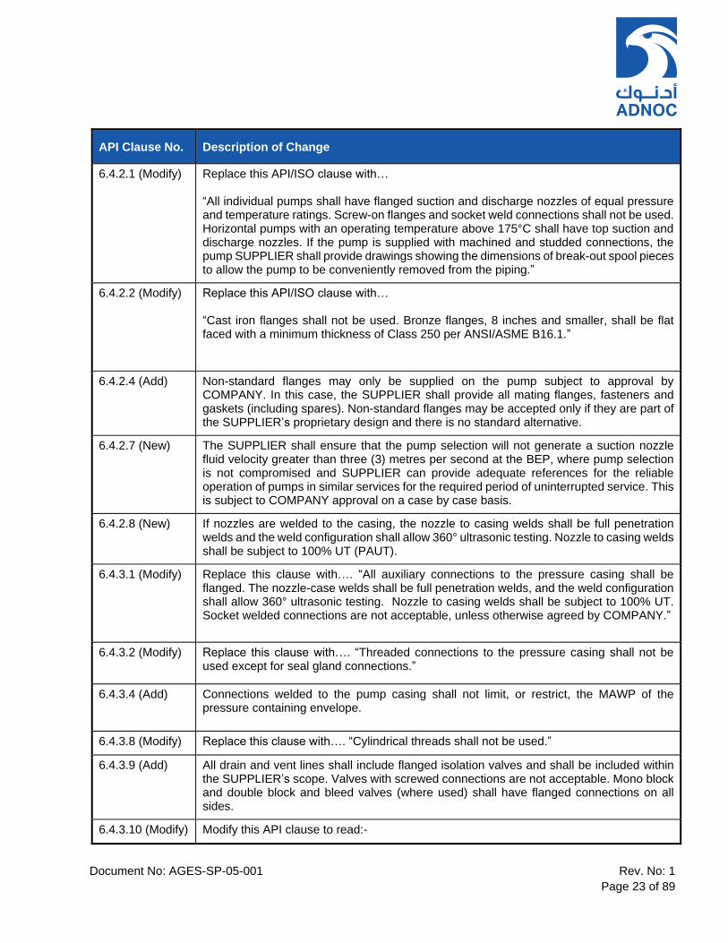
API Clause No. Description of Change
6.4.2.1 (Modify) Replace this API/ISO clause with… “All individual pumps shall have flanged suction and discharge nozzles of equal pressure and temperature ratings. Screw-on flanges and socket weld connections shall not be used. Horizontal pumps with an operating temperature above 175°C shall have top suction and discharge nozzles. If the pump is supplied with machined and studded connections, the pump SUPPLIER shall provide drawings showing the dimensions of break-out spool pieces to allow the pump to be conveniently removed from the piping.”
6.4.2.2 (Modify) Replace this API/ISO clause with… “Cast iron flanges shall not be used. Bronze flanges, 8 inches and smaller, shall be flat faced with a minimum thickness of Class 250 per ANSI/ASME B16.1.”
6.4.2.4 (Add) Non-standard flanges may only be supplied on the pump subject to approval by COMPANY. In this case, the SUPPLIER shall provide all mating flanges, fasteners and gaskets (including spares). Non-standard flanges may be accepted only if they are part of the SUPPLIER’s proprietary design and there is no standard alternative.
6.4.2.7 (New) The SUPPLIER shall ensure that the pump selection will not generate a suction nozzle fluid velocity greater than three (3) metres per second at the BEP, where pump selection is not compromised and SUPPLIER can provide adequate references for the reliable operation of pumps in similar services for the required period of uninterrupted service. This is subject to COMPANY approval on a case by case basis.
6.4.2.8 (New) If nozzles are welded to the casing, the nozzle to casing welds shall be full penetration welds and the weld configuration shall allow 360° ultrasonic testing. Nozzle to casing welds shall be subject to 100% UT (PAUT).
6.4.3.1 (Modify) Replace this clause with…. “All auxiliary connections to the pressure casing shall be flanged. The nozzle-case welds shall be full penetration welds, and the weld configuration shall allow 360° ultrasonic testing. Nozzle to casing welds shall be subject to 100% UT. Socket welded connections are not acceptable, unless otherwise agreed by COMPANY.”
6.4.3.2 (Modify) Replace this clause with…. “Threaded connections to the pressure casing shall not be used except for seal gland connections.”
6.4.3.4 (Add) Connections welded to the pump casing shall not limit, or restrict, the MAWP of the pressure containing envelope.
6.4.3.8 (Modify) Replace this clause with…. “Cylindrical threads shall not be used.”
6.4.3.9 (Add) All drain and vent lines shall include flanged isolation valves and shall be included within the SUPPLIER’s scope. Valves with screwed connections are not acceptable. Mono block and double block and bleed valves (where used) shall have flanged connections on all sides.
6.4.3.10 (Modify) Modify this API clause to read:-
Document No: AGES-SP-05-001 Rev. No: 1
Page 24 of 89
API Clause No. Description of Change
“Connections that are less than or equal to DN 50 (NPS 2) shall be gusseted. Piping shall be gusseted in two orthogonal planes to increase the rigidity of the piped connection in conformance to the following stipulations:
a. Gussets shall be made of: 1. Material matching the pressure casing and the piping. 2. Either flat bar with a cross section of at least 25 mm by 3 mm or round bar with a
diameter of at least 9 mm. b. Gusset design shall conform to Figure 20. c. Gussets shall be located at or near the connection end of the piping and fitted to the closest convenient location on the casing to provide maximum rigidity. d. Long width of gussets made with bar shall be perpendicular to the pipe and shall be located to avoid interference with the flange bolting or maintenance areas on the pump. e. Gusset welding shall conform to the fabrication specification in 6.12.3, including PWHT, if required, and the inspection requirements within Appendix 2 (Ref clause 8.2.2).” Flange welded to casing shall be rigid enough to sustain the allowable forces and moments without any distortion etc. for whole design life of the equipment. Gusseting shall require COMPANY approval.
6.4.3.11(Modify) Replace this API/ISO clause with…. “Openings in the pressure casing shall not be furnished unless they are essential. All auxiliary connections to pressure casings which are not permanently connected to piping shall include a RFWN flanged connection in accordance with clause 6.4.3.1 and fitted with a blind flange. Balance lines and their respective casing connections shall be flanged. Unions shall not be used.”
6.4.3.12 (Modify) Replace the first sentence with… “For high energy pumps only, auxiliary connections to the pressure casing may be machined and studded.”
6.4.3.14 (Add) The following requirements shall apply for pump venting and draining:- a. If a vent connection is required, vent piping shall terminate with a flange connection and isolation valve. Vent connections shall be at least DN 20 (NPS 3/4). b. Fluid passages within pumps (including auxiliary piping) shall be arranged for complete drainage. If this arrangement is not feasible (e.g. for horizontal multistage pumps), the SUPPLIER shall identify those specific areas within pump that cannot be completely drained. c. Drain piping shall be:-
1. Straight run only with no bends or elbows, terminating with a flanged isolation valve located within 150 mm of the casing.
2. At least DN 25 (NPS 1), with flanged connection to casing. 3. At least DN 50 (NPS 2), with flanged connection to casing for pump casings over
0.75 m3, hot oil pumps and pumps in fouling or dirty service. For larger pump casings and for heavy or viscous pumped fluids, the size of the drain connections shall be increased as required to enable complete draining of the pump casing.
4. Extended to edge of baseplate for pumps mounted on baseplates. d. For slurry services:
1. Drain and vent connections shall be at least DN 25 (NPS 1). 2. Isolation valves shall be ball type. 3. Drain piping shall be straight run only with no bends or elbows, terminating with a
flange located within 150 mm of the casing.

Document No: AGES-SP-05-001 Rev. No: 1
Page 25 of 89
API Clause No. Description of Change
4. If double volute construction results in an internal liquid trap, a drain hole shall be provided at low point of inner volute to allow complete drainage of volute section.
e. If drains are likely to block, piping design shall facilitate mechanical cleaning.
f. Pumps operating at temperatures greater than 260°C shall have rodding out drains and in this case, the following requirements apply:-
1. Drain shall come off the casing horizontally. 2. Drain piping shall be straight run only with no bends or elbows, terminating with a
flanged connection and mating blind flange located within 150 mm of the pump casing.
6.4.3.16 (New) Pressure gauge connections shall not be included on pump pressure casings.
SECTION 6.5 – EXTERNAL NOZZLE FORCES AND MOMENTS
6.5.1 (Modify) Replace the first sentence with… “The pump suction and discharge nozzles shall be designed to withstand TWICE the quoted values in Table 5. The values in Table 5 shall be taken to apply simultaneously to both suction and discharge nozzles in the worst case combination for each pump.”
SECTION 6.6 – ROTORS
6.6.1 (Modify) Replace the first sentence of this clause with…. “Unless otherwise specified, impellers shall be of fully enclosed type.”
6.6.2 (Modify) Replace the first sentence with… “Impellers shall be single piece castings or forged impellers. Fabricated impellers are subjected to COMPANY approval.”
6.6.3 (Add) On pumps with two or more stages, the radial position of each impeller on the shaft shall be staggered to avoid coincidence of pressure pulses at the entry to volutes and/or diffusers. Collets shall not be used in vertical pumps.
6.6.5 (Add) Cast iron (grey cast iron or nodular cast iron) shall not be used.
6.6.6 (Add) Shaft sleeves are required on all pumps. Shaft sleeves shall be hard faced where in contact with packing or dynamic secondary sealing element of a mechanical seal. Colmonoy 6 is an acceptable coating; alternative coatings shall be subject to agreement with COMPANY.
6.6.10 (Modify) Replace sub-clause (e) 1) with... “For areas to be observed by radial vibration probes, 25% of allowed peak to peak vibration amplitude or 6 µm (0,25 mil), whichever is less.”
6.6.11 (Modify) Replace second sentence with…… “The use of target rings is subject to COMPANY approval. If used, these shall be identified in the technical documentation.”

Document No: AGES-SP-05-001 Rev. No: 1
Page 26 of 89
API Clause No. Description of Change
6.6.15 (New) The SUPPLIER shall ensure that the following are considered in the pump design to prevent contact between impeller(s) and wear rings when stationary, during start up and under all operating conditions: - a. Rotor sag shall be:
1. Considered in the design clearances of impellers and seals. 2. No more than 75% of the design clearance.
NOTE: Pump rotor shall not be allowed to sag at start-up such as to cause impeller or wear ring contact. b. Static deflection of the shaft shall not be greater than the minimum radial internal clearances of the casing or rotor assembly. c. The use of welded or bi-metallic shafts are not acceptable.
6.6.16 (New) Shaft mounted cooling fans on BB2 and BB3 style pumps shall be mounted directly to pump shaft. Bolted or threaded shaft extensions shall not be used.
6.6.18 (New) Shafts and impellers shall not be plated for repair purposes. Repairs to rotating elements shall be completed in accordance with ‘QA Inspection and Testing Requirements’, (Ref. 3) and the proposed repair procedures subject to review and approval by COMPANY. Refer to amendment to clause 6.12.2.5 therein.
SECTION 6.7 – WEAR RINGS AND RUNNING CLEARANCES
6.7.1 (Add) If efficiency can be improved without compromising reliability, then: a. Wear rings made from alternative materials may be offered. b. Hard coatings may be offered. c. Running clearances and the alternative materials shall be subject to approval by COMPANY. NOTE: Wear ring materials are dependent on service. Options include hardened or high velocity oxygen fuel (HVOF) hard coated materials, such as tungsten carbide or Vespel, and Polyetheretherketone PEEK for abrasive services.
6.7.2 (Add) The stationary wear ring shall have a minimum hardness of 250 HB, except where otherwise specified. The stationary wear ring shall be the softer of the two wear rings.
6.7.3 (Modify) Replace the first sentence with …… “Renewable wear rings, if used, shall be held in place by a press fit with three axial screws or by tack welding in at least three places that are equally spaced. Add the following sentence to the end of clause… “Wear rings shall not be U-shaped in design.”
6.7.4 (Add) Add to sub-clause (a)… “Special wear ring constructions, including provisions for clean fluid flushing, may be considered for pumps handling erosive and abrasive liquids (Ref. clause 3.66 and 3.67), in which case the MANUFACTURER shall demonstrate reliability of the pump design for comparable duties.”

Document No: AGES-SP-05-001 Rev. No: 1
Page 27 of 89
API Clause No. Description of Change
6.7.4 (Add) Add the following new sub-clause…. “d) Inter-stage bushings for vertically suspended and multistage pumps handling hydrocarbons shall not be considered as bearings when determining clearances, but clearance shall be determined in accordance with the minimum diametrical clearances given in Table 6. Special attention shall be paid to running clearances in boiler feed water pumps with regard to hydraulic imbalance and rotor dynamic instability causing undesirable vibration or galling.”
6.7.5 (New) The SUPPLIER may use non-metallic wear rings (i.e. Vespel or equivalent) with lower clearances to increase efficiency, without detriment to the performance and integrity of the pump.
SECTION 6.8 – MECHANICAL SHAFT SEALS
General Seal Selection
Mechanical seal selection shall be in accordance with existing COMPANY business unit specifications. All related process safety considerations shall be taken into account when selecting mechanical seals.
6.8.1 (Add) The SUPPLIER shall be wholly responsible for the correct selection of the pump mechanical seal(s) and associated auxiliary equipment to suit the specified application. Full details of the proposed seal system including manufacturer, seal type, configuration and flushing plan shall be stated in the SUPPLIER’s bid. Irrespective of the specific arrangement, all pump seal chambers shall be sized to accommodate dual mechanical seals with auxiliary throttle device. Positive pressure shall be maintained in the pump seal chambers under all operating conditions.
6.8.2 (Modify) Replace this API clause with…. “The seal cartridge shall be removable without disturbing the driver, except for vertical pumps types OH5 and OH6.”
6.8.11 (Modify) Replace the words “If specified…” in this API clause with “If required for the pump service…”
SECTION 6.9 – DYNAMICS
6.9.1.4 (New) SUPPLIER information and input required to enable the COMPANY to perform an independent rotor-dynamic analysis shall be provided if requested. It is for COMPANY to decide if an independent rotordynamic analysis is required. This will typically be required for the following cases: - - Electric motor rated 500 kW or higher; - Electric induction motor with variable-frequency drive (VFD) rated 1000 kW or higher
6.9.2.1 (Add) The SUPPLIER shall perform a transient and steady state torsional critical speed analysis for all electric motor driven pumps for the following cases: -
1. Synchronous motor rated 500 kW or higher
Document No: AGES-SP-05-001 Rev. No: 1
Page 28 of 89
API Clause No. Description of Change
2. Electric motor with variable-frequency drive (VFD) rated 1000 kW or higher 3. If specified on the equipment datasheet
6.9.2.3 (Modify) Replace the first sentence with… “For Variable Frequency Drives (VFDs), a steady state damped response analysis shall be performed. Analysis shall consider resonant frequencies through 12 times line frequency.” Replace the third sentence with… “Modern VSDs, if performing properly, produce minor torsional vibration and may produce major torsional pulsations.”
6.9.2.4 (Modify) Replace the first sentence with… “SUPPLIER shall perform lateral analysis and train torsional analysis for vertical pumps (VS-6 type) when the length of pump (from pump bottom to discharge centre line) is higher than 2 metres.
6.9.2.5 (Add) Add the following to sub-clause (f)…. “This requires evaluation of n x slip for a synchronous motor. If the motor is synchronous, there is no slip. This would be part of a transient torsional analysis, and often the stresses for a transient torsional analysis are evaluated in the time domain. Excitations of torsional frequencies shall be considered based on drive characteristics and number of masses. The number of masses dictates the number of frequencies that can be calculated. NOTE: For a pump driven through a speed decreasing gearbox by a single wheel steam turbine, it is possible to describe the system by four masses and predict three torsional frequencies. Due account shall also be taken of excitations caused by gears with hunting tooth combinations and the number of teeth on both the wheel and the pinion shall be arranged such that the same teeth do not mesh on each revolution.”
6.9.2.10 (Modify) Modify first sentence to read…. “The SUPPLIER shall furnish a detailed report of the torsional analysis.” Add new sub-clause f) as follows: - “f) Acceptance requirements and list of frequencies evaluated.”
6.9.2.15 (New) The torsional analysis shall be performed in accordance with API RP 684. NOTE: In clause 6.9.2.10(e), the term “mode shape diagram” is not referring to machine speed in a geared system. Some diagrams show the following: -
1) Continuous (referenced speed mode shape plots). 2) Discontinuities at the gear element indicative of the change in angular
displacement at the gear for the two shafts.
Document No: AGES-SP-05-001 Rev. No: 1
Page 29 of 89
API Clause No. Description of Change
6.9.3.2 (Add) For vertical pumps with a flexible coupling, additional vibration readings shall be taken at the pump top bearing in the horizontal plane at 90 degrees to each other.
6.9.3.3 (Add) The plotted spectra shall be included with the pump test results.
6.9.3.9 (New) Pumps furnished with proximity probes shall also be fitted with key phasor probes.
SECTION 6.10 – BEARINGS AND BEARING HOUSINGS
6.10.1.1 (Add) The instrumentation and lubrication methods required for selected bearing arrangements shall be in accordance within - ‘Instrumentation and Condition Monitoring Requirements’ (Ref. 6)’ and ‘Lubrication System Design Requirements’ (Ref. 7). For instrumentation requirements refer to relevant COMPANY business unit Instrumentation and Control Standard for Machine Monitoring System (MMS).
6.10.1.2 (Add) When hydrodynamic thrust bearings are proposed, the following shall apply: a. Pump hydraulic design shall be such that the axial loads are unidirectional under all operating conditions. Thrust bearing shall be capable to withstand any transient thrust condition which may also occur. b. SUPPLIER shall submit in his bid, curves showing the variation of axial load with capacity (zero flow to EOC flow) for design internal clearances and two times design internal clearances. For variable speed units, similar curves for maximum and minimum continuous speeds shall be submitted.
6.10.1.3 (Modify) Third sentence shall read… “Cages shall be machined bronze or machined brass.”
6.10.1.4 (Modify) Second sentence shall read… “Cages shall be machined bronze or machined brass.”
6.10.1.6 (Modify) Replace first sentence with…. “Bearing system life (the calculated life of the combined system of bearings in the pump) shall be equivalent to at least 40 000 hours under continuous operation at rated conditions, and at least 25000 h at maximum radial and axial loads and rated speed.” Bearing System Life calculations shall be supplied for High Energy Pumps.
6.10.1.8 (Add) Add the following sub-clauses e) through to h). e) All bearings shall have metal rolling element retainers. f) Cylindrical roller bearings are the preferred radial bearing types. g) Roller bearings shall have the roller retaining rim on the inner race. h) Shielded or sealed bearings shall not be used.
6.10.1.9 (New) Hydrodynamic thrust bearings shall incorporate the necessary features for installation of condition monitoring instrumentation when specified. (Refer to clause 6.10.1.1 and 7.4.2.2).

Document No: AGES-SP-05-001 Rev. No: 1
Page 30 of 89
API Clause No. Description of Change
6.10.1.10 (New) The thrust bearing collar shall be replaceable and shall be positively locked to the shaft to prevent fretting.
6.10.1.11 (New) Bearings of pumps in molten sulphur pumps or other high temperature liquid service pumps (such as boiler feed water pumps) which are in close proximity to hot surfaces or hot piping, shall have special labyrinth type hot insulators. When forced lubrication is not present, bearing housings shall be cooled by a shaft mounted fan.
6.10.1.12 (New) For driver power ratings equal to or greater than 1000 kW, only hydrodynamic journal and or thrust bearings shall be used together with, forced lubrication to lubricate the bearings. For lower equipment power ratings, the bearing type and arrangement shall be in accordance with ‘Lubrication System Design Requirements’ (Ref. 7).
6.10.2.1 (Add) Bearing housings shall be of rigid design with a 360° mounting flange. For axially split casings, 180° mounting flange may be allowed.
6.10.2.2 (Add) The following additional requirements shall be applied: - a. Oilers and sight glasses shall have separate connections on sides of bearing boxes. Connections on bottom shall not be used. b. Piping connecting oiler and housing shall not have low points. c. Bearing housings shall have fill and valved drain openings and shaft seals, slingers, equalisers, vents or other devices required to prevent loss of lubricant. d. Constant level oilers shall be vented to bearing housing using stainless steel tubing. The requirement for permanent indication of oil level is met by a bullseye indicator. If steam turbine drives are used or if steam or water vapour is present in the area, it might be required to use an inert buffer gas to prevent ingress of water into bearing housing. e. The constant level oiler shall be located such that the oil level does not change as a result of oil movement caused by the action of the oil rings. If this is not possible the constant level oiler shall be located on the side of the bearing housing where the oil level is lower during the operation than when static.
6.10.2.4 (Modify) Replace first sentence with…. “Sufficient cooling, including an allowance for fouling, shall be provided to maintain oil and bearing temperatures as follows, based on the specified operating conditions and a design ambient temperature of 54°C”
6.10.2.4 (Modify) Modify sub-clause a) to read…. “For pressurized systems, the lube oil outlet temperature shall be less than 70°C and bearing metal temperatures (if bearing temperature sensors are supplied) shall be less than 95°C. During shop testing and under the most adverse specified operating conditions, the bearing oil temperature rise shall not exceed 28°C”
6.10.2.4 (Modify) Modify clause b) to read…. “For ring oiled or splash systems, the oil sump temperature shall be less than 82°C. During shop testing, sump oil temperature rise shall not exceed 40°C, and, if bearing temperature sensors are supplied, outer ring temperatures shall not exceed 95°C.
6.10.2.4 (Add) Add new sub-clause c), d) and e) as follows: -
Document No: AGES-SP-05-001 Rev. No: 1
Page 31 of 89
API Clause No. Description of Change
c) Lube oil temperature limits to be adjusted for 54°C site ambient conditions during shop performance testing. The following required limits shall apply to bearing lube oil temperature for both shop testing and site operation: - i. Maximum Operating Value = 95°C ii. Alarm = 105°C iii.Trip = 115°C d) If cooling is required to meet temperature limits for ring oiled and splash systems then the method of cooling shall be shaft mounted fans. Water cooling may be used subject to agreement by COMPANY. NOTE: Bearing cooling using cooling water jackets or sump coolers can lead to plugging and fouling if not properly designed and operated. e) Calculated heat loads and related assumptions shall be provided to COMPANY prior to testing. A temperature correction shall be applied for advantage or disadvantage from operating the shop test at different conditions as compared with that specified by COMPANY and guaranteed by SUPPLIER.
Table 10 Add the following additional notes d) and e) under “Table 10 - Bearing Selection”:- d. When the internal diameter of the rolling element bearing would exceed 150 mm, hydrodynamic bearings are required. e. For pumps with driver ratings over 1000 kW, hydrodynamic radial and thrust bearings are required.
6.10.2.5 (Add) If estuarine or seawater is specified for cooling, water velocities and small-bore piping connection sizes, as well as the materials to be used in the cooling system, shall be subject to agreement by COMPANY. Estuarine or seawater can result in fouling, corrosion/erosion, pitting corrosion and cracking issues, leading to loss of cooling water. When no cooling water is available on site, the SUPPLIER shall provide a closed loop cooling system complete with recirculation pump, air cooler(s) and all other required auxiliaries.
6.10.2.6 (Add) The following additional requirements shall apply where relevant: - 1. Steam-quench of the seal shall have magnetic bearing isolators. 2. For desert or dusty environments (wet sump pumps) a connection for continuous
dry air purge (plugged) shall be provided.
6.10.2.7 (Add) Oil mist systems are acceptable only for COMPANY refinery applications. Refer to ‘Business Unit Specific Requirements’ (Ref. 5) for Refinery Business Unit application specific requirements relating to Oil Mist Lubrication Systems.

Document No: AGES-SP-05-001 Rev. No: 1
Page 32 of 89
API Clause No. Description of Change
6.10.2.10 (Modify)
Modify to read… “Bearing housing shall have 25 mm (1 in) diameter flat surface with M8 x 1,25 (1/4 x 28) threaded hole for permanently mounting vibration transducers as shown in Figures 31 through to 33. For instrumentation requirements refer to ‘Instrumentation and Condition Monitoring Requirements (Ref. 6).
6.10.2.11 (Modify)
Replace this API clause with… “Where permanently installed vibration probes are not provided, a flat surface at least 25 mm (1 in) in diameter shall be supplied on the top of each bearing housing for the location of portable magnetic-based vibration-measuring equipment.”
SECTION 6.11 – LUBRICATION
6.11.1 (Add) The methods of lubrication required for selected bearing arrangements and driver power ratings shall be in accordance with ‘Lubrication System Design Requirements’ (Ref. 7). The oil viscosity grade and nominal oil capacity shall be stated on the pump datasheets. ADNOC mineral oils shall be used and equivalent oils shall be mentioned in the Installation, Operation and Maintenance (IOM) manuals.
6.11.3 (Add) Purge oil mist systems are acceptable only for COMPANY Refinery Applications. Refer to Business Unit Specific Requirements (Ref. 6) relating to Oil Mist Lubrication Systems.
6.11.4 (Modify) Replace this API clause with… “Grease lubrication shall not be used except where permitted by ‘OPTION A’ as defined within ‘Lubrication System Design Requirements’ (Ref. 7). However, when the pump is supplied with forced lubrication, this shall also be extended to driver.”
6.11.5 (New) For ring oil lubricated sleeve bearings without a circulating system, the following shall be attached to the bottom of the bearing housing in the order indicated: -
1. Bronze gate valve. 2. Clear plastic sight indicator. 3. Petcock.
Oil rings shall be grooved on the inside diameter for enhanced oil circulation.
6.11.6 (New) Use and design of oil flingers shall be subject to approval by COMPANY. NOTE: Design verification of proper attachment to prevent movement of flinger is important for proper operation of oil flingers.
SECTION 6.12 – MATERIALS
6.12.1.1 (Modify) Replace first and second sentence with… “The selection of pump component materials shall be in accordance with Annex G and Annex P of this Specification, which supplement API 610 11th Edition, Annex H.”
Document No: AGES-SP-05-001 Rev. No: 1
Page 33 of 89
API Clause No. Description of Change
6.12.1.2 (Modify) Replace the third sentence with… “Materials for pump parts shall be in accordance with Annex G, Annex H and Annex P unless otherwise specified on the equipment datasheets.”
6.12.1.6 (Modify) Modify this API clause to read…. “Materials for pump parts shall be in accordance with Annex G, Annex H and Annex P unless otherwise specified on the equipment datasheets.”
6.12.1.12 (Add) All materials for components exposed to hydrogen sulfide in concentrations exceeding 50 ppm or exceeding the limits prescribed by NACE Standard MR0175 / ISO 15156 or MR0103 / ISO 17945 as applicable shall conform to the requirements of NACE Standard MR0175 / ISO 15156 or MR0103 / ISO 17945 as applicable as well as project specifications. Renewable wear rings that, for proper pump performance must be hardened above the limits of NACE Standard MR0175 / ISO 15156 or MR0103 / ISO 17945 are acceptable. When approved by the COMPANY, in lieu of furnishing renewable wear rings, wear surfaces may be hardened by the application of a suitable coating. All external bolting on the casing and seal glands shall also conform to the above requirements even when NACE Standard ISO 15156 or ISO 17945 restricts the requirement to enclosed bolting. Pumps handling seawater or brine above 40°C contaminated with oil and H2S shall be fabricated in super duplex stainless steel or other suitable corrosion resistant material.
6.12.1.12.7 (New)
All external bolting on the pump casing and seal glands shall also conform to the requirements of NACE Standard ISO 15156 or ISO 17945 as applicable, where the pump is used for sour service.
6.12.1.15 (Modify)
Replace the API clause with…. “Bearing housing(s), load-carrying bearing housing covers and brackets between the pump casing or heads and the bearing housing(s) shall be steel except for pumps constructed in accordance with Table H.1, Classes I-1 or I-2.Driver supports for vertical pumps that utilize thrust bearings in the driver to support the shaft shall be steel.”
6.12.4.1 (Add) The minimum temperature for which the equipment has to be suitable (under any operating or upset conditions) shall be specified on the equipment datasheet. If the specified minimum temperature is 0°C (32 °F) or less, then the materials of construction for pressure-containing parts proposed by the SUPPLIER shall be subject to approval by COMPANY.
SECTION 6.13 – NAMEPLATES AND ROTATION ARROWS
6.13.2 (Modify) Replace the first sentence with: - “The nameplate shall be stamped with the following information. All text shall be in the English language and the numerical data shall be in SI units.” Add the following new sub-clauses: - k. Year of manufacture l. Purchaser’s order number
Document No: AGES-SP-05-001 Rev. No: 1
Page 34 of 89
Table 9 – API 610 Technical Amendments: Section 7 – Accessories
API Clause No. Description of Change
SECTION 7 – ACCESSORIES
SECTION 7.1 – DRIVERS
7.1.1 (Add) Drivers with rolling element bearings shall be mounted on baseplate with driver coupling hub installed. Drivers with sleeve bearings shall be blocked and shipped with coupling spacer loose. The SUPPLIER shall specify the starting conditions and starting method for the pump, considering the connecting pipework sizes, service, installation arrangement, and driver constraints such as starting with open/closed discharge valve or with minimum flow recycle valve open.
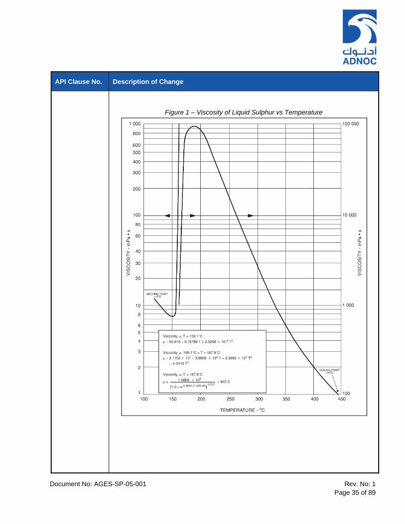
7.1.2 (Add) Where the equipment datasheet specifies a range for the liquid specific gravity, viscosities, the pump selection shall be based on the following: - a. Differential head shall be calculated based on minimum specific gravity b. Pump power shall be calculated based on maximum specific gravity c. Design pressure shall be calculated based on maximum specific gravity. d. Viscosity correction factors as required shall be considered for driver selection. Viscosity correction factors for sulphur pumps shall be estimated after considering heat gain in pump, sleeves, bearings, seals etc. and H2S content in sulphur while determining the viscosity of sulphur using Figure 1 below:-
Document No: AGES-SP-05-001 Rev. No: 1
Page 35 of 89
API Clause No. Description of Change
Figure 1 – Viscosity of Liquid Sulphur vs Temperature

Document No: AGES-SP-05-001 Rev. No: 1
Page 36 of 89
API Clause No. Description of Change
Figure 2 – Effects of Hydrogen Sulphide on Viscosity of Molten Sulphur
7.1.3 (Modify) Replace this API clause with…. “Drive train equipment feet shall have vertical jackscrews. Lifting eyes shall be provided to allow the controlled manual handling of drivers during alignment procedures to avoid injury to technicians.”
7.1.4 (Modify) Delete first three sentences and replace with… “The minimum required motor nameplate rating (without service factor) shall be the greater of: - a) The percentage of pump shaft power at specified rated conditions given in Table 12. b) Shaft power during operation with water when using the furnished impeller at rated speed and at minimum continuous stable flow. c) 0.37 kW. d) For motor driven, vertical close-coupled pumps (OH5), the motor rating shall be sufficient to permit shop testing with water at the rated conditions.

Document No: AGES-SP-05-001 Rev. No: 1
Page 37 of 89
API Clause No. Description of Change
e) Shaft power at end of curve (EOC) x 1.1 when using the rated impeller at rated speed and NORMAL fluid specific gravity (all applications except for onshore business unit). f) Shaft power at end of curve (EOC) x 1.1 when using the maximum impeller diameter at rated speed and NORMAL fluid specific gravity (onshore business unit applications only). g) Shaft power at end of curve (EOC) when using the rated impeller diameter at rated speed and MAXIMUM fluid specific gravity NOTE 1: Viscosity correction factors as required shall be considered for driver selection where applicable. NOTE 2: If standard performance test requirements would lead to unnecessary oversizing of the motor driver, an alternative proposal shall be submitted to the COMPANY for approval.
7.1.5 (Add) Electric motor drivers shall be designed and selected in accordance with COMPANY business unit standard(s) for electric motors as listed in ’ General Technical and Contractual Requirements for Rotating Equipment (Ref. 2).
7.1.6 (Add) The centrifugal pump driver shall be sized in accordance with the requirements of clause 7.1.4. The motor shall be suitable for starting the pump with open discharge valve and when required by Auto start / DCS start. For pump “auto-start”, the motor shall be capable of accelerating the pump to rated speed at 80 % voltage against an open discharge valve. The pump SUPPLIER shall submit pump speed torque curve superimposed on driver speed torque curve as defined within ‘Information Requirements’ (Ref. 4).
7.1.7 (Add) Electric motors with thrust bearings (OH4) design shall be designed to carry double the maximum up-thrust and double the maximum down-thrust that the pump may develop during operation at the rated conditions and during starting, stopping or during shop test on water. The maximum thrust load shall be calculated at twice the internal clearances specified. The pump SUPPLIER shall specify the maximum up-thrust to the electric motor SUPPLIER to permit correct selection of the electric motor driver.
7.1.8 (Modify) Replace sub-clause a) with.… “Rolling element bearings shall be selected to give a basic rating life, in accordance with ISO 281, equivalent to at least 50,000 h for IEC motors (or 100,000 h for IEEE motors) with continuous operation at pump rated conditions.” Add the following to sub-clause b): “The pump Manufacturer/SUPPLIER shall supply thrust data to the electric motor Manufacturer/SUPPLIER and approve the selection of bearings.” Replace sub-clause (e) with …“Thrust bearings shall be designed to carry double the maximum up-thrust and double the maximum down-thrust the pump can develop while starting, stopping or operating at any capacity, or while being tested with water if applicable (OH5).”
7.1.9 (Add) Steam turbine drivers shall be continuously rated to deliver at least 110% of the shaft power required (at pump rated conditions) when using the furnished impeller at the maximum fluid specific gravity and while the steam turbine is operating at the minimum
Document No: AGES-SP-05-001 Rev. No: 1
Page 38 of 89
API Clause No. Description of Change
inlet pressure / maximum outlet backpressure steam conditions with no external restriction on flow demand.”
7.1.10 (Modify) Replace this API clause with…..“Speed increasing or decreasing gear units shall be supplied in accordance with COMPANY Standard for API 613 / API 677 Gearboxes as referenced within ‘General Technical and Contractual Requirements’ (Ref. 2).
7.1.11 (New) If diesel/gas engines are specified as drivers, these shall be selected to have a site base load rating (per ISO 3977) of at least 110% of the greatest power (including all losses such as gear, fluid coupling, or other losses, as applicable) required. This shall be applicable for any of the specified operating conditions at corresponding ambient air temperatures and with design inlet and exhaust system losses. Refer to relevant COMPANY business unit standards as referenced within ‘General Technical and Contractual Requirements’ (Ref. 2), for further details on driver sizing margins.
7.1.12 (New) Natural gas and diesel engine drivers shall be supplied in accordance with COMPANY Business Unit Standard for Reciprocating Internal Combustion Engines as referenced within ‘General Technical and Contractual Requirements’ (Ref. 2).
7.1.13 (New) When operating in electrical classification areas of Division 1 or 2, internal combustion engines shall comply with BS EN 1834-1.
SECTION 7.2 – COUPLINGS AND GUARDS
7.2.2 (Add) Flexible element couplings shall be used. Couplings shall have a minimum service factor of 1.5 based on motor nameplate power. Failure of flexible element shall disengage the drive to the pump. Couplings shall be non-sparking type.
7.2.2 (Modify) Modify sub-clause f) to read… “f) Couplings operating at speeds in excess of 3500 rpm and rated over 746 kW shall require component balancing and assembly balance check. The assembled coupling shall meet AGMA class 9 requirement. Key, keyways and assembly/interference fits shall conform to AGMA 9002 class.”
7.2.2 (Add) Add new sub-clause g) as follows… “g) If the pumping temperature is greater than 200°C, spacers shall have a minimum length of 180 mm to provide greater tolerance for misalignment. Spacer length shall be minimum 450mm if driver rating is above 1000kW. Pumps in hot service application shall be hot aligned to compensate for thermal growth, thus reducing misalignment.”
7.2.2 (Add) Add new sub-clause h) as follows… “h) Stepped keys shall be supplied when the shaft keyway extends beyond the coupling hub.”
7.2.2 (Add) Add new sub-clause i) as follows… i) Couplings shall meet the following additional requirements: -
1. Coupling hubs and spacers shall be steel with a permanent corrosion resistant coating. Permanent coatings such as zinc phosphate prevent surface corrosion of components.

Document No: AGES-SP-05-001 Rev. No: 1
Page 39 of 89
API Clause No. Description of Change
2. Hubs shall be removable. ii) Shafts over 75 mm diameter, or pumps with drivers rated over 750 kW shall be tapered
and have hydraulically mounted coupling hubs.
7.2.2 (Add) Add new sub-clause j) as follows… “j) Coupling spacer nominal length shall: -
1. Be at least 150 mm, except where otherwise required by clause 7.2.2(g) 2. Be at least 300 mm, for pumps with an operating temperature of 260°C or
greater 3. Be standard length within the above requirements
For example, if the selected SUPPLIER does not offer a 150 mm spacer as standard, the next longer length shall be supplied to meet the requirement. The SUPPLIER shall allow for conversions from single to double seals when selecting spacer length, if specified on the equipment datasheets. Changes from single to dual seals require additional length.”
7.2.3 (Modify) Delete the words “If specified” in this API clause.
7.2.4 (Add) Applications exceeding 3600 rpm or greater than 1000 kW shall utilise API 671 special purpose couplings.
7.2.5 (Add) The following requirements shall apply: - a. Design shall account for axial float and thermal growth. b. Design data shall be provided. c. Key shall be stepped and fill the entire shaft slot, or exposed key volume shall equal volume of unfilled keyway.
7.2.7 (Delete) Delete this API clause.
7.2.8 (Add) The following requirements shall also apply: - a. Dry disc coupling hubs with cylindrical bores shall be installed so that hub mating flange face is perpendicular with driven shaft longitudinal axis. b. For the pump only, cylindrical fit hubs less than 63 mm in diameter shall be line-on- line to 0.01 mm tight fit to the shaft. A set screw shall be provided over the key. c. Driver coupling hubs shall be interference fit in conformance to SUPPLIER's recommendations. d. Contact blue check and tape lifts shall be conducted for tapered fit couplings. e. Required amount of pull up for tapered fit couplings shall be defined and documented. f. Driver coupling hub shall be measured for TIR (Total Indicator Runout) in conformance to 8.2.1.6.f.
7.2.10 (Add) The following requirements shall also apply:- a. High energy pumps shall use keyless, hydraulically fitted coupling hubs. b. Keyless, hydraulically fitted coupling hubs shall use an O-ring to contain the hydraulic pressure. c. A metal to metal interference fit alone to contain the hydraulic pressure shall not be used.
7.2.11 (Modify) Replace the words “If specified” in the first sentence with “If required by SUPPLIER”.
Document No: AGES-SP-05-001 Rev. No: 1
Page 40 of 89
API Clause No. Description of Change
At the end of the third sentence add… “However, clamping devices may only be used as a last option and their use is subject to COMPANY review and approval”.
7.2.13 (Add) Add the following new sub-clause e): - e) Coupling guards shall: -
1. Be lightweight, brass non-sparking type material, except for ammonia service where aluminium (highest purity) may be used.
2. Be constructed from a certified spark-resistant material (see clause 6.10.2.6 note). Preferred design shall be horseshoe type and bolted to baseplate.
3. Limit effects of windage to maintain coupling guard temperature to less than 70°C.
7.2.14 (Delete) Delete this API clause. Refer to clause 7.2.13.
7.2.16 (New) If a solid shaft motor driver does not have non-reverse ratchet, coupling hubs shall be of a locked type design that will not unscrew if motor is started in the reverse rotation.
SECTION 7.3 – BASEPLATES
7.3.1 [Add] Structural baseplate materials shall be as specified within COMPANY ‘Structural Design Basis’ as referenced within ‘General Technical and Contractual Requirements’ (Ref. 2).
7.3.2 (Add) Baseplates shall extend under the full length and width of pump, driver and auxiliary equipment so that mounted equipment does not overhang the baseplate edge. For larger HV/MV motors, the motor terminal box may extend outside the confines of the baseplate, subject to COMPANY approval. The following requirements shall apply:- a. Baseplate dimensions shall be such that there is no overhang of mounted equipment containing liquids including motors with oil lubricated bearings. b. Baseplates shall have a raised lip around the upper edge. c. Baseplates shall not have drain rims around the lower edge.
7.3.5 (Add) To provide satisfactory mounting arrangements each pump shall meet the following requirements as a minimum:-
g. a. Soleplates shall be steel plates with a minimum thickness of 40mm, or greater if required to transmit expected loads from equipment to foundation. Corners of soleplates shall be rounded. b. Equipment mounting pedestals shall be fabricated box design. Pipe columns with rails or plates shall not be used. c. Baseplate equipment mounting pads shall be level within 0.08 mm/m. d. Levelness requirements shall be met without clamping down baseplate and after welding to baseplate has been completed
h. e) Mounting pads for driver shall provide a minimum vertical clearance of 50 mm beneath the driver at each end to allow insertion of a vertical alignment jack.
7.3.6 (Add) To achieve satisfactory levelling, each pump shall meet the specified limits within API 686 and the following additional requirements as a minimum:-
Document No: AGES-SP-05-001 Rev. No: 1
Page 41 of 89
API Clause No. Description of Change
a. Levelness requirements shall be met without clamping down baseplate and after welding to baseplate has been completed. b. Machined pad elevations shall require installation of no more than 6 mm shim pack under each component once final alignment is achieved. Vertical placement of equipment shall be set to compensate for operating temperatures. c. Pumps shall have a tag that shows degree of misalignment from manufacture at factory. d. In pump motor machine trains, no shims shall be located under pump feet. In pump gearbox motor trains, no shims shall be under gearbox feet. e. Shims shall:
1. Straddle the hold down bolts. 2. Not be tapered, stepped, or peelable.
f. No more than three shims per foot shall be supplied to achieve final alignment in SUPPLIER shop. g. Shim materials for pumps in marine environment service shall be at least 316L SS.
7.3.8 (Add) Mounting holes in the baseplate shall not penetrate into the grouted areas. This shall include holes for: a. Equipment anchoring. b. Coupling guard mounting. c. Auxiliary equipment mounted on the baseplate.
7.3.9 (Modify) Modify this API clause to read… “To facilitate grouting, cross-members shall be at least 40 mm shorter than baseplate depth.”
7.3.10 (Modify) Replace this API clause with … “The following minimum requirements shall apply for baseplates:-
1. Baseplates shall be designed for installation with only a seal pour of grout on the lower flange.
2. Baseplates shall be designed to prevent liquid accumulation inside. 3. Where equipment is mounted on concrete foundations, epoxy grout shall be
applied only for pumps with MV/HV motors or unless specifically required by SUPPLIER. Other pumps shall be installed with cement grout.
4. Pumps mounted on structures / platforms and for all offshore applications: Non-grouted irrespective of rating.
The following specific requirements shall also apply:-
i. Grout – Type of grout shall be as per relevant COMPANY Business Unit Standards unless otherwise required/specified by SUPPLIER.
ii. Anchor Bolt – The design of anchor bolts shall be as per relevant COMPANY Business Unit Standards referred to in the Purchase Order. The scope of supply for anchor bolts shall be defined within the Purchase Order.
iii. Base Frame – The design of the base frame shall be as per COMPANY Civil and Structural design specifications, taking into account all applicable design loads including static, dynamic, test, wind and seismic loads. The baseplate design shall also take into account:-
a) The type of supports to be provided (e.g. RCC foundation or Steel Structure). b) The required elevation of underside of base frame with respect to the specified
project datum.

Document No: AGES-SP-05-001 Rev. No: 1
Page 42 of 89
API Clause No. Description of Change
iv. Foundation / Sub-Structure Design Data – The SUPPLIER shall provide all required data to enable design of foundation or supporting structure by EPC CONTRACTOR. This shall include:-
a) All foundation loads imposed by the equipment for all relevant load cases including dry, operating, test, wind, seismic, static and dynamic load cases including transient loads imposed during start up and shutdown and shall clearly indicate design code and design parameters considered.
b) General Arrangement Drawing and Foundation Plan identifying location and size of support points and holding down / anchor bolts details / locations.
c) Maximum allowable vibration amplitude and velocity limits at baseplate level.
Refer to ‘General Technical and Contractual Requirements for Rotating Equipment’ (Ref. 2) for applicable COMPANY business unit standards relating to Civil and Structural design requirements.
7.3.12 (Add) Standard coating is inorganic zinc. This coating does not provide a bond strength that is as high as epoxy primers. The SUPPLIER may use epoxy primers instead of inorganic zinc subject to agreement by COMPANY.
7.3.13 (Modify) Replace the API clause with… “The following minimum requirements shall apply for pump baseplates:- a. Baseplate and pedestal support assembly shall be as rigid as required to be mounted without grouting. b. Baseplates in offshore applications:
1. Pump baseplates shall be as rigid as required to be welded to the structural support steel of the deck without distorting the equipment mounting surfaces. The SUPPLIER shall design the baseplate to limit the maximum specified deflection(s) in accordance with COMPANY business unit structural design specifications.
2. Structural cross members shall: a) Be full depth such that members are in the same plane if looking at the bottom of baseplate. b) Not penetrate the bottom plane of the baseplate that is coincident with main support beams.
3. Resonance frequency of the baseplate shall not be coincident with harmonic of pump running speeds as specified in the datasheets.
4. Two (2) earthing bosses are to be provided with each assembled pump and welded to diagonally opposite corners of the pump fabricated baseplate.
7.3.17 Replace first sentence of clause with the following…. “Transverse and axial positioning jackscrews shall be provided for drive train components which have a mass greater than 100 kg to facilitate transverse horizontal and longitudinal adjustments.”
7.3.20 (Modify) Replace this ISO/API clause with… “To minimize misalignment of the pump and driver shafts due to piping load effects, the pump and its baseplate shall be constructed with sufficient structural stiffness to limit displacement of the pump shaft at the drive end of the shaft or at the register fit of the coupling hub to the values shown in API 610 11th Edition, Table 13. These values are the acceptance criteria for the nozzle load test in 7.3.21. The stiffness of the baseplate shall be verified at the SUPPLIER’s works. It is also noted that thermal growth, piping fabrication errors, and alignment error all contribute to the actual deflection values achieved in the field. For horizontal pumps, adherence to TWICE the

Document No: AGES-SP-05-001 Rev. No: 1
Page 43 of 89
API Clause No. Description of Change
nozzle load values stated in Table 5 shall limit the total deflection at the pump and drive shaft ends to approximately 250 µm. This shall take precedence over the maximum displacement limits specified within Annex F, clause F.1.2.
Refer to ‘QA Inspection and Testing Requirements’ (Ref. 3) for level of inspection required by COMPANY and to ‘Information Requirements’ (Ref. 4) for details of information to be submitted by SUPPLIER.
7.3.21 (Modify) Replace this ISO/API clause with… “The SUPPLIER shall test to demonstrate that the pump and its baseplate assembly, whilst anchored at the supports, are in full compliance with clause 7.3.20. The stiffness of the baseplate shall be verified at the SUPPLIER’s works to ensure that the deflection of the baseframe when fully supported on its mountings does not exceed L/500 or SUPPLIER imposed limits whichever is less.
Refer to ‘QA Inspection and Testing Requirements’ (Ref. 3) for level of inspection required by COMPANY and to ‘Information Requirements’ (Ref. 4) for details of information to be submitted by SUPPLIER.
The maximum deflection of the baseplate shall be verified whilst the pump casing shall be subjected to moments MYc and MZc applied to either nozzle, but not both, such that the corresponding shaft displacements can be measured and recorded. MYc and MZc shall not be applied simultaneously to either nozzle. The shaft displacement measurements shall be absolute (not relative to the baseplate).
For record purposes, the SUPPLIER’s test data shall include a schematic drawing of test set-up, the calculated moment loads (MYc and MZc), and the applied moment loads and their corresponding displacements at the drive end of the pump shaft.
7.3.22 (New) The following requirements shall apply to mounting bolts supplied with the pump(s):- a. Mounting bolts shall bolt into drilled and tapped baseplates. Bolts shall not extend into pedestal cavity. b. Through-bolting shall not be used. c. Bolt holes shall be accurately located such that equipment is not bolt bound once aligned. d. Bolt hole location shall be based on motor rotor at magnetic centre.
7.3.23 (New) The following requirements shall apply to vertical in-line pumps:- a. Vertical inline pumps shall have a rigid mounting or soleplate bolted to pump casing. Requirements applicable to soleplate, as detailed herein, shall apply.
b. Bottom of pump and top of soleplate shall be machined flat within 0.05 mm.
SECTION 7.4 – INSTRUMENTATION
7.4.1 (Add) The plant Instrumentation and Control philosophy shall be as per COMPANY Process Control System Specification, Fire & Gas System Specification and Emergency Shutdown (SIS) Specification. Refer to ‘General Technical and Contractual Requirements for Rotating Equipment’ (Ref. 2) for details of applicable specifications.

Document No: AGES-SP-05-001 Rev. No: 1
Page 44 of 89
API Clause No. Description of Change
7.4.1.1 (New) The specific requirements for Package Instrumentation and Controls are detailed within the relevant COMPANY business unit Package Instrumentation Standard(s).
7.4.1.3 (New) A Local Gauge Board shall be provided by the SUPPLIER on the skid for mounting all local instrumentation such as Gauges and Transmitters. All pressure indicators shall read in barg and all temperature indicators shall read in °C. Transmitters shall include local indication.
7.4.2.1 (Modify) Replace this API clause with…. “For details of required bearing instrumentation refer to ‘Instrumentation and Condition Monitoring Requirements’ (Ref. 6).
7.4.2.2 (Delete) Delete this API clause.
7.4.2.3 (Delete) Delete this API clause.
7.4.2.4 (Delete) Delete this API clause.
7.4.2.5 (New) The following requirements shall apply to instrumentation used for condition monitoring:-
1. For between-bearing pumps, vibration (proximity) probes and holders shall be provided by the SUPPLIER in accordance with COMPANY nominated manufacturer. 2. Radial probe holders shall be stainless steel. 3. Extension cables shall be armoured. 4. Cables shall not be run in conduits. 5. Cables should be run in a neat and tidy manner and suitably supported. 6. Junction boxes shall be mounted on the edge of the skid. 7. Junction box locations shall be subject to the approval of the COMPANY
7.4.2.6 (New) Overload protection shall be configured and provided by the CONTRACTOR on all Sulphur pumps, set to trip the machine if the pump is not rotating due to Sulphur solidification (higher current). For VFD motor driven pumps, trip speed shall be 110% of rated speed.
7.4.3 (New) For high energy pumps the responsibility for providing monitoring instrumentation shall be as follows:- a. Monitor pump pressures, temperatures, and flow. Instrumentation required for monitoring of pump pressures, temperatures, and flow will be supplied and installed by EPC CONTRACTOR where shown on the Project P&ID’s. b. Detect seal leakage. Instrumentation required for bearing vibration and temperature monitoring and seal system leakage detection including interconnecting cables and wiring to skid edge mounted junction boxes shall be supplied and installed by pump SUPPLIER. The EPC CONTRACTOR shall provide the necessary interconnecting instrument cabling between SUPPLIER’s skid mounted field junction boxes and the DCS.
7.4.4 (New) Local control panels shall be provided ONLY where monitoring and control of equipment during plant normal operation and start up/shut down cannot be performed remotely by

Document No: AGES-SP-05-001 Rev. No: 1
Page 45 of 89
API Clause No. Description of Change
plant DCS or ICSS. If provided, local control panel(s) shall meet the following requirements:- a. Local Control Panel construction shall be Stainless Steel. b. Local Control Panel location is subject to review by COMPANY. c. Instruments shall be suitable for outdoor site conditions. However, local control panels shall be constructed with overhead roof and lateral shield for protection from direct sun exposure. d. All instrument signal interfaces shall be compatible with the plant control system(s) and are as detailed within are detailed within COMPANY business unit Package Instrumentation Standard(s). e. Instruments shall be suitable for installation in the hazardous area as specified on the equipment datasheets.
SECTION 7.5 – PIPING AND APPURTENANCES
7.5.1.1 (Add) Pump casing drains shall have a short stub to the first flange, no longer than 150 mm and preferably without any bends. The drain line after the first flange shall be supported between the pump and the edge of the baseplate.
7.5.1.2 (Modify) Replace the last sentence by…. “Piping for the pumped fluid and auxiliary systems shall be in accordance with ASME B31.3 for process piping, or ASME B31.1 for power piping. All auxiliary piping within the pump package shall be provided in Stainless Steel 316/L as a minimum and fabricated/installed in accordance with ASME B31.3. The SUPPLIER shall confirm compliance with these international Standards in their proposal. The SUPPLIER shall submit his Piping Specifications for evaluation. Valves furnished by the SUPPLIER shall be of the appropriate type and shall be suitable for the relevant piping class pressure/temperature rating specified by ASME. Pressure-temperature ratings for 600mm (24 inches NPS) and smaller carbon steel, ferritic alloy steel, and austenitic stainless steel flanges and valves are based on the requirements of ASME B16.5. For flanges of 650mm (26 inches NPS) and larger, ASME B16.47, Series A / MSS SP 44 shall be used for design and Pressure-Temperature Ratings. All openings shall be provided with metal tags to identify their purpose or service. Insulation shall be provided on pipework and equipment in accordance with ‘General Technical and Contractual Requirements’ (Ref. 2).
7.5.1.3 (Modify) Replace second sentence with…. “This includes the following items:- 1. Auxiliary piping on vertical pumps. 2. Piping mounted to SUPPLIER mounted auxiliary equipment.
Auxiliary piping may be removed for shipment if necessary. If removed for shipment, piping shall be tagged for reassembly and shipped with the pump.
Document No: AGES-SP-05-001 Rev. No: 1
Page 46 of 89
API Clause No. Description of Change
To avoid damage to pump components, some parts may be shipped separately, subject to agreement with COMPANY.”
7.5.1.4 (Add) For all vertical pumps, auxiliary equipment forming part of the seal support system e.g. buffer/barrier fluid reservoirs, heat exchanger and/or accumulator shall be mounted on a separate common baseplate adjacent to the pump. The SUPPLIER shall provide all interconnecting piping spools for connection between the seal system and the pump assembly. For all horizontal pumps, the complete seal system shall (where possible) be mounted on the pump baseplate. L shaped baseplates to accommodate seal system(s) are not acceptable. If the seal system dimensions mean that the size of the pump baseplate would be impractical, a separately mounted seal system near the pump baseplate may be provided subject to agreement by COMPANY. In this event, the SUPPLIER shall provide all interconnecting piping spools between the pump seal assembly and seal support system and shall be responsible for design and for determining sizing and lengths of all interconnecting seal piping. In all cases the SUPPLIER shall be responsible to ensure that the seal system and interconnecting pipework design shall permit the necessary barrier/buffer fluid circulation rates based on the specified pump operating conditions whilst allowing for seal system pipework pressure drops.
7.5.1.5 (Add) Auxiliary piping shall terminate with a flange at the edge of the baseplate.
7.5.1.6 (Modify) Delete the words “If specified” at the beginning of this clause and add the following:-
“Piping systems shall satisfy the following requirements:- 1. Piping fabrication shall be by welding or bending. 2. Flanged joints and removeable spool pieces shall be provided where disassembly is necessary to permit equipment maintenance and/or removal. 3. The size of each piping system shall be a minimum of ¾”.
4. Seal plan system shall include piping in accordance with ASME B.31.3. Tubing and tube fittings are acceptable only for connection to mechanical seal cartridge or to stuffing box.”
7.5.1.7 (Modify) Modify 2nd sentence to read, “Unless otherwise specified, flange fasteners on stainless steel piping systems in lubricating oil service shall be stainless steel.” Modify 3rd sentence to read, “Low-alloy steel (e.g. ASTM A193/A193M, Grade B7), where specified, shall be spun hot dip galvanized in accordance with ISO 10684 or ASTM A153/A153M). Painting or PTFE coating not allowed. For sour service, the ASTM material designation “M” shall be used.”
7.5.1.8 (Add) The plug material shall be compatible with the component part material into which the plug is to be fitted.
7.5.1.9 (New) The following requirements shall apply for corrosive and sour services:- a. Socket welded fittings shall not be used in any HC or HF service. Crevice corrosion can occur at socket welded fittings.

Document No: AGES-SP-05-001 Rev. No: 1
Page 47 of 89
API Clause No. Description of Change
b. Design of welded joints shall be subject to approval by COMPANY. Some joints can trap or collect materials that cause excessive corrosion or prevent cleaning of the pump prior to maintenance activities. c. Hydraulic balance lines on multistage pumps shall be fabricated using welded fittings or bent pipe. Cold bent piping shall be subject to approval by COMPANY.
7.5.1.10 (New) Piping shall be fabricated by the use of butt-welded fittings and ‘pulled’ bends to the maximum extent possible so as to minimize the use of flanges. Flanged connections are permitted only at equipment external connection nozzles at the edge of the pump baseplate and to permit maintenance access or component withdrawal.
7.5.2.1 (Add) For these piping components, AISI 316L material shall be used where the piping class requires steel (any type); otherwise, the material shall be selected in accordance with the piping class. Piping provided in stainless steel shall be SS 316L/316Ti to suit the specified fluid service conditions and shall be externally painted according to the relevant COMPANY business unit standards.
7.5.2.2 (Add) Piping components shall be at least schedule 80. The MAWP requirements shall also apply to auxiliary piping within the pressure envelope.
7.5.2.3 (Add) Where the possibility of external corrosion is indicated (such as high chlorides in atmosphere), materials resistant to chloride stress corrosion cracking such as Inconel 825 or 625 are required. This shall be indicated within the equipment datasheets and is subject to agreement with COMPANY.
Refer to Annex G, H and P for pump materials selection.
7.5.2.5 (Modify) Delete the second paragraph in this API clause. Add the following…. “Drain valves to be provided by SUPPLIER even for one drain connection and the valve shall be within the skid edge limit.
Reference is made to COMPANY Isolation, Vent and Drain Philosophy, AGES-PH-08-001 with regard to the use of Single Block and Bleed (SBB), Double Block and Bleed (DBB) and the use of mono block valves.
7.5.2.6 (Modify) Modify to read……. “The following requirements shall apply to connections and pressure parts:- a. Piping connections shall conform to COMPANY piping specifications included in the Purchase Order, including connections to pump casing, except for connections to mechanical seal end plates (which may be threaded, if required, for pump disassembly), or if specified otherwise by COMPANY (e.g., cast iron casings or non-toxic services). Piping specifications are typically applied to the connections and not directly to the casing. Seal glands are threaded and do not conform to typical piping specifications. This may also apply to connections on cast iron. b. Pressure containing parts (pump casing) shall not have threaded connections. c. Valves shall be provided on all vent and drain connections. d. Threaded joints in seal systems are not permitted.
7.5.2.7 (Add) Coolers used on flushing lines shall be of coil type with process fluid inside the coil. Coils shall be made of 316L stainless steel / Super Duplex / Titanium based on water type, unless otherwise specified.

Document No: AGES-SP-05-001 Rev. No: 1
Page 48 of 89
API Clause No. Description of Change
7.5.2.8 (Modify) Modify this API/ISO clause to read…..“The following requirements shall apply to joints:- a. Flanges shall be used rather than socket welded unions. b. High temperature graphoil paste thread sealant shall be used, if feasible, for seal flush temperatures greater than 200°C.
7.5.2.11 (New) [PSR]
The following minimum requirements SHALL [PSR] apply to material selection:-
1. If the chloride concentration exceeds 10 mg/kg, the piping or tubing material SHALL [PSR] be upgraded to a material resistant to chloride cracking.
2. If the fluid temperature exceeds 60°C and atmospheric chlorides are present in sufficient quantity to cause chloride cracking of Type 316 SS pipe or tubing (e.g., caused by overspray from a cooling water tower) then piping or tubing material shall be upgraded to a material resistant to chloride cracking. Tubing shall be used only for instruments and not for cooling/flushing or seal fluids/lube oil etc.
a. The material selection shall be subject to approval by the COMPANY Materials and Corrosion Technical Authority.
3. The equipment datasheet shall specify other materials of construction as required.
7.5.2.13 (New) Seal flush piping shall be pipe except for seal flush connections local to seal cartridge where tubing and tube fittings may be used. Pipe bends shall have a minimum bend radius of at least than five (5) times the pipe outside diameter, subject to agreement by COMPANY.
7.5.2.14 (New) Warm-up lines shall be arranged to prevent non-uniform temperature distribution in the casing.
7.5.3.1 (Add) Cooling water piping arrangement shall have the branch flow regulating valves on the inlet side of branch, instead of the outlet side. Location of valve on inlet side allows: -- Higher velocity across cooling passages that are prone to blockage. -- Cooling section to operate at return header pressure.
Refer to Annex B, Figures B.2 to B.7 for system sketches.
7.5.3.2 (Modify) Replace the sentence: Use of cooling water shall be minimized. Cooling water shall be used only if the requirement is approved by the COMPANY and only when plant Cooling Water systems are available.
7.5.3.3 (New) The use of external cooling water supplies shall be minimized but may be used subject to agreement by COMPANY. Where agreed with COMPANY, the SUPPLIER shall provide a closed loop system complete with all auxiliaries, recirculation pump, coolers etc. Flow paths shall: a. Have see-through sight flow indicators (whirling ball /spinner). b. Be visible during adjustment of cooling water isolation and control valves.
Lockable positive isolation valves shall be provided at cooling water inlet and outlet lines.
7.5.3.4 (New) A throttle valve and local temperature gauge shall be provided at cooling water outlet lines of coolers. A rotameter shall also be provided for setting the throttle valve position, unless otherwise agreed by COMPANY. Pressure fluctuations in supply and return headers, fouling factors of the water shall be considered by the SUPPLIER in the design.

Document No: AGES-SP-05-001 Rev. No: 1
Page 49 of 89
API Clause No. Description of Change
Unless specified otherwise, valves shall be provided on manifolded inlet and outlet connections.
7.5.3.5 (New) The cooling water return header shall have plugged DN 25 (NPT 1) tee for fitting thermal relief valve. This thermal relief valve shall be sized and provided by SUPPLIER.
7.5.3.6 (New) Connections shall allow disassembly, removal, and cleaning of the piping, pump, and pump driver.
7.5.4 (New) Lubricating Oil Piping
7.5.4.1 (New) The following additional requirements shall apply:-
a. Flow indicators shall be “bullseye” type, made of stainless steel, and flanged. The “bullseye” shall be in the vertical plane. b. Connectors shall not be threaded.
7.5.4.2 (New) Lube oil piping joints shall be flanged. Unions and threaded joints shall not be used.
SECTION 7.6 – SPECIAL TOOLS
7.6.1 (Add) Inner casing removal and installation tools shall be provided for double casing, multistage pumps. These shall be used to install or remove bundles at the shop during testing to prove that they work. Special tools required for coupling and seal removal, installation, or maintenance shall be supplied.
Table 10 – API 610 Technical Amendments: Section 8 – Inspection Testing & Preparation for Shipment
API Clause No. Description of Change
SECTION 8 – INSPECTION, TESTING AND PREPARATION FOR SHIPMENT
8.1 – 8.4 (Modify)
For amendments to this section, refer to ‘Appendix 2 – QA Inspection and Testing Requirements’ (Ref. 3) and Appendix 1 – General Technical and Contractual Requirements for Rotating Equipment (Ref. 2).

Document No: AGES-SP-05-001 Rev. No: 1
Page 50 of 89
Table 11 – API 610 Technical Amendments: Section 9 – Specific Pump Types
API Clause No. Description of Change
SECTION 9 – SPECIFIC PUMP TYPES
SECTION 9.1 – SINGLE-STAGE OVERHUNG PUMPS
9.1.2.1 (Modify) Replace this API/ISO clause with…. “Vertical in-line pumps shall be provided with a mounting plate on the bottom of the casing to allow the pump to be supported on a pad or foundation.”
9.1.2.2 (Add) Replace this API/ISO clause with…. “Pumps shall be designed so that they can be bolted to a steel soleplate or concrete foundation as specified on the equipment datasheet. The pump mounting plate or baseplate shall be provided with anchor bolt holes.”
9.1.2.7 (Modify) Modify this API/ISO clause to read…“Grease lubrication of bearings may be provided ONLY where permitted by OPTION A of ‘Lubrication System Design Requirements’ (Ref. 7). The stabilized bearing-housing temperature shall not exceed 82°C when operating at an ambient temperature of 43°C. Recommended lubricants shall be suitable for operation at these temperatures.
9.1.3.8 (New) Rolling element bearings shall be selected from bearing manufacturer's standard ranges.
9.1.3.9 (New) All OH6 type pumps shall be supplied with a start-up pre-lube pump which will be interlocked with the main motor driver, to provide pre-lube to the gearbox, before start-up. The pre-lube pump shall be supplied by the pump manufacturer.
SECTION 9.2 – BETWEEN-BEARINGS PUMPS (TYPES BB1, BB2, BB3 AND BB5)
9.2.1.2 (Add) Pumps in Vital or Non-Spared Essential services shall be centreline supported.
9.2.1.6 (New) Pump type BB1 configuration may be used for water service.
9.2.2.3 (Modify) Delete the words “If specified” from this API/ISO clause.
9.2.2.5 (New) Multistage pumps shall be furnished with individual axial thrust balanced impellers or opposed arrangements of impellers. In-line arrangement of non-axial thrust impellers can only be offered upon obtaining prior COMPANY approval for each specific service. For balancing axial thrust in multistage pumps, only those devices not requiring close axial clearances (such as straight balance drum) shall be accepted.
Balance drum and bushing shall be suitably hardened (Rc45 or higher) and specially coated to reduce wear and to provide extended life and reduced leakage. “Seizure” of balance drum shall be eliminated by design for all foreseen operating conditions and SUPPLIER shall submit along with his offer the methods employed by him to meet this requirement.
9.2.2.6 (New) BB pumps above 10 stages require COMPANY approval. FEA results shall be submitted for pumps above 100barg or pumps in critical service, when requested by COMPANY.
Multistage pumps shall be limited to 10 stages. Increased number of stages can lead to rotor dynamic, maintenance, and assembly problems. Alternative solutions shall be considered prior to including additional impeller stages.
Document No: AGES-SP-05-001 Rev. No: 1
Page 51 of 89
API Clause No. Description of Change
9.2.4.1.1 (Add) The first wet lateral critical speed of one and two stage between bearing (BB) pumps shall be at least 20% above maximum operating speed. For multistage and high-speed pumps, the separation margin between first wet lateral critical speed and the pump operating speed shall satisfy the requirements of API 610 11th Edition Annex I. Pump rotors should be of a classically stiff design.
Multi-stage pump rotors which are not of a classically stiff design shall be subject to COMPANY approval. In such cases, the maximum continuous operating speed should be between the first and second wet lateral critical speeds.
9.2.4.1.2 (Add) A lateral critical speed analysis shall be performed for high energy pumps. "High energy pumps" are defined as pumps with a driver rating of 750kW and above at the specified rated conditions.
9.2.4.2.5 (Add) For multistage diffuser pumps (BB5), the following rotor re-stack verification test steps shall be performed:
a. Rotor shall be disassembled after residual unbalance check of rotor and impellers only.
b. Impellers shall be reassembled to mimic stack up of bundle.
c. Rotor assembly balance shall be checked. If unbalance levels exceed ISO G6.3 (39W/N), the source of imbalance shall be identified and corrective actions shall be provided.
d. Procedure shall be repeated until it can be demonstrated that rotor balance can be maintained during assembly.
9.2.5.2.4 (Modify) Modify sub-clause (c) to read…. “c) maximum calculated babbit surface temperature of 116°C.” Modify first dash (-) under last paragraph to read…. “- shop tests on water and normal operation in the field [8.3.3.5.c)]: 90°C.”
9.2.6.1 (Modify) Replace the API/ISO clause with….“For pump drivers rated at 1500kW and above or if recommended by the SUPPLIER, a pressure-lubrication system shall be furnished to supply oil at a suitable pressure to the pump bearings, the driver and any other driven equipment, including gears. Synthetic oils shall not be used.”
9.2.6.2 (Modify) Replace the second sentence of this clause with…. “Refer to ‘Lubrication System Design Requirements’ (Ref. 7) for definition of minimum requirements for lubrication systems.
9.2.6.4 (Add) Refer to Lubrication System Design Requirements’ (Ref. 7) for definition of minimum requirements for lubrication systems.
9.2.6.5 (New)
When water cooled lube oil systems are used, the oil side operating pressure shall be higher than the water side operating pressure, to prevent water contamination of bearings in case of oil cooler failure. Refer to clause 7.5.3.3.
9.2.7.5 (Modify)
Replace this API/ISO clause with… “After completing shop tests, hydrodynamic radial bearings shall be removed (rolled out, bearings are not disassembled) and inspected by COMPANY or his nominated representative. Any galling, metal transfer, rubs, grooving or heat discoloration will be cause for rejection. The dressing of these surfaces by filing, honing, sanding, or any other polishing method without resolving the cause is not permitted. The root cause of any observed damage or failure of the bearing(s) shall be
Document No: AGES-SP-05-001 Rev. No: 1
Page 52 of 89
API Clause No. Description of Change
addressed and the bearing either repaired or replaced prior to any reassembly. The pump shall then be re-tested and further disassembled for inspection after the re-test and prior to final acceptance and release for shipment.”
9.2.8.2 (Modify) Delete the words “If specified” from this API/ISO clause.
9.2.8.3 (Modify) Delete the words “If specified” from this API/ISO clause. Add the following… “The identification attached to spare rotor containers shall include Manufacturer serial number, COMPANY equipment tag number and the weight of the container including the rotor.
9.2.8.4 (Modify) Delete the words “If specified” from this API/ISO clause. Add the following…. “Spare rotors shall be supplied in nitrogen pressurized metallic containers suitable for both vertical and horizontal storage. These containers shall be equipped with a pressure gauge and pressure relief valve.”
SECTION 9.3 – VERTICALLY SUSPENDED PUMPS (TYPES VS1 THROUGH VS7)
9.3.1.3 (New)
Bowls & column pipes forming part of the vertical pumps shall be of bolted flanged design. The SUPPLIER shall ensure that the design of all pump component parts including flanged joints will adequately withstand the maximum combined static and dynamic forces and moments imposed by the weight of the suspended pump string and hydraulic forces generated by the pump together with any additional external forces and moments imposed due to the environmental conditions, wave or fluid motions, movement of structural supports, caissons, storage tanks and associated internals, or other physical factors acting on the pump where present.
9.3.1.4 (New) Where type VS6 pumps are selected (such as NGL applications or due to low NPSHA), all other possible options shall be ruled out techno-economically, such as increasing static head, employing booster plus main pump etc., prior to selecting VS6 option. COMPANY approval shall be sought on this selection process. CFD Analysis shall be performed for proper selection and sizing of various components of the pump.
9.3.1.5 (New) For vertical submersible pumps (VS4/VS5 designs), at least 200 mm gap shall be made available below pump suction strainer and bottom of the boot. This is required to avoid clogging of inlet strainer / pump suction with sludge / dirt etc. For other VS type pumps, the bottom clearance shall be confirmed by SUPPLIER based on specific design requirements such as vortex formation, CFD analysis etc.
9.3.2.1 (Modify) Modify this API clause to read… “The following requirements shall apply for bowl and column assemblies:- a. Bowls shall be rabbet fit and bolted. b. Column sections shall be flanged at both ends. Flanges shall have machined male and female registers to ensure alignment after assembly. c. Spiders:
1. Line shaft bearings shall be held rigidly in position by steel spiders with bushing inserts for sizes up to DN 400 mm (NPS 16).
2. Spiders for pipe sizes greater than DN 400 mm (NPS 16) shall be steel or stainless steel, subject to approval by COMPANY and equipped with bushing inserts. The design of large diameter spiders with proven operational integrity can be accepted, providing that proven designs are used.
d. Flanges shall use O-rings of elastomer designed for the specified fluid service.”
Document No: AGES-SP-05-001 Rev. No: 1
Page 53 of 89
API Clause No. Description of Change
9.3.2.2 (Add) All vent & drain connections shall be provided with valves at respective tie-in locations for connection to external vent and drain disposal systems. In case of multiple vents and drains, each connection shall be valved and manifolded to single-flanged connection at the pump baseplate edge.
9.3.2.4 (New) Tapped drain connection shall be provided such that no liquid collects in the driver support bracket.
9.3.3.1 (Add) Shafts longer than 2.5 metres shall:
a. Be multi-piece construction to allow replacement of bowl bushing area of shaft.
b. Be constructed of 416 Stainless Steel to ensure minimum corrosion.
c. Have flanged couplings made of 316 Stainless Steel.
d. The shaft of vertically suspended pumps shall be 25.4 mm diameter minimum, not including sleeve diameter.
Flanged couplings are recommended for ease of maintenance
9.3.3.2 (Modify) Replace this API/ISO clause with… “The shaft of vertically suspended pumps shall be of one-piece construction for shaft lengths of up to 2.5 metres, unless otherwise agreed by COMPANY.”
9.3.4.2 (Add) Materials of steady bearings and/or inter-stage bushings of vertically suspended pumps shall be a non-galling combination.
9.3.5 (Add) If component balancing is required or specified, a rigid adjustable spacer coupling shall also be component balanced.
Vertical turbine pumps rated at 3000 rpm or higher shall be component balanced.
For vertically suspended pumps, a critical speed analysis shall be performed of the basic structural elements to avoid a design that would result in excitation of natural frequencies, unless records are provided for another pump that meets the following requirements:-
1. Identical rotor geometry as proposed pump.
2. Identical bearing configuration as proposed pump.
3. Field operation conforms to requirements of proposed pump.
9.3.6.1 (Add) Guide bushings / sleeve bearings shall be VESPEL / Thordon Equivalent. Carbon or carbon impregnated bushings are not acceptable.
If the pumped fluid contains solids, then external water or other suitable clean fluid medium (if available) shall be used for flushing / cooling the line bearings of vertical pumps.
The availability of external fluid medium shall be identified on the P&I diagrams and the related connection interfaces shall be identified by CONTRACTOR. If no external fluid medium is available, the SUPPLIER shall provide duplex filter with differential pressure indication, pressure reducing mechanism, low flow transmitter and suitable on/off isolating valves to enable use of pumped fluid for lubrication of line shaft bearings. External fluid medium used for bearing lubrication also shall pass through same duplex filter.
9.3.6.2 (Add) 1. A separate thrust bearing in the pump unit shall be offered for vertically suspended pumps.
2. If appropriate to the application, the pump Manufacturer/SUPPLIER may offer as an option for COMPANY consideration, a design with thrust bearing integral with the motor that shall include details of the various build tolerances in order to demonstrate compliance

Document No: AGES-SP-05-001 Rev. No: 1
Page 54 of 89
API Clause No. Description of Change
with allowable shaft run-out and bearing load capacity under ISO 13709, clause 6.9.1.3 and clause 7.1.7.
9.3.7 (Add) The mounting plate shall include drilled and tapped holes for mounting the pump using the corresponding fasteners. The mounting plate shall be supplied with a minimum of 4 anchor bolt holes, through-drilled, for securing the mounting plate to the foundation. Anchor bolts will be furnished by the purchaser. If required, grout holes and vent holes shall be provided. The bottom side and sides of the mounting plate (which will be in contact with the grout) shall be sandblasted to SSPC SP 10 and coated with epoxy primer. The top surface of the mounting plate shall be unpainted and coated with a rust inhibitor.
9.3.8.1.2 (Add) The job motor shall be fitted to the pump at the SUPPLIER’s works and the alignment checked to verify proper fit and alignment. The readings from the alignment check shall be submitted as indicated by ‘Information Requirements’ (Ref. 4).
9.3.8.1.3 (New) Pumps with gear driven, lube oil pumps shall be designed to protect the lube oil pump against reverse flow overpressure. Equipment details shall be provided by the SUPPLIER in his proposal.
Vertical turbine pumps shall have anti-reverse rotation ratchets mounted on pump thrust bearing(s).
9.3.8.2.1 (Add) Line couplings of vertically suspended pumps shall be rigid and shall be designed for accurate alignment during assembly and operation. Muff-type couplings are not acceptable.
9.3.8.2.2 (Modify) Replace this API/ISO clause with… “Vertical in-line pumps type OH4 without integral thrust bearings shall include rigid adjustable-type couplings.”
9.3.8.2.3 (Modify) Replace this API/ISO clause with… “Vertical pumps types VS1 – VS7 and vertical in-line pumps type OH3 shall be equipped with flexible couplings and mechanical seals and the coupling shall be a spacer type.”
9.3.8.2.4 (New) Couplings for vertically suspended pumps, including bolting, shall be corrosion resistant.
9.3.8.2.5 (New) Expanded metal shall be used only on vertically suspended pumps. (thermal expansion).
9.3.8.3.1 (Modify) Modify this API/ISO clause to read…. “Mounting plates for double casing pumps shall be separate from the main body flange and located below it to allow the use of through-bolting on the body flange (see Figure 38). This results in a higher joint integrity and shall be used for critical and cryogenic services."
9.3.8.3.2 (Modify) Replace this API/ISO clause with …. “At least four alignment positioning screws shall be provided for each drive train component that has a mass greater than 100 kg to facilitate horizontal adjustment.”
9.3.8.3.2 (Modify) Delete the word “if specified” at the beginning of the sentence.
9.3.8.3.5 (New) Mounting plates shall be at least 50 mm thick and shall include the following:-
1. The mounting plate shall be provided with vertical levelling screws at least 13 mm in diameter and at least 150 mm long.
2. Vertical levelling screws shall be located adjacent to each anchor bolt location.
3. Corners of mounting plates shall be rounded to a radius of at least 50 mm.
Document No: AGES-SP-05-001 Rev. No: 1
Page 55 of 89
API Clause No. Description of Change
4. All vertical VS6 and VS7 type pumps in hydrocarbon service shall be supplied with an independent liner. The independent liner shall be designed to be installed directly in concrete as part of the civil installation and to act as the inner form for concrete, as shown in Figure 3 – Typical Vertical Multi-Stage Centrifugal Pump Installation.
Figure 3 – Typical Vertical Multi-Stage Centrifugal Pump Installation

Document No: AGES-SP-05-001 Rev. No: 1
Page 56 of 89
API Clause No. Description of Change
9.3.9.2 (Modify) Replace the words “If specified” with “For high energy pumps only”
Document No: AGES-SP-05-001 Rev. No: 1
Page 57 of 89
API Clause No. Description of Change
9.3.10.7 (Modify) Modify this API clause to read….. “Bowls and bowl columns shall be flanged and shall have metal to metal rabbetted fits. The flanged assembly (e.g., bolting and gaskets) and bowl material shall be of equal corrosion resistance.”
9.3.12.1 (Add) For vertical pumps (e.g. VS4 type), a gap of at least 200 mm shall be provided below the pump suction strainer and bottom of the boot.
9.3.12.4 (Add) For vertical pumps (e.g. VS4 type), lubrication system shall be designed such that the bearings (including line shaft bearings) will be lubricated with clean process fluid without any dirt or solid particles so that bearings are not damaged.
9.3.12.5 (Add) If specified on the equipment datasheets, mechanical seals shall be supplied in accordance with relevant COMPANY business unit standard for API 682 Mechanical Seals.
9.3.13.1 (Add) For both pump types, the pressure casing shall be designed for the MAWP as specified on the equipment datasheet.
9.3.13.5 (Add) a. For vertical suspended can type pumps in toxic or flammable service, a flanged connection shall be made available for vacuum evacuation of suction can. b. Warning plate shall be mounted in vicinity of flange. Warning shall refer to instruction manual for vacuum capability and venting procedure. c. Drain pipe shall extend internally down length of pump to bottom of can to permit draining of liquids. The drain pipe shall be secured to prevent excessive movement.
9.3.13.6 (Modify) Modify this API/ISO clause to read…. “Column sections shall be flanged at both ends. Flanges shall have machined male and female registers to ensure correct alignment after assembly.
9.3.13.7 (New) Suction can and discharge head for vertical can type VS6 pumps shall include suitable provision for vacuum draining.
Table 12 – API 610 Technical Amendments: Section 10 – SUPPLIER’s Data
API Clause No. Description of Change
SECTION 10 – VENDOR’S DATA
10.1 to 10.3 (Modify)
For amendments to this section, refer to ‘Information Requirements’ (Ref. 4)
Document No: AGES-SP-05-001 Rev. No: 1
Page 58 of 89
10. ANNEX B – COOLING WATER AND LUBRICATION SYSTEM SCHEMATICS
ANNEX B
(normative)
COOLING WATER AND LUBRICATION SYSTEM SCHEMATICS
Amendment to API 610 11th Edition, 2010
This Annex contains schematic diagrams for cooling water and lubrication systems. Refer to the following
Figures B.2 to B.8 for system sketches. The symbols used in Figure B.2 through Figure B.8 are identified in
Figure B.1. These symbols represent commonly used systems. Other configurations and systems may be used
if specified or if agreed upon by the COMPANY and the SUPPLIER.
Cooling water piping arrangement shall have the branch flow regulating valves (item 1) on the inlet side of
branch, instead of the outlet side. The location of the regulating valve on inlet side allows:
1. Higher velocity across cooling passages that are prone to plugging.
2. Cooling section to operate at return header pressure.
This annex shall be read in conjunction with APPENDIX 6, LUBRICATION SYSTEM DESIGN
REQUIREMENTS which provides details of bearing selection and related lubrication systems.

Document No: AGES-SP-05-001 Rev. No: 1
Page 59 of 89
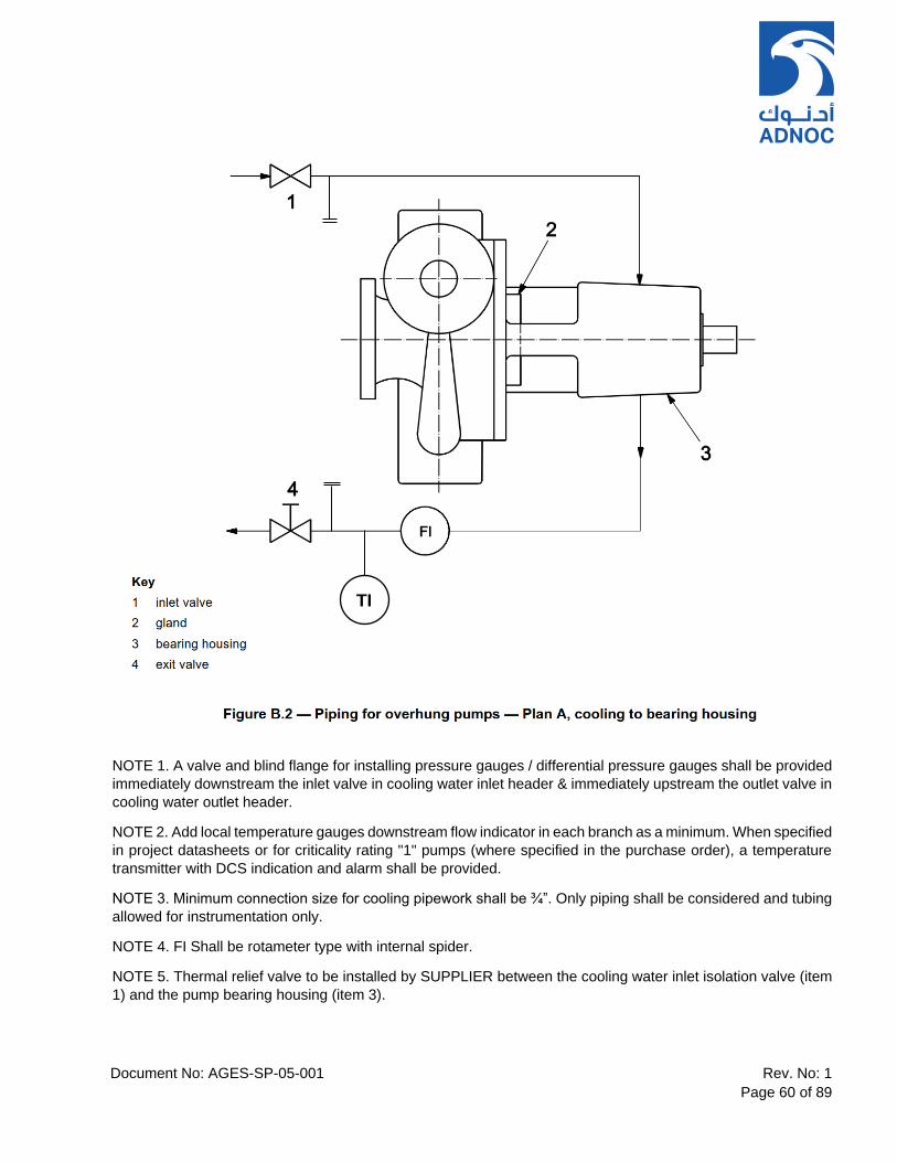
Document No: AGES-SP-05-001 Rev. No: 1
Page 60 of 89
NOTE 1. A valve and blind flange for installing pressure gauges / differential pressure gauges shall be provided
immediately downstream the inlet valve in cooling water inlet header & immediately upstream the outlet valve in
cooling water outlet header.
NOTE 2. Add local temperature gauges downstream flow indicator in each branch as a minimum. When specified
in project datasheets or for criticality rating "1" pumps (where specified in the purchase order), a temperature
transmitter with DCS indication and alarm shall be provided.
NOTE 3. Minimum connection size for cooling pipework shall be ¾”. Only piping shall be considered and tubing
allowed for instrumentation only.
NOTE 4. FI Shall be rotameter type with internal spider.
NOTE 5. Thermal relief valve to be installed by SUPPLIER between the cooling water inlet isolation valve (item
1) and the pump bearing housing (item 3).
TI

Document No: AGES-SP-05-001 Rev. No: 1
Page 61 of 89
NOTE 1. A valve and blind flange for installing pressure gauges / differential pressure gauges shall be provided
immediately downstream the inlet valve in cooling water inlet header & immediately upstream the outlet valve in
cooling water outlet header.
NOTE 2. Add local temperature gauges downstream flow indicator in each branch as a minimum. When specified
in project datasheets or for criticality rating "1" pumps (where specified in the purchase order), a temperature
transmitter with DCS indication and alarm shall be provided.
NOTE 3. Minimum connection size for cooling pipework shall be ¾”. Only piping shall be considered and tubing
allowed for instrumentation only.
NOTE 4. FI Shall be rotameter type with internal spider.
NOTE 5. Thermal relief valve to be installed by SUPPLIER between the cooling water inlet isolation valve (item
1) and the pump bearing housing (item 3).
TI
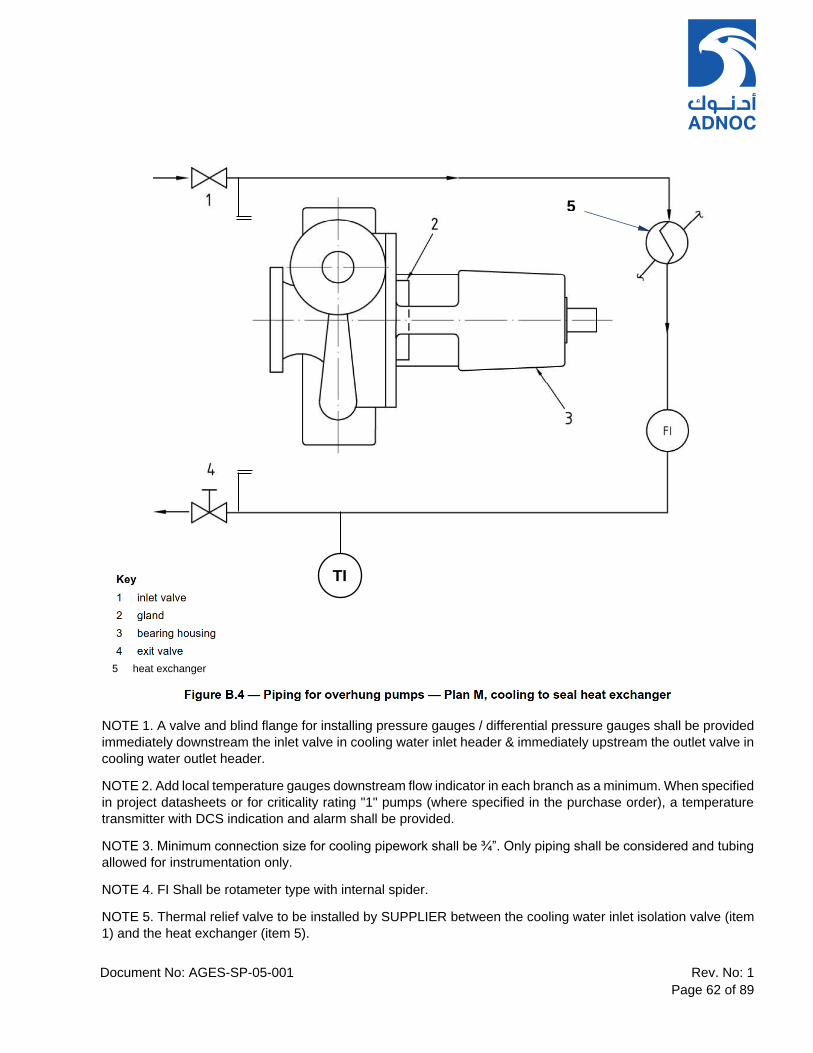
Document No: AGES-SP-05-001 Rev. No: 1
Page 62 of 89
NOTE 1. A valve and blind flange for installing pressure gauges / differential pressure gauges shall be provided
immediately downstream the inlet valve in cooling water inlet header & immediately upstream the outlet valve in
cooling water outlet header.
NOTE 2. Add local temperature gauges downstream flow indicator in each branch as a minimum. When specified
in project datasheets or for criticality rating "1" pumps (where specified in the purchase order), a temperature
transmitter with DCS indication and alarm shall be provided.
NOTE 3. Minimum connection size for cooling pipework shall be ¾”. Only piping shall be considered and tubing
allowed for instrumentation only.
NOTE 4. FI Shall be rotameter type with internal spider.
NOTE 5. Thermal relief valve to be installed by SUPPLIER between the cooling water inlet isolation valve (item
1) and the heat exchanger (item 5).
TI
5
5 heat exchanger
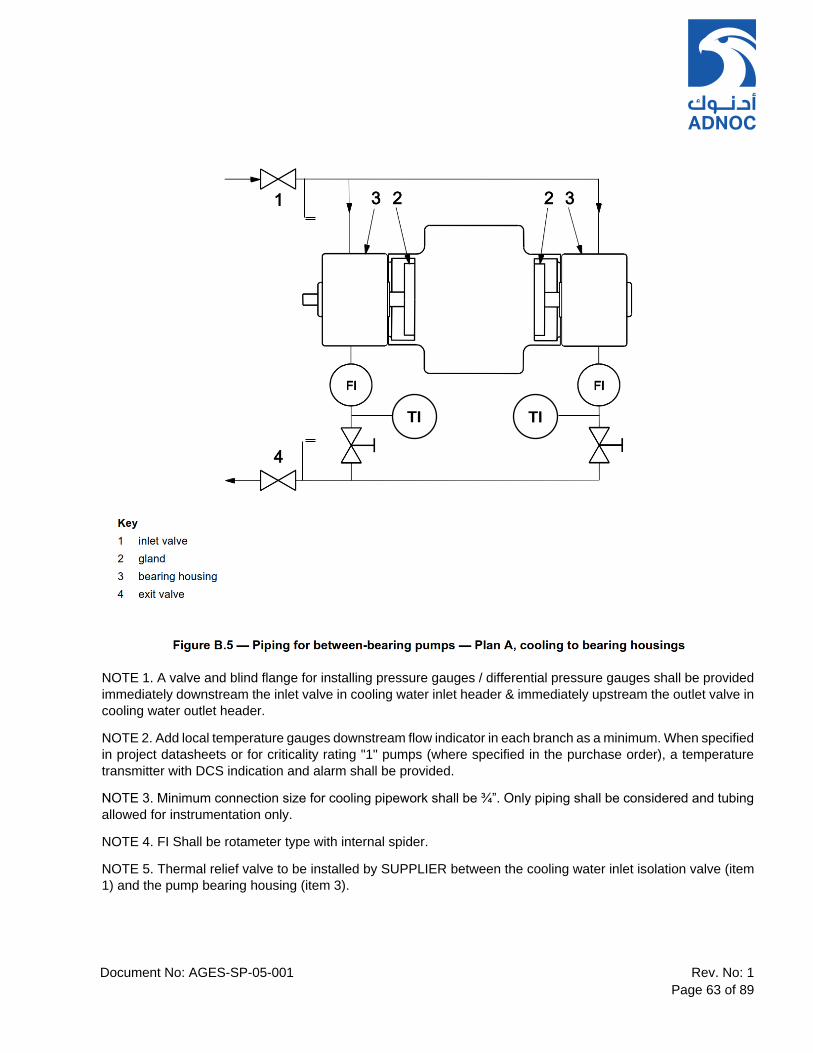
Document No: AGES-SP-05-001 Rev. No: 1
Page 63 of 89
NOTE 1. A valve and blind flange for installing pressure gauges / differential pressure gauges shall be provided
immediately downstream the inlet valve in cooling water inlet header & immediately upstream the outlet valve in
cooling water outlet header.
NOTE 2. Add local temperature gauges downstream flow indicator in each branch as a minimum. When specified
in project datasheets or for criticality rating "1" pumps (where specified in the purchase order), a temperature
transmitter with DCS indication and alarm shall be provided.
NOTE 3. Minimum connection size for cooling pipework shall be ¾”. Only piping shall be considered and tubing
allowed for instrumentation only.
NOTE 4. FI Shall be rotameter type with internal spider.
NOTE 5. Thermal relief valve to be installed by SUPPLIER between the cooling water inlet isolation valve (item
1) and the pump bearing housing (item 3).
TI TI

Document No: AGES-SP-05-001 Rev. No: 1
Page 64 of 89
NOTE 1. A valve and blind flange for installing pressure gauges / differential pressure gauges shall be provided
immediately downstream the inlet valve in cooling water inlet header & immediately upstream the outlet valve in
cooling water outlet header.
NOTE 2. Add local temperature gauges downstream flow indicator in each branch as a minimum. When specified
in project datasheets or for criticality rating "1" pumps (where specified in the purchase order), a temperature
transmitter with DCS indication and alarm shall be provided.
NOTE 3. Minimum connection size for cooling pipework shall be ¾”. Only piping shall be considered and tubing
allowed for instrumentation only.
NOTE 4. FI Shall be rotameter type with internal spider.
NOTE 5. Thermal relief valve to be installed by SUPPLIER between the cooling water inlet isolation valve (item
1) and the heat exchanger (item 5).
TI TI TI TI
5
5 heat exchanger

Document No: AGES-SP-05-001 Rev. No: 1
Page 65 of 89
NOTE 1. A valve and blind flange for installing pressure gauges / differential pressure gauges shall be provided
immediately downstream the inlet valve in cooling water inlet header & immediately upstream the outlet valve in
cooling water outlet header.
NOTE 2. Add local temperature gauges downstream flow indicator in each branch as a minimum. When specified
in project datasheets or for criticality rating "1" pumps (where specified in the purchase order), a temperature
transmitter with DCS indication and alarm shall be provided.
NOTE 3. Minimum connection size for cooling pipework shall be ¾”. Only piping shall be considered and tubing
allowed for instrumentation only.
NOTE 4. FI Shall be rotameter type with internal spider.
NOTE 5. Thermal relief valve to be installed by SUPPLIER between the cooling water inlet isolation valve (item
1) and the heat exchanger (item 5).
TI TI
5
5 heat exchanger

Document No: AGES-SP-05-001 Rev. No: 1
Page 66 of 89
Figure B.8 Class II-P0-R1-H0-BP0-C1F2-C0-PV1-TV1-BB0 or
Class II-P0-R1-H0-BP1-C1F2-C0-PV1-TV1-BB0
Unless otherwise specified, following requirements shall apply to the lube oil system shown in Figure B.8:-
NOTE 1. In the title, “BP0” indicates that the baseplate is part of the equipment, “BP1” indicates a stand-alone
console, reservoir-mounted. The P&IDs are similar.
NOTE 2. Figure modified from ISO 10438-2:2007, Figure B.1. For the purposes of this provision, API 614-08 is
the equivalent of ISO 10438-2:2007.
NOTE 3. Refer DGS 3335 001 for LO system requirements
NOTE 4. Oil reservoir shall be provided with Electric heater and Temperature transmitter for its operation.
NOTE 5. Sight glass to be provided in Lube oil return line to reservoir such as from PSV return, Control valve
return, each bearing return line etc.
NOTE 6. PT for each pump discharge before NRV. Only transmitters shall be used.
Document No: AGES-SP-05-001 Rev. No: 1
Page 67 of 89
NOTE 7. PDT to be provided across the filter.
NOTE 8. PALL to be provided on 2oo3 logic.
NOTE 9. Base plate to be integral with main.
NOTE 10. Water cooler shall be twin type whereas air cooler shall be single cooler with 2x100% fans/motors.
NOTE 11. Reservoir to be provided with spare connection (flanged and blinded) for oil purifier connection.
NOTE 12. TCV to be provided across the cooler.
NOTE 13. Temperature Indicator in each bearing return line (for pump, motor and gear box).
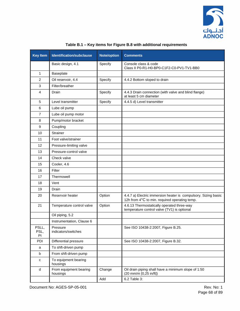
Document No: AGES-SP-05-001 Rev. No: 1
Page 68 of 89
Table B.1 – Key items for Figure B.8 with additional requirements
Key Item Identification/subclause Note/option Comments
Basic design, 4.1 Specify Console class & code Class II P0-R1-H0-BP0-C1F2-C0-PV1-TV1-BB0
1 Baseplate
2 Oil reservoir, 4.4 Specify 4.4.2 Bottom sloped to drain
3 Filter/breather
4 Drain Specify 4.4.3 Drain connection (with valve and blind flange) at least 5 cm diameter
5 Level transmitter Specify 4.4.5 d) Level transmitter
6 Lube oil pump
7 Lube oil pump motor
8 Pump/motor bracket
9 Coupling
10 Strainer
11 Foot valve/strainer
12 Pressure-limiting valve
13 Pressure-control valve
14 Check valve
15 Cooler, 4.6
16 Filter
17 Thermowell
18 Vent
19 Drain
20 Reservoir heater Option 4.4.7 a) Electric immersion heater is compulsory. Sizing basis:
12h from 4°C to min. required operating temp.
21 Temperature control valve Option 4.6.13 Thermostatically operated three-way temperature control valve (TV1) is optional
Oil piping, 5.2
Instrumentation, Clause 6
PSLL, PSL,
PI
Pressure indicators/switches
See ISO 10438-2:2007, Figure B.25.
PDI Differential pressure See ISO 10438-2:2007, Figure B.32.
a To shft-driven pump
b From shft-driven pump
c To equipment bearing housings
d From equipment bearing housings
Change Oil drain piping shall have a minimum slope of 1:50 (20 mm/m [0,25 in/ft])
Add 6.2 Table 3:
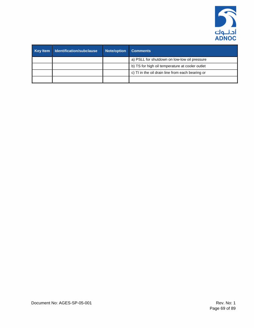
Document No: AGES-SP-05-001 Rev. No: 1
Page 69 of 89
Key Item Identification/subclause Note/option Comments
a) PSLL for shutdown on low-low oil pressure
b) TS for high oil temperature at cooler outlet
c) TI in the oil drain line from each bearing or

Document No: AGES-SP-05-001 Rev. No: 1
Page 70 of 89
11. ANNEX C – HYDRAULIC POWER RECOVERY TURBINES
ANNEX C
(normative)
HYDRAULIC POWER RECOVERY TURBINES
Table C.1 – Additional Design Requirements
C.1 General A HPRT shall be utilised as main pump driver where another standby pump is motor driven and used for initial start-up. For other applications, HPRT requires COMPANY approval. C.3.1 Fluid Characteristics C.3.1.1 [Add] This Clause shall apply and the CONTRACTOR shall indicate the properties of the fluid. C.3.1.2 [Replace in this Clause] “Purchaser” with “CONTRACTOR”. [Add] SUPPLIER to advise what changes, if any, to impellers are necessary to allow for gas evolution. SUPPLIER to confirm that gas evolution is uniform and that no slugging will occur in the HPRT. C.3.1.3 [Add] SUPPLIER to advise the minimum back pressure for safe operation of the HPRT. C.3.2 Seal Flushing System C.3.2 [Add] Mechanical Seals shall be supplied in accordance with API 682, as amended by respective COMPANY specifications... CONTRACTOR and SUPPLIER to agree the barrier fluid to ensure no contamination of the processed fluid occurs. C.3.3 Over speed Trip C.3.3.1 [Add] An electronic (2oo3) over speed trip shall be fitted for generator applications. C.3.3.2 [Add] When used as a pump drive, an over speed trip should not be necessary except as noted under C.3.3.3.
C.3.3.3 [Add] Rotors shall be designed for the maximum over speed expected from the train. Where over speed is expected to exceed 130% of normal speed an over speed trip shall be provided. Calculation of over speed Refer to Figure 2.
Where:- H1 = Head at zero power of HPRT and design speed H2 = TDH available from the process usually the HPRT design point N1 = Design speed N2 = Over speed The following typical arrangements are acceptable: HPRT – Coupling – Clutch – Pump – Coupling – Motor OR HPRT – Coupling – Clutch – Motor – Coupling – Pump Where pump speed gets reduced due to lower speeds of HPRT, a speed increasing gearbox may be added.
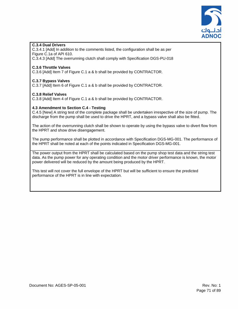
Document No: AGES-SP-05-001 Rev. No: 1
Page 71 of 89
C.3.4 Dual Drivers C.3.4.1 [Add] In addition to the comments listed, the configuration shall be as per Figure C.1a of API 610. C.3.4.3 [Add] The overrunning clutch shall comply with Specification DGS-PU-018 C.3.6 Throttle Valves C.3.6 [Add] Item 7 of Figure C.1 a & b shall be provided by CONTRACTOR. C.3.7 Bypass Valves C.3.7 [Add] Item 6 of Figure C.1 a & b shall be provided by CONTRACTOR. C.3.8 Relief Valves C.3.8 [Add] Item 4 of Figure C.1 a & b shall be provided by CONTRACTOR. 4.3 Amendment to Section C.4 - Testing C.4.5 [New] A string test of the complete package shall be undertaken irrespective of the size of pump. The discharge from the pump shall be used to drive the HPRT, and a bypass valve shall also be fitted. The action of the overrunning clutch shall be shown to operate by using the bypass valve to divert flow from the HPRT and show drive disengagement. The pump performance shall be plotted in accordance with Specification DGS-MG-001. The performance of the HPRT shall be noted at each of the points indicated in Specification DGS-MG-001.
The power output from the HPRT shall be calculated based on the pump shop test data and the string test data. As the pump power for any operating condition and the motor driver performance is known, the motor power delivered will be reduced by the amount being produced by the HPRT. This test will not cover the full envelope of the HPRT but will be sufficient to ensure the predicted performance of the HPRT is in line with expectation.
Document No: AGES-SP-05-001 Rev. No: 1
Page 72 of 89
12. ANNEX G – MATERIALS CLASS SELECTION GUIDANCE
ANNEX G
(Informative)
Materials Class Selection Guidance
Amendment to API 610 11th Edition, 2010
This Annex contains supplements to API 610 11th Edition and is intended to supplement the existing API 610
Annex G and Annex H and to provide general guidance on pump material selection. It should not be used without
a knowledgeable review of the specific services involved. Alternative material class selections may be used if
specified or if agreed upon by the COMPANY and the SUPPLIER.
This Annex provides a selection of the appropriate construction materials for centrifugal pumps in various
services. The pump SUPPLIER may offer, for COMPANY’s approval, alternative materials if, based on his
experience, these would render equal or better service. Such alternate materials shall be clearly indicated in the
SUPPLIER’S proposal as deviating from this specification.
Table G.1 – Supplements to API 610 Table G.1
This document identifies the recommended Pump and Gasket Material Groups for various types of fluids be
pumped. This table is to be used for guidance only and all determinations of Pump and Gasket Material Groups
shall be done on an individual basis by CONTRACTOR’S materials/corrosion specialists. The Material Groups
shall be shown on the Materials Selection Diagrams.
Table G.2 – Pump Material Group Specification
This document identifies, for each Pump Material Group, the required material specification for the various pump
parts. For pump parts designated as ASTM materials in Table 2, all the requirements of the applicable ASTM
specification shall be met, along with any other requirements included in Table 2. If non-metallic materials are
used, SUPPLIER shall propose suitable material for COMPANY approval.
Table G.3 – Gasket Selection relative to Gasket Material Group Specification
This document identifies, for each Gasket Material Group, the required gasket material.

Document No: AGES-SP-05-001 Rev. No: 1
Page 73 of 89
NOTES
1. For the services other than those covered in Tables of this Annexure, Table G-1 & Table H-1 of API 610,
11th Edition shall be referred.
2. For non-metallic wear part materials, Table H-3 of API 610, 11th Edition shall be referred
3. For Auxiliary piping materials, Table H-4 of API 610, 11th Edition shall be referred.
4. The following notes shall be added under API 610 11th Edition, Table H.4 – ‘Piping materials’.
c. Piping material specifications shall be in accordance with ASME B31.3 for process piping or ASME
B31.1 for power piping. All valves, filters and strainers shall have flanged connections in accordance
with ASME B16.5. Pipework flanges shall be RFWN type in accordance with ASME B16.5. All cooling
water piping, seal piping, pump drain and vent pipework shall be stainless steel AISI 316L material,
unless otherwise stated in the equipment datasheets.
d. The selection of instrument tubing materials shall be in accordance with ‘General Technical and
Contractual Requirements for Rotating Equipment’ (Ref. 2), unless otherwise specified in the
equipment datasheets.
e. All piping welds shall be butt welds (BW). Socket welds shall not be used. All pipework butt welds
(BW) shall be carried out in accordance with ASME IX. Butt welded pipe fittings shall conform to ASME
B16.9 and MSS SP43. Reference shall also be made to ‘Appendix 2 – QA Inspection and Testing
Requirements’.

Document No: AGES-SP-05-001 Rev. No: 1
Page 74 of 89
Table G.1 – Supplements to API 610 Table G.1: ADNOC Gas Processing, Refining and Borouge
Business Units
Service Temp Range °C
Materials Class
(Refer to Table G.2 below)
API 610 Table H.1
Material Class
Gasket Material Group
(Refer to Table G.3 below)
Notes
Short residue containing naphthenic acids (acid number above 0.5 mg KOH/g)
> 300 9,12 C-6, A-8 G7, G8, G11 6,7,9,16,17
Oil products containing sulphur compounds
> 260 9,12 C-6, A-8 G7, G8, G11 6,7,9,13,16
Oil products containing a corrosive aqueous phase
12 A-8 G11 13,18
Sour Hydrocarbon 2,12 S-5, A-8 8
Fresh water, aerated 9 C-6 G11 14
Fresh cooling water, air-free closed circuit or inhibited open circuit
2 S-5 G11 14
Condensate, non-aerated 2 S-5 G11 5,14
Condensate, aerated 9,12 C-6, A-8 G11 9
Brackish water ≤30 12,13 A-8, D-2 G12 15
>30 <75 15 N/A G12 10,15
Drain water, slightly acidic, non-aerated
12 A-8 G11
Toxic or lethal liquids, non-corrosive
0 to 45 7 N/A G11
Sulfolane (Shell proprietary chemical solvent)
S-5
G8, G11
Liquid chlorine, dry (max. 150 mg/kg water)
≤65 5 N/A G1
Hydrochloric acid, with or without hydrocarbons, or chlorinated hydrocarbons with or without free chlorine
≤100 25, 27, 28 N/A G2, G3 12,19
Hydrochloric acid, with or without hydrocarbons, in the absence of chlorinated hydrocarbons and/or free chlorine
≤100 24, 26 N/A G2, G3 12,19
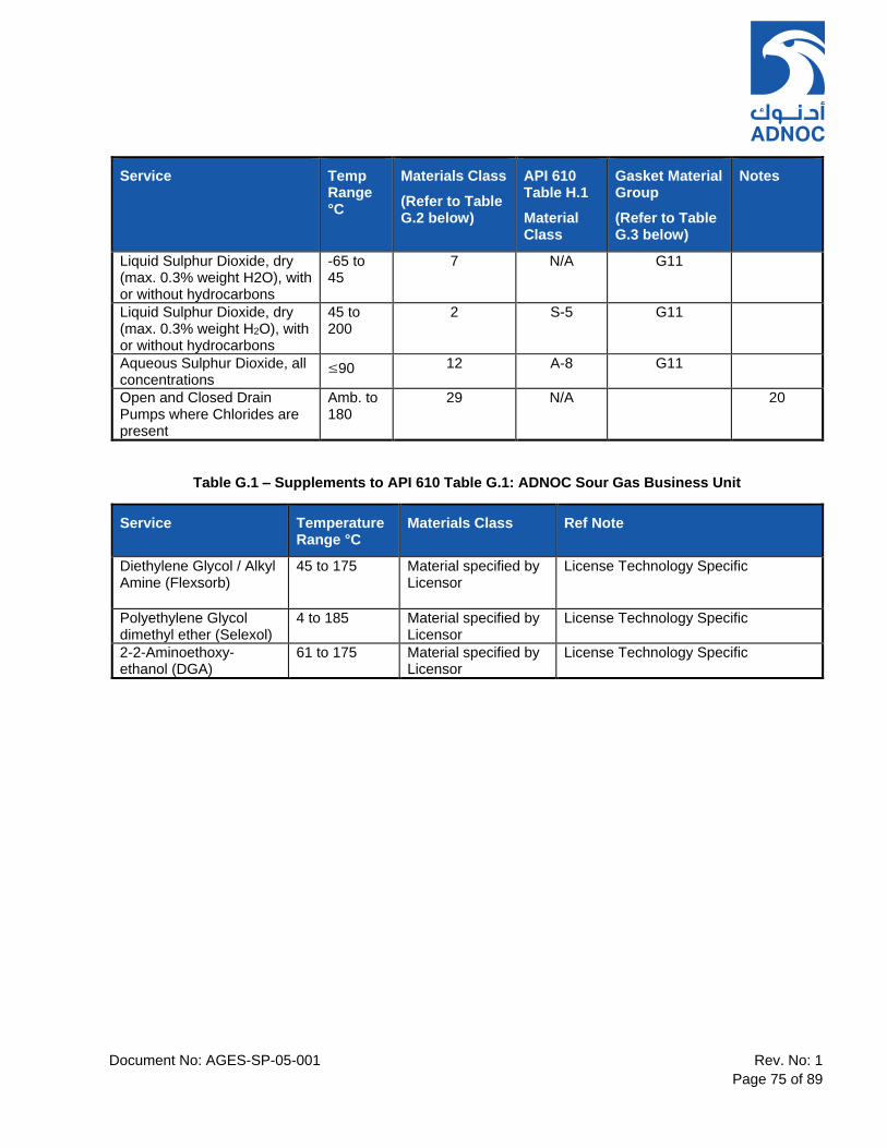
Document No: AGES-SP-05-001 Rev. No: 1
Page 75 of 89
Service Temp Range °C
Materials Class
(Refer to Table G.2 below)
API 610 Table H.1
Material Class
Gasket Material Group
(Refer to Table G.3 below)
Notes
Liquid Sulphur Dioxide, dry (max. 0.3% weight H2O), with or without hydrocarbons
-65 to 45
7 N/A G11
Liquid Sulphur Dioxide, dry (max. 0.3% weight H2O), with or without hydrocarbons
45 to 200
2 S-5 G11
Aqueous Sulphur Dioxide, all concentrations
≤90 12 A-8 G11
Open and Closed Drain Pumps where Chlorides are present
Amb. to 180
29 N/A 20
Table G.1 – Supplements to API 610 Table G.1: ADNOC Sour Gas Business Unit
Service Temperature Range °C
Materials Class Ref Note
Diethylene Glycol / Alkyl Amine (Flexsorb)
45 to 175 Material specified by Licensor
License Technology Specific
Polyethylene Glycol dimethyl ether (Selexol)
4 to 185 Material specified by Licensor
License Technology Specific
2-2-Aminoethoxy-ethanol (DGA)
61 to 175 Material specified by Licensor
License Technology Specific
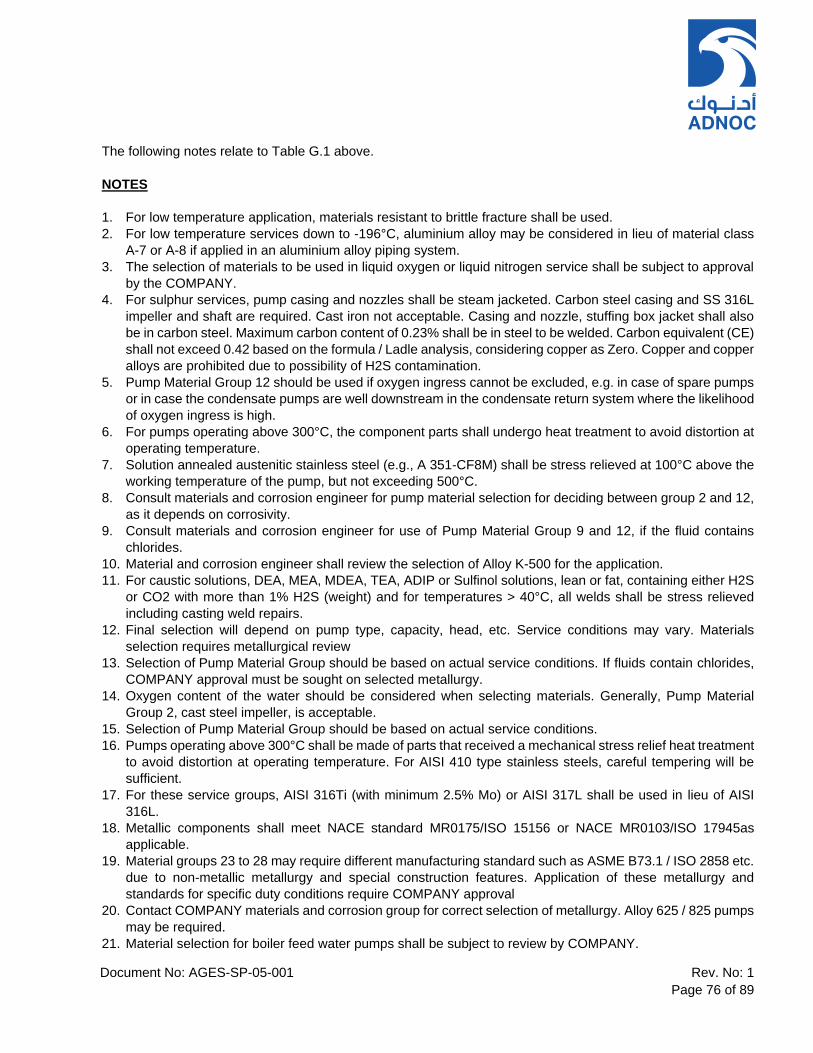
Document No: AGES-SP-05-001 Rev. No: 1
Page 76 of 89
The following notes relate to Table G.1 above.
NOTES
1. For low temperature application, materials resistant to brittle fracture shall be used.
2. For low temperature services down to -196°C, aluminium alloy may be considered in lieu of material class
A-7 or A-8 if applied in an aluminium alloy piping system.
3. The selection of materials to be used in liquid oxygen or liquid nitrogen service shall be subject to approval
by the COMPANY.
4. For sulphur services, pump casing and nozzles shall be steam jacketed. Carbon steel casing and SS 316L
impeller and shaft are required. Cast iron not acceptable. Casing and nozzle, stuffing box jacket shall also
be in carbon steel. Maximum carbon content of 0.23% shall be in steel to be welded. Carbon equivalent (CE)
shall not exceed 0.42 based on the formula / Ladle analysis, considering copper as Zero. Copper and copper
alloys are prohibited due to possibility of H2S contamination.
5. Pump Material Group 12 should be used if oxygen ingress cannot be excluded, e.g. in case of spare pumps
or in case the condensate pumps are well downstream in the condensate return system where the likelihood
of oxygen ingress is high.
6. For pumps operating above 300°C, the component parts shall undergo heat treatment to avoid distortion at
operating temperature.
7. Solution annealed austenitic stainless steel (e.g., A 351-CF8M) shall be stress relieved at 100°C above the
working temperature of the pump, but not exceeding 500°C.
8. Consult materials and corrosion engineer for pump material selection for deciding between group 2 and 12,
as it depends on corrosivity.
9. Consult materials and corrosion engineer for use of Pump Material Group 9 and 12, if the fluid contains
chlorides.
10. Material and corrosion engineer shall review the selection of Alloy K-500 for the application.
11. For caustic solutions, DEA, MEA, MDEA, TEA, ADIP or Sulfinol solutions, lean or fat, containing either H2S
or CO2 with more than 1% H2S (weight) and for temperatures > 40°C, all welds shall be stress relieved
including casting weld repairs.
12. Final selection will depend on pump type, capacity, head, etc. Service conditions may vary. Materials
selection requires metallurgical review
13. Selection of Pump Material Group should be based on actual service conditions. If fluids contain chlorides,
COMPANY approval must be sought on selected metallurgy.
14. Oxygen content of the water should be considered when selecting materials. Generally, Pump Material
Group 2, cast steel impeller, is acceptable.
15. Selection of Pump Material Group should be based on actual service conditions.
16. Pumps operating above 300°C shall be made of parts that received a mechanical stress relief heat treatment
to avoid distortion at operating temperature. For AISI 410 type stainless steels, careful tempering will be
sufficient.
17. For these service groups, AISI 316Ti (with minimum 2.5% Mo) or AISI 317L shall be used in lieu of AISI
316L.
18. Metallic components shall meet NACE standard MR0175/ISO 15156 or NACE MR0103/ISO 17945as
applicable.
19. Material groups 23 to 28 may require different manufacturing standard such as ASME B73.1 / ISO 2858 etc.
due to non-metallic metallurgy and special construction features. Application of these metallurgy and
standards for specific duty conditions require COMPANY approval
20. Contact COMPANY materials and corrosion group for correct selection of metallurgy. Alloy 625 / 825 pumps
may be required.
21. Material selection for boiler feed water pumps shall be subject to review by COMPANY.

Document No: AGES-SP-05-001 Rev. No: 1
Page 77 of 89
22. Applicable for all: All small internal parts and fasteners, such as screws, nuts, etc., which are not otherwise
specified, shall be made of material equal in corrosion resistance to the impellers. If the fluid being handled
is specified as non-corrosive, these parts may be of the manufacturer’s standard. Shaft keys at the impeller
may be similar material to the shaft material.

Document No: AGES-SP-05-001 Rev. No: 01
Page 78 of 89
Table G.2 – Centrifugal Pumps Material Group Specification
Pump Material Group
ISO 13709 Table H.1 Material Class
Casing Impeller Shaft Casing Wear Ring
Impeller Wear Ring
Inter-stage
Bushings
Inter-stage Sleeves
Wet Bolting Remarks
2 S-5 ISO 13709 Table H.2 (with Impeller(s) in A743 CA15/A182 F6NM and Shaft in Stainless Steel 4140/410)
5 Not
Applicable ASTM A352-
LCB ASTM
A743-CA15 Carbon Steel
AISI 420
(225-275
HBW)
AISI 420 (325-375
HBW)
AISI 420 (225-275
HBW)
AISI 420 (325-375
HBW) ASTM A193-B6
7 Not
Applicable
ASTM A352-LCB (Impact
tested)
ASTM A48 No. 40. (Max.
allowable tip speed is
55m/s)
ASTM A322 Gr. 4140
(quenched and
tempered)
AISI 420
(225-275
HBW)
AISI 420 (325-375
HBW)
AISI 420 (225-275
HBW)
AISI 420 (225-275
HBW) ASTM A320-L7
Consider a pump without a stuffing
box in case of service group 11.
9 C-6 ISO 13709 Table H.2 (with Casing in A217 CA15 / A743 CA15, Impeller(s) in A743 CA15 and Shaft in Stainless Steel 410)
12 A-8 ISO 13709 Table H.2 (with Casing in A351 CF3M, Impeller(s) in A744 CF3M and Shaft in Stainless Steel A276-316L)
13 D-2 ISO 13709 Table H.2 (with Casing in A890-5A, Impeller(s) in A890-5A and Shaft in SDSS UNS S32760)
15 Not
Applicable ASTM B148-
C95800
ASTM B148-
C95800
ASTM B150-C62300 or Alloy K-500 or Carbon
Steel (suitably
protected)
*ASTM B148-
C95800 or
ASTM B150-
C63200 or Alloy K-500
Alloy K-500 Min. 250
HBW
Alloy K-500 Max. 200 HBW
Alloy K-500 Min. 250
HBW
ASTM F467/468-C63000 or ASTM
F467/468-N05500
*All to be maximum 200
HBW
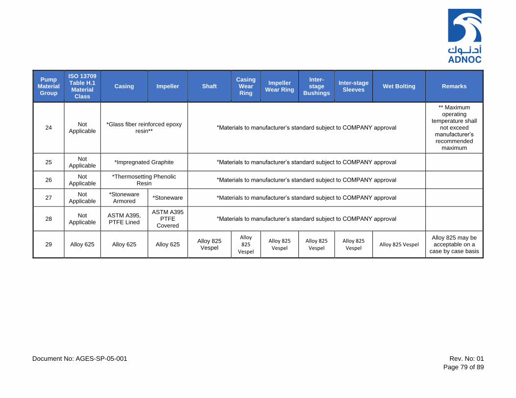
Document No: AGES-SP-05-001 Rev. No: 01
Page 79 of 89
Pump Material Group
ISO 13709 Table H.1 Material Class
Casing Impeller Shaft Casing Wear Ring
Impeller Wear Ring
Inter-stage
Bushings
Inter-stage Sleeves
Wet Bolting Remarks
24 Not
Applicable *Glass fiber reinforced epoxy
resin** *Materials to manufacturer’s standard subject to COMPANY approval
** Maximum operating
temperature shall not exceed
manufacturer’s recommended
maximum
25 Not
Applicable *Impregnated Graphite *Materials to manufacturer’s standard subject to COMPANY approval
26 Not
Applicable *Thermosetting Phenolic
Resin *Materials to manufacturer’s standard subject to COMPANY approval
27 Not
Applicable *Stoneware
Armored *Stoneware *Materials to manufacturer’s standard subject to COMPANY approval
28 Not
Applicable ASTM A395, PTFE Lined
ASTM A395 PTFE
Covered *Materials to manufacturer’s standard subject to COMPANY approval
29 Alloy 625 Alloy 625 Alloy 625 Alloy 825 Vespel
Alloy 825
Vespel
Alloy 825 Vespel
Alloy 825 Vespel
Alloy 825 Vespel
Alloy 825 Vespel Alloy 825 may be acceptable on a
case by case basis

Document No: AGES-SP-05-001 Rev. No: 01
Page 80 of 89
Table G.3: Gasket Selection Relative to Gasket Material Group Specification
GASKET
MATERIAL GROUP
MATERIAL
*MAX.
PRESS (bar g)
*MAX
TEMP
(C)
REMARKS
G1 Non-Asbestos 21 240 Note 3.
G2 PTFE compound
enveloped, Non-
Asbestos
**21 **220 Flat-faced. For Pump Material Group 28, it is
acceptable for the PTFE lining to serve as a
gasket. Notes 2 and 3.
G3
PTFE compound **21 **220 Flat-faced. For Pump Material Group 28, it is
acceptable for the PTFE lining to serve as a
gasket. Note 2.
G4 Nitrile Rubber **21 **220 Note 2.
G5 Viton (FKM) **21 220 Notes 2 and 5.
G6 Solid Monel 105 800
G7 Solid AISI 304 105 600
G8 Solid AISI 316 105 600
*G10 Solid Soft Iron 105 600 Note 1.
*G11 AISI 316 - Non-
Asbestos
105 675 Spiral wound. Notes 1 and 3.
*G12 Monel - PTFE 105 200 Spiral Wound. Notes 1 and 4.
Notes
1.* For higher pressure, special gaskets are required.
2.** Dependent on combination of fluid, pressure and temperature.
3.Non-Asbestos = Compressed, Non-Asbestos type
4.PTFE = Polytetrafluorethylene
5.Viton = Vinylidene – hexafluoropropylene (FKM)
Document No: AGES-SP-05-001 Rev. No: 01
Page 81 of 89
13. ANNEX H – MATERIALS AND MATERIAL SPECIFICATIONS FOR PUMP PARTS
Refer to Section 12, ANNEX G for details of supplements to API 610 11th Edition, Annex H.
Document No: AGES-SP-05-001 Rev. No: 01
Page 82 of 89
14. ANNEX P – REQUIREMENTS FOR DUPLEX OR SUPER DUPLEX STAINLESS STEEL CASTINGS
The supply and use of Duplex or Super Duplex Stainless Steel materials shall be in accordance with ISO
17782, ‘Petroleum, petrochemical and natural gas industries – Scheme for conformity assessment of
manufacturers of special materials’. The following specific requirements shall also apply.
a. Pump manufacturer shall prepare material specification for each duplex/super duplex stainless steel
casting order.
b. The casting manufacturer (or foundry) shall have adequate experience with casting the duplex/super
duplex stainless steel material with a minimum of 7 years’ experience.
c. The casting manufacturer (or foundry) must hold ISO 17782 qualification.
d. Casting manufacturer shall have a minimum of 3 years association with the pump manufacturer and fully
qualified and on their approved SUPPLIER list.
e. Material specification shall require that the casting manufacture is performed in accordance with the ISO
17782 manufacturing summary and Qualification Test Record (QTR) held by the Manufacturer for the
thickness required. Foundry shall present their qualification records to COMPANY for review, before
placement of order on foundry.
f. Material specification shall include the QA and QC requirements and all inspection requirements.
g. Each casting shall require BSEN 10204, Type 3.2 certification.
h. A detailed specific ITP (Inspection and Test Plan) shall be provided by the Foundry or Manufacturer to
include all required intervention and inspection points.
i. Material specification shall require that the casting manufacturer shall run a thermal analysis and fluid
thermodynamics simulation to calculate the temperature velocity distribution and quality criteria during the
filling and solidification process of the casting. The main objective is to assess the soundness of the casing
in terms of defects, especially shrinkage porosity. Thermal analysis of the layout casting including the
gating and feeding system shall verify the presence of defects in the produced casting. Software such as
MAGMASOFT developed by MAGMA Gmbh with required modules shall be used. Alternative software
may be proposed to COMPANY.
j. ITP shall include all the steps including software modelling, pattern preparation, chemical composition
control, thermal controls, pouring of casting, heat treatment and inspection.
k. Note: When a component type or size (thickness) is outside the scope of the existing ISO 17782 approval
held by the Manufacturer a new MPQT shall be performed in order to generate a new QTR for approval
and it shall be qualified in accordance with all requirements of ISO 17782 including non-destructive testing
and mechanical/corrosion tests.
l. In addition to the requirements of the material specification covered in the relevant ASTM standard, the
following additional tests shall be carried out on the production test bars/protrusions:-
1. ASTM A 923: Detrimental intermetallic phases to be determined by metallography
2. ASTM G48 Ferric Chloride testing, Method A to ensure correct heat treatment and absence of
detrimental phases
3. ASTM E562: Ferrite austenite point count shall be carried out.
m. Ferrite content shall be:
1. 35 to 55% for materials,
2. 35 to 65% for weld deposits and HAZ.
Document No: AGES-SP-05-001 Rev. No: 01
Page 83 of 89
n. Ferrite measurement using a ferritescope shall be carried out on the finished casting.
o. Positive Material Identification (PMI) shall be carried out.

Document No: AGES-SP-05-001 Rev. No: 01
Page 84 of 89
15. SUPPLEMENTARY REQUIREMENTS
15.1 Specific requirements applicable to individual business streams are detailed in ‘Business Unit Specific Requirements’ (Ref. 5).
Document No: AGES-SP-05-001 Rev. No: 01
Page 85 of 89
SECTION C – ADDITIONAL REQUIREMENTS
16. SCOPE OF SUPPLY
Refer to the List of Materials (LOM) within the material requisition and/or purchase order.
17. QUALITY CONTROL AND ASSURANCE
Equipment shall only be purchased from SUPPLIERS and SUB-SUPPLIERS approved by ADNOC Category
Management. This approval indicates that the SUPPLIER has an approved Quality Management System and
a proven track record in supply of this equipment type.
The SUPPLIER shall submit a proposed list of SUB-SUPPLIERS for all major components to COMPANY for
approval prior to order placement.
18. MATERIAL CERTIFICATION
18.1 For details of materials selection and associated material certification, refer to ‘General Technical and Contractual Requirements For Rotating Equipment’ (Ref. 2) and ‘QA Inspection and Testing’ Requirements (Ref. 3).
19. INSPECTION & TESTING REQUIREMENTS
19.1 The requirements for Inspection and Testing shall be specified in the ‘QA Inspection and Testing Requirements’ (Ref. 3).
20. SUB-CONTRACTORS / SUB- SUPPLIERS
20.1 Refer to ‘QA Inspection and Testing Requirements’ (Ref. 3) for details regarding SUB-SUPPLIERS.
21. SPARE PARTS
21.1.1 The SUPPLIER shall submit details of recommended spare parts for complete package. Refer to the ‘Information Requirements’ (Ref. 4).
21.1.2 The SUPPLIER shall include in his scope of supply the required quantities of CAPITAL spares as listed in Table 13 below.
Table 13 – Required Capital Spares for Centrifugal Pumps
Description Quantity Required Notes
Spare Shaft with Impeller ONE Single Stage Pumps. Only for pumps
without installed standby
Spare Rotor Bundle ONE Multi-Stage BB type Pumps
Mechanical Seal Cartridge(s) ONE set per pump type For horizontal BB type pumps include
DE and NDE
Seal Packing TWO sets per pump type For BB type pumps include DE and
NDE
Drive Coupling(s) ONE set per pump type Include high speed and low speed
couplings as applicable
Bearings / Bearing Pads ONE set per pump type For BB type pumps include DE and
NDE

Document No: AGES-SP-05-001 Rev. No: 01
Page 86 of 89
Description Quantity Required Notes
Bearing Housing Oil
Reservoir Level Sight Pot ONE per pump type Constant Level Oiler
Seal System Accumulator ONE per accumulator type/size Pressurized seal systems
Lube Oil Pump ONE spare unit per pump type Only for single duty pumps with no
installed standby unit
Lube Oil Cooler ONE spare unit per pump type Only for single duty pumps with no
installed standby unit
Shaft Sleeves ONE set per machine
Wear Rings ONE set per pump type
Gaskets & O-Rings TWO sets per pump type Non-standard parts (e.g. pump top
cover or end cover gaskets / seals)
22. PAINTING, PRESERVATION & SHIPMENT
22.1 Refer to ‘General Technical and Contractual Requirements for Rotating Equipment’ (Ref. 2).
23. INSULATION
23.1 Refer to ‘General Technical and Contractual Requirements for Rotating Equipment’ (Ref. 2).
24. COMMISSIONING
24.1 Refer to ‘General Technical and Contractual Requirements for Rotating Equipment’ (Ref. 2).
25. TRAINING
25.1 Refer to ‘General Technical and Contractual Requirements for Rotating Equipment’ (Ref. 2).
26. DOCUMENTATION/MANUFACTURER DATA RECORDS
26.1 Refer to General Technical and ‘Contractual Requirements for Rotating Equipment’ (Ref. 2) and the ‘Information Requirements’ (Ref. 4).

Document No: AGES-SP-05-001 Rev. No: 01
Page 87 of 89
27. GUARANTEES & WARRANTY
The SUPPLIER shall guarantee in all respects the correct functioning and performance of the supplied
equipment in accordance with the Purchase Order and attachments including the equipment datasheets and
referenced specifications. The SUPPLIER shall also warrant the equipment against all defects and failures for
the period stipulated in the Purchase Order or for not less than 12 months following site installation and
commissioning; and that during this period the equipment will continue to operate as intended and to meet the
specified performance, within the allowable/agreed test tolerances, without any deterioration in performance.

Document No: AGES-SP-05-001 Rev. No: 01
Page 88 of 89
SECTION D – DATASHEETS AND DRAWINGS
28. DATASHEETS TEMPLATES
Refer to ANNEX N of ‘Centrifugal Pumps for Petroleum, Petrochemical and Natural Gas Industries’ API 610
11th Edition (Ref. 1).
29. STANDARD DRAWINGS
Refer to the COMPANY business unit Structural Design Criteria for the design of equipment supports for onshore and offshore installations.
Refer to the COMPANY business unit standard drawings for details of anchor bolts.
Document No: AGES-SP-05-001 Rev. No: 01
Page 89 of 89
SECTION E – APPENDICES
APPENDIX 1: GENERAL TECHNICAL AND CONTRACTUAL REQUIREMENTS FOR ROTATING EQUIPMENT
APPENDIX 2: QUALITY ASSURANCE INSPECTION AND TESTING REQUIREMENTS
APPENDIX 3: INFORMATION REQUIREMENTS
APPENDIX 4: BUSINESS UNIT SPECIFC REQUIREMENTS
APPENDIX 5: INSTRUMENTATION AND CONDITION MONITORING REQUIREMENTS
APPENDIX 6: LUBRICATION SYSTEM DESIGN REQUIREMENTS
GENERAL TECHNICAL AND
CONTRACTUAL
REQUIREMENTS FOR
ROTATING EQUIPMENT
Appendix 1 – AGES-SP-05-001 1.
1.1.1
1.1.2
THE CONTENTS OF THIS DOCUMENT ARE PROPRIETARY AND CONFIDENTIAL
Appendix 1: AGES-SP-05-001 Effective Date: 19 March 2020 Rev. No: 00 Page 2 of 38
TABLE OF CONTENTS
1. PURPOSE ......................................................................................................................................... 4
2. DEFINED TERMS AND ABBREVIATIONS ..................................................................................... 4
3. NORMATIVE REFERENCES ........................................................................................................... 9
4. CONTRACTUAL REQUIREMENTS ............................................................................................... 13
4.1 DOCUMENTS PRECEDENCE ................................................................................ 13
4.2 SPECIFICATION DEVIATION AND CONCESSION CONTROL ............................ 13
4.3 ALTERNATIVE DESIGNS ....................................................................................... 14
4.4 PROTOTYPE DESIGNS .......................................................................................... 14
4.5 STANDARDISATION ............................................................................................... 14
4.6 QUALITY CONTROL (QA/QC) AND CERTIFICATION .......................................... 15
4.7 INSPECTION & TESTING REQUIREMENTS ......................................................... 15
4.8 SUPPLIER RESPONSIBILITIES ............................................................................. 15
4.9 SUBCONTRACTORS/SUBSUPPLIERS ................................................................. 16
4.10 SPARE PARTS ........................................................................................................ 17
4.11 SPECIAL TOOLS ..................................................................................................... 17
4.12 PAINTING ................................................................................................................. 18
4.13 PRESERVATION & SHIPMENT .............................................................................. 18
4.14 DOCUMENTATION/MANUFACTURER DATA RECORDS .................................... 20
4.15 GUARANTEES & WARRANTY ............................................................................... 20
5. TECHNICAL DESIGN REQUIREMENTS ...................................................................................... 21
5.1 GENERAL ................................................................................................................ 21
5.2 RELIABILITY............................................................................................................ 22
5.3 LOCATION & SITE CONDITIONS .......................................................................... 22
5.4 NOISE CONTROL .................................................................................................... 22
5.5 CASINGS ................................................................................................................. 23
5.6 MAIN PROCESS CONNECTIONS .......................................................................... 23
5.7 AUXILIARY PIPEWORK & INSTRUMENT CONNECTIONS ................................. 24
5.8 EXTERNAL FORCES AND MOMENTS .................................................................. 24
Appendix 1: AGES-SP-05-001 Effective Date: 19 March 2020 Rev. No: 00 Page 3 of 38
5.9 ROTATING ELEMENTS .......................................................................................... 24
5.10 BEARINGS AND BEARING HOUSINGS ................................................................ 24
5.11 SHAFT SEALS ......................................................................................................... 25
5.12 VIBRATION AND BALANCING .............................................................................. 25
5.13 LUBE OIL SYSTEMS ............................................................................................... 25
5.14 MATERIALS ............................................................................................................. 26
5.15 THERMAL INSULATION ......................................................................................... 27
6. ACCESSORY REQUIREMENTS FOR ROTATING EQUIPMENT ................................................ 27
6.1 DRIVERS .................................................................................................................. 27
6.2 GEARS ..................................................................................................................... 28
6.3 COUPLINGS, GUARDS ........................................................................................... 28
6.4 BASEPLATES.......................................................................................................... 29
6.5 CONTROLS & INSTRUMENTATION ...................................................................... 29
6.4 WIRING/CABLING ................................................................................................... 30
6.5 CONDITION & PERFORMANCE MONITORING .................................................... 31
6.6 PIPING & APPURTENANCES ................................................................................ 31
7. BUSINESS UNIT SPECIFIC CROSS REFERENCE ...................................................................... 31
7.1 ADNOC GAS PROCESSING ................................................................................... 31
7.2 ADNOC LNG ............................................................................................................ 33
7.3 ADNOC OFFSHORE ............................................................................................... 34
7.4 ADNOC ONSHORE ................................................................................................. 36
7.5 ADNOC REFINING .................................................................................................. 37
7.6 BOROUGE ............................................................................................................... 38

Appendix 1: AGES-SP-05-001 Effective Date: 19 March 2020 Rev. No: 00 Page 4 of 38
1. PURPOSE
1.1 This Appendix provides the general technical and contractual requirements for rotating equipment and its auxiliaries, as detailed for the COMPANY (ADNOC Group). Unless otherwise stated, these requirements shall apply to all rotating equipment.
1.2 This Appendix should be read in conjunction with: the relevant COMPANY rotating equipment specification and associated appendices and the Equipment Datasheet for the equipment being supplied as listed in the Purchase Order.
2. DEFINED TERMS AND ABBREVIATIONS
Abbreviations means the abbreviations listed in Table 1 or other referred to documents herein.
Certified Test or Certified Inspection means an Inspection or test activity which the SUPPLER conducts and certifies without PURCHASER involvement.
Coating MANUFACTURER means the MANUFACTURER of paint coating system to be applied to the
equipment to prevent corrosion or surface deterioration to equipment component parts.
“COMPANY” means ADNOC Group.
“Concession Request” means any request for deviation from the COMPANY requirements, either by the CONTRACTOR or SUPPLIER, usually after receiving the Contract package or Purchase Order. Often, it refers to a request for authorization to use, repair, recondition, reclaim, or release materials, components or equipment already in progress or completely manufactured but which does not meet or comply with ADNOC requirements. A Concession Request is subject to COMPANY approval.
“Continuous Operation” means the intended uninterrupted period of operation. Refer to equipment specific specifications for the definition of the duration of uninterrupted period of operation. The CONTRACTOR and SUPPLIER are responsible for highlighting any equipment, auxiliary components or system requirements which shall result in the need to shut down the equipment within this time period.
“CONTRACTOR” means the party or parties who undertake(s) all, or part, of the design, engineering, procurement, construction, commissioning or management of the Project.
“Hazardous Service / Hazardous Fluid” means any service or fluid as defined within the Process document: Process Design Criteria
“Intermittent Operation” means any operation which includes intentional starts and stops, or any irregular / non-routine usage.
Major Weld Repair of a casting is defined as "major" if a repair weld has a depth of more than 50% of the wall thickness or has a length of more than 150 mm (6 in) in one or more directions, or if the total surface area of all repairs on the casting exceeds 10% of the total casting surface area. A weld repair necessitated by a leaking pressure test is also classed as "major".
“MANUFACTURER” means the Original Equipment Manufacturer (OEM) or MANUFACTURER of one or more of the component(s) which make up a sub-assembly or item of equipment assembled by the main SUPPLIER or his nominated SUB-SUPPLIER.
“SUB-CONTRACTOR” means any party engaged by the CONTRACTOR to undertake any assigned work on their behalf. COMPANY maintains the right to review all proposed Sub-CONTRACTORs; this right does not relieve the CONTRACTOR of their obligations under the Contract, nor does it create any contractual relationship between COMPANY and the SUB-CONTRACTOR.
Appendix 1: AGES-SP-05-001 Effective Date: 19 March 2020 Rev. No: 00 Page 5 of 38
“SUB-SUPPLIER” means the sub-contracted SUPPLIER of equipment sub-components software and/or support services relating to the equipment / package, or part thereof, to be provided by the SUPPLIER. COMPANY maintains the right to review all proposed SUB-SUPPLIERS, but this right does not relieve the SUPPLIER of their obligations under the Contract, nor does it create any contractual relationship between COMPANY and any individual SUB-SUPPLIER.
“SUPPLIER” means the party entering into a Contract with COMPANY to provide the materials, equipment, supporting technical documents and/or drawings, guarantees, warranties and/or agreed services in accordance with the requirements of the purchase order and relevant specification(s). The term SUPPLIER includes any legally appointed successors and/or nominated representatives of the SUPPLIER.
Symbols means the symbols which are defined within ‘Process Design Criteria’

Appendix 1: AGES-SP-05-001 Effective Date: 19 March 2020 Rev. No: 00 Page 6 of 38
Table 1 – List of Abbreviations
Abbreviation Definition
1oo2, 2oo3, 2oo4 1 out of 2 , 2 out of 3, 2 out of 4 etc
BPVC (ASME) Boiler Pressure Vessel Code
CFD Computational Fluid Dynamics
CR Concession Request
CRA Corrosion Resistant Alloy
DBSE Distance Between Shaft Ends
DE / NDE Drive End / Non-Drive End
EDG Emergency Diesel Generator
EOC End of Curve
EPC Engineering Procurement Construction
ESD Emergency Shutdown
FEA Finite Element Analysis
H2S Hydrogen Sulfide
HF Hydrofluoric Acid
HIC Hydrogen Induced Cracking
HRC Measure of Hardness per the Rockwell “C” scale
HSSE Health, Safety, Security, Environment
Hv Vickers Hardness
2.1.1 ICSS 2.1.2 Integrated Control & Safety System
2.1.3 IEEE 2.1.4 Institute of Electrical and Electronic Engineers
2.1.5 IPS 2.1.6 Instrumented Protective System
2.1.7 ISO 2.1.8 International Organisation for Standardization
ITP Inspection & Testing Plan
LO Lubricating Oil

Appendix 1: AGES-SP-05-001 Effective Date: 19 March 2020 Rev. No: 00 Page 7 of 38
Abbreviation Definition
MACWP Maximum Allowable Continuous Working Pressure
MCS Maximum Continuous Speed
MSDS Material Safety Datasheet
MT Magnetic Particle Examination
NCR Non-Conformance Report
NDE or NDT Non-Destructive Examination or Non-Destructive Testing
NGL Natural Gas Liquid
OEM Original Equipment Manufacturer
PAUT Phased Array Ultrasonic Testing
PDCV Pressure Differential Control Valve
PQR Procedure Qualification Records
[PS] Process Safety (Mandatory Requirement)
PSD Process Shutdown
PSV Pressure Safety Valve
PT Penetrant Examination
QA / QC Quality Assurance / Quality Control
RCC Reinforced Cement Concrete
REI Rotating Equipment Initiative
RT Radiographic Examination
RTJ Ring Type Joint
SAT Site Acceptance Test
SPIR Spare Parts and Interchangeability Record
SPL Sound Pressure Level (dBA)
SWL Safe Working Load
UT Ultrasonic Examination

Appendix 1: AGES-SP-05-001 Effective Date: 19 March 2020 Rev. No: 00 Page 8 of 38
Abbreviation Definition
VFD Variable Frequency Drive
VI Visual Inspection
WPS Welding Procedure Specifications
WPQ Welding Procedure Qualification
WPQR Welding Procedure Qualification Record
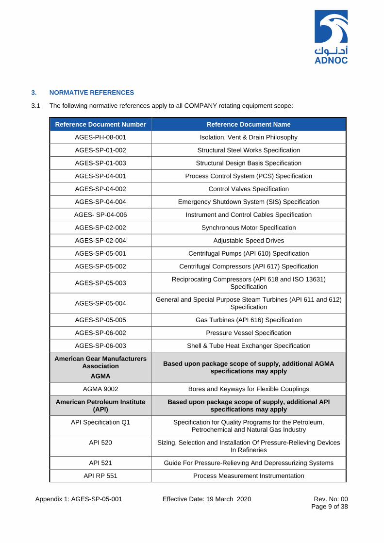
Appendix 1: AGES-SP-05-001 Effective Date: 19 March 2020 Rev. No: 00 Page 9 of 38
3. NORMATIVE REFERENCES
3.1 The following normative references apply to all COMPANY rotating equipment scope:
Reference Document Number Reference Document Name
AGES-PH-08-001 Isolation, Vent & Drain Philosophy
AGES-SP-01-002 Structural Steel Works Specification
AGES-SP-01-003 Structural Design Basis Specification
AGES-SP-04-001 Process Control System (PCS) Specification
AGES-SP-04-002 Control Valves Specification
AGES-SP-04-004 Emergency Shutdown System (SIS) Specification
AGES- SP-04-006 Instrument and Control Cables Specification
AGES-SP-02-002 Synchronous Motor Specification
AGES-SP-02-004 Adjustable Speed Drives
AGES-SP-05-001 Centrifugal Pumps (API 610) Specification
AGES-SP-05-002 Centrifugal Compressors (API 617) Specification
AGES-SP-05-003 Reciprocating Compressors (API 618 and ISO 13631)
Specification
AGES-SP-05-004 General and Special Purpose Steam Turbines (API 611 and 612)
Specification
AGES-SP-05-005 Gas Turbines (API 616) Specification
AGES-SP-06-002 Pressure Vessel Specification
AGES-SP-06-003 Shell & Tube Heat Exchanger Specification
American Gear Manufacturers Association
AGMA
Based upon package scope of supply, additional AGMA specifications may apply
AGMA 9002 Bores and Keyways for Flexible Couplings
American Petroleum Institute (API)
Based upon package scope of supply, additional API specifications may apply
API Specification Q1 Specification for Quality Programs for the Petroleum, Petrochemical and Natural Gas Industry
API 520 Sizing, Selection and Installation Of Pressure-Relieving Devices In Refineries
API 521 Guide For Pressure-Relieving And Depressurizing Systems
API RP 551 Process Measurement Instrumentation
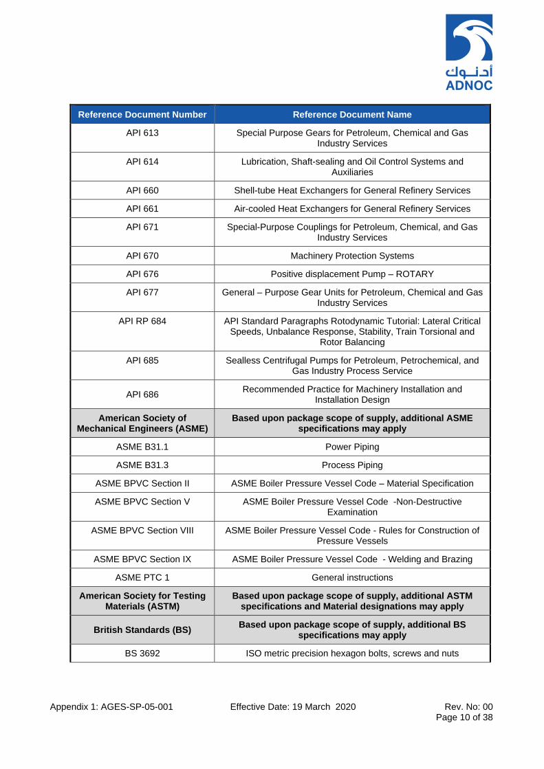
Appendix 1: AGES-SP-05-001 Effective Date: 19 March 2020 Rev. No: 00 Page 10 of 38
Reference Document Number Reference Document Name
API 613 Special Purpose Gears for Petroleum, Chemical and Gas Industry Services
API 614 Lubrication, Shaft-sealing and Oil Control Systems and Auxiliaries
API 660 Shell-tube Heat Exchangers for General Refinery Services
API 661 Air-cooled Heat Exchangers for General Refinery Services
API 671 Special-Purpose Couplings for Petroleum, Chemical, and Gas Industry Services
API 670 Machinery Protection Systems
API 676 Positive displacement Pump – ROTARY
API 677 General – Purpose Gear Units for Petroleum, Chemical and Gas Industry Services
API RP 684 API Standard Paragraphs Rotodynamic Tutorial: Lateral Critical Speeds, Unbalance Response, Stability, Train Torsional and
Rotor Balancing
API 685 Sealless Centrifugal Pumps for Petroleum, Petrochemical, and Gas Industry Process Service
API 686 Recommended Practice for Machinery Installation and
Installation Design
American Society of Mechanical Engineers (ASME)
Based upon package scope of supply, additional ASME specifications may apply
ASME B31.1 Power Piping
ASME B31.3 Process Piping
ASME BPVC Section II ASME Boiler Pressure Vessel Code – Material Specification
ASME BPVC Section V ASME Boiler Pressure Vessel Code -Non-Destructive Examination
ASME BPVC Section VIII ASME Boiler Pressure Vessel Code - Rules for Construction of Pressure Vessels
ASME BPVC Section IX ASME Boiler Pressure Vessel Code - Welding and Brazing
ASME PTC 1 General instructions
American Society for Testing Materials (ASTM)
Based upon package scope of supply, additional ASTM specifications and Material designations may apply
British Standards (BS) Based upon package scope of supply, additional BS
specifications may apply
BS 3692 ISO metric precision hexagon bolts, screws and nuts

Appendix 1: AGES-SP-05-001 Effective Date: 19 March 2020 Rev. No: 00 Page 11 of 38
Reference Document Number Reference Document Name
BS 4082: Part 1 Specification For External Dimensions For Vertical In-Line
Centrifugal Pumps
BS EN 1834 Reciprocating Internal Combustion Engines – Safety
requirements for the design and construction of engines for use in potentially explosive atmospheres
BS EN 10204 Metallic Products Types of Inspection Documents
BS EN 10241 Steel threaded pipe fittings
BSI PD 5304 Guidance on Safe Use of Machinery
Engineering Equipment & Materials Users Association (EEMUA)
EEMUA – 140 Noise Procedure Specification
EEMUA – 141 Guide to the use of Noise Procedure Specification
International Organisation for Standardization (ISO)
Based upon package scope of supply, additional ISO specifications may apply
ISO 2954 Mechanical Vibration of Rotating and Reciprocating Machinery - Requirements for Instruments for Measuring Vibration Severity
ISO 9000 Quality Management Systems - Fundamentals and Vocabulary
ISO 9004 Quality Management Guidelines for Performance Improvement
ISO 9563 Belt Drives - Electrical Conductivity of antistatic endless synchronous belts – Characteristics and Test Methods
ISO 9906 Rotodynamic pumps – Hydraulic performance acceptance tests, Grade 1, 2, 3.
ISO 10474 / EN 10204 Metallic products — Types of inspection documents
ISO 10816-1 Mechanical Vibration— Evaluation of Machine Vibration by Measurements on Non-rotating Parts
ISO 12944 Paints and varnishes - Corrosion protection of steel structures by protective paint systems
ISO 13050 Synchronous Belt Drives
ISO 15156 Materials for use in H2S-containing environments in oil and gas production
ISO 17782 Petroleum, petrochemical and natural gas industries – Scheme for conformity assessment of manufacturers of special materials
ISO 19011 Guidelines for Quality and/or Environmental System Auditing
ISO 21940 Mechanical Vibration – Rotor Balancing
ISO 21457 Material Selection & Corrosion Control for oil & gas
Manufacturers Standardization Society (MSS)
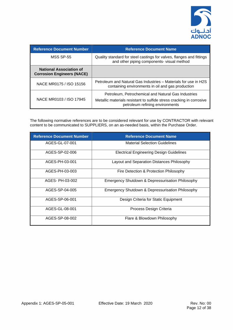
Appendix 1: AGES-SP-05-001 Effective Date: 19 March 2020 Rev. No: 00 Page 12 of 38
Reference Document Number Reference Document Name
MSS SP-55 Quality standard for steel castings for valves, flanges and fittings and other piping components- visual method
National Association of Corrosion Engineers (NACE)
NACE MR0175 / ISO 15156 Petroleum and Natural Gas Industries – Materials for use in H2S
containing environments in oil and gas production
NACE MR0103 / ISO 17945
Petroleum, Petrochemical and Natural Gas Industries
Metallic materials resistant to sulfide stress cracking in corrosive petroleum refining environments
The following normative references are to be considered relevant for use by CONTRACTOR with relevant content to be communicated to SUPPLIERS, on an as-needed basis, within the Purchase Order.
Reference Document Number Reference Document Name
AGES-GL-07-001 Material Selection Guidelines
AGES-SP-02-006 Electrical Engineering Design Guidelines
AGES-PH-03-001 Layout and Separation Distances Philosophy
AGES-PH-03-003 Fire Detection & Protection Philosophy
AGES- PH-03-002 Emergency Shutdown & Depressurisation Philosophy
AGES-SP-04-005 Emergency Shutdown & Depressurisation Philosophy
AGES-SP-06-001 Design Criteria for Static Equipment
AGES-GL-08-001 Process Design Criteria
AGES-SP-08-002 Flare & Blowdown Philosophy
Appendix 1: AGES-SP-05-001 Effective Date: 19 March 2020 Rev. No: 00 Page 13 of 38
4. CONTRACTUAL REQUIREMENTS
4.1 DOCUMENTS PRECEDENCE
4.1.1 In the event of any apparent conflict, the Order of Precedence for documents shall be as follows, in descending order of precedence:
(i) UAE Statutory Requirements and/or Regulations, including emissions limits
(ii) ADNOC Codes of Practice
(iii) Equipment Datasheet(s), Drawing(s) and Project Specifications
(iv) COMPANY Specifications
(v) Recognised Industry or International Codes and Standards
4.1.2 Where the requirements of the Equipment Datasheet or Specification are more stringent than UAE statute or regulation, the more stringent requirement shall apply, provided that this still achieves compliance with the law or regulation.
4.1.3 The SUPPLIER shall notify the COMPANY of any apparent conflict between the equipment specification and the equipment datasheet, or the equipment datasheet and local or statutory regulation. Resolution and/or clarification of the apparent conflict shall be obtained from the COMPANY, in writing, prior to proceeding with design or manufacture of the equipment.
4.2 SPECIFICATION DEVIATION AND CONCESSION CONTROL
4.2.1 Deviations
Deviations from the requirements of the Purchase Order are only acceptable where the SUPPLIER has
listed in their quotation the requirements they cannot, or do not wish to, comply with and the COMPANY
and CONTRACTOR have accepted, in writing, the deviations, before the order is placed.
In the absence of a list of agreed deviations, it will be assumed that the SUPPLIER complies fully
with the requirements of the Purchase Order.
4.2.2 Concessions
Any proposed, post award technical deviations to the Purchase Order and its attachments including, but
not limited to, the Datasheets and Narrative Specifications shall be sought by the SUPPLIER only through
the Concession Request procedure, as set out in Appendix 2 – Quality Requirements – of the relevant
equipment specification.
If, in the experience/knowledge of SUPPLIER and/or Sub-SUPPLIER, any requirements of the
specification create, or have a potential to create, unsafe (for personnel or plant) or less reliable function
during any operation (including start-up, upset or emergency operations), it is solely the SUPPLIER’s
responsibility to bring, in writing, such situations to the attention of the CONTRACTOR. If no situations
have been identified in writing, it will be construed that equipment and services will be provided as per the
specification.
Any proposed deviation or exception to the defined Process Safety requirements [PSR], as defined in Section 8 of the equipment specifications, shall require approval from ADNOC’s “Ultimate Technical Authority”.
Appendix 1: AGES-SP-05-001 Effective Date: 19 March 2020 Rev. No: 00 Page 14 of 38
4.3 ALTERNATIVE DESIGNS
4.3.1 The SUPPLIER may submit, in their proposal, alternative designs for consideration by CONTRACTOR / COMPANY, provided that this design satisfies all relevant statutory & legislative requirements, as well as all manufacturing, material and operating requirements as per the equipment specification and datasheet.
4.3.2 The SUPPLIER’s base proposal shall be as per the requirements of the enquiry package; this proposal may be supplemented by an additional proposal with alternative designs, clearly listing deviations to the enquiry. Proposals with only alternative designs are not acceptable. Alternative designs shall offer either improved reliability of the equipment or process scheme or reduced operational and/or maintenance cost to the COMPANY. Lifecycle cost for alternative designs shall be evaluated accurately by SUPPLIER and provided within their proposal. Reduced lead or delivery time alone shall not be reason to consider alternative designs. Alternative designs are subject to COMPANY approval.
4.3.3 The SUPPLIER shall supply a reference list for the offered equipment as part of their proposal.
4.4 PROTOTYPE DESIGNS
4.4.1 No new prototype, unproven equipment, nor equipment built to unknown manufacturing standards shall be offered. The equipment model incorporating "same as quoted" major components (as an example, impellers, casings, rotor configurations, bearings, shaft seals) shall have been proven in a similar environment (desert sand storms, dusty, hot, humid and salt laden atmosphere) and in similar operating conditions (flows, pressures, temperatures, powers, speeds) and service. The equipment model and its components shall be in the regular production range of the MANUFACTURER.
4.4.2 At least three machines similar in all major respects to those proposed shall have been manufactured and tested by the proposed MANUFACTURER at the proposed manufacturing plant, within the last 10 years and shall continue to be in trouble-free service. These three machines shall each have individually completed 3 years / 25,000 hours of satisfactory operation in a continuous process plant without any major problems or modifications.
4.4.3 The SUPPLIER shall list in their proposal all changes in parts, components or design which are not proven in similar machines produced for the last 10 years or which have not acquired at least 3 years / 25,000 hours in operation. These changes are specifically subject to the COMPANY’s approval and proven alternatives may be requested.
4.4.4 SUPPLIER/MANUFACTURER shall declare in their proposal to the COMPANY, their intention to use any unconventional methods to manufacture any item or component or "new" SUB-SUPPLIER whom they are nominating for the subject purpose for the first time. Use of unconventional methods and "new" SUB-SUPPLIERs is subject to COMPANY approval. For qualification of new SUPPLIERS, the SUPPLIER should have supplied at least 3 similar machines and have 3 years / 25,000hr continuous operation in similar operating conditions.
4.5 STANDARDISATION
4.5.1 SUPPLIER shall indicate in their proposal the names, manufacturing addresses and scope of supply of their SUB-SUPPLIERs. The SUB-SUPPLIER list requires COMPANY approval for each Purchase Order. No part of the order shall be sub-ordered without the prior written agreement of the COMPANY. COMPANY shall have the right to substitute a nominated SUB-SUPPLIER for any reason including rationalization, experience in similar service or technical superiority.
Appendix 1: AGES-SP-05-001 Effective Date: 19 March 2020 Rev. No: 00 Page 15 of 38
4.5.2 SUPPLIER shall standardize as much as possible across the project equipment, auxiliaries and
ancillaries. SUPPLIER shall provide all information within their proposal which they feel has the potential
to minimize the inventory of spare parts or the reduction of variety of equipment.
4.5.3 All ancillary items such as couplings, filters, seals, instruments etc. shall be in accordance with the
individual project’s approved SUPPLIER list.
4.6 QUALITY CONTROL (QA/QC) AND CERTIFICATION
4.6.1 The requirements for Quality Control and Quality Assurance shall be specified in the COMPANY
equipment specifications ‘Quality Assurance, Inspection and Testing Requirements’ Appendix 2.
4.6.2 The requirements for Material Identification and Certification shall be specified in the COMPANY
equipment specifications ‘Quality Assurance, Inspection and Testing Requirements’ Appendix 2.
4.6.3 All electrical and instruments, JBs, marshalling cabinets etc., control items shall be IECEx certified (based
on respective hazardous area classification requirements). The SUPPLIER is responsible for ensuring the
certification. This will enable the CONTRACTOR to obtain ECASEx certificates for those items in UAE by
payment of necessary verification fees. ATEX certification not acceptable unless approved by
COMPANY. Specific waivers are required in case where items cannot get IECEx certification.
4.7 INSPECTION & TESTING REQUIREMENTS
4.7.1 The requirements for Inspection and Testing Requirements shall be specified in the COMPANY equipment specifications ‘Quality Assurance, Inspection and Testing Requirements’ Appendix 2.
4.8 SUPPLIER RESPONSIBILITIES
4.8.1 SUPPLIER shall ensure that all equipment, and any free-issue equipment, is properly integrated into the whole installation in order to meet the applied specifications. Their responsibilities shall include, but not be limited to:
• Obtaining information required for fulfilling their obligations
• Ensure relevant integration of the equipment package into the overall plant design. This includes
review of the relevant PIDs, equipment layout, and where possible a basic review of other
equipment and instrumentation whose interface affects the performance of his equipment.
• Communicating necessary data, specifications and other documents with their Sub-
SUPPLIER(s).
• Negotiating physical interfaces, if any.
• Guaranteeing design, stability and performance of the complete equipment installation.
• Dimensional compatibility.
• Shaft system critical speeds and vibration, lateral and torsional analysis.
• Noise level limitations.
• Acceptability of externally imposed loads.
• Arrangement of auxiliary systems shall permit removal of main equipment for maintenance with
minimal removal of ancillaries
• Defining static and dynamic loads on foundations and support structures. Design verification of
support structures and foundations
• Standardizing all components within the train and its utility requirements (such as oil type/grade,
etc.)
• Integration of control systems.
• Advising CONTRACTOR of the firm requirement of utilities (type and quantity) within 2 months or
earlier as specified in the Purchase Order.
• Providing all software, software configuration/programming/troubleshooting devices for all
controllers such as speed, anti-surge, performance, load sharing, machine control, etc.

Appendix 1: AGES-SP-05-001 Effective Date: 19 March 2020 Rev. No: 00 Page 16 of 38
• Completion of "Maintenance Management System” datasheets for their and their Sub-
SUPPLIERs' equipment.
• Technical assistance to CONTRACTOR in defining control, shutdown and logic requirements to
be incorporated by CONTRACTOR in CONTRACTOR’s control and emergency shutdown (ESD)
system.
• Provide, or arrange to provide, all required assistance during installation, testing and
commissioning.
• Ensure that software and communication links shall match and compare with other
equipment/systems without any problems.
4.8.2 SUPPLIER shall independently compute, and thereby verify, the physical properties of the process medium as originally defined on the project datasheets and shall take full responsibility for amendment and resolution of any design features affected. SUPPLIER shall state in the equipment datasheets the values of all physical properties of process fluids used in their calculations, indicating the state equations used.
4.8.3 The SUPPLIER shall assist the CONTRACTOR during initial installation, alignment check and start-up. The initial start-up procedure shall be thoroughly documented by the SUPPLIER and supplied in the equipment’s installation manual, to be supplied prior to acceptance of the equipment. It shall be the SUPPLIER’s responsibility to advise the CONTRACTOR of training requirements needed for COMPANY personnel to safely and most efficiently operate and maintain their equipment.
4.8.4 The SUPPLIER and CONTRACTOR shall mutually agree responsibility for documenting and distributing “Minutes of the Meeting” for all meetings pertinent to the supplied equipment to which they are party. Typed copies of these minutes shall be submitted for mutual agreement, in the agreed format, within the specified duration but not longer than 3 days from the meeting. Following review, the originator of the minutes shall either correct and resubmit the minutes for agreement, or distribute the accepted minutes, within 2 working days.
4.8.5 The SUPPLIER shall provide spare parts as stipulated in COMPANY equipment specification and where listed in the Purchase Order.
4.8.6 The SUPPLIER shall provide special tools as stipulated in this Appendix and where listed in the Purchase Order.
4.9 SUBCONTRACTORS/SUBSUPPLIERS
4.9.1 The SUPPLIER/MANUFACTURER (as appropriate) shall assumer overall unit responsibility and guarantee for the equipment package and auxiliaries.
4.9.2 The SUPPLIER/MANUFACTURER shall transmit all relevant Purchase Order documents, including specifications and subsequent modifications to the specifications to their SUB-SUPPLIER(s).
4.9.3 The SUPPLIER/MANUFACTURER shall ensure all specified requirements are satisfied by their SUB-SUPPLIER(s).
4.9.4 The SUPPLIER/MANUFACTURER shall obtain and transmit all SUB-SUPPLIER(s) warranties to the CONTRACTOR and COMPANY in addition to the overall system / equipment warranty.
4.9.5 On the spare parts list, the SUPPLIER/MANUFACTURER shall include SUB-SUPPLIER‘s(s’) actual part number(s) for any sub-supplied parts, so that the COMPANY may directly source replacements from the SUB-SUPPLIER.
Appendix 1: AGES-SP-05-001 Effective Date: 19 March 2020 Rev. No: 00 Page 17 of 38
4.10 SPARE PARTS
4.10.1 Pre-Commissioning (i.e. Construction), Start-up (i.e. Commissioning) and Capital Spares, shall be provided in accordance with the requirements of COMPANY equipment specifications and as defined in the Purchase Order. Details of these shall be contained within the SUPPLIER’s proposal.
4.10.2 SUPPLIER shall provide the price for two years operational spares offer along with their proposal.
The following minimum requirements shall apply:
4.10.3 Spare parts shall be dimensionally and metallurgically identical to original parts, except that single stage centrifugal pump spare impellers shall be furnished with full diameter. Spare parts shall be subjected to the same level of quality control, inspection and testing as the job parts.
4.10.4 Spare parts shall be readily usable by replacing in the equipment, except that single stage centrifugal pump impellers may need trimming.
4.10.5 Instrument spares shall be readily usable by replacement in the equipment. If special jumpers or address switches need to be changed, those shall be ready-made for the specific application and shall be listed clearly on the spare part, packing documents with reference to the project number and machine contract number.
4.10.6 SUPPLIER shall specify whether or not any electronic chips need to be changed or reprogrammed. If there is a need, the chips (Eproms or others) shall be supplied ready programmed as a separate spare part with full reference to their electronic boards.
4.10.7 Spare parts shall be available for purchase and all manufacturing drawings retained throughout the specified 30 years’ service.
4.10.8 Spare parts shall be packaged, preserved and delivered in accordance with the requirements herein and any additional requirements prescribed in the Purchase Order. Furthermore, the SUPPLIER shall provide detailed storage, maintenance and preservation requirements for all supplied spares included specific long-term requirements for Capital Spares
4.10.9 Following award of Purchase Order all spares shall be listed by SUPPLIER under the SPIR submission and SUPPLIER shall indicate delivery, price and details of interchangeability for each part with the supplied equipment.
4.11 SPECIAL TOOLS
4.11.1 SUPPLIER shall provide all special tools required for installation, commissioning, disassembly and reassembly of the equipment. A list of the tools to be provided shall be included within the SUPPLIER’s proposal and shall include, but not be limited to, the following items as applicable to the equipment type:
a) Two sets of non-metric tools b) One set of bundle puller of each type, c) One bundle cradle and rotor stand for each bundle d) Tools for removal of gas turbine core engine, gas generator, power turbine & load coupling e) Mechanical seal removal tools f) Hydraulic clutch tools g) Bolt tensioning and torque devices h) Hydraulic tools for removing and assembling couplings hubs, thrust discs etc.(one set per service is
required) i) Software (including any third-party software) configuration devices for all controllers, I/O modules.
Software (including any third-party software) for reconfiguration of operator interface
Appendix 1: AGES-SP-05-001 Effective Date: 19 March 2020 Rev. No: 00 Page 18 of 38
j) Diagnostic software and hardware for all electronics k) CONTRACTOR as well as technician level diagnostic software for all machine condition / performance
monitoring, machine condition / performance evaluation l) Borescopes and light sources for all machinery designed to use such facilities m) Proof load tested spreader bars for all special purpose equipment and as required by CONTRACTOR n) Any special tools required to dismantle instrument items o) Special test clamps or leads for electronic / instrument checks, if any p) Brackets for installation of laser alignment tools (requirement to provide laser alignment tools shall be
on a project by project basis)
4.11.2 For two identical units, one set of special tools shall be provided.
4.11.3 For multi-unit installation of three or more identical units, two sets of special tools shall be provided.
4.11.4 Tools provided for use during operation shall be suitable for the specified area classification
4.12 PAINTING
4.12.1 Painting and protective coating(s) shall be applied in accordance with the specified requirements within the relevant COMPANY Business Unit Standard(s).
4.12.2 All exterior component parts, including stainless steel parts, but excluding finished machined surfaces, shall be painted in accordance with the project defined painting requirements as specified in Purchase Order. All protective coating system(s) used shall have a minimum service life of at least 7-8 years based on the specified site environmental conditions. The paint coating type, number of coats and thickness shall be as specified in COMPANY Standards.
4.12.3 Unless otherwise specified, atmospheric conditions in offshore and coastal environments (<50km from the coast) shall be considered to be corrosivity category C5-M, as per Part 2 of ISO 12944, whilst
onshore (≥50km from the coast) environments shall be considered as corrosivity category C3, as per ISO
12944.
4.13 PRESERVATION & SHIPMENT
4.13.1Preparation of equipment for transportation shall conform to the packing, marking, and shipping instructions identified in the Purchase Order. Preservation and shipment requirements will be stipulated in the equipment datasheet and project specification(s). However, as a minimum, the following requirements shall be applied:
The SUPPLIER shall ensure that all equipment is clean, sealed, protected and packed suitably for international shipment to ensure that all equipment will remain undamaged during transit and subsequent outdoor storage at the installation site for a minimum period of twelve (12) months or commissioning. The equipment packaging shall include adequate preservation to ensure that it will not require unpacking or disassembly, nor be subject to any deterioration during site outdoor storage prior to installation. Suitable protection shall be applied, which shall include, but not be limited to:
a) Covering flanged openings with metal cover plates and protecting exposed shaft ends against physical damage
b) Applying adequate bracing All temporary bracing/supports shall be marked “Remove before Equipment Commissioning and Start-up” and painted in red/white coloured stripes
c) Capping and securing open pipe/tube ends Female connections shall be plugged with solid metal pipe plugs, male connections shall be protected with full metal pipe caps
d) Boxing separately, all loose and spare parts.
Appendix 1: AGES-SP-05-001 Effective Date: 19 March 2020 Rev. No: 00 Page 19 of 38
e) Capital spare parts shall be suitable for 4 years storage in metallic containers, open to the sky. Pieces of equipment and spares shall be identified by item number and service and marked with CONTRACTOR’s order number, tag number and weight, both inside and outside of each contained. Spare parts shall also be tagged as “Spare”. A bill of materials shall be supplied within each package / container of parts
f) Covering exposed and machined surfaces, including bolting, with a coating of rust inhibiting compound. Spraying or coating internal metal surfaces with suitable rust preventative prior to shipment, which can be removed with liquid de-greaser. All openings shall be tagged to indicate the rust preventative applied
g) Mechanical seals, drive couplings, carbon rings, packed glands and other similar rotating seals shall be removed prior to shipment and packed separately, utilising suitable preservation and protection. Packing of mechanical seals and bearing assemblies shall be suitable to ensure these parts are fully protected from ingress of dust, sand, dirt, moisture or other foreign matter.
h) Seal chambers shall be protected from entry of foreign material.
i) Each item, crate, bag, etc., shall be identified in accordance with the marking requirements
specified in the Purchase Order.
j) Marking containers clearly to indicate whether they should be stored in the horizontal or vertical position
k) Marking containers clearly to demonstrate requirements for air conditioning l) Clearly highlighting any equipment requiring re-preservation and the incidence of re-preservation
in the packing list and on tags attached to the packaging. A procedure for re-preservation shall be supplied along with the delivery.
m) ADNOC Grade oils shall be specified
4.13.1 Equipment or materials that contain or are coated with any of the following shall be prominently tagged at openings to indicate the nature of contents and precautions for shipping, storage and handling:
o Insulating Oils o Corrosion Inhibitors o Antifreeze Solutions o Desiccants o Chemical Substances o Hydrocarbon Substances
4.13.2 Regulated substances shall have a Material Safety Datasheet (MSDS), which shall comply with regulations for MSDS preparation specified by the entity with jurisdiction and shall include a statement that the substance is considered hazardous by regulation. If a product is exempt from regulation, a statement to that effect shall be included. Before shipment, the MSDS shall be forwarded to the receiving facility and at shipment, MSDS in protective envelope shall be attached to the outside of the shipment.
4.13.3 Supplied vapour-phase inhibitor or silica gel crystals shall be easily accessible for removal. The bags shall be attached with stainless steel wire and their locations indicated with corrosion resistant tags fixed with stainless steel wire.
4.13.4 Long term storage instructions shall be prepared for all spare parts. Spare rotors for pumps, compressors and turbines shall be supplied in nitrogen pressurized metallic containers. Such containers shall be fitted with N2 blanketing provision, nitrogen cylinder, pressure indication, safety devices and audio-visual alarm to indicate loss of nitrogen pressure. Rotors shall be stored vertically to avoid sagging issues. However, the container shall have provision to allow support in both vertical and horizontal position.
4.13.5 Bearings and seals shall be removed prior to shipment and stored within separate long-term storage containers.

Appendix 1: AGES-SP-05-001 Effective Date: 19 March 2020 Rev. No: 00 Page 20 of 38
4.13.6 All Capital spares shall be packaged suitable for long term storage without having to reopen for condition monitoring.
4.13.7 SUPPLIER shall be responsible for the adequacy of preparation for shipment, to ensure that supplied equipment reaches the storage facility or plant (as appropriate) in the same condition as inspected and accepted prior to shipping.
4.13.8 The COMPANY shall reject any equipment received in a lesser condition to that accepted prior to shipping. Any costs associated with the return, repair or replacement of the equipment shall be the responsibility of the SUPPLIER.
4.13.9 Sea Transportation Loads (where applicable) shall be advised on a project by project basis.
4.13.10Maximum transportation envelope and weight limit shall be advised on a project by project basis.
4.13.11Packaging for offshore installations shall be applied as follows:-
a) Depending on overall layout, shelters for weather protection may be designed to enclose a number of units or individual units of machinery. For individual units, the shelter may be supplied by SUPPLIER and directly mounted on the machinery skid.
b) Installation and commissioning plans shall minimise the amount of time the equipment is installed offshore before start-up because of susceptibility to corrosion. If the time shall be excessive then long term preservation shall be initiated to protect the equipment.
4.14 DOCUMENTATION/MANUFACTURER DATA RECORDS
The SUPPLIER shall submit the required project documentation and Manufacturing Data Records as specified within the COMPANY ‘Information Requirements – Appendix 3 (Ref. 4) and the relevant equipment datasheet. The detailed format of documents shall be specified on a project basis in line with the relevant COMPANY Business Unit Standards.
4.15 GUARANTEES & WARRANTY
4.15.1Refer to relevant COMPANY equipment specifications and project datasheets for details of the required guarantees and warranties.

Appendix 1: AGES-SP-05-001 Effective Date: 19 March 2020 Rev. No: 00 Page 21 of 38
5. TECHNICAL DESIGN REQUIREMENTS
5.1 General
Operational Requirements
5.1.1 Equipment, including any auxiliaries, offered and supplied for Continuous Operation or Intermittent Operation shall be designed, manufactured, transported and installed to achieve a minimum service life of 30 years and at least 40,000 hours (5 years) of uninterrupted operation. Any equipment specific requirements relating to required years of uninterrupted operation, are defined in the relevant equipment specifications. If additional features are necessary to satisfy this requirement, the SUPPLIER shall list these in their offer. All replacement parts such as wear rings, throat bushes and seals shall have a minimum service life of 5 years to meet these criteria.
5.1.2 Equipment shall be sufficiently robust to withstand, without damage, the results of occasional abnormal conditions of limited duration.
5.1.3 Equipment specified for either continuous or intermittent service shall be capable of 3000 starts in 30 years unless otherwise specified on the equipment datasheet.
5.1.4 Equipment shall be suitable for the specified operation across the whole of the specified operating range, without the use of bypass, recirculation, venting or flaring.
5.1.5 Standby equipment- The requirements for standby equipment will be specified on the equipment datasheet.
5.1.5.1 All standby units shall be capable of quick, full-load start-up on demand – whether manual or automatic – without jeopardizing safety or plant operation. This requirement shall also apply to restarts from a shutdown, following resolution of the shutdown conditions.
5.1.5.2 Running and standby equipment shall be designed to start the stand-by before stopping the main equipment. System pressure, piping and process shall be designed to cater for both master and standby equipment running at the same time for a short period at changeover or test. Standby equipment shall have master/slave changeover facilities at field and remotely from the central control system.
Layout and Maintenance Requirements
5.1.6 All equipment shall be designed to permit rapid and economical maintenance, with all left-handed threads being clearly marked.
5.1.7 As far as practicable SUPPLIER and CONTRACTOR shall ensure the equipment layout, shall be arranged to avoid dismantling of suction and discharge pipework, steel support structures, or accessories (e.g. seal pots, exchangers, cable trays, junction boxes, etc.) during equipment maintenance and/or overhaul activities.
5.1.8 Couplings shall have unhindered access from both sides for their removal, alignment and for condition monitoring of machine bearings etc.
5.1.9 Equipment baseplates or skids shall be sized and designed, as much as possible, to provide safe and easy operation and maintenance access. Overly compact designs which do not permit safe access shall not be accepted. Minimum walk space within the skid for packaged equipment shall be at least 0.7 m. Baseplates / skids / flooring shall be fabricated with a non-slip surface and capable of withstanding loads associated with operation and maintenance.
Appendix 1: AGES-SP-05-001 Effective Date: 19 March 2020 Rev. No: 00 Page 22 of 38
5.1.10 Site equipment local manual trip mechanism(s) shall be safely and easily accessible with direct approaches without any hindrance or step overs. Where electric motor driven auxiliaries are provided as part of the equipment package local emergency stop stations shall be installed adjacent to each electric motor.
5.1.11 All major rotating equipment will have a dedicated facility for lifting by electrically operated cranes. All other rotating equipment shall have provision for safe and free access to appropriate lifting equipment (cranes, forklifts, etc.). EOT (electric overhead travelling) crane SWL shall be sized for 150% of maximum values, to allow for slings and other attachments. CONTRACTOR, with input from SUPPLIER, shall prepare a material handling study, which shall include detailed mechanical handling drawings, including capacity of crane, crane location, lifting methods, accessibility, paved areas etc.
5.1.12 Any maintenance item heavier than 15 kg shall be provided with lifting lugs or similar fixed lifting point(s). Screw-in eyebolts are only acceptable for internal components where other lifting arrangements are impractical. Lifting equipment will be provided for all items over 15 kg.
5.1.13 All medium/large filter housings and small knockout drums shall have self-supported covers over hand/manway access and/or filter element removal openings.
5.2 Reliability
5.2.1 Equipment and its auxiliaries shall be conceived, configured, designed, manufactured, transported, installed and commissioned to achieve the specified overall plant availability throughout the specified life of the installation. Equipment reliability shall be at least 99%.
5.2.2 The SUPPLIER shall provide an estimate of their equipment’s reliability, based upon their design, as part of their proposal.
5.3 Location & Site Conditions
5.3.1 Unless specified for offshore use, equipment will be located in a desert environment with high ambient air temperatures, sand and dust storms, highly humid salt laden atmosphere, near to coastal areas. Equipment specified for offshore use will be located in a marine, saliferous environment with high ambient air temperatures.
5.3.2 All equipment shall be tropicalized and capable of operating unattended and in the open, including in direct sunlight, unless otherwise specified.
5.3.3 The SUPPLIER shall provide specific written confirmation of compliance with the specification for outdoor sun-exposed equipment.
5.3.4 The SUPPLIER shall recommend in the proposal any additional provisions not specified by the COMPANY that are required to satisfy the operating conditions.
5.3.5 Roofing shall not be considered as an indoor environment.
5.3.6 Local gauge boards and instruments shall be fitted with sunshades.
5.4 Noise Control
5.4.1 The SUPPLIER shall submit guaranteed maximum sound pressure and sound power level data for the equipment at each octave band, together with any other relevant information as required. The sound pressure level (SPL) from the driven equipment, gearbox, driver and associated auxiliaries shall not exceed the value specified in the equipment datasheet or a maximum of 85dBA at 1 metre in all directions, whichever is less.

Appendix 1: AGES-SP-05-001 Effective Date: 19 March 2020 Rev. No: 00 Page 23 of 38
5.4.2 The SUPPLIER shall indicate any special noise attenuation measures required to meet the noise limits specified on the equipment datasheet. ISO 3740[7], ISO 3744[8] and ISO 3746[9] may be consulted for guidance.” Furthermore, the COMPANY Business Unit specific noise insulation material specifications shall apply.
5.4.3 If acoustic attenuation treatment is required to satisfy the specified noise limit, the SUPPLIER shall confirm full details of any measures proposed the predicted treated and untreated noise levels, together with associated cost impact(s). The supply of noise enclosures may also require the provision of associated fire extinguishing system(s) and additional fire and gas detection instrumentation, inside and/or outside the enclosure. This is subject to COMPANY approval.
5.5 Casings
5.5.1 Pressure retaining casings shall not be fabricated in any form of cast iron.
5.5.1 For large and/or high-speed turbo-machinery, provisions shall be made by the SUPPLIER for verification of hot alignment during operation using optical instruments. SUPPLIER shall ensure that there is sufficient space available for installing benchmark 5/16-inch (8.0 mm) dowel pins on each side of bearing housings and casings, as close to the shaft centerline as possible and that observation of the optical measurement scales is unobstructed. SUPPLIER’s representative shall participate in final alignment in the field Refer to Appendix 2 of equipment specifications for details of SAT requirements.
5.5.2 Internals of casings shall be positively locked in place, such that on failure or coming loose they cannot fall into and damage the equipment.
5.5.3 Connections on the upper half of the casing of axially split machinery are not acceptable without the approval of COMPANY.
5.5.4 Casing openings for pipe or auxiliary connections shall be not less than ¾” NPS and shall be flanged.
Threaded connections shall not be used. Where flanged openings are impractical on weldable casings, openings of 1” NPS or larger shall be full penetration butt weld connections, not socket weld connections.
5.6 Main Process Connections
5.6.1 When the main process connections are flanged, they shall be fully drilled. No threading in the flanges is allowed. As a minimum, where API standards are specified, all process connection flanges shall be ANSI Class 300# rating.
5.6.2 Flat-faced flanges shall not be accepted.
5.6.3 Where flanged openings are impractical due to space limitations or process conditions, such as Hazardous Service(s), openings of 1” NPS or larger shall be full penetration butt weld connections, not socket weld connections.
5.6.4 A pipe nipple, preferably not more than 150 mm (6 inches) long shall be used, minimum Schedule 80, and provided with a weld-neck flange. Connection to the outer pressure casing shall be by butt-welding.
5.6.5 Tapped openings on casings containing process streams that are not connected to piping shall be flanged or plugged, using solid round-headed steel plugs per ANSI B16.11, and seal-welded.
5.6.6 RTJ flanges shall be used for hydrogen and all sour service applications on flange ratings of PN 110 (ASME Class 600) and above
Appendix 1: AGES-SP-05-001 Effective Date: 19 March 2020 Rev. No: 00 Page 24 of 38
5.7 Auxiliary Pipework & Instrument Connections
5.7.1 All SUPPLIER auxiliary pipework interface connections including all drains, vents and utility supply/return lines shall be located at the edge of the baseplate(s) and shall include an isolation valve and blind flange. Unless approved otherwise, a single connection is required for each category of fluid service.
5.7.2 All instrument and control connections shall comply with instrument connection standards for their fittings and glands. They shall be located in a safe place away from rotating, hot and hazardous parts. They shall have easy and safe access for individual operation and maintenance purposes.
5.8 External Forces and Moments
5.8.1 Specific values for allowable forces and moments on main process nozzles shall be included in individual equipment specifications and the equipment datasheet and these will be used during bid evaluation.
5.8.2 For packaged equipment with SUPPLIER piping and with CONTRACTOR tie-in connections, SUPPLIER’s allowable loads and moments shall be followed. SUPPLIER shall anchor their pipework on skids close to battery limit connections. SUPPLIER shall carry out stress analysis within their skids and reports shall be submitted as part of their package documentation.
5.8.3 If SUPPLIER’s stress analysis indicates that loadings will exceed the allowable limits, the SUPPLIER shall consider rerouting, rearrangement and/or support of their equipment. The SUPPLIER shall notify the COMPANY prior to undertaking any modification. If these remedial measures do not sufficiently reduce the expected loadings, the SUPPLIER shall approach the CONTRACTOR and COMPANY to establish whether the additional loading can be absorbed into the tie-in connections, without causing loss of integrity or performance.
5.8.4 All equipment shall be capable of safely withstanding, without reduction in performance, all anticipated forces and moments acting across the whole of the operating range of equipment as defined on the datasheet.
5.9 Rotating Elements
5.9.1 SUPPLIER shall, jointly with driver MANUFACTURER (driven machine MANUFACTURER if generator application), establish the maximum transient torque that will occur in all rotating components under start up, running, and fault conditions. Detailed requirements shall be stipulated in the COMPANY equipment specifications. In the event that meeting this requirement requires an increase to the equipment frame size, the COMPANY shall be informed and confirm their acceptance prior to undertaking any amendments to the design.
5.10 Bearings and Bearing Housings
5.10.1 Cooling coils shall not be provided as means of bearing oil cooling.
5.10.2 Bearing housing shall be fitted with adequate bearing guards to minimize ingress of atmospheric dust and sand. Labyrinth seals alone are not considered adequate. On large machines, capability for air/nitrogen purge at bearing housing labyrinths shall be provided.
5.10.3 Unless anti-rotation devices are provided in accordance with 7.1.5 of this Appendix, sleeve or tilting-pad radial and thrust bearings shall be capable of withstanding reverse rotation for a short period of time without damage. The SUPPLIER shall advise in the proposal the estimated duration and maximum speed the bearing can withstand without damage in a reverse rotation mode.
5.10.4 Bearing rating shall be based on the highest oil temperature conditions resulting from continuous operation at the maximum ambient temperature specified. Hydrodynamic bearings shall be sized to limit babbitt temperature at the location of the temperature sensors. The maximum bearing metal temperatures under

Appendix 1: AGES-SP-05-001 Effective Date: 19 March 2020 Rev. No: 00 Page 25 of 38
any load conditions and at the maximum specified oil inlet temperature and worst specified ambient and cooling conditions, is defined in the relevant COMPANY rotating equipment specification.
5.10.5 Permanently sealed bearings shall not be acceptable for any equipment.
5.11 Shaft Seals
5.11.1 Seals shall be capable of removal on site without moving the driving or driven equipment, including gear boxes.
5.11.2 Unless anti-rotation devices are provided shaft seals shall be bi-directional. The SUPPLIER shall comment in the proposal the estimated duration and maximum speed the seals can withstand without damage in a reverse rotation mode.
5.12 Vibration and Balancing
5.12.1 The SUPPLIER shall demonstrate, by appropriate calculation, that the design does not suffer harmful resonance excited by any harmonic speed. If this is not available, a frequency test shall be performed to demonstrate that the equipment is free from harmful resonance.
5.12.2 Balancing procedures shall be such that rotor and coupling interchangeability can be achieved without the need for rebalancing. This will require rotors to be first balanced without couplings, and then to be check balanced with coupling hubs mounted.
5.12.3 Relative radial position of the coupling hubs with respect to shaft to be clearly marked to avoid assembly errors.
5.12.4 Standards for balance and vibration are specified in applicable COMPANY equipment specifications. For other rotating equipment types, the requirement within the applicable API standard shall take precedence.
5.12.5 Balance procedures shall be such that balance repeatability can be ensured. Balance procedures and results are subject to COMPANY approval.
5.12.6 Unless more stringent values are specified elsewhere, vibration amplitude at any non-synchronous speed at any operating condition shall not exceed 10% of the allowable vibration at synchronous speed.
5.12.7 Where non-contact vibration probe system are installed, the SUPPLIER shall indicate in their proposal the permissible alarm and trip values for the safe running of the machine.
5.13 Lube Oil Systems
5.13.1 Details of the lubrication system design requirements for specific equipment types are defined in the relevant COMPANY equipment specifications.
5.13.2 Grease lubricated bearings shall not be accepted unless otherwise indicated on the equipment datasheet, with the exception of electric motors, air cooler fans and pumps with power ratings up to 100kW, where grease lubricated bearings can be accepted subject to COMPANY approval.
5.13.3 All bearing lubrication systems shall be capable of operating in extreme site conditions without loss of bearing system reliability or integrity. Reliable and well proven bearing guards / isolators are required.
5.13.4 Oil mist lubrication shall not be used, with the exception of applications within the ADNOC Refinery Business Group where oil mist lubrication can be offered and can be used if approved by the COMPANY.

Appendix 1: AGES-SP-05-001 Effective Date: 19 March 2020 Rev. No: 00 Page 26 of 38
5.13.5 Grades of lubricating and sealing oils/grease shall be minimized and compatible with existing COMPANY plants / equipment. Utilisation of ADNOC Grade lubricating oil and grease is mandatory unless the specific grade is not manufactured by ADNOC. Lubricant type shall be stamped or etched on the equipment nameplate.
5.13.6 If the driver and driven equipment both require pressure lubrication, then a common pressure lubrication system shall be provided.
5.13.7 Lube oil coolers shall be designed in accordance with the relevant COMPANY static equipment specifications and referenced standards.
5.14 Materials
5.14.1 SUPPLIER may offer alternative materials to those specified in the requisition if, based on his experience, these would be better suited for the application. The use of any alternative materials is subject to the written approval of COMPANY metallurgist. Following placement of a Purchase Order by COMPANY, any proposed deviations to the specified requirements must be submitted to CONTRACTOR/COMPANY by means of a formal Concession Request identifying full technical details of the proposed deviation together with the associated cost and schedule impact.
5.14.2 All pressure retaining castings shall have the material designation embossed or engraved on each part.
5.14.3 SUPPLIER shall select materials suitable for the process fluid composition(s) given in the data/requisition sheets for all cases.
5.14.4 For equipment handling fluids containing aqueous hydrogen sulfide in concentrations of 50 ppm H2S or greater, all components including associated systems and ancillaries in contact with the fluid as well as the external bolting on the casing and seal glands shall conform to the requirements of MR0175/ISO 15156 or NACE MR0103/ISO 17945 as applicable. Ferrous materials not covered by MR0175/ISO 15156 or NACE MR0103/ISO 17945 shall have a maximum hardness of 248 Hv10. This hardness limitation also applies to the heat affected zone of welds. Steel plate materials shall comply with through-thickness tensile test per ASTM A770 S3 and shall have a minimum reduction of area of 35 percent.
5.14.5 Copper and copper alloys shall not be used in the presence of hydrocarbons containing H2S, acetylene, ammonia or ammonium chloride.
5.14.6 The use of internal weld overlays or internal coatings on equipment, pipework, tanks or pressure vessels, shall be subject to agreement by COMPANY and/or CONTRACTOR. If used, internal coatings shall be applied according to the coating MANUFACTURER’s recommended preparation method and coating application procedure in accordance with the specified requirements within the relevant COMPANY business unit standard(s). An integrity pull test shall be performed to ensure correct adhesion of the internal coating.
5.14.7 The minimum quality bolting material for pressure joints shall be ASTM A193, Grade B7 for carbon steel and A193 Grade B8M for stainless steel. For NACE/sour service, bolting shall be ASTM A193 B7M. Specific external and internal bolting material requirements as required to suit the environmental conditions or fluid service will be specified within the equipment datasheets.
5.14.8 Close tolerance mating parts, such as shaft sleeves, that are made from galling materials and that cannot be disassembled by hydraulic or thermal expansion techniques shall not rely on anti-seizure compound. These items shall have a suitable thin metal plating to prevent galling. In the proposal, the SUPPLIER shall fully describe the type of plating and the method of deposition.
.

Appendix 1: AGES-SP-05-001 Effective Date: 19 March 2020 Rev. No: 00 Page 27 of 38
5.14.9 For all instrument and control items provided with the equipment package, SUPPLIER shall select materials suitable for the process fluid composition(s) given in the data/requisition sheets. Material shall also fit with the process temperature and pressure ratings. Instrument tubing materials shall comply with following parameters
a. For non sour service (instrument air, hydraulic oils, lube oil, Nitrogen etc. and process fluids falling under non sour criteria): SS316L tubes and fittings.
b. For sour service without chlorides: Inconel 825 with SS316L fittings.
c. For sour service with chlorides: Inconel 625 with SS316L fittings
d. Any other metallurgy shall be defined during FEED phase of project (based on respective project philosophy and process conditions) and requires COMPANY approval
5.14.10For further requirements relating to Materials certification, traceability and testing refer to Appendix 2 “Quality Assurance Inspection and Testing Requirements” within each of the COMPANY equipment specifications.
5.14.11Neither grey cast iron nor nodular (ductile) cast iron shall be used for pressure containing parts but nodular (ductile) cast iron may be offered for non pressure retaining parts, subject to COMPANY approval.
5.15 Thermal Insulation
5.15.1 Thermal Insulation shall be applied to equipment and pipework in accordance with the project agreed philosophy and relevant COMPANY business unit standard(s).
5.15.2 Personnel protection shall be provided for all equipment and piping operating at 60°C or above, where there is potential for contact between personnel and hot surfaces
5.16
6. ACCESSORY REQUIREMENTS FOR ROTATING EQUIPMENT
6.1 Drivers
6.1.1 All expected combinations of operating conditions shall be considered in defining the maximum power requirement for the driven machine. Maximum power shall be defined at the driver coupling, and shall include all transmission losses.
6.1.2 Detailed startup procedures shall be jointly developed by COMPANY, CONTRACTOR and SUPPLIER. The SUPPLIER shall define restricted speed ranges and allowable rates of loading and ensure that adequate driver torque is available and the control system is fine-tuned. Unless agreed otherwise, it shall be assumed that starting will be with rated conditions specified on the datasheets.
6.1.3 Electric motors shall comply with the relevant specification and the equipment datasheet. However, where there is no margin specified, a margin of 10% over the end of curve power absorbed shall be employed.
6.1.4 The complete unit shall be able to withstand, without damage, the effects of a fully loaded shutdown of the unit (against safety relief valve set pressure, including accumulation and/or maximum continuous speed). In case of an electric motor driver (either fixed or variable speed), the complete unit shall be able to withstand, without damage, the effects of a 2 or 3 phase short circuit.

Appendix 1: AGES-SP-05-001 Effective Date: 19 March 2020 Rev. No: 00 Page 28 of 38
6.1.5 Anti-rotation devices shall be provided if reverse rotation is not acceptable for the driver or driven equipment as per original design.
6.1.6 Motorized barring devices shall be provided for heavy duty and critical machinery, according to equipment types and as defined in the COMPANY equipment specifications.
6.2 Gears
6.2.1 SUPPLIER shall strive to eliminate the need for gearing systems by offering proven direct driven machinery. Gear box bearings and casings shall be provided with vibration and temperature monitors. Job gearboxes shall be used during shop tests of driver and/or driven machinery where complete unit test is requested.
6.2.2 Where proposed, gearing systems shall conform to the requirements of the individual rotating equipment and gearing specification.
6.2.3 Epicyclic units shall not be supplied without the prior approval of COMPANY and will only be considered where epicyclic units form an integral or standard feature of the equipment.
6.2.4 Gear units located between two items of driven equipment shall have a rating of at least 110% of the maximum power required by the driven equipment
6.2.5 Gears for use with variable speed electric motor drivers shall have service factor increased by at least 20% to allow for the effects of pulsating torque. Service factor shall be above motor nameplate rating.
6.2.6 Gear units shall safely withstand any transient torsional loads imposed during start-up, during re-acceleration after power interruption or short circuit, or due to mal-synchronisation of the driver or driven equipment.
6.2.7 Gearboxes shall be adequately sealed to prevent ingress of contaminants.
6.2.8 Gearboxes shall be fitted with an adequately sized filter-breather such that oil vapours shall not condense or accumulate on the gearbox casing.
6.2.9 All special purpose gearbox oil drains shall be provided with connections for on-line oil analysis and monitoring.
6.2.10 When integral thrust collars are provided, the design shall be arranged such that, if necessary, they can be replaced by separate shrunk-on thrust collar.
6.2.11 Gearboxes shall be dowelled under the high-speed pinion. SUPPLIER shall provide any special tools necessary for dowelling to be carried out on site.
6.3 Couplings, Guards
6.3.1 Couplings shall be selected with a minimum service factor of 1.5 applied to the SUPPLIER’s rating, with the understanding the coupling rating may be subject to further review because of torsional and lateral studies.
6.3.2 Couplings shall safely withstand any transient torsional loads imposed during start-up, during re-acceleration after power interruption or short circuit, or due to non-synchronisation of the driver and driven equipment.
6.3.3 Standards for balance and vibration are defined in the individual COMPANY equipment specifications. Where no standard is specified, couplings shall be balanced to ISO 21940 Grade G1 or better.
Appendix 1: AGES-SP-05-001 Effective Date: 19 March 2020 Rev. No: 00 Page 29 of 38
6.3.4 Couplings for special purpose machinery shall comply with API 671 latest edition where this is a required within the COMPANY equipment specification or the relevant API. These couplings shall be used during equipment shop tests.
6.3.5 All flexible couplings shall be of a design in which the spacer piece is positively constrained from flying out in the event of failure of the flexible elements. All coupling components shall be of non-sparking type and in brass.
6.3.6 All moving parts shall be guarded in accordance with BSI PD 5304 or an appropriate national standard. The coupling guard shall be permanently fixed and shall be sufficiently rigid to ensure that rubbing cannot result from deflection caused by normal body mass (90 kg) applied horizontally or vertically.
6.3.7 No section of the transmission shall be left unguarded. Where ventilation or need to observe the guarded area dictates the use of perforated sheet or wire mesh, the design and construction of the guard shall prevent manual contact with moving parts.
6.3.8 Transmission guards shall be weatherproof. Guards shall be made of brass. Coupling guard temperatures, measured on the outside surface, shall not exceed 70°C. The use of oil spray to achieve this temperature
limit is not allowed.
6.4 Baseplates
6.4.1 Unless otherwise specified, the baseplate shall be common for the complete train - comprising of driver(s), gear(s) and the driven equipment and shall be continuously welded.
6.4.2 No equipment, junction boxes or control panels - or their supporting structure - shall overhang the base plate. Motor junction boxes may overhang to the extent needed for cable entry.
6.4.3 Deflection of the baseplate while lifting shall not exceed the figures quoted in the COMPANY equipment specifications.
6.4.4 Shims shall be stainless steel and shall conform to the recommendations of API RP 686, Part VII: 5.4.2.
6.4.5 Requirements for a grouted or non-grouted type design are defined in the COMPANY equipment specifications. Where grout is to be used, it shall not be filled within the base frame and grout shall be applied only under baseplate bottom flange. The Installation CONTRACTOR shall take responsibility for filling grout without any air pockets. Quality selection of grout shall be such that for the entire design life of the equipment (i.e 30 years) it will not crack of loosen up or deteriorate during pump operation, causing vibration issues in pumps.
6.4.6 Baseplates for packaged equipment specified for offshore mounting shall be designed in accordance with Z0-TS-S-06010 – Steel Work for Mounted Equipment Packages.
6.5 Controls & Instrumentation
6.3.9 Except where unsuitable due to system limitations (speed of response, complexity of calculation etc.), control of rotating equipment shall be incorporated within the installation’s Integrated Control and Safety System (ICSS). Equipment shall be provided with a local emergency stop button and a display panel for duplication of key data sent to control system.
6.3.10 Where equipment control cannot be fully integrated into the ICSS: equipment shall be integrated into ICSS system as much as possible and shall have access to a Fire & Gas system, Machine Monitoring system, Performance / Anti-surge and Load Sharing system as applicable. Any standalone systems shall transmit redundant data to the plant control system.
Appendix 1: AGES-SP-05-001 Effective Date: 19 March 2020 Rev. No: 00 Page 30 of 38
6.3.11 SUPPLIER and CONTRACTOR shall mutually agree the integration of package control system (ICSS) including review of the following documentation.
CONTRACTOR’s P&IDs
Control and protection systems throughout operating conditions (including startup and shutdown, all normal operation and emergency shutdowns)
Anti-surge and reverse rotation protection
Over-pressure protection
Differential pressure protection 6.3.12 All electronic instrumentation (except transmitters, I/P converters) shall be suitably protected from the
environment (all outdoor instrumentation shall be adequately protected by sunshade(s) and installed far from heat, vibration, liquids and noise source) or located in the main control room(s). If electronic instrumentation is required to be located in the field, these shall be used in local panels with dual air conditioners rated for the area classification.
6.4 Wiring/Cabling
6.4.1 Instrument and power wiring or cabling, with the exception of power supply to electric motors, shall be connected to terminal strips installed in terminal boxes. Instrument signals and wiring or cabling with different voltages shall be connected to separate terminal boxes. The terminal boxes shall preferably be mounted in one skid edge location on a baseplate. The location of the terminal boxes shall be shown on the layout drawing. Design shall allow for easy access for construction cables and junction box termination, maintaining cable / junction box segregation throughout.
6.4.2 Instrument cables shall be of the metal armoured or braided type. Cables shall be secured with stainless steel cable ties at suitable intervals and cable trays provided with cover.
6.4.3 The cable trays within the equipment package/baseplate/skid shall be extra heavy-duty type, hot dip galvanized and painted to prevent corrosion of the protective zinc coating. Cable trays shall be covered. Cables shall be installed in cable trays properly supported to minimize vibration and be segregated such as to prevent interference between voltage levels.
6.4.4 All instrument tubing shall be routed in a safe way, not obstructing any other equipment or operation access. Extension wires or cables shall be run inside a metal conduit suitable for the environmental conditions.
6.4.5 Junction boxes, gauge boards and field instrument panels shall be located at the skid edge in a safe place, easily accessible from back and front, away from vibration and heat sources. They shall also be fitted with stands / brackets and sunshades.
6.4.6 Instrument in direct contact with the process fluids (gases, oils, etc.) shall have proper sealing to prevent any leaks at the most severe operating conditions. They shall have the proper isolation valves and logic override (if it is required) to remove them and replace/calibrate at running conditions.
6.4.7 Changing individual instrument items shall not require changing or removal of any other mechanical parts (e.g. changing bearing pad for faulty impeded temperature element).
6.4.8 Instrument panels and field equipment shall have a protective coating applied in accordance with the relevant COMPANY Business Unit Standards for painting and coating.
6.4.9 Machine control package shall maximize graphic presentation within the ICSS system. Graphics shall include but not be limited to seal and lube oil loops, buffer and fuel gas systems, cooling water and air paths, start-up and shutdown steps, anti-surge control, etc.
Appendix 1: AGES-SP-05-001 Effective Date: 19 March 2020 Rev. No: 00 Page 31 of 38
6.4.10 Control system shall maximize field equipment redundancy (transmitters, switches, servos, etc.). Redundancy is required for trip and shutdown items as detailed in the COMPANY equipment specifications and wherever felt critical by SUPPLIER and CONTRACTOR.
6.5 Condition & Performance Monitoring
6.5.1 Requirements for condition and performance monitoring shall be specified in the COMPANY equipment specification and datasheets.
6.5.2 All wire entries into the equipment casing(s) or bearing housing(s) shall be provided with proper sealing against leakage.
6.6 Piping & Appurtenances
6.6.1 Valves shall not be installed without piping spools in between.
6.6.2 All interconnecting piping and valves shall be arranged such that all equipment is safely accessible for maintenance and/or removal (or removal of valve internals) without dismantling of the piping.
6.6.3 All isolation valves 2” and above (including battery limit valves), control valves and ESD valves shall have free and safe access by mobile crane and shall have platform access for operation and maintenance.
6.6.4 All piping systems connected to equipment or a piping system of a higher design class shall match the higher class for all connecting components, up to and including the first block valve, mating flange or spool piece.
6.6.5 Piping into equipment / equipment vessels shall be adequately supported to ensure that no nozzle will be subjected to any stress that could disturb the proper alignment, the internal clearances, or otherwise in any way impact the equipment to an extent that could jeopardize its efficiency, its trouble-free operation or the equipment’s monitoring.
6.6.6 Auxiliaries associated with the equipment, such as seal pots, pressure control valves, pressure gauges, thermal gauges etc. shall be freely accessible.
6.6.7 System auxiliaries shall be arranged such that the dismantling of one shall not necessitate the removal of any other items of equipment and shall not affect alignment of the machine.
6.6.8 Temporary strainers/blinds etc., if used, shall be tagged “temporary”.
6.6.9 All joints in auxiliary piping shall be flanged.
6.6.10 Unless impractical, accessories shall not be placed on the machine skid and shall be self-supported.
7. BUSINESS UNIT SPECIFIC CROSS REFERENCE
The following references apply to equipment supplied to specific ADNOC Business Unit
7.1 ADNOC Gas Processing
Reference Document Number Reference Document Name
DGS 00 001 Basic Engineering Design Data
DGS 0000 001 Positive Material Identification Of Equipment And Piping
DGS 0000 003 Minimum Shop Inspection and Certification Requirements
DGS 0000 007 Field Services Installation Of Rotating Equipment
Appendix 1: AGES-SP-05-001 Effective Date: 19 March 2020 Rev. No: 00 Page 32 of 38
Reference Document Number Reference Document Name
DGS 0000 008 Requirement Of Manufacturing Record Books For Non-Pressure
Vessel Equipment
DGS 0000 009 Spare Parts Requirements
DGS 0180 001 Flare Details – (Amendments/Supplements to API STD 537)
DGS 0180 002 Flare System Design Basis
DGS 0710 001 Air Cooled Heat Exchanger (Amendments And Supplements To API Std. 661)
DGS 0710 002 Air Cooled Heat Exchanger – Design Criteria
DGS 1000 001 Rotating Equipment - Minimum General Requirements
DGS 1000 002 Rotating Equipment - System Integration
DGS 1000 005 Heavy duty couplings
DGS 1000 006 Amendments, Supplements to API-682 (Shaft sealing systems for Centrifugal and rotary pumps)
DGS 1180 001 Special Purpose Gear units
DGS 1300 030 Process and Utility Field / Shop Pressure Testing
DGS 1300 040 General Piping Process and Utility Design, Layout & Drawing
DGS 1300 060 Piping Flexibility Analysis
DGS 1300 175 Galvanizing
DGS 1300 185 Fabrication, Handling and Installation of Process and Utility Piping
DGS 1300 190 Traceability of Shop and Field Fabricated Piping Materials
DGS 1510 001 DCS Operating and Control Philosophy
DGS 1510 006 Instrument Numbering Rules
DGS 1511 001 Alarm Philosophy
DGS 1511 021 Distributed Control System
DGS 1511 032 Instrumentation Design Criteria
DGS 1511 033 Instrumentation Furnished with Packaged Equipment
DGS 1511 036 Instrument and Thermocouple Cables
DGS 1511 041 Flow Elements and Meter Runs
DGS 1511 042 Flow Instruments
DGS 1511 043 Instrument Installation Design
DGS 1511 044 Instrument Storage and Calibration
DGS 1511 045 Instrument – Field Pressure Testing
DGS 1511 046 Inspection and Testing of Instrument and Instrument Systems
DGS 1511 050 Programmable Logic Controllers (PLC)
DGS 1511 062 Machine monitoring Control System
DGS 1511 070 Anti-surge and Performance Control
DGS 1511-076 Safety Instrumented Function (SIL Classification and
Implementation)
DGS 1541 001 Control Valves
DGS 1543 002 ESD and On/Off Valves
DGS 1545 001 Pressure Relief Devices
DGS 1550 001 Functional Loop Diagrams
DGS 1630 013 Electrical items on Packaged Equipment
DGS 1630 025 D.C. UPS System
DGS 1630 027 Electric Motors Cage-Induction and Synchronous
(Cage-Induction requirements are applicable and Synchronous motor requirements are superseded by AGES-SP-005)
DGS 3335 001 Lubrication, Shaft-Sealing And Control Oil Systems for Special-
Purpose Application (Amendments/Supplements to API Std 614)
DGS 6000 002 Equipment Noise Control
DGS 6300 001 Welding, NDE of Piping Systems
DGS 1783 004 Grouting
Appendix 1: AGES-SP-05-001 Effective Date: 19 March 2020 Rev. No: 00 Page 33 of 38
Reference Document Number Reference Document Name
DGS 1883 001 Structural Steel Fabrication
DGS 1884 001 Structural Steel Erection
DGS 6000 002 Equipment Noise Control
DGS 6300 003 Welding, NDE for Pressure Vessels and Heat Exchangers
DGS 6500 010 Hot Insulation for Piping and Equipment
DGS 6600 010 Painting Part A (Painting Of New Metallic Structure)
DGS 6710 001 Preservation and Export Packing
DGS MX 001 Painting
DGS MN 001 Insulation
DGS MU 010 Acoustic Insulation for Pipes, Valves and Flanges
OEX ST 002 Maintenance Standard
DGS PU 018 Steam Tracing for Equipment, Instruments and Piping
DGS-PE-010/011 Basic Engineering Design Data
STD 1781-002-001 Anchor Bolts Material-Fabrication-Marking
STD 1781-002-002 Anchor Bolt Type T
STD 1781-002-003 Anchor Bolt Type R
STD 1781-002-004 Anchor Bolt Type S
STD 1781-002-005 Anchor Bolts Material-Fabrication-Marking
5295 PS 1511 85 Safeguarding and Instrumented Protective Functions for Rotating
Equipment
7.2 ADNOC LNG
Reference Document Number Reference Document Name
EP GIS 36-250 Specification for Material Requirements for Sour Service in
Exploration and Production Operations
GIS 06-601 Specification of Coating for Metal Surfaces
GIS 06-602 Specification for Coating and Painting of SUPPLIER Equipment
GIS 12-101 Specification for Low Voltage Switchgear and Control gear (IEC)
GIS 12-102 Specification for Low Voltage Metal Enclosed Switchgear (IEEE C37.20.1)
GIS 12-151 Specification for Low Voltage Power and Control Cable (IEC)
GIS 12-152 Specification for Low Voltage Power and Control Cable (NEMA)
GIS 12-153 Specification for High Voltage Power Cable (IEC)
GIS 12-154 Specification for High Voltage Power Cable (NEMA)
GIS 12-155 Specification for Instrumentation Cable (IEC)
GIS 12-156 Specification for Instrumentation Cable (NEMA WC 57)
GIS 12-157 Specification for Optical Fibre Cable (IEC)
GIS 12-158 Specification for Optical Fibre Cable (ANSI)
GIS 12-201 Specification for Low Voltage Induction Motors (IEC)
GIS 12-202 Specification for Totally Enclosed Fan Cooled Squirrel Cage
Induction Motors up-to 500 HP (IEEE 841)
GIS 12-203 Specification for High Voltage Induction Motors (IEC)
GIS 12-204 Specifications for Medium Voltage Induction Motors (API 541)
GIS 12-206 Specification for Synchronous Motors (API 546)
GIS 12-801 Specification for Power Generators (IEC)
GIS 12-802 Specification for Power Generators (API 546)
GIS 14-011 Guidance on Practice for Noise Control
GIS 15-011 Noise Control
GIS 26-102 Double Pipe Heat Exchangers
Appendix 1: AGES-SP-05-001 Effective Date: 19 March 2020 Rev. No: 00 Page 34 of 38
7.3 ADNOC OFFSHORE
Reference Document Number Reference Document Name
API RP 552 Transmission Systems
API RP 553 Refinery Valves and Accessories for Control and Safety Instrumented Systems
ASTM A923 Standard Test Methods for Detecting Detrimental Intermetallic
Phase in Duplex Austenitic / Ferritic Stainless Steels
ASTM E562 Standard Test Method for Determining Volume Fraction by
Systematic Manual Point Count
ASTM G48 Standard Test Methods for Pitting and Crevice Corrosion
Resistance of Stainless Steels and Related Alloys by Use of Ferric Chloride Solution
Reference Document Number Reference Document Name
GIS 26-103 Specification for Air-Cooled Heat Exchangers (ISO 13706 or API 661)
GIS 30-251 Specification for Instrument Tubing and Fittings - Metric units
GIS 30-252 Specification for Instrument Tubing and Fittings - Customary units
GIS 30-253 Specification for Field Instruments
GIS 30-351 Specification for Actuators for On/Off Valves (IEC)
GIS 30-352 Specification for Actuators for On/Off Valves (ANSI)
GIS 30-651 Specification for Control Panel Design
GIS 31-016 Specification for Analysers
GIS 34-305 Specification for Diesel engines
GIS 34-306 Specification for Natural gas engines
GIS 34-501 Specification for Special Purpose Gear Units (API 613)
GIS 34-502 Specification for General Purpose Gear Units (API 677)
GIS 34-503 Specification for Special Purpose Couplings (ISO 10441 or API 671)
GIS 34-504 Specification for General Purpose Couplings. (ISO 14691)
GIS 34-701 Specification for Lubrication, Shaft Sealing, and Oil Control Systems and Auxiliaries (ISO 10438 or API 614)
GIS 34-705 Specification for Machinery Protection Systems API 670
GIS 34-801 Machinery Installation and Installation Design (API 686)
GIS 36-250 Specification for Material Requirements for Sour Service in Exploration and Production Operations
GIS 36-102 Hardness Testing, Post Weld Heat Treatment, Stress Relief, and Pickling for Pressure Vessels, Piping, and Other Components
GIS 36-103 Specification for Positive Materials Identification (PMI)
GIS 40-103 General Engineering Specification for Packaged Equipment (Excluding US Requirements)
GIS 40-104 General Engineering Specification for Packaged Equipment (US)
GIS 42-103 Specification for Fabrication, Assembly, Erection, and Inspection of Pipework (ASME B31.3)
GIS 46-010 Specification for Pressure Vessels
GP 12-45 Electrical for Packaged Equipment
GP 30-65 Control Panels
GP 30-70 Control and Instrumentation in Vendor Packaged Equipment
GP 32-12 Quality Management for Manufacturing – Rotating Equipment
GP 36-26 Materials for Sour Service in Petroleum Refining Environments
GP 42-10 Piping Systems (ASME B31.3)
GP 50-10 Quality Management

Appendix 1: AGES-SP-05-001 Effective Date: 19 March 2020 Rev. No: 00 Page 35 of 38
Reference Document Number Reference Document Name
BS EN 10204 Metallic Products – Types of Inspection Documents
Standard Norge (SN) NORSOK M-650
Qualification of manufacturers of special materials
A0-IG-P-SP-003 Specification for Spun Hot Dip Galvanization &
Polytetrafluoroethylene (PTFE) Coating of Nuts/Bolts and Fasteners
A0-ENG-N-SL-001 Status List for ADNOC Offshore Technical Standard Documents
CP-102 Inspection & Testing Requirements for New Equipment and
Materials in Manufacture
GDL-003 Integrity & Safety Assurance of Temporary Equipment prior to
Mobilization
GDL-008 Guidelines for Spare Parts Management
GDL-009 Project Deliverables
GDL-040 Concession Request
GDL-058 Management of Third Party Agencies (TPA) Services
GDL-070 Management of Change (MOC - Applications)
MNL-01 ADMA-OPCO Painting Manual
PRO-104 Magnetic Particle Inspection Procedure
PRO-108 Procedure for Liquid Penetrant Inspection
PRO-110 Part 1 Procedure for Pressure Testing of Piping Systems
PRO-110 Part 2 Procedure for Pressure Testing of Pressure Vessels
PRO-151 Material Preservation
SP-1002 Preservation of New Materials & Equipment
SP-1009 Specification For Requirements for Projects Contractor Quality
System
SP-1020 General Specification for Protective Coating
SP-1031 Quality Control Personnel for Fabrication & Construction
SP-1050 Part 3 Specification for Mechanical Design Criteria Part 3: Rotating
Machineries
STD-00 Part-1 Measurement Units
STD-00 Part-2 Site Condition and Data
STD-100 Approval of Materials of Manufacture Mechanical Equipment
STD-126 Bolting for Piping
STD-127 Gaskets for Flanged Joints
STD-148 Low Voltage Motors
STD-149 High Voltage Induction Motors
Z0-TS-Z-01010 General Data on Environmental and Climatic Conditions at
ZADCO Facilities
Z0-TS-M-01010 General requirements for Skid Mounted Equipment Packages
Z0-TS-S-06010 Specification for Structural Steelwork for Skid Mounted Equipment
Packages
Z0-TS-E-01040 General Electrical Requirements in Package Unit Equipment (Skid Mounted)
Z0-TS-E-01050 General Procedures for Inspection, Testing & Commissioning of Electrical Equipment for Offshore Facilities
Z0-TS-E-01060 General Procedures for Inspection, Testing & Commissioning of Electrical Equipment for Onshore Facilities
Z0-TS-E-07010 AC Electrical LV Motors for Onshore Facilities
Z0-TS-E-07020 AC Electrical LV Motors for Offshore Facilities
Z0-TS-E-07030 AC Electrical HV Motors for Onshore Facilities
Z0-TS-E-07040 AC Electrical HV Motors for Offshore Facilities
Z0-TS-J- 01030 Package Unit Instrumentation

Appendix 1: AGES-SP-05-001 Effective Date: 19 March 2020 Rev. No: 00 Page 36 of 38
Reference Document Number Reference Document Name
Z0-TS-K-02010 General Process and Utility Data for offshore facilities
Z0-TS-K-02020 General Process and Utility Data for onshore facilities
Z0-TS-M- 02010 Unfired Pressure Vessels: Design
Z0-TS-M- 02020 Unfired Pressure Vessels: Fabrication
Z0-TS-M- 02030 Pressure Vessels Details
Z0-TS-M-06020 Centrifugal Pumps Package
Z0-TS-P-03010 Specification for Piping Design and layout
Z0-TS-P- 03020 Specification for Piping Details
Z0-TS-P- 04010 Specification for Fabrication, Erection & Testing of Pipework C.S.
Z0-TS-P- 04020 Specification for Fabrication, Erection & Testing of Pipework S.S.
Z0-TS-P- 05010 Piping Material Specification
Z0-TS-U-01010 Vendor Document Requirement Schedule for Packaged Equipment
Z0-TS-Y-02010 Specification for Protective Coating System
GIS 14-011 Guidance on Practice for Noise Control
GIS 34-501 Specification for Special Purpose Gear Units (API 613)
GIS 34-503 Specification for Special Purpose Couplings (ISO 10441 or API 671)
GIS 34-701 Specification for Lubrication, Shaft Sealing, and Oil Control Systems and Auxiliaries (ISO 10438 or API 614)
GIS 34-705 Specification for Machinery Protection Systems API 670
7.4 ADNOC ONSHORE
Reference Document Number Reference Document Name
EM 30.99.95.0006 ADCO Guidelines for Submission of Electronic Documentation
EP 30.99.90.0024 Preparation of Supplier’s/Vendor’s Engineering Drawings and
Documents
EP 30.99.90.0001 Drawing Design and Numbering Systems
ES 30.99.00.0001 Tag plates for Field and Indoor Equipment
ES 30.99.37.0013 ADCO Engineering Specification – Painting & Coating of New
Equipment
EP 30.99.97.0006.1 Projects Quality System Requirements (Manufacturing,
Construction & EPC)
31.10.00.31-Gen Noise Control (Amendments /Supplements to ISO 15664)
31.21.70.31-Gen Air Cooled Heat Exchangers (Amendments/Supplements to ISO
13706)
31.29.00.10-Gen Installation of rotating equipment
31.29.00.11-Gen Condition Monitoring of Rotating Equipment
31.29.00.32-Gen Petroleum and natural gas industries - High-speed special-
purpose gear units (amendments / supplements to ISO 13691)
31.29.00.36-Gen Flexible Couplings for Mechanical Power Transmission – Special
Purpose Applications. (Amendments / Supplements to ISO 10441)
31.29.60.32-Gen Lubrication, Shaft-Sealing and Control Oil Systems and Auxiliaries for Petroleum, Chemical and gas Industry Services (Amendments
/ Supplements to ISO 10438)
32.31.00.32-Gen Instruments for Measurement and Control
32.31.09.31-Gen Instrumentation for Equipment Packages
32.29.20.10-Gen Safeguarding and Instrumented protective functions for rotating
equipment
Appendix 1: AGES-SP-05-001 Effective Date: 19 March 2020 Rev. No: 00 Page 37 of 38
Reference Document Number Reference Document Name
33.66.05.31-Gen Electric Machines – Cage induction Types
(Amendments/Supplements to IEC 60034-1 and IEC 60034-14)
70.10.70.11-Gen Preservation of New and Old Equipment Standing Idle
70.10.80.11-Gen Cleaning of Equipment
70.10.90.11-Gen Spare Parts
S 68.004 Earthing boss for steel structures, tanks, vessels etc.
31.29.02.11-Gen Pumps – Type Selection
7.5 ADNOC REFINING
Reference Document Number Reference Document Name
ANSI B4.1 Preferred Limits & Fits for Cylindrical Parts
ASME B46.1 Surface Texture
BS PD 5304 Guidance on Safe Use of Machinery
ISO 2954 Mechanical Vibration of Rotating and Reciprocating Machinery - Requirements for Instruments for Measuring Vibration Severity
ISO 9906 Rotodynamic pumps – Hydraulic performance acceptance tests,
Grade 1, 2, 3.
ISO 19011 Guidelines for Quality and/or Environmental System Auditing
DGS-EE-009 D.C. UPS System
DGS-EU-002 Electric Items On Packaged Equipment
DGS-IS-011 Machine Condition Monitoring
DGS-IU-007 Instrumentation Furnished With Package Units
DGS-MA-001 Oil Mist Lubrication System
DGS-MD-001 Vessel Design Basis
DGS-MG-003 Centrifugal Pumps for General Service (non API)
DGS-MG-004 Positive Displacement Rotating Pumps
(Amendments/Supplements To API 676)
DGS-MM-001 Electric Motors – Cage – Induction And Synchronous Type
(Cage-Induction requirements are applicable and Synchronous motor requirements are superseded by AGES-SP-005)
DGS-MP-001 Air Cooled Heat Exchangers Design Criteria
DGS-MP-002 Air Cooled Heat Exchange Equipment
DGS-MU-001 General Equipment Requirements
DGS-MU-002 Preservation And Export Packing
DGS-MU-003 Spare Parts
DGS-MU-004 Lubrication Requirements
DGS-MU-006 Minimum General Requirements
DGS-MU-007 Minimum Requirements for Integration of equipment
DGS-MU-009 Equipment Noise Control
DGS-MU-010 Acoustic Installation for Pipes, Valves and Flanges
DGS-MU-011 Installation of Rotating Equipment
DGS-MU-012 Requirements For Manufacturing Data Report for Non-Pressure
Vessel Equipment
DGS-MU-013 Criticality Rating System
DGS-MU-014 Minimum Shop Inspection And Certification Requirements
DGS-MU-016 Special Purpose Couplings
DGS-MU-017 Shaft Sealing Systems for Centrifugal and Rotary Pumps
(Amendments/Supplements to API 682)
Appendix 1: AGES-SP-05-001 Effective Date: 19 March 2020 Rev. No: 00 Page 38 of 38
Reference Document Number Reference Document Name
DGS-MU-018 Overrunning Clutches
DGS-MV-001 Lubrication, Shafting-Sealing And Control Oil System (Amendments/Supplements to API 614)
DGS-MV-002 Special Purpose Gear Units (Amendments/Supplements To API 613)
DGS-MV-004 Synchronous AC Generators 1250 kVA and above
DGS-MV-006 General Purpose Gear Units (Amendments/Supplements to API 677)
DGS-MW-004 Material and Fabrication Requirements for Carbon Steel Piping and Equipment in Severe Service.
DGS-MW-006 Positive Material Identification Of Equipment And Piping
DGS-MW-007 Welding and Inspection requirements for equipment not covered by recognised standards and/or codes
DGS-MX-001 Painting
DGS-PE-010 Basic Engineering Design Data for Abu Dhabi Refinery
DGS-PE-011 Basic Engineering Design Data Ruwais Refinery East
DGS-PU-001 General Piping - Process and Utility Design, Layout and Drawing
DGS-PU-003 Technical Specification for Piping Systems
7.6 BOROUGE
Reference Document Number Reference Document Name
EEMUA Publication 107 Recommendations for the Protection of Diesel Engines Operating in Hazardous Areas
BGS-EU-002 Electrical Items on Packaged Equipment
BGS-IS-011 Machine Condition Monitoring
BGS-IU-007 Instrumentation Furnished with Packaged Units
BGS-IU-023 Local Control Panels
BGS-ME-002 Shell and Tube Heat Exchangers
BGS-MU-002 Preservation and Export Packing Procedure
BGS-MU-003 Spare Parts
BGS-MU-006 Rotating Equipment – Minimum General Requirements
BGS-MU-007 Rotating Equipment – System Integration
BGS-MU-009 Equipment Noise Control
BGS-MU-013 Criticality Rating System
BGS-MU-014 Minimum Shop Inspection and Certification Requirements
BGS-MM-001
Electric Motors Cage-Induction and Synchronous
(Cage-Induction requirements are applicable and Synchronous motor requirements are superseded by AGES-SP-005)
BGS-MV-001 Lubrication, Shaft-Sealing and Control Oil Systems for Special-
Purpose Application (Amendments/Supplements to API Standard 614)
BGS-MV-002 Special Purpose Gear Units
BGS-MV-003 Diesel Fuel Compression Ignition Engines
BGS-MX-001 Painting
TID-PR-028 Concession and Waiver Procedure

QUALITY ASSURANCE, INSPECTION AND TESTING REQUIREMENTS
FOR
CENTRIFUGAL PUMPS (API 610) SPECIFICATION
Appendix 2 – AGES-SP-05-001
THE CONTENTS OF THIS DOCUMENT ARE PROPRIETARY AND CONFIDENTIAL
Document No: Appendix 2: AGS-SP-05-001 Effective Date: 19 March 2020 Rev. No: 00 Page 1 of 48
TABLE OF CONTENTS
1. SCOPE .......................................................................................................................................................... 3
2. NORMATIVE REFERENCES ........................................................................................................................ 3
3. TERMS AND DEFINITIONS .......................................................................................................................... 4
4. ABBREVIATIONS .......................................................................................................................................... 4
4.1 Abbreviations ......................................................................................................................................... 4
SECTION I – QUALITY ASSURANCE AND CONFORMITY ASSESSMENT ...................................................... 5
5. QUALITY ASSURANCE AND QUALITY CONTROL .................................................................................... 5
5.1 Quality Management .............................................................................................................................. 5
5.2 Criticality Assessment ............................................................................................................................ 6
5.3 Quality Control Requirements ................................................................................................................ 6
5.4 Quality Audits ......................................................................................................................................... 6
5.5 Control of Non-Conforming Products and Services .............................................................................. 7
5.6 Evidence and Records ........................................................................................................................... 7
5.7 Non-Conformance Records ................................................................................................................... 7
5.8 Concession Requests ............................................................................................................................ 7
5.9 Sub-Suppliers ........................................................................................................................................ 7
6. CONFORMITY ASSESSMENT SYSTEM ..................................................................................................... 8
6.1 General .................................................................................................................................................. 8
6.2 Witnessed Test or Inspection (W) ......................................................................................................... 8
6.3 Observed Inspection or Test (O) ........................................................................................................... 9
6.4 Surveillance (S) ..................................................................................................................................... 9
6.5 Information Review (R) .......................................................................................................................... 9
7. INSPECTION CLASSIFICATION ................................................................................................................ 10
SECTION II – INSPECTION AND TESTING REQUIREMENTS ........................................................................ 11
8. INSPECTION AND SURVEILLANCE REQUIREMENTS ........................................................................... 11
SECTION III – SHOP FABRICATION AND NDT ................................................................................................ 16
9. MATERIALS ................................................................................................................................................ 16
9.1 General ................................................................................................................................................ 16
9.2 Manufacturing Data Records ............................................................................................................... 16
9.3 PMI Testing .......................................................................................................................................... 16
9.4 Pressure Containing Parts ................................................................................................................... 16
9.5 Welding Consumables ......................................................................................................................... 17
9.6 Weld Procedure Specifications, Weld Procedure Qualification Records and Weld Maps .................. 18
9.7 Non-Destructive Examination Methods ............................................................................................... 20
9.8 Allowable Linear Defects ..................................................................................................................... 22
9.9 Repair Techniques ............................................................................................................................... 22
9.10 NDE Acceptance Criteria ..................................................................................................................... 23
9.11 NDE Records ....................................................................................................................................... 23
10. MATERIAL CERTIFICATION AND TRACEABILITY................................................................................... 25
Document No: Appendix 2: AGS-SP-05-001 Effective Date: 19 March 2020 Rev. No: 00 Page 2 of 48
10.1 Material Certificates ............................................................................................................................. 25
10.2 Material Traceability and Marking ........................................................................................................ 26
11. NDT AND MATERIAL CERTIFICATION REQUIREMENTS ....................................................................... 27
SECTION IV – SHOP TESTING AND SITE ACCEPTANCE TESTS ................................................................. 28
12. FACTORY INSPECTION AND TESTING ................................................................................................... 28
12.1 General ................................................................................................................................................ 28
12.2 Pre-Inspection Meeting ........................................................................................................................ 28
12.3 Hydrotest Test ..................................................................................................................................... 28
12.4 Control System Simulated Test (iFAT) ................................................................................................ 29
12.5 Performance Test ................................................................................................................................ 29
12.6 Mechanical Running Test .................................................................................................................... 29
12.7 Complete Unit Test .............................................................................................................................. 29
12.8 Sound Level Test ................................................................................................................................. 30
12.9 Auxiliary Equipment Tests ................................................................................................................... 30
13. SITE ACCEPTANCE TESTING .................................................................................................................. 31
SECTION V – API 610 TECHNICAL AMENDMENTS ........................................................................................ 34
14. TECHNICAL AMENDMENTS TO API 610 11th EDITION .......................................................................... 34
LIST OF FIGURES
Figure 1 - Inspection Classification ...................................................................................................................... 10
LIST OF TABLES
Table 1 – Normative References ........................................................................................................................... 3 Table 2 – Inspection Requirements ..................................................................................................................... 11 Table 3 – Acceptance Criteria for Castings ......................................................................................................... 20 Table 4 – Maximum Size of Linear Defects ......................................................................................................... 22 Table 5 – NDE Acceptance Criteria ..................................................................................................................... 23 Table 6 – Material Certification for Centrifugal Pump Parts ................................................................................ 25 Table 7 – Inspection & NDT Minimum Requirements ......................................................................................... 27 Table 8 – Centrifugal Pump, Gearbox and Drive Motor Vibrations ..................................................................... 32 Table 9 – Acceptable Limits for Absolute Vibrations ........................................................................................... 33 Table 10 – Centrifugal Pump, Gearbox Journal and Thrust Bearing Temperatures ........................................... 33 Table 11 – API 610 Technical Amendments ....................................................................................................... 34

Document No: Appendix 2: AGS-SP-05-001 Effective Date: 19 March 2020 Rev. No: 00 Page 3 of 48
1. SCOPE
To specify quality management, materials selection and certification, welding and NDT, manufacturing inspection and testing requirements for the supply of centrifugal pumps to AGES-SP-016 ‘Centrifugal Pumps (API 610) Specification’ comprising:
a) SECTION I – QUALITY ASSURANCE AND CONFORMITY ASSESSMENT b) SECTION II – INSPECTION AND TESTING REQUIREMENTS c) SECTION III – SHOP FABRICATION AND NDT d) SECTION IV – SHOP TESTING AND SITE ACCEPTANCE TESTS e) SECTION V – API 610 TECHNICAL AMENDMENTS
2. NORMATIVE REFERENCES
For the purposes of this document, the documents referenced in AGES-SP-05-001 and those listed below, in whole or in part, are normatively referenced in this document and are indispensable for its application. For dated references, only the edition cited applies. For undated references, the latest edition of the referenced document (including any amendments) at the time of award applies.
Table 1 – Normative References
Ref. Document No. Title
1. ISO 9001:2015 Quality Management Systems - Requirements
2. API Specification Q1 Specification for Quality Management System Requirements for Manufacturing Organizations for the Petroleum and Natural Gas Industry
3. ASME B31.1 Power Piping
4. ASME B31.3 Process Piping
5. ASME Section II.A:2019 Materials – Part A – Ferrous Materials Specifications
6. ASME Section II.B:2019 Materials – Part B – Non-Ferrous Materials Specifications
7. ASME VIII Division 1 ASME Boiler and Pressure Vessel Code, Section VIII Division 1 Rules for Construction of Pressure Vessels
8. ASME Section IX:2019 Welding, Brazing and Fusing Qualifications
9. 30-99-00-8517-1, Rev 0 COMPANY Specification – Equipment/Materials Criticality Rating
10. ISO 10005: 2018 Quality Management – Guidelines for Quality Plans
Document No: Appendix 2: AGS-SP-05-001 Effective Date: 19 March 2020 Rev. No: 00 Page 4 of 48
3. TERMS AND DEFINITIONS
For the purpose of using this document, the terms and definitions given in API 610 11th Edition Centrifugal Pumps for Petroleum, Petrochemical and Natural Gas Industries and AGES-SP-05-001, Centrifugal Pumps (API 610) Specification shall apply.
The term INSPECTION CLASS where used within this document shall be taken to mean the same as INSPECTION LEVEL as used within ‘COMPANY Specification – Equipment/Materials Criticality Rating’ (Ref. 9).
4. ABBREVIATIONS
4.1 Abbreviations
The following abbreviations are only used within this document.
All other noted abbreviations used herein are defined within Appendix 1 - General Technical and Contractual Requirements for Rotating Equipment.
Abbreviation Definition
ASNT American Society of Non-Destructive Testing
AWS American Welding Society
CAS Conformity Assessment System
C of C Certificate of Conformity
FCAW Fluxed Cored Arc Welding
GTAW Gas Tungsten Arc Welding
MCAW Metal Cored Arc Welding
MDMT Minimum Design Metal Temperature
HRC Rockwell Hardness
iFAT Control System Factory Acceptance Test (Simulated)
MRB Manufacturing Record Book
PIM Pre-Inspection Meeting
PTC Performance Test Code
RFI Radio Frequency Interference
Document No: Appendix 2: AGS-SP-05-001 Effective Date: 19 March 2020 Rev. No: 00 Page 5 of 48
SECTION I – QUALITY ASSURANCE AND CONFORMITY ASSESSMENT
5. QUALITY ASSURANCE AND QUALITY CONTROL
5.1 Quality Management
5.1.1 The SUPPLIER shall operate a quality management system established for the supply of products or services which shall conform to ISO 9001, API Specification Q1 or equivalent quality management system standard agreed with the purchaser.
5.1.2 The SUPPLIER’s quality management system shall clearly identify the established lines of authority and responsibility of those responsible for the SUPPLIER’s quality management system. Those persons responsible for quality management functions shall have ultimate authority to enforce quality assurance within the SUPPLIER’s organisation and to identify, assess and implement corrective actions (CA) to deficiencies identified in the quality management system and to monitor the continued effectiveness of all corrective actions.
5.1.3 The SUPPLIER shall submit a copy of his corporate Quality Plan and valid ISO 9001 or equivalent certificate to the CONTRACTOR/COMPANY with his quotation for review prior to award. If SUPPLIER’S QA/QC program and facility, where the work is to be performed, is ISO 9001 certified and still valid, then only a copy of the SUPPLIER’S valid ISO 9000 certificate is required. If the SUPPLIER’S facility is not ISO 9001 certified, the CONTRACTOR may at his discretion conduct a QA audit in accordance with ISO 9001 audit requirements, unless the SUPPLIER can provide evidence that he is operating a quality management system in accordance with ISO 9001 or equivalent quality management system international standard.
5.1.4 ISO 9001 Clause 8.1 and ISO 10005 may be used as a basis for the development of quality plans for specific applications, processes or products. API Spec Q2 may be used as a basis for the development of Service Quality Plans.
5.1.5 Quality control and associated inspection activities by the SUPPLIER on his SUB-SUPPLIER’s will address both internally and externally sourced processes, products and services.
5.1.6 The SUPPLIER’s inspection and test plan(s) shall include provisions for COMPANY/CONTRACTOR inspection; see Section 6, as specified in the datasheet or purchase order.
5.1.7 Irrespective of the INSPECTION CLASS defined within the purchase order, the SUPPLIER shall remain fully responsible for the operational planning and control of the supplied documentation, material sourcing, fabrication, manufacturing, inspection and test activities in order to ensure full conformity of the supplied products and services with the specified requirements. Refer to ISO 9001, sub-sections 8.1 and 8.2.
5.1.8 The SUPPLIER shall ensure that all applicable QA/QC inspection and test requirements specified by the CONTRACTOR are included within the sub-orders to his SUB-SUPPLIERS to ensure full compliance to the purchase order requirements. If requested by COMPANY/CONTRACTOR, the SUPPLIER shall provide clear evidence of the required QA/QC surveillance of SUB-SUPPLIER activities.
5.1.9 The SUPPLIER shall submit certified reports of production tests as soon as the tests are completed satisfactorily.
5.1.10 The COMPANY/CONTRACTOR reserve the right to inspect materials and workmanship at all stages of manufacture and to witness any or all tests at the SUPPLIER’s and/or SUB-SUPPLIER’s premises. A dedicated inspection and test plan (ITP) shall be developed by the SUPPLIER as outputs to operational

Document No: Appendix 2: AGS-SP-05-001 Effective Date: 19 March 2020 Rev. No: 00 Page 6 of 48
planning and to ensure quality control of the products or services to be provided by the SUPPLIER and his SUB-SUPPLIERs.
5.1.11 The SUPPLIER shall provide the CONTRACTOR with a copy of the manufacturing Inspection and Test Plan (ITP) for review and inclusion of any mandatory COMPANY/CONTRACTOR required witness points no less than 30 days after contract award or prior to the Pre-Inspection Meeting (PIM), whichever comes first. The inspection and test plan (ITP) shall specify the individual tasks to be performed, the procedures used and associated acceptance criteria to be applied by the SUPPLIER, SUB-SUPPLIER and/or MANUFACTURER to ensure that the materials or services are delivered in full conformity with the specified requirements.
5.2 Criticality Assessment
A criticality assessment shall be carried out by the CONTRACTOR prior to order placement to determine the Criticality Rating of the equipment package or materials to be purchased. The applicable Criticality Rating (CR) shall then be assigned by CONTRACTOR to each piece of equipment and identified within the purchase order issued by COMPANY or CONTRACTOR.
The method used by COMPANY or CONTRACTOR to determine the Criticality Rating (CR) will be in accordance with COMPANY Specification ‘Equipment / Materials Criticality Rating’ (Ref. 9) which shall be stated in the equipment Purchase Order. The criticality rating assigned by COMPANY or CONTRACTOR shall be used by the SUPPLIER to determine the required INSPECTION CLASS for the equipment. There are three different inspection classes (I, II and III), which relate to the criticality rating of the equipment. However, the selection of the inspection classes (I, II and III) shall be governed by Figure 1 - Inspection Classification and derived from the maximum allowable continuous working pressure (MACWP) as well as the minimum and maximum operating temperature of the fluid.
Based on the stated INSPECTION CLASS, the SUPPLIER shall ensure that the minimum required level of inspection and testing identified by Table 7 – Inspection & NDT Minimum Requirements shall be reflected within the SUPPLIER’s Inspection and Test Plan (ITP) to be submitted to COMPANY.
Regardless of the above assessment, INSPECTION CLASS I shall apply in the following cases:-
a. All pump casings in hazardous services b. Pump casings of Ferritic alloy steels except 0.3 Mo and 0.5 Mo steel (Material Groups 4, 5, 7 and 8). c. Pump casings of Ferritic stainless steel of the 12 Cr type (Material Group 9). d. Pump casings of special materials (Material Groups 20, 21, 22 and 23).
5.3 Quality Control Requirements
Based on the specified INSPECTION CLASS, the SUPPLIER shall ensure that the required level of inspection and testing is implemented in accordance with “Table 2 – Inspection Requirements” and that the minimum requirements for material certification and non-destructive examination are implemented according to “Table 7 – Inspection & NDT Minimum Requirements” throughout all stages of manufacture and testing. All related verification, inspection and testing activities shall be reflected within the SUPPLIER’s Inspection and Test Plan (ITP) to be submitted to COMPANY.
5.4 Quality Audits
COMPANY or CONTRACTOR reserves the right to audit the QA/QC system and manufacturing processes operated by the SUPPLIER or his SUB-SUPPLIER(s) and that such processes are being applied to the equipment/package in accordance with Quality Management Systems – Requirements (Ref. 1) and Quality Management – Guidelines for Quality Plans (Ref. 10). The COMPANY may at their discretion employ their own expertise or a nominated third party employed by the COMPANY for this purpose. Usually such an audit will be limited to major rotating equipment rated at 1 MW and above, or which has been assessed to be INSPECTION CLASS I.
Document No: Appendix 2: AGS-SP-05-001 Effective Date: 19 March 2020 Rev. No: 00 Page 7 of 48
The timing of such an audit will be mutually agreed but normally when SUPPLIER has completed the aerodynamic or rotor dynamic design and following submission of piping and instrumentation diagrams (P&IDs) and major equipment General Arrangement (GA) drawings. During such an audit, the SUPPLIER shall make available all relevant in-house fabrication and/or component drawings, data, design studies, analyses, and any other information the auditors feel is necessary to complete their task.
In the event of a conflict between any clarification, analyses or recommendations made by the audit team and the corresponding calculations, analyses, etc., made by SUPPLIER, every effort shall be made to resolve such a conflict and arrive at a mutually acceptable solution. Where mutual agreement cannot be reached, COMPANY reserves its right to insist that the SUPPLIER implements the recommended corrective action(s) identified during the audit. SUPPLIER shall implement the action whilst retaining full technical responsibility for any corrective actions taken which shall be to his own cost.
5.5 Control of Non-Conforming Products and Services
Any non-conformance with specified requirements identified by or to the SUPPLIER prior to or during the delivery of the products and services shall be corrected by the SUPPLIER in order to satisfy the minimum specified requirements, except where the PURCHASER’s formal acceptance of the non-conformance is agreed in accordance with purchase order conditions. See ISO 9001, 8.2.3, 8.2.4, 8.5.6 and 8.7.
5.6 Evidence and Records
Inspection and test plan(s), procedures, methods and inspection/test records shall be provided in accordance with Sections 5 through to Section 8 of this document and according to the agreed timing stipulated in the Information Requirements, Appendix 3.
5.7 Non-Conformance Records
Details of non-conformances raised by COMPANY or CONTRACTOR against the technical requirements prior to or during the delivery of the products or services will be identified as a Non-Conformance Record (NCR). Each NCR shall be managed by the SUPPLIER or his SUB-SUPPLIERs in accordance with ISO 9001 Clause 8.7. The associated records typically include; description of non-conformance, analysis and disposition, method of correction and implementation and full details of any retesting or inspection taken to demonstrate subsequent conformance to the specified requirements.
5.8 Concession Requests
In some cases, with prior agreement by COMPANY, a non-conforming condition may be submitted to COMPANY/CONTRACTOR in the form of a Concession Request (CR) in accordance with the concession management procedure defined within the Contract. The formal submission of a Concession Request seeking COMPANY agreement to accept a deviation from the contracted scope or technical requirements may be raised as a result of material or service availability, obsolescence, innovation or beneficial non-conformance.
Concession Requests may typically be raised by the SUPPLIER during the contract execution. A summary with a summary report detailing concessions raised, submission date, status (i.e. in progress, rejected or accepted), together with related impact on cost and delivery shall be provided with SUPPLIER monthly progress reports and finalised at contract closeout to ensure that final contract stage payment is adjusted accordingly.
5.9 Sub-Suppliers
The SUPPLIER shall assume unit responsibility and shall provide all required material and performance warrantees and guarantees for the completely assembled package and auxiliary equipment.
Document No: Appendix 2: AGS-SP-05-001 Effective Date: 19 March 2020 Rev. No: 00 Page 8 of 48
The SUPPLIER shall be held solely responsible to ensure that all applicable QA/QC, inspection and test requirements and other technical requirements specified by the CONTRACTOR within the Purchase Order are included within the sub-orders to his SUB-SUPPLIERS to ensure full compliance to the purchase order requirements. If requested by COMPANY/CONTRACTOR, the SUPPLIER shall provide clear evidence of the required QA/QC surveillance of SUB-SUPPLIERS activities.
The SUPPLIER shall submit all relevant SUB-SUPPLIER drawings and engineering data to the CONTRACTOR in accordance with the Information Requirements – Appendix 3.
6. CONFORMITY ASSESSMENT SYSTEM
6.1 General
6.1.1 Conformity assessment includes but is not limited to documentation review, factory inspection and testing and design validation activities.
6.1.2 Assessment activities may be undertaken at the SUPPLIER or SUB-SUPPLIER’s premises, virtually by video link, desktop sharing or by review of information formally submitted for acceptance or for information. The type of conformity assessment (W, O, S or R) is defined in sections 6.2 to 6.5 inclusive is indicated against the required INSPECTION CLASS as indicated in Table 2 – Inspection Requirements in Section 8.
6.1.3 The SUPPLIER’s ongoing performance and ability to satisfy the specified requirements will be routinely monitored and assessed during execution of the scope of works and where appropriate, corrective action requested and conformity assessment activities increased or decreased consistent with pre-defined criticality and risk to the project.
6.1.4 The SUPPLIER is required to demonstrate that the requirements relating to quality control of the supplied materials, software and associated documentation to the PURCHASER are fulfilled.
6.1.5 There are two different levels of assessment of the SUPPLIER’s quality control activities by the purchaser (second party) or independent body (third party) which are based on a defined ‘Criticality Assessment’ of the supplied equipment and an evaluation of the SUPPLIER’s experience and capability to provide the product or service in accordance with the applicable specifications, codes and standards. The applicable INSPECTION CLASS is specified by the purchaser in the equipment datasheet will be either category I, II or III. INSPECTION CLASS I indicates the highest risk and associated extent of verification. INSPECTION CLASS III is the lowest.
6.1.6 The SUPPLIER shall ensure that the required information is submitted to the PURCHASER where required “For Acceptance” or “For Information” and by the agreed time(s) specified within the ‘Information Requirements’ Appendix 3. The submission of the required information shall be managed in a timely manner by the SUPPLIER to reflect the information review period(s) agreed with PURCHASER. The SUPPLIER shall allow sufficient time within the manufacturing/fabrication schedule for review of all submitted information and incorporation of client comments so as not to incur delay to the agreed contractual delivery dates.
6.2 Witnessed Test or Inspection (W)
Inspection or test for which the purchaser is notified of the timing of the inspection or test and a hold is placed on the inspection or test until the PURCHASER or his representative is in attendance (ANSI/API Std 610 11th Edition, clause 3.64).
Document No: Appendix 2: AGS-SP-05-001 Effective Date: 19 March 2020 Rev. No: 00 Page 9 of 48
6.3 Observed Inspection or Test (O)
Inspection or test where the purchaser is notified of the timing of the inspection or test and the inspection or test is performed as scheduled, regardless of whether the PURCHASER or his representative is present (ANSI/API Std 610 11th Edition, clause 3.38).
6.4 Surveillance (S)
Observation or monitoring by the PURCHASER or PURCHASER’s representative of the SUPPLIER’s or SUB-SUPPLIER’s manufacturing or fabrication activities, associated operations, coating processes, material certification or other associated product design information.
Assessment activities may be undertaken at a SUPPLIER or SUB-SUPPLIER’s premises, virtually by video link, desktop sharing etc. or by review of information formally submitted for acceptance or for information.
6.5 Information Review (R)
Review of the SUPPLIER’s product design information by the PURCHASER or PURCHASER’s representative to determine conformity to the specified requirements.
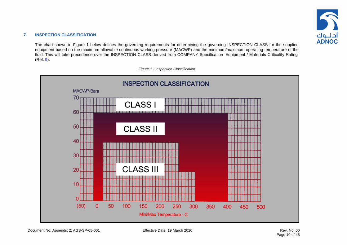
Document No: Appendix 2: AGS-SP-05-001 Effective Date: 19 March 2020 Rev. No: 00 Page 10 of 48
7. INSPECTION CLASSIFICATION
The chart shown in Figure 1 below defines the governing requirements for determining the governing INSPECTION CLASS for the supplied
equipment based on the maximum allowable continuous working pressure (MACWP) and the minimum/maximum operating temperature of the
fluid. This will take precedence over the INSPECTION CLASS derived from COMPANY Specification ‘Equipment / Materials Criticality Rating’
(Ref. 9).
Figure 1 - Inspection Classification
Document No: Appendix 2: AGS-SP-05-001 Effective Date: 19 March 2020 Rev. No: 00 Page 11 of 48
SECTION II – INSPECTION AND TESTING REQUIREMENTS
8. INSPECTION AND SURVEILLANCE REQUIREMENTS
This section defines the required minimum level of inspection for the supplied equipment in terms of three levels of inspection termed INSPECTION CLASS.
The SUPPLIER shall include the required design validation, manufacturing controls, materials inspection and testing in accordance with the specified INSPECTION CLASS when developing the relevant quality plans and inspection and test plans. The level of inspection required for each INSPECTION CLASS shall be in accordance with the minimum levels of inspection defined within Table 2 – Inspection Requirements.
The SUPPLIER shall submit certified reports of production tests and shop tests as soon as the tests are completed satisfactorily.
The COMPANY or CONTRACTOR reserves the right to inspect materials and workmanship at all stages of manufacture and to witness any or all tests. The SUPPLIER shall provide the COMPANY/CONTRACTOR with a copy of its Inspection and Test Plan (ITP) for review and inclusion of any mandatory COMPANY/CONTRACTOR inspection and witness points no later than 30 days after award and prior to the Pre-Inspection Meeting (PIM).
Table 2 – Inspection Requirements
Item No.
WORK, MANUFACTURING OR TEST ACTIVITY
Governing Document
INSPECTION CLASS
I II III
1 Planning and Control Activities
1.1 Quality Plan Review (ISO 9001, 8.1 and ISO 10005) R R R
1.2 Inspection and Test Plan (ITP)
(ISO 9001, 8.1 and ISO 10005, New Standard 8.1.7)
R R R
1.3 Kick-off and Pre-Inspection Meeting
(ISO 9001, 8.1 and ISO 10005, API 610, 8.1.1, 10.1.3, New Standard Appendix 2; Section 12.2.
W W
2 Design and Development Activities
2.1 Design verification review as required Review that manufacture is against accepted revision of documents.
(ISO 9001, 8.3) R R R
2.2 Weld procedure specification and procedure qualification records
(ANSI/API Std 610, Table 11) or as specified in New Standard, 3.70, 6.12.2.3, 6.12.2.5, 6.12.3.4, 8.2.2.1. Note: *For INSPECTION CLASS I only, “W” witnessed activity shall apply for
R* R R
Document No: Appendix 2: AGS-SP-05-001 Effective Date: 19 March 2020 Rev. No: 00 Page 12 of 48
Item No.
WORK, MANUFACTURING OR TEST ACTIVITY
Governing Document
INSPECTION CLASS
I II III
Super Duplex Stainless Steel (SDSS) and high nickel alloys.
2.3 Non-destructive examination procedures
(ASME BPVC V, Non-destructive examination in accordance with Appendix 2, Section 9.7 and 8.2.2.5.2, 8.2.2.9. Note: *For INSPECTION CLASS I only, “W” witnessed activity shall apply for Super Duplex Stainless Steel (SDSS) and high nickel alloys.
R* R R
2.4 Selection of raw materials used in the construction of pump parts. Compile Bill of Materials (BOM) for complete assembled unit.
(ANSI/API Std 610, Annex H) and as specified in New Standard, Annex G & P.
R R R
3 Control of External Supply
3.1 External supply scope, risk assessment and controls
(ISO 9001, 8.4) R R R
4 Materials and Component Manufacturing
4.1 Material certification and traceability
(ANSI/API Std 610, 6.12.1.8, 6.12.4.3 and 8.2.2.7, Tables H.2 and H.4 and New Standard, 3.43, 6.12.1.8 and 8.2.2.7)
S R R
4.2 Surfaces of castings (ANSI/API Std 610, 6.12.2.1) O S
4.3 Compliance of welding materials
(ASME BPVC.II Part C) S S
4.4 Fabrication
4.4.1 Baseplate manufacture (ANSI/API 610, 7.3 and New Standard, 7.3) flatness and coplanarity of baseplate equipment mounting pads
O S R
4.5 Inspection, testing and verification activities
(ANSI/API Std 610, 8.2 and 8.3 and New Standard, 8.2 and 8.3)
4.5.1 All welders have been qualified on approved welding procedures
(ANSI/API Std 610, Table 11) or as specified in New Standard, 6.12.3.1.
R R R
4.5.2 Weld repair procedure (excluding major weld repairs)
(ANSI/API Std 610, 6.12.2 and New Standard, 6.12.2)
R R R
Document No: Appendix 2: AGS-SP-05-001 Effective Date: 19 March 2020 Rev. No: 00 Page 13 of 48
Item No.
WORK, MANUFACTURING OR TEST ACTIVITY
Governing Document
INSPECTION CLASS
I II III
4.5.3 Weld repair procedure (major) maps and other specified documentation
(ANSI/API Std 610, 6.12.2.5 and New Standard, 6.12.2.5)
W W R
4.5.4 Inspection of major weld repairs
(ANSI/API Std 610, 6.12.2.3 and New Standard, 6.12.2.3, 6.12.2.5)
W O S
4.5.5 Non-destructive examination personnel performing non-destructive examinations are qualified and certified
in accordance with the requirements of Article 1, Section V of ASME BPVC and New Standard, 8.2.2.5, 8.2.2.9
R R R
4.5.6 Pressure casing inspection including all welds associated with the casing
(ANSI/API Std 610 Table 14 and New Standard, Table 14). Inspection timing (ANSI/API Std 610, 8.2.2.3)
O S R
4.6 Non-destructive examinations of component parts
(ANSI/API Std 610, 6.12.1.5 and 8.2.1.3) O R R
4.7 Positive Material Identification (PMI)
(ANSI/API Std 610, 8.2.2.8 and New Standard, 8.2.1.5, 8.2.2.8)
O S R
4.8 Verify that the heat treatments, including PWHT, have been performed
(ANSI/API Std 610, Table 11, New Standard 6.12.3.4b, 6.4.3.10)
R R R
4.9 Shaft and rotors (ANSI/API Std 610, 6.6, 9.3.3.1 and 9.3.12.2 d, Tables 17 and 19) and New Standards 6.6, 9.3.3.1.
O O R
4.10 Rotating component balancing
(ANSI/API Std 610, 6.9.4, 9.1.3.7 and 9.2.4 and New Standards, 6.9.4, 7.2.2f, 9.2.4, 9.2.2.5 and 9.3.5) Note: *For INSPECTION CLASS I only, “W” witnessed activity shall apply for >8 stages, or vertical pumps > 3m in length
R* R R
4.11 Wear rings and running clearance verification
(ANSI/API Std 610, Table 6 and New Standards, 6.6.15, 6.7.1, 6.7.4, 6.7.5, 6.10.1.2)
R R R
4.12 Cleanliness check prior to final assembly
(ANSI/API Std 610, 8.2.2.6 and New Standards 8.2.2.6)
O S S
4.13 Inspection and test equipment calibration certificates
R R R
4.14 Hydrostatic testing activities (ANSI/API Std 610, 8.3.2 and New Standards, 8.3.2)
W W O

Document No: Appendix 2: AGS-SP-05-001 Effective Date: 19 March 2020 Rev. No: 00 Page 14 of 48
Item No.
WORK, MANUFACTURING OR TEST ACTIVITY
Governing Document
INSPECTION CLASS
I II III
4.15 Auxiliary equipment testing (ANSI/API Std 610, 8.3.4.6 and New Standard 8.3.4.6)
W O R
4.16 Performance testing (ANSI/API Std 610, 8.3.3 and New Standards, 8.3.3)
W W O
4.17 NPSH or submergence testing
(ANSI/API Std 610, 8.3.4.3 and New Standards, 8.3.4.3)
W O O
4.18 Mechanical run testing (ANSI/API Std 610, 8.3.4.2 and New Standards, 8.3.4.2)
W O O
4.19 Sound level testing (ANSI/API Std 610, 8.3.4.5 and New Standard 8.3.4.5)
W O S
4.20 Complete unit testing (ANSI/API Std 610, 8.3.4.4 and New Standard 8.3.4.4)
W W O
4.21 Bearing housing resonance test
(ANSI/API Std 610, 8.3.4.7 and New Standard 8.3.4.7)
W O R
4.22 Structural resonance test (ANSI/API Std 610, 9.3.9.2 and New Standard 8.3.4.4)
W O R
4.23 Disassembly after testing (ANSI/API Std 610, 8.3.3.8 and New Standard 8.3.3.8)
W O S
4.24 Hydrodynamic bearing inspection after testing
(ANSI/API Std 610, 9.2.7.5 and New Standard, 9.2.7.5)
W O S
4.25 Surface preparation and painting
(ANSI/API Std 610, 6.12.2.1, 7.3.12, 8.4.2.4 and New Standards,7.3.12, 8.4.2.4, 9.3.8.3.3)
O O R
5 Release of Product or Service
5.1 Final Inspection. Verify conformity to PO including as applicable
5.1.1 Complete skid overall dimensions including holding down bolt hole and connection sizes and locations
Equipment General Arrangement Drawings and P&IDs (Accepted by COMPANY)
W W O
5.1.2 Couplings and guards (ANSI/API Std 610, 9.3.8.2.1, 7.2.1.3 and 7.2.3 and New Standards, 9.3.8.2.1)
W W O
5.1.3 Pump nameplate and rotation arrows
(ANSI/API Std 610, 6.13 and New Standards, 6.13)
W W O

Document No: Appendix 2: AGS-SP-05-001 Effective Date: 19 March 2020 Rev. No: 00 Page 15 of 48
Item No.
WORK, MANUFACTURING OR TEST ACTIVITY
Governing Document
INSPECTION CLASS
I II III
5.2 Loose ship items, spares and special tools as applicable
(ANSI/API Std 610, 7.6) W W O
5.3 Test moments My and Mz to be applied in combination to pump Suction and Discharge Nozzles (but not both nozzles simultaneously)
(ANSI/API Std 610, 7.3.21) W O R
5.4 Preparation of preservation, packing and storage (including loose ship items, spares and special tools)
(ANSI/API Std 610, 8.4 and New Standards, 8.4)
W O S
5.5 Final documentation review New Standards Appendix 3 “Information Requirements”
R R R
5.6 Inspection release note Purchase Order W W W

Document No: Appendix 2: AGS-SP-05-001 Effective Date: 19 March 2020 Rev. No: 00 Page 16 of 48
SECTION III – SHOP FABRICATION AND NDT
9. MATERIALS
9.1 General
9.1.1 Refer to ‘General Technical and Contractual Requirements’, Appendix 1 for general requirements relating to materials for all rotating equipment.
9.2 Manufacturing Data Records
9.2.1 The SUPPLIER shall keep the manufacturing data available for examination by the CONTRACTOR or his representative upon request. The manufacturing data shall be kept for at least 30 years.
9.3 PMI Testing
9.3.1 Positive Material Identification (PMI) testing is required for all alloy pressure-containing materials, piping components, and heat exchanger tubes.
9.3.2 The extent of PMI testing for all alloy parts shall be 100%, unless otherwise agreed with COMPANY. Any proposed reduction to the extent of PMI is subject to COMPANY approval.
9.3.3 Positive material identification shall be carried out in accordance with relevant COMPANY business unit standards. The SUPPLIER shall submit a report including copies of test instrument calibration certificate(s) to provide verification that the alloying element percentages of materials are in accordance with the proposed recognised material specification.
9.4 Pressure Containing Parts
9.4.1 All cast steel casings shall meet the requirements of ASME Section VIII, Division 1, Appendix 7.
9.4.2 Plates from which pressure-containing components are to be cut, forged, rolled or formed in any other manner, shall be subject to systematic ultrasonic inspection for laminations in accordance with ASTM A578-S9.
9.4.3 All welds in the casing, including those in piping attached to the casing, shall be examined radiographically or ultrasonically. Radiographic examination (RT) shall be performed in accordance with ASME V, Part. 2 and acceptance criteria shall be according to ASME VIII Div. 1, UW-51. UT shall be in accordance with ASME V, Part. 4 and acceptance criteria shall be in accordance with ASME VIII Div. 1, UW-53”. All non-destructive examination(s) shall be carried out after PWHT has been completed.
9.4.4 Permanent weld backing bars are unacceptable. Temporary backup bars must match the chemical composition of the base metal being welded. Welding filler metal shall be similar with respect to the chemistry, corrosion resistance, and physical properties of the base metal being welded. Temporary backing bars shall be removed before performing RT.
9.4.5 The ASME Welding Procedure Specifications (WPS), Procedure Qualification Records (PQR), and Welder Qualifications Records shall be available to the CONTRACTOR for review upon request or submitted for review and approval to CONTRACTOR as specified in the requisition. Welding of piping shall conform to relevant COMPANY business unit standards. Review of WPS, PQR and NDE procedures is mandatory for all equipment under INSPECTION CLASS I, sour service applications, duplex stainless steel and other superior CRA materials.

Document No: Appendix 2: AGS-SP-05-001 Effective Date: 19 March 2020 Rev. No: 00 Page 17 of 48
9.4.6 Destructive mechanical tests, including impact tests if required, shall be carried out on test blocks after all heat treatments have been performed, including those for possible repairs.
9.5 Welding Consumables
9.5.1 Welding consumables should be stored in their original unopened packaging in an area shielded from the elements. The SUPPLIER shall follow the manufacturer’s recommended procedures relating to storage, handling and re-conditioning of electrodes according to type. The following summary below provides guidelines as to the proper storage of stick electrodes, flux-cored wires, metal-cored wires, and solid wires (MIG wire and TIG cut length).
9.5.2 Low Hydrogen Electrodes (stick electrodes) shall be classified per AWS as EXX15-X, EXX16-X, and EXX18-X. These electrodes must be dry to perform adequately. Manufacturers typically supply these electrodes in hermetically sealed containers which provide proper protection under good storage conditions. Open containers of low hydrogen electrodes must be stored in a cabinet at 120°C – 150°C.
9.5.3 Moisture resistant coatings (“R” designation) have higher resistance to moisture pick up but should be stored in the same manner. The “R” designation allows for more exposure time before the electrode needs to be re-dried. It is recommended that low hydrogen electrodes without the “R” designation be supplied twice per shift to stay below the permissible 4 hours of exposure. AWS D1.1 Structural Welding Code Table 5.1 specifies allowable atmospheric exposure which can be seen below.
9.5.4 Low hydrogen electrodes may be re-dried if they exceed exposure limits following the manufacturers recommended procedures. It is critical to avoid drying electrodes at temperatures above those recommended. Also, longer hold times at lower temperatures is not equivalent as holding the right temperature for the specified time. For additional information on storing and re-drying low-hydrogen electrodes read Storing and Re-drying Low Hydrogen Electrodes.
9.5.5 Where non-low hydrogen electrodes are exposed to humid air for long periods of time the welding characteristics may be affected. If moisture appears to be causing problems, it is recommended to store open containers in cabinets heated to 38°C – 49°C.
9.5.6 The manufacturers shall supply metal cored and fluxed wires in packages that provide proper protection when stored indoors with a relative humidity not higher than 70%. It is important to store in areas that minimize temperature variations to avoid condensation on the consumables.
9.5.7 Materials shall be stored in the original, unopened packaging in a covered dry location until it’s time to use. For applications in which the weld metal hydrogen must be kept under a specific amount (usually 8mL/100g H2 or lower) only use product supplied in hermetically sealed packaging.
9.5.8 For storage of FCAW and MCAW wires that have been opened the recommendations below shall be followed:-
a) Use within a week of opening original packaging b) Do NOT expose open wires to damp conditions or extreme temperature changes c) When not in use place wire back in its original packaging (bag and box) and seal as best as
possible d) Discard any wire that has been exposed to moisture and shows signs of rust.
e) Flux-cored wire should not be left out in the open when not in used as it is prone to moisture pick up.
9.5.9 Solid wires and GTAW electrodes are not as susceptible to moisture pick up, however they shall be
stored in similar fashion as noted above. Store in unopened container until it is time to use. Store in
Document No: Appendix 2: AGS-SP-05-001 Effective Date: 19 March 2020 Rev. No: 00 Page 18 of 48
areas protected from rain and snow, avoid severe fluctuations in temperature and protect from condensation. Discard if wire shows rust on its surface.
9.5.10 Reference shall be made to AWS D1.1/D1.1M: 2015 Structural Welding Code – Steel.
9.6 Weld Procedure Specifications, Weld Procedure Qualification Records and Weld Maps
9.6.1 Welding
Fabrication and welding shall be carried out in accordance with ASME BPVC, Section IX. The minimum requirements relating to shop fabrication including WPS, WPQR and welder qualifications, PWHT, NDT procedures, NDT operator qualifications, impact testing, sour service requirements and weld repairs are detailed in the following sections 9.6.2 to 9.6.8.
9.6.2 Weld Procedure Specification and Weld Procedure Qualification Records
The SUPPLIER shall submit a WPS and associated WPQR for each different weld type forming part of the fabricated sections of the equipment or package. The SUPPLIER shall provide detailed weld map(s) to clearly identify each weld and to show the location and type of the proposed weld referencing the Weld Procedure (WPS) and associated Weld Procedure Qualification Record (WPQR) in each case.
9.6.3 Welder Qualification
Each welder shall be qualified to perform the required welding process using a qualified and approved Weld Procedure Specification (WPS). The welder’s name, welder identification no., WPS number, weld location and NDT method used shall be recorded on a separate weld map for each fabricated item in accordance with the applicable code requirements. Shop fabrication procedures including WPS, WPQRs, WQs, NDE procedures, NDE reports and associated weld maps will be subject to approval by a nominated third-party inspection authority when specified in the purchase order.
9.6.4 Post Weld Heat Treatment
Post Weld heat Treatment (PWHT) shall be carried out in accordance with the applicable WPS and WPQR. Heat treatment records shall be submitted within the Manufacturing Record Book (MRB) which shall identify the time chart of measured temperature and duration of heat treatment.
9.6.5 NDT Operator Qualifications
Qualification and certification of all NDT operators shall be according to Recommended Practice No. SNT-TC-1A & CP-189 Personnel Qualification and Certification in Non-Destructive Testing or EN ISO 9712. Operators shall be ASNT Level 1, 2 or 3 in accordance with the ASME V Article 1 requirements for each NDE process, material/weld thickness, weld location and type of weld under examination.
9.6.6 Impact Testing
Impact testing shall be carried out on all welds in low temperature service at the Minimum Design Metal Temperature (MDMT) in accordance with ASME Code Section VIII, Division 1, UG-20(b), UCS-66(a), UCS66(b) and UCS-68(c). The Charpy V notch energy values obtained shall satisfy the minimum impact test values specified within ASME BPVC, Section VIII Division 1, UCS-67 ‘Impact Tests of Welding Procedures’. Impact testing mandatory for sour service applications irrespective of MDMT indicated on datasheets. If the MDMT is greater than -15°C, the required test temperature(s) and impact energy values shall be mutually agreed with COMPANY at the proposal stage.

Document No: Appendix 2: AGS-SP-05-001 Effective Date: 19 March 2020 Rev. No: 00 Page 19 of 48
All materials in low temperature service shall undergo impact testing at or below the specified MDMT. The original material certificates shall record full details of the Charpy impact energy values obtained in accordance with BS EN10204:2004.
9.6.7 Sour Service Requirements
All materials intended to be in contact with sour liquids or H2S shall conform in all respects to NACE standard MR0175/ISO 15156 or NACE MR0103/ISO 17945 and references therein.
9.6.8 Major Weld Repairs
Prior to performing any weld repair on wrought material or any major weld repair on cast material, the SUPPLIER shall submit details of the proposed weld repairs for COMPANY approval, along with the relevant WPS and PQR. In the event of major weld repairs being required, weld repair maps showing location and major dimensions of weld repair cavities, applicable qualification records, drawings, photographs, heat treatment procedures, further NDE procedures and detailed records of all repairs shall be submitted to COMPANY for review and approval.
No repairs/modifications of any type (minor or major) shall be done after equipment has been released for shipment. Both major and minor repairs shall be reported to COMPANY.
a) For weld repairs on pressure containing parts, the following shall apply:
1. COMPANY approval shall be obtained before any major weld repair is carried out. 2. All repairs shall meet the inspection requirements and acceptance standards of the original
material. Major repairs shall be inspected by the COMPANY which shall be notified at least one week in advance of starting the repair.
3. Repair procedures for major* weld repairs are subject to approval of the COMPANY. Repair welder qualifications shall be reviewed and approved by CONTRACTOR.
4. The total quantity of weld metal deposited shall be less than 10% of the mass of the casting. This shall be determined by weighing the casting before and after weld repairs. Where the quantity of weld repair exceeds 10% of the mass of the casting, the repair shall not be acceptable.
5. Weld repairs shall be suitably heat-treated if this is specified in the relevant material specification and/or manufacturing standard. A major* weld repair shall always be followed by a heat treatment.
6. Details of all major* weld repairs and the heat treatment shall be recorded and reported to the COMPANY.
*NOTE: A weld repair of a casting is defined as "major" if a repair weld has a depth of more than 50% of the wall thickness or has a length of more than 150 mm in one or more directions, or if the total surface area of all repairs on the casting exceeds 10% of the total casting surface area. A weld repair necessitated by a leaking pressure test is also classed as "major".
b) The repair of leaks and defects in pressure-containing castings is not allowed by peening or burning-in, or by impregnation with plastics or cement compounds. Repair by welding or by plugging shall be undertaken only when permitted by the material specification and/or manufacturing standard, and then, only in accordance with the procedures detailed in this and relevant specifications (see d below).
c) Weldable grades of castings may be repaired by welding subject to the following criteria:
1) Criteria as per a. above.
2) The repair welding procedures and the repair welder's qualifications shall be in accordance with ASTM A488 or ASME Section IX.

Document No: Appendix 2: AGS-SP-05-001 Effective Date: 19 March 2020 Rev. No: 00 Page 20 of 48
3) Other criteria may exist in applicable Specifications.
d) Repair by Plugging
1. The need for repair by plugging shall be reported to COMPANY before any repair is carried out.
2. Nodular iron may be repaired by plugging within the limits specified in ASTM A395. The drilled holes for plugs shall be carefully examined by dye penetrant to ensure removal of all defective material.
3. All necessary repairs by plugging not covered by ASTM shall be subject to approval by COMPANY.
4. Details of all repairs by plugging shall be recorded and included in the manufacturing report.
e) When defects are found which necessitate a major* weld repair, the casting shall be inspected to the next more severe inspection class unless the initial inspection was already the highest.
9.7 Non-Destructive Examination Methods
The extent of Non-Destructive Examination (NDE) to be applied to the equipment/package is defined in Table 7 – Inspection & NDT Minimum Requirements included in Section 11. The procedures and acceptance criteria are given in the following paragraphs.
Prior to starting fabrication activities, the SUPPLIER shall submit NDT procedures to COMPANY for approval.
9.7.1 Radiographic Examination (RT)
a) RT of castings shall be performed in accordance with ASME Section VIII, Division 1, Appendix 7. Critical sections of each casting (including regions of abrupt section changes, weld ends, areas adjacent to feeders and raisers) shall be fully radiographed. Where such sections cannot be radiographed, UT shall be substituted (also in accordance with ASME Section VIII, Division 1, Appendix 7). Acceptance standards for castings shall be in accordance with Table 3 below.
The SUPPLIER shall submit, for COMPANY’S approval, details of the critical sections proposed to receive RT/UT. All personnel performing and interpreting the results of the various NDE techniques shall possess appropriate nationally recognized qualifications.
b) RT of welds shall be in accordance with ASME Section VIII, Division 1, UW-51. Coverage shall be 100 percent.
Table 3 – Acceptance Criteria for Castings
SECTION THICKNESS (mm) <25 25 TO 50 51 (and above)
Defect Category Degree of Severity
A Gas Porosity 2 3 3
B Sand and Slag 2 3 3
C Shrinkage (All Types) 2 2 2
D, E Cracks and Hot Tears Not Acceptable
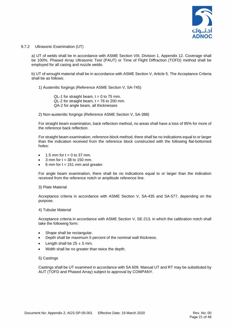
Document No: Appendix 2: AGS-SP-05-001 Effective Date: 19 March 2020 Rev. No: 00 Page 21 of 48
9.7.2 Ultrasonic Examination (UT)
a) UT of welds shall be in accordance with ASME Section VIII, Division 1, Appendix 12. Coverage shall be 100%. Phased Array Ultrasonic Test (PAUT) or Time of Flight Diffraction (TOFD) method shall be employed for all casing and nozzle welds.
b) UT of wrought material shall be in accordance with ASME Section V, Article 5. The Acceptance Criteria shall be as follows:
1) Austenitic forgings (Reference ASME Section V, SA-745)
QL-1 for straight beam, t = 0 to 75 mm. QL-2 for straight beam, t = 76 to 200 mm. QA-2 for angle beam, all thicknesses
2) Non-austenitic forgings (Reference ASME Section V, SA-388)
For straight beam examination, back reflection method, no areas shall have a loss of 95% for more of the reference back reflection. For straight beam examination, reference block method, there shall be no indications equal to or larger than the indication received from the reference block constructed with the following flat-bottomed holes:
1.5 mm for t = 0 to 37 mm.
3 mm for t = 38 to 150 mm.
6 mm for t = 151 mm and greater. For angle beam examination, there shall be no indications equal to or larger than the indication received from the reference notch or amplitude reference line.
3) Plate Material
Acceptance criteria in accordance with ASME Section V, SA-435 and SA-577, depending on the purpose.
4) Tubular Material
Acceptance criteria in accordance with ASME Section V, SE-213, in which the calibration notch shall take the following form:
Shape shall be rectangular.
Depth shall be maximum 5 percent of the nominal wall thickness.
Length shall be 25 ± 5 mm.
Width shall be no greater than twice the depth.
5) Castings
Castings shall be UT examined in accordance with SA 609. Manual UT and RT may be substituted by AUT (TOFD and Phased Array) subject to approval by COMPANY.
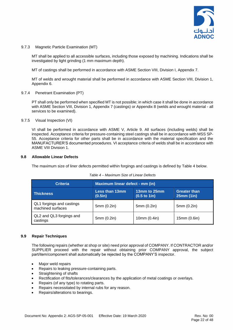
Document No: Appendix 2: AGS-SP-05-001 Effective Date: 19 March 2020 Rev. No: 00 Page 22 of 48
9.7.3 Magnetic Particle Examination (MT)
MT shall be applied to all accessible surfaces, including those exposed by machining. Indications shall be investigated by light grinding (1 mm maximum depth).
MT of castings shall be performed in accordance with ASME Section VIII, Division I, Appendix 7.
MT of welds and wrought material shall be performed in accordance with ASME Section VIII, Division 1, Appendix 6.
9.7.4 Penetrant Examination (PT)
PT shall only be performed when specified MT is not possible; in which case it shall be done in accordance with ASME Section VIII, Division 1, Appendix 7 (castings) or Appendix 8 (welds and wrought material - all services to be examined).
9.7.5 Visual Inspection (VI)
VI shall be performed in accordance with ASME V, Article 9. All surfaces (including welds) shall be inspected. Acceptance criteria for pressure-containing steel castings shall be in accordance with MSS SP-55. Acceptance criteria for other parts shall be in accordance with the material specification and the MANUFACTURER’S documented procedures. VI acceptance criteria of welds shall be in accordance with ASME VIII Division 1.
9.8 Allowable Linear Defects
The maximum size of liner defects permitted within forgings and castings is defined by Table 4 below.
Table 4 – Maximum Size of Linear Defects
Criteria Maximum linear defect - mm (in)
Thickness Less than 13mm (0.5in)
13mm to 25mm (0.5 to 1in)
Greater than 25mm (1in)
QL1 forgings and castings machined surfaces
5mm (0.2in) 5mm (0.2in) 5mm (0.2in)
QL2 and QL3 forgings and castings
5mm (0.2in) 10mm (0.4in) 15mm (0.6in)
9.9 Repair Techniques
The following repairs (whether at shop or site) need prior approval of COMPANY. If CONTRACTOR and/or SUPPLIER proceed with the repair without obtaining prior COMPANY approval, the subject part/item/component shall automatically be rejected by the COMPANY’S inspector.
Major weld repairs
Repairs to leaking pressure-containing parts.
Straightening of shafts
Rectification of fits/tolerances/clearances by the application of metal coatings or overlays.
Repairs (of any type) to rotating parts.
Repairs necessitated by internal rubs for any reason.
Repairs/alterations to bearings.
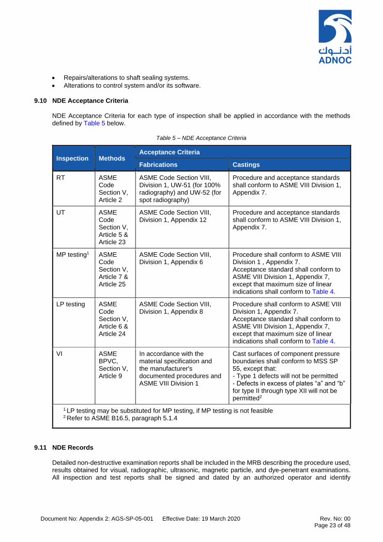
Document No: Appendix 2: AGS-SP-05-001 Effective Date: 19 March 2020 Rev. No: 00 Page 23 of 48
Repairs/alterations to shaft sealing systems.
Alterations to control system and/or its software.
9.10 NDE Acceptance Criteria
NDE Acceptance Criteria for each type of inspection shall be applied in accordance with the methods defined by Table 5 below.
Table 5 – NDE Acceptance Criteria
Inspection Methods Acceptance Criteria
Fabrications Castings
RT ASME Code Section V, Article 2
ASME Code Section VIII, Division 1, UW-51 (for 100% radiography) and UW-52 (for spot radiography)
Procedure and acceptance standards shall conform to ASME VIII Division 1, Appendix 7.
UT ASME Code Section V, Article 5 & Article 23
ASME Code Section VIII, Division 1, Appendix 12
Procedure and acceptance standards shall conform to ASME VIII Division 1, Appendix 7.
MP testing1 ASME Code Section V, Article 7 & Article 25
ASME Code Section VIII, Division 1, Appendix 6
Procedure shall conform to ASME VIII Division 1 , Appendix 7. Acceptance standard shall conform to ASME VIII Division 1, Appendix 7, except that maximum size of linear indications shall conform to Table 4.
LP testing ASME Code Section V, Article 6 & Article 24
ASME Code Section VIII, Division 1, Appendix 8
Procedure shall conform to ASME VIII Division 1, Appendix 7. Acceptance standard shall conform to ASME VIII Division 1, Appendix 7, except that maximum size of linear indications shall conform to Table 4.
VI ASME BPVC, Section V, Article 9
In accordance with the material specification and the manufacturer's documented procedures and ASME VIII Division 1
Cast surfaces of component pressure boundaries shall conform to MSS SP 55, except that: - Type 1 defects will not be permitted - Defects in excess of plates “a” and “b” for type II through type XII will not be permitted2
1.LP testing may be substituted for MP testing, if MP testing is not feasible 2.Refer to ASME B16.5, paragraph 5.1.4
9.11 NDE Records
Detailed non-destructive examination reports shall be included in the MRB describing the procedure used, results obtained for visual, radiographic, ultrasonic, magnetic particle, and dye-penetrant examinations. All inspection and test reports shall be signed and dated by an authorized operator and identify

Document No: Appendix 2: AGS-SP-05-001 Effective Date: 19 March 2020 Rev. No: 00 Page 24 of 48
components tested, location, heat-treated condition, and other requirements per Project specifications. The above reports shall be available for inspection at the SUPPLIER’s works by CONTRACTOR or by COMPANY upon giving due notice of inspection at each stage of manufacture/fabrication.

Document No: Appendix 2: AGS-SP-05-001 Effective Date: 19 March 2020 Rev. No: 00 Page 25 of 48
10. MATERIAL CERTIFICATION AND TRACEABILITY
10.1 Material Certificates
10.1.1 The SUPPLIER shall furnish material certification for the supplied equipment and materials in accordance with Table 6 – Material Certification . Material inspection certificates shall be provided in accordance with Table 1 of ISO 10474:2013 or Table A.1 of EN 10204:2004.
Table 6 – Material Certification for Centrifugal Pump Parts
EQUIPMENT COMPONENT / MATERIAL CERTIFICATE TYPE
as per BSEN10204:2004
All pressure retaining and stress bearing parts including
attachments (casing, end covers & nozzles, balance line
& casing bolts)
3.1
Rotating components (shaft, impeller, sleeves etc.)
Internals (inner barrel in case of BB5, guide channels etc.)
3.1
Shaft seals, bolting, All other auxiliary piping, valves,
flanges & connections
3.1
Structural steelwork, baseplates 3.1
Diffusers and other static metallic parts inside the pump 3.1
Process / casing gaskets 2.2
Non-metallic materials 2.2
Wear rings, throttle bushings 2.2
Notes
1) Type 3.2 certification shall be provided for materials subject to weld overlay or special metallurgy such as SSDS, Inconel, Monel, Hastelloy etc. or where application is considered critical.
2) For other metallic parts including base plates and structural steel components, Type 3.1 certification is acceptable.
3) Type 2.2 certification acceptable for non-metallic components and wear rings.
10.1.2 The SUPPLIER shall provide either original material certificates or true verified copies of the original material certificate(s) or mill certificates which shall contain the original “date stamp” and verifying signature of the SUPPLIER’s QA/QC inspector. Unverified copies of certificates are not acceptable.
10.1.3 Stockist certificates are not acceptable unless they are accompanied by copies of the original works certificate.
10.1.4 The certificates shall be in English language or shall include an English translation. Metric units shall be used. The certificates shall be complete, legible and suitable for subsequent microfilming and photocopying. The certificates, combined if necessary, shall represent the material in the final condition.

Document No: Appendix 2: AGS-SP-05-001 Effective Date: 19 March 2020 Rev. No: 00 Page 26 of 48
10.1.5 The different types of material certificate are defined in accordance with BSEN 10204:2004 or ISO 10474:2013.
10.2 Material Traceability and Marking
10.2.1 All pressure retaining castings shall have the material designation embossed or engraved on each part.
10.2.2 Marking is required for all pressure casings and for component parts requiring Type 3.1 or 3.2 material certificates. Parts with a wall thickness in excess of 5 mm, except those items manufactured from austenitic stainless steel or from nickel alloys, shall be legibly marked by hard-die stamping on to a painted background at a place clearly visible later. Pipes should be marked at a point approximately 250 mm from one end.
10.2.3 Only low-stress stamps (dot-type or round-nosed with minimum radius of 0.25 mm) shall be used for hard-die stamping.
10.2.4 For items manufactured from austenitic stainless steel or nickel alloys, and for items with a wall thickness of 5 mm or less, the marking shall be applied by stencil using a water-insoluble ink which contains no injurious substances such as metallic pigments, sulfur, sulfides or chlorides which could attack or harmfully affect the material.
10.2.5 The stamping/marking shall include:
Material MANUFACTURER’S symbol and, where applicable, the independent inspector's symbol; these symbols shall be identical to the symbols on the material certificate.
Material identification.
Heat, charge or batch number to relate to the material certificate.
Heat treatment symbol or code, where applicable.
Non-destructive testing symbol or code, where applicable.
Size and schedule, where applicable.
Hydrostatic test pressure, where applicable.
Note: Where the size of the item does not permit complete marking, the above identification marks may be substituted by a unique code which is fully traceable to the material certificate for the item.

Document No: Appendix 2: AGS-SP-05-001 Effective Date: 19 March 2020 Rev. No: 00 Page 27 of 48
11. NDT AND MATERIAL CERTIFICATION REQUIREMENTS
The following table defines the minimum levels of NDT and material certification that shall apply for the
components of API 610 Centrifugal Pumps.
Table 7 – Inspection & NDT Minimum Requirements
Equipment Component Required Inspection (Notes)
Casing (cast), casing – forged / wrought including inner barrel, diaphragms, guide channels and other pressure retaining, static components as applicable.
VI, RT or UT and MT or PT (Notes 2 & 4)
Welds - full penetration welds including aux. pressure piping
VI, RT or UT and MT or PT (Note 3)
Welds - fillet welds, flange surfaces, gasket sealing surfaces
VI, MT or PT, spot RT
Shaft VI, UT and MT or PT (Note 2 & 4)
Impellers VI, RT or UT and MT or PT (Notes 2 & 4)
Shaft sleeves, balance piston, bearing housing, bearings
MT or PT, and VI
Shaft seals, labyrinths VI
Notes
1. VI = Visual Examination; MT = Magnetic Particle Examination; PT = Liquid Penetrant Examination (fluorescent); RT = Radiographic Examination; UT = Ultrasonic Examination (phased array). Hardness testing, impact testing as applicable. All Radiographs shall be digitized and cross reference to part numbers and NDE records shall be ensured while submitting manufacturing data book.
2. Both raw material and finished component requires inspection (as applicable).
3. For LO and utility auxiliary systems, RT/UT shall be 10%. For process connections RT/UT shall be 100%.
4. 100% RT or UT shall be applied for pump casing, shaft and impellers.

Document No: Appendix 2: AGS-SP-05-001 Effective Date: 19 March 2020 Rev. No: 00 Page 28 of 48
SECTION IV – SHOP TESTING AND SITE ACCEPTANCE TESTS
12. FACTORY INSPECTION AND TESTING
12.1 General
12.1.1 Inspection and testing shall comply with this specification, datasheets and requisition. COMPANY reserves the right to assign a third-party inspector to attend/observe/witness any or all the inspection and testing activities at SUPPLIER’S or SUB-SUPPLIER’S works. Testing requirements shall be construed to apply for each item. No sample or random testing is allowed.
12.1.2 Only measuring equipment that can be demonstrated to have been previously calibrated satisfactorily and still be within its documented calibration period (interval) shall be used for inspection and testing.
12.1.3 The SUPPLIER shall notify all his SUB-SUPPLIERS of inspection and testing requirements in accordance with the submitted ITP and related controlling specifications.
12.1.4 Tests other than witnessed and observed may also be attended by CONTRACTOR or his representative. COMPANY and/or CONTRACTOR or their representatives shall not be barred from attending a "Non-Witnessed" test and evaluating its outcome. Any test noted as "Required" without any further definition shall be understood to be "Non-Witnessed".
12.1.5 Sub-orders issued by SUPPLIER to SUB-SUPPLIERS shall include the relevant specifications provided by the PURCHASER where applicable to the materials and equipment to be purchased.
12.2 Pre-Inspection Meeting
12.2.1 A Pre-Inspection Meeting shall be held at the SUPPLIER’s works prior to start of manufacturing of all compressors. Additional PIMs may be held at the SUB-SUPPLIER’s works where necessary dependent on scope of work of the package. The purpose of the Pre-Inspection Meeting (PIM) is to review the extent of the SUPPLIER’s quality assurance, design activities, shop inspection and testing, which shall be confirmed prior to manufacture. As a minimum it shall include, but need not be limited to the following main items in accordance with Table 2 – Inspection Requirements:-
a) Planning and Control Activities
b) Design and Development Activities
c) Control of External Supply
d) Materials and Component Manufacturing
e) Fabrication
f) Inspection, Testing and Verification Activities
g) Release of Product or Service
h) Final Inspection. Verify conformity to PO including as applicable
The test procedures to be used for each test shall be submitted for review by COMPANY at least 6
weeks prior to the scheduled test activity.
12.3 Hydrotest Test
12.3.1 For cast pressure components, the duration of the hydrostatic test shall be a minimum of 30 minutes or time suitable for performing inspection whichever is higher.
12.3.2 For all stainless steels, the chloride content in the test water shall not exceed 30 ppm.
Document No: Appendix 2: AGS-SP-05-001 Effective Date: 19 March 2020 Rev. No: 00 Page 29 of 48
12.3.3 For carbon and alloy steels, the chloride content of water used for hydrostatic test shall not exceed 50 ppm chlorides. If water with a chloride content of between 30ppm and 50ppm is used, the component shall be drained and rinsed with water containing no more than 2ppm chlorides and thoroughly dried.
12.4 Control System Simulated Test (iFAT)
Control system panels containing operator HMI, controls software (PLCs), power supplies (PSUs), ventilation fans and associated 19” equipment racks shall undergo simulated iFAT prior to main equipment performance test.
This test shall include but not limited to:-
Simulate all alarms and trips
Start-up sequence
Shutdown sequence
Different modes of operation
Mimic displays (HMI)
All peripherals (printers, servers, etc...)
Control functions
Protection and ESD logic
12.5 Performance Test
12.5.1 A performance test shall be carried out on each pump in accordance with COMPANY approved job specific test procedures. During performance testing, original internal clearances and tolerances shall be maintained.
12.5.2 The SUPPLIER shall guarantee the performance of the equipment in accordance with AGES-SP-05-001, Centrifugal Pumps (API 610) Specification and according to the test tolerances specified within API 610 11th Edition.
12.6 Mechanical Running Test
12.6.1 The mechanical run test (MRT) shall be carried out for each pump over a minimum duration of four (4) hours after temperature stabilization. A test bed oil sample shall be taken before and after each mechanical run test as applicable. An analysis of each oil sample shall be included in the test report.
12.6.2 During this test, the lubricating oil and seal oil temperature shall be held for a minimum period of 60 minutes at the temperature corresponding to the minimum allowable viscosity, and for 60 minutes at the temperature corresponding to the maximum allowable viscosity. Oil pressures and temperatures and bearing temperatures shall be measured and recorded throughout the test.
12.6.3 Internal rubs causing clearances that exceed 50% of the tolerances specified by the SUPPLIER’S design documents shall be cause for design review, rectification of reasons causing rubs and re-test.
12.6.4 Spare coupling, seals and bearings shall be installed during the mechanical run test of the spare rotor or the spare rotor bundle.
12.7 Complete Unit Test
12.7.1 Where specified in the equipment datasheets, the complete package including all ancillary components and systems such as lube/seal oil systems, seals, couplings, control panel(s) shall be used during the complete unit test and the machinery train should be run for test purposes. Such a test, if done at MANUFACTURER’s facility, shall be declared to be a string test.

Document No: Appendix 2: AGS-SP-05-001 Effective Date: 19 March 2020 Rev. No: 00 Page 30 of 48
12.7.2 A complete unit test (or string test) is required when specified or when the discharge pressure exceeds 100 bar(g) or when the driver rating exceeds 1000 kW.
12.7.3 If a complete unit test is specified, only the motor driven unit shall be subject to the complete unit test requirement. Motor driven pump complete unit tests shall be performed with the job lube oil system, job seals and seal system.
12.7.4 Unless otherwise specified, a complete unit test for first unit (for identical pumps) shall be performed and, if successful, then the driver and pump (shaft line) only is to be tested for the other identical units.
12.7.5 A Complete Unit Test (CUT) is required when Hydraulic Power Recovery Turbine (HPRT) or variable speed torque convertor are part of the package.
12.7.6 If first unit complete unit test was not satisfactory (i.e. fails in terms of operating and mechanical performance) then all units shall undergo a complete unit test. This test is in addition to the individual equipment/component test.
12.8 Sound Level Test
12.8.1 Sound level test shall be performed on the equipment in accordance with ISO 3744 and ISO3746 to meet the limits specified in the equipment datasheets.
12.9 Auxiliary Equipment Tests
12.9.1 All control panels shall undergo shop radio frequency interference (RFI) and “burn-in” tests.
12.9.2 All lube systems shall undergo a 4 hours mechanical run test.
Document No: Appendix 2: AGS-SP-05-001 Effective Date: 19 March 2020 Rev. No: 00 Page 31 of 48
13. SITE ACCEPTANCE TESTING
The EPC CONTRACTOR shall carry out site acceptance test (SAT) based on following guidelines under the supervision of the SUPPLIER. The SUPPLIER shall develop various operating scenarios and agree the acceptance procedures and acceptance criteria during project execution. All such criteria must be fulfilled during SAT. A preliminary version of the proposed SAT procedure shall be issued by the SUPPLIER with the Proposal. Agreement on a formal list of SAT acceptance criteria shall be established between SUPPLIER, CONTRACTOR and COMPANY PRIOR to Purchase Order Award. This agreed list of criteria will form part of the Purchase Order Agreement. The details of the SAT Procedure can be developed post-award, but the list of acceptance criteria parameters shall not be revised without written mutual agreement between SUPPLIER, CONTRACTOR and COMPANY. The site acceptance test (SAT) must fully demonstrate that the equipment performs at site in a satisfactory manner and is able to meet all specified contractual requirements. The site acceptance test procedure shall be submitted for COMPANY review/comments in advance of commencement of test program. Prior to overall plant performance/reliability/acceptance test, an uninterrupted 72 hours SITE ACCEPTANCE TEST is to be performed for each complete machinery package and its auxiliary system(s). During this test, CONTRACTOR and SUPPLIER shall demonstrate that the system including driven machinery, drivers, control and auxiliary systems (lube, seal systems) functions (meeting the contractual performance requirements including vibrations, bearing pad temperatures etc.) throughout the agreed operating range.
The intention of the test is to verify the equipment performance at site against the original expected and factory tested performance. The measured absorbed power, flow and head shall be within agreed tolerances based on the specified design parameters and required utilities. After collection of field data, the OEM shall verify site performance against certified / rated conditions and provide as-built performance curves. If performance falls short, SUPPLIER shall make good and resolve deficiencies to satisfaction of COMPANY.
The CONTRACTOR shall submit Site Acceptance Test (SAT) procedures for COMPANY review prior to commencement of the tests.
At the time of the above tests, all insurance/capital spares and commissioning spares shall be available at site. Equipment shall not be released for testing/operation unless these spares are available at site. Any spare parts issued by COMPANY to the CONTRACTOR shall be replaced with new spares by the CONTRACTOR.
During the above tests, no control systems shall be bypassed and no alarm and/or trip conditions shall arise. If such a condition arises, the tests shall be considered as not successful and shall be repeated at a time agreed with COMPANY. Details of test measurement instrumentation to be used including accuracy limits, proposed test instrument locations and relevant calibration records shall be reviewed and mutually agreed between SUPPLIER and EPC CONTRACTOR prior to testing.
After satisfactory completion of SAT, the COMPANY representative shall sign the 'System Acceptance Note’, which shall mean acceptance of the system for operation and the subsequent sustained performance test.
1. The SUPPLIER’s representative must be available on site during the SAT period to coordinate and resolve any unplanned deficiencies. During this, OEM shall be present (like seal supplier, motor and VFD system supplier, gearbox supplier etc. when required and where applicable, etc.)

Document No: Appendix 2: AGS-SP-05-001 Effective Date: 19 March 2020 Rev. No: 00 Page 32 of 48
2. Duration for SAT shall be 72 hours of smooth running, after obtaining confirmation from the COMPANY that the pump has attained a steady and stable operation conditions following the commissioning and prior to starting the test run. It is imperative that the pump train components, auxiliaries, calibration of all instruments, setting of vibration probes is done satisfactorily during this period. This shall be in SUPPLIER scope. Machine monitoring system and data gathering system shall be in place and SUPPLIER shall ensure functional requirements of the same. Calibration records of all the measuring instruments meeting with norms of the test shall be in place. If a permanent machine monitoring system is not applicable, portable instruments shall be used to record the vibration parameters.
3. Pump performance evaluation: The analysis of the guarantee point(s) shall be done through the
capture of three (3) test points (one at the rated flow, one at the normal flow and one at the MCF. If permanent flow instruments are not available at site, CONTRACTOR shall make necessary arrangements (such as clamp type ultrasonic flow meters to avoid modifications at site).
4. SAT is expected to be carried out in an uninterrupted manner. Any failure /trip will result in restarting
the train ignoring the earlier clocked hours. During site acceptance tests:
a. Operate the pump at the rated point at least 4 hours. b. If multiple operating points are indicated (such as normal, minimum etc.), operate at those points
for 2 hours each as allowed by operations. c. Operate the pump for one hour with maximum oil temperatures where forced lube oil system is
supplied (by adjusting TCV/stopping fans in LO system, as possible) d. Start the pump with open discharge valve. e. Pump on minimum continuous flow for a period of 8 hours f. Mark the site operating points on the performance curve as FINAL as built. g. Seal leakages shall be below 75% of maximum guaranteed leakage rates. h. Absorbed power shall be within API tolerances across allowable operating range (max. 4%).
5. SUPPLIER shall prepare procedures indicating description of test, data collection points and their
acceptance criteria and shall include various scenarios such as starting, normal stop, emergency shutdown, control system functionality, auxiliary systems functionality etc.
6. The following tables summarize the mechanical acceptance criteria for the centrifugal pump, the gearbox (if any), electrical motor and the baseplate which are applicable to the whole complete unit string test (including site acceptance test). Any project specific requirements must be agreed as part of the site acceptance test procedure.
Table 8 – Centrifugal Pump, Gearbox and Drive Motor Vibrations
Centrifugal pump Radial Vibrations (μm pk to pk unfiltered)
Gearbox High / Low speed shaft radial Vibrations (μm pk to pk unfiltered) where used
Electric motor Radial vibrations (μm pk to pk unfiltered)
As per ISO 10816-3 Zone boundary A/B OR 50 OR 66% of alarm values whichever is less
25.4 x √(12000/N) x √2 OR 38.1 OR 66% of alarm limit chosen based on ISO 7913 / ISO 10816
50 OR 66% of alarm limit chosen based on ISO 7913 / ISO 10816
Any stable discrete, non-synchronous vibration exceeding 20% of the allowable vibration as defined in Table 8 above shall be cause of rejection of the package. Any unstable non-synchronous vibration shall be cause of rejection of the package.
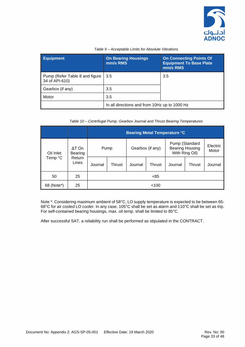
Document No: Appendix 2: AGS-SP-05-001 Effective Date: 19 March 2020 Rev. No: 00 Page 33 of 48
Table 9 – Acceptable Limits for Absolute Vibrations
Equipment On Bearing Housings mm/s RMS
On Connecting Points Of Equipment To Base Plate mm/s RMS
Pump (Refer Table 8 and figure 34 of API-610)
3.5 3.5
Gearbox (if any) 3.5
Motor 3.5
In all directions and from 10Hz up to 1000 Hz
Table 10 – Centrifugal Pump, Gearbox Journal and Thrust Bearing Temperatures
Bearing Metal Temperature °C
Oil Inlet Temp °C
ΔT On Bearing Return Lines
Pump Gearbox (if any) Pump (Standard Bearing Housing
With Ring Oil)
Electric Motor
Journal Thrust Journal Thrust Journal Thrust Journal
50 25 <85
68 (Note*) 25 <100
Note *: Considering maximum ambient of 58°C, LO supply temperature is expected to be between 65-68°C for air cooled LO cooler. In any case, 105°C shall be set as alarm and 110°C shall be set as trip. For self-contained bearing housings, max. oil temp. shall be limited to 85°C.
After successful SAT, a reliability run shall be performed as stipulated in the CONTRACT.

Document No: Appendix 2: AGS-SP-05-001 Effective Date: 19 March 2020 Rev. No: 00 Page 34 of 48
SECTION V – API 610 TECHNICAL AMENDMENTS
14. TECHNICAL AMENDMENTS TO API 610 11TH EDITION
The information contained below in Table 11 details the technical amendments to API610 relating specifically to QA/QC, Welding, NDT, Inspection and Testing of centrifugal pumps.
Table 11 – API 610 Technical Amendments
API Clause No. Description of Change
6.1.40 (New) Preliminary shaft alignment shall be a witnessed point during final shop inspections of all pumps making sure of proper alignment with driver and correct fit of driver fixing bolts with driver foot; and correct DBSE to be measured and contract coupling fitted.
6.4.2.8 (New If nozzles are welded to the casing, the nozzle-case welds shall be full penetration welds, and the weld configuration shall allow 360° ultrasonic testing. Nozzle-case welds shall be subject to 100% UT.
6.4.3.10 (Modify) Modify sub-clause (e) to read:-
e. Gusset welding on main pressure parts shall conform to the fabrication specification in clause 6.12.3, including PWHT, if required, and the inspection and NDT requirements in Table 5 – NDE Acceptance Criteria.
6.6.1 (Modify) Replace the first sentence of this clause with: “Unless otherwise specified, impellers shall be of fully enclosed type.”
6.6.2 (Modify) Replace the first sentence of this clause with: “Impellers shall be single piece castings. Fabricated or forged impellers are subjected to COMPANY approval.”
6.6.15 (New) The SUPPLIER shall ensure that the following are considered in the pump design to prevent contact between impeller(s) and wear rings when stationary, during start up and under all operating conditions:-
a. Rotor sag shall be: 1. Considered in the design clearances of impellers and seals. 2. No more than 75% of the design clearance.
NOTE: Pump rotor shall not be allowed to sag at start-up such as to cause impeller or wear ring contact.
b. Static deflection of the shaft shall not be greater than the minimum radial internal clearances of the casing or rotor assembly.
c. The use of welded or bi-metallic shafts is not acceptable.
6.7.1 (Add) If efficiency can be improved without compromising reliability:
a. Wear rings made from alternative materials may be offered. b. Hard coatings may be offered. c. Running clearances and the alternative materials shall be subject to approval by COMPANY.
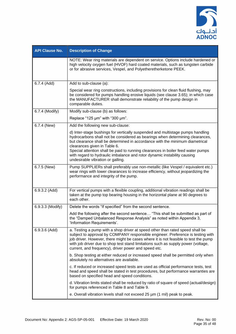
Document No: Appendix 2: AGS-SP-05-001 Effective Date: 19 March 2020 Rev. No: 00 Page 35 of 48
API Clause No. Description of Change
NOTE: Wear ring materials are dependent on service. Options include hardened or high velocity oxygen fuel (HVOF) hard coated materials, such as tungsten carbide or for abrasive services, Vespel, and Polyetheretherketone PEEK.
6.7.4 (Add) Add to sub-clause (a):
Special wear ring constructions, including provisions for clean fluid flushing, may be considered for pumps handling erosive liquids (see clause 3.65); in which case the MANUFACTURER shall demonstrate reliability of the pump design in comparable duties.
6.7.4 (Modify) Modify sub-clause (b) as follows:
Replace “125 µm” with “300 µm”.
6.7.4 (New) Add the following new sub-clause:
d) Inter-stage bushings for vertically suspended and multistage pumps handling hydrocarbons shall not be considered as bearings when determining clearances, but clearance shall be determined in accordance with the minimum diametrical clearances given in Table 6. Special attention shall be paid to running clearances in boiler feed water pumps with regard to hydraulic imbalance and rotor dynamic instability causing undesirable vibration or galling.
6.7.5 (New) Pump SUPPLIERs shall preferably use non-metallic (like Vespel / equivalent etc.) wear rings with lower clearances to increase efficiency, without jeopardizing the performance and integrity of the pump.
6.9.3.2 (Add) For vertical pumps with a flexible coupling, additional vibration readings shall be taken at the pump top bearing housing in the horizontal plane at 90 degrees to each other.
6.9.3.3 (Modify) Delete the words “If specified” from the second sentence.
Add the following after the second sentence… “This shall be submitted as part of the “Damped Unbalanced Response Analysis” as noted within Appendix 3, ‘Information Requirements’.
6.9.3.6 (Add) a. Testing a pump with a shop driver at speed other than rated speed shall be subject to approval by COMPANY responsible engineer. Preference is testing with job driver. However, there might be cases where it is not feasible to test the pump with job driver due to shop test stand limitations such as supply power (voltage, current, and frequency), driver power and speed etc.
b. Shop testing at either reduced or increased speed shall be permitted only when absolutely no alternatives are available.
c. If reduced or increased speed tests are used as official performance tests, test head and speed shall be stated in test procedures, but performance warranties are based on specified head and speed conditions.
d. Vibration limits stated shall be reduced by ratio of square of speed (actual/design) for pumps referenced in Table 8 and Table 9.
e. Overall vibration levels shall not exceed 25 µm (1 mil) peak to peak.

Document No: Appendix 2: AGS-SP-05-001 Effective Date: 19 March 2020 Rev. No: 00 Page 36 of 48
API Clause No. Description of Change
It is best to test a pump with its intended driver at rated speed. There might be occasions when this is not feasible. In those cases, COMPANY responsible engineer may approve test with a shop driver at a speed other than rated speed.
Table 8 - Vibration limits for overhung and between-bearings pumps
Add to Table 8 Discrete frequencies for pump shaft: for high energy pumps: f > n: Af < 0,33Au.
6.9.3.9 (New) Pumps furnished with proximity probes shall also be fitted with key phasor probes.
6.9.4.1 (Add) All rotor assemblies shall be dynamically balanced within the same limits. For pumps driven by HV and MV motors, rotating components shall be dynamically balanced in conformance to ISO 1940-1, grade G1. For pumps driven by LV motors, rotating components shall be dynamically balanced in conformance to ISO 1940-1, grade G2.5. Apply G2.5 to LV motors (definition of LV motors in electrical specifications).
6.9.4.4 (Modify) Modify first sentence to read… “Impellers, balancing drums, and similar rotating components shall be dynamically balanced in conformance to ISO 1940-1, grade G1.”
6.10.1.2 (Add) When hydrodynamic thrust bearings are proposed the following shall apply: a. Pump hydraulic design shall be such that the axial loads are unidirectional under all operating conditions. Thrust bearing shall be capable to stand transient thrust condition may also occur. b. SUPPLIER shall submit in his bid, curves showing the variation of axial load with capacity (zero flow to EOC flow) for design internal clearances and two times design internal clearances. For variable speed units, similar curve for maximum continuous speed and minimum speed shall be submitted.
6.12.1.8 (Modify) Replace this API/ISO clause with ….
“The MANUFACTURER, SUPPLIER and/or SUB-SUPPLIER shall furnish material certificates in accordance with BS EN ISO 10204 and ISO 10474, of the type indicated for each component in Table 6 – Material Certification for Centrifugal Pump Parts.
6.12.1.16 (New) A thermal stability test shall be performed on pump casings and shaft of austenitic stainless steel in accordance with the following:-
a. Thermal stability test shall hold the component at maximum operating temperature for 0.04 hour per mm (1 hour per in) of thickness.
b. Following the thermal stability test dimensional inspection reports shall be supplied to verify components are within SUPPLIER’s manufacturing tolerances.
6.12.2.3 (Add) Add the following at the end of sub-clause a):-
“The details of any proposed weld repair on wrought material or any major weld repair on cast material along with the relevant WPS (Welding Procedure Specification) and PQR (Procedure Qualification Record) shall be subject to prior approval by COMPANY. After weld repair, the material shall be heat-treated (if required) in accordance with the relevant material specification and/or fabrication standard. A major weld repair shall be followed by heat treatment in accordance with the relevant material specification and/or fabrication standard. Details of all
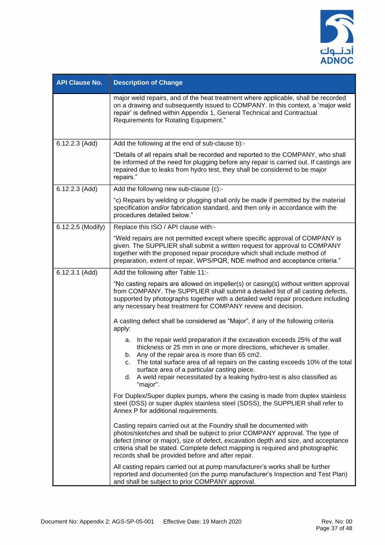
Document No: Appendix 2: AGS-SP-05-001 Effective Date: 19 March 2020 Rev. No: 00 Page 37 of 48
API Clause No. Description of Change
major weld repairs, and of the heat treatment where applicable, shall be recorded on a drawing and subsequently issued to COMPANY. In this context, a ‘major weld repair’ is defined within Appendix 1, General Technical and Contractual Requirements for Rotating Equipment.”
6.12.2.3 (Add) Add the following at the end of sub-clause b):-
“Details of all repairs shall be recorded and reported to the COMPANY, who shall be informed of the need for plugging before any repair is carried out. If castings are repaired due to leaks from hydro test, they shall be considered to be major repairs.”
6.12.2.3 (Add) Add the following new sub-clause (c):-
“c) Repairs by welding or plugging shall only be made if permitted by the material specification and/or fabrication standard, and then only in accordance with the procedures detailed below.”
6.12.2.5 (Modify) Replace this ISO / API clause with:-
“Weld repairs are not permitted except where specific approval of COMPANY is given. The SUPPLIER shall submit a written request for approval to COMPANY together with the proposed repair procedure which shall include method of preparation, extent of repair, WPS/PQR, NDE method and acceptance criteria.”
6.12.3.1 (Add) Add the following after Table 11:-
“No casting repairs are allowed on impeller(s) or casing(s) without written approval from COMPANY. The SUPPLIER shall submit a detailed list of all casting defects, supported by photographs together with a detailed weld repair procedure including any necessary heat treatment for COMPANY review and decision. A casting defect shall be considered as “Major”, if any of the following criteria apply:
a. In the repair weld preparation if the excavation exceeds 25% of the wall thickness or 25 mm in one or more directions, whichever is smaller.
b. Any of the repair area is more than 65 cm2. c. The total surface area of all repairs on the casting exceeds 10% of the total
surface area of a particular casting piece. d. A weld repair necessitated by a leaking hydro-test is also classified as
"major".
For Duplex/Super duplex pumps, where the casing is made from duplex stainless steel (DSS) or super duplex stainless steel (SDSS), the SUPPLIER shall refer to Annex P for additional requirements. Casting repairs carried out at the Foundry shall be documented with photos/sketches and shall be subject to prior COMPANY approval. The type of defect (minor or major), size of defect, excavation depth and size, and acceptance criteria shall be stated. Complete defect mapping is required and photographic records shall be provided before and after repair.
All casting repairs carried out at pump manufacturer’s works shall be further reported and documented (on the pump manufacturer’s Inspection and Test Plan) and shall be subject to prior COMPANY approval.
Document No: Appendix 2: AGS-SP-05-001 Effective Date: 19 March 2020 Rev. No: 00 Page 38 of 48
API Clause No. Description of Change
NOTE: Approval by COMPANY for any repairs shall not relieve the SUPPLIER of his responsibility to provide a product that is safe to operate, suitable for the original intended purpose that will comply in all respects with the Purchase order and attached datasheets/specifications.”
6.12.3.4 (Modify) Modify first sentence to read:-
“Connections welded to pressure casings shall be performed as specified in a) through to f) as follows.”
6.12.3.4 (Modify) Modify sub-clause b) to read:-
b) Auxiliary piping welding shall conform to the following requirements:
1. Auxiliary piping welded to alloy steel casings shall be of a material with the same nominal chemistry as casing material, except for 12 Cr materials.
2. Weld attaching 300 series stainless steel auxiliary pipe to 12 chrome casings shall be performed in conformance to the following steps: a) Oversize the socket weld connection and weld a “butter” layer with Inco
625 rod (minimum thickness 9,525 mm). b) PWHT the casting to a maximum hardness of 22HRC. c) Bore socket to the size for 300 series piping attachment. d) Attach the piping using ERNiCrMo-3 rod. e) No PWHT is required. If the piping requires being replaced during future
repairs, it can be removed and replaced without the need for further PWHT.
3. Carbon steel pipe shall be: a) Welded to 12 Cr casings with Inco “A” electrodes. b) Postweld heat treated to a maximum hardness of 22 HRC.
6.12.3.4 (Modify) Modify sub-clause d). Delete the words “If specified”
Modify sub-clause e). Replace last sentence and sub items (1) and (2) with: “Non-Destructive Examination of welds shall be performed in accordance with Table 7 – Inspection & NDT Minimum Requirements within QA Inspection and Testing Requirements – Appendix 2.”
6.12.3.5 (New) Welds for use in the following services and others as specified shall be stress relieved: a. MEA, DEA, MDEA, TEA, TEAL - Stock solutions b. MEA - Lean solution (CO2 only) c. MEA - Lean solution (CO2 and H2S) d. MEA, DEA, MDEA, TEA, TEAL - Rich solutions e. Hydrofluoric acid concentration greater than 96%.
6.12.4.5 (Add) Refer to ‘section 9.6.6 of this document.
6.13.2 (Add) Replace the first sentence with:-
“The nameplate shall be stamped with the following information. All text shall be in the English language and the numerical data shall be in SI units.”
Add the following new sub-clauses k) and l):-
k. Year of manufacture l. Purchaser’s order number
7.2.2 (Modify) Modify sub-clause (f) to read:- f) Couplings operating at speeds in excess of 3500 rpm and rated at over 746 kW
Document No: Appendix 2: AGS-SP-05-001 Effective Date: 19 March 2020 Rev. No: 00 Page 39 of 48
API Clause No. Description of Change
(1000 hp) shall conform to AGMA 9000, Class 9 standards for component balancing and assembly balance check.
Add new sub-clause (g):
g) Key, keyways and assembly/interference fits shall conform to AGMA9002 class.
7.3 The content of API 610 11th Edition, Section 7.3 ‘Baseplates’ shall apply in full.
7.3.12 (Add) Standard coating is inorganic zinc. This coating does not provide a bond strength that is as high as epoxy primers. Consider using epoxy primers instead of inorganic zinc.
7.3.15 (Add) Lifting lugs shall be attached using full penetration welds. As a minimum all lifting attachment welds shall be subject to 100% UT and 100% MT examination.
Lifting lugs shall be painted (or identified) in accordance with the relevant COMPANY business unit standard(s). In addition, lifting lugs shall be clearly marked with the Safe Working Load (SWL).
7.6 (Modify) Replace this ISO/API clause with…. “Refer to Appendix 1 – General Technical and Contractual Requirements for Rotating Equipment.”
8.1.7 (New) The SUPPLIER shall submit an Inspection and Test Plan (ITP) for approval by COMPANY prior to any pre-inspection meeting and prior to the start of manufacture. The SUPPLIER shall ensure that:-
a. The ITP meets the surveillance requirements determined by the criticality rating established by the criticality assessment and quality requirements.
b. The ITP includes all inspection and testing activities to be performed, including those at each SUB-SUPPLIER’s works and shall make reference to all testing procedures, control documents and resulting records and reports.
c. Each pump shall be tested in accordance with the approved ITP.
8.2.2.1 (Modify) Replace first sentence with:-
“Unless otherwise specified, pressure-casing materials shall be inspected in accordance with the requirements of Table 7 – Inspection & NDT Minimum Requirements within Section 11. The required inspections shall be included within the SUPPLIER’s Inspection and Test Plan (ITP) to be submitted to COMPANY.”
8.2.2.1.1 (New)
For double casing pumps, the outer casing pressure/temperature shall be used in deciding the inspection class. If the above indicates that Class I or II inspection is required, the inner casing shall be inspected to Class II.
8.2.2.1.2 (New)
For pressure casings manufactured from Corrosion Resistant Alloys (CRA materials) including but not limited to Duplex stainless steel, Super duplex or Inconel shall be subjected to inspection in accordance with INSPECTION CLASS I, as per Table 7 – Inspection & NDT Minimum Requirements regardless of the operating parameters.
Table 14 (Modify)
Delete “Table 14 — Pressure casing material inspection requirements” in its entirety. Replace with…. “Refer to Section 11, Table 7 – Inspection & NDT Minimum Requirements.”

Document No: Appendix 2: AGS-SP-05-001 Effective Date: 19 March 2020 Rev. No: 00 Page 40 of 48
API Clause No. Description of Change
8.2.2.1.3 (New)
When defects are found in castings which necessitate a major weld repair, the casting shall be inspected to the next more severe inspection class unless the initial inspection was already at Class I.
Minor weld repairs shall be inspected to the same inspection class as that for the initial inspection of the casting.
Major weld repairs shall be inspected to the next more severe inspection class than the initial inspection unless the initial inspection was already at Class I, in which case the weld repair shall be inspected at Class I.
8.2.2.2 (Modify) Replace the second sentence with:-
“The inner casing should be inspected to INSPECTION CLASS II.”
8.2.2.5.2 (New)
Areas of casting to be examined by radiography shall be subject to approval by COMPANY prior to examination. As a minimum, regions of abrupt section change, weld ends, chaplets, and areas adjacent to feeders and risers shall be included.
8.2.2.6 (Modify) Delete the words “If specified”.
8.2.2.7 (Modify) Delete the words “If specified” at the start of the first sentence.
Replace this API clause with…. “NDT acceptance criteria are to be applied in accordance with Table 5 – NDE Acceptance Criteria in Section 9.10 of “Appendix 2 – QA Inspection and Testing Requirements.”
8.2.2.8 (Modify) Replace the first and second sentences of this API clause with… “All alloy materials shall be subject to positive material identification (PMI) using recognized testing methods, instrumentation and standards. The SUPPLIER shall inform COMPANY of any proposed reduction in the extent of PMI, subject to COMPANY approval.”
8.2.2.9 (New) NDT of the equipment components and welds shall be carried out in accordance with Section 9.7 of “Appendix 2 – QA Inspection and Testing Requirements.”
8.3 Testing
8.3.1.1 Delete the words “If specified”.
8.3.1.4 (New) The type and number of tests in which the CONTRACTOR will participate shall be confirmed prior to manufacture. The CONTRACTOR should normally participate in the following tests (see Minimum Quality Summary Sheet and the data/requisition sheets for extent of participation):
a. Hydrostatic test in accordance with Paragraph 8.3.2
b. Performance test in accordance with Paragraph 8.3.3 including disassembly and inspection per Paragraph 8.3.3.7.
c. MRT in accordance with clause 8.3.4.2.
d. NPSHR test in accordance with Paragraph 8.3.4.3 when any of the following conditions exist OR if it has been specified that such a test is required.
i. Pump capacity is less than 1500 m3/h and the difference between NPSHA and NPSHR (anticipated and actual) is less than 2 m.
ii. Pump capacity is 1500 m3/h or more and the difference between NPSHA and NPSHR (anticipated and actual) is less than 3 m.
Document No: Appendix 2: AGS-SP-05-001 Effective Date: 19 March 2020 Rev. No: 00 Page 41 of 48
API Clause No. Description of Change
e. Complete unit test in accordance with Paragraph 8.3.4.4.1 is required for pumps driven by electric motors with variable speed drive system control or when the discharge pressure exceeds 100 kg/cm2g or when driver rating exceeds 1500 kW or if it has been specified that such a test is required.
f. Complete unit test in accordance with Paragraph 8.3.4.4.1 is required for pumps driven by electric motors with variable speed drive system control or when the discharge pressure exceeds 100 kg/cm2g or when driver rating exceeds 1500 kW or if it has been specified that such a test is required.
An NPSH test shall be performed where specified on the equipment datasheets or where the margin between NPSHR and NPSHA dictates that an NPSH test is required. Refer to ‘Process Design Criteria’, AGES-SP-026 for required NPSH margins.
8.3.1.5 (New) Immediately following both hydrostatic and performance testing, pump wetted parts shall be drained and dried to avoid corrosion or concentration of chlorides.
8.3.2.2 (Add) All pump pressure casing components shall be tested to the same pressure.
8.3.2.4 (Add) For cast pressure containing components, the hydrostatic test duration shall be a minimum of 30 minutes or time taken to complete witness by appropriate method whichever is more.
8.3.2.5 (Add) Water used for the hydrostatic test shall not contain chlorides of more than 50 ppm.
8.3.2.7 (Add) Add sub clause e)…. “The wetting agent to be used shall be subject to the approval of the COMPANY.”
8.3.2.8 (Modify) Replace the second sentence in this ISO/API clause with:
“The chloride content of test liquids shall be as specified within section 12.3 of this document (Appendix 2).”
8.3.2.11 (Add) Pressure castings shall be hydro tested for duration not less than 30 minutes minimum or to complete the inspection of the tested parts.
8.3.2.12 (Add)
[PSR]
"Replace the API clause with ….. “All pump pressure-casing components SHALL [PSR] be tested to the same pressure."
8.3.2.15 (Modify) Replace this ISO/API clause with…. “Cooling passages and components, including jackets for bearings, seal chambers, oil coolers and seal coolers, shall be tested at 1.5 times the cooling water design pressure."
8.3.2.16 (Add) Cooling water piping shall pass a leak test for 30 minutes. No leaks or seepage will be accepted.
8.3.2.17 (New) Parts shall not be coated or painted until after successful hydrotesting. Any repairs to the pressure casing components shall require a repeat of the hydrostatic test.
8.3.3.2 (Modify) Modify sub-clause d) to read… "If unacceptable seal leakage during test is detected, this shall require the assembled pump and seal to be rerun to demonstrate satisfactory seal performance."
8.3.3.2 (Modify) Add to sub-clause e)… “If equipment has constant level oilers, the job oilers shall be used during operation testing."
8.3.3.2 (Add) Add to sub-clause f)… “1) Dynamic testing of pumps specified for pure oil mist lubrication shall be performed using ‘contract’ oil mist generator and supply
Document No: Appendix 2: AGS-SP-05-001 Effective Date: 19 March 2020 Rev. No: 00 Page 42 of 48
API Clause No. Description of Change
system. Use of oil ring lubrication or purchased oil mist system for testing shall be subject to COMPANY approval.
Use of ring oil lubrication does not mimic field installation and does not prove the mechanical integrity of the pump. Take care accepting testing on oil mist equipment without oil mist.
2) Pumps fitted for oil mist lubrication that will be tested using oil ring lubrication shall have oil rings removed prior to shipment.
3) System supplying oil mist to test pump bearings shall be in operation for at least 30 min prior to dynamic testing."
8.3.3.2 (Add) Add to sub-clause f)… “Where pressure lubricating systems are used, the lubricating oil temperature shall be held for at least 1 hours at the value corresponding to the maximum allowable viscosity, and for minimum 3 hours at the value corresponding to the minimum allowable viscosity (highest supply temp. conditions). At minimum and maximum viscosity, and at the viscosity corresponding to the normal operating oil temperature, shaft vibration shall be measured and vibration frequency analyzed to check for instabilities.”
8.3.3.2 (Add) Add new sub-clause j):-
"j) For pumps in vital or non-spared essential services, when specified, pumps shall be tested with contract lube oil systems.
8.3.3.2 (Add) Add new sub-clause k):-
“k) Contract driver shall be used for shop performance test when it is available at time of test, unless otherwise agreed with COMPANY."
8.3.3.3 (Modify) First sentence to read "Unless otherwise specified, the performance test shall be conducted as specified in a) through g) and in accordance with Section 12.5 of this Appendix.”
Add to sub clause a):-
“Stuffing box pressure shall be recorded during performance and NPSH tests for pumps operating with fluids that have a specific gravity of 0.6 or less. Vertically suspended submerged pumps (turbine type) shall be tested at minimum submergence of the pump. All conditions shall be stable at each test point.”
Add to sub clause c):-
“Variable speed pumps shall be tested additionally at maximum continuous speed and at minimum allowable speed.”
Modify sub clause e). Delete the words "If specified".
Add new sub-clause f) and g) as follows:-
f) When conducting a performance test on pumps that will be installed with a minimum flow or automatic recirculation valve, the SUPPLIER shall provide a means to determine the onset of recirculation at or near the minimum continuous stable flow. The details of the test procedure and method used to determine this value shall be mutually agreed between SUPPLIER and COMPANY to ensure that there is no risk of damage to the pump. The test procedure(s) shall be formalized during the Pre-Inspection Meeting (PIM).
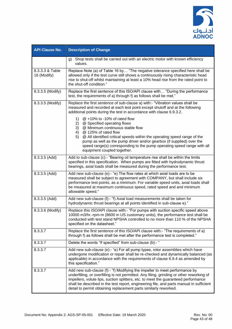
Document No: Appendix 2: AGS-SP-05-001 Effective Date: 19 March 2020 Rev. No: 00 Page 43 of 48
API Clause No. Description of Change
g) Shop tests shall be carried out with an electric motor with known efficiency values.
8.3.3.3 & Table 16 (Modify)
Replace Note (a) of Table 16 by… “The negative tolerance specified here shall be allowed only if the test curve still shows a continuously rising characteristic head rise to shut-off whilst maintaining at least a 10% head rise from the rated point to the shut-off condition."
8.3.3.5 (Modify) Replace the first sentence of this ISO/API clause with… “During the performance test, the requirements of a) through f) as follows shall be met.”
8.3.3.5 (Modify) Replace the first sentence of sub-clause a) with:- “Vibration values shall be measured and recorded at each test point except shutoff and at the following additional points during the test in accordance with clause 6.9.3.2.
1) @ +10% to -10% of rated flow 2) @ Specified operating flows 3) @ Minimum continuous stable flow 4) @ 125% of rated flow 5) @ All identified critical speeds within the operating speed range of the
pump as well as the pump driver and/or gearbox (if supplied) over the speed range(s) corresponding to the pump operating speed range with all equipment coupled together.
8.3.3.5 (Add) Add to sub-clause (c):- “Bearing oil temperature rise shall be within the limits specified in this specification. When pumps are fitted with hydrodynamic thrust bearings, axial loads shall be measured during the performance test.
8.3.3.5 (Add) Add new sub-clause (e):- “e) The flow rates at which axial loads are to be measured shall be subject to agreement with COMPANY, but shall include six performance test points, as a minimum. For variable speed units, axial loads shall be measured at maximum continuous speed, rated speed and and minimum allowable speed."
8.3.3.5 (Add) Add new sub-clause (f):- “f) Axial load measurements shall be taken for hydrodynamic thrust bearings at all points identified in sub-clause e).”
8.3.3.6 (Modify) Replace this ISO/API clause with:- “For pumps with suction specific speed above 10000 m3/hr.-rpm-m (8600 in US customary units), the performance test shall be conducted with test stand NPSHA controlled to no more than 110 % of the NPSHA specified on the datasheet.”
8.3.3.7 Replace the first sentence of this ISO/API clause with:- “The requirements of a) through f) as follows shall be met after the performance test is completed.”
8.3.3.7 Delete the words “If specified” from sub-clause (b):- “
8.3.3.7 Add new sub-clause (e):- “e) For all pump types, rotor assemblies which have undergone modification or repair shall be re-checked and dynamically balanced (as applicable) in accordance with the requirements of clause 6.9.4 as amended by this specification.”
8.3.3.7
Add new sub-clause (f):- “f) Modifying the impeller to meet performance by underfilling, or overfilling is not permitted. Any filing, grinding or other reworking of impellers, volute lips, suction splitters, etc. to meet the guaranteed performance shall be described in the test report, engineering file, and parts manual in sufficient detail to permit obtaining replacement parts similarly reworked.
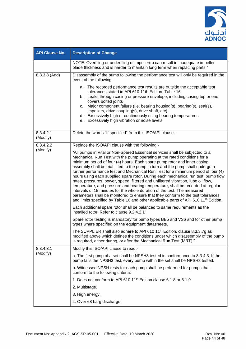
Document No: Appendix 2: AGS-SP-05-001 Effective Date: 19 March 2020 Rev. No: 00 Page 44 of 48
API Clause No. Description of Change
NOTE: Overfiling or underfiling of impeller(s) can result in inadequate impeller blade thickness and is harder to maintain long term when replacing parts.”
8.3.3.8 (Add) Disassembly of the pump following the performance test will only be required in the event of the following:-
a. The recorded performance test results are outside the acceptable test tolerances stated in API 610 11th Edition, Table 16.
b. Leaks through casing or pressure envelope, including casing top or end covers bolted joints
c. Major component failure (i.e. bearing housing(s), bearing(s), seal(s), impellers, drive coupling(s), drive shaft, etc)
d. Excessively high or continuously rising bearing temperatures e. Excessively high vibration or noise levels
8.3.4.2.1 (Modify)
Delete the words "If specified" from this ISO/API clause.
8.3.4.2.2 (Modify)
Replace the ISO/API clause with the following:-
“All pumps in Vital or Non-Spared Essential services shall be subjected to a Mechanical Run Test with the pump operating at the rated conditions for a minimum period of four (4) hours. Each spare pump rotor and inner casing assembly shall be trial fitted to the pump in turn and the pump shall undergo a further performance test and Mechanical Run Test for a minimum period of four (4) hours using each supplied spare rotor. During each mechanical run test, pump flow rates, pressures, power, speed, filtered and unfiltered vibration, lube oil flow, temperature, and pressure and bearing temperature, shall be recorded at regular intervals of 15 minutes for the whole duration of the test. The measured parameters shall be monitored to ensure that they conform to the test tolerances and limits specified by Table 16 and other applicable parts of API 610 11th Edition.
Each additional spare rotor shall be balanced to same requirements as the installed rotor. Refer to clause 9.2.4.2.1"
Spare rotor testing is mandatory for pump types BB5 and VS6 and for other pump types where specified on the equipment datasheets.
The SUPPLIER shall also adhere to API 610 11th Edition, clause 8.3.3.7g as modified above which defines the conditions under which disassembly of the pump is required, either during, or after the Mechanical Run Test (MRT).”
8.3.4.3.1 (Modify)
Modify this ISO/API clause to read:-
a. The first pump of a set shall be NPSH3 tested in conformance to 8.3.4.3. If the pump fails the NPSH3 test, every pump within the set shall be NPSH3 tested.
b. Witnessed NPSH tests for each pump shall be performed for pumps that conform to the following criteria:
1. Does not conform to API 610 11th Edition clause 6.1.8 or 6.1.9.
2. Multistage.
3. High energy.
4. Over 68 barg discharge.

Document No: Appendix 2: AGS-SP-05-001 Effective Date: 19 March 2020 Rev. No: 00 Page 45 of 48
API Clause No. Description of Change
5. Process fluid over 343°C.
6. Multiple applications.
c. During testing, guards shall be installed for personnel protection.
d. NPSH3 shall be determined at each test point, except shutoff. See 8.3.3.3.a).
Knee curves provide a graphical representation of the pump head during the NPSH testing, which documents the impeller characteristics and confirms the 3% head drop point.
NPSH3 test with suction valve throttling is not acceptable unless pump capacity exceeds shop test capability for suppression test."
8.3.4.3.2 (Add) The NPSH3 shall always assume that the pump is handling water. No corrections shall be made for other liquids. NPSH3 test shall be performed by vacuum suppression method, not suction valve throttling method, except where approved by COMPANY.
Cavitation tests on “pump models” are only permitted subject to COMPANY approval.
Testing with only the first stage installed or by using model pumps shall be subject to the approval of the COMPANY.
8.3.4.4.1 (Modify)
Replace the first sentence of this ISO/API clause with:-
“A complete unit test (string test) is required:-
1) when specified in the equipment datasheets or 2) when the discharge pressure exceeds 100 barg or 3) when the driver rating exceeds 1500 kW.
If a complete unit test is specified, only the motor driven unit shall be subject to the complete unit test requirement. Motor driven pump complete unit tests shall be performed with the job lube oil system, job seals and seal system.
Unless otherwise specified, a complete unit test for first unit (for identical pumps) shall be performed and, if successful, then driver and pump (shaft line) only to be tested for the other identical units.
If first unit complete unit test was not satisfactory (i.e. fails in terms of operating and mechanical performance) then all units shall undergo a complete unit test. This test is in addition to the individual equipment or component test.”
8.3.4.5 (Modify) Replace this ISO/API clause with:-
“A noise test shall be carried out in accordance with Section 12.8 of this Appendix.”
8.3.4.6 (Modify) Replace the second sentence of this ISO/API clause with:-
“The SUPPLIER shall submit detailed test procedures for all auxiliary equipment items which shall be submitted to COMPANY/CONTRACTOR for review at least four weeks prior to each individual test. Refer to ‘Appendix 3 – Information Requirements’ for minimum required content of submitted test procedures.
8.3.4.7 (Add) A bearing housing resonance test shall be carried out for all high energy pumps and for single stage overhung pumps with driver ratings of 150 kW (200 hp) or greater.
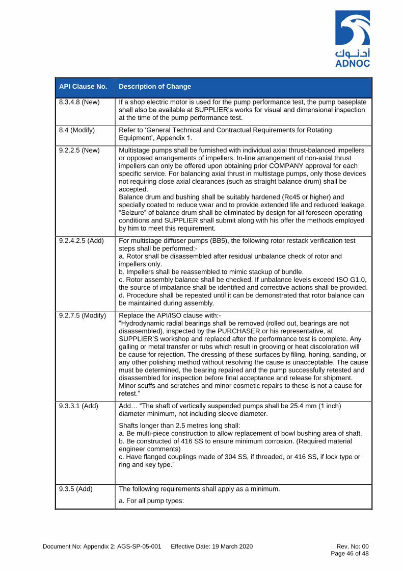
Document No: Appendix 2: AGS-SP-05-001 Effective Date: 19 March 2020 Rev. No: 00 Page 46 of 48
API Clause No. Description of Change
8.3.4.8 (New) If a shop electric motor is used for the pump performance test, the pump baseplate shall also be available at SUPPLIER’s works for visual and dimensional inspection at the time of the pump performance test.
8.4 (Modify) Refer to ‘General Technical and Contractual Requirements for Rotating Equipment’, Appendix 1.
9.2.2.5 (New) Multistage pumps shall be furnished with individual axial thrust-balanced impellers or opposed arrangements of impellers. In-line arrangement of non-axial thrust impellers can only be offered upon obtaining prior COMPANY approval for each specific service. For balancing axial thrust in multistage pumps, only those devices not requiring close axial clearances (such as straight balance drum) shall be accepted. Balance drum and bushing shall be suitably hardened (Rc45 or higher) and specially coated to reduce wear and to provide extended life and reduced leakage. “Seizure” of balance drum shall be eliminated by design for all foreseen operating conditions and SUPPLIER shall submit along with his offer the methods employed by him to meet this requirement.
9.2.4.2.5 (Add) For multistage diffuser pumps (BB5), the following rotor restack verification test steps shall be performed:- a. Rotor shall be disassembled after residual unbalance check of rotor and impellers only. b. Impellers shall be reassembled to mimic stackup of bundle. c. Rotor assembly balance shall be checked. If unbalance levels exceed ISO G1.0, the source of imbalance shall be identified and corrective actions shall be provided. d. Procedure shall be repeated until it can be demonstrated that rotor balance can be maintained during assembly.
9.2.7.5 (Modify) Replace the API/ISO clause with:- “Hydrodynamic radial bearings shall be removed (rolled out, bearings are not disassembled), inspected by the PURCHASER or his representative, at SUPPLIER’S workshop and replaced after the performance test is complete. Any galling or metal transfer or rubs which result in grooving or heat discoloration will be cause for rejection. The dressing of these surfaces by filing, honing, sanding, or any other polishing method without resolving the cause is unacceptable. The cause must be determined, the bearing repaired and the pump successfully retested and disassembled for inspection before final acceptance and release for shipment. Minor scuffs and scratches and minor cosmetic repairs to these is not a cause for retest.”
9.3.3.1 (Add) Add… “The shaft of vertically suspended pumps shall be 25.4 mm (1 inch) diameter minimum, not including sleeve diameter.
Shafts longer than 2.5 metres long shall: a. Be multi-piece construction to allow replacement of bowl bushing area of shaft. b. Be constructed of 416 SS to ensure minimum corrosion. (Required material engineer comments) c. Have flanged couplings made of 304 SS, if threaded, or 416 SS, if lock type or ring and key type.”
9.3.5 (Add) The following requirements shall apply as a minimum.
a. For all pump types:

Document No: Appendix 2: AGS-SP-05-001 Effective Date: 19 March 2020 Rev. No: 00 Page 47 of 48
API Clause No. Description of Change
1. If component balancing is required or specified, rigid adjustable spacer coupling shall also be component balanced. 2. Vertical turbine pumps rated at 3000 rpm or higher shall be component balanced. b. For vertical suspended pumps, a critical speed analysis shall be performed of the basic structural elements to avoid a design that would result in excitation of natural frequencies, unless records are provided for another pump that meets the following requirements: 1. Identical rotor geometry as proposed pump. 2. Identical bearing configuration as proposed pump. 3. Field operation conforms to requirements of proposed pump.
9.3.8.2.4 (New) Line couplings of vertically suspended pumps shall be rigid and shall be designed for accurate alignment during assembly and operation. Muff couplings are not acceptable.
9.3.8.3.3 (Modify)
Delete the words “If specified” at the beginning of the sentence.

THE CONTENTS OF THIS DOCUMENT ARE PROPRIETARY.
INFORMATION REQUIREMENTS
FOR
CENTRIFUGAL PUMPS (API 610)
SPECIFICATION
Appendix 3 - AGES-SP-05-001

Appendix 3: AGS-SP-05-001Information Requirements Effective Date: 19 March 2020
Rev 00Page 2 of 21
Information Requirements
for
Centrifugal Pumps
Insert Project Logo Here
CLIENT : Insert Client_name
PROJECT TITLE : Insert Project Title
PROJECT LOCATION : Insert Project_location
JOB/PROJECT NUMBER : Insert Job/Project number here
TAG No. : Insert Tag_No
SERVICE : Insert Service Description
DOCUMENT NUMBER : Insert Project Document Number
REVISION : Insert Project Document Revision
Issue Date Description of Change By Checked Approved
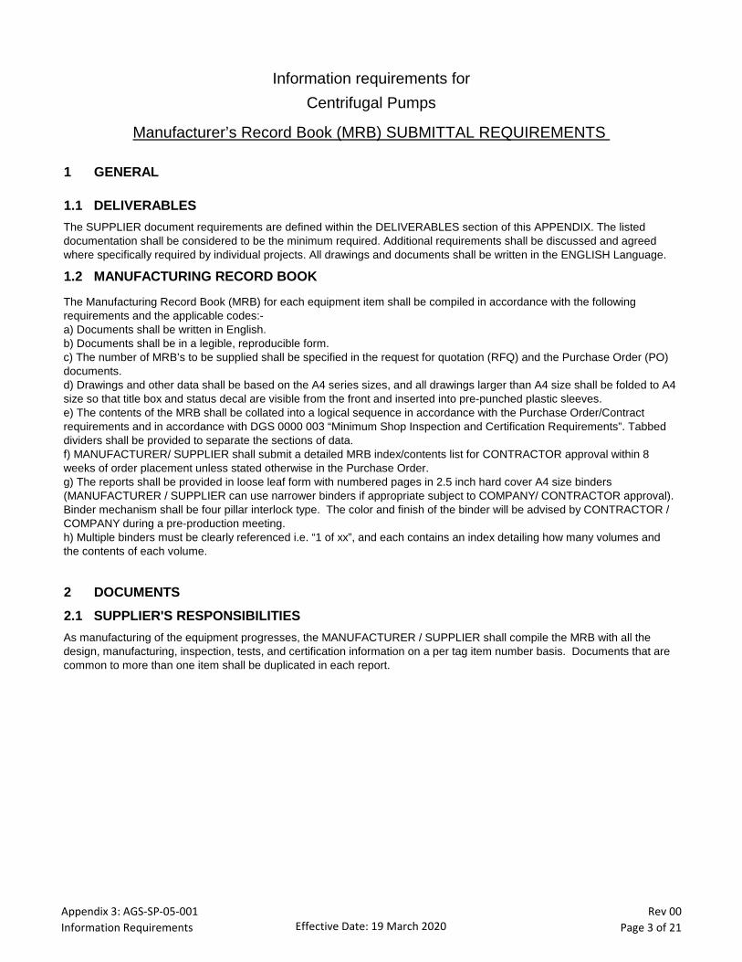
Appendix 3: AGS-SP-05-001Information Requirements Effective Date: 19 March 2020
Rev 00Page 3 of 21
Information requirements for
Centrifugal Pumps
Manufacturer’s Record Book (MRB) SUBMITTAL REQUIREMENTS
1 GENERAL
1.1 DELIVERABLES
The SUPPLIER document requirements are defined within the DELIVERABLES section of this APPENDIX. The listed
documentation shall be considered to be the minimum required. Additional requirements shall be discussed and agreed
where specifically required by individual projects. All drawings and documents shall be written in the ENGLISH Language.
1.2 MANUFACTURING RECORD BOOK
The Manufacturing Record Book (MRB) for each equipment item shall be compiled in accordance with the following
requirements and the applicable codes:-
a) Documents shall be written in English.
b) Documents shall be in a legible, reproducible form.
c) The number of MRB’s to be supplied shall be specified in the request for quotation (RFQ) and the Purchase Order (PO)
documents.
d) Drawings and other data shall be based on the A4 series sizes, and all drawings larger than A4 size shall be folded to A4
size so that title box and status decal are visible from the front and inserted into pre-punched plastic sleeves.
e) The contents of the MRB shall be collated into a logical sequence in accordance with the Purchase Order/Contract
requirements and in accordance with DGS 0000 003 “Minimum Shop Inspection and Certification Requirements”. Tabbed
dividers shall be provided to separate the sections of data.
f) MANUFACTURER/ SUPPLIER shall submit a detailed MRB index/contents list for CONTRACTOR approval within 8
weeks of order placement unless stated otherwise in the Purchase Order.
g) The reports shall be provided in loose leaf form with numbered pages in 2.5 inch hard cover A4 size binders
(MANUFACTURER / SUPPLIER can use narrower binders if appropriate subject to COMPANY/ CONTRACTOR approval).
Binder mechanism shall be four pillar interlock type. The color and finish of the binder will be advised by CONTRACTOR /
COMPANY during a pre-production meeting.
h) Multiple binders must be clearly referenced i.e. “1 of xx”, and each contains an index detailing how many volumes and
the contents of each volume.
2 DOCUMENTS
2.1 SUPPLIER'S RESPONSIBILITIES
As manufacturing of the equipment progresses, the MANUFACTURER / SUPPLIER shall compile the MRB with all the
design, manufacturing, inspection, tests, and certification information on a per tag item number basis. Documents that are
common to more than one item shall be duplicated in each report.
Appendix 3: AGS-SP-05-001Information Requirements Effective Date: 19 March 2020
Rev 00Page 4 of 21
2.1 SUPPLIER'S RESPONSIBILITIES (Continued)
The MANUFACTURER / SUPPLIER shall present MRB’s to the nominated inspector at each inspection visit. It is also their
responsibility to ensure that Inspection & Test Plans are signed and dated by the nominated inspector on the day of any
Inspection / Test. The spine and cover of each binder shall indicate the following as a minimum:-
a) Manufacturing Data Report
b) Project Name
c) MANUFACTURER / SUPPLIER Name
d) Purchase Order No.
e) Equipment No.
f) Equipment Description
g) MANUFACTURER / SUPPLIER Order Ref. No.
h) MANUFACTURER / SUPPLIER Doc. No.
i) Date of Issue and Revision
j) Alterations, deletions, or additions to certification are not normally permitted, and a new document must be prepared.
However where this is not possible the alteration must be approved, signed and dated. Additions and revisions shall be
added to the documentation, not as a replacement but as an addition to the existing records
k) The Manufacturing Data Report shall, after being accepted by clear endorsement of each page by stamp, date and
signature of the nominated inspector, be submitted to the CONTRACTOR.
l) MDR documents that are already approved by CONTRACTOR with a signed and dated endorsement do not require
additional endorsement by the nominated inspector at the MANUFACTURER / SUPPLIER works. The nominated inspector
shall endorse the index as correct with reference to documents embodied within the MRB. For multi-page documents the
first page (used for approval) shall clearly state the document total number of pages and each page shall be numbered.
CONTRACTOR can use dated stamps, subject to COMPANY approval (without requirement for signature endorsement)
providing stamp is uniquely identifiable to individual inspectors.
m) The original and the required number of copies shall be forwarded promptly after the completion of the equipment in
accordance with the terms and conditions of the purchase order. If the order is subject to inspection by COMPANY /
CONTRACTOR, the release note for the acceptance of the equipment shall only be issued when the manufacturing report,
including the required number of copies, is presented.
n) The use of colored markers to highlight certificates shall not be permitted.
o) The use of correction fluids is not permitted.
p) When test / material certification is called for, these certificates are to be countersigned by COMPANY / CONTRACTOR.
3 MANUFACTURER/ SUPPLIER QC DOCUMENTATION AND CERTIFICATION
Supplier document and deliverables shall be as per the attached schedule of DELIVERABLES, which shall be updated with
required document submission times according to the project schedule requirements.
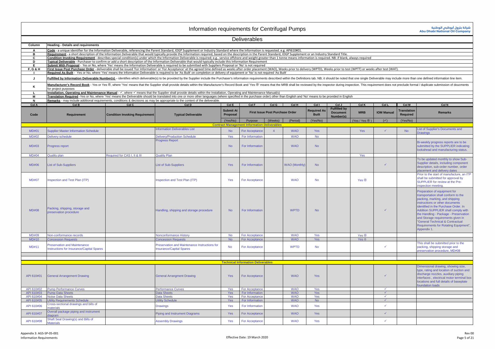
Appendix 3: AGS-SP-05-001Information Requirements Effective Date: 19 March 2020
Rev 00Page 5 of 21
Column
A
B
C
D
E
F, G & H
I
J
K
L
M
N
Col A Col B Col C Col D Col E Col F Col G Col H Col I Col J Col K Col L Col M Col N
Submit At
Proposal
Required As
Built
Fulfilled by
Document
Number(s)
MRB IOM ManualTranslation
RequiredRemarks
(Yes/No) Purpose (Weeks) (Period) (Yes/No) (Yes / Yes ® ) () (Yes/No)
MD#01 Supplier Master Information ScheduleInformation Deliverables List
No For Acceptance 4 WAO Yes Yes No List of Supplier's Documents and
Drawings
MD#02 Delivery schedule Delivery/Production Schedule Yes For Information WAO No
MD#03 Progress report
Progress Report
No For Information WAO No
Bi-weekly progress reports are to be
submitted by the SUPPLIER indicating
lookahead and manufacturing status.
MD#04 Quality plan Required for CAS I, II & III Quality Plan Yes
MD#06 List of Sub-Suppliers List of Sub-Suppliers Yes For Information WAO (Monthly) No
To be updated monthly to show Sub-
Supplier details, including component
description, sub-order number, order
placement and delivery dates
MD#07 Inspection and Test Plan (ITP) Inspection and Test Plan (ITP) Yes For Acceptance WAO No Yes ®
Prior to the start of manufacture, an ITP
shall be submitted for approval by
SUPPLIER for review at the Pre-
inspection meeting.
MD#08Packing, shipping, storage and
preservation procedureHandling, shipping and storage procedure No For Information WPTD No
Preparation of equipment for
transportation shall conform to the
packing, marking, and shipping
instructions or other documents
identified in the Purchase Order. In
Addition SUPPLIER shall comply with
the Handling - Package - Preservation
and Storage requirements given in
"General Technical & Contractual
Requirements for Rotating Equipment",
Appendix 1.
MD#09 Non-conformance records Nonconformance History No For Acceptance WAO Yes Yes ®MD#10 Concession Requests Concession Requests No For Acceptance WAO Yes Yes ®
MD#11Preservation and Maintenance
Instructions for Insurance/Capital Spares
Preservation and Maintenance Instructions for
Insurance/Capital SparesNo For Acceptance WPTD No
This shall be submitted prior to the
packing, shipping storage and
preservation procedure, MD#08
API 610#01 General Arrangement Drawing General Arrangment Drawing Yes For Acceptance WAO Yes
Dimensional drawing, showing size,
type, rating and location of suction and
discharge nozzles, auxiliary piping
interfaces , electrical motor terminal box
locations and full details of baseplate
foundation loads
API 610#02 Pump Performance Curves Performance Curves Yes For Acceptance WAO Yes API 610#03 Pump Data Sheets Data Sheets Yes For Information WAO Yes API 610#04 Noise Data Sheets Data Sheets Yes For Acceptance WAO Yes API 610#05 Utility Requirements Schedule Utility Schedule Yes For Information WAO No
API 610#06Cross-sectional drawings and bills of
materialsDrawings Yes For Information WAO Yes
API 610#07Overall package piping and instrument
diagramPiping and Instrument Diagrams Yes For Acceptance WAO Yes
API 610#08Shaft Seal Drawing(s) and Bills of
MaterialsAssembly Drawings Yes For Acceptance WAO Yes
Translation Required -Yes or No, where 'Yes' means the Deliverable should be translated into one or more other languages (where specified in the purchase order) other than English and 'No' means to be provided in English
Information requirements for Centrifugal Pumps
DeliverablesHeading - Details and requirements
Code - a unique identifier for the Information Deliverable, referencing the Parent Standard, IOGP Supplement or Industry Standard where the Information is requested. e.g. API610#01.Requirement - a short description of the Information Deliverable that would typically provide the Information required, based on the description in the Parent Standard, IOGP Supplement or an Industry Standard Title.Condition Invoking Requirement - describes special condition(s) under which the Information Deliverable is required; e.g.. service offshore and weight greater than 1 tonne means information is required. NB: if blank, always requiredTypical Deliverable - Purchaser to confirm or add a short description of the Information Deliverable that would typically include this Information RequirementSubmit With Proposal - Yes or No, where ‘Yes' means the Information Deliverable is required to be submitted with Suppliers Proposal or 'No' is not requiredFirst Issue Post Purchase Order - deliverable shall be issued 'For Information' or 'For Acceptance' at the agreed time defined as weeks after order placement (WAO), Weeks prior to delivery (WPTD), Weeks prior to test (WPTT) or weeks after test (WAT).Required As Built - Yes or No, where ‘Yes' means the Information Deliverable is required to be 'As Built' on completion or delivery of equipment or 'No' is not required 'As Built'
Fulfilled by Information Deliverable Number(s) – identifies which deliverable(s) to be provided by the Supplier include the Purchaser's information requirements described within the Definitions tab. NB; it should be noted that one single Deliverable may include more than one defined information line item.
Manufacturer's Record Book - Yes or Yes ®, where 'Yes' means that the Supplier shall provide details within the Manufacturer's Record Book and 'Yes ®' means that the MRB shall be reviewed by the inspector during inspection. This requirement does not preclude formal / duplicate submission of doucments
for project purposes
Installation, Operating and Maintenance Manual - , where means that the Supplier shall provide details within the Installation, Operating and Maintenance Manual(s)
Contract Management Information Deliverables
Technical Information Deliverables
Remarks - may include additional requirements, conditions & decisions as may be appropriate to the content of the deliverable.
Code Requirement Condition Invoking Requirement Typical DeliverableFirst Issue Post Purchase Order
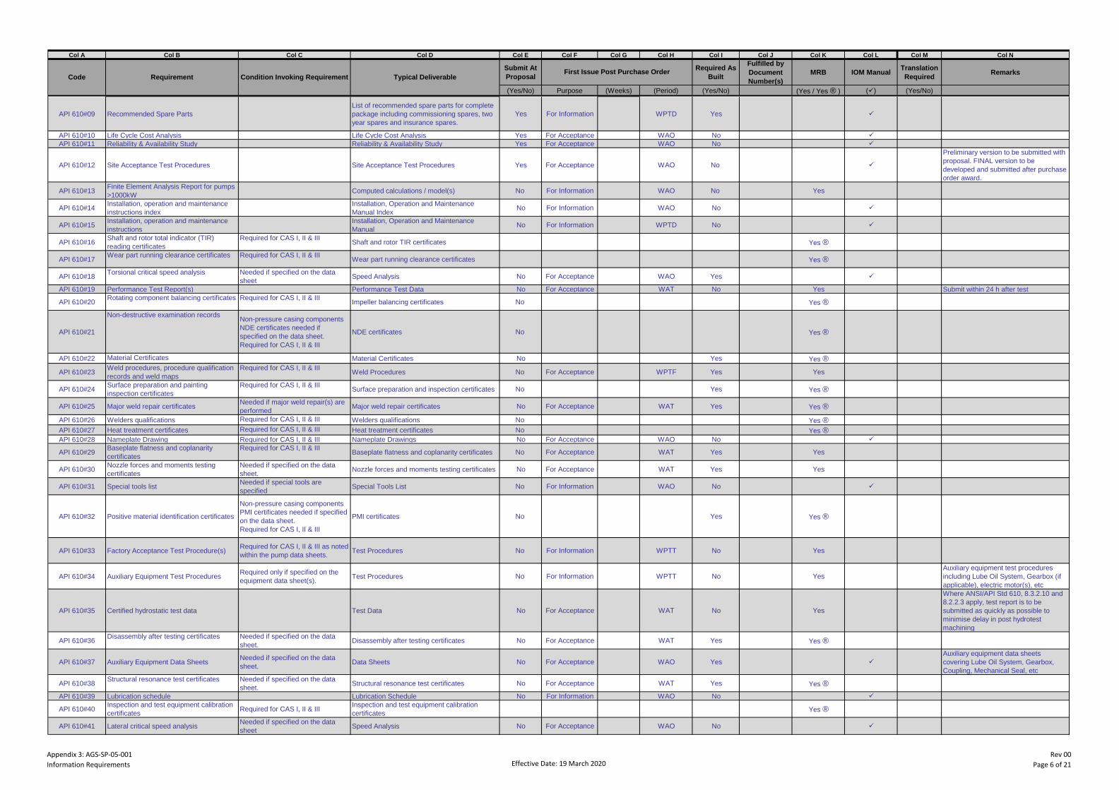
Appendix 3: AGS-SP-05-001Information Requirements Effective Date: 19 March 2020
Rev 00Page 6 of 21
Col A Col B Col C Col D Col E Col F Col G Col H Col I Col J Col K Col L Col M Col N
Submit At
Proposal
Required As
Built
Fulfilled by
Document
Number(s)
MRB IOM ManualTranslation
RequiredRemarks
(Yes/No) Purpose (Weeks) (Period) (Yes/No) (Yes / Yes ® ) () (Yes/No)
Code Requirement Condition Invoking Requirement Typical DeliverableFirst Issue Post Purchase Order
API 610#09 Recommended Spare Parts
List of recommended spare parts for complete
package including commissioning spares, two
year spares and insurance spares.
Yes For Information WPTD Yes
API 610#10 Life Cycle Cost Analysis Life Cycle Cost Analysis Yes For Acceptance WAO No API 610#11 Reliability & Availability Study Reliability & Availability Study Yes For Acceptance WAO No
API 610#12 Site Acceptance Test Procedures Site Acceptance Test Procedures Yes For Acceptance WAO No
Preliminary version to be submitted with
proposal. FINAL version to be
developed and submitted after purchase
order award.
API 610#13Finite Element Analysis Report for pumps
>1000kWComputed calculations / model(s) No For Information WAO No Yes
API 610#14Installation, operation and maintenance
instructions index
Installation, Operation and Maintenance
Manual IndexNo For Information WAO No
API 610#15Installation, operation and maintenance
instructions
Installation, Operation and Maintenance
ManualNo For Information WPTD No
API 610#16Shaft and rotor total indicator (TIR)
reading certificates
Required for CAS I, II & IIIShaft and rotor TIR certificates Yes ®
API 610#17Wear part running clearance certificates Required for CAS I, II & III
Wear part running clearance certificates Yes ®
API 610#18Torsional critical speed analysis Needed if specified on the data
sheetSpeed Analysis No For Acceptance WAO Yes
API 610#19 Performance Test Report(s) Performance Test Data No For Acceptance WAT No Yes Submit within 24 h after test
API 610#20Rotating component balancing certificates Required for CAS I, II & III
Impeller balancing certificates No Yes ®
API 610#21
Non-destructive examination recordsNon-pressure casing components
NDE certificates needed if
specified on the data sheet.
Required for CAS I, II & III
NDE certificates No Yes ®
API 610#22 Material Certificates Material Certificates No Yes Yes ®
API 610#23Weld procedures, procedure qualification
records and weld maps
Required for CAS I, II & IIIWeld Procedures No For Acceptance WPTF Yes Yes
API 610#24Surface preparation and painting
inspection certificates
Required for CAS I, II & IIISurface preparation and inspection certificates No Yes Yes ®
API 610#25 Major weld repair certificatesNeeded if major weld repair(s) are
performedMajor weld repair certificates No For Acceptance WAT Yes Yes ®
API 610#26 Welders qualifications Required for CAS I, II & III Welders qualifications No Yes ®API 610#27 Heat treatment certificates Required for CAS I, II & III Heat treatment certificates No Yes ®API 610#28 Nameplate Drawing Required for CAS I, II & III Nameplate Drawings No For Acceptance WAO No
API 610#29Baseplate flatness and coplanarity
certificates
Required for CAS I, II & IIIBaseplate flatness and coplanarity certificates No For Acceptance WAT Yes Yes
API 610#30Nozzle forces and moments testing
certificates
Needed if specified on the data
sheet.Nozzle forces and moments testing certificates No For Acceptance WAT Yes Yes
API 610#31 Special tools listNeeded if special tools are
specifiedSpecial Tools List No For Information WAO No
API 610#32 Positive material identification certificates
Non-pressure casing components
PMI certificates needed if specified
on the data sheet.
Required for CAS I, II & III
PMI certificates No Yes Yes ®
API 610#33 Factory Acceptance Test Procedure(s)Required for CAS I, II & III as noted
within the pump data sheets.Test Procedures No For Information WPTT No Yes
API 610#34 Auxiliary Equipment Test ProceduresRequired only if specified on the
equipment data sheet(s).Test Procedures No For Information WPTT No Yes
Auxiliary equipment test procedures
including Lube Oil System, Gearbox (if
applicable), electric motor(s), etc
API 610#35 Certified hydrostatic test data Test Data No For Acceptance WAT No Yes
Where ANSI/API Std 610, 8.3.2.10 and
8.2.2.3 apply, test report is to be
submitted as quickly as possible to
minimise delay in post hydrotest
machining
API 610#36Disassembly after testing certificates Needed if specified on the data
sheet.Disassembly after testing certificates No For Acceptance WAT Yes Yes ®
API 610#37 Auxiliary Equipment Data SheetsNeeded if specified on the data
sheet.Data Sheets No For Acceptance WAO Yes
Auxiliary equipment data sheets
covering Lube Oil System, Gearbox,
Coupling, Mechanical Seal, etc
API 610#38Structural resonance test certificates Needed if specified on the data
sheet.Structural resonance test certificates No For Acceptance WAT Yes Yes ®
API 610#39 Lubrication schedule Lubrication Schedule No For Information WAO No
API 610#40Inspection and test equipment calibration
certificatesRequired for CAS I, II & III
Inspection and test equipment calibration
certificatesYes ®
API 610#41 Lateral critical speed analysisNeeded if specified on the data
sheetSpeed Analysis No For Acceptance WAO No
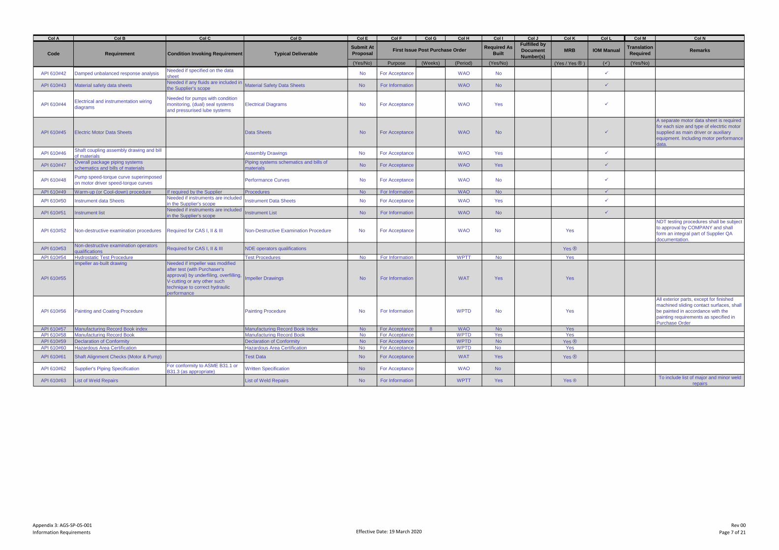
Appendix 3: AGS-SP-05-001Information Requirements Effective Date: 19 March 2020
Rev 00Page 7 of 21
Col A Col B Col C Col D Col E Col F Col G Col H Col I Col J Col K Col L Col M Col N
Submit At
Proposal
Required As
Built
Fulfilled by
Document
Number(s)
MRB IOM ManualTranslation
RequiredRemarks
(Yes/No) Purpose (Weeks) (Period) (Yes/No) (Yes / Yes ® ) () (Yes/No)
Code Requirement Condition Invoking Requirement Typical DeliverableFirst Issue Post Purchase Order
API 610#42 Damped unbalanced response analysisNeeded if specified on the data
sheetNo For Acceptance WAO No
API 610#43 Material safety data sheetsNeeded if any fluids are included in
the Supplier's scopeMaterial Safety Data Sheets No For Information WAO No
API 610#44Electrical and instrumentation wiring
diagrams
Needed for pumps with condition
monitoring, (dual) seal systems
and pressurised lube systems
Electrical Diagrams No For Acceptance WAO Yes
API 610#45 Electric Motor Data Sheets Data Sheets No For Acceptance WAO No
A separate motor data sheet is required
for each size and type of electrtic motor
supplied as main driver or auxiliary
equipment. Including motor performance
data.
API 610#46Shaft coupling assembly drawing and bill
of materialsAssembly Drawings No For Acceptance WAO Yes
API 610#47Overall package piping systems
schematics and bills of materials
Piping systems schematics and bills of
materialsNo For Acceptance WAO Yes
API 610#48Pump speed-torque curve superimposed
on motor driver speed-torque curvesPerformance Curves No For Acceptance WAO No
API 610#49 Warm-up (or Cool-down) procedure If required by the Supplier Procedures No For Information WAO No
API 610#50 Instrument data SheetsNeeded if instruments are included
in the Supplier's scopeInstrument Data Sheets No For Acceptance WAO Yes
API 610#51 Instrument listNeeded if instruments are included
in the Supplier's scopeInstrument List No For Information WAO No
API 610#52 Non-destructive examination procedures Required for CAS I, II & III Non-Destructive Examination Procedure No For Acceptance WAO No Yes
NDT testing procedures shall be subject
to approval by COMPANY and shall
form an integral part of Supplier QA
documentation.
API 610#53Non-destructive examination operators
qualificationsRequired for CAS I, II & III NDE operators qualifications Yes ®
API 610#54 Hydrostatic Test Procedure Test Procedures No For Information WPTT No Yes
API 610#55
Impeller as-built drawing Needed if impeller was modified
after test (with Purchaser's
approval) by underfiling, overfilling,
V-cutting or any other such
technique to correct hydraulic
performance
Impeller Drawings No For Information WAT Yes Yes
API 610#56 Painting and Coating Procedure Painting Procedure No For Information WPTD No Yes
All exterior parts, except for finished
machined sliding contact surfaces, shall
be painted in accordance with the
painting requirements as specified in
Purchase Order
API 610#57 Manufacturing Record Book index Manufacturing Record Book Index No For Acceptance 8 WAO No Yes
API 610#58 Manufacturing Record Book Manufacturing Record Book No For Acceptance WPTD Yes Yes
API 610#59 Declaration of Conformity Declaration of Conformity No For Acceptance WPTD No Yes ®API 610#60 Hazardous Area Certification Hazardous Area Certification No For Acceptance WPTD No Yes
API 610#61 Shaft Alignment Checks (Motor & Pump) Test Data No For Acceptance WAT Yes Yes ®
API 610#62 Supplier's Piping SpecificationFor conformity to ASME B31.1 or
B31.3 (as appropriate)Written Specification No For Acceptance WAO No
API 610#63 List of Weld Repairs List of Weld Repairs No For Information WPTT Yes Yes ®To include list of major and minor weld
repairs
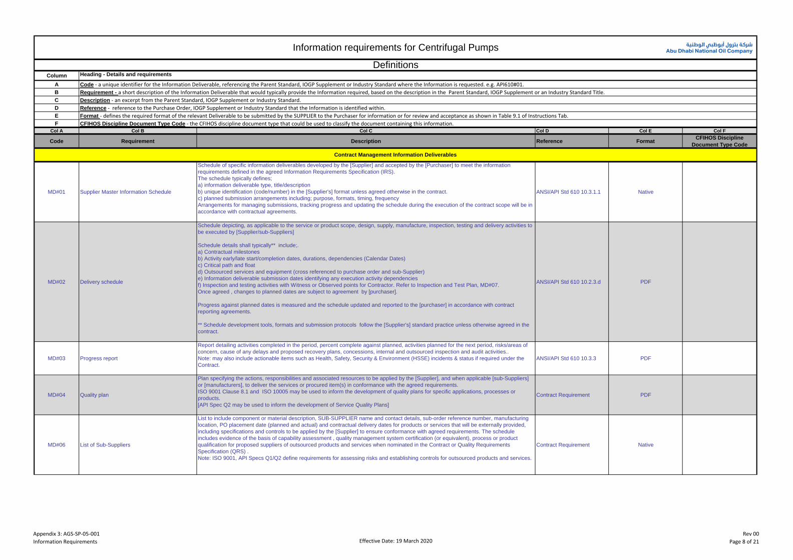
Appendix 3: AGS-SP-05-001Information Requirements Effective Date: 19 March 2020
Rev 00Page 8 of 21
Column
A
B
C
D
E
F
Col A Col B Col C Col D Col E Col F
Code Requirement Description Reference FormatCFIHOS Discipline
Document Type Code
MD#01 Supplier Master Information Schedule
Schedule of specific information deliverables developed by the [Supplier] and accepted by the [Purchaser] to meet the information
requirements defined in the agreed Information Requirements Specification (IRS).
The schedule typically defines;
a) information deliverable type, title/description
b) unique identification (code/number) in the [Supplier's] format unless agreed otherwise in the contract.
c) planned submission arrangements including; purpose, formats, timing, frequency
Arrangements for managing submissions, tracking progress and updating the schedule during the execution of the contract scope will be in
accordance with contractual agreements.
ANSI/API Std 610 10.3.1.1 Native
MD#02 Delivery schedule
Schedule depicting, as applicable to the service or product scope, design, supply, manufacture, inspection, testing and delivery activities to
be executed by [Supplier/sub-Suppliers]
Schedule details shall typically** include;.
a) Contractual milestones
b) Activity early/late start/completion dates, durations, dependencies (Calendar Dates)
c) Critical path and float
d) Outsourced services and equipment (cross referenced to purchase order and sub-Supplier)
e) Information deliverable submission dates identifying any execution activity dependencies
f) Inspection and testing activities with Witness or Observed points for Contractor. Refer to Inspection and Test Plan, MD#07.
Once agreed , changes to planned dates are subject to agreement by [purchaser].
Progress against planned dates is measured and the schedule updated and reported to the [purchaser] in accordance with contract
reporting agreements.
** Schedule development tools, formats and submission protocols follow the [Supplier's] standard practice unless otherwise agreed in the
contract.
ANSI/API Std 610 10.2.3.d PDF
MD#03 Progress report
Report detailing activities completed in the period, percent complete against planned, activities planned for the next period, risks/areas of
concern, cause of any delays and proposed recovery plans, concessions, internal and outsourced inspection and audit activities..
Note: may also include actionable items such as Health, Safety, Security & Environment (HSSE) incidents & status if required under the
Contract.
ANSI/API Std 610 10.3.3 PDF
MD#04 Quality plan
Plan specifying the actions, responsibilities and associated resources to be applied by the [Supplier], and when applicable [sub-Suppliers]
or [manufacturers], to deliver the services or procured item(s) in conformance with the agreed requirements.
ISO 9001 Clause 8.1 and ISO 10005 may be used to inform the development of quality plans for specific applications, processes or
products.
[API Spec Q2 may be used to inform the development of Service Quality Plans]
Contract Requirement PDF
MD#06 List of Sub-Suppliers
List to include component or material description, SUB-SUPPLIER name and contact details, sub-order reference number, manufacturing
location, PO placement date (planned and actual) and contractual delivery dates for products or services that will be externally provided,
including specifications and controls to be applied by the [Supplier] to ensure conformance with agreed requirements. The schedule
includes evidence of the basis of capability assessment , quality management system certification (or equivalent), process or product
qualification for proposed suppliers of outsourced products and services when nominated in the Contract or Quality Requirements
Specification (QRS) .
Note: ISO 9001, API Specs Q1/Q2 define requirements for assessing risks and establishing controls for outsourced products and services.
Contract Requirement Native
Description - an excerpt from the Parent Standard, IOGP Supplement or Industry Standard.
Information requirements for Centrifugal Pumps
DefinitionsHeading - Details and requirements
Code - a unique identifier for the Information Deliverable, referencing the Parent Standard, IOGP Supplement or Industry Standard where the Information is requested. e.g. API610#01.Requirement - a short description of the Information Deliverable that would typically provide the Information required, based on the description in the Parent Standard, IOGP Supplement or an Industry Standard Title.
Reference - reference to the Purchase Order, IOGP Supplement or Industry Standard that the Information is identified within.Format - defines the required format of the relevant Deliverable to be submitted by the SUPPLIER to the Purchaser for information or for review and acceptance as shown in Table 9.1 of Instructions Tab.CFIHOS Discipline Document Type Code - the CFIHOS discipline document type that could be used to classify the document containing this information.
Contract Management Information Deliverables

Appendix 3: AGS-SP-05-001Information Requirements Effective Date: 19 March 2020
Rev 00Page 9 of 21
Col A Col B Col C Col D Col E Col F
Code Requirement Description Reference FormatCFIHOS Discipline
Document Type Code
MD#07 Inspection and Test Plan
Tabular presentation of a quality plan typically used for process or product applications to define the specific sequence of inspection and
testing activities, references to work instructions, acceptance criteria records and associated [Supplier], [purchaser] and independent
conformity assessment activities. Inspection and test activities shall be listed in chronological sequence and shall include activities at sub-
supplier(s) and shall identify them as such. The ITP shall include pre-determined intervention points advised by Contractor to Supplier in
data sheets and/or within Appendix 2. ISO 9001, API Specification Q1 or equivalent quality management system standard (as agreed with
purchaser) may be used to inform the development of inspection and test plans for specific processes and products. The ITP shall include
inspection and testing activities to be performed for the complete package, including those at sub-suppliers’ works and shall make
reference to all testing procedures, control documents, and resulting records and reports. The acceptance criteria shall be clearly defined
within the ITP as indicated within Appendix 2, 'QA Inspection and Testing Requirements' and referenced international codes and standards.
Contract Requirement PDF
MD#08Packing, shipping, storage and preservation
procedure
Definition of practices to be followed during the; storage, transport, lifting and preservation of the equipment and materials included in the
scope of supply to maintain their functionality and guarantees.
Procedures typically define:
a) Packaging requirements; contents, identification, size, weight and number of packages/container (s),
b) special packing/unpacking/handling requirements
c) storage location and requirements,
d) preservation requirements detailing inspection periods and required maintenance, materials required etc., both prior to installation and
post installation, but prior to commissioning.
ANSI/API Std 610 8.4 PDF
MD#09 Non-Conformance Records
Details of non-conformances raised by COMPANY or CONTRACTOR to the [Supplier/sub-Suppliers] against technical requirements prior
to or during the delivery of the products or services. Non-conformance is managed by the [Supplier] in accordance with ISO 9001 Clause
8.7 and associated records typically include; description of non-conformance, analysis and disposition, correction implemented and details
of any retesting or inspection taken to demonstrate subsequent conformance. Note: Instances where the proposed disposition is to accept
a non-conforming condition are subject to agreement by the [purchaser] in accordance with the concession management protocols defined
in the Contract.
Contract Requirement PDF
MD#10 Concession Requests
Formal submission seeking [purchaser] agreement to accept deviations from the contracted scope or technical requirements. Requests
may be raised as a result of, as examples, material or service availability, obsolescence, innovation, non-conformance.
Requests are typically raised as required during execution with a summary report detailing concessions raised, [purchaser] directions,
agreed action status provided with progress reports and at contract closeout
Contract Requirement PDF
MD#11Preservation and Maintenance Instructions for
Insurance/Capital Spares
Detailed instructions for preservation, storage and maintenance of insurance/capital spares (i.e. spare pump rotors, etc) which require
specific controls to be applied. This shall be submitted prior to the packing, shipping storage and preservation procedure, MD#08. Contract Requirement PDF
API 610#01 General Arrangement Drawing(s)
For Proposal: Outline dimensioned drawings for each pump skid, driver and auxiliary systems where applicable including: size and location
of major Purchaser connections; overall dimensions; maintenance clearance dimensions; overall masses; erection masses; maximum
maintenance masses (indicated for each piece), lifting points and methods of lifting the assembled skid package and, if applicable, the
standard baseplate number.
For Acceptance: Certified dimensional outline drawing for each pump major skid, driver and auxiliary systems, where applicable, are to be
provided as per the requirements of 10.3.2.1, L.2.1 a) of ANSI/API Std 610, with the following changes:
- 1) add connection finish; include electrical and instrument connections, where applicable
- 5) add foundation loads; anchor bolt size;
- 7) add forces and moments for other purchaser connections;
- 8) add rigging and lifting plan where applicable.
Drawings are to include full detail of sole plates and anti-vibration mounts (AVMs) where applicable.
ANSI/API Std 610 10.2.2.1.a,
10.2.2.2, 10.3.2.1Native
API 610#02 Pump Performance Curves
As per the requirements of 10.2.4, 10.3.2.2 of ANSI/API Std 610, with the addition, as applicable, of the following:
- all duty points, including the guarantee point;
- for viscous duties, the viscous duty performance curves including maximum expected powers based on worst case cold
start and normal viscous conditions. Performance curves based on water performance are also be provided;
- the curves to be based on the internal clearances proposed by Supplier after making allowances for any added clearance
based on temperature, viscosity, particulates and wear component galling tendencies;
- for pumps with discharge orifices proposed, pump performance curves are to be provided to reflect predicted performance
with and without the orifice installed.
For pumps with Inspection Class I and II, the performance curve shall also show for the rated impeller, variation with respect to flow of
NPSHR 40,000 hrs. Unbalance Radial Load, and Unbalance Thrust loads at twice the design clearances. This information shall also be
included in the as-built performance curve.
ANSI/API Std 610 6.1,
9.3.1.1, 10.2.4PDF
Technical Information Deliverables
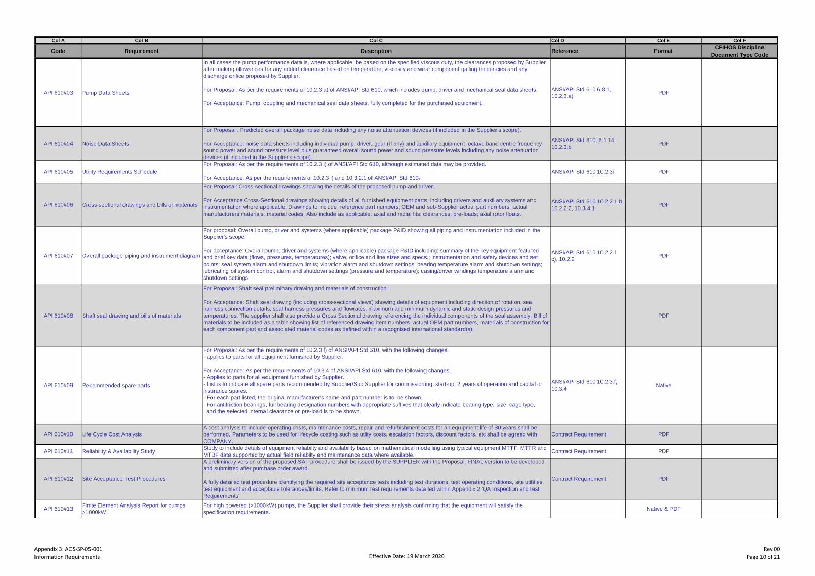
Appendix 3: AGS-SP-05-001Information Requirements Effective Date: 19 March 2020
Rev 00Page 10 of 21
Col A Col B Col C Col D Col E Col F
Code Requirement Description Reference FormatCFIHOS Discipline
Document Type Code
API 610#03 Pump Data Sheets
In all cases the pump performance data is, where applicable, be based on the specified viscous duty, the clearances proposed by Supplier
after making allowances for any added clearance based on temperature, viscosity and wear component galling tendencies and any
discharge orifice proposed by Supplier.
For Proposal: As per the requirements of 10.2.3 a) of ANSI/API Std 610, which includes pump, driver and mechanical seal data sheets.
For Acceptance: Pump, coupling and mechanical seal data sheets, fully completed for the purchased equipment.
ANSI/API Std 610 6.8.1,
10.2.3.a)PDF
API 610#04 Noise Data Sheets
For Proposal : Predicted overall package noise data including any noise attenuation devices (if included in the Supplier's scope).
For Acceptance: noise data sheets including individual pump, driver, gear (if any) and auxiliary equipment octave band centre frequency
sound power and sound pressure level plus guaranteed overall sound power and sound pressure levels including any noise attenuation
devices (if included in the Supplier's scope).
ANSI/API Std 610, 6.1.14,
10.2.3.bPDF
API 610#05 Utility Requirements Schedule
For Proposal: As per the requirements of 10.2.3 i) of ANSI/API Std 610, although estimated data may be provided.
For Acceptance: As per the requirements of 10.2.3 i) and 10.3.2.1 of ANSI/API Std 610.ANSI/API Std 610 10.2.3i PDF
API 610#06 Cross-sectional drawings and bills of materials
For Proposal: Cross-sectional drawings showing the details of the proposed pump and driver.
For Acceptance Cross-Sectional drawings showing details of all furnished equipment parts, including drivers and auxiliary systems and
instrumentation where applicable. Drawings to include: reference part numbers; OEM and sub-Supplier actual part numbers; actual
manufacturers materials; material codes. Also include as applicable: axial and radial fits; clearances; pre-loads; axial rotor floats.
ANSI/API Std 610 10.2.2.1.b,
10.2.2.2, 10.3.4.1PDF
API 610#07 Overall package piping and instrument diagram
For proposal: Overall pump, driver and systems (where applicable) package P&ID showing all piping and instrumentation included in the
Supplier's scope.
For acceptance: Overall pump, driver and systems (where applicable) package P&ID including: summary of the key equipment featured
and brief key data (flows, pressures, temperatures); valve, orifice and line sizes and specs.; instrumentation and safety devices and set
points; seal system alarm and shutdown limits; vibration alarm and shutdown settings; bearing temperature alarm and shutdown settings;
lubricating oil system control, alarm and shutdown settings (pressure and temperature); casing/driver windings temperature alarm and
shutdown settings.
ANSI/API Std 610 10.2.2.1
c), 10.2.2PDF
API 610#08 Shaft seal drawing and bills of materials
For Proposal: Shaft seal preliminary drawing and materials of construction.
For Acceptance: Shaft seal drawing (including cross-sectional views) showing details of equipment including direction of rotation, seal
harness connection details, seal harness pressures and flowrates, maximum and minimum dynamic and static design pressures and
temperatures. The supplier shall also provide a Cross Sectional drawing referencing the individual components of the seal assembly. Bill of
materials to be included as a table showing list of referenced drawing item numbers, actual OEM part numbers, materials of construction for
each component part and associated material codes as defined within a recognised international standard(s).
API 610#09 Recommended spare parts
For Proposal: As per the requirements of 10.2.3 f) of ANSI/API Std 610, with the following changes:
- applies to parts for all equipment furnished by Supplier.
For Acceptance: As per the requirements of 10.3.4 of ANSI/API Std 610, with the following changes:
- Applies to parts for all equipment furnished by Supplier.
- List is to indicate all spare parts recommended by Supplier/Sub Supplier for commissioning, start-up, 2 years of operation and capital or
insurance spares.
- For each part listed, the original manufacturer's name and part number is to be shown.
- For antifriction bearings, full bearing designation numbers with appropriate suffixes that clearly indicate bearing type, size, cage type,
and the selected internal clearance or pre-load is to be shown.
ANSI/API Std 610 10.2.3.f,
10.3.4Native
API 610#10 Life Cycle Cost Analysis
A cost analysis to include operating costs, maintenance costs, repair and refurbishment costs for an equipment life of 30 years shall be
performed. Parameters to be used for lifecycle costing such as utlity costs, escalation factors, discount factors, etc shall be agreed with
COMPANY.
Contract Requirement PDF
API 610#11 Reliability & Availability StudyStudy to include details of equipment reliabilty and availability based on mathematical modelling using typical equipment MTTF, MTTR and
MTBF data supported by actual field reliabilty and maintenance data where available.Contract Requirement PDF
API 610#12 Site Acceptance Test Procedures
A preliminary version of the proposed SAT procedure shall be issued by the SUPPLIER with the Proposal. FINAL version to be developed
and submitted after purchase order award.
A fully detailed test procedure identifying the required site acceptance tests including test durations, test operating conditions, site utilities,
test equipment and acceptable tolerances/limits. Refer to minimum test requirements detailed within Appendix 2 'QA Inspection and test
Requirements'
Contract Requirement PDF
API 610#13Finite Element Analysis Report for pumps
>1000kW
For high powered (>1000kW) pumps, the Supplier shall provide their stress analysis confirming that the equipment will satisfy the
specification requirements. Native & PDF

Appendix 3: AGS-SP-05-001Information Requirements Effective Date: 19 March 2020
Rev 00Page 11 of 21
Col A Col B Col C Col D Col E Col F
Code Requirement Description Reference FormatCFIHOS Discipline
Document Type Code
API 610#14Installation, operation and maintenance
instructions index
Installation, Operation and Maintenance Instructions Index is to be agreed prior to submission of the manual. Each manual and sub-
Supplier manual is to include the below listed sections as a minimum.
Index to also include full sub-indices details. Note that the Installation, Operation and Maintenance Manual is not to contain any SMIR
documents that have been formally submitted to the Purchaser during the contract but listed and referenced.
Section 1 - Installation: as per the requirements of ANSI/API Std 610, L.2.1 cc) 1).
Section 2 - Commissioning, start-up and operation procedures and acceptance criteria: i) lubrication recommendations; ii) pre-
commissioning/pre-start-up checks and tests; iv) operation and shutdown procedures; iii) acceptance checks and tests.
Section 3 - Disassembly and reassembly: as per the requirements of ANSI/API Std 610, L.2.1 cc) 3) with the following change: add ix)
fastener torques.
Section 4 - Any start-up, shutdown or operating restrictions required to protect the integrity of the equipment
Section 5 - Operating procedures for special tools, if any
Section 6 - Driver Installation, Operation and Maintenance Manuals:
Section 7 - Mechanical Seal Installation, Operation and Maintenance Manuals
Section 8 - All auxiliary equipment (add sections as appropriate), Installation, Operation and Maintenance Manuals
Section 9 - Troubleshooting
ANSI/API Std 610 6.4.3.14,
6.11.2, 10.3.5PDF
API 610#15Installation, operation and maintenance
instructions
Provides sufficient information to install, operate and maintain the equipment, as well as sufficient information for troubleshooting.
Description of methods of installing a piece of equipment. Installation refers to the mounting, setting, erection, etc.
Description of methods of maintaining a specific piece of equipment. Typically originates from the equipment or package Supplier.
'Description of methods of operating a piece of equipment or process unit, including but not limited to instructions, procedures, drawings,
tables, etc. for the operation -stop, start, and emergency shutdown. Including operational limits, function testing, possible interruptions,
corrective actions, hazards and corrective measures to be taken.
NOTE: Unless otherwise agreed, can be delivered in manufacturer's standard manual or as one or several documents clearly marked
which part they cover (I, O, M)
The following additional data shall be included within the Installation Operating and Maintenance Manuals and is applicable only to single
stage overhung pumps and single stage impeller between bearings pumps:
1) For single stage overhung pumps, shaft diameter under shaft sleeve and axial distance from radial bearing centreline to midpoint of
impeller discharge area at the outside diameter.
2) For single stage impeller between bearings pumps, distance between bearing centrelines.
3) Maximum radial shaft deflection shall be stated in proposal.
ANSI/API Std 610 6.4.3.14
6.11.2, 10.3.5PDF
API 610#16Shaft and rotor total indicator (TIR) reading
certificates
Certificates detailing all shaft run-out checks, including phase relation for each displacement probe location on pumps, motors, steam
turbines and gear units.
ANSI/API Std 610 6.6,
9.3.3.1, 9.3.12.2.d, Table 17,
Table 19
API 610#17 Wear part running clearance certificatesCertificates detailing all as-built close clearances and those specified at Purchase. ANSI/API Std 610 Table 6;
6.7.4PDF
API 610#18 Torsional critical speed analysisAs per the requirements of 6.9.2.10 of ANSI/API Std 610.
ANSI/API Std 610 6.9.2.10 PDF
API 610#19 Performance Test ReportsAs per the requirements of L.2.1 u) of ANSI/API Std 610, with the following change:
- performance test data is to include Fast Fourier Transform spectra for each test point.
ANSI/API Std 610 6.9.3,
8.3.3, 10.3.2.2PDF
API 610#20 Rotating component balancing certificatesThe certificate to be provided by the manufacturer recording the results of the balancing of all rotating elements to the specified grade in
accordance with the Purchaser accepted balancing procedure. To include residual unbalance check.
ANSI/API Std 610 6.9.4,
9.1.3.7, 9.2.4PDF
API 610#21 Non-destructive examination records
Detailed non-destructive examination reports describing procedure used, results obtained and action for visual, radiographic, ultrasonic,
magnetic particle, and dye-penetrant examinations. Reports shall be signed and dated by an authorized operator and identify components
tested, location, heat-treated condition, and other requirements per Project specifications.
ANSI/API Std 610 6.12.1.5,
8.2.1.3PDF
API 610#22 Material Certificates
Certificate type shall be as required by the QRS/Project requirements. Material test certificates shall include as a minimum chemical
analysis, mechanical test results and heat treatment condition. Additional data to satisfy Project requirements.
ANSI/API Std 610 6.12.1.8,
6.12.4.3, 8.2.2.7, Annex H
Tables H.2 and H.4
API 610#23Weld procedures, procedure qualification
records and weld maps
WPSs and PQRs proposed for each different weld and materials type including weld maps to clearly show the location and type of the
proposed weld.
For proposed major weld repairs, weld repair maps showing location and major dimensions of weld repair cavities, qualification records,
drawings, photographs, heat treatment detail, NDE requirements and other specified documents are also be submitted.
ANSI/API Std 610 6.12.2,
6.12.3, 6.12.4 PDF
API 610#24Surface preparation and painting inspection
certificates
Certification confirming that the unpainted equipment meets the visual requirements of MSS SP-55.
Certificate to include Purchaser's PO number; item or tag number, and shall verify that painting and/or insulation is in accordance with the
Purchaser's specifications or the Purchaser accepted specifications, as applicable. To include intermediate coat number/checks,
temperature, humidity, DFT, coverage/opacity, colour etc. and signed by the painting/insulation contractor.
ANSI/API Std 610 6.12.2.1,
7.3.12, 8.4.2.4, 9.3.8.3.3PDF
API 610#25 Major weld repair certificatesCertification that major weld repairs have been satisfactorily completed and inspected according to the same quality standard used to
inspect the casting.
ANSI/API Std 610 6.12.2.3,
6.12.2.5PDF
API 610#26 Welders qualifications
Qualification of all welders or welding operators using approved weld procedures and by weld position in accordance with project
specifications. Welders name, identification and positions to be recorded to code requirements with approval by third party inspection
authority when applicable.
ANSI/API Std 610 Table 11 PDF
API 610#27 Heat treatment certificates
Scanned Original or wet stamped verified copies of pyrometric charts or certificates confirming the heat treatment cycles have been
conducted to the Purchaser's/Material specification's requirements. To include charts for any heat treatment conducted such as, during
forming, normalising, quenching, post-weld heat treatment, rotor heat stability testing.
Certificates to state PO number, item number, and identification to permit traceability to the heat-treated component or materials.
ANSI/API Std 610 Table 11 PDF

Appendix 3: AGS-SP-05-001Information Requirements Effective Date: 19 March 2020
Rev 00Page 12 of 21
Col A Col B Col C Col D Col E Col F
Code Requirement Description Reference FormatCFIHOS Discipline
Document Type Code
API 610#28 Nameplate DrawingNameplate data content is to be as per API 610 clause 6.13.2/S-615 clause 6.13.2. Font size minimum 5mm. Nameplate language per PO.
ANSI/API Std 610 6.13.2 PDF
API 610#29 Baseplate flatness and coplanarity certificatesCertification confirming that all the machinery mounting pads of the baseplate have been fully machined flat and that their surfaces are in
the same plane within 150 μm/m (0,002 in/ft) of distance between the pads. ANSI/API Std 610 7.3 PDF
API 610#30 Nozzle forces and moments testing certificatesCertification confirming that when subjected to moments MYc and MZc applied to either nozzle, the shaft displacement the drive end or at
the register fit of the coupling hub are within the values shown in ANSI/API Std 610 11th ed., Table 13.ANSI/API Std 610 7.3.21 PDF
API 610#31 Special tools listList of special tools and fixtures which are required to disassemble, assemble, or maintain the supplied equipment. ANSI/API Std 610 7.6,
10.2.3.gPDF
API 610#32 Positive material identification certificatesCertification that the alloying element percentages of materials subject to verification are in accordance with the proposed recognised
material specification.ANSI/API Std 610 8.2.2.8 PDF
API 610#33 Factory Acceptance Test Procedure(s)
As per the requirements of 8.3.1.1, 8.3.1.2, 8.3.3.3 of ANSI/API Std 610 with the following change:
- add description of the test setup and instrumentation.
SUPPLIER to submit test procedures for performance test, mechanical run test and/or complete unit test if specified within the pump data
sheets. Test procedures shall identify full details of shop test and measuring equipment to be used, subject to COMPANY approval.
ANSI/API Std 610 8.3.1,
8.3.3, 8.3.4, 9.3.9.1PDF
API 610#34 Auxiliary Equipment Test Procedures
Procedures for all optional tests (when specified in the data sheet) to determine that equipment is satisfactory for the specified service and
meets all Purchaser requirements. Auxiliary equipment test procedures including Lube Oil System, Gearbox, electric motor(s), etc if
specified within the pump data sheets.
ANSI/API Std 610 8.3.1,
8.3.4, 10.2.3 j), 10.2.5PDF
API 610#35 Certified hydrostatic test dataCertified Hydrostatic Test Data at a minimum of 1.5 times the maximum allowable working pressure including full details of any areas
machined post hydrotest.ANSI/API Std 610 8.3.2 PDF
API 610#36 Disassembly after testing certificatesCertification that the condition of the pump internals after all running testing has not been adversely affected to the extent that they are
outside the acceptance criteria of their 'as new' condition.ANSI/API Std 610 8.3.3.8 PDF
API 610#37 Auxillairy Equipment Data SheetsAuxiliary equipment data sheets covering Lube Oil System, Gearbox, Coupling, Mechanical Seal, etc ANSI/API Std 610 8.3.1,
8.3.4, 10.2.3 j), 10.2.5PDF
API 610#38 Lubrication schedule
The lubricant table is to indicate, for each complete unit and for each device or point to be lubricated, the following data:
- Make and tag of the lubricant to be utilized and of other makes, if required in the Project specifications;
- Physical and chemical characteristics sufficient to define the equivalency with others (viscosity at 50°C, specific gravity, index of viscosity,
etc.)
- The quantity of lubricant required
- The required pressure of the lubricant (if applicable)
- The heat load being removed by the lubricant (if applicable)
- Expected yearly consumption according to the experience of the Supplier.
ANSI/API Std 610 10.2.3i PDF
API 610#39 Structural Resonance Test Certificates PDF
API 610#40Inspection and test equipment calibration
certificates
Current calibration certificates for all shop instrumentation to be used during inspection and testing activities.ANSI/API Std 610 10.3.2.2 PDF
API 610#41 Lateral critical speed analysis As per the requirements of I.3 of ANSI/API Std 610. ANSI/API Std 610 Annex I PDF
API 610#42 Damped unbalanced response analysis As per the requirements of I.1.4 of ANSI/API Std 610. ANSI/API Std 610 Annex I PDF
API 610#43 Material safety data sheetsMaterial safety data sheets are to be in accordance with local standards for the specific paints, preservatives, coatings, lubricants, cooling
media and chemicals supplied with, or applied to the supplied machinery or equipment. E.g. OSHA Form 174.PDF
API 610#44 Electrical and instrumentation wiring diagrams
The Supplier standard drawings are to be submitted. The diagrams are also to show the connections, terminal/pin/socket and cable detail
between different items within the package, including earthing and spare terminals. The diagram is also identify all connections to
Purchaser's power supply and instrumented systems.
API 610#45 Electric Motor Data Sheets As per the requirements of L.2.2 e) of ANSI/API Std 610. PDF
API 610#46Shaft coupling assembly drawing and bill of
materials
Shaft coupling assembly drawing and bill of materials, including coupling specification, fit, full dimensions, allowable misalignment
tolerances, balance grade, service factor, weights, machining/mounting details, keys detail and maintenance details.
The coupling drawing is to include coupling thermal growth data in millimetres per 100°C temperature rise as applicable.
API 610#47Overall package piping systems schematics
and bills of materials
Overall pump and driver package piping systems schematics and bills of material including as applicable for all systems: applicable WPS
(fabrications); parts list; quantities; sizes; dimensions; specifications; materials of construction.PDF
API 610#48Pump speed-torque curve superimposed on
motor driver speed-torque curves
Pump speed-torque curve superimposed on the motor driver speed-torque curvesANSI/API Std 610 7.1.6 PDF
API 610#49 Warm-up (or Cool-down) procedureDetailed procedure to be followed to achieve instantaneous start-up of the pump with the pumping temperatures indicated on the data
sheet.PDF
API 610#50 Instrument data Ssheets Purchaser's format instrument data sheets, fully completed. PDF
API 610#51 Instrument list Instrument list with tag nos., service descriptions, ranges, alarm and trip set points (if any) PDF
API 610#52 Non-destructive examination proceduresWritten description of all essential parameters and precautions to be applied when non-destructively testing products in accordance with
standard(s), code(s) or specification(s)ANSI/API Std 610 8.2.2 PDF
API 610#53Non-destructive examination operators
qualifications
Qualification certificates for the technicians and operators signing certificates are required. NDE Operators are required to be qualified by
an authorized qualification body such as to PCN, CSWIP, SNT-TC-1A, or other Purchaser approved standard according to EN ISO
9712/ISO 9712 for radiographic, ultrasonic, magnetic particle and dye penetrant examination. An index is required for all NDE Operators
providing Name, Identification, Qualifications, Start and Expiry Dates of Qualifications
ASME BPVC, Article 1,
Section VPDF
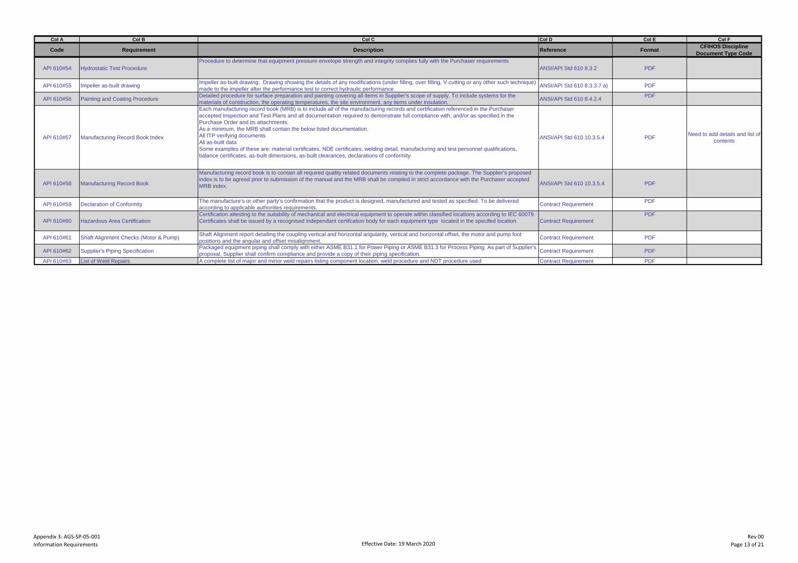
Appendix 3: AGS-SP-05-001Information Requirements Effective Date: 19 March 2020
Rev 00Page 13 of 21
Col A Col B Col C Col D Col E Col F
Code Requirement Description Reference FormatCFIHOS Discipline
Document Type Code
API 610#54 Hydrostatic Test Procedure
Procedure to determine that equipment pressure envelope strength and integrity complies fully with the Purchaser requirements
ANSI/API Std 610 8.3.2 PDF
API 610#55 Impeller as-built drawingImpeller as-built drawing. Drawing showing the details of any modifications (under filling, over filling, V-cutting or any other such technique)
made to the impeller after the performance test to correct hydraulic performance.ANSI/API Std 610 8.3.3.7 a) PDF
API 610#56 Painting and Coating ProcedureDetailed procedure for surface preparation and painting covering all items in Supplier's scope of supply. To include systems for the
materials of construction, the operating temperatures, the site environment, any items under insulation.ANSI/API Std 610 8.4.2.4
API 610#57 Manufacturing Record Book Index
Each manufacturing record book (MRB) is to include all of the manufacturing records and certification referenced in the Purchaser
accepted Inspection and Test Plans and all documentation required to demonstrate full compliance with, and/or as specified in the
Purchase Order and its attachments.
As a minimum, the MRB shall contain the below listed documentation.
All ITP verifying documents
All as-built data
Some examples of these are: material certificates, NDE certificates, welding detail, manufacturing and test personnel qualifications,
balance certificates, as-built dimensions, as-built clearances, declarations of conformity.
ANSI/API Std 610 10.3.5.4 PDFNeed to add details and list of
contents
API 610#58 Manufacturing Record Book
Manufacturing record book is to contain all required quality related documents relating to the complete package. The Supplier's proposed
index is to be agreed prior to submission of the manual and the MRB shall be compiled in strict accordance with the Purchaser accepted
MRB index.ANSI/API Std 610 10.3.5.4 PDF
API 610#59 Declaration of ConformityThe manufacture’s or other party’s confirmation that the product is designed, manufactured and tested as specified. To be delivered
according to applicable authorities requirements.Contract Requirement
API 610#60 Hazardous Area Certification
Certification attesting to the suitability of mechanical and electrical equipment to operate within classified locations according to IEC 60079.
Certificates shall be issued by a recognised independant certifcation body for each equipment type located in the specifed location. Contract Requirement
API 610#61 Shaft Alignment Checks (Motor & Pump)Shaft Alignment report detailing the coupling vertical and horizontal angularity, vertical and horizontal offset, the motor and pump foot
positions and the angular and offset misalignment. Contract Requirement PDF
API 610#62 Supplier's Piping SpecificationPackaged equipment piping shall comply with either ASME B31.1 for Power Piping or ASME B31.3 for Process Piping. As part of Supplier's
proposal, Supplier shall confirm compliance and provide a copy of their piping specification.Contract Requirement PDF
API 610#63 List of Weld Repairs A complete list of major and minor weld repairs listing component location, weld procedure and NDT procedure used Contract Requirement PDF
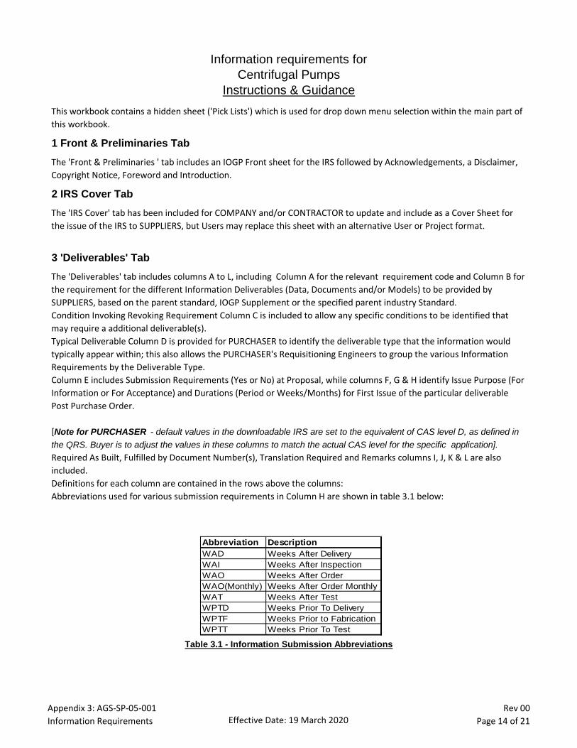
Appendix 3: AGS-SP-05-001Information Requirements Effective Date: 19 March 2020
Rev 00Page 14 of 21
Information requirements for
Centrifugal Pumps
Instructions & Guidance
This workbook contains a hidden sheet ('Pick Lists') which is used for drop down menu selection within the main part of this workbook.
1 Front & Preliminaries Tab
The 'Front & Preliminaries ' tab includes an IOGP Front sheet for the IRS followed by Acknowledgements, a Disclaimer, Copyright Notice, Foreword and Introduction.
2 IRS Cover Tab
The 'IRS Cover' tab has been included for COMPANY and/or CONTRACTOR to update and include as a Cover Sheet for the issue of the IRS to SUPPLIERS, but Users may replace this sheet with an alternative User or Project format.
3 'Deliverables' Tab
The 'Deliverables' tab includes columns A to L, including Column A for the relevant requirement code and Column B for the requirement for the different Information Deliverables (Data, Documents and/or Models) to be provided by SUPPLIERS, based on the parent standard, IOGP Supplement or the specified parent industry Standard. Condition Invoking Revoking Requirement Column C is included to allow any specific conditions to be identified that may require a additional deliverable(s). Typical Deliverable Column D is provided for PURCHASER to identify the deliverable type that the information would typically appear within; this also allows the PURCHASER's Requisitioning Engineers to group the various Information Requirements by the Deliverable Type. Column E includes Submission Requirements (Yes or No) at Proposal, while columns F, G & H identify Issue Purpose (For Information or For Acceptance) and Durations (Period or Weeks/Months) for First Issue of the particular deliverable Post Purchase Order.
[Note for PURCHASER - default values in the downloadable IRS are set to the equivalent of CAS level D, as defined in the QRS. Buyer is to adjust the values in these columns to match the actual CAS level for the specific application].Required As Built, Fulfilled by Document Number(s), Translation Required and Remarks columns I, J, K & L are also included.Definitions for each column are contained in the rows above the columns:Abbreviations used for various submission requirements in Column H are shown in table 3.1 below:
Table 3.1 - Information Submission Abbreviations
Abbreviation Description
WAD Weeks After Delivery
WAI Weeks After Inspection
WAO Weeks After Order
WAO(Monthly) Weeks After Order Monthly
WAT Weeks After Test
WPTD Weeks Prior To Delivery
WPTF Weeks Prior to Fabrication
WPTT Weeks Prior To Test
Appendix 3: AGS-SP-05-001Information Requirements Effective Date: 19 March 2020
Rev 00Page 15 of 21
4 'Definitions' Tab
The 'Definitions' tab includes several columns A to F, including Column A for the relevant Code & Column B for the Requirement for the different Information (Data, Documents and/or Models) Deliverables to be provided by SUPPLIER's, all copied from the 'Deliverables' tab.Column C includes a full description of the Information Deliverable based on the Parent Standard or relevant Industry Standard.Column D gives a reference to the Purchase Order or Industry Standard that the Information is identified within.Column E identifies the Deliverable format as listed in Table 9.1 below.Column F relates the CFIHOS discipline document type that could be used to classify the document having this IRS content. Definitions for each column are contained in the rows above the columns.
5 'Instructions' Tab
This 'Instructions' tab is provided to instruction & guidance to COMPANY, CONTRACTOR, PURCHASER and/or SUPPLIERS in the use of this IRS.
6 Abbreviations and Definitions
The following abbreviations, terms and definitions have been used in the various tabs of this workbook:
PURCHASER: Organisation placing a Contract or Purchase Order with Supplier for equipment or services on project; may be alternatively referred to as 'User' or 'Purchaser'CFIHOS: Capital Facilities Information Hand Over SpecificationCOMPANY: Project Owner and/or Operator or other body acting on their behalfCONTRACTOR: Nominated Contractor responsible for engineering, procurement of materials, building/installation and commissioning of the plant.Information: Data Sheets, Documents, Drawings and/or PDMS ModelsIRS: Information Requirements SpecificationPO: Purchase OrderQRS: Quality Requirements Specification (QA Inspection and Testing Requirements - Appendix 2)SMIS: Supplier Master Information ScheduleSUPPLIER: Organisation supplying equipment or services to Company and/or Contractor on project; may alternatively be referred to as "Supplier", "Seller" or “Manufacturer”.
7 CFIHOS
The Information Requirements and Deliverables described in this IRS are based on the CFIHOS (Capital Facilities Information Hand Over Specification) Industry Standard. The objective of CFIHOS is to create a common information standard across the Oil and Gas industry to facilitate efficient information exchange on projects. Further information on CFIHOS can be found at http://uspi-global.org/index.php/projects/frameworks-methodologies/136-cfihos
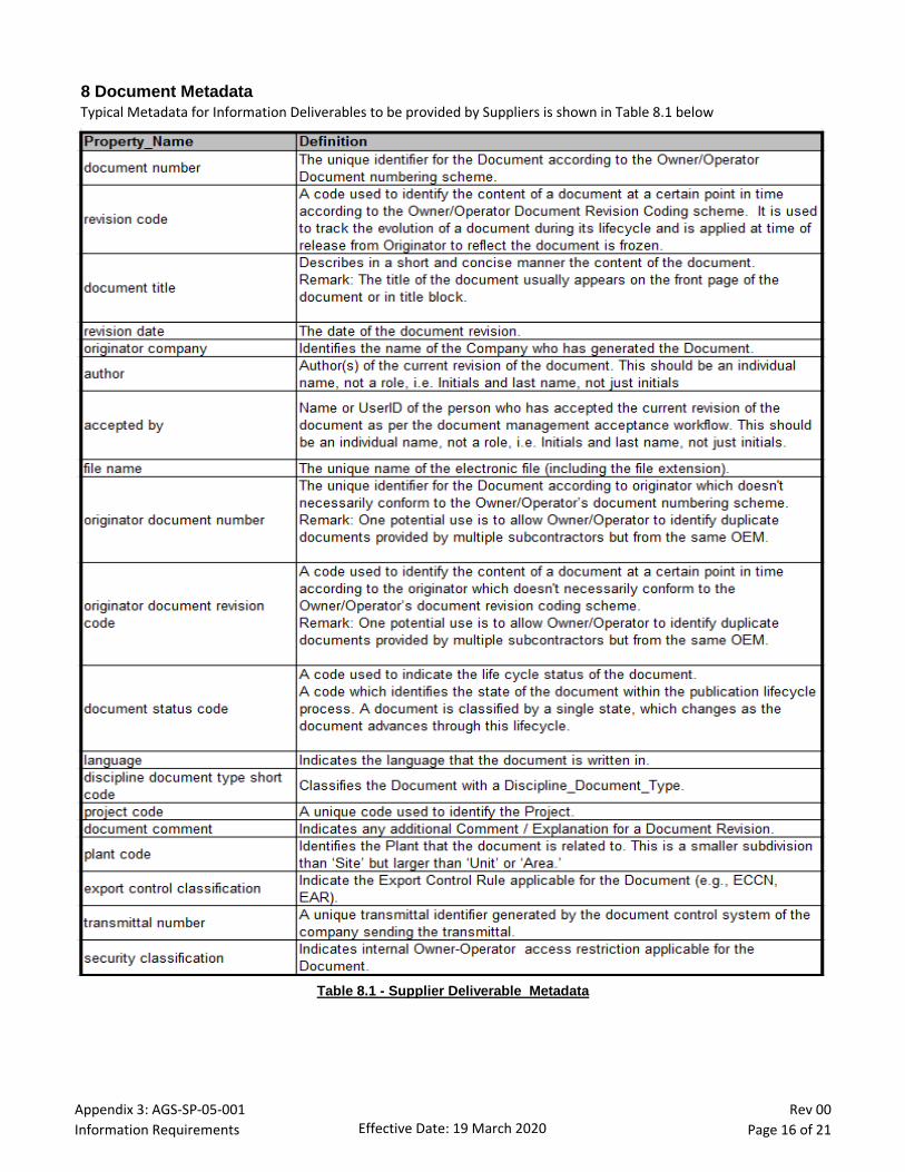
Appendix 3: AGS-SP-05-001Information Requirements Effective Date: 19 March 2020
Rev 00Page 16 of 21
8 Document Metadata
Typical Metadata for Information Deliverables to be provided by Suppliers is shown in Table 8.1 below
Table 8.1 - Supplier Deliverable Metadata
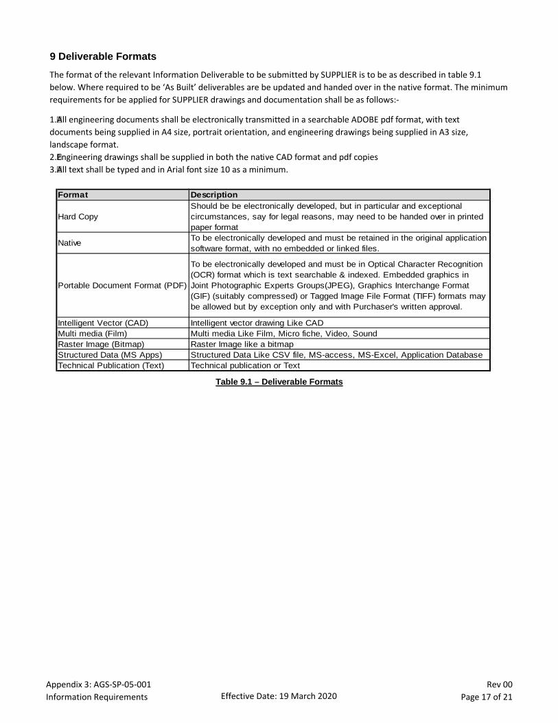
Appendix 3: AGS-SP-05-001Information Requirements Effective Date: 19 March 2020
Rev 00Page 17 of 21
9 Deliverable Formats
The format of the relevant Information Deliverable to be submitted by SUPPLIER is to be as described in table 9.1 below. Where required to be ‘As Built’ deliverables are be updated and handed over in the native format. The minimum requirements for be applied for SUPPLIER drawings and documentation shall be as follows:-
1.All engineering documents shall be electronically transmitted in a searchable ADOBE pdf format, with text documents being supplied in A4 size, portrait orientation, and engineering drawings being supplied in A3 size, landscape format. 2.Engineering drawings shall be supplied in both the native CAD format and pdf copies3.All text shall be typed and in Arial font size 10 as a minimum.
Table 9.1 – Deliverable Formats
Format Description
Hard Copy
Should be be electronically developed, but in particular and exceptional
circumstances, say for legal reasons, may need to be handed over in printed
paper format
NativeTo be electronically developed and must be retained in the original application
software format, with no embedded or linked files.
Portable Document Format (PDF)
To be electronically developed and must be in Optical Character Recognition
(OCR) format which is text searchable & indexed. Embedded graphics in
Joint Photographic Experts Groups(JPEG), Graphics Interchange Format
(GIF) (suitably compressed) or Tagged Image File Format (TIFF) formats may
be allowed but by exception only and with Purchaser's written approval.
Intelligent Vector (CAD) Intelligent vector drawing Like CAD
Multi media (Film) Multi media Like Film, Micro fiche, Video, Sound
Raster Image (Bitmap) Raster Image like a bitmap
Structured Data (MS Apps) Structured Data Like CSV file, MS-access, MS-Excel, Application Database
Technical Publication (Text) Technical publication or Text

Appendix 3: AGS-SP-05-001Information Requirements Effective Date: 19 March 2020
Rev 00Page 18 of 21
Issu
e
2 Tag No. : Insert Tag_No
3 Service : Insert Service Description
4
5 API Clause Ref. Description of Amendment
6 6.1 Basic Design - General
7 6.1.16
(Add)
If the offered pump is beyond the boundary conditions (operating above 3600 RPM and absorbing more than 300kW per stage) as
stated in this clause, the SUPPLIER shall indicate the clearance and special construction features in the proposal and provide
operating experience for the same.
8 6.1.36
(New)
For multistage pumps, the SUPPLIER shall present during the bid clarification meeting(s) his in-house design data, including
stress analysis of pressure casings.
9 6.8 Basic Design - Mechanical Shaft Seals
10 6.8.14
(New)
Dual pressurized seals shall be applied for the following services as a minimum:
a. Hazardous service/toxic fluids (see note below).
b. Services containing H2S % equal to or higher than 500 ppm.
c. Operating temperature higher than 177°C.
d. High vapor pressure, light hydrocarbons.
e. Dirty/Abrasive/Polymerizing fluids.
API 682, Plan 74 shall be explored for all VS4 pumps types in sour service where a sufficiently clean source of nitrogen is
available. The SUPPLIER shall state the guaranteed nitrogen consumption within the technical bid as part of the submitted “Utility
Requirements” list as noted within Appendix 3, ‘Information Requirements’.
11 6.9 Basic Design - Dynamics
12 6.9.1.4
(New)
SUPPLIER information and input required to enable the COMPANY to perform an independent rotordynamic analysis shall be
provided where requested.
It is the COMPANY’s decision to consider if an independent rotordynamic analysis is required.
Typically this would be required for the following cases and this requirement shall be clarified during the bid clarification meeting:
-Synchronous motor rated 500 kW or higher;
-Electric motor with variable-frequency drive (VFD) rated 1000 kW or higher.
13 6.1 Basic Design - Bearings and Bearing Housings
14 6.10.1.2
(Add)
When hydrodynamic thrust bearings are proposed, the following shall apply:
a. Pump hydraulic design shall be such that the axial loads are unidirectional under all operating conditions. Thrust bearing shall
be capable to stand transient thrust condition may also occur.
b. SUPPLIER shall submit in his bid, curves showing the variation of axial load with capacity (zero flow to EOC flow) for design
internal clearances and two times design internal clearances. For variable speed units, similar curve for maximum continuous
speed and minimum speed shall be submitted.
15 6.10.1.6
(Modify)
Replace first sentence with…. “Bearing system life (the calculated life of the combined system of bearings in the pump) shall be
equivalent to at least 40 000 h under continuous operation at rated conditions, and at least 16 000 h at maximum radial and axial
loads and rated speed.”
Bearing System Life calculations shall be supplied for High Energy Pumps.
##
USER SUPPLEMENTARY REQUIREMENTS
Information Requirements for Centrifugal Pumps

Appendix 3: AGS-SP-05-001Information Requirements Effective Date: 19 March 2020
Rev 00Page 19 of 21
Issue
2 Tag No. : Insert Tag_No
3 Service : Insert Service Description
4 USER SUPPLEMENTARY REQUIREMENTS
5 API Clause Ref. Description of Amendment
6 10 Supplier's Data
7 10.1.1
(Add)
Technical data, registers, documents, and drawings that together define the scope of the Purchase Order shall conform to the
requirements for supplier information identified in the Purchase Order. The SUPPLIER shall comply with the following minimum
requirements concerning submission of drawings and documentation:-
- EM 30.99.95.0006 - ADCO Guidelines for Submission of Electronic Documentation
- EP 30.99.90.0024 - Preparation of Supplier’s/Supplier’s Engineering Drawings and Documents
8 10.1.3
(Modification)
The first sentence shall be modified to read "A SUPPLIER co-ordination meeting shall be held, preferably at the SUPPLIER's
works, within four to six weeks after order commitment with the Purchaser's Engineer in attentance."
9 10.2.1 Proposals / General
10 10.2.1.1(Add) The SUPPLIER's proposal shall clearly state whether or not the offered equipment is in full compliance with the listed
specifications. Where applicable, the SUPPLIER shall include a list in the proposal that details and explains each deviation.
11 10.2.1.3 (New) Driver, if offered, shall be included in proposal with separate price.
12 10.2.3 Technical Data
13 10.2.3a)
(Add)
Motor data sheets for each selected electric motor driver offered by the SUPPLIER shall also be included, which shall identify the
electrical supply requirements and other special motor requirements.
14 10.2.3f)
(Add) Spare parts for commissioning and two years operation are required in accordance with API 610 11th Edition; Table 20 as
a minimum. Capital spares are required only when there is no installed standby pump and in this case, the below additional
spares are to be included within the SUPPLIER's proposal:-
a. Complete shaft, impellers etc. for normal pumps and inner barrel bundle if barrel type in a container
Commissioning spares: (If they are not used, handover to COMPANY)
a. Seal cartridge shall be supplied as mandatory commissioning spare and not as a capital spare (one set per pump tag)
b. Set of bearings shall be supplied as mandatory commissioning spare and not as a capital spare (one set per pump tag)
For balance of pumps, they can be covered under 2Y spares (List only during EPC bid and later supply after SPIR submission
and check within stocks for interchangeability). Commissioning spares to be included in scope.
15 10.2.3I) (Deletion) Delete the words “If specified”.
16 10.2.3q)
(New)
q) For high energy pumps, defined as 750kW motor rating and above, SUPPLIER shall provide:-
1) Engineering and test data to substantiate the ability of high energy per stage pumps (as defined by 6.1.15) to operate down
to minimum specified flow without:
(a) Excessive thrust load or exceeding allowable vibration limits (see 6.9.3).
(b) Use of a bypass.
2) Minimum continuous flow. If no minimum flow is specified, 40% of BEP shall be used.
3) Pump may be offered with bypass if required. In this case, the proposal shall clearly state flow conditions under which
bypass shall operate as follows:
(a) Size of required bypass orifice shall be specified.
(b) Orifice will be provided and installed by COMPANY.
4) Demonstration that hydraulic design minimises wear and erosion.
5) Maximum head rise across impellers.
6) Maximum leakage velocity across labyrinth seals and balance piston.
17 10.2.3r)(Add)
r) details of impeller securing method. This may be included within pump data sheet.
Information Requirements for Centrifugal Pumps

Appendix 3: AGS-SP-05-001Information Requirements Effective Date: 19 March 2020
Rev 00Page 20 of 21
Issue
2 Tag No. : Insert Tag_No
3 Service : Insert Service Description
4 USER SUPPLEMENTARY REQUIREMENTS
5 API Clause Ref. Description of Amendment
Information Requirements for Centrifugal Pumps
18 10.2.4 Curves
19
(Add)
The pump performance curves shall reflect the following additional requirements:-
a. An orifice plate shall not be used to achieve continuously rising head to shutoff.
b. Pumps with suction specific speed greater than criteria defined in this specification shall have a “stability window” indicated on
the performance curve.
c. Satisfactory continuous operation over full operation range shall be guaranteed. Operating range shall be defined as the range
covered by head capacity curve provided with proposal.
d. NPSH3 curve, as well as onset of internal recirculation, shall be considered if specifying minimum continuous stable flow.
e. Limiting conditions to operation over the range shown by curve shall be indicated on the curve.
f. Axial load data shall be included
g. Performance curves shall show the pump shaft power requirement across the entire flow range, from shutoff to maximum
capacity.
Appendix 3: Information Requirements
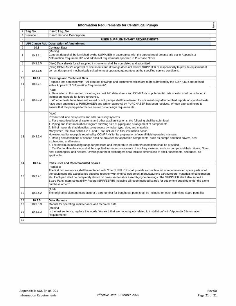
Appendix 3: AGS-SP-05-001Information Requirements Effective Date: 19 March 2020
Rev 00Page 21 of 21
Issue
2 Tag No. : Insert Tag_No
3 Service : Insert Service Description
4 USER SUPPLEMENTARY REQUIREMENTS
5 API Clause Ref. Description of Amendment
6 10.3 Contract Data
7 10.3.1.1
(Modify)
Contract data shall be furnished by the SUPPLIER in accordance with the agreed requirements laid out in Appendix 3
"Information Requirements" and additional requirements specified in Purchase Order.
8 10.3.1.5 (New) Data sheets for all supplied instruments shall be completed and submitted.
9 10.3.1.6
(New) COMPANY’s approval of documents and drawings does not relieve SUPPLIER of responsibility to provide equipment of
correct design and mechanically suited to meet operating guarantees at the specified service conditions.
10 10.3.2 Drawings and Technical Data
11 10.3.2.1(Replace last sentence with) "All contract drawings and documents which are to be submitted by the SUPPLIER are defined
within Appendix 3 "Information Requirements".
12 10.3.2.2
(Add)
a. Data listed in this section, including as built API data sheets and COMPANY supplemental data sheets, shall be included in
instruction manuals for future reference.
b. Whether tests have been witnessed or not, pumps shall be released for shipment only after certified reports of specified tests
have been submitted to PURCHASER and written approval by PURCHASER has been received. Written approval helps to
ensure that the pump performance conforms to design requirements.
13 10.3.2.4
(New)
Pressurised lube oil systems and other auxiliary systems
a. For pressurised lube oil systems and other auxiliary systems, the following shall be submitted:
1. Piping and Instrumentation Diagram showing size of piping and arrangement of components.
2. Bill of materials that identifies components by make, type, size, and materials.
Many times, the data defined in 1. and 2. are included in final instruction books.
However, earlier receipt is required by COMPANY for its preparation of overall field operating manuals.
b. Rating and conditions of service shall be provided for applicable components, such as pumps and their drivers, heat
exchangers, and heaters.
c. The maximum indicating range for pressure and temperature indicators/transmitters shall be provided.
d. Certified outline drawings shall be supplied for main components of auxiliary systems, such as pumps and their drivers, filters,
heat exchangers, and heaters. Drawings for heat exchangers shall include dimensions of shell, tubesheets, and tubes, as
applicable.
14 10.3.4 Parts Lists and Recommended Spares
15 10.3.4.1
(Replace)
The first two sentences shall be replaced with "The SUPPLIER shall provide a complete list of recommended spare parts of all
the equipment and accessories supplied together with original equipment manufacturer’s part numbers, materials of construction
etc. Each part shall be completely shown on cross sectional or assembly type drawings. The SUPPLIER shall also submit a
Spare Parts Interchangeability Record (SPIR/ESPIR) including all recommended spares for equipment supplied under the same
purchase order."
16 10.3.4.2
(Add)
The original equipment manufacturer's part number for bought out parts shall be included on each submitted spare parts list.
17 10.3.5 Data Manuals
18 10.3.5.3 Manual for operating, maintenance and technical data
19 10.3.5.3
(Modify)
In the last sentence, replace the words "Annex L that are not uniquely related to installation" with "Appendix 3 Information
Requirements".
##
Information Requirements for Centrifugal Pumps
BUSINESS UNIT SPECIFIC REQUIREMENTS
FOR
CENTRIFUGAL PUMPS (API 610) SPECIFICATION
Appendix 4 – AGES-SP-05-001
THE CONTENTS OF THIS DOCUMENT ARE PROPRIETARY AND CONFIDENTIAL

Document No: Appendix 4: AGES-SP-05-001
Effective Date: 19 March 2020 Rev. No: 00
Page 2 of 9
TABLE OF CONTENTS
1. SCOPE ............................................................................................................................................................. 3
2. NORMATIVE REFERENCES ........................................................................................................................... 3
3. OFFSHORE APPLICATIONS .......................................................................................................................... 4
4. ONSHORE APPLICATIONS ............................................................................................................................ 6
5. REFINERY APPLICATIONS ............................................................................................................................ 7
LIST OF TABLES
Table 1 – Normative References Specific to ADNOC Gas Processing .................................................................. 3 Table 2 – Normative References Specific to ADNOC LNG ..................................................................................... 3 Table 3 – Normative References Specific to ADNOC Refining ............................................................................... 3 Table 4 – Offshore Specific Requirements .............................................................................................................. 4 Table 5 – Onshore Specific Requirements .............................................................................................................. 6 Table 6 – Refinery Specific Requirements .............................................................................................................. 7

Document No: Appendix 4: AGES-SP-05-001
Effective Date: 19 March 2020 Rev. No: 00
Page 3 of 9
1. SCOPE
The following sections specify additional requirements which relate ONLY to ADNOC Business Unit specific requirements for the supply of Centrifugal Pumps.
The requirements of Sections 3, 4 and 5 contained herein shall apply individually for each specified business unit in addition to the requirements specified within ANSI/API Standard 610 11th Edition, Centrifugal Pumps for Petroleum, Petrochemical and Natural Gas Industries; AGES-SP-05-001, Centrifugal Pumps (API 610) Specification, Appendix 1, ‘General Technical and Contractual Requirements for Rotating Equipment’, Appendix 2, ‘QA Inspection and Testing Requirements’, Appendix 3, ‘Information Requirements’ , Appendix 5 ‘Instrumentation and Condition Monitoring Requirements’ and Appendix 6 ‘Lubrication System Design Requirements’.
2. NORMATIVE REFERENCES
References used throughout this appendix are listed within AGES-SP-05-001, Centrifugal Pumps (API 610) Specification, Appendix 1, ‘General Technical and Contractual Requirements for Rotating Equipment.’
In addition, referenced documents which relate to ADNOC business unit specific requirements are listed within Table 1, Table 2 and Table 3 below.
For dated references, only the edition cited applies. For undated references, the latest edition of the referenced document (including any amendments) applies.
Table 1 – Normative References Specific to ADNOC Gas Processing
Ref. Document No. Title
1. DGS 1000 006 Amendments, Supplements to API-682 (Shaft sealing systems for Centrifugal and Rotary Pumps)
Table 2 – Normative References Specific to ADNOC LNG
Ref. Document No. Title
2. GIS 34-704 Specification for Pump Shaft Seal Systems (ISO 21049 or API 682)
Table 3 – Normative References Specific to ADNOC Refining
Ref. Document No. Title
3. DGS-MU-017 Shaft Sealing Systems for Centrifugal and Rotary Pumps (Amendments/Supplements to API 682)

Document No: Appendix 4: AGES-SP-05-001
Effective Date: 19 March 2020 Rev. No: 00
Page 4 of 9
3. OFFSHORE APPLICATIONS
The requirements listed in Table 4 relate ONLY to Centrifugal Pumps used in offshore installations and shall apply in addition to the requirements specified within AGES-SP-05-001, Centrifugal Pumps (API 610) Specification and ANSI/API Standard 610 11th Edition, Centrifugal Pumps for Petroleum, Petrochemical and Natural Gas Industries.
Table 4 – Offshore Specific Requirements
API Clause No. Description of Change
6.1.28 (Add) For offshore applications, the pumps shall be suitable for 100% humidity and be designed to withstand sea transportation forces and moments including tilt imposed as specified within ‘Appendix 1, General Technical and Contractual Requirements for Rotating Equipment’. SUPPLIER shall specify maximum inclination condition that pump can operate.
6.14 (New) High Pressure Water Injection Pumps for Upstream Use.
6.14.1 (New) The requirements specified in this section shall be applied only if datasheets specify pumps for water injection service.
6.14.2 (New) Full details of the water analysis including anticipated variations over the field lifetime will be specified in the equipment datasheets. The SUPPLIER shall take into account the specified water analysis for selection of pump materials and seals selection. The SUPPLIER shall also consider the effect of changing reservoir fluid compositions over the field life (e.g. initial start-up with clean seawater injection and transitioning to a mixture of produced water and seawater in later field life) and the consequent impact on pump material selection. This should include the effect of water chemistry and solid particulates which can cause erosion and scaling as well as other potential problems. The SUPPLIER shall confirm any requirement for permanent water filtration upstream of water injection pump inlets. For commissioning and start-up, temporary filtration will be installed in the upstream pump suction pipework to remove all particulates of 40 µm particle size or greater. NOTE: Typically, as production from hydrocarbon reservoirs declines, the solids loading increases together with increased water cut.
6.14.3 (New) The selection of water injection pumps shall take into account the following requirements:-
a. Design shall be a multistage barrel type, in line or back to back design for very high pressures (BB3 or BB5).
b. In-line impeller configurations are subject to COMPANY approval. c. For discharge pressures of 140 bar and above, radially split casings shall be
used. Consider field overhaul times if selecting horizontally split casings over radially split.
d. Integrally geared high-speed pumps (type OH6) shall not be selected for produced water injection service.
6.14.4 (New) The following materials shall be selected for water injection service:- a. Material Class D-2 according to API Standard 610 11th Edition; Centrifugal Pumps for Petroleum, Petrochemical and Natural Gas Industries, Annex H (Table H.1). b. Wear resistant (hardened) materials and/or coatings shall be provided for areas of wear.

Document No: Appendix 4: AGES-SP-05-001
Effective Date: 19 March 2020 Rev. No: 00
Page 5 of 9
API Clause No. Description of Change
The SUPPLIER shall confirm in his bid details of coatings and hardened materials to be provided, along with details and past experience of proposed application methods.
7.3.5 (Add) For offshore installations, a common fabricated baseplate together with 3-point mounting on individual gimbal supports shall be provided for mounting horizontal pumps including the driver, gearbox (if supplied), driven equipment, seal system(s) and auxiliary equipment where the overall length of the pump baseplate is three (3) metres or more. This is required to eliminate distortion of the skid baseplate due to module deck structural deflections and to maintain correct alignment of rotating machinery drive trains. This requirement does not apply for vertical pumps (VS1-VS7).
7.3.8 (Delete) Delete this ISO/API clause.
7.3.9 (Modify) Replace this ISO/API clause with…. “The underside of fabricated baseplates beneath the pump and driver supports shall be welded to reinforcing cross-members.”
7.3.10 (Delete) Delete this ISO/API clause.
7.3.11 (Delete) Delete this ISO/API clause.
7.3.12 (Delete) Delete this ISO/API clause.
7.3.13 (Modify) Delete the words “If specified” from this ISO/API clause.
7.3.14 (Modify) Modify this ISO/API clause to read… “Baseplates shall include a drip pan and shall incorporate grating across all open areas over the top of the baseplate.”
7.3.18 (Modify) Modify this ISO/API clause to read… “Three (3) point mounting on individual gimbal supports shall be used for offshore applications.”
7.3.19 (Modify) Replace this ISO/API clause with… “The SUPPLIER shall provide full details of structural foundation loads on gimbal supports to reflect all applicable load cases and accounting for environmental effects, wind forces, load out, installation and external piping nozzle loads imposed during pump start-up/shut down and all modes of operation.” Steel soleplates and shims shall be supplied loose by the SUPPLIER as defined within ), KBR-07-SPE-0003, Structural Design Basis. Foundation bolts will be provided by COMPANY.
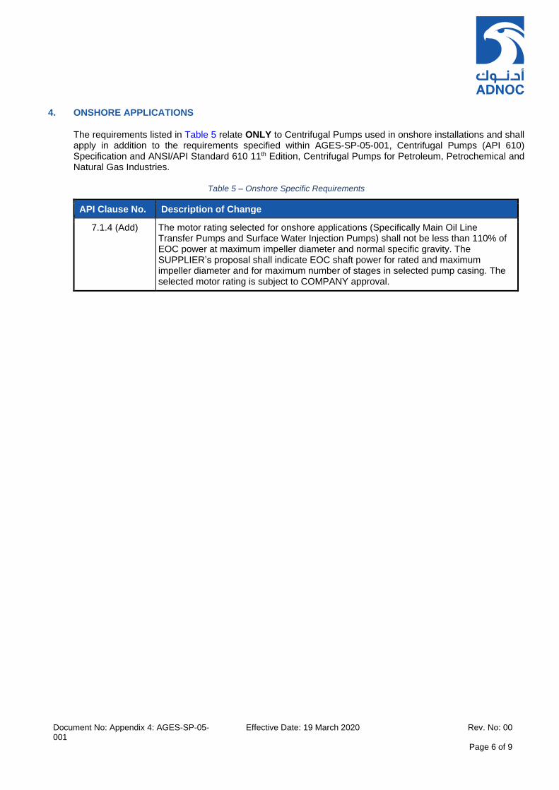
Document No: Appendix 4: AGES-SP-05-001
Effective Date: 19 March 2020 Rev. No: 00
Page 6 of 9
4. ONSHORE APPLICATIONS
The requirements listed in Table 5 relate ONLY to Centrifugal Pumps used in onshore installations and shall apply in addition to the requirements specified within AGES-SP-05-001, Centrifugal Pumps (API 610) Specification and ANSI/API Standard 610 11th Edition, Centrifugal Pumps for Petroleum, Petrochemical and Natural Gas Industries.
Table 5 – Onshore Specific Requirements
API Clause No. Description of Change
7.1.4 (Add) The motor rating selected for onshore applications (Specifically Main Oil Line Transfer Pumps and Surface Water Injection Pumps) shall not be less than 110% of EOC power at maximum impeller diameter and normal specific gravity. The SUPPLIER’s proposal shall indicate EOC shaft power for rated and maximum impeller diameter and for maximum number of stages in selected pump casing. The selected motor rating is subject to COMPANY approval.

Document No: Appendix 4: AGES-SP-05-001
Effective Date: 19 March 2020 Rev. No: 00
Page 7 of 9
5. REFINERY APPLICATIONS
The requirements listed in Table 6 relate ONLY to Centrifugal Pumps used in refinery installations and shall apply in addition to the requirements specified within AGES-SP-05-001, Centrifugal Pumps (API 610) Specification and ANSI/API Standard 610 11th Edition, Centrifugal Pumps for Petroleum, Petrochemical and Natural Gas Industries.
Table 6 – Refinery Specific Requirements
API Clause No. Description of Change
6.10.2.7.6 (New) For multiple horizontal pumps with anti-friction bearings and where pumps are located in the same vicinity, the bearings shall be equipped for purge oil mist lubrication, as follows:- a. One DN 6 (1/4 NPT) minimum hole in the top of the bearing housing located in the cavity between the thrust bearings and the radial bearing. This connection shall be marked, “oil mist vent”. b. One DN 10 (3/8 NPT) minimum hole in the bottom of the bearing housing located in the cavity between the thrust bearings and the radial bearing. This connection shall be marked, "oil mist drain”.
c. Two DN 6 (1/4 NPT) oil mist inlet holes located in the bearing housing or bearing end caps in the space between the bearing and the end cap closures. One connection shall be for thrust bearings and one for the radial bearing. Each connection shall be marked, “oil mist in”. For further details, refer to COMPANY business unit standard for Oil Mist Lubrication.
6.10.2.7.7 (New) For multiple vertical pumps with anti-friction bearings and where pumps are located in the same vicinity, the bearings shall be equipped for purge oil mist lubrication, as follows:- a. Two DN 6 (1/4 NPT) minimum holes, π radian (180 degree) apart in the bearing housing, located in the cavity between the thrust bearings and the radial bearing. Each connection shall be marked, “oil mist vent”. b. Two DN 6 (1/4 NPT) minimum holes, π radian (180 degree) apart in the bearing housing or bearing end cap for the space between the thrust bearings and end closure. These connections shall be marked, “oil mist in”. c. Two DN 6 (1/4 NPT) (DN 10 [3/8 NPT] preferred) minimum holes, π radian (180 degree) apart in the bearing housing or bearing end cap for the space between the radial bearing and end closure marked, “oil mist drain”. For further details, refer to COMPANY business unit standard for Oil Mist Lubrication.
6.10.2.7.8 (New) For multiple between bearings pumps with rolling element bearings and where pumps are located in the same vicinity, the bearings shall be equipped for purge oil mist lubrication, as follows:- a. Each bearing housing shall have a DN 6 (1/4 NPT) minimum hole in the top of the housing or bearing end cap into the space between the bearing and housing closure. These connections shall be marked, “oil mist in”. This connection shall not be in the same cavity as the bearing housing drain hole. b. Each bearing housing shall have a DN 6 (1/4 NPT) minimum hole in the top of the housing or bearing end cap in the space on the opposite side of the bearing from the oil mist inlet. These connections shall be marked, “oil mist vent”. c. Each bearing housing shall have a DN 10 (3/8 NPT) minimum hole in the bottom of the housing into the same cavity as the oil mist vent hole and on the opposite side
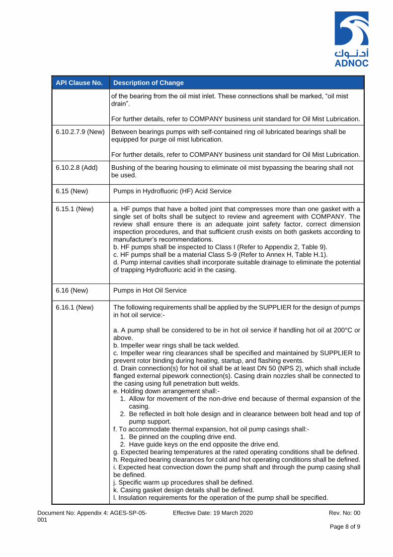
Document No: Appendix 4: AGES-SP-05-001
Effective Date: 19 March 2020 Rev. No: 00
Page 8 of 9
API Clause No. Description of Change
of the bearing from the oil mist inlet. These connections shall be marked, “oil mist drain”. For further details, refer to COMPANY business unit standard for Oil Mist Lubrication.
6.10.2.7.9 (New) Between bearings pumps with self-contained ring oil lubricated bearings shall be equipped for purge oil mist lubrication. For further details, refer to COMPANY business unit standard for Oil Mist Lubrication.
6.10.2.8 (Add) Bushing of the bearing housing to eliminate oil mist bypassing the bearing shall not be used.
6.15 (New) Pumps in Hydrofluoric (HF) Acid Service
6.15.1 (New) a. HF pumps that have a bolted joint that compresses more than one gasket with a single set of bolts shall be subject to review and agreement with COMPANY. The review shall ensure there is an adequate joint safety factor, correct dimension inspection procedures, and that sufficient crush exists on both gaskets according to manufacturer’s recommendations. b. HF pumps shall be inspected to Class I (Refer to Appendix 2, Table 9). c. HF pumps shall be a material Class S-9 (Refer to Annex H, Table H.1). d. Pump internal cavities shall incorporate suitable drainage to eliminate the potential of trapping Hydrofluoric acid in the casing.
6.16 (New) Pumps in Hot Oil Service
6.16.1 (New) The following requirements shall be applied by the SUPPLIER for the design of pumps in hot oil service:- a. A pump shall be considered to be in hot oil service if handling hot oil at 200°C or above. b. Impeller wear rings shall be tack welded. c. Impeller wear ring clearances shall be specified and maintained by SUPPLIER to prevent rotor binding during heating, startup, and flashing events. d. Drain connection(s) for hot oil shall be at least DN 50 (NPS 2), which shall include flanged external pipework connection(s). Casing drain nozzles shall be connected to the casing using full penetration butt welds. e. Holding down arrangement shall:-
1. Allow for movement of the non-drive end because of thermal expansion of the casing.
2. Be reflected in bolt hole design and in clearance between bolt head and top of pump support.
f. To accommodate thermal expansion, hot oil pump casings shall:- 1. Be pinned on the coupling drive end. 2. Have guide keys on the end opposite the drive end.
g. Expected bearing temperatures at the rated operating conditions shall be defined. h. Required bearing clearances for cold and hot operating conditions shall be defined. i. Expected heat convection down the pump shaft and through the pump casing shall be defined. j. Specific warm up procedures shall be defined. k. Casing gasket design details shall be defined. l. Insulation requirements for the operation of the pump shall be specified.

Document No: Appendix 4: AGES-SP-05-001
Effective Date: 19 March 2020 Rev. No: 00
Page 9 of 9
API Clause No. Description of Change
m. Hot oil pumps shall have a coupling spacer of at least 300 mm. n. Cold alignment settings shall be specified together with the assumptions used in arriving at these settings. o. If testing does not allow using contract seals, test seals shall use contract gland. p. Torque values with the required high temperature thread lubricant shall be specified. Oil shall not be used.

INSTRUMENTATION AND CONDITION MONITORING REQUIREMENTS
FOR
CENTRIFUGAL PUMPS (API 610) SPECIFICATION
Appendix 5 – AGES-SP-05-001
THE CONTENTS OF THIS DOCUMENT ARE PROPRIETARY AND CONFIDENTIAL
Document No: Appendix 5: AGES-SP-05-001 Effective Date: 19 March 2020 Rev. No: 00 Page 2 of 7
TABLE OF CONTENTS
1. SCOPE ............................................................................................................................................................ 3
2. NORMATIVE REFERENCES .......................................................................................................................... 3
3. LUBRICATION SYSTEM REQUIREMENTS .................................................................................................. 3
4. ALARM/SHUTDOWN REQUIREMENTS FOR PUMPS ................................................................................. 4
5. INSTRUMENTATION REQUIREMENTS FOR SELECTED BEARING ARRANGEMENTS .......................... 5
LIST OF TABLES
Table 1 – Alarm & Shutdown Requirements for Centrifugal Pumps ....................................................................... 4 Table 2 – Bearing Lubrication and Condition Monitoring Requirements ................................................................. 5
Document No: Appendix 5: AGES-SP-05-001 Effective Date: 19 March 2020 Rev. No: 00
Page 3 of 7
1. SCOPE
This Appendix contains minimum design requirements which should be taken into account regarding Machine Monitoring System (MMS). These requirements are applicable in conjunction with the requirements which have been specified in COMPANY specification DGS 1511 062, Machine Monitoring System.
All Rotating equipment designed under current COMPANY Standard shall be supplied with safeguarding SHUTDOWN functions to preclude serious failures resulting in potential hazards to personnel or the environment.
The minimum requirements for alarms and shutdowns are specified within Table 1. The requirements for condition monitoring instrumentation are specified within Table 2. This shall take precedence over the requirements specified within ANSI/API Standard 610 11th Edition Centrifugal Pumps for Petroleum, Petrochemical and Natural Gas Industries; AGES-SP-05-001, Centrifugal Pumps (API 610) Specification and Appendix 1, ‘General Technical and Contractual Requirements for Rotating Equipment’.
2. NORMATIVE REFERENCES
References used throughout this appendix are listed within AGES-SP-05-001, Centrifugal Pumps (API 610) Specification, Appendix 1, ‘General Technical and Contractual Requirements for Rotating Equipment’ and Appendix 4, ‘Cross References’. For dated references, only the edition cited applies. For undated references, the latest edition of the referenced document (including any amendments) applies.
3. LUBRICATION SYSTEM REQUIREMENTS
For details of permitted options for pump ‘LUBRICATION’ referred to in Table 2, refer to Appendix 6, ‘Lubrication System Design Requirements.
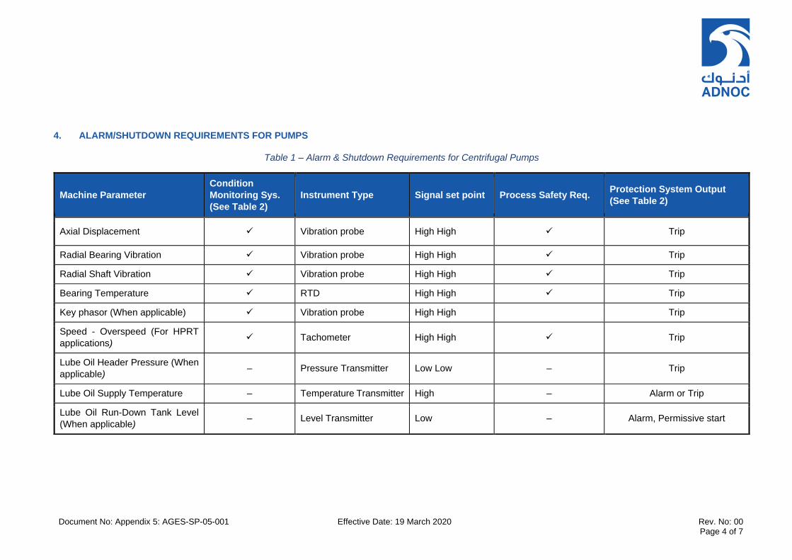
Document No: Appendix 5: AGES-SP-05-001 Effective Date: 19 March 2020 Rev. No: 00 Page 4 of 7
4. ALARM/SHUTDOWN REQUIREMENTS FOR PUMPS
Table 1 – Alarm & Shutdown Requirements for Centrifugal Pumps
Machine Parameter
Condition
Monitoring Sys.
(See Table 2)
Instrument Type Signal set point Process Safety Req. Protection System Output
(See Table 2)
Axial Displacement Vibration probe High High Trip
Radial Bearing Vibration Vibration probe High High Trip
Radial Shaft Vibration Vibration probe High High Trip
Bearing Temperature RTD High High Trip
Key phasor (When applicable) Vibration probe High High Trip
Speed - Overspeed (For HPRT
applications) Tachometer High High Trip
Lube Oil Header Pressure (When
applicable) – Pressure Transmitter Low Low – Trip
Lube Oil Supply Temperature – Temperature Transmitter High – Alarm or Trip
Lube Oil Run-Down Tank Level
(When applicable) – Level Transmitter Low – Alarm, Permissive start

Document No: Appendix 5: AGES-SP-05-001 Effective Date: 19 March 2020 Rev. No: 00
Page 5 of 7
5. INSTRUMENTATION REQUIREMENTS FOR SELECTED BEARING ARRANGEMENTS
Table 2 – Bearing Lubrication and Condition Monitoring Requirements
Pump Type Driver Rating/Service
Bearing Arrangement (As noted by API 610)
Vibration Instrumentation (Note 12)
Temperature Instrumentation (Note 12)
Key Phasor (Note 6)
Lubrication
All pump types (Note 4)
<=499 kW and non-critical service
Radial :- Antifriction Thrust :- Antifriction
Future provision only. Future provision only. No Refer to Appendix 7, Options A or B (Note 1)
All pump types (Note 4)
100kW to 499kW and in process critical service and installed in RED zone (Note 11)
Radial :- Antifriction Thrust :- Antifriction
Trend master (Portable data collector) is used to monitor equipment vibration data by polling. Monitoring instruments shall be supplied with pump package, which will typically include accelerometers (X-Y) on bearing housing(s). Type of probes shall be agreed with COMPANY.
Thermal image (infrared detectors) shall be installed per bearing and wired to Junction box mounted at skid edge.
No Refer to Appendix 7, Option A or B (Note 1)
BB, VS and OH (Note 5)
500 kW to 1000kW. All services
Radial :- Antifriction Thrust :- Hydrodynamic
Radial Bearing Accelerometer to be installed on bearing housing. All sensors fitted to both radial and thrust bearings shall be configured within the MMS to trip the machine following combined 2oo4 voting logic. The MMS shall consider any one probe at fault as a vote to trip in combination with the above. Thrust Bearing Provide X, Y proximity probes for each radial bearing. All four probes fitted to both radial and thrust bearing shall be configured within the MMS to trip the machine following combined 2oo4 voting logic. The MMS logic shall consider any one probe at fault as a vote to trip in combination with the above. Axial Displacement Minimum 2, and if possible three (based on bearing size, space). Where 3 probes are fitted, HH trip shall be based on 2oo3 voting. Where 2 probes are fitted, HH trip shall be based on 2oo2 voting. The logic shall consider any one probe at fault as a vote to trip in combination with the above.
Radial Bearing Temperature monitoring is required only when recommended and mandated by SUPPLIER. In this event, Thermal image (infrared detectors) shall be installed per bearing and wired to Junction box mounted at skid edge. HH trip shall be based on 2oo2 voting logic when two sensors are fitted, or 2oo4 when four sensors are fitted and where trips are configured within the MMS (Note 2). Thrust Bearing Two (2) RTD's installed per bearing and wired to Junction box mounted at skid edge in accordance with API 670 (Note 2). HH trip shall be based on 2oo2 voting logic when two RTDs are fitted, or 2oo4 when four RTDs are fitted and where trips are configured within the MMS (Note 2). Casing Temperature Provide for NGL and sulphur Services. For others, when specified.
Yes (Notes 3, 7, 8, 9 &
10)
Refer to Appendix 7, Option B or C (Note 1)
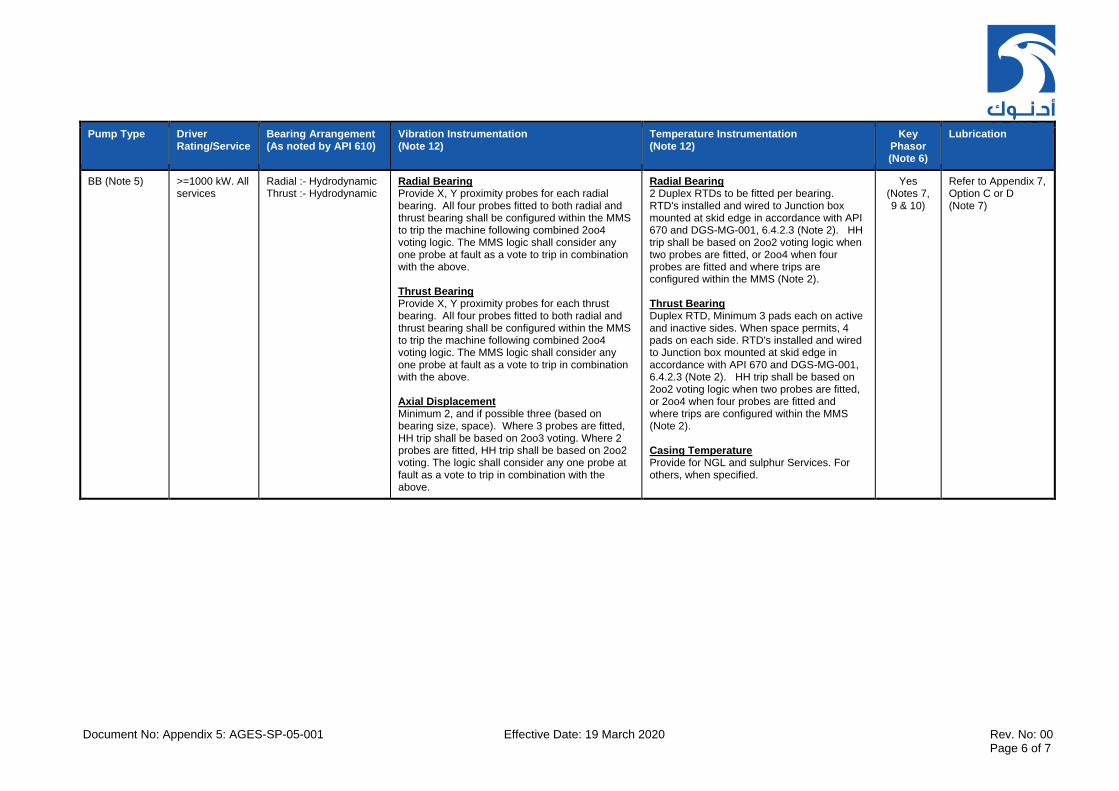
Document No: Appendix 5: AGES-SP-05-001 Effective Date: 19 March 2020 Rev. No: 00
Page 6 of 7
Pump Type Driver Rating/Service
Bearing Arrangement (As noted by API 610)
Vibration Instrumentation (Note 12)
Temperature Instrumentation (Note 12)
Key Phasor (Note 6)
Lubrication
BB (Note 5) >=1000 kW. All services
Radial :- Hydrodynamic Thrust :- Hydrodynamic
Radial Bearing Provide X, Y proximity probes for each radial bearing. All four probes fitted to both radial and thrust bearing shall be configured within the MMS to trip the machine following combined 2oo4 voting logic. The MMS logic shall consider any one probe at fault as a vote to trip in combination with the above. Thrust Bearing Provide X, Y proximity probes for each thrust bearing. All four probes fitted to both radial and thrust bearing shall be configured within the MMS to trip the machine following combined 2oo4 voting logic. The MMS logic shall consider any one probe at fault as a vote to trip in combination with the above. Axial Displacement Minimum 2, and if possible three (based on bearing size, space). Where 3 probes are fitted, HH trip shall be based on 2oo3 voting. Where 2 probes are fitted, HH trip shall be based on 2oo2 voting. The logic shall consider any one probe at fault as a vote to trip in combination with the above.
Radial Bearing 2 Duplex RTDs to be fitted per bearing. RTD's installed and wired to Junction box mounted at skid edge in accordance with API 670 and DGS-MG-001, 6.4.2.3 (Note 2). HH trip shall be based on 2oo2 voting logic when two probes are fitted, or 2oo4 when four probes are fitted and where trips are configured within the MMS (Note 2). Thrust Bearing Duplex RTD, Minimum 3 pads each on active and inactive sides. When space permits, 4 pads on each side. RTD's installed and wired to Junction box mounted at skid edge in accordance with API 670 and DGS-MG-001, 6.4.2.3 (Note 2). HH trip shall be based on 2oo2 voting logic when two probes are fitted, or 2oo4 when four probes are fitted and where trips are configured within the MMS (Note 2). Casing Temperature Provide for NGL and sulphur Services. For others, when specified.
Yes (Notes 7, 9 & 10)
Refer to Appendix 7, Option C or D (Note 7)

Document No: Appendix 5: AGES-SP-05-001 Effective Date: 19 March 2020 Rev. No: 00
Page 7 of 7
Pump Type Driver Rating/Service
Bearing Arrangement (As noted by API 610)
Vibration Instrumentation (Note 12)
Temperature Instrumentation (Note 12)
Key Phasor (Note 6)
Lubrication
Notes
1. To be suitable for connection to oil mist system when using anti-friction bearings and if specified for refinery service only. 2. All RTDs shall be Duplex type and shall be supplied with temperature transmitters, mounted in Junction Box on pump skid for connection to VMS/MMS. Trip logic shall use 2oo4 for radial
vibration (combining DE and NDE bearing), 2oo2 for temperature (on each side of bearing) and 2oo2/2oo3 for axial thrust. Alarm set points and associated voting logic to be identified on the applicable pump datasheets.
3. For VS1/VS2 pumps, reverse rotation ratchet (mechanical device) as well as reverse rotation sensors (2 nos. key phasors) shall be provided. For very high length VS6 pumps (>3m length) these instrument requirements shall be selected based on type of NRVs and pump suitability of operating in reverse for a significant duration.
4. For equipment located in areas where H2S risk is high (RED ZONES), irrespective of driver rating, continuous monitoring shall be implemented due to HSE issues. 5. 7.4.2.2 / 7.4.2.3 [ Add] If hydrodynamic bearings are provided, SUPPLIER shall supply, install and test these detectors. 6. 7.4.2.5 [New]: When utilising Variable Frequency Drives (VFD), a key phasor shall be provided for the driver and driven equipment which shall be configured on MMS and DCS. Local speed
indication is not required. 7. For equipment with hydrodynamic bearings, two radial vibration probes shall be mounted in each bearing housing, two axial position probes shall be mounted at the thrust end of each
machine, and a one-event–per-revolution probe shall be mounted in each machine. The SUPPLIER shall supply these detectors. The detectors and their mounting and calibration shall be supplied, installed, and tested in accordance with API 670.
8. If a speed increasing/decreasing gearbox transmission is used, key phasors for both high and low speed shafts shall be installed. 9. Casing vibration instruments (accelerometers) shall be supplied by SUPPLIER when requested in the equipment datasheets. Vibration monitors shall be part of MMS system and shall be
supplied by COMPANY. Vibration monitors shall be supplied for high energy pumps only where specified on the equipment datasheets. 10. For instrumentation requirements refer to COMPANY I&C standard that defines the Machine Monitoring System (MMS) requirements. The MMS will form a part of the Process Control
System (MMS) and Instrumentation Controls Package in accordance with COMPANY standard DGS 1511 062. BN3500 System 1 will be provided as MMS. 11. Definition of RED zone is according to hazardous area classification. Refer to COMPANY business unit HSE philosophy. 12. SUPPLIER to provide on skid wiring from all equipment-mounted instrumentation up to the skid edge mounted junction boxes. Interconnecting wiring from the skid edge mounted
junction boxes to the MMS shall be installed by the EPC CONTRACTOR. 13. In cases of dirty service with the risk of balance line choking, a pressure transmitter shall be installed in the balance line for all BB type of pumps for monitoring thrust balancing between
the stuffing boxes. EPC CONTRACTOR shall connect this to the DCS.
LUBRICATION SYSTEM DESIGN REQUIREMENTS
FOR
CENTRIFUGAL PUMPS (API 610) SPECIFICATION
Appendix 6 – AGES-SP-05-001
THE CONTENTS OF THIS DOCUMENT ARE PROPRIETARY AND CONFIDENTIAL CONFIDENTIAL CONTENTS OF THIS DOCUMENT ARE PROPRIETARY.

Document No: Appendix 6: AGES-SP-05-001
Effective Date: 19 March 2020 Rev. No: 00
Page 2 of 5
TABLE OF CONTENTS
1. SCOPE ........................................................................................................................................................ 3
2. NORMATIVE REFERENCES ...................................................................................................................... 3
3. LUBRICATION SYSTEM REQUIREMENTS .............................................................................................. 4

Document No: Appendix 6: AGES-SP-05-001
Effective Date: 19 March 2020 Rev. No: 00
Page 3 of 5
1. SCOPE
This Appendix contains the specific requirements for pump lubrication systems for different driver power ratings and should be read in conjunction with API 610 11th Edition, ANNEX B, COOLING WATER AND LUBRICATION SYSTEM SCHEMATICS. The requirements of Section 3 shall take precedence over the requirements specified within ANSI/API Standard 610 11th Edition, Centrifugal Pumps for Petroleum, Petrochemical and Natural Gas Industries; AGES-SP-05-001, Centrifugal Pumps (API 610) Specification and Appendix 1, ‘General Technical and Contractual Requirements for Rotating Equipment’.
2. NORMATIVE REFERENCES
References used throughout this appendix are listed within AGES-SP-05-001, Centrifugal Pumps (API 610) Specification, Appendix 1, ‘General Technical and Contractual Requirements for Rotating Equipment’. For dated references, only the edition cited applies. For undated references, the latest edition of the referenced document (including any amendments) applies.

Document No: Appendix 6: AGES-SP-05-001
Effective Date: 19 March 2020 Rev. No: 00
Page 4 of 5
3. LUBRICATION SYSTEM REQUIREMENTS
The SUPPLIER shall select a lubrication method for each pump in accordance with the following four types:-
A. OPTION A – FOR PUMPS WITH DRIVER RATING UP TO 100kW
Grease lubricated rolling element bearings may be used, subject to approval by COMPANY and where ambient temperature range is low (e.g. offshore application). In such cases, re-greasing or replacement intervals of the bearings shall be at least 50,000 running hours.
B. OPTION B - For pumps with driver rating up to 1000 kW
A self-contained bearing housing (flooded, ring oil with slinger etc.) shall be provided for each bearing. To allow for high ambient temperature conditions prevailing at sites, the SUPPLIER shall provide shaft mounted fans to enable direct air cooling. The suitability of shaft mounted fan shall be evaluated on a case by case basis. The use of cooling water or process fluid coils inside bearing housings is not acceptable unless approved by COMPANY.
C. OPTION C - For pumps with driver rating from 1000 kW up to 1500 kW
When the driver power rating is greater than or equal to 1000 kW and when hydrodynamic radial and thrust bearings are used, only pressurized lubrication systems shall be used to lubricate these bearings. In case of pumps equipped with “Tilted Pad Bearings” regardless of the driver power rating, forced feed lubrication shall be provided. The SUPPLIER shall supply his standard lube oil skid, which shall be mounted adjacent to the pump. The lube oil cooler shall be air cooled (where feasible) and shall be mounted on top of lube oil skid. Otherwise a water-cooled system may be used subject to availability of a clean and reliable supply of external cooling water.
The following additional requirements shall be applied for the design of the lube oil system:-
1. Oil pumps shall be of positive displacement type “triple screw” or “gear type” according to API 676 with separate PSV (not integral with the pump). Horizontal lube oil pumps shall be installed on LO skid, although vertical pumps may be installed where space constraints exist.
2. For sizing of air coolers, use a design ambient temperature of 54°C for onshore and island applications and 48°C for offshore applications; based on single fan operation and a peak ambient temperature of 58°C (with no design margin). At peak ambient temperature of 58°C, both fans shall operate to meet the cooling duty requirements.
3. Lube Oil coolers shall be of the “air cooled” type and include two (2) x 100% cooling fans, induced draft type. Forced draft fans may be used ONLY if the fan diameter is less than 750mm. Use of an OEM standard cooler instead of API 661 coolers for lube oil coolers up to 1000 kW pump driver rating is acceptable subject to COMPANY approval.
4. Lube Oil Coolers may be supplied with removable turbulators in stainless steel 316L. Marine grade aluminium extruded fins (394 fins/m) shall be provided on coolers. The complete lube oil cooler shall be constructed in stainless steel 316L (including tubes, headers, plugs etc.).
5. For water cooled systems, 2 x 100% shell and tube lube oil cooler/exchangers shall be used designed
according to TEMA C. A removable-bundle design is required for shell-and tube coolers with more than 0.46 m2 of tube surface area.
6. Each oil cooler shall maintain the lube oil supply temperature at or below 48 ºC for water cooled systems
and 68 ºC for air cooled systems.
7. ASME U-stamp or PED certified equipment is required for all heat exchangers (Lube Oil Coolers).
Document No: Appendix 6: AGES-SP-05-001
Effective Date: 19 March 2020 Rev. No: 00
Page 5 of 5
8. The following design margins shall be applied: The cooler shall be designed to accommodate 110% of
the maximum required oil flow defined as per API 614, cl 4.4.11b. In addition, the cooler shall be sized for the following design cases:-
a. 110% of the required heat transfer load and
b. 110% of the calculated heat exchange surface area
9. Oil filters shall have a continuous flow switch-over valve including a pressure equalization line. Duplex filters shall be provided with suitable range differential pressure gauges
10. All vent lines shall be equipped with an isolation valve.
11. The lube oil tank shall be sized for a minimum of 5 minutes circulation volume at the lube oil pump duty flowrate. If required, a rundown tank shall be provided and is preferred instead of a DC emergency pump. A startup interlock shall be provided to ensure minimum required lube oil temperature prior to start-up. Two (2 x 100%) duty/standby motor driven horizontal lube oil pumps shall be provided and an accumulator shall also be provided to ensure smooth pump changeover. For onshore applications only, a shaft driven main lube oil pump and motor driven auxiliary lube oil pump may be provided, subject to COMPANY approval and valid references being provided.
12. The complete lubricating oil system including, lube oil reservoir, oil coolers, filters and piping (except for lube oil pump) shall be supplied in Stainless Steel 316/316L construction as a minimum. Lube oil pump shall have CS casing with SS rotor. However, when using seawater as the cooling medium, oil coolers shall be constructed from Titanium or other suitable material to mitigate corrosive attack by seawater. All components of the lube oil system shall be externally painted in accordance with the relevant COMPANY business unit standard.
D. OPTION D - For pumps with driver rating 1500 kW and above
All pumps shall include a separate lube oil skid and lube oil cooler skid. The lube oil cooler skid shall be located outdoors and shall be designed in accordance with API 661 and applicable ADNOC Standards covering fans diameter, induced draft construction etc. Turbulators are not acceptable. The lube oil system for these applications shall follow API 614 as well satisfying the additional design requirements listed in items 1 through to 8 inclusive under OPTION C above.