intensity modulated radiation therapy in breast canceraroi.org/icro_pdf/5th icro gcri ahmedabad/dr...
TRANSCRIPT

Intensity Modulated Radiation Therapy in Breast Cancer
Dr Vijay Anand P ReddyDirector
Apollo Cancer Institute, Hyd
Dr Vijay Anand P ReddyDirector
Apollo Cancer Institute, Hyd

� Introduction
� Problems with Conventional RT
� Scope and Steps of IMRT in ca breast
� Advantages of IMRT in ca breast
� Conclusions� Off course ….thank u slide !
IMRT in Breast Cancer

Adjuvant RT in Breast CancerRationale Following Mastectomy
Meta-analysis of 18 Randomized Trials
In high-risk breast ca pts
Adjuvant RT improves survival by 8–10%
(p=0.004)
Whelan TJ, JCO 2000

Adjuvant RT in Breast CancerBreast Conserving Surgery
In high-risk patients, rate of local relapse reduced from 35% to 10%.
NSABP-06 Study, Fisher B, NEJM 1995
In early stage patients, rate of local relapse reduced from 24% to 8.5% in BCS
Liljegren G, JCO 1999

Conventional RT in Breast Cancer Components
� Tumour Volume– Whole Breast or Chestwall– Supraclavicular fossa (if >4 axillary LN+)– Axilla (if PNE+ or incomplete dissection)– IMC (not routinely)
� RT Fields– Whole Breast or Chestwall – Tangential Pair– Supraclavicular fossa + Axilla – Anterior Field + Post Boost
� Dose– Whole Breast or Chestwall – 45-50 Gy + Boost 10-15 Gy– Supraclavicular fossa + Axilla – 45-50 Gy

IMRT in Ca Breast…Rationale
� Adjuvant RT in breast cancer improves local control following mastectomy and BCS
� Breast RT in Early stage Breast Cancer is increasing as most pts are opting BCS
� Conventional RT carries significant acute and chronic toxicities
� IMRT has some advantages over conventional RT in Breast Cancer.
Conventional Adjuvant RT in Breast Ca
� Radiation dermatitis
� Radiation esophagitis
� Radiation pneumonitis
Acute Effects
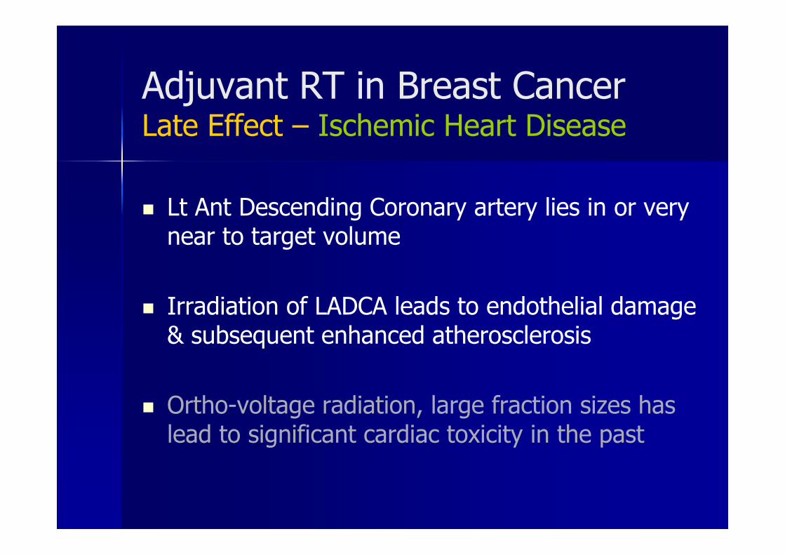
� Lt Ant Descending Coronary artery lies in or very near to target volume
� Irradiation of LADCA leads to endothelial damage & subsequent enhanced atherosclerosis
� Ortho-voltage radiation, large fraction sizes has lead to significant cardiac toxicity in the past
Adjuvant RT in Breast CancerLate Effect – Ischemic Heart Disease

� Conventional RT following mastectomy has been associated with an increased risk of late cardiac death, 10–15 yrs following treatment
� Fatal MI in left-sided breast ca was increased by 17% compared with right sided
SEER Database, Paszat LF, JCO 1998
Adjuvant RT in Breast CancerLate Effect – Ischaemic Heart Disease

� With modern technique also a small portion of myocardium recieves 50-95% of the total dose
� Myocardial perfusion scintigraphy study has shown hypoperfusion of irradiated myocardium (with modern techniques)
Gyenes G, IJROBP 1996
Adjuvant RT in Breast CancerLate Effect – Ischaemic Heart Disease

� Either surgery or RT alone is associated with only a low incidence of arm edema
� Combination of axillary RT with axillary dissection increases the risk of arm edema from 2–10% to 13–18%
Meek AG , Cancer 1998
Adjuvant RT in Breast CancerLate Effect – Lymphoedema

� Rare but serious complication in past as a result of match line overdosing to breast tangential fields
Johansson S , IJROBP 2001
� Can be avoided by – incorporation of a gap between beams– half beam blocking– couch tilt and – isocentric techniques
Adjuvant RT in Breast CancerLate Effect – Brachial Plexopathy

� Significant factors that affect cosmesis
– Large Breast size
– inferior tumor location
– large excision volume
– presence of post-operative complications
– Dose in-homogeneity within the breast
– use of a tumor bed boost.
EORTC study, Vreiling C, Radioth Oncol 2000
Adjuvant RT in Breast CancerLate Effect – Poor Cosmesis

� Cosmesis is affected by – Fibrosis of breast tissue
– Skin changes
Adjuvant RT in Breast CancerLate Effect – Poor Cosmesis

� Reducing dose inhomogeneity across the treatment volume
� Increasing Conformity of the dose
� Internal mammary node irradiation
� Simultaneous Integrated Boost to tumor cavity
� Possibly reduce morbidity
Scope of IMRT in Whole Breast RT

What is IMRT ?
Conformal Radiation Therapy with Non-uniform intensity distributionsgenerated via Inverse planningby a computer optimization process.
“ “Intensity of Radiation is modulated”
Intensity Modulated Radio Therapy

3D-Conformal Radiation Therapy
3D-CRT
• Radiation intensity is uniform within each beam
• Modulation conferred only by wedges.

How does I M R T works
Each field is subdivided into numerous “beamlets”
whose intensities are individually modulated
to achieve a nonuniform dose contribution from each field.
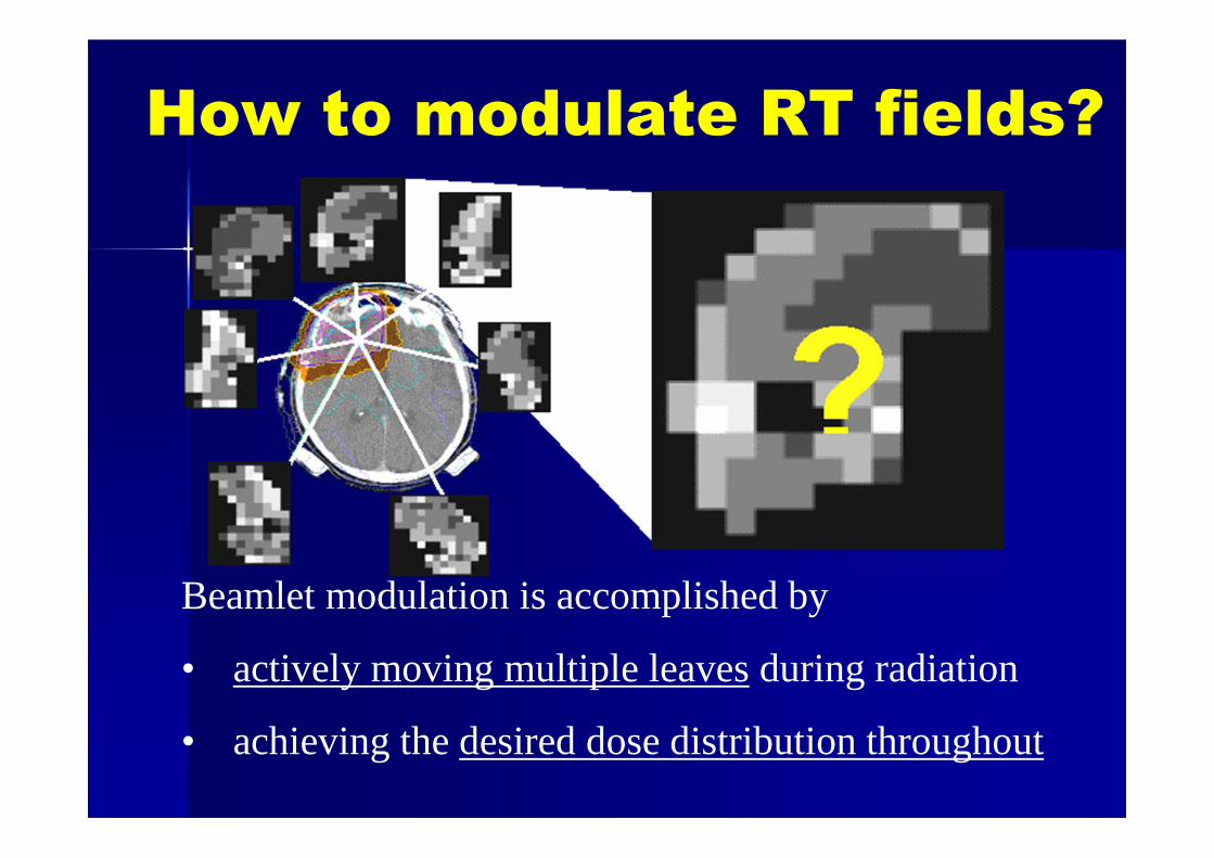
Beamlet modulation is accomplished by
• actively moving multiple leaves during radiation
• achieving the desired dose distribution throughout
How to modulate RT fields?

How does I M R T work
� 10 x 10 cm port is divided into 1 cm2 beamlets
� There are now 10+2 beamsin the port
� Each can have an intensityweight of 0 – 100%
� Then we have 10+200
possibilities� If we use 5 ports we have
10+1000possibilities

Inverse Planning
� We need to optimize Beam location, energy, modality
� High speed computer tests all the possibilities of a human decision for a best possible solution
� The mathematical process of defining a solution is known as “Inverse planning”

Computer Optimization
� Inverse Planning: The user specifies the goals, the computer then adjusts the beam parameters to achieve the desired outcome.
� Forward Planning:The beam geometry i.e beam angle, shape, modifier, weights etc. is first defined, followed by calculation of the 3D dose distribution.

IMRT
Primary advantage of this technology
• Treating target volumes adjacent to critical or sensitive normal tissues
• Delivery of therapeutic radiation doses to target
• Minimizing normal tissue toxicity.
IMRT Delivery techniques..

I M R T delivery techniques
1. Slit MLC:
• Narrow rectangular slit MLC
• Rotates in an arc around the patient
• Treats a target vol with multiple thin slices.
2. Tomotherapy:
• Actively modulated narrow slit beams
as the gantry and MLC rotate and also
pt moves through gantry ring on a couch.

I M R T delivery techniquesStandard MLC:
Beams can be delivered via multiple fixed gantry positions with a standard MLC
3. ‘Step and shoot’
• Delivers Sequential subfields with
• Individualized intensity distributions from each gantry position
• Radiation beam off between subfields.
4. Dynamic mode
• MLCs move while radiation beam is on

I M R T delivery techniques
5. Intensity modulated Arc therapy(IMAT) combining rotational arcs with dynamic multileaf collimation.
6. Fully dynamic systems MLC, gantry, and treatment couch all move independently at some point during beam delivery

IMRT / IGRT
Tomotherapy

Steps of IMRT in Whole Breast RT Immobilization
Breast Board (Inclined or Flat)
Position arms above head
Confirm patient position (Straight) on fluoroscopy

Steps of IMRT in Breast Initial Simulation
Place radio-opaque wire around breast to define clinical borders
Thermoplastic mask
Marks made anterior and each side on chest

Steps of IMRT in Whole Breast RT Planning CT Scan
Superiorly from the chin to inferiorly 5 cm below breast
Acquire 5 mm cuts

Steps of IMRT in Whole Breast RTTarget Volume Definition
Define
Lumpectomy
Cavity

Steps of IMRT in Whole Breast RTTarget Volume Definition
� Inter-physician variation in PTV delineation after BCS is high
� No clear definition in the literatureabout a clinically acceptable variability in breast delineation using CT image

Steps of IMRT in Whole Breast RTTarget Volume Definition – PTV
William Beaumont definition in NSABP B-39 trial
PTV is defined as
� the tissue within the conventional tangential fields
� excluding lung, heart and liver
� minus a 5 mm margin from the beam edges and skin surface

Steps of IMRT in Whole Breast RTTarget Volume Definition
� The superior, inferior, and medial-lateral borders of PTV are according to the conventional tangent beams.

Steps of IMRT in Whole Breast RTOrgans at Risk (OAR) Definition
� Skin surface
� Lungs
� HeartAll myocardium from apex to the
infundibulum of the right ventricle, the right atrium, and auricle

Steps of IMRT in Whole Breast RTTreatment Planning – 1st Step Conventional
� Two tangential beamsare chosen with appropriate angle to align the radio-opaque markers
� Posterior border of the lateral and medial fields are coplanar, so as to prevent extra dose to the lung due to the divergence of the beams.

Steps of IMRT in Whole Breast RTTreatment Planning – 1st Step Conventional
� Beam depth, gantry angle, and collimator angle are adjusted at the computer work station as need to avoid unnecessary normal tissue irradiation (e.g., heart, lung, contra lateral breast) and to ensure full coverage of the breast and lumpectomy cavity with a “sufficient” margin.
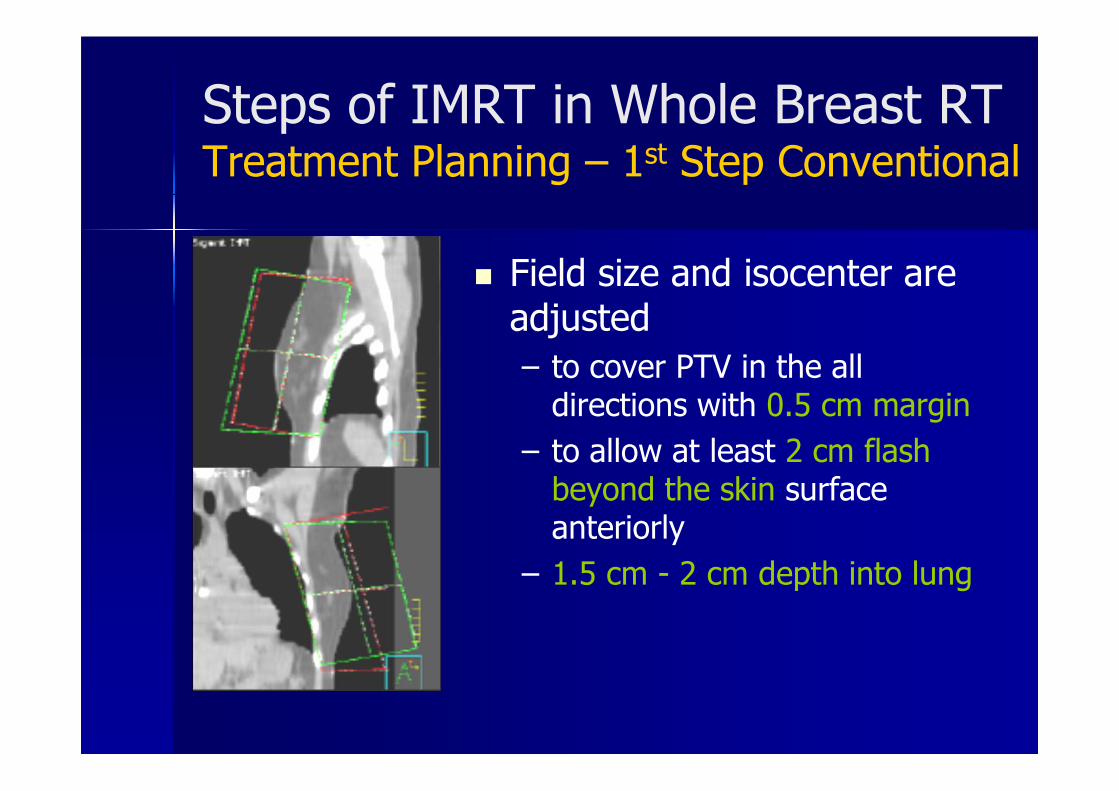
Steps of IMRT in Whole Breast RTTreatment Planning – 1st Step Conventional
� Field size and isocenter are adjusted
– to cover PTV in the all directions with 0.5 cm margin
– to allow at least 2 cm flash beyond the skin surface anteriorly
– 1.5 cm - 2 cm depth into lung

Steps of IMRT in Whole Breast RTOrgans at Risk (OAR) Definition
Contour the
tangential beam
edge to create a
“Dummy ROI”

Steps of IMRT in Whole Breast RTRegions of Interest are defined

Steps of IMRT in Whole Breast RT Treatment Planning Methods
� Inverse Planning
� Forawrd planning
� BEV Contouring
� Plane Compensation
� Minimization of Dose Variation; Equalization of Maximum Dose

Steps of IMRT in Whole Breast RTTreatment Planning – Forward IMRT
� The beam parameters for the intensity modulated tangential fields were the same as those used for the conventional field plan.
� Dose distribution is calculated for equally weighted, open tangential fields (i.e., no blocks, no wedges)

Steps of IMRT in Whole Breast RTTreatment Planning – Forward IMRT
� Use the beam’s eye view of the projected isodoses for the tangential fields to create multiple static fields to shield the area of higher dose (hot spot)

Steps of IMRT in Whole Breast RTTreatment Planning – Forward IMRT
� The MLCs are moved manually to cover the hot spots
� The MLC field is used to deliver approximately 6-10% of the total dose
� Beam weighting is adjusted until the most homogenous dose distribution is achieved

Steps of IMRT in Whole Breast RTTreatment Planning – Forward IMRT

Forward IMRT planning
Steps of IMRT in Whole Breast RTTreatment Planning – Inverse IMRT
� The gantry angles for the intensity-modulated tangential fields were the same as those used for the conventional technique.
� Beam configuration and dose volume constraint are given to the computer.
� Computer will Optimize the dose distribution
� A separate sequencer (leaf motion calculator) is used to convert the optimal fluencies profiles to suitable sliding windows MLC movement

Steps of IMRT in Whole Breast RTTreatment Planning – Inverse IMRT
� The gantry angles for the intensity-modulated tangential fields were the same as those used for the conventional technique.
� Beam configuration and dose volume constraint are given to the computer.
� Computer will Optimize the dose distribution

Steps of IMRT in Whole Breast RT Plan Evaluation - PTV
� Prescription dose 45- 50 Gy in 25-28 fr over 5 weeks.
� Prescribed at the isodose line which encompasses at least 95% of the PTV
� < 5% of PTV should receive > 105% of prescribed dose
� < 1% of PTV should receive < 95% of its prescribed dose
� < 1% or 1 cc of the tissue outside the PTV should receive > 110% of the prescribed dose

Steps of IMRT in Whole Breast RT Plan Evaluation - Critical organs
� Heart V30Gy < 3% (Heart volume receiving 30Gy should be <3%)
� Ipsilateral lung V20Gy < 10%(Ipsilateral lung volume receiving 20Gy should be <10%)
� Contralateral lung V20Gy < 5%(Contralateral lung volume receiving 20Gy should be <5%)
� Contralateral breast V2Gy < 50%(Contralateral Breast volume receiving 2Gy should be <50%)

Advantages of IMRT.. Reducing dose inhomogeneity
Conventional RTMedial and lateral aspects of the breast may be exposed to higher doses of radiation due to lower attenuation of which is always included in the treatment volume

Advantages of IMRT …Reducing dose inhomogeneity
Conventional RTSuperior and inferior part of breast shows 15-20% dose in-homogenity due to continuous change in shape of the breast in multiple planes

IMRT in Whole Breast RT Advantage - Reducing dose inhomogeneity
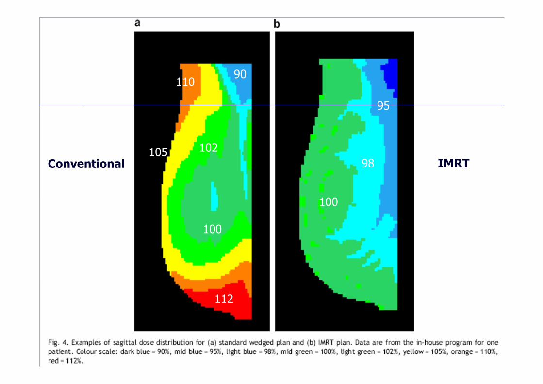
Conventional IMRT
112
110
105 102
100
90
100
98
95

IMRT Ca Lt Breast

� 300 patients data
� Application of IMRT to the tangential field reduces high dose regions in both volume and dose level
� IMRT reduced the volume receiving a dose greater than 105% by a mean of 10.7% (p= <0.001)
Donovan EM, Br J Rad 2002
Scope of IMRT in Whole Breast RT Advantage - Reducing dose inhomogeneity

� 110 patients
� The use of IMRT technique for breast is an efficient and effective method for achieving uniform dose throughout the breast.
� It is dosimetrically superior to the treatment techniques that employ only wedges.
Kestin LL, IJROBOP 2000
Scope of IMRT in Whole Breast RT Advantage - Reducing dose inhomogeneity

Wide Tangent Direct IMC Field
IMRT

IMRT IMC node

IMRT IMC node
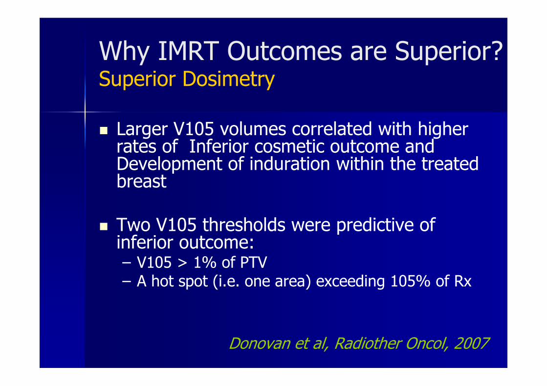
Why IMRT Outcomes are Superior?Superior Dosimetry
� Larger V105 volumes correlated with higher rates of Inferior cosmetic outcome and Development of induration within the treated breast
� Two V105 thresholds were predictive of inferior outcome:– V105 > 1% of PTV– A hot spot (i.e. one area) exceeding 105% of Rx
Donovan et al, Radiother Oncol, 2007

IMRT : Simultaneous Boost Lumpectomy site

Proven Benefits IMRT in Breast RT Decrease in moist desquamation
IMRT significantly decreased the risk ofdeveloping moist desquamation during RT(from 48% to 31%; p = 0.002).
Pignol et al, JCO, 2008

Proven Benefits of IMRT in ca breast
Preserved Cosmesis
IMRT significantly demonstrates no changein appearance 5 years after RT (from 42% to60%; p = 0.008).
IMRT significantly decreased the likelihoodthat the irradiated breast developed palpableinduration 5 years after RT (from 61% to 37%;p < 0.001).
Donovan et al, Radiother Oncol, 2007

Does IMRT spare Heart?
� With tangent fields IMRT , you cannot spare the heart
� You can’t use non-tangential fields because of an increase in scattered dose to lung and contralateral Breast

Multible beam technique…


What are the ideal beams for IMRT?Tangentials
� Tangential Beams with co-planar deep border are ideal due to less scatters dose to opposite breast
� Using multiple (4 or 6) non-coplanar beams increases scatter dose, esp. to the opposite breast and ipsilateral lung.
Landau, Radiother Oncol, 2007

� Dose homogeneity within the breast was improved with the two- and four-field IMRT techniques.
� The four-field tangential arrangement was found to be the best of the IMRT techniques considered here in terms of cardiac avoidance and gave improved sparing
What are the ideal beams for IMRT?Tangentials

How to spare the heart ?Deep Breath Hold Technique
� Patient is treated while holding breath
� Inspiration increases the separation between the heart and the left breast/chest wall
� Allows tangents to be used (which minimizes scattered dose)
� Requires special monitoring
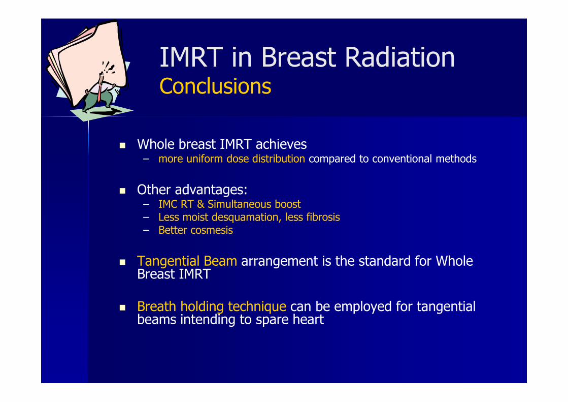
IMRT in Breast RadiationConclusions
� Whole breast IMRT achieves– more uniform dose distribution compared to conventional methods
� Other advantages: – IMC RT & Simultaneous boost– Less moist desquamation, less fibrosis– Better cosmesis
� Tangential Beam arrangement is the standard for Whole Breast IMRT
� Breath holding technique can be employed for tangential beams intending to spare heart

Thank You!
Dr. Vijay Anand Reddy PMD, DNB (RO), Med Onc (ESMO), FUICC(UK), FNDM(USA), FUICC(AUS)
Director
Apollo Cancer Hospital, Hyd