intelligent multi-agent system for building heat
TRANSCRIPT

Article
Intelligent Multi-Agent System for Building Heat Distribution Control with Combined Gas Boilers and Ground SourceHeat Pump
Mokhtar, Maizura, Stables, Matthew, Liu, Xiongwei and Howe, Joe
Available at http://clok.uclan.ac.uk/7827/
Mokhtar, Maizura ORCID: 0000-0003-0460-3696, Stables, Matthew ORCID: 0000-0002-9971-9458, Liu, Xiongwei and Howe, Joe (2013) Intelligent Multi-Agent System for Building Heat Distribution Control with Combined Gas Boilers and Ground Source Heat Pump. Energy and Buildings, - (-). ---. ISSN 03787788
It is advisable to refer to the publisher’s version if you intend to cite from the work.http://dx.doi.org/10.1016/j.enbuild.2013.03.045
For more information about UCLan’s research in this area go to http://www.uclan.ac.uk/researchgroups/ and search for <name of research Group>.
For information about Research generally at UCLan please go to http://www.uclan.ac.uk/research/
All outputs in CLoK are protected by Intellectual Property Rights law, includingCopyright law. Copyright, IPR and Moral Rights for the works on this site are retainedby the individual authors and/or other copyright owners. Terms and conditions for useof this material are defined in the policies page.
CLoKCentral Lancashire online Knowledgewww.clok.uclan.ac.uk

Accepted Manuscript
Title: Intelligent Multi-Agent System for Building HeatDistribution Control with Combined Gas Boilers and GroundSource Heat Pump
Author: Maizura Mokhtar Matthew Stables Xiongwei Liu JoeHowe
PII: S0378-7788(13)00213-2DOI: http://dx.doi.org/doi:10.1016/j.enbuild.2013.03.045Reference: ENB 4233
To appear in: ENB
Received date: 9-10-2012Revised date: 16-3-2013Accepted date: 23-3-2013
Please cite this article as: Maizura Mokhtar, Matthew Stables, Xiongwei Liu, JoeHowe, Intelligent Multi-Agent System for Building Heat Distribution Control withCombined Gas Boilers and Ground Source Heat Pump, Energy & Buildings (2013),http://dx.doi.org/10.1016/j.enbuild.2013.03.045
This is a PDF file of an unedited manuscript that has been accepted for publication.As a service to our customers we are providing this early version of the manuscript.The manuscript will undergo copyediting, typesetting, and review of the resulting proofbefore it is published in its final form. Please note that during the production processerrors may be discovered which could affect the content, and all legal disclaimers thatapply to the journal pertain.

Page 1 of 16
Accep
ted
Man
uscr
ipt
Intelligent Multi-Agent System for Building Heat Distribution Controlwith Combined Gas Boilers and Ground Source Heat Pump
Maizura Mokhtara, Matthew Stablesa, Xiongwei Liub, Joe Howea
aSchool of Computing, Engineering and Physical Sciences, University of Central Lancashire,Preston, PR1 2HE, UK (email: {MMokhtar,MStables,JMHowe}@uclan.ac.uk)
bSustainable Engineering, University of Cumbria, UK (email: [email protected])
Abstract
Intelligent energy system refers to the use of intelligent control strategies with the energy system, which can help minimise energywaste and loss, optimise load control, increase and improve energy efficiency and/or maximise the benefits of renewable energy.Renewable energy and intelligent controls are interlinked and correlated with each other. Without intelligent controls, the fullbenefits of renewable energy technologies may not be achievable, specifically the Ground Source Heat Pump (GSHP) technologies.This was observed, especially by the University of Central Lancashire (UCLan) that had incorporated a GSHP to one of its building.The GSHP is under performing due to the inefficient controls implemented with the GSHP. This paper proposes an intelligent multi-agent building management system (MAS BMS) that aims to tackle this issue. Intelligence is provided by an ARTMAP, a type ofartificial neural network that provides incremental learning inspired by how human process memory. Simulation results show theproposed intelligent MAS BMS is able to maximise the use of the GSHP effectively by profiling, predicting and coordinating itsusage with other energy resources. The proposed method has performed better than the existing control strategies for the GSHP.
Keywords: Building management system, Multi-agent system, Artificial neural network, Intelligent energy management system.
1. Introduction
The need for intelligent energy system arises due to techno-logical innovations that has resulted in the increasing demandfor more energy to accommodate improving lifestyles. Thishas caused significant detrimental impact on the environment,specifically environmental changes.
To date, the major sources of energy for the UK are from non-renewable carbon-based fuels, with almost 77% of electricityproduced are from these sources [1]. High use of carbon-basedfuels leads to high CO2 gas emission, contributing to globalwarming [1], [2]. Reducing the use of carbon-based fuels andsubstituting them with renewable energy sources may help re-duce the CO2 gas emission [1], [2].
Intelligent systems are autonomous (or semi-autonomous)systems that have the ability to monitor their system behaviourand provide the necessary controls to increase efficiency. Theuse of intelligent controls may help optimise the use of renew-able energy by (i) minimising energy waste and loss, (ii) opti-mising load control, and (iii) increasing and improving energyefficiency. This, in turn can maximise the use and benefits ofrenewable energy, which can help reduce the cost of energyusage as well as the CO2 gas emission and its effect to the envi-ronment.
Intelligent controllers are required to ensure efficient renew-able energy usage, particularly when the building incorporatesslow response renewable technologies, such as the GroundSource Heat Pumps (GSHP) [3]–[6]. Furthermore, a number ofreports [7] - [10] have indicated that the reductions in predicted
efficiency and the under performance of such technologies aredue to unsuitable control mechanisms, i.e. non-intelligent con-trols strategies.
The University of Central Lancashire (UCLan) has its ownexample. The Samuel Lindow Building (SLB) at UCLan West-Lakes Campus in Cumbria is installed with a GSHP that oper-ates in addition to the conventional gas central heating system[11]. Despite this, the controller used to manage this renew-able energy is not intelligent. Investigations of the output fromthe GSHP at UCLan’s SLB indicate that the GSHP is underperforming. This may have resulted from the inefficient non-intelligent control strategies of the existing building manage-ment system (BMS).
The existing BMS uses a Multi Agent System (MAS) ap-proach with the rule-based mechanism. The rule-based mecha-nism lacks adaptiveness and flexibility of controls, which mayhave resulted in the under performing of the GSHP. This paperproposes a new MAS with a new intelligent and adaptive con-trol strategies to manage the different heat sources in SLB, in-cluding the GSHP. The new MAS incorporates a computationalintelligence algorithm (artificial neural network) that aims toimprove and maximise the use of the GSHP in providing heatfor the building. This is achieved by profiling, predicting andcoordinating its usage with other energy sources, and in accor-dance to the heat demand required (also profiled and predicted).
The paper introduces a MAS BMS with ARTMAP, a type ofANN that adds intelligence to the MAS. The paper is dividedinto eight sections. Section 2 provides a brief summary of theexisting MAS used for BMS as well as a brief introduction to
Preprint submitted to Energy and Building April 1, 2013

Page 2 of 16
Accep
ted
Man
uscr
ipt
the proposed ARTMAP. Section 3 describes the UCLan West-Lakes Samuel Lindow Building (SLB). Section 4 describes theexisting MAS BMS that is currently in place and in use to pro-vide heat to the SLB. Section 5 presents the method proposedto help maximise the use of the GSHP for the SLB. Section 6presents and discusses the case studies used to test and anal-yse the proposed method presented in Section 5. Section 7 de-scribes the results of the case studies and Section 8 concludesthe paper.
2. Multi Agent System
Multi-agent system (MAS) consists of two or more agentsin an environment. Each agent has its own functions or goals,and interacts with each other in a peer-to-peer (decentralisedor distributive) manner so as to achieve its collective goalsor objectives. MAS is particularly suitable for the distribu-tive control tasks in a building environment (MAS BMS) be-cause of their distinctive advantages, such as modular struc-ture, openness, self-capacities, self-organisation and high-leveltransparency [14] - [15]. For example, each room in the build-ing will have its own individual room temperature and thermalcomfort control that is independent of the boiler control sys-tem. Therefore, the room requires its own agent and the boilersystem has another. Mutual agreement and decision makingare achieved through communication between the agents in thebuilding.
MAS alone, however, has low level on-line learning andadaptation capabilities. Recently, artificial neural network(ANN) and/or fuzzy techniques are incorporated to the agentsof the MAS, with the goal of incorporating online learning andadaptation capabilities to the MAS and other performance im-provements [15] - [17]. The examples of such incorporationare:
1. Fuzzy MAS BMS: Fuzzy logic is suitable for BMS becausethe objective of thermal comfort management may be re-ferred to as the state of mind or psycho-synthesis of theoccupants in a building environment that expresses satis-faction with the temperature in the building. This is fun-damentally a fuzzy concept, which differs from people topeople, and is dependent on the type of activities they areengaged in [18] - [22].
2. ANN MAS BMS: Liang [23] has developed a back-propagation ANN that is used to maintain the thermalcomfort level within a desired range. However, due to theslow convergence of back-propagation, the controller maynot be a feasible solution for large building environment.
3. Neuro-fuzzy Thermal Comfort Management: Neuro-fuzzysystems combine ANN and fuzzy techniques. Yamahaet. al. [24] has developed a neuro-fuzzy BMS to pre-dict weather parameters and the number of occupants in abuilding. This predictive information are then used to pro-file the energy flow for the building in order to minimiseenergy consumption and to maintain thermal comfort at anacceptable level.
2.1. Proposed Algorithm: ARTMAP
This paper presents the use of ARTMAP to add intelligenceand online learning to the MAS BMS. ARTMAP, which wasdeveloped by Carpenter et. al. [27], is a supervised artificialneural network (ANN) algorithm inspired by how human pro-cess memory, and is able to learn new information without nec-essarily forgetting previously learned information [27], [28].ARTMAP deals with the stability and plasticity issues by com-bining two adaptive resonance theory (ART) networks, i.e. ARTa and ART b, as illustrated in Figure 1, which have the ability toestablish memory (the input-to-output correlations) within thetwo networks. A memory is created through the interconnectionthat transfers short term memory (STM) to and from long termmemory (LTM) within each ART network [27], [28]. ARTMAPperforms both prediction and classification, and is an ideal toolfor online learning and adaptation of an agent.
ARTMAP works by classifying and categorising the inputspresented to the network at ART a according to the desired cat-egories (supervisory inputs) presented at ART b [27], [28]. Dur-ing supervised learning, ART a receives the inputs that neededto be classified, whilst ART b indicates how the provided inputsshould be classified. The two ARTs are linked by an associa-tive memory, as illustrated in Figure 1. The associative mem-ory consists of an associative map and a controller, called mapfield, that prevents category proliferations within ART a [27].
The associative map does not directly associate inputs pre-sented to ART a and ART b, but instead creates the associationbetween the category activation produced by ART a and ART b[27]. The map field uses a minimax learning rule that automati-cally links predictive success (the category activation producedby ART a) that matches the category activation produced byART b. The learning rule is executed on a trial-by-trial basis,by increasing the vigilance parameter of ART a (ρa) with theminimum amount needed to make the corrective predictive er-ror at ART b [27]. The smaller the ρa value, the bigger the sizeof the category. This process is called match tracking, whichsacrifices generalisation in order to ensure minimal predictiveerror [27]. If the predictive error persists, a new category willbe created within ART a, which correlates the new input pat-terns presented to ART a to the input (category) informationpresented to ART b.
This architecture helps ARTMAP learn new data without for-getting its previously learnt information, as well as providingthe ability to infer the adaptive output based on newly acquiredmemory [27], [28].
3. UCLan Samuel Lindow Building
UCLan Samuel Lindow Building (SLB) uses gas fired boilersand a Ground Source Heat Pump (GSHP) as heat sources for thebuilding. As indicated in Section 1, the SLB heat distributionis controlled by a rule-based multi agent building managementsystem (MAS BMS) that aims to maintain the temperature ofthe building zones at 23◦C ±2◦C.
The current MAS BMS splits the building into 4 zones, witheach zone controlled by an agent. The zones are:
2

Page 3 of 16
Accep
ted
Man
uscr
ipt
ART b
Associa+ve Memory
Supervisory Input (b)
-
-
- Orienting Subsystem
Gain control
STM F1
STM F2
ρ
LTM LTM
-
- +
+ reset
Inputs (a)
+
+
+ + Gain 1
Gain 2
Internal Regulation
Matching criterion: Vigilance parameter
Attentional Subsystem Search/ Orienting Subsystem
-
ART a
Outputs
Input Weight
Figure 1: ARTMAP structure [27], [28].
1. Reception Zone: located on the ground floor and includesa cafe/restaurant area. The Reception Zone is shown inFigure 2, which also includes the area labelled the Openarea zone.
2. BIU Zone: Business Incubation Unit (BIU) is also locatedon the ground floor and consists of one open work area andthree small offices. BIU is shown in Figure 2.
3. Ground Floor Zone: This is the remainder of ground floorarea and consists of a lecture theatre and various rooms onthe ground floor, as shown in Figure 2.
4. First Floor Zone: consists of offices including a computerroom, class rooms and a mezzanine/library floor.
The heat for Zones 2, 3 and 4 are provided by radiatorpanel(s) in each room in the zones, with the gas boilers pro-viding the heat to the radiators. The heat for Zone 1 is providedby:
1. Underfloor heating (UFH), with the heat provided by theGSHP.
2. Five radiator panels, with the heat provided by the boilers.
We are limiting our analysis of the MAS BMS and subse-quent application of the newly proposed MAS BMS controls toZone 1 only. Further information on other zones are describedin [17] and [25].
3.1. Reception ZoneThe Reception Zone (Zone 1) is divided into seven sub-
zones. Each sub-zone has a temperature sensor. Five out ofthe seven sub-zone temperature sensors monitor the sub-zonesheated by the radiator panels, one per each sub-zone. The UFHprovides heat to the remaining two sub-zones, with a tempera-ture sensor installed at each of the two sub-zones.
3.1.1. The Under Floor Heating System (UFH)The underfloor heating system or UFH is a sequence of nine
loops of 40mm plastic tubes arranged in parallel to cover theentire 165m2 floor space of the room. The tubes are set 150mmapart. The loops are arranged so that heating is applied evenlythroughout the room as warm water passes along the length ofthe pipe in each loop.
The heat (warm water) for the UFH heating system is pro-vided by the Visemann Vitocell 300-B 500l heat exchange ves-sel [12]. The exchange vessel uses two indirect coils to ex-change heat via the water in the tank. The maximum heat out-put from the vessel is 15kW, pumped at a rate of 0.39ls−1 by theUFH heating pump. Figure 6 (on page 7) shows the recordedwater temperature of the exchange vessel. Heat is supplied tothe exchange vessel from the Visemann Vitocell 300G GroundSource Heat Pump (GSHP) [13].
3.1.2. Ground Source Heat PumpThe GSHP works by pumping a fluid along pipes buried un-
derground. The heat that may be extracted from the groundis dependent on the temperature of the ground, the size of theevaporation chamber and the capability of the pump. Figure 3shows the relationship between the ground temperature and theheat that may be extracted (A), as well as the electrical powerused by the heat pump to perform the evaporation, compressionand condensing (C). The heat pump may be used for cooling,and this performance is shown by (B) in Figure 3. The perfor-mance of the heat pump depends on the temperature the fluid israised to.
The system installed in the SLB is set to maximum 55◦C (F),while better performance may be reached with lower tempera-tures 45◦C (E) and 35◦C (D). The maximum output from theGSHP is 29kW for heating the brine to 55◦C with very warm
3

Page 4 of 16
Accep
ted
Man
uscr
ipt
LectureTheater
Restaurant
CorridorCorridor Corridor
Kitch
en
Corridor
Mens'sToilet
Women'sToilet
DisableToilet
WetLab
BusinessIncubation
Unit(BIU)
BIU Office
BIUOffice
BIUOffice
ReceptionArea
(Underfloor heatingor UFH)
Front d
oor
Rece
ptio
nD
esk
Stairs
Stairs
Ground floor zone's rooms
BIU zone's rooms
Open area zone
UFH zone
Rem
ovab
le p
artitio
n
Figure 2: The schematic of the ground floor of UCLan Samuel Lindow Building.
ground temperature (> 15◦C), but closer to 24.8kW at a groundtemperature at ≈ 8◦C. The electrical power used to achieve thisis ≈ 7.6kW, giving a coefficient of performance (CoP) of 3.26.By comparison, the gas boilers may only be 85-92% efficient,therefore having far lower CoP values.
4. The Existing Multi Agent Building Management System(MAS BMS)
As described in Section 1, the existing building managementsystem (BMS) uses a multi-agent system (MAS) to manage itsheat distribution. The existing MAS BMS, illustrated in Figure4, consists of User Agents and Source Agents. A User Agent isresponsible for achieving and maintaining the desired temper-ature for each of its respective zone (Section 4.1). The SourceAgent is responsible for describing how best to provide heat forthe building (Section 4.2).
4.1. User AgentsIn the existing BMS, the User Agents are incorporated with
a set of rules (rule-based method) to ensure that the building ismaintained within the desired temperature. The rules are:
If ( zone temperature < desired temperature )Then open the hot water valve to the zone to allow the hotwater to flow to the radiators in the zone and the watertemperature in the radiators to increase to approximately(maximum of) 80◦C;
Else
Then close the hot water valve and the water temperature inthe radiators decreased and maintained at the decreasedtemperature until the zone temperature = ( desiredtemperature - 2◦C );
The hot water temperature to a zone decreases by mixing hotwater from the boilers with the return water from the radiatorsin the zone.
The desired temperatures of the zone are:
If ( during the weekdays )Then desired temperature ≈ 23◦C;
ElseThen desired temperature ≈ 10◦C;
4.2. Source AgentsThe Source Agent for the boiler system states that:
If during the weekdays and between 02:00 to 21:00hrThen the boilers are switched on andhot water temperature ≈ 80◦C;
ElseThen the boilers are switched off and the water temperaturefrom the boilers are cooled;
The Source Agent for the GSHP states that:
If ( zone temperature < desired temperature )Then the GSHP is switched on;
ElseThen the GSHP is switched off;
4

Page 5 of 16
Accep
ted
Man
uscr
ipt
Figure 3: Performance of the Vitocell 300GHeat Pump [13]
Gas Boilers
Ground Floor
First Floor
BIU
Source Agents
User Agents
Recep5on Radiators
GSHP Recep5on UFH
Figure 4: The multi-agent system of the UCLan SLB multi agent building man-agement system or MAS BMS.
In the existing MAS BMS, there is only one-way commu-nication between the Source Agent and the User Agents. TheGas Boilers Source Agent propagates the hot water tempera-ture value to the User Agents, but no room temperature infor-mation is fed back to the Gas Boilers Source Agent from theUser Agents. No communication is established between thetwo Source Agents, despite the two sources providing heat tothe same zone (Reception Zone 1).
4.3. Recorded temperatures
The GSHP was installed to help reduce the energy bill for thebuilding. Figures 5 and 6 show the recorded room temperaturesensors from the seven sensors installed within the ReceptionZone of the SLB and the recorded water temperature in the ex-change vessel for the UFH.
Figure 5a demonstrates how the GSHP is under performingin providing heat to the Reception Zone 1, whereby the figureshows that for long periods of time, the temperature of the roomis greater than the water temperature in the UFH tank. This isbecause during these periods, heat is provided by the five radi-ators connected to the gas central heating system. The existingMAS BMS allows heat to be provided by the gas boilers with-out considering the heat provided by the GSHP. This resultedin the heating system with faster response to provide the bulkof heat to the zone during the office hours. In Figure 5a, theGSHP is switched on when the water temperature values of theUFH system, labelled GSHP→ UFH Water Tank in the figure,is greater than the zone temperature (approximately > 25◦C).
As can be seen in Figure 5b, the sub-zones temperatures withthe radiators remain higher than the desired room temperature.This demonstrates that the gas boilers are the dominant heatsource to the zone, when compared against the lower temper-atures of the UFH system. This is because the radiators in thezone can draw heat faster from the gas boilers than from theGSHP; with their hot water constantly maintained at ≈ 80◦C.The gas boilers have provided a faster response to the heat de-mand from the zone.
In contrast, the water temperature of the exchange vessel tothe UFH system is not maintained at a high temperature bythe GSHP. The water temperature in the tank is only limitedto ≈ 55◦C, once the system is switched on. The system is onlyswitched on when there is a demand for heat from the zone. Asa result, there is a far slower response from the GSHP to providehot water for the UFH system. This is evident because, only atweekends that the UFH system is providing heat to the zone,i.e. providing heat when the gas boilers are programmed to beswitched off. This is shown in Figure 6. The UFH system is in-dicated to provide heat to the zone when the water temperatureprovided to the UFH (indicated by GSHP→ UFH Water Tankin Figure 6) is greater than the zone temperature. This indicatesthat the existing MAS BMS does not use the capabilities of theGSHP effectively.
Therefore, a new control approach is required to ensure thefull utilisation of the GSHP. This may prevent the under per-forming of the GSHP and allows the building to achieve its ini-tial objective of reducing its energy (gas) bills.
5

Page 6 of 16
Accep
ted
Man
uscr
ipt
06/04/12 04:00 16/04/12 13:45 26/04/12 23:45 07/05/12 09:45 15/05/12 05:1510
15
20
25
30
35
40
45
50
55
Roo
m T
empe
ratu
re (o C
)
Underfloor Heater Zone 1Underfloor Heater Zone 2GSHP −> UFH Water Tank
(a) The reading from the two sub-zones temperature sensors heated by the underfloor heating (UFH) system.
(b) The reading from the five sub zones temperature sensors, with each sub-zone is heated by a radiator and is within the arealabelled the Open area zone.
Figure 5: The recorded room temperatures from the seven sensors installed in the Reception Zone (Zone 1) of the SLB shown in Figure 2.
5. The Need for New Intelligent Control Strategies
Qiao et. al. [16] presents a MAS incorporating mediatoragents as intermediary agents that acknowledge and mitigatethe transfer of information between User Agents and Source
Agents. The incorporation of Mediator Agents to our MASBMS can help maximise the use of the GSHP and reduce thedemand of energy from the gas boilers. The Mediator Agentscan categorise the two heat sources for Reception Zone 1 into (i)
6

Page 7 of 16
Accep
ted
Man
uscr
ipt
Figure 6: The recorded (hot) water temperature in the exchange vessel heated by the GSHP.
primary energy demand provided by GHSP and (ii) secondaryprovided by the gas boilers. The Mediator Agents can mediatewhen additional heat required by the Reception Zone is indi-cated and is to be provided by the secondary gas boilers.
Figure 7 illustrates the proposed MAS BMS that incorporatesthe mediator agents. This proposed MAS BMS is an extensionto the BMS system for SLB described in [17] and [25]. The newBMS allows bi-directional communication between the SourceAgents and the Users Agents in the building, mediated by themediator agents. In the figure, Mediator Agent(ii) informs Me-diator Agent(iii) when its respective User Agent(s) can par-ticipate with the heat management performed by the boiler’sSource Agent.
Results presented in [17] and [25] show that the bi-directional communication between the two agents as well asthe incorporation of ARTMAP to the agents can increase theenergy efficiency of the building1. The control strategies re-quired for the gas boilers and the radiators are dependent onthe information provided by both the Source Agents and UserAgents.
5.1. The Need for Mediator Agents
The Mediator Agent(ii) is required to help categorise the twoheat sources into the two categories: (i) primary and (ii) sec-ondary heat sources. This is as illustrated in Figure 7, whichcategorises the Reception Radiators User Agent as a passivesystem. The Reception Radiators User Agent does not prop-agate and influence the heat demand from the boilers, unless
1In [17] and [25], we omitted the Reception zone in our analysis. This isvalid with the assumption that there is no heat transfer between the zones.
User Agents
Gas Boilers
Mediator Agent(i)
Ground Floor
First Floor
BIU
Source Agents
Mediator Agents
GSHP
Mediator Agent(iii)
Recep=on UFH
Two-way communication between agents. One-way communication between agents.
To indicate when to allow the connected User Agent to participate in the heat management performed by the boiler's Source Agent ( )
Recep=on Radiators
Mediator Agent(ii)
Figure 7: The proposed infrastructure of the MAS BMS with the ReceptionZone (Zone 1) heat management performed by its respective User Agents.
allowed by Mediator Agent(ii). The transfer of heat demandinformation from the Reception Radiators User Agent to theGas Boilers Source Agent is via the mitigation of the MediatorAgent(iii).
Because of this arrangement, the GSHP will be the mainheat provider to this zone, with Mediator Agent(ii) as the maincommunication link between the heat sources (Gas Boilersand GSHP) and the heat users (Reception Zone). MediatorAgent(iii) will allow the Reception Zone Radiators User Agentsto be active, similar to the other zones in the building, only
7

Page 8 of 16
Accep
ted
Man
uscr
ipt
when fault occurs to the GSHP and/or when additional heat isrequired by the zone.
5.2. Adding Intelligence
To allow the full utilisation of renewable energy technolo-gies, the Intelligent mechanism is also required. Intelligenceincludes, but is not limited to, predictive and regulative capa-bilities in describing its required functionalities. The Intelligentmechanism will be installed to a microprocessor for each agent.Communication is proposed via the power line communication.
The following section describes how Intelligence are incor-porated with the proposed MAS BMS illustrated in Figure 7.
6. Case Study: Simulation of the SLB and the ProposedBuilding Management System
To test the proposed MAS BMS shown in Figure 7, a modelof the heating systems of the SLB, initially presented in [17]and [25], is used. The model is modified to include heating ofthe Reception Zone. This model will be simulated with threescenarios:
1. Scenario 1: Using the recorded (actual) hot water temper-ature as the heat source for all the zones (to omit the boilercontrols simulation) and with the inclusion of the GSHPas another heat source to Zone 1. Heat management of thebuilding is provided by the existing MAS BMS controlstrategies described in Section 4.
2. Scenario 2: Reception Radiator User Agent as a passiveagent, and the Gas Boilers Source Agent is incorporatedwith new boiler controls. More information on the newboiler controls is described in Section 6.1.1. The newboiler controls, initially presented in [17], use the demandinformation only from Zones 2, 3 and 4 provided by theMediator Agent(i). This is as indicated in Figure 7,
3. Scenario 3: The proposed MAS BMS using the infrastruc-ture illustrated in Figure 7.
Each MAS BMS is simulated to manage the heat distribu-tion of the SLB. Further description of Scenarios 2 and 3 aredescribed in Sections 6.1 and 6.2 respectively. The results ofthese simulations are presented in Section 7.
6.1. Scenario 2: New boiler controls and the Reception Radia-tors User Agent as Passive Agent
In Scenario 2, new boiler controls are provided by theARTMAP (added to the Gas Boilers Source Agent - Section6.1.1). This arrangement is made to test the capabilities of theARTMAP to provide new and improve boiler controls accord-ing to the dynamic heat demand from Zones 2, 3, and 4 (the hotwater is heated to ≈ 80◦C only when Zones 2, 3, and 4 demandthe heat).
In this scenario, no heat demand information from the fiveradiators in the Reception Zone 1 are included in the decisionmaking process of the Gas Boilers Source Agent. This forcesthe Reception Radiators User Agent to become a passive agent.
Reception Radiators User Agent is a passive agent to help over-come the under performing of the GSHP and to encourage itsusage. As a passive agent, the Reception Radiators are not al-lowed to demand for more heat from the gas boilers. This isillustrated in Figure 7.
Scenario 2 is also created to indicate how much heat is re-quired from only the Reception Zone. Results from Scenario 2are compared against our previous work described in [17] thatomits the Reception Zone from its simulation. The differencesshow how much heat can be saved if such heat was to be pro-vided by the GSHP instead. This in turn helps in the energysaving of the building.
The User Agents use the rule-based mechanism that is cur-rently in use within the existing MAS BMS (Section 4).
6.1.1. New boiler controlsAt present, the Gas Boilers are not controlled by the dynamic
heat demand of the building. This is as indicated in Section4.2. The new Gas boiler controls provided by the ARTMAP canhelp reduce energy wasted due to the unnecessary heating of theboilers when there is no heat demand from the building and/orexcess heat generation. The Source Agent uses the informationprovided by the User Agents under the mitigation of MediatorAgent(i), to provide the best operation of the boilers. The inputsto the Source Agent are:
1. Current date and time.2. OT (t), OT (t − 1), OT (t − 2), OT (t − 3), OT (t − 4):
OT (t) is the current outdoor temperature.OT (t− x) is the outdoor temperature at the previous x sam-ple.
3. Iy(t), Iy(t − 1), Iy(t − 2), Iy(t − 3), Iy(t − 4):Iy(t) is the current average building temperature.Iy(t− x) is the average building temperature at the previousx sample.Average building y temperature is calculated by averagingthe measured temperature values of all zones in the build-ing.
4. WO(t), WO(t − 1), WO(t − 2), WO(t − 3), WO(t − 4):WO(t) is the current average return water temperature fromthe radiators.WO(t− x) is the average return water temperature from theradiators at the previous x sample
5. WI(t), WI(t − 1), WI(t − 2), WI(t − 3), WI(t − 4):WI(t) is the current water temperature from the boiler.WI(t − x) is the input water temperature from the boiler atthe previous x sample
(1) - (3) are the inputs indicating the energy demand. (4) - (5)are the inputs indicating the energy resource.
The outputs from the ARTMAP are:
1. ‘0’ - boiler is switched off or ‘1’ - boiler is switched on(labeled as mARTMAP1 in Figure 8 [17]).
2. The learned ideal hot water temperature to be maintained(and boiled) by the boilers.
3. The learned desired building temperature to be main-tained.
8
Page 9 of 16
Accep
ted
Man
uscr
ipt
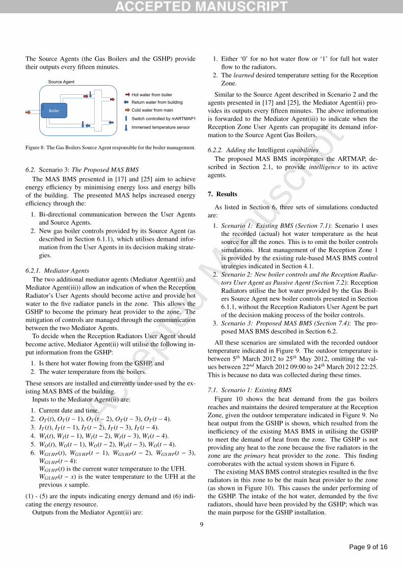
The Source Agents (the Gas Boilers and the GSHP) providetheir outputs every fifteen minutes.
Boiler
Source Agent
Hot water from boiler
Return water from building
Cold water from main
Switch controlled by mARTMAP1
Immersed temperature sensor
Figure 8: The Gas Boilers Source Agent responsible for the boiler management.
6.2. Scenario 3: The Proposed MAS BMSThe MAS BMS presented in [17] and [25] aim to achieve
energy efficiency by minimising energy loss and energy billsof the building. The presented MAS helps increased energyefficiency through the:
1. Bi-directional communication between the User Agentsand Source Agents.
2. New gas boiler controls provided by its Source Agent (asdescribed in Section 6.1.1), which utilises demand infor-mation from the User Agents in its decision making strate-gies.
6.2.1. Mediator AgentsThe two additional mediator agents (Mediator Agent(ii) and
Mediator Agent(iii)) allow an indication of when the ReceptionRadiator’s User Agents should become active and provide hotwater to the five radiator panels in the zone. This allows theGSHP to become the primary heat provider to the zone. Themitigation of controls are managed through the communicationbetween the two Mediator Agents.
To decide when the Reception Radiators User Agent shouldbecome active, Mediator Agent(ii) will utilise the following in-put information from the GSHP:
1. Is there hot water flowing from the GSHP, and2. The water temperature from the boilers.
These sensors are installed and currently under-used by the ex-isting MAS BMS of the building.
Inputs to the Mediator Agent(ii) are:
1. Current date and time.2. OT (t), OT (t − 1), OT (t − 2), OT (t − 3), OT (t − 4).3. IT (t), IT (t − 1), IT (t − 2), IT (t − 3), IT (t − 4).4. WI(t), WI(t − 1), WI(t − 2), WI(t − 3), WI(t − 4).5. WO(t), WO(t − 1), WO(t − 2), WO(t − 3), WO(t − 4).6. WGS HP(t), WGS HP(t − 1), WGS HP(t − 2), WGS HP(t − 3),
WGS HP(t − 4):WGS HP(t) is the current water temperature to the UFH.WGS HP(t − x) is the water temperature to the UFH at theprevious x sample.
(1) - (5) are the inputs indicating energy demand and (6) indi-cating the energy resource.
Outputs from the Mediator Agent(ii) are:
1. Either ‘0’ for no hot water flow or ‘1’ for full hot waterflow to the radiators.
2. The learned desired temperature setting for the ReceptionZone.
Similar to the Source Agent described in Scenario 2 and theagents presented in [17] and [25], the Mediator Agent(ii) pro-vides its outputs every fifteen minutes. The above informationis forwarded to the Mediator Agent(iii) to indicate when theReception Zone User Agents can propagate its demand infor-mation to the Source Agent Gas Boilers.
6.2.2. Adding the Intelligent capabilitiesThe proposed MAS BMS incorporates the ARTMAP, de-
scribed in Section 2.1, to provide intelligence to its activeagents.
7. Results
As listed in Section 6, three sets of simulations conductedare:
1. Scenario 1: Existing BMS (Section 7.1): Scenario 1 usesthe recorded (actual) hot water temperature as the heatsource for all the zones. This is to omit the boiler controlssimulations. Heat management of the Reception Zone 1is provided by the existing rule-based MAS BMS controlstrategies indicated in Section 4.1.
2. Scenario 2: New boiler controls and the Reception Radia-tors User Agent as Passive Agent (Section 7.2): ReceptionRadiators utilise the hot water provided by the Gas Boil-ers Source Agent new boiler controls presented in Section6.1.1, without the Reception Radiators User Agent be partof the decision making process of the boiler controls.
3. Scenario 3: Proposed MAS BMS (Section 7.4): The pro-posed MAS BMS described in Section 6.2.
All these scenarios are simulated with the recorded outdoortemperature indicated in Figure 9. The outdoor temperature isbetween 5th March 2012 to 25th May 2012, omitting the val-ues between 22nd March 2012 09:00 to 24th March 2012 22:25.This is because no data was collected during these times.
7.1. Scenario 1: Existing BMSFigure 10 shows the heat demand from the gas boilers
reaches and maintains the desired temperature at the ReceptionZone, given the outdoor temperature indicated in Figure 9. Noheat output from the GSHP is shown, which resulted from theinefficiency of the existing MAS BMS in utilising the GSHPto meet the demand of heat from the zone. The GSHP is notproviding any heat to the zone because the five radiators in thezone are the primary heat provider to the zone. This findingcorroborates with the actual system shown in Figure 6.
The existing MAS BMS control strategies resulted in the fiveradiators in this zone to be the main heat provider to the zone(as shown in Figure 10). This causes the under performing ofthe GSHP. The intake of the hot water, demanded by the fiveradiators, should have been provided by the GSHP; which wasthe main purpose for the GSHP installation.
9

Page 10 of 16
Accep
ted
Man
uscr
ipt
05/03/12 06:45 15/03/12 16:45 28/03/12 16:15 08/04/12 02:15 18/04/12 12:15 28/04/12 22:15 09/05/12 08:15 19/05/12 18:150
5
10
15
20
25O
utdo
or T
empe
ratu
re (
o C )
Figure 9: The recorded outdoor temperature between 5th March 2012 to 25th May 2012, omitting the hours of 22th March 2012 09:00 to 24th March 2012 22:24.No data were collected during these times.
05/03/12 06:45 15/03/12 16:45 28/03/12 16:15 08/04/12 02:15 18/04/12 12:15 28/04/12 22:15 09/05/12 08:15 19/05/12 18:15
0
20
40
60
80
100
120
Water Temperature to Radiator 1 (oC)
Water Temperature to Radiator 2 (oC)
Water Temperature to Radiator 3 (oC)
Water Temperature to Radiator 4 (oC)
Water Temperature to Radiator 5 (oC)
Desired Zone Temperature (oC)Heat Output from the GSHP (kW)
Figure 10: The water temperature provided to the five radiators in Reception Zone, the desired zone temperature and the GSHP heat output from Scenario 1.
10

Page 11 of 16
Accep
ted
Man
uscr
ipt
7.2. Scenario 2: Reception Radiators User Agent as PassiveAgent
Figure 11 shows the distribution (box plot) of the simu-lated sub-zone temperatures minus the desired zone temper-ature when the Reception Radiators User Agent is a passiveagent and the new boiler controls described in Section 6.1.1 areused. Similar simulated zone temperature values were recordedwhen compared against the two MAS BMS strategies: Scenar-ios 1 and 2.
Despite treating the Reception Radiators User Agent as apassive agent, the results demonstrate that the heat providedcan achieve and maintain the desired zone temperature, withless gas used and energy produced by the gas boilers. Heat isprovided by the hot water produced by the new boiler controls.This is in comparison to actual energy (heat) consumption ofthe building, as indicated in Table 1. The difference between theactual boiler temperature and the boiler temperature resultingfrom dynamic heat demand from the building with new boilercontrols is illustrated in Figure 13. Similar observation was de-scribed in [17] and [25].
7.3. Summarising the Results from Scenarios 1 and 2
Figures 10 and 12 show that because of the slow responsetime of the GSHP, the GSHP is not acting as the primary heatsource to the Reception Zone; even with the Reception Radia-tors User Agent as passive agent (Scenario 2). No heat is pro-vided by the GSHP because the five radiators in the zone areproviding the required heat for the zone.
This indicates the need for the new MAS BMS strategies re-quired to force the GSHP to become the primary heat providerfor the zone. The new MAS BMS is presented in Section 6.2and illustrated in Figure 7. Results from the new BMS Intelli-gent control strategies are presented in the following section.
Table 1: Comparing the Energy Usage with New Boiler Controls.
Energy used (MWh)Existing BMSa 55.009b
With new boiler controls27.0839b,c(Section 6.1.1)
without the Reception zoneWith new boiler controls 39.1618cwith the Reception zoneHeat required by the Reception 39.1618 - 27.0839zone = 12.0779a The actual energy used by the building between 1st
March to 25st May 2012. Information is estimatedbased on the information provided by the energyprovider e.on and the installed BMS.
b Data collected from [17].c Energy used is measured using the temperature differ-
ences between the provided hot water to the zone andits return water temperature.
7.4. Scenario 3: The Proposed MAS BMS
The new proposed BMS strategies adds Intelligence(ARTMAP) to all the active User Agents and to its Gas BoilersSource Agent in the MAS BMS. This is because these agentsare easily replaceable from the existing BMS. Figure 14 showsthe distributions of the simulated sub-zone temperatures for theReception Zone when its heat is managed by the proposed MASBMS illustrated in Figure 7.
Figure 14 shows Intelligence, provided by the ARTMAP,added to the GSHP User Agent helps ensure that the GSHPis the primary heat provider to the Reception Zone. The GSHPhas produced part of the required 12.0779MWh heat requiredby the zone. This is as indicated in Table 1. The GSHP has pro-vided the heat output of ≈11.7660MWh, which is equivalent to97.5% of the energy required to heat the Reception zone. Indoing so, the GSHP used 3.36MWh of electrical energy. Thisdemonstrates a system efficiency of ≥ 349%.
The greater use of the GSHP with the improved boiler con-trols have resulted in a 23% reduction in the building’s gas con-sumption. This can lead to lower carbon emissions and greaterenergy cost savings. Increased revenues may be achieved withthe addition of Renewable Heat Incentive payments from UKgovernment [31].
The performance of the GSHP means that the carbon costof the grid electricity used to power the heat pump is less thanthat equivalent heat energy from the gas supply. This furthercontribute to the lowering of the carbon emissions.
Table 2: Comparing the Energy Usage with the Proposed MAS BMS
Energy used (MWh)Existing BMS 55.0090With the proposed MAS BMS 38.6796a
Electricity used by the GSHP 3.36409a Energy used is measured using the temperature dif-
ferences between the provided hot water to the zoneand its return water temperature.
8. Summary & Conclusion
The existing multi agent building management system (MASBMS) at the UCLan Samuel Lindow Building (SLB) shows thatwithout the intelligent control strategies, the advantages of in-corporating its ground source heat pump (GSHP) energy tech-nology are not manifested.
This can be addressed by adding intelligence to the MASBMS. ARTMAP, a type of artificial neural network (ANN), wasintroduced to address this issue. The ARTMAP provides theintelligent capabilities to User Agents and the Source Agentsof the MAS BMS. This is to allow heat sources to provide heatbased on the dynamic heat demand of the building.
Simulation results presented in this paper show how a MASBMS with intelligence incorporated to its User Agents and
11

Page 12 of 16
Accep
ted
Man
uscr
ipt
−10
−8
−6
−4
−2
0
2
4
6
8
Scenario 1 Scenario 2 Scenario 3
Figure 11: The distribution (box plot) of the average Reception Zone 1 temperature minus the desired temperature for Scenarios 1, 2 and 3.
05/03/12 06:4515/03/12 16:4528/03/12 16:1508/04/12 02:1518/04/12 12:1528/04/12 22:1509/05/12 08:1519/05/12 18:15
0
20
40
60
80
100
120
Water Temperature to Radiator sub zone 1 ( oC )
Water Temperature to Radiator sub zone 2 ( oC )
Water Temperature to Radiator sub zone 3 ( oC )
Water Temperature to Radiator sub zone 4 ( oC )
Water Temperature to Radiator sub zone 5 ( oC )
Heat to Reception Zone provided by the GSHP (kW)
Desired Zone Temperature ( oC )
Figure 12: The water temperature provided to the radiators in Reception Zone, the desired zone temperature and the GSHP heat output to the zone from Scenario 2.
12

Page 13 of 16
Accep
ted
Man
uscr
ipt
05/03/12 06:4515/03/12 16:4528/03/12 16:1508/04/12 02:1518/04/12 12:1528/04/12 22:1509/05/12 08:1519/05/12 18:150
10
20
30
40
50
60
70
80
90
Wat
er te
mpe
ratu
re p
rodu
ced
by th
e bo
ilers
( o C
)
Recorded (actual) temperatureProduced using the new boiler controls (ARTMAP, Scenario 2)
Figure 13: The hot water temperature produced by the gas boilers when utilising the MAS BMS control strategies described in Section 6.1 (Scenario 2) and theactual hot water temperature.
05/03/12 06:4515/03/12 16:4528/03/12 16:1508/04/12 02:1518/04/12 12:1528/04/12 22:1509/05/12 08:1519/05/12 18:15
0
20
40
60
80
100
120
Water Temperature to Radiator sub zone 1 ( oC )
Water Temperature to Radiator sub zone 2 ( oC )
Water Temperature to Radiator sub zone 3 ( oC )
Water Temperature to Radiator sub zone 4 ( oC )
Water Temperature to Radiator sub zone 5 ( oC )
Heat to Reception Zone provided by the GSHP (kW)
Desired Zone Temperature ( oC )
Figure 14: The energy for the Reception Zone when utilising the proposed MAS BMS Scenario 3. Figure shows the GSHP is the main heat provider to the zone.
13

Page 14 of 16
Accep
ted
Man
uscr
ipt
05/03/12 06:4515/03/12 16:4528/03/12 16:1508/04/12 02:1518/04/12 12:1528/04/12 22:1509/05/12 08:1519/05/12 18:150
10
20
30
40
50
60
70
80
90
Wat
er te
mpe
ratu
re p
rodu
ced
by th
e bo
ilers
( o C
)
Scenario 2Scenario 3
Figure 15: The hot water produced by the gas boilers for Scenarios 2 and 3; resulted in the small energy saving indicated in Table 2.
Source Agents can help maximise the advantage of incorpo-rating the GSHP energy technology, which in turn helps in thereduction of energy costs and the lowering of CO2 gas emis-sions.
The implementation of the ARTMAP-MAS BMS is cur-rently underway within the university, beginning with the im-plementation of the User Agents to the rooms in the building.The work then continues with the implementation of the SourceAgents to the gas boilers and the GSHP; where issues in inte-grating the Source Agents with the existing control systems ofthe boilers and the GSHP are envisaged. Future work includes:investigating potential limitations of the integration and findingsolutions to the identified limitations, as well as investigatingthe suitability of the proposed MAS to provide cost effectiveintegration of multiple types of renewable electric generators tothe building.
Acknowledgement
The authors would like express their gratitude to the UCLanFacilities Management in all their help in providing informationwith regards to the heat demand and resources of the SamuelLindow Building. The work is joint funded by BAE Systems,UK.
[1] Zero Carbon Britain. [Online] http://www.zcb2030.org/
[2] A. Howe, “Dynamic demand could help balance electricity systems,” En-ergy World, Energy Institute, London, Nov. 2009.
[3] H. Esen, M. Inalli, A. Sengur and M. Esen, “Modelling a Ground-CoupledHeat Pump System Using Adaptive Neuro-Fuzzy Inference Systems”, In-ternational Journal of Refrigeration, vol. 31, no. 1, pp. 65-74, 2008.
[4] H. Esen, M. Inalli, A. Sengur and M. Esen, “Artificial Neural Networksand Adaptive Neuro-Fuzzy Assessments for Ground-Coupled Heat PumpSystem”, Energy and Buildings, vol. 40, no. 6, pp. 1074-1083, 2008.
[5] H. Esen and M. Inalli, “ANN and ANFIS models for performance evalua-tion of a vertical ground source heat pump system”, Expert Systems withApplications, vol. 37, no. 12, pp. 8134-8147, 2010.
[6] M. Mohanraja, S. Jayaraj and C. Muraleedharan, “Applications of arti-ficial neural networks for refrigeration, air-conditioning and heat pumpsystems - A review”, Renewable and Sustainable Energy Reviews, vol.16, no. 2, pp. 1340-1358, 2012.
[7] Energy Saving Trust, “Getting warmer: a field trial of heat pumps,”2010 [Online] http://itsacoastthing.com/pdf/EST_Getting_warmer_a_field_trial_of_heat_pumps_report[1].pdf
[8] N. Bergman, “Why is Renewable Heat Undeperforming? A Socio-Technical Perspective,” 2011 [Online] http://scholar.googleusercontent.com/scholar?q=cache:nY-EoZZqIysJ:scholar.google.com/+why+is+ re-newable+heat+underperforming&hl =en&as_sdt=0,5
[9] Energy Saving Trust, “Detailed analysis from the first phase of theEnergy Saving Trust’s heat pump field trial: Evidence to supportthe revision of the MCS Installer Standard,” MIS 3005, no 3.1,2012 [Online] http://www.decc.gov.uk/assets/decc/11/meeting-energy-demand/microgeneration/5045-heat-pump-field-trials.pdf
[10] S. Caird, R. Roy and S. Potter, “Domestic heat pumps in the UK: userbehaviour, satisfaction and performance,” Energy Efficiency, vol. 5, no. 3,pp. 283-301, 2012.
[11] X. Liu, I. Chilvers, M. Mokhtar, A. Bedford, K. Stitt and J. Yazdani, “Mi-crogrid Development for Properties”, in The 2nd European Conference onInnovative Intelligent Grid Technologies (ISGT- EUROPE 2011), 2011.
[12] Veissmann, Vitocell 300-B DHW cylinder with two indirect coils 300and 500 litre capacity, [Online] http://www.viessmann.co.uk/etc/ medi-alib/internet_uk/technical_updates.Par.73739.File.File.tmp/Vitocell300BDatasheet.pdf
[13] Veissmann, “Vitocal 300G Boiler and Heat Pump Data Sheet”,VITOCAL 300/350 Heat pump: Brine/Water - 6.4 to 32.6 kW, Wa-ter/Water - 8.4 to 43.0 kW, [Online] http://www.viessmann.co.uk/
etc/medialib/internet_uk/attachments/datasheets_technical/heat_pumps.
14

Page 15 of 16
Accep
ted
Man
uscr
ipt
Par.95308.File.File.tmp/Vitocal300350Datasheet.pdf[14] P. Davidsson and M. Boman, “Distributed Monitoring and Control of Of-
fice Buildings by Embedded Agents,” Information Sciences, vol. 171, pp.293-307, 2005.
[15] B. Shen, G. Zhang, L. Zhang and M. Wang, “Multi-Agent System Designfor Room Energy Saving”, in 2010 5th IEEE Conference on IndustrialElectronics and Applications, pp.840-844, 2010.
[16] B. Qiao, K. Liu, and C. G. Guy, “A multi-agent system for building con-trol”, In Proceedings of IEEE/WIC/ACM International Conference on In-telligent Agent Technology (IAT-6), Hong Kong, 2006.
[17] M. Mokhtar, X. Liu, “An ARTMAP-incorporated Multi-Agent Systemfor Building Intelligent Heat Management”, in The 3rd European Confer-ence on Innovative Intelligent Grid Technologies (ISGT- EUROPE 2012),2012.
[18] A. I. Dounis, D. E. Manolakis. “Design of a fuzzy system for living spacethermal comfort regulation”, Applied Energy 2001, vol. 69, pp. 119-144,2001.
[19] A.I. Dounis, C. Caraiscos, “Advanced control systems engineering for en-ergy and comfort management in a building environment - A review”. Re-newable and Sustainable Energy Reviews, Vol. 13, Issues 6-7, pp. 1246-1261, 2009.
[20] M. Gouda, S. Danaher, C. Underwood, “Thermal comfort based fuzzylogic controller”, Building Services Engineering Research and Technol-ogy 2001, vol. 22, no. 4, pp. 237-253, 2001.
[21] D. Kolokotsa, “Comparison of the performance of fuzzy controllers forthe management of the indoor environment”, Building and Environment,vol. 38, pp. 1439-1450, 2003.
[22] F. Calvino, M. L. Gennusca, G. Rizzo, G. Scaccianoce, “The control ofindoor thermal comfort conditions: introducing a fuzzy adaptive con-troller”, Energy and Buildings, vol. 36, pp. 97-102, 2004
[23] J. Liang and R. Du, “Thermal Comfort Control Based on Neural Networkfor HVAC Application”, Proceedings of the 2005 IEEE Conference onControl Applications, Toronto, Canada, August, 2005.
[24] F. Yamada, K. Yonezawa, S. Sugarawa, N. Nishimura, “Development ofair-conditioning control algorithm for building energy-saving,” In IEEEInternational Conference on Control Applications, 1999.
[25] M. Mokhtar, X. Liu, J. Howe, “Multi-Agent Gaussian Adaptive Reso-nance Theory Map for Building Energy Control and Thermal ComfortManagement of UCLan’s Westlakes Samuel Lindow Building”, Submit-ted to Energy and Building, Elsevier, 2012.
[26] J. Williamson, “Gaussian ARTMAP: A neural network for fast incremen-tal learning of noisy multidimensional maps,” Neural Networks, vol. 9,no. 5, pp. 881-897, 1996.
[27] G. Carpenter, S. Grossberg, and J. Reynolds, “ARTMAP: Supervised real-time learning and classification of nonstationary data by a self-organizingneural network,” Neural Network, vol. 4, pp. 565-588, 1991.
[28] G. Carpenter, S. Grossberg, N. Markuzon, J. Reynolds, and D. Rosen,“Fuzzy ARTMAP: A neural network architecture for incremental super-vised learning of analog multidimensional maps,” IEEE Trans. NeuralNetworks, vol. 3, no. 5, pp. 698-713, 1992.
[29] Matlab, “Thermal Model of a House,” [Online] Available: http://www.mathworks.co.uk/products/simulink/demos.html?file=/products/demos/shipping/simulink/sldemo_househeat.html
[30] ASHRAE Handbook Fundamentals, 2005.[31] Department of Energy & Climate Change, “Renew-
able Heat Incentive (RHI) Scheme,” [Online] Available:http://www.decc.gov.uk/en/content/cms/meeting_energy/renewable_ener/incentive/incentive.aspx
15

Page 16 of 16
Accep
ted
Man
uscr
ipt
Highlights
1. We created a UCLan Westlakes Samuel Lindow Building with GSHP heat simulation model.
2. We proposed an ARTMAP multi-agent intelligent heat management system.
3. ARTMAP provides better heat distribution in comparison to other systems.
4. The proposed technique has solved the underperforming issues of GSHP.
5. ARTMAP has caused lesser heat to be produced by the boilers.
*Highlights (for review)