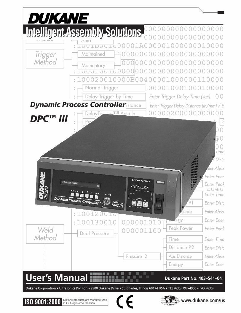
intelligent assembly solutions - dukane · dynamic processor controllertm dpc iii user’s manual...
TRANSCRIPT
:100000010000000000000000000000000000000000EF:100010010000000000000000000000000000000000DF:100020010000B004000010000001100000000000001B:100030010000000000001000100010000000000000BF:100040010000000000000000000000000000000000AF:100050010000000000000000000000000000E80300B4:1000600100000000000002C00000000000000000008F:1000700100000001000044430000000041C1C1CC0068:10008001000000000000C0000000404000C1C10000AD:1000900100000000000000000000DC0500000000007E:1000A00100000000000000000000000000000000004F:1000B00100000000008B0100000000000000000000B3:1000C00100000000000000000000000000000000002F:1000D00100000000000000000000000000000000001F:1000E00100000000000000000000000000000000000F:1000F00100000000001000000000E20400FBD400004A:100100010000000001000000000000000000000000EE:100110010000000011130100000000000000000000CA:100120010000000000000000000000000000000000CE:100130010000000101000000000000000000000000BE:100140010000000110000000000000000000000000AE
:1001A00100010D00000010001000100000000000004E:1001B00100020EE00000000000000000000000000030:1001C001000202F0000000000000000000000000002E:1001D001000001A0000010000000100000000000001E:1001E00100000000000000000000000000000000000E
:100200010000000000000000000000000000000000ED:10021001000000000400000000000500006400000070:100220010000000000000000000000005365747570BC:100230010020322020202020202020202020202020AB:100240010020202020202020202020202020202020AD:1002500100202020000000000000000000000000003D:1002600100000000000000000000000000000000008D:1002700100000009090900000000DC0009090900006B:07028001000000000000000076:0000000100FF
InitateMode
Scrub
Manual
Auto
Maintained
Momentary
Enter Trigger Delay Time (sec)
Enter Trigger Delay Distance (in/mm) / Enter Max. Delay Time (sec)
Enter Probe Delay Time (sec)
Enter Pre-Trig Distance (in/mm)
Disabled
Enabled Enter Scrub Time (sec)
TriggerMethod
Probe Delay
Normal Trigger
Probe Mode
Delay Trigger by Distance
Delay Trigger by Time
DelayTrigger Till Auto In
Pre-trigger by Dist
WeldMethod
Enter Time (sec)
Enter Distance (in/mm) / Enter Max. Weld Time (sec)
Enter Absolute Distance (in/mm) / Enter Max. Weld Time (sec)
Enter Peak Power (watts) / Enter Max. Weld Time (sec)
Enter Energy (joules) / Enter Max. Weld Time (sec)
Enter Time (sec)
Enter Distance (in/mm) / Enter Max. Weld Time (sec)
Enter Absolute Distance (in/mm) / Enter Max. Weld Time (sec)
Enter Peak Power (watts) / Enter Max. Weld Time (sec)
Enter Energy (joules) / Enter Max. Weld Time (sec)
Enter Time (sec)
Enter Distance (in/mm) / Enter Max. Weld Time (sec)
Enter Absolute Distance (in./mm) / Enter Max. Weld Time (sec)
Enter Peak Power (watts) / Enter Max. Weld Time (sec )
Enter Reporting Interval (sec)
Enter Energy (joules) / Enter Max. Weld Time (sec)
Pressure 1
Pressure 2
Time
Peak Power
Abs Distance
Distance
Energy
Time
Peak Power
Abs Distance
Distance P1
Energy
Time
Peak Power
Abs Distance
Distance P2
Energy
Dual Pressure
Single Pressure
Continuous
AfterburstDisabled
Enabled
HoldMethod
Hold by Time Enter Hold Time (sec)
Enter Hold Distance (in/mm) / Enter Max. Hold Time (sec)Hold by Dist
Trigger
Pre-trigger
Enable Hold
Disable Hold
Delay Enter Delay Time (sec)
Enter Duration (sec)Duration
Start Weld At
www.dukane.com/us
Dukane Corporation • Ultrasonics Division • 2900 Dukane Drive • St. Charles, Illinois 60174 USA • TEL (630) 797–4900 • FAX (630)
Dukane Part No. 403–541–04User’s Manual
Intelligent Assembly SolutionsIntelligent Assembly Solutions
Dynamic Process Controller
DPC™ III
ISO 9001:2000 Dukane products are manufactured in ISO registered facilities
Dynamic Processor ControllerTM DPC III User’s Manual
ii iii
Dynamic Processor ControllerTM DPC III User’s Manual
ii iii
Printed in the United States of America.
Dukane Part Number: 403–541–04
Dukane ultrasonic equipment is manufactured under one or more of the followingU.S. Patents:3,780,926 3,825,481 4,131,505 4,277,710 5,798,599 and 5,880,580.
DataMyte is a registered trademark of DataMyte Corporation.Epson is a registered trademark of Epson Corporation.HyperTerminal is a registered trademark of Microsoft Corporation.IBM is a registered trademark of International Business Machines Corporation.Intel is a registered trademark of Intel Corporation.Kinechek is a registered trademark of Deschner Corporation.Lotus and 1-2-3 are registered trademarks of Lotus Development Corporation.Microsoft, and Excel are registered trademarks of Microsoft Corporation.Sherwood is a registered trademark of Inkel Technology, Inc.Windows 95, Windows 98, Windows 2000, Windows XP and Windows NT
are trademarks of Microsoft Corporation.
Copyright © 2000—2004 Dukane Corporation
Notice of Rights:All rights reserved. No part of this manual including the interior design, cover design and icons may be reproduced, transmitted or utilized in any form or by any means, elec-tronic, mechanical, photocopying, recording, or by any information storage and retrieval system, without written permission from Dukane Corporation.
Notice of Liability:The information contained is this manual is distributed on an “As is” basis, without warranty. While every precaution has been taken in the preparation of this manual, Dukane Corporation shall not have any liability to any person or entity with respect to any liability, loss, or damaged caused or alleged to be caused directly or indirectly by the instruc-tions contained in this manual, or by the hardware products described herein.
Dynamic Processor ControllerTM DPC III User’s Manual
ii iii
Dynamic Processor ControllerTM DPC III User’s Manual
ii iii
Revision History
Revision Revision Number History Date ––– Original release. 2000-Apr-12
–01 Incorporate Addendum 1 (Amplitude Control standard feature) 2002–Jun–06 Incorporate Addendum 2 (Jumper Block for Hand Probe) Update Generator Model Number in Table 12–1 Update Interpreting the DPC Model No. in Figure 12–2
–02 Revise Hand Probe instructions on pages 19, 52, 53 & 60 2002-Oct-23 Corrections to Top–Of–Stroke connector pinout diagram (Figure A–8) on page A–XVII in Appendix A.
–03 Remove all references to obsolete DDeX commands. 2004-Jan-16 Remove references to obsolete Remote Setup Commands. Remove references to discontinued Force Transducer/Load Cell. Remove references to discontinued Electronic Pressure Regulator. Remove references to discontinued Pressure Transducer. ModifyIndexandTOCtoreflectdeletionsandpagenumberchanges. UpdatemenuflowchartsinAppendixD(PreviouslyAppendixF) toreflectchanges. AddnewfunctionstoCommunications–>OutputMode
–04 UpdateTable2—1,PackingContentstoreflectRev–4manual. 2004-Nov-15 UpdateTable2–3toreflectnewpartnumbers. Table2–2and2–3nowindicateCable200–740onlysupplied withAdvancedProgrammeroption. TerminalsuppliedwithAdvancedProgrammeroptionhasdifferent DPCconnections.Replaceddiagramsonpages17,18and144. Replaceinstructionsforenteringsetupmodetoconfiguremonitor and connecting printers in Section 13, pages 141–145. AddTableC–4whichprovidedescriptionsof CSVtagnumbers. Figure A–1 (I/O Jumper Location) restored. Figure became corrupted in revision –03. Newconsolidatedwarrantyand24–HourServicenumber. UpdatecertificationtoISO9001:2000. UpdateIndextoreflectnewinformationandchangedpagenumbers.
Update Dukane Contacts Page. 2010-July-8 Update Regulatory Agency Compliance Statement. UpdateDukanewebsiteaddress.
DPC–III User’s Manual

Dynamic Processor ControllerTM DPC III Plus User’s Manual
iv
This page intentionally left blank

Table of Contents
v
TableofContentsSection1IntroductionandSafety
BeforeOperatingEquipment................................................................................ 1ReadthisManualFirst.................................................................................... 1WatchforSpecialParagraphs........................................................................ 1
AboutthisManual............................................................................................... 2Contents........................................................................................................ 2Organization................................................................................................. 2
DPCOverview.................................................................................................... 4KeyFeatures....................................................................................................... 4HealthandSafetyRecommendations.................................................................... 6
SpecialHealthNotice–Plastics....................................................................... 7ElectricalSafetyGroundingInstructions........................................................... 7
120VoltGroundAdapter......................................................................... 8InternationalGrounding............................................................................ 9AdditionalGrounding.............................................................................. 9
RFIFilterConsiderations................................................................................ 9
Section2InstallationUnpacking........................................................................................................ 11DPCPlacement................................................................................................. 11
Benchtop.................................................................................................... 11Rack-mounted.............................................................................................. 12
RearPanelLayout............................................................................................. 13GroundtheSystem............................................................................................ 15ConnecttheCables........................................................................................... 15
TheAdvancedProgrammer.......................................................................... 17Overview............................................................................................... 17Connections........................................................................................... 17
HandProbeConnections.............................................................................. 19ComputerConnections................................................................................. 19GroundDetectFeatureConnections............................................................... 20RecheckConnections.................................................................................... 20ConnectElectricalPower.............................................................................. 20
Dynamic Processor ControllerTM DPC III User’s Manual
vi
Overview......................................................................................................... 21FrontPanelLayout............................................................................................. 21
FrontPanelDisplayandKeypadOverview.................................................... 22Display.................................................................................................. 22Keypad.................................................................................................. 22
KeypadDetails............................................................................................ 23TheCancelKey...................................................................................... 23TheEnterKey......................................................................................... 24TheDownArrowKey.............................................................................. 25TheUpArrowKey.................................................................................. 25TheLeftArrowKey................................................................................. 26TheRightArrowKey............................................................................... 26ModeSelectionKeyswitch....................................................................... 27
GeneratorStatusPanel................................................................................. 28GeneratorControl.................................................................................. 28SystemStatus......................................................................................... 29SystemPowerOutput.............................................................................. 30
ACPower................................................................................................... 30TheAdvancedProgrammerKeyboard................................................................ 31
FunctionKeys.............................................................................................. 31ProgrammingaFunctionKey........................................................................ 32RemovingaFunctionKey’sProgram.............................................................. 32MiscellaneousKeyFunctions......................................................................... 33BlockingAccesstoSETUPMode.................................................................... 34
Section4Start-upOverview......................................................................................................... 35Start-upwithoutAdvancedProgrammer............................................................. 35Start-upwithAdvancedProgrammer.................................................................. 36StoppingtheWeldCycle................................................................................... 38
NormalConditions...................................................................................... 38EmergencyConditions.................................................................................. 38
TableofContentsSection3Controls
Table of Contents
vii
Section5MenuOrientationOverview......................................................................................................... 39
TermstoKnow............................................................................................. 40MenuItem.............................................................................................. 40Page...................................................................................................... 40Menu..................................................................................................... 40
EntryFields................................................................................................. 41NumericEntryField................................................................................ 41ListEntryField........................................................................................ 41TextEntryField....................................................................................... 42
NavigatinginSETUPMode.......................................................................... 43HowtoNavigate......................................................................................... 44
UsingtheFrontPanelControls................................................................. 44UsingtheAdvancedProgrammer............................................................. 46
NavigatinginOPERATEMode...................................................................... 48
TableofContents
Section6SetupMode,ProcessControlPageOverview......................................................................................................... 49ProcessControlPage......................................................................................... 50
StartingDisplays.......................................................................................... 51InitiateMode.................................................................................................... 52
Manual....................................................................................................... 52ProbeMethod........................................................................................ 52AllOtherTriggerMethods....................................................................... 52
Auto........................................................................................................... 53TriggerMethod................................................................................................. 54
TriggerType................................................................................................ 54Maintained............................................................................................ 54Momentary............................................................................................ 55Force..................................................................................................... 55TriggerMethod1:NormalTrigger........................................................... 56TriggerMethod2:DelaybyTime............................................................. 56TriggerMethod3:DelaybyDistance........................................................ 57TriggerMethod4:DelaytillAuto-In......................................................... 57TriggerMethod5:Pre-triggerbyDistance................................................ 59TriggerMethod6:Probe......................................................................... 60
Dynamic Processor ControllerTM DPC III User’s Manual
viii
TableofContents
Section8SetupMode,CommunicationsPage
TableofContentsSection6SetupMode,ProcessControlPage,continued
WeldMethod.................................................................................................... 61SinglePressure............................................................................................ 61DualPressure.............................................................................................. 61Continuous.................................................................................................. 62
EnteringReportInterval........................................................................... 62ControlParameters–SingleandDualPressureWelding................................. 63
Time...................................................................................................... 63Distance................................................................................................. 63AbsoluteDistance................................................................................... 64Energy................................................................................................... 64PeakPower............................................................................................ 64MaximumWeldTime.............................................................................. 64
Scrub............................................................................................................... 65HoldMethod.................................................................................................... 66
Disable....................................................................................................... 66HoldMethodChoices................................................................................... 66
HoldbyTime.......................................................................................... 66HoldbyDistance.................................................................................... 66
Afterburst......................................................................................................... 67SecondaryControls........................................................................................... 68
Section7SetupMode,ProcessLimitsPageOverview......................................................................................................... 69AvailableProcessCharacteristics........................................................................ 71ProcessCharacteristicsDefined.......................................................................... 71BadLimits......................................................................................................... 75
BadLimitsStatusField.................................................................................. 76Disabled................................................................................................ 76Display.................................................................................................. 76Window................................................................................................ 76
SuspectLimits.................................................................................................... 77SuspectLimitsStatusField............................................................................. 78
Disabled................................................................................................ 78Enabled................................................................................................. 78
EnablingProcessLimits...................................................................................... 79SecondaryControl............................................................................................ 80
NotAllCharacteristicsHaveSecondaryControl............................................. 80
Overview......................................................................................................... 81ConfigureSerialPort......................................................................................... 82
OutputDevice.............................................................................................. 83DeviceTypes.......................................................................................... 84
OutputMode............................................................................................... 85BaudRate................................................................................................... 85Protocol...................................................................................................... 86
Xon/Xoff................................................................................................ 86RTS/CTS................................................................................................ 86
LFAfterCR.................................................................................................. 87LimitIndicators............................................................................................ 87TimeTag..................................................................................................... 88
UserI/O.......................................................................................................... 88Outputs....................................................................................................... 88EndofWeld/GroundDetect......................................................................... 89StatusOutputs............................................................................................. 90DefineJ801-5As......................................................................................... 90
GoodPart.............................................................................................. 90InDwell................................................................................................. 90InCycle................................................................................................. 91SonicsOn.............................................................................................. 91
Table of Contents
ix
TableofContents
Section8SetupMode,CommunicationsPage
TableofContentsSection6SetupMode,ProcessControlPage,continued
WeldMethod.................................................................................................... 61SinglePressure............................................................................................ 61DualPressure.............................................................................................. 61Continuous.................................................................................................. 62
EnteringReportInterval........................................................................... 62ControlParameters–SingleandDualPressureWelding................................. 63
Time...................................................................................................... 63Distance................................................................................................. 63AbsoluteDistance................................................................................... 64Energy................................................................................................... 64PeakPower............................................................................................ 64MaximumWeldTime.............................................................................. 64
Scrub............................................................................................................... 65HoldMethod.................................................................................................... 66
Disable....................................................................................................... 66HoldMethodChoices................................................................................... 66
HoldbyTime.......................................................................................... 66HoldbyDistance.................................................................................... 66
Afterburst......................................................................................................... 67SecondaryControls........................................................................................... 68
Section7SetupMode,ProcessLimitsPageOverview......................................................................................................... 69AvailableProcessCharacteristics........................................................................ 71ProcessCharacteristicsDefined.......................................................................... 71BadLimits......................................................................................................... 75
BadLimitsStatusField.................................................................................. 76Disabled................................................................................................ 76Display.................................................................................................. 76Window................................................................................................ 76
SuspectLimits.................................................................................................... 77SuspectLimitsStatusField............................................................................. 78
Disabled................................................................................................ 78Enabled................................................................................................. 78
EnablingProcessLimits...................................................................................... 79SecondaryControl............................................................................................ 80
NotAllCharacteristicsHaveSecondaryControl............................................. 80
Overview......................................................................................................... 81ConfigureSerialPort......................................................................................... 82
OutputDevice.............................................................................................. 83DeviceTypes.......................................................................................... 84
OutputMode............................................................................................... 85BaudRate................................................................................................... 85Protocol...................................................................................................... 86
Xon/Xoff................................................................................................ 86RTS/CTS................................................................................................ 86
LFAfterCR.................................................................................................. 87LimitIndicators............................................................................................ 87TimeTag..................................................................................................... 88
UserI/O.......................................................................................................... 88Outputs....................................................................................................... 88EndofWeld/GroundDetect......................................................................... 89StatusOutputs............................................................................................. 90DefineJ801-5As......................................................................................... 90
GoodPart.............................................................................................. 90InDwell................................................................................................. 90InCycle................................................................................................. 91SonicsOn.............................................................................................. 91
Dynamic Processor ControllerTM DPC III User’s Manual
x
TableofContentsSection9SetupMode,UtilitiesPage,continued
EncoderUtilities.............................................................................................. 106EncoderUnits............................................................................................ 106EncoderPosition........................................................................................ 106
Reset/PresetPartCount................................................................................... 107ResetPartCount........................................................................................ 107PresetPartCount....................................................................................... 107
UserParameters.............................................................................................. 107JobNumber.............................................................................................. 107Horn......................................................................................................... 108Booster..................................................................................................... 108Fixture...................................................................................................... 108Pressure1................................................................................................. 108Pressure2................................................................................................. 108TriggerForce............................................................................................. 109
PowerUtilities(EnergySystemsOnly)............................................................... 110PowerAverage.......................................................................................... 110Power....................................................................................................... 110
Section8SetupMode,CommunicationsPage,continued
TableofContents
DefineJ801-6As......................................................................................... 91Ready.................................................................................................... 91GoodPart,InCycle,andSonicsOn......................................................... 91
BuzzerStatus............................................................................................... 92AdvancedProgrammer...................................................................................... 93
Status.......................................................................................................... 93BaudRate................................................................................................... 93
PartSampling................................................................................................... 94ConsecutiveMemory............................................................................... 94SampleMemory..................................................................................... 94
LotSizeandSampleSize................................................................................... 94LotSize....................................................................................................... 94SampleSize................................................................................................ 95Exclude....................................................................................................... 96Store........................................................................................................... 96
Graphing......................................................................................................... 97LeftandRightAxis....................................................................................... 97StartAt....................................................................................................... 97StopAt....................................................................................................... 97SelectingTime,Power,andDistanceScales.................................................... 98
Section9SetupMode,UtilitiesPageOverview......................................................................................................... 99SetupUtilities.................................................................................................. 100
SelectNewSetup....................................................................................... 100CopyaSetup............................................................................................ 101EraseSetups.............................................................................................. 101
EraseCurrentSetup.............................................................................. 102EraseAllSetups.................................................................................... 102
PrintSetup................................................................................................. 102PrintSetup-Text.................................................................................... 102PrintSetup-Hex................................................................................... 104
TimeandDateUtilities..................................................................................... 105SetDate.................................................................................................... 105SetTime.................................................................................................... 105CheckDate............................................................................................... 105CheckTime............................................................................................... 105DateFormat.............................................................................................. 105
Section10SetupMode,SequencingPageOverview....................................................................................................... 111WhatisaSequence?....................................................................................... 112ExampleSequence.......................................................................................... 113Sequencing.................................................................................................... 114
Disabled................................................................................................... 114Enabled.................................................................................................... 114
SegmentLength.................................................................................... 114ResetSequence..................................................................................... 114DefinePartAs...................................................................................... 115
Cycle.............................................................................................. 115Sequence........................................................................................ 115
PresetSegment..................................................................................... 115PresetCycles........................................................................................ 115
Sequence....................................................................................................... 116SelectSegment.......................................................................................... 116SelectSetup............................................................................................... 116
FunctionKeysandSequencing......................................................................... 117
Table of Contents
xi
TableofContentsSection9SetupMode,UtilitiesPage,continued
EncoderUtilities.............................................................................................. 106EncoderUnits............................................................................................ 106EncoderPosition........................................................................................ 106
Reset/PresetPartCount................................................................................... 107ResetPartCount........................................................................................ 107PresetPartCount....................................................................................... 107
UserParameters.............................................................................................. 107JobNumber.............................................................................................. 107Horn......................................................................................................... 108Booster..................................................................................................... 108Fixture...................................................................................................... 108Pressure1................................................................................................. 108Pressure2................................................................................................. 108TriggerForce............................................................................................. 109
PowerUtilities(EnergySystemsOnly)............................................................... 110PowerAverage.......................................................................................... 110Power....................................................................................................... 110
Section8SetupMode,CommunicationsPage,continued
TableofContents
DefineJ801-6As......................................................................................... 91Ready.................................................................................................... 91GoodPart,InCycle,andSonicsOn......................................................... 91
BuzzerStatus............................................................................................... 92AdvancedProgrammer...................................................................................... 93
Status.......................................................................................................... 93BaudRate................................................................................................... 93
PartSampling................................................................................................... 94ConsecutiveMemory............................................................................... 94SampleMemory..................................................................................... 94
LotSizeandSampleSize................................................................................... 94LotSize....................................................................................................... 94SampleSize................................................................................................ 95Exclude....................................................................................................... 96Store........................................................................................................... 96
Graphing......................................................................................................... 97LeftandRightAxis....................................................................................... 97StartAt....................................................................................................... 97StopAt....................................................................................................... 97SelectingTime,Power,andDistanceScales.................................................... 98
Section9SetupMode,UtilitiesPageOverview......................................................................................................... 99SetupUtilities.................................................................................................. 100
SelectNewSetup....................................................................................... 100CopyaSetup............................................................................................ 101EraseSetups.............................................................................................. 101
EraseCurrentSetup.............................................................................. 102EraseAllSetups.................................................................................... 102
PrintSetup................................................................................................. 102PrintSetup-Text.................................................................................... 102PrintSetup-Hex................................................................................... 104
TimeandDateUtilities..................................................................................... 105SetDate.................................................................................................... 105SetTime.................................................................................................... 105CheckDate............................................................................................... 105CheckTime............................................................................................... 105DateFormat.............................................................................................. 105
Section10SetupMode,SequencingPageOverview....................................................................................................... 111WhatisaSequence?....................................................................................... 112ExampleSequence.......................................................................................... 113Sequencing.................................................................................................... 114
Disabled................................................................................................... 114Enabled.................................................................................................... 114
SegmentLength.................................................................................... 114ResetSequence..................................................................................... 114DefinePartAs...................................................................................... 115
Cycle.............................................................................................. 115Sequence........................................................................................ 115
PresetSegment..................................................................................... 115PresetCycles........................................................................................ 115
Sequence....................................................................................................... 116SelectSegment.......................................................................................... 116SelectSetup............................................................................................... 116
FunctionKeysandSequencing......................................................................... 117
Dynamic Processor ControllerTM DPC III User’s Manual
xii
Section13CareandTroubleshootingCare.............................................................................................................. 131
Environment.............................................................................................. 131FrontPanel................................................................................................ 131
Cleaning.............................................................................................. 131ReplaceableParts...................................................................................... 132
Troubleshooting.............................................................................................. 133DPCIIIErrorandWarningMessages................................................................ 134
LatchedError/WarningMessages............................................................... 134UnlatchedError/WarningMessages........................................................... 134
ErrorMessages............................................................................................... 135WarningMessages......................................................................................... 140AdvancedProgrammerReset........................................................................... 141
ResettingtheAdvancedProgrammer........................................................... 141ResettingtheMonitor............................................................................ 141SelectingaPrinterPort.......................................................................... 143PrintingtheAdvancedProgrammerScreen............................................. 145
VerifyingModuleOperation............................................................................ 146DistanceModule........................................................................................ 146EnergyModule.......................................................................................... 147ElectronicPressureRegulatorandthePressureTransducer............................. 147
CheckingtheOperationofInputs..................................................................... 148ControlInputs............................................................................................ 148
Auto-In................................................................................................ 148CycleStop............................................................................................ 149TriggerSwitch...................................................................................... 149EndofWeld/GroundDetect.................................................................. 149ActivationSwitches–SS1andSS2........................................................ 149
EffectsofI/OandSystemErrorsonProcessFlow.............................................. 150AnUninterruptedCycle.............................................................................. 150TheCycleTerminatesDuringDownstroke..................................................... 151PrematureWeldTermination....................................................................... 152
Miscellaneous................................................................................................. 154TheDPCWon’tCycle................................................................................. 154NoUltrasound........................................................................................... 155
Section11OperateMode,OperatePageOverview....................................................................................................... 119OperatePagewithFrontPanel......................................................................... 120
SelecttheOperateMode............................................................................ 120ReviewingProcessCharacteristics................................................................ 120AccessingOperateFunctions...................................................................... 120
OperatePagewithAdvancedProgrammer....................................................... 121SelecttheOperateMode............................................................................ 121ReviewingProcessCharacteristics................................................................ 121AccessingOperateFunctions...................................................................... 121
OperateFunctions........................................................................................... 122FunctionKeys............................................................................................ 122PrintPartMemory...................................................................................... 122PrintHeaders............................................................................................. 122DisplayPartMemory................................................................................. 123PrintGraph............................................................................................... 123
TEXT.................................................................................................... 123RawData............................................................................................. 124
ResetSequence.......................................................................................... 125
Section12SpecificationsRegulatoryAgencyCompliance....................................................................... 127Dimensions..................................................................................................... 128PowerSupplyElectricalSourceRequirements.................................................... 129GeneratorModels........................................................................................... 129OperatingEnvironment................................................................................... 129InterpretingtheDPCModelNumber................................................................. 130
TableofContents TableofContents
Table of Contents
xiii
Section13CareandTroubleshootingCare.............................................................................................................. 131
Environment.............................................................................................. 131FrontPanel................................................................................................ 131
Cleaning.............................................................................................. 131ReplaceableParts...................................................................................... 132
Troubleshooting.............................................................................................. 133DPCIIIErrorandWarningMessages................................................................ 134
LatchedError/WarningMessages............................................................... 134UnlatchedError/WarningMessages........................................................... 134
ErrorMessages............................................................................................... 135WarningMessages......................................................................................... 140AdvancedProgrammerReset........................................................................... 141
ResettingtheAdvancedProgrammer........................................................... 141ResettingtheMonitor............................................................................ 141SelectingaPrinterPort.......................................................................... 143PrintingtheAdvancedProgrammerScreen............................................. 145
VerifyingModuleOperation............................................................................ 146DistanceModule........................................................................................ 146EnergyModule.......................................................................................... 147ElectronicPressureRegulatorandthePressureTransducer............................. 147
CheckingtheOperationofInputs..................................................................... 148ControlInputs............................................................................................ 148
Auto-In................................................................................................ 148CycleStop............................................................................................ 149TriggerSwitch...................................................................................... 149EndofWeld/GroundDetect.................................................................. 149ActivationSwitches–SS1andSS2........................................................ 149
EffectsofI/OandSystemErrorsonProcessFlow.............................................. 150AnUninterruptedCycle.............................................................................. 150TheCycleTerminatesDuringDownstroke..................................................... 151PrematureWeldTermination....................................................................... 152
Miscellaneous................................................................................................. 154TheDPCWon’tCycle................................................................................. 154NoUltrasound........................................................................................... 155
Section11OperateMode,OperatePageOverview....................................................................................................... 119OperatePagewithFrontPanel......................................................................... 120
SelecttheOperateMode............................................................................ 120ReviewingProcessCharacteristics................................................................ 120AccessingOperateFunctions...................................................................... 120
OperatePagewithAdvancedProgrammer....................................................... 121SelecttheOperateMode............................................................................ 121ReviewingProcessCharacteristics................................................................ 121AccessingOperateFunctions...................................................................... 121
OperateFunctions........................................................................................... 122FunctionKeys............................................................................................ 122PrintPartMemory...................................................................................... 122PrintHeaders............................................................................................. 122DisplayPartMemory................................................................................. 123PrintGraph............................................................................................... 123
TEXT.................................................................................................... 123RawData............................................................................................. 124
ResetSequence.......................................................................................... 125
Section12SpecificationsRegulatoryAgencyCompliance....................................................................... 127Dimensions..................................................................................................... 128PowerSupplyElectricalSourceRequirements.................................................... 129GeneratorModels........................................................................................... 129OperatingEnvironment................................................................................... 129InterpretingtheDPCModelNumber................................................................. 130
TableofContents TableofContents
Dynamic Processor ControllerTM DPC III User’s Manual
xiv
Figures 1-1 Exampleof120V,Grounded,3-ProngReceptacle.........................................7 1-2 Exampleof220V,Grounded,3-ProngReceptacle.........................................7 1-3 Exampleof120VGroundAdapterHookup..................................................8 1-4 ExampleofInternational220/240VGrounding............................................9 1-5 TypicalEquipmentGroundingArrangement...................................................9 2-1 PlacingaBenchtopDPC.............................................................................11 2-2 Rack-mountedDPCUsingBracketKit...........................................................12 2-3 DPCRearPanel........................................................................................13 2-4 DPCCablingConnections...........................................................................16 2-5 AdvancedProgrammertoDPCIIIConnection...............................................17 2-6 AdvancedProgrammerSerialPrinterConnection.........................................18 2-7 KeyboardConnectorandPowerSwitchonAdvancedProgrammer..............18 2-8 ProbeCabling...........................................................................................19 2-9 GroundDetectFixtureInstallation................................................................20 3-1 FrontPanelLayout......................................................................................21 3-2 KeypadFunctions......................................................................................22 3-3 FrontPanelKeyswitch.................................................................................27 3-4 GeneratorStatusPanel...............................................................................28 3-5 GeneratorControlKeys..............................................................................28 3-6 SystemStatusDisplay.................................................................................29 3-7 NormalOperationIndicators......................................................................30 3-8 WarningIndicators....................................................................................30 3-9 ACPowerSwitch.......................................................................................303-10 AdvancedProgrammerKeyboard..............................................................313-11 AdvancedProgrammerSpecialPurposeKeys..............................................334-1 RightSideViewAdvancedProgrammer......................................................36 4-2 DisplaysatStart-up....................................................................................37 5-1 DPCIIIMenuOrganization.........................................................................39 5-2 NavigatinginSETUPMode........................................................................43 5-3 FrontPanelKeyFunctions...........................................................................44 5-4 NavigatingwiththeFrontPanel..................................................................45 5-5 AdvancedProgrammerSpecialPurposeKeys..............................................46 5-6 NavigatingontheAdvancedProgrammerDisplay.......................................47 5-7 NavigatinginOPERATEMode....................................................................48 6-1 SETUPModePages....................................................................................49 6-2 ProcessControlPageMenu........................................................................50 6-3 AdvancedProgrammerProcessControlDisplay...........................................51 6-4 FrontPanelProcessControlDisplay.............................................................51 6-5 DukaneWeldCycleComponents................................................................58
TableofContentsTableofContentsSection14DukaneCorporationContactsandWarranty
ContactingDukaneCorporation....................................................................... 157LocalSupport................................................................................................. 157
TryOurWebsite........................................................................................ 157ContactsintheUltrasonicsDivision............................................................. 157UltrasonicsDivisionE-mailAddresses.......................................................... 158UltrasonicsDivisionPhoneNumbers............................................................ 158
DukaneCorporationWarrantyUSA,Canada,Mexico............................................................................... 159International.............................................................................................. 160
Section15AppendicesAppendixA – Input/OutputInterfaceBoardAppendixB – ConnectorPinoutDescriptionsAppendixC – ExternalSerialDeviceSupportAppendixD – ReferenceGuidetoDPCIIIMenuStructure
Index
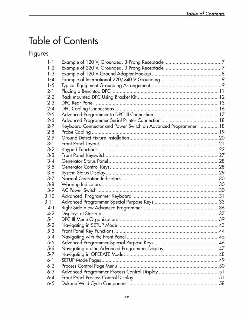
Table of Contents
xv
Figures 1-1 Exampleof120V,Grounded,3-ProngReceptacle.........................................7 1-2 Exampleof220V,Grounded,3-ProngReceptacle.........................................7 1-3 Exampleof120VGroundAdapterHookup..................................................8 1-4 ExampleofInternational220/240VGrounding............................................9 1-5 TypicalEquipmentGroundingArrangement...................................................9 2-1 PlacingaBenchtopDPC.............................................................................11 2-2 Rack-mountedDPCUsingBracketKit...........................................................12 2-3 DPCRearPanel........................................................................................13 2-4 DPCCablingConnections...........................................................................16 2-5 AdvancedProgrammertoDPCIIIConnection...............................................17 2-6 AdvancedProgrammerSerialPrinterConnection.........................................18 2-7 KeyboardConnectorandPowerSwitchonAdvancedProgrammer..............18 2-8 ProbeCabling...........................................................................................19 2-9 GroundDetectFixtureInstallation................................................................20 3-1 FrontPanelLayout......................................................................................21 3-2 KeypadFunctions......................................................................................22 3-3 FrontPanelKeyswitch.................................................................................27 3-4 GeneratorStatusPanel...............................................................................28 3-5 GeneratorControlKeys..............................................................................28 3-6 SystemStatusDisplay.................................................................................29 3-7 NormalOperationIndicators......................................................................30 3-8 WarningIndicators....................................................................................30 3-9 ACPowerSwitch.......................................................................................303-10 AdvancedProgrammerKeyboard..............................................................313-11 AdvancedProgrammerSpecialPurposeKeys..............................................334-1 RightSideViewAdvancedProgrammer......................................................36 4-2 DisplaysatStart-up....................................................................................37 5-1 DPCIIIMenuOrganization.........................................................................39 5-2 NavigatinginSETUPMode........................................................................43 5-3 FrontPanelKeyFunctions...........................................................................44 5-4 NavigatingwiththeFrontPanel..................................................................45 5-5 AdvancedProgrammerSpecialPurposeKeys..............................................46 5-6 NavigatingontheAdvancedProgrammerDisplay.......................................47 5-7 NavigatinginOPERATEMode....................................................................48 6-1 SETUPModePages....................................................................................49 6-2 ProcessControlPageMenu........................................................................50 6-3 AdvancedProgrammerProcessControlDisplay...........................................51 6-4 FrontPanelProcessControlDisplay.............................................................51 6-5 DukaneWeldCycleComponents................................................................58
TableofContentsTableofContentsSection14DukaneCorporationContactsandWarranty
ContactingDukaneCorporation....................................................................... 157LocalSupport................................................................................................. 157
TryOurWebsite........................................................................................ 157ContactsintheUltrasonicsDivision............................................................. 157UltrasonicsDivisionE-mailAddresses.......................................................... 158UltrasonicsDivisionPhoneNumbers............................................................ 158
DukaneCorporationWarrantyUSA,Canada,Mexico............................................................................... 159International.............................................................................................. 160
Section15AppendicesAppendixA – Input/OutputInterfaceBoardAppendixB – ConnectorPinoutDescriptionsAppendixC – ExternalSerialDeviceSupportAppendixD – ReferenceGuidetoDPCIIIMenuStructure
Index
Dynamic Processor ControllerTM DPC III User’s Manual
xvi
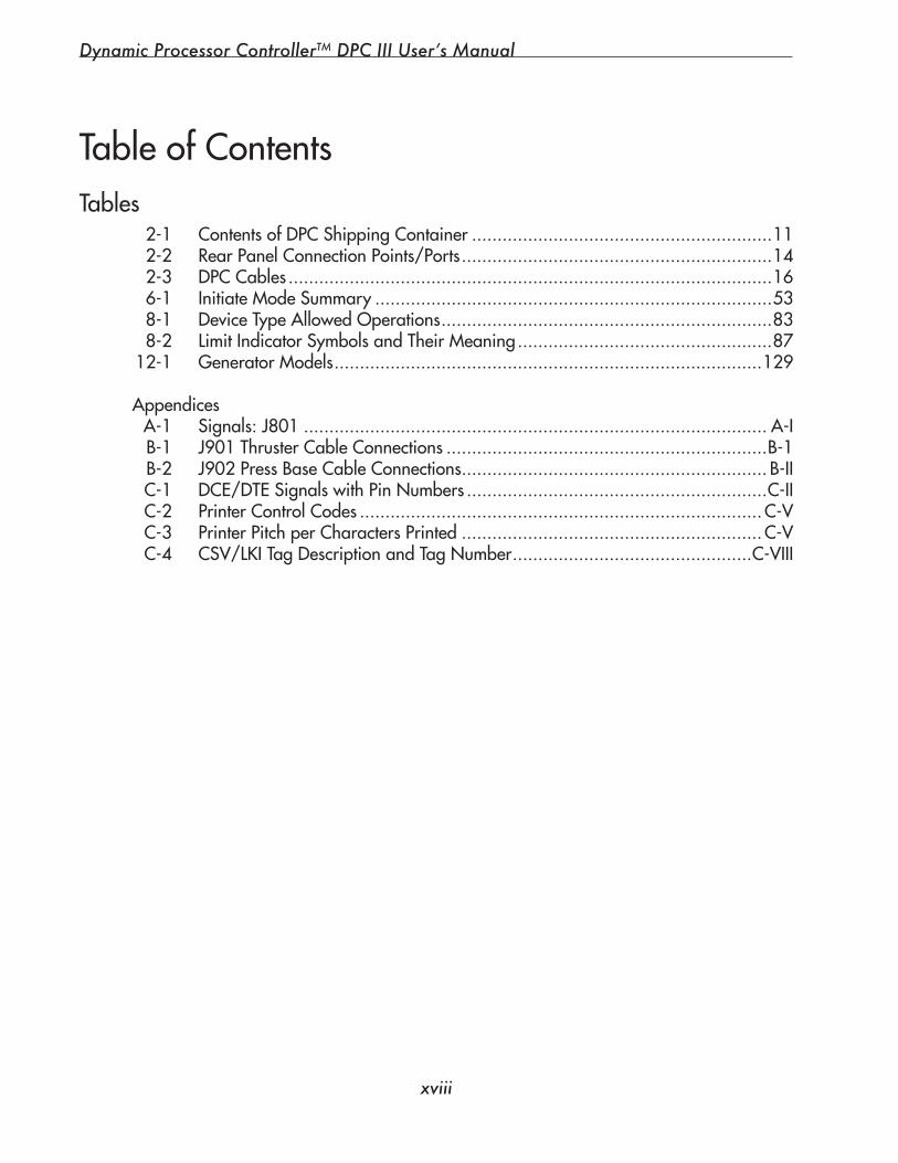
A-1 I/OJumperBlockLocation...................................................................... A-VI A-2 DPCIIIInputConfiguration1................................................................. A-VIII A-3 DPCIIIInputConfiguration2................................................................... A-IX A-4 DPCIIIOutputConfiguration1.................................................................. A-X A-5 DPCIIIOutputConfiguration2................................................................. A-XI A-6 DPCIIIOutputConfiguration3.................................................................A-XII A-7 DPCIIIInputforEmergencyStopSwitch..................................................A-XIII A-8 PLCInputforThrusterTop-of-StrokeSwitch.............................................. A-XIV C-1 DCEtoDTESerialConnections.................................................................C-III C-2 ParallelandSerialInterfaceConnectors.................................................... C-IV C-3 ASCIIOutputFormat............................................................................... C-VI C-4 1-2-3OutputFormat.............................................................................. C-VII C-5 CSVOutputformat................................................................................C-VIII C-6 ZontecOutputFormat............................................................................. C-IX
TableofContentsFigures–Appendices
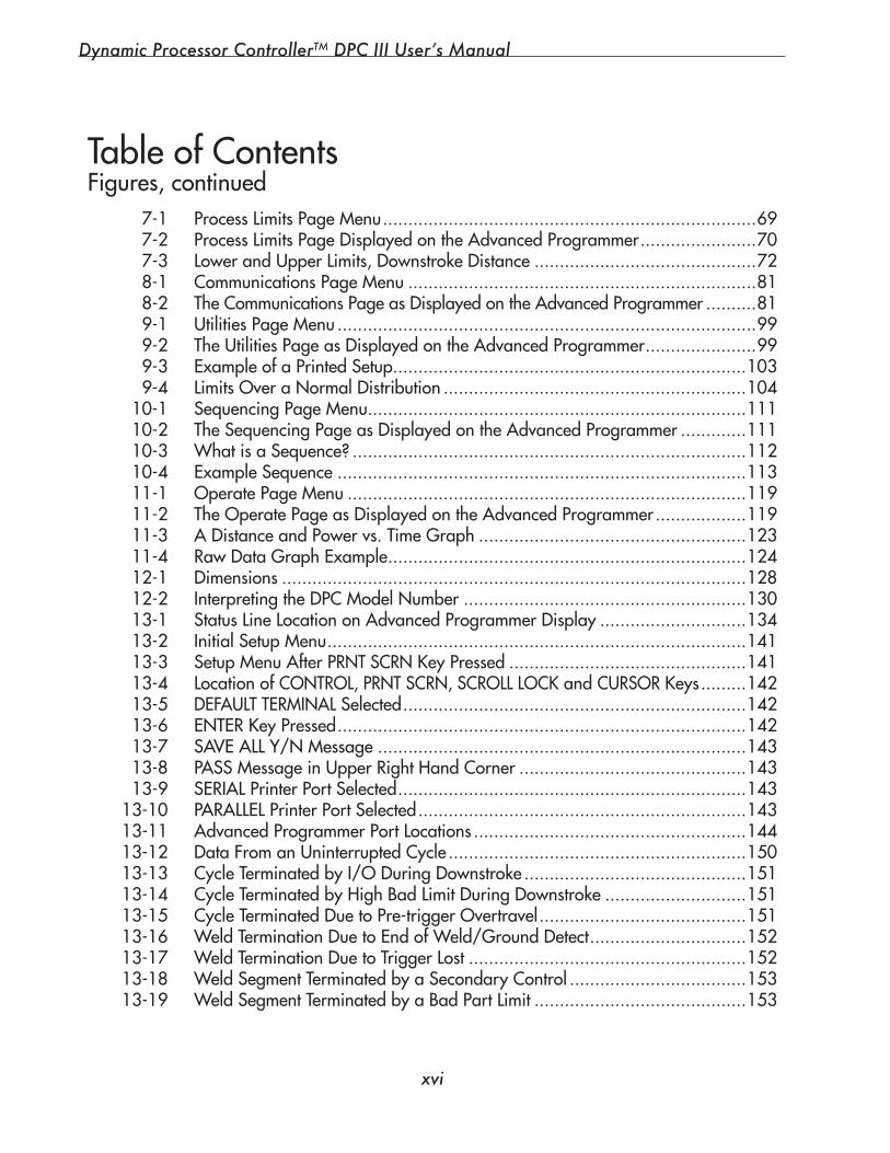
7-1 ProcessLimitsPageMenu..........................................................................69 7-2 ProcessLimitsPageDisplayedontheAdvancedProgrammer.......................70 7-3 LowerandUpperLimits,DownstrokeDistance............................................72 8-1 CommunicationsPageMenu.....................................................................81 8-2 TheCommunicationsPageasDisplayedontheAdvancedProgrammer..........81 9-1 UtilitiesPageMenu...................................................................................99 9-2 TheUtilitiesPageasDisplayedontheAdvancedProgrammer......................99 9-3 ExampleofaPrintedSetup......................................................................103 9-4 LimitsOveraNormalDistribution............................................................104 10-1 SequencingPageMenu...........................................................................111 10-2 TheSequencingPageasDisplayedontheAdvancedProgrammer.............111 10-3 WhatisaSequence?..............................................................................112 10-4 ExampleSequence.................................................................................113 11-1 OperatePageMenu...............................................................................119 11-2 TheOperatePageasDisplayedontheAdvancedProgrammer..................119 11-3 ADistanceandPowervs.TimeGraph.....................................................123 11-4 RawDataGraphExample.......................................................................124 12-1 Dimensions............................................................................................128 12-2 InterpretingtheDPCModelNumber........................................................130 13-1 StatusLineLocationonAdvancedProgrammerDisplay.............................134 13-2 InitialSetupMenu...................................................................................141 13-3 SetupMenuAfterPRNTSCRNKeyPressed...............................................141 13-4 LocationofCONTROL,PRNTSCRN,SCROLLLOCKandCURSORKeys.........142 13-5 DEFAULTTERMINALSelected....................................................................142 13-6 ENTERKeyPressed.................................................................................142 13-7 SAVEALLY/NMessage.........................................................................143 13-8 PASSMessageinUpperRightHandCorner.............................................143 13-9 SERIALPrinterPortSelected.....................................................................143 13-10 PARALLELPrinterPortSelected.................................................................143 13-11 AdvancedProgrammerPortLocations......................................................144 13-12 DataFromanUninterruptedCycle...........................................................150 13-13 CycleTerminatedbyI/ODuringDownstroke............................................151 13-14 CycleTerminatedbyHighBadLimitDuringDownstroke............................151 13-15 CycleTerminatedDuetoPre-triggerOvertravel.........................................151 13-16 WeldTerminationDuetoEndofWeld/GroundDetect...............................152 13-17 WeldTerminationDuetoTriggerLost.......................................................152 13-18 WeldSegmentTerminatedbyaSecondaryControl...................................153 13-19 WeldSegmentTerminatedbyaBadPartLimit..........................................153
TableofContentsFigures,continued
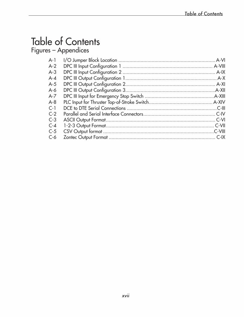
Table of Contents
xvii
A-1 I/OJumperBlockLocation...................................................................... A-VI A-2 DPCIIIInputConfiguration1................................................................. A-VIII A-3 DPCIIIInputConfiguration2................................................................... A-IX A-4 DPCIIIOutputConfiguration1.................................................................. A-X A-5 DPCIIIOutputConfiguration2................................................................. A-XI A-6 DPCIIIOutputConfiguration3.................................................................A-XII A-7 DPCIIIInputforEmergencyStopSwitch..................................................A-XIII A-8 PLCInputforThrusterTop-of-StrokeSwitch.............................................. A-XIV C-1 DCEtoDTESerialConnections.................................................................C-III C-2 ParallelandSerialInterfaceConnectors.................................................... C-IV C-3 ASCIIOutputFormat............................................................................... C-VI C-4 1-2-3OutputFormat.............................................................................. C-VII C-5 CSVOutputformat................................................................................C-VIII C-6 ZontecOutputFormat............................................................................. C-IX
TableofContentsFigures–Appendices
7-1 ProcessLimitsPageMenu..........................................................................69 7-2 ProcessLimitsPageDisplayedontheAdvancedProgrammer.......................70 7-3 LowerandUpperLimits,DownstrokeDistance............................................72 8-1 CommunicationsPageMenu.....................................................................81 8-2 TheCommunicationsPageasDisplayedontheAdvancedProgrammer..........81 9-1 UtilitiesPageMenu...................................................................................99 9-2 TheUtilitiesPageasDisplayedontheAdvancedProgrammer......................99 9-3 ExampleofaPrintedSetup......................................................................103 9-4 LimitsOveraNormalDistribution............................................................104 10-1 SequencingPageMenu...........................................................................111 10-2 TheSequencingPageasDisplayedontheAdvancedProgrammer.............111 10-3 WhatisaSequence?..............................................................................112 10-4 ExampleSequence.................................................................................113 11-1 OperatePageMenu...............................................................................119 11-2 TheOperatePageasDisplayedontheAdvancedProgrammer..................119 11-3 ADistanceandPowervs.TimeGraph.....................................................123 11-4 RawDataGraphExample.......................................................................124 12-1 Dimensions............................................................................................128 12-2 InterpretingtheDPCModelNumber........................................................130 13-1 StatusLineLocationonAdvancedProgrammerDisplay.............................134 13-2 InitialSetupMenu...................................................................................141 13-3 SetupMenuAfterPRNTSCRNKeyPressed...............................................141 13-4 LocationofCONTROL,PRNTSCRN,SCROLLLOCKandCURSORKeys.........142 13-5 DEFAULTTERMINALSelected....................................................................142 13-6 ENTERKeyPressed.................................................................................142 13-7 SAVEALLY/NMessage.........................................................................143 13-8 PASSMessageinUpperRightHandCorner.............................................143 13-9 SERIALPrinterPortSelected.....................................................................143 13-10 PARALLELPrinterPortSelected.................................................................143 13-11 AdvancedProgrammerPortLocations......................................................144 13-12 DataFromanUninterruptedCycle...........................................................150 13-13 CycleTerminatedbyI/ODuringDownstroke............................................151 13-14 CycleTerminatedbyHighBadLimitDuringDownstroke............................151 13-15 CycleTerminatedDuetoPre-triggerOvertravel.........................................151 13-16 WeldTerminationDuetoEndofWeld/GroundDetect...............................152 13-17 WeldTerminationDuetoTriggerLost.......................................................152 13-18 WeldSegmentTerminatedbyaSecondaryControl...................................153 13-19 WeldSegmentTerminatedbyaBadPartLimit..........................................153
TableofContentsFigures,continued
Dynamic Processor ControllerTM DPC III User’s Manual
xviii
Tables 2-1 ContentsofDPCShippingContainer...........................................................11 2-2 RearPanelConnectionPoints/Ports.............................................................14 2-3 DPCCables...............................................................................................16 6-1 InitiateModeSummary..............................................................................53 8-1 DeviceTypeAllowedOperations.................................................................83 8-2 LimitIndicatorSymbolsandTheirMeaning..................................................8712-1 GeneratorModels....................................................................................129Appendices A-1 Signals:J801........................................................................................... A-I B-1 J901ThrusterCableConnections...............................................................B-1 B-2 J902PressBaseCableConnections............................................................ B-II C-1 DCE/DTESignalswithPinNumbers...........................................................C-II C-2 PrinterControlCodes...............................................................................C-V C-3 PrinterPitchperCharactersPrinted...........................................................C-V C-4 CSV/LKITagDescriptionandTagNumber...............................................C-VIII
TableofContents

SECTION 1
Introduction and Safety
• This section gives a general introduction to the DPC III, and dealswithsafetyconsiderations.
Dukane Corporation

Dynamic Processor ControllerTM DPC III Plus User’s Manual
This page intentionally left blank
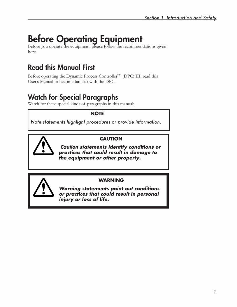
Section 1 Introduction and Safety
�
Before Operating EquipmentBeforeyouoperatetheequipment,pleasefollowtherecommendationsgivenhere.
Read this Manual FirstBefore operating the Dynamic Process ControllerTM (DPC) III, read this User’sManualtobecomefamiliarwiththeDPC.
Watch for Special ParagraphsWatchforthesespecialkindsof paragraphsinthismanual:
NOTE
Note statements highlight procedures or provide information.
CAUTION
Caution statements identify conditions or practices that could result in damage to the equipment or other property.
WARNING
Warning statements point out conditions or practices that could result in personal injury or loss of life.
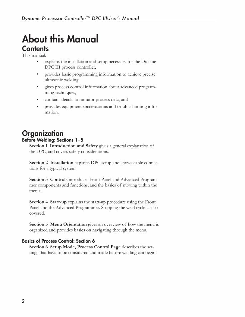
Dynamic Processor ControllerTM DPC IIIUser’s Manual
�
About this ManualContentsThismanual: • explains the installation and setup necessary for the Dukane
DPC III process controller, • provides basic programming information to achieve precise
ultrasonicwelding, • gives process control information about advanced program-
ming techniques, • contains details to monitor process data, and • providesequipmentspecificationsandtroubleshootinginfor-
mation.
OrganizationBefore Welding: Sections 1–5
Section 1 Introduction and Safety gives a general explanation of the DPC, and covers safety considerations.
Section 2 InstallationexplainsDPCsetupandshowscableconnec-tions for a typical system.
Section 3 Controls introduces Front Panel and Advanced Program-mercomponentsandfunctions,andthebasicsof movingwithinthemenus.
Section 4 Start-up explains the start-up procedure using the Front PanelandtheAdvancedProgrammer.Stoppingtheweldcycleisalsocovered.
Section 5 Menu Orientation givesanoverviewof howthemenuisorganized and provides basics on navigating through the menu.
Basics of Process Control: Section 6Section 6 Setup Mode, Process Control Page describes the set-tingsthathavetobeconsideredandmadebeforeweldingcanbegin.
Section 1 Introduction and Safety
�
Organization, continued
.
Beyond the Basics of Process Control: Sections 7-10Section 7 Setup Mode, Process Limits Page describes process characteristicsandshowshowtoestablishlimitstodefinebadandsuspect parts.
Section 8 Setup Mode, Communications Page explainshowtocommunicatewithexternaldevicesincludingsetupinformationallow-ing part sampling and graphing.
Section 9 Setup Mode, Utilities Page gives information on using the setup management tools and diagnostic features this menu pro-vides. Section 10 Setup Mode, Sequencing Page describeshowtheDPCcanbeusedforjobsthatneedmultipleweldsinasinglesetup.
Section 11 Operate Mode, Operate Page describeswaystoaccom-plish real-time monitoring of the process control functions.
Section 12 Specifications isasummaryof theDPCpowerandspacerequirements.
Section 13 Care and Troubleshooting describes equipment care and provideselementarydiagnosticinformationincludingerrorandwarn-ing messages.
Section 14 Contacting Dukane gives information on support from theDukaneUltrasonicsfactoryteam,andprovideswarrantyinforma-tion.
Section 15 Appendices contain technical reference data.
The Index has page references for terms the manual uses.
Monitoring the Welding Process: Section 11
Supporting Information: Sections 12 -16
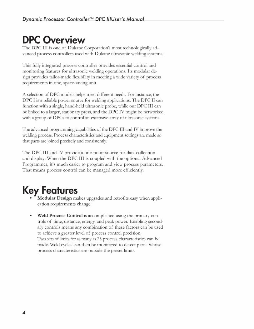
Dynamic Processor ControllerTM DPC IIIUser’s Manual
�
DPC OverviewThe DPC III is one of Dukane Corporation’s most technologically ad-vancedprocesscontrollersusedwithDukaneultrasonicweldingsystems.
This fully integrated process controller provides essential control and monitoringfeaturesforultrasonicweldingoperations.Itsmodularde-signprovidestailor-madeflexibilityinmeetingawidevarietyof processrequirements in one, space-saving unit.
A selection of DPC models helps meet different needs. For instance, the DPCIisareliablepowersourceforweldingapplications.TheDPCIIcanfunctionwithasingle,hand-heldultrasonicprobe,whileourDPCIIIcanbelinkedtoalarger,stationarypress,andtheDPCIVmightbenetworkedwithagroupofDPCstocontrolanextensivearrayofultrasonicsystems.
The advanced programming capabilities of the DPC III and IV improve the weldingprocess.Processcharacteristicsandequipmentsettingsaremadesothat parts are joined precisely and consistently.
The DPC III and IV provide a one-point source for data collection anddisplay.WhentheDPCIIIiscoupledwiththeoptionalAdvancedProgrammer,it’smucheasiertoprogramandviewprocessparameters.Thatmeansprocesscontrolcanbemanagedmoreefficiently.
Key Features• Modular Designmakesupgradesandretrofitseasywhenappli-
cation requirements change.
• Weld Process Control is accomplished using the primary con-trolsof time,distance,energy,andpeakpower.Enablingsecond-ary controls means any combination of these factors can be used to achieve a greater level of process control precision.
Twosetsoflimitsforasmanyas25processcharacteristicscanbemade.Weldcyclescanthenbemonitoredtodetectpartswhoseprocess characteristics are outside the preset limits.
Section 1 Introduction and Safety
�
amplitude regardless of line voltage deviation.*
• Load Regulation provides constant amplitude automatically regardlessof load(powerdraw).*
• Power Factor Correction (optional) means that the DPC wouldbecapableof reducingitselectricalpowerconsump-tion by approximately 25%.
• Worldwide Auto-Ranging Universal Voltage Input means thattheDPCwilloperateanywhereintheworld.Nomanualpoweradjustmentsareneeded.
* Within specified ranges.
• Progressive PressureforholdingandweldingareavailableincombinationwiththeDukanethrusterthatincorporatesdual pressure capability.
• Interface Versatility means that in addition to the DPC’s ownfrontpaneldisplay,itcanconnectwiththeAdvancedProgrammer display, automation equipment, printer, and computer.TheDPCwillalsooutputdataforadedicatedstatistical process control (SPC) system.
• Automatic Setup Changeisusedwhenpartsrequiremorethan one assembly operation and more than one set of pro-cess parameters.
• Pulse Width Modulation is Dukane’s patented circuitry giv-ingtheDPCpowersupplytheabilitytoefficientlychangethevoltage sent to the transducer.
• Auto-Trac Tuning automatically tracks the resonant fre-quency of the acoustic stack (horn, booster, transducer), and adjusts the generator output frequency to match it.*
• Line Voltage Regulation automatically maintains constant
Key Features, continued

Dynamic Processor ControllerTM DPC IIIUser’s Manual
�
NOTE
These recommendations apply to the welding system, that is, the DPC, and the other components associated with join-ing plastic and/or metal parts ultrasonically.
Proper Installation - Operate system components only after they are properly installed.
No Unauthorized Modifications - Do not modify your system in any wayunlessauthorizedtodosobyDukaneCorporation.Unauthorizedmodificationscouldcauseequipmentdamageand/orinjurytotheopera-tor.Inaddition,unauthorizedmodificationswillvoidequipmentwar-ranty.
Keep the Cover On - Do not remove any equipment cover unless di-rected to do so by Dukane Corporation.
Grounded Electrical Power -Operatethisequipmentonlywithagrounded electrical connection. (See Electrical Safety Grounding Instructions on the next page.)
Comply with Regulations - You may be required to add accessories to bringthesystemintocompliancewithapplicableOSHAregulationsformachine guarding and noise exposure.
CAUTION Parts being joined ultrasonically some-times vibrate at audible frequencies. Wear ear protectors to reduce annoy-ing or uncomfortable sounds. In addi-
tion, ultrasound baffles, sound enclosures, or ma-terials that absorb sound may be located to sur-round the system.
Health and Safety RecommendationsPleaseobservethesehealthandsafetyrecommendationsforsafe,effi-cient, and injury-free operation of your equipment.
“System” in this manual refers to a complete group of components associ-atedwiththeweldingofplasticormetalparts,alsoknownasanultrasonicassembly system. A typical system consists of a generator and/or ultrasonic processcontroller,athrusterorpress,switches,controls,cables,transducer,booster,horn,andfixture.

Section 1 Introduction and Safety
�
Special Health Notice – PlasticsBeforeusinganyDukaneultrasonicsystem,becomefamiliarwithOSHA regulations from the U.S. Department of Labor about the particular type of plastic(s) you are using.
When plastic materials are being processed, they may emit fumes and/or gases that could be hazardous.
Makesurethereisproperventilationwhenevertheseplasticsareprocessed.
Electrical Safety Grounding InstructionsForsafety,thepowercordsusedonallDukaneproductshaveathree-prong, grounding-type plug.
If you must use a two-prong electrical receptacle, we strongly recommend that you replace it with a properly grounded three-prong type. Have a
qualified electrician replace it following the Na-tional Electric Code and any local codes and ordi-nances that apply. See Figures 1-1 and 1-2.
If there is any question about the grounding of your receptacle, have it checked by a qualified electrician.
Do not cut off the power cord grounding prong or alter the plug in any way.Extension Cord: If an extension cord is needed, use a three-wire cord that’s in good condition. The cord should be large enough to do the job safely. It, too, must be plugged into a grounded receptacle. Do not use a two-wire extension cord with this product.
Approved 2 pole, 3 wire grounding receptacle BRYANT No. 5261 or equivalent to NEMA 5-15R OR 5-20R
Figure1-1 Example of ��0 V, Grounded, 3-Prong Receptacle
Approved 2 pole, 3 wire grounding receptacle HUBBELL No. 5652 or equivalent to NEMA 6-15R OR 6-20R
Figure1-2 Example of ��0 V, Grounded, 3-Prong Receptacle
CAUTION
CAUTION
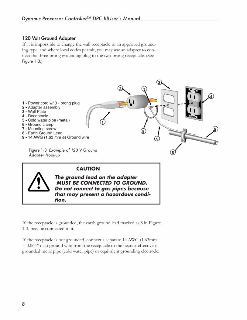
Dynamic Processor ControllerTM DPC IIIUser’s Manual
�
120 Volt Ground AdapterIf itisimpossibletochangethewallreceptacletoanapprovedground-ing-type,andwherelocalcodespermit,youmayuseanadaptertocon-nectthethree-pronggroundingplugtothetwo-prongreceptacle.(See Figure1-3.)
CAUTION
The ground lead on the adapter MUST BE CONNECTED TO GROUND. Do not connect to gas pipes because that may present a hazardous condi-tion.
If the receptacle is grounded, the earth ground lead marked as 8 in Figure 1-3, may be connected to it.
If the receptacle is not grounded, connect a separate 14 AWG (1.63mm =0.064’’dia.)groundwirefromthereceptacletothenearesteffectivelygroundedmetalpipe(coldwaterpipe)orequivalentgroundingelectrode.
1
2
4
3
5
6
7
8
9
1 - Power cord w/ 3 - prong plug2 - Adapter assembly3 - Wall Plate4 - Receptacle5 - Cold water pipe (metal)6 - Ground clamp7 - Mounting screw8 - Earth Ground Lead9 - 14 AWG (1.63 mm ø) Ground wire
Figure1-3Example of 120 V Ground Adapter Hookup
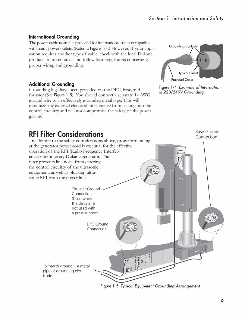
Section 1 Introduction and Safety
�
International GroundingThepowercablenormallyprovidedforinternationaluseiscompatiblewithmanypoweroutlets.(RefertoFigure1-4.)However,if yourappli-cationrequiresanothertypeof cable,checkwiththelocalDukaneproductsrepresentative,andfollowlocalregulationsconcerningproperwiringandgrounding.
Additional GroundingGrounding lugs have been provided on the DPC, base, and thruster (See Figure1-5). You should connect a separate 14 AWG groundwiretoaneffectivelygroundedmetalpipe.Thiswillminimize any external electrical interference from leaking into the controlcircuitryandwillnotcompromisethesafetyof thepowerground.
RFI Filter Considerations In addition to the safety considerations above, proper grounding atthegeneratorpowercordisessentialfortheeffectiveoperation of the RFI (Radio Frequency Interfer-ence)filterineveryDukanegenerator.Thefilterpreventslinenoisefromenteringthe control circuitry of the ultrasonic equipment,aswellasblockingultra-sonicRFIfromthepowerline.
Figure1-5 Typical Equipment Grounding Arrangement
Figure1-4 Example of Internation-al 220/240V Grounding
GroundingContacts
TypicalOutlet
ProvidedCable
DPC Ground Connection
To “earth ground”, a metal pipe or grounding elec-trode.
Thruster Ground Connection (Used when the thruster is not used with a press support
Base GroundConnection

Dynamic Processor ControllerTM DPC III Plus User’s Manual
�0
This page intentionally left blank

SECTION 2
Installation• Thissectiondealswithbasicinstallation:locatingand
cabling the .
Dukane Corporation

Dynamic Processor ControllerTM DPC III Plus User’s Manual
This page intentionally left blank

Section � Installation
��
UnpackingCarefully open the shipping container, and make sure it has theitemsshowninTable2-1.
Quantity Item Part Number1 DPC III **
1 DPC III User’s
Manual
403-541-04
AC power cord and cables as specified. See your packing
list. Compare with Table 2-3.
Table2-1 Contents of DPC Shipping Container
** See Section 12, Specifications, for an explanation of the DPC part number.
DPC PlacementPlacementof theDPCdependsonwhattypeitis,bench-top or rack-mounted.
Benchtop PlacetheDPCneartheultrasonicpressonaflatsurfacewithitsfrontpaneleasilyaccessible.Makecertaintheplacementandcablingdonotinterferewithpressopera-tion.
Allow5inches(13cm)attherearof theDPCforcableclearance.Allow6inches(15cm)of spaceoneithersideof the DPC for air circulation. Refer toFigure2-1.
Figure2-1 Placing a Benchtop DPC Continued
2200
STATUS
FAULT
ON LINE
INPUT TEST
OVERTEMP
OVERLOAD
OFF LINE
0 20 40 60 80 100PERCENTAGE OF AVAILABLE POWER
SYSTEM POWER OUTPUT
ONLINE
TESTOFFLINE
Allow space, 5 inches (12 cm) for cables
Allow space for ventilation,
4 inches (10 cm) on each side.
Dynamic Process Controller DPC III
CANCEL ENTER
SETUP
OPERATE
TM
NOTEQuestions or problems? Call your sales representa-tive or the Sales Depart-ment at Dukane Corpo -ration Headquarters for most concerns. If reporting damage, contact the car-rier first. Save all shipping containers and packing materials so they can be inspected in processing any claims that may arise. For additional help contact Dukane Support/Service. See Section �� for contact information.
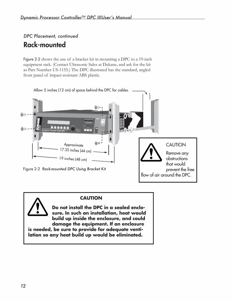
Dynamic Processor ControllerTM DPC IIIUser’s Manual
��
Figure2-2showstheuseof abracketkitinmountingaDPCtoa19-inchequipment rack. (Contact Ultrasonic Sales at Dukane, and ask for the kit as Part Number US-1155.) The DPC illustrated has the standard, angled front panel of impact-resistant ABS plastic.
Figure2-2 Rack-mounted DPC Using Bracket Kit
DPC Placement, continued
Rack-mounted22
00 STATUS
FAULT
ON LINE
INPUT TEST
OVERTEMP
OVERLOAD
OFF LINE
0 20 40 60 80 100PERCENTAGE OF AVAILABLE POWER
SYSTEM POWER OUTPUT
ONLINE TEST OFF
LINE
Allow 5 inches (12 cm) of space behind the DPC for cables.
Approximate17.35 inches (44 cm)
19 inches (48 cm)
Dynamic Process Controller DPC IIITM
CANCELENTER OPERATE
SETUP
Removeanyobstructionsthatwouldpreventthefree
flowofairaroundtheDPC.
CAUTION
DonotinstalltheDPCinasealedenclo-sure.Insuchaninstallation,heatwouldbuildupinsidetheenclosure,andcoulddamagetheequipment.Ifanenclosure
isneeded,besuretoprovideforadequateventi-lationsoanyheatbuildupwouldbeeliminated.
CAUTION
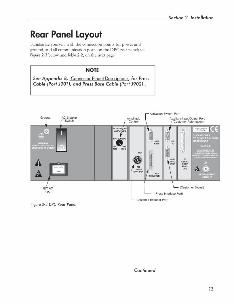
Section � Installation
��
Rear Panel Layout Familiarizeyourself withtheconnectionpointsforpowerandground, and all communication ports on the DPC rear panel; see Figure2-3belowandTable2-2, on the next page.
NOTE
See Appendix B, ConnectorPinoutDescriptions, for Press Cable (Port J901), and Press Base Cable (Port J902) .
Figure2-3 DPC Rear Panel
Continued
WARNINGPOWER LINE MUST BEGROUNDED AT OUTLET
– WARNING! –
POWER LINE MUST BEGROUNDED AT OUTLET.
REMOVE ALL POWER BEFOREREMOVING COVER OR CONNECTING
OR DISCONNECTING CABLES.
J1
ULTRASOUNDOUTPUT
LINEARENCODER
J901THRUSTER
J902BASE
J801I/O
J802AUTOSTOP
J3SERIALPORT
RS-232DCE
40%MIN
100%MAX
60% 80%
ULTRASOUNDAMPLITUDE
DUKANE CORPST. CHARLES, IL 60174MADE IN USA
SERIAL NUMBER US 123456
O
I
IEC ACInput
Ground
Activation Switch Port
Auxiliary Input/Output Port
(Press Interface Port)
AC BreakerSwitch
(Customer Automation)
(Customer Signal)
(Distance Encoder Port)
AmplitudeControl
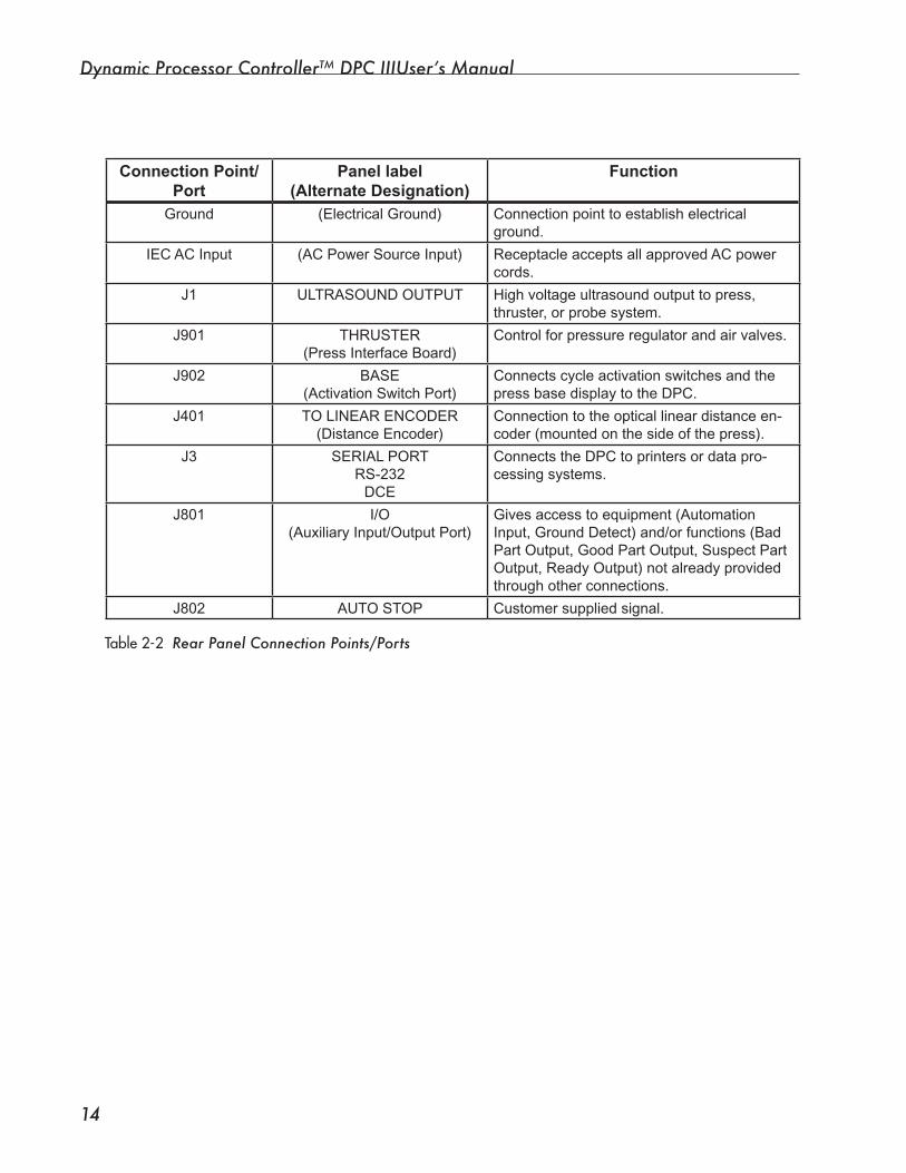
Dynamic Processor ControllerTM DPC IIIUser’s Manual
��
Table2-2 Rear Panel Connection Points/Ports
Connection Point/Port
Panel label(Alternate Designation)
Function
Ground (Electrical Ground) Connection point to establish electrical ground.
IEC AC Input (AC Power Source Input) Receptacle accepts all approved AC power cords.
J1 ULTRASOUND OUTPUT High voltage ultrasound output to press, thruster, or probe system.
J901 THRUSTER(Press Interface Board)
Control for pressure regulator and air valves.
J902 BASE(Activation Switch Port)
Connects cycle activation switches and the press base display to the DPC.
J401 TO LINEAR ENCODER(Distance Encoder)
Connection to the optical linear distance en-coder (mounted on the side of the press).
J3 SERIAL PORTRS-232
DCE
Connects the DPC to printers or data pro-cessing systems.
J801 I/O(Auxiliary Input/Output Port)
Gives access to equipment (Automation Input, Ground Detect) and/or functions (Bad Part Output, Good Part Output, Suspect Part Output, Ready Output) not already provided through other connections.
J802 AUTO STOP Customer supplied signal.
Section � Installation
��
CAUTIONThe power cord is equipped with a three-prong, gounded-type plug for your safety. Whenever a two-slot re-ceptacle is encountered, we strongly
recommend that it is replaced with a prop-erly grounded three-lead receptacle. Have a qualified electrician do the replacement in ac-cordance with the National Elecrical Code and local codes and ordinances.
DO NOT cut off the power cord grounding prong or alter the plug in any way.
Ground the SystemMake sure the system is properly grounded.
Is the system properly grounded? Before proceeding, make sure you have fol-lowed the instructions of Section 1 relat-ing to electrical grounding.
Connect the Cables
Make sure electrical power is off before connecting or disconnecting cables to the DPC. Put both the front panel ON/OFF
switch and the rear panel AC breaker switch in the OFF position whenever cables are connected to or disconnected from the DPC.
Complete the cable connections for your system usingFigures2-4 through 2-8 and Table2-3 as guides.Thepowercableisthelastonetobeconnected,butdonotturnonthepowertotheDPCasyet.
Systems may or may not have cables as shown. Com-pare your equipment order with the cables that were
NOTE
CAUTION
CAUTION
Continued
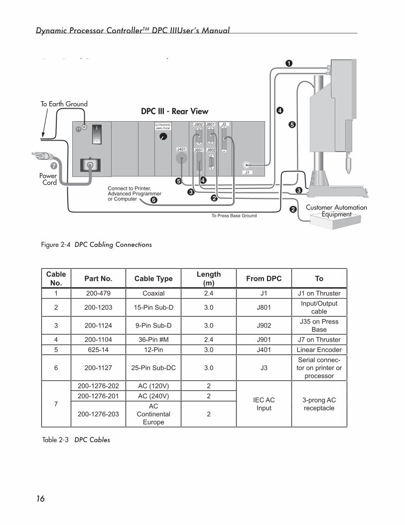
Dynamic Processor ControllerTM DPC IIIUser’s Manual
��
Figure2-4 DPC Cabling Connections
Table2-3DPC Cables
Rear Panel Connections, continued
DPC III - Rear View
J1
I
O
To Earth Ground
PowerCord
To Press Base Ground
Customer AutomationEquipment
Customer AutomationEquipment
J401
ULTRASONICAMPLITUDE
5
5
3
J902
J901
4
7
4
1
3
J801
J802
2
2
J3
Connect to Printer,Advanced Programmeror Computer 6
Cable No.
Part No. Cable TypeLength
(m)From DPC To
1 200-479 Coaxial 2.4 J1 J1 on Thruster
2 200-1203 15-Pin Sub-D 3.0 J801Input/Output
cable
3 200-1124 9-Pin Sub-D 3.0 J902J35 on Press
Base
4 200-1104 36-Pin #M 2.4 J901 J7 on Thruster
5 625-14 12-Pin 3.0 J401 Linear Encoder
6 200-1127 25-Pin Sub-DC 3.0 J3Serial connec-tor on printer or
processor
7
200-1276-202 AC (120V) 2
IEC ACInput
3-prong ACreceptacle
200-1276-201 AC (240V) 2
200-1276-203AC
ContinentalEurope
2
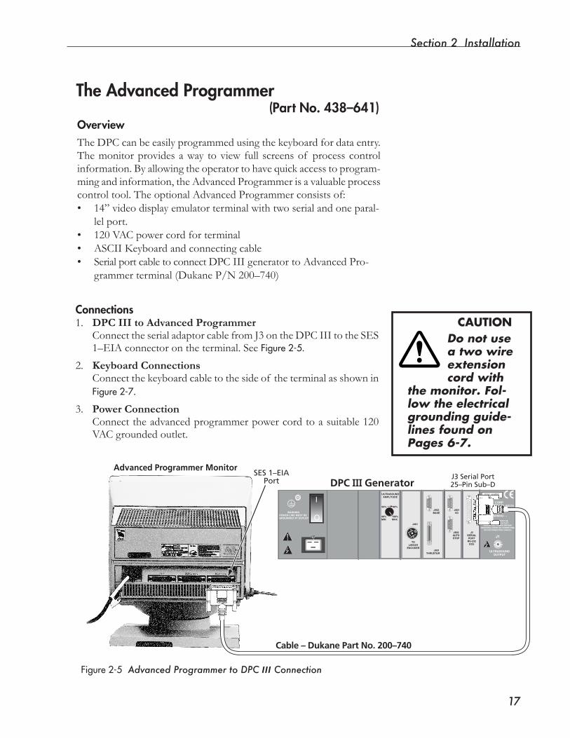
Section � Installation
��
The Advanced Programmer (Part No. 438–641)
Figure2-5 Advanced Programmer to DPC III Connection
Connections1. DPC III to Advanced Programmer Connect the serial adaptor cable from J3 on the DPC III to the SES
1–EIA connector on the terminal. See Figure2-5.
2. Keyboard Connections Connectthekeyboardcabletothesideof theterminalasshownin
Figure2-7.
3. Power Connection Connecttheadvancedprogrammerpowercordtoasuitable120
VAC grounded outlet.
OverviewThe DPC can be easily programmed using the keyboard for data entry. Themonitorprovidesaway toviewfull screensof processcontrolinformation.Byallowingtheoperatortohavequickaccesstoprogram-ming and information, the Advanced Programmer is a valuable process controltool.TheoptionalAdvancedProgrammerconsistsof:• 14”videodisplayemulatorterminalwithtwoserialandoneparal-
lel port.• 120VACpowercordforterminal• ASCII Keyboard and connecting cable• Serial port cable to connect DPC III generator to Advanced Pro-
grammerterminal(DukaneP/N200–740)
WARNINGPOWER LINE MUST BEGROUNDED AT OUTLET
– WARNING! –
POWER LINE MUST BEGROUNDED AT OUTLET.
REMOVE ALL POWER BEFOREREMOVING COVER OR CONNECTING
OR DISCONNECTING CABLES.
J1
ULTRASOUNDOUTPUT
TOLINEAR
ENCODER
J401
J901THRUSTER
J902BASE
J801I/O
J802AUTOSTOP
J3SERIALPORT
RS-232DCE
40%MIN
100%MAX
60% 80%
ULTRASOUNDAMPLITUDE
DUKANE CORPST. CHARLES, IL 60174MADE IN USA
SERIAL NUMBER US 123456
O
I
Cable – Dukane Part No. 200–740
Advanced Programmer MonitorSES 1–EIA
Port J3 Serial Port25–Pin Sub–DDPC III Generator
CAUTIONDo not use a two wire extension cord with
the monitor. Fol-low the electrical grounding guide-lines found on Pages 6-7.
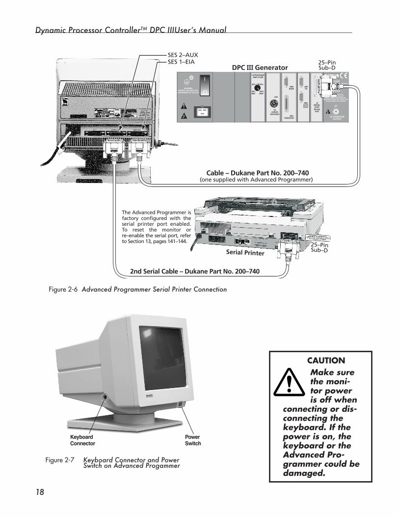
Dynamic Processor ControllerTM DPC IIIUser’s Manual
��
Figure2-7 Keyboard Connector and Power Switch on Advanced Progammer
WARNINGPOWER LINE MUST BEGROUNDED AT OUTLET
– WARNING! –
POWER LINE MUST BEGROUNDED AT OUTLET.
REMOVE ALL POWER BEFOREREMOVING COVER OR CONNECTING
OR DISCONNECTING CABLES.
J1
ULTRASOUNDOUTPUT
TOLINEAR
ENCODER
J401
J901THRUSTER
J902BASE
J801I/O
J802AUTOSTOP
J3SERIALPORT
RS-232DCE
40%MIN
100%MAX
60% 80%
ULTRASOUNDAMPLITUDE
DUKANE CORPST. CHARLES, IL 60174MADE IN USA
SERIAL NUMBER US 123456
O
I
Serial Printer
2nd Serial Cable – Dukane Part No. 200–740
Cable – Dukane Part No. 200–740
SES 1–EIASES 2–AUX
25–PinSub–D
25–PinSub–DDPC III Generator
The Advanced Programmer is factory configured with the serial printer port enabled. To reset the monitor or re–enable the serial port, refer to Section 13, pages 141–144.
(one supplied with Advanced Programmer)
CAUTIONMake sure the moni-tor power is off when
connecting or dis-connecting the keyboard. If the power is on, the keyboard or the Advanced Pro-grammer could be damaged.
KeyboardConnector
PowerSwitch
Figure2-6 Advanced Programmer Serial Printer Connection
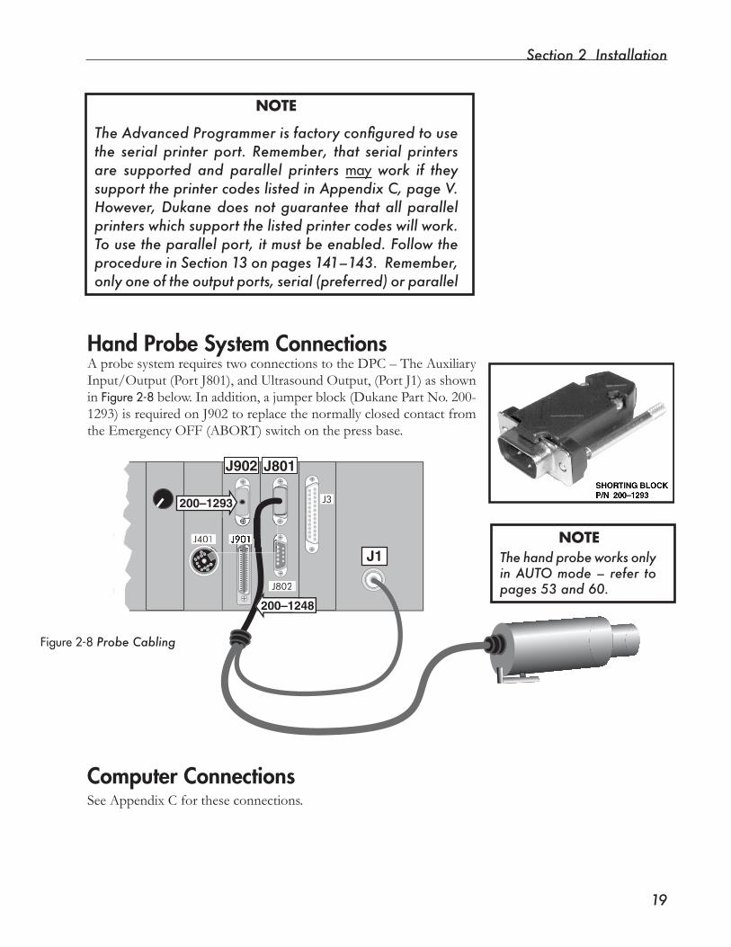
Section � Installation
��
Hand Probe System ConnectionsAprobesystemrequirestwoconnectionstotheDPC–TheAuxiliaryInput/Output(PortJ801),andUltrasoundOutput,(PortJ1)asshownin Figure2-8below.Inaddition,ajumperblock(DukanePartNo.200-1293) is required on J902 to replace the normally closed contact from theEmergencyOFF(ABORT)switchonthepressbase.
Computer ConnectionsSee Appendix C for these connections.
J1
J801J902
J802
J3
J401
200–1248
200–1293
The hand probe works only in AUTO mode – refer to pages 53 and 60.
NOTE
NOTE
The Advanced Programmer is factory configured to use the serial printer port. Remember, that serial printers are supported and parallel printers may work if they support the printer codes listed in Appendix C, page V. However, Dukane does not guarantee that all parallel printers which support the listed printer codes will work. To use the parallel port, it must be enabled. Follow the procedure in Section 13 on pages 141–143. Remember, only one of the output ports, serial (preferred) or parallel
Figure2-8Probe Cabling
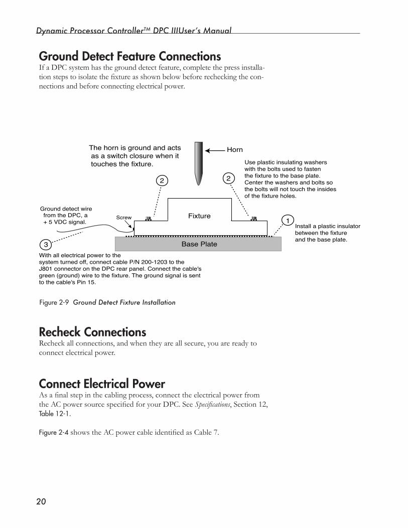
Dynamic Processor ControllerTM DPC IIIUser’s Manual
�0
Ground Detect Feature ConnectionsIf a DPC system has the ground detect feature, complete the press installa-tionstepstoisolatethefixtureasshownbelowbeforerecheckingthecon-nectionsandbeforeconnectingelectricalpower.
Recheck ConnectionsRecheckallconnections,andwhentheyareallsecure,youarereadytoconnectelectricalpower.
Connect Electrical PowerAsafinalstepinthecablingprocess,connecttheelectricalpowerfromtheACpowersourcespecifiedforyourDPC.SeeSpecifications, Section 12, Table12-1.
Figure2-4showstheACpowercableidentifiedasCable7.
Figure2-9 Ground Detect Fixture Installation
Base Plate
Fixturefrom the DPC, a�+ 5 VDC signal.
Ground detect wireScrew
3
2
1
2
The horn is ground and acts � as a switch closure when it � touches the fixture.
� Horn
With all electrical power to the�system turned off, connect cable P/N 200-1203 to the�J801 connector on the DPC rear panel. Connect the cable's�green (ground) wire to the fixture. The ground signal is sent �to the cable's Pin 15.�
Use plastic insulating washers�with the bolts used to fasten�the fixture to the base plate.�Center the washers and bolts so�the bolts will not touch the insides�of the fixture holes.
Install a plastic insulator�between the fixture�and the base plate.

SECTION 3
Controls• Functions of the controls on the DPC III Front Panel,
Rear Panel and the Advanced Programmer are explained.
Dukane Corporation

Dynamic Processor ControllerTM DPC III Plus User’s Manual
This page intentionally left blank
Section � Controls
��
Figure3-1b Front Panel Layout
Front Panel LayoutThe DPCFrontPanelisarrangedintothreesectionsshownbelowinFigure3-1b:
• DPC Display and Keypad,
• Generator Status Panel, and
• ACPower.
Rear Panel ControlThe rear panel has an amplitude adjustment knob for controlling the ultrasound output level. The amplitude may be manually adjusted from40%to100%.Theadjustmentshaftissecuredwithashaft–lockbushing that is vibration and shock resistant to prevent unintentional changes.ThecontrolisshownbelowinFigure3–1a.
GeneratorStatus Panel
AC Power
GreenPower On LED
2200
STATUS
FAULT
ON LINE
INPUT TEST
OVERTEMP
OVERLOAD
OFF LINE
ONLINE TEST OFF
LINE
0 20 40 60 80 100PERCENTAGE OF AVAILABLE POWER
SYSTEM POWER OUTPUT
Dynamic Process Controller
OPERATECANCEL
SETUP
ENTER
S01 PROCESS CONTROL
DPC™ III
DPC Display and Keypad
Figure3-1a Rear Panel Amplitude Control
WARNINGPOWER LINE MUST BEGROUNDED AT OUTLET
TOLINEAR
ENCODER
J401
40%MIN
100%MAX
60% 80%
ULTRASOUNDAMPLITUDE
O
I
AmplitudeControl
Dynamic Processor ControllerTM DPC IIIUser’s Manual
��
Keypad
Thesix-keykeypadisusedtoaccessdata,andtosetupandmodifyweldprocess parameters. The operator can scroll through the various menus, makechangesintheoperatingparameters,andselectspecificoperationsto be monitored.
Front Panel Display and Keypad OverviewDisplay The LCD display has one line displaying as many as 32 alphanumeric characters.Thedisplayallowstheoperatortoselectand/ormodifyallprocessparameters.Inaddition,allerrormessagesandpromptswillap-pear here.
IntheOperatemode,allopenprocesslimitsof thelastweldwillappearhere.
Figure3-2 Keypad Functions
2200
STATUS
FAULT
ON LINE
INPUT TEST
OVERTEMP
OVERLOAD
OFF LINE
ONLINE TEST OFF
LINE
0 20 40 60 80 100PERCENTAGE OF AVAILABLE POWER
SYSTEM POWER OUTPUT
Dynamic Process Controller
OPERATECANCEL
SETUP
ENTER
S01 PROCESS CONTROL
DPC™ III
Press to cancel an operation or amistaken entry.When moving through the menus, itacts as a "back" key to move fromthe current item back to a more general one.
Press to select and enter process and system parameters into setupmemory.When moving through menus,it acts as a "forward" key to move from the current item ahead to amore specific one.
ENTER
CANCELLeft and Right Arrows
Two functions:1. When entering a number, move cursor left or right to the digit to be changed.2. In Operate mode: Each active process parameter of the last weld can be viewed on the display by pressing either the left or right arrow key.
Up and Down ArrowsTwo functions:1. Move up or down in a list to select an item.2. When entering a number, the keys increase or decrease the number indicated by the cursor.
Section � Controls
��
Continued
Keypad DetailsThe CANCEL Key
The CANCELkey performs three functions depending on the system mode, SETUPor OPERATE:
• Menu Navigation,• Canceling an Erroneous Entry, or• Canceling a Print or Display Operation
Menu Navigation
In the SETUP mode, on any page, pressing CANCELhas the effect of movingfromalowerlevelmenuitemtoahigherlevelmenuitem.For example, if INITIATEMODE is displayed on the front panel, press-ing CANCELchanges the display to PROCESSCONTROL.
Theonlyexceptiontothisiswhenanentryhasbeenchanged,butnot entered. A description of pressing CANCELin this case is ex-plainedbelow.
Canceling an Erroneous Entry
If anerrorismadewhenenteringanewvaluefortheFrontPaneldisplay, pressing the CANCELkey removes the erroneous entry, and replacesitwiththeoldvalue.PressingtheCANCELkey again moves from the current menu item to the previous menu item.
Canceling a Print or Display Operation
When sending information to the printer or displaying data from previouswelds,pressingtheCANCELkey cancels the print or display operation.
CANCEL
Dynamic Processor ControllerTM DPC IIIUser’s Manual
��
The ENTER Key
The ENTERkeyperformstwofunctions:• Menu Navigation, and• Setup Selection Entry
Menu Navigation
Pressing the ENTERkeyallowsyoutomovefromahigherlevelmenuitemtoalowerlevelitem.Forexample,if thedisplayisatINITIATEMODE, pressing ENTERcauses the Front Panel display to change from INITIATEMODE to SELECTINITIATEMODE. When changing pages, the ENTERkey operatesdifferentlydependingonwhethertheAdvancedProgrammerisconnected to the system.
WiththeAdvancedProgrammerconnected,whenENTERis pressed the pagedisplaywillchangefromPROCESSCONTROL to COMMUNICATIONS. Thisallowsallpagestobedisplayedinquicksuccessionwithaminimumnumber of keystrokes. To access the menu items of a particular page, press the ENTERkeytwice.
Without the Advanced Programmer in the system, pages are changed withtheFrontPanelkeypad.PresstheENTERkey only once to change from page to page.
Setup Selection Entry
To input an item that has been selected, press the ENTERkeywhenthatentry is complete. The ENTER key must be pressed before the DPC III ac-cepts the entry into memory.
ENTER
NOTEREMINDER - The ENTER key must be pressed to save an item to the program memory.
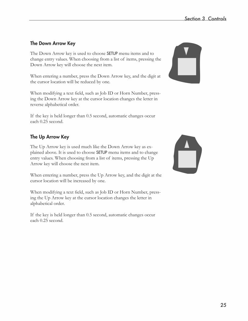
Section � Controls
��
The Down Arrow Key
TheDownArrowkeyisusedtochooseSETUP menu items and to change entry values. When choosing from a list of items, pressing the DownArrowkeywillchoosethenextitem.
Whenenteringanumber,presstheDownArrowkey,andthedigitatthecursorlocationwillbereducedbyone.
Whenmodifyingatextfield,suchasJobIDorHornNumber,press-ingtheDownArrowkeyatthecursorlocationchangestheletterinreverse alphabetical order.
If the key is held longer than 0.5 second, automatic changes occur each 0.25 second.
TheUpArrowkeyisusedmuchliketheDownArrowkeyasex-plained above. It is used to choose SETUP menu items and to change entry values. When choosing from a list of items, pressing the Up Arrowkeywillchoosethenextitem.
Whenenteringanumber,presstheUpArrowkey,andthedigitatthecursorlocationwillbeincreasedbyone.
Whenmodifyingatextfield,suchasJobIDorHornNumber,press-ingtheUpArrowkeyatthecursorlocationchangestheletterinalphabetical order.
If the key is held longer than 0.5 second, automatic changes occur each 0.25 second.
The Up Arrow Key
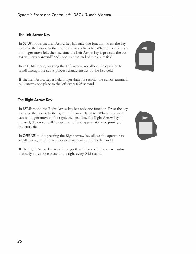
Dynamic Processor ControllerTM DPC IIIUser’s Manual
��
The Left Arrow Key
In SETUPmode,theLeftArrowkeyhasonlyonefunction.Pressthekeyto move the cursor to the left, to the next character. When the cursor can nolongermoveleft,thenexttimetheLeftArrowkeyispressed,thecur-sorwill“wraparound”andappearattheendof theentryfield.
In OPERATEmode,pressingtheLeftArrowkeyallowstheoperatortoscrollthroughtheactiveprocesscharacteristicsof thelastweld.
If theLeftArrowkeyisheldlongerthan0.5second,thecursorautomati-cally moves one place to the left every 0.25 second.
The Right Arrow Key
In SETUPmode,theRightArrowkeyhasonlyonefunction.Pressthekeyto move the cursor to the right, to the next character. When the cursor cannolongermovetotheright,thenexttimetheRightArrowkeyispressed,thecursorwill“wraparound”andappearatthebeginningof theentryfield.
In OPERATEmode,pressingtheRightArrowkeyallowstheoperatortoscrollthroughtheactiveprocesscharacteristicsof thelastweld.
If theRightArrowkeyisheldlongerthan0.5second,thecursorauto-matically moves one place to the right every 0.25 second.
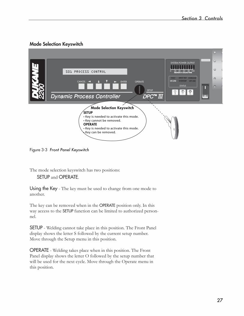
Section � Controls
��
Mode Selection Keyswitch
Themodeselectionkeyswitchhastwopositions:
SETUP and OPERATE.
UsingtheKey - The key must be used to change from one mode to another. ThekeycanberemovedwhenintheOPERATEposition only. In this wayaccesstotheSETUP function can be limited to authorized person-nel.
SETUP - Welding cannot take place in this position. The Front Panel displayshowstheletterSfollowedbythecurrentsetupnumber.Move through the Setup menu in this position.
OPERATE-Weldingtakesplacewheninthisposition.TheFrontPaneldisplayshowstheletterOfollowedbythesetupnumberthatwillbeusedforthenextcycle.MovethroughtheOperatemenuinthis position.
Figure3-3 Front Panel Keyswitch
2200
STATUS
FAULT
ON LINE
INPUT TEST
OVERTEMP
OVERLOAD
OFF LINE
ONLINE TEST OFF
LINE
0 20 40 60 80 100PERCENTAGE OF AVAILABLE POWER
SYSTEM POWER OUTPUT
Dynamic Process Controller
OPERATECANCEL
SETUP
ENTER
DPC™ III
Mode Selection KeyswitchSETUP• Key is needed to activate this mode.• Key cannot be removed.OPERATE• Key is needed to activate this mode.• Key can be removed.
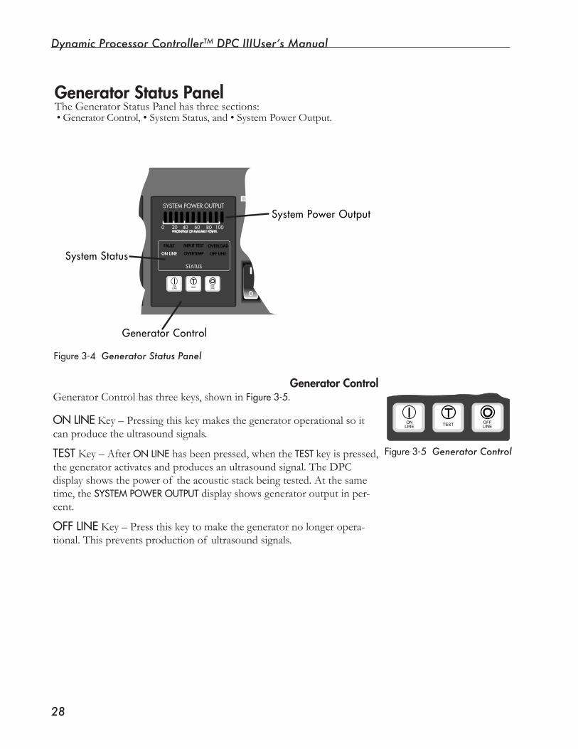
Dynamic Processor ControllerTM DPC IIIUser’s Manual
��
2017
STATUS
FAULT
ON LINE
INPUT TEST
OVERTEMP
OVERLOAD
OFF LINE
ON �LINE TEST OFF �
LINE
0 20 40 60 80 100PERCENTAGEOFAVAILABLEPOWER
SYSTEMPOWEROUTPUT
�Dynamic Process Controller16 Bit Micro �
TM
�
OPERATECANCEL
SETUP
ENTER
DPC III
�
GeneratorControl
SystemStatus
SystemPowerOutput
Generator ControlGenerator Control has three keys, shown in Figure3-5.
ONLINE Key – Pressing this key makes the generator operational so it can produce the ultrasound signals.
TEST Key – After ONLINEhasbeenpressed,whentheTEST key is pressed, the generator activates and produces an ultrasound signal. The DPC displayshowsthepowerof theacousticstackbeingtested.Atthesametime, the SYSTEMPOWEROUTPUTdisplayshowsgeneratoroutputinper-cent.
OFFLINE Key – Press this key to make the generator no longer opera-tional. This prevents production of ultrasound signals.
Generator Status PanelThe GeneratorStatusPanelhasthreesections:• Generator Control, • System Status,and•SystemPowerOutput.
Figure3-4 Generator Status Panel
Figure3-5 Generator Control
ON�LINE TEST OFF�
LINE

Section � Controls
��
OVERTEMP – Thisindicatorlightsif inputoroutputpowermodulesoverheat.Thegeneratorthenautomaticallyshutsdown.Itresetswhenitreaches75°C.
OVERLOAD –Thisindicatorlightswheneitherof thefollowingcondi-tionsoccurs:
•Aninstantaneousoverloadcausedbyamismatchbetweentheultra-sound signal and the vibrational characteristics of the acoustic stack (transducer, booster and horn).
•Excesspowerbeyondthegeneratorpowerratingisbeingdrawnfromthe generator.
The ultrasound signal is shut down when an overload occurs.
The red warning indicator in the SYSTEMPOWEROUTPUT section of the panel lights just prior to an average over-load indication. See Figure3-8.
NOTE
System StatusThe STATUSdisplayshowsthestatusof sixconditions.If acondition’sstatus is “active”, the name of the condition is lighted in the System Status Display.InFigure3-6, ONLINEis active.Theconditionsareexplainedbelow.
ONLINEandOFFLINE – One or the other of these generator con-ditionscanbeactiveatonce.Thecorrespondingwordsshowingtheactive status are lit in the System Status Display.
Figure3-6 System Status Display
STATUS
FAULTON LINE
INPUT TESTOVERTEMP
OVERLOADOFF LINE
INPUTTEST – Thisindicatorflashesduringthepower-uptestsequence.Itwillalsolightif afaultoccursontheinputmodulecircuit.
FAULT – Thisindicatorlightswhenout-of-tolerancevoltagefluctua-tionsoccurthatarerelatedtooneof thefollowing:
• AC line voltage.
•AninternalDCpowersupply(+5VDC;-12VDC;+12VDC;or,+24VDC).
•Thepowerfactorcircuitsand/orthe360VDCbus.
Continued

Dynamic Processor ControllerTM DPC IIIUser’s Manual
�0
�
2017
STATUS
FAULT
ON LINE
INPUT TEST
OVERTEMP
OVERLOAD
OFF LINE
ON�LINE TEST OFF�
LINE
0 20 40 60 80 100PERCENTAGEOFAVAILABLEPOWER
SYSTEMPOWEROUTPUT
�Dynamic Process Controller16 Bit Micro �
TM
�
OPERATECANCEL
SETUP
ENTER
DPC III
ON
OFF
GreenPowerOnLED
ACPowerSwitch
Pushthe"I"endoftheswitchtoturnpoweron.
Pushthe"0"endoftheswitchtoturnpoweroff.
AC PowerTheACpowersectionhas:
• AnON/OFFswitchforACelectricalpower.
• AgreenLEDindicatorthatlightswhenpowerhasbeenswitched“on”.
NOTE
The ON/OFF switch is also a circuit breaker that pro-vides overload protection for the DPC. This switch works together with a similar AC breaker switch on the rear panel.
System Power OutputThe three colorSYSTEMPOWEROUTPUT display indicates the percentage of ultrasonicpowerbeingdrawnbytheload.
• GREEN indicates normal operation. If the rear–panel amplitude con-trolissettolessthan100%,thepowermeterwillreflectthereducedamplitude signal.
Figure3-7showsthegroupof “normal”indicators.
•YELLOWwarnsthatapotentialoverloadconditionexists.
•REDwarnsthatanoverloadconditionexists.
Figure3-8showswhichindicatorswarnof overloadconditions.
Green
Yellow Red
0 20 40 60 80 100
SYSTEM POWER OUTPUT
PERCENTAGE OF AVAILABLE POWER
Figure3-8 Warning Indicators
Figure3-7 Normal Operation Indicators
60 80 100
WER OUTPUT
ABLE POWER60 80 100
WER OUTPUT
ABLE POWER
Figure3-9 AC Power Switch
Makesureelec-tricalpowerisoffbeforeconnect-ingordisconnect-
ingcablestotheDPC.PutboththefrontpanelON/OFFswitchandtherearpanelACbreakerswitchintheOFFposi-tionwhenevercablesareconnectedtoordiscon-nectedfromtheDPC.
CAUTION
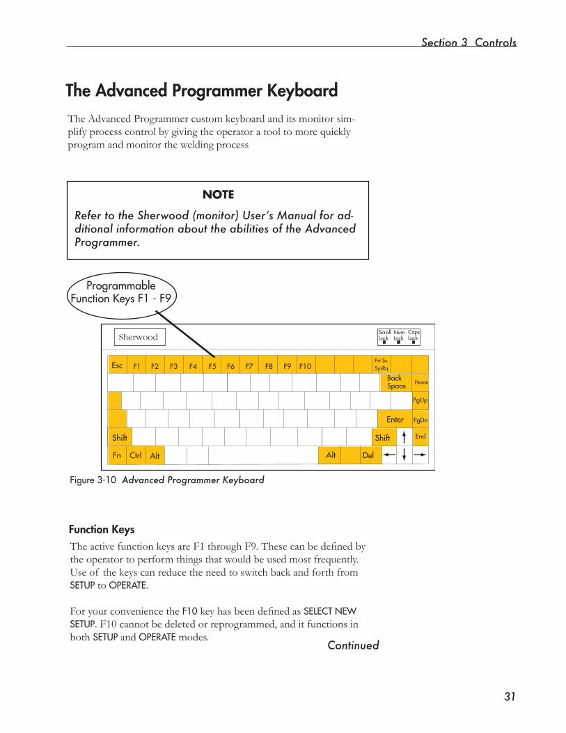
Section � Controls
��
The Advanced Programmer KeyboardThe Advanced Programmer custom keyboard and its monitor sim-plify process control by giving the operator a tool to more quickly programandmonitortheweldingprocess
Figure3-10 Advanced Programmer Keyboard
Function KeysTheactivefunctionkeysareF1throughF9.Thesecanbedefinedbytheoperatortoperformthingsthatwouldbeusedmostfrequently.Useof thekeyscanreducetheneedtoswitchbackandforthfromSETUPto OPERATE.
For your convenience the F10keyhasbeendefinedasSELECTNEWSETUP. F10 cannot be deleted or reprogrammed, and it functions in both SETUPand OPERATEmodes.
Continued
Sherwood
Esc
Enter
Shift Shift
Ctrl AltAltFn
BackSpace
PgUp
PgDn
End
Home
Del
ScrollLock
NumLock
CapsLock
F1 F2 F3 F4 F5 F6 F7 F8 F9 F10Prt ScSysRq
ProgrammableFunctionKeysF1-F9
NOTE
Refer to the Sherwood (monitor) User’s Manual for ad-ditional information about the abilities of the Advanced Programmer.
Dynamic Processor ControllerTM DPC IIIUser’s Manual
��
Function Keys, continued
Programming a Function Key
NOTEProgramming the function keys can only be done in SETUP mode.
Toprogramafunctionkey:
1. Highlightthenumber,list,ortextentryfieldyouwanttoprogram.
2. Press and hold the SHIFTkey.
3. Press the function key (F1 through F9) to be programmed .
4. Oneof twomessageswillbedisplayed: KEYPROGRAMMED, or
KEYDEFINED-OKTOOVERWRITE?
5. If thekeyisalreadydefined,youcaneither: • Abort the programming process by selecting NO, or •OverwritethepreviousprogrammingbyselectingYES.
Removing a Function Key’s Program
To remove the programming from a function key, the Advanced Pro-grammer display must be in the OPERATEmode. The procedure is similar toprogrammingafunctionkey:
1. Press and hold the SHIFT key.
2. Press the function key to be changed.
3. Amessageappearsaskingtheoperatortoconfirmwhetherthefunc-tion key’s program is to be deleted.
4. Theoperatorcaneither: •AbortthedeleteprocedurebyansweringNO, or •Deletethefunctionkey’sprogrambyansweringYES.
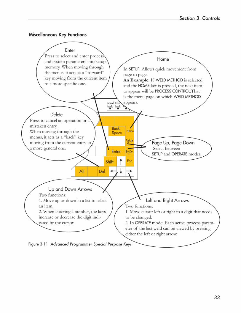
Section � Controls
��
Enter
Shift
Alt
BackSpace
PgUp
PgDn
End
Home
Del
ScrollLock
NumLock
CapsLock
Miscellaneous Key Functions
In SETUP:Allowsquickmovementfrompage to page.An Example: If WELDMETHOD is selected and the HOME key is pressed, the next item toappearwillbePROCESSCONTROL.That isthemenupageonwhichWELDMETHOD appears.
UpandDownArrowsTwofunctions:1.Moveupordowninalisttoselectan item.2. When entering a number, the keys increase or decrease the digit indi-cated by the cursor.
PageUp,PageDownSelectbetweenSETUP and OPERATE modes.
LeftandRightArrowsTwofunctions:1. Move cursor left or right to a digit that needs to be changed.2. In OPERATEmode:Eachactiveprocessparam-eterof thelastweldcanbeviewedbypressingeithertheleftorrightarrow.
Home
DeletePress to cancel an operation or a mistaken entry.When moving through the menus, it acts as a “back” key moving from the current entry to a more general one.
Figure3-11 Advanced Programmer Special Purpose Keys
EnterPress to select and enter process and system parameters into setup memory. When moving through themenus,itactsasa“forward”key moving from the current item toamorespecificone.

Dynamic Processor ControllerTM DPC IIIUser’s Manual
��
Blocking Access to SETUP Mode
Access to the SETUPmodefunctionsisblockedwhentheFrontPanelkeyisremovedfromthekeyswitchwhiletheunitisinOPERATEmode. (See Page27.)
If theunithastheAdvancedProgrammerhowever,thekeyboardPgUp and PgDnkeyscanbeusedtoswitchbetweenmodeseventhoughthefrontpanelkeyswitchislockedintheOPERATEposition. To block access to the SETUPmode in this case, disconnect the keyboard from the moni-tor, and store the keyboard securely.

SECTION 4
Start-up• Start-up sequences are explained.
Dukane Corporation

Dynamic Processor ControllerTM DPC IIIUser’s Manual
��
This page intentionally left blank
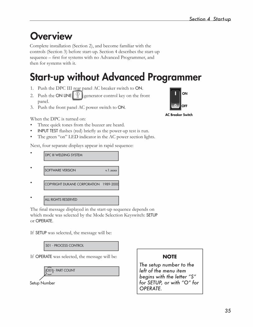
Section 4 Start-up
��
Start-up without Advanced Programmer1. PushtheDPCIIIrearpanelACbreakerswitchtoON. 2. Push the ONLINE generator control key on the front
panel. 3. PushthefrontpanelACpowerswitchtoON.
WhentheDPCisturnedon:• Three quick tones from the buzzer are heard.• INPUTTESTflashes(red)brieflyasthepower-uptestisrun.• Thegreen“on”LEDindicatorintheACpowersectionlights.
Next,fourseparatedisplaysappearinrapidsequence:
•
•
•
•
Thefinalmessagedisplayedinthestart-upsequencedependsonwhichmodewasselectedbytheModeSelectionKeyswitch:SETUP or OPERATE.
If SETUPwasselected,themessagewillbe:
If OPERATEwasselected,themessagewillbe:
Overview
DPCIIIWELDINGSYSTEM
SOFTWAREVERSIONv.1.xxxx
S01-PROCESSCONTROL
ON�LINE
AC Breaker Switch
OFF
ON
O01-PARTCOUNT
SetupNumber
Completeinstallation(Section2),andbecomefamiliarwiththecontrols (Section 3) before start-up. Section 4 describes the start-up sequence–firstforsystemswithnoAdvancedProgrammer,andthenforsystemswithit.
NOTEThe setup number to the left of the menu item begins with the letter “S” for SETUP, or with “O” for OPERATE.
COPYRIGHTDUKANECORPORATION1989-2000
ALLRIGHTSRESERVED
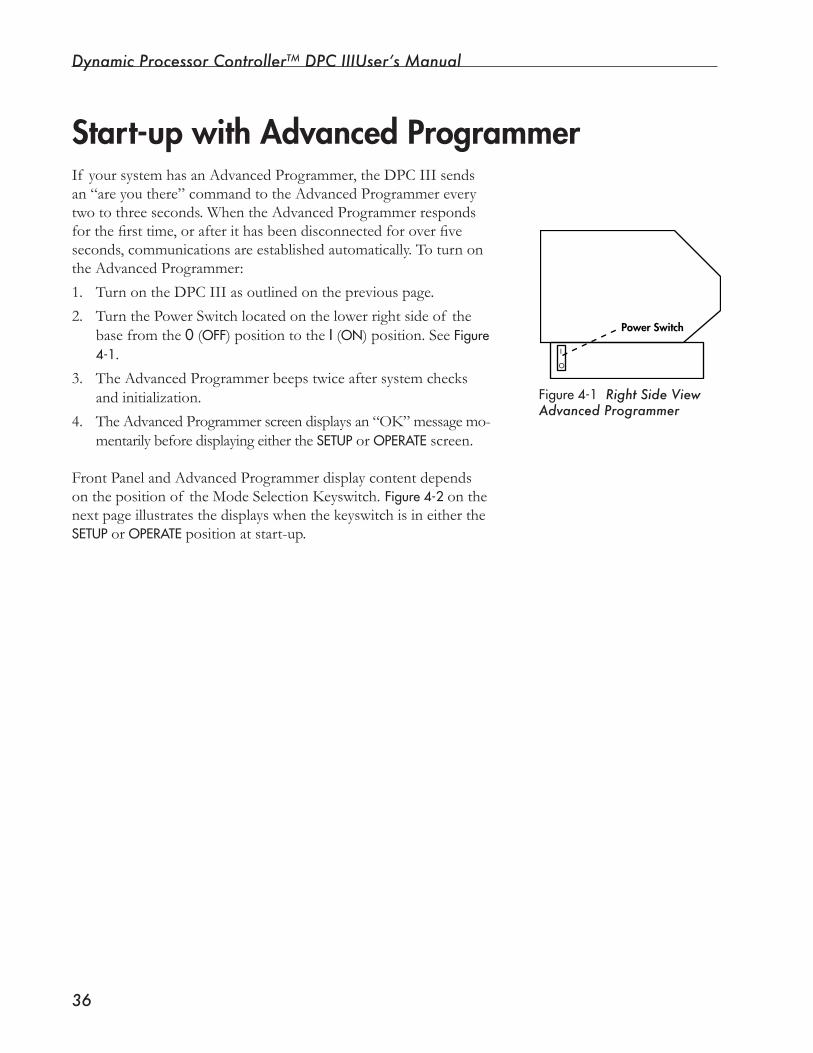
Dynamic Processor ControllerTM DPC IIIUser’s Manual
��
Start-up with Advanced Programmer
I
O
Power Switch
Figure4-1 Right Side ViewAdvanced Programmer
If your system has an Advanced Programmer, the DPC III sends an “are you there” command to the Advanced Programmer every twotothreeseconds.WhentheAdvancedProgrammerrespondsforthefirsttime,orafterithasbeendisconnectedforoverfiveseconds, communications are established automatically. To turn on theAdvancedProgrammer:
1. Turn on the DPC III as outlined on the previous page.
2. TurnthePowerSwitchlocatedonthelowerrightsideof thebase from the 0 (OFF) position to the I (ON) position. See Figure4-1.
3. TheAdvancedProgrammerbeepstwiceaftersystemchecksand initialization.
4. The Advanced Programmer screen displays an “OK” message mo-mentarily before displaying either the SETUPor OPERATEscreen.
Front Panel and Advanced Programmer display content depends onthepositionof theModeSelectionKeyswitch.Figure4-2on the nextpageillustratesthedisplayswhenthekeyswitchisineithertheSETUPor OPERATEposition at start-up.
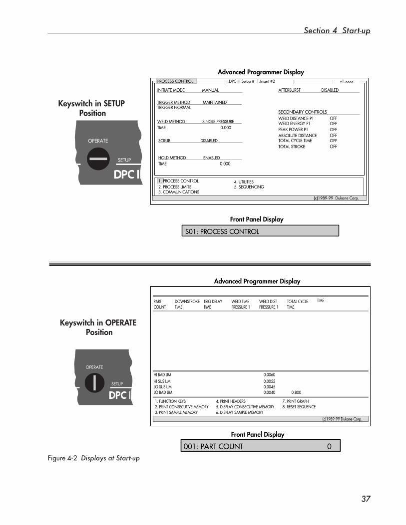
Section 4 Start-up
��
Figure4-2Displays at Start-up
Keyswitch in OPERATE Position
Keyswitch in SETUP Position
OPERATE
SETUP
DPC III
PROCESSCONTROL
INITIATEMODEMANUAL
TRIGGERMETHODMAINTAINEDTRIGGERNORMAL
AFTERBURSTDISABLED
OFF
OFFOFFOFF
OFFOFF
WELDDISTANCEP1WELDENERGYP1PEAKPOWERP1ABSOLUTEDISTANCETOTALCYCLETIMETOTALSTROKE
DPCIIISetup#1:Insert#2 v1.xxxx
1.PROCESSCONTROL2.PROCESSLIMITS3.COMMUNICATIONS
4.UTILITIES5.SEQUENCING
(c)1989-99DukaneCorp.
WELDMETHODSINGLEPRESSURE
SCRUBDISABLED
HOLDMETHODENABLEDTIME0.000
TIME0.000
S01:PROCESSCONTROL
Advanced Programmer Display
Front Panel Display
(c)1989-99DukaneCorp.
1.FUNCTIONKEYS2.PRINTCONSECUTIVEMEMORY3.PRINTSAMPLEMEMORY
4.PRINTHEADERS5.DISPLAYCONSECUTIVEMEMORY6.DISPLAYSAMPLEMEMORY
7.PRINTGRAPH8.RESETSEQUENCE
PARTCOUNT
DOWNSTROKETIME
TRIGDELAYTIME
WELDTIMEPRESSURE1
WELDDISTPRESSURE1
TOTALCYCLETIME
TIME
HIBADLIMHISUSLIMLOSUSLIMLOBADLIM
0.00600.00550.00450.0040 0.800
Front Panel Display
Advanced Programmer Display
001:PARTCOUNT0
SECONDARYCONTROLS
�
OPERATE
SETUP
DPC III

Dynamic Processor ControllerTM DPC IIIUser’s Manual
��
Stopping the Weld CycleNormal ConditionsThecyclestopswhentheprogrammedcycleends.
Emergency ConditionsManual SystemPress the red, PUSHFOREMERGENCYOFFswitchonthepressbaseplate.
Automated SystemCustomer-supplied external controls provide the means to stop the cycle for an automated system.An auxiliary cable connects these external controls to the DPC at con-nector J902. See Figure2-4, Page 16.

SECTION 5
Menu Orientation• This section provides orientation to menu organization
and to the basics of navigating through the menus.
Dukane Corporation

Dynamic Processor ControllerTM DPC III Plus User’s Manual
This page intentionally left blank

Section 5 Menu Orientation
��
DPC III Menu Organization
OPERATE
SETUP
• PRINT SAMPLE MEMORY
• UTILITIESSetup UtilitiesTime and Date UtilitiesEncoder UtilitiesReset/Preset Part CountUser ParametersPower Utilities
• PROCESS CONTROLInitiate ModeTrigger MethodWeld MethodScrubHold MethodAfterburstSecondary Controls
• PROCESS LIMITSBad LimitsSuspect Limits
• FUNCTION KEYS
FUNCTIONAL MODES
• PRINT CONSECUTIVE MEMORY
• SEQUENCINGSequencingSequence
• COMMUNICATIONSConfigure Serial PortUser IOAdvanced ProgrammerPart SamplingGraphing
• PRINT HEADERS • DISPLAY CONSECUTIVE MEMORY • DISPLAY SAMPLE MEMORY
• PRINT GRAPH • RESET SEQUENCE
Figure5-1 DPC III Menu Organization
Overview
Both Front Panel and Advanced Programmer control are considered. Figure5-1illustrateshowthemenuisorganizedunderthetwomainfunctional modes, SETUP and OPERATE.
This section of the user’s manual provides orientation to the DPC III menu by providing;• TermstoKnow,and• Instructiononnavigatingthroughthemenu–firstinSETUP
mode and then in OPERATEmode.

Dynamic Processor ControllerTM DPC IIIUser’s Manual
�0
Terms to Know
Menu ItemEachwordorphraseappearingontheFrontPaneldisplayorontheAd-vanced Programmer display is a menu item. The single-line Front Panel displayshowsmenuitemsoneatatime,whilethefull-screenAdvancedProgrammerdisplayshowsmanymenuitemsatonce.
NOTEThese terms apply to the way the DPC III program has been put together. Knowing what these terms mean will help in understanding how to move through the program.
NOTEThe menu item currently selected on the Advanced Pro-grammer display is highlighted in reverse video.
PageA page is a collection of menu items grouped under a main topic. For instance,SETUPmodeisorganizedintothesefivepages: • Process Control • Process Limits • Communications • Utilities, and • Sequencing.
MenuThemenuistheDPC’sinterfacebetweentheoperatorandtheprogramthatactuallycompletestheworktobeaccomplished.Themenuismadeup of all the menu items.
Section 5 Menu Orientation
��
Entry FieldsEntryfieldsaremenuitemsthatallowtheoperatortoinputormodifyparameters.Youwillencounterthreetypes:• Numeric• List, and• Text
Numeric Entry Field
Thistypeof entryfieldrequiresnumericvaluestobeentered.Ex-amplesof numericentryfields:
• ENTERWELDTIME,
• ENTERSAMPLESIZE, and
• ENTERPARTCOUNT.
AdvancedProgrammer - Numbers can be entered using the Ad-vanced Programmer’s keyboard number keys and the decimal point key. This is direct parameter entry.Anotherwayof enteringnumbersiswiththeedit mode. A number can be edited by pressing any non-nu-meric key on the keyboard. The current setting is displayed and can
List Entry Field
FrontPanelDisplay- With the Front Panel, using edit mode is the onlywaytomakenumericentries.
This type of entry requires selecting a parameter from a list of choices. Select by using the Advanced Programmer’s numeric keys or byscrollingthroughthelistusingtheUpandDownArrowkeysof the Front Panel or Advanced Programmer. Examplesof listentryfields:
• SELECTINITIATEMODE–MANUAL/AUTO
• SELECTSCRUB–DISABLE/ENABLE
• SELECTBUZZERSTATUS–ON/OFF
Continued
Terms to Know, continued
Dynamic Processor ControllerTM DPC IIIUser’s Manual
��
Text Entry Field
This type of entry requires entering strings of text. Text entry is done as wasnumericentrywiththeexceptionthatupperandlowercaseletters(AtoZ)andpunctuationmarkscanbeused(aswellasnumbers).Examplesof textentryfields:
• JOBID, and
• BOOSTER(description).
NOTEReview what the keys’ functions are by referring to Section3-Controls.
Terms to Know, continued

Section 5 Menu Orientation
��
SETUP
• UTILITIESSetup UtilitiesTime and Date UtilitiesEncoder UtilitiesReset/Preset Part CountUser ParametersPower Utilities
• PROCESS CONTROLInitiate ModeTrigger MethodWeld MethodScrubHold MethodAfterburstSecondary Controls
• PROCESS LIMITSBad LimitsSuspect Limits
• SEQUENCINGSequencingSequence
• COMMUNICATIONSConfigure Serial PortUser IOAdvanced ProgrammerPart SamplingGraphing
Figure5-2 Navigating in SETUP Mode
Navigating in SETUP Mode
Figure5-2illustratesatypical“flow”whennavigatingthroughtheSETUPportionof themenu.StartingwiththePROCESSCONTROL page and end-ingwiththeSEQUENCINGpage, the gray line indicates that each menu itemislinkedtotheonethatfollows(orprecedes)it.
Continued
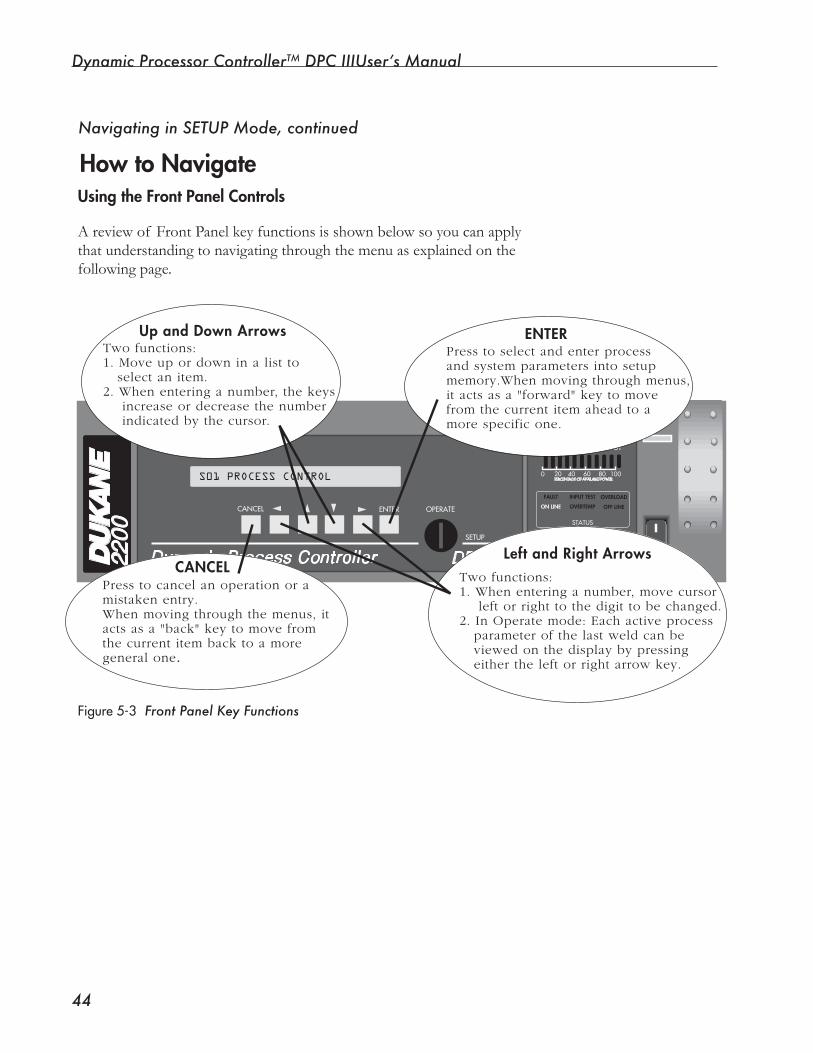
Dynamic Processor ControllerTM DPC IIIUser’s Manual
��
How to NavigateUsing the Front Panel Controls
Navigating in SETUP Mode, continued
Figure5-3 Front Panel Key Functions
Areviewof FrontPanelkeyfunctionsisshownbelowsoyoucanapplythat understanding to navigating through the menu as explained on the followingpage.
2200
STATUS
FAULT
ON LINE
INPUT TEST
OVERTEMP
OVERLOAD
OFF LINE
ONLINE TEST OFF
LINE
0 20 40 60 80 100PERCENTAGE OF AVAILABLE POWER
SYSTEM POWER OUTPUT
Dynamic Process Controller
OPERATECANCEL
SETUP
ENTER
S01 PROCESS CONTROL
DPC™ III
Press to cancel an operation or amistaken entry.When moving through the menus, itacts as a "back" key to move fromthe current item back to a more general one.
Press to select and enter process and system parameters into setupmemory.When moving through menus,it acts as a "forward" key to move from the current item ahead to amore specific one.
ENTER
CANCELLeft and Right Arrows
Two functions:1. When entering a number, move cursor left or right to the digit to be changed.2. In Operate mode: Each active process parameter of the last weld can be viewed on the display by pressing either the left or right arrow key.
Up and Down ArrowsTwo functions:1. Move up or down in a list to select an item.2. When entering a number, the keys increase or decrease the number indicated by the cursor.
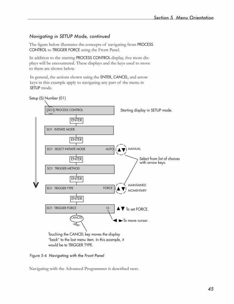
Section 5 Menu Orientation
��
Selectfromlistofchoiceswitharrowkeys.
TosetFORCE.
Tomovecursor.
TouchingtheCANCELkeymovesthedisplay“back”tothelastmenuitem.Inthisexample,itwouldbetoTRIGGERTYPE.
Navigating in SETUP Mode, continued
SO1SELECTINITIATEMODEAUTO
SO1TRIGGERMETHOD
SO1TRIGGERTYPE
SO1TRIGGERFORCE
ENTER
SO1PROCESSCONTROL
SO1INITIATEMODE
ENTER
MANUAL
ENTER
FORCEMAINTAINED
MOMENTARY
ENTER
ENTER
10
CANCEL
Ingeneral,theactionsshownusingtheENTER, CANCEL,andarrowkeys in this example apply to navigating any part of the menu in SETUP mode.
StartingdisplayinSETUPmode.
Figure5-4 Navigating with the Front Panel
Thefigurebelowillustratestheconceptsof navigatingfromPROCESSCONTROL to TRIGGERFORCE using the Front Panel.
In addition to the starting PROCESSCONTROLdisplay,fivemoredis-playswillbeencountered.Thesedisplaysandthekeysusedtomovetothemareshownbelow.
NavigatingwiththeAdvancedProgrammerisdescribednext.
Setup(S)Number(01)
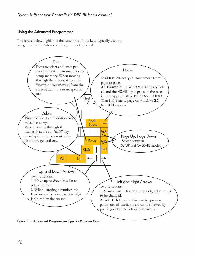
Dynamic Processor ControllerTM DPC IIIUser’s Manual
��
Using the Advanced Programmer
Figure5-5 Advanced Programmer Special Purpose Keys
Thefigurebelowhighlightsthefunctionsof thekeystypicallyusedtonavigatewiththeAdvancedProgrammerkeyboard.
Enter
Shift
Alt
BackSpace
PgUp
PgDn
End
Home
Del
ScrollLock
NumLock
CapsLock
In SETUP:Allowsquickmovementfrompage to page.An Example: If WELDMETHOD is select-ed and the HOME key is pressed, the next itemtoappearwillbePROCESSCONTROL. ThatisthemenupageonwhichWELDMETHOD appears.
UpandDownArrowsTwofunctions:1.Moveupordowninalisttoselect an item.2. When entering a number, the keys increase or decrease the digit indicated by the cursor.
PageUp,PageDownSelectbetweenSETUP and OPERATE modes.
LeftandRightArrowsTwofunctions:1. Move cursor left or right to a digit that needs to be changed.2. In OPERATEmode:Eachactiveprocessparameterof thelastweldcanbeviewedbypressingeithertheleftorrightarrow.
DeletePress to cancel an operation or a mistaken entry.When moving through the menus, it acts as a “back” key moving from the current entry to a more general one.
EnterPress to select and enter pro-cess and system parameters into setup memory. When moving through the menus, it acts as a “forward”keymovingfromthecurrentitemtoamorespecificone.
Home
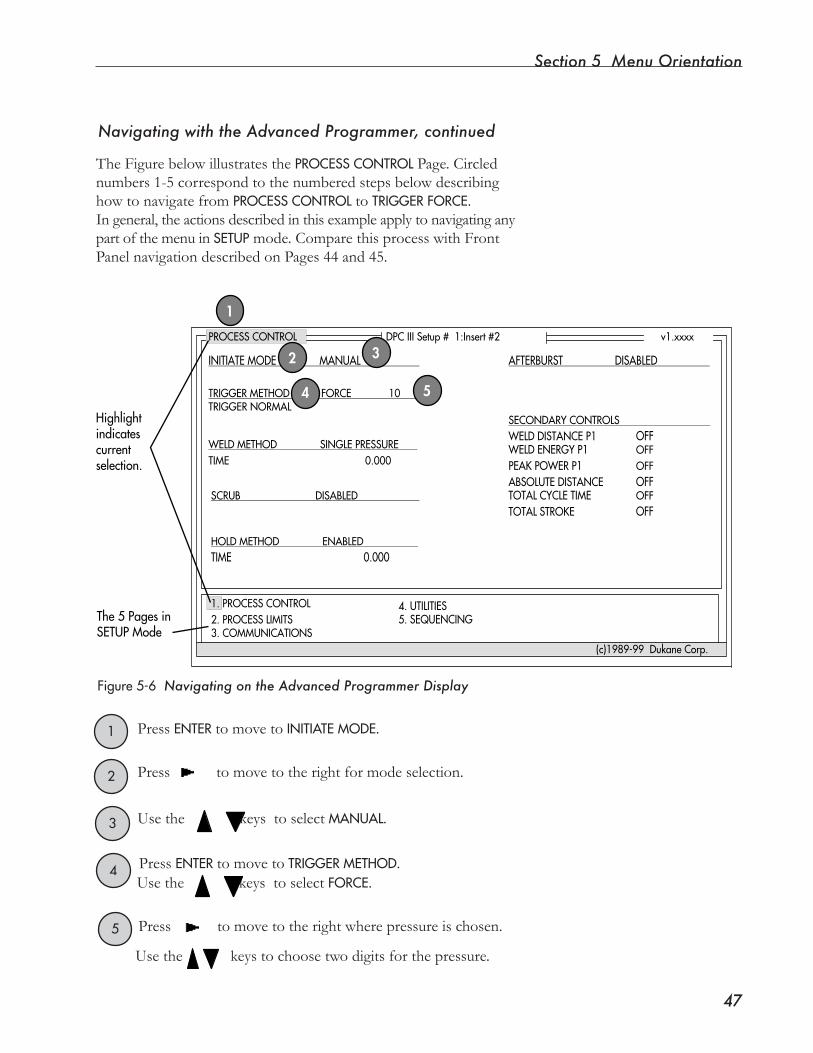
Section 5 Menu Orientation
��
TheFigurebelowillustratesthePROCESSCONTROL Page. Circled numbers1-5correspondtothenumberedstepsbelowdescribinghowtonavigatefromPROCESSCONTROL to TRIGGERFORCE.In general, the actions described in this example apply to navigating any part of the menu in SETUPmode.ComparethisprocesswithFrontPanel navigation described on Pages 44 and 45.
PROCESSCONTROL
INITIATEMODEMANUAL
TRIGGERMETHODFORCE10TRIGGERNORMAL
AFTERBURSTDISABLED
SECONDARYCONTROLS
OFF
OFFOFFOFF
OFFOFF
WELDDISTANCEP1WELDENERGYP1PEAKPOWERP1ABSOLUTEDISTANCETOTALCYCLETIMETOTALSTROKE
DPCIIISetup#1:Insert#2 v1.xxxx
1.PROCESSCONTROL2.PROCESSLIMITS3.COMMUNICATIONS
4.UTILITIES5.SEQUENCING
(c)1989-99DukaneCorp.
WELDMETHODSINGLEPRESSURE
SCRUBDISABLED
HOLDMETHODENABLEDTIME0.000
TIME0.000
Highlightindicatescurrentselection.
The5PagesinSETUPMode
1
3
4 5
2
1 Press ENTERto move toINITIATEMODE.
2 Press to move to the right for mode selection.
3
Figure5-6 Navigating on the Advanced Programmer Display
Use the keys to select MANUAL.
4 Press ENTERto move toTRIGGERMETHOD.
5
Use the keys to select FORCE.
Press tomovetotherightwherepressureischosen.
Usethekeystochoosetwodigitsforthepressure.
Navigating with the Advanced Programmer, continued
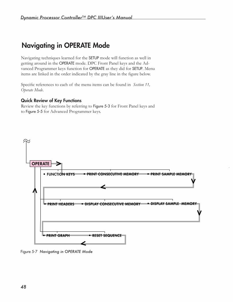
Dynamic Processor ControllerTM DPC IIIUser’s Manual
��
Navigating in OPERATE Mode
Navigating techniques learned for the SETUPmodewillfunctionaswellingetting around in the OPERATEmode. DPC Front Panel keys and the Ad-vanced Programmer keys function for OPERATE as they did for SETUP. Menu itemsarelinkedintheorderindicatedbythegraylineinthefigurebelow.
Specificreferencestoeachof themenuitemscanbefoundinSection 11, Operate Mode.
Quick Review of Key FunctionsReviewthekeyfunctionsbyreferringtoFigure5-3 for Front Panel keys and toFigure5-5 for Advanced Programmer keys.
Figure5-7 Navigating in OPERATE Mode
OPERATE
•PRINT SAMPLE MEMORy•FUNCTION KEyS •PRINT CONSECUTIVE MEMORy
•PRINT GRAPH •RESET SEQUENCE
•PRINT HEADERS •DISPLAy CONSECUTIVE MEMORy •DISPLAy SAMPLE MEMORy
SECTION 6
Setup Mode, Process Control Page• This section outlines the settings that have to be consideredandmadebeforeultrasonicweldingcan begin.
Dukane Corporation

Dynamic Processor ControllerTM DPC III Plus User’s Manual
This page intentionally left blank

Section 6 Setup Mode, Process Control Page
��
SETUP
• UTILITIESSetup UtilitiesTime and Date UtilitiesEncoder UtilitiesReset/Preset Part CountUser ParametersPower Utilities
• PROCESS CONTROLInitiate ModeTrigger MethodWeld MethodScrubHold MethodAfterburstSecondary Controls
• PROCESS LIMITSBad LimitsSuspect Limits
• SEQUENCINGSequencingSequence
• COMMUNICATIONSConfigure Serial PortUser IOAdvanced ProgrammerPart SamplingGraphing
Figure6-1 SETUP Mode Pages
OverviewThefigurebelowillustratestheSETUPmodemenuanditsfivepages:Process Control; Process Limits; Communications; Utilities; and, Sequencing.Section 6 provides basic information about using the Process Con-trolPage.Sections7-10dealwitheachof thefourotherpages:Pro-cess Limits, Communications, Utilities, and Sequencing respectively.
Continued
NOTEReview how to select SETUP mode by referring to Pages 27 and 33.
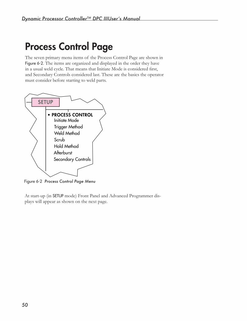
Dynamic Processor ControllerTM DPC IIIUser’s Manual
�0
Process Control PageThesevenprimarymenuitemsof theProcessControlPageareshowninFigure6-2. The items are organized and displayed in the order they have inausualweldcycle.ThatmeansthatInitiateModeisconsideredfirst,and Secondary Controls considered last. These are the basics the operator mustconsiderbeforestartingtoweldparts.
SETUP
•PROCESS CONTROLInitiateModeTriggerMethodWeldMethodScrubHoldMethodAfterburstSecondaryControls
Figure6-2 Process Control Page Menu
At start-up (in SETUPmode) Front Panel and Advanced Programmer dis-playswillappearasshownonthenextpage.
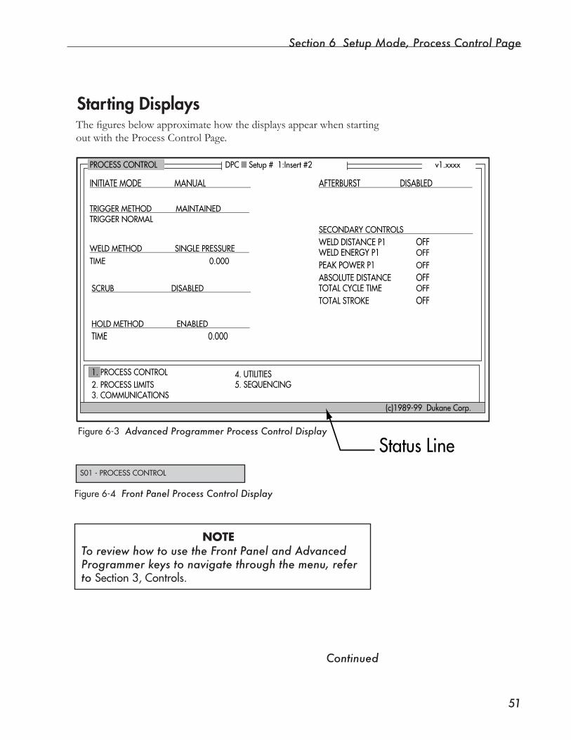
Section 6 Setup Mode, Process Control Page
��
PROCESSCONTROL
INITIATEMODEMANUAL
TRIGGERMETHODMAINTAINEDTRIGGERNORMAL
AFTERBURSTDISABLED
SECONDARYCONTROLS
OFF
OFFOFFOFF
OFFOFF
WELDDISTANCEP1WELDENERGYP1PEAKPOWERP1ABSOLUTEDISTANCETOTALCYCLETIMETOTALSTROKE
DPCIIISetup#1:Insert#2 v1.xxxx
1.PROCESSCONTROL2.PROCESSLIMITS3.COMMUNICATIONS
4.UTILITIES5.SEQUENCING
(c)1989-99DukaneCorp.
WELDMETHODSINGLEPRESSURE
SCRUBDISABLED
HOLDMETHODENABLEDTIME0.000
TIME0.000
StatusLineS01-PROCESSCONTROL
Figure6-3 Advanced Programmer Process Control Display
Figure6-4 Front Panel Process Control Display
ThefiguresbelowapproximatehowthedisplaysappearwhenstartingoutwiththeProcessControlPage.
Starting Displays
Continued
NOTETo review how to use the Front Panel and Advanced Programmer keys to navigate through the menu, refer to Section3,Controls.
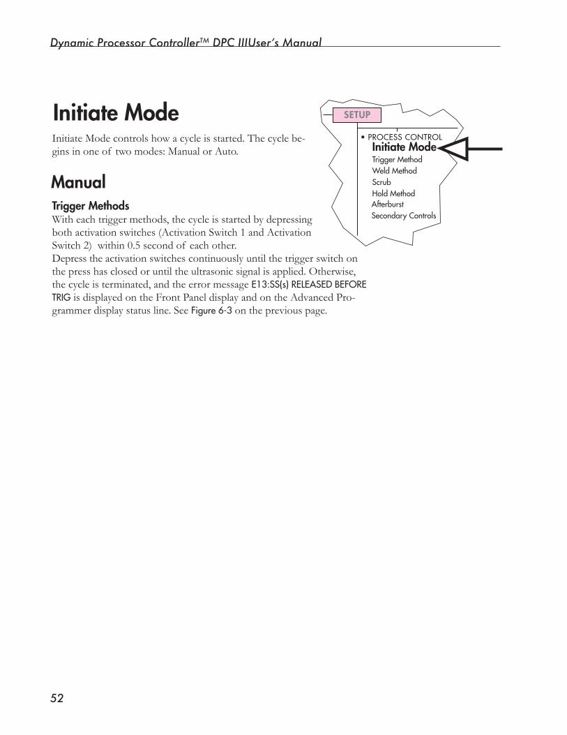
Dynamic Processor ControllerTM DPC IIIUser’s Manual
��
Initiate ModeInitiateModecontrolshowacycleisstarted.Thecyclebe-ginsinoneof twomodes:ManualorAuto.
ManualTrigger MethodsWith each trigger methods, the cycle is started by depressing bothactivationswitches(ActivationSwitch1andActivationSwitch2)within0.5secondof eachother.Depresstheactivationswitchescontinuouslyuntilthetriggerswitchonthepresshasclosedoruntiltheultrasonicsignalisapplied.Otherwise,the cycle is terminated, and the error message E13:SS(s)RELEASEDBEFORETRIG is displayed on the Front Panel display and on the Advanced Pro-grammer display status line. See Figure6-3on the previous page.
SETUP
•PROCESSCONTROLInitiate ModeTriggerMethodWeldMethodScrubHoldMethodAfterburstSecondaryControls
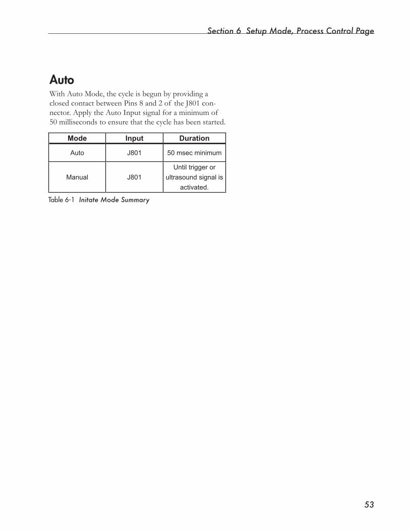
Section 6 Setup Mode, Process Control Page
��
Table6-1 Initate Mode Summary
AutoWith Auto Mode, the cycle is begun by providing a closedcontactbetweenPins8and2of theJ801con-nector. Apply the Auto Input signal for a minimum of 50 milliseconds to ensure that the cycle has been started.
Mode Input Duration
Auto J801 50 msec minimum
Manual J801
Until trigger or
ultrasound signal is
activated.
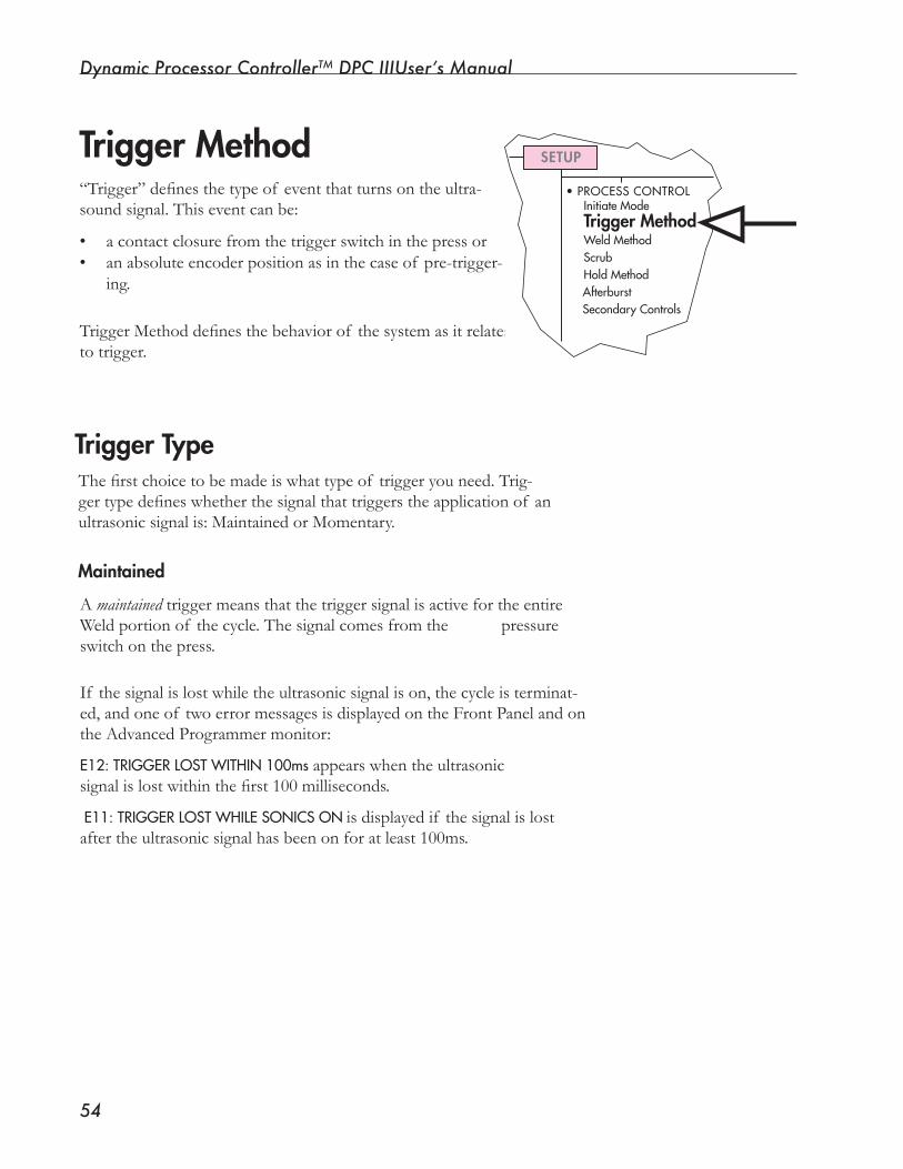
Dynamic Processor ControllerTM DPC IIIUser’s Manual
��
Thefirstchoicetobemadeiswhattypeof triggeryouneed.Trig-gertypedefineswhetherthesignalthattriggerstheapplicationof anultrasonicsignalis:MaintainedorMomentary.
Trigger Type
Trigger Method “Trigger”definesthetypeof eventthatturnsontheultra-soundsignal.Thiseventcanbe:
• acontactclosurefromthetriggerswitchinthepressor• an absolute encoder position as in the case of pre-trigger-
ing.
TriggerMethoddefinesthebehaviorof thesystemasitrelatesto trigger.
SETUP
• PROCESS CONTROLInitiate ModeTrigger MethodWeld MethodScrubHold MethodAfterburstSecondary Controls
Maintained
A maintained trigger means that the trigger signal is active for the entire Weld portion of the cycle. The signal comes from the pressure switchonthepress. If thesignalislostwhiletheultrasonicsignalison,thecycleisterminat-ed,andoneof twoerrormessagesisdisplayedontheFrontPanelandontheAdvancedProgrammermonitor:
E12:TRIGGERLOSTWITHIN100msappearswhentheultrasonicsignalislostwithinthefirst100milliseconds.
E11:TRIGGERLOSTWHILESONICSON is displayed if the signal is lost after the ultrasonic signal has been on for at least 100ms.
Section 6 Setup Mode, Process Control Page
��
TIPHere are some reasons the triggerswitchmaybelost:The application may need a light trigger setting and lowpressurecausingthepress inertia at the start of thedownstroketoclosethetriggerswitch.Anotherreason:Involvesuse of Kinechek (hydraulic speed control). If the mate-rial melts at a rate faster than the horn descends, pressure is lost at the face of the horn, and the trig-gerswitchcanopen.
Momentary
With a momentarytrigger,thetriggerswitchisignoredafteritclosesonce.If thetriggerswitchopensduringtheweldportionof thecycle,theweldcontinuesnormally.Noerrormessageisgenerated.
Be certain that the application of the ultrasonic signal is due to contact with the part, and not due to anything else. This can be determined by setting
downstroke limits for distance and time.
Use extreme caution when using the Momentary trigger type. Open-ing the trigger switch will NOT ter-
minate the weld cycle. Guard the horn/fixture “pinch point” to prevent hands, or fingers from being crushed by the vibrating horn.
Continued
CAUTION
CAUTION
Once a trigger type has been selected, a trigger method can be chosen fromthisgroupof sixmethods:
• Normal Trigger • Delay Trigger by Time • Delay Trigger by Distance • Delay Trigger till Auto-In, • Pre-trigger by Distance, and • Probe Mode.
Dynamic Processor ControllerTM DPC IIIUser’s Manual
��
Trigger Method, continued
Trigger Method 1: Normal Trigger
Theultrasoundsignalisappliedwhenthetriggerswitchinthepresscloses or the force read from the force transducer reaches its preset limit (the force built up after the horn contacts the part).
Trigger Method 2: Delay by Time
Thismethoddelaysthestartoftheultrasoundsignalbyaspecifiedtime.Otherwise,thismethodisthesameas“NormalTrigger”.
Entering Trigger Delay by Time
Enter trigger delay time in seconds from 0 to 99.999 in increments of 1 millisecond.
NOTEThe force needed to close the trigger switch can be adjust-ed by rotating the trigger adjustment knob on the thruster. In systems equipped with a force transducer, adjust the force by increasing or decreasing the force level with the Front Panel or with the Advanced Programmer when FORCE is the trigger type.
TIPDelaying the trigger causes the ultrasonic signal to bedelayeduntilaspecificevent occurs. The delay allowsadditionalpressurebuild up on the part. In this wayresilientcompoundssuch as O-rings, and gaskets canbecollapsed.Likewise,warpedpartscanbeflat-tened before the ultrasonic signal is turned on.
Section 6 Setup Mode, Process Control Page
��
Trigger Method 3: Delay by Distance (Systems with Distance Encoder Only)
Thismethoddelaysthestartoftheultrasoundsignalbyaspecifieddis-tancebeyondthenormaltriggerpoint.Otherwise,thismethodisthesame as “Normal Trigger”.
Tocontinuetheweldcycleevenif thedelaydistanceisnotmet,aMAXIMUMDELAYTIME value must also be entered.
EnteringTriggerDelaybyDistanceandMaxTime
Enter trigger delay distance in inches from 0 to 9.9999 in increments of 0.0001 inch. (Distance can also be entered in millimeters from 0 to 99.999 mm in increments of 0.001 mm.)
Next, enter MAXTIME in seconds from 0 to 99.999 in increments of 1 millisecond.
Trigger Method 4: Delay till Auto-In
This method delays the start of the ultrasound signal until an Auto-In input (an external signal from customer equipment) is received. Delay till Auto-In can be
used to synchronize the application of ultrasound in a multi-headed applica-tion. During this delay the INDWELL signal on Pin 5 of the J801 connector is asserted(if InDwellhasbeen enabled).
TIP
Delay till Auto-In is in addition to the auto-initiate signal that may have been used.
NOTE
NOTE
Although a press pre-trigger flag could be used, the pur-pose of the Delay till Auto-In feature would be defeated.
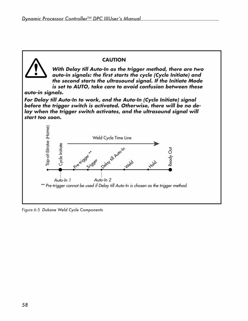
Dynamic Processor ControllerTM DPC IIIUser’s Manual
��
With Delay till Auto-In as the trigger method, there are two auto-in signals: the first starts the cycle (Cycle Initiate) and the second starts the ultrasound signal. If the Initiate Mode is set to AUTO, take care to avoid confusion between these
auto-in signals. For Delay till Auto-In to work, end the Auto-In (Cycle Initiate) signal before the trigger switch is activated. Otherwise, there will be no de-lay when the trigger switch activates, and the ultrasound signal will start too soon.
CAUTION
WeldCycleTimeLine
Cyc
leIn
itiat
e
Read
yO
utPre
-trigg
er**
Hold
WeldDelayt
illAuto
-In
Trigg
er
** Pre-trigger cannot be used if Delay till Auto-In is chosen as the trigger method.Auto-In 1 Auto-In 2
Top
-of-S
troke
(Hom
e)
�
Figure6-5 Dukane Weld Cycle Components
Section 6 Setup Mode, Process Control Page
��
Trigger Method 5: Pre-trigger by Distance (Systems with Distance Encoder Only)
Pre-triggeringisdefinedasturningontheultrasoundsignalbeforethehorncontactsthepart.Inthiswaythehornreachesfullampli-tude before part contact is made.Theultrasoundsignalisturnedonatauser-defineddistance.Thisis measured from the reference mark (zero) of the distance encoder mounted on the press.
NOTE
The maximum travel of the press from the pre-trigger point (without closing the trigger switch or reaching the specified force level) is 0.75 inch (19.05 mm). Exceed-ing this distance results in an E10:PRETRIGGER>0.75inABOVEPART error message, and the cycle terminates.
Insertion,swaging,andstaking can make good use of the Pre-trigger by Dis-tancemethodbyallowingplastic to melt immediately upon horn contact.Pre-triggering can also help to run large, complex horns if overload conditions occur on start-up (if no mechani-cal/electrical faults are foundwithinthesystem). Presslimitswitchescanbe used to pre-trigger the ultrasound signal above the part.
Start Weld At
Whenpre-triggeringbydistance,thehorncontactsthepartwiththeultrasound signal turned on. From the time the horn contacts the parttoclosureof thetriggerswitch,weldingistakingplace.Thismayresultininconsistentweldtimesandwelddistances.
Inothercases,suchaswhenworkingwithsmallparts,insufficientpressuremaykeepthetriggerswitchfromclosingorpreventtheforce transducer from reaching its programmed force level.
Toavoidthesesituationswhenpre-triggering,theusermaychoosetostarttheweldatthepre-triggerpointoratthetriggerpoint.
If thestartof weldisatthepre-triggerpoint,thenallweldparame-terswillbereferencedfromthatpoint.If thestartof weldisdefinedasthetriggerpoint,thenallweldparametersrelatetothepointatwhichthetriggerisclosed.
TIP
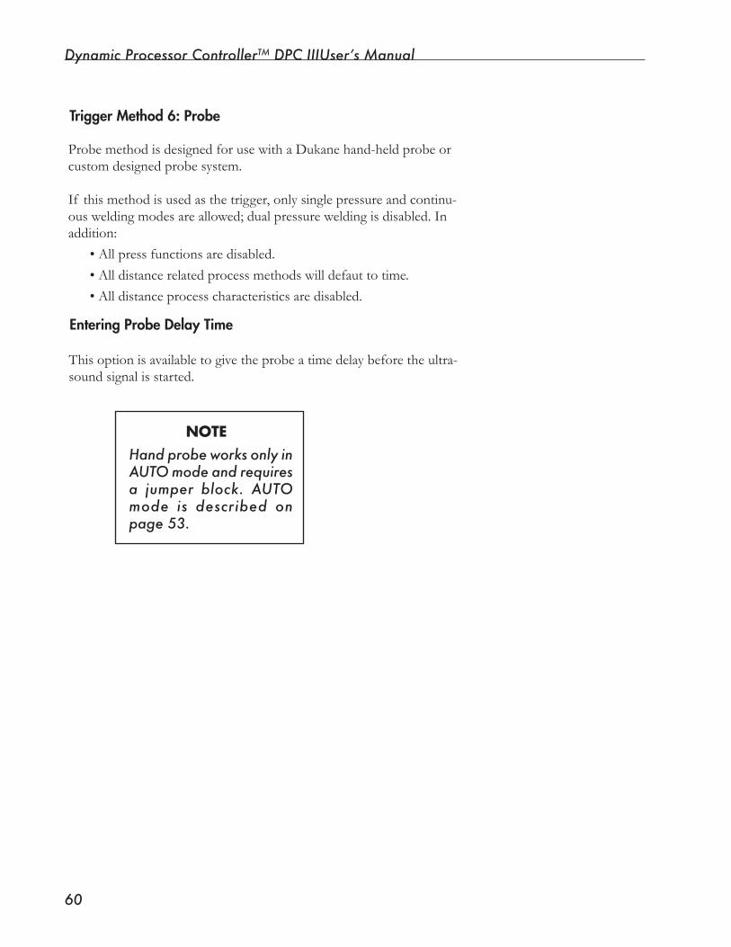
Dynamic Processor ControllerTM DPC IIIUser’s Manual
�0
Trigger Method 6: Probe
ProbemethodisdesignedforusewithaDukanehand-heldprobeorcustom designed probe system.
If this method is used as the trigger, only single pressure and continu-ousweldingmodesareallowed;dualpressureweldingisdisabled.Inaddition:
• All press functions are disabled.•Alldistancerelatedprocessmethodswilldefauttotime.• All distance process characteristics are disabled.
Entering Probe Delay Time
This option is available to give the probe a time delay before the ultra-sound signal is started.
Hand probe works only in AUTO mode and requires a jumper block. AUTO mode is described on page 53.
NOTE
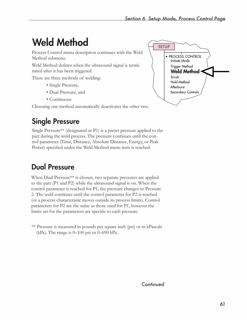
Section 6 Setup Mode, Process Control Page
��
Weld Method
Continued
ProcessControlmenudescriptioncontinueswiththeWeldMethod submenu.WeldMethoddefineswhentheultrasoundsignalistermi-nated after it has been triggered.Therearethreemethodsof welding: • Single Pressure, • Dual Pressure, and • ContinuousChoosingonemethodautomaticallydeactivatestheothertwo.
Single PressureSingle Pressure** (designated as P1) is a preset pressure applied to the partduringtheweldprocess.Thepressurecontinuesuntilthecon-trol parameter (Time, Distance, Absolute Distance, Energy, or Peak Power)specifiedundertheWeldMethodmenuitemisreached.
SETUP
•PROCESSCONTROLInitiateMode
TriggerMethod
Weld MethodScrubHoldMethodAfterburstSecondaryControls
Dual PressureWhenDualPressure**ischosen,twoseparatepressuresareappliedtothepart(P1andP2)whiletheultrasoundsignalison.Whenthecontrol parameter is reached for P1, the pressure changes to Pressure 2.TheweldcontinuesuntilthecontrolparameterforP2isreached(or a process characteristic moves outside its process limits). Control parametersforP2arethesameasthoseusedforP1,howeverthelimitssetfortheparametersarespecifictoeachpressure.
** Pressure is measured in pounds per square inch (psi) or in kPascals (kPa). The range is 0–100 psi or 0–690 kPa.
Dynamic Processor ControllerTM DPC IIIUser’s Manual
��
ContinuousContinuousweldingisusedwhentheparttobeweldedmovescontinu-ously under the horn. Films and fabrics are examples of product types thatrequirecontinuouswelding.
Unlikesingleordualpressurewelding,thismethodhasnocontrolparametertoendthecycle.Withcontinuouswelding,thecycleisendedwhentheinitiatingsignalisremoved.Theamountof materialtobepro-cessed determines cycle length.
Graphing functions are not available in Continuous mode.
Thereportintervalisauser-definedperiodoftimethattellstheDPCwhento output process data (to the output device, or to the Advanced Program-mer).Thisallowsarecordoftheprocesstobeproducedthatcanbeusedas process documentation or input to an SPC (statistical process control) softwarepackageforanalysis.Theminimumintervalisonesecond.
With the exception of TOTALCYCLETIME, all process param-eters are reset after each report interval.
Entering Report Interval
NOTEThe Report Interval usually will not correspond to actual weld time. In fact, the Report Interval time should always be less than actual weld time to produce valid interval data.
NOTE
NOTE
TIPProcess limits are also reported and analyzed from the beginning of each interval.
Section 6 Setup Mode, Process Control Page
��
Control Parameters – Single and Dual Pressure WeldingTime
Welding by time means that the DPC III applies the ultrasound signal for auser-specifiedperiod.Therangeisfrom0to99.999secondswitha.001second increment.
Distance (For Systems with Distance Encoder Only)
Welding by distance means that the DPC applies the ultrasound signal untilthepresstravelsauser-defineddistancefromthetriggerpoint.Therangeisfrom0to9.9999inches(0to99.999mm)witha0.0001inch (0.001 mm) increment. A secondary control characteristic, MAXWELDTIME, must also be set to shut off the ultrasound signal if the thrustercannotreachthespecifieddistance.
NOTE
MAX WELD TIME is a secondary characteristic of Distance, Absolute Distance, Energy and Peak Power. The time forces the weld portion of the cycle to stop even if the specified control parameter is not met.
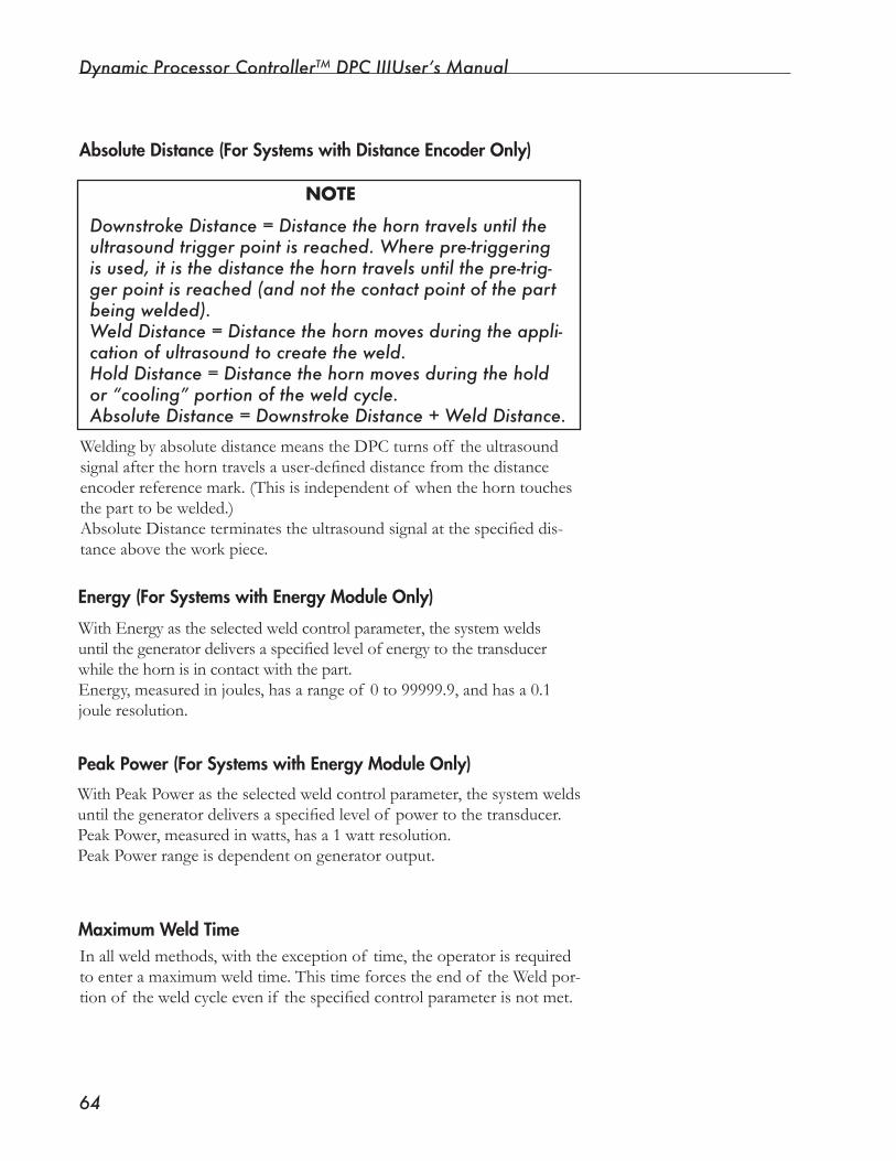
Dynamic Processor ControllerTM DPC IIIUser’s Manual
��
Absolute Distance (For Systems with Distance Encoder Only)
NOTE
Downstroke Distance = Distance the horn travels until the ultrasound trigger point is reached. Where pre-triggering is used, it is the distance the horn travels until the pre-trig-ger point is reached (and not the contact point of the part being welded).Weld Distance = Distance the horn moves during the appli-cation of ultrasound to create the weld.Hold Distance = Distance the horn moves during the hold or “cooling” portion of the weld cycle.Absolute Distance = Downstroke Distance + Weld Distance.
Welding by absolute distance means the DPC turns off the ultrasound signalafterthehorntravelsauser-defineddistancefromthedistanceencoderreferencemark.(Thisisindependentof whenthehorntouchestheparttobewelded.)AbsoluteDistanceterminatestheultrasoundsignalatthespecifieddis-tanceabovetheworkpiece.
Energy (For Systems with Energy Module Only)
WithEnergyastheselectedweldcontrolparameter,thesystemweldsuntilthegeneratordeliversaspecifiedlevelofenergytothetransducerwhilethehornisincontactwiththepart.Energy, measured in joules, has a range of 0 to 99999.9, and has a 0.1 joule resolution.
Peak Power (For Systems with Energy Module Only)
WithPeakPowerastheselectedweldcontrolparameter,thesystemweldsuntilthegeneratordeliversaspecifiedlevelof powertothetransducer.PeakPower,measuredinwatts,hasa1wattresolution.PeakPowerrangeisdependentongeneratoroutput.
Maximum Weld TimeInallweldmethods,withtheexceptionof time,theoperatorisrequiredtoenteramaximumweldtime.Thistimeforcestheendof theWeldpor-tionof theweldcycleevenif thespecifiedcontrolparameterisnotmet.
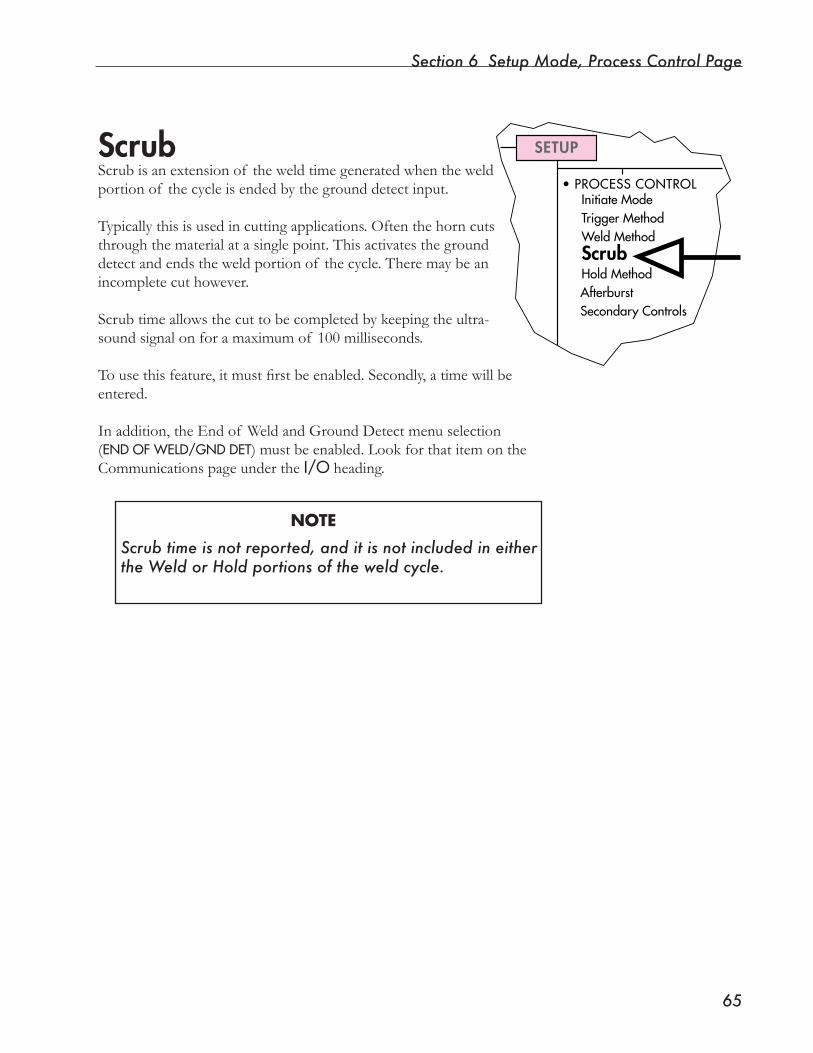
Section 6 Setup Mode, Process Control Page
��
SETUP
•PROCESSCONTROLInitiateModeTriggerMethodWeldMethodScrubHoldMethodAfterburstSecondaryControls
ScrubScrubisanextensionof theweldtimegeneratedwhentheweldportion of the cycle is ended by the ground detect input.
Typically this is used in cutting applications. Often the horn cuts through the material at a single point. This activates the ground detectandendstheweldportionof thecycle.Theremaybeanincompletecuthowever.
Scrubtimeallowsthecuttobecompletedbykeepingtheultra-sound signal on for a maximum of 100 milliseconds.
Tousethisfeature,itmustfirstbeenabled.Secondly,atimewillbeentered.
In addition, the End of Weld and Ground Detect menu selection (ENDOFWELD/GNDDET) must be enabled. Look for that item on the Communications page under the I/O heading.
NOTE
Scrub time is not reported, and it is not included in either the Weld or Hold portions of the weld cycle.
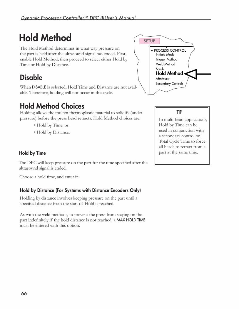
Dynamic Processor ControllerTM DPC IIIUser’s Manual
��
SETUP
•PROCESSCONTROLInitiateModeTriggerMethodWeldMethodScrubHold MethodAfterburstSecondaryControls
Hold MethodTheHoldMethoddeterminesinwhatwaypressureonthe part is held after the ultrasound signal has ended. First, enable Hold Method; then proceed to select either Hold by Time or Hold by Distance.
Hold Method ChoicesHoldingallowsthemoltenthermoplasticmaterialtosolidify(underpressure)beforethepressheadretracts.HoldMethodchoicesare:
• Hold by Time, or
• Hold by Distance.
Choose a hold time, and enter it.
Hold by Time
TheDPCwillkeeppressureonthepartforthetimespecifiedaftertheultrasound signal is ended.
Hold by Distance (For Systems with Distance Encoders Only)
DisableWhen DISABLEis selected, Hold Time and Distance are not avail-able.Therefore,holdingwillnotoccurinthiscycle.
In multi-head applications, Hold by Time can be usedinconjunctionwitha secondary control on Total Cycle Time to force all heads to retract from a part at the same time.
TIP
Holding by distance involves keeping pressure on the part until a specifieddistancefromthestartof Holdisreached.
Aswiththeweldmethods,topreventthepressfromstayingonthepartindefinitelyif theholddistanceisnotreached,aMAXHOLDTIME mustbeenteredwiththisoption.
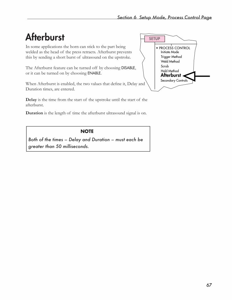
Section 6 Setup Mode, Process Control Page
��
SETUP
•PROCESSCONTROLInitiateModeTriggerMethodWeldMethodScrubHoldMethodAfterburstSecondaryControls
AfterburstIn some applications the horn can stick to the part being weldedastheheadof thepressretracts.Afterburstpreventsthis by sending a short burst of ultrasound on the upstroke.
The Afterburst feature can be turned off by choosing DISABLE, or it can be turned on by choosing ENABLE.
WhenAfterburstisenabled,thetwovaluesthatdefineit,DelayandDuration times, are entered.
Delay is the time from the start of the upstroke until the start of the afterburst.
Duration is the length of time the afterburst ultrasound signal is on.
NOTE
Both of the times – Delay and Duration – must each be greater than 50 milliseconds.
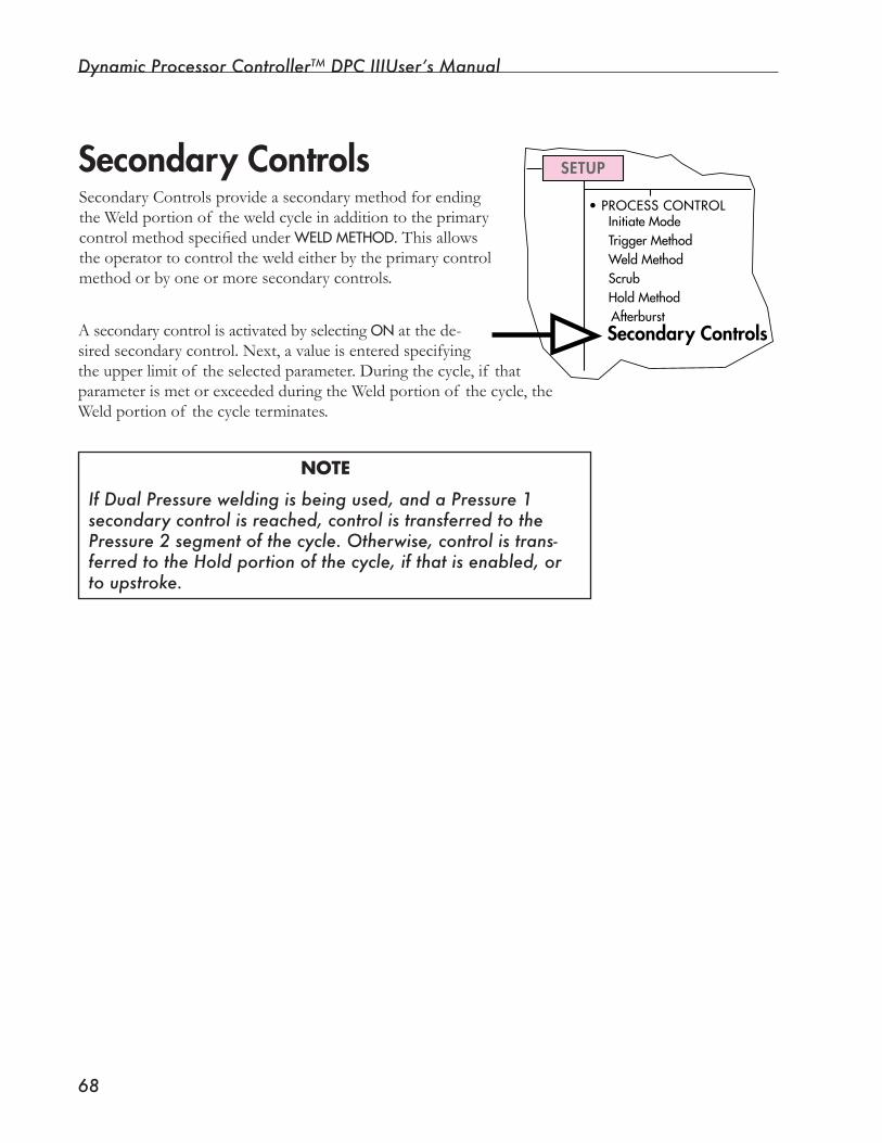
Dynamic Processor ControllerTM DPC IIIUser’s Manual
��
SETUP
•PROCESSCONTROLInitiateModeTriggerMethodWeldMethodScrubHoldMethodAfterburstSecondary Controls
Secondary Controls
A secondary control is activated by selecting ONat the de-sired secondary control. Next, a value is entered specifying the upper limit of the selected parameter. During the cycle, if that parameter is met or exceeded during the Weld portion of the cycle, the Weld portion of the cycle terminates.
NOTE
If Dual Pressure welding is being used, and a Pressure 1 secondary control is reached, control is transferred to the Pressure 2 segment of the cycle. Otherwise, control is trans-ferred to the Hold portion of the cycle, if that is enabled, or to upstroke.
Secondary Controls provide a secondary method for ending theWeldportionof theweldcycleinadditiontotheprimarycontrolmethodspecifiedunderWELDMETHOD.Thisallowstheoperatortocontroltheweldeitherbytheprimarycontrolmethod or by one or more secondary controls.

SECTION 7
Setup Mode, Process Limits Page• This section describes process characteristics and showshowtoestablishlimitsforthem.
Dukane Corporation

Dynamic Processor ControllerTM DPC III Plus User’s Manual
This page intentionally left blank
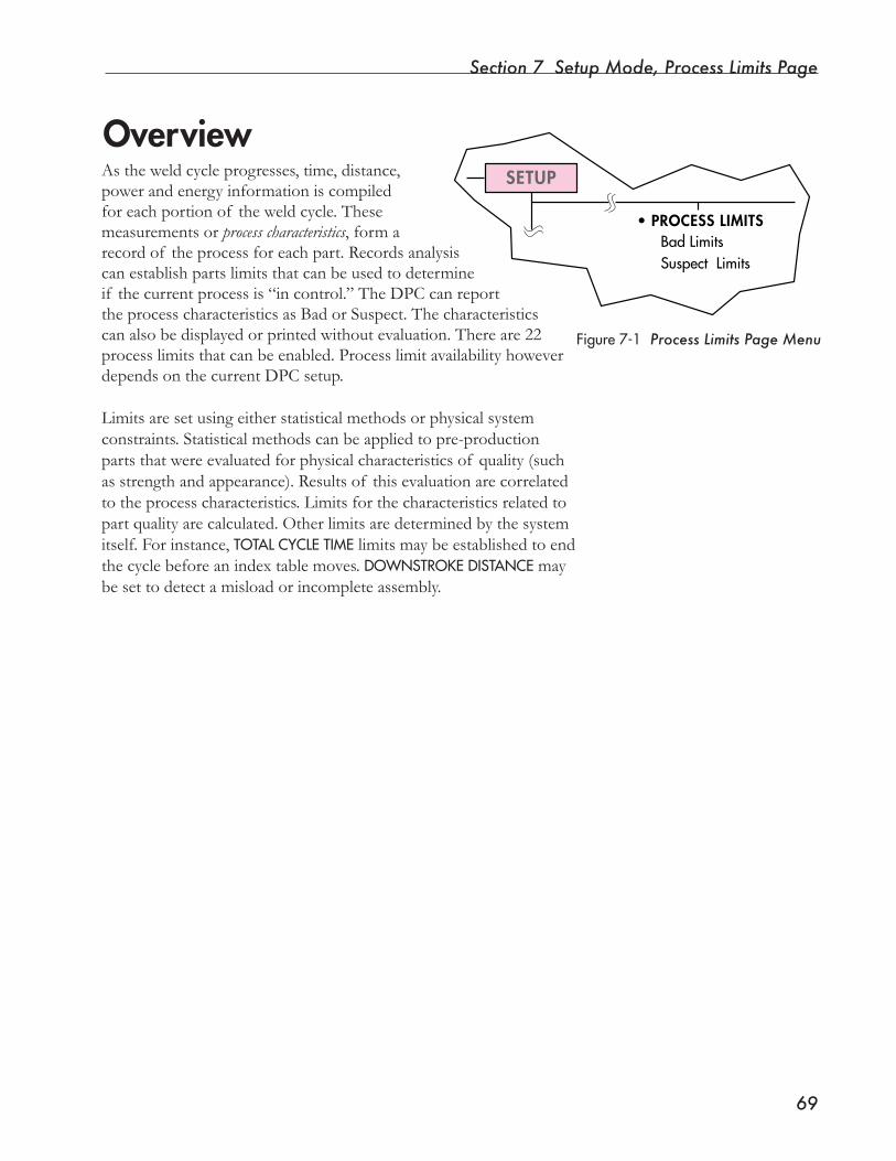
Section 7 Setup Mode, Process Limits Page
��
SETUP
•PROCESS LIMITSBadLimitsSuspectLimits
OverviewAstheweldcycleprogresses,time,distance,powerandenergyinformationiscompiledforeachportionof theweldcycle.Thesemeasurements or process characteristics, form a record of the process for each part. Records analysis can establish parts limits that can be used to determine if the current process is “in control.” The DPC can report the process characteristics as Bad or Suspect. The characteristics canalsobedisplayedorprintedwithoutevaluation.Thereare22processlimitsthatcanbeenabled.Processlimitavailabilityhoweverdepends on the current DPC setup.
Limits are set using either statistical methods or physical system constraints. Statistical methods can be applied to pre-production partsthatwereevaluatedforphysicalcharacteristicsof quality(suchas strength and appearance). Results of this evaluation are correlated to the process characteristics. Limits for the characteristics related to part quality are calculated. Other limits are determined by the system itself. For instance, TOTALCYCLETIME limits may be established to end the cycle before an index table moves. DOWNSTROKEDISTANCE may be set to detect a misload or incomplete assembly.
Figure7-1 Process Limits Page Menu
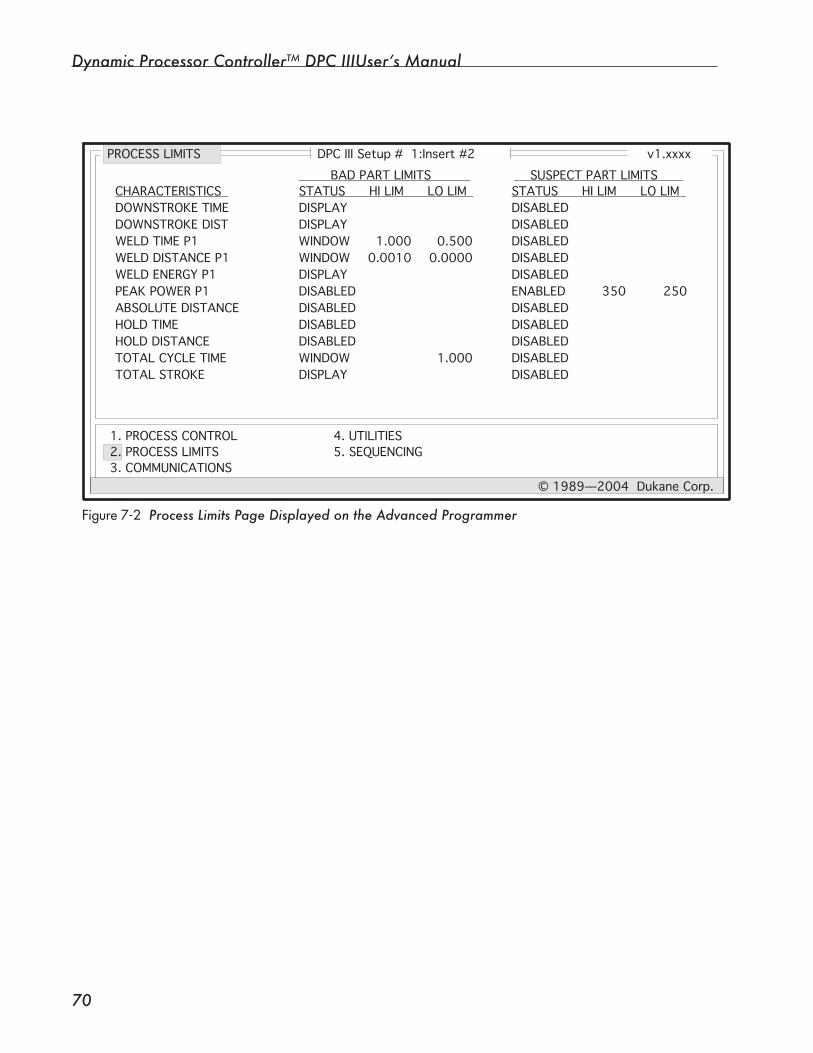
Dynamic Processor ControllerTM DPC IIIUser’s Manual
�0
Figure7-2 Process Limits Page Displayed on the Advanced Programmer
DPC III Setup # 1:Insert #2 v1.xxxx
1. PROCESS CONTROL2. PROCESS LIMITS3. COMMUNICATIONS
4. UTILITIES5. SEQUENCING
© 1989—2004 Dukane Corp.
DOWNSTROKE TIMEDOWNSTROKE DISTWELD TIME P1WELD DISTANCE P1WELD ENERGY P1PEAK POWER P1ABSOLUTE DISTANCEHOLD TIMEHOLD DISTANCETOTAL CYCLE TIMETOTAL STROKE
CHARACTERISTICS BAD PART LIMITS SUSPECT PART LIMITS STATUS HI LIM LO LIM STATUS HI LIM LO LIMDISPLAYDISPLAYWINDOWWINDOWDISPLAYDISABLEDDISABLEDDISABLEDDISABLEDWINDOWDISPLAY
1.0000.0010
0.5000.0000
1.000
DISABLEDDISABLEDDISABLEDDISABLEDDISABLEDENABLEDDISABLEDDISABLEDDISABLEDDISABLEDDISABLED
350 250
PROCESS LIMITS
Section 7 Setup Mode, Process Limits Page
��
Continued
Available Process CharacteristicsNOTE
Of the available process characteristics, the ones that apply to a particular part depend on the current DPC setup for
Hereisalistof theavailableprocesscharacteristicsfollowedbybrief descriptions of each.
Process Characteristics DefinedDownstroke Time–Thisisthetimefromthestartof theweldcycle(closingof theAutoInputormanualactivationswitches)tothetriggerpoint.Triggerpointiseithertheclosingof thetriggerswitchorthepre-trigger point if STARTWELDATisdefinedasPRE-TRIGGER.DownstrokeTimeisavailableinalltriggermodesexceptProbe.
Downstroke Distance (Distance Encoder Systems Only) – This is the distancebetweenthedistanceencoderreferencemarkandthetriggerpoint. This limit is available in all trigger modes except for the Probe mode.
1.DownstrokeTime
2.DownstrokeDistance
3. Trigger Delay Time
4. Trigger Delay Distance
5. Weld Time P1
6. Weld Distance P1
7.WeldEnergyP1
8.PeakPowerP1
9. Weld Time P2
10. Weld Distance P2
11. Weld Energy P2
12.PeakPowerP2
13. Absolute Distance
14. Total Weld Time
15. Total Weld Distance
16. Total Weld Energy
17.HoldTime
18. Hold Distance
19. Total Cycle Time
20. Total Stroke
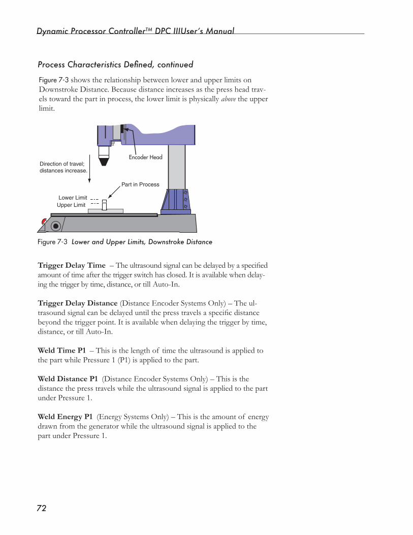
Dynamic Processor ControllerTM DPC IIIUser’s Manual
��
Encoder Head
Lower LimitUpper Limit
Direction of travel;distances increase.
Part in Process
Linear Encoder ScaleProcess Characteristics Defined, continued
Figure7-3 Lower and Upper Limits, Downstroke Distance
Figure7-3showstherelationshipbetweenlowerandupperlimitsonDownstrokeDistance.Becausedistanceincreasesasthepressheadtrav-elstowardthepartinprocess,thelowerlimitisphysicallyabove the upper limit.
Trigger Delay Time –Theultrasoundsignalcanbedelayedbyaspecifiedamountoftimeafterthetriggerswitchhasclosed.Itisavailablewhendelay-ing the trigger by time, distance, or till Auto-In.
Trigger Delay Distance (Distance Encoder Systems Only) – The ul-trasoundsignalcanbedelayeduntilthepresstravelsaspecificdistancebeyondthetriggerpoint.Itisavailablewhendelayingthetriggerbytime,distance, or till Auto-In.
Weld Time P1 – This is the length of time the ultrasound is applied to thepartwhilePressure1(P1)isappliedtothepart.
Weld Distance P1 (Distance Encoder Systems Only) – This is the distancethepresstravelswhiletheultrasoundsignalisappliedtothepartunder Pressure 1.
Weld Energy P1 (Energy Systems Only) – This is the amount of energy drawnfromthegeneratorwhiletheultrasoundsignalisappliedtothepart under Pressure 1.

Section 7 Setup Mode, Process Limits Page
��
Peak Power P1 (Energy Systems Only) – This is the highest in-stantaneouspowerdeliveredtothetransducerduringthePressure1portionof theweldcycle.
Weld Time P2 – This is the length of time the ultrasound is applied tothepartwhilePressure2(P2)isappliedtothepart.
Weld Distance P2 (Distance Encoder Systems Only) – This is the distancethepresstravelswhiletheultrasoundsignalisappliedtothepart under Pressure 2.
Weld Energy P2 (Energy Systems Only) – This is the amount of energydrawnfromthegeneratorwhiletheultrasoundsignalisap-plied to the part under Pressure 2.
Peak Power P2 (Energy Systems Only) – This is the highest in-stantaneouspowerdeliveredtothetransducerduringthePressure2portionof theweldcycle.
Absolute Distance (Distance Encoder Systems Only) – This is the user-defineddistancethehorntravelsfromthedistanceencoderref-erencemark(regardlessof whenthehorncontactsthepart).
Total Weld Time–Thisisavailablewhendualpressureweldingisselected.Itisthetotalof P1andP2weldtimes.
Total Weld Distance (Distance Encoder Systems Only) – This is availablewhendualpressureweldingisselected.Itisthetotalof P1andP2welddistances.
Total Weld Energy (EnergySystemsOnly)–Thisisavailablewhendualpressureweldingisselected.Itisthesumof thePressure1andPressure2weldenergies.
Continued
Dynamic Processor ControllerTM DPC IIIUser’s Manual
��
Hold Time – This is the time the horn maintains pressure on the part aftertheultrasoundsignalhasstopped,andwhilePressure2isappliedtothe part.
NOTE
This characteristic is available when the Hold Method setup item on the Process Control Page is Enabled, and Hold by
Process Characteristics Defined, continued
Hold Distance (Distance Encoder Systems Only) – This is the distance thepresstravelswhilemaintainingPressure2onthepartaftertheultra-sound signal has stopped.
Total Cycle Time – This is the time from Cycle Initiate through the Hold portion of the cycle. (See Figure6-5, Page 58.) The start of the cycle isdefinedasthepointtheautoinputsignalbeginsorwhenmanualacti-vationswitchesareclosed.Theendof thecycleisdefinedasthepointthe head retracts from the part.
Total Stroke (Distance Encoder Systems Only) – This is the absolute press position as measured from the distance encoder reference mark. It is active during the entire cycle.
NOTEThis characteristic is available when the Hold Method setup item on the Process Control Page is enabled and Hold by Distance is selected.
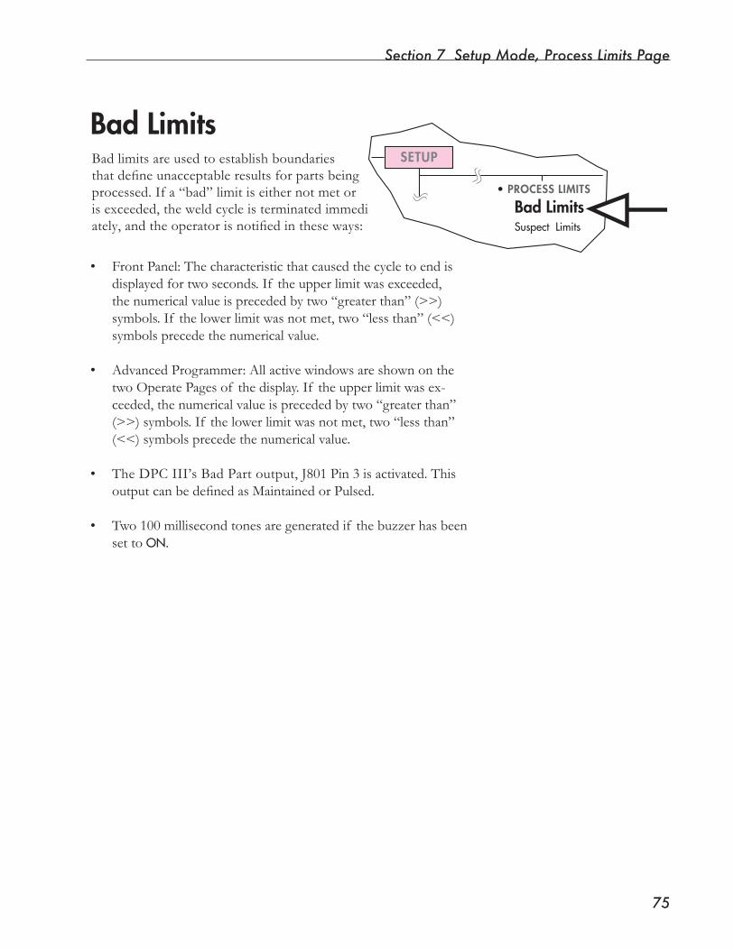
Section 7 Setup Mode, Process Limits Page
��
Bad LimitsBad limits are used to establish boundaries thatdefineunacceptableresultsforpartsbeingprocessed. If a “bad” limit is either not met or isexceeded,theweldcycleisterminatedimmedi-ately,andtheoperatorisnotifiedintheseways:
• FrontPanel:Thecharacteristicthatcausedthecycletoendisdisplayedfortwoseconds.If theupperlimitwasexceeded,thenumericalvalueisprecededbytwo“greaterthan”(>>)symbols.If thelowerlimitwasnotmet,two“lessthan”(<<)symbols precede the numerical value.
• AdvancedProgrammer:AllactivewindowsareshownonthetwoOperatePagesof thedisplay.If theupperlimitwasex-ceeded,thenumericalvalueisprecededbytwo“greaterthan”(>>)symbols.If thelowerlimitwasnotmet,two“lessthan”(<<)symbolsprecedethenumericalvalue.
• The DPC III’s Bad Part output, J801 Pin 3 is activated. This outputcanbedefinedasMaintainedorPulsed.
• Two100millisecondtonesaregeneratedif thebuzzerhasbeenset to ON.
SETUP
• PROCESS LIMITS
Bad LimitsSuspect Limits
Dynamic Processor ControllerTM DPC IIIUser’s Manual
��
Bad Limits Status FieldTherearethreeavailableselectionsfortheBadLimitsstatusfield:Disabled,Display,andWindow.
Disabled
When a process characteristic is disabled, it is not evaluated as a limit and is not displayed unless it is selected as a suspect limit. DISABLEDis the default selection.
Display
The DISPLAYselectionallowsthecharacteristictobedisplayedontheFront Panel and on the Advanced Programmer displays. DISPLAYalso enables a characteristic to be sent to an output device (such as a printer or a computer).
Window
The Bad Limits WINDOWchoiceassignsupperandlowerlimitstoachar-acteristic. The upper limit is tested continuously during the segment in whichthecharacteristicisactive.Thelowerlimitistestedonlyattheendof the active segment.
Forexample,whenintheWeldportionof thecycle,theupperlimitonWeld Distance is tested from the start to the end of the Weld segment. ThelowerlimitonWeldDistanceistestedonlyattheendof theWeldsegment. Figure7-2showsWeldTimeP1setasawindow.
IfacharacteristicisenabledasaWindowand as a Secondary Control, the upper bad limit is not available on the Process Limits Page.
A secondary control is designed to pass control of the process to the next segmentoftheweldcyclewithoutevaluatingthepartbasedontheenabledcharacteristic.Therefore,placinganupperbadlimitwouldbeinconsistentgiventhewaysecondarycontrolsaredesigned.
Attempting to access the upper limit results in a W00:MAXLIMITCON-TROLPARAMETERwarningmessagedisplayedontheFrontPanelandAdvanced Programmer displays. Figure7-2showstheTotalCycleTimecharacteristicsetupasbothawindowandasasecondarycontrol.
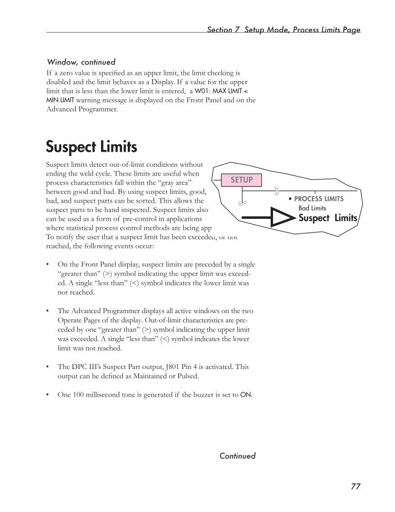
Section 7 Setup Mode, Process Limits Page
��
If azerovalueisspecifiedasanupperlimit,thelimitcheckingisdisabled and the limit behaves as a Display. If a value for the upper limitthatislessthanthelowerlimitisentered,aW01:MAXLIMIT<MINLIMITwarningmessageisdisplayedontheFrontPanelandontheAdvanced Programmer.
Window, continued
Suspect LimitsSuspectlimitsdetectout-of-limitconditionswithoutendingtheweldcycle.Theselimitsareusefulwhenprocesscharacteristicsfallwithinthe“grayarea”betweengoodandbad.Byusingsuspectlimits,good,bad,andsuspectpartscanbesorted.Thisallowsthesuspect parts to be hand inspected. Suspect limits also can be used as a form of pre-control in applications wherestatisticalprocesscontrolmethodsarebeingapplied.To notify the user that a suspect limit has been exceeded, or not reached,thefollowingeventsoccur:
• On the Front Panel display, suspect limits are preceded by a single “greaterthan”(>)symbolindicatingtheupperlimitwasexceed-ed.Asingle“lessthan”(<)symbolindicatesthelowerlimitwasnot reached.
• TheAdvancedProgrammerdisplaysallactivewindowsonthetwo
Operate Pages of the display. Out-of-limit characteristics are pre-cededbyone“greaterthan”(>)symbolindicatingtheupperlimitwasexceeded.Asingle“lessthan”(<)symbolindicatesthelowerlimitwasnotreached.
• The DPC III’s Suspect Part output, J801 Pin 4 is activated. This outputcanbedefinedasMaintainedorPulsed.
• One 100 millisecond tone is generated if the buzzer is set to ON.
Continued
SETUP
• PROCESS LIMITSBad Limits
Suspect Limits
Dynamic Processor ControllerTM DPC IIIUser’s Manual
��
Suspect Limits Status FieldTherearetwoavailableselectionsfortheSuspectLimitsstatusfield:Disabled or Enabled.
Disabled
If a suspect limit is disabled, it is not evaluated as a Suspect limit.
Enabled
Enablingasuspectlimitallowstheentryof upperandlowerSuspectlimits for the selected process characteristic. Suspect limits are tested at theendof thecycle.Thereforetheyhavenoeffectontheflowof theweldingprocess.AswithBadLimits,settingtheupperlimittozeroisthe same as specifying the limit as Display only. No evaluation of the limit is performed. Entering a value for the upper limit that is less that thelowerlimitresultsinaW01:MAXLIMIT<MINLIMITwarningmessagedisplayed on the Front Panel and on the Advanced Programmer.
Section 7 Setup Mode, Process Limits Page
��
Enabling Process LimitsNOTE
The status field controls the behavior of the character-istic both as a process limit and as a displayable pa-rameter. If either status field is not set to DISABLED, the characteristic is displayed on both the Front Panel and Advanced Programmer displays. It is also sent to the output device.
Enable process limits by starting on the Process Limits Page. Then do thefollowing:
1. Press the ENTERkey.
2. PresstheUporDownArrowkeystochoosebetweenBadLimitsand Suspect Limits. With the Advanced Programmer keyboard, the “1” and “2” number keys can also be used to make the choice.
3. Press the ENTERkey.
4. PresstheUporDownArrowkeystoselectaprocesscharacteris-tic.
5. Press the ENTERkey.
6. PresstheUporDownArrowkeys(orthe“1”,“2”,“3”numberkeys on the Advanced Programmer keyboard) to choose the Bad LimitsorSuspectLimitsstatusfieldselections.
7. PresstheENTERkey.
8. Repeatsteps4–7foreachprocesscharacteristicdesired.
Dynamic Processor ControllerTM DPC IIIUser’s Manual
�0
Secondary ControlSecondarycontrolsprovideadditionalwaystoendtheWeldportionof acycletogetherwiththeprimarycontrolmethodspecified.Thismeanscontrolof theweldprocesscanbeaccomplishedeitherbytheprimarycontrol or by one or more secondary controls.
Not All Characteristics Have Secondary ControlSecondarycontrolscanbeselectedforthefollowingprocesscharacteristics:
Weld Energy P1 PeakPowerP1 Weld Energy P2 PeakPowerP2 Absolute Distance Total Weld Time Total Weld Distance Total Weld Energy Total Cycle Time Total Stroke
EXAMPLE
If youareusingdualpressurewelding,andaP1secondarycontrollimitisreached,controlistransferredtotheP2portionof thecycle.Otherwise,control is transferred to the Hold portion of the cycle (if it is enabled) or to the Upstroke portion of the cycle.
SECTION 8
Setup Mode, Communications Page• ThissectiondescribeshowtheDPCIIIcanbesetuptocommunicatewithexternaldevices.
Dukane Corporation

Dynamic Processor ControllerTM DPC III Plus User’s Manual
This page intentionally left blank
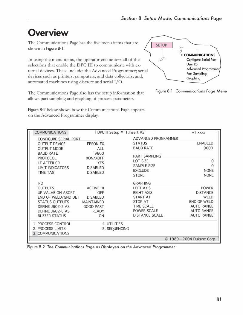
Section 8 Setup Mode, Communications Page
��
Overview
Figure8-1 Communications Page Menu
•COMMUNICATIONSConfigureSerialPortUserIOAdvancedProgrammerPartSamplingGraphing
SETUPTheCommunicationsPagehasthefivemenuitemsthatareshowninFigure8-1.
In using the menu items, the operator encounters all of the selectionsthatenabletheDPCIIItocommunicatewithex-ternaldevices.Theseinclude:theAdvancedProgrammer;serialdevices such as printers, computers, and data collectors; and, automated machines using discrete and serial I/O.
The Communications Page also has the setup information that allowspartsamplingandgraphingof processparameters.
Figure8-2belowshowshowtheCommunicationsPageappearson the Advanced Programmer display.
Figure8-2 The Communications Page as Displayed on the Advanced Programmer
DPC III Setup # 1:Insert #2 v1.xxxx
1. PROCESS CONTROL2. PROCESS LIMITS3. COMMUNICATIONS
4. UTILITIES5. SEQUENCING
© 1989—2004 Dukane Corp.
COMMUNICATIONS
OUTPUT DEVICEOUTPUT MODEBAUD RATEPROTOCOLLF AFTER CRLIMIT INDICATORSTIME TAG
OUTPUTSUP VALVE ON ABORTEND OF WELD/GND DETSTATUS OUTPUTSDEFINE J602-5 ASDEFINE J602-6 ASBUZZER STATUS
STATUS BAUD RATE
LOT SIZESAMPLE SIZEEXCLUDESTORE
LEFT AXISRIGHT AXISSTART ATSTOP ATTIME SCALEPOWER SCALEDISTANCE SCALE
EPSON-FXALL
9600XON/XOFF
YESDISABLEDDISABLED
ACTIVE HIOFF
DISABLEDMAINTAINEDGOOD PART
READYON
ENABLED9600
00
NONENONE
POWERDISTANCE
WELDEND OF WELDAUTO RANGEAUTO RANGEAUTO RANGE
CONFIGURE SERIAL PORT
I/O
ADVANCED PROGRAMMER
PART SAMPLING
GRAPHING
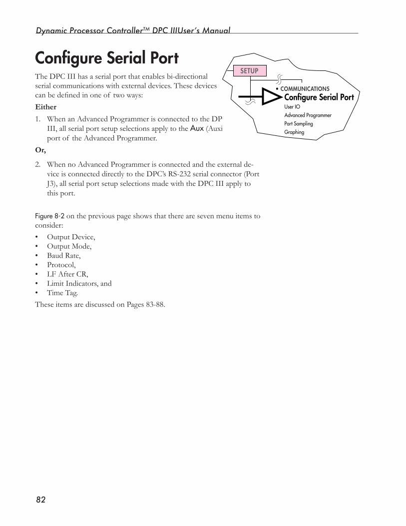
Dynamic Processor ControllerTM DPC IIIUser’s Manual
��
Configure Serial PortThe DPC III has a serial port that enables bi-directional serialcommunicationswithexternaldevices.Thesedevicescanbedefinedinoneof twoways:
Either
1. When an Advanced Programmer is connected to the DPC III, all serial port setup selections apply to the Aux (Auxiliary) port of the Advanced Programmer.
Or,
2. When no Advanced Programmer is connected and the external de-vice is connected directly to the DPC’s RS-232 serial connector (Port J3),allserialportsetupselectionsmadewiththeDPCIIIapplytothis port.
Figure8-2onthepreviouspageshowsthattherearesevenmenuitemstoconsider:• Output Device,• Output Mode,• Baud Rate,• Protocol,• LF After CR,• Limit Indicators, and• Time Tag.These items are discussed on Pages 83-88.
•COMMUNICATIONSConfigure Serial PortUserIOAdvancedProgrammerPartSamplingGraphing
SETUP
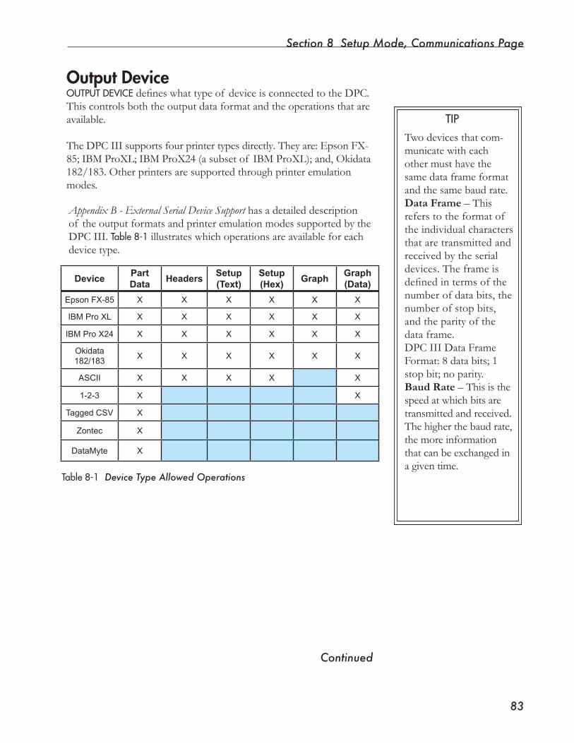
Section 8 Setup Mode, Communications Page
��
Output DeviceOUTPUTDEVICEdefineswhattypeof deviceisconnectedtotheDPC.This controls both the output data format and the operations that are available.
TheDPCIIIsupportsfourprintertypesdirectly.Theyare:EpsonFX-85; IBM ProXL; IBM ProX24 (a subset of IBM ProXL); and, Okidata 182/183. Other printers are supported through printer emulation modes.
Appendix B - External Serial Device Support has a detailed description of the output formats and printer emulation modes supported by the DPC III. Table8-1illustrateswhichoperationsareavailableforeachdevice type.
TIP
Table8-1 Device Type Allowed Operations
Twodevicesthatcom-municatewitheachother must have the same data frame format and the same baud rate.Data Frame – This refers to the format of the individual characters that are transmitted and received by the serial devices. The frame is definedintermsofthenumber of data bits, the number of stop bits, and the parity of the data frame.DPC III Data Frame Format:8databits;1stop bit; no parity.Baud Rate – This is the speedatwhichbitsaretransmitted and received. The higher the baud rate, the more information that can be exchanged in a given time.
Continued
DevicePart Data
HeadersSetup(Text)
Setup(Hex)
GraphGraph(Data)
Epson FX-85 X X X X X X
IBM Pro XL X X X X X X
IBM Pro X24 X X X X X X
Okidata 182/183
X X X X X X
ASCII X X X X X
1-2-3 X X
Tagged CSV X
Zontec X
DataMyte X
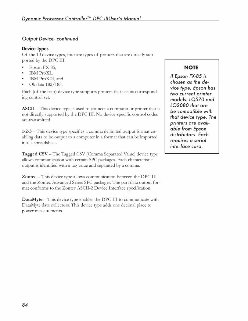
Dynamic Processor ControllerTM DPC IIIUser’s Manual
��
Device TypesOf the 10 device types, four are types of printers that are directly sup-portedbytheDPCIII:• Epson FX-85,• IBM ProXL,• IBM ProX24, and• Okidata 182/183.Each (of the four) device type supports printers that use its correspond-ing control set.
ASCII – This device type is used to connect a computer or printer that is notdirectlysupportedbytheDPCIII.Nodevice-specificcontrolcodesare transmitted.
1-2-3–Thisdevicetypespecifiesacommadelimitedoutputformaten-abling data to be output to a computer in a format that can be imported into a spreadsheet.
Tagged CSV – The Tagged CSV (Comma Separated Value) device type allowscommunicationwithcertainSPCpackages.Eachcharacteristicoutputisidentifiedwithatagvalueandseparatedbyacomma.
Zontec–ThisdevicetypeallowscommunicationbetweentheDPCIIIand the Zontec Advanced Series SPC packages. The part data output for-matconformstotheZontecASCII-2DeviceInterfacespecification.
DataMyte–ThisdevicetypeenablestheDPCIIItocommunicatewithDataMyte data collectors. This device type adds one decimal place to powermeasurements.
Output Device, continued
NOTE
If Epson FX-�� is chosen as the de-vice type, Epson has two current printer models: LQ��0 and LQ�0�0 that are be compatible with that device type. The printers are avail-able from Epson distributors. Each requires a serial interface card.
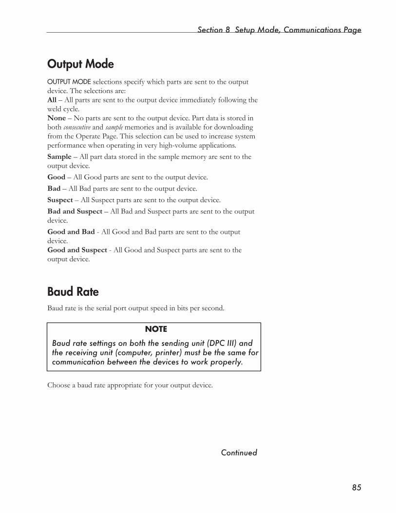
Section 8 Setup Mode, Communications Page
��
Output ModeOUTPUTMODEselectionsspecifywhichpartsaresenttotheoutputdevice.Theselectionsare:All –Allpartsaresenttotheoutputdeviceimmediatelyfollowingtheweldcycle.None – No parts are sent to the output device. Part data is stored in both consecutive and samplememoriesandisavailablefordownloadingfrom the Operate Page. This selection can be used to increase system performancewhenoperatinginveryhigh-volumeapplications.Sample – All part data stored in the sample memory are sent to the output device.Good – All Good parts are sent to the output device.Bad – All Bad parts are sent to the output device.Suspect – All Suspect parts are sent to the output device.Bad and Suspect – All Bad and Suspect parts are sent to the output device.Good and Bad - All Good and Bad parts are sent to the output device.Good and Suspect - All Good and Suspect parts are sent to the output device.
Baud RateBaud rate is the serial port output speed in bits per second.
NOTE
Baud rate settings on both the sending unit (DPC III) and the receiving unit (computer, printer) must be the same for communication between the devices to work properly.
Choose a baud rate appropriate for your output device.
Continued
Dynamic Processor ControllerTM DPC IIIUser’s Manual
��
ProtocolProtocol refers to the programming rules established to ensure reliable communicationsbetweendevices.Inmanycases,therateatwhichadevice can transmit information to the second device exceeds the second device’s ability to process it.Wheninformationissenttoaprinter,therateatwhichtheprinterre-ceives and processes the information is much faster than its ability to print it.Eventually,theprinterwouldrunoutofstorage,orbufferspace.Thismeansthatanyexcessdatawouldbelost.The printer and the DPC III can provide acceptable transmission rate informationtoeachothertoregulatetheflowof databetweenthem.
ThetwomethodsusedbytheDPCIIItocontrolthisinformationflowrateareXon/Xoff andRTS/CTSasexplainedbelow:
Xon/XoffXon/Xoff isasoftwareprotocolregulatingtheflowof informationbetweentwodevicesbysendinganXoff character(13H,^S)tostoptheflowof informationandanXoncharacter(11H,^Q)toresumetheflowof information.
RTS/CTSRTS/CTSisahardwareprotocolthatusestwosignals(RTSandCTS)toregulatetheflowof informationbetweendevices.RequesttoSend(RTS)istransmittedwhenadevicehasinformationtosendtoaseconddevice.TheseconddeviceacknowledgestheRTSbysendingaCleartoSend(CTS)signalwhenitcansafelyacceptinforma-tion. If the second device’s capacity to accept information has been ex-ceeded, the CTS line is turned off until information can again be safely sent.
Configure Serial Port, continued
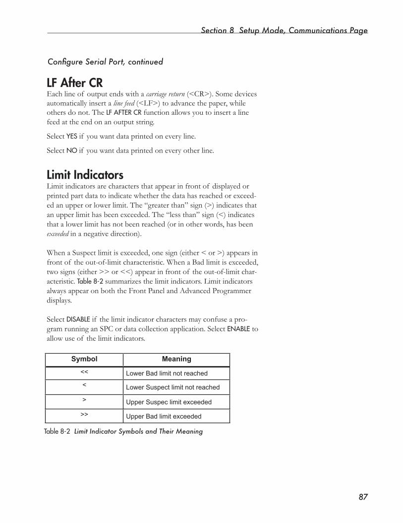
Section 8 Setup Mode, Communications Page
��
LF After CREachlineof outputendswithacarriage return(<CR>).Somedevicesautomatically insert a line feed(<LF>)toadvancethepaper,whileothers do not. The LFAFTERCRfunctionallowsyoutoinsertalinefeed at the end on an output string.
Select YESif youwantdataprintedoneveryline.
Select NOif youwantdataprintedoneveryotherline.
Limit IndicatorsLimit indicators are characters that appear in front of displayed or printedpartdatatoindicatewhetherthedatahasreachedorexceed-edanupperorlowerlimit.The“greaterthan”sign(>)indicatesthatanupperlimithasbeenexceeded.The“lessthan”sign(<)indicatesthatalowerlimithasnotbeenreached(orinotherwords,hasbeenexceeded in a negative direction).
WhenaSuspectlimitisexceeded,onesign(either<or>)appearsinfront of the out-of-limit characteristic. When a Bad limit is exceeded, twosigns(either>>or<<)appearinfrontof theout-of-limitchar-acteristic. Table8-2summarizes the limit indicators. Limit indicators alwaysappearonboththeFrontPanelandAdvancedProgrammerdisplays.
Select DISABLE if the limit indicator characters may confuse a pro-gram running an SPC or data collection application. Select ENABLE to allowuseof thelimitindicators.
Table8-2 Limit Indicator Symbols and Their Meaning
Configure Serial Port, continued
Symbol Meaning
<< Lower Bad limit not reached
< Lower Suspect limit not reached
> Upper Suspec limit exceeded
>> Upper Bad limit exceeded
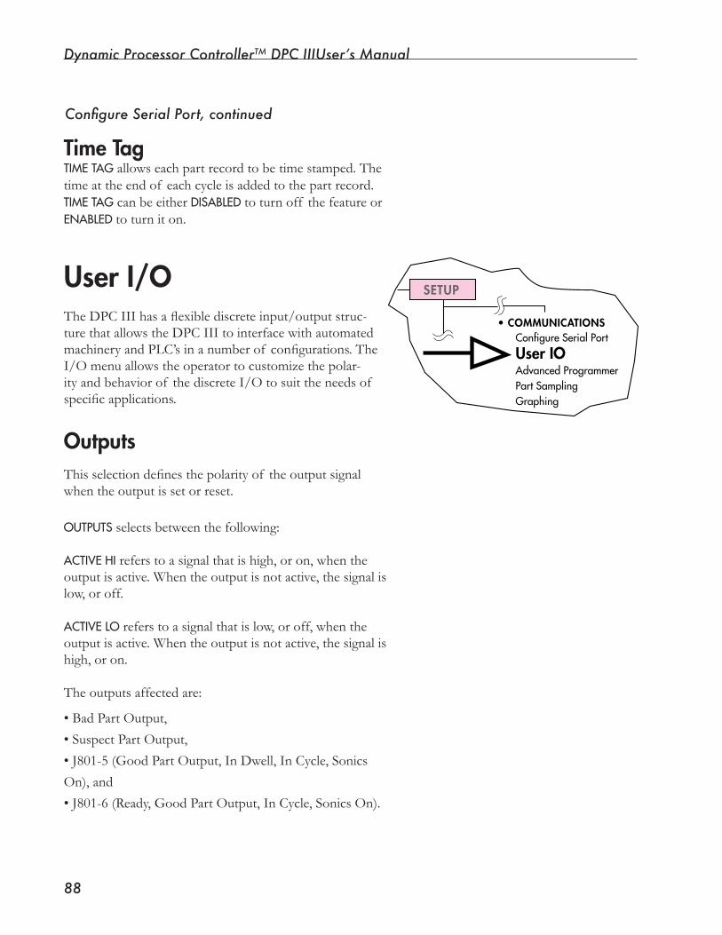
Dynamic Processor ControllerTM DPC IIIUser’s Manual
��
Time TagTIMETAGallowseachpartrecordtobetimestamped.Thetime at the end of each cycle is added to the part record. TIMETAG can be either DISABLEDto turn off the feature or ENABLEDto turn it on.
TheDPCIIIhasaflexiblediscreteinput/outputstruc-turethatallowstheDPCIIItointerfacewithautomatedmachineryandPLC’sinanumberof configurations.TheI/Omenuallowstheoperatortocustomizethepolar-ity and behavior of the discrete I/O to suit the needs of specificapplications.
OutputsThisselectiondefinesthepolarityof theoutputsignalwhentheoutputissetorreset.
OUTPUTSselectsbetweenthefollowing:
ACTIVEHIreferstoasignalthatishigh,oron,whentheoutput is active. When the output is not active, the signal is low,oroff.
ACTIVELOreferstoasignalthatislow,oroff,whentheoutput is active. When the output is not active, the signal is high, or on.
Theoutputsaffectedare:
• Bad Part Output,
• Suspect Part Output,
•J801-5(GoodPartOutput,InDwell,InCycle,Sonics
On), and
• J801-6 (Ready, Good Part Output, In Cycle, Sonics On).
User I/O •COMMUNICATIONS
ConfigureSerialPort
User IOAdvancedProgrammerPartSamplingGraphing
SETUP
Configure Serial Port, continued
Section 8 Setup Mode, Communications Page
��
UseActiveLowhenapositiveacknowledgmentof anoutputisneeded.
EXAMPLEConsiderasituationwheretheBadPartoutputisroutedtoaPLCthatcontrols a gate. The gate routes reject (Bad) parts to a reject part bin andshutsdowntheprocessiftwo“rejects”occurinarow.WithActiveHioutputs,abrokenwireorafailedoutputwouldpreventtherejectpartgatefromoperatingandwouldcauseBadpartstomixwithGoodparts.If,however,ActiveLooutputswereselectedandasystemfaultoccurred,thesignalwouldbelost,andthePLCwouldconsiderallpartsBad.Aftertwobadparts,thePLCwouldshutdowntheprocessandoutput an alarm. After determining that the DPC III produced Good parts, maintenance personnel could conduct tests to identify and correct the fault.
SwitchingtheOUTPUTS item from ACTIVEHI to AC-TIVELO, or vice versa, causes the above outputs to reset.
End of Weld/Ground DetectThis ENDOFWELDmenuitemdetermineswhethertheEndof Weld/Ground Detect inputs are recognized or ignored. Selecting DISABLEDmeanssignalswillbeignored.Selecting ENABLEDmeansthesignalswillberecognized.
TheEndof WeldinputisfromtheEndof WeldpresslimitflagandisusedtoendtheWeldportionof theweldcyclebasedontheposi-tionof thepresshead.Theflagcanbemanuallyraisedorloweredonthepresstoendtheweldatanabsolutedistance.
NOTE
This feature is generally not used with a press or thruster that has a distance encoder.
The Ground Detect input is located at the DPC III rear panel on Pin 15 of the J801 Auxiliary connector. Ground Detect is used in con-junctionwithScrub.RefertotheProcess Control Page for more infor-mation about Scrub.
Continued
Dynamic Processor ControllerTM DPC IIIUser’s Manual
�0
Status OutputsThisfeatureallowsaselectionof eitherMaintainedorPulsedpartstatusoutputs.Partstatusoutputsare:BadPartOut,SuspectPartOut,andGoodPartOut.MAINTAINED means that the outputs stay active until the start of the next weldcycle.PULSED means that outputs are active for 100 ms before being reset.
Define J801-5 AsPin5outputof theJ801Auxiliaryconnectorcanberedefinedasanyof thefollowing:
• Good Part,
• InDwell,
• In Cycle, or
• Sonics On.
Good PartTheGoodPartoutputisassertedwheneveraGoodpartismade.ItcanbeusedwiththeBadpartandSuspectpartoutputstodeterminepart status.
In DwellTheInDwelloutputisactivewhenevertheDPCIIIisinadelaypor-tionof theweldcycle.Delaysinclude:
• Trigger Delay by Time,
• Trigger Delay by Distance,
• Trigger Delay till Auto-In,
• Hold by Time, and
• Hold by Distance.
InDwellcanbeusedtodeterminewhereinthecurrentcyclethepro-cess is or it can be used to synchronize multiple DPC III’s in a multi-head application.
User I/O, continued
Section 8 Setup Mode, Communications Page
��
In CycleInCycleissetwhentheDPCIIIgoesintoaweldcycleandisresetatthe start of the Upstroke portion of the cycle.
Sonics OnSonicsOnoutputissetwhentheDPCIIIturnsontheultrasoundsignal. This is not a confirmation from the generator that the signal has fired. UsethePeakPowerprocesslimitstoverifygeneratoroperation.
Define J801-6 AsPin6outputof theJ801Auxiliaryconnectorcanberedefinedasanyof thefollowing:
• Ready,
• Good Part,
• In Cycle, and
• Sonics On.
ReadyReadyoutputissetwhenevertheDPCIIIisreadytogointothenext cycle. This means that the initiating signal from the last cycle has been cleared and that no inhibiting conditions exist. Inhibiting condi-tionsaredefinedas:• Cycle Start Input Active,• End of Weld Active,• Eitheroneorbothof theactivationswitchesActive,or• Auto Input Active from the last cycle.
If any inhibiting conditions exist, an error message appears on Front Panel and Advanced Programmer displays.
Good Part, In Cycle, and Sonics OnThe Good Part, In Cycle, and Sonics On outputs are identical to the DefineJ801-5menuitemdescribedabove.
Continued
NOTE
The Ready signal is not the same as the Top-of-Stroke position. See Page ��, Figure6-5.
Dynamic Processor ControllerTM DPC IIIUser’s Manual
��
Buzzer StatusUse BUZZERSTATUS to turn the DPC internal buzzer on or off.
ON
Thebuzzerwillsoundforeveryprocesscondition(suchaswhenaBador Suspect part limit has been exceeded).
OFFThebuzzerwillnotsoundforanyprocesscondition(suchaswhena
Bad or Suspect part limit has been exceeded).(ItwillsounditsnormaltonesduringtheDPCIIIstart-upsequencehowever.)
User I/O, continued
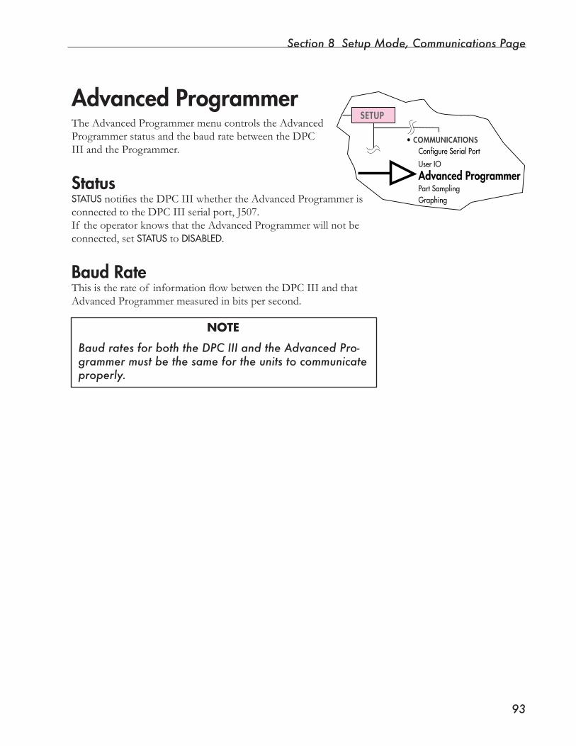
Section 8 Setup Mode, Communications Page
��
•COMMUNICATIONSConfigureSerialPort
UserIO
Advanced ProgrammerPartSamplingGraphing
SETUPAdvanced ProgrammerThe Advanced Programmer menu controls the Advanced ProgrammerstatusandthebaudratebetweentheDPCIII and the Programmer.
StatusSTATUSnotifiestheDPCIIIwhethertheAdvancedProgrammerisconnectedtotheDPCIIIserialport,J507.If theoperatorknowsthattheAdvancedProgrammerwillnotbeconnected, set STATUSto DISABLED.
Baud RateThisistherateof informationflowbetwentheDPCIIIandthatAdvanced Programmer measured in bits per second.
NOTE
Baud rates for both the DPC III and the Advanced Pro-grammer must be the same for the units to communicate properly.
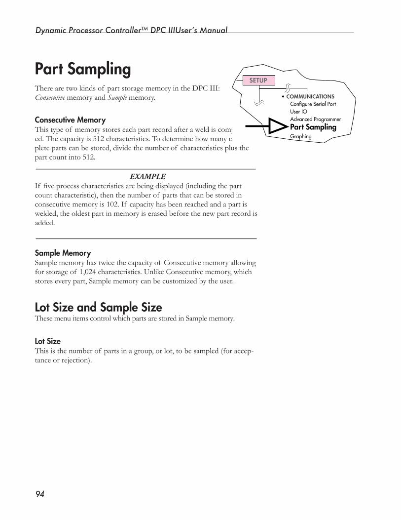
Dynamic Processor ControllerTM DPC IIIUser’s Manual
��
Part SamplingTherearetwokindsof partstoragememoryintheDPCIII:Consecutive memory and Sample memory.
Consecutive MemoryThistypeof memorystoreseachpartrecordafteraweldiscomplet-ed.Thecapacityis512characteristics.Todeterminehowmanycom-plete parts can be stored, divide the number of characteristics plus the part count into 512.
EXAMPLEIf fiveprocesscharacteristicsarebeingdisplayed(includingthepartcount characteristic), then the number of parts that can be stored in consecutive memory is 102. If capacity has been reached and a part is welded,theoldestpartinmemoryiserasedbeforethenewpartrecordisadded.
Sample MemorySamplememoryhastwicethecapacityof Consecutivememoryallowingforstorageof 1,024characteristics.UnlikeConsecutivememory,whichstores every part, Sample memory can be customized by the user.
Lot Size and Sample SizeThesemenuitemscontrolwhichpartsarestoredinSamplememory.
Lot SizeThis is the number of parts in a group, or lot, to be sampled (for accep-tance or rejection).
•COMMUNICATIONSConfigureSerialPortUserIOAdvancedProgrammer
Part SamplingGraphing
SETUP
Section 8 Setup Mode, Communications Page
��
Sample Size
This is the number of parts from the lot to be sampled.
If the Lot Size is set at 100 and the Sample Size is set at 5, then the followingpartswouldbestoredinSamplememory:
96,97,98,99,100 196,197,198,199,200 296,297,298,299,300 etc. . .
Samplingallowsqualityassurancepersonneltoautomaticallysamplepart data over a period of time so that the data can be collected once rather than several times per shift.
NOTE
If either LotSize or SampleSize is set to zero, or they are set to the same number, all parts are sampled automati-cally. Sample memory contains consecutive part records.
Part Sampling, continued
Continued
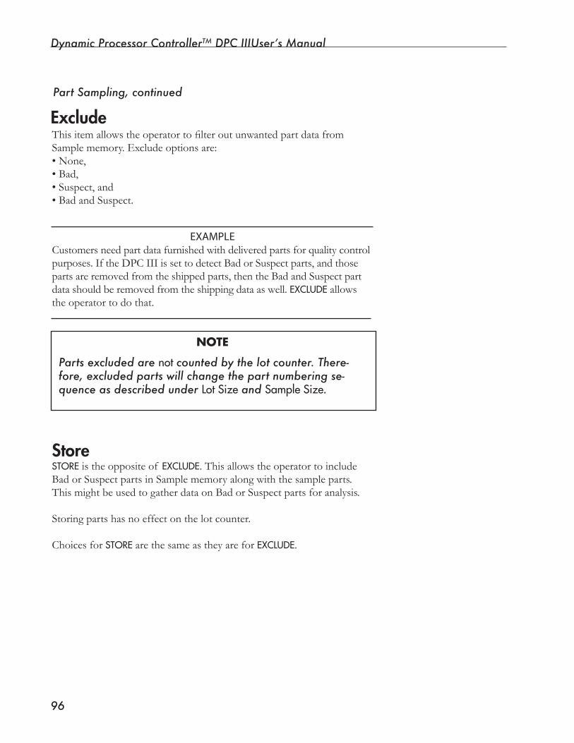
Dynamic Processor ControllerTM DPC IIIUser’s Manual
��
ThisitemallowstheoperatortofilteroutunwantedpartdatafromSamplememory.Excludeoptionsare:• None,• Bad,• Suspect, and• Bad and Suspect.
EXAMPLECustomersneedpartdatafurnishedwithdeliveredpartsforqualitycontrolpurposes. If the DPC III is set to detect Bad or Suspect parts, and those parts are removed from the shipped parts, then the Bad and Suspect part datashouldberemovedfromtheshippingdataaswell.EXCLUDEallowsthe operator to do that.
NOTE
Parts excluded are notcounted by the lot counter. There-fore, excluded parts will change the part numbering se-quence as described under LotSize and SampleSize.
StoreSTORE is the opposite of EXCLUDE.ThisallowstheoperatortoincludeBadorSuspectpartsinSamplememoryalongwiththesampleparts.This might be used to gather data on Bad or Suspect parts for analysis.
Storing parts has no effect on the lot counter.
Choices for STOREare the same as they are for EXCLUDE.
Part Sampling, continued
Exclude
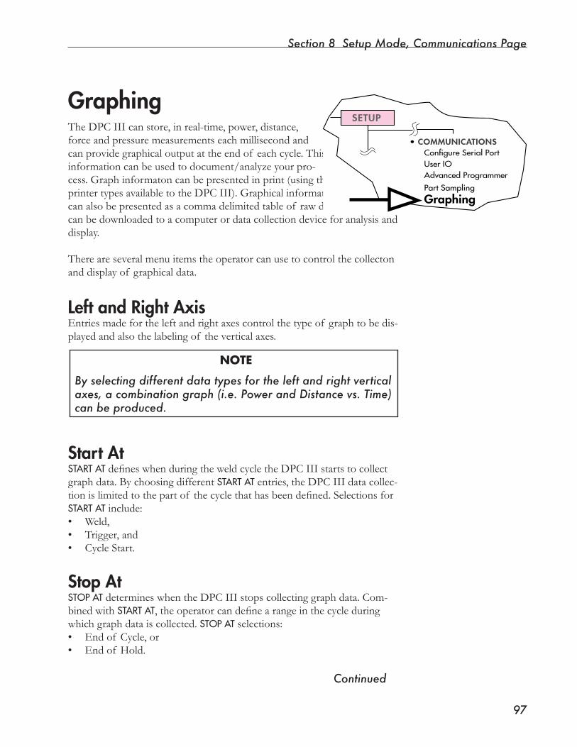
Section 8 Setup Mode, Communications Page
��
GraphingTheDPCIIIcanstore,inreal-time,power,distance,force and pressure measurements each millisecond and can provide graphical output at the end of each cycle. This information can be used to document/analyze your pro-cess. Graph informaton can be presented in print (using the printer types available to the DPC III). Graphical information canalsobepresentedasacommadelimitedtableof rawdatathatcanbedownloadedtoacomputerordatacollectiondeviceforanalysisanddisplay.
There are several menu items the operator can use to control the collecton and display of graphical data.
Left and Right AxisEntries made for the left and right axes control the type of graph to be dis-played and also the labeling of the vertical axes.
NOTE
By selecting different data types for the left and right vertical axes, a combination graph (i.e. Power and Distance vs. Time) can be produced.
Start AtSTARTATdefineswhenduringtheweldcycletheDPCIIIstartstocollectgraph data. By choosing different STARTAT entries, the DPC III data collec-tionislimitedtothepartof thecyclethathasbeendefined.SelectionsforSTARTATinclude:• Weld,• Trigger, and• Cycle Start.
Stop AtSTOPATdetermineswhentheDPCIIIstopscollectinggraphdata.Com-binedwithSTARTAT,theoperatorcandefinearangeinthecycleduringwhichgraphdataiscollected.STOPATselections:• End of Cycle, or• End of Hold.
•COMMUNICATIONSConfigureSerialPortUserIOAdvancedProgrammer
PartSampling
Graphing
SETUP
Continued

Dynamic Processor ControllerTM DPC IIIUser’s Manual
��
As the DPC III prepares to print a graph, the scale for each graph parameter is calculated based on that parameter’s maximum value. This is refered to as Auto Ranging. When the graphs are printed, the change in scale caused by Auto Rangingcanmakecomparisonof graphsdifficult.Toalleviatethisproblem,Time,Distance,andPowergraphshaveuser-select-ablescales.Selectingafixedscaleensuresthatgraphsappearconsistentfromcycle to cycle.
NOTE
Power and Distance scales can be changed between multiple graphs of the same part, but the Time scale cannot be changed.
Selecting Time, Power, and Distance Scales Graphing, continued

SECTION 9
Setup Mode, Utilities Page• ThissectiondescribeshowtheUtilitiesmenu
item can be used for setup management and for diagnostic tools..
Dukane Corporation

Dynamic Processor ControllerTM DPC III Plus User’s Manual
This page intentionally left blank
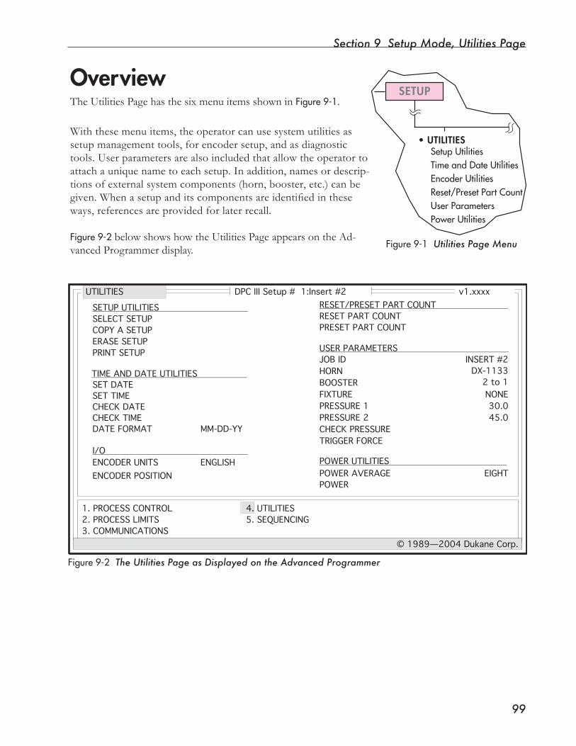
Section 9 Setup Mode, Utilities Page
��
SETUP
• UTILITIESSetup UtilitiesTime and Date UtilitiesEncoder UtilitiesReset/Preset Part CountUser ParametersPower Utilities
Overview
Figure9-1 Utilities Page Menu
TheUtilitiesPagehasthesixmenuitemsshowninFigure9-1. With these menu items, the operator can use system utilities as setup management tools, for encoder setup, and as diagnostic tools.Userparametersarealsoincludedthatallowtheoperatortoattach a unique name to each setup. In addition, names or descrip-tions of external system components (horn, booster, etc.) can be given.Whenasetupanditscomponentsareidentifiedintheseways,referencesareprovidedforlaterrecall.
Figure9-2belowshowshowtheUtilitiesPageappearsontheAd-vanced Programmer display.
Figure9-2 The Utilities Page as Displayed on the Advanced Programmer
DPC III Setup # 1:Insert #2 v1.xxxx
1. PROCESS CONTROL
2. PROCESS LIMITS
3. COMMUNICATIONS
4. UTILITIES
5. SEQUENCING
© 1989—2004 Dukane Corp.
UTILITIES
SELECT SETUP
COPY A SETUP
ERASE SETUP
PRINT SETUP
ENCODER UNITS
RESET PART COUNT
PRESET PART COUNT
JOB ID
HORN
BOOSTER
FIXTURE
POWER AVERAGE
POWER
ENGLISH
INSERT #2
DX-1133
2 to 1
NONE
EIGHT
SETUP UTILITIES
I/O
RESET/PRESET PART COUNT
USER PARAMETERS
POWER UTILITIES
TIME AND DATE UTILITIES
SET DATE
SET TIME
CHECK DATE
CHECK TIME
ENCODER POSITION
DATE FORMAT MM-DD-YY
PRESSURE 1 30.0
PRESSURE 2 45.0
CHECK PRESSURE
TRIGGER FORCE
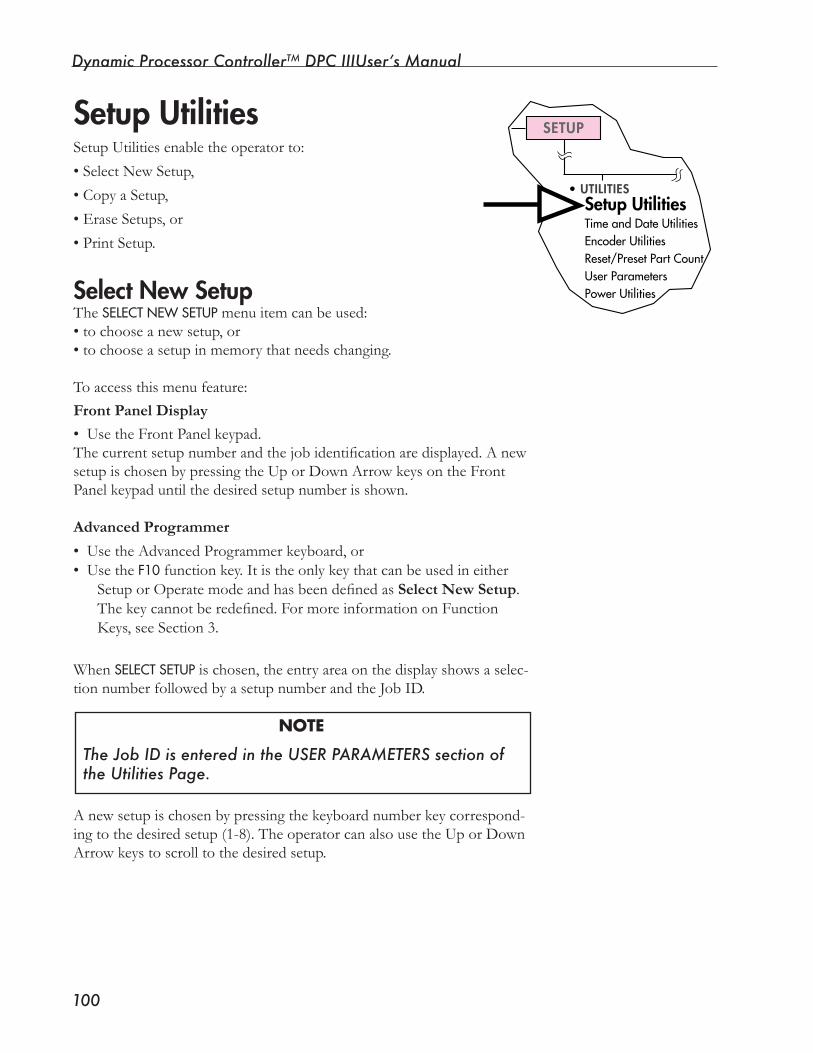
Dynamic Processor ControllerTM DPC IIIUser’s Manual
�00
SETUP
•UTILITIESSetup UtilitiesTimeandDateUtilitiesEncoderUtilitiesReset/PresetPartCountUserParametersPowerUtilities
Setup UtilitiesSetupUtilitiesenabletheoperatorto:
•SelectNewSetup,
• Copy a Setup,
• Erase Setups, or
• Print Setup.
Select New SetupThe SELECTNEWSETUPmenuitemcanbeused:•tochooseanewsetup,or• to choose a setup in memory that needs changing.
Toaccessthismenufeature:Front Panel Display
• Use the Front Panel keypad.Thecurrentsetupnumberandthejobidentificationaredisplayed.AnewsetupischosenbypressingtheUporDownArrowkeysontheFrontPanelkeypaduntilthedesiredsetupnumberisshown.
Advanced Programmer
• Use the Advanced Programmer keyboard, or• Use the F10 function key. It is the only key that can be used in either
SetuporOperatemodeandhasbeendefinedasSelect New Setup. Thekeycannotberedefined.FormoreinformationonFunctionKeys, see Section 3.
When SELECTSETUPischosen,theentryareaonthedisplayshowsaselec-tionnumberfollowedbyasetupnumberandtheJobID.
NOTE
The Job ID is entered in the USER PARAMETERS section of the Utilities Page.
Anewsetupischosenbypressingthekeyboardnumberkeycorrespond-ingtothedesiredsetup(1-8).TheoperatorcanalsousetheUporDownArrowkeystoscrolltothedesiredsetup.
Section 9 Setup Mode, Utilities Page
�0�
NOTE
With both the Front Panel and Advanced Programmer, the ENTER key selects the new setup, and the DELETE key cancels any selection made.
Copy a SetupUsing this selection data from one setup is copied into the current setup.
When COPYASETUPis selected, enter the setup number of the setup to be copied. When the ENTERkey is pressed to the DPC III asks for confirmationbydisplayinganOKTOOVERWRITE?message.
If YESischosen,thespecifiedsetupwillbecopiedintothecurrentsetup. Selecting NOor pressing the DELETEkey cancels the operation.
Erase Setups
When ERASESETUP is chosen, the operator can erase the current setup or erase all setups. Once setups have been removed from memory, they must be reentered to be restored. The menu choices are explained on the next page.
Setup Utilities, continued
Continued
It is a good idea to make a printed copy of all setups as a way of back-ing up what’s in the DPC III memory. Once the deletion process begins, it cannot be stopped.
CAUTION
Dynamic Processor ControllerTM DPC IIIUser’s Manual
�0�
Erase Current SetupErasing the current setup removes all setup information for the current setup.If thisitemisselected,theDPCIIIpromptstheoperatorwithOKTOERASESETUP?beforeproceedingwiththeoperation.Toerasethesetup, select YES. To cancel, select NOor press DELETE.
Erase All SetupsErasing all setups removes all setup parameters in all setups. If this item isselected,theDPCIIIpromptstheoperatorwiththemessage:OKTOERASEMEMORY?. If YESis selected, all setups are erased from memory. (This operation can take from 1 to 20 seconds.) To cancel the operation, choose NOor press DELETE.
Print SetupUse this menu item to print a setup selection to a printer or to a com-puterfile.If thisselectionischosen,theoperatormaychooseeitherTEXT or HEX.
Print Setup - TextThisselectionallowsprintingof asetuptoaprinter(forbackuppur-poses).
NOTE
Printing a setup in this mode can only be done when the OUTPUT DEVICE has been set to one of the four printer types (Epson FX-85, etc.) or to ASCII. Trying to print in any other way results in the appearance of a warning, W02:INVALIDOUTPUTDEVICE on the Front Panel display and on the status line of the Advanced Programmer display.
Figure9-3showsanexampleof asetupprintedbyaprinter.
Erase Setups, continued

Section 9 Setup Mode, Utilities Page
�0�
----------------------------------------------------------------------------------------------------------------- SETUP 2: LOWER LIM ITS UPPER LIMITS PROCESS LIMITS PROCESS SEQUENCE BAD SUSPECT BAD ------------------------- ------- ---------------- ------- ---------------- 1.250 1.450 2.4000 2.4500 NORMAL TRIGGER WELD BY TIME 1.200 275 HOLD BY TIME 1.000
TOTAL CYCLE TIME TOTAL STROKE
--------------------------------------PEAK POWER 395
--------------------------------------OUTPUT DEVICEOUTPUT MODEBAUD RATEPROTOCOLLF AFTER CRLIMIT INDICATORSTIME TAG
- IBM PRO XL- ALL- 9600- X0N/X0FF- YES- ENABLED- ENABLED
--------------------------------------JOB IDHORNBOOSTERFIXTUREPRESSURE 1PRESSURE 2TRIGGER FORCE
SECONDARY CONTROLS
USER PARAMETERSCOMMUNICATIONS
- Setup 2- --- 20.0- 35.0- 2.25
ADVANCED PROGRAMMER ENCODER UTILITIES--------------------------------------
--------------------------------------
--------------------------------------
--------------------------------------
BAUD RATESTATUS
- 9600- ENABLED
ENCODER UNITS - ENGLISH
I/O GRAPHING
OUTPUTSUP VALVE ON ABORTEND OF WELD/GND DETSTATUS OUTPUTSDEFINE J602-5 ASDEFINE J602-6 ASBUZZER STATUS
- ACTIVE HI- OFF- DISABLED- MAINTAINED- GOOD PART- READY- ON
LEFT AXISRIGHT AXISSTART ATSTOP ATTIME SCALEPOWER SCALEDISTANCE SCALE
- POWER- DISTANCE- WELD- END OF HOLD- 0.050 SEC- AUTO RANGE- AUTO RANGE
PART SAMPLING MISCELLANEOUS
LOT SIZESAMPLE SIZEEXCLUDESTORE
- 100- 5- NONE- NONE
POWER AVERAGEDATE FORMATINITIATE MODETRIGGER METHOD
- EIGHT- MM-DD-YY- AUTO- MAINTAINED
SEQUENCING
SEQUENCINGSEGMENT LENGTHRESET SEQUENCEDEFINE PART AS
- DISABLED- 0- BAD- CYCLE
---------------------------------------------------------------------------------------------------Time: 12:58:24 © 1989—2004 Dukane CorpDate: 10-20-99 v1.xxxx
-------------------------------------- --------------------------------------
--------------------------------------
DOWNSTROKE TIME DOWNSTROKE DIST
WELD TIME P1PEAK POWER
Figure9-3 Example of a Printed Setup
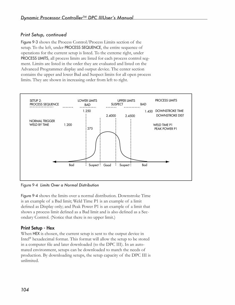
Dynamic Processor ControllerTM DPC IIIUser’s Manual
�0�
Figure9-3showstheProcessControl/ProcessLimitssectionof thesetup. To the left, underPROCESSSEQUENCE, the entire sequence of operations for the current setup is listed. To the extreme right, under PROCESSLIMITS, all process limits are listed for each process control seg-ment. Limits are listed in the order they are evaluated and listed on the Advanced Programmer display and output device. The center section containstheupperandlowerBadandSuspectlimitsforallopenprocesslimits.Theyareshowninincreasingorderfromlefttoright.
Figure9-4showsthelimitsoveranormaldistribution.DownstrokeTimeis an example of a Bad limit; Weld Time P1 is an example of a limit definedasDisplayonly;andPeakPowerP1isanexampleof alimitthatshowsaprocesslimitdefinedasaBadlimitandisalsodefinedasaSec-ondary Control. (Notice that there is no upper limit.)
Print Setup - HexWhen HEX is chosen, the current setup is sent to the output device in Intel®hexadecimalformat.Thisformatwillallowthesetuptobestoredinacomputerfileandlaterdownloaded(totheDPCIII).Inanauto-matedenvironment,setupscanbedownloadedtomatchtheneedsof production.Bydownloadingsetups,thesetupcapacityof theDPCIIIisunlimited.
SETUP2:PROCESSSEQUENCE
NORMALTRIGGERWELDBYTIME 1.200
1.250
275
2.4000 2.45001.450
LOWERLIMITS UPPERLIMITS PROCESSLIMITS
DOWNSTROKETIMEDOWNSTROKEDIST
WELDTIMEP1PEAKPOWERP1
Bad BadGoodSuspect Suspect
BAD BADSUSPECT
Figure9-4 Limits Over a Normal Distribution
Print Setup, continued
Section 9 Setup Mode, Utilities Page
�0�
SETUP
•UTILITIESSetupUtilitiesTime and Date UtilitiesEncoderUtilitiesReset/PresetPartCountUserParametersPowerUtilities
Time and Date UtilitiesThe DPC III has a real-time clock/calendar. With this fea-turetheoperatorcan:
• Set the time and date, and•Determinewhethertheclock/calendarisfunctioning
properly.Wheninproduction,theutilityallowsthepartdatatobetime-tagged.Inthiswayapartislinkedtoaspecifictimeanddate.
Set DateThecalendarportionof thereal-timeclock/calendarissetwiththismenuitem.DateformatisbasedonwhatischosenintheDATEFOR-MATmenuitemexplainedbelow.
Set TimeThe internal clock can be set using this menu item. Set the clock in 24-hourformat:Hours(HH),Minutes(MM),andSeconds(SS).
Check DateWiththismenuitemthecurrentdateisdisplayed.Thedisplayfieldisupdatedeachsecond,withthecurrentdate.
Check TimeWith this menu item, the current time of the real-time clock is displayed.Thisdisplayfieldisupdatedonceeachsecondwiththecur-rent time.
Date FormatWiththismenuitemtheoperatorchooseshowthedatewillbedis-playedusingoneof thefollowingformats:• MM–DD–YY (Month–Day–Year),• DD–MM–YY, or• YY–MM–DD.
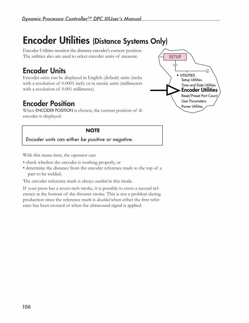
Dynamic Processor ControllerTM DPC IIIUser’s Manual
�0�
Encoder Utilities monitor the distance encoder’s current position. The utilities also are used to select encoder units of measure.
Encoder UnitsEncoder units can be displayed in English (default) units (inches witharesolutionof 0.0001inch)orinmetricunits(millimeterswitharesolutionof 0.001millimeter).
Encoder PositionWhen ENCODERPOSITION is chosen, the current position of the encoder is displayed.
NOTE
Encoder units can either be positive or negative.
Withthismenuitem,theoperatorcan:•checkwhethertheencoderisworkingproperly,or• determine the distance from the encoder reference mark to the top of a parttobewelded.
Theencoderreferencemarkisalwaysenabled in this mode. If your press has a seven-inch stroke, it is possible to cross a second ref-erence at the bottom of the thruster stroke. This is not a problem during production since the reference mark is disabledwheneitherthefirstrefer-encehasbeencrossedorwhentheultrasoundsignalisapplied.
Encoder Utilities (Distance Systems Only)
SETUP
•UTILITIESSetupUtilitiesTimeandDateUtilitiesEncoder UtilitiesReset/PresetPartCountUserParametersPowerUtilities

Section 9 Setup Mode, Utilities Page
�0�
SETUP
•UTILITIESSetupUtilitiesTimeandDateUtilitiesEncoderUtilitiesReset/Preset Part CountUserParametersPowerUtilities
SETUP
•UTILITIESSetupUtilitiesTimeandDateUtilitiesEncoderUtilitiesReset/PresetPartCountUser ParametersPowerUtilities
Reset/Preset Part CountWith this utility the operator can modify the part count.
Reset Part CountSelecting this menu item sets the part count to zero (0). This also sets the Sample counter to zero (0).
Preset Part CountThe operator enters a number for the part count (maximum of 999,999). Preset Part Count has no effect on the Sample counter.
User ParametersThis menu item gives the operator a place to enter notes that identify partsandconditionsassociatedwithaparticularsetup.Informationaboutthesesevenparameterscanbeentered:
• Job Number,
• Horn,
• Booster,
• Fixture,
• Pressure 1,
• Pressure 2, and
• Trigger Force.
Job NumberThisisa10-characterfieldinwhichtheoperatorcanenteranameornumbertoidentifythejoborpartthatisassociatedwiththecurrentsetup.Thejobidentificationappearsatthetopof eachAdvancedPro-grammer Setup page (Process Control Page, Process Limits Page, etc.) next to the setup number.
Whenchoosinganewsetup,thejobidentificationisdisplayedwiththesetup number in the Advanced Programmer entry area and on the Front Panel display.
Continued
Dynamic Processor ControllerTM DPC IIIUser’s Manual
�0�
HornThis10-characterfieldallowstheoperatortoenterthehornnumber or description.
BoosterThe10-characterBoosterfieldcanbeusedtoenteraboosternumberoritsgainratio(2:1forinstance).
FixtureThis10-characterfieldletstheoperatorenteranumberorde-scriptionof thefixture.
Pressure 1EntertheairpressuresettingforPressure1whichisusedforDownstrokeandsinglepressurewelding.
Pressure 2Enter the air pressure setting for Pressure 2. Pressure 2 is used duringthePressure2portionof adualpressureweldingappli-cationandduringtheHoldportionof theweldcycle.
Trigger ForceThe TRIGGERFORCEsettingprovidesanentryfieldtorecordthetrigger force. Enter the numeric setting that is on the thruster’s triggerswitch.
User Parameters, contin-
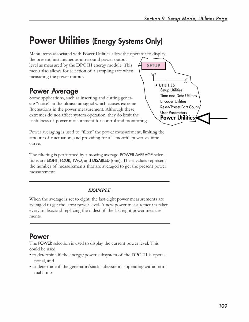
Section 9 Setup Mode, Utilities Page
�0�
SETUP
•UTILITIESSetupUtilitiesTimeandDateUtilitiesEncoderUtilitiesReset/PresetPartCountUserParametersPower Utilities
MenuitemsassociatedwithPowerUtilitiesallowtheoperatortodisplaythepresent,instantaneousultrasoundpoweroutputlevel as measured by the DPC III energy module. This menualsoallowsforselectionof asamplingratewhenmeasuringthepoweroutput.
Power AverageSome applications, such as inserting and cutting gener-ate“noise”intheultrasonicsignalwhichcausesextremefluctuationsinthepowermeasurement.Althoughtheseextremes do not affect system operation, they do limit the usefulnessof powermeasurementforcontrolandmonitoring.
Poweraveragingisusedto“filter”thepowermeasurement,limitingtheamountof fluctuation,andprovidingfora“smooth”powervs.timecurve.
Thefilteringisperformedbyamovingaverage. POWERAVERAGE selec-tions are EIGHT, FOUR, TWO, and DISABLED(one). These values represent thenumberof measurementsthatareaveragedtogetthepresentpowermeasurement.
EXAMPLE
Whentheaverageissettoeight,thelasteightpowermeasurementsareaveragedtogetthelatestpowerlevel.Anewpowermeasurementistakeneverymillisecondreplacingtheoldestof thelasteightpowermeasure-ments.
PowerThe POWERselectionisusedtodisplaythecurrentpowerlevel.Thiscouldbeused:•todetermineif theenergy/powersubsystemof theDPCIIIisopera-
tional, and •todetermineif thegenerator/stacksubsystemisoperatingwithinnor-
mal limits.
Power Utilities (Energy Systems Only)

Dynamic Processor ControllerTM DPC IIIUser’s Manual
��0
This page intentionally left blank

SECTION 10
Setup Mode, Sequencing Page• ThissectiondescribeshowtheDPCIIIcanbeusedforjobsthatrequiremultipleweldsinasingle setup.
Dukane Corporation

Dynamic Processor ControllerTM DPC III Plus User’s Manual
This page intentionally left blank
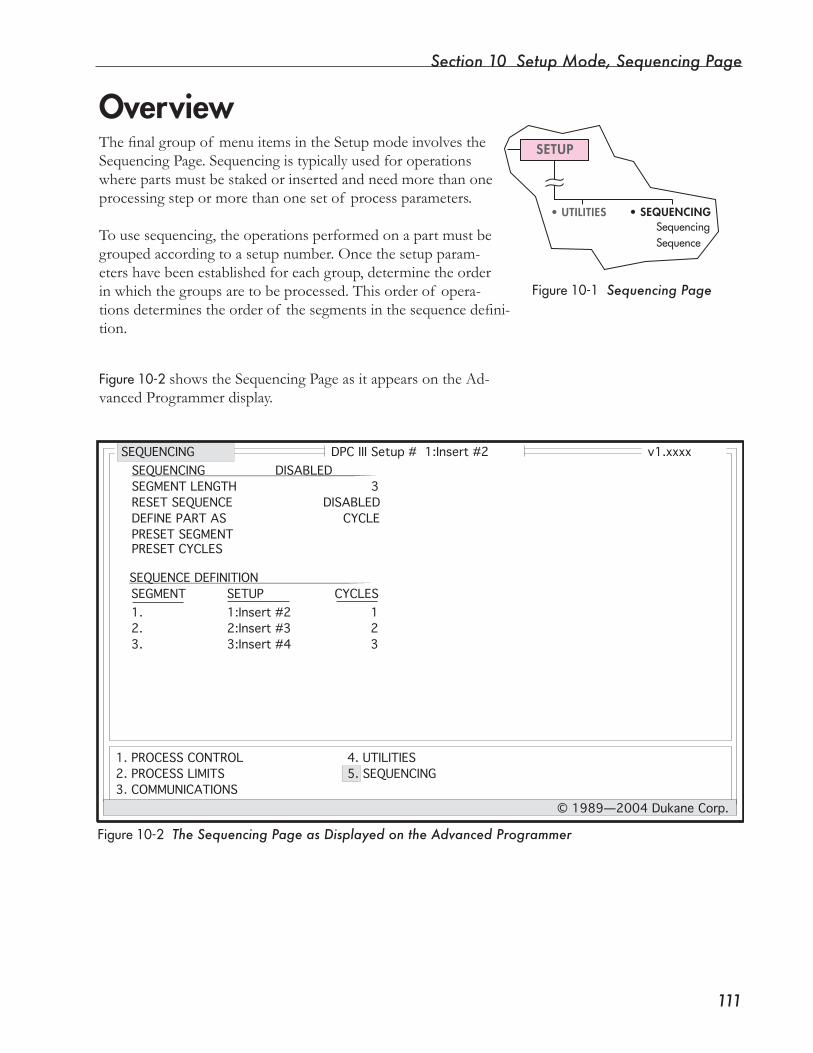
Section 10 Setup Mode, Sequencing Page
���
SETUP
• UTILITIES • SEQUENCINGSequencingSequence
Overview
Figure10-1 Sequencing Page
Figure10-2 The Sequencing Page as Displayed on the Advanced Programmer
DPC III Setup # 1:Insert #2 v1.xxxx
1. PROCESS CONTROL2. PROCESS LIMITS3. COMMUNICATIONS
4. UTILITIES5. SEQUENCING
© 1989—2004 Dukane Corp.
SEQUENCING
SEGMENT LENGTH 3RESET SEQUENCE DISABLEDDEFINE PART AS CYCLEPRESET SEGMENTPRESET CYCLES
SEQUENCING DISABLED
SEQUENCE DEFINITIONSEGMENT SETUP CYCLES1. 1:Insert #2 12. 2:Insert #3 23. 3:Insert #4 3
Thefinalgroupof menuitemsintheSetupmodeinvolvestheSequencing Page. Sequencing is typically used for operations wherepartsmustbestakedorinsertedandneedmorethanoneprocessing step or more than one set of process parameters.
To use sequencing, the operations performed on a part must be grouped according to a setup number. Once the setup param-eters have been established for each group, determine the order inwhichthegroupsaretobeprocessed.Thisorderof opera-tionsdeterminestheorderof thesegmentsinthesequencedefini-tion.
Figure10-2showstheSequencingPageasitappearsontheAd-vanced Programmer display.

Dynamic Processor ControllerTM DPC IIIUser’s Manual
���
Figure10-3givesagraphicrepresentationof asequence.Thefigureshowsthatasequenceisapro-cess that has from 1 to 8 seg-ments and that each of those segments can have from 0 to 255 cycles.
What is a Sequence?
Figure10-3 What is a Sequence?
Segments:
From 1 to 8
2
1
3
4
5
8
Cycles per Segment:
From 0 to 255
01
23
45
67
89
255
Sequence
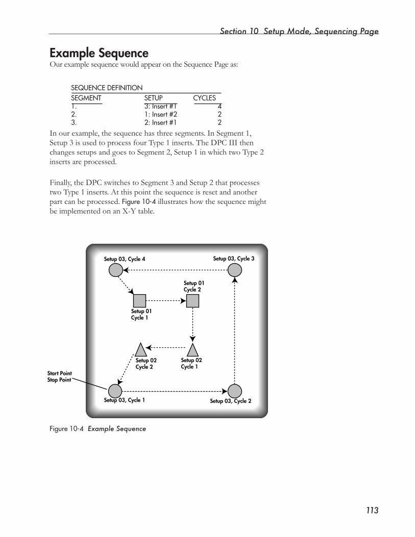
Section 10 Setup Mode, Sequencing Page
���
Example SequenceOurexamplesequencewouldappearontheSequencePageas:
In our example, the sequence has three segments. In Segment 1, Setup 3 is used to process four Type 1 inserts. The DPC III then changessetupsandgoestoSegment2,Setup1inwhichtwoType2inserts are processed.
Finally,theDPCswitchestoSegment3andSetup2thatprocessestwoType1inserts.Atthispointthesequenceisresetandanotherpart can be processed. Figure10-4illustrateshowthesequencemightbe implemented on an X-Y table.
SEQUENCEDEFINITIONSEGMENT SETUP CYCLES1. 3:Insert#1 42. 1:Insert#2 23. 2:Insert#1 2
Figure10-4 Example Sequence
Start PointStop Point
Setup 03, Cycle 1 Setup 03, Cycle 2
Setup 02Cycle 1
Setup 01Cycle 2
Setup 01Cycle 1
Setup 02Cycle 2
Setup 03, Cycle 3Setup 03, Cycle 4

Dynamic Processor ControllerTM DPC IIIUser’s Manual
���
SETUP
• UTILITIES • SEQUENCINGSequencingSequence
SequencingAfter SEQUENCINGis chosen, the operator selects fromalistof three“states”:Disabled,Enabled,orRemote.
DisabledSelect DISABLEDto turn off the sequencing feature.
EnabledWhen ENABLEDisselected,asequencecanbespecified.Agroupof fivesequencingparametersispresented:
• Segment Length,• Reset Sequence,•DefinePartAs,• Preset Segment, and• Preset Cycles.
Segment LengthSetthenumberof segmentsinthesequencebychoosinganumber:1through 8.
NOTE
If the segment length is changed with the Advanced Pro-grammer, the Sequence Definition menu item will be changed respectively.
Reset SequenceThismenuitemallowsthesequencetoresetautomaticallywhenaselect-edeventoccurs.Theseeventsare:BAD – Bad part detected.SUSPECT – Suspect part detected.ABORT – System abort occurs.DISABLED is selected to prevent an automatic sequence reset.
NOTE
A sequence can be reset manually from the Operate Page using the Advanced Programmer keyboard or the Front Panel keypad.
Section 10 Setup Mode, Sequencing Page
���
Define Part AsThismenuitemcontrolshowthesystemtreatsthepartcounter.
Cycle
The part counter is incremented every time the system cycles. Use this settingwhentheweldingprocessiscompletedinasinglecycle.
Sequence
Thepartcounterincrementsaftereverysequence.Usethissettingwhenweldingapartneedsmorethanonetypeof setup.
Preset SegmentTheoperatorcanprogramthesequencetostartwithacertainsegment(segment pointer) by using PRESETSEGMENT.Thisallowsresettingorpresettingasequenceincaseswhereaprocessproblemrequiresthatanoperation or group of operations needs repeating.
Preset CyclesTheoperatorcanprogramthesequencetostartwithaspecificcycle(cycle pointer) by using PRESETCYCLES. Thisallowstheresettingorpresettingof asequenceincaseswhereaprocess problem requires that an operation or group of operations be repeated.
NOTE
As with any entry field, Preset Segment can be defined as a function key.
Sequencing Enabled, continued
A single part number can be associated with a mul-tiple-operation assembly. All data generated for an entire assembly will have the same part number.
NOTE
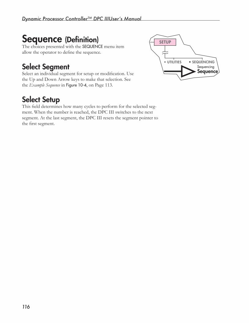
Dynamic Processor ControllerTM DPC IIIUser’s Manual
���
SETUP
• UTILITIES • SEQUENCINGSequencingSequence
Sequence (Definition)ThechoicespresentedwiththeSEQUENCEmenu item allowtheoperatortodefinethesequence.
Select SegmentSelectanindividualsegmentforsetupormodification.Use theUpandDownArrowkeystomakethatselection.See the Example Sequence in Figure10-4, on Page 113.
Select SetupThisfielddetermineshowmanycyclestoperformfortheselectedseg-ment.Whenthenumberisreached,theDPCIIIswitchestothenextsegment. At the last segment, the DPC III resets the segment pointer to thefirstsegment.
Section 10 Setup Mode, Sequencing Page
���
Functionkeysaredefinedintermsof andavailableforaparticularprocesssetup.Thatisimportanttorememberwhenplayingbackafunctionkeyfromthe Operate Page.
NOTE
The current Operate setup appears on the Front Panel display.
DuringSequencingorRemoteSetupSwitching,theDPCIIIchangestheOp-erate setups. Take care to make sure that the function key set desired matches the set for the current Operate setup.
Function Keys and Sequencing

Dynamic Processor ControllerTM DPC IIIUser’s Manual
���
This page intentionally left blank
SECTION 11
Operate Mode, Operate Page• Thissectiondescribeswaystomonitorthe
process functions.
Dukane Corporation

Dynamic Processor ControllerTM DPC III Plus User’s Manual
This page intentionally left blank
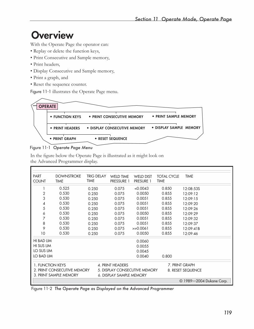
Section �� Operate Mode, Operate Page
���
Overview
Figure11-2 The Operate Page as Displayed on the Advanced Programmer
WiththeOperatePagetheoperatorcan:• Replay or delete the function keys,• Print Consecutive and Sample memory,• Print headers,• Display Consecutive and Sample memory,• Print a graph, and • Reset the sequence counter.Figure11-1 illustrates the Operate Page menu.
InthefigurebelowtheOperatePageisillustratedasitmightlookonthe Advanced Programmer display.
Figure11-1 Operate Page Menu
1. FUNCTION KEYS2. PRINT CONSECUTIVE MEMORY3. PRINT SAMPLE MEMORY
4. PRINT HEADERS5. DISPLAY CONSECUTIVE MEMORY
© 1989—2004 Dukane Corp.
PART DOWNSTROKECOUNT TIME
6. DISPLAY SAMPLE MEMORY
7. PRINT GRAPH 8. RESET SEQUENCE
HI BAD LIMHI SUS LIMLO SUS LIMLO BAD LIM
123456789
10
0.5250.5300.5300.5300.5300.5300.5300.5300.5300.530
TRIG DELAYTIME
WELD TIMEPRESSURE 1
WELD DISTPRESURE 1
TOTAL CYCLETIME
TIME
0.2500.2500.2500.2500.2500.2500.2500.2500.2500.250
0.0750.0750.0750.0750.0750.0750.0750.0750.0750.075
<0.00430.00500.00510.00510.00510.00500.00510.0051
>>0.00610.0050
0.8500.8550.8550.8550.8550.8550.8550.8550.8550.855
12:08:53S12:09:1212:09:1512:09:2012:09:2612:09:2912:09:3212:09:3712:09:41B12:09:46
0.00600.00550.00450.0040 0.800
OPERATE
• PRINT SAMPLE MEMORY• FUNCTION KEYS • PRINT CONSECUTIVE MEMORY
• PRINT HEADERS • DISPLAY CONSECUTIVE MEMORY • DISPLAY SAMPLE MEMORY
• PRINT GRAPH • RESET SEQUENCE
Dynamic Processor ControllerTM DPC IIIUser’s Manual
��0
Select the Operate ModeTurnthekeyswitchtotheOPERATEposition.Aweldcyclecanonlybestartedwiththeswitchinthisposition.Thekeycanberemovedwhenitisin the OPERATEposition.
Reviewing Process CharacteristicsAllprocesscharacteristicsfromtheweldcyclejustcompletedcanbere-viewedusingtheLeftandRightArrowkeysontheFrontPanelkeypad.
Parts processed previously cannot be displayed, although they can be downloadedtoaprinterorcomputerusingtherearpanelJ3serialportconnector.
Accessing Operate FunctionsPresstheUporDownArrowkeysontheFrontPanelkeypadtoscrollthrough the menu items.
Operate Page with Front Panel
To prevent access to the SETUP mode, and when the key-switch has been turned to OPERATE, remove the key.
NOTE

Section �� Operate Mode, Operate Page
���
Select the Operate ModePresseitherthePageUporPageDownkeyonthekeyboard.
NOTE
If there are more than �� process characteristics active for the current process, the Operate Page will display on two screens. The first screen will provide information for as many as 11 characteristics. The second screen will have information for the remaining characteristics.
NOTE
Switching the Front Panel keyswitch from SETUP to OPERATE changes the Advanced Programmer mode accordingly.
Reviewing Process CharacteristicsThe Advanced Programmer can display more information at a glance thantheFrontPaneldisplay(withitsone-linedisplay).Inaddition,whentheDisplayConsecutive/SampleMemorycommandsareused,parthistorycanbereviewedaswell.
Accessing Operate FunctionsOperatefunctionscanbeselectedusingtheUpandDownArrowkeyson the Advanced Programmer keyboard. Operate functions can also be chosen by pressing the number key corresponding to the menu item linked to each function.
EXAMPLETo print headers, press the “4” key on the Advanced Programmer keyboard.
Operate Page with Advanced Programmer
Continued

Dynamic Processor ControllerTM DPC IIIUser’s Manual
���
Operate FunctionsFunction KeysFunctionkeyscanbereplayedinseveralways:•withtheAdvancedProgrammerfunctionkeys(F1throughF10),or•withtheUp/DownArrowkeysof theFrontPanelorAdvancedPro-
grammer.Function keys can be used to change process parameters during the “trial anderror”processof setup,andtheycanallowtheoperatorlimitedac-cess in making setup changes to the system.
NOTE
Each setup has its own set of nine function keys. If multiple setups are to be used, define the keys for each setup.
Remember: F10 is permanently defined as, SelectNewSetup.
For more information about Function Keys, see Section 3, Controls, Pages 31-32.
Print Part MemoryEither Consecutive or Sample part memory can be sent to an output device giving a hard copy record of part memories.
When either PRINTCONSECUTIVEMEMORY or PRINTSAMPLEMEMORY is accessed,themessage:PARTSTODOWNLOAD is displayed. The number of available parts is displayed in parentheses (xx) to the left of the entry field.Enterthenumberof partstobedownloaded.To cancel the print operation, press the DELETEkey.
Print Headers“Headers”referstothewordsthatappearatthetopsof columnsontheAdvanced Programmer display. They identify the columns of process characteristicsappearingbelowthem.Havingtheheadersprintedhelpstoidentifywhathasbeenrecorded.
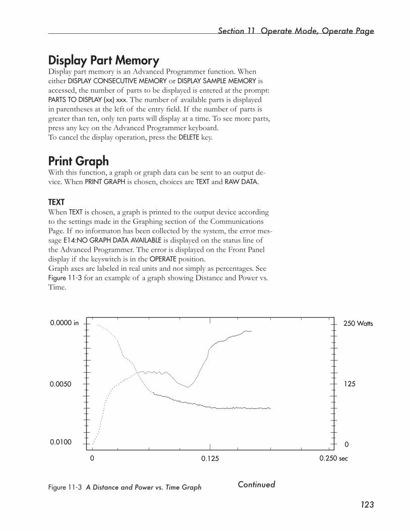
Section �� Operate Mode, Operate Page
���
Display Part MemoryDisplay part memory is an Advanced Programmer function. When either DISPLAYCONSECUTIVEMEMORY or DISPLAYSAMPLEMEMORY is accessed,thenumberof partstobedisplayedisenteredattheprompt:PARTSTODISPLAY(xx)xxx. The number of available parts is displayed inparenthesesattheleftof theentryfield.If thenumberof partsisgreaterthanten,onlytenpartswilldisplayatatime.Toseemoreparts,press any key on the Advanced Programmer keyboard. To cancel the display operation, press the DELETEkey.
Print GraphWith this function, a graph or graph data can be sent to an output de-vice. When PRINTGRAPH is chosen, choices are TEXT and RAWDATA.
TEXTWhen TEXT is chosen, a graph is printed to the output device according to the settings made in the Graphing section of the Communications Page. If no informaton has been collected by the system, the error mes-sage E14:NOGRAPHDATAAVAILABLE is displayed on the status line of the Advanced Programmer. The error is displayed on the Front Panel displayif thekeyswitchisintheOPERATEposition.Graph axes are labeled in real units and not simply as percentages. See Figure11-3foranexampleof agraphshowingDistanceandPowervs.Time.
ContinuedFigure11-3 A Distance and Power vs. Time Graph
250 Watts
125
0
0.250 sec0.1250
0.0100
0.0050
0.0000 in
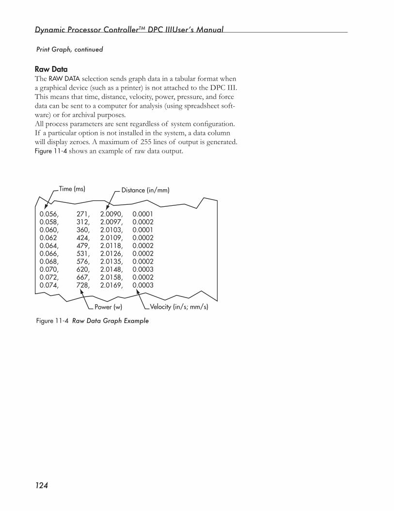
Dynamic Processor ControllerTM DPC IIIUser’s Manual
���
Print Graph, continued
Raw DataThe RAWDATAselectionsendsgraphdatainatabularformatwhena graphical device (such as a printer) is not attached to the DPC III. Thismeansthattime,distance,velocity,power,pressure,andforcedata can be sent to a computer for analysis (using spreadsheet soft-ware)orforarchivalpurposes.Allprocessparametersaresentregardlessof systemconfiguration.If a particular option is not installed in the system, a data column willdisplayzeroes.Amaximumof 255linesof outputisgenerated.Figure11-4showsanexampleof rawdataoutput.
0.056,0.058,0.060,0.0620.064,0.066,0.068,0.070,0.072,0.074,
271,312,360,424,479,531,576,620,667,728,
2.0090,2.0097,2.0103,2.0109,2.0118,2.0126,2.0135,2.0148,2.0158,2.0169,
0.00010.00020.00010.00020.00020.00020.00020.00030.00020.0003
Time (ms) Distance (in/mm)
Velocity (in/s; mm/s)Power (w)
Figure11-4Raw Data Graph Example
Section �� Operate Mode, Operate Page
���
Reset SequenceThismenuselectionallowstheoperatortomanuallyresetasequenceincase a system error or Bad part limit is exceeded. Before the sequence is reset,theoperatorispromptedbythesystemwhethertheresetshouldbe carried out. The message OKTORESETSEQUENCE is displayed. Then a YES/NO choice is made.Choosing NOcancels the operation to reset the sequence.Choosing YESresets the system to the beginning of a sequence.
NOTE
Presetting a sequence can be done by defining one func-tion key as PRESETSEGMENT and another function key as PRESETCYCLES.

Dynamic Processor ControllerTM DPC IIIUser’s Manual
���
This page intentionally left blank
SECTION 12
Specifications• This section has a regulatory agency compliance
statement, dimensions, operating requirements, and an explanation of the model number..
Dukane Corporation

Dynamic Processor ControllerTM DPC III Plus User’s Manual
This page intentionally left blank
Section 12 Specifications
���
Regulatory Agency Compliance
FCCThe equipment complies with the following Fed-eral Communications Commission regulations.• The limits for FCC measurement procedure
MP-5, “Methods of Measurement of Radio Noise Emissions from ISM Equipment”, pur-suant to FCC Title 47 Part 18 for Ultrasonic Equipment.
CE MarkingThis mark on your equipment certifies that it meets the requirements of the EU (European Union) concerning interference causing equip-ment regulations. CE stands for Conformité Eu-ropeéne (European Conformity). The equipment complies with the following CE requirements.• The EMC Directive 2004/108/EC for Heavy
Industrial — EN 61000-6-4: 2001
EN 55011: 2003 EN 61000-6-2: 2001 EN61000–4–2
EN61000–4–3 EN61000–4–4 EN61000–4–5 EN61000–4–6 EN61000–4–8 EN61000–4–11
• The Low Voltage Directive 2006/95/EC.
• The Machinery Directive 2006/42/EC. EN 60204: 2006
Safety of Machinery - Electrical Equipment of Machines Part 1: Gen-eral Requirements.
CAUTION
DO NOT make any modifications to the DPC or associated ca-bles as the changes may result in violating one or more regula-tions under which this equipment is manu-factured.
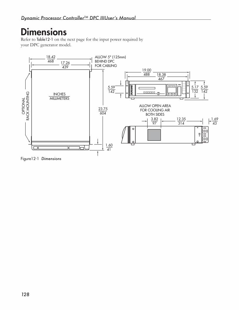
Dynamic Processor ControllerTM DPC IIIUser’s Manual
���
Dimensions Refer to Table12-1onthenextpagefortheinputpowerrequiredbyyour DPC generator model.
Figure12-1Dimensions
18.42468 17.26
439
INCHESMILLIMETERS
23.75604
1.6041
3.8297
12.35314
1.6943
ALLOW 5" (125mm)BEHIND DPC FOR CABLING
OPT
ION
AL
RAC
K M
OU
NTI
NG
ALLOW OPEN AREAFOR COOLING AIR
BOTH SIDES
5.17132
5.59142
18.38467
19.00488
5.59142
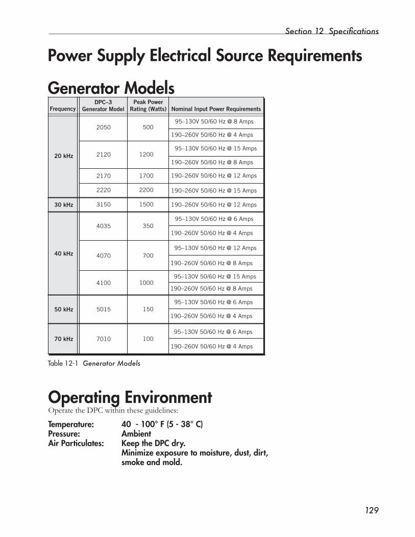
Section 12 Specifications
���
Generator Models
Table12-1 Generator Models
Power Supply Electrical Source Requirements
Operating EnvironmentOperatetheDPCwithintheseguidelines:
Temperature: 40 - 100° F (5 - 38° C)Pressure: AmbientAir Particulates: Keep the DPC dry. Minimize exposure to moisture, dust, dirt, smoke and mold.
2050
2120
2170
2220
3150
4035
4070
4100
5015
701070 kHz
50 kHz
40 kHz
30 kHz
20 kHz
FrequencyDPC–3
Generator ModelPeak Power
Rating (Watts) Nominal Input Power Requirements
500
1200
1700
2200
1500
350
700
1000
150
100
95–130V 50/60 Hz @ 8 Amps
95–130V 50/60 Hz @ 15 Amps
95–130V 50/60 Hz @ 6 Amps
95–130V 50/60 Hz @ 12 Amps
95–130V 50/60 Hz @ 15 Amps
95–130V 50/60 Hz @ 6 Amps
95–130V 50/60 Hz @ 6 Amps
190–260V 50/60 Hz @ 4 Amps
190–260V 50/60 Hz @ 4 Amps
190–260V 50/60 Hz @ 8 Amps
190–260V 50/60 Hz @ 4 Amps
190–260V 50/60 Hz @ 4 Amps
190–260V 50/60 Hz @ 8 Amps
190–260V 50/60 Hz @ 8 Amps
190–260V 50/60 Hz @ 12 Amps
190–260V 50/60 Hz @ 12 Amps
190–260V 50/60 Hz @ 15 Amps
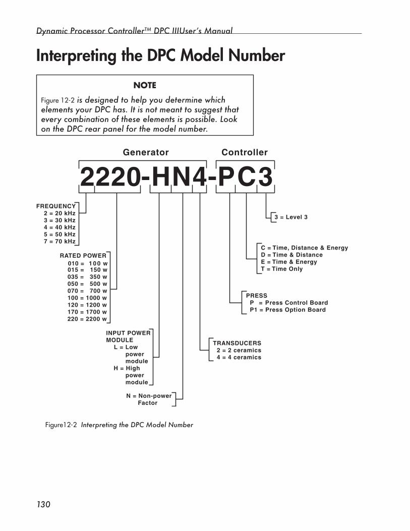
Dynamic Processor ControllerTM DPC IIIUser’s Manual
��0
Interpreting the DPC Model Number
NOTE
Figure12-2 is designed to help you determine which elements your DPC has. It is not meant to suggest that every combination of these elements is possible. Look on the DPC rear panel for the model number.
Figure12-2 Interpreting the DPC Model Number
2220-HN4-PC3 Generator Controller
FREQUENCY 2 = 20 kHz 3 = 30 kHz 4 = 40 kHz 5 = 50 kHz 7 = 70 kHz
RATED POWER
015 = 150 w 035 = 350 w 050 = 500 w 070 = 700 w 100 = 1000 w 120 = 1200 w 170 = 1700 w
INPUT POWERMODULE L = Low power module H = High power module
N = Non-power Factor
TRANSDUCERS 2 = 2 ceramics 4 = 4 ceramics
PRESS P = Press Control Board P1 = Press Option Board
010 = 1 0 0 w
C = Time, Distance & EnergyD = Time & DistanceE = Time & EnergyT = Time Only
3 = Level 3
220 = 2200 w

SECTION 13
Care and Troubleshooting• This section has information about care of the
DPC III controller, and it describes error and warningmessages.
Dukane Corporation

Dynamic Processor ControllerTM DPC III Plus User’s Manual
This page intentionally left blank
Section 13 Care and Troubleshooting
���
CareEnvironmentProlongthelifeof yourDPCIIIintheseways:
• HandletheDPCwithcare.Itisasensitiveelectronicdevice,andshouldbetreatedaccordingly.Itisnotdesignedtowithstandhighimpactblowsof anykind.
• Do not expose the DPC to moisture. Keep the unit dry.
• Minimize the DPC’s exposure to, dust, dirt, smoke, and the ex-tremesof temperature.Allarefactorswhichcanshortencompo-nent life.
• Keepfingersclean.Becausetheywillbetouchingthekeypad,andcancarrydirt,grease,etc.,fingersshouldbeascleanaspossible.
Front PanelThe operator controls on the Front Panel (keypad, generator control keysandACpowerswitch)respondtoagentlebutfirmtouch.Neveruse a sharply pointed object to touch any of these controls.
CAUTION
PLEASE, do not use any sharply point-ed object to touch any part of the DPC front panel!
CleaningWhen cleaning the DPC, put a small amount of computer cleaner on asoftcloth,andgentlywipetheclothandcleaneroverthesurfacetobecleaned.Donotapply(sprayorotherwise)anycleanerdirectlytothe DPC.
NOTE
Handle your Advanced Programmer display and keyboard with the same care outlined here for the DPC.

Dynamic Processor ControllerTM DPC IIIUser’s Manual
���
Replaceable PartsThe DPC III is a self-contained device and has no parts that are replaceable by the end user.
When parts need replacing, contact Dukane Corporation.See Section 14 for contact information.

Section 13 Care and Troubleshooting
���
Problem PossibleSolutionFront Panel display image disappears.Panel goes dark.
1. Check to see that the DPC’s green, LED powerlightison.
2. If the light is not on, tighten all cable connec-tions. Then, make certain the DPC rear panel ACbreakerswitchandtheFrontPanelpowerswitcharebothintheON position.
NOTE
Contact Dukane Corporation for servicing. (See Section 14.) The DPC and Advanced Programmer are serviceable only by Dukane personnel. Unauthorized attempts to service either unit will void any warranty.
Troubleshooting
Theultrasoundsignalwillshutdownduringanoverload condition. If overloading continues, analysisof applicationandhardwaremaybeneeded.Contact Dukane Corporation. See Section 14 for contact information.
SystemStatusDisplayshowsOVERLOAD condition.
Unitpower-upsequencestops,andSystemStatusDisplay INPUTTESTisflashing.
Theself testroutineforinputpowercompat-ibilitywiththeDPChasfoundaproblem.Thepower-upsequencewillnotcontinueuntiltheproblem is resolved. Recheck line voltage and DPC system requirements.Anotherpossibility:afaultmayhaveoccurredonthe DPC’s input module circuit.
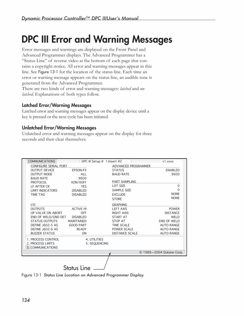
Dynamic Processor ControllerTM DPC IIIUser’s Manual
���
ErrormessagesandwarningsaredisplayedontheFrontPanelandAdvanced Programmer displays. The Advanced Programmer has a “Status Line” of reverse video at the bottom of each page that con-tainsacopyrightnotice.Allerrorandwarningmessagesappearinthisline. See Figure13-1 for the location of the status line. Each time an errororwarningmessageappearsonthestatusline,anaudibletoneisgenerated from the Advanced Programmer.Therearetwokindsof errorandwarningmessages:latched and un-latched.Explanationsof bothtypesfollow.
Latched Error/Warning MessagesLatchederrorandwarningmessagesappearonthedisplaydeviceuntilakey is pressed or the next cycle has been initiated.
Unlatched Error/Warning MessagesUnlatchederrorandwarningmessagesappearonthedisplayforthreeseconds and then clear themselves.
DPC III Error and Warning Messages
Figure13-1 Status Line Location on Advanced Programmer Display
DPC III Setup # 1:Insert #2 v1.xxxx
1. PROCESS CONTROL2. PROCESS LIMITS3. COMMUNICATIONS
4. UTILITIES5. SEQUENCING
© 1989—2004 Dukane Corp.
COMMUNICATIONS
OUTPUT DEVICEOUTPUT MODEBAUD RATEPROTOCOLLF AFTER CRLIMIT INDICATORSTIME TAG
OUTPUTSUP VALVE ON ABORTEND OF WELD/GND DETSTATUS OUTPUTSDEFINE J602-5 ASDEFINE J602-6 ASBUZZER STATUS
STATUS BAUD RATE
LOT SIZESAMPLE SIZEEXCLUDESTORE
LEFT AXISRIGHT AXISSTART ATSTOP ATTIME SCALEPOWER SCALEDISTANCE SCALE
EPSON-FXALL
9600XON/XOFF
YESDISABLEDDISABLED
ACTIVE HIOFF
DISABLEDMAINTAINEDGOOD PART
READYON
ENABLED9600
00
NONENONE
POWERDISTANCE
WELDEND OF WELDAUTO RANGEAUTO RANGEAUTO RANGE
CONFIGURE SERIAL PORT
I/O
ADVANCED PROGRAMMER
PART SAMPLING
GRAPHING
Status Line
Section 13 Care and Troubleshooting
���
Error messages appear on the Front Panel display and on the Ad-vanced Programmer display status line. Error messages remain on the displays until cleared by removing the condition that caused them (e.g., a system abort) or by pressing an Advanced Programmer or Front Panel key. Errors 04 – 09, I/O Active at Cycle Start, appear for three seconds and then disappear for three seconds. Each time the error message appears, it is accompanied by an audible tone from the Advanced Programmer.
E00:EEPROMWRITEVERIFYERROR(This is a latched error.)
TheEEPROMWriteVerifyerroroccurswhenanattempttowriteto the EEPROM (Electrically Erasable Programmable Read-Only Memory) fails. The EEPROM contains the setup information for the DPC III. If updates to the setup memory fail, unintended operation of the DPC may result.
If the E00:EEPROM WRITE VERIFY ER-ROR appears on the Front Panel dis-play or the Advanced Programmer status line, contact the Dukane Ultra-
sonics Service Department immediately.
E01:CYCLEABORTED(This is a latched error.)
The Cycle Aborted error message apears on the Advanced Program-merstatuslinewhiletheDPCAbortinputisasserted.OntheFrontPanel,theCycleAbortederrorisdisplayedonlywhenthekeyswitchis in the OPERATEposition.Thisallowsthesystemtobeprogrammedin the SETUPmode even though the system is aborted and cannot be placed in cycle. Note that the 24VDC to the press head is removed whentheAbortswitchsuppliedwiththesafetyswitchesispressed.With an automated system, the UPVALVEONABORT menu item on the Communications Page may be set to ONduring an abort. This prevents heavy horns from pulling the press head into the path of movingtablesandfixtures.The24VDCsupplytothepressshouldnotbeswitchedthroughtheAbortswitchinthiscase.RefertoAp-pendix A – I/O for details on controlling the 24VDC to the press.
Error Messages
CAUTION
Continued
Dynamic Processor ControllerTM DPC IIIUser’s Manual
���
Cycle Aborted, continued
E02:ENCODERERROR(Distancesystemsonly)Theencodersignalisalow-levelquadratureoutputthatdetectschanging position and direction of travel. If one or more of the quadratureinputsisweakorlost,anencodererrorsignalissenttotheDPCIII.EncodererrorhasnoeffectontheDPCcycle.Itwillnotterminateoraltertheflowof theprocess.Itmayhaveaneffecton the distance measurements and therefore should be addressed as quicklyaspossible.Encodererrorsmaybearesultof thefollowingsituations:
• Incorrect encoder alignmentThegapbetweentheencoderreadheadandtheencoderscaleshouldbesetat0.039inch(1mm).Thismeasurementshouldbetakenwithfeelergaugeswhenthereadheadisatboththetopandthebottomof theencoderscale.Theallowabletoleranceasspecifiedbythemanufactureris±0.005inchyieldinganallowablerangeof 0.034inchto 0.044 inch.
• Damaged encoder cableBecausetheencodersignalsareof alowlevel,damagetothecable,such as a cut or splice, can cause interruption or corruption of the signals from the encoder. If the cable is damaged, contact the Du-kane Ultrasonics Service Department for a replacement.
E03:SERIALPORTTIME-OUTERRORASerialPortTime-outerroroccurswhentheDPCIIIcannotcom-municatetotheoutputdevice.Inserialcommunications,theflowof information to a terminal device sometimes occurs at a faster rate than the ability of the terminal device to process it. This causes data to back up in the terminal device. When the terminal device is full, it commands the DPC to stop sending data. If the terminal device does notsenda“go”or“resume”commandwithin30seconds,aSerialPortTime-outerroroccurs.TheDPCwillcontinuetoattempttosend data to the terminal device after the time-out.Topreventtime-outfromoccurring,trythefollowing:• Limit the amount of data output to the serial port. Determinewhichprocesscharacteristicsareactuallyrequiredto
gaugeyourprocessqualityandwhicharenot.Usesamplingtooutput only those parts that are of interest.
(This is a latched error.)
Section 13 Care and Troubleshooting
���
• Keep the printer stocked with paper. If the printer runs out of paper, it acts as if it is off-line.
E04:SS1ACTIVEATCYCLESTART(This is an unlatched error.)
ThiserrormessageisactiveonlywhentheInitiateModeselectiononthe Process Control Page is set to MANUAL. It informs you that the ActivationSwitch1isdepressedatthestartof thecycle.Tocleartheerror,releaseActivationSwitch1.TheActivationSwitch1inputcanbetestedbyholdingtheswitchdownforfiveseconds.Aslongastheswitchcontactismade,theerrormessagewillbedisplayedforthreeseconds and removed from the display for three seconds.
E05:SS2ACTIVEATCYCLESTART(This is an unlatched error.)
TheSS2ActiveatCycleStarterrormessageisactiveonlywhentheInitiate Mode selection on the Process Control Page is set to Manual. ItinformsyouthattheActivationSwitch2isdepressedatthestartofthecycle.Tocleartheerror,releaseActivationSwitch2.TheActiva-tionSwitch2inputcanbetestedbyholdingtheswitchdownforfiveseconds.Aslongastheswitchcontactismade,theerrormessagewillbedisplayedforthreesecondsandremovedfromthedisplayforthree seconds.
• Get a faster terminal device. If youcannotcutdownonthenumberof characteristicsreport-
ed,youmaywishtoinvestinahigherspeedterminaldevice(e.g.,a printer or data collector).
• Do not leave a printer off-line. To perform form and line feeds, many printers require that the
printer be taken off-line, meaning that the printer can neither pro-cessnorprintdata.However,whileoff-line,theprintercontinuestoreceivedata.Eventually,theprinterbufferwillfillandtheDPCwilltime-out.Afteranextendedperiodof time,partdatamaybelost.Unlessthereisaspecificreason(e.g.,settingprinterspecifi-cations),alwaysmakesuretheprinterison-line.
Serial Port Time Out Error, continued
Dynamic Processor ControllerTM DPC IIIUser’s Manual
���
E08:TRIGGERATCYCLESTART(This is an unlatched error.)
Ifthepresstriggerswitchisclosedorthepresspre-triggerflagisactiveatthestartofthecycle,thesystemwillnotgointocycleandtheE08:TRIGGERATCYCLESTART error message is displayed. To remove this error,eitherlowerthepre-triggerflagtoanacceptablelevelorincreasethetriggerpressurebyturningthetriggerswitchknobcounter-clock-wisetoahighernumber.
E09:CYCLESTOPATCYCLESTART(This is an unlatched error.)
ThiserrorisgeneratedwhentheCycleStopinputisactiveatthestartof a cycle. This signal must be removed before a cycle can be success-fully initiated.
E10:PRE-TRIG>0.75inABOVEPART(This is a latched error.)
For operator safety, the pre-trigger travel distance prior to closing the pressureswitchorreachingthedesiredtriggerforceislimitedto0.75inch.If thedistanceof 0.75inchisexceeded,thecycleimmediatelyterminates, and the error messageE10:PRE-TRIG>0.75inABOVEPART is displayed. In this situation, it is desirable to increase the pre-trigger distance.
E11:TRIGGERLOSTWHILESONICSONWith a momentary trigger type, the loss of the trigger signal termi-natestheweldandresultsintheaboveerrormessagebeingdisplayed.Thismaybeduetoalossof horn/partcontactpressurewhenusingtheKinechekhydraulicspeedcontrol.Solutionstothiserrorwouldbetoincreasethetriggerpressure,increasetheKinechekspeed,orswitchthe trigger type from Momentary to Maintained.
(This is a latched error.)
E06:AUTOACTIVEATCYCLESTARTTheAutoActiveatCycleStarterrormessageisactiveonlywhentheIniti-ate Mode selection on the Process Control Page is set to AUTO. It is the resultof anactiveAutoinputatpower-onoranAutoinputthathasnotbeen removed from the last cycle.
E07:EOWACTIVEATCYCLESTART(This is an unlatched error.)
If the End of Weld/Ground Detect input is enabled at the start of a cycle, then this error message is displayed. This may be due to the posi-tioningof theEndof Weldlimitswitchonthepressoranincorrectlyinstalled Ground Detect input. The cause of this error must be removed before the system can go into cycle.
Section 13 Care and Troubleshooting
���
E12:TRIGGER LOST WITHIN 100ms
Thiserrormessageindicatesthatthetriggerwasmadeandlostwithin100msof cycleinitiation.Thisusuallymeansthatthetriggerswitchclosedatthetopof thepressstrokeduetotheinitialinertiaof thepressslide.AswitherrorE11,thecycleisterminatedimme-diately.Topreventthiserror,increasethetriggerswitchsetting.Itisalso recommended in the case of light triggering to place a limit on DownstrokeDistancetoguaranteethatthehornisinanacceptablerangewhenthetriggerswitchcloses.
E13:SS(s)RELEASEDBEFORETRIG(This is a latched error.)
WheninManualmodeandoperatingthesystemwithactivationswitches,itisrequiredthattheactivationswitchesbehelduntilthetriggerswitchcloses.Thisappliesforalltriggertypesincludingpre-trigger.If theoperatorreleasestheactivationswitchesbeforethetriggerswitchcloses,thecycleterminatesimmediately.
E14:NOGRAPHDATAAVAILABLE (This is a latched error.)
Thiserrormessageisdisplayedwheneveryouattempttoprintagraph and no graph data is currently available. Graph data is avail-ableaftertheDPCentersthatportionof thecycleasspecifiedbytheSTARTAT and STOPAT menu selections in the Graphing section of the Communications Page.
Dynamic Processor ControllerTM DPC IIIUser’s Manual
��0
Warning MessagesWarning messages are displayed on the Front Panel display and on theAdvancedProgammerstatusline.Eachtimeawarningmessageappears, it is accompanied by an audible tone from the Advanced Programmer.
W00:MAXLIMITCONTROLPARAMETER
Thiswarningmessageisdisplayedwheneverentrytoacharacteris-tic’s maximum Bad limit is prevented due to the characteristic being definedasaSecondaryControl.
W01:MAXLIMIT<MINLIMIT(Thisisanunlatchedwarning.)Thiswarningmessageisdisplayedwheneveryouareenteringcharacteristic limits on the Process Limits Page and the maximum limityouaretryingtosetislessthanthelowlimit.Thissituationisundesirablebecausethecharacteristicwillalwaysbeout-of-limit.Itis the operator’s responsibility to correct this situation.
W02:INVALIDOUTPUTDEVICE(Thisisalatchedwarning.)Anytimeinformationisdownloadedtoanoutputdevice,theDPCIII checks to see if the output device can support the data type. If thedatatypeisnotsupportedfortheoutputdevice,thewarningmessage W02:INVALIDOUTPUTDEVICE is displayed. For example, if the output device is set to 1-2-3 and graph printing is attempted, theDPCwillnotprintthegraph.The1-2-3outputdeviceiswrittento generate a unique data format for importing data into a spread-sheet computer program. The spreadsheet input function cannot recognize the printer control codes that are used to print graphic information.
(Thisisanunlatchedwarning.)
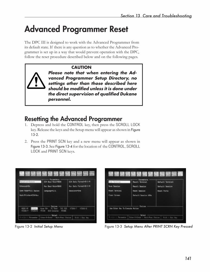
Section 13 Care and Troubleshooting
���
TheDPCIIIisdesignedtoworkwiththeAdvancedProgrammerfromitsdefaultstate.If thereisanyquestionastowhethertheAdvancedPro-grammerissetupinawaythatwouldpreventoperationwiththeDPC,followtheresetproceduredescribedbelowandonthefollowingpages.
Please note that when entering the Ad-vanced Programmer Setup Directory, no settings other than those described here should be modified unless it is done under the direct supervision of qualified Dukane personnel.
Advanced Programmer Reset
CAUTION
Resetting the Advanced Programmer1. Depress and hold the CONTROL key, then press the SCROLL LOCK
key.ReleasethekeysandtheSetupmenuwillappearasshowninFigure13-2.
2. Press the PRINT SCN keyandanewmenuwillappearasshowninFigure13-3. See Figure13-4 for the location of the CONTROL, SCROLL LOCK and PRINT SCN keys.
Figure13-2 Initial Setup Menu Figure13-3 Setup Menu After PRINT SCRN Key Pressed
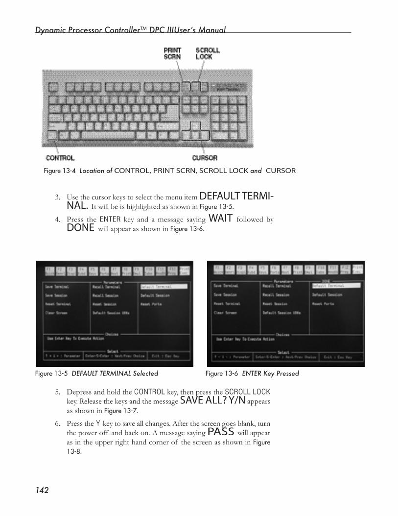
Dynamic Processor ControllerTM DPC IIIUser’s Manual
���
Figure13-5 DEFAULT TERMINAL Selected Figure13-6 ENTER Key Pressed
Figure13-4 Location of CONTROL, PRINT SCRN, SCROLL LOCK and CURSOR
3. Use the cursor keys to select the menu item DEFAULT TERMI-NAL. ItwillbeishighlightedasshowninFigure13-5.
4. Press the ENTER key and a message saying WAIT followed byDONE willappearasshowninFigure13-6.
5. Depress and hold the CONTROL key, then press the SCROLL LOCK key. Release the keys and the message SAVE ALL? Y/N appears asshowninFigure13-7.
6. Press the Y key to save all changes. After the screen goes blank, turn thepoweroff andbackon.AmessagesayingPASS willappearasintheupperrighthandcornerof thescreenasshowninFigure13-8.
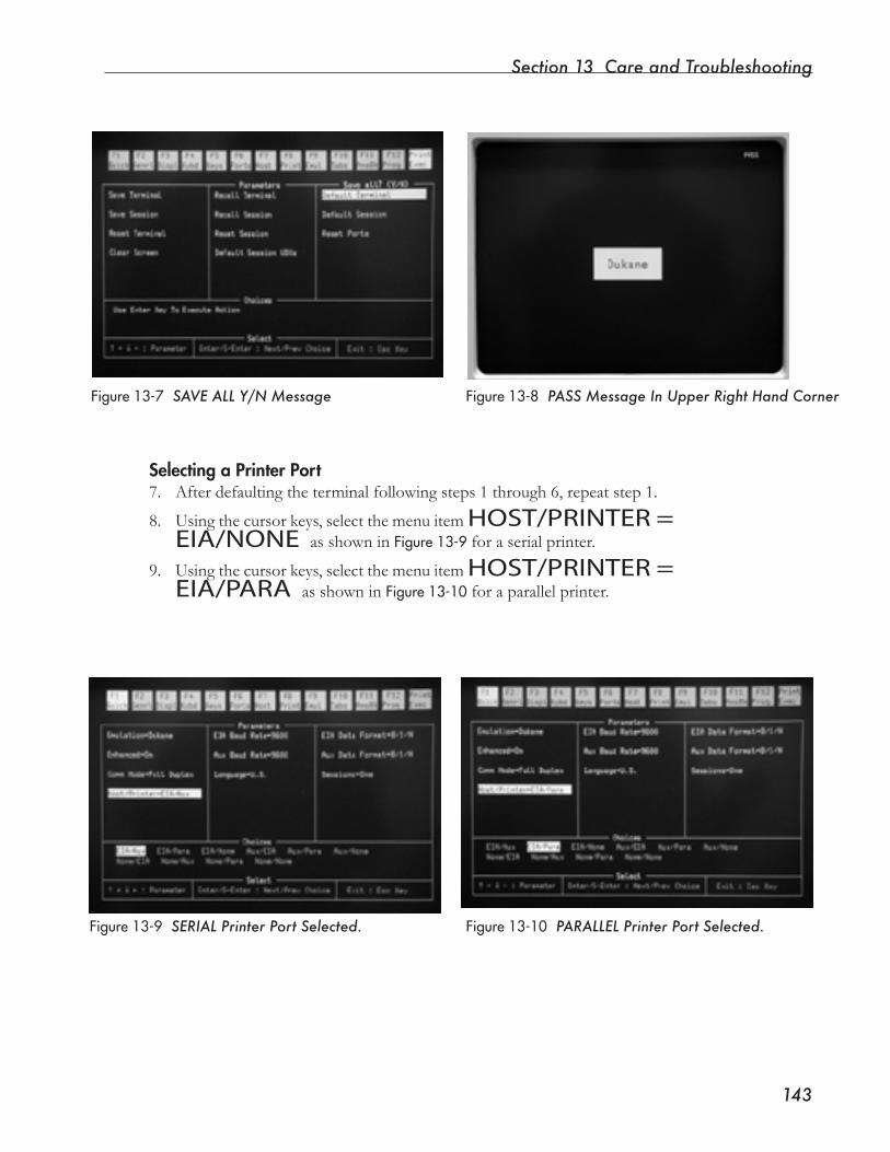
Section 13 Care and Troubleshooting
���
Figure13-7 SAVE ALL Y/N Message
Selecting a Printer Port7. Afterdefaultingtheterminalfollowingsteps1through6,repeatstep1.
8. Using the cursor keys, select the menu item HOST/PRINTER = EIA/NONE asshowninFigure13-9 for a serial printer.
9. Using the cursor keys, select the menu item HOST/PRINTER = EIA/PARA asshowninFigure13-10 for a parallel printer.
Figure13-8 PASS Message In Upper Right Hand Corner
Figure13-9 SERIAL Printer Port Selected. Figure13-10 PARALLEL Printer Port Selected.
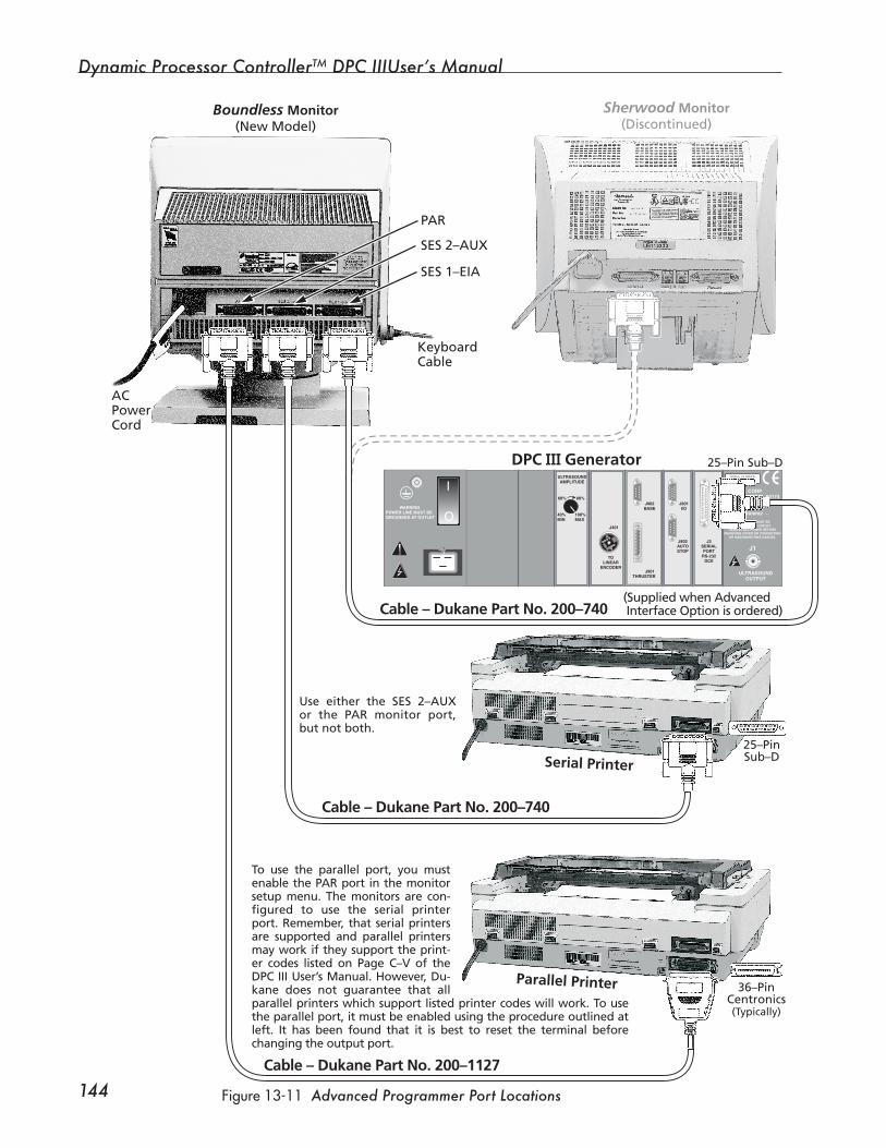
Dynamic Processor ControllerTM DPC IIIUser’s Manual
��� Figure13-11 Advanced Programmer Port Locations
Printing the Advanced Programmer Screen1. Connect a printer to the appropriate port on the rear panel of the
Advanced Programmer monitor. A serial printer connection is showninFigure2-6.Bothserialandparallelconnectionsareshownin Figure13-11.Theprintershouldautomaticallyprintouteachnewweldcycledisplayedonthescreen.
2. To print the current monitor screen image, press and hold the CONTROL(Ctrl) key.
3. While holding the CONTROL key, press the letter “P” key.
4. If you are having problems, make sure –
A. Cable connections are correct (see Figure 13–11).
B. The keyboard is connected to the terminal.
C. The DPC, monitor and printer are all turned on.
D. The connections are secure.
The Advanced Programmer is factory configured to use the se-rial printer port. Remember, that serial printers are supported and parallel printers may work if they support the printer codes listed on Page C–V of this manual. However, Dukane does not guarantee that all parallel printers which support the listed printer codes will work. To use the parallel port, it must be enabled using the procedure outlined. It has been found that it is best to default the terminal (Steps 1–6) before changing the output port in Steps 7–9. Only one of the output ports, serial (preferred) or parallel can be enabled at a time.
WARNINGPOWER LINE MUST BEGROUNDED AT OUTLET
– WARNING! –
POWER LINE MUST BEGROUNDED AT OUTLET.
REMOVE ALL POWER BEFOREREMOVING COVER OR CONNECTING
OR DISCONNECTING CABLES.
J1
ULTRASOUNDOUTPUT
TOLINEAR
ENCODER
J401
J901THRUSTER
J902BASE
J801I/O
J802AUTOSTOP
J3SERIALPORT
RS-232DCE
40%MIN
100%MAX
60% 80%
ULTRASOUNDAMPLITUDE
DUKANE CORPST. CHARLES, IL 60174MADE IN USA
SERIAL NUMBER US 123456
O
I
Sherwood Monitor(Discontinued)
Serial Printer
(Supplied when Advanced Interface Option is ordered)
Cable – Dukane Part No. 200–740
Cable – Dukane Part No. 200–740
Cable – Dukane Part No. 200–1127
Parallel Printer
Boundless Monitor(New Model)
SES 1–EIA
KeyboardCable
ACPowerCord
PAR
SES 2–AUX
25–Pin Sub–D
25–PinSub–D
36–PinCentronics(Typically)
DPC III Generator
Use either the SES 2–AUX or the PAR monitor port, but not both.
To use the parallel port, you must enable the PAR port in the monitor setup menu. The monitors are con-figured to use the serial printer port. Remember, that serial printers are supported and parallel printers may work if they support the print-er codes listed on Page C–V of the DPC III User’s Manual. However, Du-kane does not guarantee that all parallel printers which support listed printer codes will work. To use the parallel port, it must be enabled using the procedure outlined at left. It has been found that it is best to reset the terminal before changing the output port.
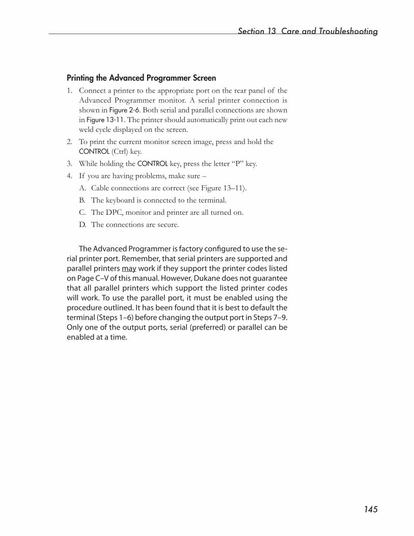
Section 13 Care and Troubleshooting
���Figure13-11 Advanced Programmer Port Locations
Printing the Advanced Programmer Screen1. Connect a printer to the appropriate port on the rear panel of the
Advanced Programmer monitor. A serial printer connection is showninFigure2-6.Bothserialandparallelconnectionsareshownin Figure13-11.Theprintershouldautomaticallyprintouteachnewweldcycledisplayedonthescreen.
2. To print the current monitor screen image, press and hold the CONTROL(Ctrl) key.
3. While holding the CONTROL key, press the letter “P” key.
4. If you are having problems, make sure –
A. Cable connections are correct (see Figure 13–11).
B. The keyboard is connected to the terminal.
C. The DPC, monitor and printer are all turned on.
D. The connections are secure.
The Advanced Programmer is factory configured to use the se-rial printer port. Remember, that serial printers are supported and parallel printers may work if they support the printer codes listed on Page C–V of this manual. However, Dukane does not guarantee that all parallel printers which support the listed printer codes will work. To use the parallel port, it must be enabled using the procedure outlined. It has been found that it is best to default the terminal (Steps 1–6) before changing the output port in Steps 7–9. Only one of the output ports, serial (preferred) or parallel can be enabled at a time.
WARNINGPOWER LINE MUST BEGROUNDED AT OUTLET
– WARNING! –
POWER LINE MUST BEGROUNDED AT OUTLET.
REMOVE ALL POWER BEFOREREMOVING COVER OR CONNECTING
OR DISCONNECTING CABLES.
J1
ULTRASOUNDOUTPUT
TOLINEAR
ENCODER
J401
J901THRUSTER
J902BASE
J801I/O
J802AUTOSTOP
J3SERIALPORT
RS-232DCE
40%MIN
100%MAX
60% 80%
ULTRASOUNDAMPLITUDE
DUKANE CORPST. CHARLES, IL 60174MADE IN USA
SERIAL NUMBER US 123456
O
I
Sherwood Monitor(Discontinued)
Serial Printer
(Supplied when Advanced Interface Option is ordered)
Cable – Dukane Part No. 200–740
Cable – Dukane Part No. 200–740
Cable – Dukane Part No. 200–1127
Parallel Printer
Boundless Monitor(New Model)
SES 1–EIA
KeyboardCable
ACPowerCord
PAR
SES 2–AUX
25–Pin Sub–D
25–PinSub–D
36–PinCentronics(Typically)
DPC III Generator
Use either the SES 2–AUX or the PAR monitor port, but not both.
To use the parallel port, you must enable the PAR port in the monitor setup menu. The monitors are con-figured to use the serial printer port. Remember, that serial printers are supported and parallel printers may work if they support the print-er codes listed on Page C–V of the DPC III User’s Manual. However, Du-kane does not guarantee that all parallel printers which support listed printer codes will work. To use the parallel port, it must be enabled using the procedure outlined at left. It has been found that it is best to reset the terminal before changing the output port.

Dynamic Processor ControllerTM DPC IIIUser’s Manual
���
Verifying Module OperationDependingontheconfigurationof yoursystem,theDPCcontainsseveral modules that provide interfaces from the DPC main digital board to encoders and transducers outside the system. These mod-ulesincludethefollowing:• Distance Module
• Energy/PowerModule
• Pressure Transducer
• Force Transducer (Load Cell)Eachof thesemoduleshasacorresponding“view”optionintheDPCmenustructure.Theviewoptionallowsyoutoseethecurrentvalue of a control/monitor parameter to determine if the module is operating correctly.
Distance ModuleToviewthecurrentencoderposition,selecttheENCODERPOSITION menu item from the ENCODERUTILITIESsection of the Utilities Page. Viewthepositionontherightof theFrontPaneldisplayorontheStatus Line of the Advanced Programmer. As the thruster head movesupordown,thedisplayedvaluechanges.Thevalueshouldincreaseastheheadtravelsdownanddecreaseastheheadtravelsup.Uponpower-up,thedistancevalueinternaltotheDPCissetto-2.4inches. This guarantees that the DPC does not “see” a useful number until the reference mark on the distance encoder is crossed.
To check all encoder functions, either remove air pressure from the pressordepresstheEmergencyStopswitchthatisgroupedwiththeactivationswitches.Afterthepressheadisinthedownposition,switchoff powertotheDPC.SwitchthepowertotheDPConagain,andfromtheUtilitiesPage menu, select ENCODERPOSITION.The positionshould get increasingly negative until the reference mark is crossed at the top of the stroke. When the reference mark is crossed, the encoder value goes to zero and then becomes negative as the head continues up.(The reference mark is enabled upon start-up.)
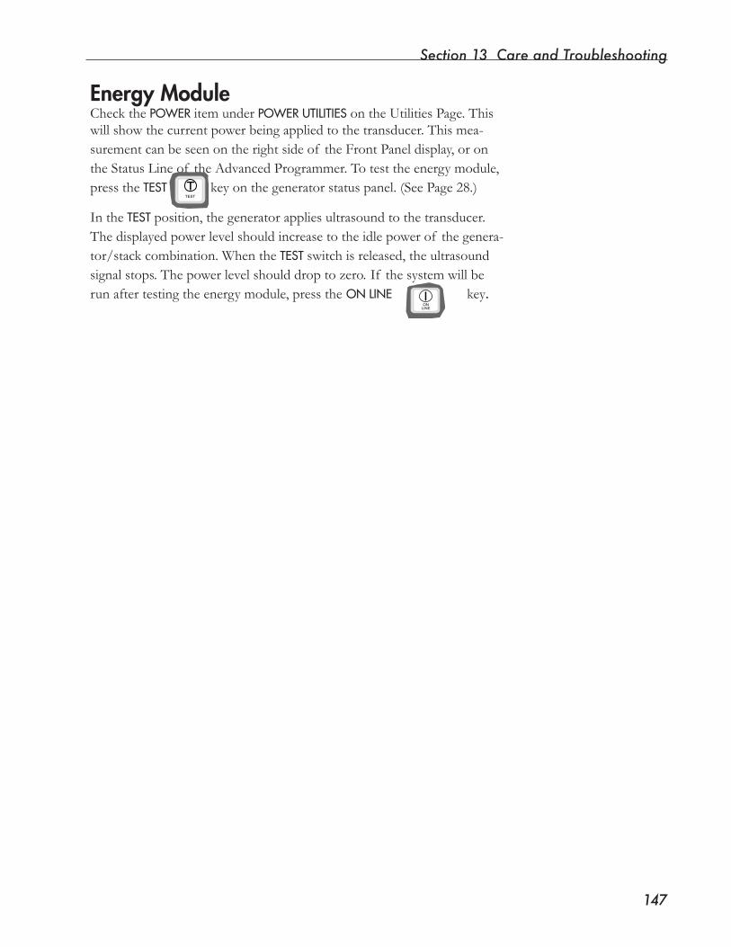
Section 13 Care and Troubleshooting
���
Energy ModuleCheck the POWERitem under POWERUTILITIES on the Utilities Page. This willshowthecurrentpowerbeingappliedtothetransducer.Thismea-surement can be seen on the right side of the Front Panel display, or on the Status Line of the Advanced Programmer. To test the energy module, press the TEST key on the generator status panel. (See Page 28.)
In the TESTposition, the generator applies ultrasound to the transducer. Thedisplayedpowerlevelshouldincreasetotheidlepowerof thegenera-tor/stack combination. When the TESTswitchisreleased,theultrasoundsignalstops.Thepowerlevelshoulddroptozero. If thesystemwillberun after testing the energy module, press theONLINE key. ON�
LINE
TEST
Dynamic Processor ControllerTM DPC IIIUser’s Manual
���
Checking the Operation of InputsInputs can be tested by activating an input and observing the Operate Pagedisplay.Theprocedurefortestingtheinputsdependsonwheth-er the input is a control signal or a remote setup input. To see example circuitsandelectricalspecificationsfortheDPCIIIinputs,refertoAppendix A-I/O.
Control InputsForthepurposesof thisdiscussion,controlinputsare:• Auto-In,
• Cycle Stop,
•TriggerSwitch,
• End of Weld/Ground Detect,
•ActivationSwitches1and2,and
• Abort.
Each of these inputs is capable of producing an Input Active at Cycle Start error. The error mechanism can be exploited to determine if an input is being recognized by the system. A procedure for each inputisoutlinedbelowwiththeappropriatecautions.
Auto-InForcinganAuto-InsignaltotheDPCwilltestforAuto-In.Topre-ventthesystemfromgoingintocycle,applythesignalwiththeFrontPanelkeyswitchintheSETUPposition.Then,turnthekeyswitchtothe OPERATEposition. After three seconds, the error message E06:AUTOACTIVEATCYCLESTART should be displayed.
NOTE
This error message appears only if the Initiate Mode menu selection is set to AUTO.
Section 13 Care and Troubleshooting
���
Cycle StopTheCycleStopinputcanbetestedbyactivatingtheinputandwait-ingatleastthreeseconds.If theinputisworkingproperly,theerrormessage E09:CYCLESTOPATCYCLESTART should appear.
Trigger SwitchTotesttheTriggerswitchinput,placetheFrontPanelkeyswitchinthe OPERATEposition,andturntheTriggerswitchdialonthethrusterclockwiseuntilthetriggerLEDlightsonthefrontpanelof thepress.Within three seconds, the error message, E08:TRIGGERATCYCLESTART should appear.
End of Weld/Ground DetectThese inputs share the same internal circuitry. The source of the End ofWeldsignalistheEndofWeldlimitswitchlocatedinthepresshead.TheswitchisconnectedtotheDPCthroughtheJ901Opera-tional Control-to-Thruster cable. The Ground Detect input enters the DPC through the J801 Auxiliary connector. Ground Detect is generallyusedtoendtheweldincuttingapplications.TotesttheEndof Weldinput,raisetheEndof WeldlimitswitchonthepressuntilitisatthesameheightastheStrokePositionflag.TurntheFrontPanelkeyswitchtotheOPERATEpositionandwaitatleastthreeseconds.The error message, E07:EOWATCYCLESTARTshould appear. To test theGroundDetectinput,activateitwiththekeyswitchintheOPER-ATEposition,andwaitfortheerrormessage.
Activation Switches - SS1 and SS2With Initiate Mode set to MANUAL,andtheFrontPanelkeyswitchin the OPERATEposition,presseitherof theactivationswitchesforat least three seconds. Errors E04 or E05:SSxACTIVEATCYCLESTART should appear.
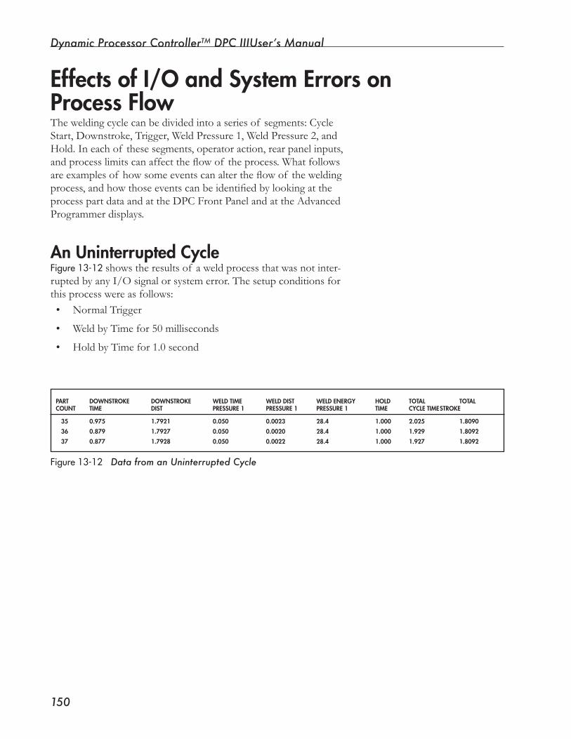
Dynamic Processor ControllerTM DPC IIIUser’s Manual
��0
Theweldingcyclecanbedividedintoaseriesof segments:CycleStart,Downstroke,Trigger,WeldPressure1,WeldPressure2,andHold. In each of these segments, operator action, rear panel inputs, andprocesslimitscanaffecttheflowof theprocess.Whatfollowsareexamplesof howsomeeventscanaltertheflowof theweldingprocess,andhowthoseeventscanbeidentifiedbylookingattheprocess part data and at the DPC Front Panel and at the Advanced Programmer displays.
An Uninterrupted CycleFigure13-12showstheresultsof aweldprocessthatwasnotinter-rupted by any I/O signal or system error. The setup conditions for thisprocesswereasfollows:• Normal Trigger
• Weld by Time for 50 milliseconds
• Hold by Time for 1.0 second
PART DOWNSTROKE DOWNSTROKE WELD TIME WELD DIST WELD ENERGy HOLD TOTAL TOTALCOUNT TIME DIST PRESSURE 1 PRESSURE 1 PRESSURE 1 TIME CyCLE TIME STROKE
35 0.975 1.7921 0.050 0.0023 28.4 1.000 2.025 1.8090
36 0.879 1.7927 0.050 0.0020 28.4 1.000 1.929 1.8092
37 0.877 1.7928 0.050 0.0022 28.4 1.000 1.927 1.8092
Figure13-12 Data from an Uninterrupted Cycle
Effects of I/O and System Errors on Process Flow
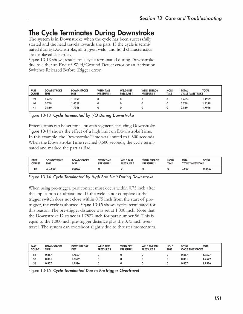
Section 13 Care and Troubleshooting
���
The Cycle Terminates During DownstrokeThesystemisinDownstrokewhenthecyclehasbeensuccessfullystartedandtheheadtravelstowardsthepart.If thecycleistermi-natedduringDownstroke,alltrigger,weld,andholdcharacteristicsare displayed as zeroes.Figure13-13showsresultsof acycleterminatedduringDownstrokedue to either an End of Weld/Ground Detect error or an Activation SwitchesReleasedBeforeTriggererror.
PART DOWNSTROKE DOWNSTROKE WELD TIME WELD DIST WELD ENERGy HOLD TOTAL TOTALCOUNT TIME DIST PRESSURE 1 PRESSURE 1 PRESSURE 1 TIME CyCLE TIME STROKE
39 0.655 1.1959 0 0 0 0 0.655 1.1959
40 0.748 1.4229 0 0 0 0 0.748 1.4229
41 0.819 1.7946 0 0 0 0 0.819 1.7946
Figure13-13 Cycle Terminated by I/O During Downstroke
ProcesslimitscanbesetforallprocesssegmentsincludingDownstroke.Figure13-14showstheeffectof ahighlimitonDownstrokeTime.Inthisexample,theDownstrokeTimewaslimitedto0.500seconds.WhentheDownstrokeTimereached0.500seconds,thecycletermi-nated and marked the part as Bad.
PART DOWNSTROKE DOWNSTROKE WELD TIME WELD DIST WELD ENERGy HOLD TOTAL TOTALCOUNT TIME DIST PRESSURE 1 PRESSURE 1 PRESSURE 1 TIME CyCLE TIME STROKE
12 >>0.500 0.3462 0 0 0 0 0.500 0.3462
Figure13-14 Cycle Terminated by High Bad Limit During Downstroke
Whenusingpre-trigger,partcontactmustoccurwithin0.75inchaftertheapplicationof ultrasound.If theweldisnotcompleteorthetriggerswitchdoesnotclosewithin0.75inchfromthestartof pre-trigger, the cycle is aborted. Figure13-15showscyclesterminatedforthisreason.Thepre-triggerdistancewassetat1.000inch.NotethattheDownstrokeDistanceis1.7527inchforpartnumber56.Thisisequaltothe1.000inchpre-triggerdistanceplusthe0.75inchover-travel. The system can overshoot slightly due to thruster momentum.
Figure13-15 Cycle Terminated Due to Pre-trigger Overtravel
PART DOWNSTROKE DOWNSTROKE WELD TIME WELD DIST WELD ENERGy HOLD TOTAL TOTALCOUNT TIME DIST PRESSURE 1 PRESSURE 1 PRESSURE 1 TIME CyCLE TIME STROKE
56 0.887 1.7527 0 0 0 0 0.887 1.7527
57 0.831 1.7522 0 0 0 0 0.831 1.7522
58 0.827 1.7516 0 0 0 0 0.827 1.7516
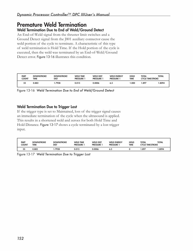
Dynamic Processor ControllerTM DPC IIIUser’s Manual
���
Premature Weld TerminationWeld Termination Due to End of Weld/Ground DetectAnEnd-of-WeldsignalfromthethrusterlimitswitchesandaGround Detect signal from the J801 auxiliary connector cause the weldportionof thecycletoterminate.Acharacteristicof thistypeof weldterminationisHoldTime.If theHoldportionof thecycleisexecuted,thentheweldwasterminatedbyanEnd-of-Weld/GroundDetect error. Figure13-16 illustrates this condition.
PART DOWNSTROKE DOWNSTROKE WELD TIME WELD DIST WELD ENERGy HOLD TOTAL TOTALCOUNT TIME DIST PRESSURE 1 PRESSURE 1 PRESSURE 1 TIME CyCLE TIME STROKE
55 0.882 1.7928 0.015 0.0006 6.5 1.000 1.897 1.8094
Figure13-16 Weld Termination Due to End of Weld/Ground Detect
Weld Termination Due to Trigger LostIf the trigger type is set to Maintained, loss of the trigger signal causes animmediateterminationof thecyclewhentheultrasoundisapplied.ThisresultsinashortenedweldandzeroesforbothHoldTimeandHold Distance. Figure13-17showsacycleterminatedbyalosttriggerinput.
Figure13-17 Weld Termination Due to Trigger Lost
PART DOWNSTROKE DOWNSTROKE WELD TIME WELD DIST WELD ENERGy HOLD TOTAL TOTALCOUNT TIME DIST PRESSURE 1 PRESSURE 1 PRESSURE 1 TIME CyCLE TIME STROKE
55 0.882 1.7928 0.015 0.0006 6.5 0 1.897 1.8094
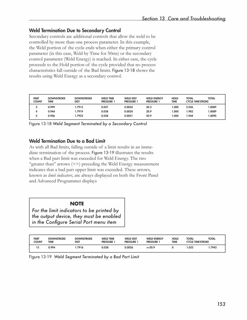
Section 13 Care and Troubleshooting
���
PART DOWNSTROKE DOWNSTROKE WELD TIME WELD DIST WELD ENERGy HOLD TOTAL TOTALCOUNT TIME DIST PRESSURE 1 PRESSURE 1 PRESSURE 1 TIME CyCLE TIME STROKE
13 0.994 1.7916 0.038 0.0026 >>20.9 0 1.032 1.7942
Figure13-19 Weld Segment Terminated by a Bad Part Limit
Weld Termination Due to Secondary ControlSecondarycontrolsareadditionalcontrolsthatallowtheweldtobecontrolled by more than one process parameter. In this example, theWeldportionof thecycleendswheneithertheprimarycontrolparameter (in this case, Weld by Time for 50ms) or the secondary control parameter (Weld Energy) is reached. In either case, the cycle proceeds to the Hold portion of the cycle provided that no process characteristics fall outside of the Bad limits. Figure13-18showstheresults using Weld Energy as a secondary control.
PART DOWNSTROKE DOWNSTROKE WELD TIME WELD DIST WELD ENERGy HOLD TOTAL TOTALCOUNT TIME DIST PRESSURE 1 PRESSURE 1 PRESSURE 1 TIME CyCLE TIME STROKE
3 0.999 1.7915 0.037 0.0024 20.3 1.000 2.036 1.8089
4 0.944 1.7919 0.038 0.0024 20.9 1.000 1.982 1.8089
5 0.906 1.7922 0.038 0.0021 20.9 1.000 1.944 1.8090
Figure13-18Weld Segment Terminated by a Secondary Control
Weld Termination Due to a Bad LimitAswithallBadlimits,fallingoutsideof alimitresultsinanimme-diate termination of the process. Figure13-19illustrates the results whenaBadpartlimitwasexceededforWeldEnergy.Thetwo“greaterthan”arrows(>>)precedingtheWeldEnergymeasurementindicatesthatabadpartupperlimitwasexceeded.Thesearrows,knownaslimit indicators,arealwaysdisplayedonboththeFrontPaneland Advanced Programmer displays
NOTEFor the limit indicators to be printed by the output device, they must be enabled in the Configure Serial Port menu item
Dynamic Processor ControllerTM DPC IIIUser’s Manual
���
MiscellaneousThe DPC Won’t CycleJustbeforeaweldcyclestarts,theDPCwaitsforaninitiatingsignal.If an initiating signal is applied and the system does not begin to cycle,checkthefollowing:
• Make sure the DPC’s Initiate Mode in the Process Control menu issettotheappropriatesetting:
MANUALif usingactivationswitches;AUTO if the system is con-figuredforusewithanautomatedsystem.
NOTE
The Initiate Mode selection must be set for eachsetup used. This is extremely important in the case of Sequenc-ing and setup selection.
• Remove all inhibiting inputs and check that no Cycle Start er-ror messages are displayed (Errors 04 - 09).
• Ensure that cabling is connected properly and that user inter-face circuitry is operating.
• MakesuretheFrontPanelkeyswitchisintheOPERATEposition. TheDPCwillnotcyclewhenthekeyswitchisintheSETUPposi-tion.
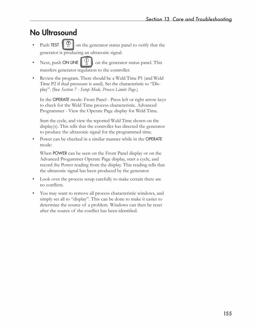
Section 13 Care and Troubleshooting
���
No Ultrasound• Push TEST on the generator status panel to verify that the
generator is producing an ultrasonic signal.
• Next, push ONLINE on the generator status panel. This
transfers generator regulation to the controller.
• Reviewtheprogram.ThereshouldbeaWeldTimeP1(andWeldTime P2 if dual presssure is used). Set the characteristic to “Dis-play”. (See Section 7 - Setup Mode, Process Limits Page.)
In the OPERATEmode:FrontPanel-Pressleftorrightarrowkeysto check for the Weld Time process characteristic. Advanced Programmer-ViewtheOperatePagedisplayforWeldTime.
Startthecycle,andviewthereportedWeldTimeshownonthedisplay(s). This tells that the controller has directed the generator to produce the ultrasonic signal for the programmed time.
• PowercanbecheckedinasimilarmannerwhileintheOPERATEmode:
When POWERcan be seen on the Front Panel display or on the Advanced Progammer Operate Page display, start a cycle, and recordthePowerreadingfromthedisplay.Thisreadingtellsthatthe ultrasonic signal has been produced by the generator.
• Look over the process setup carefully to make certain there are noconflicts.
• Youmaywanttoremoveallprocesscharacteristicwindows,andsimply set all to “display”. This can be done to make it easier to determinethesourceof aproblem.Windowscanthenberesetafterthesourceof theconflicthasbeenidentified.
ON�LINE
TEST

Dynamic Processor ControllerTM DPC IIIUser’s Manual
���
This page intentionally left blank

SECTION 14
Dukane Corporation Contacts and Warranty• This section gives Dukane Corporation contact andwarrantyinformation.
Dukane Corporation

Dynamic Processor ControllerTM DPC III Plus User’s Manual
This page intentionally left blank

Section 14 Dukane Corporation Contacts and Warranty
���
Contacting DukaneIdentify EquipmentWhen contacting Dukane about a service–related prob-lem, be prepared to give the following information:
• Model number, line voltage and serial number
• Fault/error indicators from the display
• Firmware version
• Problem description and steps taken to resolve it
Many problems can be solved over the telephone, so it is best to call from a telephone located near the equip-ment.
Intelligent Assembly SolutionsMailing Address: Dukane Ultrasonics 2900 Dukane Drive St. Charles, IL 60174 USA
Phone: (630) 797–4900
E-Mail: [email protected]
Fax: Main (630) 797–4949 Service & Parts (630) 584–0796
Website
The website has information about our products, pro-cesses, solutions, and technical data. Downloads are available for many kinds of literature. This is our main web address:
www.dukane.com/us/
You can locate your local representative at:
www.dukane.com/us/sales/intsales.htm

Dynamic Processor ControllerTM DPC IIIUser’s Manual
���
This page intentionally left blank

Section 14 Dukane Corporation Contacts and Warranty
���
Subject to the terms, limitations and exclusions set forth below, Dukane Corporation IAS Division (Dukane) warrants to the original Purchaser, unless otherwise expressly agreed to in writing by Dukane, that all equipment and tooling designed and built by Dukane will be free from defects in material or workmanship. Normal wear items are not covered by this warranty. Warranty duration shall be defined as documented herein and in conjunction with any exceptions or exclusions in the accompanying Dukane quotation to the Purchaser.
All Dukane warranties commence on the date of the original shipment of the equipment or tooling, and duration is based upon a single shift per day, five day per week operation. The warranty period on rentals of new equipment that are converted to a purchase are deemed to have commenced on the initial date of rental.
These warranties are limited to equipment and tooling operated and maintained per Dukane’s written instructions, and used under normal operating conditions. These warranties do not include normal wear or normal wear items, and do not cover damage attributable to misuse, improper installation, faulty repair, unauthorized alteration or modification, neglect, or accident. Misuse includes operation of equipment with tooling that is not qualified for the equipment or properly installed on the equipment.
The warranty on all Dukane equipment and tooling purchased and installed in North America is a parts and labor warranty only. Equipment installed outside of North America, regardless of where it was purchased, is covered by Dukane’s International Warranty Policy. In all cases, when on-site service is required, Travel & Living (T&L) expenses will be billed at cost. Warranty service labor (including travel time) at the customer’s site is provided on a Monday through Friday (excluding holidays), 7 a.m. to 7 p.m. basis. Any warranty service requested outside of these hours is available on a charge basis equal to 150% of Dukane’s prevailing rate for technical service work.
Any equipment or tooling that proves to be defective in material or workmanship during the stated warranty period will be repaired or replaced at the sole discretion of Dukane Corporation when Dukane is promptly notified in writing. During the warranty period, defective equipment, components, or tooling that are returned properly packed with all transportation charges prepaid will be repaired or replaced and returned to the end-user without charge. Shipments of warranty parts will be via standard, non-expedited delivery service. Expedited shipment requests are subject to freight charges to the Purchaser.
Computers, PLCs, CRTs, LCDs, touch screens, and keyboards separate and/or incorporated as an integral part of a system will carry a one (1) year warranty from the date of shipment when used under normal operating conditions, and not subjected to misuse, abuse, or neglect. For all other equipment, components, or parts included in equipment or systems from Dukane, but not manufactured by Dukane or its af-filiates, this warranty shall be limited in time and extent to the warranty given to Dukane by the OEM.
EQUIPMENT WARRANTY EXCLUSIONS OR EXCEPTIONS:When specified in our quotation, a limited warranty may apply to certain components of the equipment, and/or for certain types of applica-tions of the equipment, including those noted below.
❑ This warranty is void if the ultrasonic welder and/or tooling [i.e., horn(s) and fixture(s)] are used for applications requiring metal-to-metal contact, when the ultrasonic exposure period (weld cycle) exceeds 250 milliseconds.
❑ Ultrasonic Equipment and tooling used in continuous duty cycle modes such as, but not limited to, continuous cut and seal, and food processing are warranted for 2000 hours or 12 months from shipment, whichever occurs first.
❑ Any ultrasonic horn or tool quoted and sold as “Experimental” is not warranted.❑ This warranty does not cover failures of equipment and components attributable to improper cooling or overheating of the trans-
ducer.❑ Ultrasonic Horn Analyzers have a 12-month warranty.❑ Ultrasonic Transducers have a one-time replacement warranty.❑ Normal wear items and consumables excluded from any warranty coverage include, but are not limited to, filters, fuses, light bulbs,
lubricants, gaskets and seals, cast urethane fixture components, laser flashlamps, laser beam delivery optics, and lasing gases.
The forgoing warranty is the sole and exclusive warranty and is made in lieu of all other warranties, express, implied or statutory, including without limitation any warranties of merchantability, fitness for a particular purpose, description, quality, productiveness or any other warranty. The remedy set forth in this warranty policy is the sole and exclusive remedy of Purchaser and in no event shall Dukane be liable for any compensatory, consequential, special, punitive or contingent damages or for damages arising from any delay in performance by Dukane under this warranty.
Equipment Type Equipment Warranty Duration Other Comments
Custom Systems 12 months on all Dukane designed and built content Dukane standard product included in custom systems that is not part of our standard product. are covered by the applicable product warranty.
Hot Plate Welder 24 months none
Laser Welder For all laser sources, Original equipment All internal laser optics and external beam delivery manufacturer (OEM) warranty is applicable. optics are warranted for only 30 days.
Spin Welder 24 months none
Thermal Press 24 months none
Ultrasonic Welder 36 months See WARRANTY EXCLUSIONS OR EXCEPTIONS below.
Vibration Welder 24 months none
All Production 12 months, one-time replacement. (6-month, none Tooling one-time replacement for carbide tipped horns)
Prototype Tooling • All tooling made from Renshape 460 (Renwood) Prototype Renshape 460 (Renwood) tools employ are only warranted for 200 part-cycles. reusable content, and therefore remain the property • All other prototype tooling is warranted as of Dukane.
described in each specific proposal.
DUKANE CORPORATION NORTH AMERICAN WARRANTY POLICY
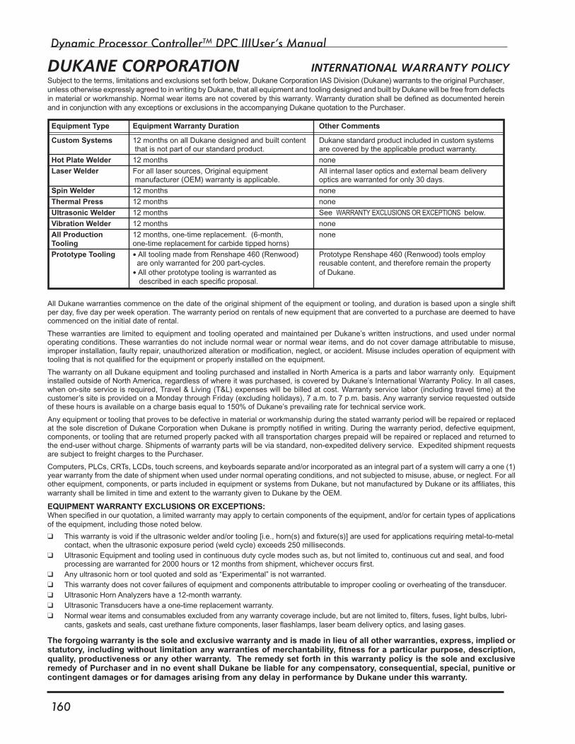
Dynamic Processor ControllerTM DPC IIIUser’s Manual
��0
Subject to the terms, limitations and exclusions set forth below, Dukane Corporation IAS Division (Dukane) warrants to the original Purchaser, unless otherwise expressly agreed to in writing by Dukane, that all equipment and tooling designed and built by Dukane will be free from defects in material or workmanship. Normal wear items are not covered by this warranty. Warranty duration shall be defined as documented herein and in conjunction with any exceptions or exclusions in the accompanying Dukane quotation to the Purchaser.
All Dukane warranties commence on the date of the original shipment of the equipment or tooling, and duration is based upon a single shift per day, five day per week operation. The warranty period on rentals of new equipment that are converted to a purchase are deemed to have commenced on the initial date of rental.
These warranties are limited to equipment and tooling operated and maintained per Dukane’s written instructions, and used under normal operating conditions. These warranties do not include normal wear or normal wear items, and do not cover damage attributable to misuse, improper installation, faulty repair, unauthorized alteration or modification, neglect, or accident. Misuse includes operation of equipment with tooling that is not qualified for the equipment or properly installed on the equipment.
The warranty on all Dukane equipment and tooling purchased and installed in North America is a parts and labor warranty only. Equipment installed outside of North America, regardless of where it was purchased, is covered by Dukane’s International Warranty Policy. In all cases, when on-site service is required, Travel & Living (T&L) expenses will be billed at cost. Warranty service labor (including travel time) at the customer’s site is provided on a Monday through Friday (excluding holidays), 7 a.m. to 7 p.m. basis. Any warranty service requested outside of these hours is available on a charge basis equal to 150% of Dukane’s prevailing rate for technical service work.
Any equipment or tooling that proves to be defective in material or workmanship during the stated warranty period will be repaired or replaced at the sole discretion of Dukane Corporation when Dukane is promptly notified in writing. During the warranty period, defective equipment, components, or tooling that are returned properly packed with all transportation charges prepaid will be repaired or replaced and returned to the end-user without charge. Shipments of warranty parts will be via standard, non-expedited delivery service. Expedited shipment requests are subject to freight charges to the Purchaser.
Computers, PLCs, CRTs, LCDs, touch screens, and keyboards separate and/or incorporated as an integral part of a system will carry a one (1) year warranty from the date of shipment when used under normal operating conditions, and not subjected to misuse, abuse, or neglect. For all other equipment, components, or parts included in equipment or systems from Dukane, but not manufactured by Dukane or its affiliates, this warranty shall be limited in time and extent to the warranty given to Dukane by the OEM.
EQUIPMENT WARRANTY EXCLUSIONS OR EXCEPTIONS:When specified in our quotation, a limited warranty may apply to certain components of the equipment, and/or for certain types of applications of the equipment, including those noted below.
❑ This warranty is void if the ultrasonic welder and/or tooling [i.e., horn(s) and fixture(s)] are used for applications requiring metal-to-metal contact, when the ultrasonic exposure period (weld cycle) exceeds 250 milliseconds.
❑ Ultrasonic Equipment and tooling used in continuous duty cycle modes such as, but not limited to, continuous cut and seal, and food processing are warranted for 2000 hours or 12 months from shipment, whichever occurs first.
❑ Any ultrasonic horn or tool quoted and sold as “Experimental” is not warranted.❑ This warranty does not cover failures of equipment and components attributable to improper cooling or overheating of the transducer.❑ Ultrasonic Horn Analyzers have a 12-month warranty.❑ Ultrasonic Transducers have a one-time replacement warranty.❑ Normal wear items and consumables excluded from any warranty coverage include, but are not limited to, filters, fuses, light bulbs, lubri-
cants, gaskets and seals, cast urethane fixture components, laser flashlamps, laser beam delivery optics, and lasing gases.
The forgoing warranty is the sole and exclusive warranty and is made in lieu of all other warranties, express, implied or statutory, including without limitation any warranties of merchantability, fitness for a particular purpose, description, quality, productiveness or any other warranty. The remedy set forth in this warranty policy is the sole and exclusive remedy of Purchaser and in no event shall Dukane be liable for any compensatory, consequential, special, punitive or contingent damages or for damages arising from any delay in performance by Dukane under this warranty.
Equipment Type Equipment Warranty Duration Other Comments
Custom Systems 12 months on all Dukane designed and built content Dukane standard product included in custom systems that is not part of our standard product. are covered by the applicable product warranty.
Hot Plate Welder 12 months none
Laser Welder For all laser sources, Original equipment All internal laser optics and external beam delivery manufacturer (OEM) warranty is applicable. optics are warranted for only 30 days.
Spin Welder 12 months none
Thermal Press 12 months none
Ultrasonic Welder 12 months See WARRANTY EXCLUSIONS OR EXCEPTIONS below.
Vibration Welder 12 months none
All Production 12 months, one-time replacement. (6-month, none Tooling one-time replacement for carbide tipped horns)
Prototype Tooling • All tooling made from Renshape 460 (Renwood) Prototype Renshape 460 (Renwood) tools employ are only warranted for 200 part-cycles. reusable content, and therefore remain the property • All other prototype tooling is warranted as of Dukane.
described in each specific proposal.
DUKANE CORPORATION INTERNATIONAL WARRANTY POLICY
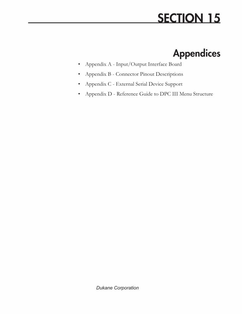
SECTION 15
Appendices• Appendix A - Input/Output Interface Board
• Appendix B - Connector Pinout Descriptions
• Appendix C - External Serial Device Support
• Appendix D - Reference Guide to DPC III Menu Structure
Dukane Corporation

Dynamic Processor ControllerTM DPC III Plus User’s Manual
This page intentionally left blank
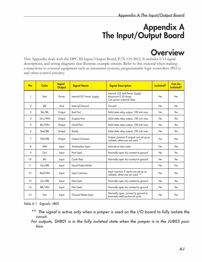
Appendix A The Input/Output Board
A-I
TableA-1 Signals: J�0�
Appendix AThe Input/Output Board
OverviewThisAppendixdealswiththeDPCIIIInput/OutputBoard, P/N 110-3812. It includes I/O signal descriptions,andwiringdiagramsthatillustrateexamplecircuits.Refertothismaterialwhenmakingconnections to external equipment such as automated systems, programmable logic controllers (PLCs) and other control circuitry.
Red
Color Isolated? Can beIsolated?Pin Signal Name Signal DescriptionInput/
Output
Blk
Blu/Blk
Red/Blk
Wht/Blk
Wht
Orn
Grn
Blu
Orn/Blk
Grn/Blk
Grn/Wht
Red/Wht
Blk/Wht
Blu/Wht
No No
No No
No No
No No
No Yes
No Yes
No Yes
No Yes
YesYes
YesYes
No Yes
No Yes
No Yes
No Yes
No Yes
1
2
3
4
5
6
7
8
9
10
11
12
13
14
15
Power
Gnd
Output
Output
Output
Output
Output
Input
Input
Input
Input
Input
Input
Input
Input
Internal DC Power Supply
Internal Ground Ground
Activate to start cycle
Solid state relay output, 100 mA max.
Solid state relay output, 100 mA max.
Solid state relay output, 100 mA max.
Solid state relay output, 100 mA max.
Normally open dry contact to ground
Normally open dry contact to ground
Normally open dry contact to ground
Normally open dry contact to ground
Normally open; connect to ground toterminate weld portion of cycle.
Input common if inputs are set up asisolated; otherwise not used. **
Output common if outputs are set up asisolated; otherwise not used. **
Ground Detect Input
Bad Part
Suspect Part
Good Part
Ready
Cycle Stop
Hand Probe Inhibit
Not Used
Not Used
Not Used
Output Common
Input Common
Automation Input
Internal +22 Volt Power SupplyMaximum 0.25 AmpsCan power external relay
** The signal is active only when a jumper is used on the I/O board to fully isolate the circuit.
For outputs, SH801 is in the fully isolated state when the jumper is in the JU803 posi-tion.
Dynamic Processor ControllerTM DPC IIIUser’s Manual
A-II
J801 Signals
J801-1 User +22 VDC SupplyThisisa+22VDC.25Acurrentlimitedsupply.
J801-2 Ground
J801-3 Bad Part Output:Theoutputisactivatedwhentheprogrammedprocesslimit(UPPERLIMIT)iseitherequaltoorgreater than the value entered in the Bad Part Limit section of the Process Limits menu. The output is alsoactivatedwhentheprogrammedprocesslimit(LOWERLIMIT)islessthanthevalueentered.
Factory Setting:Theoutputisconfiguredtosinkcurrenttochassisgroundwhenactivated.
Optional Settings:Thesystemcanbereconfiguredfor:CurrentSourcingorforFullyIsolatedOutputsby changing a jumper (SH801) on the 110-3812 I/O PCB.
NOTE
Refer to Figure A-1, Page A-VIII, for the jumper options on Current Sourcing and on Fully Isolated Output.
J801-4 Suspect Part Output:Theoutputisactivatedwhentheprogrammedprocesslimit(UPPERLIMIT)iseitherequaltoorgreater than the value entered in the Suspect Part Limit section of the Process Limits menu. The output isalsoactivatedwhentheprogrammedprocesslimit(LOWERLIMIT) is less than the value entered.
Factory Setting:Theoutputisconfiguredatthefactorytosinkcurrenttochassisgroundwhenacti-vated.
User Settings:TheusercanreconfigurethesystemforCurrentSourcingorforFullyIsolatedOutputsby changing a jumper (SH801) on the 110-3812 I/O PCB.
Appendix A The Input/Output Board
A-III
J801 Signals, continued
NOTE
Refer to Figure A-1, Page A-VIII, for the jumper options on Current Sourcing and on Fully Isolated Output.
J801-5 Good Part Output:Outputisactivatedwhennoupperorlowerlimitsareexceeded.ThisoutputcanberedefinedundertheI/Osectionof theCommunicationsPage.ThefourpossibledefinitionsareGoodPart,InDwell,In Cycle, and Sonics On.
Factory Setting:Outputisconfiguredtosinkcurrenttochassisground.
User Settings:TheusercanreconfigurethesystemforCurrentSourcingorforFullyIsolatedOutputsby changing a jumper (SH801) on the 110-3812 I/O PCB.
J801-6 Ready Output:Outputisactivatedwhenthesystemisreadytostartanewcycle.ThisoutputcanberedefinedundertheI/Osectionof theCommunicationsPage.ThefourpossibledefinitionsareReady,GoodPart,InCycle, and Sonics On.
Factory Setting:Outputisconfiguredtosinkcurrenttochassisground.
User Setting:TheusercanreconfigurethesystemforCurrentSourcingorforFullyIsolatedOutputsby changing a jumper (SH801) on the 110-3812 I/O PCB.
Do not use Ready output as the Top-of-Stroke NOTE
Dynamic Processor ControllerTM DPC IIIUser’s Manual
A-IV
J801-7 Isolated Output Common:IsolatedOutputCommonisnormallyopenunlessthesystemisreconfiguredbytheuserforFullyIsolated Outputs.
Factory Setting:Outputsareconfiguredtosinkcurrenttochassisground.
User Settings:TheusercanreconfigurethesystemforCurrentSourcingorforFullyIsolatedOutputsby changing a jumper (SH801) on the 110-3812 I/O PCB.
J801-8 Automation Input:Thisinputisusedinautomatedsystemstostartanewcycle.A50millisecondorlongeractivationpulseonthispinwillstartanewcycleandactivatetheactuator.Properguardingmustbeprovidedtopreventaccesstotheactuatorwhenthesystemisactivated.Thisinput is enabled under the Initiate menu in the Process Control portion of the setup menus. To enable this input, select AUTO under the Initiate menu.
Factory Setting:Inputisconfiguredatthefactorytosinktochassisground.
User Settings:TheusercanreconfigurethesystemforCurrentSourcingorforFullyIsolatedInputsby changing a jumper (SH802) on the 110-3812 I/O PCB.
NOTE
Refer to Figure A-1, Page A-VIII, for the jumper options on Current Sourcing and on Fully Isolated Output.
J801 Signals, continued
Appendix A The Input/Output Board
A-V
J801-10 Cycle Stop:Whenincycle,theCycleStopinputcausesanimmediateterminationof theweldcycle,andtheheadretractsunderpower.NoweldcharacteristicsarereportedtotheAdvancedProgrammerortheoutputdevice.If CycleStopissetwhenthesystemisnotincycle,allpartstatusoutputs(Bad,Suspect,andGood), are reset.
Factory Setting:Inputisconfiguredtosinktochassisground.
User Settings:TheusercanreconfigurethesystemforCurrentSourcingorforFullyIsolatedInputbychanging a jumper (SH802) on the 110-3812 I/O PCB.
J801 Signals, continued
J801-11 Hand Probe Inhibit:WhenusingahandprobeinJ801thissignalwillremovepowerfromthepressheadif itisconnectedatthe same time as a hand probe.
J801-12 Isolated Input Common:IsolatedInputCommonisnormallyopenunlessthesystemisreconfiguredbytheuserforFullyIso-lated Inputs.
Factory Setting:Inputsareconfiguredatthefactorytosinktochassisground.
User Settings:TheusercanreconfigurethesystemforCurrentSourcingorforFullyIsolatedinputsbychanging a jumper (SH802) on the 110-3812 I/O PCB.
NOTE
Refer to Figure A-1, Page A-VIII, for the jumper options on Current Sourcing and on Fully Isolated Output.
J801-15 Ground Detect Input:To activate this input, momentarily connect it to ground. When activated, the signal terminates the Weld portionof thecycle.Itisgenerallyusedtodetectwhenthehorncontactsanelectricallyisolatedanvil(fixture).Thegrounddetectinputisconnectedtotheelectricallyisolatedanvil.Whenthehorn,whichisalwaysatgroundpotential,contactstheanvil,thegrounddetectinputisactivated.
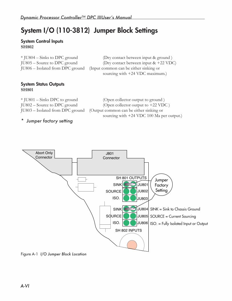
Dynamic Processor ControllerTM DPC IIIUser’s Manual
A-VI
J801 �Connector
SH 801 OUTPUTS
JU801 JU802
JU803
JU804
JU806
JU805
SINK
SOURCE �� ISO.
SINK
Abort Only �Connector
SH 802 INPUTS
SOURCE �� ISO.
JumperFactorySetting
System I/O (110-3812) Jumper Block SettingsSystem Control InputsSH802
*JU804–SinkstoDPCground (Drycontactbetweeninput&ground)JU805–SourcetoDPCground (Drycontactbetweeninput&+22VDC)JU806 – Isolated from DPC ground (Input common can be either sinking or sourcingwith+24VDCmaximum.)
System Status OutputsSH801
* JU801 – Sinks DPC to ground (Open collector output to ground )JU802–SourcetoDPCground (Opencollectoroutputto+22VDC)JU803 – Isolated from DPC ground (Output common can be either sinking or sourcingwith+24VDC100Maperoutput.)* Jumper factory setting
SINK=SinktoChassisGround
SOURCE=CurrentSourcing
ISO.=FullyIsolatedInputorOutput
FigureA-1 I/O Jumper Block Location
Appendix A The Input/Output Board
A-VII
Status SignalsReadyTheReadysignalindicatesthesystemisreadytostartanewcyclewhenitisactive. The Ready signal is on J801-6.
NOTE
The Ready signal is not the same as Top-of-Stroke. See Page 58, Figure 6-5.
Home PositionTheactuatorhasahomeortop-of-strokeswitchtoindicatetheactuatorisintheupposition.Thisindi-cateswhenitissafetoindexotherelementsof anautomatedsystem.
Other Control SignalsGround DetectGroundDetectinputonJ801-15,whenactivated,terminatestheweldportionof thecycle.Generallyitisusedtodetectwhenthehorncontactsanelectricallyisolatedanvil.GroundDetectInputisconnectedtotheelectricallyisolatedanvil.Whenthehorn,whichisalwaysatgroundpotential,contactstheanvil,thegrounddetectinputisactivated.Theweldportionof thecycleisthenterminated.Thesystemwillnotstartanewcycleuntilthegrounddetectinputisdeactivated.
Alarm SignalsTherearethreealarmsignalsavailable:GoodPart,SuspectPart,andBadPart.
ThesesignalsareatJ801-5,J801-4,andJ801-3respectively.ThesuspectpartalarmisassociatedwiththesuspectpartslimitsintheProcessLimitsmenus.Thebadpartalarmisassociatedwiththebadpartslimits in the Process Limits menus. The good part signal indicates neither suspect nor bad part limits wereexceeded.
NOTEWith the DPC buzzer set to ON, audible tones can be heard when suspect or bad parts are detected. There will not be any audible tone to signal good parts.
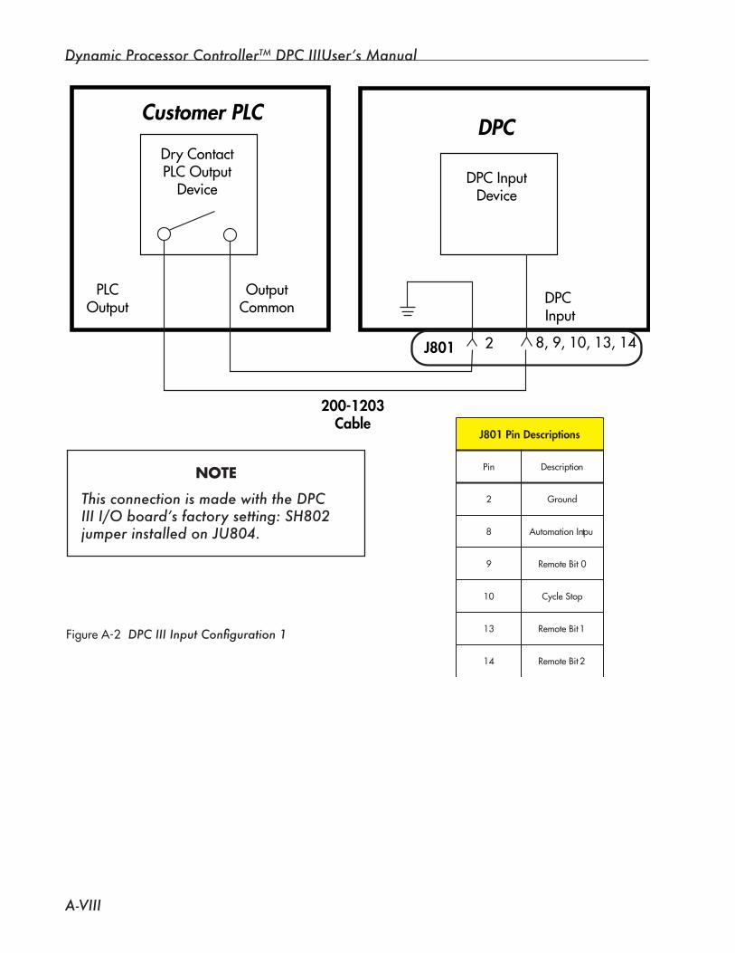
Dynamic Processor ControllerTM DPC IIIUser’s Manual
A-VIII
Customer PLC+24VDCPLCOutput
Device DPCInputDevice
DPC
PLCOutput
OutputCommon
DPCInput
J801 2 8,9,10,13,14
200-1203Cable
+24
Customer 24V
Relay
FigureA-3 DPC III Input Configuration 2
snoitpircseDniP108J
niP noitpircseD
2 dnuorG
8 t upnInoitamotuA
9 0tiBetomeR
01 potSelcyC
31 1tiBetomeR
41 2tiBetomeR
FigureA-2 DPC III Input Configuration 1
Customer PLC
DryContactPLCOutput
DeviceDPCInput
Device
DPC
PLCOutput
OutputCommon DPC
Input
J801 2 8,9,10,13,14
200-1203Cable
snoitpircseDniP108J
niP noitpircseD
2 dnuorG
8 t upnInoitamotuA
9 0tiBetomeR
01 potSelcyC
31 1tiBetomeR
41 2tiBetomeR
NOTE
This connection is made with the DPC III I/O board’s factory setting: SH802 jumper installed on JU804.
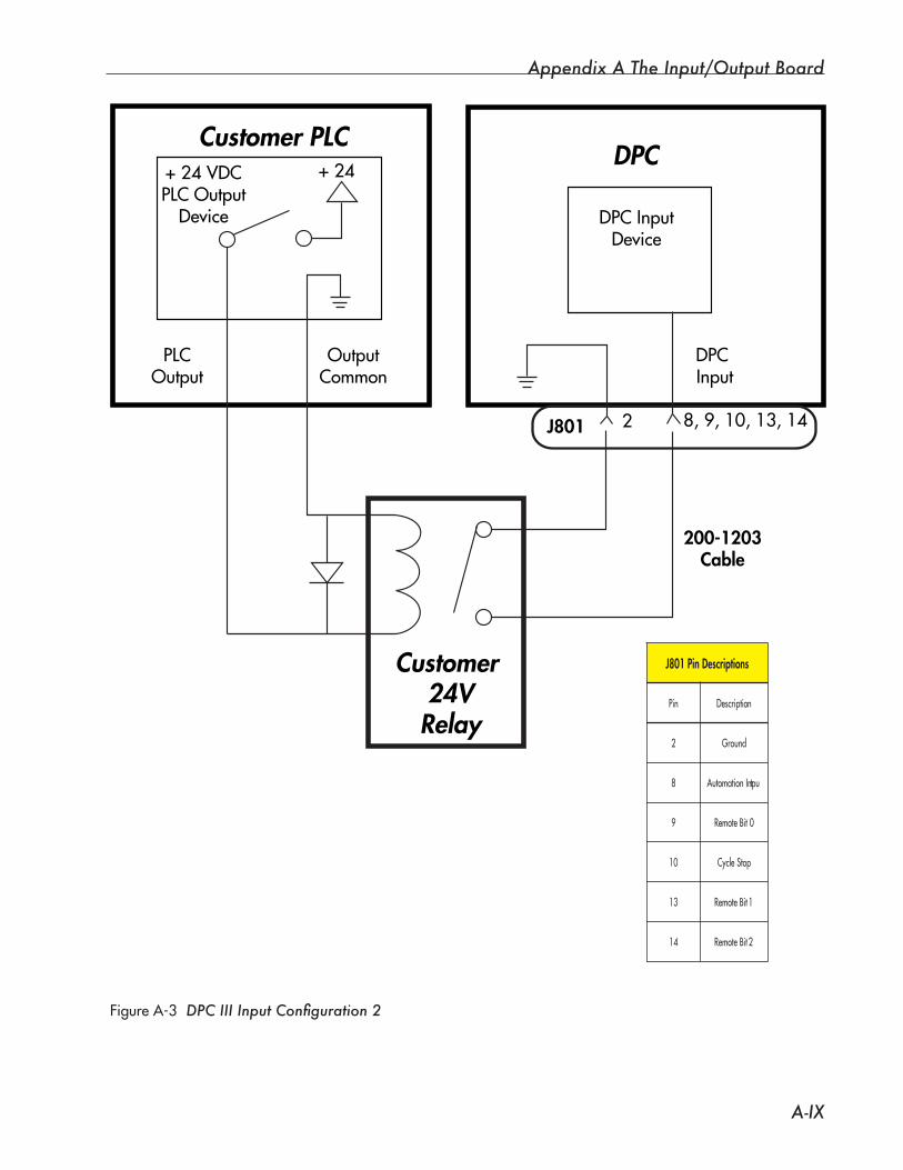
Appendix A The Input/Output Board
A-IX
Customer PLC+24VDCPLCOutput
Device DPCInputDevice
DPC
PLCOutput
OutputCommon
DPCInput
J801 2 8,9,10,13,14
200-1203Cable
+24
Customer 24V
Relay
FigureA-3 DPC III Input Configuration 2
snoitpircseDniP108J
niP noitpircseD
2 dnuorG
8 t upnInoitamotuA
9 0tiBetomeR
01 potSelcyC
31 1tiBetomeR
41 2tiBetomeR
FigureA-2 DPC III Input Configuration 1
Customer PLC
DryContactPLCOutput
DeviceDPCInput
Device
DPC
PLCOutput
OutputCommon DPC
Input
J801 2 8,9,10,13,14
200-1203Cable
snoitpircseDniP108J
niP noitpircseD
2 dnuorG
8 t upnInoitamotuA
9 0tiBetomeR
01 potSelcyC
31 1tiBetomeR
41 2tiBetomeR
NOTE
This connection is made with the DPC III I/O board’s factory setting: SH802 jumper installed on JU804.
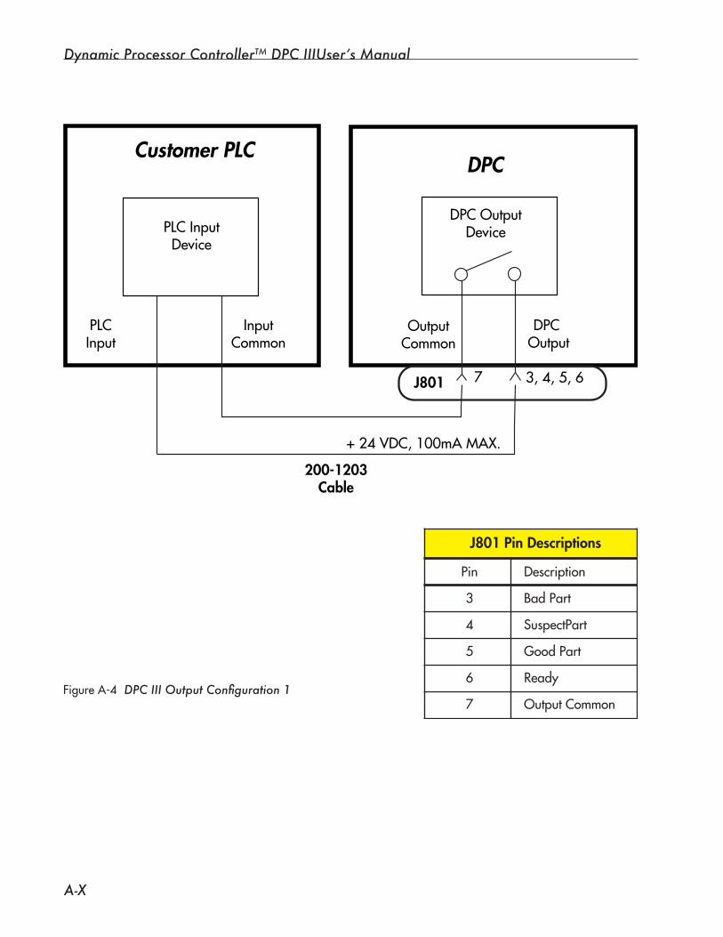
Dynamic Processor ControllerTM DPC IIIUser’s Manual
A-X
FigureA-5 DPC III Output Configuration 2
Customer PLC
DPCOutputDevice
DPC
PLCInput
InputCommon
DPCOutput
J801 7 3,4,5,6
+24V
Customer Power Supply
PLCInputDevice
200-1203Cable
+24VDC,100mAMAX.
J801 Pin Descriptions
Pin Description
3
4
5
6
7
Bad Part
SuspectPart
Good Part
Ready
Output Common
NOTE
This connection is made with an optional DPC III I/O board setting: SH801 jumper installed on JU803.
Customer PLC
PLCInputDevice
DPCOutputDevice
DPC
PLCInput
InputCommon
DPCOutput
J801 7 3,4,5,6
200-1203Cable
OutputCommon
+24VDC,100mAMAX.
FigureA-4 DPC III Output Configuration 1
J801 Pin Descriptions
Pin Description
3
4
5
6
7
Bad Part
SuspectPart
Good Part
Ready
Output Common
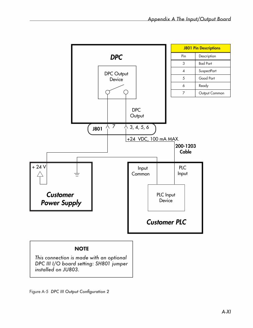
Appendix A The Input/Output Board
A-XI
FigureA-5 DPC III Output Configuration 2
Customer PLC
DPCOutputDevice
DPC
PLCInput
InputCommon
DPCOutput
J801 7 3,4,5,6
+24V
Customer Power Supply
PLCInputDevice
200-1203Cable
+24VDC,100mAMAX.
J801 Pin Descriptions
Pin Description
3
4
5
6
7
Bad Part
SuspectPart
Good Part
Ready
Output Common
NOTE
This connection is made with an optional DPC III I/O board setting: SH801 jumper installed on JU803.
Customer PLC
PLCInputDevice
DPCOutputDevice
DPC
PLCInput
InputCommon
DPCOutput
J801 7 3,4,5,6
200-1203Cable
OutputCommon
+24VDC,100mAMAX.
FigureA-4 DPC III Output Configuration 1
J801 Pin Descriptions
Pin Description
3
4
5
6
7
Bad Part
SuspectPart
Good Part
Ready
Output Common

Dynamic Processor ControllerTM DPC IIIUser’s Manual
A-XII
FigureA-6 DPC III Output Configuration 3
Customer PLC
DPCOutputDevice
DPC
PLCInput
InputCommon
DPCOutput
J801 7 3,4,5,6
+22V
PLCInputDevice
200-1203Cable
1 2
OutputCommon
JU802
J801 Pin Descriptions
Pin Description
1
2
3
4
5
6
7
Internal DC Power Ground
Internal Ground
Bad Part
SuspectPart
Good Part
Ready
Output Common
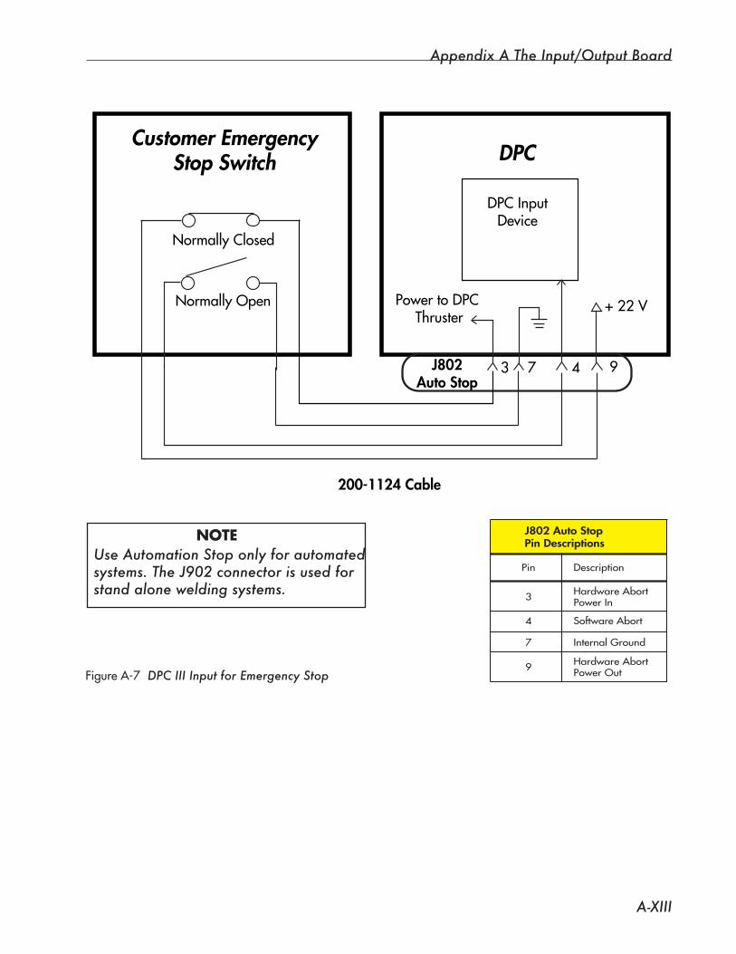
Appendix A The Input/Output Board
A-XIII
Customer EmergencyStop Switch
NormallyClosed
DPCInputDevice
DPC
J802Auto Stop
3 9
200-1124 Cable
NormallyOpen
7 4
PowertoDPCThruster
+22V
FigureA-7 DPC III Input for Emergency Stop
NOTEUse Automation Stop only for automated systems. The J902 connector is used for stand alone welding systems.
J802 Auto StopPin Descriptions
Pin Description
9
3
4
7
Hardware AbortPower Out
Hardware AbortPower In
Software Abort
Internal Ground
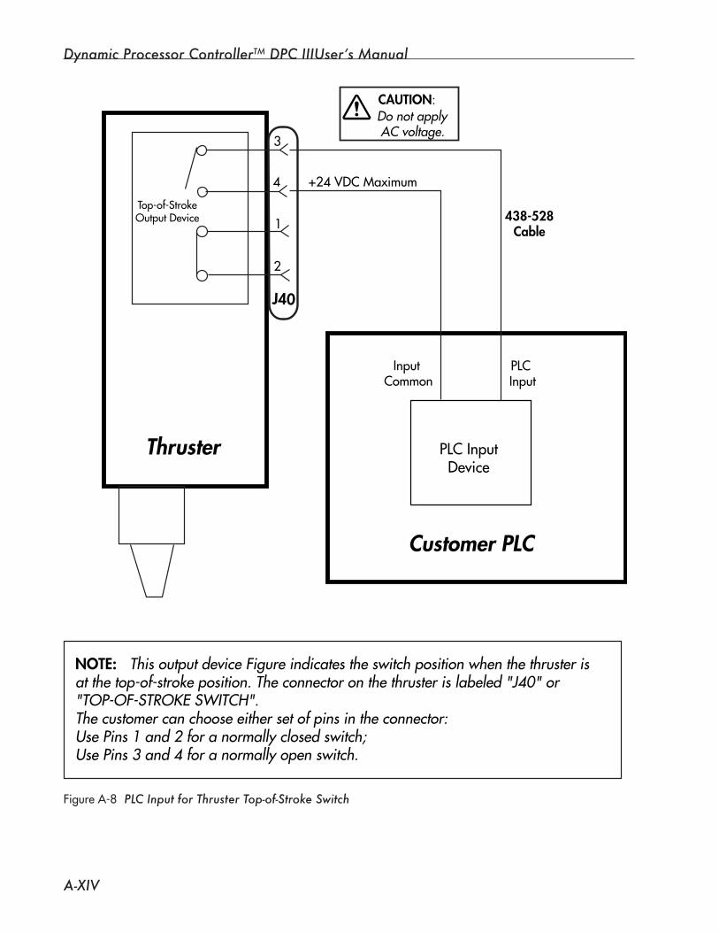
Dynamic Processor ControllerTM DPC IIIUser’s Manual
A-XIV
Thruster PLCInput
Device
Customer PLC
NOTE: This output device Figure indicates the switch position when the thruster isat the top-of-stroke position. The connector on the thruster is labeled "J40" or "TOP-OF-STROKE SWITCH".The customer can choose either set of pins in the connector:Use Pins 1 and 2 for a normally closed switch; Use Pins 3 and 4 for a normally open switch.
J40
3
4
1
2
Top-of-StrokeOutputDevice
InputCommon
PLCInput
+24VDCMaximum
Do not apply AC voltage.
CAUTION:
438-528Cable
FigureA-8 PLC Input for Thruster Top-of-Stroke Switch
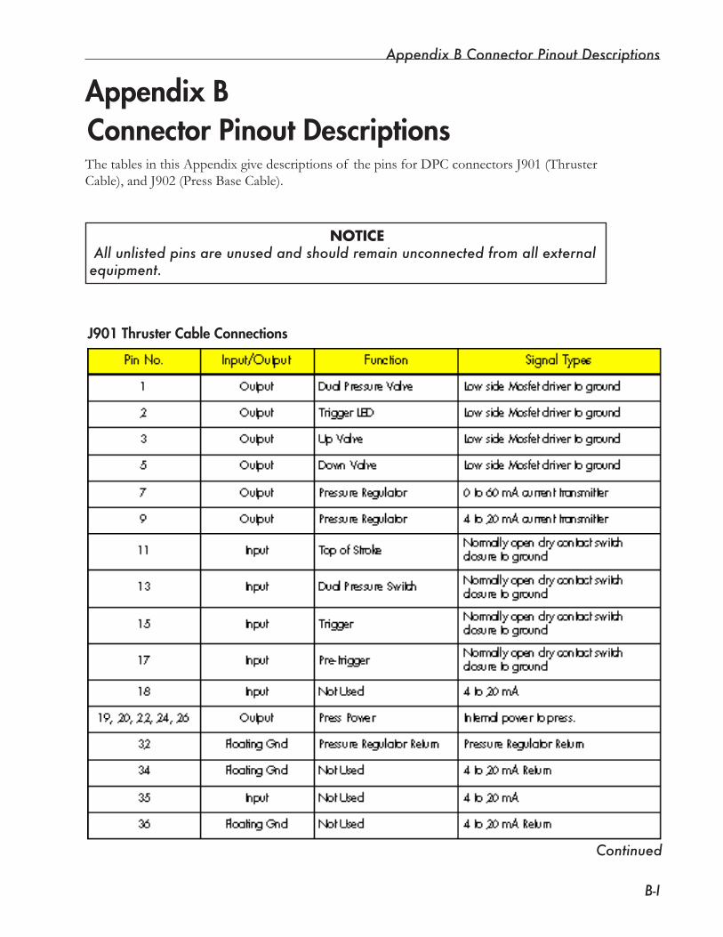
Appendix B Connector Pinout Descriptions
B-I
The tables in this Appendix give descriptions of the pins for DPC connectors J901 (Thruster Cable), and J902 (Press Base Cable).
NOTICE All unlisted pins are unused and should remain unconnected from all external equipment.
Connector Pinout Descriptions
J901 Thruster Cable Connections
Continued
Appendix B
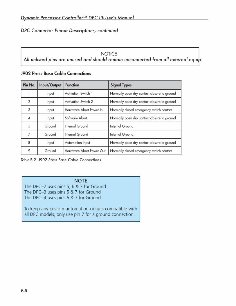
Dynamic Processor ControllerTM DPC IIIUser’s Manual
B-II
TableB-2 J�0� Press Base Cable Connections
DPC Connector Pinout Descriptions, continued
NOTICE All unlisted pins are unused and should remain unconnected from all external equip-
J902 Press Base Cable Connections
Pin No. Input/Output Function Signal Types
1 Input Activation Switch 1 Normally open dry contact closure to ground
2 Input Activation Switch 2 Normally open dry contact closure to ground
3 Input Hardware Abort Power In Normally closed emergency switch contact
4 Input Software Abort Normally open dry contact closure to ground
5 Ground Internal Ground Internal Ground
7 Ground Internal Ground Internal Ground
8 Input Automation Input Normally open dry contact closure to ground
9 Ground Hardware Abort Power Out Normally closed emergency switch contact
NOTEThe DPC–2 uses pins 5, 6 & 7 for Ground The DPC–3 uses pins 5 & 7 for Ground The DPC–4 uses pins 6 & 7 for Ground
To keep any custom automation circuits compatible with all DPC models, only use pin 7 for a ground connection.
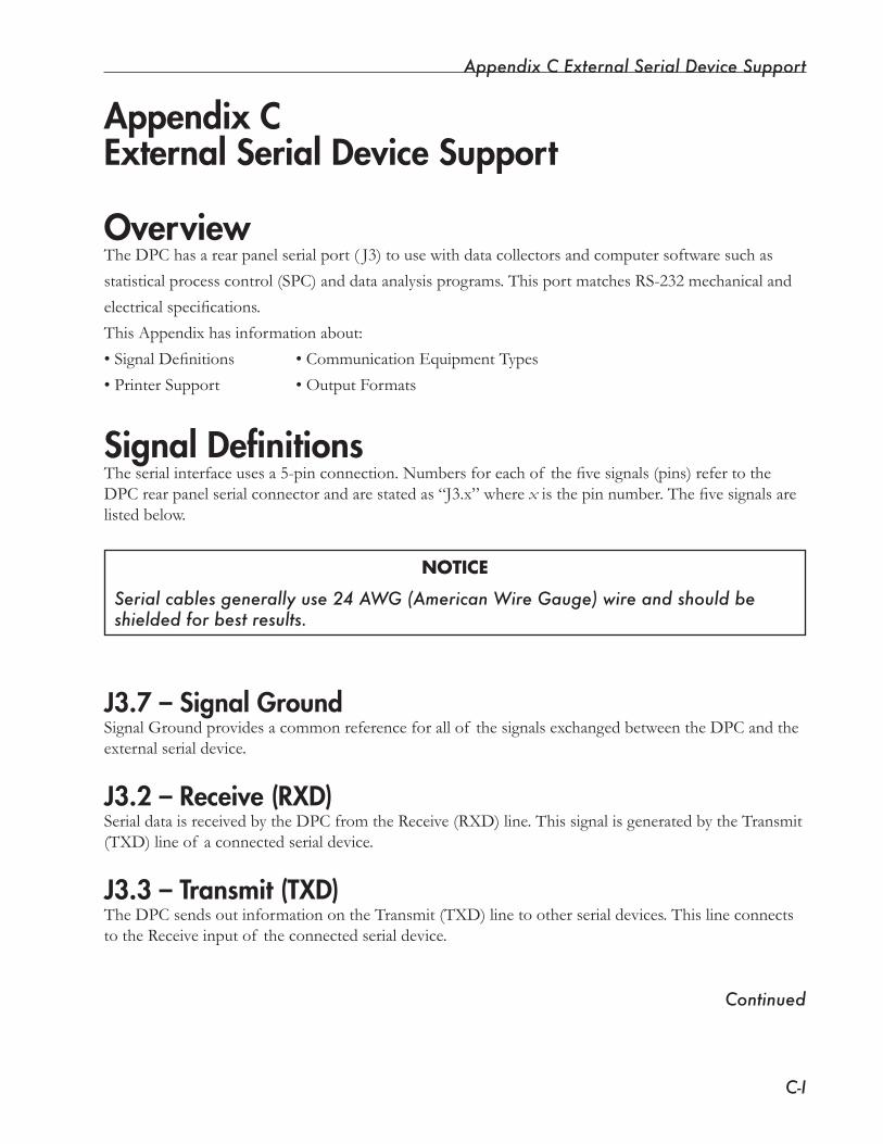
Appendix C External Serial Device Support
C-I
OverviewTheDPChasarearpanelserialport( J3)tousewithdatacollectorsandcomputersoftwaresuchas
statistical process control (SPC) and data analysis programs. This port matches RS-232 mechanical and
electricalspecifications.
ThisAppendixhasinformationabout:
•SignalDefinitions •CommunicationEquipmentTypes
• Printer Support • Output Formats
Signal DefinitionsTheserialinterfaceusesa5-pinconnection.Numbersforeachof thefivesignals(pins)refertotheDPCrearpanelserialconnectorandarestatedas“J3.x”wherexisthepinnumber.Thefivesignalsarelistedbelow.
NOTICE
Serial cables generally use 24 AWG (American Wire Gauge) wire and should be shielded for best results.
J3.7 – Signal GroundSignalGroundprovidesacommonreferenceforallof thesignalsexchangedbetweentheDPCandtheexternal serial device.
J3.2 – Receive (RXD)Serial data is received by the DPC from the Receive (RXD) line. This signal is generated by the Transmit (TXD) line of a connected serial device.
J3.3 – Transmit (TXD)The DPC sends out information on the Transmit (TXD) line to other serial devices. This line connects to the Receive input of the connected serial device.
Appendix CExternal Serial Device Support
Continued
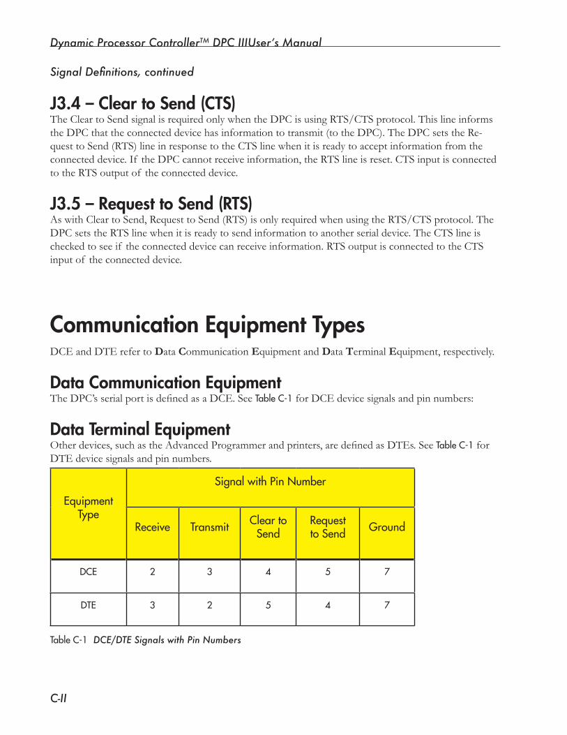
Dynamic Processor ControllerTM DPC IIIUser’s Manual
C-II
DCE and DTE refer to Data Communication Equipment and Data Terminal Equipment, respectively.
Data Communication EquipmentTheDPC’sserialportisdefinedasaDCE.SeeTableC-1forDCEdevicesignalsandpinnumbers:
Data Terminal EquipmentOtherdevices,suchastheAdvancedProgrammerandprinters,aredefinedasDTEs.SeeTableC-1 for DTE device signals and pin numbers.
TableC-1 DCE/DTE Signals with Pin Numbers
J3.4 – Clear to Send (CTS)TheCleartoSendsignalisrequiredonlywhentheDPCisusingRTS/CTSprotocol.Thislineinformsthe DPC that the connected device has information to transmit (to the DPC). The DPC sets the Re-questtoSend(RTS)lineinresponsetotheCTSlinewhenitisreadytoacceptinformationfromtheconnected device. If the DPC cannot receive information, the RTS line is reset. CTS input is connected to the RTS output of the connected device.
J3.5 – Request to Send (RTS)AswithCleartoSend,RequesttoSend(RTS)isonlyrequiredwhenusingtheRTS/CTSprotocol.TheDPCsetstheRTSlinewhenitisreadytosendinformationtoanotherserialdevice.TheCTSlineischecked to see if the connected device can receive information. RTS output is connected to the CTS input of the connected device.
Communication Equipment Types
EquipmentType
SignalwithPinNumber
Receive Transmit CleartoSend
RequesttoSend Ground
DCE 2 3 4 5 7
DTE 3 2 5 4 7
Signal Definitions, continued
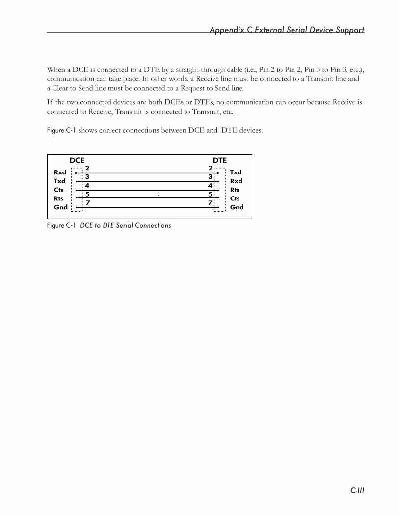
Appendix C External Serial Device Support
C-III
FigureC-1DCE to DTE Serial Connections
DCE DTE23457
23
54
7
Rxd
CtsTxd
RtsGnd
Txd
Rts
Gnd
Rxd
Cts
When a DCE is connected to a DTE by a straight-through cable (i.e., Pin 2 to Pin 2, Pin 3 to Pin 3, etc.), communicationcantakeplace.Inotherwords,aReceivelinemustbeconnectedtoaTransmitlineanda Clear to Send line must be connected to a Request to Send line.
If thetwoconnecteddevicesarebothDCEsorDTEs,nocommunicationcanoccurbecauseReceiveisconnected to Receive, Transmit is connected to Transmit, etc.
FigureC-1showscorrectconnectionsbetweenDCEandDTEdevices.
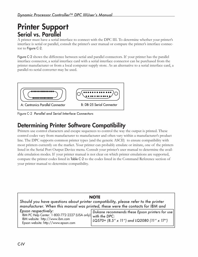
Dynamic Processor ControllerTM DPC IIIUser’s Manual
C-IV
Printer SupportSerial vs. ParallelAprintermusthaveaserialinterfacetoconnectwiththeDPCIII.Todeterminewhetheryourprinter’sinterface is serial or parallel, consult the printer’s user manual or compare the printer’s interface connec-tor to FigureC-2.
FigureC-2showsthedifferencebetweenserialandparallelconnectors.If yourprinterhastheparallelinterfaceconnector,aserialinterfacecardwithaserialinterfaceconnectorcanbepurchasedfromtheprinter manufacturer or from a local computer supply store. As an alternative to a serial interface card, a parallel-to-serial converter may be used.
Determining Printer Software CompatibilityPrintersusecontrolcharactersandescapesequencestocontrolthewaytheoutputisprinted.Thesecontrolcodesvaryfrommanufacturertomanufacturerandoftenvarywithinamanufacturer’sproductline.TheDPCsupportscommonprintertypes(andthegenericASCII)toensurecompatibilitywithmost printers currently on the market. Your printer can probably emulate or imitate, one of the printers listed in the Serial Port Output Device menu. Consult your printer’s user manual to determine the avail-ableemulationmodes.If yourprintermanualisnotclearonwhichprinteremulationsaresupported,compare the printer codes listed in TableC-2 to the codes listed in the Command Reference section of your printer manual to determine compatibility.
FigureC-2 Parallel and Serial Interface Connectors
A:CentronicsParallelConnector B:DB-25SerialConnector
Should you have questions about printer compatibility, please refer to the printer manufacturer. When this manual was printed, these were the contacts for IBM and Epson respectively:
IBMPCHelpCenter:1-800-772-2227(USAonly)IBMwebsite: http://www.ibm.comEpsonwebsite:http://www.epson.com
NOTE
Dukane recommends these Epson printers for use with the DPC:LQ570+ (8.5” x 11”) and LQ2080 (11” x 17”)
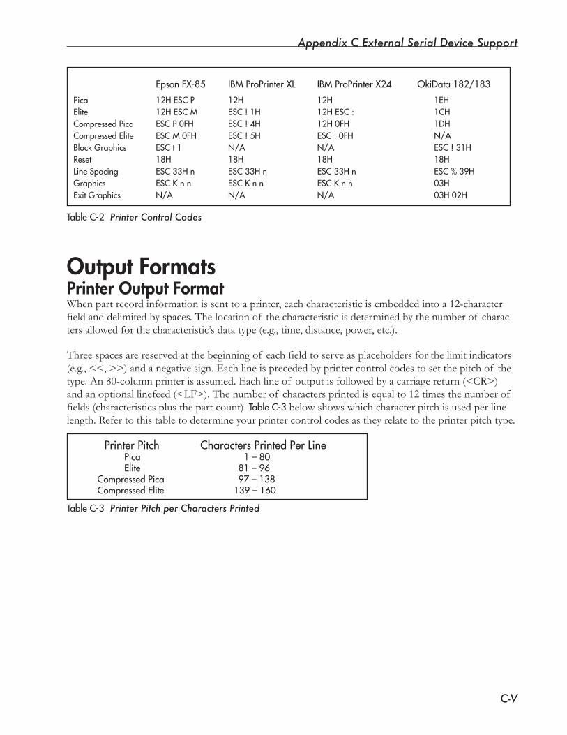
Appendix C External Serial Device Support
C-V
EpsonFX-85 IBMProPrinterXL IBMProPrinterX24 OkiData182/183
Pica 12HESCP 12H 12H 1EHElite 12HESCM ESC!1H 12HESC: 1CHCompressedPica ESCP0FH ESC!4H 12H0FH 1DHCompressedElite ESCM0FH ESC!5H ESC:0FH N/ABlockGraphics ESCt1 N/A N/A ESC!31HReset 18H 18H 18H 18HLineSpacing ESC33Hn ESC33Hn ESC33Hn ESC%39HGraphics ESCKnn ESCKnn ESCKnn 03HExitGraphics N/A N/A N/A 03H02H
TableC-2 Printer Control Codes
Output FormatsPrinter Output FormatWhen part record information is sent to a printer, each characteristic is embedded into a 12-character fieldanddelimitedbyspaces.Thelocationof thecharacteristicisdeterminedbythenumberof charac-tersallowedforthecharacteristic’sdatatype(e.g.,time,distance,power,etc.).
Threespacesarereservedatthebeginningof eachfieldtoserveasplaceholdersforthelimitindicators(e.g.,<<,>>)andanegativesign.Eachlineisprecededbyprintercontrolcodestosetthepitchof thetype.An80-columnprinterisassumed.Eachlineof outputisfollowedbyacarriagereturn(<CR>)andanoptionallinefeed(<LF>).Thenumberof charactersprintedisequalto12timesthenumberof fields(characteristicsplusthepartcount).TableC-3belowshowswhichcharacterpitchisusedperlinelength. Refer to this table to determine your printer control codes as they relate to the printer pitch type.
PrinterPitch CharactersPrintedPerLine Pica 1–80 Elite 81–96 CompressedPica 97–138 CompressedElite 139–160
TableC-3 Printer Pitch per Characters Printed
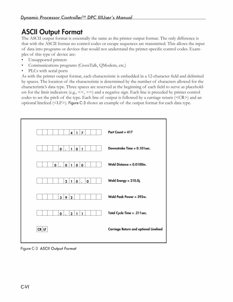
Dynamic Processor ControllerTM DPC IIIUser’s Manual
C-VI
ASCII Output FormatThe ASCII output format is essentially the same as the printer output format. The only difference is thatwiththeASCIIformatnocontrolcodesorescapesequencesaretransmitted.Thisallowstheinputof dataintoprogramsordevicesthatwouldnotunderstandtheprinter-specificcontrolcodes.Exam-plesof thistypeof deviceare:• Unsupported printers• Communicationsprograms(CrossTalk,QModem,etc.)• PLCswithserialportsAswiththeprinteroutputformat,eachcharacteristicisembeddedina12-characterfieldanddelimitedbyspaces.Thelocationof thecharacteristicisdeterminedbythenumberof charactersallowedforthecharacteristic’sdatatype.Threespacesarereservedatthebeginningof eachfieldtoserveasplacehold-ersforthelimitindicators(e.g.,<<,>>)andanegativesign.Eachlineisprecededbyprintercontrolcodestosetthepitchof thetype.Eachlineof outputisfollowedbyacarriagereturn(<CR>)andanoptionallinefeed(<LF>).FigureC-3showsanexampleof theoutputformatforeachdatatype.
FigureC-3 ASCII Output Format
0
00 1 1.
00 1.
CR LF
93
74 1
0 0
001 .2
1 1. 2
Part Count = 417
Downstroke Time = 0.101sec.
Weld Distance = 0.0100in.
Weld Energy = 210.0j.
Weld Peak Power = 392w.
Total Cycle Time = .211sec.
Carriage Return and optional Linefeed
2
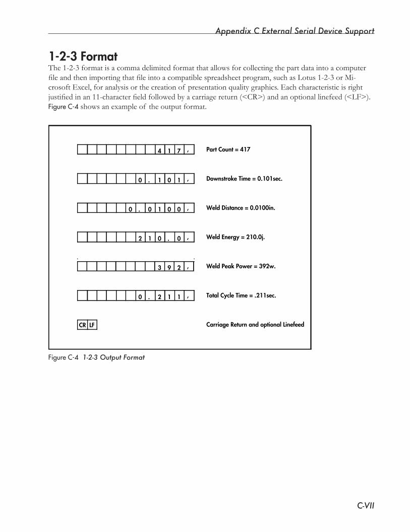
Appendix C External Serial Device Support
C-VII
1-2-3 FormatThe1-2-3formatisacommadelimitedformatthatallowsforcollectingthepartdataintoacomputerfileandthenimportingthatfileintoacompatiblespreadsheetprogram,suchasLotus1-2-3orMi-crosoft Excel, for analysis or the creation of presentation quality graphics. Each characteristic is right justifiedinan11-characterfieldfollowedbyacarriagereturn(<CR>)andanoptionallinefeed(<LF>).FigureC-4showsanexampleof theoutputformat.
FigureC-4 1-2-3 Output Format
4
00 1 1.
00 1.
CR LF
93
71
0 0
001 .2
0 1 1. 2
Part Count = 417
Downstroke Time = 0.101sec.
Weld Distance = 0.0100in.
Weld Energy = 210.0j.
Weld Peak Power = 392w.
Total Cycle Time = .211sec.
Carriage Return and optional Linefeed
2
,
,
,
,
,
,

Dynamic Processor ControllerTM DPC IIIUser’s Manual
C-VIII
CSV or LKI Format (Also known as LKS for Lyle-Kearsly Systems) LKI(alsoknownasLKSfor Lyle-Kearsly Systems) is a CSV (Comma Separated Value) format used by somestatisticalprocesscontrol(SPC)programs.Withthisformat,eachcharacteristicvalueisoutputwithanadditionaltagvalue.Thetagvalueisatwo-digitnumberuniquetothecharacteristic.Thisallowsaprogramtoidentifyeachindividualcharacteristicandstoreitinanappropriatefileregardlessoftheorderinwhichthecharacteristicisreceived.Eachlineofoutputisfollowedbyacarriagereturn(<CR>)andanoptionallinefeed(<LF>).FigureC-5showsanexampleof thisoutputformatandTableC-4 provides the tag description for each tag value.
FigureC-5 CSV Output Format
74 1
Part Count = 417
,0 0 0 0
00 1 1.
00 1.
CR LF
93
0 0
001 .2
0 1 1. 2
Downstroke Time = 0.101 second
Weld Distance = 0.0100 inch
Weld Energy = 210.0 joules
Weld Peak Power = 392 watt
Total Cycle T ime = 0.211 second
Carriage Return and optional Linefeed
2
,
,
,
,
,0
0
0
0 0
0
0
0 0 2
0
1 0
1
9
1
0 0 2 5
Tag Tag NumberDescription Decimal HexPart Count 0 00HLine Pressure 1 01HDownstrokeTime 2 02HDownstrokeDistance 3 03HContact Pressure 4 04HTrigger Delay Time 5 05HTrigger Delay Distance 6 06HReserved 7 07HWeld Time Pressure 1 8 08HWeld Distance Pressure 1 9 09HWeld Energy Pressure 1 10 0AHPeakPowerPressure1 11 0BHReserved 12 0CHWeld Time Pressure 2 13 0DHWeld Distance Pressure 2 14 0EHWeld Energy Pressure 2 15 0FHPeakPowerPressure2 16 10HReserved 17 11HAbsolute Weld Distance 18 12HTotal Weld Time 19 13HTotal Weld Distance 20 14HTotal Weld Energy 21 15HHold Time 22 16HHoldDistance 23 17HReserved 24 18HTotal Cycle Time 25 19HTotal Stroke 26 1AHTimeStampReal-TimeClock 27 1BH
TableC–4 CSV/LKI Tag Description and Tag
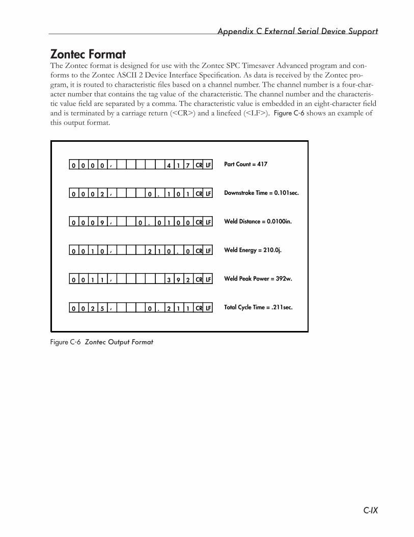
Appendix C External Serial Device Support
C-IX
Zontec FormatTheZontecformatisdesignedforusewiththeZontecSPCTimesaverAdvancedprogramandcon-formstotheZontecASCII2DeviceInterfaceSpecification.AsdataisreceivedbytheZontecpro-gram,itisroutedtocharacteristicfilesbasedonachannelnumber.Thechannelnumberisafour-char-acter number that contains the tag value of the characteristic. The channel number and the characteris-ticvaluefieldareseparatedbyacomma.Thecharacteristicvalueisembeddedinaneight-characterfieldandisterminatedbyacarriagereturn(<CR>)andalinefeed(<LF>).FigureC-6showsanexampleof this output format.
FigureC-6 Zontec Output Format
Part Count = 417
Downstroke Time = 0.101sec.
Weld Distance = 0.0100in.
Weld Energy = 210.0j.
Weld Peak Power = 392w.
Total Cycle Time = .211sec.
00 1 1.
00 1.
93
74 1
0 0
001 .2
0 1 1. 2
2
,
,
,
,
,
,
0 0 0 0
0
0
0
0 0
0
0
0 0 2
0
1 0
1
9
1
0 0 2 5
CR LF
CR LF
CR LF
CR LF
CR LF
CR LF
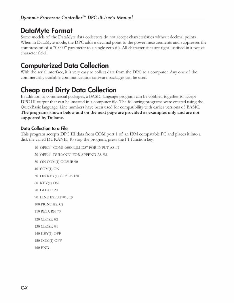
Dynamic Processor ControllerTM DPC IIIUser’s Manual
C-X
DataMyte FormatSomemodelsof theDataMytedatacollectorsdonotacceptcharacteristicswithoutdecimalpoints.WheninDataMytemode,theDPCaddsadecimalpointtothepowermeasurementsandsuppressesthecompressionof a“0.000”parametertoasinglezero(0).Allcharacteristicsareright-justifiedinatwelve-characterfield.
Computerized Data CollectionWith the serial interface, it is very easy to collect data from the DPC to a computer. Any one of the commerciallyavailablecommunicationssoftwarepackagescanbeused.
Cheap and Dirty Data CollectionIn addition to commercial packages, a BASIC language program can be cobbled together to accept DPCIIIoutputthatcanbeinsertedinacomputerfile.ThefollowingprogramswerecreatedusingtheQuickBasiclanguage.Linenumbershavebeenusedforcompatibilitywithearlierversionsof BASIC.The programs shown below and on the next page are provided as examples only and are not supported by Dukane.
Data Collection to a FileThis program accepts DPC III data from COM port 1 of an IBM compatable PC and places it into a diskfilecalledDUKANE.Tostoptheprogram,presstheF1functionkey.
10OPEN“COM1:9600,N,8,1,DS”FORINPUTAS#1
20OPEN“DUKANE”FORAPPENDAS#2
30 ON COM(1) GOSUB 90
40 COM(1) ON
50 ON KEY(1) GOSUB 120
60 KEY(1) ON
70GOTO120
90LINEINPUT#1,C$
100PRINT#2,C$
110RETURN70
120CLOSE#2
130CLOSE#1
140 KEY(1) OFF
150 COM(1) OFF
160 END
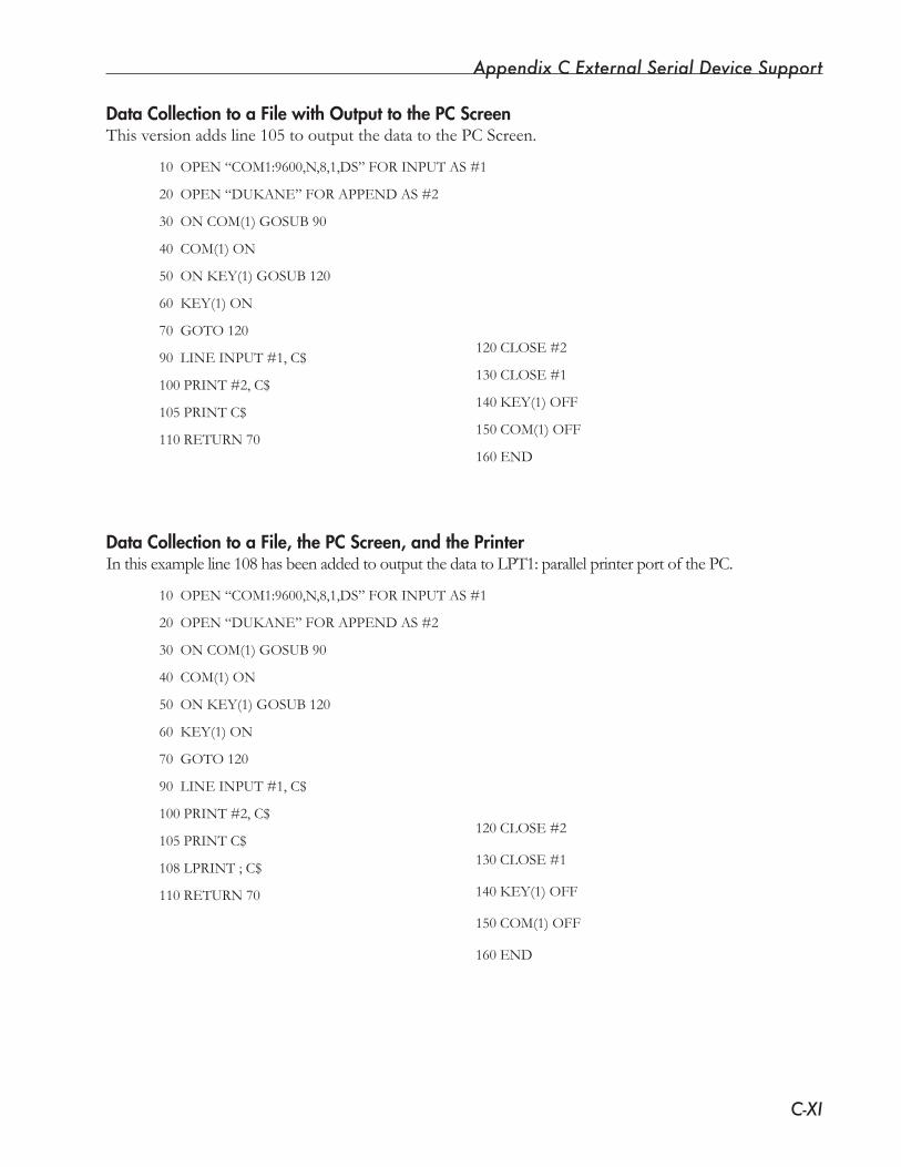
Appendix C External Serial Device Support
C-XI
Data Collection to a File with Output to the PC ScreenThis version adds line 105 to output the data to the PC Screen.
10OPEN“COM1:9600,N,8,1,DS”FORINPUTAS#1
20OPEN“DUKANE”FORAPPENDAS#2
30 ON COM(1) GOSUB 90
40 COM(1) ON
50 ON KEY(1) GOSUB 120
60 KEY(1) ON
70GOTO120
90LINEINPUT#1,C$
100PRINT#2,C$
105PRINTC$
110RETURN70
Data Collection to a File, the PC Screen, and the PrinterInthisexampleline108hasbeenaddedtooutputthedatatoLPT1:parallelprinterportofthePC.
10OPEN“COM1:9600,N,8,1,DS”FORINPUTAS#1
20OPEN“DUKANE”FORAPPENDAS#2
30 ON COM(1) GOSUB 90
40 COM(1) ON
50 ON KEY(1) GOSUB 120
60 KEY(1) ON
70GOTO120
90LINEINPUT#1,C$
100PRINT#2,C$
105PRINTC$
108LPRINT;C$
110RETURN70
120CLOSE#2
130CLOSE#1
140 KEY(1) OFF
150 COM(1) OFF
160 END
120CLOSE#2
130CLOSE#1
140 KEY(1) OFF
150 COM(1) OFF
160 END

Dynamic Processor ControllerTM DPC IIIUser’s Manual
C-XII
This page intentionally left blank.
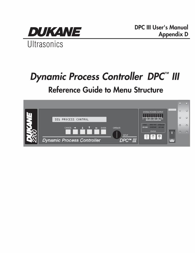
2200
STATUS
FAULT
ON LINE
INPUT TEST
OVERTEMP
OVERLOAD
OFF LINE
ONLINE TEST OFF
LINE
0 20 40 60 80 100PERCENTAGE OF AVAILABLE POWER
SYSTEM POWER OUTPUT
Dynamic Process Controller
OPERATECANCEL
SETUP
ENTER
S01 PROCESS CONTROL
DPC™ III
Ultrasonics
DPC III User's Manual Appendix D
Reference Guide to Menu Structure
Dynamic Process Controller DPC™ III
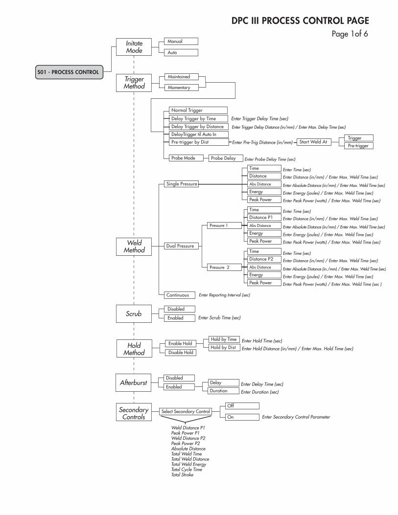
DPC III PROCESS CONTROL PAGE
InitateMode
Scrub
Manual
Auto
Maintained
Momentary
Enter Trigger Delay Time (sec)
Enter Trigger Delay Distance (in/mm) / Enter Max. Delay Time (sec)
Enter Probe Delay Time (sec)
Enter Pre-Trig Distance (in/mm)
Disabled
Enabled Enter Scrub Time (sec)
TriggerMethod
Probe Delay
Normal Trigger
Probe Mode
Delay Trigger by Distance
Delay Trigger by Time
DelayTrigger til Auto In
Pre-trigger by Dist
WeldMethod
Enter Time (sec)
Enter Distance (in/mm) / Enter Max. Weld Time (sec)
Enter Absolute Distance (in/mm) / Enter Max. Weld Time (sec)
Enter Peak Power (watts) / Enter Max. Weld Time (sec)
Enter Energy (joules) / Enter Max. Weld Time (sec)
Enter Time (sec)
Enter Distance (in/mm) / Enter Max. Weld Time (sec)
Enter Absolute Distance (in/mm) / Enter Max. Weld Time (sec)
Enter Peak Power (watts) / Enter Max. Weld Time (sec)
Enter Energy (joules) / Enter Max. Weld Time (sec)
Enter Time (sec)
Enter Distance (in/mm) / Enter Max. Weld Time (sec)
Enter Absolute Distance (in./mm) / Enter Max. Weld Time (sec)
Enter Peak Power (watts) / Enter Max. Weld Time (sec )
Enter Reporting Interval (sec)
Enter Energy (joules) / Enter Max. Weld Time (sec)
Pressure 1
Pressure 2
Time
Peak Power
Abs Distance
Distance
Energy
Time
Peak Power
Abs Distance
Distance P1
Energy
Time
Peak Power
Abs Distance
Distance P2
Energy
Dual Pressure
Single Pressure
Continuous
AfterburstDisabled
Enabled
HoldMethod
Hold by Time Enter Hold Time (sec)
Enter Hold Distance (in/mm) / Enter Max. Hold Time (sec)Hold by Dist
SecondaryControls
S01 - PROCESS CONTROL
Trigger
Pre-trigger
Enable Hold
Disable Hold
Delay Enter Delay Time (sec)
Enter Duration (sec)Duration
Off
OnSelect Secondary Control
Enter Secondary Control Parameter
Start Weld At
Weld Distance P1Peak Power P1Weld Distance P2Peak Power P2Absolute DistanceTotal Weld TimeTotal Weld DistanceTotal Weld EnergyTotal Cycle TimeTotal Stroke
DPC III PROCESS LIMITS PAGE
S01 - PROCESS LIMITS
Bad Limits
Downstroke Time
Disabled
Window
Display
Downstroke Distance
Disabled
Window
Display
Trigger Delay Time Disabled
Window
Display
Disabled
Window
Display
Weld Time P1
Low Bad Limit
High Bad Limit Enter Max Time (sec)
Enter Min Time (sec)
Disabled
Window
Display
Weld Distance P1
Weld Energy P1 Enter Max Energy (joules)
Enter Min Energy (joules)
Enter Max Distance (in)
Enter Min Distance (in)
Enter Max Power (watts)
Enter Min Power (watts)
Absolute Distance Enter Max Distance (in)
Enter Min Distance (in)
Enter Max Time (sec)Enter Min Time (sec)
Enter Max Distance (in)
Enter Min Distance (in)
Total Cycle Time
Total Stroke
Enter Max Time (sec)
Enter Min Time (sec)
Enter Max Distance (in)
Enter Min Distance (in)
Trigger Delay Dist
Low Bad Limit
High Bad Limit
Disabled
Window
Display
Low Bad Limit
High Bad Limit
Disabled
Window
Display
Weld Peak Power P1
Low Bad Limit
High Bad Limit
Disabled
Window
Display
Total Weld Energy
Hold by Distance
Hold by Time
Total Weld Time
Total Weld Distance
Low Bad Limit
High Bad Limit
Disabled
Window
Display
Low Bad Limit
High Bad Limit
Disabled
Window
Display
Low Bad Limit
High Bad Limit
Disabled
Window
Display
Low Bad Limit
High Bad Limit
Disabled
Window
Display
Enter Min Energy (joules)
Enter Max Energy (joules)
Low Bad Limit
High Bad Limit
Disabled
Window
Display
Low Bad Limit
High Bad Limit
Disabled
Window
Display
Low Bad Limit
High Bad Limit
Disabled
Window
Display
Low Bad Limit
High Bad Limit
Disabled
Window
Display
Enter Max Distance (in)
Enter Min Distance (in)
Enter Max Time (sec)
Enter Min Time (sec)
SuspectLimits Low Suspect Limit
High Suspect Limit Disabled Enabled
NOTESuspect Limits process characteristic selections are the same as those for Bad Limits.
NOTEIf the weld method is Dual Pressure, limits for Weld Time P2, Weld Distance P2,Weld Energy P2, and Weld Peak Power P2will be added.
Page1of6 Page2of6
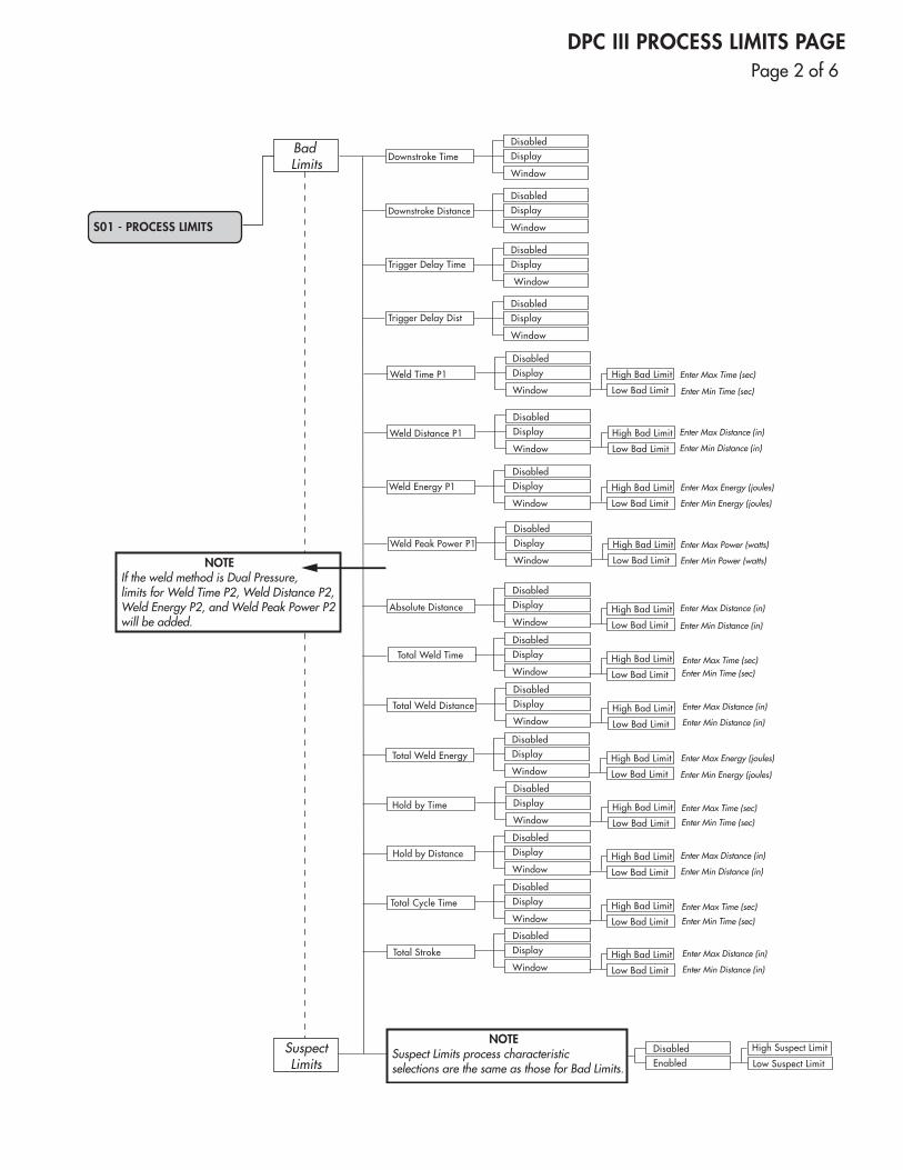
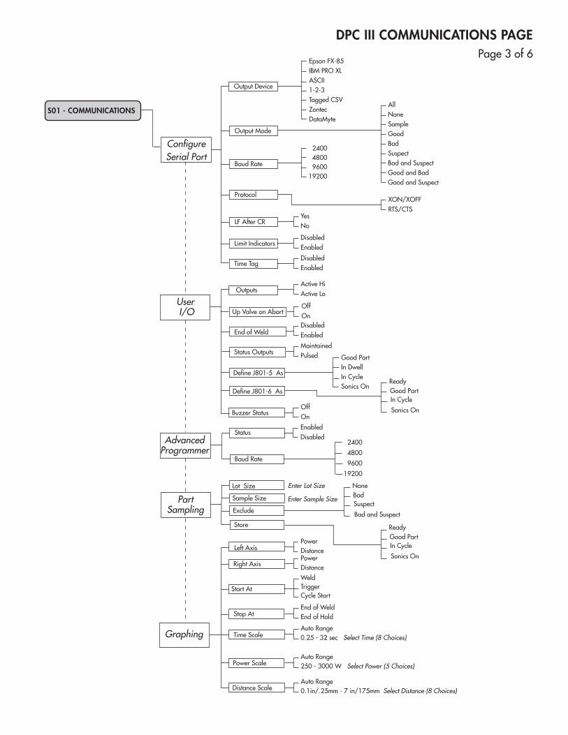
DPC III COMMUNICATIONS PAGE
PartSampling
Up Valve on Abort
Sample Size
User I/O
Outputs
AdvancedProgrammer
S01 - COMMUNICATIONS
Start At
Stop At
Left Axis
Right Axis
Time Scale
Power Scale
Distance Scale
Exclude
Store
Lot Size
ConfigureSerial Port
Time Tag
LF After CR
Limit Indicators
Baud Rate
Protocol
Output Device
Output Mode
Epson FX-85IBM PRO XLASCII1-2-3Tagged CSVZontecDataMyte
AllNone
GoodBadSuspect
Sample
Bad and SuspectGood and BadGood and Suspect
960019200
24004800
XON/XOFFRTS/CTS
YesNo
DisabledEnabled
DisabledEnabled
End of Weld
Status Outputs
Define J801-6 As
Define J801-5 As
Buzzer Status
Active HiActive Lo
OffOnDisabled Enabled
MaintainedPulsed Good Part
In DwellIn CycleSonics On
ReadyGood PartIn Cycle
Sonics OnOffOn
StatusEnabledDisabled
Baud Rate9600
19200
24004800
Enter Lot Size
Enter Sample Size
NoneBadSuspect
Bad and Suspect
ReadyGood PartIn Cycle
Sonics On
Graphing
PowerDistance
Weld
Cycle Start
End of WeldEnd of Hold
Trigger
Auto Range0.25 - 32 sec Select Time (8 Choices)
Auto Range250 - 3000 W Select Power (5 Choices)
Auto Range0.1in/.25mm - 7 in/175mm Select Distance (8 Choices)
PowerDistance
SetupUtilities
UserParameters
PowerUtilities
Copy This Setup From OK ?No
Yes
OK ?No
Yes
OK ?No
YesText
Erase Current Setup
Erase All Setups
Reset/PresetPart
Count
S01 - UTILITIES
Hex
Time andDate
Utilities
Encoder Utilities
Job I.D.
Horn
Booster
Fixture
Pressure 1
Pressure 2
Trigger Force
Power Average
Power
Enter Job Number
Enter Horn Type ( )
Enter Booster Type ( )
Enter Fixture Type ( )
Enter Pressure 1
Enter Pressure 2
Enter Trigger Force
1. Eight2. Four3. Two4. Disabled
Current Power
Enter Date
Enter Preset Part Count No. ( )
Enter Time
1. MM-DD-YY2. DD-MM-YY3. YY-MM-DD
1. English2. Metric
Displays Real Time Encoder Position
Reset Part Count
Preset Part Count
Encoder Units
Encoder Position
Print Setup
Set Date
Set Time
Check Date
Check Time
Date Format
Select a Setup No. ( )
Select a Setup No. (1-8)Select New Setup
Copy a Setup
Erase Setups
DPC III UTILITIES PAGEPage3of6 Page4of6
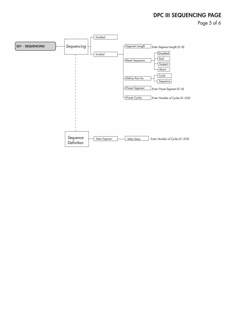
DPC III SEQUENCING PAGE
S01 - SEQUENCING Sequencing
SequenceDefinition
Disabled
Bad
Cycle
Sequence
Segment Length
Reset Sequence
Define Part As
Preset Segment
Preset Cycles
Enter Segment Length (0–8)
Enter Preset Segment (0–8)
Enter Number of Cycles (0 –255)
Suspect
Abort
Select Segment Enter Number of Cycles (0 –255)Select Setup
Disabled
Enabled
Page5of6
DPC III OPERATE PAGE
001 - PART COUNT 0 Function
Keys
Print Consecutive
Memory
PrintSample
Memory
PrintHeaders
DisplayConsecutive
Memory
DisplaySample
Memory
PrintGraph
ResetSequence
Keys F01 - F09
Key Defined
Key Undefined
Parts to Download Enter Number of Parts to Print
Parts to Download Enter Number of Parts to Print
Parts to Display Enter Number of Parts to Display
Parts to Display Enter Number of Parts to Display
No
Yes
Text
Raw Data
NOTEIn OPERATE mode, front panel display on start-up shows parameters. Use left and right arrow keys to display them.
Perform Function
Page6of6
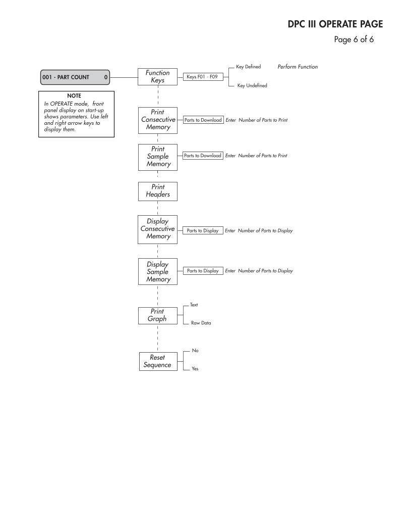

This page intentionally left blank

INDEX
Dukane Corporation

Dynamic Processor ControllerTM DPC III Plus User’s Manual
This page intentionally left blank
Index
ACPower,30NominalInput,129
AdvancedProgrammer,17–18,141–145BaudRate,93ChoosingPrinterPort,19,143Keyboard,31-34,142FunctionKey,32PrinterConnections,18,144PrintingtheScreen,145Resetting,141-143SpecialPurposeKeys,33Status,93
Afterburst,67
AmplitudeControl,21
ASCII,84
Axis,leftandright,97
BBadLimits,75
BaudRate,85
Booster,108
BuzzerStatus,92
CCableConnections,16-18,144
CommunicationsPage,81-98ConfigureSerialPort,82UserI/O,88-92AdvancedProgrammer,93PartSampling,94-96Graphing,97-98
ConnectorPinoutDescriptions,AppendixB
ControlParameters,63Time,63Distance,63AbsoluteDistance,64Energy,64PeakPower,64MaximumWeldTime,64
Controls,21-34
CopyaSetup,101
CSVFormat,C–VIII
DataMyte,84
DefineJ801-5As,90
DefineJ801-6As,91
Dimensions,128
DisplaysProcessControlPage,51ProcessLimitsPage,70CommunicationsPage,81UtilitiesPage,99SequencingPage,111OperatePage,119
DistanceEncoderUtilities,106
DPCWon’tCycle,154
DukaneCorporationPhone,Fax,E-Mail,157
A
D
Dynamic Processor ControllerTM DPC IIIUser’s Manual
EnablingProcessLimits,79
EndofWeld/GroundDetect,89
EntryFields,41-42
Environment,131
EraseSetups,101
ErrorMessages,135-139
Exclude,96
Fixture,108
FrontPanel,21-30Care,131Keypad,22-26Keyswitch,27
FunctionKeysProgramming,32Sequencing,117
GeneratorModels,129
GeneratorStatusPanel,28
GoodPart,90
Graphing,97
Grounding,7-9
HandProbe,19
HealthandSafety,6Plastics,7
HoldMethod,66
Horn,108
I/OInterfaceBoard,AppendixA
InCycle,91
InDwell,90
InitiateMode,52Manual,52Auto,53
Inputs,CheckingOperation,148-149 Installation,11-20
LFAfterCR,87
LimitIndicators,87
LotSize,94
F
G
H
I
L
E
Index
MemoryConsecutive,94Sample,94
MenuItem,40
MenuOrientation,39-48
MenuStructure,AppendixF
Menu,40
ModelNumber,130
ModuleOperation,Verifying,146-147
NavigatingInSetupMode,43-47InOperateMode,48
NewSetup,Select,100
NoUltrasound,155
1-2-3,84
OperateFunctionsFunctionKeys,122PrintPartMemory,122PrintHeaders,122DisplayPartMemory,123PrintGraph,123ResetSequence,125
OperateModeNavigatingin,48OperatePage,119-125
OperatePagewithFrontPanel,120withAdvancedProgrammer,121
OperatingEnvironment,129
OutputDevice,83
OutputMode,85
Outputs,88
Page,40
PartMemory,Display,123
PartSampling,94
PlacementBenchtop,11Rack-mount,12
PowerAverage,110
PowerConnection,20
PowerSupplyElectricalSourceRequirements,129
PowerUtilities,110 PresetCycles,115
PresetPartCount,107
PresetSegment,115
Pressure1and2,108
PrintSetup,Hex,104
M
N
O
P
Dynamic Processor ControllerTM DPC IIIUser’s Manual
PrintSetup,Text,102
PrinterCompatibility,C-IV
PrinterCableConnectiononAdvProgrammer,17-18,143
PrinterPortSelectiononAdvProgrammer,143-145
ProbeCabling,19
ProcessCharacteristics,71-74
ProcessControlPage,50-68InitiateMode,52TriggerMethod,54-60WeldMethod,61-64Scrub,65HoldMethod,66Afterburst,67SecondaryControls,68
ProcessFlow,EffectsofI/OSystemErrors,152-155
ProcessLimitsPage,69-80BadLimits,75-77SuspectLimits,77-78EnablingProcessLimits,79SecondaryControl,80
Protocol,86
Ready,91
RearPanel,13-14
RegulatoryAgencyCompliance,127
ReplaceableParts,132
ResetPartCount,107
RFIFilter,9
RTS/CTS,86
SampleSize,95
Scales,selecting,98
Scrub,65
SecondaryControl,80
SecondaryControls,68
Sequence,Whatisit?,112
SequencingPage,111-117
Sequencing,114-116
SerialDeviceSupport,AppendixC
SetupMode,49-118BlockingAccessto,34Navigatingin,43-47
ShortingBlock-HandProbe,19
SonicsOn,91
Specifications,127-130
StartAt,97
Start-up,35-38WithoutAdvancedProgrammer,35WithAdvancedProgrammer,36
S
R
Index
StatusLine,52,134
StatusOutputs,90
StopAt,97StoppingtheWeldCycle,38
Store,96
SuspectLimits,77
SystemPowerOutput,30
SystemStatus,29
TaggedCSV,84
TestingRemoteSetupSelectionInputs,151
TimeandDateUtilities,105
TimeTag,88
TriggerForce,109
TriggerMethod,54Normal,56DelaybyTime,56DelaybyDistance,57DelaytillAuto-In,57Pre-triggerbyDistance,59Probe,60
TriggerType,54Maintained,54Momentary,55
Troubleshooting,133
UserI/O,88
UserParameters,107-109
UtilitiesPage,99-110SetupUtilities,100TimeandDateUtilities,105EncoderUtilities,106Reset/PresetpartCount,107UserParameters,107PowerUtilities,110
WarningMessages,140
Warranties,159-160
WeldMethod,61-62
Xon/Xoff,86
Zontec,84
T
U
X
W
Z

Dynamic Processor ControllerTM DPC IIIUser’s Manual
This page intentionally left blank

Dukane ISOISO CERTIFICATIONDukane chose to become ISO 9001:2000 certi-fied in order to demonstrate to our customers our continuing commitment to being a quality vendor. By passing its audit, Dukane can assure you that we have in place a well–defined and systematic approach to quality design, manu-facturing, delivery and service. This certificate reinforces Dukane's status as a quality vendor of technology and products.
To achieve ISO 9001:2000 certification, you must prove to one of the quality system regis-trar groups that you meet three requirements:1. Leadership2. Involvement3. Quality in Line Organizations and Quality
System Infrastructure.
The ISO 9001:2000 standard establishes a minimum requirement for these requirements and starts transitioning the company from a traditional inspection–oriented quality system to one based on partnership for continuous improvement. This concept is key in that Du-kane no longer focuses on inspection, but on individual processes.
Dukane's quality management system is based on the following three objectives:1. Customer oriented quality. The aim is to
improve customer satisfaction.2. Quality is determined by people. The aim
is to improve the internal organization and cooperation between staff members.
3. Quality is a continuous improvement. The aim is to continuously improve the internal organization and the competitive position.
Dukane products are manufactured in ISO registered facilities
ISO 9001:2000C E R T I F I E D

Part No. 403-541-03
DukaneIntelligentAssemblySolutions•2900DukaneDriveSt.•Charles,Illinois60174USA•TEL(630)797-4900•FAX(630)797–4949
DPC III, User's Manual
PrintedintheUnitedStatesofAmerica
www.dukane.com/us
Please refer to our website at:
www.dukane.com/us/sales/intsales.htm
to locate your local representative.