intel® xeon phiâ„¢ coprocessor developer s quick start guide
TRANSCRIPT
APMP Inter-regional Key comparison: Calibration of CMM 2-D Artifacts 1
APMP.L.K6 CMM-2D Protocol (Final).doc 16 December 2009
National Metrology Institute of Japan (NMIJ, AIST)
APMP Comparison APMP.L.K6
Calibration of
Coordinate Measuring Machine (CMM) Two-dimensional (2-D) Artifacts
(Ball Plate & Hole Plate).
Technical Protocol (Final)
APMP Inter-regional Key comparison: Calibration of CMM 2-D Artifacts 2
APMP.L.K6 CMM-2D Protocol (Final).doc 16 December 2009
Contents
1. Introduction 3
2. Organization 4
2.1 Participants 4
2.2 Participants list 5
2.3 Form of comparison 7
2.4 Time table 8
2.5 Handling of artifacts 9
2.6 Transport of artifacts 10
3. Description of standards 11
3.1 Artifacts 11
3.2 Data logger 14
4. Measurement instructions 15
4.1 Traceability 15
4.2 Measurands 15
4.3 Measurement instructions 19
5. Measurement uncertainty 21
6. Reporting of results 22
Annex 23
A1 Receipt confirmation 23
A2 Report of measurements 24
A3 Measurement results 26
A4 Uncertainty of measurement 28
A5 An alternative measurement method 29
APMP Inter-regional Key comparison: Calibration of CMM 2-D Artifacts 3
APMP.L.K6 CMM-2D Protocol (Final).doc 16 December 2009
1. Introduction
1.1 The metrological equivalence of national measurement standards will be determined by a set of key comparisons chosen and organized by the Consultative Committees of the CIPM working closely with the Regional Metrology Organizations (RMOs).
1.2 The CCL inter-comparison for ball-plate and hole-plate (CCL-K6) has already been terminated, and now the report is being prepared. During the inter-comparison, the APMP/TCL decided to carry out an APMP regional comparison (APMP.L.K6) to establish equivalence of National Metrology Institutes in APMP region to the world.
1.3 In September 2003, CCL 11 decided to introduce some changes in future Key Comparisons by having inter-regional participation organized through the Regional Technical Committees for Length (RTCLs) and the WGDM, so leaving the regions in charge of their comparisons but bringing the CCL/WGDM into the loop to be able to monitor and negotiate any difficulties.
1.4 So, participants should look at other regional KC with a view to finding a) a better time to do the comparison, b) a better uncertainty range or c) a more appropriate technique or method.
1.5 This technical protocol is modelled on the previous protocols for CCL-K6 drawn by the Centro Nacional de Metrologia (CENAM), Mexico.
1.6 The procedures outlined in this document cover the technical procedure to be followed during measurement of the ball-plate and hole-plate. The procedure follows the guidelines established by the BIPM1.
1 T.J. Quinn, Guidelines for key comparisons carried out by Consultative Committees, BIPM, Paris
APMP Inter-regional Key comparison: Calibration of CMM 2-D Artifacts 4
APMP.L.K6 CMM-2D Protocol (Final).doc 16 December 2009
2. Organization 2.1 Participants 2.1.1 On 2005/Oct/7th the pilot laboratory distributed an e-mail to call for participation in the
APMP.L.K6 inter-regional comparison.
2.1.2 The participating laboratories should:
2.1.2.1 Be able to calibrate a 620 mm steel ball plate, with 5x5 ceramic 22 mm in diameter balls and 133 mm pitch between ball centers.
2.1.2.2 Be able to calibrate a 600 mm hole plate made of a low thermal expansion glass, with 44 holes, 20 mm in diameter holes and 50 mm pitch between hole centers.
2.1.2.3 Be able to demonstrate independent traceability to the realization of the meter.
2.1.3 There is an additional requirement to measure the artifacts at a temperature sufficiently close to 20 °C that the uncertainty in the measured expansion coefficient does not dominate the overall measurement uncertainty. The temperature inside the measuring volume of the CMM should have a mean inside the range 19.7 °C to 20.3 °C with variations in time and volume under 0.3 °C.
2.1.4 After agreeing on a final version of this protocol, each nominated participant must reconfirm its participation and approval of protocol. If for any of the above technical reasons a nominated laboratory is not able to participate, it must notify the pilot laboratory as soon as possible to reschedule the comparison.
2.1.5 By their declared intention to participate in this inter-regional key comparison, the laboratories accept the general instructions and the technical protocols written down in this document and commit themselves to follow the procedures strictly.
2.1.6 Once the protocol and list of participants has been agreed, no change to the protocol or list of participants may be made without prior agreement of all participants.
APMP Inter-regional Key comparison: Calibration of CMM 2-D Artifacts 5
APMP.L.K6 CMM-2D Protocol (Final).doc 16 December 2009
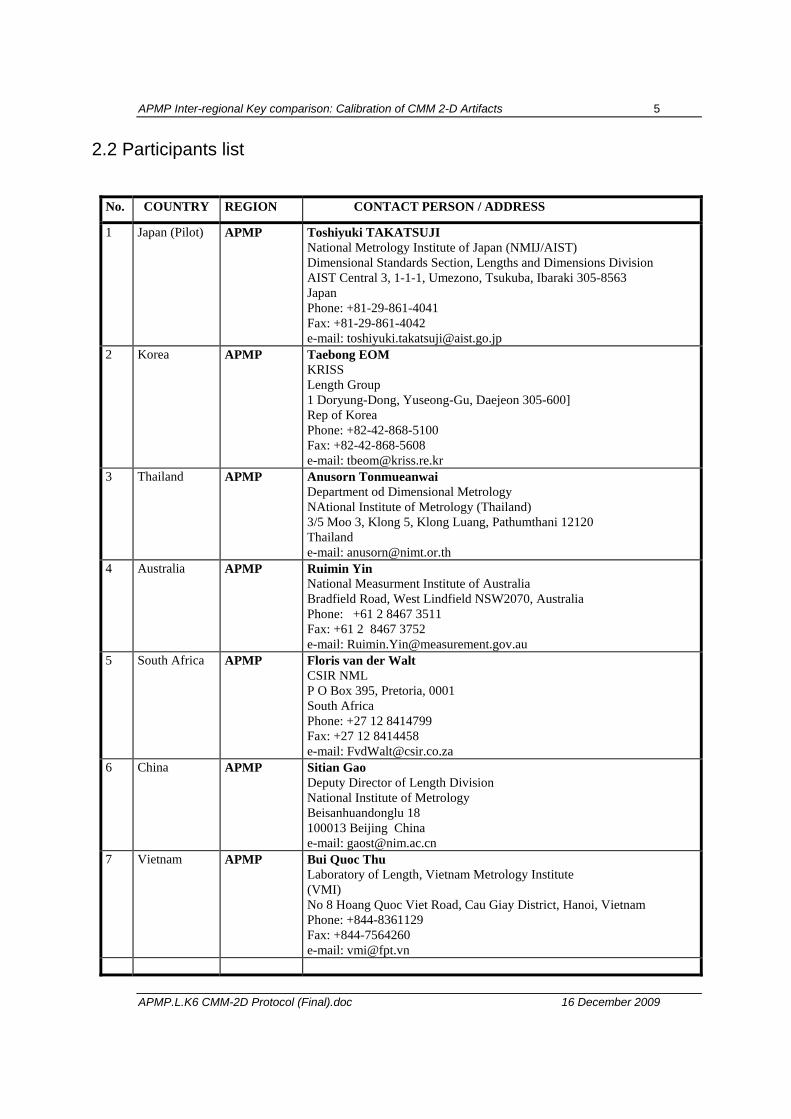
2.2 Participants list
No. COUNTRY REGION CONTACT PERSON / ADDRESS
1 Japan (Pilot) APMP Toshiyuki TAKATSUJI National Metrology Institute of Japan (NMIJ/AIST) Dimensional Standards Section, Lengths and Dimensions Division AIST Central 3, 1-1-1, Umezono, Tsukuba, Ibaraki 305-8563 Japan Phone: +81-29-861-4041 Fax: +81-29-861-4042 e-mail: [email protected]
2 Korea APMP Taebong EOM KRISS Length Group 1 Doryung-Dong, Yuseong-Gu, Daejeon 305-600] Rep of Korea Phone: +82-42-868-5100 Fax: +82-42-868-5608 e-mail: [email protected]
3 Thailand APMP Anusorn Tonmueanwai Department od Dimensional Metrology NAtional Institute of Metrology (Thailand) 3/5 Moo 3, Klong 5, Klong Luang, Pathumthani 12120 Thailand e-mail: [email protected]
4 Australia APMP Ruimin Yin National Measurment Institute of Australia Bradfield Road, West Lindfield NSW2070, Australia Phone: +61 2 8467 3511 Fax: +61 2 8467 3752 e-mail: [email protected]
5 South Africa APMP Floris van der Walt CSIR NML P O Box 395, Pretoria, 0001 South Africa Phone: +27 12 8414799 Fax: +27 12 8414458 e-mail: [email protected]
6 China APMP Sitian Gao Deputy Director of Length Division National Institute of Metrology Beisanhuandonglu 18 100013 Beijing China e-mail: [email protected]
7 Vietnam APMP Bui Quoc Thu Laboratory of Length, Vietnam Metrology Institute (VMI) No 8 Hoang Quoc Viet Road, Cau Giay District, Hanoi, Vietnam Phone: +844-8361129 Fax: +844-7564260 e-mail: [email protected]
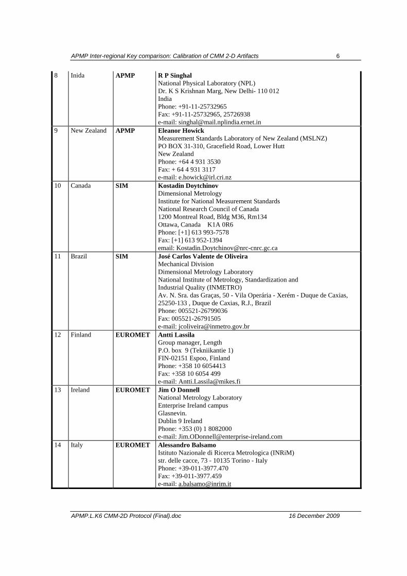
APMP Inter-regional Key comparison: Calibration of CMM 2-D Artifacts 6
APMP.L.K6 CMM-2D Protocol (Final).doc 16 December 2009
8 Inida APMP R P Singhal National Physical Laboratory (NPL) Dr. K S Krishnan Marg, New Delhi- 110 012 India Phone: +91-11-25732965 Fax: +91-11-25732965, 25726938 e-mail: [email protected]
9 New Zealand APMP Eleanor Howick Measurement Standards Laboratory of New Zealand (MSLNZ) PO BOX 31-310, Gracefield Road, Lower Hutt New Zealand Phone: +64 4 931 3530 Fax: + 64 4 931 3117 e-mail: [email protected]
10 Canada SIM Kostadin Doytchinov Dimensional Metrology Institute for National Measurement Standards National Research Council of Canada 1200 Montreal Road, Bldg M36, Rm134 Ottawa, Canada K1A 0R6 Phone: [+1] 613 993-7578 Fax: [+1] 613 952-1394 email: [email protected]
11 Brazil SIM José Carlos Valente de Oliveira Mechanical Division Dimensional Metrology Laboratory National Institute of Metrology, Standardization and Industrial Quality (INMETRO) Av. N. Sra. das Graças, 50 - Vila Operária - Xerém - Duque de Caxias, 25250-133 , Duque de Caxias, R.J., Brazil Phone: 005521-26799036 Fax: 005521-26791505 e-mail: [email protected]
12 Finland EUROMET Antti Lassila Group manager, Length P.O. box 9 (Tekniikantie 1) FIN-02151 Espoo, Finland Phone: +358 10 6054413 Fax: +358 10 6054 499 e-mail: [email protected]
13 Ireland EUROMET Jim O Donnell National Metrology Laboratory Enterprise Ireland campus Glasnevin. Dublin 9 Ireland Phone: +353 (0) 1 8082000 e-mail: [email protected]
14 Italy EUROMET Alessandro Balsamo Istituto Nazionale di Ricerca Metrologica (INRiM) str. delle cacce, 73 - 10135 Torino - Italy Phone: +39-011-3977.470 Fax: +39-011-3977.459 e-mail: [email protected]
APMP Inter-regional Key comparison: Calibration of CMM 2-D Artifacts 7
APMP.L.K6 CMM-2D Protocol (Final).doc 16 December 2009
2.3 Form of comparison 2.3.1 The calibration suitability of the artifacts has been assessed by measurements at NMIJ
prior to the start of the circulation of the artifacts. NMIJ will act as the pilot laboratory.
2.3.2 In the following section the timetable of the comparison is presented.
2.3.3 Each laboratory will receive the artifacts according to the pre-agreed timetable. Three loops will be carried out in succession. The first loop comprises of five APMP countries, and in all the countries an ATA carnet is acceptable. In the second loop, three APMP countries will participate, and no ATA carnet will be used in this loop. The third loop six countries from APMP, SIM, and EUROMET will participate, and an ATA carnet will be used except Brazil. At the beginning and the end of each loop, the gauges are sent to NMIJ/AIST (the pilot laboratory) for control measurements to check the stability of the gauges. Because of time constraints, it will not be possible to arrange for a ‘star-shaped’ circulation.
2.3.4 All results are to be communicated directly to the pilot laboratory as soon as possible and certainly within 4 weeks of completion of the measurements by each laboratory.
2.3.5 Each laboratory has one month for customs clearance, measurement and shipment to the following participant from the moment it is received at customs in his country till the following participant receives it at customs. With its confirmation to participate, each laboratory has confirmed that it is capable to perform the measurements in the time allocated to it. It guarantees that the standards arrive in the country of the next participant at the beginning of the next one month period.
2.3.5 If for some reasons, the measurement facility is not ready or customs clearance takes too much time in a country, the laboratory has to contact the pilot laboratory immediately and – according to the arrangement made – eventually to send the standards directly to the next participant before finishing the measurements or even without doing any measurements. Just in case this kind of situation happens, the next chance for the measurement will never be given. The participant is encouraged to participate in the next interregional key-comparison. The concept of interregional key-comparison wad invented to overcome this situation and to give opportunities for all NMIs to the maximum.
2.3.6 All participants shall strictly abide by the agreed time schedule. Being not able to complete the measurement by some reasons is not embarrassing as it is often the case with everyone. All participants, however, should keep it in mind that to delay the comparison will deteriorate your reputation.
APMP Inter-regional Key comparison: Calibration of CMM 2-D Artifacts 8
APMP.L.K6 CMM-2D Protocol (Final).doc 16 December 2009
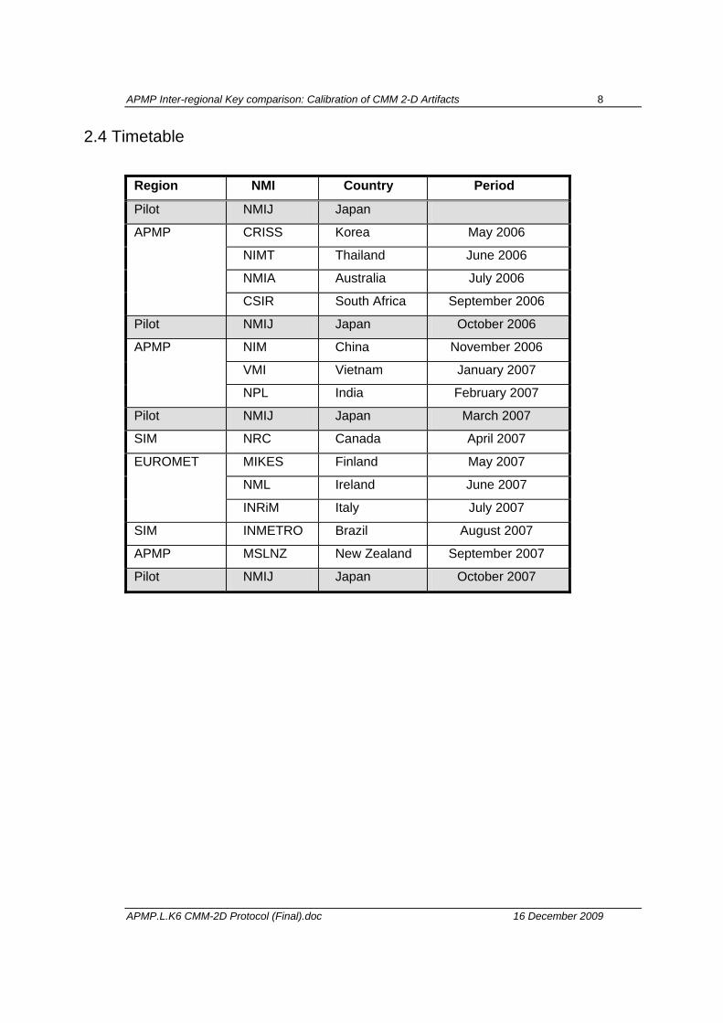
2.4 Timetable
Region NMI Country Period
Pilot NMIJ Japan
CRISS Korea May 2006
NIMT Thailand June 2006
NMIA Australia July 2006
APMP
CSIR South Africa September 2006
Pilot NMIJ Japan October 2006
NIM China November 2006
VMI Vietnam January 2007
APMP
NPL India February 2007
Pilot NMIJ Japan March 2007
SIM NRC Canada April 2007
MIKES Finland May 2007
NML Ireland June 2007
EUROMET
INRiM Italy July 2007
SIM INMETRO Brazil August 2007
APMP MSLNZ New Zealand September 2007
Pilot NMIJ Japan October 2007
APMP Inter-regional Key comparison: Calibration of CMM 2-D Artifacts 9
APMP.L.K6 CMM-2D Protocol (Final).doc 16 December 2009
2.5 Handling of Artifacts 2.5.1 Upon reception, the laboratory should confirm it to the pilot laboratory as well as to the
sender laboratory by sending the form of Appendix A1. The artifacts should be examined immediately upon receipt. The condition of the artifacts should also be noted in the form.
2.5.2 The artifacts should only be handled by authorized persons and stored in such a way as to prevent damage. The artifacts should not be touched with bare hands.
2.5.3 The artifacts should be examined before dispatch and any change in condition during the measurement at each laboratory should be communicated to the pilot laboratory.
2.5.4 Please inform the pilot laboratory and the next laboratory via fax or e-mail when the artifacts are about to be sent to the next recipient.
2.5.5 Before and after the measurements, the artifacts must be cleaned. Ensure that the content of the package is complete before shipment. Always use the original packaging.
2.5.6 The artifacts shouldn’t be lent to anyone other than the participants or used for any other purposes
2.5.7 The artifacts should be kept under 20 °C temperature and 50 % humidity condition as close as possible no matter if they are stored in the carriage container or not.
2.5.8 In order to monitor the temperature and humidity during the circulation, a small data logger is packed in the carriage box. The data logger should be placed near the gauges at all time, i.e. it should be taken out from the carriage box when the gauge is taken out. The recorded data is analyzed by the pilot after the whole comparison schedule is completed.
APMP Inter-regional Key comparison: Calibration of CMM 2-D Artifacts 10
APMP.L.K6 CMM-2D Protocol (Final).doc 16 December 2009
2.6 Transport of Artifacts 2.6.1 It is of utmost importance that the artifacts be transported in a manner in which they will
not be lost, damaged or handled by unauthorized persons.
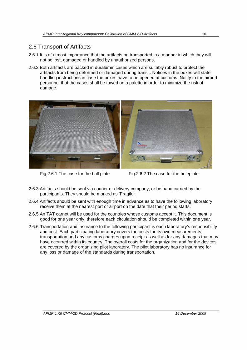
2.6.2 Both artifacts are packed in duralumin cases which are suitably robust to protect the artifacts from being deformed or damaged during transit. Notices in the boxes will state handling instructions in case the boxes have to be opened at customs. Notify to the airport personnel that the cases shall be towed on a palette in order to minimize the risk of damage.
Fig.2.6.1 The case for the ball plate Fig.2.6.2 The case for the holeplate
2.6.3 Artifacts should be sent via courier or delivery company, or be hand carried by the participants. They should be marked as ‘Fragile’.
2.6.4 Artifacts should be sent with enough time in advance as to have the following laboratory receive them at the nearest port or airport on the date that their period starts.
2.6.5 An TAT carnet will be used for the countries whose customs accept it. This document is good for one year only, therefore each circulation should be completed within one year.
2.6.6 Transportation and insurance to the following participant is each laboratory’s responsibility and cost. Each participating laboratory covers the costs for its own measurements, transportation and any customs charges upon receipt as well as for any damages that may have occurred within its country. The overall costs for the organization and for the devices are covered by the organizing pilot laboratory. The pilot laboratory has no insurance for any loss or damage of the standards during transportation.
APMP Inter-regional Key comparison: Calibration of CMM 2-D Artifacts 11
APMP.L.K6 CMM-2D Protocol (Final).doc 16 December 2009
3. Description of the Standards 3.1 Artifacts
The measurement artifacts are the following:
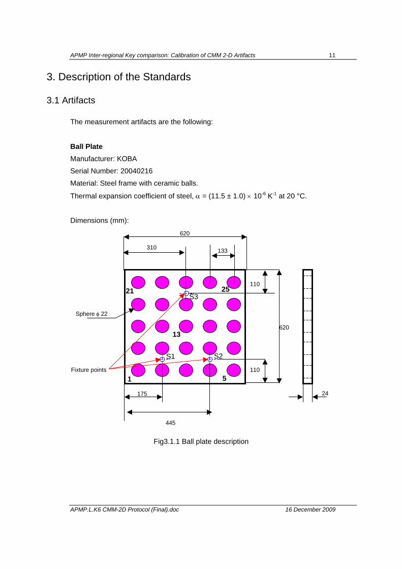
Ball Plate
Manufacturer: KOBA
Serial Number: 20040216
Material: Steel frame with ceramic balls.
Thermal expansion coefficient of steel, α = (11.5 ± 1.0) × 10-6 K-1 at 20 °C.
Dimensions (mm):
Fig3.1.1 Ball plate description
1 5
21 25
13620
620
110
175
445
310
110
Sphere φ 22
133
24
Fixture points
S1
S3
S2
APMP Inter-regional Key comparison: Calibration of CMM 2-D Artifacts 12
APMP.L.K6 CMM-2D Protocol (Final).doc 16 December 2009
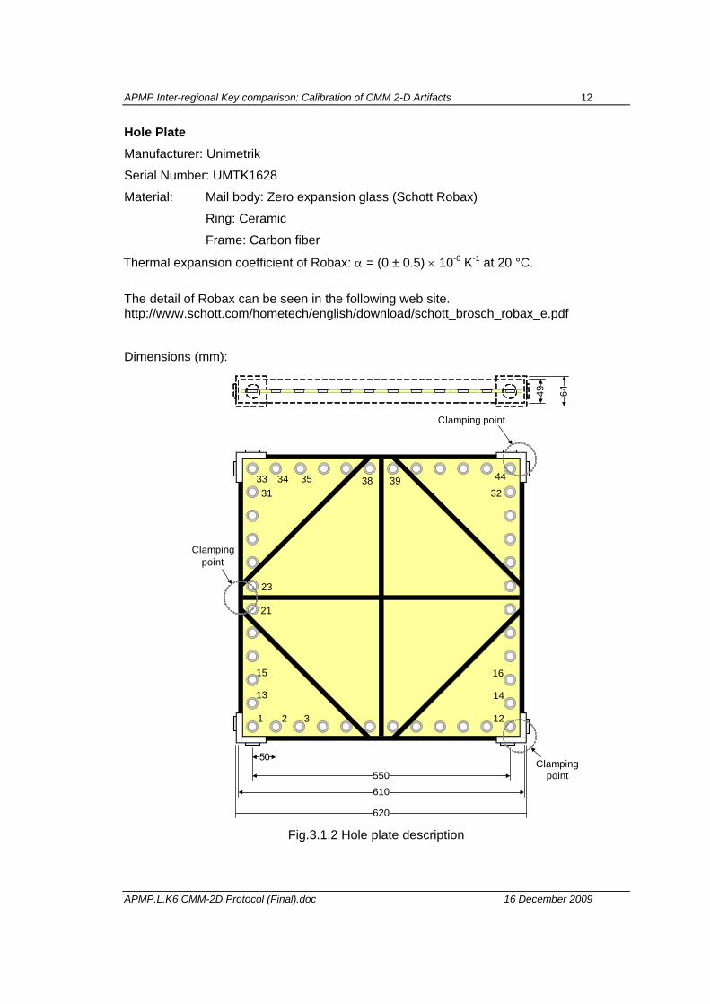
Hole Plate Manufacturer: Unimetrik
Serial Number: UMTK1628
Material: Mail body: Zero expansion glass (Schott Robax)
Ring: Ceramic
Frame: Carbon fiber
Thermal expansion coefficient of Robax: α = (0 ± 0.5) × 10-6 K-1 at 20 °C.
The detail of Robax can be seen in the following web site. http://www.schott.com/hometech/english/download/schott_brosch_robax_e.pdf
Dimensions (mm):
50
610550
620
49 64
Clampingpoint
Clamping point
1 2 3 12
34
14
32
16
13
35 4433
15
313938
Clampingpoint
21
23
Fig.3.1.2 Hole plate description
APMP Inter-regional Key comparison: Calibration of CMM 2-D Artifacts 13
APMP.L.K6 CMM-2D Protocol (Final).doc 16 December 2009
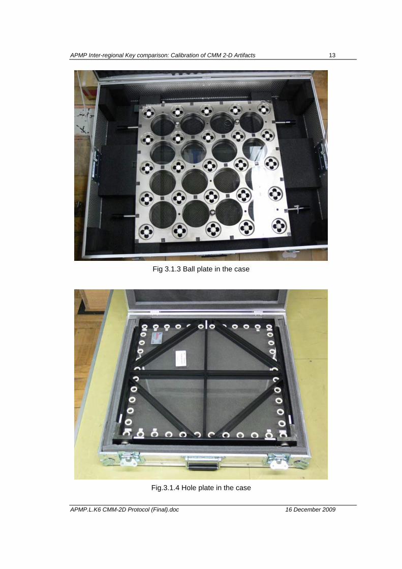
Fig 3.1.3 Ball plate in the case
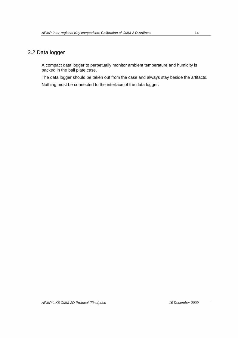
Fig.3.1.4 Hole plate in the case
APMP Inter-regional Key comparison: Calibration of CMM 2-D Artifacts 14
APMP.L.K6 CMM-2D Protocol (Final).doc 16 December 2009
3.2 Data logger
A compact data logger to perpetually monitor ambient temperature and humidity is packed in the ball plate case.
The data logger should be taken out from the case and always stay beside the artifacts.
Nothing must be connected to the interface of the data logger.
APMP Inter-regional Key comparison: Calibration of CMM 2-D Artifacts 15
APMP.L.K6 CMM-2D Protocol (Final).doc 16 December 2009
4. Measurement instructions
4.1 Traceability
4.1.1 Length measurements should be independently traceable to the latest realization of the mètre as set out in the current ”Mise en Pratique”. This means that the length unit is transferred to the ball and hole plates with the CMM by one of the following methods: laser interferometer, gauge blocks, ball beams, ball bar or step gauges. Whatever the instrument or standard used, it should be traceable to the definition of the length unit through calibrations performed in house. Temperature measurements should be made using the International Temperature Scale of 1990 (ITS-90).
4.2 Measurands
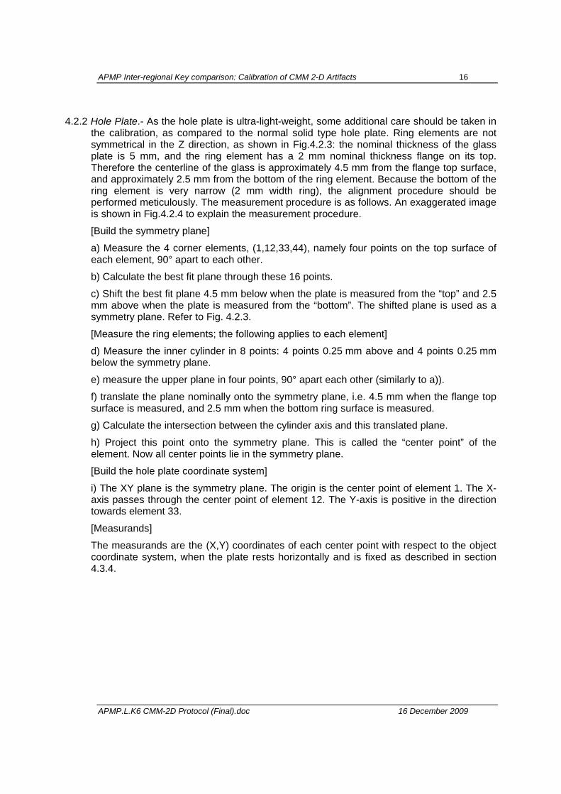
4.2.1 Ball Plate.- The object reference plane is defined by the center of balls number 1, 5 and 21. The origin of object coordinate system is the center of ball number 1. The X-axis of the object reference system is defined by the line that passes through the center of ball number 1 and the center of ball number 5. The direction from the origin to ball number 5 defines the positive X-axis direction. The Y-axis is defined as the orthogonal line that passes through the center of ball number 1. The positive direction is from ball number 1 to ball number 21. The measurands of the ball plate are the X and Y coordinates of each ball center with respect to the origin of object coordinate system (Fig.4.2.1) with the plate lying horizontally and fixed as described in section 4.3.3. It is recommended to report Z coordinates of each ball as well, however it is not in the scope of this comparison and will be used just as a reference.
Xobj
Yobj
Ball 1 (0,0,0) Ball 5 (x,0,0)
Ball 21 (x,y,0)
Figure 4.2.1. Ball plate coordinate system
1 5
21 25
13
APMP Inter-regional Key comparison: Calibration of CMM 2-D Artifacts 16
APMP.L.K6 CMM-2D Protocol (Final).doc 16 December 2009
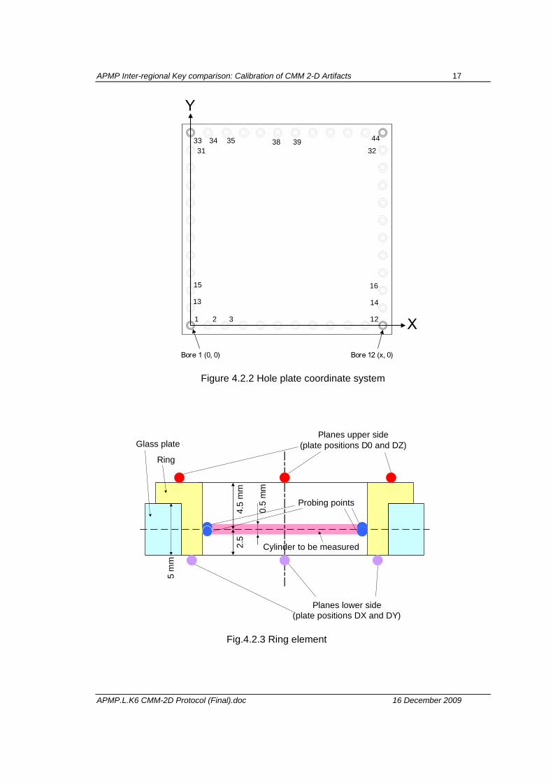
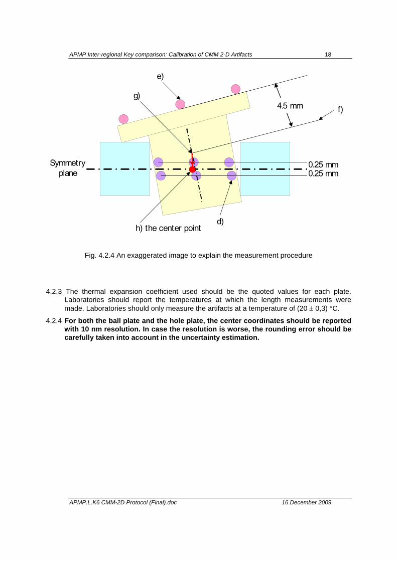
4.2.2 Hole Plate.- As the hole plate is ultra-light-weight, some additional care should be taken in the calibration, as compared to the normal solid type hole plate. Ring elements are not symmetrical in the Z direction, as shown in Fig.4.2.3: the nominal thickness of the glass plate is 5 mm, and the ring element has a 2 mm nominal thickness flange on its top. Therefore the centerline of the glass is approximately 4.5 mm from the flange top surface, and approximately 2.5 mm from the bottom of the ring element. Because the bottom of the ring element is very narrow (2 mm width ring), the alignment procedure should be performed meticulously. The measurement procedure is as follows. An exaggerated image is shown in Fig.4.2.4 to explain the measurement procedure.
[Build the symmetry plane]
a) Measure the 4 corner elements, (1,12,33,44), namely four points on the top surface of each element, 90° apart to each other.
b) Calculate the best fit plane through these 16 points.
c) Shift the best fit plane 4.5 mm below when the plate is measured from the “top” and 2.5 mm above when the plate is measured from the “bottom”. The shifted plane is used as a symmetry plane. Refer to Fig. 4.2.3.
[Measure the ring elements; the following applies to each element]
d) Measure the inner cylinder in 8 points: 4 points 0.25 mm above and 4 points 0.25 mm below the symmetry plane.
e) measure the upper plane in four points, 90° apart each other (similarly to a)).
f) translate the plane nominally onto the symmetry plane, i.e. 4.5 mm when the flange top surface is measured, and 2.5 mm when the bottom ring surface is measured.
g) Calculate the intersection between the cylinder axis and this translated plane.
h) Project this point onto the symmetry plane. This is called the “center point” of the element. Now all center points lie in the symmetry plane.
[Build the hole plate coordinate system]
i) The XY plane is the symmetry plane. The origin is the center point of element 1. The X-axis passes through the center point of element 12. The Y-axis is positive in the direction towards element 33.
[Measurands]
The measurands are the (X,Y) coordinates of each center point with respect to the object coordinate system, when the plate rests horizontally and is fixed as described in section 4.3.4.
APMP Inter-regional Key comparison: Calibration of CMM 2-D Artifacts 17
APMP.L.K6 CMM-2D Protocol (Final).doc 16 December 2009
1 2 3 12
34
14
32
16
13
35 4433
15
313938
X
Y
Bore 1 (0, 0) Bore 12 (x, 0)
Figure 4.2.2 Hole plate coordinate system
4.5
mm
2.5
5 m
m
Planes upper side(plate positions D0 and DZ)
Planes lower side(plate positions DX and DY)
Probing points
Cylinder to be measured
Ring
Glass plate
0.5
mm
Fig.4.2.3 Ring element
APMP Inter-regional Key comparison: Calibration of CMM 2-D Artifacts 18
APMP.L.K6 CMM-2D Protocol (Final).doc 16 December 2009
4.5 mm
d)
e)
f)g)
h) the center point
Symmetryplane
0.25 mm0.25 mm
Fig. 4.2.4 An exaggerated image to explain the measurement procedure
4.2.3 The thermal expansion coefficient used should be the quoted values for each plate. Laboratories should report the temperatures at which the length measurements were made. Laboratories should only measure the artifacts at a temperature of (20 ± 0,3) °C.
4.2.4 For both the ball plate and the hole plate, the center coordinates should be reported with 10 nm resolution. In case the resolution is worse, the rounding error should be carefully taken into account in the uncertainty estimation.
APMP Inter-regional Key comparison: Calibration of CMM 2-D Artifacts 19
APMP.L.K6 CMM-2D Protocol (Final).doc 16 December 2009
4.3. Measurement instructions 4.3.1 Each laboratory is free to use his own measuring method. However, measurements should
be reported in the object reference coordinate system described in 4.2. Appendix A5 describes one measurement method that can be used. Before measurement, the artifacts must be inspected for damage. Special attention should be paid to the measurement surfaces and form elements (balls or holes). Any scratches rusty spots or other damages have to be documented. Appendix A1 contains a form that should be filled and sent upon reception quoting the state of the artifacts as received.
4.3.2 Before measurement, the plates and supports must be cleaned. The form elements have to be cleaned with special care individually as well as the measuring surfaces in the vicinity of all probing points.
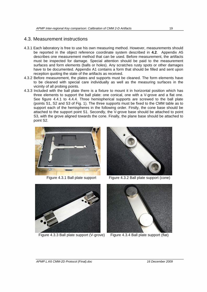
4.3.3 Included with the ball plate there is a fixture to mount it in horizontal position which has three elements to support the ball plate: one conical, one with a V-grove and a flat one. See figure 4.4.1 to 4.4.4. Three hemispherical supports are screwed to the ball plate (points S1, S2 and S3 of Fig. 1). The three supports must be fixed to the CMM table as to support each of the hemispheres in the following order. Firstly, the cone base should be attached to the support point S1. Secondly, the V-grove base should be attached to point S3, with the grove aligned towards the cone. Finally, the plane base should be attached to point S2.
Figure 4.3.1 Ball plate support Figure 4.3.2 Ball plate support (cone)
Figure 4.3.3 Ball plate support (V-grove) Figure 4.3.4 Ball plate support (flat)
APMP Inter-regional Key comparison: Calibration of CMM 2-D Artifacts 20
APMP.L.K6 CMM-2D Protocol (Final).doc 16 December 2009
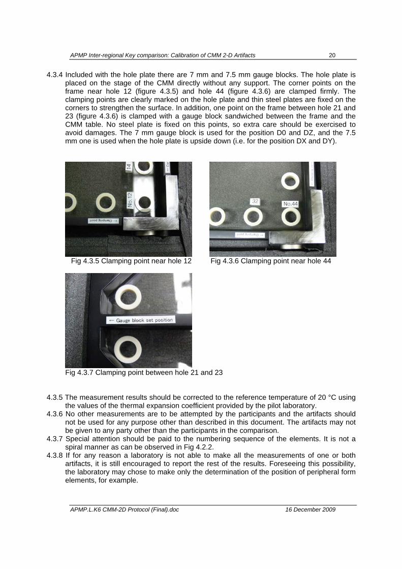
4.3.4 Included with the hole plate there are 7 mm and 7.5 mm gauge blocks. The hole plate is placed on the stage of the CMM directly without any support. The corner points on the frame near hole 12 (figure 4.3.5) and hole 44 (figure 4.3.6) are clamped firmly. The clamping points are clearly marked on the hole plate and thin steel plates are fixed on the corners to strengthen the surface. In addition, one point on the frame between hole 21 and 23 (figure 4.3.6) is clamped with a gauge block sandwiched between the frame and the CMM table. No steel plate is fixed on this points, so extra care should be exercised to avoid damages. The 7 mm gauge block is used for the position D0 and DZ, and the 7.5 mm one is used when the hole plate is upside down (i.e. for the position DX and DY).
Fig 4.3.5 Clamping point near hole 12 Fig 4.3.6 Clamping point near hole 44
Fig 4.3.7 Clamping point between hole 21 and 23
4.3.5 The measurement results should be corrected to the reference temperature of 20 °C using
the values of the thermal expansion coefficient provided by the pilot laboratory. 4.3.6 No other measurements are to be attempted by the participants and the artifacts should
not be used for any purpose other than described in this document. The artifacts may not be given to any party other than the participants in the comparison.
4.3.7 Special attention should be paid to the numbering sequence of the elements. It is not a spiral manner as can be observed in Fig 4.2.2.
4.3.8 If for any reason a laboratory is not able to make all the measurements of one or both artifacts, it is still encouraged to report the rest of the results. Foreseeing this possibility, the laboratory may chose to make only the determination of the position of peripheral form elements, for example.
APMP Inter-regional Key comparison: Calibration of CMM 2-D Artifacts 21
APMP.L.K6 CMM-2D Protocol (Final).doc 16 December 2009
5. Measurement uncertainty
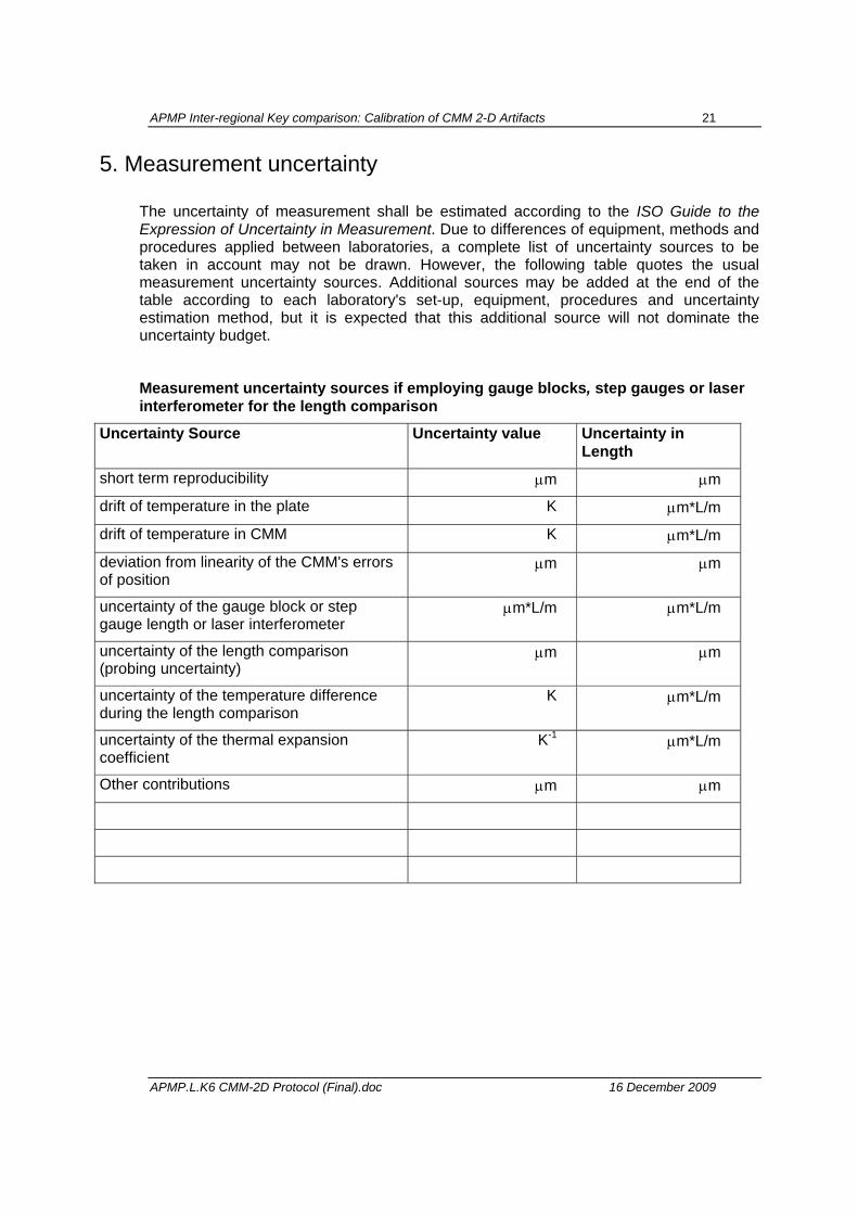
The uncertainty of measurement shall be estimated according to the ISO Guide to the Expression of Uncertainty in Measurement. Due to differences of equipment, methods and procedures applied between laboratories, a complete list of uncertainty sources to be taken in account may not be drawn. However, the following table quotes the usual measurement uncertainty sources. Additional sources may be added at the end of the table according to each laboratory's set-up, equipment, procedures and uncertainty estimation method, but it is expected that this additional source will not dominate the uncertainty budget.
Measurement uncertainty sources if employing gauge blocks, step gauges or laser interferometer for the length comparison
Uncertainty Source Uncertainty value Uncertainty in Length
short term reproducibility µm µm
drift of temperature in the plate K µm*L/m
drift of temperature in CMM K µm*L/m
deviation from linearity of the CMM's errors of position
µm µm
uncertainty of the gauge block or step gauge length or laser interferometer
µm*L/m µm*L/m
uncertainty of the length comparison (probing uncertainty)
µm µm
uncertainty of the temperature difference during the length comparison
K µm*L/m
uncertainty of the thermal expansion coefficient
K-1 µm*L/m
Other contributions µm µm
APMP Inter-regional Key comparison: Calibration of CMM 2-D Artifacts 22
APMP.L.K6 CMM-2D Protocol (Final).doc 16 December 2009
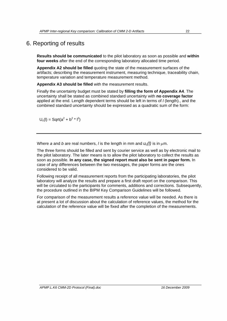
6. Reporting of results
Results should be communicated to the pilot laboratory as soon as possible and within four weeks after the end of the corresponding laboratory allocated time period.
Appendix A2 should be filled quoting the state of the measurement surfaces of the artifacts; describing the measurement instrument, measuring technique, traceability chain, temperature variation and temperature measurement method.
Appendix A3 should be filled with the measurement results.
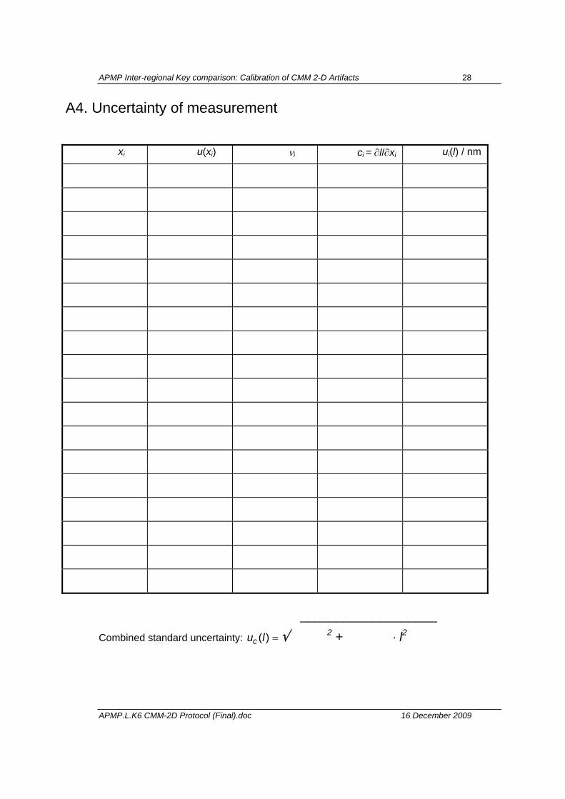
Finally the uncertainty budget must be stated by filling the form of Appendix A4. The uncertainty shall be stated as combined standard uncertainty with no coverage factor applied at the end. Length dependent terms should be left in terms of l (length)., and the combined standard uncertainty should be expressed as a quadratic sum of the form:
Uc(l) = Sqrt(a2 + b2 * l2)
Where a and b are real numbers, l is the length in mm and uc(l) is in µm. The three forms should be filled and sent by courier service as well as by electronic mail to the pilot laboratory. The later means is to allow the pilot laboratory to collect the results as soon as possible. In any case, the signed report must also be sent in paper form. In case of any differences between the two messages, the paper forms are the ones considered to be valid.
Following receipt of all measurement reports from the participating laboratories, the pilot laboratory will analyze the results and prepare a first draft report on the comparison. This will be circulated to the participants for comments, additions and corrections. Subsequently, the procedure outlined in the BIPM Key Comparison Guidelines will be followed.
For comparison of the measurement results a reference value will be needed. As there is at present a lot of discussion about the calculation of reference values, the method for the calculation of the reference value will be fixed after the completion of the measurements.
APMP Inter-regional Key comparison: Calibration of CMM 2-D Artifacts 23
APMP.L.K6 CMM-2D Protocol (Final).doc 16 December 2009
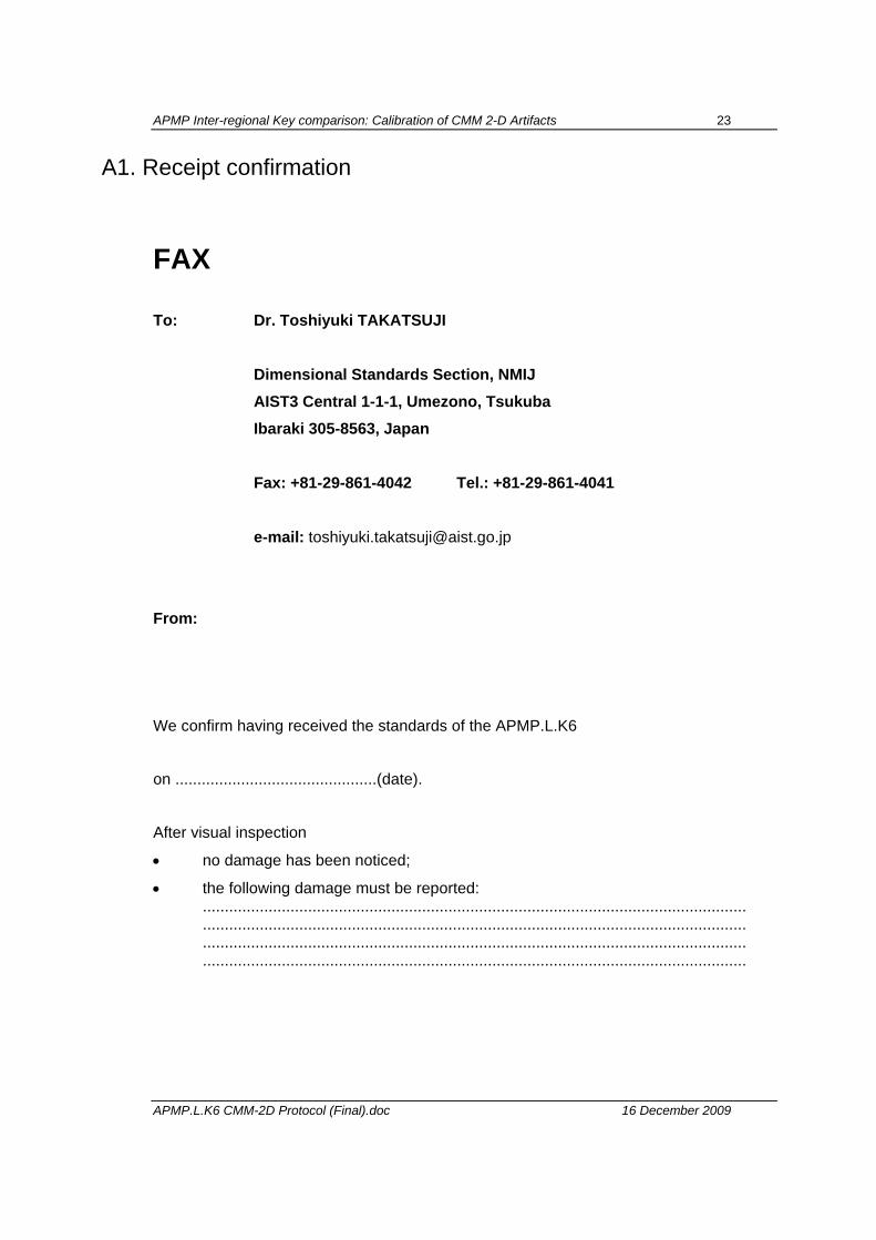
A1. Receipt confirmation
FAX To: Dr. Toshiyuki TAKATSUJI Dimensional Standards Section, NMIJ AIST3 Central 1-1-1, Umezono, Tsukuba Ibaraki 305-8563, Japan Fax: +81-29-861-4042 Tel.: +81-29-861-4041 e-mail: [email protected] From:
We confirm having received the standards of the APMP.L.K6
on ..............................................(date).
After visual inspection
• no damage has been noticed;
• the following damage must be reported: ............................................................................................................................ ............................................................................................................................ ............................................................................................................................ ............................................................................................................................
APMP Inter-regional Key comparison: Calibration of CMM 2-D Artifacts 24
APMP.L.K6 CMM-2D Protocol (Final).doc 16 December 2009
A2. Report of measurement A2.1 Inspection of the measurement surfaces
Notes:
APMP Inter-regional Key comparison: Calibration of CMM 2-D Artifacts 25
APMP.L.K6 CMM-2D Protocol (Final).doc 16 December 2009
A2.2 Description of the measurement instrument
Manufacturer and type of instrument
(If you use a non-commercial or significant modified commercial equipment, please add drawings, explaining papers etc.)
Traceability path (gauge blocks, step gauge, laser interferometer.):
Description of measuring technique:
Range of artifact temperature during measurements & description of temperature measurement method:
APMP Inter-regional Key comparison: Calibration of CMM 2-D Artifacts 26
APMP.L.K6 CMM-2D Protocol (Final).doc 16 December 2009
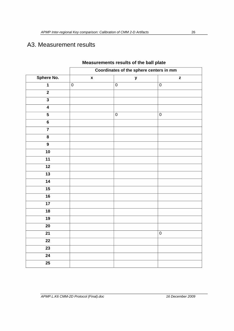
A3. Measurement results
Measurements results of the ball plate Coordinates of the sphere centers in mm
Sphere No. x y z
1 0 0 0
2
3
4
5 0 0
6
7
8
9
10
11
12
13
14
15
16
17
18
19
20
21 0
22
23
24
25
APMP Inter-regional Key comparison: Calibration of CMM 2-D Artifacts 27
APMP.L.K6 CMM-2D Protocol (Final).doc 16 December 2009
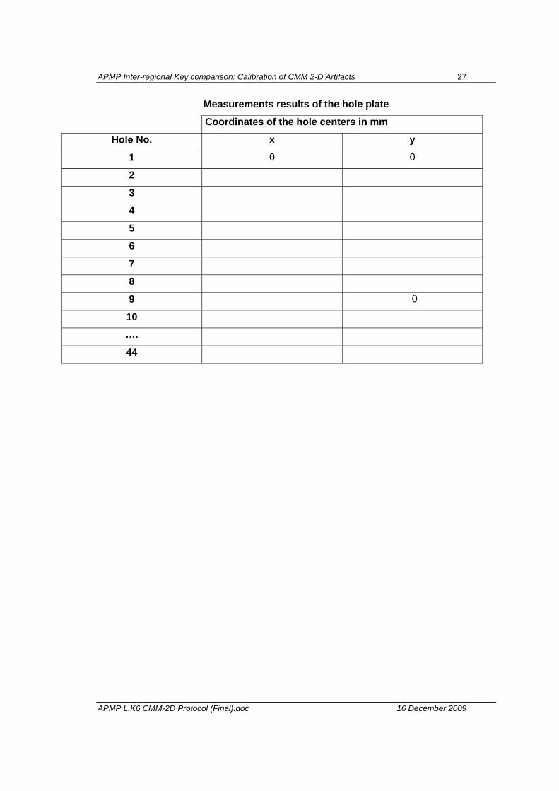
Measurements results of the hole plate
Coordinates of the hole centers in mm
Hole No. x y
1 0 0
2
3
4
5
6
7
8
9 0
10
….
44
APMP Inter-regional Key comparison: Calibration of CMM 2-D Artifacts 28
APMP.L.K6 CMM-2D Protocol (Final).doc 16 December 2009
A4. Uncertainty of measurement
xi u(xi) νi ci = ∂l/∂xi ui(l) / nm
___________________ Combined standard uncertainty: u lc ( ) = √ 2 + ⋅ l2
APMP Inter-regional Key comparison: Calibration of CMM 2-D Artifacts 29
APMP.L.K6 CMM-2D Protocol (Final).doc 16 December 2009
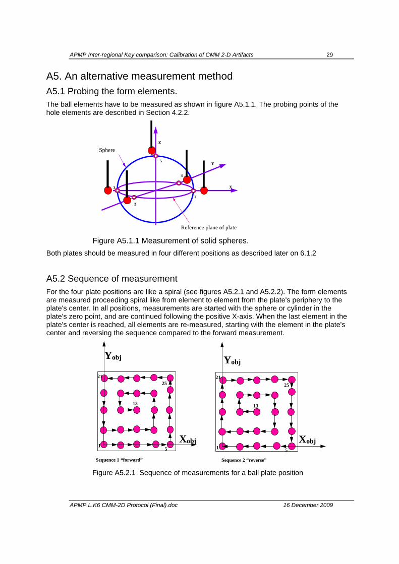
A5. An alternative measurement method A5.1 Probing the form elements. The ball elements have to be measured as shown in figure A5.1.1. The probing points of the hole elements are described in Section 4.2.2.
Sphere
3
2
1
5
4
Z
Y
X
Reference plane of plate Figure A5.1.1 Measurement of solid spheres.
Both plates should be measured in four different positions as described later on 6.1.2
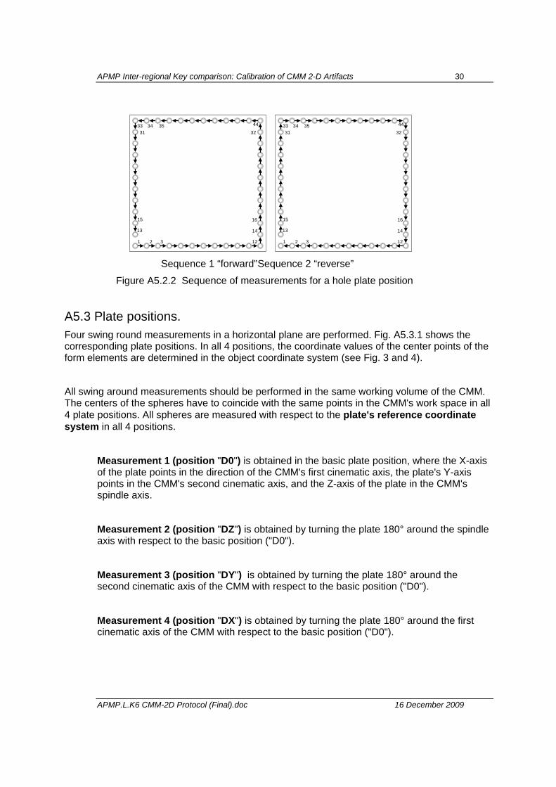
A5.2 Sequence of measurement For the four plate positions are like a spiral (see figures A5.2.1 and A5.2.2). The form elements are measured proceeding spiral like from element to element from the plate's periphery to the plate's center. In all positions, measurements are started with the sphere or cylinder in the plate's zero point, and are continued following the positive X-axis. When the last element in the plate's center is reached, all elements are re-measured, starting with the element in the plate's center and reversing the sequence compared to the forward measurement.
Sequence 1 “forward” Sequence 2 “reverse”
15
2125
Xobj
Yobj
13
51
2125
Yobj
Xobj
13
Figure A5.2.1 Sequence of measurements for a ball plate position
APMP Inter-regional Key comparison: Calibration of CMM 2-D Artifacts 30
APMP.L.K6 CMM-2D Protocol (Final).doc 16 December 2009
1 2 3 12
34
14
32
16
13
35 4433
15
31
1 2 3 12
34
14
32
16
13
35 4433
15
31
Sequence 1 “forward” Sequence 2 “reverse”
Figure A5.2.2 Sequence of measurements for a hole plate position
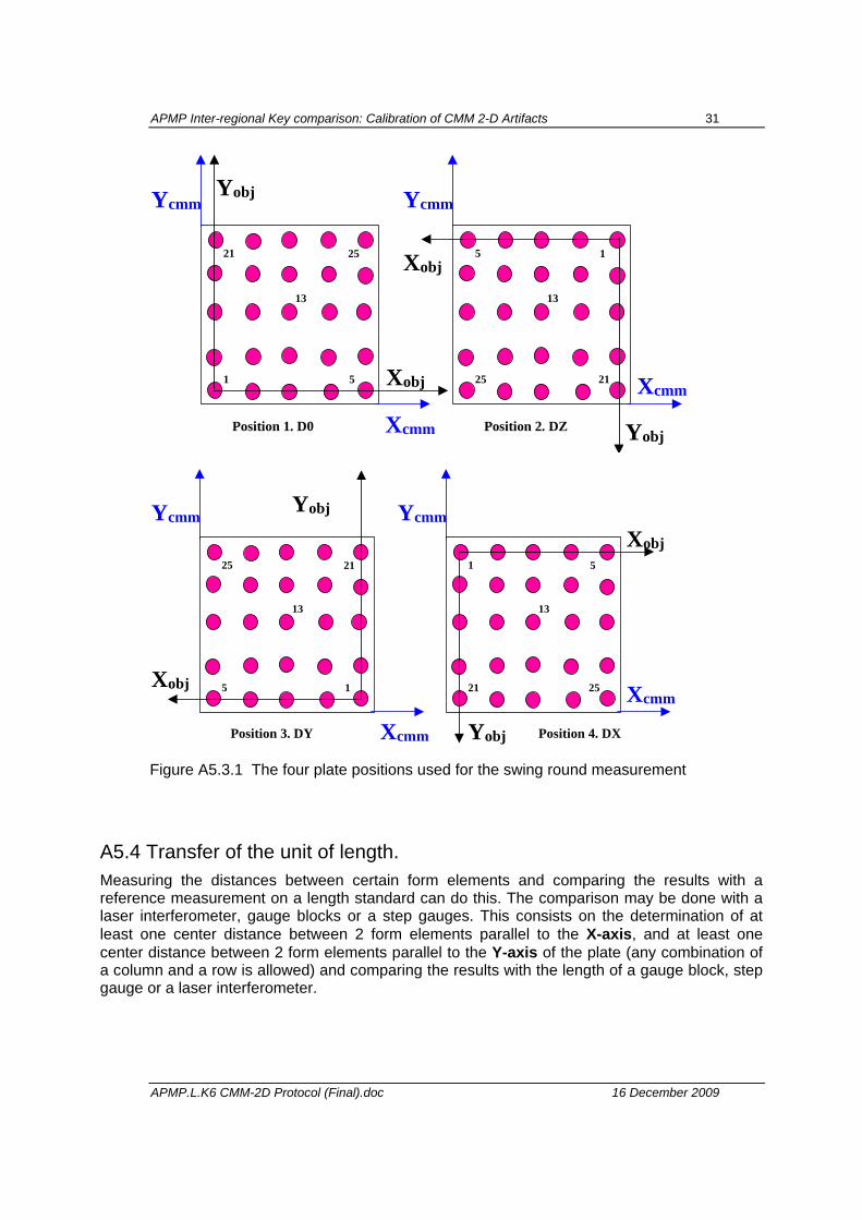
A5.3 Plate positions. Four swing round measurements in a horizontal plane are performed. Fig. A5.3.1 shows the corresponding plate positions. In all 4 positions, the coordinate values of the center points of the form elements are determined in the object coordinate system (see Fig. 3 and 4).
All swing around measurements should be performed in the same working volume of the CMM. The centers of the spheres have to coincide with the same points in the CMM's work space in all 4 plate positions. All spheres are measured with respect to the plate's reference coordinate system in all 4 positions.
Measurement 1 (position "D0") is obtained in the basic plate position, where the X-axis of the plate points in the direction of the CMM's first cinematic axis, the plate's Y-axis points in the CMM's second cinematic axis, and the Z-axis of the plate in the CMM's spindle axis.
Measurement 2 (position "DZ") is obtained by turning the plate 180° around the spindle axis with respect to the basic position ("D0").
Measurement 3 (position "DY") is obtained by turning the plate 180° around the second cinematic axis of the CMM with respect to the basic position ("D0").
Measurement 4 (position "DX") is obtained by turning the plate 180° around the first cinematic axis of the CMM with respect to the basic position ("D0").
APMP Inter-regional Key comparison: Calibration of CMM 2-D Artifacts 31
APMP.L.K6 CMM-2D Protocol (Final).doc 16 December 2009
Position 1. D0
Xobj
Yobj
1 5
21 25
13
Xcmm
Ycmm
Position 2. DZ
Xobj
Yobj
25 21
5 1
13
Xcmm
Ycmm
Position 3. DY
Xobj
Yobj
5 1
25 21
13
Xcmm
Ycmm
Position 4. DX
Xobj
Yobj
21 25
1 5
13
Xcmm
Ycmm
Figure A5.3.1 The four plate positions used for the swing round measurement
A5.4 Transfer of the unit of length. Measuring the distances between certain form elements and comparing the results with a reference measurement on a length standard can do this. The comparison may be done with a laser interferometer, gauge blocks or a step gauges. This consists on the determination of at least one center distance between 2 form elements parallel to the X-axis, and at least one center distance between 2 form elements parallel to the Y-axis of the plate (any combination of a column and a row is allowed) and comparing the results with the length of a gauge block, step gauge or a laser interferometer.