intel galileo - jameco electronics · intel galileo intel galileo front intel galileo back overview...
TRANSCRIPT

Intel Galileo
Intel Galileo Front Intel Galileo Back
Overview
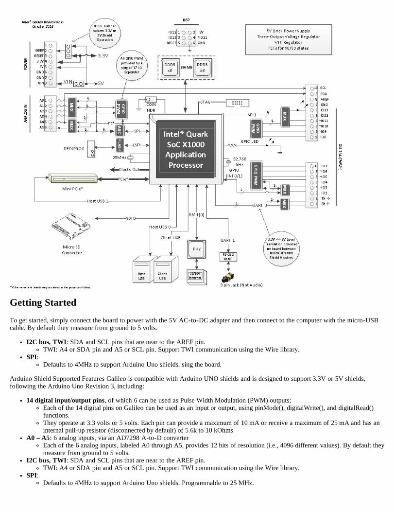
Galileo is a microcontroller board based on the Intel® Quark SoC X1000 Application Processor, a 32-bit Intel Pentium-class system on achip (datasheet). It’s the first board based on Intel® architecture designed to be hardware and software pin-compatible with Arduinoshields designed for the Uno R3. Digital pins 0 to 13 (and the adjacent AREF and GND pins), Analog inputs 0 to 5, the power header,ICSP header, and the UART port pins (0 and 1), are all in the same locations as on the Arduino Uno R3. This is also known as theArduino 1.0 pinout.
Galileo is designed to support shields that operate at either 3.3V or 5V. The core operating voltage of Galileo is 3.3V. However, a jumperon the board enables voltage translation to 5V at the I/O pins. This provides support for 5V Uno shields and is the default behavior. Byswitching the jumper position, the voltage translation can be disabled to provide 3.3V operation at the I/O pins.
Of course, the Galileo board is also software compatible with the Arduino Software Development Environment (IDE), which makesusability and introduction a snap. In addition to Arduino hardware and software compatibility, the Galileo board has several PC industrystandard I/O ports and features to expand native usage and capabilities beyond the Arduino shield ecosystem. A full sized mini-PCIExpress slot, 100Mb Ethernet port, Micro-SD slot, RS-232 serial port, USB Host port, USB Client port, and 8MByte NOR flash comestandard on the board.
Visit the FAQ page for further informations.
Getting Started
To get started, simply connect the board to power with the 5V AC-to-DC adapter and then connect to the computer with the micro-USBcable. By default they measure from ground to 5 volts.
I2C bus, TWI: SDA and SCL pins that are near to the AREF pin.TWI: A4 or SDA pin and A5 or SCL pin. Support TWI communication using the Wire library.
SPI:Defaults to 4MHz to support Arduino Uno shields. sing the board.
Arduino Shield Supported Features Galileo is compatible with Arduino UNO shields and is designed to support 3.3V or 5V shields,following the Arduino Uno Revision 3, including:
14 digital input/output pins, of which 6 can be used as Pulse Width Modulation (PWM) outputs;Each of the 14 digital pins on Galileo can be used as an input or output, using pinMode(), digitalWrite(), and digitalRead()functions.They operate at 3.3 volts or 5 volts. Each pin can provide a maximum of 10 mA or receive a maximum of 25 mA and has aninternal pull-up resistor (disconnected by default) of 5.6k to 10 kOhms.
A0 – A5: 6 analog inputs, via an AD7298 A-to-D converterEach of the 6 analog inputs, labeled A0 through A5, provides 12 bits of resolution (i.e., 4096 different values). By default theymeasure from ground to 5 volts.
I2C bus, TWI: SDA and SCL pins that are near to the AREF pin.TWI: A4 or SDA pin and A5 or SCL pin. Support TWI communication using the Wire library.
SPI:Defaults to 4MHz to support Arduino Uno shields. Programmable to 25 MHz.

Note: While Galileo has a native SPI controller, it will act as a master and not as an SPI slave. Therefore, Galileo cannot be aSPI slave to another SPI master. It can act, however, as a slave device via the USB Client connector.
UART (serial port): Programmable speed UART port (digital pins 0 (RX) and 1 (TX))ICSP (SPI): a 6 pin in-circuit serial programming (ICSP) header, located appropriately to plug into existing shields. These pinssupport SPI communication using the SPI library.VIN: The input voltage to the Galileo board when it's using an external power source (as opposed to 5 volts from the regulatedpower supply connected at the power jack). You can supply voltage through this pin, or, if supplying voltage via the power jack,access it through this pin.
Warning: The voltage applied to this pin must be a regulated 5V supply otherwise it could damage the Galileo board or causeincorrect operation.
5V output pin: This pin outputs 5V from the external source or the USB connector. Maximum current draw to the shield is: 800mA3.3V output pin: A 3.3 volt supply generated by the on-board regulator. Maximum current draw to the shield is: 800 mAGND: Ground pins.IOREF: The IOREF pin on Galileo allows an attached shield with the proper configuration to adapt to the voltage provided by theboard. The IOREF pin voltage is controlled by a jumper on the board, i.e., a selection jumper on the board is used to select between3.3V and 5V shield operation.RESET button/pin: Bring this line LOW to reset the sketch. Typically used to add a reset button to shields that block the one onthe board.AREF is unused on Galileo. Providing an external reference voltage for the analog inputs is not supported.
For Galileo it is not possible to change the upper end of the analog input range using the AREF pin and the analogReference()function.
Check out the Audio Sample Sequencer tutorial of the project that Arduino Verkstad brought at the Maker Faire Rome at the Intel GalileoBooth.
Details of Intel Architecture Supported Features
The genuine Intel processor and surrounding native I/O capabilities of the Clanton SoC provides for a fully featured offering for both themaker community and students alike. It will also be useful to professional developers who are looking for a simple and cost effectivedevelopment environment to the more complex Intel® Atom processor and Intel® Core processor-based designs.
400MHz 32-bit Intel® Pentium instruction set architecture (ISA)-compatible processor o 16 KBytes on-die L1 cache512 KBytes of on-die embedded SRAMSimple to program: Single thread, single core, constant speedACPI compatible CPU sleep states supportedAn integrated Real Time Clock (RTC), with an optional 3V “coin cell” battery for operation between turn on cycles.
10/100 Ethernet connectorFull PCI Express* mini-card slot, with PCIe 2.0 compliant features
Works with half mini-PCIe cards with optional converter plateProvides USB 2.0 Host Port at mini-PCIe connector
USB 2.0 Host connectorSupport up to 128 USB end point devices
USB Device connector, used for programmingBeyond just a programming port - a fully compliant USB 2.0 Device controller
10-pin Standard JTAG header for debuggingReboot button to reboot the processorReset button to reset the sketch and any attached shieldsStorage options:
Default - 8 MByte Legacy SPI Flash main purpose is to store the firmware (or bootloader) and the latest sketch. Between256KByte and 512KByte is dedicated for sketch storage. The download will happen automatically from the development PC,so no action is required unless there is an upgrade that is being added to the firmware.Default 512 KByte embedded SRAM, enabled by the firmware by default. No action required to use this feature.Default 256 MByte DRAM, enabled by the firmware by default.Optional micro SD card offers up to 32GByte of storageUSB storage works with any USB 2.0 compatible drive11 KByte EEPROM can be programmed via the EEPROM library.
Schematic, Reference Design & Pin Mapping
Schematics: GalileoSchematic.pdfCadence® Allegro® Files: GalileoReferenceDesign.zip
Power
Galileo is powered via an AC-to-DC adapter, connected by plugging a 2.1mm center-positive plug into the board's power jack. Therecommended output rating of the power adapter is 5V at up to 3Amp.
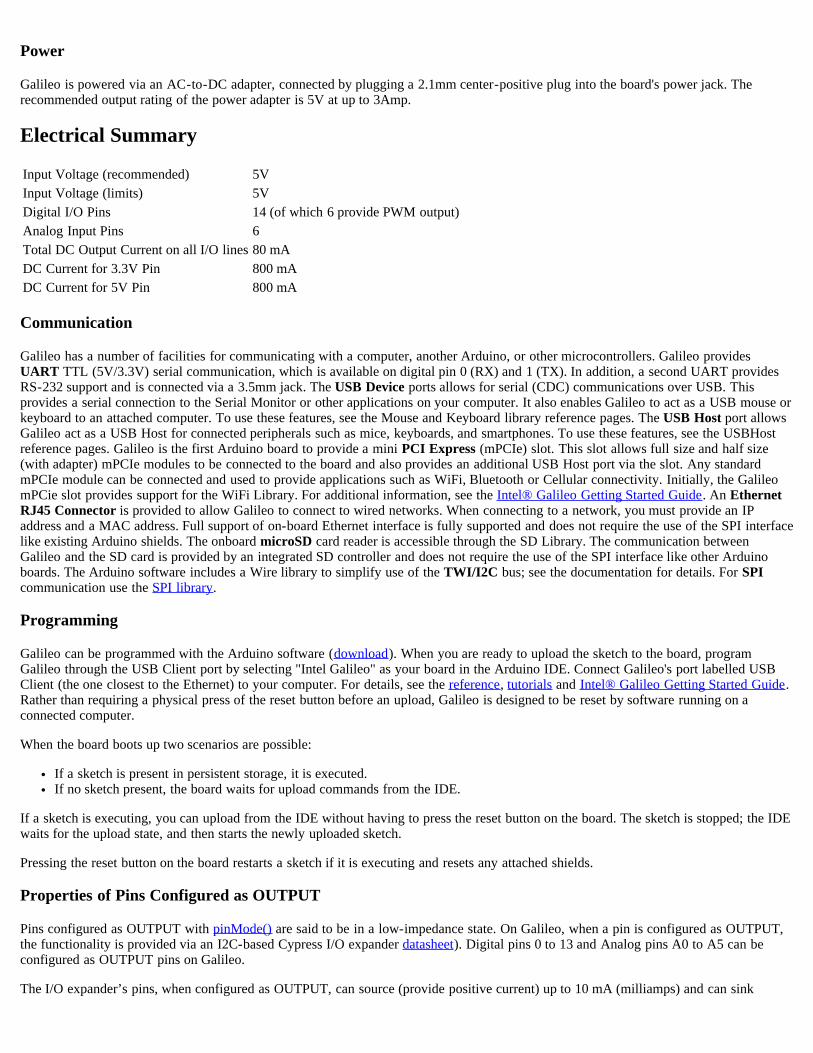
Electrical Summary
Input Voltage (recommended) 5VInput Voltage (limits) 5VDigital I/O Pins 14 (of which 6 provide PWM output)Analog Input Pins 6Total DC Output Current on all I/O lines 80 mADC Current for 3.3V Pin 800 mADC Current for 5V Pin 800 mA
Communication
Galileo has a number of facilities for communicating with a computer, another Arduino, or other microcontrollers. Galileo providesUART TTL (5V/3.3V) serial communication, which is available on digital pin 0 (RX) and 1 (TX). In addition, a second UART providesRS-232 support and is connected via a 3.5mm jack. The USB Device ports allows for serial (CDC) communications over USB. Thisprovides a serial connection to the Serial Monitor or other applications on your computer. It also enables Galileo to act as a USB mouse orkeyboard to an attached computer. To use these features, see the Mouse and Keyboard library reference pages. The USB Host port allowsGalileo act as a USB Host for connected peripherals such as mice, keyboards, and smartphones. To use these features, see the USBHostreference pages. Galileo is the first Arduino board to provide a mini PCI Express (mPCIe) slot. This slot allows full size and half size(with adapter) mPCIe modules to be connected to the board and also provides an additional USB Host port via the slot. Any standardmPCIe module can be connected and used to provide applications such as WiFi, Bluetooth or Cellular connectivity. Initially, the GalileomPCie slot provides support for the WiFi Library. For additional information, see the Intel® Galileo Getting Started Guide. An EthernetRJ45 Connector is provided to allow Galileo to connect to wired networks. When connecting to a network, you must provide an IPaddress and a MAC address. Full support of on-board Ethernet interface is fully supported and does not require the use of the SPI interfacelike existing Arduino shields. The onboard microSD card reader is accessible through the SD Library. The communication betweenGalileo and the SD card is provided by an integrated SD controller and does not require the use of the SPI interface like other Arduinoboards. The Arduino software includes a Wire library to simplify use of the TWI/I2C bus; see the documentation for details. For SPIcommunication use the SPI library.
Programming
Galileo can be programmed with the Arduino software (download). When you are ready to upload the sketch to the board, programGalileo through the USB Client port by selecting "Intel Galileo" as your board in the Arduino IDE. Connect Galileo's port labelled USBClient (the one closest to the Ethernet) to your computer. For details, see the reference, tutorials and Intel® Galileo Getting Started Guide.Rather than requiring a physical press of the reset button before an upload, Galileo is designed to be reset by software running on aconnected computer.
When the board boots up two scenarios are possible:
If a sketch is present in persistent storage, it is executed.If no sketch present, the board waits for upload commands from the IDE.
If a sketch is executing, you can upload from the IDE without having to press the reset button on the board. The sketch is stopped; the IDEwaits for the upload state, and then starts the newly uploaded sketch.
Pressing the reset button on the board restarts a sketch if it is executing and resets any attached shields.
Properties of Pins Configured as OUTPUT
Pins configured as OUTPUT with pinMode() are said to be in a low-impedance state. On Galileo, when a pin is configured as OUTPUT,the functionality is provided via an I2C-based Cypress I/O expander datasheet). Digital pins 0 to 13 and Analog pins A0 to A5 can beconfigured as OUTPUT pins on Galileo.
The I/O expander’s pins, when configured as OUTPUT, can source (provide positive current) up to 10 mA (milliamps) and can sink
(provide negative current) up to 25 mA of current to other devices/circuits. The individual per pin current sourcing capability of 10 mA issubject to an overall limit of 80 mA combined between all OUTPUT pins. The per pin capability current sinking capability is subject to anoverall limit of 200 mA. The following table provides a breakdown of the overall OUTPUT capabilities of the pins.
Current Source (mA) Current Sink (mA)Per Pin Capability 10 25Digital Pins 3,5,9,10,12, 13 Combined 40 100Digital Pins 0,1,2,4,6,7,8,11 and Analog Pins A0,A1,A2,A3,A4, A5 Combined 40 100Digital Pins 0-13 and Analog Pins A0-A5 Combined 80 200
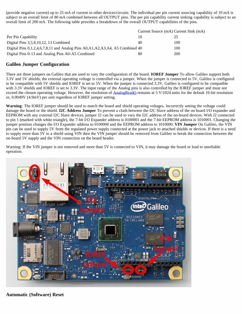
Galileo Jumper Configuration
There are three jumpers on Galileo that are used to vary the configuration of the board. IOREF Jumper To allow Galileo support both3.3V and 5V shields, the external operating voltage is controlled via a jumper. When the jumper is connected to 5V, Galileo is configuredto be compatible with 5V shields and IOREF is set to 5V. When the jumper is connected 3.3V, Galileo is configured to be compatiblewith 3.3V shields and IOREF is set to 3.3V. The input range of the Analog pins is also controlled by the IOREF jumper and must notexceed the chosen operating voltage. However, the resolution of AnalogRead() remains at 5 V/1024 units for the default 10-bit resolutionor, 0.0049V (4.9mV) per unit regardless of IOREF jumper setting.
Warning: The IOREF jumper should be used to match the board and shield operating voltages. Incorrectly setting the voltage coulddamage the board or the shield. I2C Address Jumper To prevent a clash between the I2C Slave address of the on board I/O expander andEEPROM with any external I2C Slave devices, jumper J2 can be used to vary the I2C address of the on-board devices. With J2 connectedto pin 1 (marked with white triangle), the 7-bit I/O Expander address is 0100001 and the 7-bit EEPROM address is 1010001. Changing thejumper position changes the I/O Expander address to 0100000 and the EEPROM address to 1010000. VIN Jumper On Galileo, the VINpin can be used to supply 5V from the regulated power supply connected at the power jack to attached shields or devices. If there is a needto supply more than 5V to a shield using VIN then the VIN jumper should be removed from Galileo to break the connection between theon-board 5V supply and the VIN connection on the board header.
Warning: If the VIN jumper is not removed and more than 5V is connected to VIN, it may damage the board or lead to unreliableoperation.
Automatic (Software) Reset

Rather than requiring a physical press of the reset button before an upload, Galileo is designed in a way that allows it to be reset bysoftware running on a connected computer. USB CDC-ACM control signals are used to transition Galileo from run-time to bootloadermode. The Arduino software uses this capability to allow you to upload code by simply pressing the upload button in the Arduinoenvironment. For details, see the Intel® Galileo Getting Started Guide.
Physical Characteristics
Galileo is 4.2 inches long and 2.8 inches wide respectively, with the USB connectors, UART jack, Ethernet connector, and power jackextending beyond the former dimension. Four screw holes allow the board to be attached to a surface or case. Note that the distancebetween digital pins 7 and 8 is 160 mil (0.16"), is not an even multiple of the 100 mil spacing of the other pins.
Intel® Galileo Design Document
This Intel® Galileo design document is licensed by Intel under the terms of the Creative Commons Attribution Share-Alike License (ver.3), subject to the following terms and conditions. The Intel® Galileo design document IS PROVIDED "AS IS" AND "WITH ALLFAULTS." Intel DISCLAIMS ALL OTHER WARRANTIES, EXPRESS OR IMPLIED REGARDING THE GALILEO DESIGN ORTHIS GALILEO DESIGN DOCUMENT INCLUDING, BUT NOT LIMITED TO, ANY IMPLIED WARRANTIES OFMERCHANTABILITY OR FITNESS FOR A PARTICULAR PURPOSE. Intel® may make changes to the specifications, schematics andproduct descriptions at any time, without notice. The Customer must not rely on the absence or characteristics of any features orinstructions marked "reserved" or "undefined." Intel® reserves these for future definition and shall have no responsibility whatsoever forconflicts or incompatibilities arising from future changes to them. ENJOY!