integration and commissioning of the ariel e
TRANSCRIPT
Physics Procedia 67 ( 2015 ) 857 – 862
Available online at www.sciencedirect.com
1875-3892 Crown Copyright © 2015 The Authors. Published by Elsevier B.V. This is an open access article under the CC BY-NC-ND license (http://creativecommons.org/licenses/by-nc-nd/4.0/).Peer-review under responsibility of the organizing committee of ICEC 25-ICMC 2014doi: 10.1016/j.phpro.2015.06.144
ScienceDirect
25th International Cryogenic Engineering Conference and the International Cryogenic Materials Conference in 2014, ICEC 25–ICMC 2014
Integration and commissioning of the ARIEL e-linac cryogenic system at TRIUMF
Alexey Koveshnikov*, Iouri Bylinskii, Geoff Hodgson, Shane Koscielniak, Ruslan Nagimov, Dimo Yosifov
TRIUMF, 4004 Wesbrook Mall, Vancouver, V6T 2A3, Canada
Abstract
The Advanced Rare IsotopE Laboratory (ARIEL) is a major expansion of the Isotope Separation and Acceleration (ISAC) facility at TRIUMF. The key part of the ARIEL project is a superconducting radiofrequency (SRF) linear electron accelerator (e-linac). The e-linac helium cryogenic system was designed to meet the ARIEL specifications. The HELIAL LL helium liquefier by Air Liquide Advanced Technologies supplies 4 K liquid helium (LHe) to cryomodules via a LHe distribution system. The cryomodules have a top-loaded-cold mass design. The 4 K – 2 K temperature conversion is achieved by a counter flow heat exchanger and a JT-valve installed onboard each cryomodule [1]. The temperature in the 2 K volume of the cryomodules is controlled by pressure control in the sub-atmospheric line. Sub-atmospheric helium is warmed up in a custom-designed heat exchanger and after passing sub-atmospheric pumps goes to the helium compressor suction line. The LN2 system supplies liquid nitrogen to the liquefier, 80 K shielding of the cryomodules and LHe distribution system, as well as to the freeze-out helium purifier. The installation of the e-linac cryogenic system components started in February 2013 while the corresponding subsystems tests started in November 2013.This paper describes the e-linac cryogenic system components integration and presents the results of the acceptance tests and commissioning activities performed at TRIUMF since November 2013.
© 2014 The Authors. Published by Elsevier B.V.Peer-review under responsibility of the organizing committee of ICEC 25-ICMC 2014.
Keywords: coldbox; commissioning; cryogenics; cryomodule; helium liqufaction; helium refrigeration
* Corresponding author. Tel.: +1-604-222-1047 ext. 7381; fax: +1-604-222-1074.E-mail address: [email protected]
Crown Copyright © 2015 The Authors. Published by Elsevier B.V. This is an open access article under the CC BY-NC-ND license (http://creativecommons.org/licenses/by-nc-nd/4.0/).Peer-review under responsibility of the organizing committee of ICEC 25-ICMC 2014
brought to you by COREView metadata, citation and similar papers at core.ac.uk
provided by Elsevier - Publisher Connector
858 Alexey Koveshnikov et al. / Physics Procedia 67 ( 2015 ) 857 – 862
1. Introduction
The Advanced Rare IsotopE Laboratory (ARIEL) is TRIUMF's facility that will expand Canada's capabilities to produce and study isotopes for physics, materials science and medicine. Utilizing SRF technology, it will showcase ahigh-power electron accelerator to produce exotic isotopes for research and development. [2]. A key part of the ARIEL project is a 10 mA-50 MeV continuous-wave superconducting radiofrequency (SRF) electron linear accelerator (e-linac). The 1.3GHz SRF cavities are cooled by 2 K liquid helium [3]. Liquid helium at 4 K is produced by the Helial LL cryoplant supplied by Air Liquide Advanced Technologies. 2 K liquid helium is generated inside each cryomodule [4]. After successful commissioning of the 4 K cryoplant, a 2 K sub-atmospheric (SA) system was installed. Ultimate integration test aims to operate two cryomodules containing a total of three 9-cell SRF cavities. Particularities of this cryogenic system include the top loading design of the cryomodules, the 2 Kliquid helium production on-board of each cryomodule, the conservative design of the oil removal system, the original passive heater in the SA pumping system, the hermetic dry SA pumps, the inline full S/A flow helium purifier, the multipurpose recovery/purification compressor, the sectioned cold helium distribution system, and the overall system radiation resistant design.
2. ARIEL e-linac cryogenic system structure
The ARIEL e-linac project is developed in two main stages. The first project stage, ARIEL phase I, includes two cryomodules (Injector Cryomodule and Accelerator Cryomodule #1). A third cryomodule will be added in ARIEL phase II. The cryogenic system follows the ARIEL project requirements. The overall structure of the ARIEL cryogenic system is shown on Fig 1.
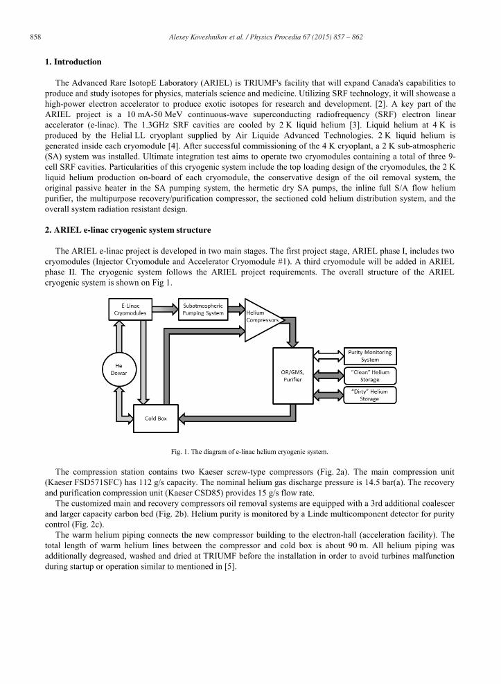
Fig. 1. The diagram of e-linac helium cryogenic system.
The compression station contains two Kaeser screw-type compressors (Fig. 2a). The main compression unit (Kaeser FSD571SFC) has 112 g/s capacity. The nominal helium gas discharge pressure is 14.5 bar(a). The recovery and purification compression unit (Kaeser CSD85) provides 15 g/s flow rate.
The customized main and recovery compressors oil removal systems are equipped with a 3rd additional coalescer and larger capacity carbon bed (Fig. 2b). Helium purity is monitored by a Linde multicomponent detector for purity control (Fig. 2c).
The warm helium piping connects the new compressor building to the electron-hall (acceleration facility). The total length of warm helium lines between the compressor and cold box is about 90 m. All helium piping was additionally degreased, washed and dried at TRIUMF before the installation in order to avoid turbines malfunction during startup or operation similar to mentioned in [5].
Alexey Koveshnikov et al. / Physics Procedia 67 ( 2015 ) 857 – 862 859
a b c
Fig. 2. (a) Main and recovery compressors; (b) main compressor oil removal system; (c) multicomponent purity analyzer.
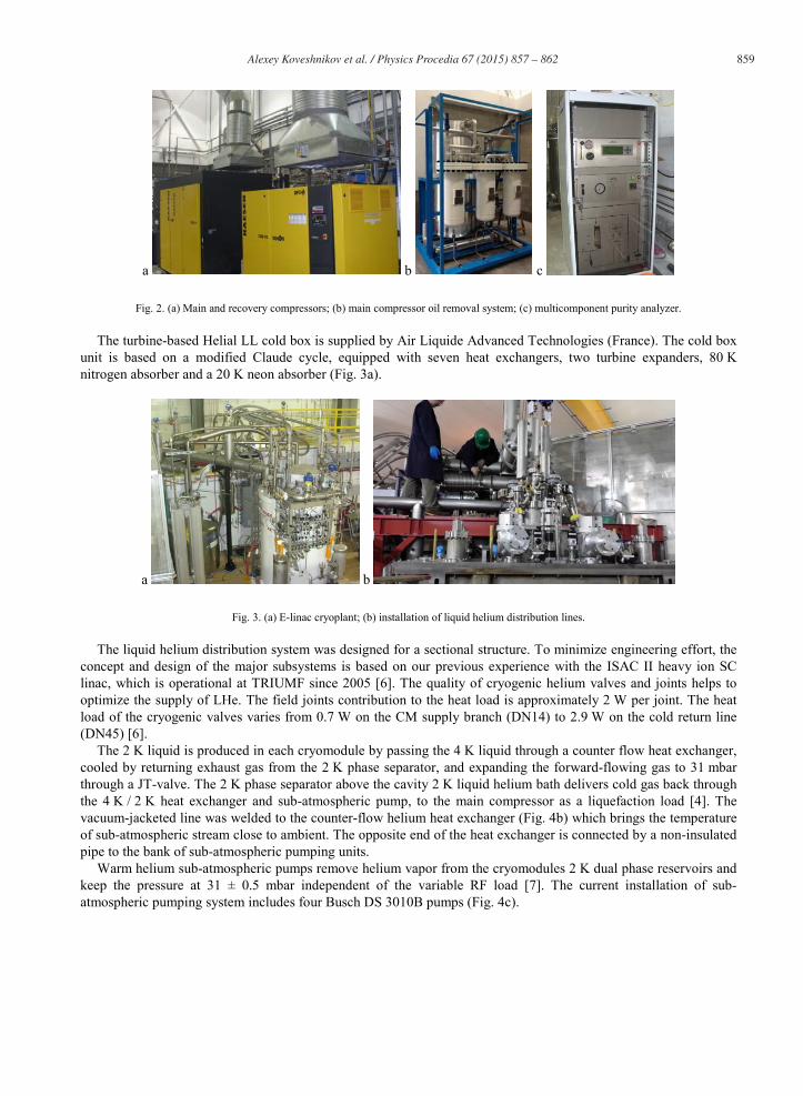
The turbine-based Helial LL cold box is supplied by Air Liquide Advanced Technologies (France). The cold box unit is based on a modified Claude cycle, equipped with seven heat exchangers, two turbine expanders, 80 Knitrogen absorber and a 20 K neon absorber (Fig. 3a).
a b
Fig. 3. (a) E-linac cryoplant; (b) installation of liquid helium distribution lines.
The liquid helium distribution system was designed for a sectional structure. To minimize engineering effort, the concept and design of the major subsystems is based on our previous experience with the ISAC II heavy ion SC linac, which is operational at TRIUMF since 2005 [6]. The quality of cryogenic helium valves and joints helps to optimize the supply of LHe. The field joints contribution to the heat load is approximately 2 W per joint. The heat load of the cryogenic valves varies from 0.7 W on the CM supply branch (DN14) to 2.9 W on the cold return line (DN45) [6].
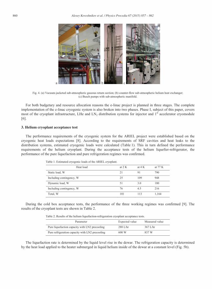
The 2 K liquid is produced in each cryomodule by passing the 4 K liquid through a counter flow heat exchanger,cooled by returning exhaust gas from the 2 K phase separator, and expanding the forward-flowing gas to 31 mbarthrough a JT-valve. The 2 K phase separator above the cavity 2 K liquid helium bath delivers cold gas back through the 4 K / 2 K heat exchanger and sub-atmospheric pump, to the main compressor as a liquefaction load [4]. The vacuum-jacketed line was welded to the counter-flow helium heat exchanger (Fig. 4b) which brings the temperature of sub-atmospheric stream close to ambient. The opposite end of the heat exchanger is connected by a non-insulated pipe to the bank of sub-atmospheric pumping units.
Warm helium sub-atmospheric pumps remove helium vapor from the cryomodules 2 K dual phase reservoirs and keep the pressure at 31 ± 0.5 mbar independent of the variable RF load [7]. The current installation of sub-atmospheric pumping system includes four Busch DS 3010B pumps (Fig. 4c).
860 Alexey Koveshnikov et al. / Physics Procedia 67 ( 2015 ) 857 – 862
a b c
Fig. 4. (a) Vacuum-jacketed sub-atmospheric gaseous return section; (b) counter-flow sub-atmospheric helium heat exchanger;(c) Busch pumps with sub-atmospheric manifold.
For both budgetary and resource allocation reasons the e-linac project is planned in three stages. The complete implementation of the e-linac cryogenic system is also broken into two phases. Phase I, subject of this paper, covers most of the cryoplant infrastructure, LHe and LN2 distribution systems for injector and 1st accelerator cryomodule[6].
3. Helium cryoplant acceptance test
The performance requirements of the cryogenic system for the ARIEL project were established based on the cryogenic heat loads expectations [8]. According to the requirements of SRF cavities and heat leaks to the distribution systems, estimated cryogenic loads were calculated (Table 1). This in turn defined the performancerequirements of the helium cryoplant. During the acceptance tests of the helium liquefier-refrigerator, the performance of the pure liquefaction and pure refrigeration regimes was confirmed.
Table 1. Estimated cryogenic loads of the ARIEL cryoplant.
Heat load at 2 K at 4 K at 77 K
Static load, W 21 91 790
Including contingency, W 25 109 948
Dynamic load, W 51 3.0 180
Including contingency, W 76 4.5 216
Total, W 101 113 1,164
During the cold box acceptance tests, the performance of the three working regimes was confirmed [9]. The results of the cryoplant tests are shown in Table 2.
Table 2. Results of the helium liquefaction-refrigeration cryoplant acceptance tests.
Parameter Expected value Measured value
Pure liquefaction capacity with LN2 precooling 288 L/hr 367 L/hr
Pure refrigeration capacity with LN2 precooling 600 W 837 W
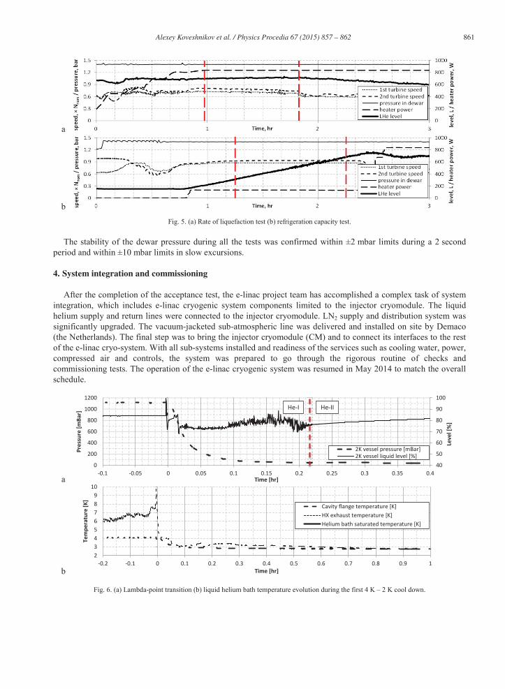
The liquefaction rate is determined by the liquid level rise in the dewar. The refrigeration capacity is determined by the heat load applied to the heater submerged in liquid helium inside of the dewar at a constant level (Fig. 5b).
Alexey Koveshnikov et al. / Physics Procedia 67 ( 2015 ) 857 – 862 861
a
b
Fig. 5. (a) Rate of liquefaction test (b) refrigeration capacity test.
The stability of the dewar pressure during all the tests was confirmed within ±2 mbar limits during a 2 second period and within ±10 mbar limits in slow excursions.
4. System integration and commissioning
After the completion of the acceptance test, the e-linac project team has accomplished a complex task of system integration, which includes e-linac cryogenic system components limited to the injector cryomodule. The liquid helium supply and return lines were connected to the injector cryomodule. LN2 supply and distribution system was significantly upgraded. The vacuum-jacketed sub-atmospheric line was delivered and installed on site by Demaco (the Netherlands). The final step was to bring the injector cryomodule (CM) and to connect its interfaces to the rest of the e-linac cryo-system. With all sub-systems installed and readiness of the services such as cooling water, power, compressed air and controls, the system was prepared to go through the rigorous routine of checks and commissioning tests. The operation of the e-linac cryogenic system was resumed in May 2014 to match the overall schedule.
a
b
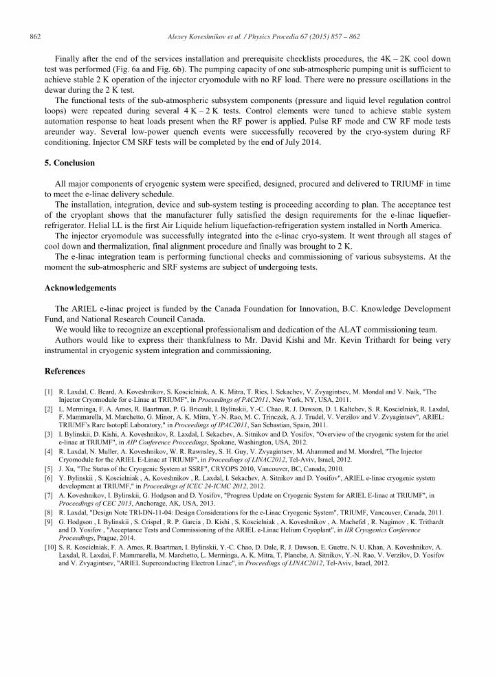
Fig. 6. (a) Lambda-point transition (b) liquid helium bath temperature evolution during the first 4 K – 2 K cool down.
40
50
60
70
80
90
100
0
200
400
600
800
1000
1200
-0.1 -0.05 0 0.05 0.1 0.15 0.2 0.25 0.3 0.35 0.4
Pres
sure
[mBa
r]
Time [hr]
2K vessel pressure [mBar]2K vessel liquid level [%]
Leve
l [%
]
He-IIHe-I
23456789
10
-0.2 -0.1 0 0.1 0.2 0.3 0.4 0.5 0.6 0.7 0.8 0.9 1
Tem
pera
ture
[K]
Time [hr]
Cavity flange temperature [K]HX exhaust temperature [K]Helium bath saturated temperature [K]
862 Alexey Koveshnikov et al. / Physics Procedia 67 ( 2015 ) 857 – 862
Finally after the end of the services installation and prerequisite checklists procedures, the 4K – 2K cool down test was performed (Fig. 6a and Fig. 6b). The pumping capacity of one sub-atmospheric pumping unit is sufficient toachieve stable 2 K operation of the injector cryomodule with no RF load. There were no pressure oscillations in the dewar during the 2 K test.
The functional tests of the sub-atmospheric subsystem components (pressure and liquid level regulation control loops) were repeated during several 4 K – 2 K tests. Control elements were tuned to achieve stable system automation response to heat loads present when the RF power is applied. Pulse RF mode and CW RF mode tests areunder way. Several low-power quench events were successfully recovered by the cryo-system during RF conditioning. Injector CM SRF tests will be completed by the end of July 2014.
5. Conclusion
All major components of cryogenic system were specified, designed, procured and delivered to TRIUMF in time to meet the e-linac delivery schedule.
The installation, integration, device and sub-system testing is proceeding according to plan. The acceptance test of the cryoplant shows that the manufacturer fully satisfied the design requirements for the e-linac liquefier-refrigerator. Helial LL is the first Air Liquide helium liquefaction-refrigeration system installed in North America.
The injector cryomodule was successfully integrated into the e-linac cryo-system. It went through all stages of cool down and thermalization, final alignment procedure and finally was brought to 2 K.
The e-linac integration team is performing functional checks and commissioning of various subsystems. At the moment the sub-atmospheric and SRF systems are subject of undergoing tests.
Acknowledgements
The ARIEL e-linac project is funded by the Canada Foundation for Innovation, B.C. Knowledge Development Fund, and National Research Council Canada.
We would like to recognize an exceptional professionalism and dedication of the ALAT commissioning team.Authors would like to express their thankfulness to Mr. David Kishi and Mr. Kevin Trithardt for being very
instrumental in cryogenic system integration and commissioning.
References
[1] R. Laxdal, C. Beard, A. Koveshnikov, S. Koscielniak, A. K. Mitra, T. Ries, I. Sekachev, V. Zvyagintsev, M. Mondal and V. Naik, "The Injector Cryomodule for e-Linac at TRIUMF", in Proceedings of PAC2011, New York, NY, USA, 2011.
[2] L. Merminga, F. A. Ames, R. Baartman, P. G. Bricault, I. Bylinskii, Y.-C. Chao, R. J. Dawson, D. I. Kaltchev, S. R. Koscielniak, R. Laxdal, F. Mammarella, M. Marchetto, G. Minor, A. K. Mitra, Y.-N. Rao, M. C. Trinczek, A. J. Trudel, V. Verzilov and V. Zvyagintsev", ARIEL: TRIUMF’s Rare IsotopE Laboratory," in Proceedings of IPAC2011, San Sebastian, Spain, 2011.
[3] I. Bylinskii, D. Kishi, A. Koveshnikov, R. Laxdal, I. Sekachev, A. Sitnikov and D. Yosifov, "Overview of the cryogenic system for the ariel e-linac at TRIUMF", in AIP Conference Proceedings, Spokane, Washington, USA, 2012.
[4] R. Laxdal, N. Muller, A. Koveshnikov, W. R. Rawnsley, S. H. Guy, V. Zvyagintsev, M. Ahammed and M. Mondrel, "The Injector Cryomodule for the ARIEL E-Linac at TRIUMF", in Proceedings of LINAC2012, Tel-Aviv, Israel, 2012.
[5] J. Xu, "The Status of the Cryogenic System at SSRF", CRYOPS 2010, Vancouver, BC, Canada, 2010.[6] Y. Bylinskii , S. Koscielniak , A. Koveshnikov , R. Laxdal, I. Sekachev, A. Sitnikov and D. Yosifov", ARIEL e-linac cryogenic system
development at TRIUMF," in Proceedings of ICEC 24-ICMC 2012, 2012. [7] A. Koveshnikov, I. Bylinskii, G. Hodgson and D. Yosifov, "Progress Update on Cryogenic System for ARIEL E-linac at TRIUMF", in
Proceedings of CEC 2013, Anchorage, AK, USA, 2013. [8] R. Laxdal, "Design Note TRI-DN-11-04: Design Considerations for the e-Linac Cryogenic System", TRIUMF, Vancouver, Canada, 2011.[9] G. Hodgson , I. Bylinskii , S. Crispel , R. P. Garcia , D. Kishi , S. Koscielniak , A. Koveshnikov , A. Machefel , R. Nagimov , K. Trithardt
and D. Yosifov , "Acceptance Tests and Commissioning of the ARIEL e-Linac Helium Cryoplant", in IIR Cryogenics Conference Proceedings, Prague, 2014.
[10] S. R. Koscielniak, F. A. Ames, R. Baartman, I. Bylinskii, Y.-C. Chao, D. Dale, R. J. Dawson, E. Guetre, N. U. Khan, A. Koveshnikov, A. Laxdal, R. Laxdai, F. Mammarella, M. Marchetto, L. Merminga, A. K. Mitra, T. Planche, A. Sitnikov, Y.-N. Rao, V. Verzilov, D. Yosifov and V. Zvyagintsev, "ARIEL Superconducting Electron Linac", in Proceedings of LINAC2012, Tel-Aviv, Israel, 2012.