integrating safety and automation - american society of ... · pdf file• a afeguard is a...
TRANSCRIPT
866-522-2300 / www.asesafety.com
Integrating Safety and Automation
Presented by: Dennis Aulbrook

• A safeguard is a solution or a combination of solutions that eliminate or reduce the risk of exposure to hazardous moving parts and other hazards.
• Appropriate safeguards must be integrated into the machinery/automation system to mitigate the hazard(s).
• The criteria for selecting proper techniques & safeguarding will be discussed today.
• Common cause failures of automation systems and why you must protect against those failures will also be discussed.
Safeguarding of Automated Machinery

3
Hierarchy of Safeguards
Design out the hazard(s)
Fixed barrier guarding
Safeguarding Devices/Energy Control
Awareness Means, Training, Procedures, Safe Location (Admin.)
Personal Protective Equipment
Most effective risk reduction
Least effective risk reduction
Safeguarding & risk reduction

866-522-2300 / www.asesafety.com
Barrier Guarding Safeguarding Devices Energy Control
But first a short review of the regulations; risk
assessments and safety circuits
Safeguarding topics covered today

What guidelines are there for designing a safety system?
Mandatory (Law) Federal - Occupational Safety & Health Administration (OSHA) State - Occupational Safety & Health Administration (XXOSHA) Consensus Standards (Voluntary) American National Standards Institute (ANSI) National Fire Protection Agency (NFPA) Canadian Standards Association (CSA) European Norm (EN) International Electro technical Commission (IEC) International Organization for Standardization (ISO)

Risk Assessments to determine appropriate safeguarding
Risk Assessment flow chart as per ISO 12100
Hazard identification and risk evaluation are done first. Then follow-thru steps are taken to determine that the risk has been reduced to the acceptable level.
Note: ISO 12100 replaced ISO 14121 in 2012 and is referenced in ANSI (i.e. Robot Safety Standard) and other ISO standards (i.e. ISO 13849 Safety of Machinery)

How do I determine the level of safeguarding required?
Safety Performance Levels (PLr) according to ISO 13849
Severity of injury (S); Frequency of exposure (F) and Possibility to avoid (P) drive the Performance Level (PLr) of overall safeguarding required to reduce the risk(s)

8
What is Control Reliability?
Cardinal Rule: No single failure will cause the loss of safety!
Control Reliable circuits are designed with redundancy and monitoring PLd - monitoring can be done each machine cycle and is fault tolerant; where PLe employs
continuous monitoring and is not fault tolerant. PLe must also have a “diversity” of components. Control reliability is required in OSHA 1910.217 as well as many ANSI, NFPA, CSA, EN and ISO
standards. Control reliable is not the same as “fail-safe”. Fail-Safe simply means that a circuit should fail to
its safe state.
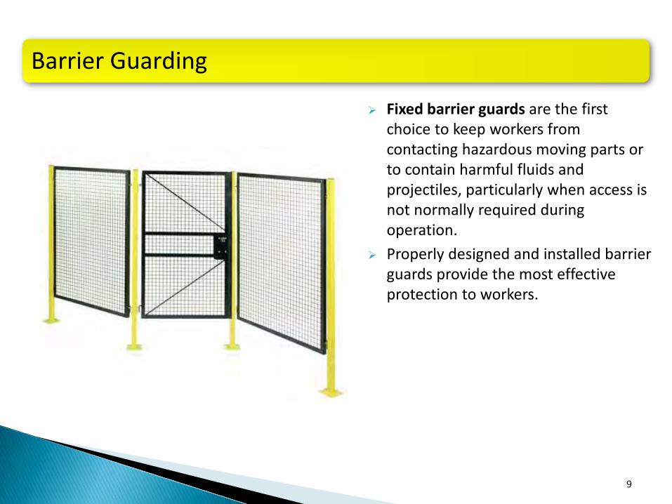
Fixed barrier guards are the first choice to keep workers from contacting hazardous moving parts or to contain harmful fluids and projectiles, particularly when access is not normally required during operation.
Properly designed and installed barrier guards provide the most effective protection to workers.
9
Barrier Guarding

Fixed barrier guards must: Prevent access to the danger area
from all directions (AUTO: Around, Under, Through, Over)
Not create additional pinch points or other hazards
Withstand operational forces Safely contain broken parts;
projectiles; hazardous fluids etc. Be secured by at least one fastener
requiring an uncommon tool for removal, unless properly interlocked with the machine control system.
10
Design & Performance Requirements
Barrier Guarding

Fixed barrier guards must also: • Offer good visibility when possible • Stand up to normal wear and tear • Meet normal production and quality
needs • Be difficult to modify or defeat • Allow for safe lubrication and/or minor
adjustments • Meet or exceed federal/state and
industry consensus requirements: United States = OSHA/ANSI B11; Canada = CSA; International = ISO
11
Design & Performance Requirements
Barrier Guarding

Relationship between size of opening in a grid guard and distance to the danger point. Note: check all applicable federal, state, international & consensus requirements.
Maximum permissible openings
Barrier Guarding

Perimeter guarding (fence) or rail enclosure can be used to effectively protect a worker from contacting hazards.
Where possible, a perimeter fence or rail enclosure should be at least 1.8 meters (6 feet) high. If this is not practicable, the reach distance from the guardrail or perimeter fence to the danger point must be in accordance with federal & industry consensus standards.
Minimum perimeter guarding height (in most standards) is 1000mm (40”) to restrict body movement.
Maximum sweep height (bottom opening) is 150mm (6”).
Factors to consider in designing perimeter Guarding: A = height of the danger zone, B = height of the protective barrier, C = horizontal distance to the danger zone.
Note: check all applicable federal, state, international & consensus requirements.
Reach distances to hazard(s)
Perimeter Guarding
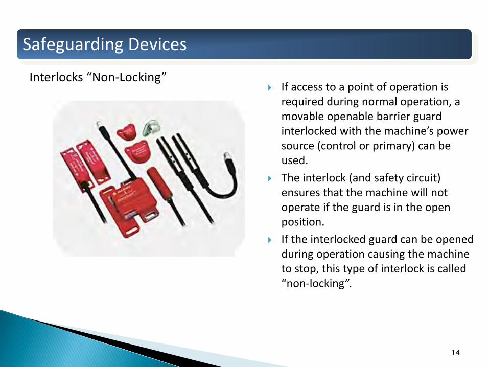
If access to a point of operation is required during normal operation, a movable openable barrier guard interlocked with the machine’s power source (control or primary) can be used.
The interlock (and safety circuit) ensures that the machine will not operate if the guard is in the open position.
If the interlocked guard can be opened during operation causing the machine to stop, this type of interlock is called “non-locking”.
14
Safeguarding Devices
Interlocks “Non-Locking”

Some interlock switches also have a locking device that locks the guard door closed and will not release it until the machine comes to a safe stop.
They are typically used with machinery where the coasting down time may take several seconds to several minutes.
This type of interlock is also referred to as power interlocking and can be configured for power-to-lock or power-to-unlock.
Generally, a “Request-To-Enter” (RTE) operator station is required to stop the machine before the interlock unlocks.
Zero speed indication can be accomplished with time, encoders or back EMF; depending on risk. 15
Safeguarding Devices
Interlocks “Locking”
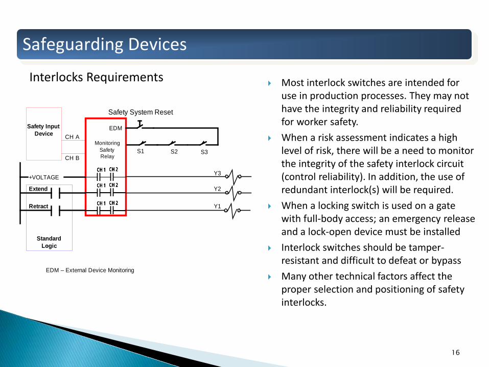
Most interlock switches are intended for use in production processes. They may not have the integrity and reliability required for worker safety.
When a risk assessment indicates a high level of risk, there will be a need to monitor the integrity of the safety interlock circuit (control reliability). In addition, the use of redundant interlock(s) will be required.
When a locking switch is used on a gate with full-body access; an emergency release and a lock-open device must be installed
Interlock switches should be tamper-resistant and difficult to defeat or bypass
Many other technical factors affect the proper selection and positioning of safety interlocks.
16
CH 1 CH 2CH 1 CH 2CH 1 CH 2CH 1 CH 2
CH 1 CH 2CH 1 CH 2CH 1 CH 2CH 1 CH 2
CH 1 CH 2CH 1 CH 2CH 1 CH 2CH 1 CH 2
Extend
Retract
Standard Logic
Safety Input Device CH A
CH B
+VOLTAGE
EDM
EDM – External Device Monitoring
S1 S2 S3
Safety System Reset
Y3
Y2
Y1
Monitoring Safety Relay
Safeguarding Devices
Interlocks Requirements

Trapped key systems (also known as Captive key systems) use a series of keys and locks to start or shut down a hazardous operation in a prescribed and safe sequence.
These devices are mechanical only (no electricity) which makes them appropriate for pneumatically operated machinery or where intrinsically safe circuits are required.
17
Safeguarding Devices
Trapped Key(s)

Two-hand controls, where both controls (buttons, levers, sensors) must be activated at the same time and kept engaged throughout the entire hazardous portion of the machine cycle. If the controls are released, the machine either stops or returns to top of stroke (the position that opens the dies). This type of machine operation is called part revolution clutch or friction clutch. It is commonly found with pneumatic clutches/brakes and with hydraulically powered machinery such as press brakes
Two-hand trips, where both controls must be activated at the same time to initiate the machine cycle but releasing the controls will not interrupt the machine cycle. This type of machine operation is called full revolution clutch or mechanical clutch
18
Safeguarding Devices
Two-Hand controls

Unlike barrier guards and two-hand controls, presence-sensing devices do not prevent access to a hazardous point of operation. However, they prevent dangerous machine motion if any part of a worker’s body is in the danger area when a machine cycle is initiated. They are a good choice of safeguard when frequent access is required for loading parts and making adjustments during normal operation and physical guarding is too restrictive. These safety devices prevent dangerous motion while permitting unrestricted access by sensing the presence of the operator and sending a stop signal. Examples include light curtains, laser scanners, IR or laser light beams etc.
19
Safeguarding Devices
Presence Sensing Devices

Safety bumpers and safety mats are “pressure sensitive” and cause a short circuit across the electrical contacts when they encounter resistance (typically 60 lbs. for mats).
Safety mats are typically used to guard the floor area around a machine. They must be a min. of 48” deep and should not be used as an “enabling” device.
Safety bumpers are typically used on power operated doors.
These devices are available in control reliable (4-wire) and non-control reliable configurations (2-wire). Be sure to select the appropriate protection based on a risk assessment.
20
Safety Mat
Safeguarding Devices
Pressure Sensitive Devices

Standard PLC’s (Programmable Logic Controllers) are not considered a safety device and should not be used as such.
Safety controllers (programmable and non-programmable) are the “brains” of the safety system. They are control reliable safety rated devices with dual channel inputs that employ continuous self-checking and are capable of open circuit detection; short-circuit detection and ground fault detection. Monitoring and error checking of peripheral safety input & output devices
21
Programmable
Safeguarding Devices
Safety Controllers - Relays and PLC’s
Safety PLC Safety Relay

An Emergency Stop (E-Stop) device is a safety mechanism used to shut off a device or machine in an emergency situation. It can be a pushbutton, pull-rope, push bar, or other device that brings about immediate stoppage of the machine when activated.
There is debate as to whether or not an emergency stop is a “safeguarding” device because it is normally used “after-the-fact”
According to NFPA, ANSI, CSA & ISO, emergency stop devices should be control reliable in high risk areas.
22
Safeguarding Devices
Emergency Stop Devices

Electrical Hydraulic Pneumatic Mechanical/Gravity All other energy sources as listed in
ISO 12100 Risk Assessment. Such as Kinetic, Chemical, Thermal, Radiation etc.
23
Common cause failures of automation systems
Energy sources that must be consider & mitigated

Any failure in the hydraulic, pneumatic or mechanical system can cause hazardous movement
Some failures modes are: Valve Spool Sticking; Short Circuit / Open Circuit on Solenoid; Broken Hose or Fitting; Mechanical Failure; Cylinder O-Ring Failure / Valve Seal Failure. Any of which can cause machine movement and/or vertical cylinders to fall.
Possible causes of these failure are: System Contamination / Lack of Filtration; Over Pressure; Over Temperature; Lack of Maintenance; Wrong Components; Fastener failures; Poor Design (wrong size, wrong type, hose length incorrect); Fatigue etc.
24
Energy Control
What could go wrong?

866-522-2300 / www.asesafety.com
Pneumatic Failure: Real Life OSHA Accident: 202655346 - Technician Sustains Amputations When Machine Actuates Employee #1 was working as a lead setup man and technician for a firm that manufactured plastic food containers. There were problems with an Irwin thermoplastic-forming machine . . . Employee #1 turned the electric power off first and opened the door to the machine. At this time, the top mold was held and controlled pneumatically in the 'top' position. As he reached into the machine to look for the problem, the top mold, or plunger, unexpectedly came down. It pinned his right hand against a westerly rail in proximity to the bottom mold. He sustained crushing injuries of his right hand, which resulted in the amputation of the fingertips . . . the Division determined that the pneumatically controlled top mold of the forming machine had been coming down by itself unexpectedly in the past, regardless of whether the machine door was in the 'closed' or 'open' position.

SOL1
26
Electrical Coil/Solenoid
2 Position Valve, 3 Ports P – Pressure E – Exhaust A – Port to Cylinder
Energy Control
3-Way pneumatic valve review
Spring
P E
A To Cylinder or Actuator From Air Supply
When Solenoid is NOT Energized, P-Port is blocked and A-Port is routed to Exhaust Port-E

SOL1
27
Electrical Coil/Solenoid
2 Position Valve, 3 Ports P – Pressure E – Exhaust A – Port to Cylinder
Energy Control
3-Way pneumatic valve review
Spring
P E
A To Cylinder or Actuator From Air Supply
When Solenoid is Energized, P-Port is routed to A-Port and Exhaust Port-E is blocked

28
Safety Function: When the electrical command signals are removed, the valve exhausts air from the hazardous cylinder or actuator of the machine.
Faults to Consider: • Valve stuck in actuated position. • Pilot seal failure – Can lead to unexpected valve element movement • Pilot section manual actuator seal failure - Can lead to unexpected valve element movement • Valve element not actuating or de-actuating properly due to fluid contamination or internal wear. • Broken components (piston, poppet, spring) within a valve element could cause valve to shift unexpectedly or not shift.
Fault Exclusion: None
Hazardous Portionof Machine
SOL1
From Air Prep(see General Considerations)
Note: There is no “monitoring” of the components by the control system
Energy Control
Single Channel Pneumatic Circuit (PLb)

29
CH 1 CH 2CH 1 CH 2CH 1 CH 2CH 1 CH 2
CH 1 CH 2CH 1 CH 2CH 1 CH 2CH 1 CH 2
CH 1 CH 2CH 1 CH 2CH 1 CH 2CH 1 CH 2
Air Motor On
Standard Logic
Safety Input Device CH A
+VOLTAGE
EDM
EDM – External Device Monitoring
LS1
Safety System Reset
SOL1
Monitoring Safety Relay
Hazardous Portionof Machine
From Air Prep(see General Considerations)
LS1
Poppet Valve
SOL1
The “monitoring” function checks the Safety Input Device and also the pneumatic valve (via LS1)
This pneumatic circuit is not “control reliable” because there is no valve redundancy to prevent a single valve failure that could cause the loss of safety
Energy Control
Single Channel Pneumatic Circuit with monitoring (PLc)

30
Air and Hydraulic Cylinders: A Pilot Operated (PO) Check Valve would engage once the pressure source is isolated. This would hold the cylinder in a suspended state. If the seals are bad, the cylinder would drift. A second PO check valve on the cap end of the cylinder would resolve a leakage problem. Counter-balance valves can accomplish the same goals.
Other Benefits: The cylinder would remain stationary on the loss of voltage, loss of air pressure or decoupled hose(s), if the PO check(s) were installed directly into the cylinder ports.
Energy Control
Vertical Load Holding – PO checks & Counter Balance valves

31
Ratchet Style Mechanical Safety monitored by safety system
Manual Die Blocks, use of administrative controls required. Rod Locks monitored by
safety system
Energy Control
Vertical Load Holding – Mechanical

866-522-2300 / www.asesafety.com
Questions?
If you have questions; would like a copy of this presentation or would like to schedule a live demonstration at your facility, please contact
[email protected] or call 810-417-0220
Thank you!!