integrated transmitter architectures for 4g networks … · integrated transmitter architectures...
TRANSCRIPT
INTEGRATED TRANSMITTER ARCHITECTURES
FOR 4G NETWORKS AND BEYOND
Martin Schleyer, Adel Fatemi | Fachgebiet Mikroelektronik
Literature Recommendations
[Dahlman2011] Dahlman, E.; Parkvall, S. & Skold, J.:
4G: LTE/LTE-Advanced for Mobile Broadband
[Holma2007] Holma, H. & Toskala, A:
WCDMA for UMTS: HSPA Evolution and LTE:
[Holma2009] Holma, H. & Toskala, A:
LTE for UMTS - OFDMA and SC-FDMA Based Radio Access
[Myung2008] Myung, H. G. & Goodman, D.:
Single Carrier FDMA: A New Air Interface for Long Term Evolution
[Sauter2011] Sauter, M.: From GSM to LTE:
An Introduction to Mobile Networks and Mobile Broadband:
Available at http://www.meis.tu-berlin.de/?id=141359
Integrated Transmitter Architectures for 4G Networks and beyond | M. Schleyer, A. Fatemi | Session 2
Seite 2
EDGE AND EDGE-EVO3GPP DATA SERVICES
Integrated Transmitter Architectures for 4G Networks and beyond | M. Schleyer, A. Fatemi | Session 2
Seite 3
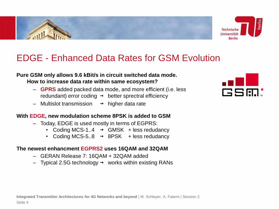
EDGE - Enhanced Data Rates for GSM Evolution
Pure GSM only allows 9.6 kBit/s in circuit switched data mode.
How to increase data rate within same ecosystem?
– GPRS added packed data mode, and more efficient (i.e. less
redundant) error coding better sprectral efficiency
– Multislot transmission higher data rate
With EDGE, new modulation scheme 8PSK is added to GSM
– Today, EDGE is used mostly in terms of EGPRS:
• Coding MCS-1..4 GMSK + less redudancy
• Coding MCS-5..8 8PSK + less redudancy
The newest enhancment EGPRS2 uses 16QAM and 32QAM
– GERAN Release 7: 16QAM + 32QAM added
– Typical 2.5G technology works within existing RANs
Integrated Transmitter Architectures for 4G Networks and beyond | M. Schleyer, A. Fatemi | Session 2
Seite 4
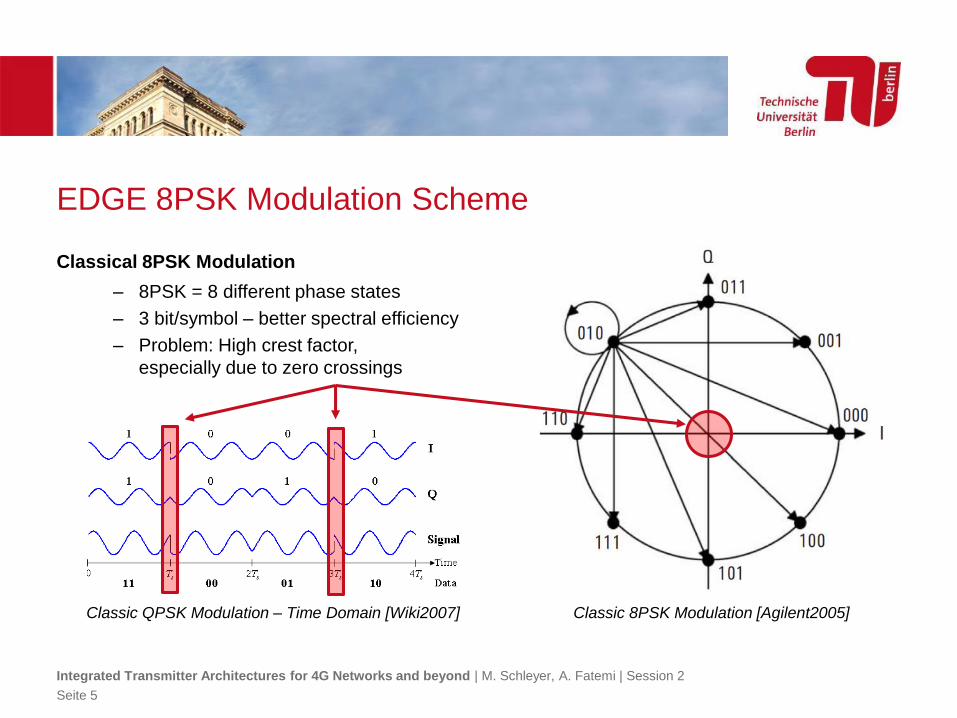
EDGE 8PSK Modulation Scheme
Classical 8PSK Modulation
– 8PSK = 8 different phase states
– 3 bit/symbol – better spectral efficiency
– Problem: High crest factor,
especially due to zero crossings
Integrated Transmitter Architectures for 4G Networks and beyond | M. Schleyer, A. Fatemi | Session 2
Seite 5
Classic 8PSK Modulation [Agilent2005]Classic QPSK Modulation – Time Domain [Wiki2007]
EDGE 8PSK Modulation Scheme
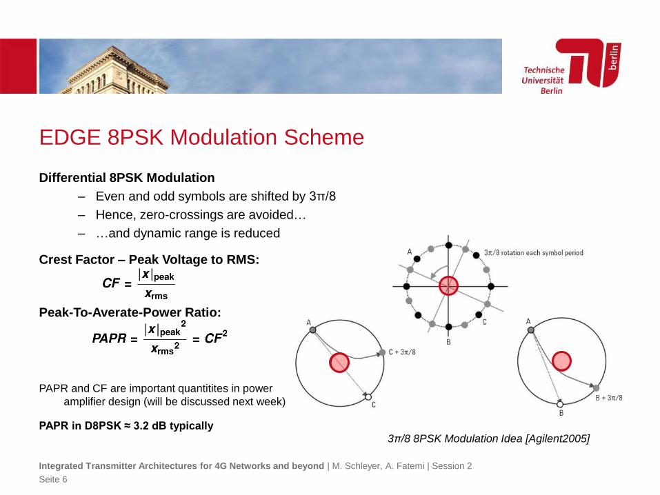
Differential 8PSK Modulation
– Even and odd symbols are shifted by 3π/8
– Hence, zero-crossings are avoided…
– …and dynamic range is reduced
Crest Factor – Peak Voltage to RMS:
Peak-To-Averate-Power Ratio:
PAPR and CF are important quantitites in power
amplifier design (will be discussed next week)
PAPR in D8PSK ≈ 3.2 dB typically
Integrated Transmitter Architectures for 4G Networks and beyond | M. Schleyer, A. Fatemi | Session 2
Seite 6
3π/8 8PSK Modulation Idea [Agilent2005]
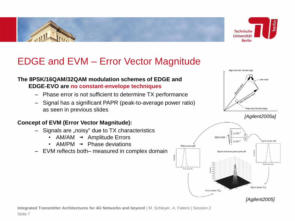
EDGE and EVM – Error Vector Magnitude
The 8PSK/16QAM/32QAM modulation schemes of EDGE and
EDGE-EVO are no constant-envelope techniques
– Phase error is not sufficient to determine TX performance
– Signal has a significant PAPR (peak-to-average power ratio)
as seen in previous slides
Concept of EVM (Error Vector Magnitude):
– Signals are „noisy“ due to TX characteristics
• AM/AM Amplitude Errors
• AM/PM Phase deviations
– EVM reflects both– measured in complex domain
Integrated Transmitter Architectures for 4G Networks and beyond | M. Schleyer, A. Fatemi | Session 2
Seite 7
[Agilent2005]
[Agilent2005a]
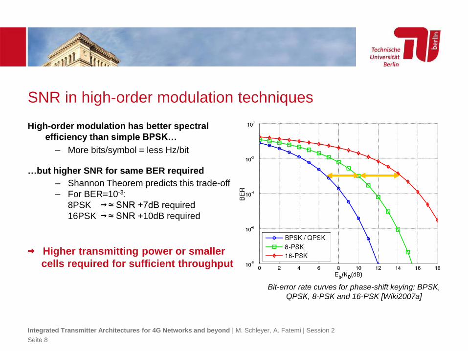
SNR in high-order modulation techniques
High-order modulation has better spectral
efficiency than simple BPSK…
– More bits/symbol = less Hz/bit
…but higher SNR for same BER required
– Shannon Theorem predicts this trade-off
– For BER=10-3:
8PSK ≈ SNR +7dB required
16PSK ≈ SNR +10dB required
Higher transmitting power or smaller
cells required for sufficient throughput
Integrated Transmitter Architectures for 4G Networks and beyond | M. Schleyer, A. Fatemi | Session 2
Seite 8
Bit-error rate curves for phase-shift keying: BPSK,
QPSK, 8-PSK and 16-PSK [Wiki2007a]
UMTS DATA SERVICES3GPP DATA SERVICES
Integrated Transmitter Architectures for 4G Networks and beyond | M. Schleyer, A. Fatemi | Session 2
Seite 9
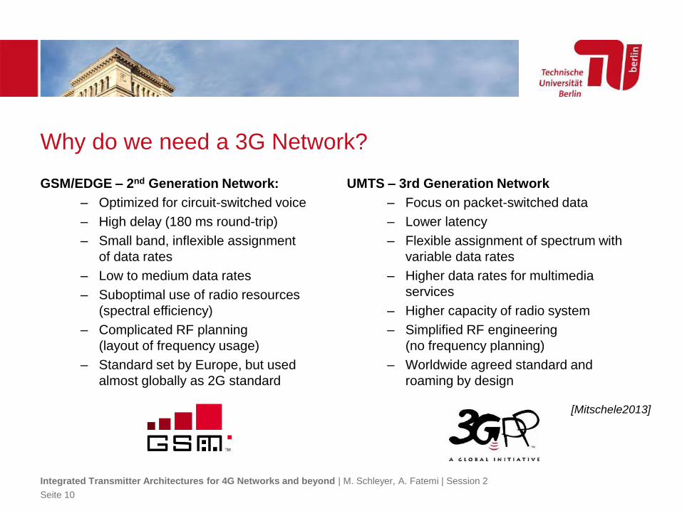
Why do we need a 3G Network?
GSM/EDGE – 2nd Generation Network:
– Optimized for circuit-switched voice
– High delay (180 ms round-trip)
– Small band, inflexible assignment
of data rates
– Low to medium data rates
– Suboptimal use of radio resources
(spectral efficiency)
– Complicated RF planning
(layout of frequency usage)
– Standard set by Europe, but used
almost globally as 2G standard
UMTS – 3rd Generation Network
– Focus on packet-switched data
– Lower latency
– Flexible assignment of spectrum with
variable data rates
– Higher data rates for multimedia
services
– Higher capacity of radio system
– Simplified RF engineering
(no frequency planning)
– Worldwide agreed standard and
roaming by design
Integrated Transmitter Architectures for 4G Networks and beyond | M. Schleyer, A. Fatemi | Session 2
Seite 10
[Mitschele2013]
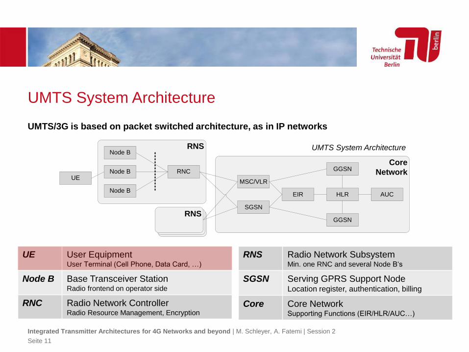
UMTS System Architecture
UMTS/3G is based on packet switched architecture, as in IP networks
Integrated Transmitter Architectures for 4G Networks and beyond | M. Schleyer, A. Fatemi | Session 2
Seite 11
UMTS System Architecture
UE User EquipmentUser Terminal (Cell Phone, Data Card, …)
Node B Base Transceiver StationRadio frontend on operator side
RNC Radio Network ControllerRadio Resource Management, Encryption
RNS Radio Network SubsystemMin. one RNC and several Node B‘s
SGSN Serving GPRS Support Node Location register, authentication, billing
Core Core NetworkSupporting Functions (EIR/HLR/AUC…)
RNSRNS
RNS
UE
Node B
Node B
Node B
RNC
Core
Network
SGSN
GGSN
HLREIR
MSC/VLR
AUC
GGSN
RNS
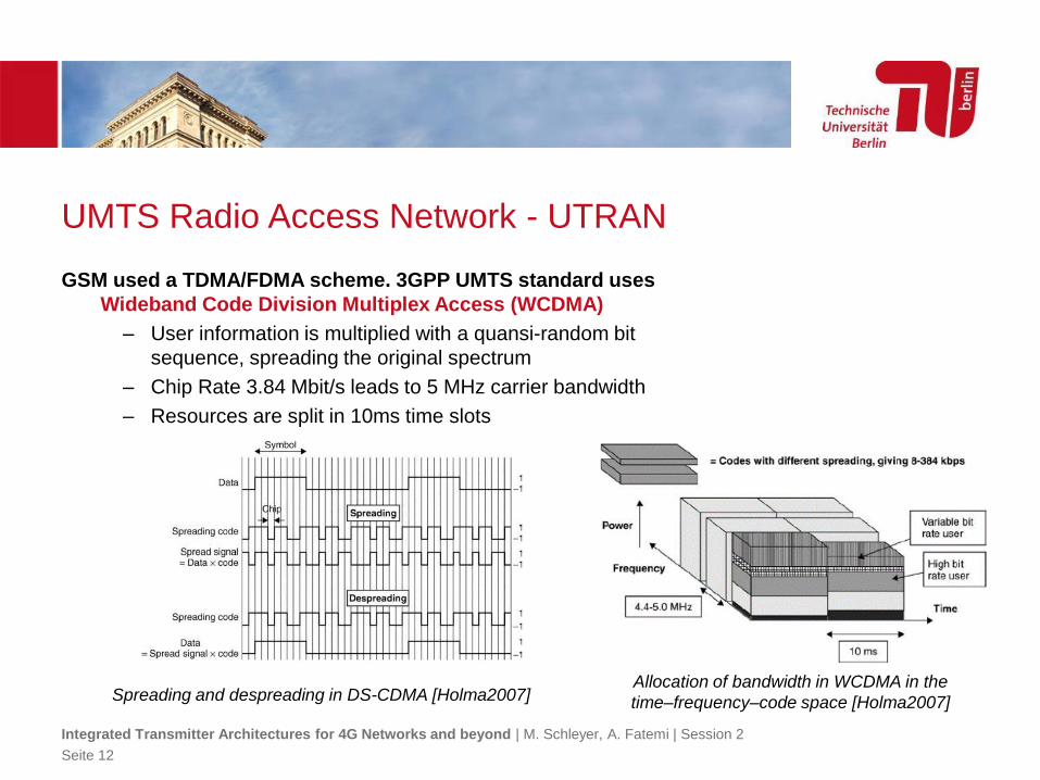
UMTS Radio Access Network - UTRAN
GSM used a TDMA/FDMA scheme. 3GPP UMTS standard uses
Wideband Code Division Multiplex Access (WCDMA)
– User information is multiplied with a quansi-random bit
sequence, spreading the original spectrum
– Chip Rate 3.84 Mbit/s leads to 5 MHz carrier bandwidth
– Resources are split in 10ms time slots
Integrated Transmitter Architectures for 4G Networks and beyond | M. Schleyer, A. Fatemi | Session 2
Seite 12
Allocation of bandwidth in WCDMA in the
time–frequency–code space [Holma2007]Spreading and despreading in DS-CDMA [Holma2007]
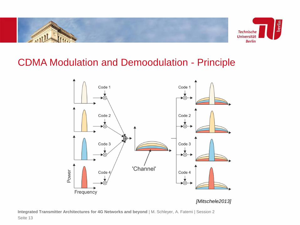
CDMA Modulation and Demoodulation - Principle
Integrated Transmitter Architectures for 4G Networks and beyond | M. Schleyer, A. Fatemi | Session 2
Seite 13
[Mitschele2013]
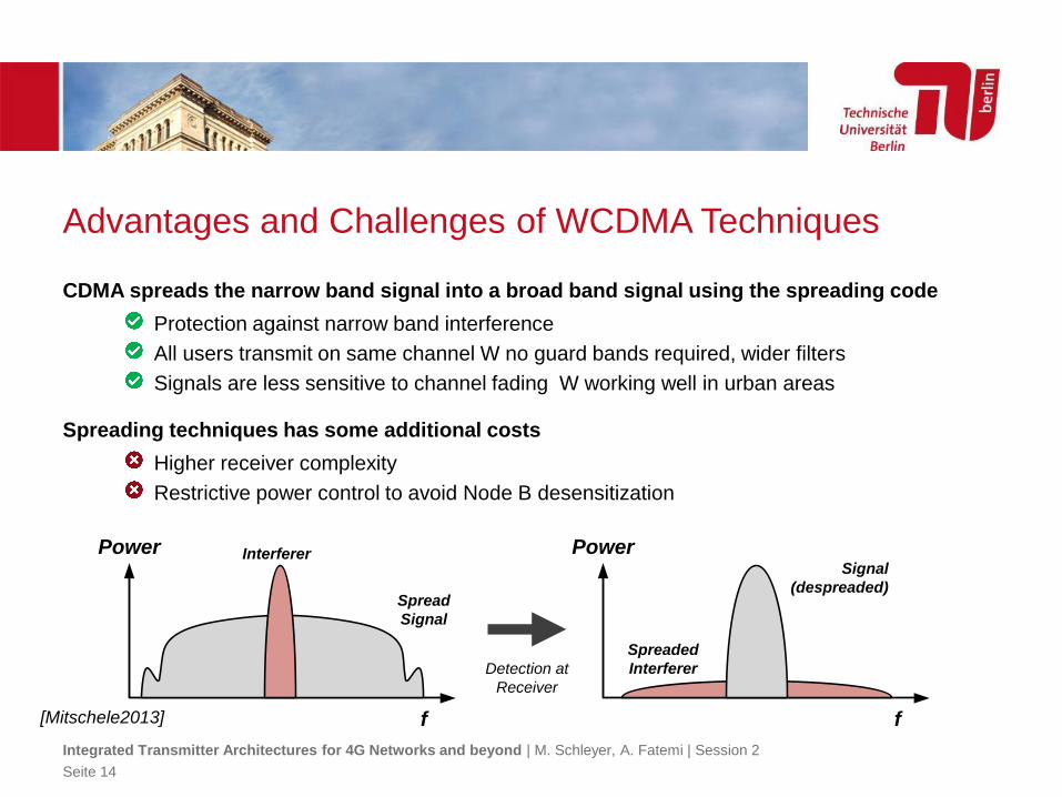
Advantages and Challenges of WCDMA Techniques
CDMA spreads the narrow band signal into a broad band signal using the spreading code
Protection against narrow band interference
All users transmit on same channel W no guard bands required, wider filters
Signals are less sensitive to channel fading W working well in urban areas
Spreading techniques has some additional costs
Higher receiver complexity
Restrictive power control to avoid Node B desensitization
Integrated Transmitter Architectures for 4G Networks and beyond | M. Schleyer, A. Fatemi | Session 2
Seite 14
f
Power Interferer
Spread
Signal
f
Power
Spreaded
Interferer
Signal
(despreaded)
Detection at
Receiver
[Mitschele2013]
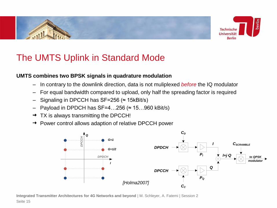
The UMTS Uplink in Standard Mode
UMTS combines two BPSK signals in quadrature modulation
– In contrary to the downlink direction, data is not muliplexed before the IQ modulator
– For equal bandwidth compared to upload, only half the spreading factor is required
– Signaling in DPCCH has SF=256 (≈ 15kBit/s)
– Payload in DPDCH has SF=4…256 (≈ 15…960 kBit/s)
TX is always transmitting the DPCCH!
Power control allows adaption of relative DPCCH power
Integrated Transmitter Architectures for 4G Networks and beyond | M. Schleyer, A. Fatemi | Session 2
Seite 15
DPDCH
DPCCH
I
Q
I+j⋅Q
CD
CSCRAMBLE
to QPSK
modulator
CC
PQ
PIDPDCH
DP
CC
H
G=1
G=1/2
I
Q
[Holma2007]
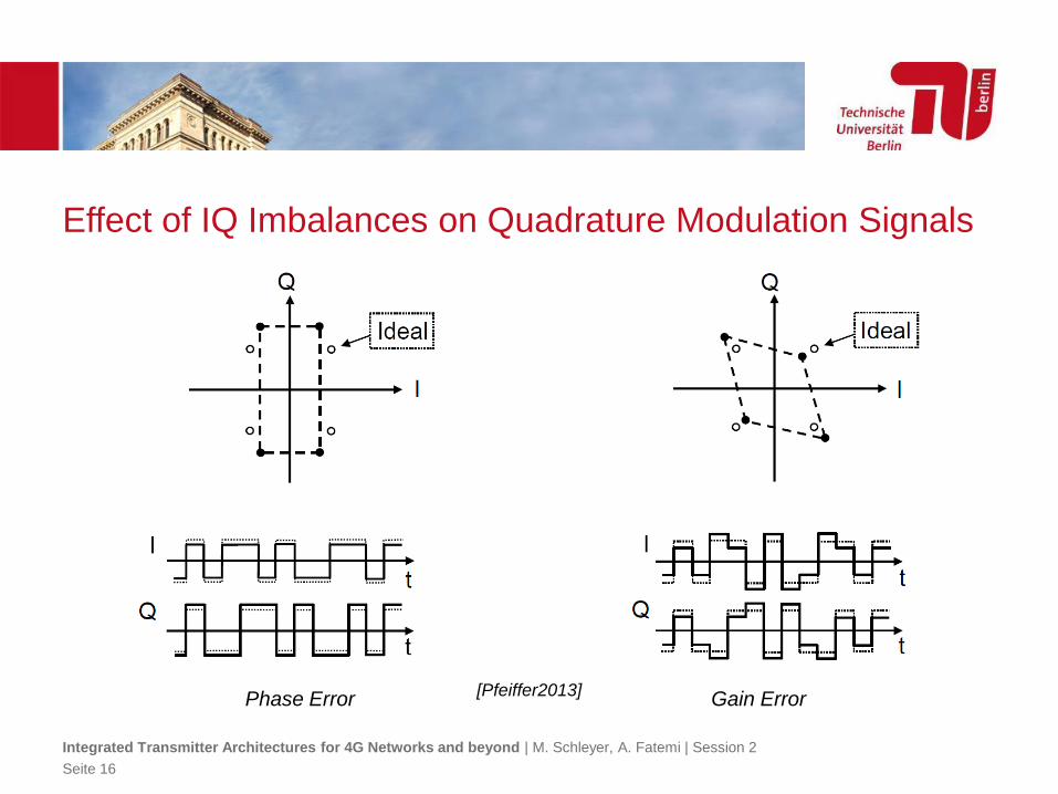
Effect of IQ Imbalances on Quadrature Modulation Signals
Phase Error Gain Error
Integrated Transmitter Architectures for 4G Networks and beyond | M. Schleyer, A. Fatemi | Session 2
Seite 16
[Pfeiffer2013]
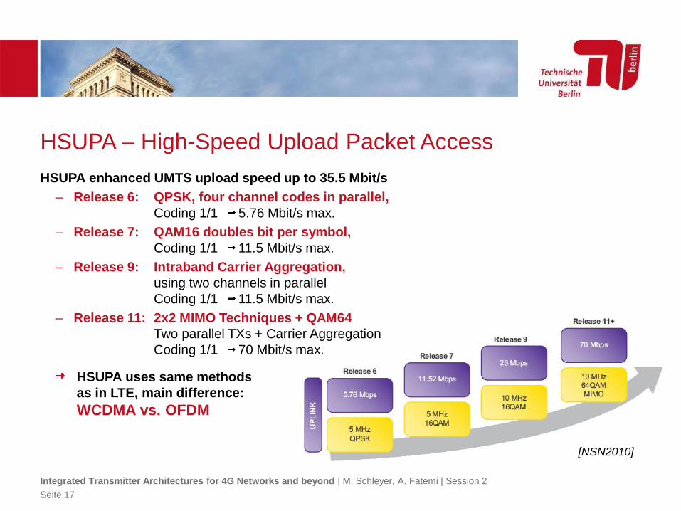
HSUPA – High-Speed Upload Packet Access
HSUPA enhanced UMTS upload speed up to 35.5 Mbit/s
– Release 6: QPSK, four channel codes in parallel,
Coding 1/1 5.76 Mbit/s max.
– Release 7: QAM16 doubles bit per symbol,
Coding 1/1 11.5 Mbit/s max.
– Release 9: Intraband Carrier Aggregation,
using two channels in parallel
Coding 1/1 11.5 Mbit/s max.
– Release 11: 2x2 MIMO Techniques + QAM64
Two parallel TXs + Carrier Aggregation
Coding 1/1 70 Mbit/s max.
HSUPA uses same methods
as in LTE, main difference:
WCDMA vs. OFDM
Integrated Transmitter Architectures for 4G Networks and beyond | M. Schleyer, A. Fatemi | Session 2
Seite 17
[NSN2010]
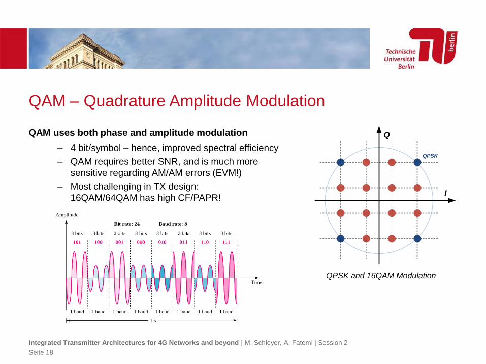
QAM – Quadrature Amplitude Modulation
QAM uses both phase and amplitude modulation
– 4 bit/symbol – hence, improved spectral efficiency
– QAM requires better SNR, and is much more
sensitive regarding AM/AM errors (EVM!)
– Most challenging in TX design:
16QAM/64QAM has high CF/PAPR!
Integrated Transmitter Architectures for 4G Networks and beyond | M. Schleyer, A. Fatemi | Session 2
Seite 18
QPSK
I
Q
QPSK and 16QAM Modulation
LTE AND LTE ADVANCED3GPP DATA SERVICES
Integrated Transmitter Architectures for 4G Networks and beyond | M. Schleyer, A. Fatemi | Session 2
Seite 19
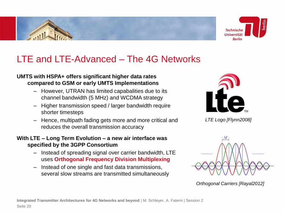
LTE and LTE-Advanced – The 4G Networks
UMTS with HSPA+ offers significant higher data rates
compared to GSM or early UMTS Implementations
– However, UTRAN has limited capabalities due to its
channel bandwidth (5 MHz) and WCDMA strategy
– Higher transmission speed / larger bandwidth require
shorter timesteps
– Hence, multipath fading gets more and more critical and
reduces the overall transmission accuracy
With LTE – Long Term Evolution – a new air interface was
specified by the 3GPP Consortium
– Instead of spreading signal over carrier bandwidth, LTE
uses Orthogonal Frequency Division Multiplexing
– Instead of one single and fast data transmissions,
several slow streams are transmitted simultaneously
Integrated Transmitter Architectures for 4G Networks and beyond | M. Schleyer, A. Fatemi | Session 2
Seite 20
Orthogonal Carriers [Rayal2012]
LTE Logo [Flynn2008]
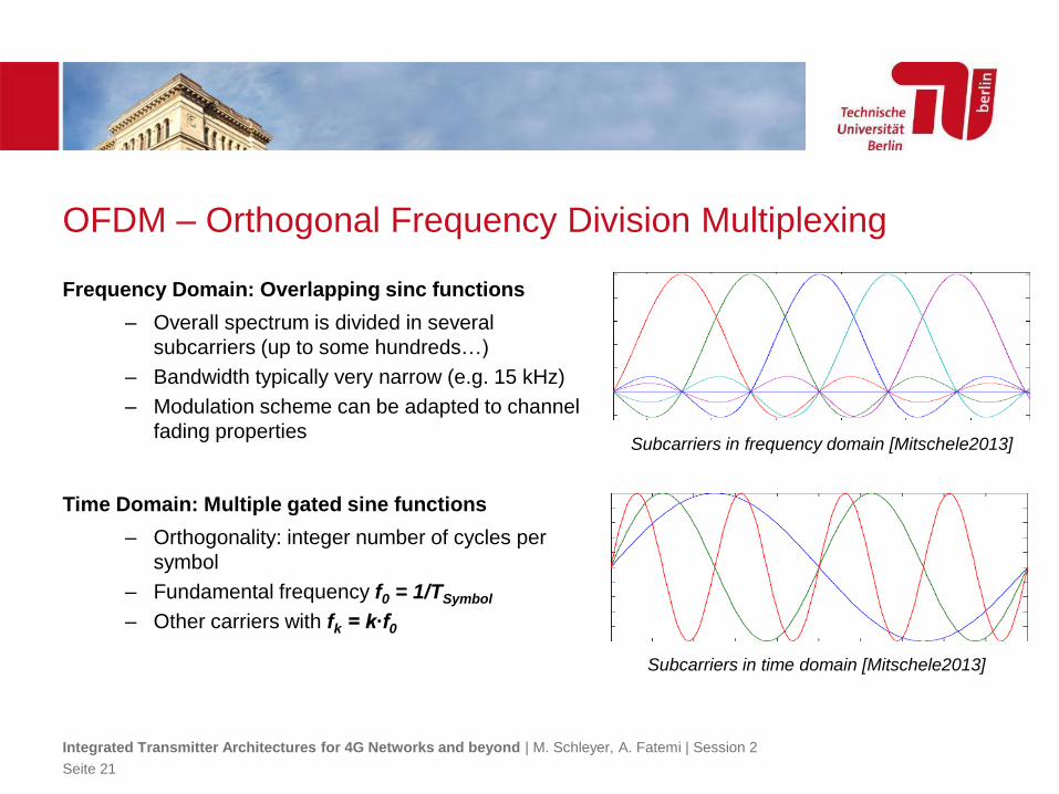
OFDM – Orthogonal Frequency Division Multiplexing
Frequency Domain: Overlapping sinc functions
– Overall spectrum is divided in several
subcarriers (up to some hundreds…)
– Bandwidth typically very narrow (e.g. 15 kHz)
– Modulation scheme can be adapted to channel
fading properties
Time Domain: Multiple gated sine functions
– Orthogonality: integer number of cycles per
symbol
– Fundamental frequency f0 = 1/TSymbol
– Other carriers with fk = k∙f0
Integrated Transmitter Architectures for 4G Networks and beyond | M. Schleyer, A. Fatemi | Session 2
Seite 21
Subcarriers in frequency domain [Mitschele2013]
Subcarriers in time domain [Mitschele2013]
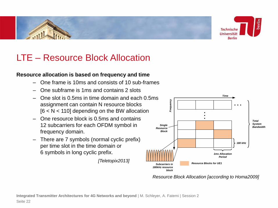
LTE – Resource Block Allocation
Resource allocation is based on frequency and time
– One frame is 10ms and consists of 10 sub-frames
– One subframe is 1ms and contains 2 slots
– One slot is 0.5ms in time domain and each 0.5ms
assignment can contain N resource blocks
[6 < N < 110] depending on the BW allocation
– One resource block is 0.5ms and contains
12 subcarriers for each OFDM symbol in
frequency domain.
– There are 7 symbols (normal cyclic prefix)
per time slot in the time domain or
6 symbols in long cyclic prefix. 1ms Allocation
Period
180 kHz
Total
System
Bandwidth
Resource Blocks for UE1
Single
Resource
Block
Subcarriers in
180kHz resource
block
Time
Fre
qu
en
cy
Integrated Transmitter Architectures for 4G Networks and beyond | M. Schleyer, A. Fatemi | Session 2
Seite 22
Resource Block Allocation [according to Homa2009]
[Teletopix2013]
LTE Uplink – Single-carrier FDMA
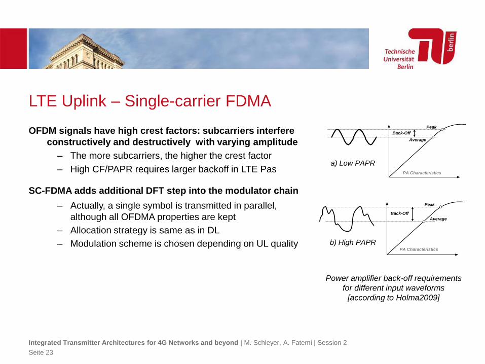
OFDM signals have high crest factors: subcarriers interfere
constructively and destructively with varying amplitude
– The more subcarriers, the higher the crest factor
– High CF/PAPR requires larger backoff in LTE Pas
SC-FDMA adds additional DFT step into the modulator chain
– Actually, a single symbol is transmitted in parallel,
although all OFDMA properties are kept
– Allocation strategy is same as in DL
– Modulation scheme is chosen depending on UL quality
Peak
Average
Back-Off
PA Characteristics
Integrated Transmitter Architectures for 4G Networks and beyond | M. Schleyer, A. Fatemi | Session 2
Seite 23
Peak
Average
Back-Off
PA Characteristics
Power amplifier back-off requirements
for different input waveforms
[according to Holma2009]
a) Low PAPR
b) High PAPR
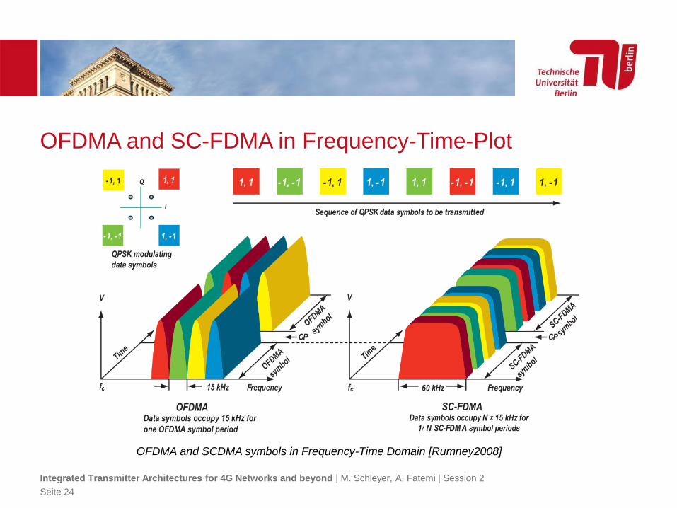
OFDMA and SC-FDMA in Frequency-Time-Plot
Integrated Transmitter Architectures for 4G Networks and beyond | M. Schleyer, A. Fatemi | Session 2
Seite 24
OFDMA and SCDMA symbols in Frequency-Time Domain [Rumney2008]
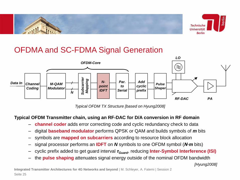
OFDMA and SC-FDMA Signal Generation
Typical OFDM Transmitter chain, using an RF-DAC for D/A conversion in RF domain
– channel coder adds error correcting code and cyclic redundancy check to data
– digital baseband modulator performs QPSK or QAM and builds symbols of m bits
– symbols are mapped on subcarriers according to resource block allocation
– signal processor performs an IDFT on N symbols to one OFDM symbol (N∙m bits)
– cyclic prefix added to get guard interval τGuard, reducing Inter-Symbol Interference (ISI)
– the pulse shaping attenuates signal energy outside of the nominal OFDM bandwidth
Integrated Transmitter Architectures for 4G Networks and beyond | M. Schleyer, A. Fatemi | Session 2
Seite 25
Typical OFDM TX Structure [based on Hyung2008]
[Hyung2008]
Par.
to
Serial
Add
cyclic
prefix
N-
point
IDFT
M-QAM
Modulator
RF-DAC PA
LO
Data In Pulse
Shaper
Channel
Coding
OFDM-Core
Su
bc
arr
ier
Ma
pp
ing
N
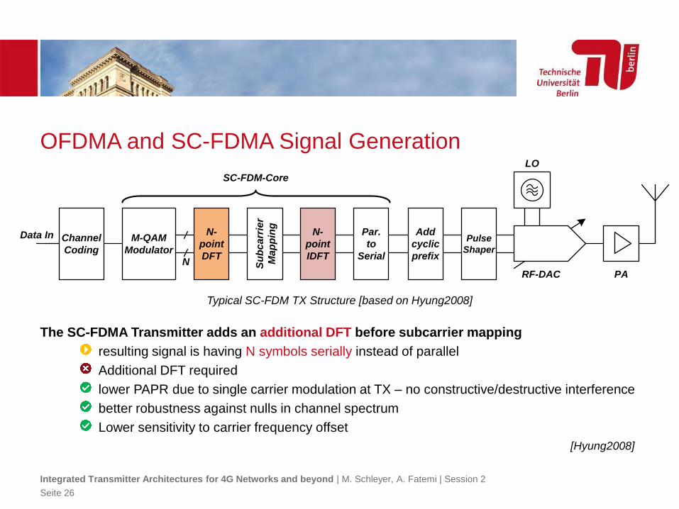
OFDMA and SC-FDMA Signal Generation
The SC-FDMA Transmitter adds an additional DFT before subcarrier mapping
resulting signal is having N symbols serially instead of parallel
Additional DFT required
lower PAPR due to single carrier modulation at TX – no constructive/destructive interference
better robustness against nulls in channel spectrum
Lower sensitivity to carrier frequency offset
Integrated Transmitter Architectures for 4G Networks and beyond | M. Schleyer, A. Fatemi | Session 2
Seite 26
Typical SC-FDM TX Structure [based on Hyung2008]
[Hyung2008]
Par.
to
Serial
Add
cyclic
prefix
N-
point
IDFT
M-QAM
Modulator
RF-DAC PA
LO
Data In Pulse
Shaper
Channel
Coding
SC-FDM-Core
Su
bc
arr
ier
Ma
pp
ing
N
N-
point
DFT
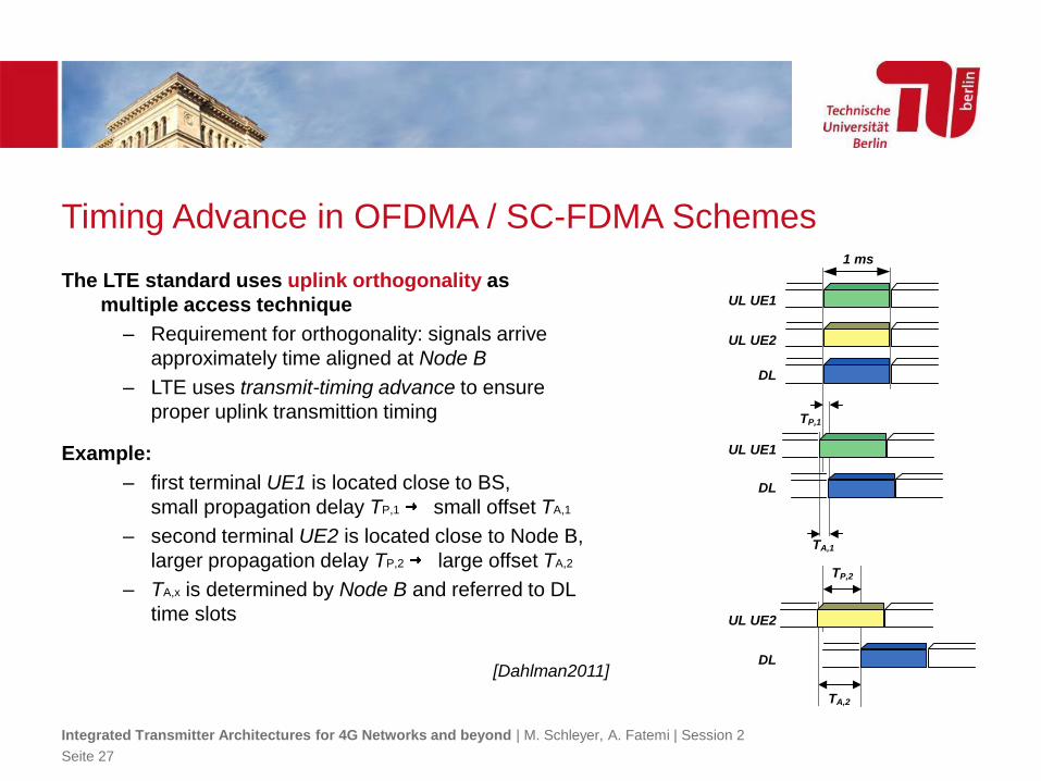
Timing Advance in OFDMA / SC-FDMA Schemes
The LTE standard uses uplink orthogonality as
multiple access technique
– Requirement for orthogonality: signals arrive
approximately time aligned at Node B
– LTE uses transmit-timing advance to ensure
proper uplink transmittion timing
Example:
– first terminal UE1 is located close to BS,
small propagation delay TP,1 small offset TA,1
– second terminal UE2 is located close to Node B,
larger propagation delay TP,2 large offset TA,2
– TA,x is determined by Node B and referred to DL
time slots
Integrated Transmitter Architectures for 4G Networks and beyond | M. Schleyer, A. Fatemi | Session 2
Seite 27
[Dahlman2011]
TP,2
TA,2
UL UE2
DL
TA,1
TP,1
UL UE1
DL
1 ms
UL UE1
UL UE2
DL
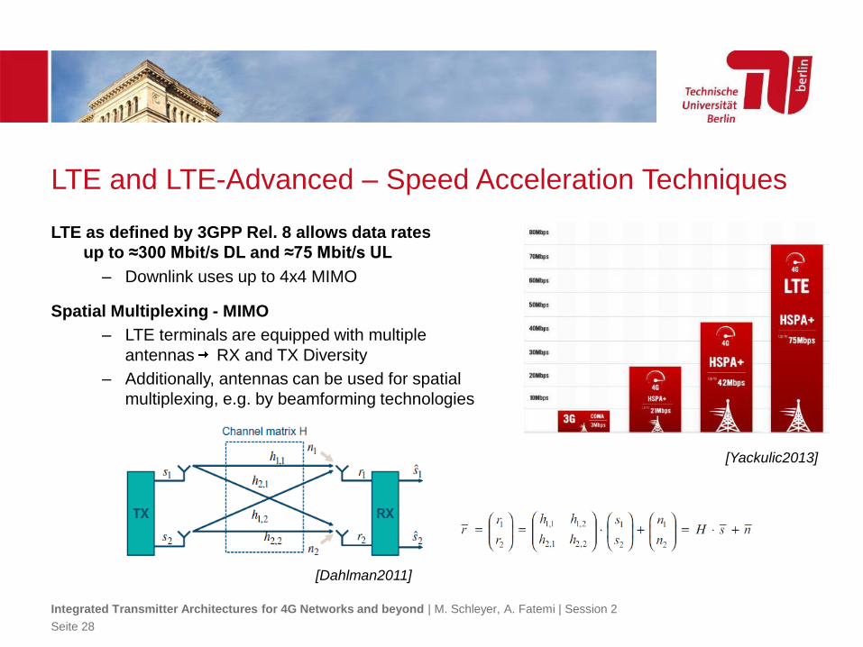
LTE and LTE-Advanced – Speed Acceleration Techniques
LTE as defined by 3GPP Rel. 8 allows data rates
up to ≈300 Mbit/s DL and ≈75 Mbit/s UL
– Downlink uses up to 4x4 MIMO
Spatial Multiplexing - MIMO
– LTE terminals are equipped with multiple
antennas RX and TX Diversity
– Additionally, antennas can be used for spatial
multiplexing, e.g. by beamforming technologies
Integrated Transmitter Architectures for 4G Networks and beyond | M. Schleyer, A. Fatemi | Session 2
Seite 28
[Yackulic2013]
[Dahlman2011]
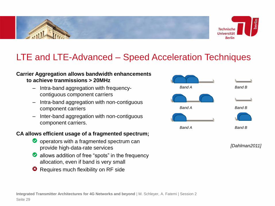
LTE and LTE-Advanced – Speed Acceleration Techniques
Carrier Aggregation allows bandwidth enhancements
to achieve tranmissions > 20MHz
– Intra-band aggregation with frequency-
contiguous component carriers
– Intra-band aggregation with non-contiguous
component carriers
– Inter-band aggregation with non-contiguous
component carriers.
CA allows efficient usage of a fragmented spectrum;
operators with a fragmented spectrum can
provide high-data-rate services
allows addition of free “spots” in the frequency
allocation, even if band is very small
Requires much flexibility on RF side
Integrated Transmitter Architectures for 4G Networks and beyond | M. Schleyer, A. Fatemi | Session 2
Seite 29
[Dahlman2011]
Band A Band B
Band A Band B
Band A Band B
Sources and Literature
[Agilent2005] Agilent Technologies, I.: EGPRS Test: Meeting
the Challenge of 8PSK Modulation, Online,
2005
[Dahlman2011] Dahlman, E.; Parkvall, S. & Skold, J.: 4G:
LTE/LTE-Advanced for Mobile Broadband:
Academic Press., 2011
[Flynn2008] Flynn, K.: 3GPP Marketing and
Communications Plan, Presentation at 3GPP
PCG #21, 2008
[Mitschele2013]Mitschele-Thiel, A. & Mückenheim, J.: Cellular
Communication Systems, Lecture Notes, 2013
[Myung2008a] Myung, H. G.: Single Carrier FDMA Tutorial,
Presentation, 2008
[Myung2008] Myung, H. G. & Goodman, D.: Single Carrier
FDMA: A New Air Interface for Long Term
Evolution (Wireless Communications and
Mobile Computing): Wiley., 2008
[Rayal2012] Rayal, F.: The Number of Sub-Carriers in
OFDM impacts NLOS Backhaul Performance
(More than You Think), Online, 2012
[Rumney2008] Rumney, M.: 3GPP LTE: Introducing Single-
Carrier FDMA. In: Agilent Measurement Journal
(2008), Nr. 4, S. 18-27
[Teletopix2013] Teletopix: LTE Frame Structure and Resource
Block Architecture, 2013
[Walke2003] Walke, B. H.; Seidenberg, P. & Althoff, M. P.:
UMTS: The Fundamentals: Wiley., 2003
[Wiki2007] Wikipedia: QPSK Timing Diagramm,
[Yackulic2013] Yackulic, C.: 4G – is it working?, Online, 2013
[Holma2009] LTE for UMTS - OFDMA and SC-FDMA Based
Radio Access. In: Holma, H. & Toskala, A.
(Hrsg.): Wiley., 2009
[Holma2007] WCDMA for UMTS: HSPA Evolution and LTE.
In: Holma, H. & Toskala, A. (Hrsg.): Wiley.,
2007
[Wiki2007a] Bit-error rate curves for phase-shift keying:
BPSK, QPSK, 8-PSK and 16-PSK, 2007
Integrated Transmitter Architectures for 4G Networks and beyond | M. Schleyer, A. Fatemi | Session 2
Seite 30
Summary
Cellular communications has its roots at the early 1900
– Starting with Marconi‘s telegraphy aparatus, radio communication further evolved
– In the 1960‘s to 1990‘s, analog and hybrid 1G networks were publically available
– The interoperable GSM paved the to road what we have in our pockets today
With digital power and analog integration, capabilites of cellular networks grew
– First „handsets“ actually filled a whole car booth
– With microprocessors, digitally assists networks grew and allowed cellular concepts (AMPS)
– Starting with GSM and EDGE, data services enhanced the user experience
Each evolutional step brought new requirements to RF design
– From analog modulation to burst oriented GMSK…
– …ending with high PAPR schemes as 8PSK, 16QAM, 32QAM
Next Week: Basics of RF Power Amplifier
A Class E Power Amplifier Design in RFCMOS technology
Integrated Transmitter Architectures for 4G Networks and beyond | M. Schleyer, A. Fatemi | Session 2
Seite 31