integrated refrigeration and storage for advanced liquid
TRANSCRIPT

1
Integrated Refrigeration and Storage for Advanced Liquid Hydrogen Operations
A. M. Swanger1, W. U. Notardonato2, W. L. Johnson3, T. M. Tomsik3
1 NASA Kennedy Space Center, Cryogenics Test Laboratory, NE-M5,
KSC, FL 32899 USA 2 NASA Kennedy Space Center, Cryogenics Test Laboratory, UB-R1,
KSC, FL 32899 USA 3 NASA Glenn Research Center, Fluid and Cryogenic Systems Branch, LTF,
Cleveland, OH 44135 USA
ABSTRACT
NASA has used liquefied hydrogen (LH2) on a large scale since the beginning of the space
program as fuel for the Centaur and Apollo upper stages, and more recently to feed the three
space shuttle main engines. The LH2 systems currently in place at the Kennedy Space Center
(KSC) launch pads are aging and inefficient compared to the state-of-the-art. Therefore, the
need exists to explore advanced technologies and operations that can drive commodity costs
down, and provide increased capabilities. The Ground Operations Demonstration Unit for Liquid
Hydrogen (GODU-LH2) was developed at KSC to pursue these goals by demonstrating active
thermal control of the propellant state by direct removal of heat using a cryocooler. The project
has multiple objectives including zero loss storage and transfer, liquefaction of gaseous
hydrogen, and densification of liquid hydrogen. The key technology challenge was efficiently
integrating the cryogenic refrigerator into the LH2 storage tank. A Linde LR1620 Brayton cycle
refrigerator is used to produce up to 900W cooling at 20K, circulating approximately 22 g/s
gaseous helium through the hydrogen via approximately 300 m of heat exchanger tubing.
The GODU-LH2 system is fully operational, and is currently under test. This paper will
discuss the design features of the refrigerator and storage system, as well as the current test
results.
INTRODUCTION
In the 1960s NASA drove a great deal of large scale liquid hydrogen technology
development in preparation for the Apollo moon missions, and continued to be one of the largest
consumers of LH2 through the end of the Space Shuttle program in 2011. In the 50 years since
this early period of innovation however, the state-of-the-art in cryogenic systems has transitioned
to industry, and NASA has found itself utilizing inefficient equipment. Over the duration of the
Space Shuttle program NASA lost approximately 50% of the hydrogen purchased due to
continuous heat leak into ground and flight vessels, transient cool-down of warm cryogenic
equipment, boil-off during transport, liquid bleeds, and vent losses [1]. Since production of
liquid hydrogen is an energy intensive process, these losses constituted a large, unrecoverable
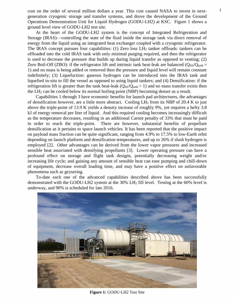
2 cost on the order of several million dollars a year. This cost caused NASA to invest in next-
generation cryogenic storage and transfer systems, and drove the development of the Ground
Operations Demonstration Unit for Liquid Hydrogen (GODU-LH2) at KSC. Figure 1 shows a
ground level view of GODU-LH2 test site.
At the heart of the GODU-LH2 system is the concept of Integrated Refrigeration and
Storage (IRAS)—controlling the state of the fluid inside the storage tank via direct removal of
energy from the liquid using an integrated heat exchanger coupled with a cryogenic refrigerator.
The IRAS concept pursues four capabilities: (1) Zero loss LH2 tanker offloads: tankers can be
offloaded into the cold IRAS tank with only minimal purging required, and then the refrigerator
is used to decrease the pressure that builds up during liquid transfer as opposed to venting; (2)
Zero Boil-Off (ZBO): if the refrigerator lift and intrinsic tank heat-leak are balanced (Qlift/Qtank =
1) and no mass is being added or removed then the pressure and liquid level will remain constant
indefinitely; (3) Liquefaction: gaseous hydrogen can be introduced into the IRAS tank and
liquefied in-situ to fill the vessel as opposed to using liquid tankers; and (4) Densification: if the
refrigeration lift is greater than the tank heat-leak (Qlift/Qtank > 1) and no mass transfer exists then
the LH2 can be cooled below its normal boiling point (NBP) becoming denser as a result.
Capabilities 1 through 3 have economic benefits for launch pad architectures, the advantages
of densification however, are a little more abstract. Cooling LH2 from its NBP of 20.4 K to just
above the triple-point of 13.9 K yields a density increase of roughly 9%, yet requires a hefty 3.8
kJ of energy removal per liter of liquid. And this required cooling becomes increasingly difficult
as the temperature decreases, resulting in an additional Carnot penalty of 33% that must be paid
in order to reach the triple-point. There are however, substantial benefits of propellant
densification as it pertains to space launch vehicles. It has been reported that the positive impact
on payload mass fraction can be quite significant, ranging from 4.9% to 17.5% to low-Earth orbit
depending on launch platform and densification temperatures, and up to 26% if slush hydrogen is
employed [2]. Other advantages can be derived from the lower vapor pressures and increased
sensible heat associated with densifying propellants [3]. Lower operating pressure can have a
profound effect on storage and flight tank designs, potentially decreasing weight and/or
increasing life cycle; and gaining any amount of sensible heat can ease pumping and chill-down
of equipment, decrease overall loading time, and may have a positive effect on unfavorable
phenomena such as geysering.
To-date each one of the advanced capabilities described above has been successfully
demonstrated with the GODU-LH2 system at the 30% LH2 fill level. Testing at the 60% level is
underway, and 90% is scheduled for late 2016.
Figure 1: GODU-LH2 Test Site
3
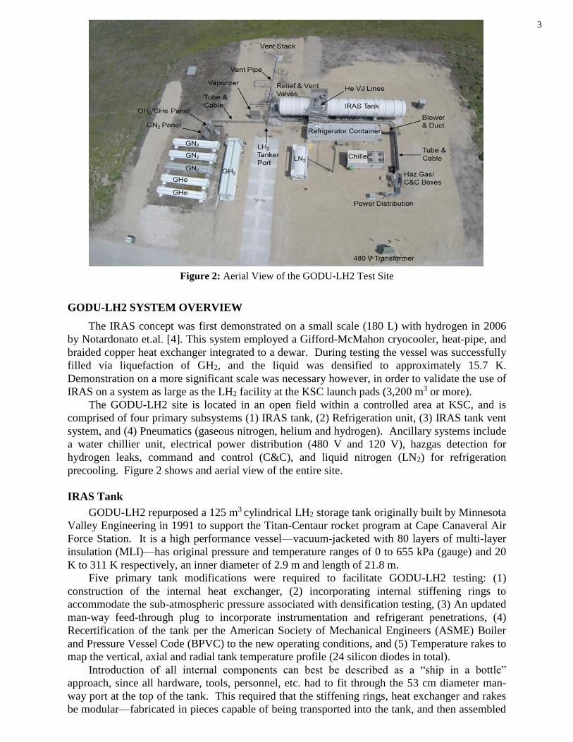
Figure 2: Aerial View of the GODU-LH2 Test Site
GODU-LH2 SYSTEM OVERVIEW
The IRAS concept was first demonstrated on a small scale (180 L) with hydrogen in 2006
by Notardonato et.al. [4]. This system employed a Gifford-McMahon cryocooler, heat-pipe, and
braided copper heat exchanger integrated to a dewar. During testing the vessel was successfully
filled via liquefaction of GH2, and the liquid was densified to approximately 15.7 K.
Demonstration on a more significant scale was necessary however, in order to validate the use of
IRAS on a system as large as the LH2 facility at the KSC launch pads (3,200 m3 or more).
The GODU-LH2 site is located in an open field within a controlled area at KSC, and is
comprised of four primary subsystems (1) IRAS tank, (2) Refrigeration unit, (3) IRAS tank vent
system, and (4) Pneumatics (gaseous nitrogen, helium and hydrogen). Ancillary systems include
a water chillier unit, electrical power distribution (480 V and 120 V), hazgas detection for
hydrogen leaks, command and control (C&C), and liquid nitrogen (LN2) for refrigeration
precooling. Figure 2 shows and aerial view of the entire site.
IRAS Tank
GODU-LH2 repurposed a 125 m3 cylindrical LH2 storage tank originally built by Minnesota
Valley Engineering in 1991 to support the Titan-Centaur rocket program at Cape Canaveral Air
Force Station. It is a high performance vessel—vacuum-jacketed with 80 layers of multi-layer
insulation (MLI)—has original pressure and temperature ranges of 0 to 655 kPa (gauge) and 20
K to 311 K respectively, an inner diameter of 2.9 m and length of 21.8 m.
Five primary tank modifications were required to facilitate GODU-LH2 testing: (1)
construction of the internal heat exchanger, (2) incorporating internal stiffening rings to
accommodate the sub-atmospheric pressure associated with densification testing, (3) An updated
man-way feed-through plug to incorporate instrumentation and refrigerant penetrations, (4)
Recertification of the tank per the American Society of Mechanical Engineers (ASME) Boiler
and Pressure Vessel Code (BPVC) to the new operating conditions, and (5) Temperature rakes to
map the vertical, axial and radial tank temperature profile (24 silicon diodes in total).
Introduction of all internal components can best be described as a “ship in a bottle”
approach, since all hardware, tools, personnel, etc. had to fit through the 53 cm diameter man-
way port at the top of the tank. This required that the stiffening rings, heat exchanger and rakes
be modular—fabricated in pieces capable of being transported into the tank, and then assembled

4 by hand. All modifications were performed by KSC personnel in 2013, and were covered
extensively by Swanger et.al. [5,6].
Design of the internal heat exchanger is highly 3-dimensinal in order to effectively
distribute the cold helium refrigerant throughout the tank volume, and provide some structural
rigidity. It consists of supply and return manifolds (total of 37 m of 25 mm OD tubing, and
located at the 25% and 75% fill levels respectively), 40 cooling coils (total of 244 m of 6.4 mm
OD tubing), and has a total heat transfer area of approximately 11 m2. Refrigerant flows were
balanced end-to-end using precision orifice fittings as previously reported by Fesmire et.al. [7].
Two 25 mm diameter by 3 m long flexible lines connect to the man-way feedthrough to each
manifold. Each of these tubing sections had to be interfaced using fittings with ultra-low leak
rates, and high reliability. Swagelok VCR type units with silver-plated nickel gaskets and
retainer rings were chosen for this task. Figure 3 shows the as-built internal IRAS configuration
with heat exchanger, stiffening rings, and temperature rakes.
Figure 3: Internal IRAS Tank Modifications
Figure 4: Refrigeration Container Showing the Refrigerator Module (foreground) and RSX Compressor
(background) (left); GHe VJ Piping Interfaced to IRAS Tank (right)
Cold
Helium
Return
Manifold
Cold
Helium
Supply
Manifold
Cooling
Coils
Stiffening
Ring
Temp
Rake

5 Refrigeration System
The cryocooler selected for the GODU-LH2 system is a Linde LR1620 model with an RSX
helium compressor. This reverse-Brayton cycle refrigerator employs two parallel piston
expanders with 4-stages of recuperation, and can officially provide 400 W lift at 20 K, or 850 W
with LN2 precooling at 22 g/s mass flow rate. However, initial performance testing yielded
elevated capacities of roughly 500 W and 900 W with and without precooling respectively.
Cold, ultra-high purity (UHP) helium from the refrigerator is routed to and from the IRAS tank
through 8.5 m (each way) of 25.4 mm x 63.5 mm vacuum-jacketed (VJ) hard piping.
During system conception it was estimated that the intrinsic heat leak of the retrofitted LH2
dewar was around 350 W. This yielded a refrigeration ratio (Qlift/Qtank) of 1.1 and 2.4 at the rated
lift capacities, with and without precooling respectively; and 1.4 and 2.6 using the actual system
performance numbers. As previously noted, a ratio greater than 1.0 was necessary to achieve all
the test objectives. Furthermore, a large positive margin afforded even greater test flexibility and
control by increasing system response.
Housing the refrigerator and compressor modules—equipment that does not comply with
the National Fire Protection Association (NFPA) requirements for operation in explosive gas
environments—in close proximity to the IRAS tank was achieved using a standard 12 m ISO
shipping container constantly purged with fresh air (outside the NFPA Class I, Division II area)
via a blower unit. Pressure inside the semi-sealed container is kept at roughly 0.5 inH2O above
atmospheric at all times when hydrogen was present in the tank to ensure that, in the case of a
leak, no GH2 could infiltrate the purged environment. Integrating the entire refrigeration system
into the shipping container also allowed for the possibility of transporting it to a future location
in an assembled, serviced state. Only the refrigerant supply and return lines, cooling water lines,
and power to the system must be de-mated prior to transporting.
Rejecting the heat of compression and cooling the compressor oil is accomplished via a
custom built chilled water unit that complies with NFPA regulations to operate within a Class I,
Division II zone. Similar to the refrigerator and compressor modules, this unit was built into an
ISO shipping container (6 m instead of 12 m), and can be easily transported. 25 mm diameter
PVC lines interface the chiller to the RSX compressor, and provides a constant supply of 16°C
water to the system. Figure 4 shows the refrigerator and compressor modules inside the shipping
container, and the VJ interface piping.
Liquid nitrogen for helium precooling is supplied from a 20,000 L US Department of
Transportation (DOT) approved transportable dewar placed adjacent to the refrigeration
container. It interfaces to the refrigerator module through 11 m of 13 mm x 51 mm VJ hard
piping. Pressure is allowed to build in the LN2 tank from natural boil-off, and is maintained
around 103 kPa by periodically venting the ullage space. While running in precooling mode the
internal Linde control software maintains a boiling LN2 pool inside the refrigerator using a bang-
bang control scheme. Incoming GHe from the compressor is partially routed through the LN2,
heat exchanger, dropping its temperature close to the LN2 boiling point before being fed back
into the recouperators. Boil-off vapor is vented to atmosphere out the side of the refrigeration
container. Use of LN2 in this manner accounts for the 400 W increase in refrigeration capacity
over the standard closed-loop cycle.
Control of the lift capacity is accomplished by adding heat to the cold GHe exiting the
piston expanders via an in-line resistive heater. An exit or return temperature set point can be
entered into the standard Linde software, which in turn adds heat as required. Custom software
was also developed for GODU-LH2 that interfaces with the Linde package, and controls the
heater to achieve a desired IRAS tank pressure.
IRAS Vent System & Pneumatics
The IRAS tank vent system was designed to meet the unique test requirements of the
GODU-LH2 project, as well as those established in the ASME BPVC. Two vent paths can be
utilized depending on the mode of operation: A 150 mm line and 7 m tall vent stack
accommodates large vent rates, and routes flow from the relief devices in case of an over
6 pressurization event; and a 25 mm path directs normal boil-off flow to a 3 m tall stack during
IRAS tank heat leak testing, and when the refrigeration system is down for repair or
maintenance. Each of these legs ties into the 100 mm primary IRAS tank vent, and are activated
remotely from the command and control trailer. A vertical, open-air vaporizer is also employed
in the system to provide tank pressurization for possible future LH2 transfer testing. Since an
overarching theme of GODU-LH2 is to minimize, or completely eliminate, any hydrogen losses,
under normal operation the IRAS tank is isolated from the vent system, and the refrigerator is
used to control the pressure. During densification testing, when the tank is allowed to go sub-
atmospheric, any interface to the ullage space (flanges, valves, fittings, etc.) is “bagged” and
purged with gaseous helium. This is done as a precaution, in case a leak occurs helium instead
of air will be drawn into the tank.
To reduce project cost, several pneumatic panels and gas storage bottles were reused from
the Space Shuttle program to provide gaseous helium, hydrogen and nitrogen to the system. Two
16.5 MPa movable storage units (MSU) provide a 2,265 m3 helium storage capability, and three
additional 16.5 MPa MSUs store up to 3,400 m3 of gaseous nitrogen.. The facility nitrogen panel
reduces the 16.5 MPa down to several 5 MPa sources as well as up to twenty 700 kPa sources
used for valve actuation, panel inerting, and purging of lines. Gaseous hydrogen is supplied to
the site by compressed gas trailers, is regulated from 25.5 MPa down to 1,030 kPa and used for
liquefaction supply as well as purge and pressurization of lines and the IRAS tank [8].
GODU-LH2 TESTING RESULTS
The GODU-LH2 test matrix consists of three primary objectives (zero-loss offloading and
storage, liquefaction, and densification) conducted at three different IRAS tank fill levels (30%,
60%, and 90%). Measurable differences in system efficiency and response are expected at the
different fill levels as the internal heat exchanger becomes increasingly submerged in LH2.
Initial system start-up and testing began in March 2015 with an LN2 cold-shock of the IRAS
tank, followed by evacuation and GH2 purge cycles until the proper purity was achieved. The
refrigerator was then used to bring the inner tank wall temperature down to roughly 55 K in
order to facilitate a zero-loss tanker offload of approximately 45,000 L of LH2 (i.e. no hydrogen
was lost during the offload process), and afterward to re-condense the ullage vapor that
accumulated during the transfer [9].
This first tanker offload effectively brought the fill level to around 30%, and once the
pressure stabilized close to the NBP, testing to determine the intrinsic tank heat leak commenced.
Over a three week period the steady-state boil-off was measured using a Brooks Instruments
mass flow meter, and was determined to be 257 SLPM on average, at a tank pressure of 104.8
kPa (absolute). This equates to a heat leak of 292 W, and refrigeration ratios of 1.7 and 3.1 with
and without LN2 precooling within the refrigeration system. Once the heat leak was known the
refrigerator was started, IRAS tank brought online, and ZBO, liquefaction and densification
testing began.
Zero Boil-Off/Pressure Control
In order to demonstrate full control of the tank pressure with the GODU-LH2 software it
was desirable to test the response of the system when a set-point is chosen at both higher and
lower values than the tank pressure at that time—to converge to the desired pressure from
“above” and “below.” From above, the control logic has to allow the refrigerator to run at
maximum capacity in order to drop the pressure as fast as possible, and then introduce heat until
the refrigerator lift balances the tank heat leak (i.e. a refrigeration ratio of 1). Whereas, from
below, the software needs to create and refrigeration ratio less than 1 by introducing excessive
heat into the tank in order to drive the pressure up to the set-point. This test sequence was
performed over a 9 day period, using four different set-points, and without LN2 precooling for
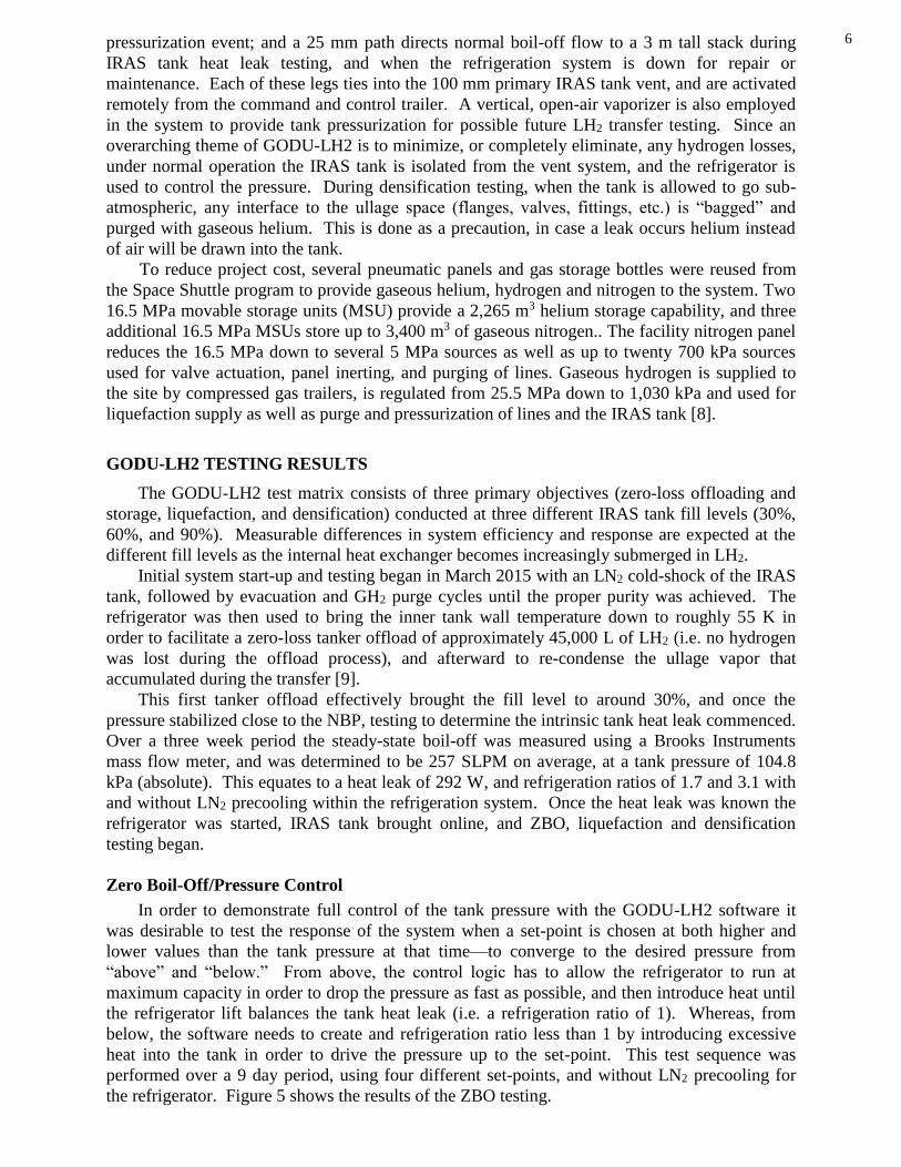
the refrigerator. Figure 5 shows the results of the ZBO testing.

7 Figure 5 shows that the system is able to control the tank pressure very precisely, and has a
relatively fast response time for a large ullage volume. It is apparent from the transient periods
that the system responds faster when approaching the set-point pressure from below rather than
above. From above, the average slope is roughly 0.5 kPa/hr, and from below it is 1.4 kPa/hr. On
average the tank pressure was 0.35 kPa below the set-point, attributed to PID loop tuning, and
the average standard deviation over the duration of time for set points 1, 2 and 3 was only 0.07
kPa. As expected, the tank temperatures trended with the pressure and show a small, but obvious
amount of ullage stratification, save the inversion of the bottom two readings seen at roughly 40
hours. This anomaly is most likely due to the proximity of the liquid-vapor interface at the 30%
fill level to the bottom manifold of the heat exchanger. The top most ullage temperature line in
Figure 5 is located 2 m from the inner tank floor, just below the top manifold, while the lowest
line (labeled as the “liquid temperature”) is 0.6 m from the floor, just below the bottom manifold,
and is completely submerged at the reported fill level. The location of the other four temperature
readings are spaced evenly between these two.
Hydrogen Liquefaction
Liquefaction testing at the 30% fill level was conducted over a day and a half period and
consisted of feeding gaseous hydrogen from a mobile compressed gas trailer to a Brooks
Instruments mass flow controller, which fed directly into the IRAS tank via the vent line. The
refrigerator was operated at full capacity (i.e. with LN2 precooling), and the control logic
managed the mass flow in order to achieve a constant tank pressure.
It must be stated that due to budget constraints the GODU-LH2 system in its current
configuration is not optimized to conduct hydrogen liquefaction. Feeding ambient temperature
GH2 directly into the tank is not the preferred method due the non-trivial ortho-to-para energy
penalty that must be paid. As a result, the GODU-LH2 liquefaction testing is aimed more at
validating the ability of IRAS to liquefy on a large scale, and testing the software control
schemes, rather than maximizing the liquid yield. To these ends 30% testing was successful.
The control logic maintained a constant tank pressure using the mass flow controller, and the
increase in liquid volume was captured by the liquid level sensor via a ΔP reading.
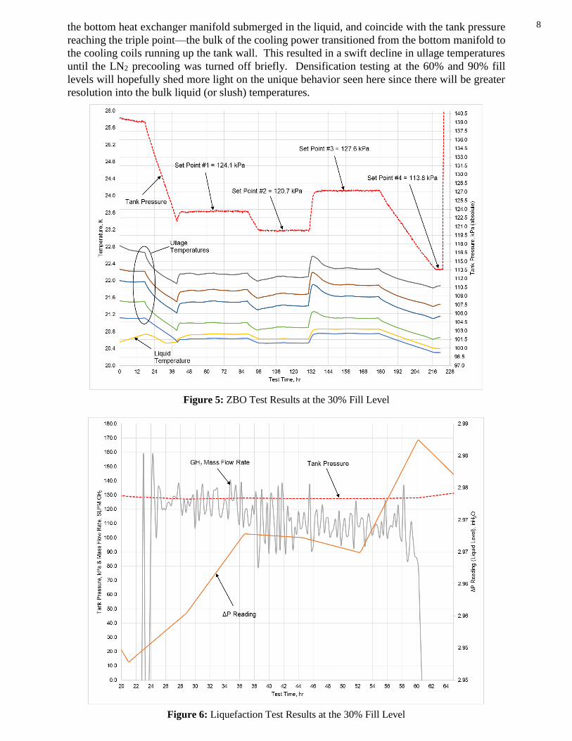
Figure 6 shows the results of the liquefaction testing. The average tank pressure during
liquefaction was 127.6 kPa, with a standard deviation between hour 26 and 58 of 0.2 kPa.
Average GH2 mass flow rate was 113.6 SLPM, and the head pressure increase (ΔP reading) was
0.02 inH2O. In all, roughly 295 L of liquid was produced during the 30% testing.
Hydrogen Densification
Densification testing officially began when the tank pressure went sub-atmospheric and the
liquid hydrogen dropped below its normal boiling point of 20.4 K. The refrigerator was run at
full power, and successfully densified the LH2 for roughly 14 days prior to a component failure
and subsequent shutdown. Figure 7 shows the temperature and pressure data from the 30%
densification testing.
Many notable features can be seen in figure 7, most obvious is the minimum temperature
reported by many of the diodes. Values well below the triple point were seen not only in the
bulk liquid, but also in the vapor space a significant distance from the liquid-vapor interface, the
farthest being approximately 0.6 m away. This result is not completely understood at this time.
It implies that not only was a significant amount of solid hydrogen being formed inside the IRAS
tank, but that it was somehow also being cooled below its freezing point. Preliminary
calculations estimate that roughly 1,134 kg of hydrogen ice was produced during the test, and it
is believed that it existed as a homogenous bulk slush mixture as opposed to solid formations
clinging to the cold heat exchanger surfaces. The minimum temperature witnessed during the
test was 12.6 K; a full degree below the triple point value.
Another interesting feature is the sharp dip in ullage temperatures seen around hour 260, at
the same time the tank pressure appears to reach the triple point. This is not believed to be a
coincidence. Instead, when solid hydrogen began to form—which would take place mostly at
8 the bottom heat exchanger manifold submerged in the liquid, and coincide with the tank pressure
reaching the triple point—the bulk of the cooling power transitioned from the bottom manifold to
the cooling coils running up the tank wall. This resulted in a swift decline in ullage temperatures
until the LN2 precooling was turned off briefly. Densification testing at the 60% and 90% fill
levels will hopefully shed more light on the unique behavior seen here since there will be greater
resolution into the bulk liquid (or slush) temperatures.
Figure 5: ZBO Test Results at the 30% Fill Level
Figure 6: Liquefaction Test Results at the 30% Fill Level

9
Figure 7: Densification Test Results at the 30% Fill Level
CONCLUSION
The GODU-LH2 system has successfully demonstrated zero-boil-off, liquefaction, and
densification of hydrogen in a 125 m3 tank at approximately 30% full using Integrated
Refrigeration and Storage (IRAS). Two un-vented tanker off-loads were also performed with no
liquid in the tank (the worst case scenario). Further demonstrations will repeat these at LH2 fill
levels of approximately 60% and 90%.
Initial results indicate that this type of IRAS system could be readily scaled to support space
launch vehicle and pad operations by lowering the cost of cryogenic propellant maintenance,
affording greater flexibility for propellant handling, and providing increased mission capability.
REFERENCES
1. Partridge, J. K., “Fractional consumption of liquid hydrogen and liquid oxygen during the space
shuttle program”, Advances in Cryogenic Engineering, AIP Conference Proceedings, Vol.1434,
pp.1765-1770 (2012).
2. Haberbusch, M. S., “Study Task for Determining the Effects of Boost-Phase Environments on
Densified Propellants Thermal Conditions for Expendable Launch Vehicles”, NASA/CR—2002-
210808, (2002)
3. Mustafi, S., Johnson, W., Kashani, A., Jurns, J., Kutter, B., Daniel, K., and Shull, J., “Subcooling for
Long Duration In-Space Cryogenic Propellant Storage”, Proceedings of the AIAA SPACE 2010
Conference & Exposition, California, Anaheim, (2010), AIAA 2010-8869
4. Notardonato, W.U., Baik, J.H., McIntosh, G.E., “Operational testing of densified hydrogen using G-
M refrigeration”, Advances in Cryogenic Engineering, AIP Conference Proceedings, 710(1):64-74,
(2006), DOI: 10.1063/1.1774668,
5. Swanger, A. M., Jumper, K. M., Fesmire, J. E., and Notardonato, W. U., “Modification of a Liquid
Hydrogen Tank for Integrated Refrigeration and Storage”, Advances in Cryogenic Engineering, IOP
10 Conference Series: Materials Science and Engineering 101 (2015) 012080 doi:10.1088/1757-
899X/101/1/012080
6. Swanger, A. M., Notardonato, W. U., and Jumper, K. M., “ASME Section VIII Recertification of a
33,000 Gallon Vacuum-Jacketed LH2 Storage Vessel for Densified Hydrogen Testing at NASA
Kennedy Space Center”, Proceedings of the ASME Pressure Vessels and Piping Conference,
Massachusetts, Boston, pp. V003T03A055 (2015), doi:10.1115/PVP2015-45625
7. Fesmire J E, Tomsik T M, Bonner T, Oliveira J M, Conyers H J, Johnson W L and Notardonato W U,
“Integrated heat exchanger design for a cryogenic storage tank”, Advances in Cryogenic Engineering,
AIP Conference. Proceedings, 1573, 1365-1372. (2014)
8. Notardonato, W. U., 2014, “Development of a Ground Operations Demonstration Unit for Liquid
Hydrogen at Kennedy Space Center,” 25th International Cryogenic Engineering Conference and the
International Cryogenic Materials Conference, Elsevier B.V, Amsterdam, Netherlands, (2014)
9. Notardonato, W. U., Johnson, W. L., Swanger, A. M., and Tomsik, T., “Ground Operations
Demonstration Unit for Liquid Hydrogen Initial Test Results”, Advances in Cryogenic Engineering,
IOP Conference Series: Materials Science and Engineering 101 (2015) 012081 doi:10.1088/1757-
899X/101/1/012081