integrated cryogenic system for co2 separation and lng
TRANSCRIPT
INTEGRATED CRYOGENIC SYSTEM FOR CO2 SEPARATION AND LNG PRODUCTION FROM LANDFILL GAS
H. M. Chang1, M. J. Chung1, and S. B. Park2 1Hong Ik University Seoul, 121-791, Korea 2Hansol EME Co. Ltd. Gyeonggi-Do, 463-824, Korea.
ABSTRACT
An integrated cryogenic system to separate carbon dioxide (CO2) and produce LNG from landfill gas is investigated and designed. The main objective of this design is to eliminate the requirement of a standard CO2 removal process in the liquefaction system such distillation or (temperature or pressure) swing adsorption, and to directly separate carbon dioxide as frost at the liquefying channel of methane. Two identical sets of heat exchangers are installed in parallel and switched alternatively with a time period so that one is in separation-liquefaction mode while the other is in CO2 clean-up mode. A thermal regeneration scheme is presented for the purpose of saving energy and avoiding the stoppage of LNG production followed by the flow switching. The switching period is determined from results of a combined heat and mass transfer analysis on the CO2 freeze-out process. KEYWORDS: Carbon Dioxide, LNG, Heat and Mass Transfer, Brayton Refrigerator INTRODUCTION
Production of liquefied natural gas (LNG) from landfill gas (LFG) has been one of the recent efforts to utilize the renewable energy and reduce the greenhouse gas [1-4]. Since the major components of LFG are methane (CH4: 50~70% by volume) and carbon dioxide (CO2: 20~40% by volume), CO2 should be removed to avoid the serious increase of flow resistance or even a blockage of passage due to its deposition as solid or frost. As the required mole
278
fraction of CO2 is typically 50 ppm or less in industrial LNG plant [5], efficient, reliable, and convenient separation of CH4 and CO2 is one of the key techniques in the LFG-to-LNG conversion process.
Depending upon the size of required system, there are several options in CO2 removing method, including membrane, physical or chemical scrubbing, temperature or pressure swing adsorption (TSA or PSA), and distillation. The pilot-scale systems under recent or current development in U.S.A., China, and Korea aims at an LNG production rate of 160~2,350 liters per hour (1,000~15,000 gallons per day), as referred to “distributed scale” by Barclay et al. [1]. In U.S.A., Gongaware et al. [2] selected TSA, which is composed of two adsorbent beds so that one is used to remove water vapor and CO2 at near ambient temperature, while the other is heated to high temperature (~320oC) for regeneration. In China, Fan et al. [3] selected distillation tower, which is designed to operate at a very high pressure (4.2 MPa) in temperature ranges of 218~280 K. Even though the CO2 removal performance of the pilot systems may have been satisfactory, considerable improvement in efficiency, capital cost, and reliability is needed to broaden the commercial potentials.
In Korea, PSA is employed for the first pilot system in progress, but a new design is simultaneously investigated on integrated CO2 removal and CH4 liquefaction system for next application. The main idea is to remove CO2 directly as frost at the liquefying heat exchanger in thermal contact with cold refrigerant. Since the saturation (sublimation) pressure of CO2 at LNG temperature (112 K) is 0.57 Pa, the mole fraction of CO2 can be made less than 6 ppm in the liquefying heat exchanger, if the feed mixture is at atmospheric or higher pressure. For a long-term operation, two identical sets of heat exchangers are installed in parallel and switched alternatively with a time period so that one is in separation-liquefaction mode while the other is in CO2 clean-up mode.
The proposed integrated system has several advantages over the existing methods. Basically, this system is compact and economical, because no extra devices are necessary for CO2 separation. This system does not require such a high pressure as distillation, but may be operational at atmospheric pressure. In addition, this system does not require such a large surface area as adsorption, because the CO2 separation process is based on direct phase change from vapor to solid. On the other hand, the heat exchanger design in this system may be complicated, since the process is involved of two-component two-phase problem. In particular, this is a combined heat and mass transfer problem, as the convective heat transfer between LFG and refrigerant is heavily coupled with the latent heat due to the gas-to-solid phase change and mass diffusion of CO2 in gas mixture.
There have been related previous works on the cryogenic freeze-out process of CO2 in a heat exchanger. The freeze-out purification technique of natural gas was developed at the early stage of cryogenic engineering in 1950’s and 1960’s [5]. A closer attention was paid by Chang and Smith [6] to the frost deposition of CO2 as a contaminant in helium refrigeration or liquefaction systems. Recently, the present authors successfully developed a combined heat and mass transfer model on the CO2 freeze-out process to predict the CO2 deposition rate in CH4 mixture and to estimate how much additional heat exchanger area is needed for the CO2 freeze-out [7]. Almost at the same time (and independently), Li et al. [8] also presented a paper on a small natural gas liquefaction process with similar CO2 removing method.
This paper intends to design a thermodynamic system that integrates the freeze-out separation of CO2 and the LNG production from LFG and to determine the switching period through heat and mass transfer analysis on the freeze-out process. The feasibility of efficient operation is the primary point to discuss on the design.
279
SYSTEM DESCRIPTION
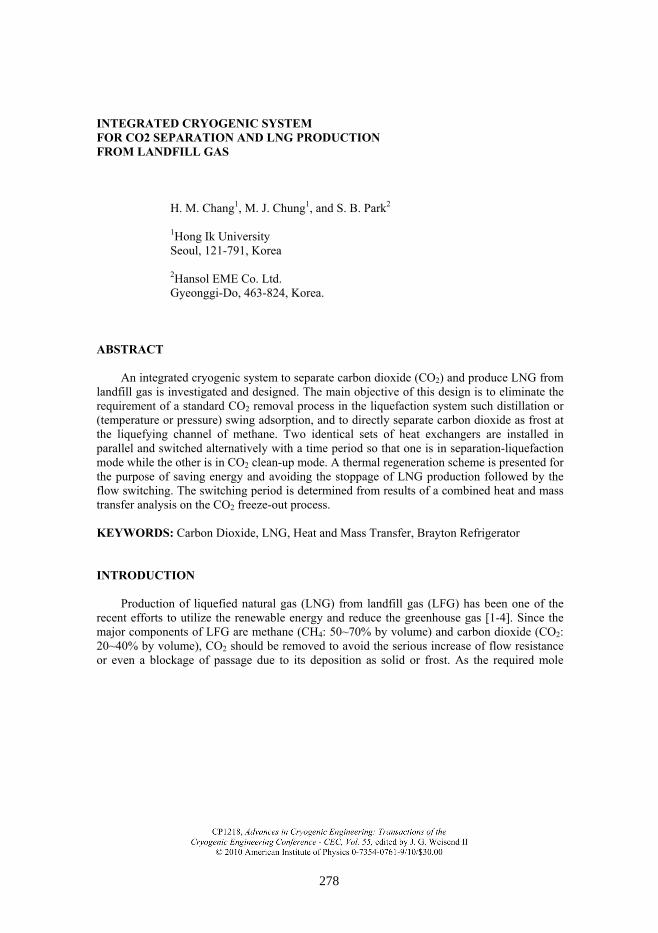
FIGURE 1 is a schematic design of the integrated system for CO2 separation and LNG
production from LFG. Closed-cycle cryogenic refrigerator with reversed-Brayton cycle is selected for the system, because the two design goals (efficiency and compactness) may be reasonably achieved [4]. Refrigerant is nitrogen gas, because it is superior to helium in energy efficiency [4]. RHX1 and RHX2 are recuperative counterflow heat exchangers of Brayton cycle, and HXA and HXB are the two identical heat exchangers that take turns alternatively in producing LNG from feed gas. In the operation mode shown in FIGURE 1, HXA plays the role of removing CO2 from the mixture and liquefying CH4 (called separation-liquefaction mode) in thermal contact with a counterflow of cold refrigerant, while the frozen CO2 in HXB is sublimated back to vapor (called clean-up mode) in thermal contact with warm refrigerant. During the sublimation process in HXB, the cold energy of CO2 frost is utilized for the cooling of high-pressure refrigerant. CO2 vapor is collected at room temperature after passing through RHX3, where the remaining cold energy of CO2 is utilized for the cooling of feed gas.
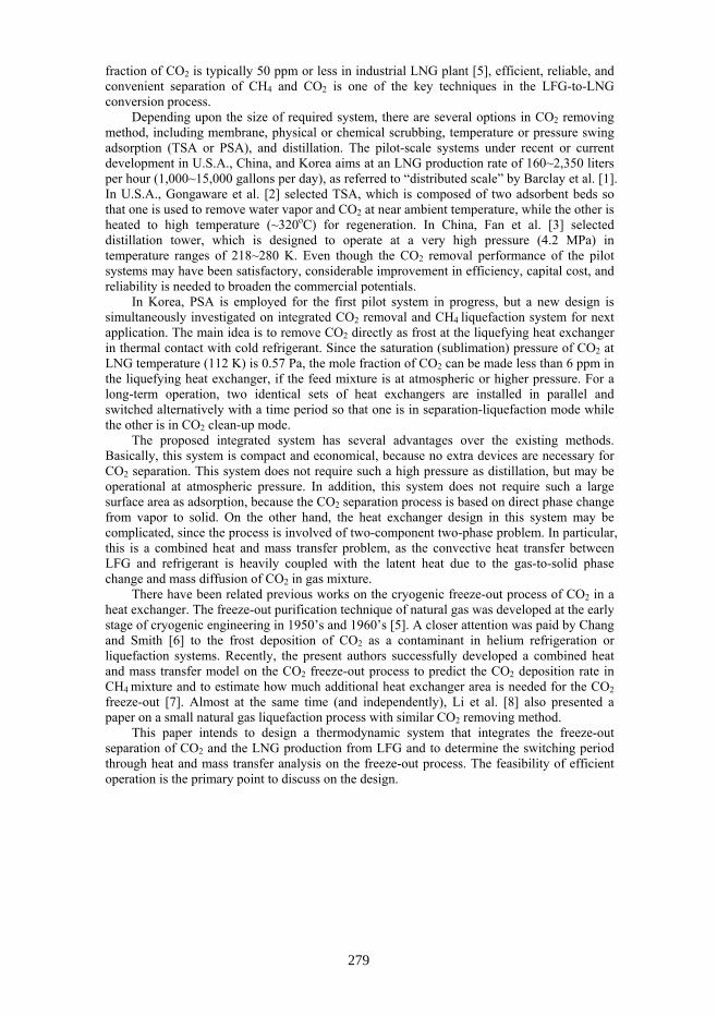
After a half cycle of operating in the mode shown in FIGURE 1, HXA and HXB swap their roles such that HXA is warmed up to release CO2 and HXB is cooled down to freeze-out CO2 and liquefy CH4. One of suggested ways to perform this swapping is to use 4-way valves to change the flow directions, as demonstrated in FIGURE 2. It is noted with the position of each valve that FIGURE 2(a) represents the first half cycle (shown in FIGURE 1) and FIGURE 2(b) represents the second half cycle.
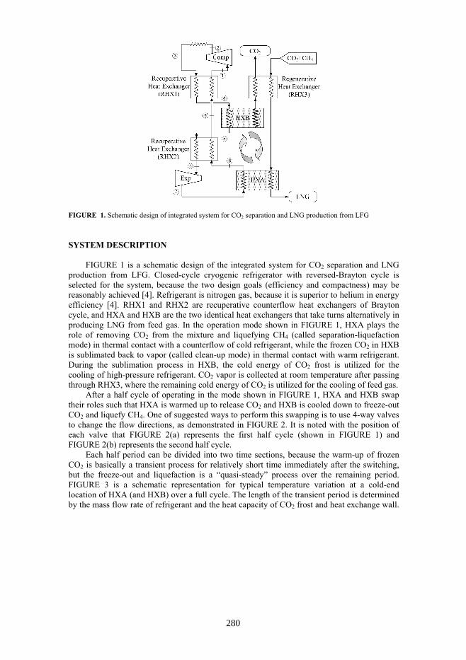
Each half period can be divided into two time sections, because the warm-up of frozen CO2 is basically a transient process for relatively short time immediately after the switching, but the freeze-out and liquefaction is a “quasi-steady” process over the remaining period. FIGURE 3 is a schematic representation for typical temperature variation at a cold-end location of HXA (and HXB) over a full cycle. The length of the transient period is determined by the mass flow rate of refrigerant and the heat capacity of CO2 frost and heat exchange wall.
FIGURE 1. Schematic design of integrated system for CO2 separation and LNG production from LFG
280
Since the amount of accumulated CO2 is nearly proportional to the freeze-out time, the most significant design parameter is the switching period, as discussed in the next section.
The warm-up temperature for cleaning HXA and HXB is another design parameter to determine. Basically, this temperature should be greater than the saturation (sublimation) temperature at atmospheric pressure (195 K). Too high temperature, however, would result in thermodynamic penalty (or entropy generation) due to the temperature fluctuation. In this design, the warm-up temperature is set around at 205 K. It should be noted in FIGURE 1 that this warm-up temperature is essentially equal to 4T during the stand-by period. In practice, 4T is determined by the relative size of RHX1 and RHX2 Since the warm end is at room temperature ( 3 298 KT ≈ ) and the cold end is close to LNG temperature ( 8 112 KT ≈ ), it is a simple and reasonable design to take the same size of heat exchanger for RHX1 and RHX2.
FIGURE 3. Schematic representation of temperature fluctuation over a full cycle in HXA and HXB
(a) (b)
FIGURE 2. Flow diagram of switching HXA and HXB for separation-liquefaction and clean-up modes
281
ESTIMATE OF CO2 ACCUMULATION RATE
The deposition rate of CO2 can be estimated with combined heat and mass transfer analysis
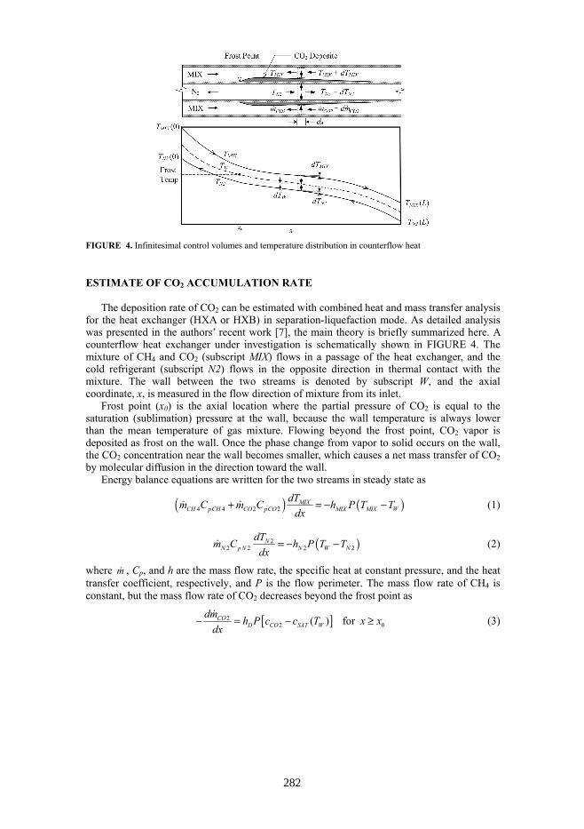
for the heat exchanger (HXA or HXB) in separation-liquefaction mode. As detailed analysis was presented in the authors’ recent work [7], the main theory is briefly summarized here. A counterflow heat exchanger under investigation is schematically shown in FIGURE 4. The mixture of CH4 and CO2 (subscript MIX) flows in a passage of the heat exchanger, and the cold refrigerant (subscript N2) flows in the opposite direction in thermal contact with the mixture. The wall between the two streams is denoted by subscript W, and the axial coordinate, x, is measured in the flow direction of mixture from its inlet.
Frost point (x0) is the axial location where the partial pressure of CO2 is equal to the saturation (sublimation) pressure at the wall, because the wall temperature is always lower than the mean temperature of gas mixture. Flowing beyond the frost point, CO2 vapor is deposited as frost on the wall. Once the phase change from vapor to solid occurs on the wall, the CO2 concentration near the wall becomes smaller, which causes a net mass transfer of CO2 by molecular diffusion in the direction toward the wall.
Energy balance equations are written for the two streams in steady state as
( ) ( )4 4 2 2MIX
CH pCH CO pCO MIX MIX WdTm C m C h P T T
dx+ = − − (1)
( )22 2 2 2
NN p N N W N
dTm C h P T Tdx
= − − (2)
where m , Cp, and h are the mass flow rate, the specific heat at constant pressure, and the heat transfer coefficient, respectively, and P is the flow perimeter. The mass flow rate of CH4 is constant, but the mass flow rate of CO2 decreases beyond the frost point as
[ ]22 0( ) for CO
D CO SAT Wdm h P c c T x x
dx− = − ≥ (3)
FIGURE 4. Infinitesimal control volumes and temperature distribution in counterflow heat
282
which is also equal to the CO2 accumulation rate per unit length. In equation (3), c is the concentration, and hD is the mass transfer coefficient of CO2 in CH4. Energy balance on the wall is that the convective cooling by refrigerant is equal to the sum of convective heat from the mixture and latent heat multiplied by CO2 accumulation rate, or
( ) ( )22 2
COMIX MIX W ig N W N
dmh P T T i h P T Tdx
⎛ ⎞− + − = −⎜ ⎟⎝ ⎠
(4)
where iig is the latent heat of sublimation. The mass flow rate and concentration of CO2 and CH4 can be related with Dalton’s model of gas mixture, and the heat and mass transfer coefficients in equations (1) trough (4) can be estimated with a reasonable accuracy from the analogy of heat and mass transfer for fully developed flow [9]
( )2 3 2 3
2 4
Pr Sc2
MIX D
CO CH pMIX MIX MIX
h h fc c C u u
= =+
(5)
where Pr and Sc are the Prandtl and Schmidt numbers of the mixture, respectively, and the friction factor f may be found from the viscous flow correlations in terms of Reynolds number. The thermal properties of fluid are evaluated with the Standard Reference Database REFPROP [10], and the mass diffusivity is estimated with Kopp’s Law of additive volumes [9]. At the inlet of MIX, TMIX(0) is fixed at 300 K and the mole fraction of CO2 (yCO2) is a variable in range of 0~30%. At the inlet of N2, TN2(L) is also fixed at 100 K for an efficient and compact design, as given by Chang et al.[4]. Pressure is assumed to be atmospheric for both streams. At the exit of mixture, TMIX(L) is also fixed at 112 K and the required heat exchanger length is found with repeated calculations.
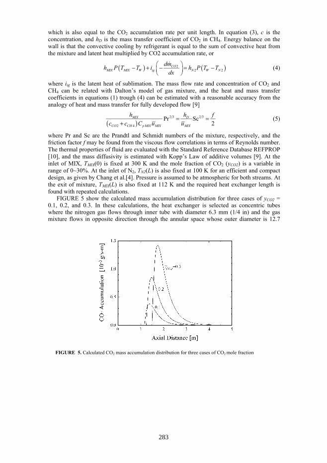
FIGURE 5 show the calculated mass accumulation distribution for three cases of yCO2 = 0.1, 0.2, and 0.3. In these calculations, the heat exchanger is selected as concentric tubes where the nitrogen gas flows through inner tube with diameter 6.3 mm (1/4 in) and the gas mixture flows in opposite direction through the annular space whose outer diameter is 12.7
FIGURE 5. Calculated CO2 mass accumulation distribution for three cases of CO2 mole fraction
283
mm (1/2 in). The mass flow rate of CH4 (not the mixture) in a tube is 0.185 g/s (for 100 parallel tubes to produce 1,000 gallons LNG/day), and the mass flow rate of N2 is fixed at 0.740 g/s. As yCO2 increases, the required heat exchanger length increases and the frost point moves farther downstream, but the curves have nearly a similar shape that has a sharp peak near the frost point and then gradually decays along the flow. This means that most of CO2 frost will be deposited at immediate downstream of the frost point. The peak accumulation rate is a significant value with which the switching period should be determined as demonstrated in next section. SWITCHING PERIOD
As CO2 frost is accumulated on the heat exchanger wall, the thermal resistance between the two fluids gradually increases, and the flow passage of gas mixture also gradually shrinks. In order to avoid a serious reduction in LNG production rate, the switching period should be short in comparison with the frost growing speed. On the other hand, too frequent switching would result in thermodynamic inefficiency due to the transient cool-down and warm-up.
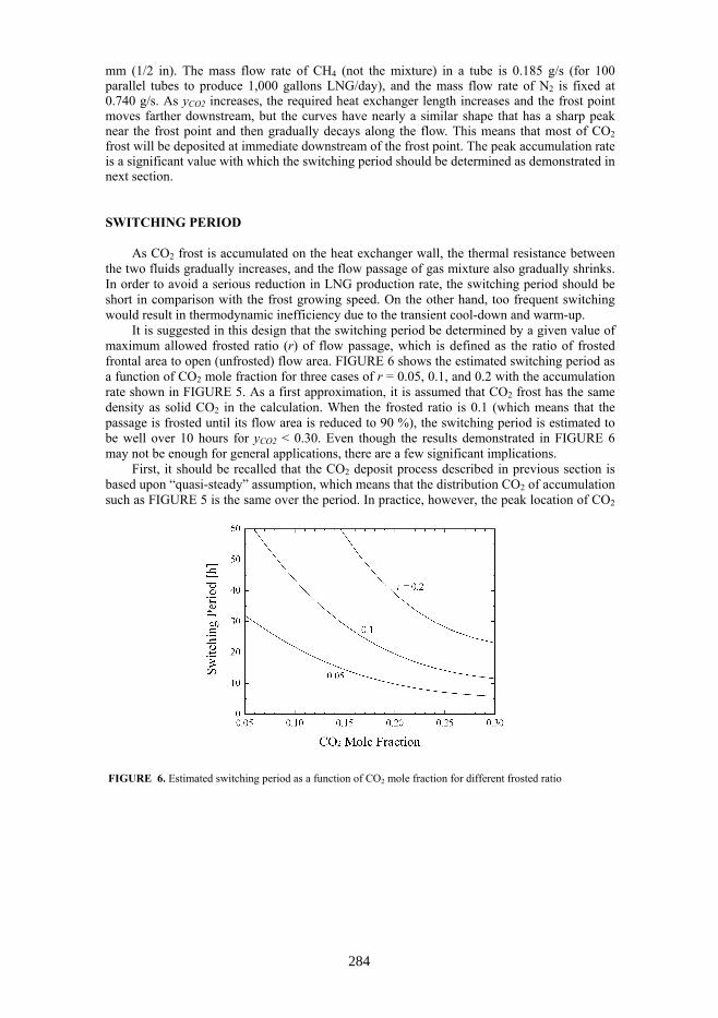
It is suggested in this design that the switching period be determined by a given value of maximum allowed frosted ratio (r) of flow passage, which is defined as the ratio of frosted frontal area to open (unfrosted) flow area. FIGURE 6 shows the estimated switching period as a function of CO2 mole fraction for three cases of r = 0.05, 0.1, and 0.2 with the accumulation rate shown in FIGURE 5. As a first approximation, it is assumed that CO2 frost has the same density as solid CO2 in the calculation. When the frosted ratio is 0.1 (which means that the passage is frosted until its flow area is reduced to 90 %), the switching period is estimated to be well over 10 hours for yCO2 < 0.30. Even though the results demonstrated in FIGURE 6 may not be enough for general applications, there are a few significant implications.
First, it should be recalled that the CO2 deposit process described in previous section is based upon “quasi-steady” assumption, which means that the distribution CO2 of accumulation such as FIGURE 5 is the same over the period. In practice, however, the peak location of CO2
FIGURE 6. Estimated switching period as a function of CO2 mole fraction for different frosted ratio
284
accumulation will shift gradually towards its downstream, as the frost layer grows and the thermal resistance increases. This implies that the actual switching period may be longer than FIGURE 6 indicates, because the actual CO2 accumulated area should be more widely spread-out. Another important design parameter in associated with CO2 deposition is the mass flow ratio of two fluids in the heat exchanger (e.g. HXA in FIGURE 1). Generally speaking, as the flow rate of N2 gas (refrigerant) increases, the axial temperature gradient of CH4-CO2 mixture becomes steeper, thus the peak CO2 accumulation rate increases. The effect of mass flow rate on the peak value, however, is not so great, as discussed in [7]. In summary, the selection of switching period as 12 hours (i.e. 24 hours for a full cycle) is reasonable for the suggested system. CONCLUSIONS
An integrated system of CO2 separation and LNG production is proposed and designed. In combination with reversed-Brayton cycle, a process flow diagram is presented for the integrated system such that two identical heat exchangers may alternatively take turns in separation-liquefaction and clean-up. Specific schemes to reduce thermodynamic penalty caused by the periodical warm-up are included in the proposed design. The distribution of CO2 accumulation rate in the heat exchanger is estimated with combined heat and mass transfer analysis, and the results are used to determine the switching period. The proposed design may be evaluated as feasible, and an experimental verification is underway. ACKNOWLEDGMENTS
This study has been supported by the research fund of the Korea New and Renewable Energy Center (KNREC) under the Ministry of Knowledge Economy in Korea. REFERENCES 1. Barclay, M.A., Gongaware, E.F., Dalton, K. and Skrzypkowski, M.P., Advances in Cryogenic Engineering
49, pp. 75-82 (2004). 2. Gongaware, D.F., Barclay, M.A., Barclay, J.A. and Skrzypkowski, M.P., Advances in Cryogenic
Engineering 49, pp. 83-90 (2004). 3. Fan, Q.H., Li, H.Y., Yin, Q.S. and Jia, L.X., Advances in Cryogenic Engineering 53, pp. 1166-1174 (2008). 4. Chang, H.M., Chung, M.J., Kim, M.J. and Park, S.B., Cryogenics 49, pp. 226-234 (2009). 5. Flynn, T.M., Cryogenic Engineering, CRC Press, New York, 2008, pp. 736-742. 6. Chang, H.M. and Smith, J.L., International Journal of Heat and Mass Transfer 33, pp.1299-1306 (1990). 7. Chang, H.M., Chung, M.J. and Park, S.B., “Cryogenic Heat-Exchanger Design for Freeze-out Removal of
Carbon Dioxide from Landfill Gas,” in Proceedings of 7th JSME-KSME Thermal and Fluids Engineering Conference, edited by Kudo, K., Japan Society of Mechanical Engineers, Japan, 2008, p. A315.
8. Li, H.Y., Yin, Q.S., Fan, Q.H., Cui, J.S., Ji, Z.M., Liu, C.S., Han, G. and Jia, L.X., “Cryogenic removing of carbon dioxide in small natural gas liquefaction system,” in Proceedings of ICEC 22-ICMC 2008, edited by Chnag, H.M., Korea Institute of Applied Superconductivity and Cryogenics, Korea, 2009, pp. 207-212.
9. Rohsenow, W.M. and Choi, H.Y., Heat, Mass, and Momentum Transfer, Prentice-Hall, New Jersey, 1961, p. 382, pp. 413-419.
10. Lemmon, E.W. and Huber, M.L., NIST Reference Fluid Thermodynamic and Transport Properties Database (REFPROP). Version 8.0, U.S. National Institute of Standards and Technology, 2007.
285