integrated computer control system the national ignition ... · nif-0046265 2-jpw/jj the national...
TRANSCRIPT

John P. Woodruff NIF Project Software Architect
Lawrence Livermore National Lab
Presented at Stanford Linear Accelerator Center13 April 2000
The National Ignition FacilityIntegrated Computer Control System

NIF-00462652-jpw/jj
The National Ignition Facility is a high-energy laser for inertial confinement fusion research
Optics assemblybuilding
Amplifierpower conditioning
modules
Cavity mirrormount assembly
Periscopepolarizer mount
assembly
Target chamber
Beam control & laser diagnostic
systems Pre-amplifiermodules
Diagnosticsbuilding
Final opticssystem
Transport turningmirrors
Pockels cell assembly
Power conditioningtransmission
lines
Amplifier
Spatial filters
Switchyard support structure
Control room
Master oscillator room
NIF Project TeamLawrence Livermore National LabLos Alamos National LabSandia National LabUniv.. of Rochester/Lab for Laser Energetics

NIF-00462653-jpw/jj
Agenda for Presentation
� Requirements for NIF Computer Controls– Subsystems and operational scenarios– Typical user interface
� Integrated Timing System requirements and performance
� ICCS Software Architecture– Distributed computational resources– Frameworks– Reusable abstractions– Construction of executable processes from generic templates
� CORBA communication infrastructure– Role of interoperable distributed objects– Performance measurements

NIF-00462654-jpw/jj
Computer control system functional requirements
� Centralized control and monitoring of laser equipment� Maintain machine configuration and operational history
� Coordinate shot countdown and data archiving� Conduct shot in ‘real-time’ over 2 second period� Conduct automated shot every 8 hours with 7 by 24 operation

NIF-00462655-jpw/jj
ICCS is a distributed system that does not have hard real time requirements
� Supervisory software is event driven– Operator-initiated actions and scripted sequences do not require specific
response times– Speed requirements derive from operator needs for interactive response– Status information is propagated from the laser to updates on graphic user
screens
� No process-related hard deadlines must be met– Several hours of preparation precede shot– Shot executes in microseconds, controlled by dedicated hardware– Data gathering and reporting occurs in minutes after the shot
� Some process controls are encapsulated in front-ends– Automatic alignment– Capacitor charging

NIF-00462656-jpw/jj
The functional system description of the control system maps to distributed architecture
Front-end Processors and Controllers
(Distributed Hardware)
Supervisor System
(Distributed Software)
Distribution Infrastructure
NIF Cable Plant and Control Points Incr
easi
ng In
tegr
atio
n
NIF-00462657-jpw/jj
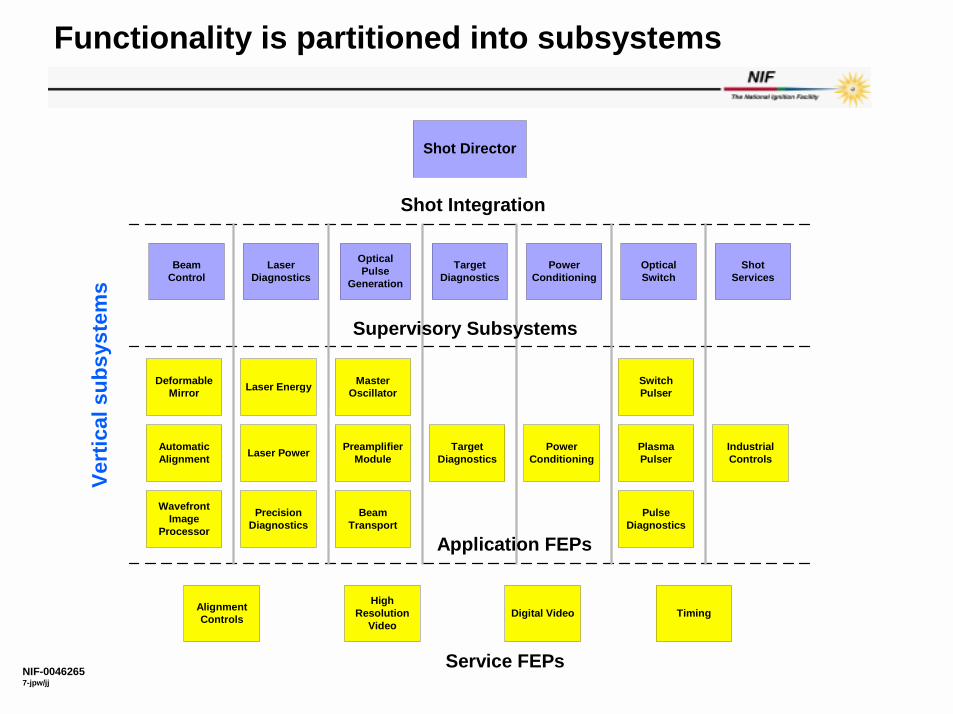
Functionality is partitioned into subsystems
Shot Director
BeamControl
OpticalSwitch
PowerConditioning
TargetDiagnostics
OpticalPulse
Generation
LaserDiagnostics
Shot Integration
DeformableMirror
PlasmaPulser
PowerConditioningLaser Power
MasterOscillatorLaser Energy
AutomaticAlignment
PreamplifierModule
TargetDiagnostics
IndustrialControls
AlignmentControls TimingDigital Video
Service FEPs
ShotServices
PrecisionDiagnostics
Supervisory Subsystems
Application FEPs
SwitchPulser
PulseDiagnostics
HighResolution
Video
WavefrontImage
Processor
BeamTransport
Vert
ical
sub
syst
ems

NIF-00462658-jpw/jj
The hardware boundary is the solid groundon which we build our software architecture
� The control points are relatively inflexible– NIF equipment will evolve only slowly– Changes to equipment will be expensive
– Therefore the software can expect to evolve slowly along with equipment evolution
� By contrast, the user interfaces and experimental execution plans will evolve more rapidly– The user community will learn innovative ways to use the facility– Experimental campaigns will arise in response to researchers’
creativity

NIF-00462659-jpw/jj
A typical user interface shows broad-view status and offers pop-up control panels

NIF-004626510-jpw/jj
Activities that constitute a shot cycle are defined as abstract state transitions
3–7 hours 30 minutes
Concurrent System
Maintenance Activities
VI Archive
Target Shot
Secondary Shot
I Begin Shot Cycle
II Populate
Plan
III Implement
PlanReady
IV Interlock
& Verify
V Countdown
Post Countdown
Shot!
~10 minutes (variable)
Cleanup Activities
End Shot Cycle
Analyze Shot & Update System
Primary Shot
Retry

NIF-004626511-jpw/jj
NIF shot in ‘real-time’ lasts 2 seconds under control of dedicated hardware
1 µs1 ms1 s 1 s1 µs 1 ms
PRE-SHOT POST-SHOT
Lamp drivers
Transient Digitizers
Framing Cameras
Trigger Examples
The Shot
T-1 Abort System - suspend wavefront control
PEPC
Arm video
PEPCSim
mer Stop
PEPCsw
itch
digitizers
Simm
er Start
Fast Timing ±10 ms (1 ns)
Computer Network
Extended Range Fast Timing ±5 s (100 ns)
Precision Timing ±1 µs (30 ps)
Computer Network
Computer Network
TargetT0

NIF-004626512-jpw/jj
Optical Pulse
Generation
Amplifier Lamps
Optical Switch
Target Diagnostics
Integrated Timing System
Power Conditioning
Laser Diagnostics
Energy Power Imaging
Optical Path
Triggers (to 30 psec resolution)
Beginning of time
The timing system orchestrates laser firing and triggering of diagnostics

NIF-004626513-jpw/jj
Trigger System Requirements
ExtendedRange
Fast units Precisionunits
# of channels 150 1900 50
Minimumrange
+/- 1 sec. +/- 55 msec. +/- 10 usec.
Resolution(setting)
<100 ns < 1 ns 20 ps
Stability(jitter)
<1 ms (jitter &wander)
<100 ps RMS(over 10 sec)
<20 ps RMS(over 10 sec)
Stability(wander)
See above < 500 ps - pk to pk(over 7 days)
<100 ps 95 %(over 7 days)

NIF-004626514-jpw/jj
ITS Trigger system is divided into two functional sub-systems
Facility Timing Sub-system
Located in one area of NIF
Local Timing Sub-systems located in 14 areas of NIF
Trigger system architecture
NIF Control Network
Master Timing Transmitter
Master Timing Measurement sub-system
Fan outRcvrs
Facility Timing FEP
14 ea..
14 ea..14 Zones
8 ch Delay Generators
Up to 32 per Zone
Local Timing FEP
1x8 FO
Splitters
Up to 4 per Zone
16 outputs.1 unassigned
Ref.
Single mode Fiber Optics components connects Facility and Local Timing hardware
Trigger System parameters set via users using computers, GUI and NIF Controls Network
NIF-004626515-jpw/jj
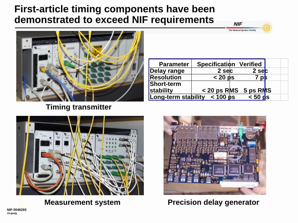
First-article timing components have been demonstrated to exceed NIF requirements
Precision delay generator
Timing transmitter
Measurement system
Parameter Specification VerifiedDelay range 2 sec 2 secResolution < 20 ps 7 psShort-term stability < 20 ps RMS 5 ps RMSLong-term stability < 100 ps < 50 ps
NIF-004626516-jpw/jj
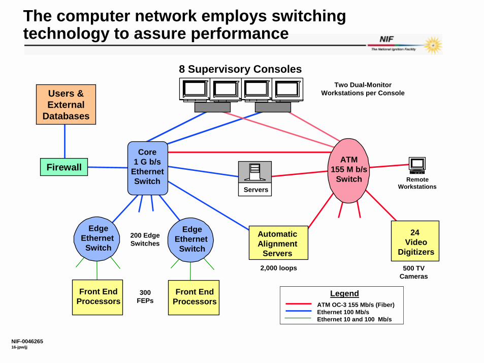
ServersRemote
Workstations
24 Video
Digitizers
ATM155 M b/s
Switch
8 Supervisory Consoles
Core1 G b/s
EthernetSwitch
EdgeEthernet Switch
The computer network employs switching technology to assure performance
AutomaticAlignment
Servers
ATM OC-3 155 Mb/s (Fiber)Ethernet 100 Mb/sEthernet 10 and 100 Mb/s
Legend
EdgeEthernet Switch
Front EndProcessors
Front EndProcessors
200 EdgeSwitches
300FEPs
500 TVCameras
2,000 loops
Two Dual-MonitorWorkstations per Console
Firewall
Users & External
Databases

NIF-004626517-jpw/jj
Software applications are built upon a framework of distributed services
Integration Services Supervisory Console
Front End Processor
StatusMonitor
DeviceControl
- System manager - Device hierarchy - Access control
StatusDisplay
OperatorControls
Database - History - Shots - Configuration
EventLog
Interface Driver
Software Distribution Bus (exists on network)
Controller
Object Request Broker
Software objects representing control points “plug in” to the software distribution bus
300 front-end processors
interface to NIF equipment
CORBA
Server Workstation
NIF-004626518-jpw/jj
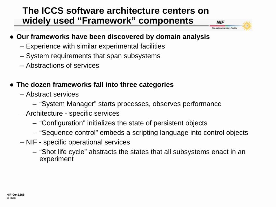
The ICCS software architecture centers on widely used “Framework” components
� Our frameworks have been discovered by domain analysis– Experience with similar experimental facilities– System requirements that span subsystems– Abstractions of services
� The dozen frameworks fall into three categories– Abstract services
– “System Manager” starts processes, observes performance– Architecture - specific services
– “Configuration” initializes the state of persistent objects– “Sequence control” embeds a scripting language into control objects
– NIF - specific operational services– “Shot life cycle” abstracts the states that all subsystems enact in an
experiment

NIF-004626519-jpw/jj
These abstract frameworks are being built with prospective reuse in mind� Managing the lives of processes and application objects
– System manager– Generic main programs– Configuration: delivers database services
� Organizing operational records– Message Log– Machine history– Shot Data archive
� Distributing up-to-date device status– Status monitor: polls locally and pushes updates
� Managing interactions with operators– Graphic user interface– Reservation– Sequence control language– Alert notification
� Implementing the state transitions in an experiment

NIF-004626520-jpw/jj
All supervisor and FEP programs are built by elaborating a generic template
Configuration Server
Central System
Manager
Private Application
Objects
Local System Manager
Public Application
Objects
Main
Private Factory
Public Factory
DBMS
Generic Application
Controller Objects
Local System
Manager
Device Objects
Main
Controller Factory
Device Factory
Generic FEP

NIF-004626521-jpw/jj
Abstract frameworks are (largely)independent of each other
� Four frameworks provide distinct information services– Configuration: data to start devices
– Example: signal level addresses, instrument calibration– Message log: audit trail of operator action and system responses– Machine history: service records of device performance– Shot archive: results of physics experiments
� The different information services share common features– Devices are named consistently in each data record– Records can be correlated, for example by time stamp
� But the Policies that connect them are not inherent in the frameworks themselves
� Additional templates (for innovative frameworks) can be introduced without disturbing components already in place.

NIF-004626522-jpw/jj
Frameworks are constructed in layers to permit retargeting
Framework Templates Layer
Abstract classes for control systems
Abstract devices, Configuration, Monitor, etc
Devices, Shot phases, etc
NIF Building blocks
Classes that model equipment
Support layer
COTS and components
Oracle DBMS, ORBexpress, etc
Framework Services
Customized for a specific system
Configuration Server, System Manager, GUI’s, etc
ICCS Programs
Client and server mainlines
Supervisor applications, Front End Processors, Database servers, etc

NIF-004626523-jpw/jj
The framework services layer is specific to NIF, built by extending reusable framework abstractions
� The Framework Services are delivered when dispatching operationsdefined in the template are applied to concrete classes.– The “Device” class is an abstract superclass
– This base class defines interfaces applicable to all devices– for naming – for reserving on behalf of an operator – for multi-task safety
– Several dozen derived classes control physical equipment– Diverse actions defined for motors, power supplies, diagnostic
instruments, precision timing and triggering– Initialization from a central database
– Descendents of the abstract device class provide actual operations to control physical NIF parts

NIF-004626524-jpw/jj
Dependencies between levels are strictly hierarchic
� Subsystems within a particular layer can only depend upon subsystems at the same or a lower layer– This allows classes at a given layer to be replaced or extended– Only layers above the replacement are affected
� Replacement of the all the concrete classes derived from Device could make the “Application services” frameworks available for a different kind of experimental facility– Adding new subclasses of Device enables evolution of the NIF– Replacement of state transition actions would produce new operational
services

NIF-004626525-jpw/jj
Numerous GUI’s receive status updates from Supervisors
� Separate the operator interaction from system behavior
� Provide a consistent multi-display view of the system state
� Economize on message traffic by “pushing” status changes
Logical Control Unit Front End
Processor
Commands
Graphical User
Interface 1
Graphical User
Interface 2
Updates
Commands
Commands
Updates
Updates
NIF-004626526-jpw/jj
Efforts to economize on message traffic
� Status of every Device must be observable at multiple consoles – Some status reports require latency as small as 0.1 second– Monitor objects are co-located with Devices
– Local polling in the FEP– Notification of “significant” change
� Supervisory objects collect and collate change reports– GUI’s that display “broad view” status subscribe to these supervisors– GUI’s receive their status updates via “data push” from the supervisor
NIF-004626527-jpw/jj
CORBA provides decentralized distribution services
� A standard model of distributed objects resolves a major development risk– ICCS software engineers are freed from building a
“homebrew”communication infrastructure– Anticipate 30-year life of the standard
� CORBA defines loose coupling between objects– Communication becomes nearly invisible
– Neither clients nor servers depend directly on communication infrastructure
– Names of communicating objects hide locations– Transparent interoperability
– IDL specifications are language-neutral interfaces– Data marshalling hides differences between hosts
� Allocation of object implementations to processes can be deferred

NIF-004626528-jpw/jj
ICCS uses CORBA to distribute Ada-95 objects
� Each of the 60,000 control points is controlled by one of the Front-End processors– Each is implemented as an instance of a class derived from Device– These derived classes are specified using Interface Definition Language
(IDL)
� The ORBexpress IDL compiler translates the IDL to an Ada interface package and an implementation package
� “Abstract” classes that are defined by IDL translate to a concrete interface defining a classwide reference
� Framework objects perform their operations by dispatching calls on these classwide references
� ORBexpress produces invocations of the methods in the corresponding implementation

NIF-004626529-jpw/jj
The majority of NIF’s CORBA objects are long-lived
� 60_000 objects implement the class Device in Front-End Processors– About 130 subclasses – Each instance is initialized at system start-up– A framework manages data and naming
– Oracle database maintains configuration– Persistence broker objects implement SQL queries on behalf of
CORBA clients
� A dead server is an error to be diagnosed and recovered– Failover to a replacement of the same class is not automated

NIF-004626530-jpw/jj
Using IDL to define interfaces implies some compromises
� Interfaces must be declared in terms of IDL types– These types “diffuse” into the rest of the system– IDL type model is less strict than Ada’s
– No range constraints– No initial values for record components
– No default parameter values– No operator overloading in interfaces
� Configuration management must accommodate to the possibility that implementation details might be loaded into client processes

NIF-004626531-jpw/jj
Measurements of ORBexpress 2.0.1confirm adequate performance� Network is 100 Megabit ethernet� Both client and server are 2-processor Sun Enterprise 3000’s
– Client runs 40 Ada tasks; server runs 5 – Runtime is Apex 3.0
– GNAT 3.11 is roughly 10% faster
0
300
600
900
1200
1500
1800
2100
2400
2700
3000
Message Size (Bytes)
0%
10%
20%
30%
40%
50%
60%
70%
80%
90%
100%
Msg Rate (100Mbit)% Client CPU% Server CPU% Network

NIF-004626532-jpw/jj
The ICCS strategy rests on two main decisions
� Single unified architecture unites all subsystems– Frameworks implement abstractions for widespread use– Distributed object-oriented system exploits CORBA– Design patterns embody programming choices
– Publisher-subscriber relationships– Model-view-controller idiom for user interface
� Managed process guides development– Ada is the principle programming language– Documents are written and reviewed– Development proceeds incrementally– Code walkthroughs catch errors early in cycle– Each cycle of development is reviewed
– Process is adjusted to incorporate lessons learned

NIF-004626533-jpw/jj
A disciplined engineering process manages incremental construction and release of code
UnixTarget
Object-Oriented Design Tool
Requirement Specification
Design Description
NIF Software
Ada HostCompiler
Ada Cross Compiler
Ada Language Editor
Interface Specification
Object Model
Real-time Target
Reverse Engineering
AutomaticCode Generationof SpecificationsEngineers w rite
code details
Object Request Broker Distribution
TargetArchitectures
Sun Sparc VxWorks PowerPC
Engineers modelsoftw are framew ork
Architecture Neutral
CORBA

NIF-004626534-jpw/jj
DISCLAIMERUCRL-VG-138473
� This document was prepared as an account of work sponsored by anagency of the United States Government. Neither the United States Government nor the University of California nor any of their employees, makes any warranty, express or implied, or assumes any legal liability or responsibility for the accuracy, completeness, or usefulness of any information, apparatus, product, or process disclosed, or represents that its use would not infringe privately owned rights. Reference herein to any specific commercial product, process, or service by trade name, trademark, manufacturer, or otherwise, does not necessarily constitute or imply its endorsement, recommendation, or favoring by the United States Government or the University of California. The views and opinions of authors expressed herein do not necessarily state or reflect those of the United States Government or the University of California, and shall not be used for advertising or product endorsement purposes.
� This work was performed under the auspices of the U.S. Department of Energy by University of California Lawrence Livermore National Laboratory under contract No. W-7405-Eng-48.