intech-solid waste management through the application of thermal methods
TRANSCRIPT
8/13/2019 InTech-Solid Waste Management Through the Application of Thermal Methods
http://slidepdf.com/reader/full/intech-solid-waste-management-through-the-application-of-thermal-methods 1/37
6
Solid Waste Managementthrough the Application of Thermal Methods
Konstantinos Moustakas and Maria Loizidou National Technical University of Athens,
School of Chemical Engineering,
Unit of Environmental Science & Technology
9, Heroon Polytechniou Street, Zographou Campus, Athens
Greece
1. Introduction
Human life in modern societies is inevitably related to waste generation. Around 255million tones of municipal solid waste were generated in the 27 Member-States of theEuropean Union in 2006, an increase of 13% in comparison to 1995. This represented anaverage of 517 kg of municipal waste per capita, an increase of 9% over 1995. Therefore, it isnot strange that waste management has become a crucial subject with increasing interest forscientists, local authorities, companies and simple citizens.The effective management of solid waste involves the application of various treatment
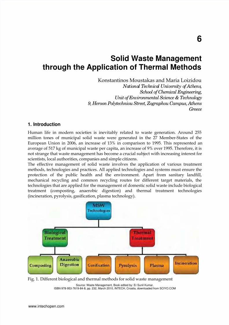
methods, technologies and practices. All applied technologies and systems must ensure theprotection of the public health and the environment. Apart from sanitary landfill,mechanical recycling and common recycling routes for different target materials, thetechnologies that are applied for the management of domestic solid waste include biologicaltreatment (composting, anaerobic digestion) and thermal treatment technologies(incineration, pyrolysis, gasification, plasma technology).
Fig. 1. Different biological and thermal methods for solid waste management
Source: Waste Management, Book edited by: Er Sunil Kumar,ISBN 978-953-7619-84-8, pp. 232, March 2010, INTECH, Croatia, downloaded from SCIYO.COM
www.intechopen.com

8/13/2019 InTech-Solid Waste Management Through the Application of Thermal Methods
http://slidepdf.com/reader/full/intech-solid-waste-management-through-the-application-of-thermal-methods 2/37
Waste Management90
This chapter focuses on the description of the alternative thermal practices for municipalsolid waste management. Thermal methods for waste management aim at the reduction ofthe waste volume, the conversion of waste into harmless materials and the utilization of theenergy that is hidden within waste as heat, steam, electrical energy or combustible material.
They include all processes converting the waste content into gas, liquid and solid productswith simultaneous or consequent release of thermal energy.According to the New Waste Framework Directive 2008/98/EC, the waste treatmentmethods are categorized as “Disposal” or “Recovery” and the thermal managementpractices that are accompanied by significant energy recovery are included in the“Recovery” category. In addition, the pyramid of the priorities in the waste managementsector shows that energy recovery is more desired option in relation to the final disposal.
Fig. 2. Pyramid of the priorities in the waste management sector
That is why more and more countries around the world develop and apply Waste-to-Energytechnologies in order to handle the constantly increasing generated municipal waste.Technologically advanced countries in the domain of waste management are characterizedby increased recycling rates and, at the same time, operation of a high number of Waste-to-Energy facilities (around 420 in the 27 European Member-States). More specifically, on thebasis of Eurostat data the percentages of municipal waste treated with thermal methods forthe year 2007 in Denmark, Sweden, Luxembourg, Netherlands, France (Autret et al., 2007),Germany, Belgium and Austria were 53%, 47%, 47%, 38%, 36%, 35%, 34% and 28%respectively. On the other hand, there are still Member-States that do not apply thermaltechniques in order to handle the generated municipal waste, especially in the southernEurope and the Baltic Sea. Such countries include Bulgaria, Estonia, Iceland, Cyprus, Latvia,Lithuania, Slovenia, Malta, Poland, Romania and Greece.General information about the use of thermal technologies for solid waste managementaround Europe and worldwide is provided. Data referring to incineration – mass burncombustion, pyrolysis, gasification and plasma technology is presented. The differentaspects of each technology, the indicative respective reactions, as well as the products ofeach thermal process, are described. The issue of air emissions and solid residues isaddressed, while the requirements for cleaning systems are also discussed for each case.
Dis osal
Munici al Solid Waste
Prevention
Reuse
Rec clin
RecoveryEnergy Recovery
www.intechopen.com
8/13/2019 InTech-Solid Waste Management Through the Application of Thermal Methods
http://slidepdf.com/reader/full/intech-solid-waste-management-through-the-application-of-thermal-methods 3/37
Solid Waste Management through the Application of Thermal Methods 91
Finally, the first attempt to treat municipal waste in Greece with the use of gasification /vitrification process is presented.
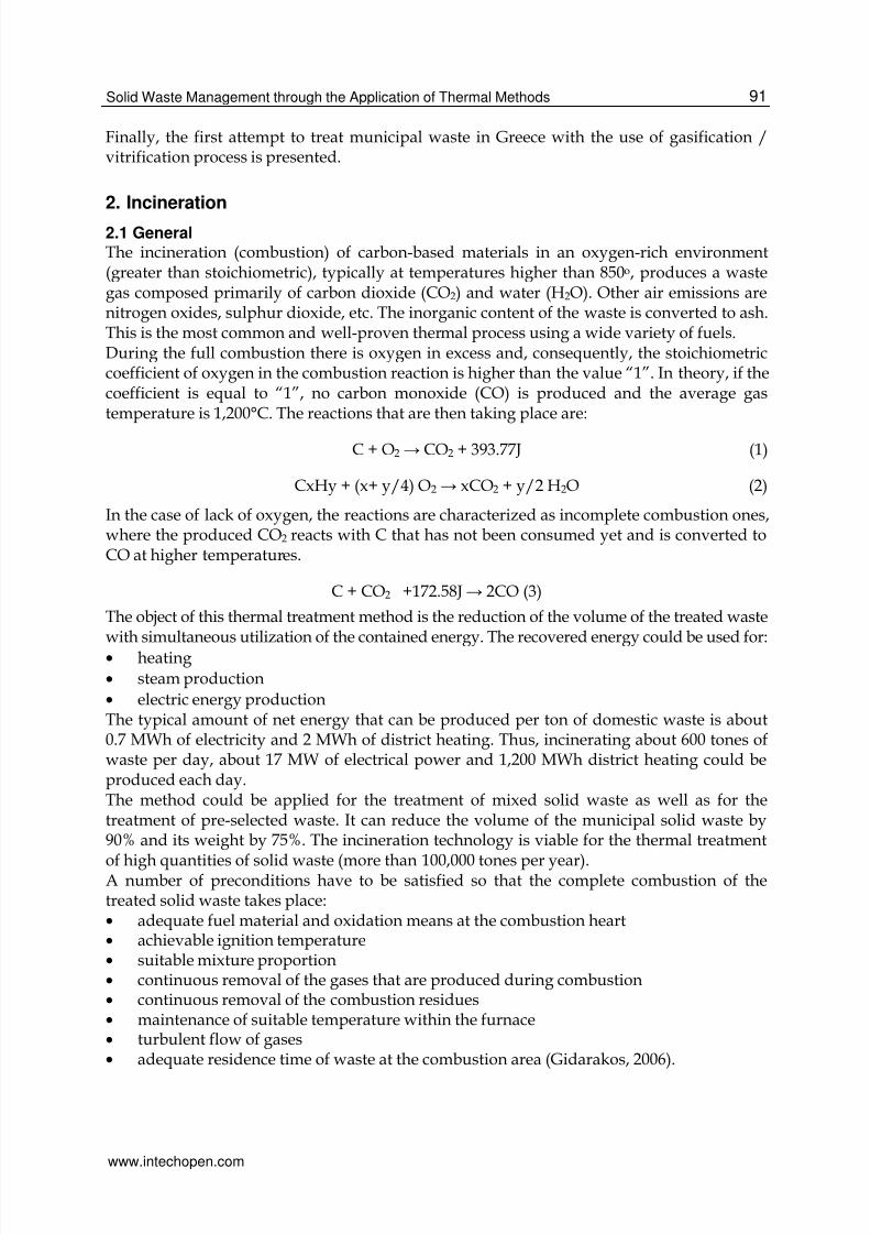
2. Incineration
2.1 GeneralThe incineration (combustion) of carbon-based materials in an oxygen-rich environment(greater than stoichiometric), typically at temperatures higher than 850o, produces a wastegas composed primarily of carbon dioxide (CO2) and water (H2O). Other air emissions arenitrogen oxides, sulphur dioxide, etc. The inorganic content of the waste is converted to ash.This is the most common and well-proven thermal process using a wide variety of fuels.During the full combustion there is oxygen in excess and, consequently, the stoichiometriccoefficient of oxygen in the combustion reaction is higher than the value “1”. In theory, if thecoefficient is equal to “1”, no carbon monoxide (CO) is produced and the average gastemperature is 1,200°C. The reactions that are then taking place are:
C + O2 → CO2 + 393.77J (1)
CxHy + (x+ y/4) O2 → xCO2 + y/2 H2O (2)
In the case of lack of oxygen, the reactions are characterized as incomplete combustion ones,where the produced CO2 reacts with C that has not been consumed yet and is converted toCO at higher temperatures.
C + CO2 +172.58J→ 2CO (3)
The object of this thermal treatment method is the reduction of the volume of the treated wastewith simultaneous utilization of the contained energy. The recovered energy could be used for:
• heating
• steam production
• electric energy productionThe typical amount of net energy that can be produced per ton of domestic waste is about0.7 MWh of electricity and 2 MWh of district heating. Thus, incinerating about 600 tones ofwaste per day, about 17 MW of electrical power and 1,200 MWh district heating could beproduced each day.The method could be applied for the treatment of mixed solid waste as well as for thetreatment of pre-selected waste. It can reduce the volume of the municipal solid waste by90% and its weight by 75%. The incineration technology is viable for the thermal treatment
of high quantities of solid waste (more than 100,000 tones per year).A number of preconditions have to be satisfied so that the complete combustion of thetreated solid waste takes place:• adequate fuel material and oxidation means at the combustion heart• achievable ignition temperature• suitable mixture proportion• continuous removal of the gases that are produced during combustion• continuous removal of the combustion residues• maintenance of suitable temperature within the furnace• turbulent flow of gases• adequate residence time of waste at the combustion area (Gidarakos, 2006).
www.intechopen.com

8/13/2019 InTech-Solid Waste Management Through the Application of Thermal Methods
http://slidepdf.com/reader/full/intech-solid-waste-management-through-the-application-of-thermal-methods 4/37
Waste Management92
Fig. 3. A schematic diagram of incineration process
The existing European legislative framework via the Directive 2000/76/EC prevents andlimits as far as practicable negative effects on the environment, in particular pollution byemissions into air, soil, surface water and groundwater, and the resulting risks to humanhealth, from the incineration and co-incineration of waste (European Commission, 2000).
Photo 1. MSW incineration plants in Amsterdam, Brescia & Vienna respectively
www.intechopen.com

8/13/2019 InTech-Solid Waste Management Through the Application of Thermal Methods
http://slidepdf.com/reader/full/intech-solid-waste-management-through-the-application-of-thermal-methods 5/37
Solid Waste Management through the Application of Thermal Methods 93
2.2 Typical Incineration plantA typical incineration plant includes:
Weighing System
The system for weighing solid waste aims at the control and recording of the incomingloads and it has to be practical so as to minimize the time that vehicles remain at thispoint.
Reception Site
Due to the fact that waste does not arrive on continuous basis (contrary to the feeding of thefacility), the existence of waste reception and temporary storage site is considered necessary.The design of the site is made in a way that the following are ensured:
• the unloading time is as little as possible
• all transferred waste is received
• the homogeneity of the waste that will be used as feeding material is achieved
• the smooth feeding of the facility is ensuredMoreover, the design of the reception site should be based on the minimization of the
environmental consequences. For instance, the solid waste should remain for maximum two
days so as to avoid odours, while the bottom of the site has to be characterised by
weathering to allow the leachates and washing wastewater to go away.
Feeding System
The feeding system has to be adapted to the rate and feeding velocity of the installation.
Combustion Hearths
The ignition of solid waste at incineration facilities is achieved through the use of specific
burner, which operates with secondary fuel. Basic parameters for the appropriate operationof the combustion hearths are:
• achievement of the minimum desired temperature
• adequate combustion time
• achievement of turbulence conditions / homogenous waste incineration
Boiler
The boiler is the system with which the energy content of the fuel material (hot off-gases)
can be utilized in a suitable way through steam production (e.g. at neighbouring industrial
facilities or for the heating of urban areas. Pressure, temperature and steam production rate
are basic parameters for the effective operation of the boiler.
System for the removal of residues
Residues represent 20 - 40% of the weight of the initial waste and are categorized into:
• Residues that go out of the grates: 20 - 35%
• Residues that go through the grates: 1 - 2%The residues are collected at hoppers where they are transferred with specific system forcooling.
Emission control system
The role of the emission system control focuses on particles, HCl, HF, SO2, dioxins and
heavy metals and is discussed below (Niessen, 2002).
www.intechopen.com

8/13/2019 InTech-Solid Waste Management Through the Application of Thermal Methods
http://slidepdf.com/reader/full/intech-solid-waste-management-through-the-application-of-thermal-methods 6/37
Waste Management94
2.3 Typical emissions from incinerationsThe emissions derived from the operation of typical incinerations plants include:1. Air emissionsThe generated air emissions contain the typical combustion products (CO, CO2, NOx, SO2),
excess of oxygen, dust particles as well as other compounds. The presence and theconcentration of other compounds, such as ΗCl, HF, suspended particles which containheavy metals, dioxins and furans, depend on the composition of the waste that is subjectedto incineration. During incineration, a quantity of 4,000 – 5,000 m3 of air emissions isgenerated per ton of waste.Air emissions must be controlled by applying appropriate anti-pollution systems, such as:• Bagfilters
• Electrostatic filters
• Cyclones
• Wet cleaning systems, e.g. scrubbers, wet cleaning towers, rotate sprayers, etc.Dioxin or furan refers to molecules or compounds composed of carbon and oxygen. These
compounds when reacting with halogens, such as chlorine or bromine, acquire toxicproperties. Most research on halogenated dioxin and furan has been concerned withchlorinated species. It is generally accepted that dioxin and furan are by-products ofcombustion processes including domestic and medical waste combustion or incinerationprocesses. In combustion processes, hydrocarbon precursors react with chlorinatedcompounds or molecules to form furans or/and dioxins. They may also be generated in apost-combustion flue gas cooling system due to the presence of precursor compounds, freechlorine, or unburned carbon and copper species in the fly ash particles.The toxic influence of dioxins and furans had not been made clear until the end of thedecade of 80. The application of the MACT Regulations led to the drastic reduction of theTEQ-Toxic equivalent of the dioxin emissions. As a result, the dioxin emissions have been
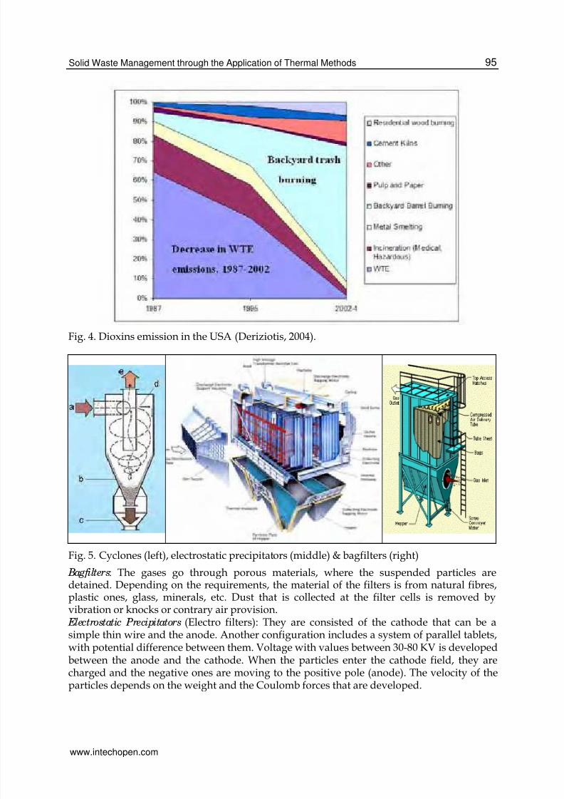
limited to one thousandth in relation to the year 1987, reaching values lower than 10 gr TEQper year (Fig. 4). It should also be noted that on the basis of data provided by the US EPAthe uncontrolled burning of waste is considered as the main source of dioxins, producingaround 600 gr annually.Dioxins and furans are produced in almost all combustion processes, in the gas phase, whilethe exact mechanism for their formation is not known. It is known that their formationtemperature is 300C°, temperatures where two reactions are possible, formation anddecomposition. The existence of chlorinated organic substances in waste and the increase oftheir content in oxygen encourage their formation. Consequently, the operating conditionsof incinerators influence the dioxin formation at higher degree than the waste compositionand PVC quantity included in it.
There are indications for the contribution of dioxins and furans to human cancers, fact thatmakes necessary to take basic and secondary measures so as to limit such emissions.In order to remove the suspended particles and the gas pollutants, different cleaningsystems can be applied. Indicatively, deposition chambers, where 40% of suspended solidsis removed, cyclones (removal efficiency 60-80%), wet cleaning towers (removal efficiency80-95%), electrostatic precipitators (removal efficiency 99-99.5%) and bagfilters (removalefficiency 99.9%) are referred. Apart from the removal of suspended solids, it is oftennecessary to remove other gas pollutants in the case that they exceed the limit values (likeHCl generated during the combustion of PVC and oxides of nitrogen, sulphur andphosphorus. Next, the main cleaning systems that are used for the treatment of the gasproducts during incineration are briefly described.
www.intechopen.com
8/13/2019 InTech-Solid Waste Management Through the Application of Thermal Methods
http://slidepdf.com/reader/full/intech-solid-waste-management-through-the-application-of-thermal-methods 7/37
Solid Waste Management through the Application of Thermal Methods 95
Fig. 4. Dioxins emission in the USA (Deriziotis, 2004).
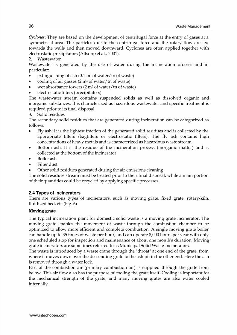
Fig. 5. Cyclones (left), electrostatic precipitators (middle) & bagfilters (right) Bagfilters: The gases go through porous materials, where the suspended particles aredetained. Depending on the requirements, the material of the filters is from natural fibres,plastic ones, glass, minerals, etc. Dust that is collected at the filter cells is removed byvibration or knocks or contrary air provision. Electrostatic Precipitators (Electro filters): They are consisted of the cathode that can be asimple thin wire and the anode. Another configuration includes a system of parallel tablets,with potential difference between them. Voltage with values between 30-80 KV is developedbetween the anode and the cathode. When the particles enter the cathode field, they arecharged and the negative ones are moving to the positive pole (anode). The velocity of theparticles depends on the weight and the Coulomb forces that are developed.
www.intechopen.com
8/13/2019 InTech-Solid Waste Management Through the Application of Thermal Methods
http://slidepdf.com/reader/full/intech-solid-waste-management-through-the-application-of-thermal-methods 8/37

8/13/2019 InTech-Solid Waste Management Through the Application of Thermal Methods
http://slidepdf.com/reader/full/intech-solid-waste-management-through-the-application-of-thermal-methods 9/37
Solid Waste Management through the Application of Thermal Methods 97
Secondary combustion air is supplied into the boiler at high speed through nozzles over thegrate. It facilitates complete combustion of the flue gases by introducing turbulence forbetter mixing and by ensuring a surplus of oxygen. In multiple/stepped hearth incinerators,the secondary combustion air is introduced in a separate chamber downstream the primary
combustion chamber.According to the European Waste Incineration Directive, incineration plants must bedesigned to ensure that the flue gases reach a temperature of at least 850 °C for 2 seconds inorder to ensure proper breakdown of organic toxins. In order to comply with this at alltimes, it is required to install backup auxiliary burners (often fueled by oil), which are firedinto the boiler in case the heating value of the waste becomes too low to reach thistemperature alone.The flue gases are then cooled in the superheaters, where the heat is transferred to steam,heating the steam to typically 400 °C at a pressure of 40 bar for the electricity generation inthe turbine. At this point, the flue gas has a temperature of around 200 °C, and is passed tothe flue gas cleaning system.
Often incineration plants consist of several separate 'boiler lines' (boilers and flue gastreatment plants), so that waste receival can continue at one boiler line, while the others aresubject to revision.
Fixed grate
The older and simpler type of incinerator was a brick-lined cell with a fixed metal grate overa lower ash pit, with one opening in the top or side for loading and another opening in theside for removing incombustible solids called clinkers.
Rotary-kiln
The rotary kiln incinerator is applied by municipalities and by large industrial plants. Thistype of incinerator has two chambers, a primary chamber and secondary chamber. The
primary chamber consists of an inclined refractory lined cylindrical tube. Movement of thecylinder on its axis facilitates movement of waste. In the primary chamber, there isconversion of solid fraction to gases, through volatilization, destructive distillation andpartial combustion reactions. The secondary chamber is necessary to complete gas phasecombustion reactions.The clinkers spill out at the end of the cylinder. A tall flue gas stack, fan, or steam jetsupplies the needed draft. Ash drops through the grate, but many particles are carried alongwith the hot gases. The particles and any combustible gases may be combusted in an"afterburner".
Fluidized bed
According to the technology that is applied for this type of incinerator, a strong airflow isforced through a sand bed. The air seeps through the sand until a point is reached where thesand particles separate to let the air through and mixing and churning occurs, thus a fluidizedbed is created and fuel and waste can now be introduced (European Commission, 2006).
3. Gasification
3.1 GeneralGasification is the thermal process that converts carbon-containing materials, such as coal,petcoke, biomass, sludge, domestic solid waste to syngas which can then be used to produceelectric power, valuable products, such as chemicals, fertilizers, substitute natural gas,
www.intechopen.com

8/13/2019 InTech-Solid Waste Management Through the Application of Thermal Methods
http://slidepdf.com/reader/full/intech-solid-waste-management-through-the-application-of-thermal-methods 10/37
Waste Management98
Fig. 6. three types of incinerators: (a) fixed grate, (b) rotary kiln, (c) fluidized bed
hydrogen, steam and transportation fuels. Gasification is defined as a thermal reaction withinsufficient oxygen present for reaction of all hydrocarbons (compounds of carbon,hydrogen and oxygen molecules) to CO2 and H2O. This is a partial oxidation process whichproduces a composite gas (syngas) comprised primarily of hydrogen (H2) and carbonmonoxide (CO).The major benefit of gasification of biowaste is that the product gas can be used directly,after significant cleaning, to fuel a gas turbine generator which itself will form part of aCombined Heat and Power (CHP) or Combined-Cycle Gas Turbine system, thus
theoretically improving the overall thermal efficiency of the plant. The main disadvantage isthat there can be more items of large equipment and the capital investment iscorrespondingly higher (Yassin et al., 2009).The main reactions taking place during gasification are:
Oxidation (exothermic) C + O2 → CO2 (4)
Water evaporation reaction (endothermic) C + H2O → CO + H2 (5)
CO + H2O → CO2 + H2 (exothermic) (6)
Boudouard Reaction (endothermic) C + CO2 → 2CO (7)
CH4 formation reaction (exothermic) C + 2H2 → CH4 (8)
3.2 Typical gasification plantA typical gasification plant includes:
A) Feedstock
Gasification enables the capture — in an environmentally beneficial manner — of theremaining “value” present in a variety of low-grade hydrocarbon materials (“feedstocks”)that would otherwise have minimal or even negative economic value. Gasifiers can bedesigned to run on a single material or a blend of feedstocks:
www.intechopen.com

8/13/2019 InTech-Solid Waste Management Through the Application of Thermal Methods
http://slidepdf.com/reader/full/intech-solid-waste-management-through-the-application-of-thermal-methods 11/37
Solid Waste Management through the Application of Thermal Methods 99
Fig. 7. A schematic diagram of gasification process
• Solids: All types of coal and petroleum coke (a low value byproduct of refining) andbiomass, such as wood waste, agricultural waste and household waste
• Liquids: Liquid refinery residuals (including asphalts, bitumen, and other oil sandsresidues) and liquid waste from chemical plants and refineries
• Gas: Natural gas or refinery/chemical off-gas.
B) Gasifier
The core of the gasification system is the gasifier, a pressurized vessel where the feedmaterial reacts with oxygen (or air) and steam at high temperatures. There are several basicgasifier designs, distinguished by the use of wet or dry feed, the use of air or oxygen, thereactor’s flow direction (up-flow, downflow, or circulating), and the gas cooling process.Currently, gasifiers are capable of handling up to 3,000 tons/day of feedstock throughputand this will increase in the near future. After being ground into very small particles — orfed directly (in the case of gas or liquid) — the feedstock is injected into the gasifier, alongwith a controlled amount of air or oxygen and steam. Temperatures in a gasifier range from1,400-2,800 degrees Fahrenheit. The heat and pressure inside the gasifier break apart thechemical bonds of the feedstock, forming syngas. The syngas consists primarily of H2 andCO and, depending upon the specific gasification technology, smaller quantities of CH4,CO2, H2S, and water vapour. Syngas can be combusted to produce electric power and steam
www.intechopen.com

8/13/2019 InTech-Solid Waste Management Through the Application of Thermal Methods
http://slidepdf.com/reader/full/intech-solid-waste-management-through-the-application-of-thermal-methods 12/37
Waste Management100
or used as a building block for a variety of chemicals and fuels. Syngas generally has aheating value of 250-300 Btu/scf, compared to natural gas at approximately 1,000 BTU/scf.Typically, 70–85% of the carbon in the feedstock is converted into the syngas. The ratio ofcarbon monoxide to hydrogen depends in part upon the hydrogen and carbon content of the
feedstock and the type of gasifier used.
C) Oxygen plant
Most gasification systems use almost pure oxygen (as opposed to air) to help facilitate thereaction in the gasifier. This oxygen (95–99% purity) is generated in a plant using provencryogenic technology. The oxygen is then fed into the gasifier through separate co-feed portsin the feed injector.
D) Gas Clean-Up
The raw syngas produced in the gasifier contains trace levels of impurities that must beremoved prior to its ultimate use. After the gas is cooled, the trace minerals, particulates,
sulphur, mercury, and unconverted carbon are removed at high degree using commerciallyproven cleaning processes common to the chemical and refining industries.For feeds (such as coal) containing mercury, more than 95% of the mercury can be removedfrom the syngas using relatively small and commercially available activated carbon beds.
E) By-products
Most solid and liquid feed gasifiers produce a glass-like by-product called slag, which isnon-hazardous and can be used in roadbed construction or as roofing material. Also, inmost gasification plants, more than 99% of the sulphur is removed and recovered either aselemental sulphur or sulphuric acid.Hydrogen and carbon monoxide, the major components of syngas, are the basic building
blocks of a number of other products, such as chemicals and fertilizers. In addition, agasification plant can be designed to produce more than one product at a time (co-production or “polygeneration”), such as the production of electricity, steam, and chemicals(e.g. methanol or ammonia). This polygeneration flexibility allows a facility to increase itsefficiency and improve the economics of its operations.
3.3 Types of gasifiersThe basic types of the gasifiers are:
• Vertical steady bed
• Horizontal steady bed
• Fluidized bed (Groί et al., 2008)
• Multiple hearths• Rotary kilnAmong the total five types of installations, the development of vertical and horizontalsteady bed facilities, as well as fluidized bed ones is more common.The facilities of vertical steady bed have advantages, such as the fact that they are simpleand have low capital cost, but they are influenced directly by the variations in thecomposition of the incoming waste (it has to be homogenous, e.g. RDF in condensed form -pellets).On the basis of the results of pilot applications for units that were operating at temperaturesfrom 650 to 820oC, it was proved that:
www.intechopen.com
8/13/2019 InTech-Solid Waste Management Through the Application of Thermal Methods
http://slidepdf.com/reader/full/intech-solid-waste-management-through-the-application-of-thermal-methods 13/37
Solid Waste Management through the Application of Thermal Methods 101
• The produced solid residue has high absorption ability and can be used in facilities forthe tertiary treatment of water and wastewater.
• The gas product can be used as fuel in oil combustion engines in a proportion 4:1, withthe engine performance reaching 76% of the performance in the case that only oil was
used (Belgiorno et al., 2003).
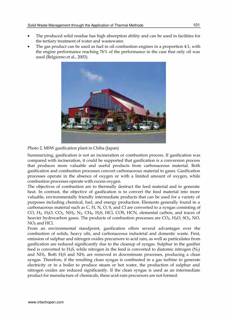
Photo 2. MSW gasification plant in Chiba (Japan)
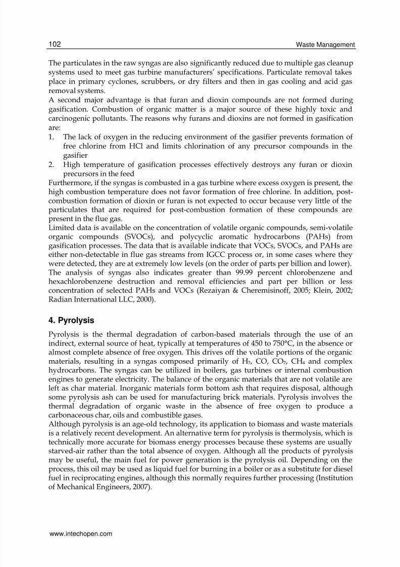
Summarizing, gasification is not an incineration or combustion process. If gasification wascompared with incineration, it could be supported that gasification is a conversion processthat produces more valuable and useful products from carbonaceous material. Bothgasification and combustion processes convert carbonaceous material to gases. Gasificationprocesses operate in the absence of oxygen or with a limited amount of oxygen, whilecombustion processes operate with excess oxygen.The objectives of combustion are to thermally destruct the feed material and to generateheat. In contrast, the objective of gasification is to convert the feed material into morevaluable, environmentally friendly intermediate products that can be used for a variety ofpurposes including chemical, fuel, and energy production. Elements generally found in acarbonaceous material such as C, H, N, O, S, and Cl are converted to a syngas consisting ofCO, H2, H2O, CO2, NH3, N2, CH4, H2S, HCl, COS, HCN, elemental carbon, and traces ofheavier hydrocarbon gases. The products of combustion processes are CO2, H2O, SO2, NO,
NO2 and HCl.From an environmental standpoint, gasification offers several advantages over thecombustion of solids, heavy oils, and carbonaceous industrial and domestic waste. First,emission of sulphur and nitrogen oxides precursors to acid rain, as well as particulates fromgasification are reduced significantly due to the cleanup of syngas. Sulphur in the gasifierfeed is converted to H2S, while nitrogen in the feed is converted to diatomic nitrogen (N2)and NH3. Both H2S and NH3 are removed in downstream processes, producing a cleansyngas. Therefore, if the resulting clean syngas is combusted in a gas turbine to generateelectricity or in a boiler to produce steam or hot water, the production of sulphur andnitrogen oxides are reduced significantly. If the clean syngas is used as an intermediateproduct for manufacture of chemicals, these acid-rain precursors are not formed.
www.intechopen.com
8/13/2019 InTech-Solid Waste Management Through the Application of Thermal Methods
http://slidepdf.com/reader/full/intech-solid-waste-management-through-the-application-of-thermal-methods 14/37
Waste Management102
The particulates in the raw syngas are also significantly reduced due to multiple gas cleanupsystems used to meet gas turbine manufacturers’ specifications. Particulate removal takesplace in primary cyclones, scrubbers, or dry filters and then in gas cooling and acid gasremoval systems.
A second major advantage is that furan and dioxin compounds are not formed duringgasification. Combustion of organic matter is a major source of these highly toxic andcarcinogenic pollutants. The reasons why furans and dioxins are not formed in gasificationare:1. The lack of oxygen in the reducing environment of the gasifier prevents formation of
free chlorine from HCl and limits chlorination of any precursor compounds in thegasifier
2. High temperature of gasification processes effectively destroys any furan or dioxinprecursors in the feed
Furthermore, if the syngas is combusted in a gas turbine where excess oxygen is present, thehigh combustion temperature does not favor formation of free chlorine. In addition, post-
combustion formation of dioxin or furan is not expected to occur because very little of theparticulates that are required for post-combustion formation of these compounds arepresent in the flue gas.Limited data is available on the concentration of volatile organic compounds, semi-volatileorganic compounds (SVOCs), and polycyclic aromatic hydrocarbons (PAHs) fromgasification processes. The data that is available indicate that VOCs, SVOCs, and PAHs areeither non-detectable in flue gas streams from IGCC process or, in some cases where theywere detected, they are at extremely low levels (on the order of parts per billion and lower).The analysis of syngas also indicates greater than 99.99 percent chlorobenzene andhexachlorobenzene destruction and removal efficiencies and part per billion or lessconcentration of selected PAHs and VOCs (Rezaiyan & Cheremisinoff, 2005; Klein, 2002;
Radian International LLC, 2000).
4. Pyrolysis
Pyrolysis is the thermal degradation of carbon-based materials through the use of anindirect, external source of heat, typically at temperatures of 450 to 750°C, in the absence oralmost complete absence of free oxygen. This drives off the volatile portions of the organicmaterials, resulting in a syngas composed primarily of H2, CO, CO2, CH4 and complexhydrocarbons. The syngas can be utilized in boilers, gas turbines or internal combustionengines to generate electricity. The balance of the organic materials that are not volatile areleft as char material. Inorganic materials form bottom ash that requires disposal, although
some pyrolysis ash can be used for manufacturing brick materials. Pyrolysis involves thethermal degradation of organic waste in the absence of free oxygen to produce acarbonaceous char, oils and combustible gases.Although pyrolysis is an age-old technology, its application to biomass and waste materialsis a relatively recent development. An alternative term for pyrolysis is thermolysis, which istechnically more accurate for biomass energy processes because these systems are usuallystarved-air rather than the total absence of oxygen. Although all the products of pyrolysismay be useful, the main fuel for power generation is the pyrolysis oil. Depending on theprocess, this oil may be used as liquid fuel for burning in a boiler or as a substitute for dieselfuel in reciprocating engines, although this normally requires further processing (Institutionof Mechanical Engineers, 2007).
www.intechopen.com

8/13/2019 InTech-Solid Waste Management Through the Application of Thermal Methods
http://slidepdf.com/reader/full/intech-solid-waste-management-through-the-application-of-thermal-methods 15/37
Solid Waste Management through the Application of Thermal Methods 103
The reactions taking place initially are decomposition ones, where organic components oflow volatility are converted into other more volatile ones:
CxHy→ CcHd + CmHn (9)
Moreover, at the early stages of pyrolysis process, reactions occurring include condensation,hydrogen removal and ring formation reactions that lead to the formation of solid residuefrom organic substances of low volatility:
CxHy→ CpHq + H2 + coke (10)
In the case of existence of oxygen, CO and CO2 are produced or the interaction with water ispossible. The produced coke can be vaporized intoΟ2 and CO2.The pyrolysis products can be liquid, solid and gaseous. The majority of the organicsubstances in waste are subjected to pyrolysis by 75 – 90 % into volatile substances and by10 – 25 % to solid residue (coke). However, due to the existence of humidity and inorganic
substances, the quantity of volatile substances varies from 60 to 70% and the coke between30 and 40%.In order to achieve the successful operation of a pyrolysis facility, continuous control isrequired due to the complex processes taking place during the method development.Moreover, solid waste with no major composition variation that does not include metals andglass has to be fed on continuous basis (use of waste after successful implementation ofseparation at source or mechanical separation). In addition, special care is needed about
SolidCarbon that is incorporated into several inert
products-
Gas Dust particles, CO, CO2, CH4, H2 700 m3 off-gases / tone of waste
LiquidCH3COOH, CH3COCH3, CH3OH, complex
oxygenised H/C
Table 1. Brief description of the solid, liquid and gas products from the operation of apyrolysis unit
Pyrolysis temperature (οC)% v/v gascomposition 500 650 815 926
CO 33.6 30.5 34.1 35.3
CO2 44.8 31.8 20.6 18.3
H2 5.6 16.5 28.6 32.4
CH4 12.5 15.9 28.6 32.4
C2H6 3.0 3.1 0.8 1.1
C2H4 0.5 2.2 2.2 2.4
Calorific Value(btu/St/t)
312 403 392 385
Table 2. Composition of the produced gas at different pyrolysis temperatures
www.intechopen.com
8/13/2019 InTech-Solid Waste Management Through the Application of Thermal Methods
http://slidepdf.com/reader/full/intech-solid-waste-management-through-the-application-of-thermal-methods 16/37
Waste Management104
whether the liquid products satisfy the specifications of commercial fuel (mainly due to thehumidity within these products).The product proportions depend on the waste nature, the temperature conditions and thetreatment time.
The products produced from pyrolysing materials are a solid residue and a synthetic gas(syngas), while some of the volatile components form tars and oils can be removed andreused. The solid residue (sometimes described as a char) is a combination of non-combustible materials and carbon. The syngas is a mixture of gases (combustibleconstituents include carbon monoxide, hydrogen, methane and a broad range of otherVOCs). A proportion of these can be condensed to produce oils, waxes and tars. The syngastypically has a net calorific value of between 10 and 20 MJ/Nm3. If required, thecondensable fraction can be collected by cooling the syngas, potentially for use as liquid fuel(Gidarakos 2006).
Typical Pyrolysis Facility
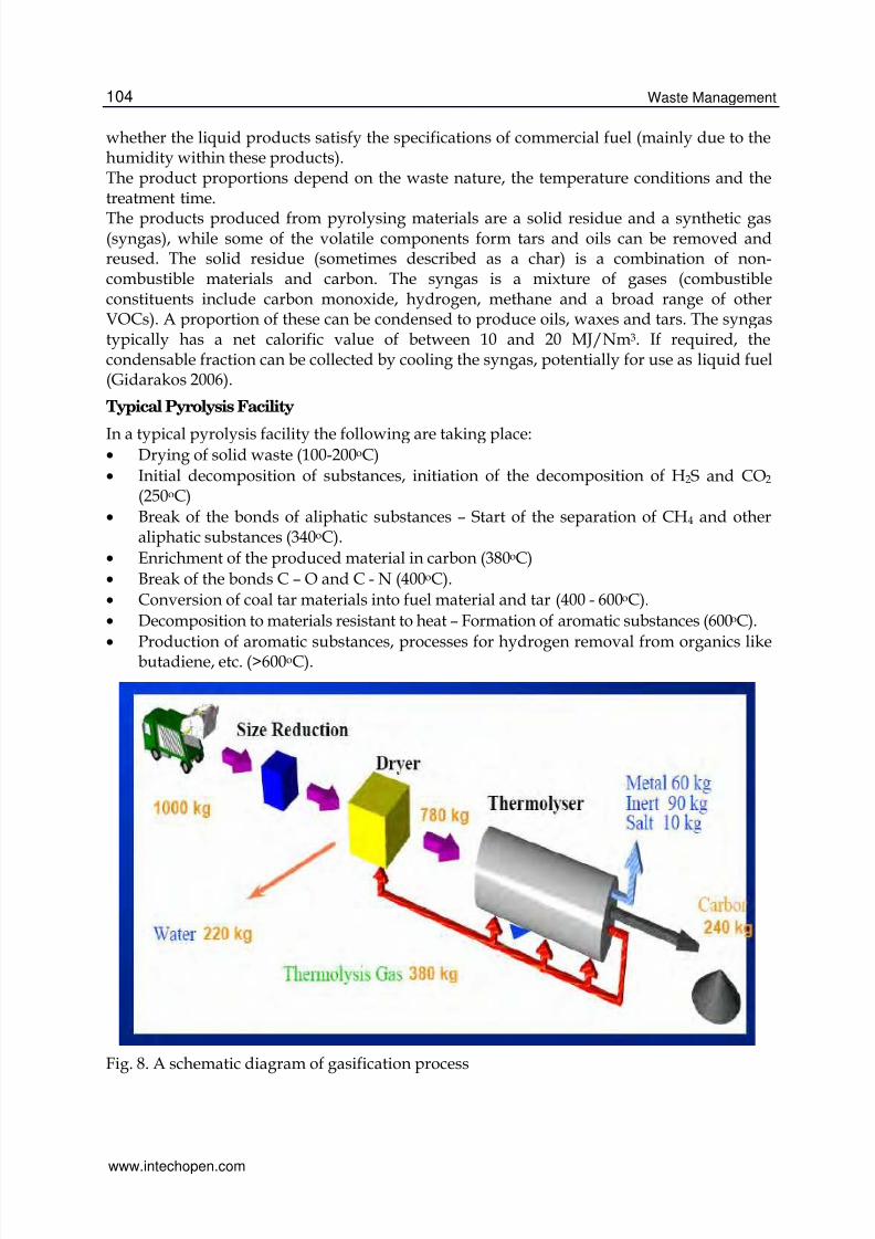
In a typical pyrolysis facility the following are taking place:• Drying of solid waste (100-200οC)
• Initial decomposition of substances, initiation of the decomposition of H2S and CO2 (250οC)
• Break of the bonds of aliphatic substances – Start of the separation of CH4 and otheraliphatic substances (340οC).
• Enrichment of the produced material in carbon (380οC)
• Break of the bonds C – O and C - N (400οC).
• Conversion of coal tar materials into fuel material and tar (400 - 600οC).
• Decomposition to materials resistant to heat – Formation of aromatic substances (600οC).
• Production of aromatic substances, processes for hydrogen removal from organics likebutadiene, etc. (>600οC).
Fig. 8. A schematic diagram of gasification process
www.intechopen.com

8/13/2019 InTech-Solid Waste Management Through the Application of Thermal Methods
http://slidepdf.com/reader/full/intech-solid-waste-management-through-the-application-of-thermal-methods 17/37
Solid Waste Management through the Application of Thermal Methods 105
The main advantages of pyrolysis in comparison to incineration are:
• The decomposition temperature is lower than the incineration temperature, so thethermal distress of the whole facility is less intense than in incineration.
• The decomposition takes place in reducing atmosphere and not in oxidizing like in
incineration. The demand for less oxygen is also the reason for less air emissions in thecase of pyrolysis.
• The ash content in carbon is much higher than in the case of incineration.
• The metals that are included in waste are not oxidized during pyrolysis and havehigher commercial value.
• The produced gas is at different hearth and probably other site from the pyrolyticreactor.
• No ash is produced from the combustion of the pyrolysis gas and the cleaning of theoff-gas is a simpler process.
• The initial waste volume is reduced at higher level in comparison with the incineration.
The main disadvantages of pyrolysis include:• The big problem of this technique is that pre-treatment is required including cuttingand separation of waste prior to pyrolysis which can increase the cost for theinstallation and operation of such units substantially.
• The pyrolysis products cannot be disposed without further treatment.
• The facilities for cleaning the gases and wastewater require extremely high cost.
• At present, the application of the method at large scale is limited. Nevertheless, theprospects for reactors of average temperature with the form of rotary drum or fluidizedbed seem to be better.
5. Plasma technology
5.1 GeneralPlasma refers to every gas of which at least a percentage of its atoms or molecules ispartially or totally ionized. In a plasma state of matter, the free electrons occur at reasonablyhigh concentrations and the charges of electrons are balanced by positive ions. As a result,plasma is quasi-neutral. It is generated from electric discharges, e.g. from the passage ofcurrent (continuous, alternate or high frequency) through the gas and from the use of thedissipation of resistive energy in order to make the gas sufficiently hot. Plasma ischaracterized as the fourth state of matter and differs from the ideal gases, because it ischaracterized by ‘collective phenomena’. ‘Collective phenomena’ originate from the widerange of Coulomb forces. As a result, the charged particles do not interact only with
neighbouring particles through collisions, but they also bear the influence of an averageelectromagnetic field, which is generated by the rest charges. In a large number ofphenomena, collisions do not play important role, as ‘collective phenomena’ take placemuch faster than the characteristic collision time (Blahos, 2000).Plasma technology can be used as a tool for green chemistry and waste management(Mollah et al., 2000). Thermal plasmas have the potential to play an important role in avariety of chemical processes. They are characterized by high electron density and lowelectron energy. Compared to most gases even at elevated temperatures and pressures, thechemical reactivity and quenching rates that are characteristic of these plasmas is far greater.Plasma technology is very drastic due to the presence of highly reactive atomic and ionicspecies and the achievement of higher temperatures in comparison with other thermal
www.intechopen.com

8/13/2019 InTech-Solid Waste Management Through the Application of Thermal Methods
http://slidepdf.com/reader/full/intech-solid-waste-management-through-the-application-of-thermal-methods 18/37
Waste Management106
methods. In fact, the extremely high temperatures (several thousands degrees in Celsiusscale) occur only in the core of the plasma, while the temperature decreases substantially inthe marginal zones (Leal-Quirós, 2004; Gomez et al., 2009).Five distinct categories of processes are used as the basis for the plasma systems catering for
waste management. These are:• Plasma pyrolysis (Huang & Tang, 2007; Sheng et al., 2008)
• Plasma combustion (also called plasma incineration or plasma oxidation)
• Plasma vitrification
• Plasma gasification in two different variants (Malkow, 2004)
• Plasma polishing using plasma to clean off-gasesThe proportion of air used during waste treatment and the nature of the output products areprimary differences between the aforementioned plasma processes. In practice, commercialprocesses can be designed to allow two or more of these to occur within a single integratedsystem (Juniper 2006).Plasma gasification is the most common plasma process. It is an advanced gasificationprocess which is performed in an oxygen-starved environment to decompose organic solidwaste into its basic molecular structure. Plasma gasification does not combust the waste asincinerators do. It converts the organic waste into a fuel gas that still contains all thechemical and heat energy from the waste. Also, it converts the inorganic waste into an inertvitrified glass.Electricity is fed to a torch, which has two electrodes, creating an arc. Inert gas is passedthrough the arc, heating the process gas to internal temperatures as high as 25,000 degreesFahrenheit. The following diagram illustrates how the plasma torch operates.
Fig. 9. Illustration of the operation of a plasma torch (Westinghouse)
The temperature a few feet from the torch can be as high as 5,000-8,000°F. Because of thesehigh temperatures waste is completely destroyed and broken down into its basic elementalcomponents. At these high temperatures all metals become molten and flow out the bottom ofthe reactor. Inorganics, such as silica, soil, concrete, glass, gravel, etc. are vitrified into glassand flow out the bottom of the reactor. There is no ash remaining to go back to a landfill.Mixed solid waste is shredded and fed into a reactor where an electric discharge similar to a
lightning (the plasma) converts the organic fraction into synthesis gas and the inorganic
www.intechopen.com

8/13/2019 InTech-Solid Waste Management Through the Application of Thermal Methods
http://slidepdf.com/reader/full/intech-solid-waste-management-through-the-application-of-thermal-methods 19/37
8/13/2019 InTech-Solid Waste Management Through the Application of Thermal Methods
http://slidepdf.com/reader/full/intech-solid-waste-management-through-the-application-of-thermal-methods 20/37
Waste Management108
Fig. 10. A schematic diagram of plasma process
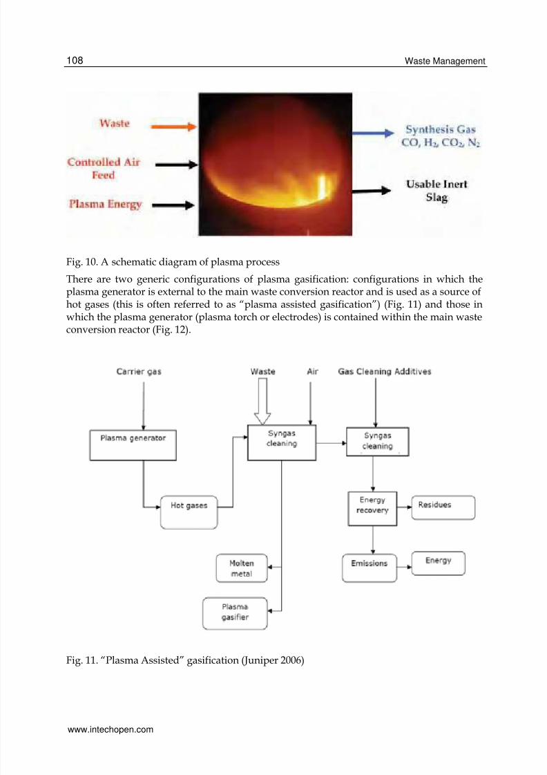
There are two generic configurations of plasma gasification: configurations in which theplasma generator is external to the main waste conversion reactor and is used as a source ofhot gases (this is often referred to as “plasma assisted gasification”) (Fig. 11) and those inwhich the plasma generator (plasma torch or electrodes) is contained within the main wasteconversion reactor (Fig. 12).
Fig. 11. “Plasma Assisted” gasification (Juniper 2006)
www.intechopen.com

8/13/2019 InTech-Solid Waste Management Through the Application of Thermal Methods
http://slidepdf.com/reader/full/intech-solid-waste-management-through-the-application-of-thermal-methods 21/37
Solid Waste Management through the Application of Thermal Methods 109
Photo 3. “Plasma Assisted” gasification unit owned by Hitachi Metals with treatmentcapacity of 200 tones of municipal solid waste and automobile shredder residue per day inUtashinai in Japan (Circeo, 2007)
Fig. 12. Plasma gasification (Juniper 2006)
5.2 The case of the pilot gasification / vitrification unit in Greece
The first attempt to apply gasification process in Greece was made by the Unit of
Environmental Science & Technology of the National Technical University of Athens, with a
unit that was installed in Mykonos in order to treat all types of waste generated on the
island. The scope was to investigate the use of this innovative technique in an isolated area
like an island in order to provide a solution to the overall management of waste. General
views of the whole demonstration facility are available below:
www.intechopen.com

8/13/2019 InTech-Solid Waste Management Through the Application of Thermal Methods
http://slidepdf.com/reader/full/intech-solid-waste-management-through-the-application-of-thermal-methods 22/37
Waste Management110
Photo 4. General view of the demonstration gasification / vitrification unit
Photo 5. Another general view of the demonstration gasification / vitrification unit
The primary waste feeding system consists of a hopper intended for feed of solid materialhaving maximum moisture content of 50% and a maximum particle size of 2.5 cm. Thescrew conveyor solid feeder has a maximum capacity of about 85 kg/h of waste and the
www.intechopen.com

8/13/2019 InTech-Solid Waste Management Through the Application of Thermal Methods
http://slidepdf.com/reader/full/intech-solid-waste-management-through-the-application-of-thermal-methods 23/37
Solid Waste Management through the Application of Thermal Methods 111
feeding capacity varies depending on the feed waste bulk density. The feed rate isadjustable by varying the speed of the screw conveyor. Waste is manually loaded into thehopper connected to the screw conveyor. The feed rate is continuous and very steady,compared to a hydraulic feeder.
Waste is fed from a hopper through a screw feeder to the top of the furnace and droppingdown is passing through the very hot and free of oxygen region between the two electrodes.
Photo 6. Feeding system
The furnace is comprised of a crucible, with approximately 130 litters capacity. It alsoincludes a start-up natural gas burner for preheating and idle operation, a port forgasification air injection, a water-cooling mechanism for the graphite electrodes, an externalsurface water-cooling for the furnace walls and a tapping hole for periodical or continuous
slag removal. During the operation of the plasma unit, the bottom part of the furnacecontains the molten slag, while the upper section of it contains the process gases and is linedwith a suitable high-temperature refractory. The required gasification air fed to the furnaceis supplied by a compressed air system. Adjusting the valves on the compressed air line cancontrol the flow rate.
Photo 7. Gasification / vitrification furnace
www.intechopen.com

8/13/2019 InTech-Solid Waste Management Through the Application of Thermal Methods
http://slidepdf.com/reader/full/intech-solid-waste-management-through-the-application-of-thermal-methods 24/37
Waste Management112
Fig. 13. Plasma Gasification / Vitrification Process
In the pilot unit the furnace in which waste gasification is taking place is preheated at 600-800°C by burning propane in its interior. After preheating, two cylindrical graphiteelectrodes are inserted in the furnace and their ends are approached to a close distance. Twographite electrodes are used to supply an electrical arc to the furnace. The current flowsfrom the anode (+) to the molten bath and from the bath to the cathode (-). The cathode isgrounded at zero (0) potential.Graphite electrodes with male/female threads are used. The electrode dimensions were 7.6
cm in diameter and 106.7 in length. Electrodes are installed with the female end down, in
Photo 8. Preheating
Synthesis Waste
MoltenSla
Iron Heel
--
UntreatedWaste
www.intechopen.com

8/13/2019 InTech-Solid Waste Management Through the Application of Thermal Methods
http://slidepdf.com/reader/full/intech-solid-waste-management-through-the-application-of-thermal-methods 25/37
Solid Waste Management through the Application of Thermal Methods 113
order to avoid dust accumulation in the threads. Two electrodes were screwed together oneach side (anode and cathode) and are mounted on flexible joints, which allow them to bemoved over the slag pool and improve mixing. The mechanism also permits the electrodes’extension into the furnace to be adjusted during operation (Carabin & Holcroft, 2005;
Carabin et al., 2004; Gagnon & Carabin, 2006).The DC power supply for the electrodes has a maximum power output of 200 KVA (Plasmaarc power supply, input: 600 VAC-3φ-60HZ, 3 X 200A fuses).
Photo 9. Movement Mechanism of the graphite electrode
Photo 10. Camera recording what is happening in the furnace
www.intechopen.com

8/13/2019 InTech-Solid Waste Management Through the Application of Thermal Methods
http://slidepdf.com/reader/full/intech-solid-waste-management-through-the-application-of-thermal-methods 26/37
Waste Management114
Photo 11. Tapping inert slag (Pyrogenesis Canada Inc, Montreal, Canada)
Then, a high voltage is applied between them producing an electrical arc which is raising
locally the temperature up to values as high as 5,000 °C and creating a plasma atmosphere.
Air is not permitted to enter the furnace. Under these conditions it is ensured that from the
volatile part of the wastes syngas is produced consisting mainly of H2, CO, CO2 and H2O
and containing in very low proportions H2S and HCl, but without significant presence of
NOx. A camera is installed in front of a window on the top of the furnace, connected with a
laptop, by which we can watch or make video recording of the electrical arc and thedecomposition of the organic matter taking place in the interior of the furnace.
Photo 12. No arc Photo 13. Plasma arc
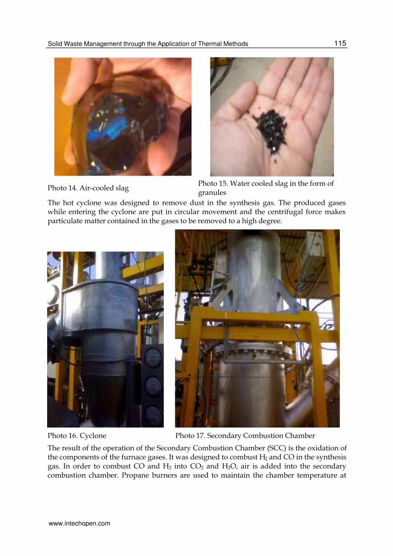
The slag could be tapped out periodically from the tap hole located on the front side of the
crucible, close to the bottom of the furnace. The slag was either poured in a slag mold to
form ingots (photo 14) or quenched in a water tank to produce granulated slag (photo 15).
The inorganic part of the wastes used is melted, drops to the bottom of the furnace and from
time to time is removed through a hole in the lower part of the furnace, is collected to a fire
resistant pan and is taken to the laboratory for analysis and investigation of its toxicity.
www.intechopen.com
8/13/2019 InTech-Solid Waste Management Through the Application of Thermal Methods
http://slidepdf.com/reader/full/intech-solid-waste-management-through-the-application-of-thermal-methods 27/37
Solid Waste Management through the Application of Thermal Methods 115
Photo 14. Air-cooled slagPhoto 15. Water cooled slag in the form of
granulesThe hot cyclone was designed to remove dust in the synthesis gas. The produced gaseswhile entering the cyclone are put in circular movement and the centrifugal force makesparticulate matter contained in the gases to be removed to a high degree.
Photo 16. Cyclone Photo 17. Secondary Combustion Chamber
The result of the operation of the Secondary Combustion Chamber (SCC) is the oxidation ofthe components of the furnace gases. It was designed to combust H2 and CO in the synthesisgas. In order to combust CO and H2 into CO2 and H2O, air is added into the secondarycombustion chamber. Propane burners are used to maintain the chamber temperature at
www.intechopen.com
8/13/2019 InTech-Solid Waste Management Through the Application of Thermal Methods
http://slidepdf.com/reader/full/intech-solid-waste-management-through-the-application-of-thermal-methods 28/37
Waste Management116
1,100°C. The operator can check local regulations to determine the required temperature insecondary combustion chamber. This temperature is required to fully combust CO and H2 ina region where no hazardous by-products are created. In normal operation, the gasresidence time in the secondary combustion chamber is about two seconds. A single blower
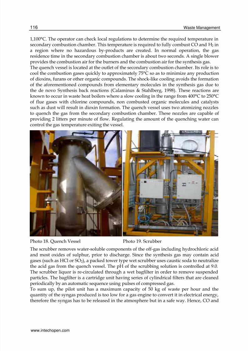
provides the combustion air for the burners and the combustion air for the synthesis gas.The quench vessel is located at the outlet of the secondary combustion chamber. Its role is tocool the combustion gases quickly to approximately 75°C so as to minimize any productionof dioxins, furans or other organic compounds. The shock-like cooling avoids the formationof the aforementioned compounds from elementary molecules in the synthesis gas due tothe de novo Synthesis back reactions (Calaminus & Stahlberg, 1998). These reactions areknown to occur in waste heat boilers where a slow cooling in the range from 400°C to 250°Cof flue gases with chlorine compounds, non combusted organic molecules and catalystssuch as dust will result in dioxin formation. The quench vessel uses two atomizing nozzlesto quench the gas from the secondary combustion chamber. These nozzles are capable ofproviding 2 litters per minute of flow. Regulating the amount of the quenching water cancontrol the gas temperature exiting the vessel.
Photo 18. Quench Vessel Photo 19. Scrubber
The scrubber removes water-soluble components of the off-gas including hydrochloric acidand most oxides of sulphur, prior to discharge. Since the synthesis gas may contain acidgases (such as HCl or SO2), a packed tower type wet scrubber uses caustic soda to neutralizethe acid gas from the quench vessel. The pH of the scrubbing solution is controlled at 9.0.The scrubber liquor is re-circulated through a wet bagfilter in order to remove suspendedparticles. The bagfilter is a cartridge unit having series of cylindrical filters that are cleanedperiodically by an automatic sequence using pulses of compressed gas.To sum up, the pilot unit has a maximum capacity of 50 kg of waste per hour and thequantity of the syngas produced is too low for a gas engine to convert it in electrical energy,therefore the syngas has to be released in the atmosphere but in a safe way. Hence, CO and
www.intechopen.com

8/13/2019 InTech-Solid Waste Management Through the Application of Thermal Methods
http://slidepdf.com/reader/full/intech-solid-waste-management-through-the-application-of-thermal-methods 29/37
Solid Waste Management through the Application of Thermal Methods 117
H2 have to be transformed to CO2 and H2O and for this purpose the SCC has been added inthe installation, which is maintained at high temperature by combusting propane with airand in which CO and H2 are burnt to CO2 and H2O. The SCC in our installation is situatedafter the furnace and between the two units is interceded a cyclone to remove the solid
particles. After the SCC the flue gases are objected to quenching by coming in contact with abig quantity of cold water and this takes place in a pipe where flue gases and cooling waterare moving opposite each other. After quenching, the flue gases are passing for cleaningthrough a scrubber with NaOH solution, then through a filter and finally before they arereleased to the atmosphere via a stack are cooled in a heat exchanger to condense andrecirculate the maximum quantity of water vapors (Moustakas et al., 2005; Moustakas et al.,2008).The control and monitoring of the operation of the whole system is made through a laptopby a special software program. The main pages of the software are as follows:
Fig. 14. Main page of the software system for the control of the operation of the unit
Fig. 15. Page of the software system for the control of the furnace
www.intechopen.com

8/13/2019 InTech-Solid Waste Management Through the Application of Thermal Methods
http://slidepdf.com/reader/full/intech-solid-waste-management-through-the-application-of-thermal-methods 30/37
Waste Management118
Fig. 16. Page of the software system for the control of the Secondary Combustion Chamber
Fig. 17. Page of the software system for the controlof the off-gas cleaning systems
Two gas analyzers for on line measurements are also necessary for the full monitoring of theoperation of the gasification / vitrification plant, one between the furnace and the SCC forthe determination of the syngas composition and the other one in the outlet stack of the flue
gases to determine their composition and avoid air pollution.The main consumables needed for its operation are water, diesel to run the generator for thepower supply of the installation, propane as well as the graphite electrodes.Regarding the produced slag, after the vitrification, the slag was studied by X-ray fluorescenceanalysis for the determination of chemical composition, by conventional Bragg-Brentano X-raydiffraction (XRD) for the evaluation of crystalline phases formed and by scanning electronmicroscope (SEM) equipped with energy-dispersive X-ray (EDX) elemental analysis formicrostructure/morphology observation and compositions (Kuo et al., 2009).The amorphous or crystalline nature of vitreous materials was established by X-ray diffraction(XRD). Samples were crushed to fine powder in an agate mortar and then were scanned with
www.intechopen.com

8/13/2019 InTech-Solid Waste Management Through the Application of Thermal Methods
http://slidepdf.com/reader/full/intech-solid-waste-management-through-the-application-of-thermal-methods 31/37
Solid Waste Management through the Application of Thermal Methods 119
CuKα radiation from 10 ≤ 2θ ≤ 70° at a scanning speed of 0.3°/min, using a Siemens D5000powder X-ray diffraction unit, operating at 30 mA and 40 kV. The XRD analysis patterns areshown in Fig. 18 and 19 for water quenched and air-cooled slag respectively.
Fig. 18. XRD of the water quenched slag
Fig. 19. XRD of the air-cooled slag
The XRD pattern (Fig. 18) indicates that the water quenched slag is composed of mainlyamorphous and traces of crystalline phase. Crystalline phases were identified by comparingintensities and positions of Bragg peaks with those listed in the Joint Committee on PowderDiffraction Standards (JCPDS) data files. The crystalline phases that could be identified werecristobalite (SiO2), corundum (Al2O3), mayenite (Ca12Al14O33) and iron aluminum oxide(Fe1.006Al1.994O4).The XRD pattern of the air cooled slag revealed an amorphous phase and no crystallinestructures or phases are observed (Fig. 19). The formation of glassy amorphous structures
www.intechopen.com
8/13/2019 InTech-Solid Waste Management Through the Application of Thermal Methods
http://slidepdf.com/reader/full/intech-solid-waste-management-through-the-application-of-thermal-methods 32/37
Waste Management120
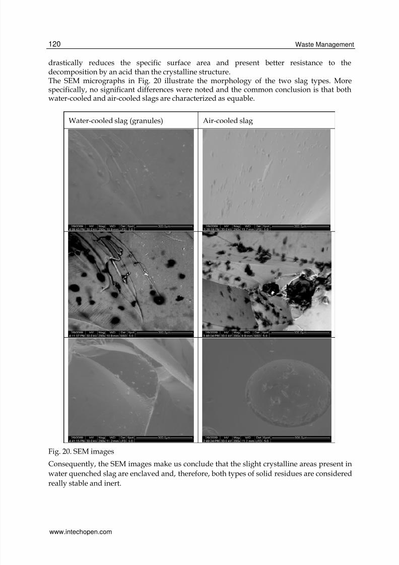
drastically reduces the specific surface area and present better resistance to thedecomposition by an acid than the crystalline structure.The SEM micrographs in Fig. 20 illustrate the morphology of the two slag types. Morespecifically, no significant differences were noted and the common conclusion is that both
water-cooled and air-cooled slags are characterized as equable.
Water-cooled slag (granules) Air-cooled slag
Fig. 20. SEM images
Consequently, the SEM images make us conclude that the slight crystalline areas present in
water quenched slag are enclaved and, therefore, both types of solid residues are considered
really stable and inert.
www.intechopen.com

8/13/2019 InTech-Solid Waste Management Through the Application of Thermal Methods
http://slidepdf.com/reader/full/intech-solid-waste-management-through-the-application-of-thermal-methods 33/37
Solid Waste Management through the Application of Thermal Methods 121
On the basis of the primary results derived from the operation of the demonstrationgasification facility in Mykonos and elsewhere, plasma gasification is a promisingtechnology especially in the case of isolated areas, such as islands. More specifically,
• The method is characterized by relatively low air emissions that are not harmful for the
environment. The release of polluting substances, such as SO2, metals, dioxins will be atmuch lower levels than conventional thermal techniques like incineration.
• Gasification can be used for the management of all types of waste, both hazardous andnon hazardous waste. Such facilities can handle municipal, toxic and hospital waste ormixtures of them
• Plasma gasification is not an incineration process. As a result, the disadvantages of theincineration are avoided.
• No ash or other by-products, such as biomass that has to be disposed at landfills afterthe treatment. In this way, there is no disposal cost provided that there is market for thevitrified slag.
• The material recovery is greater than in any other thermal technique. Instead ofconsuming raw materials, this method produces slag that can be used as material in avariety of applications, such as construction works.
• Energy recovery is higher than any other waste management practice. Therefore, theincome for energy sale can be significant. It is supported that in the case of plasmagasification the generation of net electricity (steam turbine power generation) from 1tone of municipal solid waste could reach the value of 816kWh. The relevant netelectricity from pyrolysis (Mitsui R21 Technology) is 571 kWh and 544 kWh from mass-burn technology (Circeo 2007).
• The emissions at air, water and soil are lower than in other processes.
• Plasma gasification can be used for energy production from non gas fuels.
• The releases to the atmosphere during the production of electrical energy are similarwith those of facilities with natural gas.
• Since every C-based substance that exists in the plasma gasifier is converted to gas, eachof them can be used as fuel (Lemmens et al., 2007).
6. Conclusions
The energy utilization from waste can be achieved with the application of different thermaltechnologies (anaerobic digestion, a biological waste management method, can also result inenergy recovery form waste). The basic operation principles that should apply to all thermaltreatment facilities for municipal solid waste are:
1. Steady operation conditions.2. Easiness for adaptation to rough changes of the composition and the quantity of feedstuff.3. Flexibility for adaptation to the variations of the composition and the quantity of the
used fuel.4. Full control of the pollutants in the emissions.5. Maximization of the utilization of the thermal energy, mainly for the production of
electrical energy.6. Minimization of the capital and operation cost.Summarizing the main characteristics of the common thermal techniques for wastemanagement, the following table presents the basic products and the main operationconditions.
www.intechopen.com

8/13/2019 InTech-Solid Waste Management Through the Application of Thermal Methods
http://slidepdf.com/reader/full/intech-solid-waste-management-through-the-application-of-thermal-methods 34/37
Waste Management122
Parameter Incineration Pyrolysis Gasification
Operation conditions
Temperature οC 800-1,450 250-700 500-1,600
Pressure (bar) 1 1 1-45
Atmosphere Air Inert/Nitrogen Gasification factor:Ο2, Η2Ο
Stoichiometricrelation
>1 0 <1
Products
Gas Phase CO2, Η2Ο, O2, N2 H2, CO, H2O, N2, H/C H2, CO, CO2, CH4,H2O, N2
Solid Phase Ash, Scoria Ash, Scoria Ash, Scoria
Liquid Phase Pyrolysis Oils & H2O
Table 4. Parameters of typical operation conditions & products of the common thermalmanagement practices
Thermal waste management methods should be applied together with separation at sourceof all materials that can be recycled in order to maximize material recovery from waste. Theadvantages of thermal methods in waste treatment are summarized as follows:• Reduction of the weight and volume of the treated waste: The final solid residues have
weight that varies from 3 to 20% in relation to the initial weight of waste, depending onthe technology that is used. Gasification and pyrolysis result in lower quantities of solid
residues comparing to incineration.• Absence of pathogenic factors in the products:
• The products of thermal treatment, due to the high temperatures that aredeveloped, are characterized from complete absence of pathogenic factors.
• Demand for limited areas:• The thermal treatment units are characterized by low demands for land for their
installation.• The pyrolysis and gasification processes require less space in relation to incineration.
• Utilization of the energy content of waste:• Through the thermal treatment technologies, the exploitation of the energy content
of waste is possible.
• This energy can be either electric or thermal energy.• Reduction of the burden paused to the landfill sites and consequent increase of their
lifetime.• Extraction of the organic fraction of municipal waste from landfill sites, as required by
the relevant legislative framework (Directive 1999/31/EC).Indicative disadvantages of the application of thermal methods are the following:• Relatively high capital cost:
• Higher than that of other technologies for the management of municipal waste.• Significant part of the total capital cost, especially for the case of incineration, is
spent on antipollution measures.• Increased operation cost
www.intechopen.com

8/13/2019 InTech-Solid Waste Management Through the Application of Thermal Methods
http://slidepdf.com/reader/full/intech-solid-waste-management-through-the-application-of-thermal-methods 35/37
Solid Waste Management through the Application of Thermal Methods 123
• In general, the thermal management techniques are characterized by relatively highoperation cost. The cost is reduced substantially as the capacity of the plant increases.
• Demand for high quantities of waste:• Especially for the case of incineration – combustion, a minimum capacity is
required so that the units are financially feasible. Estimated minimum servedpopulation from incineration facilities is 100,000 inhabitants (around 50,000 tonesof waste annually). Gasification and pyrolysis can be applied for much lower wastequantities (around 15,000 tones of waste per year)
• Need for specialized personnel.Regarding the first pilot application for waste gasification in Greece, an EU country where thethermal management of municipal waste is not applied, the main advantages of the processinvolve: good environmental performance, production of more than 500 KWh net of electricityper tone of waste treated, no by-products going to landfill. Therefore, it is hoped that thisattempt will lead to full scale gasification facility in Mykonos, which will cater for the needs ofthe whole island treating municipal as well as other waste streams (e.g. hospital waste), with
total capacity in the range between 10,000 and 15,000 tones per year. The fulfilment of thewhole project will constitute innovative achievement at European level and will be an effectivewaste management success story for isolated areas and especially islands.
7. References
Allsopp, M., Costner, P. & Johnston, P. (2001). Incineration and human health, State of knowledge of the impacts of waste incinerators on human health, ISBN: 90-73361-69,9,Greenpeace Research Laboratories, University of Exeter, UK
Autret, E., Berthier, F., Luszezanec, A. & Nicolas, F. (2007). Incineration of municipal andassimilated wastes in France: Assessment of latest energy and material recovery
performances, Journal of Hazardous Materials B139, 569-574Belgiorno, V., De Feo, G., Rocca, C. D. & Napoli, R.M.A. (2003). Energy from gasification ofsolid wastes, Waste Management 23, 1-15
Blahos, L. (2000). Plasma Physics, the Fourth State of Matter, Giolas Editions, 1–12Calaminus, B. & Stahlberg, R. (1998). Continuous in-line gasification/ vitrification process
for thermal waste treatment: process technology and current status of projects,Waste Management 18 (1998) 547-556
Carabin, P. & Holcroft, G. (2005). Plasma resource recovery technology converting waste toenergy and valuable products, in: Proceedings of the 13th Annual North AmericanWaste to Energy Conference, NAWTEC13, 71–79, Article number NAWTEC13-3155
Carabin, P., Palumbo, E. & Alexakis, T. (2004). Two-stage plasma gasification of waste, in:Proceedings of the 23rd International Conference on Incineration and ThermalTreatment Technologies, Phoenix, AZ, USA, May 10–14.
Circeo, L. (2007). Plasma Arc Gasification of Municipal Solid Waste, EPA Region 4 Cleanand Sustainable Energy Conference Embassy Suites Hotel at Centennial OlympicPark, Atlanta, GA
Deriziotis P. (2004). Substance and perceptions of environmental impacts of dioxinemissions. M.S. thesis, Columbia University (data by U.S. EPA)
Directive 2000/76/EC of the European Parliament and of the Council of 4 December 2000 onthe incineration of waste.
European Commission, (2006). Integrated Pollution Prevention and Control Reference Documenton the Best Available Techniques for Waste Incineration
www.intechopen.com

8/13/2019 InTech-Solid Waste Management Through the Application of Thermal Methods
http://slidepdf.com/reader/full/intech-solid-waste-management-through-the-application-of-thermal-methods 36/37
Waste Management124
Gagnon, J. & Carabin, P. (2006). A torch to light the way: plasma gasification technology inwaste treatment, Waste Management World 1, 65–68
Gidarakos E. (2006). Hazardous Waste, Management, Treatment, Disposal, Zigos Editions,Thessaloniki
Gomez, E., Rani, D.A., Cheeseman, C.R., Deegan, D., Wise, M. & Boccaccini, A.R. (2009).Thermal plasma technology for the treatment of wastes: A critical review, Journal of
Hazardous Materials, 161, 2-3, 614-626Groί, B., Eder, C., Grziwa P., Horst, J. & Kimmerle, K. (2008). Energy recovery from sewage
sludge by means of fluidised bed gasification, Waste Management 28, 1819–1826Huang, H. & Tang, L. (2007). Treatment of organic waste using thermal plasma pyrolysis
technology, Energy Conversion and Management, 48, 1331–1337Institution of Mechanical Engineers. (2007). Energy from waste, A wasted opportunity?, United
Kingdom Juniper Consultancy Services Limited. (2006). Independent Waste technology Reports,
Bathurst house, Bisley GL6 7NH, England
Klein, A. (2002). Gasification: An alternative process for energy recovery and disposal ofMunicipal Solid Wastes. MS Thesis, Columbia UniversityKuo, Y.-M., Wang, C.-T., Tsai, C.-H. & Wang, L.-C. (2009). Chemical and physical properties
of plasma slags containing various amorphous volume fractions, Journal of Hazardous Materials 162 (1), 469-475
Leal-Quirós, E. (2004). Plasma Processing of Municipal Solid Waste, Brazilian Journal of Physics, 34, 4B, 1587-1593
Lemmens, B., Elslander, H., Vanderreydt, I., Peys, K., Diels, L., Oosterlinck, M. & Joos, M.(2007). Assessment of plasma gasification of high caloric waste streams, Waste
Management 27 (11) 1562-1569Malkow, T. (2004). Novel and innovative pyrolysis and gasification technologies for energy
efficient and environmentally sound MSW disposal, Waste Management 24, 53-79
Moustakas, K., Fatta, F., Malamis, S., Haralambous, K.-J. & Loizidou M., (2005).Demonstration plasma gasification/vitrification system for effective hazardouswaste treatment, Journal of Hazardous Materials B123 120-126
Moustakas, K., Xydis, G., Malamis, S., Haralambous, K.-J. & Loizidou M. (2008). Analysis ofresults from the operation of a pilot gasification / vitrification unit for optimizingits performance, Journal of Hazardous Materials, 151, 473-480
Mollah, M.Y.A., Schennach, R., Patscheider, J. Promreuk, S. & Cocke, D.L. (2000). Plasmachemistry as a tool for green chemistry, environmental analysis and wastemanagement, Journal of Hazardous Materials B 79 301-320
Niessen, W. (2002). Combustion and Incineration Processes, Marcel Dekker Inc.Radian International LLC (2000). A Comparison of gasification and incineration of hazardous
wastes, DVN 99.803931.02, Austin, TexasRezaiyan, J. & Cheremisinoff N. (2005). Gasification Technologies, A Primer for Engineers and
Scientists, Taylor & Francis Group, LLCSheng, H., Wang, R., Xu, Y., Li, Y. & Tian, J. (2008). AC plasma arc system for pyrolysis of
medical waste and POPs: Paper #77 Air and Waste Management Association - 27thAnnual International Conference on Thermal Treatment Technologies 2, 605-612
Yassin, L., Lettieri, P., Simons, S.J.R. & Germana A. (2009). Techno-economic performance ofenergy-from-waste fluidized bed combustion and gasification processes in the UKcontext, Chemical Engineering Journal 315-327
www.intechopen.com

8/13/2019 InTech-Solid Waste Management Through the Application of Thermal Methods
http://slidepdf.com/reader/full/intech-solid-waste-management-through-the-application-of-thermal-methods 37/37
Waste Management
Edited by Er Sunil Kumar
ISBN 978-953-7619-84-8
Hard cover, 232 pages
Publisher InTech
Published online 01, March, 2010
Published in print edition March, 2010
InTech Europe
University Campus STeP Ri
Slavka Krautzeka 83/A
51000 Rijeka, Croatia
Phone: +385 (51) 770 447
Fax: +385 (51) 686 166
www.intechopen.com
InTech China
Unit 405, Office Block, Hotel Equatorial Shanghai
No.65, Yan An Road (West), Shanghai, 200040, China
Phone: +86-21-62489820
Fax: +86-21-62489821
Solid Waste Management is one of the essential obligatory functions of the Urban Local Bodies/Municipal
Corporation. This service is falling too short of the desired level of efficiency and satisfaction resulting in
problems of health, sanitation and environmental degradation. Due to lack of serious efforts by town/city
authorities, garbage and its management has become a tenacious problem. Moreover, unsafe disposal of
garbage and wastewater, coupled with poor hygiene, is creating opportunities for transmission of diseases.
Solutions to problems of waste management are available. However, a general lack of awareness of the
impact of unattended waste on people’s health and lives, and the widespread perception that the solutions are
not affordable have made communities and local authorities apathetic towards the problems. The aim of this
Book is to bring together experiences reported from different geographical regions and local contexts. It
consolidates the experiences of the experts from different geographical locations viz., Japan, Portugal,
Columbia, Greece, India, Brazil, Chile, Australia and others.
How to reference
In order to correctly reference this scholarly work, feel free to copy and paste the following:
Konstantinos Moustakas and Maria Loizidou (2010). Solid Waste Management through the Application of
Thermal Methods, Waste Management, Er Sunil Kumar (Ed.), ISBN: 978-953-7619-84-8, InTech, Available
from: http://www.intechopen.com/books/waste-management/solid-waste-management-through-the-
application-of-thermal-methods