insulation testing of network assets - northern powergrid · pdf filethis code of practice...
TRANSCRIPT

Document reference NSP/003/002 Document Type Code of Practice
Version:- 1.0 Date of Issue:- February 2016 Page 1 of 132
CAUTION! - This document may be out of date if printed
NSP/003/002 – Code of Practice for Insulation Testing of Network Assets
1. Purpose
The purpose of this document is to specify the Northern Powergrid insulation testing requirements for all assets installed on the Company’s licensed networks. This document supersedes the following documents, all copies of which should be destroyed. This document describes testing methods and tabulated testing criteria based upon asset class and operating voltage.
Ref Version Date Title
Operation Instruction 0.755 N/A 1993 Insulation Testing of High Voltage Apparatus
2. Scope
This document applies to the insulation testing of cables, switchgear, transformers and equipment operating at voltages from 1 kV to 132 kV connected to the Company’s licensed networks. Excluded from this code of practice are factory tests (routine, type and special) as these are documented at the time of procurement, within the relevant specifications. This code of practice applies to all Company employees, contractors and others installing or maintaining network infrastructure that is owned, operated, or is to be adopted by the Company.

Document reference NSP/003/002 Document Type Code of Practice
Version:- 1.0 Date of Issue:- February 2016 Page 2 of 132
CAUTION! - This document may be out of date if printed
2.1. Table of Contents
1. Purpose .................................................................................................................................................................... 1
2. Scope ....................................................................................................................................................................... 1
2.1. Table of Contents ..................................................................................................................................................... 2
3. Insulation Testing of Network Assets ....................................................................................................................... 6
3.1. Types of Testing ....................................................................................................................................................... 6
3.1.1. Routine Tests ........................................................................................................................................................... 6
3.1.2. Commissioning tests ................................................................................................................................................ 6
3.1.3. Post maintenance testing ........................................................................................................................................ 6
3.1.4. Post repair testing .................................................................................................................................................... 6
3.1.5. Post de-energised testing ........................................................................................................................................ 6
3.2. Recording ................................................................................................................................................................. 7
3.3. Methods of Testing .................................................................................................................................................. 7
3.3.1. Insulation resistance (IR).......................................................................................................................................... 7
3.3.2. Overvoltage testing (OV) ......................................................................................................................................... 7
3.3.2.1. AC test .............................................................................................................................................................. 7
3.3.2.2. DC test .............................................................................................................................................................. 8
3.3.2.3. Very low frequency (VLF) testing ..................................................................................................................... 8
3.3.3. Frequency response analysis (FRA) .......................................................................................................................... 9
3.3.4. Insulated cable sheath testing ................................................................................................................................. 9
3.3.5. Connected assets ..................................................................................................................................................... 9
3.4. Asset Classes ............................................................................................................................................................ 9
3.4.1. Cables ....................................................................................................................................................................... 9
3.4.1.1. Cross Linked Polyethylene (XLPE) Cables ....................................................................................................... 10
3.4.2. Switchgear ............................................................................................................................................................. 10
3.4.3. Transformers .......................................................................................................................................................... 10
3.4.3.1. Ground Mounted Transformers, Reactors and Arc Suppression Coils (ASCs) ............................................... 10
3.4.3.2. Instrument Transformers ............................................................................................................................... 11
3.5. Overhead lines ....................................................................................................................................................... 11
3.6. Exceptions .............................................................................................................................................................. 12
3.6.1. Construction work ................................................................................................................................................. 12
3.6.2. Maintenance work ................................................................................................................................................. 12
3.6.3. Cable connection sockets (e.g. Pfisterer connections) and test plugs/bushings ................................................... 12

Document reference NSP/003/002 Document Type Code of Practice
Version:- 1.0 Date of Issue:- February 2016 Page 3 of 132
CAUTION! - This document may be out of date if printed
3.6.4. Switchgear ............................................................................................................................................................. 13
3.7. Test Values ............................................................................................................................................................. 14
3.7.1. Paper insulated lead covered (PILC) ...................................................................................................................... 18
3.7.1.1. 3.3 kV PILC Cable ............................................................................................................................................ 18
3.7.1.2. 6.6 kV PILC Cable ............................................................................................................................................ 21
3.7.1.3. 11 kV PILC Cable ............................................................................................................................................. 24
3.7.1.4. 11 / 20 kV PILC Cable ..................................................................................................................................... 27
3.7.1.5. 20 kV PILC Cable ............................................................................................................................................. 30
3.7.1.6. 25 kV PILC Cable ............................................................................................................................................. 33
3.7.1.7. 33 kV PILC Cable ............................................................................................................................................. 36
3.7.1.8. 66 kV PILC Cable ............................................................................................................................................. 39
3.7.1.9. 132 kV PILC Cable ........................................................................................................................................... 43
3.7.2. Cross linked polyethylene (XLPE) ........................................................................................................................... 47
3.7.2.1. 3.3 kV XLPE Cable ........................................................................................................................................... 47
3.7.2.2. 6.6 kV XLPE Cable ........................................................................................................................................... 50
3.7.2.3. 11 kV XLPE Cable ............................................................................................................................................ 53
3.7.2.4. 11 / 20 kV XLPE Cable .................................................................................................................................... 56
3.7.2.5. 20 kV XLPE Cable ............................................................................................................................................ 59
3.7.2.6. 25 kV XLPE Cable ............................................................................................................................................ 62
3.7.2.7. 33 kV XLPE Cable ............................................................................................................................................ 65
3.7.2.8. 66 kV XLPE Cable ............................................................................................................................................ 68
3.7.2.9. 132 kV XLPE Cable .......................................................................................................................................... 71
3.8. Switchgear ............................................................................................................................................................. 74
3.8.1. Isolatable................................................................................................................................................................ 74
3.8.1.1. 3.3 kV Isolatable Switchgear .......................................................................................................................... 74
3.8.1.3. 6.6 kV Isolatable Switchgear .......................................................................................................................... 76
3.8.1.4. 11 kV Isolatable Switchgear ........................................................................................................................... 77
3.8.1.5. 20 kV Isolatable Switchgear ........................................................................................................................... 80
3.8.1.6. 25 kV Isolatable Switchgear ........................................................................................................................... 82
3.8.1.7. 33 kV Isolatable Switchgear ........................................................................................................................... 84
3.8.1.8. 66 kV Isolatable Switchgear ........................................................................................................................... 86
3.8.1.9. 132 kV Isolatable Switchgear ......................................................................................................................... 88
3.8.2. Non-Isolatable ........................................................................................................................................................ 90
3.8.2.1. 3.3 kV Non-Isolatable Switchgear .................................................................................................................. 90
3.8.2.2. 6.6 kV Non-Isolatable Switchgear .................................................................................................................. 92

Document reference NSP/003/002 Document Type Code of Practice
Version:- 1.0 Date of Issue:- February 2016 Page 4 of 132
CAUTION! - This document may be out of date if printed
3.8.2.3. 11 kV Non-Isolatable Switchgear ................................................................................................................... 94
3.8.2.4. 20 kV Non-Isolatable Switchgear ................................................................................................................... 96
3.8.2.5. 25 kV Non-Isolatable Switchgear ................................................................................................................... 98
3.8.2.6. 33 kV Non-Isolatable Switchgear ................................................................................................................. 100
3.8.2.7. 66 kV Non-Isolatable Switchgear ................................................................................................................. 102
3.8.2.8. 132 kV Non-Isolatable Switchgear ............................................................................................................... 104
3.9. Transformers ........................................................................................................................................................ 106
3.9.1. Ground mounted transformers ........................................................................................................................... 106
3.9.1.1. 3.3 kV Ground Mounted Transformers ........................................................................................................ 106
3.9.1.2. 6.6 kV Ground Mounted Transformers ........................................................................................................ 108
3.9.1.3. 11 kV Ground Mounted Transformers ......................................................................................................... 110
3.9.1.4. 20 kV Ground Mounted Transformers ......................................................................................................... 112
3.9.1.5. 25 kV Ground Mounted Transformers ......................................................................................................... 114
3.9.1.6. 33 kV Ground Mounted Transformers ......................................................................................................... 115
3.9.1.7. 66 kV Ground Mounted Transformers ......................................................................................................... 116
3.9.1.8. 132 kV Ground Mounted Transformers ....................................................................................................... 117
3.9.2. Instrument transformers ..................................................................................................................................... 118
3.9.2.1. 3.3 kV Instrument Transformers .................................................................................................................. 118
3.9.2.2. 6.6 kV Instrument Transformers .................................................................................................................. 119
3.9.2.3. 11 kV Instrument Transformers ................................................................................................................... 120
3.9.2.4. 20 kV Instrument Transformers ................................................................................................................... 121
3.9.2.5. 25 kV Instrument Transformers ................................................................................................................... 122
3.9.2.6. 33 kV Instrument Transformers ................................................................................................................... 123
3.9.2.7. 66 kV Instrument Transformers ................................................................................................................... 124
3.9.2.8. 132 kV Instrument Transformers ................................................................................................................. 125
4. References ........................................................................................................................................................... 126
4.1. External Documentation ...................................................................................................................................... 126
4.2. Internal documentation ....................................................................................................................................... 126
4.3. Amendments from Previous Version ................................................................................................................... 126
5. Definitions ........................................................................................................................................................... 127
6. Authority for issue ............................................................................................................................................... 128
6.1. CDS Assurance ..................................................................................................................................................... 128
6.2. Author .................................................................................................................................................................. 128
6.3. Technical Assurance ............................................................................................................................................. 128

Document reference NSP/003/002 Document Type Code of Practice
Version:- 1.0 Date of Issue:- February 2016 Page 5 of 132
CAUTION! - This document may be out of date if printed
6.4. Approval NOTE: Section 6.4 is not mandatory .................................................................................................... 128
6.5. Authorisation ....................................................................................................................................................... 128
Appendix 1 – Testing Forms ......................................................................................................................................... 129
A.1 Non-isolatable Switchgear ................................................................................................................................... 129
A.2 Isolatable Switchgear ........................................................................................................................................... 129

Document reference NSP/003/002 Document Type Code of Practice
Version:- 1.0 Date of Issue:- February 2016 Page 6 of 132
CAUTION! - This document may be out of date if printed
3. Insulation Testing of Network Assets This code of practice details the requirements for the on-site insulation testing of high voltage assets including cables, switchgear and transformers, reactors and arc suppression coils. The purpose of on-site insulation testing is to confirm that the dielectric strength of electrical insulation is acceptable and so demonstrate that equipment can be safely connected to the Company’s networks. The test methods and values in this code of practice are based on current British Standards and International Standards together with industry best practice and specific requirements of the Company. Dispensation to vary or modify test methods or values detailed in this code of practice can only be granted by the Company’s Designated Engineer (in accordance with clause WE2.2.1.a of Northern Powergrid’s Operational Practice Manual.
3.1. Types of Testing
3.1.1. Routine Tests Routine tests carried out by the manufacturer prior to shipment, as prescribed in relevant British and International Standards, are excluded from this Code of Practice. Routine test criteria shall be included in the Company’s relevant technical specifications (NPS).
3.1.2. Commissioning tests Testing carried out after an asset has been installed, up to 24 hours prior to energisation. Where energisation takes place more than 24 hours after the commissioning test, a documented risk assessment shall be undertaken by the Company’s Senior Authorised Person based upon the guidelines stipulated in Section 3.1.5. Commissioning overvoltage testing values are typically 80% of test values quoted in relevant standards.
3.1.3. Post maintenance testing Testing carried out after routine maintenance work has been carried out on an asset. Post maintenance overvoltage testing values are typically 80% of test values quoted in relevant standards.
3.1.4. Post repair testing Testing carried out after repair or modification work has been carried out on an asset which affects or may affect the integrity of the insulation. Post repair overvoltage testing values are typically 80% of test values quoted in relevant standards.
3.1.5. Post de-energised testing Testing carried out after a period of de-energisation where no work has been carried out on the asset. The testing requirements in relation to time since last energisation are detailed in Table 1.
Time elapsed since energisation
Situation
Public Access No Public Access Local Operation
No Public Access Remote Operation
≤ 24 Hrs. None
None None > 24 Hrs. ≤ 7 Days
5 kV Insulation Resistance Test

Document reference NSP/003/002 Document Type Code of Practice
Version:- 1.0 Date of Issue:- February 2016 Page 7 of 132
CAUTION! - This document may be out of date if printed
Time elapsed since energisation
Situation
> 7 Days ≤ 28 Days
Overvoltage Test
5 kV Insulation Resistance Test
> 28 Days Overvoltage Test
Table 1 – Post de-energised testing Where testing is required, the test shall comply with the method and values relevant to the asset class. De-energised asset overvoltage testing values are typically 80% of test values quoted in relevant standards.
3.2. Recording The results of any testing carried out on assets shall be recorded on an appropriate test results form (see Appendix 1) and retained by the Company’s Senior Authorised Person (or supplied to The Company if carried out by a third party) with a copy recorded against the Company’s asset records.
3.3. Methods of Testing
3.3.1. Insulation resistance (IR) An insulation resistance test, sometimes referred to as a ‘Megger’ test, is used to provide a quantifiable resistance value for the insulation of an asset being tested. Unless otherwise stated, IR tests will be carried out at a test voltage of 5 kV DC, with each test lasting 1 minute. Unless otherwise stated, the following tests shall be carried out: Phase to Phase L1 – L2 L1 – L3 L2 – L3 Phase to Earth L1 – Earth L2 – Earth L3 – Earth All in (Transformer in circuit) L1 + L2 + L3 – Earth
3.3.2. Overvoltage testing (OV) A dielectric withstand test, typically referred to as an overvoltage test, measures leakage current between the conductor under test and earth. The voltage, frequency and duration of an overvoltage test will vary depending upon the asset class. OV tests are potentially destructive as they apply stresses to the dielectric that are in excess of normal operating stresses. For this reason OV tests are not generally required after routine maintenance work; they are required after repair work or during initial commissioning.
3.3.2.1. AC test As most insulation is intended for use on power frequency assets, an applied test voltage at power frequency provides a more accurate test as it reproduces electric field patterns similar to normal operating conditions. Unless otherwise stated, the following tests shall be carried out: Phase to Earth L1 – Earth L2 – Earth L3 – Earth Alternate Phase to Earth L1 + L2 – Earth L1 + L3 – Earth

Document reference NSP/003/002 Document Type Code of Practice
Version:- 1.0 Date of Issue:- February 2016 Page 8 of 132
CAUTION! - This document may be out of date if printed
L2 + L3 - Earth All in (Transformer in circuit) L1 + L2 + L3 – Earth The voltage shall be applied to the conductor under test at a value sufficiently low to prevent any effect of overvoltages due to switching transients, this should ideally be zero. It should be raised as rapidly as is consistent with the measurement so as not to cause prolonged stressing of the asset under test, near to the final test voltage. It should then be maintained for the specified time before being rapidly decreased to zero and switched off. Any remaining electrical charge should be discharged to earth through an impedance to prevent any damage being caused to the insulation due to rapid voltage discharge. The applied test voltage should not be interrupted as this may generate switching transients that may cause damage to the asset or inaccurate test results. AC testing at 66 kV and 132 kV shall be carried out in a frequency range of between 20 Hz and 300 Hz.
3.3.2.2. DC test The advantages of DC testing are that test equipment is generally smaller and requires less power. Using DC testing also mitigates the impact of capacitance in the asset under test. DC tests shall be carried out with the test voltage at negative polarity to accommodate electroendosmosis. Unless otherwise stated, the following tests shall be carried out: Phase to Earth L1 – Earth L2 – Earth L3 – Earth Alternate Phase to Earth L1 + L2 – Earth L1 + L3 – Earth L2 + L3 - Earth All in (Transformer in circuit) L1 + L2 + L3 – Earth The voltage should be applied to the conductor under test at a value sufficiently low to prevent any effect of overvoltages due to switching transients, this should ideally be zero. It should be raised as rapidly as is consistent with the measurement so as not to cause unnecessary prolongation of the stressing of the asset under test, near to the final test voltage. It should then be maintained for the specified time before being rapidly decreased to zero and switched off. Any remaining electrical charge should be discharged to earth through an impedance to prevent any damage being caused to the insulation due to rapid voltage discharge. The applied test voltage should not be interrupted as this may generate switching transients that may cause damage to the asset or inaccurate test results.
3.3.2.3. Very low frequency (VLF) testing VLF tests shall be carried out at a frequency between 0.01 Hz to 0.1 Hz with a square wave shape (cosine rectangular). VLF testing is used as an alternative to DC testing on XLPE cables as it negates the premature ageing due to space charge. Unless otherwise stated, the following tests shall be carried out: Phase to Earth L1 – Earth L2 – Earth L3 – Earth Alternate Phase to Earth L1 + L2 – Earth L1 + L3 – Earth L2 + L3 – Earth

Document reference NSP/003/002 Document Type Code of Practice
Version:- 1.0 Date of Issue:- February 2016 Page 9 of 132
CAUTION! - This document may be out of date if printed
The voltage should be applied to the conductor under test at a value sufficiently low to prevent any effect of overvoltages due to switching transients, this should ideally be zero. It should be raised as rapidly as is consistent with the measurement so as not to cause unnecessary prolongation of the stressing of the asset under test, near to the final test voltage. It should then be maintained for the specified time before being rapidly decreased to zero and switched off. Any remaining electrical charge should be discharged to earth through an impedance to prevent any damage being caused to the insulation due to rapid voltage discharge. The applied test voltage should not be interrupted as this may generate switching transients that may cause damage to the asset or inaccurate test results.
3.3.3. Frequency response analysis (FRA) Frequency response analysis, sometimes referred to as sweep frequency response analysis (SFRA) is a comparative test used to analyse the mechanical condition of the core and winding within a transformer. Changes in the mechanical condition can occur during transportation or if the unit is subjected to significant fault current, therefore FRA testing shall be carried out on all CMR transformers and any CER transformer operating above 33 kV after relocation or clearance of fault current from an internal fault. As the test is comparative, the transformer must be disconnected from any conductors prior to the test taking place. Results shall be compared to original manufacturer FRA test results where available. Tests shall be carried out in accordance with BS EN 60076-18: 2012 – Power Transformers. Measurement of frequency response.
3.3.4. Insulated cable sheath testing To avoid induced voltages from adjacent live circuits, the following procedure shall be used. The links providing the earth connection to the sheath shall, where practicable, be removed after the testing equipment has been connected to the sheath and replaced before the test equipment is disconnected. IR tests on the serving of insulated sheath cables shall be carried out using a 1 kV DC insulation tester for 1 minute. As this is not a test of primary insulation, low test results do not imply the circuit is unfit for reconnection to the Company’s network. Where a cable serving insulation resistance of 50 kΩ or less is obtained, efforts should be made to locate the fault to prevent any further deterioration of the cable sheath.
3.3.5. Connected assets Where two or more assets are electrically connected, where reasonably practicable, they shall be disconnected and tested separately. If the Company’s Senior Authorised Person determines that the risks associated with disconnecting the equipment are greater than the risks associated with a reduced test value, the asset requiring the least onerous test shall determine the test value.
3.4. Asset Classes
3.4.1. Cables Following installation and/or jointing work and before energising, cables shall be subjected to test voltages suitable to their type and rated voltage, detailed in Section 3.7. 11/20 kV cables are 11 kV rated cables operating at 20 kV and shall be subjected to a reduced test voltage (Table 3.7.1.4 and 3.7.2.4). Where cable sections contain a mixture of PILC / Fluid Filled and XLPE, the section should be tested as XLPE (Section 3.4.1.1).

Document reference NSP/003/002 Document Type Code of Practice
Version:- 1.0 Date of Issue:- February 2016 Page 10 of 132
CAUTION! - This document may be out of date if printed
3.4.1.1. Cross Linked Polyethylene (XLPE) Cables It is preferable for XLPE cables to be tested with VLF or AC test voltages. Research has shown that the application of DC voltage to aged XLPE insulated cable can cause premature failure by injecting space charge into degraded regions of the insulation. This trapped charge, if not discharged from the cable, leads to enhanced stress within the insulation once re-energized. Notwithstanding, this code of practice allows for DC testing of XLPE cables up to and including 33 kV where VLF or AC testing is not reasonably practicable.
3.4.2. Switchgear Before commissioning or following repair which affects or may affect the integrity of the insulation, switchgear shall be subjected to the test voltages suitable to their rated voltages detailed in Section 3.8. AC test voltages shall be used where practicable; otherwise DC test voltages are acceptable. Voltage transformers connected to switchgear shall be isolated during testing and tested separately as detailed in Section 3.4.3.2. When testing across open contacts, the side not subjected to the test voltage shall be connected to earth. When testing vacuum interrupters, to avoid any hazards associated with the potential presence of X-rays, no personnel shall approach within 3 metres of the vacuum interrupter which is subjected to the test voltage.
3.4.3. Transformers Before commissioning or following repair which affects or may affect the integrity of the insulation, transformers shall where reasonably practicable be subjected to the test voltages suitable to their rated voltage detailed in Section 3.9.
3.4.3.1. Ground Mounted Transformers, Reactors and Arc Suppression Coils (ASCs)
For transformers, reactors and ASCs up to and including 20 kV, AC test voltages shall be used where practicable; otherwise DC test voltages are acceptable. Where HV cables are directly connected to the unit and it is not reasonably practicable to remove them, they shall be tested as one unit using DC test voltages. For new or refurbished units at 25 kV, 33 kV, 66 kV and 132 kV, which have a valid test certificate, 5 kV IR tests or the following diagnostic tests shall be applied prior to energisation. Ratio test at each tap position Dissolved Gas Analysis test 10 kV AC insulation test 10 kV AC single phase excitation test Frequency response analysis test Following CT replacement where a valid manufacturer’s test certificate is provided, bushing replacement or non-intrusive repair work to transformers, reactors, ASCs or tap-changers at 25 kV, 33 kV, 66 kV and 132 kV, the following diagnostic tests shall be applied prior to energisation. 5 kV IR test Following intrusive repair work to transformers, reactors, ASCs or tap-changers at 25 kV, 33 kV, 66 kV and 132 kV, the following diagnostic tests shall be applied prior to energisation. 5 kV IR test Ratio test at each tap position

Document reference NSP/003/002 Document Type Code of Practice
Version:- 1.0 Date of Issue:- February 2016 Page 11 of 132
CAUTION! - This document may be out of date if printed
Following clearance of fault current from an internal fault for transformers, reactors, ASCs or tap-changers at 25 kV, 33 kV, 66 kV and 132 kV, the following diagnostic tests shall be applied prior to energisation. 5 kV IR test Ratio test at each tap position Dissolved Gas Analysis test 10 kV AC insulation test 10 kV AC single phase excitation test Frequency response analysis test
3.4.3.2. Instrument Transformers Before commissioning or following repair which affects or may affect the integrity of the insulation, instrument transformers shall be subjected to the test voltages suitable to their rated voltage described in section 3.9.2. AC test voltages shall be used to test the high voltage winding. For the purpose of this Code of Practice, ‘Instrument Transformers’ shall refer to voltage transformers (VTs) and free standing current transformers (CTs) The high voltage (HV) winding shall be tested to the low voltage (LV) winding and earth.
The low voltage (LV) winding shall be tested to earth at 500 V DC.
3.5. Overhead lines Insulation testing of overhead lines is not considered reasonably practicable. However, prior to commissioning all insulators shall be checked for soundness and a visual inspection shall be made of new or modified sections of line.
AC
500V

Document reference NSP/003/002 Document Type Code of Practice
Version:- 1.0 Date of Issue:- February 2016 Page 12 of 132
CAUTION! - This document may be out of date if printed
Prior to an asset being connected to the Company’s network using live line techniques, provided a valid manufacturer’s test certificate is attached to the asset, a 5 kV IR test shall be applied as described in Section 3.3.1. The minimum values recorded shall be: Phase to Earth – 100 MΩ Phase to Phase – 200 MΩ Transformer Phase to Earth – 50 MΩ Should the asset test values be lower than those stated, or a valid manufacturer’s test certificate is not present, the asset shall be insulation tested to the relevant criteria stated in this Code of Practice, relevant to its asset class. Prior to re-energising an overhead line that has been out of service for an extended period of time, a risk assessment shall be undertaken by the Company’s Senior Authorised Person to decide if a visual inspection is required.
3.6. Exceptions Before connecting or reconnecting any assets to the Company’s network, tests prescribed in this Code of Practice shall, where reasonably practicable be carried out, with the following exceptions.
3.6.1. Construction work Certain classes of VT where the HV star point is permanently earthed and it is not reasonably practicable to remove the earth. Overhead lines, providing Section 3.5 is adhered to.
3.6.2. Maintenance work Certain classes of VT where the HV star point is permanently earthed and it is not reasonably practicable to remove the earth. Overhead lines, providing Section 3.5 is adhered to. Ground mounted equipment where exposed insulation is involved. Any circuit where it is necessary to disconnect permanently bolted connections to the equipment prior to testing.
3.6.3. Cable connection sockets (e.g. Pfisterer connections) and test plugs/bushings Testing is not required following removal and refitting of blanking plugs or test plugs/bushings. Before insertion each blanking plug or test plug/bushing shall be inspected and confirmed to be clean and undamaged. If there is any concern regarding the condition of the blanking plug or test plug/bushing it shall be replaced. As blanking plugs and test plugs/bushings are not interlocked, checks shall be made to ensure they are correctly inserted prior to energisation. Where testing of the circuit is required, including a VT and/or other associated equipment: Where reasonably practicable, test from the remote end. Where test sockets are provided, the circuit may be tested by removing the blanking plugs from the test socket and inserting plugs attached to short test leads.

Document reference NSP/003/002 Document Type Code of Practice
Version:- 1.0 Date of Issue:- February 2016 Page 13 of 132
CAUTION! - This document may be out of date if printed
3.6.4. Switchgear Where switchgear does not have a designated test orifice and the cable type is single core XLPE, the following procedure shall apply. On completion of the termination, the HV terminations are left disconnected from the cable box stalks within the transformer or switchgear dry box. Undertake the required testing directly onto the cable termination. Complete the final connection of the termination under the personal supervision of the Senior Authorised Person. Where practicable, re-energisation should be carried out remotely. Where the switchgear does not have a designated test orifice and the cable type is not XLPE, does not lend itself to cable termination disconnection (PILC) and is supplying a transformer, the following procedure shall apply. Remove the transformer lid and disconnect the transformer windings. Carry out the required cable testing from within the transformer. On completion of testing, reconnect transformer winding, adjust oil levels as necessary and replace the transformer lid under the Personal Supervision of the Senior Authorised Person. Where practicable, re-energisation should be carried out remotely. Where the design of switchgear incorporates a metering VT connection and does not have a designed test orifice to facilitate the testing of the circuit, the following procedure shall apply. Access the VT by removing an access panel and disconnect the VT windings. Carry out the required testing from within the VT chamber. Upon completion of the testing, reconnect the VT windings and replace access panel u. Where practicable, re-energisation should be carried out remotely.

Document reference NSP/ 003 / 002 Document Type Code of Practice
Version:- 1.0 Date of Issue:- February 2016 Page 14 of 132
CAUTION! - This document may be out of date if printed
3.7. Test Values The following section contains tables detailing insulation testing requirements for all network connected assets, grouped by asset class and voltage.
Asset Class Asset Sub-Class Voltage Table Number Page Number
Cables
PILC
3.3 kV 3.7.1.1 17
6.6 kV 3.7.1.2 19
11 kV 3.7.1.3 21
11 / 20 kV 3.7.1.4 23
20 kV 3.7.1.5 25
25 kV 3.7.1.6 27
33 kV 3.7.1.6 29
66 kV 3.7.1.8 32
132 kV 3.7.1.9 35
XLPE
3.3 kV 3.7.2.1 38
6.6 kV 3.7.2.2 40
11 kV 3.7.2.3 42

Document reference NSP/ 003 / 002 Document Type Code of Practice
Version:- 1.0 Date of Issue:- February 2016 Page 15 of 132
CAUTION! - This document may be out of date if printed
Asset Class Asset Sub-Class Voltage Table Number Page Number
11 / 20 kV 3.7.2.4 44
20 kV 3.7.2.5 46
25 kV 3.7.2.6 48
33 kV 3.7.2.7 50
66 kV 3.7.2.8 53
132 kV 3.7.2.9 55
Switchgear
Isolatable
3.3 kV 3.8.1.1 57
6.6 kV 3.8.1.2 59
11 kV 3.8.1.3 60
20 kV 3.8.1.4 61
25 kV 3.8.1.5 62
33 kV 3.8.1.6 63
66 kV 3.8.1.7 64
132 kV 3.8.1.8 65
Non-Isolatable 3.3 kV 3.8.2.1 66

Document reference NSP/ 003 / 002 Document Type Code of Practice
Version:- 1.0 Date of Issue:- February 2016 Page 16 of 132
CAUTION! - This document may be out of date if printed
Asset Class Asset Sub-Class Voltage Table Number Page Number
6.6 kV 3.8.2.2 68
11 kV 3.8.2.3 69
20 kV 3.8.2.4 70
25 kV 3.8.2.5 71
33 kV 3.8.2.6 72
66 kV 3.8.2.7 73
132 kV 3.8.2.8 74
Transformers Ground Mounted Transformers
3.3 kV 3.9.1.1 75
6.6 kV 3.9.1.2 77
11 kV 3.9.1.3 79
20 kV 3.9.1.4 81
25 kV 3.9.1.5 83
33 kV 3.9.1.6 84
66 kV 3.9.1.7 85
132 kV 3.9.1.8 86

Document reference NSP/ 003 / 002 Document Type Code of Practice
Version:- 1.0 Date of Issue:- February 2016 Page 17 of 132
CAUTION! - This document may be out of date if printed
Asset Class Asset Sub-Class Voltage Table Number Page Number
Instrument Transformers
3.3 kV 3.9.2.1 87
6.6 kV 3.9.2.2 88
11 kV 3.9.2.3 89
20 kV 3.9.2.4 90
25 kV 3.9.2.5 91
33 kV 3.9.2.6 92
66 kV 3.9.2.7 93
132 kV 3.9.2.8 94

Document reference NSP/ 003 / 002 Document Type Code of Practice
Version:- 1.0 Date of Issue:- February 2016 Page 18 of 132
CAUTION! - This document may be out of date if printed
3.7.1. Paper insulated lead covered (PILC)
3.7.1.1. 3.3 kV PILC Cable
System Voltage
Test Cycle NPg Reference
Test Class Test Type
Test Voltage
Test Duration
Test Application Pass/Fail Criteria
Justification of Values
3.3 kV Commissioning OPM 2015 WE4.1.3
IR DC 5 kV peak 1 min Test voltage applied to each individual phase for test duration with other phases connected to earth.
> 500 MΩ ph-E > 1 GΩ ph-ph
Company Requirement
3.3 kV Commissioning OPM 2015 WE4.1.3
Overvoltage DC 6 kV peak 15 min Test voltage applied to each individual phase for test duration with other phases connected to earth. Alternatively test voltage applied to two phases with the third phase connected to earth for 7.5 mins, changing connections between tests so each phase is subjected to test voltage for 15 min duration.
No breakdown BS 7870 - 4.10: 2011
Clause 6.5
80 % of test value
3.3 kV Post Maintenance
OPM 2015 WE4.1.3
IR DC 5 kV peak 1 min Test voltage applied to each individual phase for test duration with other phases connected to earth.
> 500 MΩ ph-E > 1 GΩ ph-ph
Company Requirement

Document reference NSP/ 003 / 002 Document Type Code of Practice
Version:- 1.0 Date of Issue:- February 2016 Page 19 of 132
CAUTION! - This document may be out of date if printed
System Voltage
Test Cycle NPg Reference
Test Class Test Type
Test Voltage
Test Duration
Test Application Pass/Fail Criteria
Justification of Values
3.3 kV Post Maintenance
OPM 2015 WE4.1.3
Overvoltage DC 6 kV peak 15 min Test voltage applied to each individual phase for test duration with other phases connected to earth. Alternatively test voltage applied to two phases with the third phase connected to earth for 7.5 mins, changing connections between tests so each phase is subjected to test voltage for 15 min duration.
No breakdown BS 7870 - 4.10: 2011
Clause 6.5
80 % of test value
3.3 kV Post Repair OPM 2015 WE4.1.3
IR DC 5 kV peak 1 min Test voltage applied to each individual phase for test duration with other phases connected to earth.
> 500 MΩ ph-E > 1 GΩ ph-ph
Company Requirement

Document reference NSP/ 003 / 002 Document Type Code of Practice
Version:- 1.0 Date of Issue:- February 2016 Page 20 of 132
CAUTION! - This document may be out of date if printed
System Voltage
Test Cycle NPg Reference
Test Class Test Type
Test Voltage
Test Duration
Test Application Pass/Fail Criteria
Justification of Values
3.3 kV Post Repair OPM 2015 WE4.1.3
Overvoltage DC 6 kV peak 15 min Test voltage applied to each individual phase for test duration with other phases connected to earth. Alternatively test voltage applied to two phases with the third phase connected to earth for 7.5 mins, changing connections between tests so each phase is subjected to test voltage for 15 min duration.
No breakdown BS 7870 - 4.10: 2011
Clause 6.5
80 % of test value

Document reference NSP/ 003 / 002 Document Type Code of Practice
Version:- 1.0 Date of Issue:- February 2016 Page 21 of 132
CAUTION! - This document may be out of date if printed
3.7.1.2. 6.6 kV PILC Cable
Test Cycle NPg Reference
Test Class Test Type
Test Voltage
Test Duration
Test Application Pass/Fail Criteria
Justification of Values
6.6 kV Commissioning OPM 2015 WE4.1
IR DC 5 kV peak 1 min Test voltage applied to each individual phase for test duration with other phases connected to earth.
> 500 MΩ ph-E > 1 GΩ ph-ph
Company Requirement
6.6 kV Commissioning OPM 2015 WE4.1
Overvoltage DC 12 kV peak 15 min Test voltage applied to each individual phase for test duration with other phases connected to earth. Alternatively test voltage applied to two phases with the third phase connected to earth for 7.5 mins, changing connections between tests so each phase is subjected to test voltage for 15 min duration.
No breakdown BS 7870 - 4.10: 2011
Clause 6.5
80 % of test value
6.6 kV Post Maintenance
OPM 2015 WE4.1
IR DC 5 kV peak 1 min Test voltage applied to each individual phase for test duration with other phases connected to earth.
> 500 MΩ ph-E > 1 GΩ ph-ph
Company Requirement

Document reference NSP/ 003 / 002 Document Type Code of Practice
Version:- 1.0 Date of Issue:- February 2016 Page 22 of 132
CAUTION! - This document may be out of date if printed
Test Cycle NPg Reference
Test Class Test Type
Test Voltage
Test Duration
Test Application Pass/Fail Criteria
Justification of Values
6.6 kV Post Maintenance
OPM 2015 WE4.1
Overvoltage DC 12 kV peak 15 min Test voltage applied to each individual phase for test duration with other phases connected to earth. Alternatively test voltage applied to two phases with the third phase connected to earth for 7.5 mins, changing connections between tests so each phase is subjected to test voltage for 15 min duration.
No breakdown BS 7870 - 4.10: 2011
Clause 6.5
80 % of test value
6.6 kV Post Repair OPM 2015 WE4.1
IR DC 5 kV peak 1 min Test voltage applied to each individual phase for test duration with other phases connected to earth.
> 500 MΩ ph-E > 1 GΩ ph-ph
Company Requirement

Document reference NSP/ 003 / 002 Document Type Code of Practice
Version:- 1.0 Date of Issue:- February 2016 Page 23 of 132
CAUTION! - This document may be out of date if printed
Test Cycle NPg Reference
Test Class Test Type
Test Voltage
Test Duration
Test Application Pass/Fail Criteria
Justification of Values
6.6 kV Post Repair OPM 2015 WE4.1
Overvoltage DC 12 kV peak 15 min Test voltage applied to each individual phase for test duration with other phases connected to earth. Alternatively test voltage applied to two phases with the third phase connected to earth for 7.5 mins, changing connections between tests so each phase is subjected to test voltage for 15 min duration.
No breakdown BS 7870 - 4.10: 2011
Clause 6.5
80 % of test value

Document reference NSP/ 003 / 002 Document Type Code of Practice
Version:- 1.0 Date of Issue:- February 2016 Page 24 of 132
CAUTION! - This document may be out of date if printed
3.7.1.3. 11 kV PILC Cable
System Voltage
Test Cycle NPg Reference
Test Class Test Type
Test Voltage
Test Duration
Test Application Pass/Fail Criteria
Justification of Values
11 kV Commissioning OPM 2015 WE4.1
IR DC 5 kV peak 1 min Test voltage applied to each individual phase for test duration with other phases connected to earth.
> 500 MΩ ph-E > 1 GΩ ph-ph
Company Requirement
11 kV Commissioning OPM 2015 WE4.1
Overvoltage DC 20 kV peak 15 min Test voltage applied to each individual phase for test duration with other phases connected to earth. Alternatively test voltage applied to two phases with the third phase connected to earth for 7.5 mins, changing connections between tests so each phase is subjected to test voltage for 15 min duration.
No breakdown BS 7870 - 4.10: 2011
Clause 6.5
80 % of test value
11 kV Post Maintenance
OPM 2015 WE4.1
IR DC 5 kV peak 1 min Test voltage applied to each individual phase for test duration with other phases connected to earth.
> 500 MΩ ph-E > 1 GΩ ph-ph
Company Requirement

Document reference NSP/ 003 / 002 Document Type Code of Practice
Version:- 1.0 Date of Issue:- February 2016 Page 25 of 132
CAUTION! - This document may be out of date if printed
System Voltage
Test Cycle NPg Reference
Test Class Test Type
Test Voltage
Test Duration
Test Application Pass/Fail Criteria
Justification of Values
11 kV Post Maintenance
OPM 2015 WE4.1
Overvoltage DC 20 kV peak 15 min Test voltage applied to each individual phase for test duration with other phases connected to earth. Alternatively test voltage applied to two phases with the third phase connected to earth for 7.5 mins, changing connections between tests so each phase is subjected to test voltage for 15 min duration.
No breakdown BS 7870 - 4.10: 2011
Clause 6.5
80 % of test value
11 kV Post Repair OPM 2015 WE4.1
IR DC 5 kV peak 1 min Test voltage applied to each individual phase for test duration with other phases connected to earth.
> 500 MΩ ph-E > 1 GΩ ph-ph
Company Requirement

Document reference NSP/ 003 / 002 Document Type Code of Practice
Version:- 1.0 Date of Issue:- February 2016 Page 26 of 132
CAUTION! - This document may be out of date if printed
System Voltage
Test Cycle NPg Reference
Test Class Test Type
Test Voltage
Test Duration
Test Application Pass/Fail Criteria
Justification of Values
11 kV Post Repair OPM 2015 WE4.1
Overvoltage DC 20 kV peak 15 min Test voltage applied to each individual phase for test duration with other phases connected to earth. Alternatively test voltage applied to two phases with the third phase connected to earth for 7.5 mins, changing connections between tests so each phase is subjected to test voltage for 15 min duration
No breakdown BS 7870 - 4.10: 2011
Clause 6.5
80 % of test value

Document reference NSP/ 003 / 002 Document Type Code of Practice
Version:- 1.0 Date of Issue:- February 2016 Page 27 of 132
CAUTION! - This document may be out of date if printed
3.7.1.4. 11 / 20 kV PILC Cable
System Voltage
Test Cycle NPg Reference
Test Class Test Type
Test Voltage
Test Duration
Test Application Pass/Fail Criteria
Justification of Values
11/20 kV Commissioning OPM 2015 WE4.1.2
IR DC 5 kV peak 1 min Test voltage applied to each individual phase for test duration with other phases connected to earth.
> 500 MΩ ph-E > 1 GΩ ph-ph
Company Requirement
11/20 kV Commissioning OPM 2015 WE4.1.2
Overvoltage DC 28 kV peak 15 min Test voltage applied to each individual phase for test duration with other phases connected to
earth. Alternatively test voltage applied
to two phases with the third phase connected to earth for 7.5
mins, changing connections between tests so each phase is subjected to test voltage for 15
min duration.
No breakdown Company Requirement
11/20 kV Post Maintenance
OPM 2015 WE4.1.2
IR DC 5 kV peak 1 min Test voltage applied to each individual phase for test duration with other phases connected to earth.
> 500 MΩ ph-E > 1 GΩ ph-ph
Company Requirement

Document reference NSP/ 003 / 002 Document Type Code of Practice
Version:- 1.0 Date of Issue:- February 2016 Page 28 of 132
CAUTION! - This document may be out of date if printed
System Voltage
Test Cycle NPg Reference
Test Class Test Type
Test Voltage
Test Duration
Test Application Pass/Fail Criteria
Justification of Values
11/20 kV Post Maintenance
OPM 2015 WE4.1.2
Overvoltage DC 28 kV peak 15 min Test voltage applied to each individual phase for test duration with other phases connected to earth. Alternatively test voltage applied to two phases with the third phase connected to earth for 7.5 mins, changing connections between tests so each phase is subjected to test voltage for 15 min duration.
No breakdown Company Requirement
11/20 kV Post Repair OPM 2015 WE4.1.2
IR DC 5 kV peak 1 min Test voltage applied to each individual phase for test duration with other phases connected to earth.
> 500 MΩ ph-E > 1 GΩ ph-ph
Company Requirement

Document reference NSP/ 003 / 002 Document Type Code of Practice
Version:- 1.0 Date of Issue:- February 2016 Page 29 of 132
CAUTION! - This document may be out of date if printed
System Voltage
Test Cycle NPg Reference
Test Class Test Type
Test Voltage
Test Duration
Test Application Pass/Fail Criteria
Justification of Values
11/20 kV Post Repair OPM 2015 WE4.1.2
Overvoltage DC 28 kV peak 15 min Test voltage applied to each individual phase for test duration with other phases connected to earth. Alternatively test voltage applied to two phases with the third phase connected to earth for 7.5 mins, changing connections between tests so each phase is subjected to test voltage for 15 min duration.
No breakdown Company Requirement

Document reference NSP/ 003 / 002 Document Type Code of Practice
Version:- 1.0 Date of Issue:- February 2016 Page 30 of 132
CAUTION! - This document may be out of date if printed
3.7.1.5. 20 kV PILC Cable
Test Cycle NPg Reference
Test Class Test Type
Test Voltage
Test Duration
Test Application Pass/Fail Criteria
Justification of Values
20 kV Commissioning OPM 2015 WE4.1
IR DC 5 kV peak 1 min Test voltage applied to each individual phase for test duration with other phases connected to earth.
> 500 MΩ ph-E > 1 GΩ ph-ph
Company Requirement
20 kV Commissioning OPM 2015 WE4.1
Overvoltage DC 37 kV peak 15 min Test voltage applied to each individual phase for test duration with other phases connected to earth. Alternatively test voltage applied to two phases with the third phase connected to earth for 7.5 mins, changing connections between tests so each phase is subjected to test voltage for 15 min duration.
No breakdown BS 7870 - 4.10: 2011
Clause 6.5
80 % of test value
20 kV Post Maintenance
OPM 2015 WE4.1
IR DC 5 kV peak 1 min Test voltage applied to each individual phase for test duration with other phases connected to earth.
> 500 MΩ ph-E > 1 GΩ ph-ph
Company Requirement

Document reference NSP/ 003 / 002 Document Type Code of Practice
Version:- 1.0 Date of Issue:- February 2016 Page 31 of 132
CAUTION! - This document may be out of date if printed
Test Cycle NPg Reference
Test Class Test Type
Test Voltage
Test Duration
Test Application Pass/Fail Criteria
Justification of Values
20 kV Post Maintenance
OPM 2015 WE4.1
Overvoltage DC 37 kV peak 15 min Test voltage applied to each individual phase for test duration with other phases connected to earth. Alternatively test voltage applied to two phases with the third phase connected to earth for 7.5 mins, changing connections between tests so each phase is subjected to test voltage for 15 min duration.
No breakdown BS 7870 - 4.10: 2011
Clause 6.5
80 % of test value
20 kV Post Repair OPM 2015 WE4.1
IR DC 5 kV peak 1 min Test voltage applied to each individual phase for test duration with other phases connected to earth.
> 500 MΩ ph-E > 1 GΩ ph-ph
Company Requirement

Document reference NSP/ 003 / 002 Document Type Code of Practice
Version:- 1.0 Date of Issue:- February 2016 Page 32 of 132
CAUTION! - This document may be out of date if printed
Test Cycle NPg Reference
Test Class Test Type
Test Voltage
Test Duration
Test Application Pass/Fail Criteria
Justification of Values
20 kV Post Repair OPM 2015 WE4.1
Overvoltage DC 37 kV peak 15 min Test voltage applied to each individual phase for test duration with other phases connected to earth. Alternatively test voltage applied to two phases with the third phase connected to earth for 7.5 mins, changing connections between tests so each phase is subjected to test voltage for 15 min duration.
No breakdown BS 7870 - 4.10: 2011
Clause 6.5
80 % of test value

Document reference NSP/ 003 / 002 Document Type Code of Practice
Version:- 1.0 Date of Issue:- February 2016 Page 33 of 132
CAUTION! - This document may be out of date if printed
3.7.1.6. 25 kV PILC Cable
Test Cycle NPg Reference
Test Class Test Type
Test Voltage
Test Duration
Test Application Pass/Fail Criteria
Justification of Values
25 kV Commissioning OPM 2015 WE4.1
IR DC 5 kV peak 1 min Test voltage applied to each individual phase for test duration with other phases connected to earth.
> 500 MΩ ph-E > 1 GΩ ph-ph
Company Requirement
25 kV Commissioning OPM 2015 WE4.1
Overvoltage DC 37 kV peak 15 min Test voltage applied to each individual phase for test duration with other phases connected to earth. Alternatively test voltage applied to two phases with the third phase connected to earth for 7.5 mins, changing connections between tests so each phase is subjected to test voltage for 15 min duration.
No breakdown BS 7870 - 4.10: 2011
Clause 6.5
Reduced value
25 kV Post Maintenance
OPM 2015 WE4.1
IR DC 5 kV peak 1 min Test voltage applied to each individual phase for test duration with other phases connected to earth.
> 500 MΩ ph-E > 1 GΩ ph-ph
Company Requirement

Document reference NSP/ 003 / 002 Document Type Code of Practice
Version:- 1.0 Date of Issue:- February 2016 Page 34 of 132
CAUTION! - This document may be out of date if printed
Test Cycle NPg Reference
Test Class Test Type
Test Voltage
Test Duration
Test Application Pass/Fail Criteria
Justification of Values
25 kV Post Maintenance
OPM 2015 WE4.1
Overvoltage DC 37 kV peak 15 min Test voltage applied to each individual phase for test duration with other phases connected to earth. Alternatively test voltage applied to two phases with the third phase connected to earth for 7.5 mins, changing connections between tests so each phase is subjected to test voltage for 15 min duration
No breakdown BS 7870 - 4.10: 2011
Clause 6.5
Reduced value
25 kV Post Repair OPM 2015 WE4.1
IR DC 5 kV peak 1 min Test voltage applied to each individual phase for test duration with other phases connected to earth.
> 500 MΩ ph-E > 1 GΩ ph-ph
Company Requirement

Document reference NSP/ 003 / 002 Document Type Code of Practice
Version:- 1.0 Date of Issue:- February 2016 Page 35 of 132
CAUTION! - This document may be out of date if printed
Test Cycle NPg Reference
Test Class Test Type
Test Voltage
Test Duration
Test Application Pass/Fail Criteria
Justification of Values
25 kV Post Repair OPM 2015 WE4.1
Overvoltage DC 37 kV peak 15 min Test voltage applied to each individual phase for test duration with other phases connected to earth. Alternatively test voltage applied to two phases with the third phase connected to earth for 7.5 mins, changing connections between tests so each phase is subjected to test voltage for 15 min duration.
No breakdown BS 7870 - 4.10: 2011
Clause 6.5
Reduced value

Document reference NSP/ 003 / 002 Document Type Code of Practice
Version:- 1.0 Date of Issue:- February 2016 Page 36 of 132
CAUTION! - This document may be out of date if printed
3.7.1.7. 33 kV PILC Cable
System Voltage
Test Cycle NPg Reference
Test Class Test Type
Test Voltage
Test Duration
Test Application Pass/Fail Criteria
Justification of Values
33 kV Commissioning OPM 2015 WE4.1
IR DC 5 kV peak 1 min Test voltage applied to each individual phase for test duration with other phases connected to earth.
> 500 MΩ ph-E > 1 GΩ ph-ph
Company Requirement
33 kV Commissioning OPM 2015 WE4.1
Overvoltage DC 50 kV peak 15 min Test voltage applied to each individual phase for test duration with other phases connected to earth. Alternatively test voltage applied to two phases with the third phase connected to earth for 7.5 mins, changing connections between tests so each phase is subjected to test voltage for 15 min duration.
No breakdown BS 7922: 2004
Clause 15.1, Table 15
Reduced value
33 kV Commissioning OPM 2015 WE4.1
Overvoltage VLF 36 kV rms 60 min Test voltage applied to each individual phase for test duration with other phases connected to earth.
No breakdown IEEE 400.2
Reduced value
33 kV Commissioning OPM 2015 WE4.1
Overvoltage VLF 50 kV peak 60 min Test voltage applied to each individual phase for test duration with other phases connected to earth.
No breakdown IEEE 400.2
Reduced value

Document reference NSP/ 003 / 002 Document Type Code of Practice
Version:- 1.0 Date of Issue:- February 2016 Page 37 of 132
CAUTION! - This document may be out of date if printed
System Voltage
Test Cycle NPg Reference
Test Class Test Type
Test Voltage
Test Duration
Test Application Pass/Fail Criteria
Justification of Values
33 kV Post Maintenance
OPM 2015 WE4.1
IR DC 5 kV peak 1 min Test voltage applied to each individual phase for test duration with other phases connected to earth.
> 500 MΩ ph-E > 1 GΩ ph-ph
Company Requirement
33 kV Post Maintenance
OPM 2015 WE4.1
Overvoltage DC 50 kV peak 15 min Test voltage applied to each individual phase for test duration with other phases connected to earth. Alternatively test voltage applied to two phases with the third phase connected to earth for 7.5 mins, changing connections between tests so each phase is subjected to test voltage for 15 min duration.
No breakdown BS 7922: 2004
Clause 15.1, Table 15
Reduced value
33 kV Post Maintenance
OPM 2015 WE4.1
Overvoltage VLF 36 kV rms 60 min Test voltage applied to each individual phase for test duration with other phases connected to earth.
No breakdown IEEE 400.2
Reduced value
33 kV Post Maintenance
OPM 2015 WE4.1
Overvoltage VLF 50 kV peak 60 min Test voltage applied to each individual phase for test duration with other phases connected to earth.
No breakdown IEEE 400.2
Reduced value

Document reference NSP/ 003 / 002 Document Type Code of Practice
Version:- 1.0 Date of Issue:- February 2016 Page 38 of 132
CAUTION! - This document may be out of date if printed
System Voltage
Test Cycle NPg Reference
Test Class Test Type
Test Voltage
Test Duration
Test Application Pass/Fail Criteria
Justification of Values
33 kV Post Repair OPM 2015 WE4.1
IR DC 5 kV peak 1 min Test voltage applied to each individual phase for test duration with other phases connected to earth.
> 500 MΩ ph-E > 1 GΩ ph-ph
Company Requirement
33 kV Post Repair OPM 2015 WE4.1
Overvoltage DC 50 kV peak 15 min Test voltage applied to each individual phase for test duration with other phases connected to earth. Alternatively test voltage applied to two phases with the third phase connected to earth for 7.5 mins, changing connections between tests so each phase is subjected to test voltage for 15 min duration.
No breakdown BS 7922: 2004
Clause 15.1, Table 15
Reduced value
33 kV Post Repair OPM 2015 WE4.1
Overvoltage VLF 36 kV rms 60 min Test voltage applied to each individual phase for test duration with other phases connected to earth.
No breakdown IEEE 400.2
Reduced value
33 kV Post Repair OPM 2015 WE4.1
Overvoltage VLF 50 kV peak 60 min Test voltage applied to each individual phase for test duration with other phases connected to earth.
No breakdown IEEE 400.2
Reduced value

Document reference NSP/ 003 / 002 Document Type Code of Practice
Version:- 1.0 Date of Issue:- February 2016 Page 39 of 132
CAUTION! - This document may be out of date if printed
3.7.1.8. 66 kV PILC Cable
System Voltage
Test Cycle NPg Reference
Test Class Test Type
Test Voltage
Test Duration
Test Application Pass/Fail Criteria
Justification of Values
66 kV Commissioning OPM 2015 WE4.1
IR DC 5 kV peak 1 min Test voltage applied to each individual phase for test duration with other phases connected to earth.
> 500 MΩ ph-E > 1 GΩ ph-ph
Company Requirement
66 kV Commissioning OPM 2015 WE4.1
Overvoltage DC 100 kV peak
15 min Test voltage applied to each individual phase for test duration with other phases connected to earth. Alternatively test voltage applied to two phases with the third phase connected to earth for 7.5 mins, changing connections between tests so each phase is subjected to test voltage for 15 min duration.
No breakdown BS 7922: 2004
Clause 15.1, Table 15
Reduced value
66 kV Commissioning OPM 2015 WE4.1
Overvoltage VLF 66 kV rms 60 min Test voltage applied to each individual phase for test duration with other phases connected to earth.
No breakdown IEEE 400.2
Reduced value
66 kV Commissioning OPM 2015 WE4.1
Overvoltage VLF 94 kV peak 60 min Test voltage applied to each individual phase for test duration with other phases connected to earth.
No breakdown IEEE 400.2
Reduced value

Document reference NSP/ 003 / 002 Document Type Code of Practice
Version:- 1.0 Date of Issue:- February 2016 Page 40 of 132
CAUTION! - This document may be out of date if printed
System Voltage
Test Cycle NPg Reference
Test Class Test Type
Test Voltage
Test Duration
Test Application Pass/Fail Criteria
Justification of Values
66 kV Commissioning OPM 2015 WE4.1
Overvoltage AC PF 72 kV rms 60 min Test voltage applied to each individual phase for test duration with other phases connected to earth.
No breakdown Company Requirement
66 kV Post Maintenance
OPM 2015 WE4.1
IR DC 5 kV peak 1 min Test voltage applied to each individual phase for test duration with other phases connected to earth.
> 500 MΩ ph-E > 1 GΩ ph-ph
Company Requirement
66 kV Post Maintenance
OPM 2015 WE4.1
Overvoltage DC 100 kV peak
15 min Test voltage applied to each individual phase for test duration with other phases connected to earth. Alternatively test voltage applied to two phases with the third phase connected to earth for 7.5 mins, changing connections between tests so each phase is subjected to test voltage for 15 min duration.
No breakdown BS 7922: 2004
Clause 15.1, Table 15
Reduced value
66 kV Post Maintenance
OPM 2015 WE4.1
Overvoltage VLF 66 kV rms 60 min Test voltage applied to each individual phase for test duration with other phases connected to earth.
No breakdown IEEE 400.2
Reduced value

Document reference NSP/ 003 / 002 Document Type Code of Practice
Version:- 1.0 Date of Issue:- February 2016 Page 41 of 132
CAUTION! - This document may be out of date if printed
System Voltage
Test Cycle NPg Reference
Test Class Test Type
Test Voltage
Test Duration
Test Application Pass/Fail Criteria
Justification of Values
66 kV Post Maintenance
OPM 2015 WE4.1
Overvoltage VLF 94 kV peak 60 min Test voltage applied to each individual phase for test duration with other phases connected to earth.
No breakdown IEEE 400.2
Reduced value
66 kV Post Maintenance
OPM 2015 WE4.1
Overvoltage AC PF 72 kV rms 60 min Test voltage applied to each individual phase for test duration with other phases connected to earth.
No breakdown Company Requirement
66 kV Post Repair OPM 2015 WE4.1
IR DC 5 kV peak 1 min Test voltage applied to each individual phase for test duration with other phases connected to earth.
> 500 MΩ ph-E > 1 GΩ ph-ph
Company Requirement
66 kV Post Repair OPM 2015 WE4.1
Overvoltage DC 100 kV peak
15 min Test voltage applied to each individual phase for test duration with other phases connected to earth. Alternatively test voltage applied to two phases with the third phase connected to earth for 7.5 mins, changing connections between tests so each phase is subjected to test voltage for 15 min duration.
No breakdown BS 7922: 2004
Clause 15.1, Table 15
Reduced value

Document reference NSP/ 003 / 002 Document Type Code of Practice
Version:- 1.0 Date of Issue:- February 2016 Page 42 of 132
CAUTION! - This document may be out of date if printed
System Voltage
Test Cycle NPg Reference
Test Class Test Type
Test Voltage
Test Duration
Test Application Pass/Fail Criteria
Justification of Values
66 kV Post Repair OPM 2015 WE4.1
Overvoltage VLF 66 kV rms 60 min Test voltage applied to each individual phase for test duration with other phases connected to earth.
No breakdown IEEE 400.2
Reduced value
66 kV Post Repair OPM 2015 WE4.1
Overvoltage VLF 94 kV peak 60 min Test voltage applied to each individual phase for test duration with other phases connected to earth.
No breakdown IEEE 400.2
Reduced value
66 kV Post Repair OPM 2015 WE4.1
Overvoltage AC PF 72 kV rms 60 min Test voltage applied to each individual phase for test duration with other phases connected to earth.
No breakdown Company Requirement

Document reference NSP/ 003 / 002 Document Type Code of Practice
Version:- 1.0 Date of Issue:- February 2016 Page 43 of 132
CAUTION! - This document may be out of date if printed
3.7.1.9. 132 kV PILC Cable
System Voltage
Test Cycle NPg Reference
Test Class Test Type
Test Voltage
Test Duration
Test Application Pass/Fail Criteria
Justification of Values
132 kV Commissioning OPM 2015 WE4.1
IR DC 5 kV peak 1 min Test voltage applied to each individual phase for test duration with other phases connected to earth.
> 500 MΩ ph-E > 1 GΩ ph-ph
Company Requirement
132 kV Commissioning OPM 2015 WE4.1
Overvoltage DC 200 kV peak
15 min Test voltage applied to each individual phase for test duration with other phases connected to earth. Alternatively test voltage applied to two phases with the third phase connected to earth for 7.5 mins, changing connections between tests so each phase is subjected to test voltage for 15 min duration.
No breakdown BS 7922: 2004
Clause 15.1, Table 15
Reduced value
132 kV Commissioning OPM 2015 WE4.1
Overvoltage VLF 141 kV rms 60 min Test voltage applied to each individual phase for test duration with other phases connected to earth.
No breakdown IEEE 400.2
Reduced value
132 kV Commissioning OPM 2015 WE4.1
Overvoltage VLF 200 kV peak
60 min Test voltage applied to each individual phase for test duration with other phases connected to earth.
No breakdown IEEE 400.2
Reduced value

Document reference NSP/ 003 / 002 Document Type Code of Practice
Version:- 1.0 Date of Issue:- February 2016 Page 44 of 132
CAUTION! - This document may be out of date if printed
System Voltage
Test Cycle NPg Reference
Test Class Test Type
Test Voltage
Test Duration
Test Application Pass/Fail Criteria
Justification of Values
132 kV Commissioning OPM 2015 WE4.1
Overvoltage AC PF 132 kV rms 60 min Test voltage applied to each individual phase for test duration with other phases connected to earth.
No breakdown BS 7912: 2012
Clause 18.1.2
132 kV Post Maintenance
OPM 2015 WE4.1
IR DC 5 kV peak 1 min Test voltage applied to each individual phase for test duration with other phases connected to earth.
> 500 MΩ ph-E > 1 GΩ ph-ph
Company Requirement
132 kV Post Maintenance
OPM 2015 WE4.1
Overvoltage DC 200 kV peak
15 min Test voltage applied to each individual phase for test duration with other phases connected to earth. Alternatively test voltage applied to two phases with the third phase connected to earth for 7.5 mins, changing connections between tests so each phase is subjected to test voltage for 15 min duration.
No breakdown BS 7922: 2004
Clause 15.1, Table 15
Reduced value
132 kV Post Maintenance
OPM 2015 WE4.1
Overvoltage VLF 141 kV rms 60 min Test voltage applied to each individual phase for test duration with other phases connected to earth.
No breakdown IEEE 400.2
Reduced value

Document reference NSP/ 003 / 002 Document Type Code of Practice
Version:- 1.0 Date of Issue:- February 2016 Page 45 of 132
CAUTION! - This document may be out of date if printed
System Voltage
Test Cycle NPg Reference
Test Class Test Type
Test Voltage
Test Duration
Test Application Pass/Fail Criteria
Justification of Values
132 kV Post Maintenance
OPM 2015 WE4.1
Overvoltage VLF 200 kV peak
60 min Test voltage applied to each individual phase for test duration with other phases connected to earth.
No breakdown IEEE 400.2
Reduced value
132 kV Post Maintenance
OPM 2015 WE4.1
Overvoltage AC PF 132 kV rms 60 min Test voltage applied to each individual phase for test duration with other phases connected to earth.
No breakdown BS 7912: 2012
Clause 18.1.2
132 kV Post Repair OPM 2015 WE4.1
IR DC 5 kV peak 1 min Test voltage applied to each individual phase for test duration with other phases connected to earth.
> 500 MΩ ph-E > 1 GΩ ph-ph
Company Requirement
132 kV Post Repair OPM 2015 WE4.1
Overvoltage DC 200 kV peak
15 min Test voltage applied to each individual phase for test duration with other phases connected to earth. Alternatively test voltage applied to two phases with the third phase connected to earth for 7.5 mins, changing connections between tests so each phase is subjected to test voltage for 15 min duration.
No breakdown BS 7922: 2004
Clause 15.1, Table 15
Reduced value

Document reference NSP/ 003 / 002 Document Type Code of Practice
Version:- 1.0 Date of Issue:- February 2016 Page 46 of 132
CAUTION! - This document may be out of date if printed
System Voltage
Test Cycle NPg Reference
Test Class Test Type
Test Voltage
Test Duration
Test Application Pass/Fail Criteria
Justification of Values
132 kV Post Repair OPM 2015 WE4.1
Overvoltage VLF 141 kV rms 60 min Test voltage applied to each individual phase for test duration with other phases connected to earth.
No breakdown IEEE 400.2
Reduced value
132 kV Post Repair OPM 2015 WE4.1
Overvoltage VLF 200 kV peak
60 min Test voltage applied to each individual phase for test duration with other phases connected to earth.
No breakdown IEEE 400.2
Reduced value
132 kV Post Repair OPM 2015 WE4.1
Overvoltage AC PF 132 kV rms 60 min Test voltage applied to each individual phase for test duration with other phases connected to earth.
No breakdown BS 7912: 2012
Clause 18.1.2

Document reference NSP/ 003 / 002 Document Type Code of Practice
Version:- 1.0 Date of Issue:- February 2016 Page 47 of 132
CAUTION! - This document may be out of date if printed
3.7.2. Cross linked polyethylene (XLPE)
3.7.2.1. 3.3 kV XLPE Cable
Test Cycle NPg Reference
Test Class Test Type
Test Voltage
Test Duration
Test Application Pass/Fail Criteria
Justification of Values
3.3 kV Commissioning OPM 2015 WE4.1.3
IR DC 5 kV peak 1 min Test voltage applied to each individual phase for test duration with other phases connected to earth.
> 500 MΩ ph-E > 1 GΩ ph-ph
Company Requirement
3.3 kV Commissioning OPM 2015 WE4.1.3
Overvoltage DC 6 kV peak 15 min Test voltage applied to each individual phase for test duration with other phases connected to earth. Alternatively test voltage applied to two phases with the third phase connected to earth for 7.5 mins, changing connections between tests so each phase is subjected to test voltage for 15 min duration.
No breakdown BS 6622: 2007
Clause C 7.1.3
80% of value
3.3 kV Post Maintenance
OPM 2015 WE4.1.3
IR DC 5 kV peak 1 min Test voltage applied to each individual phase for test duration with other phases connected to earth.
> 500 MΩ ph-E > 1 GΩ ph-ph
Company Requirement

Document reference NSP/ 003 / 002 Document Type Code of Practice
Version:- 1.0 Date of Issue:- February 2016 Page 48 of 132
CAUTION! - This document may be out of date if printed
Test Cycle NPg Reference
Test Class Test Type
Test Voltage
Test Duration
Test Application Pass/Fail Criteria
Justification of Values
3.3 kV Post Maintenance
OPM 2015 WE4.1.3
Overvoltage DC 6 kV peak 15 min Test voltage applied to each individual phase for test duration with other phases connected to earth. Alternatively test voltage applied to two phases with the third phase connected to earth for 7.5 mins, changing connections between tests so each phase is subjected to test voltage for 15 min duration.
No breakdown BS 6622: 2007
Clause C 7.1.3
80% of value
3.3 kV Post Repair OPM 2015 WE4.1.3
IR DC 5 kV peak 1 min Test voltage applied to each individual phase for test duration with other phases connected to earth.
> 500 MΩ ph-E > 1 GΩ ph-ph
Company Requirement

Document reference NSP/ 003 / 002 Document Type Code of Practice
Version:- 1.0 Date of Issue:- February 2016 Page 49 of 132
CAUTION! - This document may be out of date if printed
Test Cycle NPg Reference
Test Class Test Type
Test Voltage
Test Duration
Test Application Pass/Fail Criteria
Justification of Values
3.3 kV Post Repair OPM 2015 WE4.1.3
Overvoltage DC 6 kV peak 15 min Test voltage applied to each individual phase for test duration with other phases connected to earth. Alternatively test voltage applied to two phases with the third phase connected to earth for 7.5 mins, changing connections between tests so each phase is subjected to test voltage for 15 min duration.
No breakdown BS 6622: 2007
Clause C 7.1.3
80% of value

Document reference NSP/ 003 / 002 Document Type Code of Practice
Version:- 1.0 Date of Issue:- February 2016 Page 50 of 132
CAUTION! - This document may be out of date if printed
3.7.2.2. 6.6 kV XLPE Cable
Test Cycle NPg Reference
Test Class Test Type
Test Voltage
Test Duration
Test Application Pass/Fail Criteria
Justification of Values
6.6 kV Commissioning OPM 2015 WE4.1.3
IR DC 5 kV peak 1 min Test voltage applied to each individual phase for test duration with other phases connected to earth.
> 500 MΩ ph-E > 1 GΩ ph-ph
Company Requirement
6.6 kV Commissioning OPM 2015 WE4.1.3
Overvoltage DC 12 kV peak 15 min Test voltage applied to each individual phase for test duration with other phases connected to earth. Alternatively test voltage applied to two phases with the third phase connected to earth for 7.5 mins, changing connections between tests so each phase is subjected to test voltage for 15 min duration.
No breakdown BS 6626: 2007
Clause C 7.1.3
80% of value
6.6 kV Post Maintenance
OPM 2015 WE4.1.3
IR DC 5 kV peak 1 min Test voltage applied to each individual phase for test duration with other phases connected to earth.
> 500 MΩ ph-E > 1 GΩ ph-ph
Company Requirement

Document reference NSP/ 003 / 002 Document Type Code of Practice
Version:- 1.0 Date of Issue:- February 2016 Page 51 of 132
CAUTION! - This document may be out of date if printed
Test Cycle NPg Reference
Test Class Test Type
Test Voltage
Test Duration
Test Application Pass/Fail Criteria
Justification of Values
6.6 kV Post Maintenance
OPM 2015 WE4.1.3
Overvoltage DC 12 kV peak 15 min Test voltage applied to each individual phase for test duration with other phases connected to earth. Alternatively test voltage applied to two phases with the third phase connected to earth for 7.5 mins, changing connections between tests so each phase is subjected to test voltage for 15 min duration.
No breakdown BS 6626: 2007
Clause C 7.1.3
80% of value
6.6 kV Post Repair OPM 2015 WE4.1.3
IR DC 5 kV peak 1 min Test voltage applied to each individual phase for test duration with other phases connected to earth.
> 500 MΩ ph-E > 1 GΩ ph-ph
Company Requirement

Document reference NSP/ 003 / 002 Document Type Code of Practice
Version:- 1.0 Date of Issue:- February 2016 Page 52 of 132
CAUTION! - This document may be out of date if printed
Test Cycle NPg Reference
Test Class Test Type
Test Voltage
Test Duration
Test Application Pass/Fail Criteria
Justification of Values
6.6 kV Post Repair OPM 2015 WE4.1.3
Overvoltage DC 12 kV peak 15 min Test voltage applied to each individual phase for test duration with other phases connected to earth. Alternatively test voltage applied to two phases with the third phase connected to earth for 7.5 mins, changing connections between tests so each phase is subjected to test voltage for 15 min duration.
No breakdown BS 6626: 2007
Clause C 7.1.3
80% of value

Document reference NSP/ 003 / 002 Document Type Code of Practice
Version:- 1.0 Date of Issue:- February 2016 Page 53 of 132
CAUTION! - This document may be out of date if printed
3.7.2.3. 11 kV XLPE Cable
Test Cycle NPg Reference
Test Class Test Type
Test Voltage
Test Duration
Test Application Pass/Fail Criteria
Justification of Values
11 kV Commissioning OPM 2015 WE4.1.3
IR DC 5 kV peak 1 min Test voltage applied to each individual phase for test duration with other phases connected to earth.
> 500 MΩ ph-E > 1 GΩ ph-ph
Company Requirement
11 kV Commissioning OPM 2015 WE4.1.3
Overvoltage DC 20 kV peak 15 min Test voltage applied to each individual phase for test duration with other phases connected to earth. Alternatively test voltage applied to two phases with the third phase connected to earth for 7.5 mins, changing connections between tests so each phase is subjected to test voltage for 15 min duration.
No breakdown BS 6626: 2007
Clause C 7.1.3
80% of value
11 kV Post Maintenance
OPM 2015 WE4.1.3
IR DC 5 kV peak 1 min Test voltage applied to each individual phase for test duration with other phases connected to earth.
> 500 MΩ ph-E > 1 GΩ ph-ph
Company Requirement
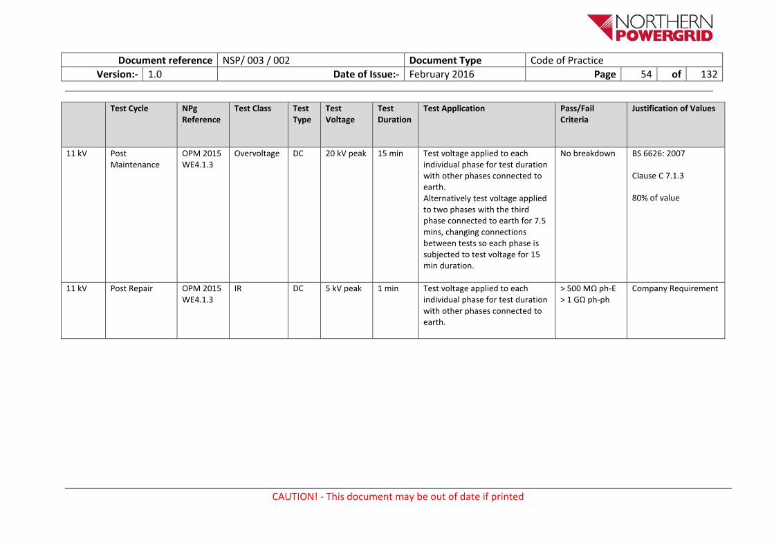
Document reference NSP/ 003 / 002 Document Type Code of Practice
Version:- 1.0 Date of Issue:- February 2016 Page 54 of 132
CAUTION! - This document may be out of date if printed
Test Cycle NPg Reference
Test Class Test Type
Test Voltage
Test Duration
Test Application Pass/Fail Criteria
Justification of Values
11 kV Post Maintenance
OPM 2015 WE4.1.3
Overvoltage DC 20 kV peak 15 min Test voltage applied to each individual phase for test duration with other phases connected to earth. Alternatively test voltage applied to two phases with the third phase connected to earth for 7.5 mins, changing connections between tests so each phase is subjected to test voltage for 15 min duration.
No breakdown BS 6626: 2007
Clause C 7.1.3
80% of value
11 kV Post Repair OPM 2015 WE4.1.3
IR DC 5 kV peak 1 min Test voltage applied to each individual phase for test duration with other phases connected to earth.
> 500 MΩ ph-E > 1 GΩ ph-ph
Company Requirement

Document reference NSP/ 003 / 002 Document Type Code of Practice
Version:- 1.0 Date of Issue:- February 2016 Page 55 of 132
CAUTION! - This document may be out of date if printed
Test Cycle NPg Reference
Test Class Test Type
Test Voltage
Test Duration
Test Application Pass/Fail Criteria
Justification of Values
11 kV Post Repair OPM 2015 WE4.1.3
Overvoltage DC 20 kV peak 15 min Test voltage applied to each individual phase for test duration with other phases connected to earth. Alternatively test voltage applied to two phases with the third phase connected to earth for 7.5 mins, changing connections between tests so each phase is subjected to test voltage for 15 min duration.
No breakdown BS 6626: 2007
Clause C 7.1.3
80% of value

Document reference NSP/ 003 / 002 Document Type Code of Practice
Version:- 1.0 Date of Issue:- February 2016 Page 56 of 132
CAUTION! - This document may be out of date if printed
3.7.2.4. 11 / 20 kV XLPE Cable
Test Cycle NPg Reference
Test Class Test Type
Test Voltage
Test Duration
Test Application Pass/Fail Criteria
Justification of Values
11/20 kV Commissioning OPM 2015 WE4.1.2
IR DC 5 kV peak 1 min Test voltage applied to each individual phase for test duration with other phases connected to earth.
> 500 MΩ ph-E > 1 GΩ ph-ph
Company Requirement
11/20 kV Commissioning OPM 2015 WE4.1.2
Overvoltage DC 28 kV peak 15 min Test voltage applied to each individual phase for test duration with other phases connected to earth. Alternatively test voltage applied to two phases with the third phase connected to earth for 7.5 mins, changing connections between tests so each phase is subjected to test voltage for 15 min duration.
No breakdown Company Requirement
11/20 kV Post Maintenance
OPM 2015 WE4.1.2
IR DC 5 kV peak 1 min Test voltage applied to each individual phase for test duration with other phases connected to earth.
> 500 MΩ ph-E > 1 GΩ ph-ph
Company Requirement

Document reference NSP/ 003 / 002 Document Type Code of Practice
Version:- 1.0 Date of Issue:- February 2016 Page 57 of 132
CAUTION! - This document may be out of date if printed
Test Cycle NPg Reference
Test Class Test Type
Test Voltage
Test Duration
Test Application Pass/Fail Criteria
Justification of Values
11/20 kV Post Maintenance
OPM 2015 WE4.1.2
Overvoltage DC 28 kV peak 15 min Test voltage applied to each individual phase for test duration with other phases connected to earth. Alternatively test voltage applied to two phases with the third phase connected to earth for 7.5 mins, changing connections between tests so each phase is subjected to test voltage for 15 min duration.
No breakdown Company Requirement
11/20 kV Post Repair OPM 2015 WE4.1.2
IR DC 5 kV peak 1 min Test voltage applied to each individual phase for test duration with other phases connected to earth.
> 500 MΩ ph-E > 1 GΩ ph-ph
Company Requirement

Document reference NSP/ 003 / 002 Document Type Code of Practice
Version:- 1.0 Date of Issue:- February 2016 Page 58 of 132
CAUTION! - This document may be out of date if printed
Test Cycle NPg Reference
Test Class Test Type
Test Voltage
Test Duration
Test Application Pass/Fail Criteria
Justification of Values
11/20 kV Post Repair OPM 2015 WE4.1.2
Overvoltage DC 28 kV peak 15 min Test voltage applied to each individual phase for test duration with other phases connected to earth. Alternatively test voltage applied to two phases with the third phase connected to earth for 7.5 mins, changing connections between tests so each phase is subjected to test voltage for 15 min duration.
No breakdown Company Requirement

Document reference NSP/ 003 / 002 Document Type Code of Practice
Version:- 1.0 Date of Issue:- February 2016 Page 59 of 132
CAUTION! - This document may be out of date if printed
3.7.2.5. 20 kV XLPE Cable
Test Cycle NPg Reference
Test Class Test Type
Test Voltage
Test Duration
Test Application Pass/Fail Criteria
Justification of Values
20 kV Commissioning OPM 2015 WE4.1.3
IR DC 5 kV peak 1 min Test voltage applied to each individual phase for test duration with other phases connected to earth.
> 500 MΩ ph-E > 1 GΩ ph-ph
Company Requirement
20 kV Commissioning OPM 2015 WE4.1.3
Overvoltage DC 37 kV peak 15 min Test voltage applied to each individual phase for test duration with other phases connected to earth. Alternatively test voltage applied to two phases with the third phase connected to earth for 7.5 mins, changing connections between tests so each phase is subjected to test voltage for 15 min duration.
No breakdown BS 6626: 2007
Clause C 7.1.3
80% of value
20 kV Post Maintenance
OPM 2015 WE4.1.3
IR DC 5 kV peak 1 min Test voltage applied to each individual phase for test duration with other phases connected to earth.
> 500 MΩ ph-E > 1 GΩ ph-ph
Company Requirement

Document reference NSP/ 003 / 002 Document Type Code of Practice
Version:- 1.0 Date of Issue:- February 2016 Page 60 of 132
CAUTION! - This document may be out of date if printed
Test Cycle NPg Reference
Test Class Test Type
Test Voltage
Test Duration
Test Application Pass/Fail Criteria
Justification of Values
20 kV Post Maintenance
OPM 2015 WE4.1.3
Overvoltage DC 37 kV peak 15 min Test voltage applied to each individual phase for test duration with other phases connected to earth. Alternatively test voltage applied to two phases with the third phase connected to earth for 7.5 mins, changing connections between tests so each phase is subjected to test voltage for 15 min duration.
No breakdown BS 6626: 2007
Clause C 7.1.3
80% of value
20 kV Post Repair OPM 2015 WE4.1.3
IR DC 5 kV peak 1 min Test voltage applied to each individual phase for test duration with other phases connected to earth.
> 500 MΩ ph-E > 1 GΩ ph-ph
Company Requirement

Document reference NSP/ 003 / 002 Document Type Code of Practice
Version:- 1.0 Date of Issue:- February 2016 Page 61 of 132
CAUTION! - This document may be out of date if printed
Test Cycle NPg Reference
Test Class Test Type
Test Voltage
Test Duration
Test Application Pass/Fail Criteria
Justification of Values
20 kV Post Repair OPM 2015 WE4.1.3
Overvoltage DC 37 kV peak 15 min Test voltage applied to each individual phase for test duration with other phases connected to earth. Alternatively test voltage applied to two phases with the third phase connected to earth for 7.5 mins, changing connections between tests so each phase is subjected to test voltage for 15 min duration.
No breakdown BS 6626: 2007
Clause C 7.1.3
80% of value

Document reference NSP/ 003 / 002 Document Type Code of Practice
Version:- 1.0 Date of Issue:- February 2016 Page 62 of 132
CAUTION! - This document may be out of date if printed
3.7.2.6. 25 kV XLPE Cable
Test Cycle NPg Reference
Test Class Test Type
Test Voltage
Test Duration
Test Application Pass/Fail Criteria
Justification of Values
25 kV Commissioning OPM 2015 WE4.1.3
IR DC 5 kV peak 1 min Test voltage applied to each individual phase for test duration with other phases connected to earth.
> 500 MΩ ph-E > 1 GΩ ph-ph
Company Requirement
25 kV Commissioning OPM 2015 WE4.1.3
Overvoltage DC 37 kV peak 15 min Test voltage applied to each individual phase for test duration with other phases connected to earth. Alternatively test voltage applied to two phases with the third phase connected to earth for 7.5 mins, changing connections between tests so each phase is subjected to test voltage for 15 min duration.
No breakdown BS 6626: 2007
Clause C 7.1.3
Reduced value
25 kV Post Maintenance
OPM 2015 WE4.1.3
IR DC 5 kV peak 1 min Test voltage applied to each individual phase for test duration with other phases connected to earth.
> 500 MΩ ph-E > 1 GΩ ph-ph
Company Requirement

Document reference NSP/ 003 / 002 Document Type Code of Practice
Version:- 1.0 Date of Issue:- February 2016 Page 63 of 132
CAUTION! - This document may be out of date if printed
Test Cycle NPg Reference
Test Class Test Type
Test Voltage
Test Duration
Test Application Pass/Fail Criteria
Justification of Values
25 kV Post Maintenance
OPM 2015 WE4.1.3
Overvoltage DC 37 kV peak 15 min Test voltage applied to each individual phase for test duration with other phases connected to earth. Alternatively test voltage applied to two phases with the third phase connected to earth for 7.5 mins, changing connections between tests so each phase is subjected to test voltage for 15 min duration.
No breakdown BS 6626: 2007
Clause C 7.1.3
Reduced value
25 kV Post Repair OPM 2015 WE4.1.3
IR DC 5 kV peak 1 min Test voltage applied to each individual phase for test duration with other phases connected to earth.
> 500 MΩ ph-E > 1 GΩ ph-ph
Company Requirement
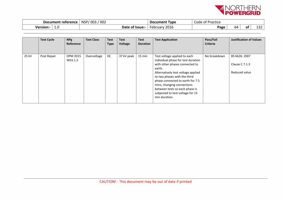
Document reference NSP/ 003 / 002 Document Type Code of Practice
Version:- 1.0 Date of Issue:- February 2016 Page 64 of 132
CAUTION! - This document may be out of date if printed
Test Cycle NPg Reference
Test Class Test Type
Test Voltage
Test Duration
Test Application Pass/Fail Criteria
Justification of Values
25 kV Post Repair OPM 2015 WE4.1.3
Overvoltage DC 37 kV peak 15 min Test voltage applied to each individual phase for test duration with other phases connected to earth. Alternatively test voltage applied to two phases with the third phase connected to earth for 7.5 mins, changing connections between tests so each phase is subjected to test voltage for 15 min duration.
No breakdown BS 6626: 2007
Clause C 7.1.3
Reduced value

Document reference NSP/ 003 / 002 Document Type Code of Practice
Version:- 1.0 Date of Issue:- February 2016 Page 65 of 132
CAUTION! - This document may be out of date if printed
3.7.2.7. 33 kV XLPE Cable
System Voltage
Test Cycle NPg Reference
Test Class Test Type
Test Voltage
Test Duration
Test Application Pass/Fail Criteria
Justification of Values
33 kV Commissioning OPM 2015 WE4.1
IR DC 5 kV peak 1 min Test voltage applied to each individual phase for test duration with other phases connected to earth.
> 500 MΩ ph-E > 1 GΩ ph-ph
Company Requirement
33 kV Commissioning OPM 2015 WE4.1
Overvoltage DC 50 kV peak 15 min Test voltage applied to each individual phase for test duration with other phases connected to earth. Alternatively test voltage applied to two phases with the third phase connected to earth for 7.5 mins, changing connections between tests so each phase is subjected to test voltage for 15 min duration.
No breakdown BS 6626: 2007
Clause C 7.1.3
Reduced value
33 kV Commissioning OPM 2015 WE4.1
Overvoltage VLF 36 kV rms 60 min Test voltage applied to each individual phase for test duration with other phases connected to earth.
No breakdown IEEE 400.2
Reduced value
33 kV Commissioning OPM 2015 WE4.1
Overvoltage VLF 50 kV peak 60 min Test voltage applied to each individual phase for test duration with other phases connected to earth.
No breakdown IEEE 400.2
Reduced value

Document reference NSP/ 003 / 002 Document Type Code of Practice
Version:- 1.0 Date of Issue:- February 2016 Page 66 of 132
CAUTION! - This document may be out of date if printed
System Voltage
Test Cycle NPg Reference
Test Class Test Type
Test Voltage
Test Duration
Test Application Pass/Fail Criteria
Justification of Values
33 kV Post Maintenance
OPM 2015 WE4.1
IR DC 5 kV peak 1 min Test voltage applied to each individual phase for test duration with other phases connected to earth.
> 500 MΩ ph-E > 1 GΩ ph-ph
Company Requirement
33 kV Post Maintenance
OPM 2015 WE4.1
Overvoltage DC 50 kV peak 15 min Test voltage applied to each individual phase for test duration with other phases connected to earth. Alternatively test voltage applied to two phases with the third phase connected to earth for 7.5 mins, changing connections between tests so each phase is subjected to test voltage for 15 min duration.
No breakdown BS 6626: 2007
Clause C 7.1.3
Reduced value
33 kV Post Maintenance
OPM 2015 WE4.1
Overvoltage VLF 36 kV rms 60 min Test voltage applied to each individual phase for test duration with other phases connected to earth.
No breakdown IEEE 400.2
Reduced value
33 kV Post Maintenance
OPM 2015 WE4.1
Overvoltage VLF 50 kV peak 60 min Test voltage applied to each individual phase for test duration with other phases connected to earth.
No breakdown IEEE 400.2
Reduced value

Document reference NSP/ 003 / 002 Document Type Code of Practice
Version:- 1.0 Date of Issue:- February 2016 Page 67 of 132
CAUTION! - This document may be out of date if printed
System Voltage
Test Cycle NPg Reference
Test Class Test Type
Test Voltage
Test Duration
Test Application Pass/Fail Criteria
Justification of Values
33 kV Post Repair OPM 2015 WE4.1
IR DC 5 kV peak 1 min Test voltage applied to each individual phase for test duration with other phases connected to earth.
> 500 MΩ ph-E > 1 GΩ ph-ph
Company Requirement
33 kV Post Repair OPM 2015 WE4.1
Overvoltage DC 50 kV peak 15 min Test voltage applied to each individual phase for test duration with other phases connected to earth. Alternatively test voltage applied to two phases with the third phase connected to earth for 7.5 mins, changing connections between tests so each phase is subjected to test voltage for 15 min duration.
No breakdown BS 6626: 2007
Clause C 7.1.3
Reduced value
33 kV Post Repair OPM 2015 WE4.1
Overvoltage VLF 36 kV rms 60 min Test voltage applied to each individual phase for test duration with other phases connected to earth.
No breakdown IEEE 400.2
Reduced value
33 kV Post Repair OPM 2015 WE4.1
Overvoltage VLF 50 kV peak 60 min Test voltage applied to each individual phase for test duration with other phases connected to earth.
No breakdown IEEE 400.2
Reduced value

Document reference NSP/ 003 / 002 Document Type Code of Practice
Version:- 1.0 Date of Issue:- February 2016 Page 68 of 132
CAUTION! - This document may be out of date if printed
3.7.2.8. 66 kV XLPE Cable
System Voltage
Test Cycle NPg Reference
Test Class Test Type
Test Voltage
Test Duration
Test Application Pass/Fail Criteria
Justification of Values
66 kV Commissioning OPM 2015 WE4.1
IR DC 5 kV peak 1 min Test voltage applied to each individual phase for test duration with other phases connected to earth.
> 500 MΩ ph-E > 1 GΩ ph-ph
Company Requirement
66 kV Commissioning OPM 2015 WE4.1
Overvoltage VLF 66 kV rms 60 min Test voltage applied to each individual phase for test duration with other phases connected to earth.
No breakdown IEEE 400.2
Reduced value
66 kV Commissioning OPM 2015 WE4.1
Overvoltage VLF 94 kV peak 60 min Test voltage applied to each individual phase for test duration with other phases connected to earth.
No breakdown IEEE 400.2
Reduced value
66 kV Commissioning OPM 2015 WE4.1
Overvoltage AC PF 72 kV rms 60 min Test voltage applied to each individual phase for test duration with other phases connected to earth.
No breakdown BS 7912: 2012
Clause 18.1.2
Table 11
66 kV Post Maintenance
OPM 2015 WE4.1
IR DC 5 kV peak 1 min Test voltage applied to each individual phase for test duration with other phases connected to earth.
> 500 MΩ ph-E > 1 GΩ ph-ph
Company Requirement

Document reference NSP/ 003 / 002 Document Type Code of Practice
Version:- 1.0 Date of Issue:- February 2016 Page 69 of 132
CAUTION! - This document may be out of date if printed
System Voltage
Test Cycle NPg Reference
Test Class Test Type
Test Voltage
Test Duration
Test Application Pass/Fail Criteria
Justification of Values
66 kV Post Maintenance
OPM 2015 WE4.1
Overvoltage VLF 66 kV rms 60 min Test voltage applied to each individual phase for test duration with other phases connected to earth.
No breakdown IEEE 400.2
Reduced value
66 kV Post Maintenance
OPM 2015 WE4.1
Overvoltage VLF 94 kV peak 60 min Test voltage applied to each individual phase for test duration with other phases connected to earth.
No breakdown IEEE 400.2
Reduced value
66 kV Post Maintenance
OPM 2015 WE4.1
Overvoltage AC PF 72 kV rms 60 min Test voltage applied to each individual phase for test duration with other phases connected to earth.
No breakdown BS 7912: 2012
Clause 18.1.2
Table 11
66 kV Post Repair OPM 2015 WE4.1
IR DC 5 kV peak 1 min Test voltage applied to each individual phase for test duration with other phases connected to earth.
> 500 MΩ ph-E > 1 GΩ ph-ph
Company Requirement
66 kV Post Repair OPM 2015 WE4.1
Overvoltage VLF 66 kV rms 60 min Test voltage applied to each individual phase for test duration with other phases connected to earth.
No breakdown IEEE 400.2
Reduced value

Document reference NSP/ 003 / 002 Document Type Code of Practice
Version:- 1.0 Date of Issue:- February 2016 Page 70 of 132
CAUTION! - This document may be out of date if printed
System Voltage
Test Cycle NPg Reference
Test Class Test Type
Test Voltage
Test Duration
Test Application Pass/Fail Criteria
Justification of Values
66 kV Post Repair OPM 2015 WE4.1
Overvoltage VLF 94 kV peak 60 min Test voltage applied to each individual phase for test duration with other phases connected to earth.
No breakdown IEEE 400.2
Reduced value
66 kV Post Repair OPM 2015 WE4.1
Overvoltage AC PF 72 kV rms 60 min Test voltage applied to each individual phase for test duration with other phases connected to earth.
No breakdown BS 7912: 2012
Clause 18.1.2
Table 11

Document reference NSP/ 003 / 002 Document Type Code of Practice
Version:- 1.0 Date of Issue:- February 2016 Page 71 of 132
CAUTION! - This document may be out of date if printed
3.7.2.9. 132 kV XLPE Cable
System Voltage
Test Cycle NPg Reference
Test Class Test Type
Test Voltage
Test Duration
Test Application Pass/Fail Criteria
Justification of Values
132 kV Commissioning OPM 2015 WE4.1
IR DC 5 kV peak 1 min Test voltage applied to each individual phase for test duration with other phases connected to earth.
> 500 MΩ ph-E > 1 GΩ ph-ph
Company Requirement
132 kV Commissioning OPM 2015 WE4.1
Overvoltage VLF 141 kV rms 60 min Test voltage applied to each individual phase for test duration with other phases connected to earth.
No breakdown IEEE 400.2
Reduced value
132 kV Commissioning OPM 2015 WE4.1
Overvoltage VLF 200 kV peak
60 min Test voltage applied to each individual phase for test duration with other phases connected to earth.
No breakdown IEEE 400.2
Reduced value
132 kV Commissioning OPM 2015 WE4.1
Overvoltage AC PF 132 kV rms 60 min Test voltage applied to each individual phase for test duration with other phases connected to earth.
No breakdown BS 7912: 2012
Clause 18.1.2
Table 11
132 kV Post Maintenance
OPM 2015 WE4.1
IR DC 5 kV peak 1 min Test voltage applied to each individual phase for test duration with other phases connected to earth.
> 500 MΩ ph-E > 1 GΩ ph-ph
Company Requirement

Document reference NSP/ 003 / 002 Document Type Code of Practice
Version:- 1.0 Date of Issue:- February 2016 Page 72 of 132
CAUTION! - This document may be out of date if printed
System Voltage
Test Cycle NPg Reference
Test Class Test Type
Test Voltage
Test Duration
Test Application Pass/Fail Criteria
Justification of Values
132 kV Post Maintenance
OPM 2015 WE4.1
Overvoltage VLF 141 kV rms 60 min Test voltage applied to each individual phase for test duration with other phases connected to earth.
No breakdown IEEE 400.2
Reduced value
132 kV Post Maintenance
OPM 2015 WE4.1
Overvoltage VLF 200 kV peak
60 min Test voltage applied to each individual phase for test duration with other phases connected to earth.
No breakdown IEEE 400.2
Reduced value
132 kV Post Maintenance
OPM 2015 WE4.1
Overvoltage AC PF 132 kV rms 60 min Test voltage applied to each individual phase for test duration with other phases connected to earth.
No breakdown BS 7912: 2012
Clause 18.1.2
Table 11
132 kV Post Repair OPM 2015 WE4.1
IR DC 5 kV peak 1 min Test voltage applied to each individual phase for test duration with other phases connected to earth.
> 500 MΩ ph-E > 1 GΩ ph-ph
Company Requirement
132 kV Post Repair OPM 2015 WE4.1
Overvoltage VLF 141 kV rms 60 min Test voltage applied to each individual phase for test duration with other phases connected to earth.
No breakdown IEEE 400.2
Reduced value

Document reference NSP/ 003 / 002 Document Type Code of Practice
Version:- 1.0 Date of Issue:- February 2016 Page 73 of 132
CAUTION! - This document may be out of date if printed
System Voltage
Test Cycle NPg Reference
Test Class Test Type
Test Voltage
Test Duration
Test Application Pass/Fail Criteria
Justification of Values
132 kV Post Repair OPM 2015 WE4.1
Overvoltage VLF 200 kV peak
60 min Test voltage applied to each individual phase for test duration with other phases connected to earth.
No breakdown IEEE 400.2
Reduced value
132 kV Post Repair OPM 2015 WE4.1
Overvoltage AC PF 132 kV rms 60 min Test voltage applied to each individual phase for test duration with other phases connected to earth.
No breakdown BS 7912: 2012
Clause 18.1.2
Table 11

Document reference NSP/ 003 / 002 Document Type Code of Practice
Version:- 1.0 Date of Issue:- February 2016 Page 74 of 132
CAUTION! - This document may be out of date if printed
3.8. Switchgear
3.8.1. Isolatable
3.8.1.1. 3.3 kV Isolatable Switchgear
System Voltage
Test Cycle NPg Reference
Test Class Test Type
Test Voltage
Test Duration
Test Application Pass/Fail Criteria
Justification of Values
3.3 kV Commissioning OPS 2015 WE4.2
IR DC 5 kV peak 1 min Test voltage applied between each phase and earth, between phases and across open contacts.
> 2 GΩ ph-E > 4 GΩ ph-ph or > 1 GΩ all in
BS 6626: 2010
Clause 24.2
Table 1
3.3 kV Commissioning OPS 2015 WE4.2
Overvoltage DC 6 kV peak 1 min Test voltage applied between each phase and earth, between phases and across open contacts.
No breakdown Company Requirement
3.3 kV Commissioning OPS 2015 WE4.2
Overvoltage AC PF 5 kV rms 1 min Test voltage applied between each phase and earth, between phases and across open contacts.
No breakdown BS EN 62271-1: 2008
Clause 6.2.11
3.3 kV Post Maintenance
OPS 2015 WE4.2
IR DC 5 kV peak 1 min Test voltage applied between each phase and earth, between phases and across open contacts.
> 2 GΩ ph-E > 4 GΩ ph-ph or > 1 GΩ all in
BS 6626: 2010
Clause 24.2
Table 1

Document reference NSP/ 003 / 002 Document Type Code of Practice
Version:- 1.0 Date of Issue:- February 2016 Page 75 of 132
CAUTION! - This document may be out of date if printed
System Voltage
Test Cycle NPg Reference
Test Class Test Type
Test Voltage
Test Duration
Test Application Pass/Fail Criteria
Justification of Values
3.3 kV Post Maintenance
OPS 2015 WE4.2
Overvoltage DC 6 kV peak 1 min Test voltage applied between each phase and earth, between phases and across open contacts.
No breakdown Company Requirement
3.3 kV Post Maintenance
OPS 2015 WE4.2
Overvoltage AC PF 5 kV rms 1 min Test voltage applied between each phase and earth, between phases and across open contacts.
No breakdown BS EN 62271-1: 2008
Clause 6.2.11
3.3 kV Post Repair OPS 2015 WE4.2
IR DC 5 kV peak 1 min Test voltage applied between each phase and earth, between phases and across open contacts.
> 2 GΩ ph-E > 4 GΩ ph-ph or > 1 GΩ all in
BS 6626: 2010
Clause 24.2
Table 1
3.3 kV Post Repair OPS 2015 WE4.2
Overvoltage DC 6 kV peak 1 min Test voltage applied between each phase and earth, between phases and across open contacts.
No breakdown Company Requirement
3.3 kV Post Repair OPS 2015 WE4.2
Overvoltage AC PF 5 kV rms 1 min Test voltage applied between each phase and earth, between phases and across open contacts.
No breakdown BS EN 62271-1: 2008
Clause 6.2.11

Document reference NSP/ 003 / 002 Document Type Code of Practice
Version:- 1.0 Date of Issue:- February 2016 Page 76 of 132
CAUTION! - This document may be out of date if printed
3.8.1.3. 6.6 kV Isolatable Switchgear
System Voltage
Test Cycle NPg Reference
Test Class Test Type
Test Voltage
Test Duration
Test Application Pass/Fail Criteria
Justification of Values
6.6 kV Commissioning OPS 2015 WE4.2
IR DC 5 kV peak 1 min Test voltage applied between each phase and earth, between phases and across open contacts.
> 2 GΩ ph-E > 4 GΩ ph-ph or > 1 GΩ all in
BS 6626: 2010
Clause 24.2
Table 1
6.6 kV Commissioning OPS 2015 WE4.2
Overvoltage DC 12 kV peak 1 min Test voltage applied between each phase and earth, between phases and across open contacts.
No breakdown Company Requirement
6.6 kV Commissioning OPS 2015 WE4.2
Overvoltage AC PF 10 kV rms 1 min Test voltage applied between each phase and earth, between phases and across open contacts.
No breakdown BS EN 62271-1: 2008
Clause 6.2.11
6.6 kV Post Maintenance
OPS 2015 WE4.2
IR DC 5 kV peak 1 min Test voltage applied between each phase and earth, between phases and across open contacts.
> 2 GΩ ph-E > 4 GΩ ph-ph or > 1 GΩ all in
BS 6626: 2010
Clause 24.2
Table 1
6.6 kV Post Maintenance
OPS 2015 WE4.2
Overvoltage DC 12 kV peak 1 min Test voltage applied between each phase and earth, between phases and across open contacts.
No breakdown Company Requirement

Document reference NSP/ 003 / 002 Document Type Code of Practice
Version:- 1.0 Date of Issue:- February 2016 Page 77 of 132
CAUTION! - This document may be out of date if printed
System Voltage
Test Cycle NPg Reference
Test Class Test Type
Test Voltage
Test Duration
Test Application Pass/Fail Criteria
Justification of Values
6.6 kV Post Maintenance
OPS 2015 WE4.2
Overvoltage AC PF 10 kV rms 1 min Test voltage applied between each phase and earth, between phases and across open contacts.
No breakdown BS EN 62271-1: 2008
Clause 6.2.11
6.6 kV Post Repair OPS 2015 WE4.2
IR DC 5 kV peak 1 min Test voltage applied between each phase and earth, between phases and across open contacts.
> 2 GΩ ph-E > 4 GΩ ph-ph or > 1 GΩ all in
BS 6626: 2010
Clause 24.2
Table 1
6.6 kV Post Repair OPS 2015 WE4.2
Overvoltage DC 12 kV peak 1 min Test voltage applied between each phase and earth, between phases and across open contacts.
No breakdown Company Requirement
6.6 kV Post Repair OPS 2015 WE4.2
Overvoltage AC PF 10 kV rms 1 min Test voltage applied between each phase and earth, between phases and across open contacts.
No breakdown BS EN 62271-1: 2008
Clause 6.2.11
3.8.1.4. 11 kV Isolatable Switchgear
System Voltage
Test Cycle NPg Reference
Test Class Test Type
Test Voltage
Test Duration
Test Application Pass/Fail Criteria
Justification of Values

Document reference NSP/ 003 / 002 Document Type Code of Practice
Version:- 1.0 Date of Issue:- February 2016 Page 78 of 132
CAUTION! - This document may be out of date if printed
System Voltage
Test Cycle NPg Reference
Test Class Test Type
Test Voltage
Test Duration
Test Application Pass/Fail Criteria
Justification of Values
11 kV Commissioning OPS 2015 WE4.2
IR DC 5 kV peak 1 min Test voltage applied between each phase and earth, between phases and across open contacts.
> 2 GΩ ph-E > 4 GΩ ph-ph or > 1 GΩ all in
BS 6626: 2010
Clause 24.2
Table 1
11 kV Commissioning OPS 2015 WE4.2
Overvoltage DC 20 kV peak 1 min Test voltage applied between each phase and earth, between phases and across open contacts.
No breakdown Company Requirement
11 kV Commissioning OPS 2015 WE4.2
Overvoltage AC PF 16 kV rms 1 min Test voltage applied between each phase and earth, between phases and across open contacts.
No breakdown BS EN 62271-1: 2008
Clause 6.2.11
11 kV Post Maintenance
OPS 2015 WE4.2
IR DC 5 kV peak 1 min Test voltage applied between each phase and earth, between phases and across open contacts.
> 2 GΩ ph-E > 4 GΩ ph-ph or > 1 GΩ all in
BS 6626: 2010
Clause 24.2
Table 1
11 kV Post Maintenance
OPS 2015 WE4.2
Overvoltage DC 20 kV peak 1 min Test voltage applied between each phase and earth, between phases and across open contacts.
No breakdown Company Requirement
11 kV Post Maintenance
OPS 2015 WE4.2
Overvoltage AC PF 16 kV rms 1 min Test voltage applied between each phase and earth, between phases and across open contacts.
No breakdown BS EN 62271-1: 2008
Clause 6.2.11

Document reference NSP/ 003 / 002 Document Type Code of Practice
Version:- 1.0 Date of Issue:- February 2016 Page 79 of 132
CAUTION! - This document may be out of date if printed
System Voltage
Test Cycle NPg Reference
Test Class Test Type
Test Voltage
Test Duration
Test Application Pass/Fail Criteria
Justification of Values
11 kV Post Repair OPS 2015 WE4.2
IR DC 5 kV peak 1 min Test voltage applied between each phase and earth, between phases and across open contacts.
> 2 GΩ ph-E > 4 GΩ ph-ph or > 1 GΩ all in
BS 6626: 2010
Clause 24.2
Table 1
11 kV Post Repair OPS 2015 WE4.2
Overvoltage DC 20 kV peak 1 min Test voltage applied between each phase and earth, between phases and across open contacts.
No breakdown Company Requirement
11 kV Post Repair OPS 2015 WE4.2
Overvoltage AC PF 16 kV rms 1 min Test voltage applied between each phase and earth, between phases and across open contacts.
No breakdown BS EN 62271-1: 2008
Clause 6.2.11

Document reference NSP/ 003 / 002 Document Type Code of Practice
Version:- 1.0 Date of Issue:- February 2016 Page 80 of 132
CAUTION! - This document may be out of date if printed
3.8.1.5. 20 kV Isolatable Switchgear
System Voltage
Test Cycle NPg Reference
Test Class Test Type
Test Voltage
Test Duration
Test Application Pass/Fail Criteria
Justification of Values
20 kV Commissioning OPS 2015 WE4.2
IR DC 5 kV peak 1 min Test voltage applied between each phase and earth, between phases and across open contacts.
> 2 GΩ ph-E > 4 GΩ ph-ph or > 1 GΩ all in
BS 6626: 2010
Clause 24.2
Table 1
20 kV Commissioning OPS 2015 WE4.2
Overvoltage DC 37 kV peak 1 min Test voltage applied between each phase and earth, between phases and across open contacts.
No breakdown Company Requirement
20 kV Commissioning OPS 2015 WE4.2
Overvoltage AC PF 30 kV rms 1 min Test voltage applied between each phase and earth, between phases and across open contacts.
No breakdown BS EN 62271-1: 2008
Clause 6.2.11
20 kV Post Maintenance
OPS 2015 WE4.2
IR DC 5 kV peak 1 min Test voltage applied between each phase and earth, between phases and across open contacts.
> 2 GΩ ph-E > 4 GΩ ph-ph or > 1 GΩ all in
BS 6626: 2010
Clause 24.2
Table 1
20 kV Post Maintenance
OPS 2015 WE4.2
Overvoltage DC 37 kV peak 1 min Test voltage applied between each phase and earth, between phases and across open contacts.
No breakdown Company Requirement
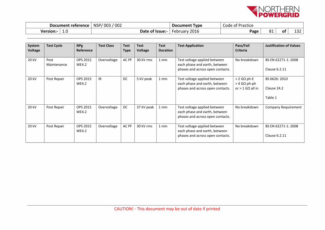
Document reference NSP/ 003 / 002 Document Type Code of Practice
Version:- 1.0 Date of Issue:- February 2016 Page 81 of 132
CAUTION! - This document may be out of date if printed
System Voltage
Test Cycle NPg Reference
Test Class Test Type
Test Voltage
Test Duration
Test Application Pass/Fail Criteria
Justification of Values
20 kV Post Maintenance
OPS 2015 WE4.2
Overvoltage AC PF 30 kV rms 1 min Test voltage applied between each phase and earth, between phases and across open contacts.
No breakdown BS EN 62271-1: 2008
Clause 6.2.11
20 kV Post Repair OPS 2015 WE4.2
IR DC 5 kV peak 1 min Test voltage applied between each phase and earth, between phases and across open contacts.
> 2 GΩ ph-E > 4 GΩ ph-ph or > 1 GΩ all in
BS 6626: 2010
Clause 24.2
Table 1
20 kV Post Repair OPS 2015 WE4.2
Overvoltage DC 37 kV peak 1 min Test voltage applied between each phase and earth, between phases and across open contacts.
No breakdown Company Requirement
20 kV Post Repair OPS 2015 WE4.2
Overvoltage AC PF 30 kV rms 1 min Test voltage applied between each phase and earth, between phases and across open contacts.
No breakdown BS EN 62271-1: 2008
Clause 6.2.11
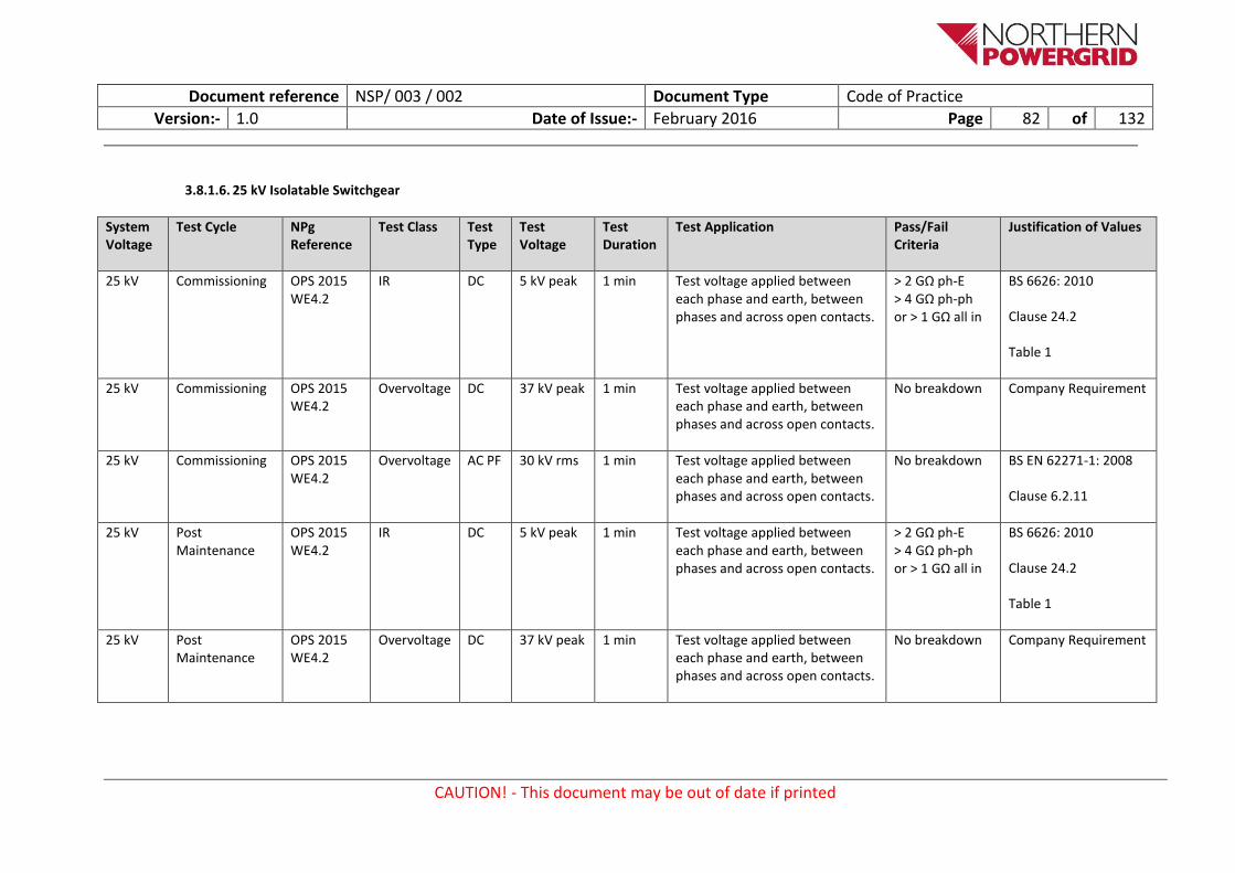
Document reference NSP/ 003 / 002 Document Type Code of Practice
Version:- 1.0 Date of Issue:- February 2016 Page 82 of 132
CAUTION! - This document may be out of date if printed
3.8.1.6. 25 kV Isolatable Switchgear
System Voltage
Test Cycle NPg Reference
Test Class Test Type
Test Voltage
Test Duration
Test Application Pass/Fail Criteria
Justification of Values
25 kV Commissioning OPS 2015 WE4.2
IR DC 5 kV peak 1 min Test voltage applied between each phase and earth, between phases and across open contacts.
> 2 GΩ ph-E > 4 GΩ ph-ph or > 1 GΩ all in
BS 6626: 2010
Clause 24.2
Table 1
25 kV Commissioning OPS 2015 WE4.2
Overvoltage DC 37 kV peak 1 min Test voltage applied between each phase and earth, between phases and across open contacts.
No breakdown Company Requirement
25 kV Commissioning OPS 2015 WE4.2
Overvoltage AC PF 30 kV rms 1 min Test voltage applied between each phase and earth, between phases and across open contacts.
No breakdown BS EN 62271-1: 2008
Clause 6.2.11
25 kV Post Maintenance
OPS 2015 WE4.2
IR DC 5 kV peak 1 min Test voltage applied between each phase and earth, between phases and across open contacts.
> 2 GΩ ph-E > 4 GΩ ph-ph or > 1 GΩ all in
BS 6626: 2010
Clause 24.2
Table 1
25 kV Post Maintenance
OPS 2015 WE4.2
Overvoltage DC 37 kV peak 1 min Test voltage applied between each phase and earth, between phases and across open contacts.
No breakdown Company Requirement

Document reference NSP/ 003 / 002 Document Type Code of Practice
Version:- 1.0 Date of Issue:- February 2016 Page 83 of 132
CAUTION! - This document may be out of date if printed
System Voltage
Test Cycle NPg Reference
Test Class Test Type
Test Voltage
Test Duration
Test Application Pass/Fail Criteria
Justification of Values
25 kV Post Maintenance
OPS 2015 WE4.2
Overvoltage AC PF 30 kV rms 1 min Test voltage applied between each phase and earth, between phases and across open contacts.
No breakdown BS EN 62271-1: 2008
Clause 6.2.11
25 kV Post Repair OPS 2015 WE4.2
IR DC 5 kV peak 1 min Test voltage applied between each phase and earth, between phases and across open contacts.
> 2 GΩ ph-E > 4 GΩ ph-ph or > 1 GΩ all in
BS 6626: 2010
Clause 24.2
Table 1
25 kV Post Repair OPS 2015 WE4.2
Overvoltage DC 37 kV peak 1 min Test voltage applied between each phase and earth, between phases and across open contacts.
No breakdown Company Requirement
25 kV Post Repair OPS 2015 WE4.2
Overvoltage AC PF 30 kV rms 1 min Test voltage applied between each phase and earth, between phases and across open contacts.
No breakdown BS EN 62271-1: 2008
Clause 6.2.11

Document reference NSP/ 003 / 002 Document Type Code of Practice
Version:- 1.0 Date of Issue:- February 2016 Page 84 of 132
CAUTION! - This document may be out of date if printed
3.8.1.7. 33 kV Isolatable Switchgear
System Voltage
Test Cycle NPg Reference
Test Class Test Type
Test Voltage
Test Duration
Test Application Pass/Fail Criteria Justification of Values
33 kV Commissioning OPS 2015 WE4.2
IR DC 5 kV peak 1 min Test voltage applied between each phase and earth, between phases and across open contacts.
> 2 GΩ ph-E > 4 GΩ ph-ph or > 1 GΩ all in
BS 6626: 2010
Clause 24.2
Table 1
33 kV Commissioning OPS 2015 WE4.2
Overvoltage DC 50 kV peak 1 min Test voltage applied between each phase and earth, between phases and across open contacts.
No breakdown Company Requirement
33 kV Commissioning OPS 2015 WE4.2
Overvoltage AC PF 50 kV rms 1 min Test voltage applied between each phase and earth, between phases and across open contacts.
No breakdown BS EN 62271-1: 2008
Clause 6.2.11
33 kV Post Maintenance
OPS 2015 WE4.2
IR DC 5 kV peak 1 min Test voltage applied between each phase and earth, between phases and across open contacts.
> 2 GΩ ph-E > 4 GΩ ph-ph or > 1 GΩ all in
BS 6626: 2010
Clause 24.2
Table 1
33 kV Post Maintenance
OPS 2015 WE4.2
Overvoltage DC 50 kV peak 1 min Test voltage applied between each phase and earth, between phases and across open contacts.
No breakdown Company Requirement

Document reference NSP/ 003 / 002 Document Type Code of Practice
Version:- 1.0 Date of Issue:- February 2016 Page 85 of 132
CAUTION! - This document may be out of date if printed
System Voltage
Test Cycle NPg Reference
Test Class Test Type
Test Voltage
Test Duration
Test Application Pass/Fail Criteria Justification of Values
33 kV Post Maintenance
OPS 2015 WE4.2
Overvoltage AC PF 50 kV rms 1 min Test voltage applied between each phase and earth, between phases and across open contacts.
No breakdown BS EN 62271-1: 2008
Clause 6.2.11
33 kV Post Repair OPS 2015 WE4.2
IR DC 5 kV peak 1 min Test voltage applied between each phase and earth, between phases and across open contacts.
> 2 GΩ ph-E > 4 GΩ ph-ph or > 1 GΩ all in
BS 6626: 2010
Clause 24.2
Table 1
33 kV Post Repair OPS 2015 WE4.2
Overvoltage DC 50 kV peak 1 min Test voltage applied between each phase and earth, between phases and across open contacts.
No breakdown Company Requirement
33 kV Post Repair OPS 2015 WE4.2
Overvoltage AC PF 50 kV rms 1 min Test voltage applied between each phase and earth, between phases and across open contacts.
No breakdown BS EN 62271-1: 2008
Clause 6.2.11

Document reference NSP/ 003 / 002 Document Type Code of Practice
Version:- 1.0 Date of Issue:- February 2016 Page 86 of 132
CAUTION! - This document may be out of date if printed
3.8.1.8. 66 kV Isolatable Switchgear
System Voltage
Test Cycle NPg Reference
Test Class Test Type
Test Voltage
Test Duration
Test Application Pass/Fail Criteria Justification of Values
66 kV Commissioning OPS 2015 WE4.2
IR DC 5 kV peak 1 min Test voltage applied between each phase and earth, between phases and across open contacts.
> 2 GΩ ph-E > 4 GΩ ph-ph or > 1 GΩ all in
BS 6626: 2010
Clause 24.2
Table 1
66 kV Commissioning OPS 2015 WE4.2
Overvoltage DC 100 kV peak
1 min Test voltage applied between each phase and earth, between phases and across open contacts.
No breakdown Company Requirement
66 kV Commissioning OPS 2015 WE4.2
Overvoltage AC PF 85 kV rms 1 min Test voltage applied between each phase and earth, between phases and across open contacts.
No breakdown BS EN 62271-1: 2008
Clause 6.2.11
66 kV Post Maintenance
OPS 2015 WE4.2
IR DC 5 kV peak 1 min Test voltage applied between each phase and earth, between phases and across open contacts.
> 2 GΩ ph-E > 4 GΩ ph-ph or > 1 GΩ all in
BS 6626: 2010
Clause 24.2
Table 1
66 kV Post Maintenance
OPS 2015 WE4.2
Overvoltage DC 100 kV peak
1 min Test voltage applied between each phase and earth, between phases and across open contacts.
No breakdown Company Requirement

Document reference NSP/ 003 / 002 Document Type Code of Practice
Version:- 1.0 Date of Issue:- February 2016 Page 87 of 132
CAUTION! - This document may be out of date if printed
System Voltage
Test Cycle NPg Reference
Test Class Test Type
Test Voltage
Test Duration
Test Application Pass/Fail Criteria Justification of Values
66 kV Post Maintenance
OPS 2015 WE4.2
Overvoltage AC PF 85 kV rms 1 min Test voltage applied between each phase and earth, between phases and across open contacts.
No breakdown BS EN 62271-1: 2008
Clause 6.2.11
66 kV Post Repair OPS 2015 WE4.2
IR DC 5 kV peak 1 min Test voltage applied between each phase and earth, between phases and across open contacts.
> 2 GΩ ph-E > 4 GΩ ph-ph or > 1 GΩ all in
BS 6626: 2010
Clause 24.2
Table 1
66 kV Post Repair OPS 2015 WE4.2
Overvoltage DC 100 kV peak
1 min Test voltage applied between each phase and earth, between phases and across open contacts.
No breakdown Company Requirement
66 kV Post Repair OPS 2015 WE4.2
Overvoltage AC PF 85 kV rms 1 min Test voltage applied between each phase and earth, between phases and across open contacts.
No breakdown BS EN 62271-1: 2008
Clause 6.2.11
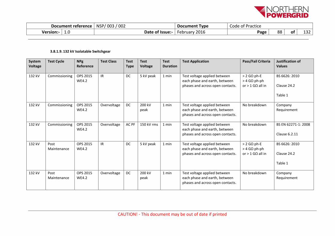
Document reference NSP/ 003 / 002 Document Type Code of Practice
Version:- 1.0 Date of Issue:- February 2016 Page 88 of 132
CAUTION! - This document may be out of date if printed
3.8.1.9. 132 kV Isolatable Switchgear
System Voltage
Test Cycle NPg Reference
Test Class Test Type
Test Voltage
Test Duration
Test Application Pass/Fail Criteria Justification of Values
132 kV Commissioning OPS 2015 WE4.2
IR DC 5 kV peak 1 min Test voltage applied between each phase and earth, between phases and across open contacts.
> 2 GΩ ph-E > 4 GΩ ph-ph or > 1 GΩ all in
BS 6626: 2010
Clause 24.2
Table 1
132 kV Commissioning OPS 2015 WE4.2
Overvoltage DC 200 kV peak
1 min Test voltage applied between each phase and earth, between phases and across open contacts.
No breakdown Company Requirement
132 kV Commissioning OPS 2015 WE4.2
Overvoltage AC PF 150 kV rms 1 min Test voltage applied between each phase and earth, between phases and across open contacts.
No breakdown BS EN 62271-1: 2008
Clause 6.2.11
132 kV Post Maintenance
OPS 2015 WE4.2
IR DC 5 kV peak 1 min Test voltage applied between each phase and earth, between phases and across open contacts.
> 2 GΩ ph-E > 4 GΩ ph-ph or > 1 GΩ all in
BS 6626: 2010
Clause 24.2
Table 1
132 kV Post Maintenance
OPS 2015 WE4.2
Overvoltage DC 200 kV peak
1 min Test voltage applied between each phase and earth, between phases and across open contacts.
No breakdown Company Requirement

Document reference NSP/ 003 / 002 Document Type Code of Practice
Version:- 1.0 Date of Issue:- February 2016 Page 89 of 132
CAUTION! - This document may be out of date if printed
System Voltage
Test Cycle NPg Reference
Test Class Test Type
Test Voltage
Test Duration
Test Application Pass/Fail Criteria Justification of Values
132 kV Post Maintenance
OPS 2015 WE4.2
Overvoltage AC PF 150 kV rms 1 min Test voltage applied between each phase and earth, between phases and across open contacts.
No breakdown BS EN 62271-1: 2008
Clause 6.2.11
132 kV Post Repair OPS 2015 WE4.2
IR DC 5 kV peak 1 min Test voltage applied between each phase and earth, between phases and across open contacts.
> 2 GΩ ph-E > 4 GΩ ph-ph or > 1 GΩ all in
BS 6626: 2010
Clause 24.2
Table 1
132 kV Post Repair OPS 2015 WE4.2
Overvoltage DC 200 kV peak
1 min Test voltage applied between each phase and earth, between phases and across open contacts.
No breakdown Company Requirement
132 kV Post Repair OPS 2015 WE4.2
Overvoltage AC PF 150 kV rms 1 min Test voltage applied between each phase and earth, between phases and across open contacts.
No breakdown BS EN 62271-1: 2008
Clause 6.2.11

Document reference NSP/ 003 / 002 Document Type Code of Practice
Version:- 1.0 Date of Issue:- February 2016 Page 90 of 132
CAUTION! - This document may be out of date if printed
3.8.2. Non-Isolatable
3.8.2.1. 3.3 kV Non-Isolatable Switchgear
System Voltage
Test Cycle NPg Reference
Test Class Test Type
Test Voltage
Test Duration
Test Application Pass/Fail Criteria Justification of Values
3.3 kV Commissioning OPS 2015 WE4.2
IR DC 5 kV peak 1 min Test voltage applied between each phase and earth, between phases and across open contacts.
> 500 MΩ ph-E > 1 GΩ ph-ph or > 150 MΩ all in
BS 6626: 2010
Clause 24.2
Table 1
3.3 kV Commissioning OPS 2015 WE4.2
Overvoltage DC 6 kV peak 1 min Test voltage applied between each phase and earth, between phases and across open contacts.
No breakdown Company Requirement
3.3 kV Commissioning OPS 2015 WE4.2
Overvoltage AC PF 5 kV rms 1 min Test voltage applied between each phase and earth, between phases and across open contacts.
No breakdown BS EN 62271-1: 2008
Clause 6.2.11
3.3 kV Post Maintenance
OPS 2015 WE4.2
IR DC 5 kV peak 1 min Test voltage applied between each phase and earth, between phases and across open contacts.
> 500 MΩ ph-E > 1 GΩ ph-ph or > 150 MΩ all in
BS 6626: 2010
Clause 24.2
Table 1
3.3 kV Post Maintenance
OPS 2015 WE4.2
Overvoltage DC 6 kV peak 1 min Test voltage applied between each phase and earth, between phases and across open contacts.
No breakdown Company Requirement
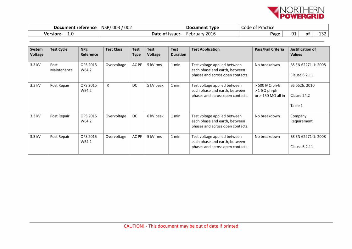
Document reference NSP/ 003 / 002 Document Type Code of Practice
Version:- 1.0 Date of Issue:- February 2016 Page 91 of 132
CAUTION! - This document may be out of date if printed
System Voltage
Test Cycle NPg Reference
Test Class Test Type
Test Voltage
Test Duration
Test Application Pass/Fail Criteria Justification of Values
3.3 kV Post Maintenance
OPS 2015 WE4.2
Overvoltage AC PF 5 kV rms 1 min Test voltage applied between each phase and earth, between phases and across open contacts.
No breakdown BS EN 62271-1: 2008
Clause 6.2.11
3.3 kV Post Repair OPS 2015 WE4.2
IR DC 5 kV peak 1 min Test voltage applied between each phase and earth, between phases and across open contacts.
> 500 MΩ ph-E > 1 GΩ ph-ph or > 150 MΩ all in
BS 6626: 2010
Clause 24.2
Table 1
3.3 kV Post Repair OPS 2015 WE4.2
Overvoltage DC 6 kV peak 1 min Test voltage applied between each phase and earth, between phases and across open contacts.
No breakdown Company Requirement
3.3 kV Post Repair OPS 2015 WE4.2
Overvoltage AC PF 5 kV rms 1 min Test voltage applied between each phase and earth, between phases and across open contacts.
No breakdown BS EN 62271-1: 2008
Clause 6.2.11

Document reference NSP/ 003 / 002 Document Type Code of Practice
Version:- 1.0 Date of Issue:- February 2016 Page 92 of 132
CAUTION! - This document may be out of date if printed
3.8.2.2. 6.6 kV Non-Isolatable Switchgear
System Voltage
Test Cycle NPg Reference
Test Class Test Type
Test Voltage
Test Duration
Test Application Pass/Fail Criteria Justification of Values
6.6 kV Commissioning OPS 2015 WE4.2
IR DC 5 kV peak 1 min Test voltage applied between each phase and earth, between phases and across open contacts.
> 500 MΩ ph-E > 1 GΩ ph-ph or > 150 MΩ all in
BS 6626: 2010
Clause 24.2
Table 1
6.6 kV Commissioning OPS 2015 WE4.2
Overvoltage DC 12 kV peak 1 min Test voltage applied between each phase and earth, between phases and across open contacts.
No breakdown Company Requirement
6.6 kV Commissioning OPS 2015 WE4.2
Overvoltage AC PF 10 kV rms 1 min Test voltage applied between each phase and earth, between phases and across open contacts.
No breakdown BS EN 62271-1: 2008
Clause 6.2.11
6.6 kV Post Maintenance
OPS 2015 WE4.2
IR DC 5 kV peak 1 min Test voltage applied between each phase and earth, between phases and across open contacts.
> 500 MΩ ph-E > 1 GΩ ph-ph or > 150 MΩ all in
BS 6626: 2010
Clause 24.2
Table 1
6.6 kV Post Maintenance
OPS 2015 WE4.2
Overvoltage DC 12 kV peak 1 min Test voltage applied between each phase and earth, between phases and across open contacts.
No breakdown Company Requirement

Document reference NSP/ 003 / 002 Document Type Code of Practice
Version:- 1.0 Date of Issue:- February 2016 Page 93 of 132
CAUTION! - This document may be out of date if printed
System Voltage
Test Cycle NPg Reference
Test Class Test Type
Test Voltage
Test Duration
Test Application Pass/Fail Criteria Justification of Values
6.6 kV Post Maintenance
OPS 2015 WE4.2
Overvoltage AC PF 10 kV rms 1 min Test voltage applied between each phase and earth, between phases and across open contacts.
No breakdown BS EN 62271-1: 2008
Clause 6.2.11
6.6 kV Post Repair OPS 2015 WE4.2
IR DC 5 kV peak 1 min Test voltage applied between each phase and earth, between phases and across open contacts.
> 500 MΩ ph-E > 1 GΩ ph-ph or > 150 MΩ all in
BS 6626: 2010
Clause 24.2
Table 1
6.6 kV Post Repair OPS 2015 WE4.2
Overvoltage DC 12 kV peak 1 min Test voltage applied between each phase and earth, between phases and across open contacts.
No breakdown Company Requirement
6.6 kV Post Repair OPS 2015 WE4.2
Overvoltage AC PF 10 kV rms 1 min Test voltage applied between each phase and earth, between phases and across open contacts.
No breakdown BS EN 62271-1: 2008
Clause 6.2.11

Document reference NSP/ 003 / 002 Document Type Code of Practice
Version:- 1.0 Date of Issue:- February 2016 Page 94 of 132
CAUTION! - This document may be out of date if printed
3.8.2.3. 11 kV Non-Isolatable Switchgear
System Voltage
Test Cycle NPg Reference
Test Class Test Type
Test Voltage
Test Duration
Test Application Pass/Fail Criteria
11 kV Commissioning OPS 2015 WE4.2
IR DC 5 kV peak 1 min Test voltage applied between each phase and earth, between phases and across open contacts.
> 500 MΩ ph-E > 1 GΩ ph-ph or > 150 MΩ all in
BS 6626: 2010
Clause 24.2
Table 1
11 kV Commissioning OPS 2015 WE4.2
Overvoltage DC 20 kV peak 1 min Test voltage applied between each phase and earth, between phases and across open contacts.
No breakdown Company Requirement
11 kV Commissioning OPS 2015 WE4.2
Overvoltage AC PF 16 kV rms 1 min Test voltage applied between each phase and earth, between phases and across open contacts.
No breakdown BS EN 62271-1: 2008
Clause 6.2.11
11 kV Post Maintenance
OPS 2015 WE4.2
IR DC 5 kV peak 1 min Test voltage applied between each phase and earth, between phases and across open contacts.
> 500 MΩ ph-E > 1 GΩ ph-ph or > 150 MΩ all in
BS 6626: 2010
Clause 24.2
Table 1
11 kV Post Maintenance
OPS 2015 WE4.2
Overvoltage DC 20 kV peak 1 min Test voltage applied between each phase and earth, between phases and across open contacts.
No breakdown Company Requirement

Document reference NSP/ 003 / 002 Document Type Code of Practice
Version:- 1.0 Date of Issue:- February 2016 Page 95 of 132
CAUTION! - This document may be out of date if printed
System Voltage
Test Cycle NPg Reference
Test Class Test Type
Test Voltage
Test Duration
Test Application Pass/Fail Criteria
11 kV Post Maintenance
OPS 2015 WE4.2
Overvoltage AC PF 16 kV rms 1 min Test voltage applied between each phase and earth, between phases and across open contacts.
No breakdown BS EN 62271-1: 2008
Clause 6.2.11
11 kV Post Repair OPS 2015 WE4.2
IR DC 5 kV peak 1 min Test voltage applied between each phase and earth, between phases and across open contacts.
> 500 MΩ ph-E > 1 GΩ ph-ph or > 150 MΩ all in
BS 6626: 2010
Clause 24.2
Table 1
11 kV Post Repair OPS 2015 WE4.2
Overvoltage DC 20 kV peak 1 min Test voltage applied between each phase and earth, between phases and across open contacts.
No breakdown Company Requirement
11 kV Post Repair OPS 2015 WE4.2
Overvoltage AC PF 16 kV rms 1 min Test voltage applied between each phase and earth, between phases and across open contacts.
No breakdown BS EN 62271-1: 2008
Clause 6.2.11

Document reference NSP/ 003 / 002 Document Type Code of Practice
Version:- 1.0 Date of Issue:- February 2016 Page 96 of 132
CAUTION! - This document may be out of date if printed
3.8.2.4. 20 kV Non-Isolatable Switchgear
System Voltage
Test Cycle NPg Reference
Test Class Test Type
Test Voltage
Test Duration
Test Application Pass/Fail Criteria Justification of Values
20 kV Commissioning OPS 2015 WE4.2
IR DC 5 kV peak 1 min Test voltage applied between each phase and earth, between phases and across open contacts.
> 500 MΩ ph-E > 1 GΩ ph-ph or > 150 MΩ all in
BS 6626: 2010
Clause 24.2
Table 1
20 kV Commissioning OPS 2015 WE4.2
Overvoltage DC 37 kV peak 1 min Test voltage applied between each phase and earth, between phases and across open contacts.
No breakdown Company Requirement
20 kV Commissioning OPS 2015 WE4.2
Overvoltage AC PF 30 kV rms 1 min Test voltage applied between each phase and earth, between phases and across open contacts.
No breakdown BS EN 62271-1: 2008
Clause 6.2.11
20 kV Post Maintenance
OPS 2015 WE4.2
IR DC 5 kV peak 1 min Test voltage applied between each phase and earth, between phases and across open contacts.
> 500 MΩ ph-E > 1 GΩ ph-ph or > 150 MΩ all in
BS 6626: 2010
Clause 24.2
Table 1
20 kV Post Maintenance
OPS 2015 WE4.2
Overvoltage DC 37 kV peak 1 min Test voltage applied between each phase and earth, between phases and across open contacts.
No breakdown Company Requirement

Document reference NSP/ 003 / 002 Document Type Code of Practice
Version:- 1.0 Date of Issue:- February 2016 Page 97 of 132
CAUTION! - This document may be out of date if printed
System Voltage
Test Cycle NPg Reference
Test Class Test Type
Test Voltage
Test Duration
Test Application Pass/Fail Criteria Justification of Values
20 kV Post Maintenance
OPS 2015 WE4.2
Overvoltage AC PF 30 kV rms 1 min Test voltage applied between each phase and earth, between phases and across open contacts.
No breakdown BS EN 62271-1: 2008
Clause 6.2.11
20 kV Post Repair OPS 2015 WE4.2
IR DC 5 kV peak 1 min Test voltage applied between each phase and earth, between phases and across open contacts.
> 500 MΩ ph-E > 1 GΩ ph-ph or > 150 MΩ all in
BS 6626: 2010
Clause 24.2
Table 1
20 kV Post Repair OPS 2015 WE4.2
Overvoltage DC 37 kV peak 1 min Test voltage applied between each phase and earth, between phases and across open contacts.
No breakdown Company Requirement
20 kV Post Repair OPS 2015 WE4.2
Overvoltage AC PF 30 kV rms 1 min Test voltage applied between each phase and earth, between phases and across open contacts.
No breakdown BS EN 62271-1: 2008
Clause 6.2.11

Document reference NSP/ 003 / 002 Document Type Code of Practice
Version:- 1.0 Date of Issue:- February 2016 Page 98 of 132
CAUTION! - This document may be out of date if printed
3.8.2.5. 25 kV Non-Isolatable Switchgear
System Voltage
Test Cycle NPg Reference
Test Class Test Type
Test Voltage
Test Duration
Test Application Pass/Fail Criteria Justification of Values
25 kV Commissioning OPS 2015 WE4.2
IR DC 5 kV peak 1 min Test voltage applied between each phase and earth, between phases and across open contacts.
> 500 MΩ ph-E > 1 GΩ ph-ph or > 150 MΩ all in
BS 6626: 2010
Clause 24.2
Table 1
25 kV Commissioning OPS 2015 WE4.2
Overvoltage DC 37 kV peak 1 min Test voltage applied between each phase and earth, between phases and across open contacts.
No breakdown Company Requirement
25 kV Commissioning OPS 2015 WE4.2
Overvoltage AC PF 30 kV rms 1 min Test voltage applied between each phase and earth, between phases and across open contacts.
No breakdown BS EN 62271-1: 2008
Clause 6.2.11
25 kV Post Maintenance
OPS 2015 WE4.2
IR DC 5 kV peak 1 min Test voltage applied between each phase and earth, between phases and across open contacts.
> 500 MΩ ph-E > 1 GΩ ph-ph or > 150 MΩ all in
BS 6626: 2010
Clause 24.2
Table 1
25 kV Post Maintenance
OPS 2015 WE4.2
Overvoltage DC 37 kV peak 1 min Test voltage applied between each phase and earth, between phases and across open contacts.
No breakdown Company Requirement

Document reference NSP/ 003 / 002 Document Type Code of Practice
Version:- 1.0 Date of Issue:- February 2016 Page 99 of 132
CAUTION! - This document may be out of date if printed
System Voltage
Test Cycle NPg Reference
Test Class Test Type
Test Voltage
Test Duration
Test Application Pass/Fail Criteria Justification of Values
25 kV Post Maintenance
OPS 2015 WE4.2
Overvoltage AC PF 30 kV rms 1 min Test voltage applied between each phase and earth, between phases and across open contacts.
No breakdown BS EN 62271-1: 2008
Clause 6.2.11
25 kV Post Repair OPS 2015 WE4.2
IR DC 5 kV peak 1 min Test voltage applied between each phase and earth, between phases and across open contacts.
> 500 MΩ ph-E > 1 GΩ ph-ph or > 150 MΩ all in
BS 6626: 2010
Clause 24.2
Table 1
25 kV Post Repair OPS 2015 WE4.2
Overvoltage DC 37 kV peak 1 min Test voltage applied between each phase and earth, between phases and across open contacts.
No breakdown Company Requirement
25 kV Post Repair OPS 2015 WE4.2
Overvoltage AC PF 30 kV rms 1 min Test voltage applied between each phase and earth, between phases and across open contacts.
No breakdown BS EN 62271-1: 2008
Clause 6.2.11

Document reference NSP/ 003 / 002 Document Type Code of Practice
Version:- 1.0 Date of Issue:- February 2016 Page 100 of 132
CAUTION! - This document may be out of date if printed
3.8.2.6. 33 kV Non-Isolatable Switchgear
System Voltage
Test Cycle NPg Reference
Test Class Test Type
Test Voltage
Test Duration
Test Application Pass/Fail Criteria Justification of Values
33 kV Commissioning OPS 2015 WE4.2
IR DC 5 kV peak 1 min Test voltage applied between each phase and earth, between phases and across open contacts.
> 500 MΩ ph-E > 1 GΩ ph-ph or > 150 MΩ all in
BS 6626: 2010
Clause 24.2
Table 1
33 kV Commissioning OPS 2015 WE4.2
Overvoltage DC 50 kV peak 1 min Test voltage applied between each phase and earth, between phases and across open contacts.
No breakdown Company Requirement
33 kV Commissioning OPS 2015 WE4.2
Overvoltage AC PF 50 kV rms 1 min Test voltage applied between each phase and earth, between phases and across open contacts.
No breakdown BS EN 62271-1: 2008
Clause 6.2.11
33 kV Post Maintenance
OPS 2015 WE4.2
IR DC 5 kV peak 1 min Test voltage applied between each phase and earth, between phases and across open contacts.
> 500 MΩ ph-E > 1 GΩ ph-ph or > 150 MΩ all in
BS 6626: 2010
Clause 24.2
Table 1
33 kV Post Maintenance
OPS 2015 WE4.2
Overvoltage DC 50 kV peak 1 min Test voltage applied between each phase and earth, between phases and across open contacts.
No breakdown Company Requirement

Document reference NSP/ 003 / 002 Document Type Code of Practice
Version:- 1.0 Date of Issue:- February 2016 Page 101 of 132
CAUTION! - This document may be out of date if printed
System Voltage
Test Cycle NPg Reference
Test Class Test Type
Test Voltage
Test Duration
Test Application Pass/Fail Criteria Justification of Values
33 kV Post Maintenance
OPS 2015 WE4.2
Overvoltage AC PF 50 kV rms 1 min Test voltage applied between each phase and earth, between phases and across open contacts.
No breakdown BS EN 62271-1: 2008
Clause 6.2.11
33 kV Post Repair OPS 2015 WE4.2
IR DC 5 kV peak 1 min Test voltage applied between each phase and earth, between phases and across open contacts.
> 500 MΩ ph-E > 1 GΩ ph-ph or > 150 MΩ all in
BS 6626: 2010
Clause 24.2
Table 1
33 kV Post Repair OPS 2015 WE4.2
Overvoltage DC 50 kV peak 1 min Test voltage applied between each phase and earth, between phases and across open contacts.
No breakdown Company Requirement
33 kV Post Repair OPS 2015 WE4.2
Overvoltage AC PF 50 kV rms 1 min Test voltage applied between each phase and earth, between phases and across open contacts.
No breakdown BS EN 62271-1: 2008
Clause 6.2.11

Document reference NSP/ 003 / 002 Document Type Code of Practice
Version:- 1.0 Date of Issue:- February 2016 Page 102 of 132
CAUTION! - This document may be out of date if printed
3.8.2.7. 66 kV Non-Isolatable Switchgear
System Voltage
Test Cycle NPg Reference
Test Class Test Type
Test Voltage
Test Duration
Test Application Pass/Fail Criteria Justification of Values
66 kV Commissioning OPS 2015 WE4.2
IR DC 5 kV peak 1 min Test voltage applied between each phase and earth, between phases and across open contacts.
> 500 MΩ ph-E > 1 GΩ ph-ph or > 150 MΩ all in
BS 6626: 2010
Clause 24.2
Table 1
66 kV Commissioning OPS 2015 WE4.2
Overvoltage DC 100 kV peak
1 min Test voltage applied between each phase and earth, between phases and across open contacts.
No breakdown Company Requirement
66 kV Commissioning OPS 2015 WE4.2
Overvoltage AC PF 85 kV rms 1 min Test voltage applied between each phase and earth, between phases and across open contacts.
No breakdown BS EN 62271-1: 2008
Clause 6.2.11
66 kV Post Maintenance
OPS 2015 WE4.2
IR DC 5 kV peak 1 min Test voltage applied between each phase and earth, between phases and across open contacts.
> 500 MΩ ph-E > 1 GΩ ph-ph or > 150 MΩ all in
BS 6626: 2010
Clause 24.2
Table 1
66 kV Post Maintenance
OPS 2015 WE4.2
Overvoltage DC 100 kV peak
1 min Test voltage applied between each phase and earth, between phases and across open contacts.
No breakdown Company Requirement

Document reference NSP/ 003 / 002 Document Type Code of Practice
Version:- 1.0 Date of Issue:- February 2016 Page 103 of 132
CAUTION! - This document may be out of date if printed
System Voltage
Test Cycle NPg Reference
Test Class Test Type
Test Voltage
Test Duration
Test Application Pass/Fail Criteria Justification of Values
66 kV Post Maintenance
OPS 2015 WE4.2
Overvoltage AC PF 85 kV rms 1 min Test voltage applied between each phase and earth, between phases and across open contacts.
No breakdown BS EN 62271-1: 2008
Clause 6.2.11
66 kV Post Repair OPS 2015 WE4.2
IR DC 5 kV peak 1 min Test voltage applied between each phase and earth, between phases and across open contacts.
> 500 MΩ ph-E > 1 GΩ ph-ph or > 150 MΩ all in
BS 6626: 2010
Clause 24.2
Table 1
66 kV Post Repair OPS 2015 WE4.2
Overvoltage DC 100 kV peak
1 min Test voltage applied between each phase and earth, between phases and across open contacts.
No breakdown Company Requirement
66 kV Post Repair OPS 2015 WE4.2
Overvoltage AC PF 85 kV rms 1 min Test voltage applied between each phase and earth, between phases and across open contacts.
No breakdown BS EN 62271-1: 2008
Clause 6.2.11

Document reference NSP/ 003 / 002 Document Type Code of Practice
Version:- 1.0 Date of Issue:- February 2016 Page 104 of 132
CAUTION! - This document may be out of date if printed
3.8.2.8. 132 kV Non-Isolatable Switchgear
System Voltage
Test Cycle NPg Reference
Test Class Test Type
Test Voltage
Test Duration
Test Application Pass/Fail Criteria Justification of Values
132 kV Commissioning OPS 2015 WE4.2
IR DC 5 kV peak 1 min Test voltage applied between each phase and earth, between phases and across open contacts.
> 500 MΩ ph-E > 1 GΩ ph-ph or > 150 MΩ all in
BS 6626: 2010
Clause 24.2
Table 1
132 kV Commissioning OPS 2015 WE4.2
Overvoltage DC 200 kV peak
1 min Test voltage applied between each phase and earth, between phases and across open contacts.
No breakdown Company Requirement
132 kV Commissioning OPS 2015 WE4.2
Overvoltage AC PF 150 kV rms 1 min Test voltage applied between each phase and earth, between phases and across open contacts.
No breakdown BS EN 62271-1: 2008
Clause 6.2.11
132 kV Post Maintenance
OPS 2015 WE4.2
IR DC 5 kV peak 1 min Test voltage applied between each phase and earth, between phases and across open contacts.
> 500 MΩ ph-E > 1 GΩ ph-ph or > 150 MΩ all in
BS 6626: 2010
Clause 24.2
Table 1
132 kV Post Maintenance
OPS 2015 WE4.2
Overvoltage DC 200 kV peak
1 min Test voltage applied between each phase and earth, between phases and across open contacts.
No breakdown Company Requirement

Document reference NSP/ 003 / 002 Document Type Code of Practice
Version:- 1.0 Date of Issue:- February 2016 Page 105 of 132
CAUTION! - This document may be out of date if printed
System Voltage
Test Cycle NPg Reference
Test Class Test Type
Test Voltage
Test Duration
Test Application Pass/Fail Criteria Justification of Values
132 kV Post Maintenance
OPS 2015 WE4.2
Overvoltage AC PF 150 kV rms 1 min Test voltage applied between each phase and earth, between phases and across open contacts.
No breakdown BS EN 62271-1: 2008
Clause 6.2.11
132 kV Post Repair OPS 2015 WE4.2
IR DC 5 kV peak 1 min Test voltage applied between each phase and earth, between phases and across open contacts.
> 500 MΩ ph-E > 1 GΩ ph-ph or > 150 MΩ all in
BS 6626: 2010
Clause 24.2
Table 1
132 kV Post Repair OPS 2015 WE4.2
Overvoltage DC 200 kV peak
1 min Test voltage applied between each phase and earth, between phases and across open contacts.
No breakdown Company Requirement
132 kV Post Repair OPS 2015 WE4.2
Overvoltage AC PF 150 kV rms 1 min Test voltage applied between each phase and earth, between phases and across open contacts.
No breakdown BS EN 62271-1: 2008
Clause 6.2.11

Document reference NSP/ 003 / 002 Document Type Code of Practice
Version:- 1.0 Date of Issue:- February 2016 Page 106 of 132
CAUTION! - This document may be out of date if printed
3.9. Transformers
3.9.1. Ground mounted transformers
3.9.1.1. 3.3 kV Ground Mounted Transformers
System Voltage
Test Cycle NPg Reference
Test Class Test Type
Test Voltage
Test Duration
Test Application Pass/Fail Criteria Justification of Values
3.3 kV Commissioning OPS 2015 WE4.3
Overvoltage DC 6 kV peak 15 min Test voltage applied to windings and tested to earth with all other windings earthed. Where HV cables are connected, they shall be tested as one unit using the DC test voltage to earth.
No breakdown Company Requirement
3.3 kV Commissioning OPS 2015 WE4.3
Overvoltage AC PF 5 kV rms 1 min Test voltage applied to windings and tested to earth with all other windings earthed. Where HV cables are connected, they shall be tested as one unit using the DC test voltage to earth.
No breakdown BS EN 60076-3: 2013
Clause 8
Reduced value
3.3 kV Post Maintenance
OPS 2015 WE4.3
Overvoltage DC 6 kV peak 15 min Test voltage applied to windings and tested to earth with all other windings earthed. Where HV cables are connected, they shall be tested as one unit using the DC test voltage to earth.
No breakdown Company Requirement

Document reference NSP/ 003 / 002 Document Type Code of Practice
Version:- 1.0 Date of Issue:- February 2016 Page 107 of 132
CAUTION! - This document may be out of date if printed
System Voltage
Test Cycle NPg Reference
Test Class Test Type
Test Voltage
Test Duration
Test Application Pass/Fail Criteria Justification of Values
3.3 kV Post Maintenance
OPS 2015 WE4.3
Overvoltage AC PF 5 kV rms 1 min Test voltage applied to windings and tested to earth with all other windings earthed. Where HV cables are connected, they shall be tested as one unit using the DC test voltage to earth.
No breakdown BS EN 60076-3: 2013
Clause 8
Reduced value
3.3 kV Post Repair OPS 2015 WE4.3
Overvoltage DC 6 kV peak 15 min Test voltage applied to windings and tested to earth with all other windings earthed. Where HV cables are connected, they shall be tested as one unit using the DC test voltage to earth.
No breakdown Company Requirement
3.3 kV Post Repair OPS 2015 WE4.3
Overvoltage AC PF 5 kV rms 1 min Test voltage applied to windings and tested to earth with all other windings earthed. Where HV cables are connected, they shall be tested as one unit using the DC test voltage to earth.
No breakdown BS EN 60076-3: 2013
Clause 8
Reduced value

Document reference NSP/ 003 / 002 Document Type Code of Practice
Version:- 1.0 Date of Issue:- February 2016 Page 108 of 132
CAUTION! - This document may be out of date if printed
3.9.1.2. 6.6 kV Ground Mounted Transformers
System Voltage
Test Cycle NPg Reference
Test Class Test Type
Test Voltage
Test Duration
Test Application Pass/Fail Criteria Justification of Values
6.6 kV Commissioning OPS 2015 WE4.3
Overvoltage DC 12 kV peak 15 min Test voltage applied to windings and tested to earth with all other windings earthed. Where HV cables are connected, they shall be tested as one unit using the DC test voltage to earth.
No breakdown Company Requirement
6.6 kV Commissioning OPS 2015 WE4.3
Overvoltage AC PF 10 kV rms 1 min Test voltage applied to windings and tested to earth with all other windings earthed. Where HV cables are connected, they shall be tested as one unit using the DC test voltage to earth.
No breakdown BS EN 60076-3: 2013
Clause 8
Reduced value
6.6 kV Post Maintenance
OPS 2015 WE4.3
Overvoltage DC 12 kV peak 15 min Test voltage applied to windings and tested to earth with all other windings earthed. Where HV cables are connected, they shall be tested as one unit using the DC test voltage to earth.
No breakdown Company Requirement

Document reference NSP/ 003 / 002 Document Type Code of Practice
Version:- 1.0 Date of Issue:- February 2016 Page 109 of 132
CAUTION! - This document may be out of date if printed
System Voltage
Test Cycle NPg Reference
Test Class Test Type
Test Voltage
Test Duration
Test Application Pass/Fail Criteria Justification of Values
6.6 kV Post Maintenance
OPS 2015 WE4.3
Overvoltage AC PF 10 kV rms 1 min Test voltage applied to windings and tested to earth with all other windings earthed. Where HV cables are connected, they shall be tested as one unit using the DC test voltage to earth.
No breakdown BS EN 60076-3: 2013
Clause 8
Reduced value
6.6 kV Post Repair OPS 2015 WE4.3
Overvoltage DC 12 kV peak 15 min Test voltage applied to windings and tested to earth with all other windings earthed. Where HV cables are connected, they shall be tested as one unit using the DC test voltage to earth.
No breakdown Company Requirement
6.6 kV Post Repair OPS 2015 WE4.3
Overvoltage AC PF 10 kV rms 1 min Test voltage applied to windings and tested to earth with all other windings earthed. Where HV cables are connected, they shall be tested as one unit using the DC test voltage to earth.
No breakdown BS EN 60076-3: 2013
Clause 8
Reduced value

Document reference NSP/ 003 / 002 Document Type Code of Practice
Version:- 1.0 Date of Issue:- February 2016 Page 110 of 132
CAUTION! - This document may be out of date if printed
3.9.1.3. 11 kV Ground Mounted Transformers
System Voltage
Test Cycle NPg Reference
Test Class Test Type
Test Voltage
Test Duration
Test Application Pass/Fail Criteria Justification of Values
11 kV Commissioning OPS 2015 WE4.3
Overvoltage DC 20 kV peak 15 min Test voltage applied to windings and tested to earth with all other windings earthed. Where HV cables are connected, they shall be tested as one unit using the DC test voltage to earth.
No breakdown Company Requirement
11 kV Commissioning OPS 2015 WE4.3
Overvoltage AC PF 16 kV rms 1 min Test voltage applied to windings and tested to earth with all other windings earthed. Where HV cables are connected, they shall be tested as one unit using the DC test voltage to earth.
No breakdown BS EN 60076-3: 2013
Clause 8
Reduced value
11 kV Post Maintenance
OPS 2015 WE4.3
Overvoltage DC 20 kV peak 15 min Test voltage applied to windings and tested to earth with all other windings earthed. Where HV cables are connected, they shall be tested as one unit using the DC test voltage to earth.
No breakdown Company Requirement

Document reference NSP/ 003 / 002 Document Type Code of Practice
Version:- 1.0 Date of Issue:- February 2016 Page 111 of 132
CAUTION! - This document may be out of date if printed
System Voltage
Test Cycle NPg Reference
Test Class Test Type
Test Voltage
Test Duration
Test Application Pass/Fail Criteria Justification of Values
11 kV Post Maintenance
OPS 2015 WE4.3
Overvoltage AC PF 16 kV rms 1 min Test voltage applied to windings and tested to earth with all other windings earthed. Where HV cables are connected, they shall be tested as one unit using the DC test voltage to earth.
No breakdown BS EN 60076-3: 2013
Clause 8
Reduced value
11 kV Post Repair OPS 2015 WE4.3
Overvoltage DC 20 kV peak 15 min Test voltage applied to windings and tested to earth with all other windings earthed. Where HV cables are connected, they shall be tested as one unit using the DC test voltage to earth.
No breakdown Company Requirement
11 kV Post Repair OPS 2015 WE4.3
Overvoltage AC PF 16 kV rms 1 min Test voltage applied to windings and tested to earth with all other windings earthed. Where HV cables are connected, they shall be tested as one unit using the DC test voltage to earth.
No breakdown BS EN 60076-3: 2013
Clause 8
Reduced value

Document reference NSP/ 003 / 002 Document Type Code of Practice
Version:- 1.0 Date of Issue:- February 2016 Page 112 of 132
CAUTION! - This document may be out of date if printed
3.9.1.4. 20 kV Ground Mounted Transformers
System Voltage
Test Cycle NPg Reference
Test Class Test Type
Test Voltage
Test Duration
Test Application Pass/Fail Criteria Justification of Values
20 kV Commissioning OPS 2015 WE4.3
Overvoltage DC 37 kV peak 15 min Test voltage applied to windings and tested to earth with all other windings earthed. Where HV cables are connected, they shall be tested as one unit using the DC test voltage to earth.
No breakdown Company Requirement
20 kV Commissioning OPS 2015 WE4.3
Overvoltage AC PF 30 kV rms 1 min Test voltage applied to windings and tested to earth with all other windings earthed. Where HV cables are connected, they shall be tested as one unit using the DC test voltage to earth.
No breakdown BS EN 60076-3: 2013
Clause 8
Reduced value
20 kV Post Maintenance
OPS 2015 WE4.3
Overvoltage DC 37 kV peak 15 min Test voltage applied to windings and tested to earth with all other windings earthed. Where HV cables are connected, they shall be tested as one unit using the DC test voltage to earth.
No breakdown Company Requirement

Document reference NSP/ 003 / 002 Document Type Code of Practice
Version:- 1.0 Date of Issue:- February 2016 Page 113 of 132
CAUTION! - This document may be out of date if printed
System Voltage
Test Cycle NPg Reference
Test Class Test Type
Test Voltage
Test Duration
Test Application Pass/Fail Criteria Justification of Values
20 kV Post Maintenance
OPS 2015 WE4.3
Overvoltage AC PF 30 kV rms 1 min Test voltage applied to windings and tested to earth with all other windings earthed. Where HV cables are connected, they shall be tested as one unit using the DC test voltage to earth.
No breakdown BS EN 60076-3: 2013
Clause 8
Reduced value
20 kV Post Repair OPS 2015 WE4.3
Overvoltage DC 37 kV peak 15 min Test voltage applied to windings and tested to earth with all other windings earthed. Where HV cables are connected, they shall be tested as one unit using the DC test voltage to earth.
No breakdown Company Requirement
20 kV Post Repair OPS 2015 WE4.3
Overvoltage AC PF 30 kV rms 1 min Test voltage applied to windings and tested to earth with all other windings earthed. Where HV cables are connected, they shall be tested as one unit using the DC test voltage to earth.
No breakdown BS EN 60076-3: 2013
Clause 8
Reduced value

Document reference NSP/ 003 / 002 Document Type Code of Practice
Version:- 1.0 Date of Issue:- February 2016 Page 114 of 132
CAUTION! - This document may be out of date if printed
3.9.1.5. 25 kV Ground Mounted Transformers
System Voltage
Test Cycle NPg Reference
Test Class Test Type
Test Voltage
Test Duration
Test Application Pass/Fail Criteria Justification of Values
25 kV Commissioning OPS 2015 WE4.3.1
IR DC 5 kV peak 1 min Test voltage applied to windings and tested to earth with all other windings earthed.
> 150 MΩ Company Requirement
25 kV Post Maintenance
OPS 2015 WE4.3.1 OPS 2015 WE4.3.2
IR DC 5 kV peak 1 min Test voltage applied to windings and tested to earth with all other windings earthed.
> 150 MΩ Company Requirement
25 kV Post Repair OPS 2015 WE4.3.1 OPS 2015 WE4.3.2
Diagnostic AC PF 10 kV rms N/A Single phase excitation tests Comparative Company Requirement
25 kV Post Repair OPS 2015 WE4.3.1 OPS 2015 WE4.3.2
Diagnostic DGA N/A N/A Dissolved gas in oil. Comparative Company Requirement
25 kV Post Repair OPS 2015 WE4.3.1 OPS 2015 WE4.3.3
Diagnostic FRA N/A N/A Frequency response analysis. Comparative Company Requirement

Document reference NSP/ 003 / 002 Document Type Code of Practice
Version:- 1.0 Date of Issue:- February 2016 Page 115 of 132
CAUTION! - This document may be out of date if printed
3.9.1.6. 33 kV Ground Mounted Transformers
System Voltage
Test Cycle NPg Reference
Test Class Test Type
Test Voltage
Test Duration
Test Application Pass/Fail Criteria Justification of Values
33 kV Commissioning OPS 2015 WE4.3.1
IR DC 5 kV peak 1 min Test voltage applied to windings and tested to earth with all other windings earthed.
> 150 MΩ Company Requirement
33 kV Post Maintenance
OPS 2015 WE4.3.1 OPS 2015 WE4.3.2
IR DC 5 kV peak 1 min Test voltage applied to windings and tested to earth with all other windings earthed.
> 150 MΩ Company Requirement
33 kV Post Repair OPS 2015 WE4.3.1 OPS 2015 WE4.3.2
Diagnostic AC PF 10 kV rms N/A Single phase excitation tests Comparative Company Requirement
33 kV Post Repair OPS 2015 WE4.3.1 OPS 2015 WE4.3.2
Diagnostic DGA N/A N/A Dissolved gas in oil. Comparative Company Requirement
33 kV Post Repair OPS 2015 WE4.3.1 OPS 2015 WE4.3.3
Diagnostic FRA N/A N/A Frequency response analysis. Comparative Company Requirement

Document reference NSP/ 003 / 002 Document Type Code of Practice
Version:- 1.0 Date of Issue:- February 2016 Page 116 of 132
CAUTION! - This document may be out of date if printed
3.9.1.7. 66 kV Ground Mounted Transformers
System Voltage
Test Cycle NPg Reference
Test Class Test Type
Test Voltage
Test Duration
Test Application Pass/Fail Criteria Justification of Values
66 kV Commissioning OPS 2015 WE4.3.1
IR DC 5 kV peak 1 min Test voltage applied to windings and tested to earth with all other windings earthed.
> 150 MΩ Company Requirement
66 kV Post Maintenance
OPS 2015 WE4.3.1 OPS 2015 WE4.3.2
IR DC 5 kV peak 1 min Test voltage applied to windings and tested to earth with all other windings earthed.
> 150 MΩ Company Requirement
66 kV Post Repair OPS 2015 WE4.3.1 OPS 2015 WE4.3.2
Diagnostic AC PF 10 kV rms N/A Single phase excitation tests Comparative Company Requirement
66 kV Post Repair OPS 2015 WE4.3.1 OPS 2015 WE4.3.2
Diagnostic DGA N/A N/A Dissolved gas in oil. Comparative Company Requirement
66 kV Post Repair OPS 2015 WE4.3.1 OPS 2015 WE4.3.3
Diagnostic FRA N/A N/A Frequency response analysis. Comparative Company Requirement

Document reference NSP/ 003 / 002 Document Type Code of Practice
Version:- 1.0 Date of Issue:- February 2016 Page 117 of 132
CAUTION! - This document may be out of date if printed
3.9.1.8. 132 kV Ground Mounted Transformers
System Voltage
Test Cycle NPg Reference
Test Class Test Type
Test Voltage
Test Duration
Test Application Pass/Fail Criteria
132 kV Commissioning OPS 2015 WE4.3.1
IR DC 5 kV peak 1 min Test voltage applied to windings and tested to earth with all other windings earthed.
> 150 MΩ Company Requirement
132 kV Post Maintenance
OPS 2015 WE4.3.1 OPS 2015 WE4.3.2
IR DC 5 kV peak 1 min Test voltage applied to windings and tested to earth with all other windings earthed.
> 150 MΩ Company Requirement
132 kV Post Repair OPS 2015 WE4.3.1 OPS 2015 WE4.3.2
Diagnostic AC PF 10 kV rms N/A Single phase excitation tests Comparative Company Requirement
132 kV Post Repair OPS 2015 WE4.3.1 OPS 2015 WE4.3.2
Diagnostic DGA N/A N/A Dissolved gas in oil. Comparative Company Requirement
132 kV Post Repair OPS 2015 WE4.3.1 OPS 2015 WE4.3.3
Diagnostic FRA N/A N/A Frequency response analysis. Comparative Company Requirement

Document reference NSP/ 003 / 002 Document Type Code of Practice
Version:- 1.0 Date of Issue:- February 2016 Page 118 of 132
CAUTION! - This document may be out of date if printed
3.9.2. Instrument transformers
3.9.2.1. 3.3 kV Instrument Transformers
System Voltage
Test Cycle NPg Reference
Test Class Test Type
Test Voltage
Test Duration
Test Application Pass/Fail Criteria Justification of Values
3.3 kV Commissioning OPS 2015 WE4.3
Overvoltage AC PF 2 kV rms 1 min Test voltage applied to high voltage winding with low voltage winding earthed. Low voltage winding tested to earth at 500 V DC.
No breakdown BS EN 61869-1: 2009
Clause 7.3.1. Table 2
Reduced value
3.3 kV Post Maintenance
OPS 2015 WE4.3
Overvoltage AC PF 2 kV rms 1 min Test voltage applied to high voltage winding with low voltage winding earthed. Low voltage winding tested to earth at 500 V DC.
No breakdown BS EN 61869-1: 2009
Clause 7.3.1. Table 2
Reduced value
3.3 kV Post Repair OPS 2015 WE4.3
Overvoltage AC PF 2 kV rms 1 min Test voltage applied to high voltage winding with low voltage winding earthed. Low voltage winding tested to earth at 500 V DC.
No breakdown BS EN 61869-1: 2009
Clause 7.3.1. Table 2
Reduced value

Document reference NSP/ 003 / 002 Document Type Code of Practice
Version:- 1.0 Date of Issue:- February 2016 Page 119 of 132
CAUTION! - This document may be out of date if printed
3.9.2.2. 6.6 kV Instrument Transformers
System Voltage
Test Cycle NPg Reference
Test Class Test Type
Test Voltage
Test Duration
Test Application Pass/Fail Criteria Justification of Values
6.6 kV Commissioning OPS 2015 WE4.3
Overvoltage AC PF 3.8 kV rms 1 min Test voltage applied to high voltage winding with low voltage winding earthed. Low voltage winding tested to earth at 500 V DC.
No breakdown BS EN 61869-1: 2009
Clause 7.3.1. Table 2
Reduced value
6.6 kV Post Maintenance
OPS 2015 WE4.3
Overvoltage AC PF 3.8 kV rms 1 min Test voltage applied to high voltage winding with low voltage winding earthed. Low voltage winding tested to earth at 500 V DC.
No breakdown BS EN 61869-1: 2009
Clause 7.3.1. Table 2
Reduced value
6.6 kV Post Repair OPS 2015 WE4.3
Overvoltage AC PF 3.8 kV rms 1 min Test voltage applied to high voltage winding with low voltage winding earthed. Low voltage winding tested to earth at 500 V DC.
No breakdown BS EN 61869-1: 2009
Clause 7.3.1. Table 2
Reduced value

Document reference NSP/ 003 / 002 Document Type Code of Practice
Version:- 1.0 Date of Issue:- February 2016 Page 120 of 132
CAUTION! - This document may be out of date if printed
3.9.2.3. 11 kV Instrument Transformers
System Voltage
Test Cycle NPg Reference
Test Class Test Type
Test Voltage
Test Duration
Test Application Pass/Fail Criteria Justification of Values
11 kV Commissioning OPS 2015 WE4.3
Overvoltage AC PF 6.4 kV rms 1 min Test voltage applied to high voltage winding with low voltage winding earthed. Low voltage winding tested to earth at 500 V DC.
No breakdown BS EN 61869-1: 2009
Clause 7.3.1. Table 2
Reduced value
11 kV Post Maintenance
OPS 2015 WE4.3
Overvoltage AC PF 6.4 kV rms 1 min Test voltage applied to high voltage winding with low voltage winding earthed. Low voltage winding tested to earth at 500 V DC.
No breakdown BS EN 61869-1: 2009
Clause 7.3.1. Table 2
Reduced value
11 kV Post Repair OPS 2015 WE4.3
Overvoltage AC PF 6.4 kV rms 1 min Test voltage applied to high voltage winding with low voltage winding earthed. Low voltage winding tested to earth at 500 V DC.
No breakdown BS EN 61869-1: 2009
Clause 7.3.1. Table 2
Reduced value

Document reference NSP/ 003 / 002 Document Type Code of Practice
Version:- 1.0 Date of Issue:- February 2016 Page 121 of 132
CAUTION! - This document may be out of date if printed
3.9.2.4. 20 kV Instrument Transformers
System Voltage
Test Cycle NPg Reference
Test Class Test Type
Test Voltage
Test Duration
Test Application Pass/Fail Criteria Justification of Values
20 kV Commissioning OPS 2015 WE4.3
Overvoltage AC PF 11.5 kV rms
1 min Test voltage applied to high voltage winding with low voltage winding earthed. Low voltage winding tested to earth at 500 V DC.
No breakdown BS EN 61869-1: 2009
Clause 7.3.1. Table 2
Reduced value
20 kV Post Maintenance
OPS 2015 WE4.3
Overvoltage AC PF 11.5 kV rms
1 min Test voltage applied to high voltage winding with low voltage winding earthed. Low voltage winding tested to earth at 500 V DC.
No breakdown BS EN 61869-1: 2009
Clause 7.3.1. Table 2
Reduced value
20 kV Post Repair OPS 2015 WE4.3
Overvoltage AC PF 11.5 kV rms
1 min Test voltage applied to high voltage winding with low voltage winding earthed. Low voltage winding tested to earth at 500 V DC.
No breakdown BS EN 61869-1: 2009
Clause 7.3.1. Table 2
Reduced value

Document reference NSP/ 003 / 002 Document Type Code of Practice
Version:- 1.0 Date of Issue:- February 2016 Page 122 of 132
CAUTION! - This document may be out of date if printed
3.9.2.5. 25 kV Instrument Transformers
System Voltage
Test Cycle NPg Reference
Test Class Test Type
Test Voltage
Test Duration
Test Application Pass/Fail Criteria Justification of Values
25 kV Commissioning OPS 2015 WE4.3
Overvoltage AC PF 14.4 kV rms
1 min Test voltage applied to high voltage winding with low voltage winding earthed. Low voltage winding tested to earth at 500 V DC.
No breakdown BS EN 61869-1: 2009
Clause 7.3.1. Table 2
Reduced value
25 kV Post Maintenance
OPS 2015 WE4.3
Overvoltage AC PF 14.4 kV rms
1 min Test voltage applied to high voltage winding with low voltage winding earthed. Low voltage winding tested to earth at 500 V DC.
No breakdown BS EN 61869-1: 2009
Clause 7.3.1. Table 2
Reduced value
25 kV Post Repair OPS 2015 WE4.3
Overvoltage AC PF 14.4 kV rms
1 min Test voltage applied to high voltage winding with low voltage winding earthed. Low voltage winding tested to earth at 500 V DC.
No breakdown BS EN 61869-1: 2009
Clause 7.3.1. Table 2
Reduced value

Document reference NSP/ 003 / 002 Document Type Code of Practice
Version:- 1.0 Date of Issue:- February 2016 Page 123 of 132
CAUTION! - This document may be out of date if printed
3.9.2.6. 33 kV Instrument Transformers
System Voltage
Test Cycle NPg Reference
Test Class Test Type
Test Voltage
Test Duration
Test Application Pass/Fail Criteria Justification of Values
33 kV Commissioning OPS 2015 WE4.3
Overvoltage AC PF 19 kV rms 1 min Test voltage applied to high voltage winding with low voltage winding earthed. Low voltage winding tested to earth at 500 V DC.
No breakdown BS EN 61869-1: 2009
Clause 7.3.1. Table 2
Reduced value
33 kV Post Maintenance
OPS 2015 WE4.3
Overvoltage AC PF 19 kV rms 1 min Test voltage applied to high voltage winding with low voltage winding earthed. Low voltage winding tested to earth at 500 V DC.
No breakdown BS EN 61869-1: 2009
Clause 7.3.1. Table 2
Reduced value
33 kV Post Repair OPS 2015 WE4.3
Overvoltage AC PF 19 kV rms 1 min Test voltage applied to high voltage winding with low voltage winding earthed. Low voltage winding tested to earth at 500 V DC.
No breakdown BS EN 61869-1: 2009
Clause 7.3.1. Table 2
Reduced value

Document reference NSP/ 003 / 002 Document Type Code of Practice
Version:- 1.0 Date of Issue:- February 2016 Page 124 of 132
CAUTION! - This document may be out of date if printed
3.9.2.7. 66 kV Instrument Transformers
System Voltage
Test Cycle NPg Reference
Test Class Test Type
Test Voltage
Test Duration
Test Application Pass/Fail Criteria Justification of Values
66 kV Commissioning OPS 2015 WE4.3
Overvoltage AC PF 38 kV rms 1 min Test voltage applied to high voltage winding with low voltage winding earthed. Low voltage winding tested to earth at 500 V DC.
No breakdown BS EN 61869-1: 2009
Clause 7.3.1. Table 2
Reduced value
66 kV Post Maintenance
OPS 2015 WE4.3
Overvoltage AC PF 38 kV rms 1 min Test voltage applied to high voltage winding with low voltage winding earthed. Low voltage winding tested to earth at 500 V DC.
No breakdown BS EN 61869-1: 2009
Clause 7.3.1. Table 2
Reduced value
66 kV Post Repair OPS 2015 WE4.3
Overvoltage AC PF 38 kV rms 1 min Test voltage applied to high voltage winding with low voltage winding earthed. Low voltage winding tested to earth at 500 V DC.
No breakdown BS EN 61869-1: 2009
Clause 7.3.1. Table 2
Reduced value

Document reference NSP/ 003 / 002 Document Type Code of Practice
Version:- 1.0 Date of Issue:- February 2016 Page 125 of 132
CAUTION! - This document may be out of date if printed
3.9.2.8. 132 kV Instrument Transformers
System Voltage
Test Cycle NPg Reference
Test Class Test Type
Test Voltage
Test Duration
Test Application Pass/Fail Criteria Justification of Values
132 kV Commissioning OPS 2015 WE4.3
Overvoltage AC PF 76 kV rms 1 min Test voltage applied to high voltage winding with low voltage winding earthed. Low voltage winding tested to earth at 500 V DC.
No breakdown BS EN 61869-1: 2009
Clause 7.3.1. Table 2
Reduced value
132 kV Post Maintenance
OPS 2015 WE4.3
Overvoltage AC PF 76 kV rms 1 min Test voltage applied to high voltage winding with low voltage winding earthed. Low voltage winding tested to earth at 500 V DC.
No breakdown BS EN 61869-1: 2009
Clause 7.3.1. Table 2
Reduced value
132 kV Post Repair OPS 2015 WE4.3
Overvoltage AC PF 76 kV rms 1 min Test voltage applied to high voltage winding with low voltage winding earthed. Low voltage winding tested to earth at 500 V DC.
No breakdown BS EN 61869-1: 2009
Clause 7.3.1. Table 2
Reduced value

Document reference NSP/ 003 001 Document Type Code of Practice
Version:- 1.0 Date of Issue:- Page 126 of 132
CAUTION! - This document may be out of date if printed
4. References
4.1. External Documentation
Reference Title
IEC 60502-2: 2014
Power cables with extruded insulation and their accessories from 1 kV up to 30 kV.
BS EN 60060 High voltage test techniques.
BS EN 60076-3: 2013
Power transformers. Insulation levels, dielectric tests and external clearances in air.
BS EN 60076-18: 2012
Power transformers. Measurement of frequency response.
BS EN 61869-1:2009
Instrument transformers. General requirements.
BS EN 62271-1: 2008 + A1: 2011
High voltage switchgear and control gear. Common specifications.
BS 6622: 2007 Electric cables – Armoured cables with thermosetting insulation for rated voltages from 3.8/6/6 kV to 19/33 kV – Requirements and test methods.
BS 6626: 2010 Maintenance of electrical switchgear and control gear for voltages above 1 kV and up to and including 36 kV. Code of practice.
BS 7870 – 4.10: 2011
LV and MV polymeric insulated cables for use by distribution and generation utilities. Specification for distribution cables with extruded insulation of rated voltages of 11 kV to 33 kV. Single-core 11 kV to 33 kV cables.
BS 7912: 2012 Power cables with XLPE insulation and metal sheath, and their accessories, for rated voltages from 66 kV to 132 kV.
BS 7922: 2004
IEEE 400.2-2013
Guide for field testing of shielded power cable systems using VLF.
4.2. Internal documentation
Reference Title
OPM 2015 Northern Powergrid Operation Practice Manual 2015
4.3. Amendments from Previous Version
Reference Title
None
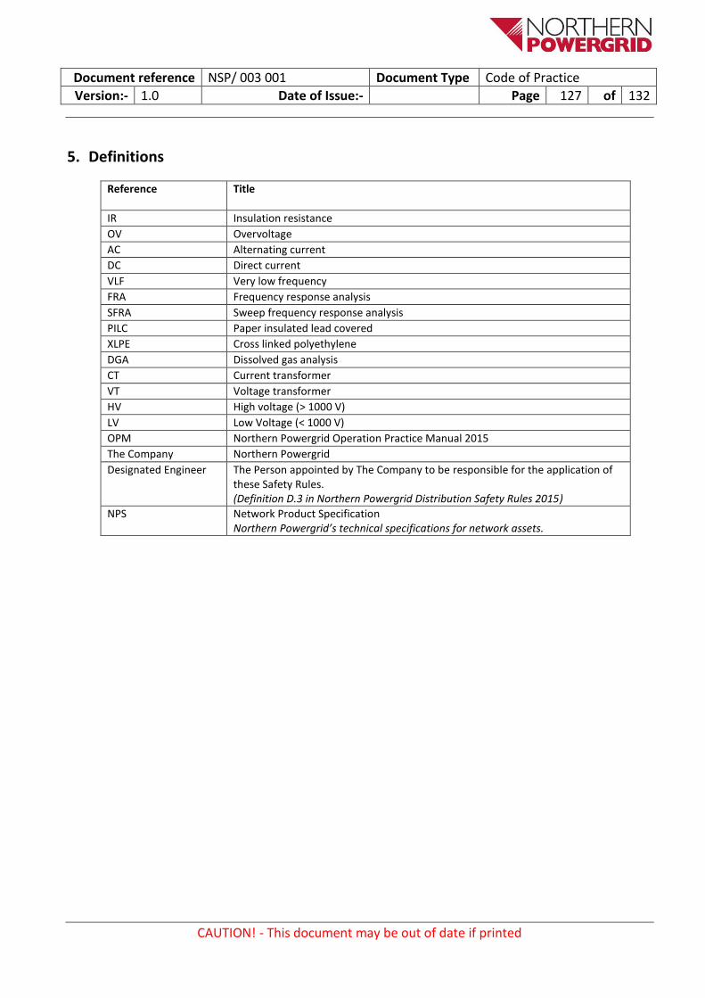
Document reference NSP/ 003 001 Document Type Code of Practice
Version:- 1.0 Date of Issue:- Page 127 of 132
CAUTION! - This document may be out of date if printed
5. Definitions
Reference Title
IR Insulation resistance
OV Overvoltage
AC Alternating current
DC Direct current
VLF Very low frequency
FRA Frequency response analysis
SFRA Sweep frequency response analysis
PILC Paper insulated lead covered
XLPE Cross linked polyethylene
DGA Dissolved gas analysis
CT Current transformer
VT Voltage transformer
HV High voltage (> 1000 V)
LV Low Voltage (< 1000 V)
OPM Northern Powergrid Operation Practice Manual 2015
The Company Northern Powergrid
Designated Engineer The Person appointed by The Company to be responsible for the application of these Safety Rules. (Definition D.3 in Northern Powergrid Distribution Safety Rules 2015)
NPS Network Product Specification Northern Powergrid’s technical specifications for network assets.

Document reference NSP/ 003 001 Document Type Code of Practice
Version:- 1.0 Date of Issue:- Page 128 of 132
CAUTION! - This document may be out of date if printed
6. Authority for issue 6.1. CDS Assurance
I sign to confirm that I have completed and checked this document and I am satisfied with its content and submit it for approval and authorisation.
Sign Date
Sarah Phillips CDS Administrator Sarah Phillips 03/02/16
6.2. Author
I sign to confirm that I have completed and checked this document and I am satisfied with its content and submit it for approval and authorisation.
Review Period - This document should be reviewed within the following time period.
Standard CDS review of 3 years Non Standard Review Period & Reason
Yes Period: Reason:
Sign Date
Iain Ross Threepwood Consulting N/A
03/02/16 David Blackledge
Senior Policy and Standards Engineer
David Blackledge
6.3. Technical Assurance
I sign to confirm that I am satisfied with all aspects of the content and preparation of this document and submit it for approval and authorisation.
Sign Date
Ged Hammel Senior Policy and Standards Engineer
Ged Hammel 03/02/16
6.4. Approval NOTE: Section 6.4 is not mandatory
Approval is granted for publication of this document.
Sign Date
Chris Holdsworth Policy & Standards Manager Chris Holdsworth 03/02/16
6.5. Authorisation
Authorisation is granted for publication of this document.
Sign Date
Mark Nicholson Head of System Strategy Mark Nicholson 09/02/16

Document reference NSP/ 003 001 Document Type Code of Practice
Version:- 1.0 Date of Issue:- Page 129 of 132
CAUTION! - This document may be out of date if printed
Appendix 1 – Testing Forms
A.1 Non-isolatable Switchgear
A.2 Isolatable Switchgear

A.1 HV Equipment Test Sheet (Non-Isolatable)
Substation:
Manufacturer/ Type:
Weather:
Voltage (kV):
I/D or O/D
Temp: Humidity:
Overvoltage Testing Details of Testing
Description Phases Voltage AC/DC/
VLF Duration Leakage
Test Equipment Serial # Calibration Due
Signature of Tester: Date:
Phase Feeder Route Excluding Txs
Transformer Loop
Feeder Route Including Txs
L1 – E
L2 – E
L3 – E
L1 – L2
L1 – L3
L2 – L3
All In
Where the equipment is connected to an Overhead
Line (which would not normally be tested),
sufficient testing is required to prove as much of the
maintained equipment as practicable
For Pole Mounted equipment the following values are acceptable;
Switchgear
Phase - Earth 100 MΩ
Phase - Phase 200 MΩ
Transformer
All In 50 MΩ
For values below these, engineering
judgment will be exercised taking into account environmental
conditions.
EQUIPMENT TO BE ENERGISED REMOTELY
Test Voltage / Duration: 5kV for 1 Min Indicate if readings are kΩ, GΩ or MΩ
Non-Isolatable Equipment
IR Value ≥ 500 MΩ Ph-E and ≥ 1 GΩ Ph – Ph
or 150 MΩ All In
Lowest value ≥ 50% of highest value? Yes
Energise equipment remotely with no-one present on site
Further investigations plus overvoltage test on equipment
Acceptable to energise with no
restrictions
Yes
IR Value ≥ 50 MΩ Ph-E and ≥ 100 MΩ Ph – Ph
or 15 MΩ All In
No
No
Yes
No Overvoltage test satisfactory?
Locate and repair fault
Yes

A.2 HV Equipment Test Sheet (Isolatable)
Substation:
Manufacturer/ Type:
Weather:
Voltage (kV):
I/D or O/D
Temp: Humidity:
Test Voltage / Duration: 5kV for 1 Min Indicate if readings are kΩ GΩ or MΩ
Isolatable Equipment
IR Value ≥ 2 GΩ Ph-E and ≥ 4 GΩ Ph – Ph
or 1 GΩ All In for Transformer or VT
Where practicable, change unit. If not practicable, overvoltage test and recommission with further
investigation as soon as possible Acceptable to recommission with no
restrictions
No
Yes
Circuit Name
Switch Position
Transformer / VT
Serial # HV LV
L1 – E
Closed
L2 – E
L3 – E
L1 – L2
L1 – L3
L2 – L3 All In
Continuity
L1 – L1
Open L2 – L2
L3 – L3
Overvoltage Testing Details of Testing
Description Phases Voltage AC/DC/
VLF Duration Leakage
Test Equipment Serial # Calibration Due
Signature of Tester: Date:

Document reference XXX/ - - - / - - - / - - - / - - - Document Type Code of Practice
Version:- Date of Issue:- Page 132 of 132
CAUTION! - This document may be out of date if printed
THIS PAGE DELIBERATELY LEFT BLANK