instrumentation: transmission electron · pdf fileadvanced instrumentation. light source...
TRANSCRIPT

Instrumentation: Transmission Electron Microscopy

Knoll and Ruska (1932)
the first Transmission Electron Microscope

Contents:
1. Introduction
2. Sources
3. Lenses
4. Spectrometers and Filters
5. STEM
6. Advanced Instrumentation

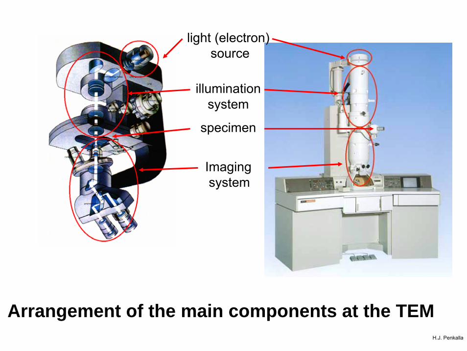
light source
illumination system
imaging system
specimen
Basic functions of an optical microscopeH.J. Penkalla
Imagingsystem
specimen
Arrangement of the main components at the TEM
illuminationsystem
light (electron)source
H.J. Penkalla


Electron Beam Sources: Thermal Emitter

Electron Beam Sources: Field-Emitter


Lens Aberrations:
Spherical and Chromatic Aberration

Specimen preparation: ion beam thinning
2.5 - 4.0 kV

Specimen preparation: electroytical jet thinning

Specimen preparation: ultramicrotomy

Specimen preparation: carbon replica

Gate-width 12,5 nm
A new era in nanoanalysis:

Design of a Focused Ion Beam Workstation FIB

FIB-nanolithography :FIM/TAP - Tips
Nanodevices
Magnetic memory
Test-masks
for EUV-
microscopy

FIB Preparation of TEM lamellae


Contrast enhancement by the use of the objectiveaperture
H.J. Penk

Structure Chemistry
Bonding

High Resolution Transmission Electron Microscopy

plane wave
Transmissionfunction
Fourier-Transformation
Fourier-Transformation
Diffractionpattern
real image
HRTEM

HRTEM:
Nb/Sapphire
Interfaces

Contrast Transfer: Incoherent Imaging System
Rayleigh Criterion
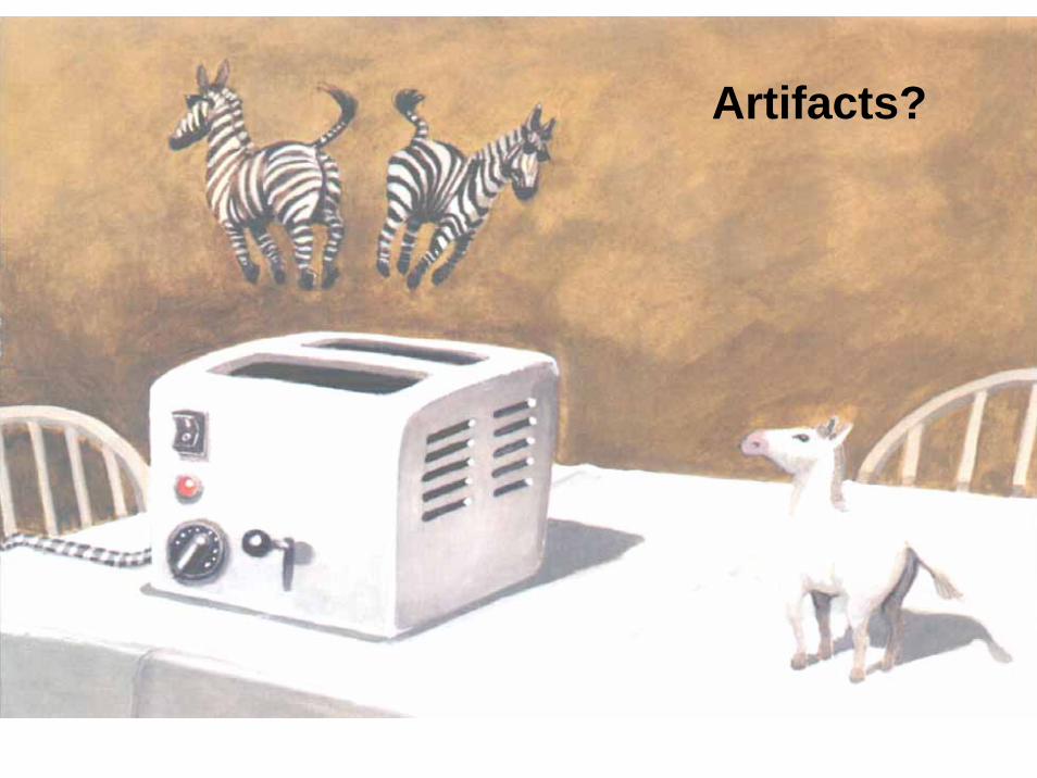
Artifacts?

Specimenphase shift of scattered wave: -π/2
phase shift by defocus: -π/2
Intensity contrast

Spherical Aberration
MagneticLens
GaussianImage Plane

Contrast Transfer Function (CTF)
Scherzer Focus, no damping

Contrast Transfer:
Real Imaging System

Spherical Aberration
MagneticLens
GaussianImage Plane
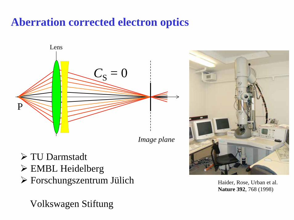
Lens
P
CS = 0
Image plane
Aberration corrected electron optics
TU DarmstadtEMBL HeidelbergForschungszentrum Jülich
Volkswagen Stiftung
Haider, Rose, Urban et al. Nature 392, 768 (1998)

Hexapole Cs-Corrector
(Rose, Haider)

Example: SrTiO3, calculated images
Structuremodel
withoutcorrector
Cs-corrector,Cs = + 40 µm
Cs-corrector, Cs = - 40 µm, changes in oxygen sublattice
Jia, Lentzen, Urban, Science 299 (2003)

Twin Boundaries inBaTiO3
Jia and Urban, Science 303 (2004)

CsxNb2.54W2.46O14
Focal-series reconstruction of the object exit-plane wave function
Phase image = projected potential for thin object
Th. Weirich
J. Barthel, A. Thust (ER-C)
G. Cox, H. Hibst(BASF)

aa
bb
averaged phase image+ p2gg symmetry correction
projected crystal structure
CsxNb2.54W2.46O14
Th. Weirich, J. Barthel, A. Thust (ER-C), G. Cox, H. Hibst (BASF)

Structure Chemistry
Bonding

Analytical TEM: Electron Intensity Distribution

Inelastic Scattering, low energy losses:
phonon and plasmon excitation
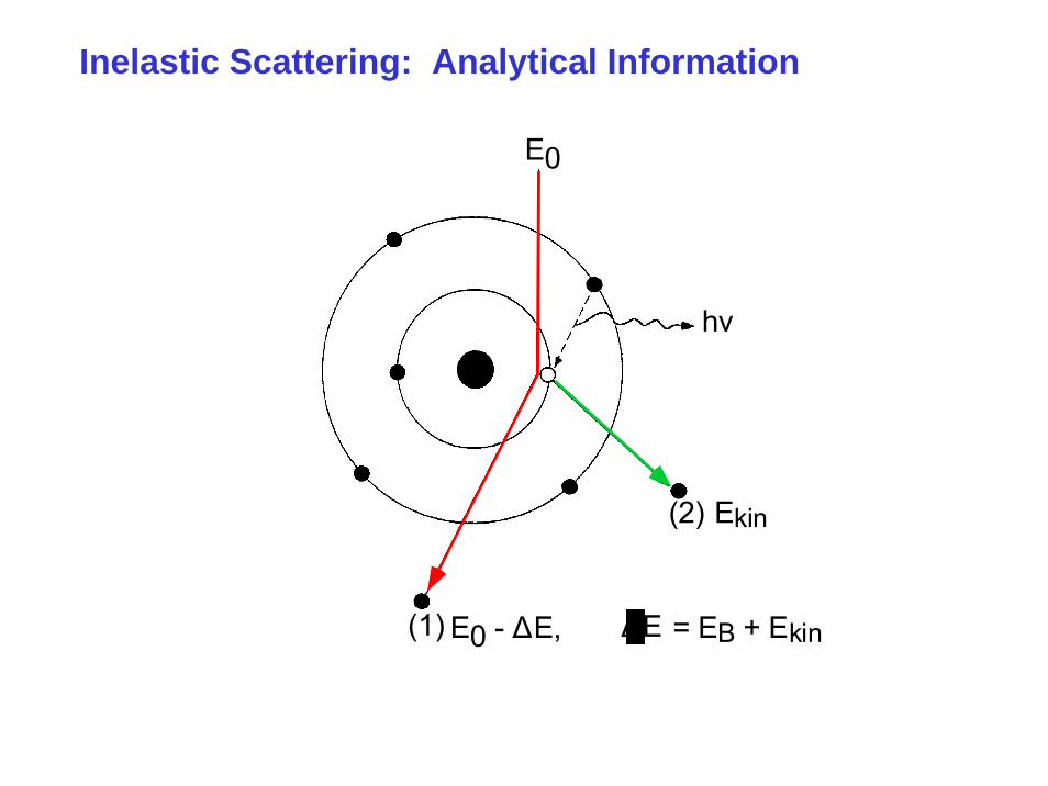
h ν
( 2 ) E k i n
( 1 ) E 0 - Δ E ,
D
= E B + E k i n
E 0
E Δ
Inelastic Scattering: Analytical Information


Schematical Energy Loss Spectrum
h ν
( 2 ) E k i n
( 1 ) E 0 - Δ E ,
D
= E B + E k i n
E 0
E Δ


B
Energy Loss Spectrometer(magnetic prism)

The Omega Energy Filter

CondensorSystem(KöhlerIllumination)AnalyticalObjective Lens
First ProjectorSystem
Imaging½-Spectrometer
SecondProjectorSystem
ViewingChamber
ElectronDetectorand Camera
Energy SelectingSlit
EucentricGoniometer
Cathode
Energy Filter
Specimen
ImagingΩ−Spectrometer
Energy selectingslit

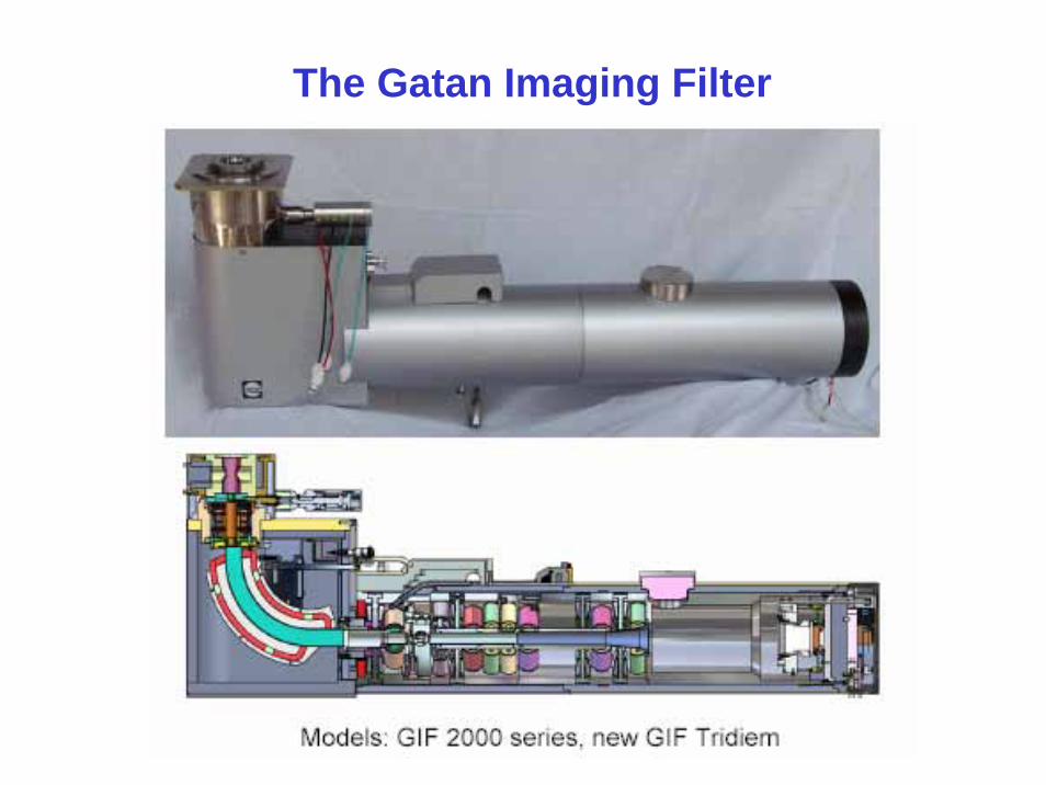
The Gatan Imaging Filter

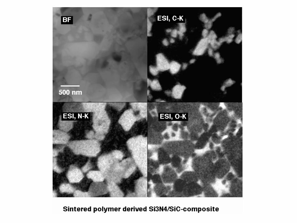
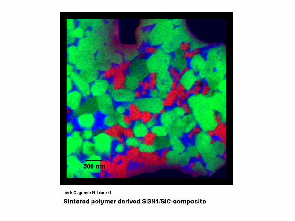
Elemental Distribution Images:
Three Window Technique