instrumentation and software architecture for a … · room has a surround sound audio system. the...
TRANSCRIPT

��������������������������������������������������������������������������1(8)� �������������������������������
��������������������������� ����!�"�#$��%�����&��
�
��������������'�(����������)�!������������*��+����������,-%����������������������
INSTRUMENTATION AND SOFTWARE ARCHITECTURE FOR A SMART ROOM
Antti Tikanmäki, Jaakko Suutala, Juha Röning Intelligent Systems Group
University of Oulu, Finland email:{sunday, jaska, jjr}@ee.oulu.fi
+35885532537, P.O. BOX 4500, 90014 University of Oulu, Finland
ABSTRACT
This paper presents the instrumentation and software architecture of a smart room. The smart room is a part of research on distributed intelligent services, and it provides a practical environment for the development of a distributed architecture. The smart room consists of resources such as sensors, different kinds of devices, and other kinds of computational and control and service resources that provide intelligent functionalities. The software architecture provides the possibility to easily control these distributed resources in the room, and it facilitates the creation of new and more complex functionalities for the system. The software architecture also provides the possibility to easily add new resources to the system. Keywords: Smart room, Property Service, Distributed software architecture.
1. INTRODUCTION
The goal of intelligent systems research is to create environments containing distributed devices that can operate as a one system and ease human everyday life. Many applications already exist, and they are target to E.G. homes with automatic functionalities [1], meeting rooms with an intelligent presentation system [2], classrooms [3] and intelligent surveillance systems [4]. Similar applications can also be built in different kinds of environments, like hospitals and public places.
There are several kinds of ways to connect devices in a distributed system. There are different kinds of commercially available devices and communication networks for creating a network for system like Ethernet, LonWorks, CAN and X10 [5]. Most of these also provide several kinds of concepts and devices to be used in building the systems. The choice between functionality and a lack of expandability must be considered as the fixed features of a commercial solution may not be improvable. The room design is usually a compromise between the price and the features of the system.
We have built our smart room to act as a future intelligent home, containing several intelligent functionalities. The room can be divided into several
rooms of an intelligent home using moveable walls, shown in Figure 1. The Figure also shows placements of several devices that provide services for the distributed system of the intelligent room. The smart room was built using several kinds of commonly available devices, and they are controlled mainly through an Ethernet. Ethernet is an easy choice, as the laboratory already contains a comprehensive network. In addition, Wireless LAN is, which is used in mobile robots, is also available. The room also has an X10 network for controlling lights in the room. X10 uses power lines to communicate between devices. The devices are introduced in more detailed in Chapter 2.
As the set of devices is quite large, using them manually is complex or takes time. Different devices contain different kinds of functionalities, and they are controlled in different ways. A major problem in using software-driven distributed services is in designing and maintaining interfaces for these resources. When a new kind of resource is added, updates might be needed across the system. In addition to adding new resources to the system, the functionality of a resource may increase. This usually requires changes in the interface. In our solution, a very simple interface for the service is used, and the functionalities of the resource are presented with the properties of the service. The properties hide the actual implementation a behind set of properties. The set of properties can also change dynamically during the operation, providing the possibility to expand the system during operation. The use of property service architecture for the smart room is introduced in Chapter 3.
To be able to create intelligent functionalities for the room, several control services have been developed. The simplest way to do this is by connecting events and actions in the room. For example, when somebody enters the room (an event from a sensor), lights are turned on (action). The rules are specified by a human. To gain more complex functionalities, state machines have been used to create different kinds of conditional functionalities for the room. Both are introduced more closely in Chapter 3.2.
One important task for the room is to know the locations and identities of people, as well as to model their behavior. In the first phase, we have concentrated on modeling person identification, which is based on

��������������������������������������������������������������������������2(8)� �������������������������������
��������������������������� ����!�"�#$��%�����&��
�
��������������'�(����������)�!������������*��+����������,-%����������������������
footstep profiles obtained from pressure-sensitive EMFI floor sensors [6]. The floor provides a natural and transparent way to model the identity of a walking person
by using the behavior characteristics of footstep biometrics. The phases of footstep detection and identification are explained more closely in Chapter 4.
Figure 1, Devices in an intelligent room
2. INSTRUMENTATION The smart room contains several devices, sensors and actuators, which are used to create the functionality of the room. Several cameras have been mounted on the ceiling of the room, and two rotating cameras that can pan, tilt and zoom are located on opposite sides of the room. The room has a surround sound audio system. The room also has two video projectors and several video sources, like a DVD player, a VCR, and several computers. Each video source can be connected to a video projector using a video multiplexer. To be able to build an intelligent system that can use all these devices and other resources in the room, a communication and a way to connect them to the distributed software are needed. Different devices contain different kinds of functionalities, and they are controlled in different ways. For example, an amplifier can be controlled through a serial port, and a light system by using the X10 protocol [5]. Each device provides a smart service for the distributed system. These smart services provide an interface to the device and several higher level functionalities that ease the usage of the device. In addition to just providing raw data from a sensor, it is reasonable to do some data processing on a PC or embedded system to which the sensor is connected. To be
able to use all the functionalities, rather complex interfaces are usually needed and updating the interface becomes a difficult task as the program improves. 2.1. Controlling the devices Most of the devices can be used with an RS232 controller. Each of these devices is connected to a PC located in the room. Each PC communicates with the others using a 100 Megabit Ethernet. In addition to providing device services for the system, they might also contain control services for creating intelligent functionality for the room. The rotating cameras (Sony EVI-D30) can be controlled using Sony’s Visca protocol. The video projector, amplifier and multiplexers have their own serial port protocol. Each protocol has been implemented using Java language to give high portability to the services. Therefore these services can be run on several operating systems as well as on several devices, like PCs and PDA devices that support Java. 2.2. Lights The light system of the room uses X10 protocol devices, and these devices communicate through the power line. To access the devices, a control box for X10 is connected to a PC through a serial port. The main reason for choosing X10 is that it is a rather cheap system,

��������������������������������������������������������������������������3(8)� �������������������������������
��������������������������� ����!�"�#$��%�����&���
��������������'�(����������)�!������������*��+����������,-%����������������������
providing the possibility to attach several simple devices like lights and sensors via the power line. However, the protocol is very limited and the data transferring rate on the power line using the X10 protocol is very slow. 2.3. EMFI Floor sensor One of the main sensors for detecting events in the room's environment is the EMFI floor sensors. The floor of the room (100 m2) is covered with 64 pieces of 30 cm wide and 10 m long EMFI sensors [6]. These sensors are placed under the floor material (see Figure 2.). All the sensors are connected to a 64 channel A/D converter card on a PC. This grid provides event information on pressure changes on the surface of the floor, like human footsteps and other kind of events like human falling down. The location of an event can be localized by combining information from the crossing stripes. To process the data from the floor sensors, the room has an IBM Blade server computer that provides refined information on actions on the floor sensor.
Figure 2, Sensor strips under the floor
2.4. Robots One important group of devices in the room is robots. Several kinds of robots are available to be used to create functionalities for the room. A Fanuc manipulator and different kinds of mobile robots can be used through distributed software and the use of a flexible architecture provides the possibility to use different kinds of robots to perform the same tasks in the room. The robotic part of the research has been described previously on [7], [8], [9] and [10]. The robots are an important part of our intelligent home system.
3. PROPERTY SERVICE ARCHITECTURE
To be able to use all the devices in the room, each of them needs an interface so that it can be used as a part of the distributed system. The set of different kinds of features and functionalities as well as the different communication channels pose a great challenge. In our
solution, the interface is the same for all the devices and it does not need to be changed even when new features are added. To gain access to different resources in the environment, we have used our Property Service architecture.
On previous work, Property Service Architecture has been used successfully for remote operation of mobile robots [7], multi-robot cooperation [9], remote operation of a swarm of robots [9] and creating a modular robots interface [10]. In this work, the same architecture was used to employ the resources in the smart room and to create intelligent functionalities. In addition to device resources, several other services have been developed. For example the State Machine Property Service [8] can be used to build complex state machines for higher level control of services. 3.1. The interface
The interface contains only two methods, "set" and "get", for getting and setting the properties of distributed devices or services. Properties are features or functionalities that a service provides. Property Service can be implemented over different protocols and communication media. Currently it has been implemented on TCP/IP sockets, CORBA, ZeroC ICE and a serial port. Each service provides properties related to features and the smart functionality of a device. For example, a light has a property for brightness level and a camera has a property for orientation and for a captured image. In addition to direct features of devices, many services provide additional properties related to the functionality of the device, like a smart operation or preset programs. The service also has a property called “properties”, which lists current properties of the service. The content of this property can be changed during runtime, which provide the possibility to change or expand the functionalities of the service during operation. 3.2. Standard properties The property service architecture defines several suggestions for naming the properties, which eases the implementation of new properties. When different devices that are still of the same type with several similarities contain a standard set of properties, it is easiest to replace the device with another kind of device. For example, all cameras have a property for image data, so different kinds of cameras can be used with the same program. Table 1 shows examples of some properties that the “rotating camera”-service has. In this example, the camera provides the properties for physical movement of the camera. By setting the position property, the remote client can set the orientation (and location, if it can be adjusted) of the camera. By getting the “position” property the client can request the current position of the camera. The “targets/list” property returns targets that the camera has detected in the field of view. As new methods

��������������������������������������������������������������������������4(8)� �������������������������������
��������������������������� ����!�"�#$��%�����&���
��������������'�(����������)�!������������*��+����������,-%����������������������
for visual processing of image data are added to the service, this property call returns more information from the camera view. The “behaviors/track” property is used for the automatic tracking functionality of the camera. By setting a description of the target, and enabling the behavior, the camera starts to automatically track the requested objects. Name Type Explanation position vector Current position of
the camera, all orientations in the same vector
zoom number Zooming value
data image Image captured with the camera
behaviors/track marker Tracking functionality of the camera, the parameter is a description of the target object
behaviors/track/enable 0 or 1 To activate the behavior.
targets/list list of markers
List of target objects the camera can detect on the field of view.
Table 1, Examples of properties of a Pan Tilt camera In many cases, especially when the transfer rate of a communication channel is limited, it is reasonable to transfer refined information instead of raw data, and higher level commands instead continuous control commands. In the mobile robot case, it is more reasonable to transfer the target location instead of continuously transferring driving commands. A good example of a service providing several kinds of refined data is the EMFI floor sensor service, introduced more closely in Chapter 4. 3.3. Implementing the services The property service architecture contains software libraries for several platforms and languages that ease the implementation of the software. The simplest way to implement a new service in the distributed system is by inheriting it from a base class in an available library, replacing the “set” and “get” methods. The Property Service library provides several available methods to parse property names and convert XML descriptions to and from several classes. This includes different kind of numbers, vectors and lists, as well as images, sound samples, etc. The property service specification defines a small set of preferred data types and property naming that eases the design of a set of properties.
The library also contains several tools developed to ease implementation. One of these is the Java Class Property Service that automatically creates connections to a Java class or several Java classes. This facilitates the reuse of previously built control classes. The programmer must only define the set and get methods of the class and Class Service parser automatically creates connections between the property names and the method calls of the class. 3.4. Grouping services Another new service is the Grouping Property Service that has been used to combine several services in the room into one Property Service. Using a Grouping Property Service is a sort of combination of centralized and decentralized systems where each service communicates and can be used separately, but their cooperative functionality has been attached to a Group Property Service. In the Grouping Property Service, the properties of each attached sub service are shown in a list of properties of the Grouping Property Service, and remote client can use them without actually connecting to the real service. The principle is shown in Figure 3. Several security functionalities can be included in the Grouping Property Service by, for example, limiting access to some properties from remote clients.
Figure 3, Example of calling a sub-property service. 3.5 Service for a smart room The Grouping Property Service has been used to group all the services in the room into one Property Service, called Intelligent Room Service. This service provides access to each service connected to the service. The Intelligent Room Service also provides several properties related to the current functionalities of the room’s distributed system. For example, a “behavior/surveillance” property can be used for accessing surveillance functionality of the room. The main advantage of this is that when new resources are added to the room, the properties related to the functionality remain the same. For example, the room contains three cameras and a surveillance functionality that provides the best view of events in the room. The user can activate and request information related to surveillance using property in the intelligent room service. When a new camera is attached to the system, it connects to the room service and provides an additional
��������������������������������������������������������������������������5(8)� �������������������������������
��������������������������� ����!�"�#$��%�����&���
��������������'�(����������)�!������������*��+����������,-%����������������������
camera view to the room. The surveillance functionality takes the camera as part of the functionality without the user needing to make changes in the control application. The usefulness of this kind of feature becomes clearer when a new, different kind of sensor that can take part in surveillance is attached to the system.
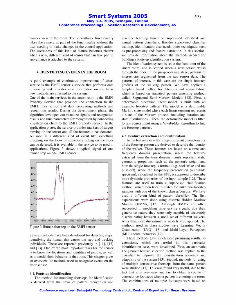
4. IDENTIFYING EVENTS IN THE ROOM A good example of continuous improvement of smart service is the EMFI sensor’s service that performs data processing and provides new information on events as new methods are attached to the system. One of the main services in the smart room is the EMFI Property Service that provides the connection to the EMFI floor sensor and data processing methods and recognition results. During the development phase, the algorithm developer can visualize signals and recognition results and tune parameters for recognition by connecting visualization client to the EMFI property service. In the application phase, the service provides markers of targets moving on the sensor and all the features it has detected. As soon as a different kind of event like something dropping on the floor or somebody falling on the floor can be detected, it is available in the service to be used in applications. Figure 3 shows a typical signal of one human step on one EMFI sensor.
Figure 3 Human footstep on the EMFI sensor Several methods have been developed for detecting steps, identifying the human that causes the step and tracking individuals. These are reported previously in [11], [12] and [13]. One of the most important tasks for the sensor is to know the locations and identities of people, as well as to model their behavior in the room. This chapter gives an overview for methods used to recognize events on the floor sensor. 4.1. Footstep identification
The method for modeling footsteps for identification is derived from the areas of pattern recognition and
machine learning based on supervised statistical and neural pattern classifiers. Besides supervised classifier training, identification also needs other techniques, such as pre-processing and feature extraction. In this section, we provide information about the methods needed for building a footstep identification system.
The identification system is set at the front door of the smart room, and is started when a new person walks through the door. In the pre-processing stage, patterns of interest are segmented from the raw sensor data. The patterns of interest, in this case are the single footstep profiles of the walking person. We have applied a template based method for detection and segmentation, which is based on statistical pattern matching method, called Segmental Semi-Markov Models [12]. First, a deformable piecewise linear model is built with an example footstep pattern. The model is a deformable Markov state model where each linear segment represents a state of the Markov process, including duration and state distributions. Then, the deformable model is fitted to raw sensor input using a Viterbi-like algorithm to find the footstep patterns.
4.2. Feature extraction and identification
In the feature extraction stage, different characteristics of the footstep pattern are derived to describe the identity of the walker. These features are based on a time and frequency domain presentation, where the features extracted from the time domain mainly represent static geometric properties, such as the person's weight and how the single footstep is formed (e.g. heel strike and toe push-off), while the frequency presentation (amplitude spectrum), calculated by the FFT, is supposed to describe more dynamic properties of the input sample [12]. These features are used to train a supervised classification method, which then tries to match the unknown footstep samples with one of the known classes/persons. We have used a different kind of pattern classifier. The first experiments were done using discrete Hidden Markov Models (HMMs) [12]. Although HMMs are often succeeded in modeling time-varying signals, due their generative nature they were only capable of accurately discriminating between a small set of different walkers. After that, more discriminative models were applied. The methods used in these studies were Learning Vector Quantization (LVQ) [13] and Multi-Layer Perceptron (MLP) neural networks [12].
These methods gave much more promising results, so extensions, which are useful in this particular identification case, were developed. First, an automatic LVQ-based feature selection method was applied to the classifier to improve the identification accuracy and adaptivity of the system [13]. Second, methods for using of multiple consecutive footsteps from the same person were studied [13]. This was found very useful, due to the fact that it is very easy and fast to obtain a couple of consecutive footsteps when a person is entering the room. The combinations of multiple footsteps were based on
��������������������������������������������������������������������������6(8)� �������������������������������
��������������������������� ����!�"�#$��%�����&���
��������������'�(����������)�!������������*��+����������,-%����������������������
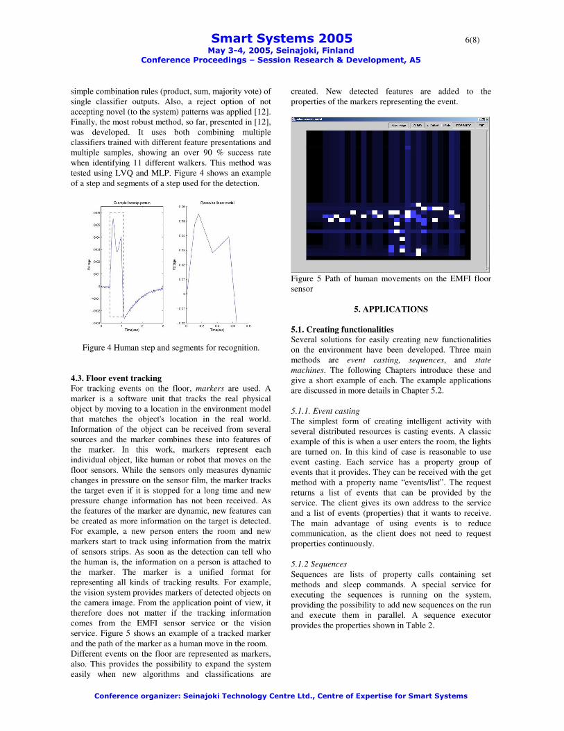
simple combination rules (product, sum, majority vote) of single classifier outputs. Also, a reject option of not accepting novel (to the system) patterns was applied [12]. Finally, the most robust method, so far, presented in [12], was developed. It uses both combining multiple classifiers trained with different feature presentations and multiple samples, showing an over 90 % success rate when identifying 11 different walkers. This method was tested using LVQ and MLP. Figure 4 shows an example of a step and segments of a step used for the detection.
Figure 4 Human step and segments for recognition.
4.3. Floor event tracking For tracking events on the floor, markers are used. A marker is a software unit that tracks the real physical object by moving to a location in the environment model that matches the object's location in the real world. Information of the object can be received from several sources and the marker combines these into features of the marker. In this work, markers represent each individual object, like human or robot that moves on the floor sensors. While the sensors only measures dynamic changes in pressure on the sensor film, the marker tracks the target even if it is stopped for a long time and new pressure change information has not been received. As the features of the marker are dynamic, new features can be created as more information on the target is detected. For example, a new person enters the room and new markers start to track using information from the matrix of sensors strips. As soon as the detection can tell who the human is, the information on a person is attached to the marker. The marker is a unified format for representing all kinds of tracking results. For example, the vision system provides markers of detected objects on the camera image. From the application point of view, it therefore does not matter if the tracking information comes from the EMFI sensor service or the vision service. Figure 5 shows an example of a tracked marker and the path of the marker as a human move in the room. Different events on the floor are represented as markers, also. This provides the possibility to expand the system easily when new algorithms and classifications are
created. New detected features are added to the properties of the markers representing the event.
Figure 5 Path of human movements on the EMFI floor sensor
5. APPLICATIONS 5.1. Creating functionalities Several solutions for easily creating new functionalities on the environment have been developed. Three main methods are event casting, sequences, and state machines. The following Chapters introduce these and give a short example of each. The example applications are discussed in more details in Chapter 5.2. 5.1.1. Event casting The simplest form of creating intelligent activity with several distributed resources is casting events. A classic example of this is when a user enters the room, the lights are turned on. In this kind of case is reasonable to use event casting. Each service has a property group of events that it provides. They can be received with the get method with a property name “events/list”. The request returns a list of events that can be provided by the service. The client gives its own address to the service and a list of events (properties) that it wants to receive. The main advantage of using events is to reduce communication, as the client does not need to request properties continuously. 5.1.2 Sequences Sequences are lists of property calls containing set methods and sleep commands. A special service for executing the sequences is running on the system, providing the possibility to add new sequences on the run and execute them in parallel. A sequence executor provides the properties shown in Table 2.

��������������������������������������������������������������������������7(8)� �������������������������������
��������������������������� ����!�"�#$��%�����&���
��������������'�(����������)�!������������*��+����������,-%����������������������
Name Type Explanation sequences group All sequences
are under this property. They are accessed using the “name” property
sequences/”name” string Sequence called “name”
sequences/”name”/enable 0 or 1 Enables or disables the sequence
Table 2. Properties of Sequence Execution Service By setting the “sequences/mysequence” property with the value of sequence, a remote service can add a new sequence to the executor. By setting an empty value to sequence with same name, the sequence is automatically removed from the service. The sequence can also have a “loop N” parameter where N defines how many times the sequence will be looped. 5.1.3 State Machines When more complex control is needed and sequences cannot perform the functionality, State Machines are used. State Machines contain conditional translations that can perform many of new features. In comparison with conventional state machines, our state machine removes the limitations of parallelism, and the execution can run on many parallel states. State machines are described more closely in [8]. The fields (like “condition” and “action”) in the state machine contain script language, and the script is used to create more complex functionality instead of creating them using states and transitions. Good examples of this are the usage of arithmetic comparisons between values of properties and creating loops using script language. On current release, PHP as a script language or LUA can be used to create the content of state machines. State machines are written in RDF-XML format, and the same format is used when state machines are transferred between services. The execution of a state machine can be “stand alone”, providing its own service for execution or it can be a part of another service, providing functionality to the service. 5.2 Applications Several applications have already been created to show the functionality and cooperation of services. The following briefly introduces them and explains what
services take part in functionality. Each application and functionality of the distributed system can be enabled, configured and monitored using the properties of the Intelligent Room Service. 5.2.1 Surveillance In first application, the system is used for room surveillance. The EMFI service sends information on movements on the floor, and two rotating cameras are turned in the direction of movement. The main advantage in comparison with visual tracking systems is that no image processing is required to find movement events in the room. Obviously the system can expand to using both detection methods for the same functionality. If some places on the room are not visible to static cameras, a mobile robot with a camera can be requested to move to an event position and take a picture of the target. 5.2.2. Intelligent home In the second application, the services are used to create automatic home functionalities like room lighting control and human service robots. The EMFI service provides information on locations and detection of targets moving in the room. The light in each segment of the room (see Figure 1.) is turned on as the human moves there. When the human stops, an EMFI floor sensor does not detect any movement, but a tracking marker stays in the location where the last movement happened. In a more complex version, the first and second applications are combined and lights turn on in the area of movement and cameras turn in the direction of an event. 5.2.3 Presentation room One use for the smart room is as a presentation room for visitors. As the room and devices are used for several purposes, the configurations of the video multiplexer’s, amplifier’s and video projector's inputs are usually wrong for showing the presentation from a computer. As all the needed devices can be controlled using property services, a simple sequence of property calls can be used to set all the devices into the right mode for presentation or other use. Similar sequences are used to set the room into another mode related to usage of the room. As the sequences are in human readable form, they are easily modifiable into a suitable form.
6. CONCLUSION
As a result, the smart room provides good instruments for researching an intelligent home. To solve the problem of creating interfaces for distributed devices in the intelligent room, a Property Service Architecture has been proposed. By using the Property Service architecture, new devices are easy to attach to the system and they are easily in use. One of main advantages of the Property Service is also the reusability of developed methods.

��������������������������������������������������������������������������8(8)� �������������������������������
��������������������������� ����!�"�#$��%�����&���
��������������'�(����������)�!������������*��+����������,-%����������������������
The results of the EMFI data processing method are also easily used in several other kinds of classification of signals. The development of sensor data processing methods for EMFI sensor signals provides great advantages in also building several other kinds of intelligent sensor systems that utilize detection of signal shapes. Each step of the detection procedure is easily reached through an expandable property service interface, and parameters and learning can be controlled through an easy-to-use interface, and remotely. The unified form of markers used to represent detected targets of several kinds of sensor data processing resources, like camera vision and EMFI sensor data, provides the possibility to combine the information from various sources to facilitate the operation of a distributed system.
7. ACKNOWLEDGEMENTS
This work has been partly funded by the Academy of Finland.
8. REFERENCES [1] Kidd, Cory D., Robert J. Orr, Gregory D. Abowd,
Christopher G. Atkeson, Irfan A. Essa, Blair MacIntyre, Elizabeth Mynatt, Thad E. Starner and Wendy Newstetter. "The Aware Home: A Living Laboratory for Ubiquitous Computing Research", CoBuild'99. 1999
[2] A. Waibel, T. Schultz, M. Bett, M. M. Denecke, R. Malkin, I. Rogina, R. Stiefelhagen, J. Yang, “Smart: The Smart Meeting Room Task at ISLgnition”, ICASSP, 2003.
[3] Yanhua Mao, Weikai Xie, Yuanchun Shi, Guangyou Xu, Xin Xiang, "Building the Software Infrastructure for Smart Classroom: From Open Agent Architecture (OAA) to Smart Platform", PCM2002, 2002
[4] M. Valera, S.A. Velastin. "An approach for designing a real-time intelligent distributed surveillance system". Intelligent distributed surveillance systems symposium organised by the IEE Visual Information Engineering Professional Network. 26th February 2003, IEE Savoy Place, London.
[5] Introduction to X10 protocol: http://www.smarthome.com/about_x10.html (visited 29.03.2005)
[6] EMFi sensor provider, http://www.emfit.com (visited 29.03.2005)
[7] Antti Tikanmäki, Juha Röning and Jukka Riekki (2003) Remote operation of robotics systems using WLAN- and CORBA based architecture, 2003 SPIE / Intelligent Robots and Computer Vision XXI, Oct 27 - 31, Rhode Island, Providence, RI USA
[8] Topi Mäenpää, Antti Tikanmäki, Jukka Riekki and Juha Röning (2004) A Distributed Architecture for Executing Complex Tasks with Multiple Robots, IEEE 2004 ICRA, International Conference on Robotics and Automation,Apr 26 - May 1, New Orleans, LA, USA
[9] Antti Tikanmäki, Juha Röning (2004) Advanced Remote Operation of swarms of Robots, 2004 SPIE / Intelligent Robots and Computer Vision XXII, Philadelphia, USA
[10] Antti Tikanmäki, Tero Vallius, Juha Röning (2004) Qutie - Modular methods for building complex mechatronic systems, ICMA - International Conference on Machine Automation, Nov. 24.-26., Osaka, Japan
[11] Koho K., Suutala J., Seppänen T., Röning J. (2004) Footstep Pattern Matching from Pressure Signals Using Segmental Semi-Markov Models, 12th European Signal Processing Conference (EUSIPCO 2004), September 6-10, Vienna, Austria, pp. 1609-1612.
[12] Suutala J., Röning J. (2005) Combining classifiers with different footstep feature sets and multiple samples for person identification 30th IEEE International Conference on Acoustics, Speech, and Signal Processing (ICASSP05), March 18-23, Philadelphia, USA, (accepted).
[13] Suutala J., Röning J. (2004) Towards the Adaptive Identification of Walkers: Automated Feature Selection of Footsteps Using Distinction-Sensitive LVQ, International Workshop on Processing Sensory Information for Proactive Systems (PSIPS 2004), June 14-15, Oulu, Finland, pp. 61-67.
[14] Suutala J. (2004) Methods for Person Identification from Pressure Signal of Walking Steps, M.Sc. Thesis, University of Oulu, Department of Electrical and Information Engineering, Oulu, Finland, 90 p., (in Finnish).