instructor: erol sahin y86 instruction set architecture – seq processor ceng331: introduction to...
TRANSCRIPT

Instructor:
Erol Sahin
Y86 Instruction Set Architecture – SEQ processorCENG331: Introduction to Computer Systems8th Lecture
Acknowledgement: Most of the slides are adapted from the ones prepared by R.E. Bryant, D.R. O’Hallaron of Carnegie-Mellon Univ.

– 2 –
Instruction Set ArchitectureAssembly Language View
Processor state Registers, memory, …
Instructionsaddl, movl, leal, … How instructions are encoded as
bytes
Layer of Abstraction Above: how to program machine
Processor executes instructions in a sequence
Below: what needs to be built Use variety of tricks to make it run
fast E.g., execute multiple instructions
simultaneously
ISA
Compiler OS
CPUDesign
CircuitDesign
ChipLayout
ApplicationProgram
– 3 –
%eax%ecx%edx%ebx
%esi%edi%esp%ebp
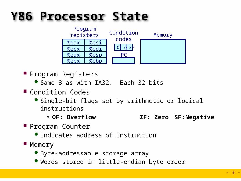
Y86 Processor State
Program Registers Same 8 as with IA32. Each 32 bits
Condition Codes Single-bit flags set by arithmetic or logical instructions
» OF: Overflow ZF: Zero SF:Negative Program Counter
Indicates address of instruction Memory
Byte-addressable storage array Words stored in little-endian byte order
Program registers Condition
codes
PC
Memory
OF ZF SF

– 4 –
Y86 Instructions
Format 1--6 bytes of information read from memory
Can determine instruction length from first byte Not as many instruction types, and simpler encoding than with IA32
Each accesses and modifies some part(s) of the program state

– 5 –
Encoding RegistersEach register has 4-bit ID
Same encoding as in IA32
Register ID 8 indicates “no register” Will use this in our hardware design in multiple places
%eax%ecx%edx%ebx
%esi%edi%esp%ebp
0123
6745
– 6 –
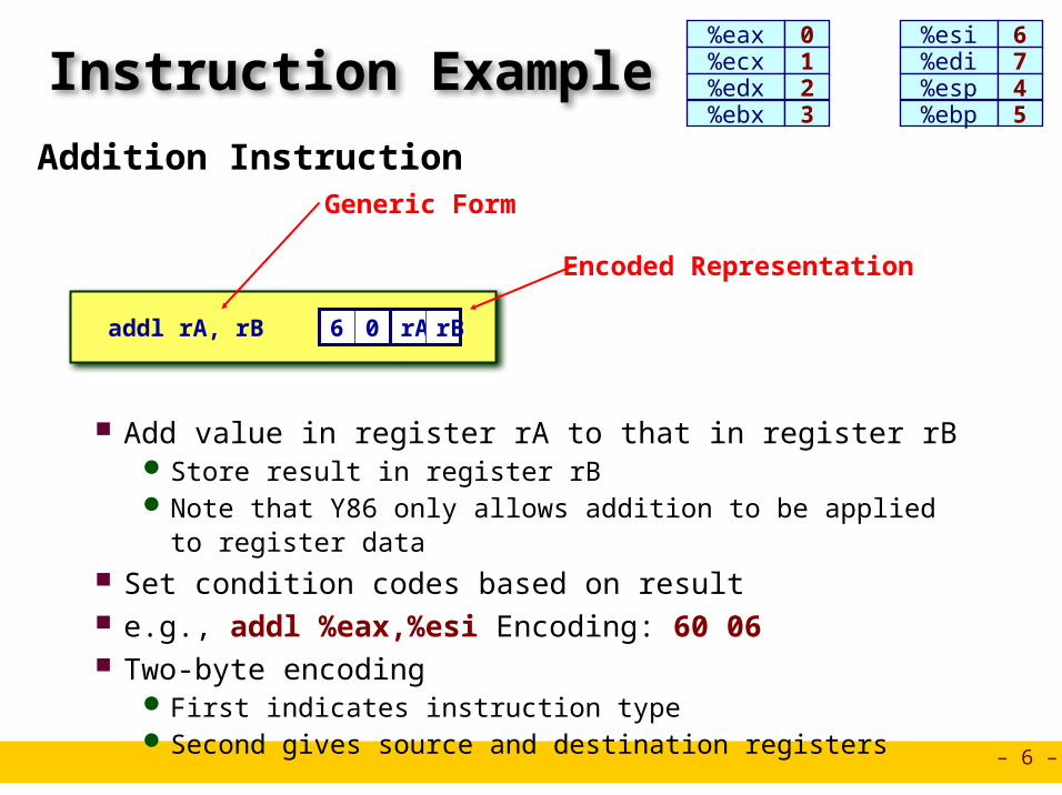
Instruction ExampleAddition Instruction
Add value in register rA to that in register rB Store result in register rB Note that Y86 only allows addition to be applied to register data
Set condition codes based on result e.g., addl %eax,%esi Encoding: 60 06 Two-byte encoding
First indicates instruction type Second gives source and destination registers
addl rA, rB 6 0 rA rB
Encoded Representation
Generic Form
%eax%ecx%edx%ebx
%esi%edi%esp%ebp
0123
6745

– 7 –
Arithmetic and Logical Operations Refer to generically as “OPl” Encodings differ only by
“function code” Low-order 4 bytes in first
instruction word Set condition codes as side
effect
addl rA, rB 6 0 rA rB
subl rA, rB 6 1 rA rB
andl rA, rB 6 2 rA rB
xorl rA, rB 6 3 rA rB
Add
Subtract (rA from rB)
And
Exclusive-Or
Instruction Code Function Code
– 8 –
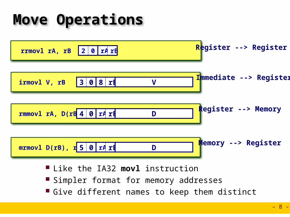
Move Operations
Like the IA32 movl instruction Simpler format for memory addresses Give different names to keep them distinct
rrmovl rA, rB 2 0 rA rB Register --> Register
Immediate --> Registerirmovl V, rB 3 0 8 rB V
Register --> Memoryrmmovl rA, D(rB) 4 0 rA rB D
Memory --> Registermrmovl D(rB), rA 5 0 rA rB D
– 9 –
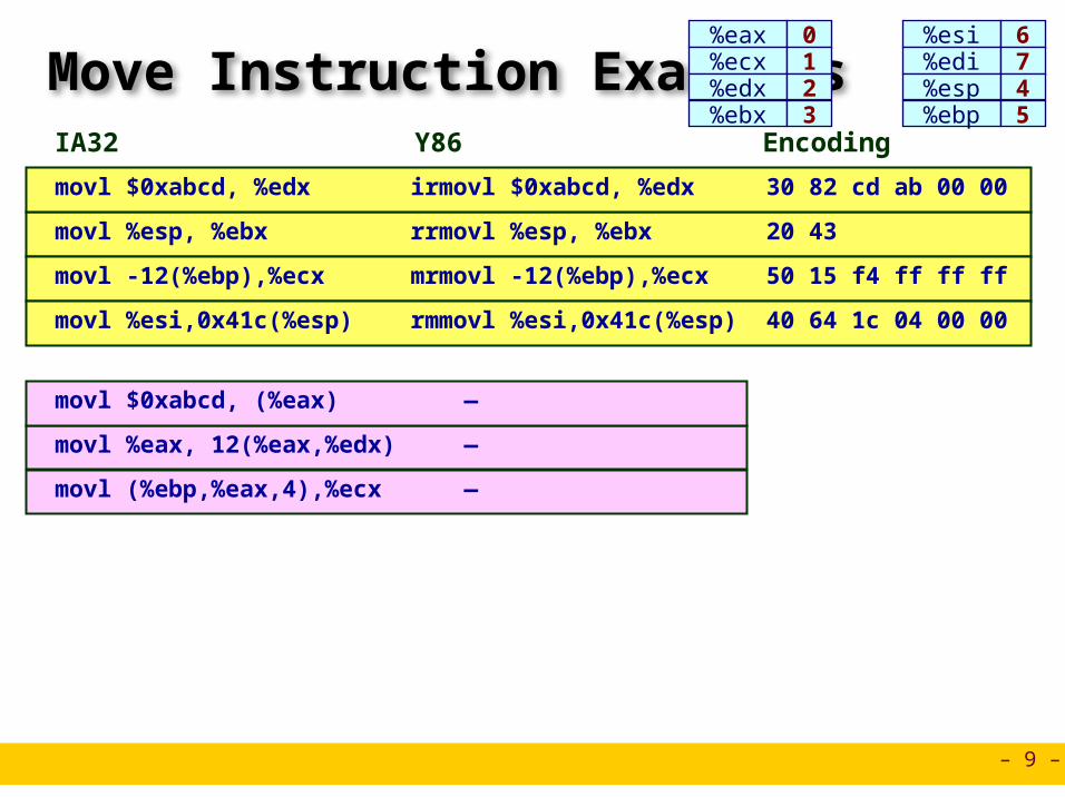
Move Instruction Examples
irmovl $0xabcd, %edx movl $0xabcd, %edx 30 82 cd ab 00 00
IA32 Y86 Encoding
rrmovl %esp, %ebx movl %esp, %ebx 20 43
mrmovl -12(%ebp),%ecxmovl -12(%ebp),%ecx 50 15 f4 ff ff ff
rmmovl %esi,0x41c(%esp)movl %esi,0x41c(%esp)
—movl $0xabcd, (%eax)
—movl %eax, 12(%eax,%edx)
—movl (%ebp,%eax,4),%ecx
40 64 1c 04 00 00
%eax%ecx%edx%ebx
%esi%edi%esp%ebp
0123
6745

– 10 –
Jump Instructions Refer to generically as “jXX” Encodings differ only by
“function code” Based on values of condition
codes Same as IA32 counterparts Encode full destination address
Unlike PC-relative addressing seen in IA32
jmp Dest 7 0
Jump Unconditionally
Dest
jle Dest 7 1
Jump When Less or Equal
Dest
jl Dest 7 2
Jump When Less
Dest
je Dest 7 3
Jump When Equal
Dest
jne Dest 7 4
Jump When Not Equal
Dest
jge Dest 7 5
Jump When Greater or Equal
Dest
jg Dest 7 6
Jump When Greater
Dest

– 11 –
Y86 Program Stack Region of memory holding program
data Used in Y86 (and IA32) for supporting
procedure calls Stack top indicated by %esp
Address of top stack element Stack grows toward lower addresses
Top element is at highest address in the stack
When pushing, must first decrement stack pointer
When popping, increment stack pointer
%esp
•••
IncreasingAddresses
Stack “Top”
Stack “Bottom”
– 12 –
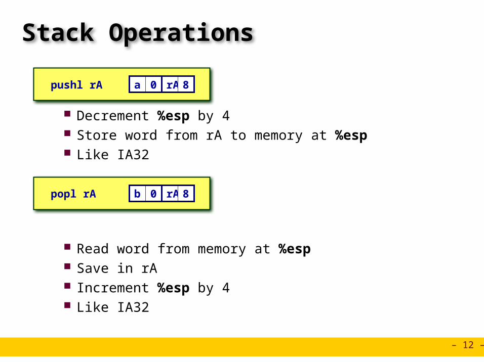
Stack Operations
Decrement %esp by 4 Store word from rA to memory at %esp Like IA32
Read word from memory at %esp Save in rA Increment %esp by 4 Like IA32
pushl rA a 0 rA 8
popl rA b 0 rA 8

– 13 –
Subroutine Call and Return
Push address of next instruction onto stack Start executing instructions at Dest Like IA32
Pop value from stack Use as address for next instruction Like IA32
call Dest 8 0 Dest
ret 9 0
– 14 –
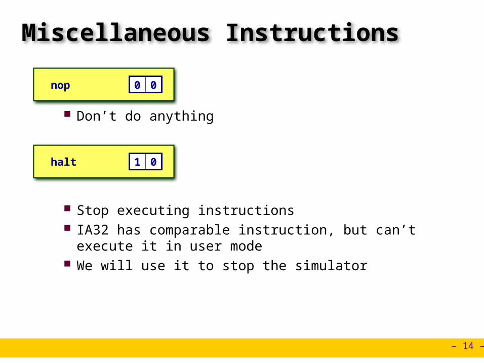
Miscellaneous Instructions
Don’t do anything
Stop executing instructions IA32 has comparable instruction, but can’t execute it in user
mode We will use it to stop the simulator
nop 0 0
halt 1 0

– 15 –
Y86 Code Generation Example
First Try Write typical array code
Compile with gcc -O2 -S
Problem Hard to do array indexing on Y86
Since don’t have scaled addressing modes
/* Find number of elements in null-terminated list */int len1(int a[]){ int len; for (len = 0; a[len]; len++)
; return len;}
L18:incl %eaxcmpl $0,(%edx,%eax,4)jne L18
– 16 –
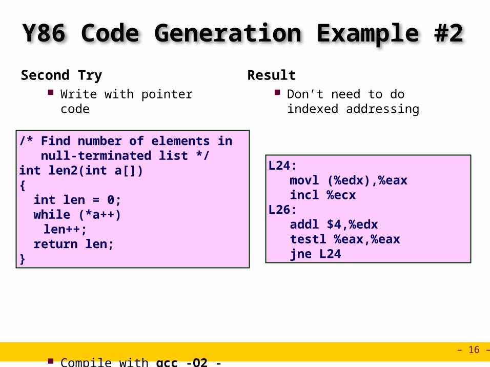
Y86 Code Generation Example #2
Second Try Write with pointer code
Compile with gcc -O2 -S
Result Don’t need to do indexed
addressing
/* Find number of elements in null-terminated list */int len2(int a[]){ int len = 0; while (*a++)
len++; return len;}
L24:movl (%edx),%eaxincl %ecx
L26:addl $4,%edxtestl %eax,%eaxjne L24

– 17 –
Y86 Code Generation Example #3
IA32 Code Setup
Y86 Code Setup
len2:pushl %ebpxorl %ecx,%ecxmovl %esp,%ebpmovl 8(%ebp),%edxmovl (%edx),%eaxjmp L26
len2:pushl %ebp # Save %ebpxorl %ecx,%ecx # len = 0rrmovl %esp,%ebp # Set framemrmovl 8(%ebp),%edx# Get amrmovl (%edx),%eax # Get *ajmp L26 # Goto entry

– 18 –
Y86 Code Generation Example #4
IA32 Code Loop + Finish
Y86 Code Loop + Finish
L24:movl (%edx),%eaxincl %ecx
L26:addl $4,%edx
testl %eax,%eaxjne L24movl %ebp,%espmovl %ecx,%eaxpopl %ebpret
L24:mrmovl (%edx),%eax # Get *airmovl $1,%esiaddl %esi,%ecx # len++
L26: # Entry:irmovl $4,%esiaddl %esi,%edx # a++andl %eax,%eax # *a == 0?jne L24 # No--Looprrmovl %ebp,%esp # Poprrmovl %ecx,%eax # Rtn lenpopl %ebpret

– 19 –
Y86 Program Structure
Program starts at address 0
Must set up stack Make sure don’t
overwrite code! Must initialize data Can use symbolic
names
irmovl Stack,%esp # Set up stackrrmovl %esp,%ebp # Set up frameirmovl List,%edxpushl %edx # Push argumentcall len2 # Call Functionhalt # Halt
.align 4List: # List of elements
.long 5043
.long 6125
.long 7395
.long 0
# Functionlen2:
. . .
# Allocate space for stack.pos 0x100Stack:
– 20 –
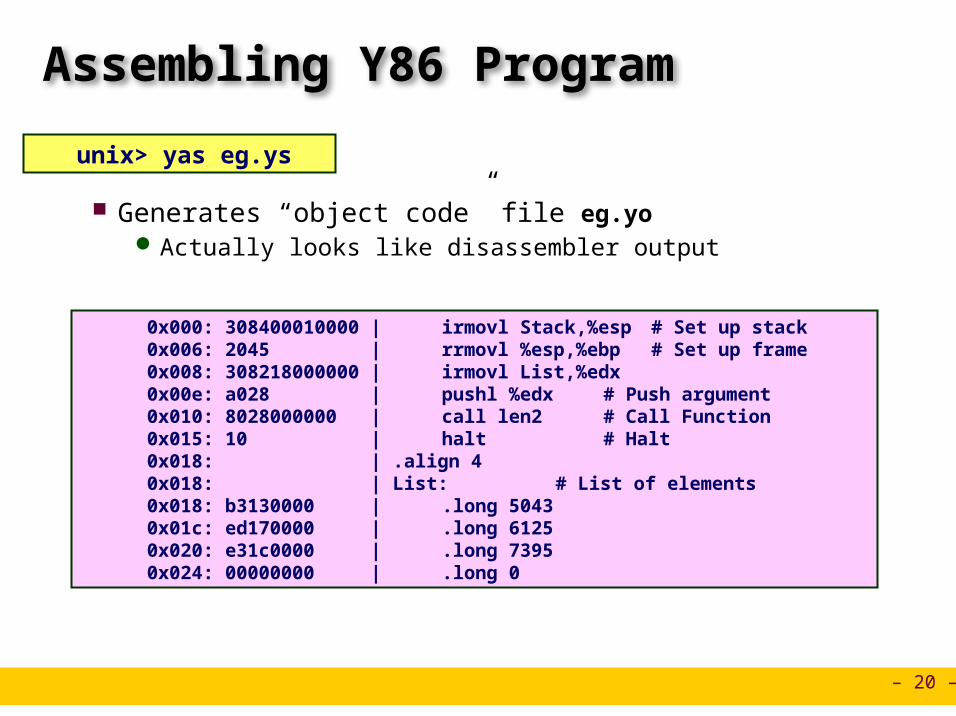
Assembling Y86 Program
Generates “object code” file eg.yo Actually looks like disassembler output
unix> yas eg.ys
0x000: 308400010000 | irmovl Stack,%esp # Set up stack 0x006: 2045 | rrmovl %esp,%ebp # Set up frame 0x008: 308218000000 | irmovl List,%edx 0x00e: a028 | pushl %edx # Push argument 0x010: 8028000000 | call len2 # Call Function 0x015: 10 | halt # Halt 0x018: | .align 4 0x018: | List: # List of elements 0x018: b3130000 | .long 5043 0x01c: ed170000 | .long 6125 0x020: e31c0000 | .long 7395 0x024: 00000000 | .long 0

– 21 –
Simulating Y86 Program
Instruction set simulator Computes effect of each instruction on processor state Prints changes in state from original
unix> yis eg.yo
Stopped in 41 steps at PC = 0x16. Exception 'HLT', CC Z=1 S=0 O=0Changes to registers:%eax: 0x00000000 0x00000003%ecx: 0x00000000 0x00000003%edx: 0x00000000 0x00000028%esp: 0x00000000 0x000000fc%ebp: 0x00000000 0x00000100%esi: 0x00000000 0x00000004
Changes to memory:0x00f4: 0x00000000 0x000001000x00f8: 0x00000000 0x000000150x00fc: 0x00000000 0x00000018
Instructor:
Erol Sahin
CISC versus RISC CENG331: Introduction to Computer Systems8th Lecture
Acknowledgement: Most of the slides are adapted from the ones prepared by R.E. Bryant, D.R. O’Hallaron of Carnegie-Mellon Univ.

– 23 –
CISC Instruction Sets Complex Instruction Set Computer Dominant style through mid-80’s
Stack-oriented instruction set Use stack to pass arguments, save program counter (IA32 but not int
x86-64) Explicit push and pop instructions
Arithmetic instructions can access memory addl %eax, 12(%ebx,%ecx,4)
requires memory read and write Complex address calculation
Condition codes Set as side effect of arithmetic and logical instructions
Philosophy Add instructions to perform “typical” programming tasks

– 24 –
RISC Instruction Sets Reduced Instruction Set Computer Internal project at IBM, later popularized by Hennessy (Stanford) and
Patterson (Berkeley)
Fewer, simpler instructions Might take more to get given task done Can execute them with small and fast hardware
Register-oriented instruction set Many more (typically 32) registers Use for arguments, return pointer, temporaries
Only load and store instructions can access memory Similar to Y86 mrmovl and rmmovl
No Condition codes Test instructions return 0/1 in register
– 25 –
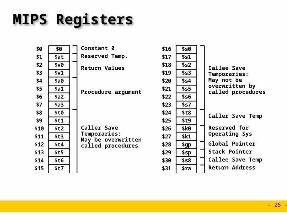
MIPS Registers
$0
$1
$2
$3
$4
$5
$6
$7
$8
$9
$10
$11
$12
$13
$14
$15
$0
$at
$v0
$v1
$a0
$a1
$a2
$a3
$t0
$t1
$t2
$t3
$t4
$t5
$t6
$t7
Constant 0
Reserved Temp.
Return Values
Procedure arguments
Caller SaveTemporaries:May be overwritten bycalled procedures
$16
$17
$18
$19
$20
$21
$22
$23
$24
$25
$26
$27
$28
$29
$30
$31
$s0
$s1
$s2
$s3
$s4
$s5
$s6
$s7
$t8
$t9
$k0
$k1
$gp
$sp
$s8
$ra
Reserved forOperating Sys
Caller Save Temp
Global Pointer
Callee SaveTemporaries:May not beoverwritten bycalled procedures
Stack Pointer
Callee Save Temp
Return Address

– 26 –
MIPS Instruction Examples
Op Ra Rb Offset
Op Ra Rb Rd Fn00000R-R
Op Ra Rb ImmediateR-I
Load/Store
addu $3,$2,$1 # Register add: $3 = $2+$1
addu $3,$2, 3145 # Immediate add: $3 = $2+3145sll $3,$2,2 # Shift left: $3 = $2 << 2
lw $3,16($2) # Load Word: $3 = M[$2+16]sw $3,16($2) # Store Word: M[$2+16] = $3
Op Ra Rb OffsetBranch
beq $3,$2,dest # Branch when $3 = $2

– 27 –
CISC vs. RISC
Original Debate Strong opinions! CISC proponents---easy for compiler, fewer code bytes RISC proponents---better for optimizing compilers, can make run fast
with simple chip design
Current Status For desktop processors, choice of ISA not a technical issue
With enough hardware, can make anything run fast Code compatibility more important
For embedded processors, RISC makes sense Smaller, cheaper, less power

– 28 –
Summary
Y86 Instruction Set Architecture Similar state and instructions as IA32 Simpler encodings Somewhere between CISC and RISC
How Important is ISA Design? Less now than before
With enough hardware, can make almost anything go fast AMD/Intel moved away from IA32
Does not allow enough parallel execution x86-64
» 64-bit word sizes (overcome address space limitations)» Radically different style of instruction set with explicit parallelism» Requires sophisticated compilers

Instructor:
Erol Sahin
Logic Design and HCLCENG331: Introduction to Computer Systems8th Lecture
Acknowledgement: Most of the slides are adapted from the ones prepared by R.E. Bryant, D.R. O’Hallaron of Carnegie-Mellon Univ.
– 30 –
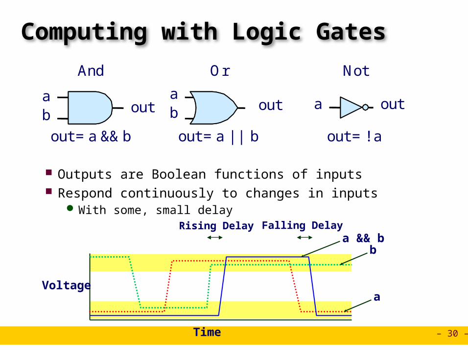
Computing with Logic Gates
Outputs are Boolean functions of inputs Respond continuously to changes in inputs
With some, small delay
ab out
ab out a out
out = a && b out = a || b out = !a
And Or Not
Voltage
Time
a
ba && b
Rising Delay Falling Delay

– 31 –
Combinational Circuits
Acyclic Network of Logic Gates Continously responds to changes on primary inputs Primary outputs become (after some delay) Boolean functions of
primary inputs
Acyclic Network
PrimaryInputs
PrimaryOutputs

– 32 –
Bit Equality
Generate 1 if a and b are equal
Hardware Control Language (HCL) Very simple hardware description language
Boolean operations have syntax similar to C logical operations We’ll use it to describe control logic for processors
Bit equala
b
eqbool eq = (a&&b)||(!a&&!b)
HCL Expression
– 33 –
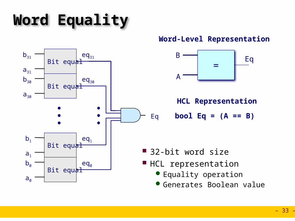
Word Equality
32-bit word size HCL representation
Equality operation Generates Boolean value
b31Bit equal
a31
eq31
b30Bit equal
a30
eq30
b1Bit equal
a1
eq1
b0Bit equal
a0
eq0
Eq
=B
A
Eq
Word-Level Representation
bool Eq = (A == B)
HCL Representation
– 34 –
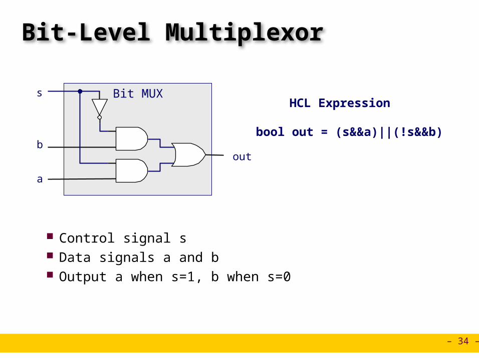
Bit-Level Multiplexor
Control signal s Data signals a and b Output a when s=1, b when s=0
Bit MUX
b
s
a
out
bool out = (s&&a)||(!s&&b)
HCL Expression

– 35 –
Word Multiplexor
Select input word A or B depending on control signal s
HCL representation Case expression Series of test : value pairs Output value for first successful test
Word-Level Representation
HCL Representation
b31
s
a31
out31
b30
a30
out30
b0
a0
out0
int Out = [ s : A; 1 : B;];
s
B
AOutMUX
– 36 –
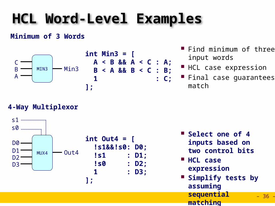
HCL Word-Level Examples
Find minimum of three input words
HCL case expression Final case guarantees matchA
Min3MIN3BC
int Min3 = [ A < B && A < C : A; B < A && B < C : B; 1 : C;];
D0
D3
Out4
s0s1
MUX4D2D1
Select one of 4 inputs based on two control bits
HCL case expression Simplify tests by
assuming sequential matching
int Out4 = [ !s1&&!s0: D0; !s1 : D1; !s0 : D2; 1 : D3;];
Minimum of 3 Words
4-Way Multiplexor
– 37 –
OFZFCF
OFZFCF
OFZFCF
OFZFCF
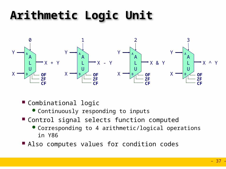
Arithmetic Logic Unit
Combinational logic Continuously responding to inputs
Control signal selects function computed Corresponding to 4 arithmetic/logical operations in Y86
Also computes values for condition codes
ALU
Y
X
X + Y
0
ALU
Y
X
X - Y
1
ALU
Y
X
X & Y
2
ALU
Y
X
X ^ Y
3
A
B
A
B
A
B
A
B

– 38 –
Registers
Stores word of data Different from program registers seen in assembly code
Collection of edge-triggered latches Loads input on rising edge of clock
I O
Clock
DC
Q+
DC
Q+
DC
Q+
DC
Q+
DC
Q+
DC
Q+
DC
Q+
DC
Q+
i7
i6
i5
i4
i3
i2
i1
i0
o7
o6
o5
o4
o3
o2
o1
o0
Clock
Structure
– 39 –
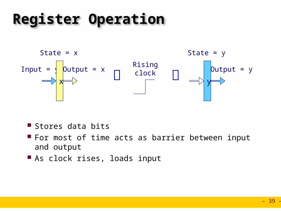
Register Operation
Stores data bits For most of time acts as barrier between input and output As clock rises, loads input
State = x
Risingclock
Output = xInput = y
x
State = y
Output = y
y

– 40 –
State Machine Example
Accumulator circuit Load or accumulate
on each cycle
Comb. Logic
ALU
0
OutMUX
0
1
Clock
In
Load
x0 x1 x2 x3 x4 x5
x0 x0+x1 x0+x1+x2 x3 x3+x4 x3+x4+x5
Clock
Load
In
Out

– 41 –
Random-Access Memory
Stores multiple words of memory Address input specifies which word to read or write
Register file Holds values of program registers %eax, %esp, etc. Register identifier serves as address
» ID 8 implies no read or write performed Multiple Ports
Can read and/or write multiple words in one cycle» Each has separate address and data input/output
Registerfile
A
B
W dstW
srcA
valA
srcB
valB
valW
Read ports Write port
Clock

– 42 –
Register File Timing
Reading Like combinational logic Output data generated based on input
address After some delay
Writing Like register Update only as clock rises
Registerfile
A
B
srcA
valA
srcB
valB
y2
Registerfile
W dstW
valW
Clock
x2
Risingclock Register
fileW dstW
valW
Clock
y2
x2
x
2

– 43 –
Hardware Control Language Very simple hardware description language Can only express limited aspects of hardware operation
Parts we want to explore and modify
Data Types bool: Boolean
a, b, c, … int: words
A, B, C, … Does not specify word size---bytes, 32-bit words, …
Statements bool a = bool-expr ; int A = int-expr ;

– 44 –
HCL Operations Classify by type of value returned
Boolean Expressions Logic Operations
a && b, a || b, !a Word Comparisons
A == B, A != B, A < B, A <= B, A >= B, A > B Set Membership
A in { B, C, D }» Same as A == B || A == C || A == D
Word Expressions Case expressions
[ a : A; b : B; c : C ] Evaluate test expressions a, b, c, … in sequence Return word expression A, B, C, … for first successful test

– 45 –
Summary
Computation Performed by combinational logic Computes Boolean functions Continuously reacts to input changes
Storage Registers
Hold single words Loaded as clock rises
Random-access memories Hold multiple words Possible multiple read or write ports Read word when address input changes Write word as clock rises

Instructor:
Erol Sahin
SEQuential processor implementationCENG331: Introduction to Computer Systems8th Lecture
Acknowledgement: Most of the slides are adapted from the ones prepared by R.E. Bryant, D.R. O’Hallaron of Carnegie-Mellon Univ.

– 47 –
Y86 Instruction SetByte 0 1 2 3 4 5
pushl rA A 0 rA 8
jXX Dest 7 fn Dest
popl rA B 0 rA 8
call Dest 8 0 Dest
rrmovl rA, rB 2 0 rA rB
irmovl V, rB 3 0 8 rB V
rmmovl rA, D(rB) 4 0 rA rB D
mrmovl D(rB), rA 5 0 rA rB D
OPl rA, rB 6 fn rA rB
ret 9 0
nop 0 0
halt 1 0
addl 6 0
subl 6 1
andl 6 2
xorl 6 3
jmp 7 0
jle 7 1
jl 7 2
je 7 3
jne 7 4
jge 7 5
jg 7 6

– 48 –
SEQ Hardware Structure
State Program counter register (PC) Condition code register (CC) Register File Memories
Access same memory space Data: for reading/writing program data Instruction: for reading instructions
Instruction Flow Read instruction at address specified by
PC Process through stages Update program counter
Instructionmemory
Instructionmemory
PCincrement
PCincrement
CCCCALUALU
Datamemory
Datamemory
Fetch
Decode
Execute
Memory
Write back
icode, ifunrA , rB
valC
Registerfile
Registerfile
A BM
E
Registerfile
Registerfile
A BM
E
PC
valP
srcA, srcBdstA, dstB
valA, valB
aluA, aluB
Bch
valE
Addr, Data
valM
PCvalE, valM
newPC

– 49 –
SEQ Stages
Fetch Read instruction from instruction
memory
Decode Read program registers
Execute Compute value or address
Memory Read or write data
Write Back Write program registers
PC Update program counter
Instructionmemory
Instructionmemory
PCincrement
PCincrement
CCCCALUALU
Datamemory
Datamemory
Fetch
Decode
Execute
Memory
Write back
icode, ifunrA , rB
valC
Registerfile
Registerfile
A BM
E
Registerfile
Registerfile
A BM
E
PC
valP
srcA, srcBdstA, dstB
valA, valB
aluA, aluB
Bch
valE
Addr, Data
valM
PCvalE, valM
newPC

– 50 –
Instruction Decoding
Instruction Format Instruction byte icode:ifun Optional register byte rA:rB Optional constant word valC
5 0 rA rB D
icodeifun
rArB
valC
Optional Optional

– 51 –
Executing Arith./Logical Operation
Fetch Read 2 bytes
Decode Read operand registers
Execute Perform operation Set condition codes
Memory Do nothing
Write back Update register
PC Update Increment PC by 2
OPl rA, rB 6 fn rA rB

– 52 –
Stage Computation: Arith/Log. Ops
Formulate instruction execution as sequence of simple steps Use same general form for all instructions
OPl rA, rB
icode:ifun M1[PC]
rA:rB M1[PC+1]
valP PC+2
Fetch
Read instruction byte
Read register byte
Compute next PC
valA R[rA]
valB R[rB]Decode
Read operand A
Read operand B
valE valB OP valA
Set CCExecute
Perform ALU operation
Set condition code register
Memory
R[rB] valE
Write
back
Write back result
PC valPPC update Update PC

– 53 –
Executing rmmovl
Fetch Read 6 bytes
Decode Read operand registers
Execute Compute effective address
Memory Write to memory
Write back Do nothing
PC Update Increment PC by 6
rmmovl rA, D(rB) 4 0 rA rB D
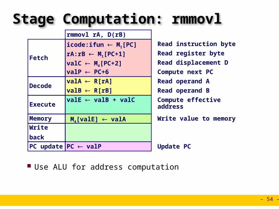
– 54 –
Stage Computation: rmmovl
Use ALU for address computation
rmmovl rA, D(rB)
icode:ifun M1[PC]
rA:rB M1[PC+1]
valC M4[PC+2]valP PC+6
Fetch
Read instruction byte
Read register byte
Read displacement D
Compute next PC
valA R[rA]
valB R[rB]Decode
Read operand A
Read operand B
valE valB + valCExecute
Compute effective address
M4[valE] valAMemory Write value to memory
Write
back
PC valPPC update Update PC
– 55 –
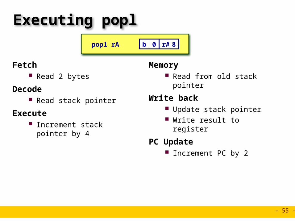
Executing popl
Fetch Read 2 bytes
Decode Read stack pointer
Execute Increment stack pointer by 4
Memory Read from old stack pointer
Write back Update stack pointer Write result to register
PC Update Increment PC by 2
popl rA b 0 rA 8
– 56 –
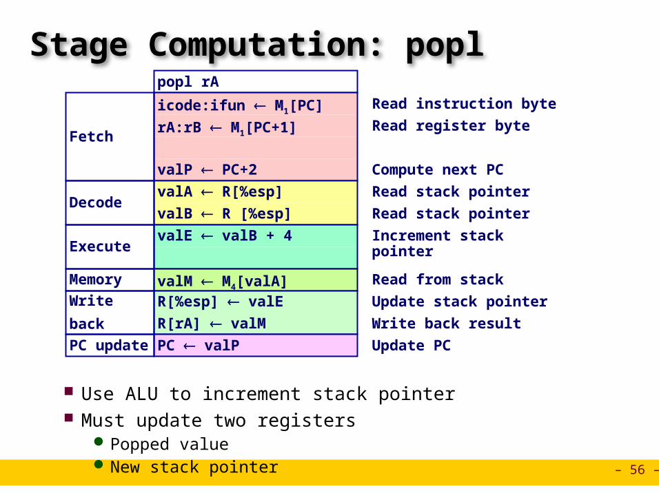
Stage Computation: popl
Use ALU to increment stack pointer Must update two registers
Popped value New stack pointer
popl rA
icode:ifun M1[PC]
rA:rB M1[PC+1]
valP PC+2
Fetch
Read instruction byte
Read register byte
Compute next PC
valA R[%esp]
valB R [%esp]Decode
Read stack pointer
Read stack pointer
valE valB + 4Execute
Increment stack pointer
valM M4[valA]Memory Read from stack
R[%esp] valE
R[rA] valM
Write
back
Update stack pointer
Write back result
PC valPPC update Update PC

– 57 –
Executing Jumps
Fetch Read 5 bytes Increment PC by 5
Decode Do nothing
Execute Determine whether to take
branch based on jump condition and condition codes
Memory Do nothing
Write back Do nothing
PC Update Set PC to Dest if branch taken or
to incremented PC if not branch
jXX Dest 7 fn Dest
XX XXfall thru:
XX XXtarget:
Not taken
Taken

– 58 –
Stage Computation: Jumps
Compute both addresses Choose based on setting of condition codes and branch condition
jXX Dest
icode:ifun M1[PC]
valC M4[PC+1]valP PC+5
Fetch
Read instruction byte
Read destination address
Fall through address
Decode
Bch Cond(CC,ifun)Execute
Take branch?
Memory
Write
back
PC Bch ? valC : valPPC update Update PC

– 59 –
Executing call
Fetch Read 5 bytes Increment PC by 5
Decode Read stack pointer
Execute Decrement stack pointer by 4
Memory Write incremented PC to new
value of stack pointer
Write back Update stack pointer
PC Update Set PC to Dest
call Dest 8 0 Dest
XX XXreturn:
XX XXtarget:
– 60 –
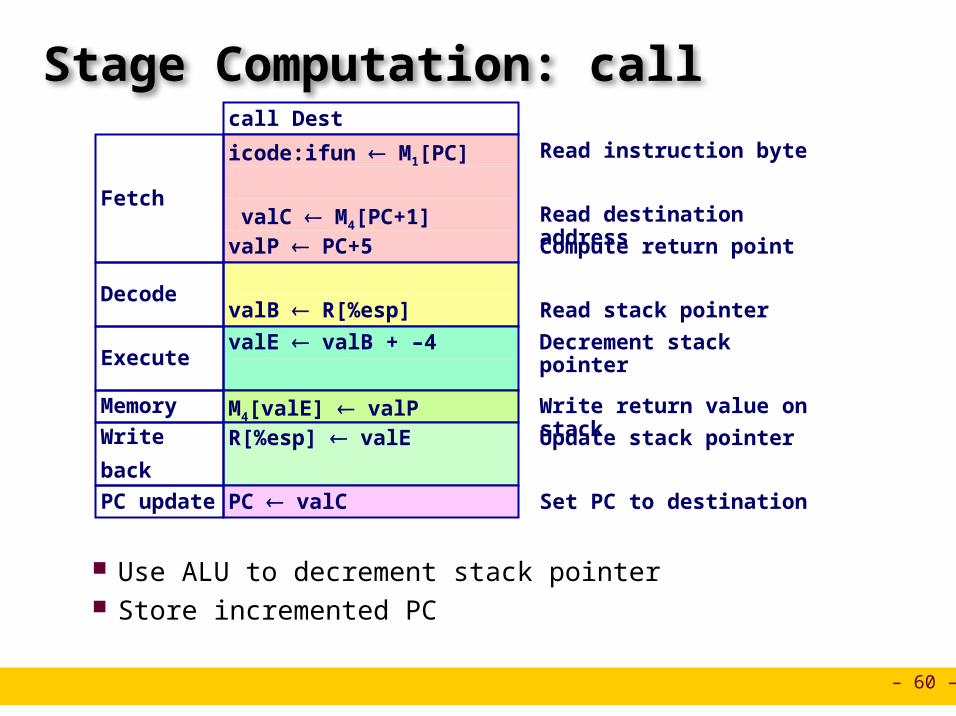
Stage Computation: call
Use ALU to decrement stack pointer Store incremented PC
call Dest
icode:ifun M1[PC]
valC M4[PC+1]valP PC+5
Fetch
Read instruction byte
Read destination address
Compute return point
valB R[%esp]Decode
Read stack pointer
valE valB + –4Execute
Decrement stack pointer
M4[valE] valP Memory Write return value on stack
R[%esp] valE
Write
back
Update stack pointer
PC valCPC update Set PC to destination
– 61 –
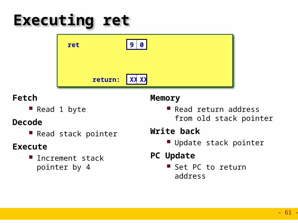
Executing ret
Fetch Read 1 byte
Decode Read stack pointer
Execute Increment stack pointer by 4
Memory Read return address from old
stack pointer
Write back Update stack pointer
PC Update Set PC to return address
ret 9 0
XX XXreturn:
– 62 –
Stage Computation: ret
Use ALU to increment stack pointer Read return address from memory
ret
icode:ifun M1[PC]
Fetch
Read instruction byte
valA R[%esp]
valB R[%esp]Decode
Read operand stack pointer
Read operand stack pointer
valE valB + 4Execute
Increment stack pointer
valM M4[valA] Memory Read return address
R[%esp] valE
Write
back
Update stack pointer
PC valMPC update Set PC to return address

– 63 –
Computation Steps
All instructions follow same general pattern Differ in what gets computed on each step
OPl rA, rB
icode:ifun M1[PC]
rA:rB M1[PC+1]
valP PC+2
Fetch
Read instruction byte
Read register byte
[Read constant word]
Compute next PC
valA R[rA]
valB R[rB]Decode
Read operand A
Read operand B
valE valB OP valA
Set CCExecute
Perform ALU operation
Set condition code register
Memory [Memory read/write]
R[rB] valE
Write
back
Write back ALU result
[Write back memory result]
PC valPPC update Update PC
icode,ifun
rA,rB
valC
valP
valA, srcA
valB, srcB
valE
Cond code
valM
dstE
dstM
PC
– 64 –
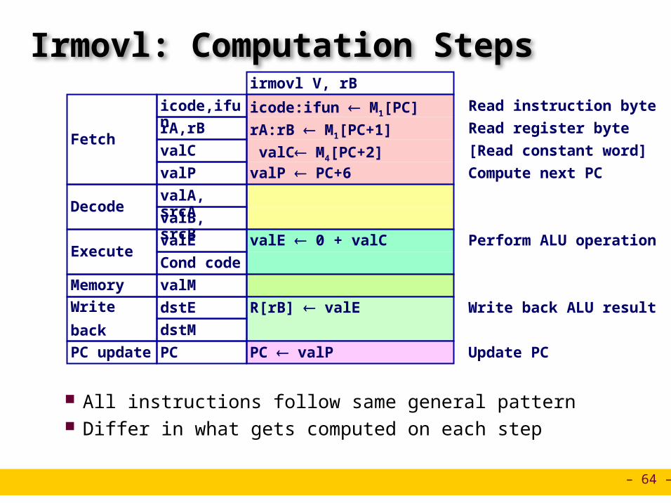
Irmovl: Computation Steps
All instructions follow same general pattern Differ in what gets computed on each step
irmovl V, rB
icode:ifun M1[PC]
rA:rB M1[PC+1]
valC M4[PC+2]valP PC+6
Fetch
Read instruction byte
Read register byte
[Read constant word]
Compute next PC
Decode
valE 0 + valCExecute
Perform ALU operation
Memory
R[rB] valE
Write
back
Write back ALU result
PC valPPC update Update PC
icode,ifun
rA,rB
valC
valP
valA, srcA
valB, srcB
valE
Cond code
valM
dstE
dstM
PC

– 65 –
Computation Steps
All instructions follow same general pattern Differ in what gets computed on each step
call Dest
Fetch
Decode
Execute
Memory
Write
back
PC update
icode,ifun
rA,rB
valC
valP
valA, srcA
valB, srcB
valE
Cond code
valM
dstE
dstM
PC
icode:ifun M1[PC]
valC M4[PC+1]valP PC+5
valB R[%esp]
valE valB + –4
M4[valE] valP R[%esp] valE
PC valC
Read instruction byte
[Read register byte]
Read constant word
Compute next PC
[Read operand A]
Read operand B
Perform ALU operation
[Set condition code reg.]
[Memory read/write]
[Write back ALU result]
Write back memory result
Update PC

– 66 –
Computed Values
Fetchicode Instruction codeifun Instruction functionrA Instr. Register ArB Instr. Register BvalC Instruction constantvalP Incremented PC
DecodesrcA Register ID AsrcB Register ID BdstE Destination Register EdstM Destination Register MvalA Register value AvalB Register value B
Execute valE ALU result Bch Branch flag
Memory valM Value from
memory

– 67 –
SEQ Hardware
Key Blue boxes: predesigned
hardware blocks E.g., memories, ALU
Gray boxes: control logic Describe in HCL
White ovals: labels for signals
Thick lines: 32-bit word values
Thin lines: 4-8 bit values
Dotted lines: 1-bit values
Instructionmemory
Instructionmemory
PCincrement
PCincrement
CCCC ALUALU
Datamemory
Datamemory
NewPC
rB
dstE dstM
ALUA
ALUB
Mem.control
Addr
srcA srcB
read
write
ALUfun.
Fetch
Decode
Execute
Memory
Write back
data out
Registerfile
Registerfile
A BM
E
Registerfile
Registerfile
A BM
E
Bch
dstE dstM srcA srcB
icode ifun rA
PC
valC valP
valBvalA
Data
valE
valM
PC
newPC
– 68 –
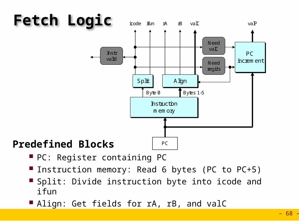
Fetch Logic
Predefined Blocks PC: Register containing PC Instruction memory: Read 6 bytes (PC to PC+5) Split: Divide instruction byte into icode and ifun Align: Get fields for rA, rB, and valC
Instructionmemory
Instructionmemory
PCincrement
PCincrement
rBicode ifun rA
PC
valC valP
Needregids
NeedvalC
Instrvalid
AlignAlignSplitSplit
Bytes 1-5Byte 0

– 69 –
Fetch Logic
Control Logic Instr. Valid: Is this instruction valid? Need regids: Does this instruction have a register bytes? Need valC: Does this instruction have a constant word?
Instructionmemory
Instructionmemory
PCincrement
PCincrement
rBicode ifun rA
PC
valC valP
Needregids
NeedvalC
Instrvalid
AlignAlignSplitSplit
Bytes 1-5Byte 0
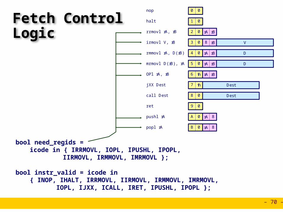
– 70 –
Fetch Control Logic
pushl rA A 0 rA 8
jXX Dest 7 fn Dest
popl rA B 0 rA 8
call Dest 8 0 Dest
rrmovl rA, rB 2 0 rA rB
irmovl V, rB 3 0 8 rB V
rmmovl rA, D(rB) 4 0 rA rB D
mrmovl D(rB), rA 5 0 rA rB D
OPl rA, rB 6 fn rA rB
ret 9 0
nop 0 0
halt 1 0
pushl rA A 0 rA 8pushl rA A 0A 0 rA 8rA 8
jXX Dest 7 fn DestjXX Dest 7 fn7 fn Dest
popl rA B 0 rA 8popl rA B 0B 0 rA 8rA 8
call Dest 8 0 Destcall Dest 8 08 0 Dest
rrmovl rA, rB 2 0 rA rBrrmovl rA, rB 2 02 0 rA rBrA rB
irmovl V, rB 3 0 8 rB Virmovl V, rB 3 03 0 8 rB8 rB V
rmmovl rA, D(rB) 4 0 rA rB Drmmovl rA, D(rB) 4 04 0 rA rBrA rB D
mrmovl D(rB), rA 5 0 rA rB Dmrmovl D(rB), rA 5 05 0 rA rBrA rB D
OPl rA, rB 6 fn rA rBOPl rA, rB 6 fn6 fn rA rBrA rB
ret 9 0ret 9 09 0
nop 0 0nop 0 00 0
halt 1 0halt 1 01 0
bool need_regids =icode in { IRRMOVL, IOPL, IPUSHL, IPOPL,
IIRMOVL, IRMMOVL, IMRMOVL };
bool instr_valid = icode in { INOP, IHALT, IRRMOVL, IIRMOVL, IRMMOVL, IMRMOVL, IOPL, IJXX, ICALL, IRET, IPUSHL, IPOPL };

– 71 –
Decode Logic
Register File Read ports A, B Write ports E, M Addresses are register IDs or 8 (no
access)
rB
dstE dstM srcA srcB
Registerfile
Registerfile
A BM
EdstE dstM srcA srcB
icode rA
valBvalA valEvalM
Control Logic srcA, srcB: read port
addresses dstA, dstB: write port
addresses

– 72 –
A SourceOPl rA, rB
valA R[rA]Decode Read operand A
rmmovl rA, D(rB)
valA R[rA]Decode Read operand A
popl rA
valA R[%esp]Decode Read stack pointer
jXX Dest
Decode No operand
call Dest
valA R[%esp]Decode Read stack pointer
ret
Decode No operand
int srcA = [icode in { IRRMOVL, IRMMOVL, IOPL, IPUSHL } : rA;icode in { IPOPL, IRET } : RESP;1 : RNONE; # Don't need register
];

– 73 –
E Destination
None
R[%esp] valE Update stack pointer
None
R[rB] valE
OPl rA, rB
Write-back
rmmovl rA, D(rB)
popl rA
jXX Dest
call Dest
ret
Write-back
Write-back
Write-back
Write-back
Write-back
Write back result
R[%esp] valE Update stack pointer
R[%esp] valE Update stack pointer
int dstE = [icode in { IRRMOVL, IIRMOVL, IOPL} : rB;icode in { IPUSHL, IPOPL, ICALL, IRET } : RESP;1 : RNONE; # Don't need register
];

– 74 –
Execute Logic
Units ALU
Implements 4 required functions Generates condition code values
CC Register with 3 condition code bits
bcond Computes branch flag
Control Logic Set CC: Should condition code register
be loaded? ALU A: Input A to ALU ALU B: Input B to ALU ALU fun: What function should ALU
compute?
CCCC ALUALU
ALUA
ALUB
ALUfun.
Bch
icode ifun valC valBvalA
valE
SetCC
bcondbcond

– 75 –
ALU A Input
valE valB + –4 Decrement stack pointer
No operation
valE valB + 4 Increment stack pointer
valE valB + valC Compute effective address
valE valB OP valA Perform ALU operation
OPl rA, rB
Execute
rmmovl rA, D(rB)
popl rA
jXX Dest
call Dest
ret
Execute
Execute
Execute
Execute
Execute valE valB + 4 Increment stack pointer
int aluA = [icode in { IRRMOVL, IOPL } : valA;icode in { IIRMOVL, IRMMOVL, IMRMOVL } : valC;icode in { ICALL, IPUSHL } : -4;icode in { IRET, IPOPL } : 4;# Other instructions don't need ALU
];

– 76 –
ALU Operation
valE valB + –4 Decrement stack pointer
No operation
valE valB + 4 Increment stack pointer
valE valB + valC Compute effective address
valE valB OP valA Perform ALU operation
OPl rA, rB
Execute
rmmovl rA, D(rB)
popl rA
jXX Dest
call Dest
ret
Execute
Execute
Execute
Execute
Execute valE valB + 4 Increment stack pointer
int alufun = [icode == IOPL : ifun;1 : ALUADD;
];

– 77 –
Memory Logic
Memory Reads or writes memory word
Control Logic Mem. read: should word be
read? Mem. write: should word be
written? Mem. addr.: Select address Mem. data.: Select data
Datamemory
Datamemory
Mem.read
Memaddr
read
write
data out
Memdata
valE
valM
valA valP
Mem.write
data in
icode

– 78 –
Memory AddressOPl rA, rB
Memory
rmmovl rA, D(rB)
popl rA
jXX Dest
call Dest
ret
No operation
M4[valE] valAMemory Write value to memory
valM M4[valA]Memory Read from stack
M4[valE] valP Memory Write return value on stack
valM M4[valA] Memory Read return address
Memory No operation
int mem_addr = [icode in { IRMMOVL, IPUSHL, ICALL, IMRMOVL } : valE;icode in { IPOPL, IRET } : valA;# Other instructions don't need address
];

– 79 –
Memory Read
OPl rA, rB
Memory
rmmovl rA, D(rB)
popl rA
jXX Dest
call Dest
ret
No operation
M4[valE] valAMemory Write value to memory
valM M4[valA]Memory Read from stack
M4[valE] valP Memory Write return value on stack
valM M4[valA] Memory Read return address
Memory No operation
bool mem_read = icode in { IMRMOVL, IPOPL, IRET };

– 80 –
PC Update Logic
New PC Select next value of PC
NewPC
Bchicode valC valPvalM
PC

– 81 –
PCUpdate
OPl rA, rB
rmmovl rA, D(rB)
popl rA
jXX Dest
call Dest
ret
PC valPPC update Update PC
PC valPPC update Update PC
PC valPPC update Update PC
PC Bch ? valC : valPPC update Update PC
PC valCPC update Set PC to destination
PC valMPC update Set PC to return address
int new_pc = [icode == ICALL : valC;icode == IJXX && Bch : valC;icode == IRET : valM;1 : valP;
];
– 82 –
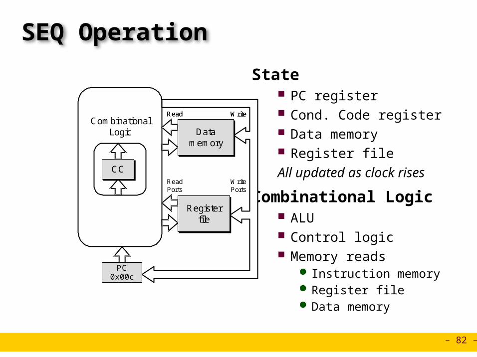
SEQ Operation
State PC register Cond. Code register Data memory Register fileAll updated as clock rises
Combinational Logic ALU Control logic Memory reads
Instruction memory Register file Data memory
CombinationalLogic Data
memoryData
memory
Registerfile
Registerfile
PC0x00c
CCCCReadPorts
WritePorts
Read WriteRead Write

– 83 –
CombinationalLogic Data
memoryData
memory
Registerfile
%ebx = 0x100
Registerfile
%ebx = 0x100
PC0x00c
CC100CC100
ReadPorts
WritePorts
Read WriteRead Write
0x00c: addl %edx,%ebx # %ebx <-- 0x300 CC <-- 000
0x00e: je dest # Not taken
Cycle 3:
Cycle 4:
0x006: irmovl $0x200,%edx # %edx <-- 0x200Cycle 2:
0x000: irmovl $0x100,%ebx # %ebx <-- 0x100Cycle 1:
Clock
Cycle 1 Cycle 2 Cycle 3 Cycle 4
SEQ Operation #2
state set according to second irmovl instruction
combinational logic starting to react to state changes
– 84 –
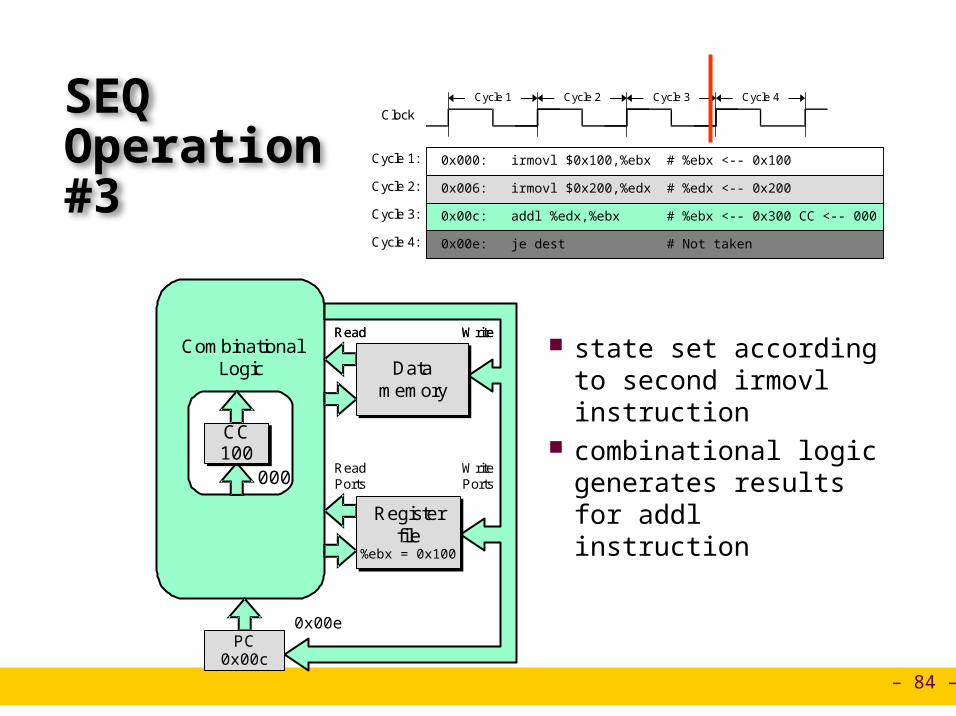
0x00c: addl %edx,%ebx # %ebx <-- 0x300 CC <-- 000
0x00e: je dest # Not taken
Cycle 3:
Cycle 4:
0x006: irmovl $0x200,%edx # %edx <-- 0x200Cycle 2:
0x000: irmovl $0x100,%ebx # %ebx <-- 0x100Cycle 1:
Clock
Cycle 1 Cycle 2 Cycle 3 Cycle 4
SEQ Operation #3
state set according to second irmovl instruction
combinational logic generates results for addl instruction
CombinationalLogic Data
memoryData
memory
Registerfile
%ebx = 0x100
Registerfile
%ebx = 0x100
PC0x00c
CC100CC100
ReadPorts
WritePorts
0x00e
000
Read WriteRead Write

– 85 –
0x00c: addl %edx,%ebx # %ebx <-- 0x300 CC <-- 000
0x00e: je dest # Not taken
Cycle 3:
Cycle 4:
0x006: irmovl $0x200,%edx # %edx <-- 0x200Cycle 2:
0x000: irmovl $0x100,%ebx # %ebx <-- 0x100Cycle 1:
Clock
Cycle 1 Cycle 2 Cycle 3 Cycle 4
SEQ Operation #4
state set according to addl instruction
combinational logic starting to react to state changes
CombinationalLogic Data
memoryData
memory
Registerfile
%ebx = 0x300
Registerfile
%ebx = 0x300
PC0x00e
CC000CC000
ReadPorts
WritePorts
Read WriteRead Write

– 86 –
0x00c: addl %edx,%ebx # %ebx <-- 0x300 CC <-- 000
0x00e: je dest # Not taken
Cycle 3:
Cycle 4:
0x006: irmovl $0x200,%edx # %edx <-- 0x200Cycle 2:
0x000: irmovl $0x100,%ebx # %ebx <-- 0x100Cycle 1:
Clock
Cycle 1 Cycle 2 Cycle 3 Cycle 4
SEQ Operation #5
state set according to addl instruction
combinational logic generates results for je instruction
CombinationalLogic Data
memoryData
memory
Registerfile
%ebx = 0x300
Registerfile
%ebx = 0x300
PC0x00e
CC000CC000
ReadPorts
WritePorts
0x013
CombinationalLogic Data
memoryData
memory
Registerfile
%ebx = 0x300
Registerfile
%ebx = 0x300
PC0x00e
CC000CC000
ReadPorts
WritePorts
0x013
Read WriteRead Write

– 87 –
SEQ Summary
Implementation Express every instruction as series of simple steps Follow same general flow for each instruction type Assemble registers, memories, predesigned combinational blocks Connect with control logic
Limitations Too slow to be practical In one cycle, must propagate through instruction memory, register file,
ALU, and data memory Would need to run clock very slowly Hardware units only active for fraction of clock cycle