instructions - mid-american glass | homemidamericanglass.com/installationtrifabvg.pdfstack with...
TRANSCRIPT

1
INSTALLATION
INSTRUCTIONSLITHO IN U.S.A. JANUARY ®KAWNEER COMPANY, INC., 2004 PART NO. 451-VG-970451-VG-970.01.04a
TRIFAB® VGSCREW SPLINE ASSEMBLY
TRIFAB VG 450TRIFAB VG 451TRIFAB VG 451T
···
2
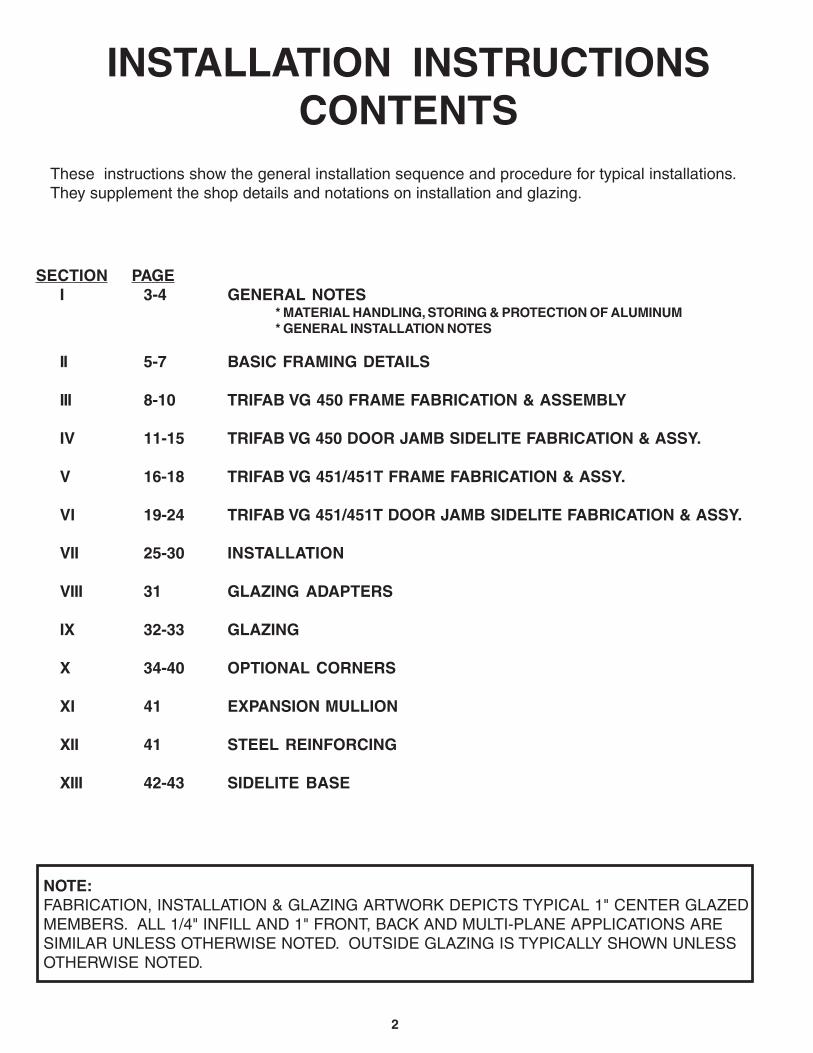
INSTALLATION INSTRUCTIONSCONTENTS
These instructions show the general installation sequence and procedure for typical installations.They supplement the shop details and notations on installation and glazing.
SECTION PAGEI 3-4 GENERAL NOTES
* MATERIAL HANDLING, STORING & PROTECTION OF ALUMINUM* GENERAL INSTALLATION NOTES
II 5-7 BASIC FRAMING DETAILS
III 8-10 TRIFAB VG 450 FRAME FABRICATION & ASSEMBLY
IV 11-15 TRIFAB VG 450 DOOR JAMB SIDELITE FABRICATION & ASSY.
V 16-18 TRIFAB VG 451/451T FRAME FABRICATION & ASSY.
VI 19-24 TRIFAB VG 451/451T DOOR JAMB SIDELITE FABRICATION & ASSY.
VII 25-30 INSTALLATION
VIII 31 GLAZING ADAPTERS
IX 32-33 GLAZING
X 34-40 OPTIONAL CORNERS
XI 41 EXPANSION MULLION
XII 41 STEEL REINFORCING
XIII 42-43 SIDELITE BASE
NOTE:FABRICATION, INSTALLATION & GLAZING ARTWORK DEPICTS TYPICAL 1" CENTER GLAZEDMEMBERS. ALL 1/4" INFILL AND 1" FRONT, BACK AND MULTI-PLANE APPLICATIONS ARESIMILAR UNLESS OTHERWISE NOTED. OUTSIDE GLAZING IS TYPICALLY SHOWN UNLESSOTHERWISE NOTED.

3
HANDLING, STORING, AND PROTECTION OF ALUMINUM
GENERAL INSTALLATION NOTES
The material must be protected against damage. The following precautions are recommended to assureearly acceptance of your products and workmanship.
A. HANDLE CAREFULLY - Don’t drop from the truck. Stack with adequate separation so material willnot rub together. Store off ground. Protect against elements and other construction trades. Wear handprotection to prevent injury due to sharp edges of cut extrusions.
B. KEEP MATERIAL AWAY FROM WATER, MUD AND SPRAY - Prevent cement, plaster, or othermaterials from damaging the finish.
C. PROTECT THE MATERIALS AFTER ERECTION - Protect by wrapping with Kraft paper or by erectingVisqueen or canvas splatter screen. Cement, plaster, terrazzo, other alkaline solutions and acidbased materials used to clean masonry are very harmful to the finish and should be removed withwater and mild soap IMMEDIATELY.
The following practices are recommended for all installations:
A. CHECK SHOP DRAWINGS, INSTALLATION INSTRUCTIONS and GLAZING INSTRUCTIONS tobecome thoroughly familiar with the project. The SHOP DRAWINGS take precedence and includespecific details for the project. The INSTALLATION INSTRUCTIONS are of a general nature andcover most common conditions.
B. All materials are to be INSTALLED PLUMB, LEVEL, AND TRUE.
C. All work should start from bench marks and/or column lines as established by the ARCHITECTURALDRAWINGS and the GENERAL CONTRACTOR. Check mullion spacing from both ends of masonryopening to prevent dimensional build-up of day light opening.
D. Make certain that construction which will receive your materials is in accordance with the contractdocuments. If not, notify the GENERAL CONTRACTOR IN WRITING and resolve differences beforeproceeding with your work.
E. Isolate all aluminum to be placed directly in contact with uncured masonry or incompatible materialswith a heavy coat of zinc chromate or bituminous paint.
F. Check all materials on arrival for quantity and be sure you have everything required to begininstallation.
G. Sealants must be compatible with all materials with which they have contact, including other sealantsurfaces. Consult with sealant manufacturer for recommendations relative to joint size, shelf life,compatibility, priming, tooling, adhesion, etc.
H. FASTENING - “Fastening” means any method of securing one part to another or to adjacentmaterials. These instructions specify only those fasteners used within the system.Due to varying perimeter conditions and job performance requirements, anchor fasteners are notspecified in these instructions. For anchor fastening, refer to the Shop Drawings or consult thefastener supplier.
I. CHECK OPENINGS - Make certain that the opening which will receive your materials is in accordancewith the contract documents. If not, notify the General Contractor in writing and resolve differencesbefore proceeding with your work.
J. BUILDING CODES - Glass and glazing codes governing the design and use of products vary widely.Kawneer does not control the selection of product configurations, operating hardware, or glazingmaterials, and assumes no responsibility for these design considerations. It is the responsibility of theowner, specifier, architect, general contractor and the installer to make these selections in strictconformance with all applicable codes.
K. EXPANSION JOINTS - Expansion joints and perimeter seals shown in these instructions and in theshop drawings are shown at normal size. Actual dimensions may vary due to perimeter conditions and/or difference in metal temperature between the time of fabrication and time of installation. For example,a 12 foot unrestrained length of aluminum extrusion can expand or contract 3/32” over a 50° Ftemperature change. Any movement potential should be accounted for at the time of installation.
SECTION I - GENERAL NOTES

4
L. FIELD TESTING - It is recommended that a Water Hose Test be conducted once a sufficient portion ofthe framing is installed, glazed and caulked to ensure proper installation. The Water Hose Test shall beconducted in accordance with AAMA 501.2. In addition, larger projects should have periodic WaterHose Tests as additional precautionary measures.
M. GASKET INVENTORY ROTATION - These high quality rubber extrusions are coated with siliconelubricant. Silicone will dry over time leaving a white “chalky” residue. Please rotate your stock“FIRST IN - FIRST OUT”. If the rubber becomes dry, you may use water ONE TIME to reconstitutethe silicone, after that, use a soap water solution.
SECTION I - GENERAL NOTES

5
1
4 5
2
3
SECTION II - BASIC FRAMING DETAILSThe Screw Spline System is a fabrication and erection method that permits the pre-assembly of singleunits in the shop or at the job site. These units are then erected by mating the male mullion half of one unit withthe female half of the unit already installed.
ELEVATION IS NUMBER KEYED TO DETAILS
TRIFAB® VG 451TTHERMALLY BROKEN MEMBERS
CENTER FRONT BACK
4JAMB
4JAMB
4JAMB
1HEAD
1HEAD
1HEAD
2HORIZONTAL
2HORIZONTAL
2HORIZONTAL
3SILL
3SILL
3SILL
5VERTICAL
5VERTICAL
5VERTICAL

6
1
4 5
2
3
SECTION II - BASIC FRAMING DETAILSINSIDE GLAZED DETAILS SHOWN
ELEVATION IS NUMBER KEYED TO DETAILS
TRIFAB® VG 451TTHERMALLY BROKEN MEMBERS
CENTER FRONT BACK
4JAMB
4JAMB
4JAMB
1HEAD
1HEAD
1HEAD
2HORIZONTAL
2HORIZONTAL
2HORIZONTAL
3SILL
3SILL
3SILL
5VERTICAL
5VERTICAL
5VERTICAL

7
SECTION II - BASIC FRAMING DETAILS
ELEVATION IS NUMBER KEYED TO DETAILS
CENTERFRONT BACK
MULTI-PLANE
10JAMB
12VERTICAL
1HEAD
4HEAD
7HEAD
2HORIZONTAL
5HORIZONTAL
8HORIZONTAL
3SILL
6SILL
9SILL
11VERTICAL
13VERTICAL
14JAMB
1 74
10
FRONT BACK CENTER FRONT
11 12 13 14
2 85
3 96
TRIFAB® VG 451TTHERMALLY BROKEN MEMBERS

8
OUTSIDE GLAZED (STOPS DOWN)
HEAD PREP = HOLES ( )E, L
HORIZONTAL PREP = HOLES ( )E, L
SILL PREP = HOLES ( )A, C
HEAD PREP = HOLES ( )J, L
HORIZONTAL PREP = HOLES ( )C, H
SILL PREP = HOLES ( )C, H
HEAD PREP = HOLES ( )E, L
HORIZONTAL PREP = HOLES ( )E, L
SILL PREP = HOLES ( )A, C
OUTSIDE GLAZED (STOPS UP)
INSIDE GLAZED
PLACE JIG ONTO MULLION AS SHOWN BELOW PLACE JIG ONTO MULLION AS SHOWN BELOW
No. 1 DRILL450-VG-201
J
FR
ON
T
E
H
BOTTOM
K
F
L M
G
BA
CK
A BTOP DC
4 1/2"
1-1/32"
1 3/
4"
2-7/16"
3/16
"
17/3
2"17
/32"
3/16
"
No. 1 DRILL450-VG-201
J
FR
ON
T
E
H
BOTTOM
K
F
LM
G
BA
CK
AB TOPD C
4 1/2"
1-1/32"2-7/16"
D.L
.O.
FR
AM
E H
EIG
HT
SECTION III - FRAME FABRICATION & ASSEMBLYSCREW SPLINE PREPS FOR CENTER OPTION
TRIFAB VG 450 (CENTER OPTION)TRIFAB VG 450 (CENTER OPTION)
1 3/
4"
3/16
"
17/3
2"17
/32"
3/16
"
D.L
.O.
FR
AM
E H
EIG
HT
#1 DRILL(TYPICAL)
#1 DRILL(TYPICAL)
Step A:1/8" 7/16"
Step B:
Measure the opening to determine length of vertical and horizontal framing members. For all units that require sillflashing, allow a minimum of for standard flashing and for high-performance flashing when measuringvertical lengths. Allow 1/4" min. clearance at the head, sill, and each jamb to facilitate installation and providespace for caulking. If job conditions are uncertain, or masonry openings are irregular, or if high-performanceflashing is used, allow extra clearance to accommodate construction tolerance.
Cut vertical members to required length (Frame Height). At desired horizontal locations drill the proper holes in thevertical members for attachment of the spline screws, as shown below.

9
No. 1 DRILL450-VG-201
J
FR
ON
T
E
H
BOTTOM
K
F
L M
G
BA
CK
A BTOP DC
No. 1 DRILL450-VG-201
J
FR
ON
T
E
H
BOTTOM
K
F
LM
GBA
CK
AB TOPD C
OUTSIDE GLAZED
4 1/2"
1-25/32"
23/3
2"
1 3/
4"
15/16"
3/16
"
HEAD PREP = HOLES ( )K, M
HORIZONTAL PREP = HOLES ( )B, D
SILL PREP = HOLES ( )B, D
HEAD PREP = HOLES ( )F, G
HORIZONTAL PREP = HOLES ( )B, D
SILL PREP = HOLES ( )B, D
OUTSIDE GLAZED
4 1/2"
1-25/32"15/16"
3/16
"
HEAD PREP = HOLES ( )F, G
HORIZONTAL PREP = HOLES ( )B, D
SILL PREP = HOLES ( )B, D
HORIZONTAL PREP = HOLES ( )B, D
HEAD PREP = HOLES ( )K, M
SILL PREP = HOLES ( )B, D
INSIDE GLAZED INSIDE GLAZED
D.L
.O.
FR
AM
E H
EIG
HT
PLACE JIG ONTO MULLION AS SHOWN BELOW PLACE JIG ONTO MULLION AS SHOWN BELOW
23/3
2"
1 3/
4"
3/16
"3/
16"
D.L
.O.
FR
AM
E H
EIG
HT
MULLION FILLERMULLION FILLER
SECTION III - FRAME FABRICATION & ASSEMBLYSCREW SPLINE PREPS FOR FRONT or BACK OPTION
Step A:1/8" 7/16"
Step B:
Measure the opening to determine length of vertical and horizontal framing members. For all units that require sillflashing, allow a minimum of for standard flashing and for high-performance flashing when measuringvertical lengths. Allow 1/4" min. clearance at the head, sill, and each jamb to facilitate installation and providespace for caulking. If job conditions are uncertain, or masonry openings are irregular, or if high-performanceflashing is used, allow extra clearance to accommodate construction tolerance.
Cut vertical members to required length (Frame Height). At desired horizontal locations drill the proper holes in thevertical members for attachment of the spline screws, as shown below.
TRIFAB VG 450 (BACK OPTION)TRIFAB VG 450 (FRONT OPTION)
#1 DRILL(TYPICAL)
#1 DRILL(TYPICAL)
Screw spline preps for mullion fillers may be completed by using a 2" piece of the mullion to support drill jigor by locating the horizontal at the vertical dimensions shown above, and drilling at the "V" grooves in the extrusion.
10
HEAD
3" LONGSHIMFILLER
3" LONGSHIMFILLER
INTERMEDIATEHORIZONTAL
SEALANT
SEALANT
SEALANT
SILL
SCREW SPLINEMULLION
#12 x 1-1/8" SPLINE SCREWS
SNAP IN FILLER
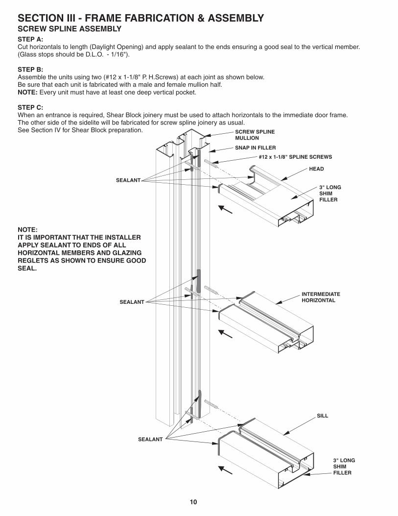
NOTE:IT IS IMPORTANT THAT THE INSTALLERAPPLY SEALANT TO ENDS OF ALLHORIZONTAL MEMBERS AND GLAZINGREGLETS AS SHOWN TO ENSURE GOODSEAL.
STEP A:
STEP B:
NOTE:
STEP C:
Cut horizontals to length (Daylight Opening) and apply sealant to the ends ensuring a good seal to the vertical member.(Glass stops should be D.L.O. - 1/16").
Assemble the units using two (#12 x 1-1/8" P. H.Screws) at each joint as shown below.Be sure that each unit is fabricated with a male and female mullion half.
Every unit must have at least one deep vertical pocket.
When an entrance is required, Shear Block joinery must be used to attach horizontals to the immediate door frame.
See Section IV for Shear Block preparation.The other side of the sidelite will be fabricated for screw spline joinery as usual.
SECTION III - FRAME FABRICATION & ASSEMBLYSCREW SPLINE ASSEMBLY

11
OUTSIDE GLAZED (STOPS DOWN)
HEAD PREP = HOLES ( )B, J, K
HORIZONTAL PREP = HOLES ( )B, J, K
SILL PREP = HOLES ( )B, J, K
HEAD PREP = HOLES ( )A, B, K
HORIZONTAL PREP = HOLES ( )A, B, K
SILL PREP = HOLES ( )A, B, K
INSIDE GLAZED
HEAD PREP = HOLES ( )A, B, K
HORIZONTAL PREP = HOLES ( )A, B, K
SILL PREP = HOLES ( )A, B, K
PLACE JIG ONTO MULLION AS SHOWN BELOW
OUTSIDE GLAZED (STOPS UP)
PLACE JIG ONTO MULLION AS SHOWN BELOW
TRIFAB VG 450 (CENTER OPTION) TRIFAB VG 450 (CENTER OPTION)
A
FR
ON
T
J
450-VG-200No. 26 DRILL
B
BOTTOM
K
G
EC
H BA
CK
F
D
TOP
4 1/2"
1-7/16"
1 3/
4"
1-5/8"
5/16
"
D.L
.O.
DO
OR
FR
AM
E H
EIG
HT
5/16
"
#26 DRILL(TYPICAL)
SH
IM S
PAC
E
SECTION IV - DOOR JAMB SIDELITE FABRICATION & ASSEMBLYSHEAR BLOCK PREPS FOR CENTER OPTION
A
FR
ON
T
J
450-VG-200No. 26 DRILL
B
BOTTOM
K
G
EC
HBA
CK
F
D
TOP
4 1/2"
1-7/16"
1 3/
4"
1-5/8"
5/16
"
D.L
.O.
DO
OR
FR
AM
E H
EIG
HT
5/16
"
#26 DRILL(TYPICAL)
Step A:
Important Note:
Step B:
At desired horizontal locations drill the proper holes in the door jambs for attachment of the shear blocks, asshown below.
Door Jambs run through to perimeter at sill. Locate sill to accommodate sill flashing and shimspace at sill.
Attach shear blocks to door jambs using #28-400 (#10 x 1-19/32" P.H.) screws as required.
SH
IM S
PAC
E

12
5/8
"
1"
SILL
HORIZONTAL
HEAD
SECTION IV - DOOR JAMB SIDELITE FABRICATION & ASSEMBLYSHEAR BLOCK PREPS FOR CENTER OPTION
Cut horizontals to length = Daylight Opening, (Glass stops should be D.L.O. - 1/16").
Fabricate head, sill, and intermediate horizontals by drilling and countersinking for #10 F.H. screws.
Step C:
Step D:
1"
1/2"
.201" DIA. HOLE (#7 drill)
.390" DIA. x 82° COUNTERSINK(TYP.)
5/8
"
1"

13
OUTSIDE GLAZED
HEAD PREP = HOLES ( )C, D
HORIZONTAL PREP = HOLES ( )E, F
SILL PREP = HOLES ( )E, F
OUTSIDE GLAZED
HEAD PREP = HOLES ( )G, H
HORIZONTAL PREP = HOLES ( )E, F
SILL PREP = HOLES ( )E, F
HORIZONTAL PREP = HOLES ( )E, F
HEAD PREP = HOLES ( )C, D
SILL PREP = HOLES ( )E, F
INSIDE GLAZED INSIDE GLAZED
HEAD PREP = HOLES ( )G, H
HORIZONTAL PREP = HOLES ( )E, F
SILL PREP = HOLES ( )E, F
PLACE JIG ONTO MULLION AS SHOWN BELOW PLACE JIG ONTO MULLION AS SHOWN BELOW
TRIFAB VG 450 (BACK OPTION)TRIFAB VG 450 (FRONT OPTION)
A
FR
ON
T
J
450-VG-200No. 26 DRILL
B
BOTTOM
K
G
E
C
H BA
CK
F
D
TOP
4 1/2"
1-25/32"
1-1/
16"
1 3/
4"
15/16"
15/3
2"
11/1
6"
D.L
.O.
DO
OR
FR
AM
E H
EIG
HT
#26 DRILL(TYPICAL)
A
FR
ON
T
J
450-VG-200No. 26 DRILL
B
BOTTOM
K
G
E
C
HBA
CK
F
D
TOP
4 1/2"
1-25/32"
1-1/
16"
1 3/
4"
15/16"
15/3
2"
11/1
6"
D.L
.O.
#26 DRILL(TYPICAL)
SH
IM S
PAC
E
SECTION IV - DOOR JAMB SIDELITE FABRICATION & ASSEMBLYSHEAR BLOCK PREPS FOR FRONT or BACK OPTION
Step A:
Important Note:
Step B:
At desired horizontal locations drill the proper holes in the door jambs for attachment of the shear blocks, asshown below.
Door Jambs run through to perimeter at sill. Locate sill to accommodate sill flashing and shimspace at sill.
Attach shear blocks to door jambs using #28-400 (#10 x 1-19/32" P.H.) screws as required.
DO
OR
FR
AM
E H
EIG
HT
SH
IM S
PAC
E

14
1"1"
1"1-1/2" .201" DIA. HOLE
(#7 Drill).390" DIA. x 82° COUNTERSINK
.201" DIA. HOLE(#7 Drill)
5/8
"
1"
SECTION IV - DOOR JAMB SIDELITE FABRICATION & ASSEMBLYSHEAR BLOCK PREPS FOR FRONT OR BACK OPTIONS
Cut horizontals to length = Daylight Opening, (Glass Stops should be D.L.O. - 1/16").
Fabricate head and sill by drilling and countersinking for #10 F.H. screws.
Step C:
Step D:
SILL
HEAD
FRONT - INSIDE GLAZEDOR
BACK - OUTSIDE GLAZED
FRONT - OUTSIDE GLAZEDOR
BACK - INSIDE GLAZED

15
DOOR JAMB
HEAD
3" LONGSHIMFILLER
3" LONGSHIMFILLER
HEADSHEAR BLOCKPACKAGE
INTERMEDIATE HORIZONTALSHEAR BLOCK PACKAGE
INTERMEDIATEHORIZONTAL
SEALANTINTO REGLET
SEALANT
SEALANT
SEALANT
SEALANT
SILL
SILLSHEAR BLOCKPACKAGE
VERTICALSIDE
D.L.O.SIDE
FIGURE #1FOR CENTER OPTION
INTERMEDIATE HORIZONTALS
FIGURE #2FOR FRONT OR BACK OPTIONINTERMEDIATE HORIZONTALS
NOTE:IT IS IMPORTANT THAT THE INSTALLERAPPLY SEALANT TO SHEAR BLOCKS,ENDS OF ALL HORIZONTAL MEMBERSAND GLAZING REGLETS AS SHOWNTO ENSURE GOOD SEAL.
STEP E:Install flat fillers into head, jamb and sill at perimeteranchor locations.Crimp material to prevent filler plate from sliding.Perimeter anchors should be located within 6" oneach side of vertical mullions and 24" O.C. betweenvertical mullions.
STEP D:Continue procedure above until entire frame is assembled.
STEP C:Attach horizontal members to shear blocks with fasteners provided in shear block packages.
STEP B:Apply sealant to the ends of all horizontal members, shear blocks and into reglets as shown below.
STEP A: FOR CENTER OPTION INTERMEDIATE HORIZONTALSHold fabricated horizontal member in place over shear block and tight against vertical member. Then match drill tap holein shear block with #26 drill (.147") slightly offset to of countersunk hole in the horizontal so as topull the joint tight when assembled as shown below.(See Figure #1)
Vertical Mullion Side
NOTE: FOR FRONT OR BACK INTERMEDIATE HORIZONTALSHold fabricated horizontal member in place over shear block and tight against vertical member. Then match drill tap holein horizontal with #26 drill (.147") slightly offset to of hole in the shear block so as to pull the joint tight whenassembled as shown below.(See Figure #2)
D.L.O. Side
SECTION IV - DOOR JAMB SIDELITE FABRICATION & ASSEMBLY

16
#1 DRILL(TYPICAL)
SECTION V - FRAME FABRICATION & ASSEMBLYSCREW SPLINE PREPS FOR CENTER OPTION
Step A:1/8" 3/8" 7/16"
Step B:
Measure the opening to determine length of vertical and horizontal framing members. For all units that require sillflashing, allow a minimum of for standard flashing, for thermal flashing and for high-performanceflashing when measuring vertical lengths. Allow 1/4" min. clearance at the head, sill, and each jamb to facilitateinstallation and provide space for caulking. If job conditions are uncertain, or masonry openings are irregular, orif high-performance flashing is used, allow extra clearance to accommodate construction tolerance.
Cut vertical members to required length (Frame Height). At desired horizontal locations drill the proper holes in thevertical members for attachment of the spline screws, as shown below.
FR
AM
E H
EIG
HT 19
/32"
2"D
.L.O
. 1-1/32" 2-7/16"
4-1/2"
451-VG-201No. 1 DRILL
J
D
FR
ON
T
G
A
BOTTOMK L
E F
H
BA
CK
TOP B C
3/16
"3/
16"
#1 DRILL(TYPICAL)
FR
AM
E H
EIG
HT 19
/32"
2"D
.L.O
. 1-1/32"2-7/16"
4-1/2"
451-VG-201No. 1 DRILL
J
D
FR
ON
T
G
A
BOTTOMKL
EF
H
BA
CK
TOPBC
3/16
"3/
16"
TRIFAB VG 451 (CENTER OPTION)
OUTSIDE GLAZED (STOPS DOWN) INSIDE GLAZED
HEAD PREP = HOLES ( )D, L
HORIZONTAL PREP = HOLES ( )D, L
SILL PREP = HOLES ( )A, C
HEAD PREP = HOLES ( )D, L
HORIZONTAL PREP = HOLES ( )D, L
SILL PREP = HOLES ( )A, C
PLACE JIG ONTO MULLION AS SHOWN BELOW
HEAD PREP = HOLES ( )J, L
HORIZONTAL PREP = HOLES ( )C, G
SILL PREP = HOLES ( )C, G
OUTSIDE GLAZED (STOPS UP)
TRIFAB VG 451 (CENTER OPTION)PLACE JIG ONTO MULLION AS SHOWN BELOW

17
SECTION V - FRAME FABRICATION & ASSEMBLYSCREW SPLINE PREPS FOR FRONT or BACK OPTION
HEAD PREP = HOLES ( )K, L
HORIZONTAL PREP = HOLES ( )B, C
SILL PREP = HOLES ( )B, C
HEAD PREP = HOLES ( )E, F
HORIZONTAL PREP = HOLES ( )B, C
SILL PREP = HOLES ( )B, C
OUTSIDE GLAZED
INSIDE GLAZED
TRIFAB VG 451 (BACK OPTION)
HEAD PREP = HOLES ( )K, L
HORIZONTAL PREP = HOLES ( )B, C
SILL PREP = HOLES ( )B, C
HEAD PREP = HOLES ( )E, F
HORIZONTAL PREP = HOLES ( )B, C
SILL PREP = HOLES ( )B, C
OUTSIDE GLAZED
TRIFAB VG 451 (FRONT OPTION)
INSIDE GLAZED
PLACE JIG ONTO MULLION AS SHOWN BELOW PLACE JIG ONTO MULLION AS SHOWN BELOW
451-VG-201No. 1 DRILL
J
D
FR
ON
T
G
A
BOTTOMK L
E F
H
BA
CK
TOP B C
2"
3/16
"3/
16"
D.L
.O.
FR
AM
E H
EIG
HT
4 1/2"
15/16"2-17/32"
13/1
6"
#1 DRILL(TYPICAL)
451-VG-201No. 1 DRILL
J
D
FR
ON
T
G
A
BOTTOMKL
EF
H
BA
CK
TOPBC2"
3/16
"3/
16"
D.L
.O.
FR
AM
E H
EIG
HT
4 1/2"
15/16" 2-17/32"
13/1
6"
#1 DRILL(TYPICAL)
Step A:1/8" 3/8" 7/16"
Step B:
Measure the opening to determine length of vertical and horizontal framing members. For all units that require sillflashing, allow a minimum of for standard flashing, for thermal flashing and for high-performanceflashing when measuring vertical lengths. Allow 1/4" min. clearance at the head, sill, and each jamb to facilitateinstallation and provide space for caulking. If job conditions are uncertain, or masonry openings are irregular, orif high-performance flashing is used, allow extra clearance to accommodate construction tolerance.
Cut vertical members to required length (Frame Height). At desired horizontal locations drill the proper holes in thevertical members for attachment of the spline screws, as shown below.
MULLION FILLER
Screw spline preps for mullion fillers may be completed by using a 2" piece of the mullion to support drill jigor by locating the horizontal at the vertical dimensions shown above, and drilling at the "V" grooves in the extrusion.
MULLION FILLER

18
NOTE:IT IS IMPORTANT THAT THE INSTALLERAPPLY SEALANT TO ENDS OF ALLHORIZONTAL MEMBERS AND GLAZINGREGLETS AS SHOWN TO ENSUREGOOD SEAL.GLAZING ADAPTERS MUST ALSO BESEALED AT THE HORIZONTAL TOVERTICAL JOINT. ( SEE SECTION VIIIFOR ADDITIONAL INFORMATION)
STEP A:
STEP B:
NOTE:
STEP C:
Section VI
Cut horizontals to length (Daylight Opening) and apply sealant to the ends ensuring a good seal to the vertical member.(Glass stops should be D.L.O. - 1/16").
Assemble the units using two (#12 x 1-1/8" P. H.Screws) at each joint as shown below.Be sure that each unit is fabricated with a male and female mullion half.
Every unit must have at least one deep vertical pocket.
When an entrance is required, Shear Block joinery must be used to attach horizontals to the immediate door frame.
See for Shear Block preparation.The other side of the sidelite will be fabricated for screw spline joinery as usual.
SECTION V - FRAME FABRICATION & ASSEMBLYSCREW SPLINE ASSEMBLY
HEAD
3" LONGSHIMFILLER
3" LONGSHIMFILLER
INTERMEDIATEHORIZONTAL
SEALANT
SEALANT
SEALANT
SILL
SCREW SPLINEMULLION
#12 x 1-1/8" SPLINE SCREWS
SNAP IN FILLER
19
TRIFAB VG 451 (CENTER OPTION)
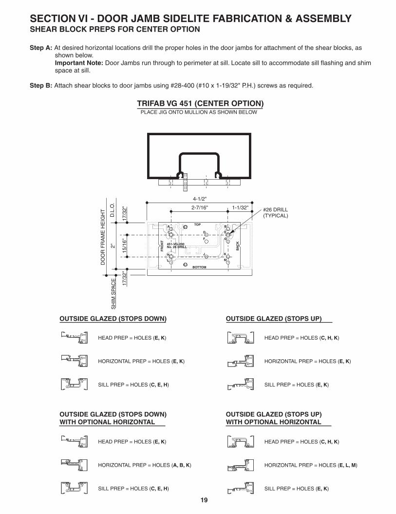
OUTSIDE GLAZED (STOPS DOWN)
OUTSIDE GLAZED (STOPS DOWN)WITH OPTIONAL HORIZONTAL
HEAD PREP = HOLES ( )E, K
HORIZONTAL PREP = HOLES ( )E, K
SILL PREP = HOLES ( )C, E, H
PLACE JIG ONTO MULLION AS SHOWN BELOW
OUTSIDE GLAZED (STOPS UP)
OUTSIDE GLAZED (STOPS UP)WITH OPTIONAL HORIZONTAL
HEAD PREP = HOLES ( )C, H, K
HORIZONTAL PREP = HOLES ( )E, K
SILL PREP = HOLES ( )E, K
HEAD PREP = HOLES ( )E, K
HORIZONTAL PREP = HOLES ( )A, B, K
SILL PREP = HOLES ( )C, E, H
HEAD PREP = HOLES ( )C, H, K
HORIZONTAL PREP = HOLES ( )E, L, M
SILL PREP = HOLES ( )E, K
1-1/32"2-7/16"
4-1/2"
KJ
L
H
BOTTOM
M
451-VG-200No. 26 DRILL
C
FR
ON
T
A
F
D
TOP
G
E
BA
CK
B
DO
OR
FR
AM
E H
EIG
HT
15/1
6"
2"D
.L.O
.
17/3
2"17
/32" #26 DRILL
(TYPICAL)
SH
IM S
PAC
E
SECTION VI - DOOR JAMB SIDELITE FABRICATION & ASSEMBLYSHEAR BLOCK PREPS FOR CENTER OPTION
Step A:
Important Note:
Step B:
At desired horizontal locations drill the proper holes in the door jambs for attachment of the shear blocks, asshown below.
Door Jambs run through to perimeter at sill. Locate sill to accommodate sill flashing and shimspace at sill.
Attach shear blocks to door jambs using #28-400 (#10 x 1-19/32" P.H.) screws as required.
20
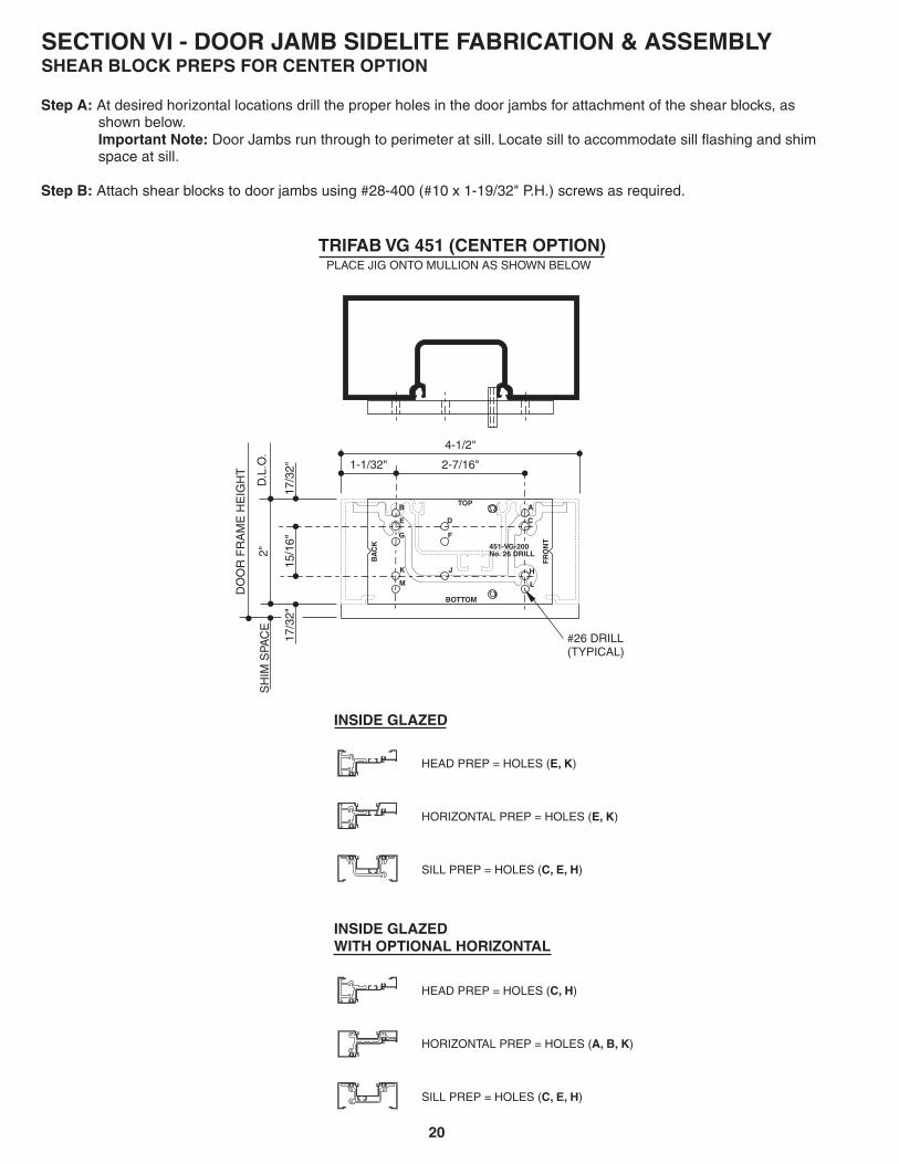
TRIFAB VG 451 (CENTER OPTION)
INSIDE GLAZED
INSIDE GLAZEDWITH OPTIONAL HORIZONTAL
HEAD PREP = HOLES ( )E, K
HORIZONTAL PREP = HOLES ( )E, K
SILL PREP = HOLES ( )C, E, H
PLACE JIG ONTO MULLION AS SHOWN BELOW
HEAD PREP = HOLES ( )C, H
HORIZONTAL PREP = HOLES ( )A, B, K
SILL PREP = HOLES ( )C, E, H
1-1/32" 2-7/16"
4-1/2"
K J
L
H
BOTTOM
M
451-VG-200No. 26 DRILL
C
FR
ON
T
A
F
D
TOP
G
E
BA
CK
B
DO
OR
FR
AM
E H
EIG
HT
15/1
6"
2"D
.L.O
.
17/3
2"17
/32"
#26 DRILL(TYPICAL)
SH
IM S
PAC
E
SECTION VI - DOOR JAMB SIDELITE FABRICATION & ASSEMBLYSHEAR BLOCK PREPS FOR CENTER OPTION
Step A:
Important Note:
Step B:
At desired horizontal locations drill the proper holes in the door jambs for attachment of the shear blocks, asshown below.
Door Jambs run through to perimeter at sill. Locate sill to accommodate sill flashing and shimspace at sill.
Attach shear blocks to door jambs using #28-400 (#10 x 1-19/32" P.H.) screws as required.

21
SECTION VI - DOOR JAMB SIDELITE FABRICATION & ASSEMBLYSHEAR BLOCK PREPS FOR CENTER OPTION
Cut horizontals to length = Daylight Opening, (Glass stops should be D.L.O. - 1/16").
Fabricate head, sill, and intermediate horizontals by drilling and countersinking for #10 F.H. screws.
Step C:
Step D:
1"
1/2"
1/2"
3-1/2"
.201" DIA. HOLE (#7 drill)
.390" DIA. x 82° COUNTERSINK(TYP.)
SILL
3/4
"
1"
HORIZONTAL
3/4
"
1"
HEAD

22
TRIFAB VG 451 (FRONT OPTION) TRIFAB VG 451 (BACK OPTION)
OUTSIDE GLAZED
INSIDE GLAZED
HEAD PREP = HOLES ( )J, K
HORIZONTAL PREP = HOLES ( )F, G
SILL PREP = HOLES ( )D, E
HEAD PREP = HOLES ( )D, E
HORIZONTAL PREP = HOLES ( )F, G
SILL PREP = HOLES ( )D, E
HEAD PREP = HOLES ( )D, E
HORIZONTAL PREP = HOLES ( )F, G
SILL PREP = HOLES ( )D, E
HEAD PREP = HOLES ( )J, K
HORIZONTAL PREP = HOLES ( )F, G
SILL PREP = HOLES ( )D, E
OUTSIDE GLAZED
INSIDE GLAZED
PLACE JIG ONTO MULLION AS SHOWN BELOW PLACE JIG ONTO MULLION AS SHOWN BELOW
2"
17/3
2"
D.L
.O.
DO
OR
FR
AM
E H
EIG
HT
4 1/2"
15/16"2-17/32"
13/1
6"
#26 DRILL(TYPICAL)
KJ
L
H
BOTTOM
M
451-VG-200No. 26 DRILL
C
FR
ON
T
A
F
D
TOP
G
E
BA
CK
B
K J
L
H
BOTTOM
M
451-VG-200No. 26 DRILL
C
FR
ON
T
A
F
D
TOP
G
E
BA
CK
B
17/3
2"
4 1/2"
15/16" 2-17/32"
2"
17/3
2"
D.L
.O.
DO
OR
FR
AM
E H
EIG
HT
13/1
6"
#26 DRILL(TYPICAL)
17/3
2"
SH
IM S
PAC
E
SECTION VI - DOOR JAMB SIDELITE FABRICATION & ASSEMBLYSHEAR BLOCK PREPS FOR FRONT or BACK OPTION
Step A:
Important Note:
Step B:
At desired horizontal locations drill the proper holes in the door jambs for attachment of the shear blocks, asshown below.
Door Jambs run through to perimeter at sill. Locate sill to accommodate sill flashing and shimspace at sill.
Attach shear blocks to door jambs using #28-400 (#10 x 1-19/32" P.H.) screws as required.
SH
IM S
PAC
E

23
1" 1"
1"1-1/2"
SECTION VI - DOOR JAMB SIDELITE FABRICATION & ASSEMBLYSHEAR BLOCK PREPS FOR FRONT OR BACK OPTIONS
Cut horizontals to length = Daylight Opening, (Glass Stops should be D.L.O. - 1/16").
Fabricate head and sill by drilling and countersinking for #10 F.H. screws.
Step C:
Step D:
.201" DIA. HOLE(#7 Drill).390" DIA. x 82° COUNTERSINK
.201" DIA. HOLE(#7 Drill)
SILL
HEAD
FRONT - INSIDE GLAZEDOR
BACK - OUTSIDE GLAZED
FRONT - OUTSIDE GLAZEDOR
BACK - INSIDE GLAZED
3/4"
1"

24
VERTICALSIDE
DOOR JAMB
HEAD
3" LONGSHIMFILLER
3" LONGSHIMFILLER
HEADSHEAR BLOCKPACKAGE
INTERMEDIATE HORIZONTALSHEAR BLOCK PACKAGE
INTERMEDIATEHORIZONTAL
SEALANTINTO REGLET
SEALANT
SEALANT
SEALANT
SEALANT
SILL
SILLSHEAR BLOCKPACKAGE
D.L.O.SIDE
NOTE:IT IS IMPORTANT THAT THE INSTALLERAPPLY SEALANT TO SHEAR BLOCKS,ENDS OF ALL HORIZONTAL MEMBERSAND GLAZING REGLETS AS SHOWNTO ENSURE GOOD SEAL. GLAZING ADAPTERSMUST ALSO BE SEALED AT THE HORIZONTALTO VERTICAL JOINT. (SEE SECTION VIII FORADDITIONAL INFORMATION.
STEP E:Install flat fillers into head, jamb and sill at perimeteranchor locations.Crimp material to prevent filler plate from sliding.Perimeter anchors should be located within 6" oneach side of vertical mullions and 24" O.C. betweenvertical mullions.
STEP D:Continue procedure above until entire frame is assembled.
STEP C:Attach horizontal members to shear blocks with fasteners provided in shear block packages.
STEP B:Apply sealant to the ends of all horizontal members, shear blocks and into reglets as shown below.
STEP A: FOR CENTER OPTION INTERMEDIATE HORIZONTALS
Vertical Mullion SideHold fabricated horizontal member in place over shear block and tight against vertical member. Then match drill tap holein shear block with #26 drill (.147") slightly offset to of countersunk hole in the horizontal so as topull the joint tight when assembled as shown below.(See Figure #1)
NOTE: FOR FRONT OR BACK INTERMEDIATE HORIZONTALSHold fabricated horizontal member in place over shear block and tight against vertical member. Then match drill tap holein horizontal with #26 drill (.147") slightly offset to of hole in the shear block so as to pull the joint tight whenassembled as shown below.(See Figure #2)
D.L.O. Side
SECTION VI - DOOR JAMB SIDELITE FABRICATION & ASSEMBLY
FIGURE #2FOR FRONT OR BACK OPTIONINTERMEDIATE HORIZONTALS
FIGURE #1FOR CENTER OPTION
INTERMEDIATE HORIZONTALS
25
SECTION VII - INSTALLATION
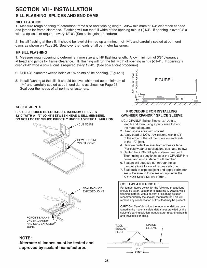
PROCEDURE FOR INSTALLINGKAWNEER XPANDR SPLICE SLEEVETM
1. Cut XPANDR Splice Sleeve (27-094) tolength and form using a putty knife to bendthe material square.
2. Clean splice area with solvent.3. Apply bead of DOW 795 silicone within 1/4"
of the edge of the sill members on each sideof the 1/2" joint.
4. Remove protective liner from adhesive tape.(For cold weather applications see Note below)
5. Center the XPANDR splice sleeve over joint.Then, using a putty knife, seat the XPANDR intocorner and onto surface of sill member.
6. Sealant will squeeze out through holes.use putty knife to tool off excess silicone.
7. Seal back of exposed joint and apply perimeterseals. Be sure to force sealant up under theXPANDR Splice Sleeve in front.
COLD WEATHER NOTE:For temperatures below 40° the following precautionsshould be taken. Just prior to installing XPANDR, wipeflashing material with a solvent or cleaning solutionrecommended by the sealant manufacturer. This willremove any condensation or frost that may be present.
: Carefully follow the recommendations con-tained in the material safety data sheet provided by thesolvent/cleaning solution manufacturer regarding healthand fire/explosion risks.
CAUTION
TOOLSEALANTFLUSH
SPLICESLEEVE
1/2"JOINT
SEAL BACK OFEXPOSED JOINT
FORCE SEALANTUNDER XPANDRAND SEAL EXPOSEDJOINT.
SPLICES SHOULD BE LOCATED A MAXIMUM OF EVERY12'-0" WITH A 1/2" JOINT BETWEEN HEAD & SILL MEMBERS.DO NOT LOCATE SPLICE DIRECTLY UNDER A VERTICAL MULLION.
CUT TO FIT
DOW CORNING795 SILICONE
SPLICE JOINTS
SILL FLASHING
HP SILL FLASHING
SILL FLASHING, SPLICES AND END DAMS
NOTE:Alternate silicones must be tested andapproved by sealant manufacturer.
1. Measure rough opening to determine frame size and flashing length. Allow minimum of 1/4" clearance at headand jambs for frame clearance. Flashing will run the full width of the opening minus (-)1/4". If opening is over 24'-0"wide a splice joint required every 12'-0". (See splice joint procedure)
2. Install flashing at the sill. It should be level,shimmed up a minimum of 1/4", and carefully sealed at both enddams as shown on Page 26. Seal over the heads of all perimeter fasteners.
1. Measure rough opening to determine frame size and HP flashing length. Allow minimum of 3/8" clearanceat head and jambs for frame clearance. HP flashing will run the full width of opening minus (-)1/4" . If opening isover 24'-0" wide a splice joint is required every 12'-0". (See splice joint procedure)
2. Drill 1/4" diameter weeps holes at 1/4 points of lite opening. (Figure 1)
3. Install flashing at the sill. It should be level, shimmed up a minimum of1/4" and carefully sealed at both end dams as shown on Page 26.Seal over the heads of all perimeter fasteners.
1/4"
DIA
.WE
EP
AT
1/4
PO
INT
S O
F D
.L.O
.
FIGURE 1

26
SECTION VII - INSTALLATIONSILL FLASHING, SPLICES AND END DAMS
STEP A:
STEP B:
STEP C:
STEP D:
Miter two 12" sections of sill flashing to correct angle.
Set mitered joint in a bed of sealant and securely anchor corner into place with a tight joint.
Completely seal non-moving mitered joint and anchors.
Use XPANDR splice sleeve at point 12" from corner.TM
12"
12"
CLOF SPLICE
C LO
F S
PLI
CE
COMPLETELY SEAL
CORNER JOINTAND ANCHORS
NON-MOVING
SECURELY ANCHORCORNER
TYPICAL 90°CORNER JOINT
12"
12"
CLOF SPLICE
C LO
F S
PLI
CE
COMPLETELY SEAL
CORNER JOINTAND ANCHORS
NON-MOVING
SECURELY ANCHORCORNER
TYPICAL 135°CORNER JOINT
NOTE:TOOL SEALANT INTOGLASS POCKETOF DOOR JAMB AT SILL
FLASHING
SEAL OVER HEADSOF FASTENERS
SEALANT
MASONRY
SEAL JUST BEFORE INSTALLATIONOF UNIT. (CONTINUOUS BEAD OFSEALANT BEHIND ALL FRAMING AT SILL)
END DAM
FLASHING
DOOR JAMB
END DAMPin End Dam to Flashing prior to installation.Seal any fastener shanks that pierce flashing.
27
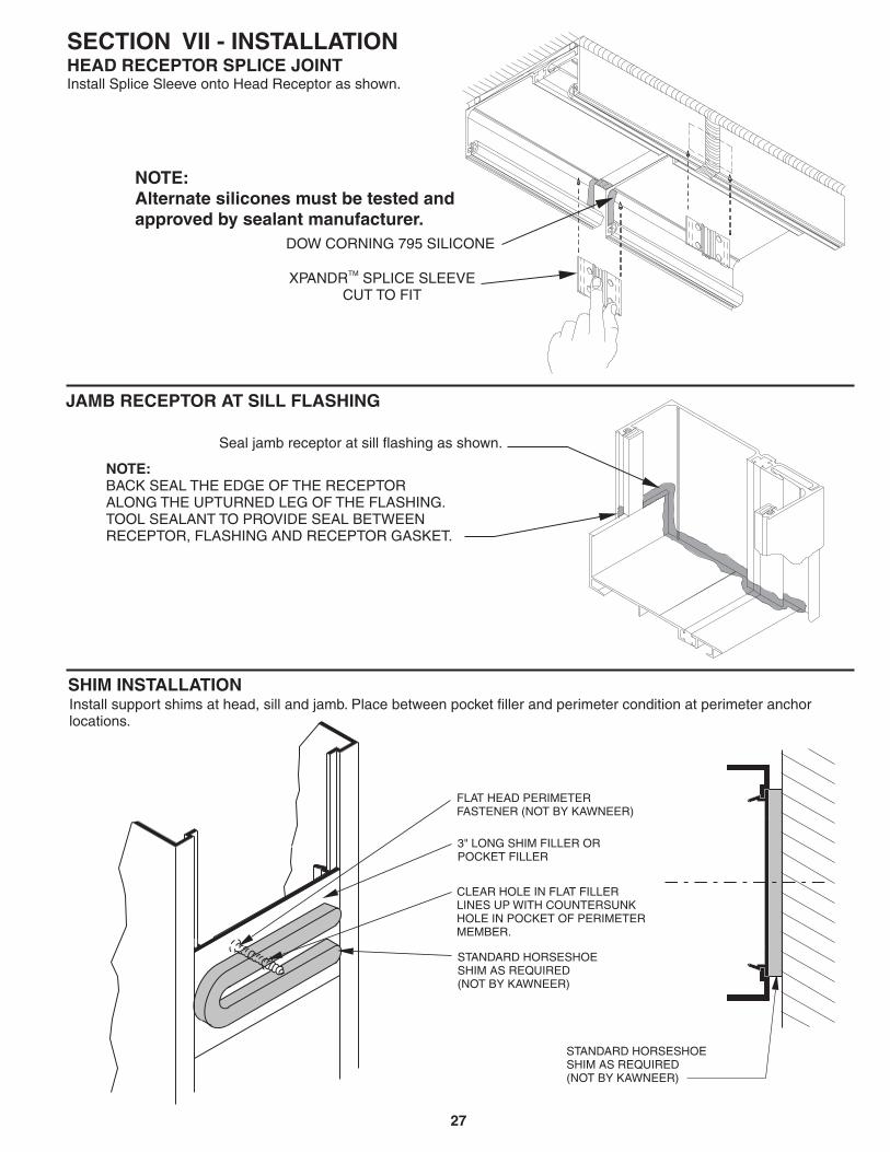
SECTION VII - INSTALLATIONHEAD RECEPTOR SPLICE JOINTInstall Splice Sleeve onto Head Receptor as shown.
JAMB RECEPTOR AT SILL FLASHING
SHIM INSTALLATIONInstall support shims at head, sill and jamb. Place between pocket filler and perimeter condition at perimeter anchorlocations.
STANDARD HORSESHOESHIM AS REQUIRED(NOT BY KAWNEER)
FLAT HEAD PERIMETERFASTENER (NOT BY KAWNEER)
3" LONG SHIM FILLER ORPOCKET FILLER
CLEAR HOLE IN FLAT FILLERLINES UP WITH COUNTERSUNKHOLE IN POCKET OF PERIMETERMEMBER.
STANDARD HORSESHOESHIM AS REQUIRED(NOT BY KAWNEER)
Seal jamb receptor at sill flashing as shown.
NOTE:BACK SEAL THE EDGE OF THE RECEPTORALONG THE UPTURNED LEG OF THE FLASHING.TOOL SEALANT TO PROVIDE SEAL BETWEENRECEPTOR, FLASHING AND RECEPTOR GASKET.
XPANDR SPLICE SLEEVECUT TO FIT
TM
DOW CORNING 795 SILICONE
NOTE:Alternate silicones must be tested andapproved by sealant manufacturer.

28
3" LONGSHIM FILLER
1
1
2
4
NOTE:DO NOT DRILL/ANCHORTHROUGH THERMALBREAK.
5
3
1
2
3
5
4
STEP 1:
STEP 2:
STEP 3: (DO NOT DRILL THROUGH THERMAL BREAK).
NOTE:
STEP 4:
Apply sealant to the upstanding leg on the flashing.
Position the assembled frame into the opening to align with sill flashing. Seat frame tightly against back leg offlashing to ensure good seal. Insert shims as needed at head and jambs, checking that the unit is level and plumb.
Drill perimeter anchor holes through glass pocket of frameAnchor holes should be located within 6" of each side of vertical mullions and 24" O.C. between.Jambs should be anchored within 6" of head and sill and 24" O.C. between. Countersink all screw heads.
Force sealant into hole for sill perimeter fastener. Coat fastener threads and shank with sealant prior to
installing. Seal over heads of fasteners at sill.
If heavy mullion or steel reinforcing is used, extra perimeter fasteners may be required to handlelarger loads. Consult Area Application Engineering Department.
Caulk both interior and exterior at head, jambs and under sill flashing with a high quality sealant.
Do not caulk between sill member and sill flashing to allow water drainage.
SECTION VII - INSTALLATIONSILL FLASHING
STEP 1: Apply sealant to the upstanding leg on the flashing.
STEP 2: Install HP interlocking sill clip into sill on each side of the vertical and crimp in place to prevent sliding.
16
HP SILL FLASHING
1
6

29
36"
1/4" MIN. TO END OF SILL
ROTATE LAST PANELINTO POSITION
FIGURE 1
SECTION VII - INSTALLATION
STEP 3: Position assembled frame onto sill tilted out at approximately 20 degrees. Allow the interlocking sill clipto engage with the lug of the flashing, and rotate to vertical position. (Figure 1)
STEP 4: Caulk both interior and exterior at head, jamb and under sill flashing with highquality sealant. Do no block weep holes in flashing.
HP SILL FLASHING
NOTE: If heavy mullion or steel reinforcing is used, extra perimeter fasteners maybe required to handle larger loads. Consult area Application Engineering.
NOTE:Last bay will NOT have451-HP-126 interlocking sill clips.
NOTE:HP flashing must extend beyond theedge of the frame by 1/4" minimum.
LAST BAY NOTE:If the last bay is less than 36" width, a largerclearance will be required at the jamb, or youmay snap it with the previous bay and installas one unit.
30
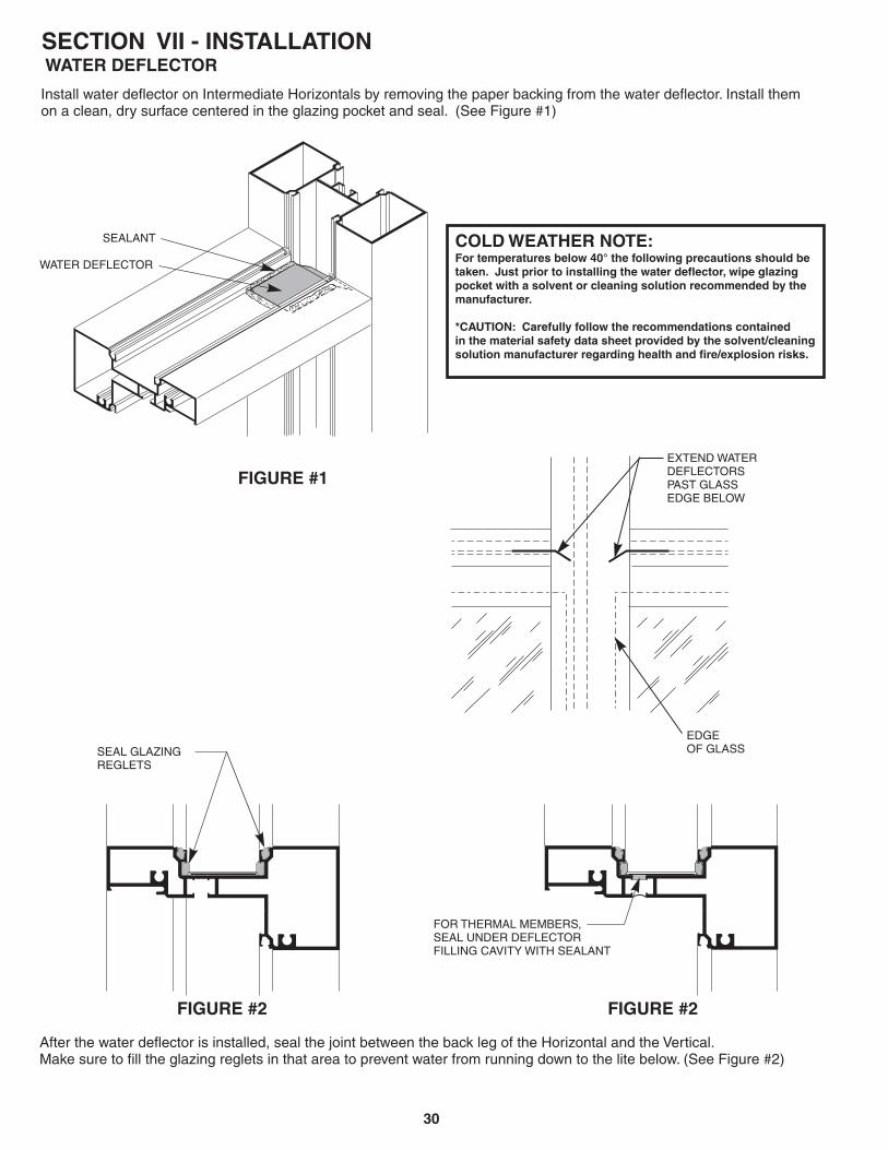
SECTION VII - INSTALLATIONWATER DEFLECTOR
Install water deflector on Intermediate Horizontals by removing the paper backing from the water deflector. Install themon a clean, dry surface centered in the glazing pocket and seal. (See Figure #1)
COLD WEATHER NOTE:For temperatures below 40° the following precautions should betaken. Just prior to installing the water deflector, wipe glazingpocket with a solvent or cleaning solution recommended by themanufacturer.
*CAUTION: Carefully follow the recommendations containedin the material safety data sheet provided by the solvent/cleaningsolution manufacturer regarding health and fire/explosion risks.
After the water deflector is installed, seal the joint between the back leg of the Horizontal and the Vertical.Make sure to fill the glazing reglets in that area to prevent water from running down to the lite below. (See Figure #2)
FIGURE #2 FIGURE #2
SEAL GLAZINGREGLETS
FIGURE #1EXTEND WATERDEFLECTORSPAST GLASSEDGE BELOW
EDGEOF GLASS
FOR THERMAL MEMBERS,SEAL UNDER DEFLECTORFILLING CAVITY WITH SEALANT
SEALANT
WATER DEFLECTOR

31
SECTION VIII - GLAZING ADAPTERSGLAZING ADAPTERS FOR TRIFAB VG 451/451TTYPICAL INSTALLATION OF PARTIAL OR FULL LENGTHVERTICAL GLAZING ADAPTERS - PRIOR TO FRAME ASSEMBLY
Vertical glazing adapters may be installed for partial, ( ) orfull-length, ( ) applications at the time the frames are assembled.
Cut VERTICAL glazing adapters to D.L.O. Plus 1/2" for partial lengthapplications or to Vertical member length for full-length applications.
Cut HORIZONTAL glazing adapters to D.L.O.
Snap vertical adapters into glazing reglets of frame and assemble frameas instructed. In partial length applications, vertical adapter should be positioned toallow sealing of the horizontal adapter to the vertical adapter (approximately 1/4"projection into horizontal pocket, ). It may be necessary to lightly crimp verticaladapter in place to prevent sliding.
When using pre-installed vertical glazing adapters, care should betaken at the time of the frame assembly, to seal the vertical glazing reglets where theymeet the intermediate horizontals. The 1/4" water deflector should also be used on allfull-length applications ( ), and installed as shown in . 1" waterdeflectors are used for partial adapter applications as long as the adapter does notimpede water evacuation of the intermediate horizontal. The water deflector mustallow water to drain into the vertical pocket the edge of the glass below.
Apply sealant to vertical adapter at the final position of the snapped-inhorizontal adapter.
Snap the HORIZONTAL glazing adapters Into the glazing reglet allowingthe adapter to rotate into the pocket and contact the sealant at the vertical adapter.
Figure 1Figure 2
STEP 1:
STEP 2:
STEP 3:
Figure 3
SPECIAL NOTE:
Figure 4 Section VII
STEP 4:
STEP 5:
beyond
INSTALLATION OF GLAZING ADAPTERS - AFTER FRAME ASSEMBLYAND FOR FIELD RETROFIT APPLICATIONS
STEP 1:
STEP 2:
Figure 5
STEP 3:
STEP 4:
Figure 3
SPECIAL CARE NOTE:
STEP 5:
STEP 6:
Cut VERTICAL glazing adapters to D.L.O. + ½".
Make a 1/4" by 1/4" notch at each end of the vertical glazing adapter.Notch should be made on the face side of the adapter nearest the gasketreglet as shown. ( )
Cut HORIZONTAL glazing adapters to D.L.O.
Snap vertical adapters into glazing reglets of frame. Adapter should bepositioned to allow sealing of horizontal adapter to the vertical adapter(aproximately 1/4" projection into horizontal pocket, )
Care should be taken to insure that the glazing adapter doesnot impede water evacuation at the intermediate horizontal. The previously installed1" water deflector must allow water to drain into the vertical pocket the edgeof the glass below.
Apply sealant to vertical adapter at the final position of the snapped-inhorizontal adapter.
Snap the HORIZONTAL glazing adapters in the glazing reglet allowingthe adapter to rotate into the pocket and contact the sealant at the vertical adapter.
beyond
1" WATERDEFLECTOR
FIGURE(1/4" over ")
11
1/4" WATERDEFLECTOR
FIGURE(1/4" over ")
21/4
ROTATEADAPTERSEALANTAT END
ADAPTERRUNSLENGTH OFVERTICAL
1/4"
1/4"
FIGURE 4
FIGURE 5
SEALANT AT END OF HORIZONTAL ADAPTER
LINE OF HORIZONTALADAPTER
1/4"
1/4"
FIGURE 3

32
1-3/
8''
5/8
''
SECTION IX - GLAZING
D.L
.O.
D.L
.O.
GLA
SS
SIZ
ED
.L.O
.+ 3
/4"
GLA
SS
SIZ
ED
.L.O
.+ 3
/4"
27-077 (HEAVY) 27-074 (STANDARD) 27-076 (LIGHT)
GLAZING CHART for 1" SYSTEM
Infill Thickness
1/8"
1/4"
3/8"
1/2"
5/8"
3/4"
7/8"
1"
1-1/8"
*Adapter
451-VG-029
451-VG-029
451-VG-029
451-VG-030
451-VG-030
451-VG-030
Weathering (Both Sides)
27-077 (Heavy)
27-077 (Heavy)
27-077 (Heavy)
27-074 (Standard)
27-074 (Standard)
27-074 (Standard)
27-076 (Light)
27-076 (Light)
27-076 (Light)
GLAZING CHART for 1/4" SYSTEM
Infill Thickness
1/8"
1/4"
3/8"
Weathering (Both Sides)
27-077 (Heavy)
27-074 (Standard)
27-076 (Light)
NOTE:27-074 27-076
27-077
For infill thickness in 1/16" increments or oversize and undersize glass,use a combination of the standard ( ) with either the light ( ) orheavy ( ) gaskets.
* NOTE:Snap-in glazing adapters 451-VG-029 and451-VG-030 are provided for applicationsrequiring infills less than 1" in thickness at adaption.Reference SECTION VIII, Glazing Adaptionfor adapter cut lengths and seal information.
NOTE: I.D. Marks = 3 for Heavy, 2 for Light, and none for Standard
GLASS SIZED.L.O + 3/4"
D.L.O.
STEP A:
STEP B:
NOTE 1:
NOTE 2:
NOTE 3:
All pockets for 1" infill are 1-3/8" in width and will accept up to 1-1/8" glass dry glazed.All pockets for 1-1/4" infill are 5/8" in width, and will accept up to 3/8" glass dry glazed.
Glass size is (Daylight Opening) D.L.O. + 3/4".
This formula does not allow for undersize or out of square daylite openings.
The glass manufacturer must indicate the specific glazing requirementsfor the material being used.
See pages 35 or 38 for Dart Corner glass sizes.

33
INSERT BETWEENGLASS AND FRAME
SIDE BLOCK INSTALLATION
One "W" Side Block should be installed into thedeep pocket of the mullion of each lite of glassin the opening.
"W" Block will expand and wedge betweenwalls of glazing pocket and prevent glass from shiftinginto deep pocket.
If deglazing of lite is required after "W" Blockis installed, remove both interior and exterior weatheringand use hook to pull "W" Block out of the pocket.
NOTE:
SECTION IX - GLAZING"W" SIDE BLOCKS
FLATTEN BLOCK & SLIDEBETWEEN REGLET ANDGLASS LITE
STRETCH
FINAL POSITION
CONTRACT
GLASS
GASKET AND GLASS STOP INSTALLATION
Step 1:
Step 4:Step 5:Step 6:
Cut horizontal and vertical gaskets to an approximate length of D.L.O. + 1/4" per foot of D.L.O..
Install glass into frame using standard flush glazing technique.Run bead of sealant along vertical reglets where glass stop meets, then install glass stop.Install horizontal and vertical gaskets into of frame in the same manner as described in Step #2.
Step 2:
Step 3:
Install gaskets on the side of frame glass stops first.
Insert gaskets into the horizontal members first starting at the ends and work toward the center as shown.(See Figure #1)Install vertical gaskets into the same side of frame after horizontal gaskets are in place in the same manner.
Position setting blocks at points under glass as required.
opposite
glass stop side
1
2
3
1
2
3
FIGURE #1
Start at ends and worktoward the center.
Vertical gasketsrun betweenhorizontal gaskets.

34
Use the same preps as are required for the standard vertical.
NOTE: Layout and cut sizes can be determined using pivot center lines.Corner parts and fabrication are the same when flipped for outside corners.
Use the same fabrication methods as are required for standard verticals. Drill (#26) and countersink 0.147 diameter holesfor assembly screws(#10 x 9/16"). Fasten together with supplied screws. Screws should be located 6" from each end and24" on center.
SECTION X - OPTIONAL CORNERSADJUSTABLE CORNERS
PIVOTED INSIDE AND OUTSIDE155° to 180° CORNERS
2.250
1.625
CL
Aluminum brakeset in sealant.
Aluminum brakeset in sealant.
NOTE: Continuous weathering installed into bothcorner halves before assembly (4) places.
Snap corners together as shownTight snaps may be waxed to make engagement easier. Corners are not designed to be unsnapped.NOTE:
SNAP CORNERS
135° CORNER
SEALANT
SEALANT90° CORNER
35
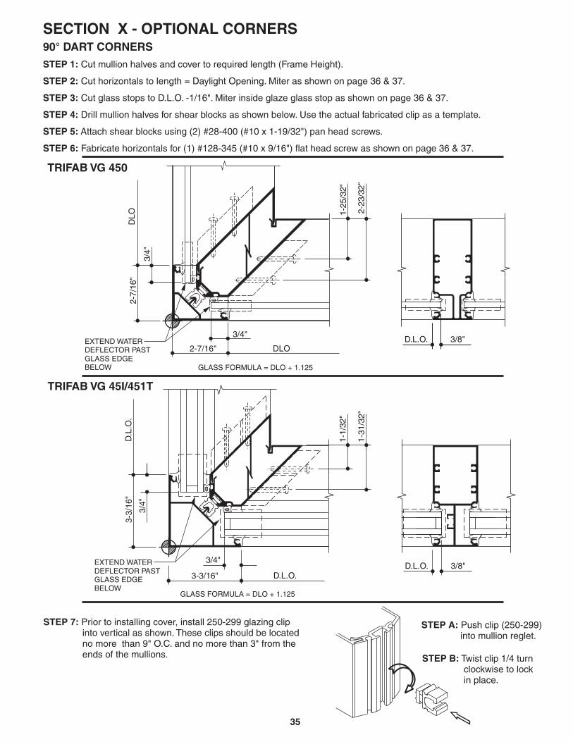
SECTION X - OPTIONAL CORNERS90° DART CORNERS
STEP 1:
STEP 2:
STEP 3:
STEP 4:
STEP 5:
STEP 6:
Cut mullion halves and cover to required length (Frame Height).
Cut horizontals to length = Daylight Opening. Miter as shown on page 36 & 37.
Cut glass stops to D.L.O. -1/16". Miter inside glaze glass stop as shown on page 36 & 37.
Drill mullion halves for shear blocks as shown below. Use the actual fabricated clip as a template.
Attach shear blocks using (2) #28-400 (#10 x 1-19/32") pan head screws.
Fabricate horizontals for (1) #128-345 (#10 x 9/16") flat head screw as shown on page 36 & 37.
STEP 7: Prior to installing cover, install 250-299 glazing clipinto vertical as shown. These clips should be locatedno more than 9" O.C. and no more than 3" from theends of the mullions.
STEP A: Push clip (250-299)into mullion reglet.
STEP B: Twist clip 1/4 turnclockwise to lockin place.
1-1/
32"
1-31
/32"
3/4"
D.L
.O.
3/4"
D.L.O.3/8"D.L.O.
GLASS FORMULA = DLO + 1.125
EXTEND WATERDEFLECTOR PASTGLASS EDGEBELOW
3-3/
16"
3-3/16"
TRIFAB VG 45I/451T
2-7/16"
3/4"
DLO
2-7/
16"
3/4"
1-25
/32"
2-23
/32"
DLO
GLASS FORMULA = DLO + 1.125
EXTEND WATERDEFLECTOR PASTGLASS EDGEBELOW
3/8"D.L.O.
TRIFAB VG 450

36
.147" DIA. HOLE(#26 DRILL)
INSIDE OR OUTSIDE GLAZED SILLCUT LENGTH = DLO
INSIDE GLAZED GLASS STOPCUT LENGTH = DLO - 1/16"
INSIDE GLAZED HEADCUT LENGTH = DLO
INSIDE GLAZED HORIZONTALCUT LENGTH = DLO
.201" DIA. HOLE (#7 DRILL)
.390" DIA. x 82° COUNTERSINK
OUTSIDE GLAZED GLASS STOPCUT LENGTH = DLO - 1/16"
OUTSIDE GLAZED HORIZONTALCUT LENGTH = DLO
OUTSIDE GLAZED HEADCUT LENGTH = DLO
.201" DIA. HOLE (#7 DRILL)
.390" DIA. x 82° COUNTERSINK
.147" DIA. HOLE(#26 DRILL)
.201" DIA. HOLE (#7 DRILL)
.390" DIA. x 82° COUNTERSINK
1/2"
45°
1"
1/2"
D.L.O.
11/16"
1"1"
45°
1/2"
15/32"
2 1/
4"
2 1/
4"
1/2"
D.L.O.
D.L.O.
11/16"
11/16"
1"1"
45°
2 1/
4"
1/2"
45°
11/16"
2 1/
4"45°
45°
D.L.O.
D.L.O. - 1/16"
D.L.O.
D.L.O. - 1/16"
1/8"
2 1/
4"
SECTION X - OPTIONAL CORNERS90° DART CORNERS FOR TRIFAB VG 450

37
17/32"
.201" DIA. HOLE (#7 DRILL)
.390" DIA. x 82° COUNTERSINK
.201" DIA. HOLE (#7 DRILL)
.390" DIA. x 82° COUNTERSINK
.201" DIA. HOLE (#7 DRILL)
.390" DIA. x 82° COUNTERSINK
.147" DIA. HOLE (#26 DRILL) .147" DIA. HOLE (#26 DRILL)
1-1/
2"
13/16" 13/16"
1-1/
2"1-
1/2"
17/32"
1-1/
2"1-
1/2"
17/32"
D.L.O. - 1/16"
1/2"
1/2"
1-3/
4"1/2"
D.L.O.
1/2"
1/2"
1-3/
4"
D.L.O.
D.L.O.
D.L.O. - 1/16"
D.L.O.
D.L.O.
5/16
"
45°
45°
45°
45°45°
45°
1-3/
4"
1-3/
4"1-
3/4"
INSIDE GLAZED HORIZONTALCUT LENGTH = D.L.O.
INSIDE GLAZED HEADCUT LENGTH = D.L.O.
OUTSIDE GLAZED HEADCUT LENGTH = D.L.O.
OUTSIDE GLAZED HORIZONTALCUT LENGTH = D.L.O.
INSIDE OR OUTSIDE GLAZED SILLCUT LENGTH = D.L.O.
INSIDE GLAZED GLASS STOPCUT LENGTH = D.L.O. - 1/16"
OUTSIDE GLAZED GLASS STOPCUT LENGTH = D.L.O. - 1/16"
SECTION X - OPTIONAL CORNERS90° DART CORNERS FOR TRIFAB VG 451/451T

38
SECTION X - OPTIONAL CORNERS135° DART CORNERS
STEP 7: Prior to installing cover, install 250-299 glazing clipinto vertical as shown. These clips should be located nomore than 9" O.C. and no more than 3" fromthe ends of the mullions.
STEP 1: Cut mullion halves and cover to required length (Frame Height).STEP 2: Cut horizontals to length = Daylight Opening. Miter as shown on page 39 & 40.STEP 3: Cut glass stops to D.L.O. -1/16". Miter inside glaze glass stop as shown on page 39 & 40.STEP 4: Drill mullion halves for shear blocks as shown below. Use the actual fabricated clip as a template.STEP 5: Attach shear blocks using (2) #28-400 (#10 x 1-19/32") pan head screws.STEP 6: Fabricate horizontals for (1) #128-345 (#10 x 9/16") flat head screw as shown on page 39 & 40.
1-1/2"
1-1/2"
3/4"
DLO
3/4"
DLO
GLASS FORMULA = DLO + 1.125
1-25
/32"
2-23
/32"
3/8"D.L.O.1-
1/32
"
1-31
/32"
3/8"D.L.O.
EXTEND WATER DEFLECTORPAST GLASS EDGE BELOW
1-13/16"
1-13/16"
3/4"
DLO
3/4"
DLO
GLASS FORMULA = DLO + 1.125
STEP A: Push clip (250-299)into mullion reglet.
STEP B: Twist clip 1/4 turnclockwise to lockin place.
TRIFAB VG 45I/451T
TRIFAB VG 450
EXTEND WATER DEFLECTORPAST GLASS EDGE BELOW

39
.147" DIA. HOLE(#26 DRILL)
INSIDE OR OUTSIDE GLAZED SILLCUT LENGTH = DLO
INSIDE GLAZED GLASS STOPCUT LENGTH = DLO - 1/16"
.201" DIA. HOLE (#7 DRILL)
.390" DIA. x 82° COUNTERSINK
INSIDE GLAZED HEADCUT LENGTH = DLO
INSIDE GLAZED HORIZONTALCUT LENGTH = DLO
OUTSIDE GLAZED GLASS STOPCUT LENGTH = DLO - 1/16"
OUTSIDE GLAZED HEADCUT LENGTH = DLO
OUTSIDE GLAZED HORIZONTALCUT LENGTH = DLO
.147" DIA. HOLE(#26 DRILL)
67.5°
D.L.O.
67.5°67.5°
1/8"
D.L.O. - 1/16" 1"
D.L.O.
D.L.O.
67.5°
1"1"
1/2"
1/2"
11/16"
2 1/
4"
D.L.O. - 1/16"
11/16"
D.L.O.
D.L.O.
67.5°
11/16"
1"
1/2"
1"
2-1/
4"
15/32"1/2"
2-1/
4"
1/2"11/16"
2-1/
4"
67.5°
SECTION X - OPTIONAL CORNERS135° DART CORNERS FOR TRIFAB VG 450
.201" DIA. HOLE (#7 DRILL)
.390" DIA. x 82° COUNTERSINK.201" DIA. HOLE (#7 DRILL).390" DIA. x 82° COUNTERSINK

40
INSIDE OR OUTSIDE GLAZED SILLCUT LENGTH = D.L.O.
INSIDE GLAZED GLASS STOPCUT LENGTH = D.L.O. - 1/16"
INSIDE GLAZED HORIZONTALCUT LENGTH = D.L.O.
OUTSIDE GLAZED GLASS STOPCUT LENGTH = D.L.O. - 1/16"
OUTSIDE GLAZED HORIZONTALCUT LENGTH = D.L.O.
OUTSIDE GLAZED HEADCUT LENGTH = D.L.O.
INSIDE GLAZED HEADCUT LENGTH = D.L.O.
17/32"
13/16"13/16"
17/32"17/32"
1-1/
2"
1-1/
2"
1-1/
2"
1-1/
2"1-
1/2"
1/2"
1-3/
4"
1-3/
4"
D.L.O.
1/2"
1-3/
4"
1/2"
1/2"
1-3/
4"
1/2"
D.L.O.
1-3/
4"
D.L.O.
D.L.O. - 1/16"
D.L.O.
D.L.O. - 1/16"
5/16
"
D.L.O.
67.5°
67.5°
67.5°
67.5°
67.5°
67.5°
SECTION X - OPTIONAL CORNERS135° DART CORNERS FOR TRIFAB VG 451/451T
.201" DIA. HOLE (#7 DRILL)
.390" DIA. x 82° COUNTERSINK
.147" DIA. HOLE (#26 drill)
.201" DIA. HOLE (#7 DRILL)
.390" DIA. x 82° COUNTERSINK
.147" DIA. HOLE (#26 drill)
.201" DIA. HOLE (#7 DRILL)
.390" DIA. x 82° COUNTERSINK

41
SECTION XI - EXPANSION MULLION
SECTION XII - STEEL REINFORCING
An Expansion Mullion is to be used every 20' in large openings, regardless of the method of construction.The dimension of the assembly should be adjusted based on the temperature at the time of assembly and expectedhigh and low service temperatures use reference dimension. (For example, the sight line will be reduced slightly wheninstalled in hot weather and increased slightly when installed in cold weather).
2-1/8"
SPLIT MULLION WITHSTEEL REINFORCING450-110
Steel reinforcement should run the full length of the mullion and be shimmed or fastened into place to prevent movementof the steel in the mullion. The cut ends of the steel reinforcing must be coated with a corrosion-inhibiting primer beforeinstallation.
For Trifab VG 451 center plane applications, when steel reinforcing is required, the non-thermal split mullionthermal pockets must be used.
NOTE:without
REFERENCEDIMENSION
1-7/8"
REFERENCEDIMENSION

42
SEAL CHANNELTO MULLION
SEAL MULLION TOFINISHED FLOOR
COMPLETELY SEAL BOTTOMOF MULLION POCKET TO FLOORAND TO CHANNEL.
TOP VIEW
1-3/8"
DRILL WITH #26 DRILLAND COUNTERSINKUSE SCREWCENTERED IN POCKET.
128-345
SEAL INTERIORGLASS STOPCONTINUOUSLYACROSS OPENINGAND TO VERTICALAT ENDS.
DRILL THROUGH SPLINESOF CLIP WITH #26 DRILL INTOPOCKET OF VERTICAL. SECURECLIP TO VERTICAL WITH(2) (# #10 x 2-5/8" P.H.SCREWS, CLIP IS CENTEREDIN POCKET.
128-354)
128-345 SCREWSAT SETTINGBLOCK POINTS.
1/4" WEEP HOLEAT 1/4 POINTS OFCHANNEL (TYP.)
SET IN BEDOF SEALANT
ANCHOR TOMASONRY
5-3/
4" M
AX
.-
4-1/
4" M
IN.
8-3/
8" M
AX
. -
7-1/
8" M
IN.
NOTE:When using the sidelite base on both sides of themullion, a clip is required in each pocket of the vertical.One of the clips must be the reversed as shown toavoid interference of the screws.
Top of Sidelite Base
SEAL OVER HEADSOF PERIMETERFASTENERS
SECTION XIII - ADJUSTABLE NARROW SIDELITE BASEFOR CENTER GLAZED OPTION USING THE NON-THERMAL, 2-PIECE VERTICAL ONLY
Determine height of Sidelite Base.Common bottom door rail heights are shown below.
STANDARD BASE
TALL BASE
190 Door w/ Threshold ----------- 5-1/16"190 Door w/o Threshold --------- 4-9/16"
350 & 500 Door w/ Threshold --------- 7-11/16"350 & 500 Door w/o Threshold ------- 7-3/16"
NOTE:Project windloads may produce end load reactions at the vertical mullionsthat may require additional anchors. Consult Application Engineering forreview of narrow sidelite base applications.
7/8"
1"
1-3/
8"1"

43
SECTION XIII - HIGH SIDELITE BASE OR HORIZONTALFOR CENTER GLAZED OPTION
PERIMETERFASTENER(NOT BY KAWNEER)
SPLINESCREWS
SEAL END OF SIDELITE BASEAND INTERIOR GLASS STOPAT VERTICALS
SEAL END OFSIDELITE BASEAT VERTICALS
MATCH DRILL HOLESCENTERED IN REGLETS
SEAL INTERIOR GLASS STOPCONTINUOUS ACROSS OPENING& TO VERTICALS AT ENDS. *INSTALL FILLER
6" FROM JAMB & 24" O.C.
FLASHING
SEAL FLASHINGACROSS BACK LEG
SEAL FLASHINGACROSS BACK LEG
1"
4-11
/16"
1-13
/32"
1-1/
4"
2-7/16"
APPLY SEALANT TOEND OF SIDELITE BASEAND INTERIOR GLASS STOP
SEAL OVER HEADSOF PERIMETER FASTENERS
SCREW SPLINECENTER OPTION ONLY
2-1/
32"

44
KAWNEER COMPANY, INC.TECHNOLOGY PARK/ATLANTA555 GUTHRIDGE COURTNORCROSS, GEORGIA 30092