instructions for use us - quang Đứcus).pdf · interacoustics will make available on request...
TRANSCRIPT

Item No. 8106887 – ver. 03/2015
Instructions for Use – US
AT235 Impedance Audiometer


Table of Contents
1 Introduction .......................................................................................................... 1 1.1 About this Manual ............................................................................................... 1 1.2 Intended Use ....................................................................................................... 1 1.3 Contraindications for performing impedance audiometry ..................................... 1 1.4 Product description.............................................................................................. 2 1.5 About warnings and cautions .............................................................................. 3
2 Unpacking and Installation .................................................................................. 5 2.1 Unpacking and Inspection ................................................................................... 5 2.2 Markings ............................................................................................................. 6 2.3 Important safety instructions ................................................................................ 7 2.4 Connections ........................................................................................................ 9 2.5 Calibration cavities .............................................................................................. 9 2.6 Changing probe system .................................................................................... 10 2.7 Safety Precautions to take when connecting the AT235. ................................... 11 2.8 License .............................................................................................................. 12
3 Operating Instructions ....................................................................................... 13 3.1 Handling and selection of ear tips ...................................................................... 14 3.2 Switching the AT235 on and off ......................................................................... 14 3.3 Probe Status ..................................................................................................... 15 3.4 Use of standard and clinical probe system ........................................................ 16 3.5 AT235 Stand-alone operation ............................................................................ 16
3.5.1 AT235 Stand-alone operation panel ......................................................... 16 3.5.2 Startup ..................................................................................................... 17 3.5.3 Instrument settings – language, printer, date & time, etc. ......................... 18 3.5.4 Test and module selection ....................................................................... 19 3.5.5 Tympanometry test screens ..................................................................... 19 3.5.6 Audiometry test screen ............................................................................. 24 3.5.7 Start and stop of a tympanometric test ..................................................... 25 3.5.8 Save ......................................................................................................... 26 3.5.9 View historical sessions ........................................................................... 27
3.6 Operating in PC Controlled Mode (only available with Diagnostic Suite) ........... 28 3.6.1 PC Power Configuration ........................................................................... 28 3.6.2 Starting from OtoAccess™ ....................................................................... 28 3.6.3 Starting from Noah 4 ................................................................................ 29 3.6.4 Crash Report ............................................................................................ 29 3.6.1 Instrument setup ...................................................................................... 30 3.6.2 Using IMP ................................................................................................ 31 3.6.3 Using AUD ............................................................................................... 33 3.6.4 SYNC Mode ............................................................................................. 35 3.6.5 The Sync Tab ........................................................................................... 35 3.6.6 Client Upload ........................................................................................... 36 3.6.7 Session download .................................................................................... 36
4 Maintenance ....................................................................................................... 39 4.1 General Maintenance Procedures ..................................................................... 39 4.2 General Maintenance Procedures ..................................................................... 40 4.3 Cleaning the Probe Tip ...................................................................................... 41 4.4 Concerning Repair ............................................................................................ 42 4.5 Warranty ........................................................................................................... 42 4.6 Periodic calibration ............................................................................................ 43
5 Specifications ..................................................................................................... 45 5.1 AT235 Technical Specifications......................................................................... 45 5.2 Electromagnetic Compatibility (EMC) ................................................................ 54

AT235 Instructions for Use - US Page 1
1 Introduction
1.1 About this Manual
This manual is valid for the AT235 (Model 1077).
The product is manufactured by: Interacoustics A/S Drejervænget 8 DK 5610 Assens Denmark Tel.: +45 6371 3555 Fax: +45 6371 3522 E-mail: [email protected] Web: www.interacoustics.com
1.2 Intended Use
The AT235 is an automatic impedance audiometer with built-in screening audiometry suited for screening, as well as diagnostic work. Neonatal screening programs will particularly appreciate the presence of high probe tone tympanometry, allowing more reliable tympanometric results in neonates.
The AT235 tympanometer is intended to be used by an audiologist, hearing healthcare professional, or trained technician in a quiet environment.
1.3 Contraindications for performing impedance audiometry
Recent stapedectomy or other middle ear surgery Discharging ear Acute external auditory canal trauma Discomfort (eg severe otitis externa) Occlusion of the external auditory canal Presence of tinnitus, hyperacusis or other sensitivity to loud sounds may contraindicate testing when
high intensity stimuli are used
Testing should not be performed on patients with such symptoms without a medical doctor’s approval.
Visual inspection for obvious structural abnormalities of the external ear structure and positioning as well as the external ear canal should be performed before testing.

AT235 Instructions for Use – US Page 2
1.4 Product description
The AT235 consist of the following parts:
Included Parts
AT235 instrument
Clinical Probe System1
Diagnostic Probe System1
Power supply unit UE60
Contralateral headphone1
Audiometric Headset1
CAT50
Patient Response1
Printer kit (Options)
Wall mounting kit (Options)
Cleaning cloth
Assortment bag BET55
1 Applied part as according to IEC60601-1

AT235 Instructions for Use – US Page 3
1.5 About warnings and cautions
Throughout this manual the following meaning of warnings, cautions and notices are used:
WARNING indicates a hazardous situation which, if not avoided, could result in death or serious injury.
CAUTION, used with the safety alert symbol, indicates a hazardous situation which, if not avoided, could result in minor or moderate injury.
NOTICE is used to address practices not related to personal injury.

AT235 Instructions for Use – US Page 4

AT235 Instructions for Use – US Page 5
2 Unpacking and Installation
2.1 Unpacking and Inspection
Check box and contents for damage
When the instrument is received please check the shipping box for rough handling and damage. If the box is damaged it should be kept until the contents of the shipment have been checked mechanically and electrically. If the instrument is faulty please contact your local distributor. Keep the shipping material for the carrier’s inspection and insurance claim.
Keep carton for future shipment
AT235 comes in its own shipping carton, which is specially designed for the AT235. Please keep this carton. It will be needed if the instrument has to be returned for service.
If service is required please contact your local distributor.
Reporting Imperfections
Inspect before connection Prior to connecting the product it should once more be inspected for damage. All of the cabinet and the accessories should be checked visually for scratches and missing parts.
Report immediately any faults
Any missing part or malfunction should be reported immediately to the supplier of the instrument together with the invoice, serial number, and a detailed report of the problem. In the back of this manual you will find a "Return Report" where you can describe the problem.
Please use the "Return Report"
Use of the return report provides the service engineer with the relevant information to investigate the reported issue. Without this information, there may be difficulty in determining the fault and repairing the device. Please always return the device with a completed Return Report in order to guarantee that correction of the problem will be to your satisfaction.
Use only specified power supply unit UE60 type

AT235 Instructions for Use – US Page 6
2.2 Markings
The following markings can be found on the instrument:
Symbol Explanation
Type B applied parts.
Patient applied parts that are not conductive and can be immediately released from the patient.
Refer to instruction manual
WEEE (EU-directive)
This symbol indicates that when the end-user wishes to discard this product, it must be sent to separate collection facilities for recovery and recycling.
0123
The CE-mark indicates that Interacoustics A/S meets the requirements of Annex II of the Medical Device Directive 93/42/EEC. TÜV Product Service, Identification No. 0123, has approved the quality system.
Year of manufacture
Do not re-use Parts like ear-tips and similar are for single use only
Display Port Connection – HDMI type
“ON” / “OFF” (push-push)

AT235 Instructions for Use – US Page 7
2.3 Important safety instructions Read this instruction manual carefully and completely before using the product
1. External equipment intended for connection to signal input, signal output or other connectors shall comply with relevant IEC standard (e.g. IEC 60950 for IT equipment). In these situations an optical isolator is recommended to fulfill the requirements. Equipment not complying with IEC 60601-1 shall be kept outside the patient environment, as defined in the standard (usually 1.5 meter). If in doubt, contact qualified medical technician or your local representative.
2. This instrument does not incorporate any separation devices at connections for PC’s, printers, active speakers etc. (Medical Electrical System). A galvanic l isolator is recommended to fulfill the requirements. For safe setup please refer to section 2.3.
3. When the instrument is connected to a PC and other items of equipment of a medical electrical system
pleae ensure that the total leakage current cannot exceed the safety limits and that separations have the dielectric strength, creepage clearances and air clearances required fulfilling the requirements of IEC/ES 60601-1. When the instrument is connected to a PC and other similar items be aware of not touching the PC and patient simultaneously.
4. To avoid the risk of electric shock, this equipment must only be connected to supply mains with protective earth.
5. Do not use any additional multiple socket-outlet or extension cord. For safe setup please refer to section
2.3
6. This instrument contains a coin-type lithium battery. The cell can only be changed by service personnel. Batteries may explode or cause burns, if disassembled, crushed or exposed to fire or high temperatures. Do not short-circuit.
7. No modification of this equipment is allowed without Interacoustics authorization.
8. Interacoustics will make available on request circuit diagrams, component part lists, descriptions,
calibration instructions, or other information that will assist service personnel to repair those parts of this audiometer that are designated by the Interacoustics as repairable by service personnel.
9. For maximum electrical safety, turn off the power from a mains powered instrument when it is left
unused.
10. The instrument is not protected against harmful ingress of water or other liquids. If any spillage occurs check the instrument carefully before use or return for service.
11. No part of the equipment can be services or maintained while in use with the patient.

AT235 Instructions for Use – US Page 8
1. Never insert or in any way use the insert headset without a new clean non defect test tip. Always make sure that foam or ear-tip is mounted correctly. Ear tips and foam are single use.
2. The instrument is not intended to be used in environments exposed to fluid spills.
3. The instrument is not intended to be used in oxygen rich environments or use in conjunction with flammable agents.
4. Check calibration if any parts of the equipment is exposed to shock or rough handling.
1. To prevent system faults take appropriate precautions to avoid PC viruses and similar.
2. Use only transducers calibrated with actual instrument. To identify a valid calibration, the serial number for the instrument will be marked on the transducer.
3. Although the instrument fulfils the relevant EMC requirements precautions should be taken to avoid
unnecessary exposure to electromagnetic fields, e.g. from mobile phones etc. If the device is used adjacent to other equipment it must be observed that no mutual disturbance appears. Please also refer to EMC considerations in section 5.2
4. Use of accessories, transducers and cables other than specified, with the exception of transducers and cables sold by Interacoustics or representatives may result in increased emission or decreased immunity of the equipment. For list of accessories, transducers and cables that fulfils the requirements please refer to section 5.2
5. Within the European Union it is illegal to dispose electric and electronic waste as unsorted municipal
waste. Electric and electronic waste may contain hazardous substances and therefore has to be collected separately. Such products will be marked with the crossed-out wheeled bin shown below. The cooperation of the user is important in order to ensure a high level of reuse and recycling of electric and electronic waste. Failing to recycle such waste products in an appropriate way may endanger the environment and consequently the health of human beings.
6. Outside the European Union, local regulations should be followed when disposing of the product after its
useful life.

AT235 Instructions for Use – US Page 9
2.4 Connections
1 Probe Dedicated probe connection
2 LAN LAN (Not used)
3 USB B For PC connection
4 USB A For printer, mouse, keyboard, Memory stick
5 HDMI For external monitor or projector
6
In 24 V
Use only specified power supply unit UE60 type
7 Trigger in / out Cochlear implant trigger option
8 Pat. Resp. Patient response button
9 Right Audiometry Right output
10 Left Audiometry Left output
11 Contra Contra transducer output
2.5 Calibration cavities
You can use the 0.2 ml, 0.5 ml, 2.0ml and 5 ml for validity check of the probe calibration.
To perform a calibration check, select a protocol the measures a tympanogram.
Do not use an ear tip! Place the probe tip completely into the cavity. Perform the measurement. Check the volume that was measured.
The allowed tolerance in the volume measurement is ±0.1 ml for cavities up to 2 ml and ±5% for larger cavities. These tolerances are applicable for all probe tone frequencies.
We strongly recommend calibrating probe and contra phone at least once a year.

AT235 Instructions for Use – US Page 10
2.6 Changing probe system
Change between the standard and clinical probe as follows:
1. Locate the probe connection on the back of the unit.
2. Open the 2 locks by pushing them to the sides.
3. Swap to the other probe system.
4. Close the 2 locks by pushing them to the centre.

AT235 Instructions for Use – US Page 11
2.7 Safety Precautions to take when connecting the AT235.
Please note that if connections are made to standard equipment like printers and networks, special precautions must be taken in order to maintain medical safety.
Please follow instructions below.
Fig 1. AT235 used with the medically approved power supply UE60.
Fig. 2. AT235 used with, a medically approved safety transformer and a wired connection to a PC.
Mains outletMedical power supply
AT235 alone
AT235Medical power supply
Mains outlet
Medically approved safety transformer
PC power supply
PC
Printer

AT235 Instructions for Use – US Page 12
Fig. 3. AT235 used with the medically approved power supply UE60 and printout with MPT-III printer.
The separable mains plug is used to safely disconnect mains from the device. Do not position the power supply in a position so that it is difficult to disconnect the device.
2.8 License
When you receive the AT 235 it already contains the license you have ordered. If you would like to add licenses that are available in AT235, please contact your dealer for a license.
Mains outletMedical power supply
AT235 alone
MPT-III printerFully charged,
WITHOUT POWER SUPPLY CONNECTED

AT235 Instructions for Use – US Page 13
3 Operating Instructions
The instrument is switched on by pressing the ON button on the unit. When operating the instrument, please observe the following general precautions:
1. Use this device only as described in this manual. 2. Use only the disposable Sanibel ear tips designed for use with this instrument. 3. Always use a new ear tip for each patient to avoid cross-contamination. The ear tip is not designed
for reuse. 4. Never insert the probe tip into the ear canal without affixing an ear tip as omission may damage the
patient’s ear canal. 5. Keep the box of ear tips outside the reach of the patient. 6. Be sure to insert the probe tip in a way which will ensure an airtight fit without causing any harm to
the patient. Use of a correct and clean ear tip is mandatory. 7. Be sure to use only stimulation intensities acceptable to the patient. 8. When presenting contralateral stimuli using the insert phones – do not insert the phones or in any
way try to conduct measurements, without a correct insert ear tip in place. 9. Clean the headphone cushion regularly using a recognized disinfectant. 10. Contraindications to testing include recent stapedectomy or middle ear surgery, a discharging ear,
acute external auditory canal trauma, discomfort (e.g, severe otitis externa) or occlusion of the external auditory canal. Testing should not be performed on patients with such symptoms without a medical doctor’s approval.
11. The presence of tinnitus, hyperacusis or other sensitivity to loud sounds may contraindicate testing when high intensity stimuli are used.
1. Careful handling of the instrument whenever in contact with a patient should be given high priority. Calm and stable positioning while testing is preferred for optimal accuracy.
2. The AT235 should be operated in a quiet environment, so that measurements are not influenced by outside acoustic noises. This may be determined by an appropriately skilled person trained in acoustics. ISO 8253 Section 11, defines a quiet room for audiometric hearing testing in its guideline.
3. It is recommended that the instrument be operated within an ambient temperature range of 15°C / 59°F – 35°C / 95°F.
4. The headphone and insert phone are calibrated to the AT235 – introducing transducers from other equipment requires a re-calibration.
5. Never clean the transducer housing with water or insert non-specified instruments into the transducer.
6. Do not drop and avoid other undue impact to this device. If the instrument is dropped or otherwise damaged, return it to the manufacturer for repair and/or calibration. Do not use the instrument if any damage is suspected.
7. Although the instrument fulfils the relevant EMC requirements, precautions should be taken to avoid unnecessary exposure to electromagnetic fields, e.g. from mobile phones etc. If the device is used adjacent to other equipment, caution must be taken to observe that no mutual disturbance appears.

AT235 Instructions for Use – US Page 14
3.1 Handling and selection of ear tips
When using the AT235 probe and CIR55 contra phone, Sanibel ear tips must be used.
The Sanibel ear tips are single use only and should not be reused. Reuse of ear tips can lead to the spread of infection from patient to patient.
The probe and CIR55 contra phone must be fitted with an ear tip of a suitable type and size before testing. Your choice will depend on the size and shape of the ear canal and ear. Your choice may 7also depend on personal preference and the way you perform your test.
When performing a quick impedance screening test you may choose an umbrella shaped ear tip. Umbrella ear tips seal the ear canal without the probe tip going into the ear canal. Press the ear tip firmly against the ear canal in such a way that a seal remains during the complete test.
For more stable testing, we recommend using an extension cord with a mushroom shaped ear tip. Make sure that this ear tip inserts completely into the ear canal. Mushroom shaped ear tips allow you to test ‘hands free’ from the AT235. This reduces the chance of contact noise disturbing the measurement.
Refer to the “Selecting the Correct Ear Tip” Quick Guide included in the AT235 Additional Information document for an overview of ear tip sizes and selection.
3.2 Switching the AT235 on and off
Switch the AT235 on or off by pressing the ON (1).
The AT235 takes approximately 45 seconds to boot up. Allow the unit to warm up for 1 minute before use.
2
2

AT235 Instructions for Use – US Page 15
3.3 Probe Status
The probe status is indicated by the color of the light on the control panel, standard probe system and the clinical probe system. Below, the colors and their meanings are explained:
Color Control panel Standard probe Clinical probe Status
Red
Right ear is selected. Probe is out of the ear.
Blue
Left ear is selected. Probe is out of the ear.
Green
Probe is in the ear and a seal is maintained.
Yellow
Probe is in the ear and is blocked, leaking or too noisy.
White
The probe has just been attached. Probe status is unknown. If the probe light stays white in any other situation the AT235 may need to be switched off and back on again to regain proper probe status.
Blinking AT235 is pausing and/or an interaction is expected. The AT235 will for example remain blinking green if the protocol has finished testing and the probe is still in the ear. The user may pause the AT235 before inserting the probe resulting in blue or red blinking.
No light AT235 is not monitoring the probe status.

AT235 Instructions for Use – US Page 16
3.4 Use of standard and clinical probe system
For establishing most stable measurements it is recommended not to hold the probe between fingers during the measurements. Particularly acoustic reflex measurements could be affected by probe movements.
3.5 AT235 Stand-alone operation
3.5.1 AT235 Stand-alone operation panel
Name Description
1 ON Turns the AT235 ON and OFF.
2 Shift Shift is used to access secondary functions of the other keys.
3 Setup Hold down Setup and use the wheel (19) to select the desired Setup menu then let go of the Setup button to open it.
4-13 Function keys The 10 function keys hold functions of which labels are displayed in the screen.
14 Tests Hold down Test and use the wheel (19) to select the desired protocol or audiometry or impedance module. Let go of the Test button to make your selection.
15 New Session Clears data and starts a new session in the current module.
16 Clients Press the Clients button to open a window in which a client can be selected, edited or created. Also its historic sessions can be viewed.
17 Save Saves the current session for the current module.
18 Print Prints the session that is currently on screen.
19 Wheel Used for manual pump control as well as scrolling through menus and selection possibilities. In the audiometry module the wheel controls the stimulus intensity.
20 Tymp Selects or deselects a tympanogram test from the protocol.

AT235 Instructions for Use – US Page 17
21 Reflex Selects or deselects a reflex test from the protocol. If necessary a test with ipsilateral or contralateral reflexes is automatically added to the protocol.
22 Tone Switch, Enter, Start/stop
In audiometry it is the tone switch. In tympanometry it interrupts or starts the auto-start function and it operates as a stop and start button while the probe is in an ear. In menus that require textual input the tone switch is used for making selections.
23 Right Selects right ear for testing.
24 Left Selects left ear for testing.
3.5.2 Startup
The AT235 will always load the last used tympanometry protocol as a starting point.

AT235 Instructions for Use – US Page 18
3.5.3 Instrument settings – language, printer, date & time, etc.
While holding down the “Setup” button (3), use the wheel (19) for selecting Instrument settings and release the “Setup” button (3) to open it.
For changing the operation language of the system hold the Language button (6) while using the wheel (19) to selecting the language of your choice. The AT235 needs to be restarted for the change to be effectuated.
Use the wheel (19) to preselect Display light (A), LED light (B), Date and time (C) and Printer type (D). In order to make changes at Display light, LED light and the Printer type, hold the Change button (7) while rotating the wheel (19).
In case the AT235 is connected to the Diagnostic Suite, your PC will automatically update date and time.

AT235 Instructions for Use – US Page 19
Manually updating date and time is done by pressing the Change button (7) when Date and time (C) is preselected. This gives access to the screen below. Use the wheel (19) to select day, month, year, hour or minutes. Use the Change - and Change + buttons (9 and 10) to adjust the number. Press the Set button (13) to keep changes and set date and time or press the Back button (12) to reject any change made.
3.5.4 Test and module selection
While holding the “Tests” button (14), use the wheel (19) for selecting either one of the protocols or a different module. Release the wheel (19) for making your selection.
3.5.5 Tympanometry test screens
After startup the AT235 will have selected the last used impedance protocol and will be ready to start a test. The screen now shown we refer to as the test screen. The following paragraphs describe which information and functionalities are found on the tympanogram, reflex and audiometry test screens.

AT235 Instructions for Use – US Page 20
3.5.5.1 Tymp test screen
A Probe status showing the color corresponding to the probe light as
described in paragraph 3.3. It shows the labels: in ear, out of ear, leaking or blocked
B Probe tone frequency.
C The current pressure is indicated in daPa.
D The open triangle shows the current pressure. The solid triangle (in manual mode (O) only) shows the target pressure.
E The name of the current protocol.
F Protocol list showing which test is currently viewed and in the check boxes which tests will be tested after starting a test.
G Press Prev. Test to select the previous test of the protocol list.
H Press Next Test to select the next test of the protocol list.
I Press Include to select or Exclude to deselect the checkbox of the currently viewed test (F) and thereby include or exclude it from testing.
J When several measurement attempts were done, pressing Data allows
choosing which data set is being viewed. Only the viewed data can be saved to a client.

AT235 Instructions for Use – US Page 21
K Pressing Scale allows changing the scale of the compliance axis in the
tympanogram.
L Pressing Compensated allows activating or deactivating the compensation
of the tympanogram according to the estimated ear canal volume.
M Pressing Ygb allows toggling between viewing the so called Y, B or G
tympanogram. The one shown currently shown is recognized by the capital in the button label.
N Pressing 0 daPa results in quickly setting ambient pressure as target
pressure and quickly pumping back to 0 daPa. The function is only available in manual mode (O).
O Activating manual mode in the tympanogram test allows setting the pressure manually with the wheel (19). Press the attenuator (22) to start and stop recording in manual mode. Switching manual mode off and returning to automatic testing is done by pressing Auto

AT235 Instructions for Use – US Page 22
3.5.5.2 Reflex test screen
O Activating manual mode in the reflex test allows single reflex measurements at a time and optionally the pressure at which the reflex is measured can be manually set (see T).
P The level is showing the reflex activator intensity of the currently selected reflex measurement (Q).
Q The pressure slider gives an indication for at which pressure reflex measurements are set to be tested (in manual mode (O) only). The slider is moved by holding the pressure button (see T) and turning the wheel.
R The compliance meter shows an indication for the current non compensated compliance value and might be uses as a help to set the pressure at peak pressure or at an offset from peak pressure (in manual mode (O) only).
S The currently selected reflex measurement is indicated by the rectangle around it. Within the reflex graph also the numerical deflection value is displayed.
T Pressing pressure allows setting the pressure manually (see Q) (in manual mode
(O) only).
U Pressing the arrow up button moves the reflex selection to the previous reflex
row. Moving the selection sideways is done with the wheel (19).
V Pressing the arrow down button moves the reflex selection to the next reflex row.
Moving the selection sideways is done with the wheel (19).
W In manual mode (O) the Add Stimulus button is available and allows adding new
reflex rows.

AT235 Instructions for Use – US Page 23
X In manual mode (O) the Add Level button is available and allows including
additional test intensities.
Pressing Change Status toggles the status of the currently selected reflex (Q).
Green indicates that a reflex is present while red/blue indicates that the reflex is not present.
Holding the Enlarge button show the currently selected reflex (Q) in highest available detail.

AT235 Instructions for Use – US Page 24
3.5.6 Audiometry test screen
A Use the tone switch (22) to present a sound to the client. The stimulus area will
light up when a sound is being presented.
B This visualizes the dial setting of the stimulus intensity which can be changed by rotating the wheel (19).
C The measurement type (HL, MCL, UCL or Tinnitus is shown) as well as the presentation type (tone or pediatric noise) and the test frequency is shown.
D For clarity second channel information is shown, although the AT235 cannot contain licenses to use this second channel.
E The cursor in the audiogram visualized the currently selected stimulus frequency and intensity.
F Press the “1,2,5 dB” button (4) to toggle the dB step size. The current step size is
indicated on the label of this button.
G Hold down the “Meas.type” button (5) and use the wheel (19) to select the
measurement type.
H Press the “Magnify” button (6) to increase the intensity and frequency labels (B, C
and D).

AT235 Instructions for Use – US Page 25
I Press the “Store” button (8) for storing points in the audiogram.
J Press the “No Resp” button (9) for storing a no response indication in the
audiogram.
K Press the “Delete Curve” button (10) for deleting the curve of the current
measurement type.
L Press the “Ext Range” button (11) to activate the maximum intensity range of the
transducer.
M Press the “Freq -“ button (12) to lower the test frequency.
N Press the “Freq +“ button (13) to increase the test frequency.
3.5.7 Start and stop of a tympanometric test
After startup the AT235 is ready to automatically start a measurement as soon as it detects that the probe is in the ear. When the probe is in the ear the test can be manually stopped (or paused) and again started by pressing the “Start/stop” button (22) or by pressing the probe button. When the probe is out of the ear the test can be stopped (as if it is paused before inserting the probe) or started by pressing the “Start/Stop” button (22). Using the probe button while the probe is out of ear will result in changing the selected ear side and at the same time restoring the automatic start function if necessary.

AT235 Instructions for Use – US Page 26
3.5.8 Save
Press “Save” (17) to enter the save screen.
Use the wheel (19) to select a client from the list and press “Enter” (22) or press “Save” (13) to confirm that data must be saved for the selected client. Before saving the session you may edit an existing client or create a new client by pressing the Edit button (5) or the New button (6). The process of entering client details is as follows:
Use the wheel (19) to scroll and use “Enter” (22) to select numbers to be inserted for the client ID. Press the “Next” button (13) to proceed.
Use the wheel (19) to scroll and use “Enter” (22) to select letter to be inserted for the client’s first name. A clear, backspace, shift, caps lock and spacebar function are found under the soft key buttons (4 to 8). Press the “Next” button (13) to proceed.
Use the wheel (19) to scroll and use “Enter” (22) to select letter to be inserted for the client’s last name. A clear, backspace, shift, caps lock and spacebar function are found under the soft key buttons (4 to 8). Press the “Done” button (13) to proceed.

AT235 Instructions for Use – US Page 27
3.5.9 View historical sessions
Press the “Clients” button (16) and use the wheel (19) to scroll between clients. Select the client by pressing the “Select” button (13) and a list of available sessions will appear. Use again the wheel (19) to highlight the session that needs to be selected. Press the “View” button (13) to show the historic session in a separate window.
Use the “Next” button (13) to browse through the tests in within the session. Return to the test screen by pressing “Back” three times.

AT235 Instructions for Use – US Page 28
3.6 Operating in PC Controlled Mode (only available with Diagnostic Suite)
3.6.1 PC Power Configuration
Allowing the PC to go into sleep mode or hibernation may cause the Suite to crash when the PC wakes up again. From the Start menu of your operating system, go to the Control Panel | Power Options to change these settings.
3.6.2 Starting from OtoAccess™
To start the Diagnostic Suite from OtoAccess™:
1. Open OtoAccess™. 2. Select the patient you want to work with by highlighting it blue. 3. If the patient is not yet listed:
- press the New client button - fill in at least the mandatory fields, marked with a red asterisk - save the patient details by pressing the Save patient information button
4. Double click on the Diagnostic Suite in the Select Instrument box.
For further instructions about working with the database, please see the operation manual for OtoAccess™.

AT235 Instructions for Use – US Page 29
3.6.3 Starting from Noah 4
To start the Diagnostic Suite from Noah 4:
1. Open Noah 4. 2. Search for and select the patient you want to work with. 3. If the patient is not yet listed:
- Click on the Add a New Patient icon. - Fill in the required fields and click OK
4. Click on the Diagnostic Suite module icon at the top of the screen.
For further instructions about working with the database, please see the operation manual for Noah 4.
3.6.4 Crash Report
In the event that the Diagnostic Suite crashes and the details can be logged by the system, the Crash Report window will appear on the test screen (as shown below). The crash report provides information to Interacoustics about the error message and extra information can be added by the user outlining what they were doing before the crash occurred to assist in fixing the problem. A screen shot of the software can also be sent.
The “I agree to the Exclusion of Liability” check box must be checked before the crash report can be sent via the internet. For those users without an internet connection, the crash report can be saved to an external drive so it can be sent from another computer with an internet connection.

AT235 Instructions for Use – US Page 30
3.6.5 Instrument setup
Select Menu | Setup | Suite setup… to open general suite settings.
Important: Both at the AUD module and the IMP module, please be sure to select the “AT235 (version 3)” (and not “AT235”, which refers to the old version).

AT235 Instructions for Use – US Page 31
3.6.6 Using IMP
The following operations are available on the IMP tab of the Diagnostic Suite:
Menu provides access to Setup, Print, Edit and Help (refer to the Additional Information document for more details about the menu items).
Change of language:
Menu | Setup | Suite Setup takes you to a window from where you can change the language.
or
Print allows for printing the onscreen results directly to your default printer or to a pdf file. You will be prompted to select a print template if the protocol does not have one linked to it (refer to the Additional Information document for more details about the print wizard).
Save & New Session saves the current session in Noah or OtoAccess™ (or to a commonly used XML file when running in standalone mode) and opens a new session.
Save & Exit saves the current session in Noah or OtoAccess™ (or to a commonly used XML file when running in standalone mode) and exits the Suite.
Toggle Ear changes from right to left ear and vice versa.
List of Defined Protocols allows viewing which protocol was used for historic sessions.
Temporary setup allows viewing the used settings for historic sessions.

AT235 Instructions for Use – US Page 32
List of historical sessions accesses historical sessions for review or the Current Session.
Go to current session takes you back to the current session.
Probe status is shown by a colored bar with description next to it. When the probe status is Out of ear it will show the color of the selected ear (blue for left and red for right). When the probe is detected to be In ear the color is green. When Blocked, Leaking or Too Noisy the colored bar is amber. When No probe is detected the status bar is grey.
See section 3.3 for information about probe statuses.
Report editor button opens a separate window for adding and saving notes to the current session.
The hardware indication picture indicates whether the hardware is connected. Simulation mode is indicated when operating the software without hardware.
The protocol listing shows all tests that are part of the used protocol. The test that is displayed in the test screen area is highlighted blue or red, depending on the chosen ear.
If more tests than can fit in the window are included in the protocol, a scrollbar will be visible.
A white checkmark indicates that (at least some) data for this test was saved.

AT235 Instructions for Use – US Page 33
3.6.7 Using AUD
The following operations are available on the AUD tab of the Diagnostic Suite:
Menu provides access to Print, Edit, View, Tests, Setup and Help (refer to the Additional Information document for more details about the menu items).
Change of language:
Menu | Setup | Language takes you to a window from where you can change the language.
or
Print allows for printing the onscreen results directly to your default printer or to a pdf file. You will be prompted to select a print template if the protocol does not have one linked to it (refer to the Additional Information document for more details about the print wizard).
Save & New Session saves the current session in Noah or OtoAccess™ (or to a commonly used XML file when running in standalone mode) and opens a new session.
Save & Exit saves the current session in Noah or OtoAccess™ (or to a commonly used XML file when running in standalone mode) and exits the Suite.
Tone test shows the tone audiogram.

AT235 Instructions for Use – US Page 34
Speech test shows the speech graph or speech table.
Extended range allows opening the highest intensities of the currently selected transducers.
List of Defined Protocols allows viewing which protocol was used for historic sessions.
Temporary setup allows viewing the used settings for historic sessions.
List of historical sessions accesses historical sessions for review or the Current Session.
Go to current session takes you back to the current session.
High frequency showing the audiogram between 0.125 and 20 kHz.
High frequency zoom showing the audiogram between 8 and 20 kHz.
Single audiogram showing both right and left data in a single audiogram.
Synchronize channels locking channel 2 to channel 1 so that the intensity difference between the channels remains constant.
Edit mode allowing entering an audiogram by clicking with the mouse.
Mouse controlled audiometry allowing stimulus presentation and storage by mouse control in the audiogram.
dB step size allowing to toggle between 1, 2 and 5 dB step size.
Hide unmasked threshold allowing showing or hiding unmasked thresholds for which a masked threshold exists.
Transfer allowing updating the PC screen with data currently available in the audiometry module of the AT235.
The counseling overlays can be activated on a separate patient monitor. Phonemes, sound examples, speech banana, a severity indication and maximum testable values are available as overlay.
Report editor button opens a separate window for adding and saving notes to the current session. These notes can also be read or typed in the white space.
The hardware indication picture indicates whether the hardware is connected. Simulation mode is indicated when operating the software without hardware.

AT235 Instructions for Use – US Page 35
3.6.8 SYNC Mode
One click data transfer.
When pressing Save Session on the instrument, the session will automatically be transferred to the Diagnostic Suite. Start the suite with device connected.
3.6.9 The Sync Tab
If there are several sessions stored on the AT235 (under one or more patients) then the Sync tab is supposed to be used. The screen shot below shows the Diagnostic Suite with the SYNC tab open (underneath the AUD and IMP tabs in the upper right corner).
The SYNC tab provides the following possibilities:
Client upload is used for uploading clients from the database (Noah or OtoAccess) to the AT235. The internal AT235 memory can hold up to 500 clients and 50.000 sessions.
Session download is used to download (audiogram and/or tympanometry) sessions from the AT235 memory to Noah, OtoAccess or XML (the latter when running Diagnostic suite without a database).

AT235 Instructions for Use – US Page 36
3.6.10 Client Upload
The following screen shot shows the client upload screen:
On the left side it’s possible to search for the client in the database to transfer to the database using different search criteria’s. Use the “Add” button to transfer (upload) the client from the database to the internal AT235 memory. The internal AT235 memory can hold up to 500 clients and 50.000 sessions.
On the right side the clients currently stored on the internal AT235 memory (hardware) is down. It’s possible to remove all clients for individual clients using the “Remove all” or “Remove” buttons.
3.6.11 Session download
The following screen shot shows the session download screen:
When pressing the “Find client” button a window as per below pops up from which the corresponding client can be found. Press the “Save” button to start downloading the sessions of this client to the database.

AT235 Instructions for Use – US Page 37

AT235 Instructions for Use – US Page 38

AT235 Instructions for Use – US Page 39
4 Maintenance
4.1 General Maintenance Procedures
Routine checking (subjective tests)
It is recommended that routine check procedures are carried out weekly in full on all equipment in use. Check 1-9 outlined below should be followed on the equipment on each day of use.
General The purpose of routine checking is to ensure that the equipment is working properly, that its calibration has not noticeably changed, and that its transducers and connections are free from any defect that might adversely affect the test result. The checking procedures should be carried out with the audiometer set up in its usual working situation. The most important elements in daily performance checks are the subjective tests and these tests can only be successfully carried out by an operator with unimpaired and preferably known good hearing. If a booth or separate test room is used, the equipment should be checked as installed; an assistant may be required in order to carry out the procedures. The checks will then cover the inter-connections between the audiometer and the equipment in the booth, and all connecting leads, plugs, and socket connections at the junction box (sound room wall) should be examined as potential sources of intermittency or incorrect connection. The ambient noise conditions during the tests should not be substantially worse than those encountered when the equipment is in use.
1) Clean and examine the audiometer and all accessories.
2) Check earphone cushions, plugs, main leads and accessory leads for signs of wear or damage. Damaged or badly worn parts should be replaced.
3) Switch on equipment and leave for the recommended warm-up time. Carry out any set-up adjustments as specified. On battery-powered equipment, check battery state using the manufacturer’s specified method. Switch on equipment and leave for the recommended warm-up time. If no warm-up period is quoted, allow 5 min for circuits to stabilize. Carry out any setting-up adjustments as specified. On battery-powered equipment, check battery state.
4) Check that earphone and bone vibrator serial numbers are correct for use with the audiometer.
5) Check that audiometer output is approximately correct on both air and bone conduction by conducting a simplified audiogram on a known test subject with known hearing; check for any change.
6) Check at high level (for example hearing levels of 60 dB on air conduction and 40 dB on bone conduction) on all appropriate functions (and on both earphones) at all frequencies used; listen for proper functioning, absence of distortion, freedom from clicks, etc.
7) Check all earphones (including masking transducer) and the bone vibrator for absence of distortion and intermittency; check plugs and leads for intermittency.
8) Check that all switch knobs are secure and that indicators work correctly.
9) Check that the subject’s signal system operates correctly.
10) Listen at low levels for any sign of noise, hum, or unwanted sounds (break-through arising when a signal is introduced in another channel) or for any change in tone quality as masking is introduced.
11) Check that attenuators do attenuate the signals over their full range and that attenuators which are intended to be operated while a tone is being delivered are free from electrical or mechanical noise.

AT235 Instructions for Use -US Page 40
12) Check that controls operate silently and that no noise radiated from the audiometer is audible at the subject’s position.
13) Check subject communication speech circuits, if appropriate, applying procedures similar to those used for pure-tone function.
14) Check tension of headset headband and bone vibrator headband. Ensure that swivel joints are free to return without being excessively slack.
15) Check headbands and swivel joints on noise-excluding headsets for signs of wear strain or metal fatigue.
4.2 General Maintenance Procedures
Before cleaning always switch off and disconnect from the power supply. Follow local best practice and safety guidelines if available. Use a soft cloth lightly dampened with cleaning solution to clean all exposed surfaces. Do not allow liquid to come in contact with the metal parts inside the earphones / headphones. Do not autoclave, sterilize or immerse the instrument or accessory in any fluid. Do not use hard or pointed objects to clean any part of the instrument or accessory. Do not let parts that have been in contact with fluids dry before cleaning. Rubber ear-tips or foam ear-tips are single use components. Ensure that isopropyl alcohol does not come into contact with any screens on the instruments. Ensure that isopropyl alcohol does not come into contact with any silicone tubes or rubber parts.
Recommended cleaning and disinfection solutions:
Warm water with mild, nonabrasive cleaning solution (soap). Normal hospital bactericides. 70% isopropyl alcohol only on hard cover surfaces.
Procedure
Clean the instrument by wiping outer case with a lint free cloth lightly dampened in cleaning solution. Clean cushions and patient hand switch and other parts with a lint free cloth lightly dampened in
cleaning solution. Make sure not to get moisture in the speaker portion of the earphones and similar parts.

AT235 Instructions for Use - US Page 41
Diagnostic probe Clinical probe
4.3 Cleaning the Probe Tip
2
Step 4: Assemble the probe again.
Step 3: Replace the cleaned tip.
Step 1: Unscrew the probe cap and remove the probe tip.
Step 2: Thread the stiff end of the cleaning brush into one of the tubes from inside. Pull the cleaning floss completely through the probe tip tube. Clean each of the three tubes. Discard floss after use.
Notice:
Only insert the cleaning brush from inside out, this will ensure that the dirt is pushed out of the probe instead of into the probe and as well protect the gasket from being damaged. Never clean inside the probe holes.

AT235 Instructions for Use - US Page 42
4.4 Concerning Repair
Interacoustics is only considered to be responsible for the validity of the CE marking, effects on safety, reliability and performance of the equipment if:
1. assembly operations, extensions, readjustments, modifications or repairs are carried out by authorized persons
2. a 1 year service interval is maintained 3. the electrical installation of the relevant room complies with the appropriate requirements, and 4. the equipment is used by authorized personnel in accordance with the documentation supplied by
Interacoustics
It is important that the customer (agent) fills out the RETURN REPORT every time a problem arises and sends it to Interacoustics, 7625 Golden Triangle Drive, Eden Prairie, MN 55344, USA. This should also be done every time an instrument is returned to Interacoustics. (This of course also applies in the unlikely worst case scenario of death or serious injury to a patient or user).
4.5 Warranty
Interacoustics guarantees that:
The AT235 is free from defects in material and workmanship under normal use and service for a period of 12 months from the date of delivery by Interacoustics to the first purchaser.
Accessories are free from defects in material and workmanship under normal use and service for a period of ninety (90) days from the date of delivery by Interacoustics to the first purchaser.
If any product requires service during the applicable warranty period, the purchaser should communicate directly with the local Interacoustics service centre to determine the appropriate repair facility. Repair or replacement will be carried out at Interacoustics’ expense, subject to the terms of this warranty. The product requiring service should be returned promptly, properly packed, and postage prepaid. Loss or damage in return shipment to Interacoustics shall be at purchaser's risk.
In no event shall Interacoustics be liable for any incidental, indirect or consequential damages in connection with the purchase or use of any Interacoustics product.
This shall apply solely to the original purchaser. This warranty shall not apply to any subsequent owner or holder of the product. Furthermore, this warranty shall not apply to, and Interacoustics shall not be responsible for, any loss arising in connection with the purchase or use of any Interacoustics product that has been:
repaired by anyone other than an authorized Interacoustics service representative; altered in any way so as, in Interacoustics opinion, to affect its stability or reliability; subject to misuse or negligence or accident, or that has had the serial or lot number altered,
defaced or removed; or improperly maintained or used in any manner other than in accordance with the instructions
provided by Interacoustics.
This warranty is in lieu of all other warranties, express or implied, and of all other obligations or liabilities of Interacoustics. Interacoustics does not give or grant, directly or indirectly, the authority to any representative or other person to assume on behalf of Interacoustics any other liability in connection with the sale of Interacoustics products.
INTERACOUSTICS DISCLAIMS ALL OTHER WARRANTIES, EXPRESSED OR IMPLIED, INCLUDING ANY WARRANTY OF MERCHANTABILITY OR FOR FUNCTION OF FITNESS FOR A PARTICULAR PURPOSE OR APPLICATION.

AT235 Instructions for Use - US Page 43
4.6 Periodic calibration
Minimum periodic calibration requirements:
Minimum calibration interval of once (annually) per 12-month period.
Records of all calibrations should be kept on file.
Recalibration should be performed after:
1) A specified time period has elapsed (12-month period maximum, annually).
2) When a specified usage (operating hours) has elapsed. This is based on usage and environment, requested by the audiometer’s owner. Typically this is an interval of a 3- or 6-month period, based on instrument usage.
3) When an audiometer or transducer has had a shock, vibration, malfunction, or a repair or part replacement has been performed which potentially may have put the audiometer out of calibration.
4) Whenever user observations or patient results appear to be the result of questionable operation of an audiometer.
Annual calibration: It is recommended that an annual calibration be performed by a trained technician/ a competent laboratory, knowledgeable and up to date in the relevant requirements of ANSI/ASA and/or IEC and the device specifications. The calibration procedure will validate all relevant performance requirements given in ANSI/ASA and/or IEC.

AT235 Instructions for Use - US Page 44

AT235 Instructions for Use - US Page 45
5 Specifications
5.1 AT235 Technical Specifications
Medical CE-mark: The CE-mark indicates that Interacoustics A/S meets the requirements of Annex II of the Medical Device Directive 93/42/EEC.
Approval of the quality system is made by TÜV – identification no0123
Standards: Safety: IEC 60601-1, Class I, Type B applied parts
EMC: IEC 60601-1-2
Impedance: IEC 60645-5/ANSI S3.39, Type 1
Audiometer: IEC60645-1/ANSI S3.6, Type 4
Operation environment:
Temperature: 15 – 35 C
Relative Humidity: 30 – 90%
Ambient Pressure: 98kPa – 104kPa
Warm-up Time: 1 minute
Transport & Storage: Storage Temperature:
Transport Temperature:
Rel. Humidity:
0C – 50C
-20 – 50 C
10 – 95%
Internal Battery CR2032 3V, 230mAh, Li. Not serviceable by user.
Impedance Measuring System
Probe tone: Frequency:
Level:
226 Hz, 678 Hz, 800 Hz, 1000 Hz; pure tones; ±1%
85 dB SPL (≈ 69 dB HL) ±1.5 dB
Air pressure: Control:
Indicator:
Range:
Pressure limitation:
Automatic.
Measured value is displayed on the graphical display.
-600 to +400 daPa. ±5%
-750 daPa and +550 daPa.
Compliance: Range: 0.1 to 8.0 ml at 226 Hz probe tone (Ear volume: 0.1 to 8.0 ml) and 0.1 to 15 mmho at 678, 800 and 1000 Hz probe tone. All ±5%
Test types: Tympanometry Automatic, where the start and stop pressure can be user-programmed in the setup function.
Manual control of all functions.
Eustachian tube function 1 Williams test

AT235 Instructions for Use - US Page 46
– Non perforated eardrum
Eustachain tube function 2
- Perforated eardrum
Toynbee test
Eustachian tube function 3
- Patulous Eustachian tube
Continuous sensitive impedance measurement
Reflex Functions
Signal sources: Tone - Contra, Reflex: 250, 500, 1000, 2000, 3000, 4000, 6000, 8000 Hz, Wide Band, High and Low pass
Tone - Ipsi, Reflex: 500, 1000, 2000, 3000, 4000 Hz wide band, high and low pass.
NB noise – Contra, Reflex 250, 500, 1000, 2000, 3000, 4000, 6000, 8000 Hz
NB noise – Ipsi, Reflex 1000, 2000, 3000, 4000 Hz
Stimulus duration: 1.0 sec
Reflex Acceptance Adjustable between 2% and 6%, or 0.05 – 0.15 ml change of ear canal volume.
Intensity max 90, 100, 120, dBHL.
Outputs: Contra Earphone: TDH39 earphone, DD45 earphone, CIR33 insert and/or EARtone 3A/IP30 insert for Reflex measurements.
Ipsi Earphone: Probe earphone incorporated in the probe system for Reflex measurements.
Probe connection Connection of the electrical and air system to the probe.
Test types: Manual Reflex Manual control of all functions.
Automated Reflex Single intensities
Reflex growth
Reflex Decay Automatic, 10 dB above threshold and manually controlled with stimulus durations of 10 .
Reflex latency Automated, first 300 ms from stimulus start.
Audiometer Functions
Signals: Frequencies Hz: Intensities dBHL: 125 -10 to 70 250 -10 to 90 500 -10 to 100 1000 -10 to 100 2000 -10 to 100 3000 -10 to 100 4000 -10 to 100 6000 -10 to 100 8000 -10 to 90
Test types Auto Threshold Determination (Modified Hughson Westlake).
AT235 Instructions for Use - US Page 47
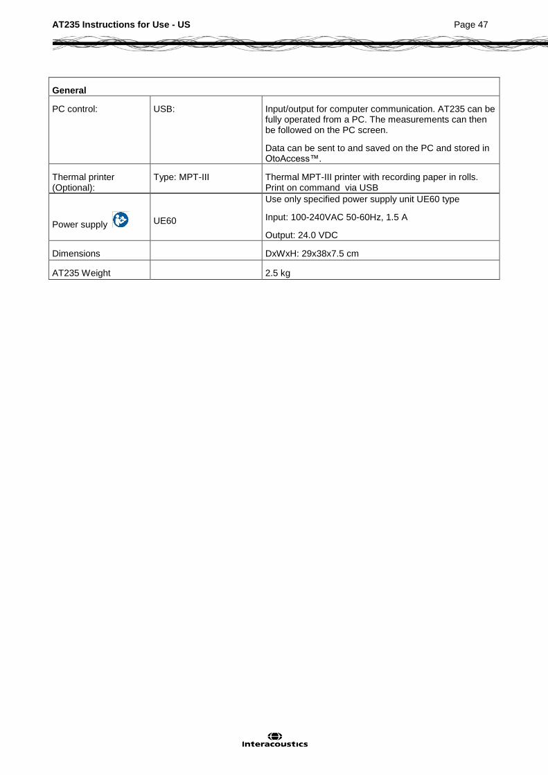
General
PC control: USB: Input/output for computer communication. AT235 can be fully operated from a PC. The measurements can then be followed on the PC screen.
Data can be sent to and saved on the PC and stored in OtoAccess™.
Thermal printer (Optional):
Type: MPT-III Thermal MPT-III printer with recording paper in rolls. Print on command via USB
Power supply UE60
Use only specified power supply unit UE60 type
Input: 100-240VAC 50-60Hz, 1.5 A
Output: 24.0 VDC
Dimensions DxWxH: 29x38x7.5 cm
AT235 Weight 2.5 kg

AT235 Instructions for Use - US Page 48
Table 1: Frequencies and Intensity Ranges
AT235 Maximums IMP
TDH39 CIR33 EARtone 3A / IP30 IPSI
DD45
Center Reading Reading Reading Reading Reading
Freq. Tone NB Tone NB Tone NB Tone NB Tone NB
[Hz] [dB HL] [dB HL] [dB HL] [dB HL] [dB HL] [dB HL] [dB HL] [dB HL] [dB HL] [dB HL]
125 80 65 90 70 85 85 70 60 75 60
250 100 85 100 85 105 100 85 75 100 85
500 115 100 110 100 110 105 100 85 115 100
750 120 105 110 105 120 110 100 85 120 105
1000 120 105 115 105 120 110 105 90 120 105
1500 120 105 115 105 120 110 110 90 120 105
2000 120 105 115 105 120 110 105 90 115 105
3000 120 105 115 105 120 110 95 90 120 105
4000 120 105 110 100 120 105 100 85 115 105
6000 120 100 95 95 105 100 85 80 110 90
8000 105 95 75 80 90 85 80 75 105 95
10000
WB - 115 - 115 - 115 - 95 - 120
LP - 120 - 115 - 120 - 100 - 120
HP - 115 - 115 - 120 - 95 - 120

AT235 Instructions for Use - US Page 49
Specification of input/output connections
Inputs Connector type Electrical properties
Patient response Jack6.3mm Handheld switch:
Pin 1: GND
Pin 2: Signal
when activated
Outputs:
Phones, Left
Phones, Right
Jack, 6.3mm
Jack 6.3mm
Voltage:
Min. load impedance: Pin 1: CH1 GND Pin 2: CH1 OUT
Pin 1: CH1 GND Pin 2: CH1 OUT
Up to 3V rms. by 10 Ohm load
8Ohm Pin 2:
Up to 3V rms. by 10Ohm load
8Ohm Pin 2:
Phones, Contralateral
Jack 6.3mm Voltage:
Min. load impedance:
Pin 1: CH1 GND
Pin 2: CH1 OUT
Up to 3V rms. by 10Ohm load
8
Probe system 15-pin D-sub highdensity with air connection
Data I/O:
USB USB type”B” USB port for communication

AT235 Instructions for Use - US Page 50
Calibration Properties
Calibrated Transducers: Contralateral Earphone: Telephonics TDH39/DD45 with a static force of 4.5N 0.5N and/or EARtone 3A/IP30 and/or CIR33 insert phone
Probe system: Ipsilateral Earphone: is integrated in the probe system
Probe frequency transmitter and receiver and pressure transducer is integrated in the probe system
Accuracy: General Generally the instrument is made and calibrated to be within and better than the tolerances required in the specified standards:
Reflex Frequencies: 1%
Contralateral Reflex and Audiometer Tone Levels:
3 dB for 250 to 4000Hz and 5 dB for 6000 to 8000Hz
Ipsilateral Reflex Tone Levels:
5 dB for 500 to 2000Hz and +5/-10 dB for 3000 to 4000Hz
Pressure measurement :
Compliance measurement:
5% or 10 daPa, whichever is greater
5% or 0.1 ml, whichever is greater
Stimulus Presentation Control:
Reflexes: ON-OFF ratio = ≥ 70 dB
Rise time = 20 ms
Fall time = 20 ms
A weighted SPL in Off = 31 dB
Impedance Calibration Properties
Probe tone Frequencies: 226 Hz 1%, 678 Hz 1%, 800 Hz 1%, 1000 Hz 1%
Level: 85 dB SPL 1.5 dB measured in an IEC 60318-5
acoustic coupler. The level is constant for all volumes in the measurement range.
Distortion: Max 1% THD
Compliance Range: 0.1 to 8.0 ml
Temperature dependence: -
Pressure dependence: -0.00020 ml/daPa
Reflex sensitivity:
Reflex artifact level:
0.001 ml is the lowest detectable volume change
≥95 dB SPL (measured in the 711 coupler, 0.2 ml, 0.5 ml, 2.0 ml & 5.0 ml hardwalled cavities).
Temporal reflex characteristics:
Initial latency = 35 ms (5 ms)
Rise time = 42 ms (5 ms)
Terminal latency = 23 ms (5 ms)
Fall time = 44 ms (5 ms)
AT235 Instructions for Use - US Page 51
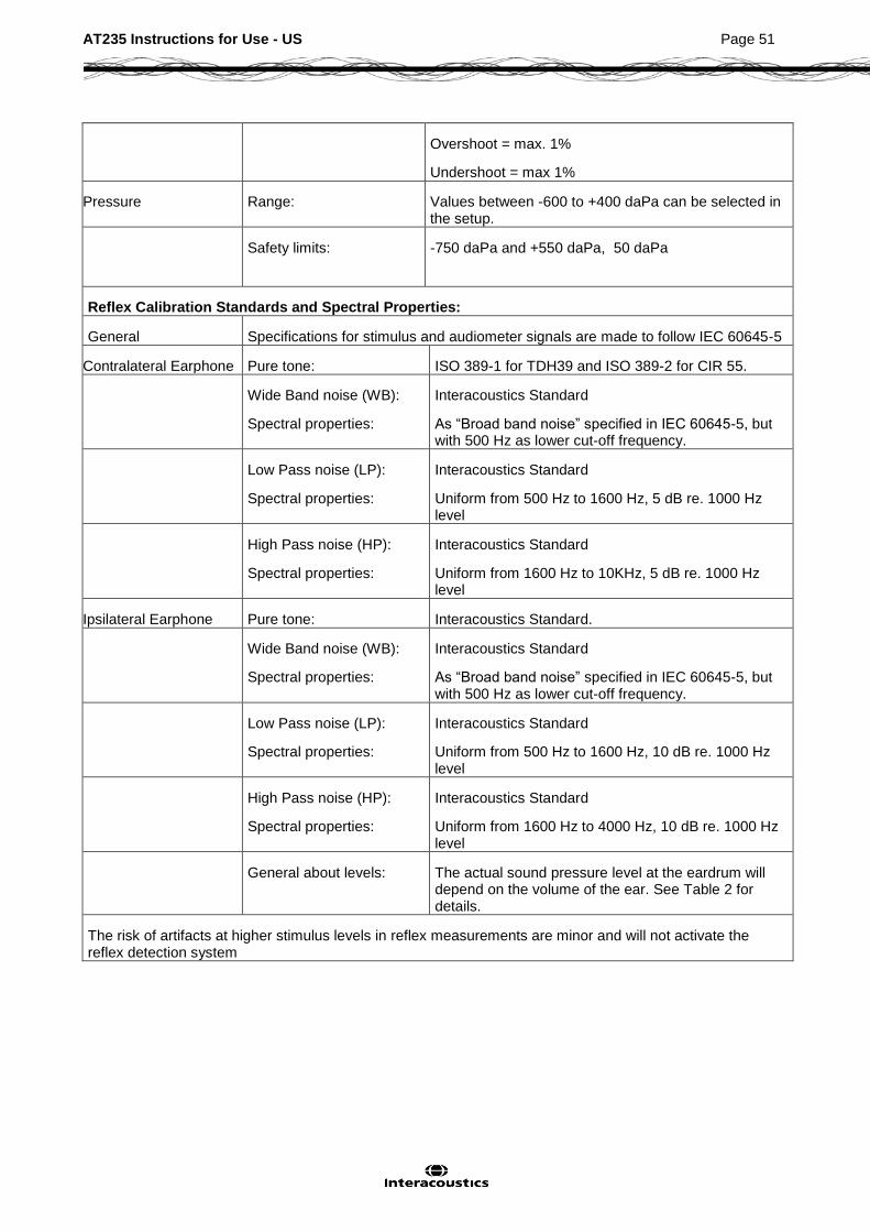
Overshoot = max. 1%
Undershoot = max 1%
Pressure Range: Values between -600 to +400 daPa can be selected in the setup.
Safety limits: -750 daPa and +550 daPa, 50 daPa
Reflex Calibration Standards and Spectral Properties:
General Specifications for stimulus and audiometer signals are made to follow IEC 60645-5
Contralateral Earphone Pure tone: ISO 389-1 for TDH39 and ISO 389-2 for CIR 55.
Wide Band noise (WB):
Spectral properties:
Interacoustics Standard
As “Broad band noise” specified in IEC 60645-5, but with 500 Hz as lower cut-off frequency.
Low Pass noise (LP):
Spectral properties:
Interacoustics Standard
Uniform from 500 Hz to 1600 Hz, 5 dB re. 1000 Hz level
High Pass noise (HP):
Spectral properties:
Interacoustics Standard
Uniform from 1600 Hz to 10KHz, 5 dB re. 1000 Hz level
Ipsilateral Earphone Pure tone: Interacoustics Standard.
Wide Band noise (WB):
Spectral properties:
Interacoustics Standard
As “Broad band noise” specified in IEC 60645-5, but with 500 Hz as lower cut-off frequency.
Low Pass noise (LP):
Spectral properties:
Interacoustics Standard
Uniform from 500 Hz to 1600 Hz, 10 dB re. 1000 Hz level
High Pass noise (HP):
Spectral properties:
Interacoustics Standard
Uniform from 1600 Hz to 4000 Hz, 10 dB re. 1000 Hz level
General about levels: The actual sound pressure level at the eardrum will depend on the volume of the ear. See Table 2 for details.
The risk of artifacts at higher stimulus levels in reflex measurements are minor and will not activate the reflex detection system

AT235 Instructions for Use - US Page 52
Table 3: Reference Values for Stimulus Calibration
Freq. Reference Equivalent Threshold Sound Level
(RETSPL)
[dB re. 20 µPa]
Variation of Ipsi stimulus levels for different volumes of the ear canal
Relative to the calibration performed on an IEC 126 coupler
[dB]
Sound attenuation values for TDH39/DD45 earphones using MX41/AR or PN51 cushion
[dB]
ISO
389
-1
(Int
erac
oust
ics
Sta
ndar
d)
ISO
389
-2
(Int
erac
oust
ics
Sta
ndar
d)
ISO
382
-2
(Int
erac
oust
ics
Sta
ndar
d)
Inte
raco
ustic
s S
tand
ard
Inte
raco
ustic
s S
tand
ard
ISO
389
-4
(IS
O 8
798)
0.5 ml
1 ml
[Hz] TDH39 EARtone 3A / IP30
CIR55 DD45 Probe NB Stimulus Correction Values
RE
TS
PL
125 45 26 26 47.5 41 4 3
250 25.5 14 14 27 24.5 4 5
500 11.5 5.5 5.5 13 9.5 4 9.7 5.3 7
1000 7 0 0 6 6.5 6 9.7 5.3 15
1500 6.5 2 2 8 5 6 21 (1600 Hz)
2000 9 3 3 8 12 6 11.7 3.9 26
3000 10 3.5 3.5 8 11 6 -0.8 -0.5 31 (3150 Hz)
4000 9.5 5.5 5.5 9 3.5 5 -1.6 -0.8 32
6000 15.5 2 2 20.5 3 5 26 (6300 Hz)
8000 13 0 0 12 -5 5 24
WB -8 -5 -5 -8 -5 7.5 3.2
LP -6 -7 -7 -6 -7 8.0 3.6
HP -10 -8 -8 -10 -8 3.9 1.4
*All figures in bold are Interacoustics Standard values.

AT235 Instructions for Use - US Page 53
Coupler Types used for Calibration
IMP:
TDH39 and DD45 is calibrated using a 6cc acoustic coupler made in accordance to IEC 60318-3, Ipsilateral earphone and probe tone are calibrated using a 2cc acoustic coupler made in accordance to IEC 60318-5.
General Information about Specifications
Interacoustics continuously strives to improve its products and their performance. Therefore the specifications can be subject to change without notice.
The performance and specifications of the instrument can only be guaranteed if it is subject to technical maintenance at least once per year. This should be carried out by a workshop authorized by Interacoustics.
Interacoustics puts diagrams and service manuals at the disposal of authorized service companies.
Enquiries about representatives and products may be sent to: Interacoustics A/S Phone: +45 63713555 Drejervaenget 8 Fax: +45 63713522 DK 5610 Assens E-mail: [email protected] Denmark http: www.interacoustics.com

AT235 Instructions for Use - US Page 54
5.2 Electromagnetic Compatibility (EMC) Portable and mobile RF communications equipment can affect the AT235 . Install and operate the AT235 according to the EMC information presented in this chapter. The AT235 has been tested for EMC emissions and immunity as a standalone AT235 . Do not use the AT235 adjacent to or stacked with other electronic equipment. If adjacent or stacked use is necessary, the user should verify normal operation in the configuration. The use of accessories, transducers and cables other than those specified, with the exception of servicing parts sold by Interacoustics as replacement parts for internal components, may result in increased EMISSIONS or decreased IMMUNITY of the device. Anyone connecting additional equipment is responsible for making sure the system complies with the IEC 60601-1-2 standard.
Guidance and manufacturer’s declaration - electromagnetic emissions
The AT235 is intended for use in the electromagnetic environment specified below. The customer or the user of the AT235 should ensure that it is used in such an environment.
Emissions Test Compliance Electromagnetic environment - guidance
RF emissions
CISPR 11
Group 1 The AT235 uses RF energy only for its internal function.
Therefore, its RF emissions are very low and are not likely to cause any interference in nearby electronic equipment.
RF emissions
CISPR 11
Class B The AT235 is suitable for use in all commercial, industrial, business, and residential environments.
Harmonic emissions
IEC 61000-3-2
Complies
Class A Category
Voltage fluctuations /
flicker emissions
IEC 61000-3-3
Complies
Recommended separation distances between portable and mobile RF communications equipment and the AT235 .
The AT235 is intended for use in an electromagnetic environment in which radiated RF disturbances are controlled. The customer or the user of the AT235 can help prevent electromagnetic interferences by maintaining a minimum distance between portable and mobile RF communications equipment (transmitters) and the AT235 as recommended below, according to the maximum output power of the communications equipment.
Rated Maximum output power of transmitter
[W]
Separation distance according to frequency of transmitter
[m]
150 kHz to 80 MHz
d = 1.17
80 MHz to 800 MHz
d = 1.17
800 MHz to 2.5 GHz
d = 2.23
0.01 0.12 0.12 0.23
0.1 0.37 0.37 0.74
1 1.17 1.17 2.33
10 3.70 3.70 7.37
100 11.70 11.70 23.30
For transmitters rated at a maximum output power not listed above, the recommended separation distance d in meters (m) can be estimated using the equation applicable to the frequency of the transmitter, where P is the maximum output power rating of the transmitter in watts (W) according to the transmitter manufacturer.
Note 1 At 80 MHz and 800 MHZ, the higher frequency range applies.
Note 2 These guidelines may not apply to all situations. Electromagnetic propagation is affected by absorption and reflection from structures, objects and people.

AT235 Instructions for Use - US Page 55
Guidance and Manufacturer’s Declaration - Electromagnetic Immunity
The AT235 is intended for use in the electromagnetic environment specified below. The customer or the user of the AT235 should assure that it is used in such an environment.
Immunity Test IEC 60601 Test
Level
Compliance Electromagnetic
Environment-Guidance
Electrostatic Discharge (ESD)
IEC 61000-4-2
+6 kV contact
+8 kV air
+6 kV contact
+8 kV air
Floors should be wood, concrete or ceramic tile. If floors are covered with synthetic material, the relative humidity should be greater than 30%.
Electrical fast transient/burst
IEC61000-4-4
+2 kV for power supply lines
+1 kV for input/output lines
+2 kV for power supply lines
+1 kV for input/output lines
Mains power quality should be that of a typical commercial or residential environment.
Surge
IEC 61000-4-5
+1 kV differential mode
+2 kV common mode
+1 kV differential mode
+2 kV common mode
Mains power quality should be that of a typical commercial or residential environment.
Voltage dips, short interruptions and voltage variations on power supply lines
IEC 61000-4-11
< 5% UT
(>95% dip in UT) for 0.5 cycle
40% UT
(60% dip in UT) for 5 cycles
70% UT
(30% dip in UT) for 25 cycles
<5% UT
(>95% dip in UT) for 5 sec
< 5% UT (>95% dip in UT)
for 0.5 cycle
40% UT (60% dip in UT) for
5 cycles
70% UT (30% dip in UT) for
25 cycles
<5% UT
Mains power quality should be that of a typical commercial or residential environment. If the user of the AT235 requires continued operation during power mains interruptions, it is recommended that the AT235 be powered from an uninterruptable power supply or its battery.
Power frequency (50/60 Hz)
IEC 61000-4-8
3 A/m 3 A/m Power frequency magnetic fields should be at levels characteristic of a typical location in a typical commercial or residential environment.
Note: UT is the A.C. mains voltage prior to application of the test level.
Guidance and manufacturer’s declaration — electromagnetic immunity
The AT235 is intended for use in the electromagnetic environment specified below. The customer or the user of the AT235 should ensure that it is used in such an environment,
Immunity test IEC / EN 60601
test level
Compliance level Electromagnetic environment – guidance
Portable and mobile RF

AT235 Instructions for Use - US Page 56
Conducted RF
IEC / EN 61000-4-6
Radiated RF
IEC / EN 61000-4-3
3 Vrms
150kHz to 80 MHz
3 V/m
80 MHz to 2,5 GHz
3 Vrms
3 V/m
communications equipment should be used no closer to any parts of the AT235 , including cables, than the recommended separation distance calculated from the equation applicable to the frequency of the transmitter.
Recommended separation distance
Pd 2,1
Pd 2,1 80 MHz to 800 MHz
Pd 3,2 800 MHz to 2,5 GHz
Where P is the maximum output power rating of the transmitter in watts (W) according to the transmitter manufacturer and d is the recommended separation distance in meters (m).
Field strengths from fixed RF transmitters, as determined by an electromagnetic site survey, (a) should be less than the compliance level in each frequency range (b)
Interference may occur in the vicinity of equipment marked with the following symbol:
NOTE1 At 80 MHz and 800 MHz, the higher frequency range applies
NOTE 2 These guidelines may not apply in all situations. Electromagnetic propagation is affected by absorption and reflection from structures, objects and people.
(a) Field strengths from fixed transmitters, such as base stations for radio (cellular/cordless) telephones and land mobile radios, amateur radio, AM and FM radio broadcast and TV broadcast cannot be predicted theoretically with accuracy. To assess the electromagnetic environment due to fixed RF transmitters, an electromagnetic site survey should be considered. If the measured field strength in the location in which the AT235 is used exceeds the applicable RF compliance level above, the AT235 should be observed to verify normal operation, If abnormal performance is observed, additional measures may be necessary, such as reorienting or relocating the AT235 .
(b) Over the frequency range 150 kHz to 80 MHz, field strengths should be less than 3 V/m.

AT235 Instructions for Use - US Page 57
To ensure compliance with the EMC requirements as specified in IEC 60601-1-2, it is essential to use only the following accessories:
ITEM MANUFACTURER MODEL
Power supply unit UE60 Interacoustics UE60-240250SPAx
Clinical Probe Interacoustics Clinical probe system 1077
Diagnostic prob Interacoustics Diagnostic probe system 1077
DD45C Contra Headset DD45C contra headset P3045
Interacoustics DD45C
IP30 Insert Phone 10ohm single contraEARTone 3A with Minijack
Interacoustics Ear3AIP30C
DD45 Audiometric Headset P3045 Interacoustics DD45
IP30 Insert Phone 10ohm set Interacoustics IP30
Conformance to the EMC requirements as specified in IEC 60601-1-2 is ensured if the cable types and cable lengths are as specified below:
Description Length Screened?
Mains Cable 2.0m Unscreened
USB Cable 2.0m Screened
Clinical Probe 2.0m Unscreened
Diagnostic prob 2.0m Unscreened
DD45C contra headset P3045 0.4m Screened
IP30 Insert Phone 10ohm single contra
0.5m Screened
DD45 Audiometric Headset P3045 0.5m Screened
IP30 Insert Phone 10ohm set 0.5m Screened


Return Report – Form 001
Opr. dato: 2014-03-07
af: EC
Rev. dato:
af: MSt
Rev. nr.: 4
Page 1 of 1
Company:
Address:
Phone:
Fax or e-mail:
Contact person:
Date :
Following item is reported to be:
returned to INTERACOUSTICS for: repair, exchange, other:
defective as described below with request of assistance
repaired locally as described below
showing general problems as described below
Item: Type: Quantity:
Serial No.: Supplied by:
Included parts:
Important! - Accessories used together with the item must be included if returned (e.g. external power supply, headsets, transducers and couplers).
Description of problem or the performed local repair:
Returned according to agreement with: Interacoustics, Other :
Date : Person :
Please provide e-mail address or fax No. to whom Interacoustics may confirm reception of the returned goods:
The above mentioned item is reported to be dangerous to patient or user 1
In order to ensure instant and effective treatment of returned goods, it is important that this form is filled in and placed together with the item. Please note that the goods must be carefully packed, preferably in original packing, in order to avoid damage during transport. (Packing material may be ordered from Interacoustics)
1 EC Medical Device Directive rules require immediate report to be sent, if the device by malfunction deterioration of performance or characteristics and/or by inadequacy in labelling or instructions for use, has caused or could have caused death or serious deterioration of health to patient or user.
Address
7625 Golden Triangle Drive Eden Prairie MN 55344 USA Phone (+1) 800 947 6334 Fax (+1) 952 903 4200 E-mail [email protected]