instructions for use multimat easy
TRANSCRIPT

Instructions for Use
Multimat®Easy
GB


Page 1
The text and illustrations of these Instructions for Use have been compiled with the utmost diligence. Nevertheless, the presence of typographic errors or incorrect data cannot be excluded. Please note that DeguDent GmbH will not be responsible for such errors.

Page 2
Content 1 General ....................................................................................................................................................... 4
1.1 About these Instructions for Use .......................................................................................................... 4
1.2 Layout elements used in these Instructions for Use ............................................................................ 4
1.3 Device type and year of manufacture .................................................................................................. 5
1.4 Manufacturer and service addresses ................................................................................................... 5
1.5 Intellectually property rights.................................................................................................................. 5
1.6 Proper use ............................................................................................................................................ 5
2 Safety notes ............................................................................................................................................... 6
2.1 Safe transport ....................................................................................................................................... 6
2.2 Safe operation ...................................................................................................................................... 7
2.3 Safe maintenance and troubleshooting ................................................................................................ 7
2.4 Safe handling of ceramic fibres ............................................................................................................ 7
2.5 Warning decals on the unit ................................................................................................................... 8
3 Technical description ................................................................................................................................ 8
3.1 Base unit............................................................................................................................................... 8
3.2 Connectors ........................................................................................................................................... 9
3.3 Scope of delivery .................................................................................................................................. 9
3.4 Optional accessories ..........................................................................................................................10
3.5 Technical specifications and operating environment .........................................................................10
3.6 Features .............................................................................................................................................11
4 Commissioning ........................................................................................................................................12
4.1 Unpacking and checking accessories ................................................................................................12
4.2 Setting up and connecting ..................................................................................................................12
4.3 Dehydration ........................................................................................................................................12
5 Operation ..................................................................................................................................................13
5.1 Control panel ......................................................................................................................................13
5.2 Display ................................................................................................................................................14
5.3 Firing parameters ...............................................................................................................................15
5.4 Moving through the menus/Menu overview .......................................................................................17
5.5 Menu explanations .............................................................................................................................18
6 Operation ..................................................................................................................................................19
6.1 Turning on the unit/Starting a firing program......................................................................................19
6.2 Designing and starting your own firing program ................................................................................20
6.3 View function (soldering) ....................................................................................................................22
6.4 Entering standby mode ......................................................................................................................22
6.5 Fast cooling or manual fast cooling ....................................................................................................22
7 Maintenance and cleaning ......................................................................................................................23
7.1 Firing support maintenance ................................................................................................................23
7.2 Replacing the firing muffle ..................................................................................................................23
7.3 Vacuum pump maintenance...............................................................................................................23
8 Calibration using a silver wire test ........................................................................................................24
8.1 Silver wire calibration program ...........................................................................................................25

Page 3
8.2 Entering the calibration offset ............................................................................................................. 25
9 Error messages and troubleshooting ................................................................................................... 26
9.1 Power failure ...................................................................................................................................... 27
10 Pre-defined programs ......................................................................................................................... 28
11 Disposal ................................................................................................................................................ 30
12 EC Declaration of Conformity ............................................................................................................. 31

Page 4
Dear customer, Thank you for your confidence in Multimat
® Easy. This furnace for firing and pressing dental ceramics is a safe
high-quality device featuring numerous automated functions. It is characterized by ease of handling and minimal training requirements.
The device is almost maintenance-free and suitable for continuous operation.
We hope you will appreciate your results with the Multimat® Easy.
1 General
1.1 About these Instructions for Use
Compliance with these Instructions for Use is a prerequisite for the successful and safe operation of the Multimat
® Easy. These Instructions for Use contain important information for operating this device in a safe,
appropriate and economic manner. Compliance with these Instructions for Use also helps avoid hazards, limits repair costs and downtime and increases the reliability and prolongs the life of the Multimat
® Easy.
These Instructions for Use must be continuously present near the unit and must be read by all persons working with the Multimat
® Easy.
DeguDent GmbH will not be responsible for any damage caused by improper use or operation of the Multimat
®
Easy and/or non-compliance with these Instructions for Use.
1.2 Layout elements used in these Instructions for Use
Safety notes related to personal injury, accidents or property damage:
The unit must be opened only by authorized DeguDent GmbH authorized personnel!
Step-by-step instructions
1. Remove ...
2. Locate ...
Designations for user interface elements:
Menu key
Emphasis:
The front of the unit includes display (1) with its ...
Additional notes and hints:
Note: You may also use existing programs to …
Page 5
1.3 Device type and year of manufacture
Multimat® Easy
Year of manufacture: from 2008
1.4 Manufacturer and service addresses
DeguDent GmbH
Rodenbacher Chaussee 4
63457 Hanau
Germany
Tel.: +49 180 23 24 555
Fax: +49 180 23 24 556
1.5 Intellectually property rights
© 2011, DeguDent GmbH
All rights pertaining to these Instructions for Use, including but not limited to photocopying and dissemination as well as translation, are reserved for DeguDent GmbH. Specifically, these Instructions for Use must not, whether in whole or in part, be reproduced in any form (print, photocopy, microfilm or other technologies) and/or stored, processed, copied or disseminated using electronic data storage and retrieval systems without prior written approval by DeguDent GmbH.
Violations of these rights will be prosecuted and will make the guilty party liable for damages. All intellectual property, trademark, service mark and other rights are reserved by DeguDent GmbH.
1.6 Proper use
The Multimat® Easy is a device for firing dental ceramic materials. Observe the alloy and ceramic
manufacturers’ directions and recommendations. Any use outside or beyond these directions or specifications does not constitute proper use. Any damage resulting from such use will be the sole responsibility of the user of the Multimat
® Easy. The same applies for
any unauthorized changes to the unit. Proper use presupposes compliance with all notes on
safety,
operation,
care, maintenance and trouble shooting,
described in these Instructions for Use. The unit is intended solely for dental laboratory use. Any use in other locations or for other purposes requires prior written approval of DeguDent GmbH.
Page 6
2 Safety notes
All DeguDent GmbH devices are designed and produced using state-of-the-art technology and following all recognized safety rules.
Nevertheless, using these devices may result in hazards to operators or third parties or damage to the Multimat
® Easy or other property, e.g. if:
The unit is operated by untrained or not properly instructed personnel
The unit is not employed for its appropriate uses
The unit has not been properly operated or maintained
Use only qualified and trained personal to perform the tasks described in these Instructions for Use. Observe any applicable legal age restrictions! Personnel to be trained or guided, including vocational trainees, must work with the Multimat
® Easy only if
continuously supervised by an experienced operator!
2.1 Safe transport
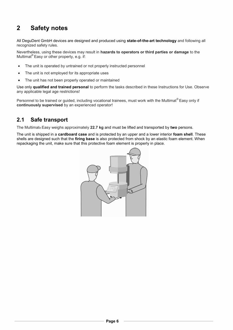
The Multimat® Easy weighs approximately 22.7 kg and must be lifted and transported by two persons.
The unit is shipped in a cardboard case and is protected by an upper and a lower interior foam shell. These shells are designed such that the firing base is also protected from shock by an elastic foam element. When repackaging the unit, make sure that this protective foam element is properly in place.

Page 7
2.2 Safe operation
To ensure safe operation of the unit, read and follow the following instructions:
Do not place the Multimat® Easy press and the vacuum pump (available separately) in the immediate
vicinity of sources of heat to prevent overheating of the unit.
Keep the device clear of the nearest wall or object. The minimum distance is 25 to 30 cm.
Place the unit only on non-flammable surfaces. Keep flammable objects and liquids away from the device.
Position the vacuum pump such that adequate ventilation is assured.
Protect the unit from moisture and steam.
Ensure that the unit and the vacuum pump (available separately) are connected only to the appropriate mains voltage (see 3.5 Technical specifications and operating environment, page 10)
Never open the unit under any circumstances. Electric shock hazard!
Do not operate the unit unless it is firmly placed on the firing base to avoid excessive wear and tear on the seals of the firing platform, which might even result in deformation of the carrier plate.
Use only your fingers or a stylus to operate the touch screen. Do not touch the screen with pointed or hot objects.
The firing platform moving upward presents a crushing hazard for hands and fingers!
If the Multimat® Easy is not to be used for an extended period, disconnect the unit from mains.
Make sure the mains plug of the power cord is readily accessible so the unit can be disconnected easily and quickly in the event of an emergency.
2.3 Safe maintenance and troubleshooting
Observe the following rules during maintenance, repairs, or troubleshooting tasks:
All repairs must be performed by authorized DeguDent personnel only.
All work on electrical components must be performed by qualified electricians.
Disconnect from mains before opening the unit.
Use only original replacement parts.
Some components of the Multimat® Easy are subject to a certain amount of wear and tear.
It is therefore recommended to subject the unit to technical inspections at yearly intervals.
2.4 Safe handling of ceramic fibres
The heat insulation of the firing chamber and the firing base contain ceramic fibres that have been rated as carcinogenic. Measurements performed on a ceramic furnace while in use have shown that the actual level of these fibres is significantly lower than the acceptable risk threshold if the furnace is used as per the manufacturer’s instructions.
Any damage to the furnace must be repaired by a recognized expert (e.g. DeguDent’s Technical Service). Visible deposits of fibres are freely accessible parts of the furnace must be removed by approved cleaning methods (e.g. by wiping them off with a moist cloth or by vacuuming using approved filters). Fibres must never be blown away with compressed air nor brushed away with brooms were brushes while still dry. Should you detect unusual quantities of visible fibre deposits on freely accessible parts of the furnace, please contact a recognized expert as mentioned above. Use of defective accessories containing ceramic fibres must be discontinued immediately.
Page 8
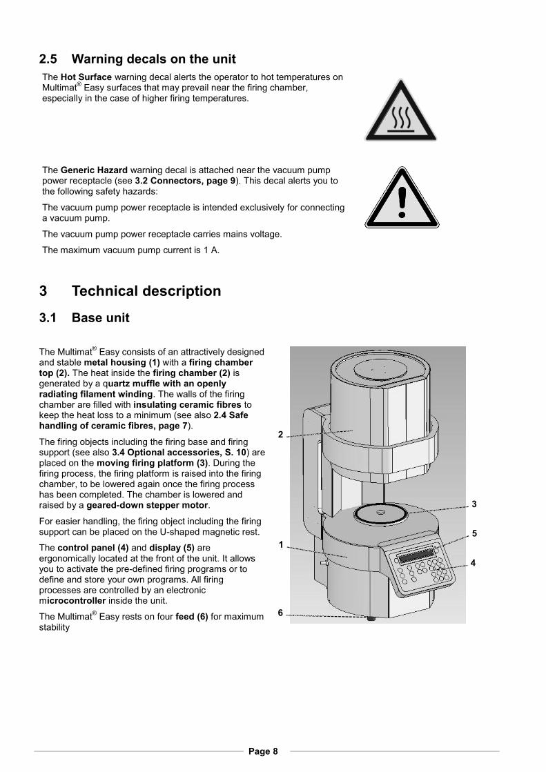
2.5 Warning decals on the unit
The Hot Surface warning decal alerts the operator to hot temperatures on Multimat
® Easy surfaces that may prevail near the firing chamber,
especially in the case of higher firing temperatures.
The Generic Hazard warning decal is attached near the vacuum pump power receptacle (see 3.2 Connectors, page 9). This decal alerts you to the following safety hazards:
The vacuum pump power receptacle is intended exclusively for connecting a vacuum pump.
The vacuum pump power receptacle carries mains voltage.
The maximum vacuum pump current is 1 A.
3 Technical description
3.1 Base unit
The Multimat® Easy consists of an attractively designed
and stable metal housing (1) with a firing chamber top (2). The heat inside the firing chamber (2) is generated by a quartz muffle with an openly radiating filament winding. The walls of the firing chamber are filled with insulating ceramic fibres to keep the heat loss to a minimum (see also 2.4 Safe handling of ceramic fibres, page 7).
The firing objects including the firing base and firing support (see also 3.4 Optional accessories, S. 10) are placed on the moving firing platform (3). During the firing process, the firing platform is raised into the firing chamber, to be lowered again once the firing process has been completed. The chamber is lowered and raised by a geared-down stepper motor.
For easier handling, the firing object including the firing support can be placed on the U-shaped magnetic rest.
The control panel (4) and display (5) are ergonomically located at the front of the unit. It allows you to activate the pre-defined firing programs or to define and store your own programs. All firing processes are controlled by an electronic microcontroller inside the unit.
The Multimat® Easy rests on four feed (6) for maximum
stability
1
2
3
4
5
6

Page 9
3.2 Connectors
The following connectors are available:
Primary power connector (7),
On/off switch with automatic circuit breaker (8),
RJ45 connector (9) (for service purposes only),
2 x USB connectors (10) for service updates via USB,
Vacuum pump air hose connector (11),
Vacuum pump power connector (12) to provide the optional vacuum pump with mains power. The vacuum pump power connector is intended exclusively for connecting a vacuum pump. The vacuum pump power connector carries mains voltage.
The maximum vacuum pump current is 1 A.
3.3 Scope of delivery
The scope of delivery includes:
Multimat® Easy ceramic firing furnace
Mains cable for high-temperature devices
Instructions for Use
One firing base (13)
One firing support (14)
One U-shaped rest, magnetic (15)
One pair of tweezers
Image shows carrier bottom
14
13
15
7 11
12
8
7
11
10
9
12
8
Page 10
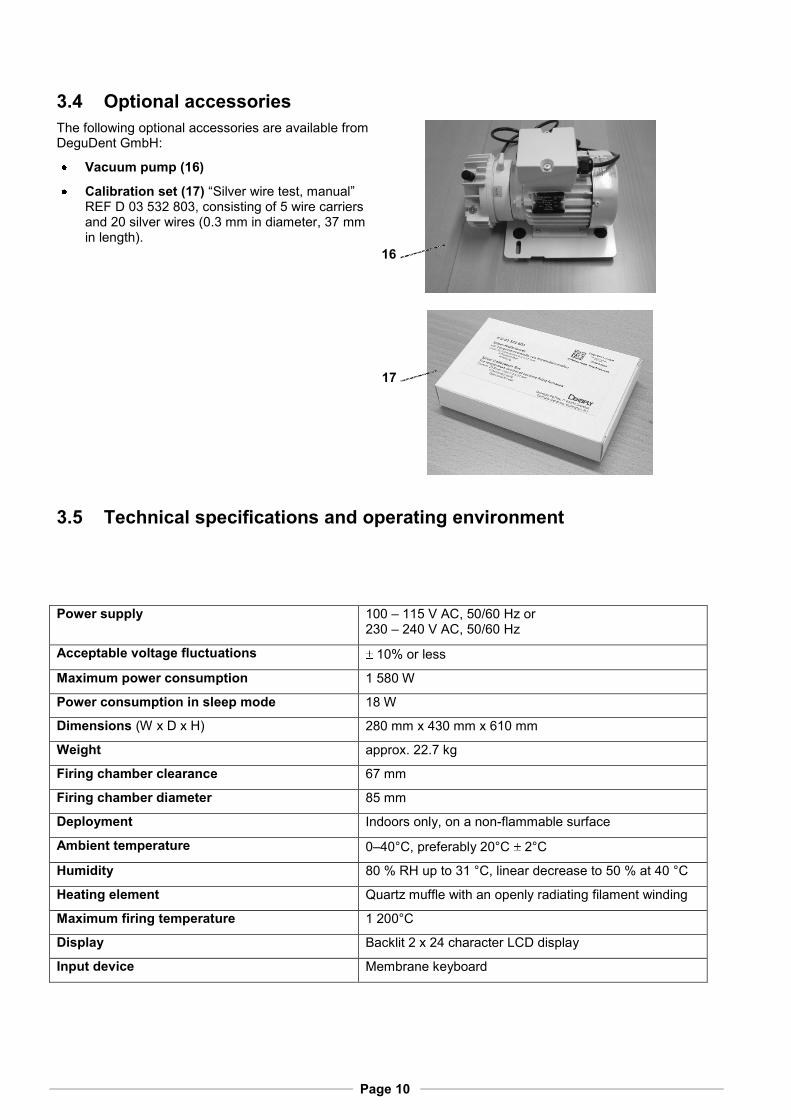
3.4 Optional accessories
The following optional accessories are available from DeguDent GmbH:
Vacuum pump (16)
Calibration set (17) “Silver wire test, manual” REF D 03 532 803, consisting of 5 wire carriers and 20 silver wires (0.3 mm in diameter, 37 mm in length).
3.5 Technical specifications and operating environment
Power supply 100 – 115 V AC, 50/60 Hz or 230 – 240 V AC, 50/60 Hz
Acceptable voltage fluctuations 10% or less
Maximum power consumption 1 580 W
Power consumption in sleep mode 18 W
Dimensions (W x D x H) 280 mm x 430 mm x 610 mm
Weight approx. 22.7 kg
Firing chamber clearance 67 mm
Firing chamber diameter 85 mm
Deployment Indoors only, on a non-flammable surface
Ambient temperature 0–40°C, preferably 20°C 2°C
Humidity 80 % RH up to 31 °C, linear decrease to 50 % at 40 °C
Heating element Quartz muffle with an openly radiating filament winding
Maximum firing temperature 1 200°C
Display Backlit 2 x 24 character LCD display
Input device Membrane keyboard
16
17

Page 11
3.6 Features
Comprehensive firing data display
100 programs freely programmable and storable programs; numerous predefined sample programs available
Programs may be modified during the cycle.
Existing programs can be modified and saved as special programs
Copying an existing program to a different program number
Up to 99 minutes vacuum time
Set vacuum display
Adjustable vacuum
Up to 99 minutes of firing time
Up to 25 minutes of firing and pre-heating time
Heating rates of 1 – 120°C/minute
Cooling available in 3 cooling levels
Manual or programmable fast cooling via vacuum pump
Time-to-completion countdown display
Overheating protection and muffle monitoring
High-precision temperature settings
Standby operation to avoid moisture in the firing chamber
Vacuum program to avoid moisture in the fibre insulation
Global hours-of-operation counter
Vacuum pump hours-of-operation indicator
Language selection
Error message display
Automatic continuation after short-term power-outs
Unlimited data retention after power-outs
Automatic mains frequency detection
Beep signals, can be deactivated
Entering of a calibration offset following calibration with a silver wire

Page 12
4 Commissioning
4.1 Unpacking and checking accessories
1. Check the Shock watch sticker on the cardboard box. If the sticker has turned red, the impact energy during transport was higher than allowed, and your unit could be damaged. Ask the transport agent to confirm the triggering of the Shock watch label in writing.
2. Open the cardboard case and remove the upper foam shell
3. Remove the unit including its accessories. The first person must hold the unit with both hands below the control panel at the front of the unit, while the other person must hold the base of the unit with both hands. Have two persons lift the unit from its packing case, then remove the components and accessories. Always have two persons transport the unit. See illustration on page 6.
4. Check the delivery for completeness (see 3.3 Scope of delivery, page 9) or damage in transit. Notify DeguDent GmbH immediately of any damage.
4.2 Setting up and connecting
1. Place the device on a sturdy, non-flammable surface. The minimum distance from the nearest wall or object is 25 to 30 cm (see also 2.2 Safe operation, page 7).
2. Connect the device end of the mains cable to the unit. Connect the mains plug of the mains cable to a properly installed and protected mains socket (see also 3.5 Technical specifications and operating environment, page 10). The Multimat
® Easy must be the only device on
its circuit. No extension cords may be used.
3. Connect the tubing between the vacuum pump (available separately) and the air inlet that the device (see illustration).
4. Place the firing base on the firing lift; use the magnetic firing platform where appropriate.
4.3 Dehydration
After transport and before operating the Multimat® Easy for the first time or after prolonged periods of non-
use, it is recommended to dehydrate the unit. To do so, choose the special dehydration program from among the pre-defined programs (see 5.5 Menu explanations, page 18), which will perform the dehydrating. For instructions on starting a program, see 6.1 Turning on the unit/Starting a firing program, page 19.

Page 13
5 Operation
5.1 Control panel
All parameters are shown on the display and can be entered or edited here. Parameters are entered exclusively via the keys of the control panel (membrane keyboard). Use the keys of the membrane keyboard to make your entries, which will be reflected in the display (see also 5.2 Display, page 14), or to switch between different menus (see “Moving through the menus/Menu overview”)
(1) Display: Shows all firing parameters (see also 5.2 Display, page. 14).
(2) On/off key: Turns the controller on or off. When turned off, the firing chamber will be closed by the firing platform, and the unit will be in standby mode (vacuum and standby temperature).
(3) keys: Move the firing platform upward/down
(4) Star key: Activate fast cooling using the vacuum pump
(5) Menu key: Calls the configuration menu; from there additional submenus for system configuration can be invoked (see 5.4 Moving through the menus/Menu overview, page 17)
(6) P key: Runs a specific program directly.
(7) S key: Saves the parameters shown on the display.
(8) ◄► keys: For moving within menus (see “Moving through menus/Menu overview”)
(9) –/+ keys: Increases/decreases parameter
values.
(10) ESC key: Returns without applying changes.
(11) ENTER key: Confirms and applies changes.
(12) Numeric keypad: For entering parameter values, digits 0 to 9.
(13) Start/stop key: Starts/Stops the firing program.
(14) Green LED: Lit while firing program is running.
1
2
5
4
3
6 7 8 9 10 11
12
13
14

Page 14
5.2 Display
(1) Program number, max. 99 programs
(2) Fast cooling indicated by
(3) Pre-heating temperature, 100 to 350°C
(4) Heating rate, 1 to 120°C/minute
(5) Pre-set firing temperature, 300 to 1200°C
(6) Actual firing temperature, 0 to 1250°C
(7) Remaining firing time, 00 to 99 min
(8) Pre-set drying time, 0 to 25 min
(9) Pre-set pre-heating time, 0 to 25 min
(10) vacuum on/off, vacuum level, 1 to 99 hPa
(11) vacuum time, 0.0 to 99.9 min
(12) Pre-set firing time, 0.0 to 99.9 min
(13) Cooling stage, 0, 1, 2 or 3
1 2 3 4 5 6
7 8 9 10 11 12 13

Page 15
5.3 Firing parameters
(1) Program number: A maximum of 99 programs can be stored. The current number is shown on the display as a two-digit figure.
(2) Fast cooling indicator: Fast cooling means that the vacuum pump is turned on and will suck in air through the firing chamber until the base temperature is reached. If the fast cooling function is activated, an asterisk is shown. Cooling proceeds until the base temperature is reached (see 6.5 Fast cooling or manual fast cooling, page 22)
(3) Pre-heating temperature: The temperature to be reached prior to firing. Select a value between 100°C and 1200°C.
(4) Heating rate: This is the speed of the temperature increase during the heating face. Select a value between 1°C and 120°C per minute.
(5) Pre-set firing temperature: The temperature to be reached during firing. Select a value between 300 to 1200°C.
(6) Actual firing temperature: The current temperature in the firing chamber. Select a value between 0 to 1250°C.
(7) Remaining firing time: The remaining firing time in minutes as shown.
(8) Pre-set drying time: The chamber is heated in order to reach the pre-heating temperature. During this time, the firing chamber will gradually close. Select a duration between 0 and 25 minutes.
(9) Pre-set pre-heating time: The chamber is heated in order to reach the pre-heating temperature. During this time, the firing chamber will be closed. Select a duration between 0 and 25 minutes in a maximum of two places.
(10) Vacuum on/off, vacuum level: If a vacuum is present, its magnitude is displayed here. The vacuum is displayed as a value between 1 hPa and 99 hPa.
(11) Vacuum time: The time during which the vacuum pump will be running. Select a value between 0.0 and 99.9 minutes.
(12) Pre-set firing time (holding time): The duration of the firing. Select a value between 0.0 and 99.9 minutes.
(13) Cooling stage: Cooling in multiple stages results in a gradual release of tension within the ceramic material. If selected under (2) the progression of cooling stages will begin immediately after firing (12).
Stage 0 – Firing platform immediately moves to is bottom position, no cooling.
Stage 1 – Firing object is lowered by approx. 7 cm
Stage 2 – Firing object is lowered by approx. 5 cm
Stage 3 – Firing object remains in the chamber
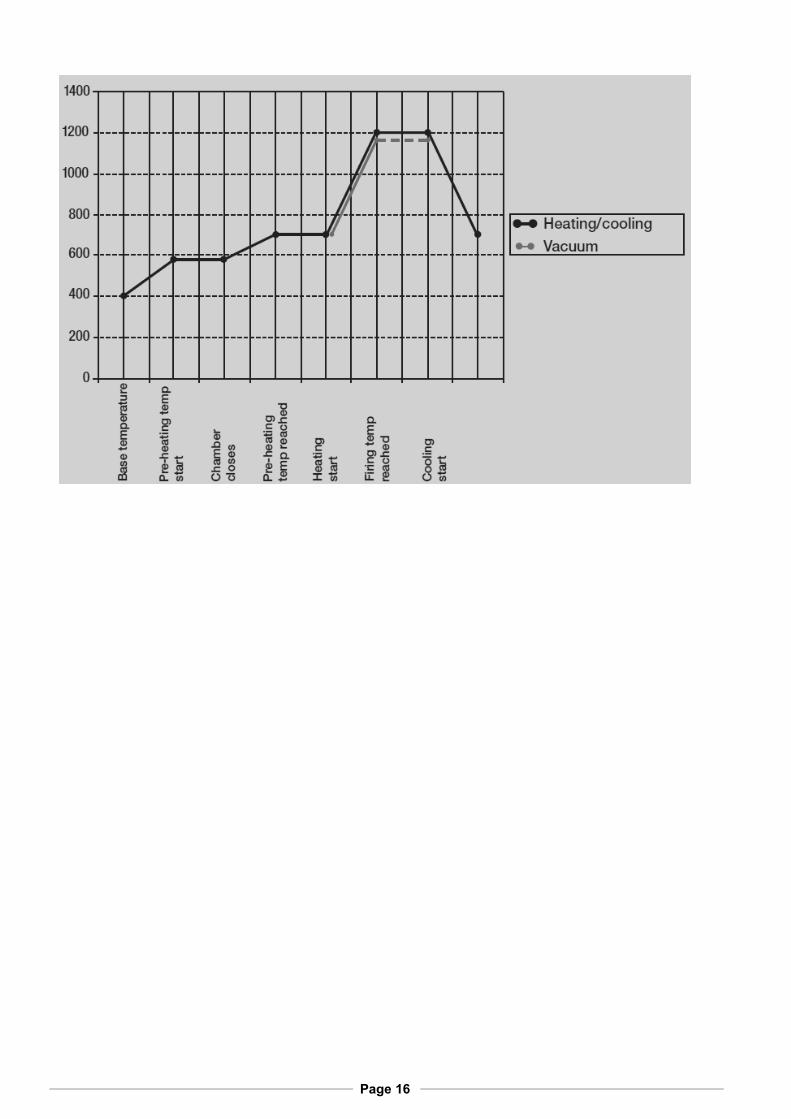
The starting point in each case is the base temperature (pre-set to 400°C). Once the program has been started, the unit pre-heats to the pre-set pre-heating temperature (e.g. 575°C) (see also “Pre-heating temp start”). During the drying phase (8), the firing chamber is gradually closed. Closure will be completed at the end of the drying phase, as the pre-heating temperature reaches its pre-set value. The program then waits out the pre-set pre-heating time (9) and starts the vacuum pump. Once the full vacuum has been attained, this is followed by the heating phase.
Page 16

Page 17
5.4 Moving through the menus/Menu overview
The values discusses in 5.3 Firing parameters, page 15 are shown in the main menu, which is displayed when the unit is operating or when new programs are being programmed. On power-up, additional menus may appear before the main menu. From the main menu, use the Menu key to invoke numerous submenus where additional parameters can be configured. To return to the previous menu, press the ESC key. The following menu overview explains what keys can be used in their respective menus:

Page 18
5.5 Menu explanations
The first message of the start-up sequence after the unit is turned on.
After turning on, the unit performs a self-test to check all systems and input/output connectors.
The values discussed in 5.3, Firing parameters, page 15 are shown in the main menu, which is always displayed when the unit is operating.
Here you can invoke additional submenus for system configuration (see also 5.4, Moving through the menus/Menu overview, page 17)
Here you can enter a calibration offset determined by a calibration using a silver wire test (see 8.2 Entering the calibration offset, page 25).
Here you can examine the running times of the muffle, the vacuum pump and the furnace.
Here you can delete programs you have saved.
Here you can load programs from internal memory.
Here you can start a software update, provided a USB memory stick with the new software version has been inserted.
The program is used for dehydrating the insulation layer after prolonged periods of non-use or before operating the unit for the first time. During dehydration, the temperature is set to 1,000°C, the firing chamber is opened 10 mm and the vacuum pump sucks in air through the open firing chamber. The vacuum level, temperature and time will be displayed The program displays elapsed time in seconds. The total program execution time is 1800 seconds = 30 minutes.
During vacuum testing, a vacuum of down below 50 hPa is created. The valve is closed, and the pump is turned off. Subsequently, the program will be continuously executed until testing is cancelled by pressing a key. During testing, the current vacuum level is displayed. After 10 minutes, this value should not have increased by more than 30 hPa (or in other words, it should remain at or below 80 hPa).
Here you can start a data backup.
In the Configuration menu you can change the language in which the menus are displayed.
Language
[German, English]
Data backup
Vacuum test
Dehydration
Update
Replace program
No. 91-99?
Delete program
No. 91-99
Running times
Calibration
Configuration
Main menu
(last program)
Selftest
Multimat Easy
V1.00 …booting…

Page 19
Here you can pre-set the base temperature (default: 400 °C); see the diagram in 5.3 Firing parameters, page 15.
Here you can determine whether the muffle will heat in standby mode (see 6.4 Entering standby mode, page 22).
Here you can determine whether the vacuum pump will run in standby mode (see 6.4 Entering standby mode, page 22) and what vacuum level (in hPa) is set.
The vacuum pump will suck in air through the open firing chamber until the base temperature is reached.
Here you can switch between °C and °F as a temperature unit.
Her you can turn the beep signals on or off. If the beep signal is turned on you get: A long tone for each invalid entry – three tones at the end of a program. The volume of the acoustic signal can be set to one of five different levels – or the signal can be turned off completely – by using the + and – keys. Press the Return key to accept the new setting.
Indicates the operating hours for the muffle.
Indicates the operating hours for the vacuum pump.
Indicates the total operating hours for the Multimat® Easy.
6 Operation
6.1 Turning on the unit/Starting a firing program
1. Turn on the unit with the on/off key. The controller will be started and performance self-test.
2. The main menu will be shown, indicating the program last run.
3. Move the firing platform down using the key.
Place the firing object with firing base and firing support on the firing platform.
4. If you wish to start the program currently shown, press the start/stop key. The green LED will be lit.
Selftest
Multimat Easy
V1.00 …booting…
Hours furnace:XX:YY
Hours pump:XX:YY
Hours muffle:XX:YY
Acoustic signal
[On-volume]
°C / °Fahrenheit
[°C/°F]
Fast cooling
[On/Off]
Standby vacuum
[000 hPa]
Standby temperature
[000 °C]
Basic temperature
[°C/°F]
Page 20
6.2 Designing and starting your own firing program
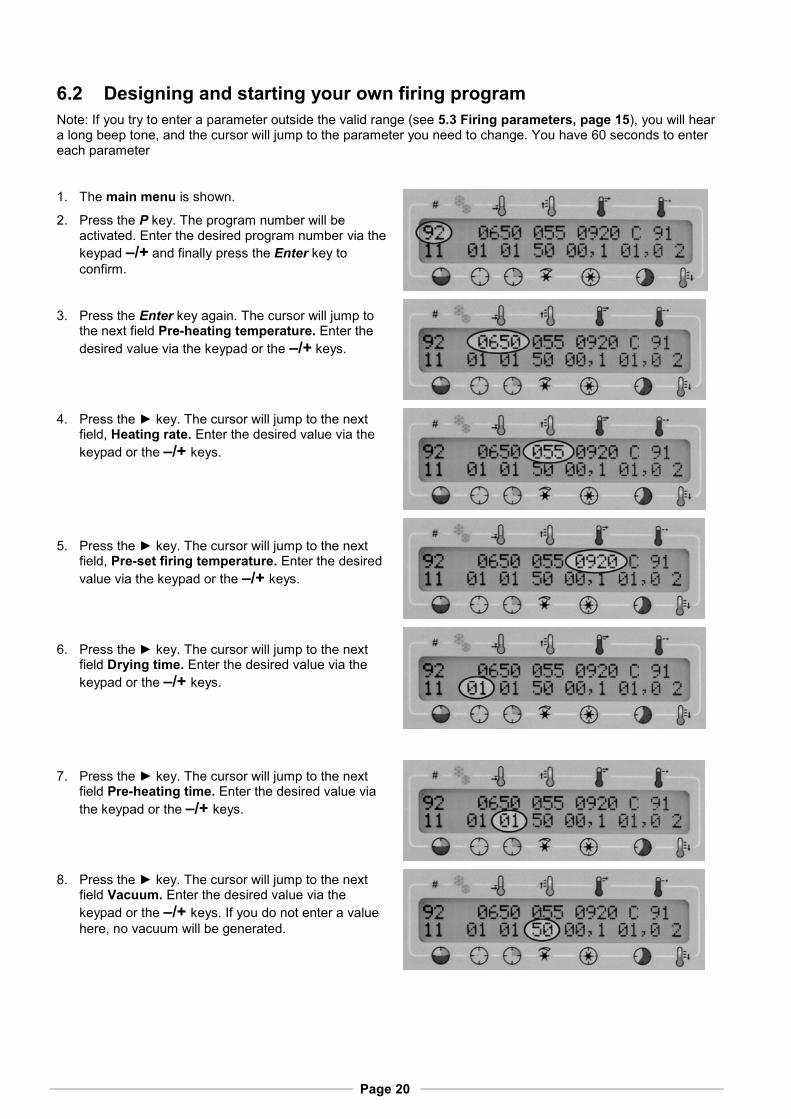
Note: If you try to enter a parameter outside the valid range (see 5.3 Firing parameters, page 15), you will hear a long beep tone, and the cursor will jump to the parameter you need to change. You have 60 seconds to enter each parameter
1. The main menu is shown.
2. Press the P key. The program number will be activated. Enter the desired program number via the
keypad –/+ and finally press the Enter key to
confirm.
3. Press the Enter key again. The cursor will jump to the next field Pre-heating temperature. Enter the
desired value via the keypad or the –/+ keys.
4. Press the ► key. The cursor will jump to the next field, Heating rate. Enter the desired value via the
keypad or the –/+ keys.
5. Press the ► key. The cursor will jump to the next field, Pre-set firing temperature. Enter the desired
value via the keypad or the –/+ keys.
6. Press the ► key. The cursor will jump to the next field Drying time. Enter the desired value via the
keypad or the –/+ keys.
7. Press the ► key. The cursor will jump to the next field Pre-heating time. Enter the desired value via
the keypad or the –/+ keys.
8. Press the ► key. The cursor will jump to the next field Vacuum. Enter the desired value via the
keypad or the –/+ keys. If you do not enter a value
here, no vacuum will be generated.

Page 21
9. Press the ► key. The cursor will jump to the next field Vacuum time. Enter the desired value via the
keypad or the –/+ keys.
10. Press the ► key. The cursor will jump to the next field Firing time. Enter the desired value via the
keypad or the –/+ keys.
11. Save your newly defined program by pressing the S and Enter keys to store the program under the selected program number. If you wish to store the newly defined program under a different program number, press the S key and then select a new
number using the keypad or the –/+ keys. Confirm
your entry by pressing the Enter key.
12. To copy a program, press the S key and then select the number of the program to be copied by using the
keypad or the –/+ keys. Confirm your entry by
pressing the Enter key. Now press the S key and then select a new number using the keypad or the
–/+ keys. Confirm your entry by pressing the Enter
key.
To start the program, press the start stop key. The green LED will be lit (see 6.1 Turning on the unit/Starting a firing program, page 19). The remaining firing time field indicates how long the program still has to run.
Note: The following keys can be used while a program is running:
(3) keys: Lift, (13) start stop keys: stops the running firing program.

Page 22
6.3 View function (soldering)
During firing program without vacuum you can lower the firing platform by pressing the key to inspect the
firing object. Stop the downward movement by pressing the key.
The firing time countdown can be suspended, and the cursor will move to the firing temperature. Use the
cursor keys to increase/decrease the firing temperature as required. Then press the key to move the
firing platform back off and close the chamber. Closing the chamber continues the firing program. After a temperature adjustment, a maximum post-firing time of three minutes can be provided; the post firing time is counted up on the display starting from zero. Post-firing can be terminated at any time by pressing the start stop key.
6.4 Entering standby mode
The Multimat® Easy standby mode optimizes the moisture level inside the firing chamber and keeps moisture
away from the insulation. Standby mode means constant heating at a temperature of e.g. 120°C, vacuum may be added if required.
To activate the standby mode, press the on/off key. The furnace must not be turned off using the power switch.
To deactivate the standby mode and to turn the furnace back on, press the on/off key again.
The standby temperature is selected in the appropriate menu (see 5.5 Menu explanations, page 18.
In the Standby Vacuum menu you can select whether the vacuum pump is to be activated in addition to the heater:
6.5 Fast cooling or manual fast cooling
Fast cooling means that the vacuum pump is turned on immediately after termination of the program once the firing chamber has opened and will suck in air through the firing chamber until the base temperature is reached. As fast cooling is activated, the display shows an asterisk at position (2) (see 5.2 Display, page 14).
If manual cooling is required, you need to turn off automatic cooling by setting the corresponding parameter to 0 (see 5.2 Display, page 14).
The fast cooling mode can be turned on or off in the menus (see 5.5 Menu explanations, page 18).
To start manual cooling, wait for the program to terminate and then press the key. The firing platform will be
lowered, and the vacuum pump will run until the base temperature is reached.
Fast cooling
[On/Off]
Standby Vacuum
000 hPa
Standby temperature
[000°C]

Page 23
7 Maintenance and cleaning
7.1 Firing support maintenance
The firing support (see 3.1 Base unit, page 8) serves to seal the bottom of the firing chamber. In addition, the O-ring (1) ensures a close seal at the sealing surfaces.
Regularly check the surface of the firing support and the O-ring for deposits or damage. Replace damaged O-rings immediately.
7.2 Replacing the firing muffle
If the quality of the firing process deteriorates or if recalibration becomes necessary more frequently (see 8 Calibration using a silver wire test, page 24), the reason may be that the firing muffle has reached the end of its useful life.
The firing muffle must be replaced only by authorized DeguDent GmbH service personnel!
7.3 Vacuum pump maintenance
If you are operating the Multimat® Easy with a
vacuum pump (see 3.4 Optional accessories, page 10) note that this pump will require additional maintenance (e.g. oil change).
For more information, consult the Instructions for Use of the respective vacuum pump.
1

Page 24
8 Calibration using a silver wire test
The precision of the temperature control has been precisely calibrated at the factory. Environmental factors, however, may cause the selected temperature and the actual temperature during the firing process to drift apart over time. This can be counteracted by calibrating the unit and entering a calibration offset. Proceed as follows:
1. Turn on the Multimat® Easy (see 6.1 Turning on the unit/Starting a firing program, page 19).
2. Pre-heat the firing chamber to a pre-heating temperature of 650°C over a pre-heating time of 60.0 minutes.
3. While waiting, insert the silver wire into the wire carrier (see 3.4 Optional accessories, page 10).
4. Open the firing chamber and centre the white carrier on the firing base.
5. Start the calibration program (see 8.1 Silver wire calibration program, page 25)
If the selected temperature corresponds to the actual temperature (to within ±2°C), a small bead of melted silver will appear at the tip of the silver wire. In this case, it will not be necessary to enter a calibration offset.
If the silver wire has partially or completely melted to a clump, this means that the temperature is too high.
If the surface of the silver wire does not show any signs of melting, the temperature is too low.
In the latter two cases, you will need to enter an Offset value in the Calibration menu. You may start from the existing values and move up or down to the correct firing temperature or set the offset to zero and start afresh.
Calibration

Page 25
8.1 Silver wire calibration program
The calibration program for the silver wire test is defined just like any firing program (see 6.2 Designing and starting your own firing program, page 20). The required firing parameters are:
Program number any
Fast cooling off
Pre-heating temperature 650°C
Heating rate 120°C/minute
Pre-set firing temperature 961°C (melting point of silver)
Pre-set drying time 0 minutes
Pre-set pre-heating time 3 minutes
Vacuum level 0 hPa
Vacuum time 0 minutes
Pre-set firing time 1 minute
Cooling stage 0
8.2 Entering the calibration offset
It is assumed that you have performed a silver wire test and determined the required calibration offset.
Example: The silver wire test has found that the set temperature should be 964°C. This value deviates from the
previous calibration by + 3°C.
Open the Calibration menu.
The current calibration offset is shown; let us assume it is +11°C. According to the previous example, this
calibration offset must be increase by + 3°C, resulting in an offset of + 14°C.
Enter the signed calibration offset (+14 in our example)
Confirm your entry by tapping the Enter key on the keypad.
You will be prompted to confirm by entering a service code. This service code is 3015.
Terminate your entry by tapping the Enter key on the keypad.

Page 26
9 Error messages and troubleshooting
Various failure states and errors are shown in the display in the form of error messages, which starts with the letter F followed by two digits. The following table lists and explains these messages:
Example:
Display shows
Problem Possible cause Potential remedy
Display
stays
dark
Unit is not turned on or no mains power.
Automatic circuit breaker has been activated
Turn on the unit or fix the cause of the power outage
Turn the unit off and on.
F 05 Vacuum still prevails No air is entering the system Notify service technician
F 06 Bus error Internal system error If error recurs, notify service technician.
F 07 Com error Error in motor communication Notify service technician
F 08 Excessive controller temperature a) Firing support plate above the controller is missing.
b) Extremely high standby temperature while the chamber is open
Disconnect from mains and allow cooling for about five minutes.
a) Put support plate in place
b) Keep furnace closed when not in use. Restart furnace normally once cooled.
F 09 Defective heating circuit Heating muffle or control relay defective
Notify service technician
F 10 Excessive temperature Current temperature exceeds the pre-set temperature by 35°C or more
Notify service technician
F 11 Reference error Reference sensor defective Notify service technician
F 12 Selected vacuum level not attained Firing chamber gasket or vacuum system leak
Notify service technician
F 13 Fast cooling not completed Standby temperature has not been reached
Wait until the standby temperature has been reached or terminate rapid cooling by pressing ESC
F 14 Power outage has occurred Short-term power outage during firing
Not possible – check firing result
F 15 Heat sensor error Internal measurement error If error recurs, notify service technician.
F 16 Battery error Backup battery voltage too low. Battery to be changed by service technician
F 19 Access refused Writing or reading access denied for this file
Safe data in another file or under different name.
F 20
Out of memory The unit’s internal memory is full
Delete any data or programs no longer needed
F 21 Defective program Memory error Controller will delete the defective program automatically; Program must be re-entered.
F 05

Page 27
Display shows
Problem Possible cause Potential remedy
F 23 Vacuum was not relieved Ventilation valve defective Notify service technician
F 25 Heat sensor broken Heat sensor or heat sensor wiring broken
Notify service technician
F 26 Incorrect polarity of heat sensor Plus and minus poles were mixed up!
Notify service technician
F 34 Vacuum control Sudden loss of vacuum or variations in vacuum level
Check vacuum system (tubing connections), dehydrate, perform vacuum test, notify service technician
F 36 Heat sensor control Sudden jump in temperature or variations in temperature level
Notify service technician
F 134 Vacuum control Sudden loss of vacuum or variations in vacuum level during firing
Check vacuum system (tubing connections), dehydrate, perform vacuum test, notify service technician
F 136 Heat sensor control Sudden jump in temperature or variations in temperature level
Notify service technician
When shipping the Multimat® Easy, please follow the instructions in 2.1 Safe transport,
page 6.
9.1 Power failure
The Multimat® Easy offers a power failure protection feature that allows the currently running program to
be continued after a short-term power failure of less than 1 second as soon as the power returns. You will see the error message F 14 (see 9 Error messages and troubleshooting, page 26).
Note: The firing result must be inspected closely even if the firing program was only interrupted for a short time.
If the power failure lasts more than 1 second, the currently running program will be interrupted.
Note: If the firing chamber has to be opened during the power outage, you may carefully push the firing platform down manually. This will damage neither the motor nor the gear mechanism.
Do not reach into the firing chamber – burn hazard!

Page 28
10 Pre-defined programs
Note: The parameters listed here have the nature of recommendations. If necessary, conduct your own test firings and adapt the parameters to your own needs. Note that the cooling stages must be defined as per the alloy manufacturers’ recommendations.
Base temperature = Pre-heating temperature, Final temperature in °C, Drying, Pre-heating time, Vacuum time, Holding time in min, Heating rate in °C/min, Vacuum level in hPa, Cooling stage in 1, 2, 3
Starlight Ceram + StarLoy C
PG
M N
o.
PG
M N
am
e
Pre
-he
ati
ng
tem
p.
He
ati
ng
ra
te
Fin
al
tem
p.
Dry
ing
Pre
-he
ati
ng
tim
e
Va
cu
um
le
vel
Va
cu
um
tim
e
Ho
ldin
g t
ime
Co
oli
ng
sta
ge
79 PO 1 575 55 980 07 01 50 01,0 02,0 0
80 PO 2 575 55 950 07 01 50 01,0 02,0 0
81 Shoulder 1+2 575 55 920 05 02 50 01,0 02,0 0
82 Dentine 1 575 55 920 05 02 50 01,0 02,0 3
83 Dentine 2 575 55 910 05 02 50 01,0 02,0 3
84 Glaze 575 55 900 03 01 0 00,0 02,0 3
Starlight Ceram + StarLoy soft
PG
M N
o.
PG
M N
am
e
Pre
-he
ati
ng
tem
p.
Hea
tin
g r
ate
Fin
al
tem
p.
Dry
ing
Pre
-he
ati
ng
rim
e
Va
cu
um
le
vel
Va
cu
um
tim
e
Ho
ldin
g t
ime
Co
oli
ng
sta
ge
85 PO 1 575 55 980 07 01 50 01,0 02,0 0
86 PO 2 575 55 950 07 01 50 01,0 02,0 0
87 Shoulder 1+2 575 55 920 05 02 50 01,0 02,0 0
88 Dentine 1 500 55 920 05 02 50 01,0 02,0 3
89 Dentine 2 500 55 910 05 02 50 01,0 02,0 3
90 Glaze 500 55 900 03 01 0 00,0 02,0 3
Special programs
PG
M N
o.
PG
M N
am
e
Pre
-he
ati
ng
tem
p.
Hea
tin
g r
ate
Fin
al
tem
p.
Dry
ing
Pre
-he
ati
ng
tim
e
Va
cu
um
le
vel
Va
cu
um
tim
e
Ho
ldin
g t
ime
Co
oli
ng
sta
ge
91 Heating program 450 55 980 03 02 50 05,0 05,0 0
92 Cleaning program 575 55 1200 03 02 50 09,0 10,0 0

Page 29
Ceramco 3
PG
M N
o.
PG
M N
am
e
Pre
-he
ati
ng
tem
p.
He
ati
ng
ra
te
Fin
al
tem
p.
Dry
ing
Pre
-he
ati
ng
tim
e
Va
cu
um
le
vel
Va
cu
um
tim
e
Ho
ldin
g t
ime
Co
oli
ng
sta
ge
93 Paste opaque 500 100 975 05 03 50 00,1 00,4 0
94 Powder opaque 650 70 970 03 03 50 00,1 00,4 0
95 Shoulder 650 70 965 03 05 50 00,1 01,0 0
96 Opaque Dentine, Dentine effects, enamel
650 45 930 05 05 50 00,1 00,5 0
97 Glaze firing without glaze 650 45 920 03 03 0 00,0 00,5 0
98 Glaze firing with glaze 650 55 925 03 03 0 00,0 00,5 0
99 Correction Add-on 650 55 920 05 05 50 00,1 00,4 0
Legend/Symbols:
Pre-heating temp.
Heating rate
Final temp.
Drying
Pre-heating time
Vacuum level
Vacuum time
Holding time
Cooling stage

Page 30
11 Disposal
This device is an electrical device in accordance with the German law on the marketing, return and environmentally compatible disposal of electrical and electronic equipment (ElektroG). The device has been labelled in compliance with the law and marked with the following symbol:
The device is not intended for private or home use. It has been produced and furnished for commercial use and must be disposed of properly by the last user in accordance with the regulation in the ElektroG.
Page 31
12 EC Declaration of Conformity
DeguDent GmbH
Rodenbacher Chaussee 4
63457 Hanau
Germany
We hereby declare that the product:
Multimat® Easy
Device for firing dental ceramic materials
conforms to the basic requirements of the following EC Directives:
1. EC machine directive 2006/42/EC
2. EC directive on electrical equipment designed for use within certain voltage limits (Low-voltage directive) 2006/95/EC
3. EC directive for electromagnetic compatibility 2004/108/EC
The following harmonized standards were applied:
DIN EN ISO 12100-1/A1: 2009-10
DIN EN ISO 12100-2/A2: 2009-10
DIN EN 61010-1: 2004-01
DIN EN 61010-2-010: 2004-06
DIN EN 61326-1: 2008-06
Hanau, 27.08.2010 Hanau, 27.08.2010
Dr. Udo Schusser Bernhard Kraus Research and Development Quality Management


For further information: www.degudent.com
5057
2548
/cLa
st r
evis
ion:
06/
2011