instructions for use - landert motorenmama.landert.com/files_mama/tormax/pdf/t1661_e...instructions...
TRANSCRIPT

T-1661 e 31.8.15
Translation of the original instructions for use
Instructions for UseFor Automatic Swing Doors with Drive
TORMAX 1102 Swing Door Drive
TORMAX 1201 Swing Door Drive
Please follow the safety instructions in chapter 2!

2 Instructions for Use TORMAX 1102, 1201 T-1661 e
First edition: 12.14, update 8.15
We reserve the right to make technical changes.
Printed on environmentally friendly paper bleached without the use of chlorine.
Landert Motoren AG and Landert GmbH are certified to ISO 9001.
Contents
1 General Information 31.1 Target Groups 31.2 Storage and Forwarding of the Manual 31.3 Area of Application 31.4 Explanation of the Symbols 41.5 Technical Data 4
2 Safety 52.1 Responsibilities 52.2 Use for the Purpose Intended 52.3 Pre-Conditions for the Operation of the System 52.4 Hazards and Risks 52.5 Checks 62.6 Decommissioning the System in the Event of a Fault 62.7 Disposal 7
3 Product Description 83.1 System Overview 83.2 System Function 103.3 Operating Modes 12
4 Operation 144.1 Commissioning 144.2 Operation with the TORMAX User Interface 144.3 Setting Customer Parameters with the TORMAX User Interface 154.5 Operation on Power Failure 174.6 Resetting the Panic Fitting 17
5 Procedure in the Event of a Fault 17
6 Maintenance 186.1 Cleaning 186.2 Functional Checks 186.3 Maintenance and Testing 18
7 Appendix 197.1 Fault Table 197.2 Check-List for Functional Checks 21 Declaration of Conformity 23

Instructions for Use TORMAX 1102, 1201 T-1661 e 3
1 General Information
1.1 Target Groups• Operatorof theautomaticswingdoor.Theoperatoristhepersonresponsiblefortheoperationand
maintenance of the system.
• Personsinstructedbytheoperatortocarryoutcertainduties,forexampletheservicingandmain-tenance of the automatic swing door.
1.2 Storage and Forwarding of the Manual• Storetheinstructionsforuseinthevicinityof theautomaticdoorsystem.
• If themanualhasbecomeillegibleduetoconstantusage,reordertheinstructions. For download and print out see also: www.tormax.com/en/7/architects.html
• Whenthedoorsystemistransferredorresaledtoathirdparty,passthefollowingdocumentstothe new owner:
– This instructions for use
– Documentation concerning modification and repair work
– Proof of the regular examinations System test book T-879
1.3 Area of Application
Warning
Inappropriate Use Risk of injury to persons
• Usethisdoordriveonlywithswingdoors.
Product name, door system: Automatic swing door (single or double-leaved)
Product name, door drive: TORMAX 1102 Swing Door Drive TORMAX 1201 Swing Door Drive
Serial number: ………………………………………
The identification plate with the serial number is placed on the drive itself under the casing.
4 Instructions for Use TORMAX 1102, 1201 T-1661 e
<
1.4 Explanation of the Symbols
Warning (signal word)
Source of hazard (designates a possibly hazardous situation) Possible consequences of non-observance
• Measuresforavertingdanger.
Text which is highlighted in grey MUST be observed to ensure that the system operates perfectly. Failure to observe these sections can cause damage to equipment.
Functions marked with this symbol are the factory setting. However, they can be reprogrammed by a specialist.
Optional components which are not present in all systems.
1.5 Technical DataDrive type Electromechanical swing door drive with DC motor
Control system Microprocessor 32 Bit
Mains connection 1 x 230 / 1 x 115 V AC, 50 – 60 Hz, 10 A
Power consumption 3 … 200 W
Sensor supply 24 V DC 1,5 A
Protective class, drive IP20
Ambient temperature –20 °C to +50 °C
Fuse 5 AT
Drive weight
TORMAX 1102 11,2 kg
TORMAX 1201 11,8 kg
Noise emission level < 70 db (A)

Instructions for Use TORMAX 1102, 1201 T-1661 e 5
2 Safety
2.1 ResponsibilitiesFor instructing the operator: A skilled person from a TORMAX sales partner
For operating the system: The operator or a person instructed by the operator
For maintenance and function control: The operator or a person instructed by the operator
For annual testing and approval: A skilled person authorised by the manufacturer
Skilled persons are persons who have adequate knowledge in the field of power-operated doors as a result of their specialist training and experience and who are so familiar with the relevant health and safety regulations, guide-lines and generally recognised codes of practice that they are able to assess the condition of power-operated doors with regard to the safety of their operation.
Maintenance of electrical parts must be carried out by a trained electrician.
2.2 Use for the Purpose IntendedThe automatic swing door is intended exclusively for use in dry premises in areas used as a pedestrian thoroughfare and only within the specified technical data. Special techniques can also be used to attach the drive unit to the building envelope. Technical modifications of the system must only be carried out by skilled person. Any other use or extended use is considered to be improper and may result in danger for body and life.
2.3 Pre-Conditions for the Operation of the SystemThe door system was designed, installed and checked for functionality and safety by skilled persons prior to hand-over to the operator. The company responsible for the system’s installation instructed the operator on the system’s use and maintenance as well dangers associated with the system operation. The operator has confirmed this by his signature in the system test book T-879.
The provisions imposed by law, health and safety and occupational health regulations for the avoidance of accidents and the protection of the environment which are generally applicable in the country in which the system is operated supplement the Instructions for Use.
• ReadtheInstructionsforUsecarefullybeforecommissioningtheautomaticswingdoor.
• Onlyusethesystemwhenitisinperfectworkingorder.Theoperatingconditions,inspectionand maintenance intervals stipulated by the manufacturer must be observed (section 6).
• Safetyfacilities(e.g.sensortechnology,protectingcovers)mustnotberemovedordisabled.
• Arrangetohaveanyfaultsrectifiedimmediatelybyaskilledperson.
2.4 Hazards and RisksDepending on the system design and equipment, there is a residual risk of crushing, shearing and colli-sion with limited force in the move-ment area of the door leaf. T1661_3

6 Instructions for Use TORMAX 1102, 1201 T-1661 e
Warning Danger through moving parts: – in the area of all closing edges (especially hinge)
– in the region of the linkage lever
– when objects such as, for example, display shelves are erected in the direct proximity of the moving part of the door leaf.
Risk of injury
• Donotallowchildrentoplayinthedirectproximityof theautomaticdoor.
• Childrenmaynotoperatetheexistingoperatingunits.
Warning Hazards can arise due to deliberate damage, incorrect installation, defec-tive sensors or sensors which are longer properly adjusted, sharp edges, incorrectly mounted and defective casing or missing covers.
Danger for body and life, danger of injury
• Havesystemrepairedbyaqualifiedperson
2.5 ChecksThe regular checks and examinations set out in Chapter 6 must be carried out as instructed by the manufacturer. The manufacturer recommends that a maintenance contract be concluded in order to operate the system safely and to maintain its value for as long as possible.
2.6 Decommissioning the System in the Event of a FaultIf there is a fault the automatic swing door may only be taken out of service by a skilled person, the operator or a person who is instructed to do so by the operator. This must be done on all occasions on which the safety of persons could be compromised.
• Disconnectthesystemfromthepowersupply.
• Takethesystemoutof servicebyaskilledpersonif operatedwithbatteryunitu.
• Selectoperatingmode“P”if thesystemcontinuestooperateusingtheinternalemergencypowersupply (see section 3.3 for operating modes).
• Openthedoormanuallyandsecureintheopenpositionif itisinstalledinanescaperoute.
• Firedoorsmustneverbesecuredintheopenpositioneveninemergencies.
See section 7 for rectification of faults.

Instructions for Use TORMAX 1102, 1201 T-1661 e 7
2.7 DisposalThis system must be properly dismantled at the end of its working life. Its disposal must comply with national regulations. We recommend that you contact a skilled person disposal company.
Warning
Aggressive acids Risk of injury if you dismantle the battery module.
• Disposeof batteriesproperly.
Warning
Flying around parts The tensioned spring represents a hazard when dismantling the drive.
• Beforeopeningthecasing,releasethetensiononthespringuptothestop.
Warning
Broken glass Risk of injury when dismantling the door leaves.
• Takecarewhentransportingthedoorleaves.

8 Instructions for Use TORMAX 1102, 1201 T-1661 e
3 Product Description
3.1 System OverviewSingle Leaf Systems
Double-leaved Systems
HK
GK
7b
6a
6b
10a 3b
3b
T1661_1e
7a
5a
HK
GK
1a,b 2a
3
1c
10b,c
4a 4b 4c
5b 8b
4a
4b
4d
8a 8c 9
inside outside
inside
3b
3b
T1661_7e
7a
7a
5a
10a
HKNK NK
1a,b 2a 1a,b
3 3
1c 1c2b
2c
10b,c
4a 4b 4c 4e
5b 8b
4a
4b
4d
8a 8c 9
Primary drive Secondary drive

Instructions for Use TORMAX 1102, 1201 T-1661 e 9
1 Drive a) Motor and spring unit b) MCU42 control system with monitoring system, power limitation and permanent diagnosis.£ Controlled closing function of the door in power-off condition£ Controlled opening function in power-off conditionc) Linkage / sliding lever
2 Drive accessories u a) £ Emergency power supply via the battery unitb) £ Mechanical door coordinator for double-leaf doorsc) £ Driver flap to the mechanical door coordinator£ …
3 Door leaves a) Swing leaf with main closing edge (HK) and secondary closing edge (NK) b) £ Finger protection to enhance the safety of the secondary closing edge.
4 Operating controls a) £ User interface with 5 operating modes and fault displayb) £ Operating mode switch with 3 positions.c) £ Lock for the user interfaced) £ Remote control of operating modese) £ Switch for 1-leaf operation
5 Internal activators a) With automatic activation b) With manual activation£ Radar with/without direction recognition £ Push button£ IR motion detector £ Contact-free button£ Contact mat £ Button for passage with bed£ … £ …
6 External activators a) With automatic activation b) With manual activation£ Radar with/without direction recognition £ Key switch£ IR motion detector £ Card reader£ Contact mat £ Remote control£ … £ Button for passage with bed£ … £ …
7 Safety sensors a) £ Presence sensor safeguarding the swing area when closing b) £ Presence sensor safeguarding the swing area when opening£ …
8 Emergency systems a) £ Power switch / fuseb) £ Emergency-off switchc) £ Fire alarm system
9 Output message £ Bell / gong£ Door status
10 Lock u a) £ Electrical door opener b) £ Door handle c) £ Mechanical door lock
£ Depending on the system’s equipment

10 Instructions for Use TORMAX 1102, 1201 T-1661 e
3.2 System Function
The operator of the door system is responsible for ensuring that the automatic swing door is freely ac-cessible at all times. The operator must particularly ensure that the swing area of the door leaves is not obstructed by any objects.
Automatic Door Operation with Sensors When operating automatically (operating mode AUTOMATIC) the door is automatically opened from both sides by sensors when a person approaches. A key switch u or card reader u normally allows access from outside when the door is in operating mode EXIT or OFF. The door unlocks u, opens and closes again as soon as no further sensors are activated after a hold-open time which is set sepa-rately.
Double-leaved doors open at the same time or, in the case of overlapping door leaves, in sequence. Closing must be in the correct closing sequence and, for reasons of safety, one after the other.
Door Leaf ProtectionThe safety devices are selected and installed by the installation company in line with general and country-specific standards, guide-lines and requirements.
System with Full-Energy ModeThe door leaves are equipped with safety sensors on the leaves. The safety sensors prevent a person in the operating radius of the leaf from being hit by the leaf. If one of the safety sensors should fail, the system switches to safety mode. The door can still be opened but only manually. In the case of low risk systems, the system switches to emergency mode. The door leaf still moves but only slowly and in Low-Energy mode. If the safety device fails in the closing direction, the door remains open for 30 seconds.
Systems with Low-Energy ModeHazards due to impact and crushing are minimised by restrictions on speed and force. Thus the system provides a high degree of safety.
The system offers maximum ease of use and safety if it is equipped with additional safety sensors.
Semi-automatic Operation with “Push-and-Go”Instead of having sensors the door can be manually pushed open. After being detected by the control system, the door opens automatically and closes again.
Manual operation with Power AssistInoperatingmodeP“Manualoperation”ordependingontheexactsettinginAUTOMAT,thedoorcanbeeasilyopenedmanuallywith“PowerAssist”.Afteropening,thedoorremainsintheholdopenposi-tion before it closes automatically using little force.
Dependingontheconfiguration,“PowerAssist”canbeactivatedinadvanceforalimitedperiodusinga button, door trap sensor or a motion detector. In this case the door can be easily opened with very little effort.
T1540_12

Instructions for Use TORMAX 1102, 1201 T-1661 e 11
Traffic ControlMovement through the door can be allowed in only one direction if desired (operating mode EXIT) or completely blocked (operating mode OFF).
Double-leaved systems can also be operated as single leaf doors by means of the single leaf operation switch.Inthiscasebothdoorscanonlybeopenedbymeansof thekeyswitchorthe“bedmovement”switch.
Automatic System MonitoringThe control system monitors the safety sensors by a cycle of active tests. The control system also conducts continuous internal system tests. If a safety-related component should fail, the system auto-matically switches into a safe condition. At the same time the fault number is displayed on the user interface. The operating mode currently displayed also flashes. You can find further information on this subjectinsection5“ProcedureintheEventof aFault”.
Economy power modeEconomy power mode is activated as standard. This mode consumes less power in the non-operative state.
The illumination on the user interface and most sensors are automatically switched off when not in use.
Electric Lock uThe system can be locked in the closed position by means of an electric lock u.
Operation in the Event of a Power FailureDepending on the equipment installed, the following functions are possible:
– Controlled closing using the integral spring. The door can be opened manually by means of the door handle (unlocking). The door then closes again in a controlled manner using the integral spring. The closing sequence is maintained in double-leaved doors by the use of a mechanical door coor-dinator.
– Controlled opening using the integral spring. The door remains open.
– Continued operation for a certain period in the current operating mode by means of a battery unit u.
– Unlocking and opening of the door from outside by means of a key switch and the battery unit u.

12 Instructions for Use TORMAX 1102, 1201 T-1661 e
3.3 Operating ModesThe automatic door system can be operated with the TORMAX user interface u (5 operating modes and status display) or with an operating mode switch u (3 operating modes).
Operating Mode OFF
The internal and external sensors are disregarded. The door is mechanically held in the closed position and locked using an electric lock u. Access is only possible using the key switch or if the door is manually unlocked using a key or the door handle is used to open the door manually.
The door can still be used for 5 seconds after selecting operating mode OFF. The door then locks at the end of this period as soon as it is closed. The transition is signalled on the user interface by the flashing display of operating mode OFF.
Operating Mode AUTOMATIC
The operating mode AUTOMATIC is normally used during the day. The door opens automatically through the inside and outside sensors. The door can behave differently depending on the settings programmed during commissioning:
“Push-and-Go”If the door is manually pushed in the opening direction, it reacts as if to a command to open: it opens automatically, waits for the hold-open time and then closes.
Systems with an Electric Door Lock uThe lock unlocks on every valid opening impulse. The door lock must be manually unlocked with the doorhandlebeforeitispossibletoopenthedoorwiththe“Push-and-Go”system.Inthisoperatingmode the door lock can also be permanently unlocked depending on the setting programmed at the time of commissioning.
Operating Mode EXIT
Operating mode EXIT is normally used for the period before the shop or office closes. The door will only open automatically when activated by the internal sensor. When the door opens the external sen-sor is also monitored for safety reasons. The open position is determined by the preceding selection of the operating mode AUTOMATIC. Additionally the door can be locked automatically by the door lock u. The door lock can be permanently unlocked in this operating mode in case of need.
Operating Mode OPEN
The door opens and remains open. The open position is determined by the preceding selection of the operating mode AUTOMATIC. The door opens again on receiving the next open impulse or when changing the operating mode to OFF and back again to OPEN.
Operating Mode Manual Operation
The door leaf can be freely moved. This operating mode can be used for cleaning the door leaf or for temporarily shutting down the door. The system is reset after leaving this operating mode. On each opening command In this operating mode the door lock is unlocked during 10 s.
After a single leaf of a double leaved door has been opened manually, the closing sequence is main-tained mechanically by means of a mechanical door coordinator. If there is no mechanical door coor-dinator, the door leaves can be opened manually independently of each other without regard to the overlap on the door leaves.
P

Instructions for Use TORMAX 1102, 1201 T-1661 e 13
Single Leaf Operation Switch– Secondary leaf on
If an opening command is given or in the event of Push & Go, both leaves always open.
– Secondary leaf off
If an opening command is given via the internal or external sensors or by Push & Go, only the primary leaf.If anopeningcommandisgivenbythe“passageforbeds”buttonorthekeyswitch,bothdoorsare opened.

14 Instructions for Use TORMAX 1102, 1201 T-1661 e
4 OperationThe automatic swing door may only be operated by a skilled person, the operator or a person in-structed by the operator.
4.1 CommissioningBefore switching on the mains power supply:
• Unlocktheoptionalmechanicaldoorlock.
• Checkthat themovementareaof thedoor leaves is freefromobstructionssuchasracks,plantcontainers, umbrella stands ect.
• SwitchonthemainspowersupplyandselectoperatingmodeAUTOMATIC,forexample.
The door is now ready for operation.
4.2 Operation with the TORMAX User Interface uTORMAX User Interface Lock u for User InterfaceThe display is switched on by pressing the selector button briefly.
www.tormax.com
1
2
3
4
1
1
0
T1427_4T1661_2e
OFF
AUTOMATIC
not assigned
OPEN
EXIT
Operating mode symbols
Manual operation
Door electrically locked
Selector key 2, downwards
Selector key 1, upwards
Unlocking of Operating UnitThe operating unit can be protected against unauthorized access by way of the lock u or the code lock.
• Unlocklock=position0
or
• Entercode…/…/…usingoperatingunit.Standardcode=3/3/3.Thecodecanbedeterminedby the engineer. Example with code 3 / 3 / 3. Press upper selection button 3 times, then press the lower selection but-ton 3 times and the upper selection button within 15 s . In case of entering wrong code: Wait at least 5 s . After successfully entering the code, the operating unit will be released within 60 s. The type of operation can be adjusted. Access will be automatically blocked again for 60 s after the button has been pressed for the last time.
Selection of Operating Modes• Pressselectorkeys1or2briefly.Thecorrespondingoperatingmodesymbolisilluminated.
Instructions for Use TORMAX 1102, 1201 T-1661 e 15
Fault DisplayE.g. H31 or E42 See section 7 for the meaning of the display.
• Resetbypressingtheselectorkey2briefly.
Resetting the System• Presstheselectorkey2foratleast5seconds.
The software is restarted. On double-leaved systems the software is restarted automatically on both drives.
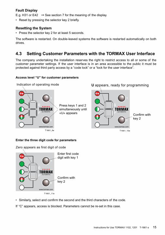
4.3 Setting Customer Parameters with the TORMAX User InterfaceThe company undertaking the installation reserves the right to restrict access to all or some of the customer parameter settings. If the user interface is in an area accessible to the public it must be protectedagainstthirdpartyaccessbya“codelock”ora“lockfortheuserinterface”.
Access level “U” for customer parameters
T1661_10e
U appears, ready for programming
Confirm withkey 2
P
T1661_11e
Zero appears as first digit of code
P
Enter first codedigit with key 1
Confirm withkey 2
T1661_9e
Indication of operating mode
Press keys 1 and 2simultaneously until«U» appearsP
Enter the three digit code for parameters
• Similarly,selectandconfirmthesecondandthethirdcharactersof thecode.
If “C”appears,accessisblocked.Parameterscannotbere-setinthiscase.

16 Instructions for Use TORMAX 1102, 1201 T-1661 e
Parameters for displays
012 Drivetype(1=1102,2=1201)
042 Firmware version
043 Number of cycles
044 Number of operating hours
Parameters for settings
10 0…E Hold open time for activator inside / outside
0 / 1/ 2 / 3 /4 / 5 / 6 / 8 /10 /12.5 /15 /17.5 /20/40/ 60 s11 0…E Hold-open time button e.g. for beds
12 0…E Hold-open time for key switch
13 0…9Delay for operating mode OFF (selection via user interface)
1/ 3 /5 / 7.5 /10 /15 /20 /30 /45 / 60 s
14 0…9 Bell active time 0 / 0.5 / 1 / 2 / 3 / 4 / 5 / 6 / 8 / 10 s
20 0…6 Opening speed10 … 100 %
21 0…6 Closing speed
30 1…3/6 Power limit when opening
Maximum depends on the drive type31 1…3/6 Power limit when closing
32 1…3/6Power limit when closing before the door is closed
38 0…6 Starting angle for Push & Go / Power Assist 1/ 2 / 3 / 5 / 8 / 12 / 16 degrees
39 0…5 Starting angle for Push & Close Maximum / 8 / 10 / 12 / 14 / 16 degrees
80 0…2 Bell trigger Activator outside / activator inside / key switch
81 0…4 Button press time (detection delay for activator) 0/1/2/3/5
91 0…4 Code lock for user interface Switched off / code 111/... 222 /… 333 /…123
Command
040 Software reset
4.4 Operation with an Operating Mode Switch uSelection of Operating ModesThe switch position defines the operating mode.
T1
30
5_4
OFF
AUTOMATIC
OPEN
Resetting the System– Change the operating mode in the event of a fault
or
– Cut off power supply to the system for at least 5 seconds.

Instructions for Use TORMAX 1102, 1201 T-1661 e 17
4.5 Operation on Power Failure
Opening a Door using a Key Switch u with a Battery Unit u• Turnthekeyswitchtothe“on”positionandholdinplaceforatleast5seconds,thenturnthekey
to the original position. Thebatteryisactivatedusingthe“wakeup”function.
Thekeyswitchmustnotremainpermanentlyinthe“on”opposition.
The door is unlocked and opened. The battery switches off again after the time programmed < by the installation engineer or when the battery is fully discharged.
If required, the operating mode can be changed on the user interface during the wake-up.
4.6 Resetting the Panic Fitting u• SelectoperatingmodeOFF(operatingmodeswitch, user interface ) or disconnect the drive from
mains (installation switch, mains plug).• Pushthedoorleaf backintotheinitialposition.• ChooseoperatingmodeAUTOMATICorswitchondriverespectively.
5 Procedure in the Event of a FaultFaults are evident from abnormal door behaviour and/or as a fault display on the user interface. Fault displaysontheuserinterfacetaketheformof aflashing“E”or“H”followedbytwofigures.
H=notification>thesystemcancontinuetobeused.
E=fault>thesystemisstationary.
Some faults or notifications can be rectified by restarting the door drive with a software reset and/or briefly(>10s)disconnectingthesystemfromthepowersupply.
Fault Display and Reset Using the TORMAX User InterfaceSee the table in section 7.1 for an overview of the fault displays.
Browse through the fault display using selector key 1 upwards (to display several faults).
1. Reset the fault display, press selector key 2 (downwards) briefly.
2. Software reset: press the key for 5 seconds.
Reset of the Fault with the Operating Mode Switch
Software reset in the event of a fault: change the operating mode.
Reset of the Fault by Disconnecting the Power SupplyIf the system does not have a battery unit, disconnect from the power supply for about 10 seconds.
If this does not reset the fault or if it re-occurs after a short time, you must arrange for the fault to be rectified by a skilled person from your TORMAX dealer. In this case note the fault number and inform the dealer. See the last page or the service tag on the system for the dealer’s address.
T1305_5
T1
30
5_4

18 Instructions for Use TORMAX 1102, 1201 T-1661 e
6 MaintenanceThe system was tested and approved by a skilled person before initial commissioning. The manufac-turer recommends that you conclude a service contract in order to maintain the value of your system for as long as possible as well as to ensure the system operates reliably and safely for a long time.
Only genuine TORMAX spare part should be used. The manufacturer accepts no liability if you fail to observe this requirement. Original spare parts and original accessories guarantee the safety of use in accordance with norm EN 16005.
The following maintenance work must be carried out:
6.1 Cleaning
Warning
Closing doors can crush – danger!
Trapped limbs can lead to serious injury.
• ThesystemmustonlybecleanedinoperatingmodeOFF,OPENorManualOperation.
• Cleancasingparts,theuserinterfaceanddoorleaveswithadampclothanda commercial cleaner.
6.2 Functional Checks
The operator must check the function and safety devices of the automatic swing door at least every three months. This will ensure that faults or hazardous changes in the system are detected atanearlystage.Seesection7.2“Check-listforFunctionalChecks”foritemstobechecked.
You should arrange for any defects detected during the routine checks to be rectified immediately by a TORMAX dealer (see the last page of this Manual for the address).
Warning
Potential switching malfunction in the automatic swing door. Potential hazards – injury caused by impact or crushing.
6.3 Maintenance and TestingMaintenance and testing should only be carried out by a trained skilled person following the manufac-turer’s instructions.
Maintenance Interval
The maintenance interval depends on the frequency of use but the system must be maintained at least once per year.
Scope of the Maintenance WorkThe content of the maintenance work is specified by the manufacturer in an inspection list.
System Test BookThe test findings are recorded after the test in the system test book. The operator must keep it in a safe place.

Instructions for Use TORMAX 1102, 1201 T-1661 e 19
7 Appendix
7.1 Fault Table
System Behaviour No. Cause Remedy/ Rectification
Note in the event of el-evated motor load.
H17 H74
Drive is heavily loaded in the open position by a soft stop or wind load.
Remove the obstruction in the re-gion of the open stop. Avoid wind load.
The door stops when opening.
H31 Electronic obstacle recognition caused by persons, wind pressure and ventilation when opening.
Remove the obstruction. Avoid drafts.
Door reverses when clos-ing.
H32 Electronic obstacle recognition caused by persons, wind pressure and ventilation when closing.
Remove the obstruction. Avoid drafts.
The door stops repeat-edly when opening. The door stands still.
H33 Electronic obstacle recognition on opening in the same position by stationary obstacle.
Remove the obstruction.
The door stops repeat-edly when closing. The door stands still.
H34 Electronic obstacle recognition on closing in the same position by sta-tionary obstacle.
Remove the obstruction.
Search run notified. H62 H67
Search run of the door after a reset or after power recovery.
Allow the search run to travel its full course.
Door remains open or is in operation again.
H71 System is in battery operation. Pause / ensure mains power supply is connected.
Door remains closed. –
E11 E12
Operating mode for example OFF, EXIT or P. The door is prevented from moving by the lock.
Motor lock will not unlock will not lock
E.g. select operating mode AUTO-MATIC. Unlock the lock. Push the door closed briefly.
Prevent wind load on the door leaf. Remove obstruction in the closed position area.
The door remains open. – Operating mode OPEN or the door is obstructed in the open position.
E.g. select operating mode AUTO-MATIC. Remove the obstruction.
The door remains closed. The door moves slowly.
E31 The safety facility in the opening direction is permanently active (>1minute)ordefective.
Remove objects from within the range of the sensor(s).
The door remains open or closed. The door moves slowly.
E32 The safety facility in the closing di-rection is permanently active (>1minute)ordefective.
Remove objects from within the range of the sensor(s).
The door does not open or does not close.
E33 The safety facility for the swing area ispermanentlyactive(>1minute)ordefective.
Remove objects from within the range of the sensor(s).
The door does not open or does not close.
E34 The stop safety facility is perma-nentlyactive (>1minute)ordefec-tive.
Remove objects from within the range of the sensor(s).
The door opens slowly. E35 E37
The safety facility in the opening direction is permanently active (>1minute)ordefective.
Remove objects from the sensor area.
The door closes slowly E36 E38
The safety facility in the closing di-rection is permanently active (>1minute)ordefective.
Remove objects from the sensor area.
The door remains open. E41 E42 E43
Activatorinsideisactive>1min. Activatoroutsideisactive>1min. Keyswitchisactive>1min.
Get sensor adjusted by a skilled person. Reset the key switch.

20 Instructions for Use TORMAX 1102, 1201 T-1661 e
System Behaviour No. Cause Remedy/ Rectification
The door remains open E45 Emergency opening is active for >1minute
Reset the command from the higher ranking system.
The door remains closed E46 Emergency closing is active for >1minute
Reset the command from the higher ranking system.
The door remains closed E47 Blocking switch active for >1minute
Reset the command from the higher ranking system.
The door remains open E48 ”Beds“sensoractivefor>1minute. Resettheswitchfor“passagewithbeds”.
The door stands still E51 Anomaly in the travel distance. Solid obstruction in the movement area.
Remove firm obstacle in the travel-ling range of the door. Perform a software-reset.
The door stands still E61 E62 E63
Power supply is overloaded or volt-age too low.
Get the power supply and connec-tions checked by a skilled person.
The door stands still E64 Drive/control system is overheated. Wait for the automatic reset after the door/control system has cooled.
Protect from direct sunlight.
The door stands still E66 Motor or output stage defective. Wedge the door open in the open position or disengage the linkage. Switch off the power supply.
Arrange for the system to be re-paired by a specialist.
The secondary door leaf remains motionless.
E99 Fault on the secondary drive. Arrange for the system to be checked by a specialist.
The door stands still. E.. E0.. E2..
Control system shut down for safety reasons.
Perform a software-reset. Arrange for the system to be re-paired by a specialist.

Instructions for Use TORMAX 1102, 1201 T-1661 e 21
7.2 Check-List for Functional Checks
Item To Be Checked Procedure Result
Sensors
T16
61_4
min. 1 m
• Walkthroughthedoordirectlyfrom the front and from different directions at normal speed, start-ing both from the inside and out-side. Activation (sensor field) at least 1 m in front of the open main closing edge.
The door opens at the right time and with sufficient speed so that passage through the door Is not hindered.
Safety Sensors
T16
61_5
min. 1 m
• Walkthroughthedoordirectlyfrom the front and from different directions at a slow speed like an infirm person, starting both from the inside and outside. Activation (sensor field) at least 1 m in front of the open main closing edge.
The door opens and remains open until you are completely through the door.
Swing Leaf, Door Frame
T1540_10
• Checktheglassdoorfillings,dooredges and rubber profiles for dam-age.
The door fillings have no sharp edges and splintered glass.
The side parts and the door seals are in place and undamaged.
Panic Fitting u
T1540_9
• Isolatethedrivefromthepowersup-ply (main system switch, mains plug) or select operating mode OFF. Then push the door in the direction opposite to the opening direction until the panic fitting releases the door leaf. Now push the door leaf back to the initial position.
The panic fitting can be released and returned to the initial position.
Mechanical Door Coordinator u
Secondary leaf
• Placethesysteminoperatingmode“P“ and open the secondary doorleaf halfway. Then allow the second-ary door leaf to close.
The primary door leaf is also pressed open by the driver flap. This leaf then remains open and motionless at about 25 degrees of the door opening until the second-ary door leaf which is closing is practically closed.

22 Instructions for Use TORMAX 1102, 1201 T-1661 e
Item To Be Checked Procedure Result
Drive, Lever and Hinges
T1540_8
• Checkthenoisesmadewhilethedoor moves.
No unusual and noticeable noise can be heard from the drive, the lever or in the region of the hinges. No significant wear is visible.
Operating Components, Lettering and Marking
3
• Checkthefunctionandmarkingof operating controls. Check all letter-ing and marking for their condition.
The operating controls are func-tioning correctly; the markings are visible and legible.
System Vicinity
T1540_7
• Checkaccesstothedoorandthemovement area of the door leaves.
Access to the door is free from objects and items likely to cause the user to trip. There are no ob-jects such as shelves, plant con-tainers and umbrella stands within a radius of 50 cm of the movement area.
Mains Power Cable
• Checkif themainspowercableisdamaged.
• If damaged,getthemainspow-er cable replaced by a skilled person.
• Checkif themainspowercableis secured against entrapping in mov-ing parts of the drive, door or sys-tem.
• If themainspowercableisnotproperly secured, get it se-cured by a skilled person.
Instructions for Use TORMAX 1102, 1201 T-1661 e 23T-1063 e Declaration of Conformity
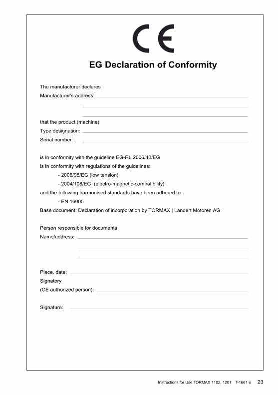
EG Declaration of Conformity
The manufacturer declares
Manufacturer’s address:
that the product (machine)
Type designation:
Serial number:
is in conformity with the guideline EG-RL 2006/42/EG
is in conformity with regulations of the guidelines:
- 2006/95/EG (low tension)
- 2004/108/EG (electro-magnetic-compatibility)
and the following harmonised standards have been adhered to:
- EN 16005
Base document: Declaration of incorporation by TORMAX | Landert Motoren AG
Person responsible for documents
Name/address:
Place, date:
Signatory
(CE authorized person):
Signature:

the passion to drive doors
TORMAX Sliding Door Drives
TORMAX Swing Door Drives
TORMAX Folding Door Drives
TORMAX Revolving Door Drives
Manufacturer: Advice, sales, installation, repairs and service:
TORMAX | CH-8180 Bülach-Zürich Phone +41 (0)44 863 51 11 Fax +41 (0)44 861 14 74 Homepage www.tormax.com E-Mail [email protected]
TORMAX is a Division and a registered trademark of Landert Motoren AG 5015
57