instructions for use - krell industries
TRANSCRIPT
Showcase ProcessorSurround
Preamp/Processor
Instructions for Use
Owner’s Reference
THE LEADER IN AUDIO ENGINEERING

Showcase ProcessorSurround Preamp/ProcessorInstructions for Usev 02.3
Krell Industries, Inc.45 Connair RoadOrange, CT 06477-3650 USA
TEL 203-799-9954FAX 203-891-2028E-MAIL [email protected] http://www.krellonline.com
This product complies with the EMC directive (89/336/EEC) and the low-voltagedirective (73/23/EEC).
© 2002 by Krell Industries, Inc. All rights reserved P/N 306040
The Showcase Processor must be placed on a firm level surface where it is notexposed to dripping or splashing.
The ventilation grids on the top and bottom of the Showcase Processor must beunobstructed at all times during operation. Do not place flammable material aboveor beneath the component.
Do not remove or bypass the ground pin on the end of the AC power cord. Thiscould cause radio frequency interference (RFI) to be introduced into your playbacksystem.
Before making connections to the Showcase Processor, make sure the back panelpower switch is off. Make sure all cable terminations are of the highest quality andfree from frayed ends, short circuits, or cold solder joints.
THERE ARE NO USER SERVICEABLE PARTS INSIDE ANY KRELL PRODUCT.Please contact your authorized Krell dealer, distributor, or Krell if you have anyquestions not addressed in this Owner’s Reference.
DTS Digital Surround ™ is a discrete 5.1 channel digital audio format available on CD, LD, and DVD soft-ware which consequently cannot be decoded and played back inside most CD, LD, or DVD players. For thisreason, when DTS-encoded software is played back through the analog outputs of the CD, LD, or DVD play-er, excessive noise will be exhibited. To avoid possible damage to the audio system, proper precautionsshould be taken by the consumer if the analog outputs are connected directly to an amplification system. Toenjoy DTS Digital Surround ™ playback, an external 5.1 channel DTS Digital Surround ™ decoder systemmust be connected to the digital output (S/PDIF, AES/EBU, or TosLink) of the CD, LD, or DVD player.
This product is manufactured in the United States of America. Krell® is a registered trademark of KrellIndustries, Inc., and is restricted for use by Krell Industries, Inc., its subsidiaries, and authorized agents. KrellSmart System Setup™ is a trademark of Krell Industries, Inc. “DTS”, “DTS Digital Surround”, “DTS ESExtended Surround”, and “Neo:6” are registered trademarks of Digital Theater Systems, Inc. TosLink is atrademark of Toshiba Corporation. Manufactured under license from Dolby Laboratories. "Dolby," "ProLogic," and the double-D symbol are trademarks of Dolby Laboratories. Confidential Unpublished Works.Copyright 1992–1997 Dolby Laboratories, Inc. All rights reserved. THX is a registered trademark ofLucasfilm, Ltd. Re-Equalization, Timbre Matching, and Decorrelation are trademarks of Lucasfilm, Ltd. Allother trademarks and trade names are registered to their respective companies.
CONTACTINFORMATION
WARNINGS

Contents
Krell Showcase Processor iii
INTRODUCTION 1
DEFINITION OF TERMS 2
UNPACKING 4
PLACEMENT 5
AC Power Guidelines 5
GETTING STARTED 6
Please Read This First 6To Select the Initial Video Signal and Format 9An Introduction to System Setup 10
FRONT PANEL DESCRIPTION 12
BACK PANEL DESCRIPTION 18
REMOTE CONTROL DESCRIPTION 22Battery Installation and Removal 22
CONNECTING THE SHOWCASE PROCESSORTO YOUR SYSTEM 27
First: Connect Analog and Digital Sources 27Next: Connect Video Sources 28Last: Connect Amplifiers and Sources 28
OVERVIEW: SYSTEM CONFIGURATION AND NAVIGATION 30
Configuration Steps 30Navigation Conventions 31
SYSTEM CONFIGURATION 32
Accessing the Main Menu 32Step 1: Configure Loudspeakers 33Step 2: Listening Room Setup 35Step 3: Calibrate Volume 36Step 4: Configure Devices 38Step 5: Configure Level Adjustment 47Step 6: Operation 55
SAVING AND RECALLING CUSTOMIZED SETTINGS AND RESTORING THE FACTORY DEFAULT SYSTEM SETTINGS 67
OPERATING THE SHOWCASE PROCESSOR 68
On/Off/Stand-by, Tape Input and Output 68Simulcast 69
APPENDIX: OPERATING MODES FORTHE SHOWCASE PROCESSOR 70
Automatically Detected Modes 70User Selectable Modes 71
WARRANTY 74
RETURN AUTHORIZATION PROCEDURE 75
SPECIFICATIONS 76-77
Page

iv Krell Showcase Processor
FIGURE 1 Front Panel Input Device Selection Buttons and Associated Factory Default Video Signals and Video Formats for North American Operation of the Showcase Processor 7
FIGURE 2 Front Panel Input Device Selection Buttons and Associated Factory Default Video Signals and Video Formats for International Operation of the Showcase Processor 8
FIGURE 3 The Showcase Processor Front Panel 11
FIGURE 4 The Showcase Processor Back Panel 17
FIGURE 5 The Showcase Processor Remote Control 21
TABLE 1 Video Signals and Video Formats Supportedby the Showcase Processor 6
TABLE 2 Factory Default Video Inputs and Standards for the Showcase Processor, North American Operation 39
TABLE 3 Factory Default Video Inputs and Standards for the Showcase Processor, International Operation 39
TABLE 4 Factory Default Digital and Analog Inputs for the Showcase Processor, North American and InternationalOperation 41
TABLE 5 Showcase Processor Audio Operating Modes 42
TABLE 6 Krell Music Surround Modes for the Showcase Processor 73
Illustrations
Tables
Page
Page

Krell Showcase Processor 1
Thank you for your purchase of the Krell Showcase Processor.
The Showcase Processor serves as the centerpiece in a KrellHEAT™—High End Audio Theater—system, which applies the fundamental principles of Krell engineering to the creation of a fullyintegrated high-performance multichannel sound system. TheShowcase Processor delivers unparalleled music and cinema sound-track reproduction through the use of a full complement of advancedKrell technologies including Smart System Setup, discrete Class A,direct-coupled circuitry with balanced outputs, user-configurable inputassignment, and broadcast-quality video circuitry.
The Showcase Processor is THX Ultra certified and features THXSurround EX, Dolby Digital 5.1, Dolby Digital EX, DTS-ES 6.1, DTSNEO:6, and Dolby Pro Logic II processing, in addition to nine propri-etary Krell Music Surround modes. This flexibility allows upgrades tosoftware via Flash memory for future surround sound formats anddesign enhancements.
The owner’s reference manual contains important information onplacement, installation, and operation of the Krell ShowcaseProcessor. Please read this information carefully. A thorough under-standing of these details helps ensure satisfactory operation of and long life for your Showcase Processor and related system com-ponents.
Introduction

2 Krell Showcase Processor
Following are the definitions of key terms used in your owner’s refer-ence manual:
BalancedA symmetrical input or output circuit that has equal impedance fromboth input terminals to a common ground reference point. The indus-try standard for professional and sound recording installations, bal-anced connections have 6 dB more gain than single-ended connec-tions and allow the use of long interconnect cables. Balanced con-nections are immune to induced noise from the system or the envi-ronment.
Single-endedA two-wire input or output circuit. Use care when using single-endedconnections as the ground connection is made last and broken first.Turn the system off prior to making or breaking single-ended connec-tions. Single-ended connections are not recommended for connec-tions requiring long cable runs.
OffWhen the power switch on the back panel is placed in the downposition and LEDs turn off, the component is off.
Stand-by ModeWhen the Showcase Processor is connected to AC power and theback panel power switch is in the up (on) position, the red stand-byLED illuminates. This indicates that the component is in stand-bymode, a low power consumption status that keeps the audio and reg-ulator circuits at idle. Krell recommends leaving the component in thestand-by mode when it is not playing music.
Operational ModeWhen the component is in the stand-by mode, and you press thepower button on the front panel or the power key on the remote control, the blue power LED illuminates. The component is in theoperational mode and is ready to play music.
Definition of Terms
INPUT AND OUTPUTCONNECTIONS
OPERATION

Krell Showcase Processor 3
Krell HEATThe Krell term HEAT, or High End Audio Theater, is a design applica-tion incorporated into Krell components to enhance multichannelhome entertainment systems. A Krell HEAT system is an integratedhome theater system consisting of a state-of-the-art Krellpreamp/processor and matching amplifiers that reproduce two chan-nel and multichannel sources with audiophile sound quality, placingthe audience in the middle of a lifelike environment.
Composite VideoAn encoded video signal that transmits luminance (Y) and color (C)information on one wire.
S-VideoVideo signal that separately transmits the luminance (Y) and color(C) components of the video signal using one wire.
Component VideoA video signal that uses three wires to convey luminance (Y), redminus luminance (R-Y), and blue minus luminance (B-Y) signals.Component video signals may be interlaced or progressive.Progressive signals build screen content in one pass rather than thetwo passes required for standard (interlaced) video. Progressivetechnology eliminates motion artifacts and produces film-quality pic-tures. Both your source and video monitor must be equipped withprogressive video technology to realize this advantage.
YPbPr One way of designating color difference signals. Y = the luminancesignal, Pb = the blue minus luminance (B-Y) signal, and Pr = the redminus luminance (R-Y) signal.
Definition of Terms, continued
TECHNOLOGY
VIDEO

Unpacking
4 Krell Showcase Processor
Open the box and remove the top layer of foam. You see theseitems:
1 Showcase Processor
1 IEC connector (AC power) cord
1 Showcase Processor handheld remote control
1 CR2025 lithium battery
1 12 VDC output (12 V trigger) cable
1 packet containing the owner’s reference manualand the warranty registration card.
Carefully remove the Showcase Processor and accessories from thebox. Remove the foam end caps and protective plastic wrap from thecomponent.
If any of these items are not included in the shipping box, please contactyour authorized Krell dealer, distributor, or Krell for assistance. Save allpacking materials. If you must ship your Showcase Processor in the future,repack the unit in its original packaging to prevent damage in transit. SeeReturn Authorization Procedure, on page 75.
Note

Krell Showcase Processor 5
Before you install the Showcase Processor into your system, reviewthe following guidelines to choose the location for the component.This will facilitate a clean, trouble-free installation.
The Showcase Processor does not require any type of special rackor cabinet for installation. For the dimensions of your ShowcaseProcessor see Specifications, on pages 76-77.
The Showcase Processor requires at least two inches (5 cm) ofclearance on each side and at least two inches (5 cm) of clearanceabove and below the component to provide adequate ventilation. Inaddition, the Showcase Processor requires at least three inches (7 cm) of clearance between other connected components. Forinstallations inside cabinetry, extra ventilation may be necessary.
The Showcase Processor has superb regulation and does notrequire a dedicated AC circuit. Avoid connections through extensioncords or multiple AC adapters. High quality 15 amp grounded ACstrips are acceptable.
High quality AC line conditioners or filters may be used if they aregrounded and meet or exceed the unit’s power supply rating of 100VA. Contact your authorized Krell dealer, distributor, or Krell beforeusing any devices designed to alter or stabilize the AC power for theShowcase Processor.
The Showcase Processor should be used only with the power cordsupplied.
Placement
AC POWER GUIDELINES

Getting Started
6 Krell Showcase Processor
The video formats and video signals of the Showcase Processorneed to match the video monitor, for the on-screen display (OSD) tobe viewable on your video monitor. The format of the video signalcan be set to either of two standards: NTSC or PAL. See Table 1and Figures 1 and 2 below.
First match the device with the appropriate factory default to yourvideo monitor’s format, NTSC or PAL, and match it to the video sig-nal used to connect the Showcase Processor to your video monitor.The device must be active in order for both the OSD information andthe menu to be visible.
North American ExampleSelect the DVD device to an NTSC video monitor and use the com-ponent video output to connect the Showcase Processor to yourmonitor.
International ExampleSelect the VCR device to a PAL video monitor and use the S-Video OSD output to connect the Showcase Processor to yourmonitor.
Table 1 Video Signals and Video Formats Supported by the Showcase Processor
PLEASE READ THIS FIRST
CommonlyLabeled
VideoSignal
CompositeS-VideoComponent
Video, CompositeS, SV, S-VideoY, Pr, Pb
ConnectorUsed
Single-ended RCADIN3 Single-ended RCA
VideoSignal
NTSC or PALNTSC or PALNTSC or PAL

Krell Showcase Processor 7
Getting Started, continued
Compo
site
3 (T
APE)
NTSC Inte
rlace
d
Compo
nent
1
NTSC Inte
rlace
d
SIGNAL
FORMATS-V
ideo
2
NTSC Inte
rlace
d
Compo
site
1
NTSC Inte
rlace
d
S-Vide
o 1
NTSC Inte
rlace
d
Compo
site
2
NTSC Inte
rlace
d
Figure 1 Front Panel Input Device Selection Buttons andAssociated Factory Default Video Signals and Video Formats,for North American Operation of the Showcase Processor
NoteFor CD, TUNER, AUX, andGAME, the factory videodefaults are disabled andtherefore a video format is not available.

8 Krell Showcase Processor
Getting Started, continued
Compo
site
3 (T
APE)
NTSC Inte
rlace
d
Compo
nent
1
NTSC Inte
rlace
d
SIGNAL
FORMATS-V
ideo
2
PAL Int
erlac
ed
Compo
site
1
NTSC Inte
rlace
d
S-Vide
o 1
NTSC Inte
rlace
d
Compo
nent
2
PAL Int
erlac
ed
Compo
site
2
PAL Int
erlac
ed
Figure 2 Front Panel Input Device Selection Buttons andAssociated Factory Default Video Signals and Video Formats,for International Operation of the Showcase Processor
NoteFor CD, TUNER, AUX, andGAME, the factory videodefaults are disabled andtherefore a video format is not available.

Krell Showcase Processor 9
Getting Started, continued
1. Connect your video monitor to the video output connectors onthe Showcase Processor that correspond to the input connectorson your video monitor. See Table 1, on page 6.
2. Power on the Showcase Processor by switching the back panelpower switch to on. Wait for the Showcase Processor to initialize.Then press the power button on the front panel.
3. Press the front panel input device selection button that matchesboth the video format and video signal compatible with your con-nected video monitor. See Figure 1 for North American operationand Figure 2 for International operation. This becomes the cur-rently selected video signal output.
4. Verify that the video monitor’s video signal input corresponds tothe Showcase Processor video signal output. Press the menukey on the remote control to verify that the OSD is now viewableon the video monitor. The system configuration main menuappears when the video format and video signals between theShowcase Processor and your video monitor are compatible.
If you have any questions regarding the selection of the video format,please call your authorized Krell dealer, distributor, or Krell.
TO SELECT THE INITIALVIDEO SIGNAL ANDFORMAT

10 Krell Showcase Processor
Getting Started, continued
The Showcase Processor provides a variety of connection and oper-ation options for outstanding music and cinema soundtrack reproduc-tion. To take full advantage of the features the Showcase Processoroffers, you’ll need to set up your system in this order:
1. Connect your Showcase Processor to the desired analog anddigital audio sources, video sources, and amplifiers. SeeConnecting the Showcase Processor to Your System, onpage 27.
2. Configure the loudspeakers, input devices, and trims using thebuilt-in, easy-to-follow system configuration menus. Step-by-stepinstructions begin on page 32, System Configuration.
3. Review the front panel, back panel, and remote control descrip-tions for information on input, and mode selections, loudspeakeradjustment, input and output connections for analog, digital, andvideo sources, and remote control operation. See pages 11-27for illustrations and descriptions.
After you’ve connected and configured your Showcase Processorand know its basic features, you’re ready to go. See Operating theShowcase Processor, on page 68.
AN INTRODUCTION TO SYSTEM SETUP

11
CD
But
ton
12 T
uner
But
ton
13 A
ux B
utto
n14
G
ame
But
ton
15 T
ape/
VC
R2
But
ton
Pro
cess
ing
Mo
de
Bu
tto
ns
and
LE
Ds
16
Ste
reo
But
ton
and
LED
17
Mod
e 1
But
ton
and
LED
18
Mod
e 2
But
ton
and
LED
19
Pro
Log
ic II
But
ton
and
LED
20
Pre
amp
But
ton
and
LED
21 T
HX
But
ton
Bas
ic O
per
atio
n1
Pow
er B
utto
n2
Pow
er L
ED
3 S
tand
-by
LED
4 In
frar
ed S
enso
r5
Infr
ared
Em
itter
Inp
ut
Dev
ice
Sel
ectio
n B
utt
on
s6
DV
D B
utto
n7
LD
But
ton
8 S
AT
But
ton
9 V
CR
But
ton
10 T
V B
utto
n
Dis
pla
y22
F
ront
Pan
el D
ispl
ay
Ind
ivid
ual
Ch
ann
el
Trim
Bu
tto
ns
23
Cen
ter
But
ton
24
Sur
r/B
ack
But
ton
25
Sub
But
ton
26
Bal
ance
But
ton
Pro
cess
or
Fu
nct
ion
B
utt
on
s27
S
ave
But
ton
28
Dire
ctio
n or
Lev
el B
utto
ns29
R
ecal
l But
ton
Figu
re 3
The
Sho
wca
se P
roce
ssor
Fro
nt P
anel
SH
OW
CA
SE
PR
OC
ES
SO
R
GA
ME
VC
RTV
TA
PE/V
CR
2
DVD
LD
SAT
CD
TU
NER
AU
X
STA
ND
-BY
PO
WER
REC
ALL
SAV
ELEVEL
TH
XB
ALA
NC
EC
EN
TER
SU
RR
/BA
CK
SU
B
PR
E A
MP
STER
EO
MO
DE 1
MO
DE 2
PR
O L
OG
IC II
611
712
813
910
2016
1718
1914
15
2126
2328
2425
2729
225
41
23

Front Panel DescriptionSee Figure 3 on page 11
12 Krell Showcase Processor
The Showcase Processor front panel provides power on and off;input, and processing mode selection; monitoring and display ofprocessor status; and balance and volume control. The front panelfeatures are described below:
1 Power ButtonThe power button switches the Showcase Processor from stand-byto the operational mode.
2 Power LEDThe blue power LED illuminates when the Showcase Processor is inthe operational mode.
3 Stand-by LEDThe red stand-by LED illuminates when the back panel power switch(51) is on, indicating that the Showcase Processor is in the stand-bymode. Krell recommends that the back panel power switch remainon at all times.
4 Infrared SensorThe infrared sensor receives commands from the ShowcaseProcessor remote control. For proper remote control operation, makesure the infrared sensor is not covered or obstructed.
5 Infrared EmitterEmits the Showcase Processor remote operation code to a learningremote. See Program Remote, on page 61.
The Showcase Processor is equipped with ten input device selectionbuttons. If properly configured, the Showcase Processor automaticallyengages the correct video and audio inputs when you press thedevice selection button.
6 DVD Button Use this button to select the digital videodisc device.
7 LD Button Use this button to select the laser disc device.
8 SAT Button Use this button to select the satellite feed device.
Basic OperationButtons
FEATURES
Input Device Selection Buttons and LEDs

Krell Showcase Processor 13
9 VCR Button Use this button to select the VCR device.
10 TV Button Use this button to select the television device.
11 CD Button Use this button to select the compact disc device.
12 Tuner Button Use this button to select the AM/FM tuner device.
13 Aux Button Use this button to select an auxiliary device, such as phono, tape, oran additional DVD, LD, CD, or VCR.
14 Game Button Use this button to select a game.
15 Tape/VCR2 Button Use this button to playback pre-recorded tapes. You may also usethis button to compare the output signal of an analog tape recorder toan audio source. See Tape Input and Output, on page 68.
Front Panel Description, continued
Input Device SelectionButtons and LEDs, continued

Front Panel Description, continued
14 Krell Showcase Processor
16 Stereo Button and LEDUse this button to select stereo decoding, which allows you to makean A/B comparison or listen to a stereo recording in two channel for-mat (left and right). The red LED illuminates when this feature isengaged.
After you select a mode, press the stereo button once. Press thestereo button again to make the A/B comparison. Press the stereobutton again to exit stereo format.
You can make an A/B comparison when you press the stereo button, only ifyou have selected a previous mode.
17 Mode 1 Button and LED18 Mode 2 Button and LEDUse these buttons to select available processing modes (such asDolby Digital, DTS, PLII Movie, THX, etc.) for incoming signals froma video or audio source.
The default mode for a signal is always stored in Mode 1. Use theMode 1 button to select the default mode. All modes that can beused for the same signal are automatically stored in Mode 2. Use theMode 2 button to scroll through these other modes. The last modedisplayed in Mode 2 is the one selected. Based on the source signal,the Showcase Processor automatically selects the correct modesavailable for the signal.
19 Pro Logic II Button and LEDUse this button to select the Dolby Pro Logic II modes for DolbySurround encoded material, including laser discs, videotapes, televi-sion broadcasts, and compact discs. The red LED illuminates whenDolby Pro Logic II decoding is selected.
These modes are selected automatically if Dolby Digital source material isencoded for Pro Logic. To turn off these modes, press the Pro Logic II but-ton.
Processing ModeButtons and LEDs
Note
Note

Krell Showcase Processor 15
20 Preamp Button and LEDUse this button to send the signal from an analog input directly to thevolume control, with no digital processing, using the analog stage ofthe preamp. This avoids possible digital signal degradation and canbe used for components such as the Krell KPS 28c Compact DiscPlayer that have a high quality signal. See Assign Analog AudioInputs, on page 43, for information on assigning the analog input toone of the device buttons (DVD, LD, SAT, VCR, TV).
This feature is only available with a signal from an analog input. If youattempt to use it with a signal from a digital input, The Showcase Processoron-screen display will read NOT ALLOWED.
21 THX ButtonUse this button to select one of the various THX modes available forthe current signal.
Front Panel Description, continued
Display
Processing Mode Buttonsand LEDs, continued
22 Front Panel DisplayThe front panel window provides status messages for ShowcaseProcessor operations, including volume and balance level, decodingmode and zone information. In addition, when a new device is selected, the physical inputs are displayed. The display turns off after60 seconds of inactivity.
Note
Individual ChannelTrim Buttons
Use the center, surr/back, and sub buttons to change taste trims (tomake temporary speaker output adjustments) of +/- 10 dB. Thesetemporary changes revert to 0 dB when a new device is selected orwhen the system is powered down. For more information on tastetrims and master (programmable) trims, see Configure LevelAdjustment, on page 47.
23 Center ButtonPress the center button, then use the direction or level buttons (28) toadjust the center loudspeaker volume.
24 Surr/Back ButtonPress the surr/back button, then use the direction or level buttons(28) to adjust the volume of the surround loudspeakers. To adjust theback loudspeakers, press the surr/back button. SURROUND TRIM
appears on the front panel display. Press the surr/back button again.BACK appears on the front panel display. Then use the direction orlevel buttons to adjust the volume of the back loudspeakers.
Front Panel Description, continued
16 Krell Showcase Processor
Individual ChannelTrim Buttonscontinued
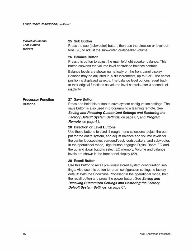
25 Sub ButtonPress the sub (subwoofer) button, then use the direction or level but-tons (28) to adjust the subwoofer loudspeaker volume.
26 Balance ButtonPress this button to adjust the main left/right speaker balance. Thisbutton converts the volume level controls to balance controls.
Balance levels are shown numerically on the front panel display.Balance may be adjusted in .5 dB increments, up to 6 dB. The centerposition is displayed as BAL 0. The balance level buttons revert backto their original functions as volume level controls after 3 seconds ofinactivity.
27 Save ButtonPress and hold this button to save system configuration settings. Thesave button is also used in programming a learning remote. SeeSaving and Recalling Customized Settings and Restoring theFactory Default System Settings, on page 67, and ProgramRemote, on page 61.
28 Direction or Level ButtonsUse these buttons to scroll through menu selections, adjust the out-put for the entire system, and adjust balance and volume levels forthe center loudspeaker, surround/back loudspeakers, and subwoofer.In the operational mode, right button engages Digital Room EQ andthe up and down buttons select EQ memory. Volume and balancelevels are shown in the front panel display (22).
29 Recall ButtonUse this button to recall previously stored system configuration set-tings. Also use this button to return configuration settings to factorydefault: With the Showcase Processor in the operational mode, holdthe recall button and press the power button. See Saving andRecalling Customized Settings and Restoring the FactoryDefault System Settings, on page 67.
Processor FunctionButtons

An
alo
g A
ud
io O
utp
uts
an
d In
pu
ts30
B
alan
ced
Ana
log
Aud
io O
utpu
ts31
S
ingl
e-en
ded
Ana
log
Aud
io O
utpu
ts32
B
alan
ced
Ana
log
Aud
io In
puts
33 T
ape
In L
eft a
nd R
ight
34 T
ape
Out
Lef
t and
Rig
ht35
V
CR
In L
eft a
nd R
ight
36
VC
R O
ut L
eft a
nd R
ight
37
Sin
gle-
ende
d A
nalo
g A
udio
Inpu
ts38
7.
1 A
udio
Inpu
ts
Dig
ital A
ud
io In
pu
ts a
nd
Ou
tpu
ts39
O
ptic
al D
igita
l Aud
io In
puts
40
Coa
xial
Dig
ital A
udio
Inpu
ts41
D
igita
l Aud
io O
utpu
ts
Vid
eo In
pu
ts a
nd
Ou
tpu
ts42
S
-vid
eo O
utpu
ts43
S
-vid
eo In
puts
44
Com
posi
te V
ideo
Out
puts
45
Com
posi
te V
ideo
Inpu
ts46
C
ompo
nent
Vid
eo O
utpu
ts47
C
ompo
nent
Vid
eo In
puts
Bac
k P
anel
Rem
ote
Co
ntr
ol C
on
nec
tion
s48
C
omm
Por
t RS
-232
Rem
ote
Con
nect
or49
R
C-5
In50
12
VD
C In
and
Out
Po
wer
Co
nn
ectio
ns
51
Bac
k P
anel
Pow
er S
witc
h52
IE
C C
onne
ctor
Figu
re 4
The
Sho
wca
se P
roce
ssor
Bac
k P
anel
23
CS
L
4
SB
L7.1 IN
PU
TS
LC
SL
SB
L
RS
WS
RS
BR
RL
L R
12
3
L R
AN
ALO
G A
UD
IO IN
PU
TS
45
67
INO
UT
TA
PE
VC
R
INO
UT
L R
L R
12
34
DIG
ITA
L A
UD
IO IN
PU
TS
RS
W
13
24
SR
SB
R
DIG
OU
T
RS
-232
MA
DE IN
US
A
RC
-5IN
50/6
0 H
z
1 2O
SD
OS
D1
2V
DC
IN
OU
T
CO
MPO
SIT
E V
IDEO
1IN
3
OS
D
S-V
IDEO
1IN
3O
UT
12V
DC
OU
T2
34
NO
USER S
ERV
ICEA
BLE P
ARTS IN
SID
E
CO
MPO
NEN
T V
IDEO
YPb
Pr
Y
3
Pb
Pr
IN
OU
T
RC
L24
SW
SR
AN
ALO
G A
UD
IO O
UTPU
TS
24
SL
SB
RS
BL1
L
PO
WER
Show
case
Pro
cessor
4746
5043
4245
4449
51
3832
3739
4030
3334
3536
4148
5231

Back Panel DescriptionSee Figure 4 on page 17
18 Showcase Processor
The back panel of the Showcase Processor provides all audio andvideo input and output connections, remote control inputs and out-puts, power on and off, and power connection. The back panel func-tions are described below.
30 Balanced Analog Audio OutputsThe Showcase Processor is equipped with eight balanced analogaudio channel outputs, with XLR connectors, for the left, center, sub-woofer, surround left, surround right, back left, and back right.
31 Single-ended Analog Audio OutputsThe Showcase Processor is equipped with eight single-ended analogaudio channel outputs, with RCA connectors, for the left, center, right,subwoofer, surround left, surround right, back left, and back right.
32 Balanced Analog Audio InputsThe Showcase Processor is equipped with one set of balancedinputs with XLR connectors.
33 Tape In Left and RightThe Showcase Processor is equipped with one set of single-endedtape inputs with RCA connectors.
34 Tape Out Left and RightThe Showcase Processor is equipped with one set of single-endedtape outputs with RCA connectors.
35 VCR In Left and RightThe Showcase Processor is equipped with one set of single-endedinputs with RCA connectors, for a VCR audio source.
36 VCR Out Left and RightThe Showcase Processor is equipped with one set of single-endedoutputs with RCA connectors, for a VCR audio source.
37 Single-ended Analog Audio InputsThe Showcase Processor is equipped with seven sets of single-ended inputs with RCA connectors.
38 7.1 Audio InputsThe Showcase Processor is equipped with eight single-ended 7.1inputs for multichannel SACD and DVD audio devices. These inputsare analog pass-through inputs.
FEATURES
Analog Audio Outputsand Inputs

Krell Showcase Processor 19
39 Optical Digital Audio InputsThe Showcase Processor is equipped with four optical digital EIAJinputs with TosLink connectors.
40 Coaxial Digital Audio Inputs The Showcase Processor is equipped with four coaxial digital audioinputs with RCA connectors.
41 Digital Audio OutputsThe Showcase Processor is equipped with two digital audio outputs:one coaxial with an RCA connector.
42 S-video Outputs The Showcase Processor is equipped with two S-video outputs withDIN connectors. The main S-video output (labeled OSD on backpanel) includes on-screen display. For dubbing purposes, the secondS-video output does not include on-screen display.
43 S-video InputsThe Showcase Processor is equipped with four S-video inputs withDIN connectors.
44 Composite Video OutputsThe Showcase Processor is equipped with two composite video out-puts with RCA connectors. The main composite video output (labeledOSD on back panel) includes on-screen display. For dubbing purpos-es, the second composite video output does not include on-screendisplay.
45 Composite Video Inputs The Showcase Processor is equipped with four RCA compositevideo inputs with RCA connectors.
46 Component Video Outputs The Showcase Processor is equipped with one set of componentvideo outputs with RCA connectors. Component video uses threewires, labeled Y, Pr, and Pb on the back panel, to convey the videosignal. These inputs are compatible with all wideband video sources.See Configure Devices, on page 38.
Back Panel Description, continued
Video Inputs and Outputs
Digital Audio Inputs and Outputs

Back Panel Description, continued
20 Krell Showcase Processor
47 Component Video Inputs The Showcase Processor is equipped with three sets of componentvideo inputs.
On-screen display (OSD) is not available for progressive component video.OSD is available for interlaced component video.
48 Comm Port RS-232 ConnectorThe Showcase Processor is equipped with an RS-232 communica-tion port, which allows you to send operational instructions directly tothe Showcase Processor using an external computer control system.
49 RC-5 InThe RC-5 input makes custom installation easy and secure byaccepting baseband RC-5 input commands from hardwired remotecontrollers.
50 12 VDC In and OutThe 12 VDC output sends a 12 Volt power on/off signal to other Krellcomponents via a 12 V trigger cable, as well as to other devices thatincorporate 12 Volt power on/off trigger input. The ShowcaseProcessor has four programmable 12 Volt outputs and one input.
When the Showcase Processor is in the operational mode and a trigger isenabled, the 12 VDC Out provides 12 V of DC output. When the ShowcaseProcessor is in the stand-by mode or off, or if a trigger is not enabled, theDC output is 0 V.
Power Connections
Video Inputs and Outputs, continued
Back Panel Remote Control Connections
Note
Note
51 Back Panel Power SwitchUse this switch to change the Showcase Processor from off to stand-by.
52 IEC ConnectorThe Showcase Processor is equipped with a standard female IECpower connector, for use with the AC power cord.

Krell Showcase Processor 21
53
75
54
78
71
56
60
66
67
70
55
59
69
65
76
74
6463
68
79
61
57
72
77
73
58
62
Power Keys53 Amp Key54 Pre Key (Power Pre Key)
Device Selection Keys55 DVD Key56 LD Key57 SAT Key58 TV Key59 CD Key60 Tuner Key61 Aux Key62 Aux 2 Key (Game Key)63 VCR Key64 Tape Key
Processing Mode Keys65 Stereo Key66 M1 Key (Mode 1 Key)67 M2 Key (Mode 2 Key)68 Pro Logic II Key69 Pre Key (Preamp Pre Key)
Control Function Keys70 Bal Key (Balance Key)71 Cntr Key72 Surr/Back Key73 Sub Key74 Prev Key75 Direction or Level Keys76 Menu Key77 Mute Key78 Enter Key79 THX Key
Figure 5 The Showcase Processor Remote Control

22 Krell Showcase Processor
The Showcase Processor remote control provides on and off, inputselection, processing mode selection, speaker volume and balanceadjust, and mute functions, as well as access to the system configu-ration menu.
The Showcase Processor remote control uses one CR2025 lithiumbattery, which is included with the shipment.
To open the battery compartment on the back of the remote control:
1. Place the remote face down on the table.
2. Use your thumbnail or a small jeweler’s or eyeglass screwdriverto move the small tab toward the center of the remote, whileusing your index fingernail or screwdriver to pull down gently onthe slot to the right of the tab. The battery compartment will slideout.
3. Place the battery, plus side up, in the battery tray.
4. Slide battery compartment back into the remote until you hear aclick.
The remote control is ready for operation.
Do not use a knife or other sharp objects to open the battery compartment;they will scratch the remote control finish.
Replace batteries when remote control function becomes intermittent.
Remove batteries if the remote control is not to be used for a long period oftime. Battery leakage can damage the remote control.
Remote Control DescriptionSee Figure 5 on page 21
BATTERYINSTALLATIONAND REMOVAL
Notes

Remote Control Description, continued
Krell Showcase Processor 23
Device Selection Keys 55 DVD KeyUse this key to select the digital videodisc device.
56 LD Key Use this key to select the laser disc device.
57 SAT Key Use this key to select the satellite source device.
58 TV Key Use this key to select the television device.
59 CD Key Use this key to select the compact disc device.
60 Tuner Key Use this key to select the AM/FM tuner device.
61 Aux Key Use this key to select the auxiliary device, such as phono, tape, or anadditional DVD, LD, CD, or VCR.
62 Aux 2 Key (Game Key) Use this key to select a game.
63 VCR Key Use this key to select the VCR device.
64 Tape Key Use this key to select the output from an analog tape recorder con-nected to the tape inputs.
Showcase Processor remote control keys and their functions aredescribed below:
53 Amp KeyUse this key to power on/off a Krell remote control amplifier.
54 Pre Key (Power Pre Key)Use this key to switch the Showcase Processor between the stand-bymode and the operational mode.
FEATURES
Power Keys

Remote Control Description, continued
24 Krell Showcase Processor
Note
65 Stereo KeyUse this key to select stereo decoding, which allows you to make anA/B comparison or listen to a stereo recording in two channel format(left and right). The red LED illuminates when this feature is engaged.
After you select a mode, press the stereo button once. Press thestereo button again to make the A/B comparison. Press the stereobutton again to exit stereo format.
You can make an A/B comparison when you press the stereo button, only ifyou have selected a previous mode.
66 M1 Key (Mode 1 Key)67 M2 Key (Mode 2 Key)Use these keys to select available processing modes (such as DolbyDigital, DTS, PLII Movie, THX, etc.) for incoming signals from a videoor audio source.
The default mode for a signal is always stored in Mode 1. Use theMode 1 key to select the default mode. All other modes that can beused for the same signal are automatically stored in Mode 2. Use theMode 2 key to scroll through these other modes. The last mode dis-played in Mode 2 is the one selected. Based on the source signal,the Showcase Processor automatically selects the correct modesavailable for the signal.
68 Pro Logic II KeyUse this button to select the available Dolby Pro Logic II modes forDolby Surround encoded material, including laser discs, videotapes,television broadcasts, and compact discs. The red LED illuminateswhen the Showcase Processor is in the Dolby Pro Logic II decodingmode.
This mode is selected automatically if Dolby Digital source material isencoded for Pro Logic. To turn off this mode, press the Pro Logic II key.
Processing Mode Keys
Note

Remote Control Description, continued
Krell Showcase Processor 25
69 Pre Key (Preamp Pre Key)Use this button to send the signal from the analog input directly tothe volume control, with no digital processing, using the analog stageof the preamp. This avoids possible digital signal degradation andcan be used for components such as the Krell KPS 28c CompactDisc Player that have a high quality signal. See Assign AnalogAudio Inputs, on page 43, for information on assigning the analoginput to one of the device buttons (DVD, LD, SAT, VCR, TV).
This feature is only available with a signal from an analog input. If youattempt to use it with a signal from a digital input, the Showcase Processoron-screen display will read NOT ALLOWED.
70 Bal Key (Balance Key)Press and hold this key to convert the volume level controls to bal-ance controls. See Balance Button (26), on page 16.
Use the center, surr/back, and sub keys to change taste trims (to maketemporary loudspeaker output adjustments) of +/- 10 dB. These temporarychanges revert to 0 dB when a new device is selected or the system ispowered down. For more information on taste trims and master (program-mable) trims, see Configure Level Adjustment, on page 47.
71 Cntr Key Use this key to select the center loudspeaker, then use the directionkeys (75) to adjust volume.
72 Surr/Back KeyUse this key to select the surround and/or back loudspeakers, thenuse the direction keys (75) to adjust the volume of the surround loud-speakers. To adjust the back loudspeakers, press the surr/back but-ton. SURROUND TRIM appears on the front panel display (23). Press thesurr/back button again. SURR/BACK appears on the front panel display.Then use the direction keys (75) to adjust the volume of the backloudspeakers.
73 Sub KeyUse this key to select the subwoofer, then use the direction keys (75)to adjust volume.
Control Function Keys
Note
Note
Processing Mode Keys,continued

Remote Control Description, continued
26 Krell Showcase Processor
74 Prev KeyUse this key to escape from a system configuration on-screen menuto the previously displayed screen.
75 Direction or Level KeysUse these keys to scroll through menu selections, adjust the outputfor the entire system, and adjust balance and volume levels for thecenter loudspeaker, surround/back loudspeakers, and subwoofer.Volume and balance levels are shown in the front panel display (23).
76 Menu KeyUse this key to access the system configuration on-screen menus.
77 Mute KeyUse this key to mute the output of the Showcase Processor. VOLUME
MUTE appears in the front panel display (23).
78 Enter KeyUse this key to accept configuration menu selections, accept an inputdevice selection, or to display current system conditions.
79 THX KeyUse this key to select of the various THX modes available for the current signal.
Control Function Keys, continued

First:Connect Analog and Digital Sources
FOLLOW THESE CONNECTION STEPS
Connecting the Showcase Processorto Your System
Krell Showcase Processor 27
This section provides information about connecting the ShowcaseProcessor to analog and digital sources, video sources, and ampli-fiers. The Showcase Processor is equipped with balanced and sin-gle-ended inputs.
Krell recommends using balanced interconnect cables. Balancedinterconnect cables not only can minimize sonic loss but also areimmune to induced noise, especially for installations using longcables. Balanced connections have 6 dB more gain than single-ended connections. When level matching is critical, keep this specifi-cation in mind. Krell recommends that you use balanced inputs forcomponents that will use the preamp mode.
Follow these steps to connect the Showcase Processor to your system:
1. Make sure all power sources and components are off before connecting inputs and outputs.
2. Neatly arrange and organize wiring to and from the ShowcaseProcessor and all components. Separate AC wires from audiocables to prevent hum or other unwanted noise from being intro-duced into the system.
3. For stereo analog input sources, connect the right and left out-puts of your source components to the inputs on the ShowcaseProcessor. The Showcase Processor is equipped with nine setsof single-ended analog audio inputs (37) (S-1 through S-7, tape,and VCR) via RCA connectors and one set of balanced analogaudio inputs (32) via XLR connectors.
For multichannel analog sources (for example, multichannelSACD and DVD audio players), connect the outputs of yoursource component to the 7.1 inputs (38) on the back panel.
4. For digital audio sources, connect the digital audio output of your source components to the digital inputs on theShowcase Processor. The Showcase Processor is equippedwith four coaxial digital audio inputs (40) via RCA connectorsand four digital EIAJ optical inputs (39) via TosLink connectors.
See Please Read This First, on page 6, for information on making the on-screen display visible on your video monitor.
Note

28 Krell Showcase Processor
1. Connect the video source outputs to the appropriate video inputson the Showcase Processor.
2. Connect the video outputs of the Showcase Processor to theinputs of your video monitor and/or video recorder.
Component video signals use three wires that convey luminance (Y), red minus luminance [R – Y] (Pr), and blue minus luminance [B – Y] (Pb) signals.
Use the component connection when the source device (DVD) andoutput device (TV) both feature component connections. See theuser manuals included with these devices for more information.
The Showcase Processor is also equipped with four S-video inputs(43) and four composite video inputs (45). S-video cables transmitthe color and luminance components of the video signal separately.
The Showcase Processor is equipped with two S-video outputs (42),two composite video outputs (44), and one set of component videooutputs. One S-video output, one composite video output, and thecomponent video output include on-screen display (OSD). For dub-bing purposes, only the S-video and composite outputs labeled OSDdisplay on screen information.
S-video inputs can be seen only on S-video outputs. The same is true forcomposite and component video signals.
The Showcase Processor has balanced outputs with XLR connec-tors and single-ended outputs with RCA connectors. Both outputs areactive at all times, allowing simultaneous connection to separateamplifiers. Only one of these output formats should be connected toa single amplifier.
1. Connect the outputs of the Showcase Processor to the input(s) ofyour power amplifier(s).
2. Connect source devices to the appropriate inputs on the backpanel.
3. Connect the AC power cord to the IEC connector (52) on theShowcase Processor and to the AC wall receptacle.
Connecting the Showcase Processor to Your System, continued
Note
Next:Connect Video Sources
Last:Connect Amplifiers and Sources
Krell Showcase Processor 29
4. Move the back panel power switch (51) into the up (on) position.The red power LED on the front panel illuminates. The wordsPLEASE WAIT, INITIALIZING appear in the front panel display (25). Whenthe initializing message disappears, the Showcase Processor isready to switch to the operational mode.
5. Use either the front panel power button (1) or the remote con-trol power pre key (54) to power on the Showcase Processor.The blue power LED (2) on the front panel illuminates. TheShowcase Processor is now in the operational mode and readyto be configured.
Make sure that any source devices are off when you configure theShowcase Processor.
Connecting the Showcase Processor to Your System, continued
Last:Connect Amplifiers and Sources, continued
IMPORTANT

Overview: System Configuration and Navigation
30 Krell Showcase Processor
This section briefly outlines the configuration menus and introducesyou to the navigational features of the menus.
The easy-to-follow, step-by-step configuration menus let you set upyour Showcase Processor for optimum performance. Detailedinstructions begin on page 32. Krell recommends that you configureyour component in the following order:
1. CONFIGURE SPEAKERSThe configure speaker menu lets you tell the Showcase Processorhow many and what type of loudspeakers are in your system andallows you to select the bass range for each loudspeaker. It alsoallows you to control the subwoofer output and set the crossoverfrequency.
2. LISTENING ROOM SETUPThe listening room setup menu lets you define the exact location ofeach loudspeaker in the system, so that the Showcase Processorcan synchronize the output to all speakers, no matter where they arelocated in the room.
3. CALIBRATE VOLUMEThe calibrate volume menu lets you set the volume to a referenceevel, to match the sensitivities of different loudspeakers and ampli-fiers in your system.
4. CONFIGURE DEVICESThe configure devices menu lets you assign each device’s inputsand configure modes and triggers.
5. CONFIGURE LEVEL ADJUSTMENTThe configure level menu lets you set master volume trims for thecomponents in your system. These fixed positive or negative volumeoffsets let you maintain level matching while switching betweeninputs with different output levels.
6. OPERATION The operation menu lets you select screen background color, posi-tion and display time for on-screen display, set audio operation, pro-gram a learning remote control, and adjust frequency response usingthe Krell Digital Room Equalizer.
CONFIGURATIONSTEPS
For best results, followthese steps
NAVIGATIONCONVENTIONS
Overview: System Configuration and Navigation, continued
Krell Showcase Processor 31
When a menu screen first appears, and there is a cursor blinking atone menu item, press the enter key (75) to select the menu item. Ifthe item is configurable, the entire selection blinks along with the cur-sor.
Then use the direction keys (75) to scroll through the options that areblinking. Press the enter key to set your selection. After you have setthe selection, the selection stops blinking and only the cursor at themenu item is blinking. Use the direction keys to move the cursor tothe next menu item.
The remote control is the main input device for configuring theShowcase Processor. For all system options, use the following keys tonavigate through the configuration menu screens:
82 Menu Key Press this key once to enter the configuration menu. The front paneldisplay reads MENU MODE. The MAIN MENU screen appears.
Press this key again to exit the configuration menu. The ShowcaseProcessor reverts to the operational mode.
81 Direction or Level KeysPress these keys to scroll line by line through options on a menuscreen. After pressing enter (84), press the direction or level keyagain to scroll through options within a single line.
84 Enter KeyPress this key once to select a highlighted item. Once an item isselected, use the direction or level keys (81) to scroll through avail-able options within a line. To select a highlighted option within a line,press the enter key again.
80 Prev KeyPress this key once to return to the previous screen within the config-uration menu.
54 Pre Key (Power Pre Key)Press this key once to exit the configuration menu. The ShowcaseProcessor reverts to the stand-by mode.
To Select and EnterMenu Items

32 Krell Showcase Processor
The Showcase Processor is shipped with factory default selections inthe configuration menus. For correct operation and maximum perfor-mance, the Showcase Processor needs to be configured for each sys-tem device, its capabilities, and loudspeaker positions in the listeningroom.
To save your new configuration menus, or revert to the factorydefaults, see Saving and Recalling Customized Settings, andRestoring the Factory System Settings, on page 67.
Krell recommends configuring your system step-by-step, in thesequence described below. Enter information into the ShowcaseProcessor through the interactive on-screen menus. These menusare structured to guide you through the setup process for eachdevice, or for your entire surround sound system.
System Configuration
Press the menu key. The front panel display reads MENU MODE. TheMAIN MENU screen appears.
ACCESSING THE MAIN MENU
Main Menu Screen
SHOWCASE-MAIN MENU-
�� CONFIGURE SPEAKERS ��LISTENING ROOM SETUP
CALIBRATE VOLUMECONFIGURE DEVICES
CONFIGURE LEVEL ADJUSTMENT
OPERATION
How To Navigate the Menu and Make a Selection
1. Use the direction keys to scrollfrom line to line.
2. Press enter to select a line.3. Use the direction keys to scroll
through options within a line. 4. Press enter to select and set
an option.5. Use the direction keys to scroll
to the next line.

Krell Showcase Processor 33
System Configuration, continued
The first option on the main menu screen, CONFIGURE SPEAKERS, letsyou tell the Showcase Processor how many and what type of loud-speakers are in your system and select the bass range for each loud-speaker. It also allows you to control the subwoofer output and setthe crossover frequency.
Select CONFIGURE SPEAKERS on the MAIN MENU. The SPEAKER SETUP
screen appears.
If you have a 5.1 system, select NO back speakers. If you have a 6.1system, select 1 back speaker. If you have a 7.1 system, select 2back speakers.
When 1 back speaker is selected, the signal is present at the left back output.
STEP 1CONFIGURE LOUDSPEAKERS
Speaker Setup Screen
SHOWCASE-SPEAKER SETUP-
YESYES2YES
FRONTCENTERSURROUNDBACKSUBCRSOVR5.1 SURR
�� FULL RANGE �� FULL RANGE FULL RANGE FULL RANGE
NORMAL 80 Hz
SURROUND
Note

34 Krell Showcase Processor
Using this screen, you can enable loudspeakers that are in your sys-tem in the left column and select loudspeaker characteristics in thefar right column.
FULL RANGE
FULL RANGE sends 20Hz to 20KHz signals to the loudspeaker. LIMITED
sends information from the crossover frequency (see below) to20KHz to the loudspeaker. The frequencies below the crossover fre-quency are sent to the subwoofer if present; otherwise, these low fre-quencies are sent to the full range loudspeakers in the system.
SUB
Select NORMAL or ENHANCED to choose the amount of bass informationsent to the subwoofer. NORMAL sends the low frequencies from thelimited speakers and the .1 (or LFE) signal to the subwoofer.ENHANCED sends additional bass information from the left and rightloudspeakers to the subwoofer in addition to the low frequenciesfrom the limited loudspeakers and the .1 (or LFE) signal.
CRSOVR
Crossover selections are 120, 100, 80, 60, and 40 Hz. The standardcrossover setting is 80 Hz. Choose the crossover frequency appropri-ate for your loudspeakers. The frequencies below the crossover frequency are sent to the subwoofer if a subwoofer is present; other-wise, these low frequencies are sent to the full range loudspeakers inthe system.
5.1 SURR
Select SURROUND, BACK, or BOTH to choose which loudspeakers in a6.1 or 7.1 system receive surround information when playing a DolbyDigital 5.1 or DTS 5.1 encoded software. SURROUND sends surroundchannel information to your surround loudspeakers only. BACK sendssurround channel information to your back loudspeakers only. BOTH
sends surround channel information to your surround and back loud-speakers simultaneously.
After selecting the appropriate loudspeaker configuration for yoursystem, press the previous key (74) twice to return to the main menu.
System Configuration, continued
Speaker Setup Screen, continued
How To Navigate the Menu and Make a Selection
1. Use the direction keys to scrollfrom line to line.
2. Press enter to select a line.3. Use the direction keys to scroll
through options within a line. 4. Press enter to select and set
an option.5. Use the direction keys to scroll
to the next line.

Krell Showcase Processor 35
System Configuration, continued
The second option on the main menu screen, ROOM SETUP, allows youto tell the Showcase Processor the exact location of each loudspeak-er in your system.
Select LISTENING ROOM SETUP on the MAIN MENU. The ROOM SETUP screenappears:
STEP 2LISTENING ROOMSETUP
Room Setup Screen
When you access the ROOM SETUP screen, the cursor is blinking at theLEFT loudspeaker. Use the direction and enter keys to navigate thescreen, select loudspeakers, and enter the correct distance (0 to 30feet) from the main listening position to the loudspeaker. After all thedistances are set, press the previous key twice to return to the mainmenu.
Any speaker not configured in the SPEAKER SETUP menu displays N/A (notavailable) on the ROOM SETUP screen.
Note
SHOWCASE-ROOM SETUP-
�� LEFT ��0 FT
L SURR0 FT
L BACK0 FT
CENTER0 FT
SUB0 FT
C BACK N/A
RIGHT0 FT
R SURR0 FT
R BACK0 FT

36 Krell Showcase Processor
The third option on the main menu screen, CALIBRATE VOLUME, allowsyou to calibrate each channel using the internal noise generator ofthe Showcase Processor.
A sound pressure level (SPL) meter is required for this procedure.
Select CALIBRATE VOLUME on the MAIN MENU. The CALIBRATE ROOM SETUP
screen appears:
Press the enter key to choose AUTO NOISE SEQUENCE. The AUTO
CALIBRATION screen appears:
System Configuration, continued
Calibrate Room Setup Screen
Auto Noise Sequence
Auto Calibration Screen
Note
SHOWCASE-CALIBRATE ROOM SETUP-
SELECT THE CALIBRATIONMETHOD
�� AUTO NOISE SEQUENCE ��MANUAL NOISE SEQUENCE
PROGRAM MATERIAL
SHOWCASE-AUTO CALIBRATION-
LEFT�� 0 DB ��
L SURR0 FT
L BACK0 FT
CENTER0 DB
SUB0 DB
C BACKN/A
RIGHT0 DB
R SURR0 DB
R BACK0 FT
STEP 3CALIBRATE VOLUME
How To Navigate the Menu and Make a Selection
1. Use the direction keys to scrollfrom line to line.
2. Press enter to select a line.3. Use the direction keys to scroll
through options within a line. 4. Press enter to select and set
an option.5. Use the direction keys to scroll
to the next line.
Krell Showcase Processor 37
Set the SPL meter to C weighting and slow response. After initializ-ing, the LEFT channel dB setting on the screen blinks, and you hearband limited white noise through the left loudspeaker. This noise con-tinues for two seconds and then moves clockwise to the next loud-speaker in the system.
While the individual channel on screen is blinking, use the directionkeys to adjust each loudspeaker’s setting until the SPL meter reads75 dB.
Repeat this process with the remaining loudspeakers. When all theloudspeakers are adjusted, press the previous key twice to return tothe main menu screen.
The adjustments must be made while the channel on screen is blinking.
Set the SPL meter to C weighting and slow response. After initializ-ing, the cursor at the LEFT channel dB setting on the screen blinks.Press enter. You hear banded white noise through the left loudspeaker.
While the individual channel on screen is blinking, use the directionkeys to adjust each loudspeaker’s setting until the SPL meter reads75 dB.
Press enter to set each selection, then use the direction keys tomove to the next loudspeaker.
Repeat this process for all loudspeakers. Press the previous keytwice to return to the main menu screen.
Any speaker not configured in the SPEAKER SETUP menu displays N/A (notavailable) for the dB specification.
The program material option uses the same screen as the automaticor manual noise sequence, but requires external program materialsuch as a test disc. The source plays, simultaneously, from all config-ured loudspeakers. Use the enter and direction keys to individuallyadjust loudspeaker levels based on your listening preferences ratherthan SPL readings. If all channels are not present in the sourcematerial, they will not be heard during this process.
System Configuration, continued
Manual Noise Sequence
Program MaterialOption
STEP 3CALIBRATE VOLUMEcontinued
Note
Note

To help you understand the numerous configuration options availablethrough the Showcase Processor, Step 4 illustrates configuring aspecific source device: a DVD player.
To configure other source devices, Krell recommends that you config-ure one device at a time, using the menu’s step-by-step format.
Some Showcase Processor configurations are designed for digitalonly, and some are designed for analog only. If you try to format ananalog source device using a digital configuration, the menu will notlet you proceed.
IMPORTANT
38 Krell Showcase Processor
System Configuration, continued
Please read before continuing on to Step 4
STEP 4CONFIGURE DEVICES
The fourth option on the main menu screen, CONFIGURE DEVICES,
allows you to assign video and audio inputs to source devices andconfigure triggers for devices in the system.
Select CONFIGURE DEVICES on the MAIN MENU. The CONFIGURE DEVICES
screen appears:
Configure Devices Screen
SHOWCASE-CONFIGURE DEVICES-
�� CONFIGURE VIDEO ��CONFIGURE AUDIO
CONFIGURE TRIGGER
How To Navigate the Menu and Make a Selection
1. Use the direction keys to scrollfrom line to line.
2. Press enter to select a line.3. Use the direction keys to scroll
through options within a line. 4. Press enter to select and set
an option.5. Use the direction keys to scroll
to the next line.

Krell Showcase Processor 39
System Configuration, continued
The Showcase Processor is shipped with separate factory defaultvideo inputs and standards for North American and internationaloperation. See Table 2 and Table 3 below.
Table 2 Factory Default Video Inputs andStandards for the Showcase Processor, North American Operation
Please read before assigning video inputs
Table 3 Factory Default Video Inputs andStandards for the Showcase Processor, International Operation
Device Video StandardAssigned Input
Component 1Composite 1S-Video 1S-Video 2Composite 2DisabledDisabledDisabledComponent 2Composite 3
NTSC InterlacedNTSC InterlacedNTSC InterlacedNTSC InterlacedNTSC InterlacedN/AN/AN/ANTSC InterlacedNTSC Interlaced
DVDLDSATVCRTVCDTunerAux 1Aux 2 (Game)Tape
Device Video StandardAssigned Input
Component 1Composite 1S-Video 1S-Video 2Component 2Composite 2DisabledDisabledComponent 2Composite 3
NTSC InterlacedNTSC InterlacedNTSC InterlacedPAL InterlacedPAL InterlacedPAL InterlacedN/AN/ANTSC InterlacedNTSC Interlaced
DVDLDSATVCRTVCDTunerAux 1Aux 2 (Game)Tape
Video factory defaults for the Showcase Processor do not need to bechanged if your system matches the factory defaults.
Note

40 Krell Showcase Processor
System Configuration, continued
The ASSIGN VIDEO INPUT screen lets you select the device to configureand assign an input to the device. Assigned inputs correspond to theinputs on the back panel. For devices that do not use a video input,for example, a CD player, there are two options: PREVIOUS or DISABLED.PREVIOUS allows the last active video input to continue tobe displayed, as long as a previous selection has been made. DISABLED turns off the video outputs.
You may also choose a standard video format, either NTSC or PAL,
and select whether the component signals are INTERLACED or PROGRESSIVE/HD, depending upon your video source and monitorcapabilities.
Use the direction and enter keys (75) to navigate the menu and setselections. When all selections are entered, press the previous key (74) once to return to the CONFIGURE DEVICES menu.
Assign Video Input Screen
Assign Video Input
SHOWCASE-ASSIGN VIDEO INPUT-
DEVICE �� DVD ��
ASSIGN INPUTCOMPONENT 1
VIDEO STANDARDNTSC INTERLACED
Select CONFIGURE VIDEO from the CONFIGURE DEVICES menu. The ASSIGN
VIDEO INPUT screen appears:
How To Navigate the Menu and Make a Selection
1. Use the direction keys to scrollfrom line to line.
2. Press enter to select a line.3. Use the direction keys to scroll
through options within a line. 4. Press enter to select and set
an option.5. Use the direction keys to scroll
to the next line.

System Configuration, continued
Please read beforeconfiguring audio and digital inputs
The Showcase Processor is shipped with factory defaults for analogand digital inputs. These defaults are the same for domestic andinternational operation, and are listed in Table 4 below:
Table 5, on the next page, shows the audio operating modes avail-able with the Showcase Processor. See also Appendix: OperatingModes for the Showcase Processor, on page 70, for descriptions ofoperating modes listed in Table 5.
Table 4 Factory Default Digital and Analog Audio Inputs for the Showcase Processor, North American and International Operation
Krell Showcase Processor 41
Device Configuration OptionsAssigned Input
Coax 1
Coax 2
Opt 1
Disabled
Disabled
Disabled
Disabled
Disabled
Opt 2
Disabled
DVD
LD
SAT
VCR
TV
CD
Tuner
Aux 1
Aux 2(Game)
Tape
Dolby Digital 5.1 DTS 5.1 PCM
AnalogDigital Analog
Dolby Digital 2.0
Digital
S1
S2
S3
VCR
S4
B1
S5
7.1 Input
S6
Tape
Dolby D 5.1
Dolby D 5.1
Dolby D 5.1
N/A
N/A
N/A
N/A
N/A
Dolby D 5.1
N/A
Dolby D +Dolby PLII Movie
Dolby D +Dolby PLII Movie
Dolby D +Dolby PLII Movie
N/A
N/A
N/A
N/A
N/A
N/A
N/A
DTS 5.1Movie
DTS 5.1Movie
DTS 5.1Movie
N/A
N/A
N/A
N/A
N/A
DTS 5.1
N/A
Dolby PLIIMovie
Dolby PLIIMovie
Dolby PLIIMovie
N/A
N/A
N/A
N/A
N/A
Dolby PLIIMovie
N/A
Dolby PLIIMovie
Dolby PLIIMovie
Dolby PLIIMovie
Dolby PLIIMovie
Dolby PLIIMovie
Preamp
Preamp
N/A
Preamp
Preamp
Note Audio factory defaults for the Showcase Processor do not need to be con-figured if your system matches the factory defaults.

42 Krell Showcase Processor
System Configuration, continued
Table 5 Showcase Processor Audio Operating Modes
Dolby Digital 5.1
DTS 5.1
Analog Signal
Dolby Digital 2.0
Digital Signals (4 formats)Possible DefaultOperatingModes
PCM
——————————————
YESYESYESYES————————————
——————————————
——————
YESYESYESYESYESYESYES————————————————————
——————————————
——————
——————————————————————————————————
YESYESYESYES——————
——————
——————————————————————
YESYESYESYESYESYES
————————
YESYESYES
YESYESYES
Dolby D + PLII MovieDolby D + PLII Movie + THXDolby D + PLII MusicDolby D + PLII MatrixDolby D + Dolby Pro LogicDolby D + Pro Logic + THXDolby D 2.0Dolby D 5.1Dolby Digital EX1
Dolby D 5.1 + THXDolby D 5.1 + THX Surr EX1
Dolby PLII MovieDolby PLII Movie + THXDolby PLII MusicDolby PLII MatrixDolby Pro LogicDolby Pro Logic + THX
DTS 5.1 Movie 3
DTS 5.1 Movie + THX3
DTS 5.1 Music 3
DTS 5.1 Only2, 3
DTS Neo:6 Cinema DTS Neo:6 Cinema + THXDTS Neo:6 Music
Krell Music SurroundPreampStereo
——————————————————————
YESYESYESYESYESYES
————————
YESYESYES
YES——
YES
1 The DOLBY DIGITAL EX and DOLBY D 5.1 + THX SURR EX operating modes are available only when your system has 6 or 7 channels.
2 DTS 5.1 ONLY sets an input to receive only DTS 5.1 information. When this mode is selected, you are unable to select a default mode for PCM, Dolby Digital 2.0, and Dolby Digital 5.1 signals; the input will playback only DTS 5.1 material.
3 When the Showcase Processor detects a DTS 5.1 signal and engages the default mode selected for a DTS 5.1 signal, DTS-ES MATRIX 6.1 and DTS-ES MATRIX 6.1 + THX are accessible by pressing the M2 button or key. The DTS-ES
MATRIX 6.1 operating mode is available only when your system has 6 or 7 channels.
Note The DOLBY DIGITAL EX, DOLBY D 5.1 + THX SURR EX, DTS-ES DISCRETE 6.1, and-DTS-EX MATRIX 6.1 operating modes are available only when your system has6 or 7 channels.

Krell Showcase Processor 43
Select ANALOG. The ASSIGN ANALOG AUDIO INPUT screen appears.
Use the direction and enter keys to scroll through and select thedevice you want to configure, select the MIGRATION/REC input, andchoose the analog mode, if mode options are available.
System Configuration, continued
Assign Analog Audio Input Screen
SHOWCASE-ASSIGN ANALOG AUDIO INPUT-
DEVICEAUTO-MIGRATION
�� DVD ��ON
MIGRATION/REC INPUTS1
ANALOG MODEPREAMP
Select CONFIGURE AUDIO from the CONFIGURE DEVICES menu. The ASSIGN
AUDIO INPUTS screen appears:Assign Analog AudioInputs
Assign Audio Inputs Screen
SHOWCASE-ASSIGN AUDIO INPUTS-
ANALOGDIGITAL
How To Navigate the Menu and Make a Selection
1. Use the direction keys to scrollfrom line to line.
2. Press enter to select a line.3. Use the direction keys to scroll
through options within a line. 4. Press enter to select and set
an option.5. Use the direction keys to scroll
to the next line.
44 Krell Showcase Processor
After the selections for analog audio inputs are entered, press theprevious key. You return to the ASSIGN AUDIO INPUTS screen. Select DIGITAL. The ASSIGN DIGITAL AUDIO INPUT screen appears.
Use the direction and enter keys to scroll through and select the digi-tal device you want to configure, select the digital input, and choosethe default mode for the four major surround sound digital formats:Dolby Digital 2.0, Dolby Digital 5.1, DTS 5.1, and PCM. Each ofthese signals has options under DEFAULT MODE. If a THX Surround EXor DTS ES encoded disc is played, the Showcase Processor willautomatically select one of these modes.
The digital input must be set to DISABLED to use the analog input.and it mustbe set to DISABLED to use preamp mode.
PREVIOUS holds the last selected digital input.
The DOLBY DIGITAL EX, DOLBY D 5.1 + THX SURR EX, DTS-ES DISCRETE 6.1, and-DTS-EX MATRIX 6.1 operating modes are available only when your system has6 or 7 channels.
When the device is configured, press the previous key (74) twice toreturn to the CONFIGURE DEVICES menu.
System Configuration, continued
Assign Digital AudioInputs
SHOWCASE-ASSIGN DIGITAL AUDIO INPUT-
DEVICEDIGITAL INPUT
�� DVD ��COAX 1
INCOMING SIGNALPCM
DEFAULT MODEDOLBY PL II MOVIE
Notes
Assign Digital Audio Input Screen
Assign Analog Audio Inputs, continued
AUTO-MIGRATION ON allows the Showcase Processor to switch to theanalog input automatically, a feature that is particularily useful forSACD players.
The analog signal must be assigned, not DISABLED, in order for auto-migration to be active.

Krell Showcase Processor 45
The final option on the CONFIGURE DEVICES menu is CONFIGURE TRIGGER.
This option allows you to customize the operation of the four remoteoutput 12 VDC (12 Volt trigger) connectors (54) on the back panel.
Select CONFIGURE TRIGGER from the CONFIGURE DEVICES menu. The CONFIGURE TRIGGER screen appears:
Use the direction and enter keys to select the source device, the trigger(s) you want to configure, and the mode and delay for eachtrigger you select. The delay is only available when a trigger is setto ENABLED. There is a three second delay after you select ENABLED,
before the trigger turns on. The trigger turns off immediately whenyou select DISABLED.
System Configuration, continued
Configure Trigger
SHOWCASE-CONFIGURE TRIGGER-
MODEENABLED
�� DVD ��
TRIGGER 1
DELAYN/A
Configure Trigger Screen
How To Navigate the Menu and Make a Selection
1. Use the direction keys to scrollfrom line to line.
2. Press enter to select a line.3. Use the direction keys to scroll
through options within a line. 4. Press enter to select and set
an option.5. Use the direction keys to scroll
to the next line.
46 Krell Showcase Processor
For any of the other devices available [LD, SAT, VCR1, TV, CD, TUNER, AUX1,
AUX2 (GAME), TAPE], use the same process outlined above. Krell recom-mends that you use the step-by-step menu to configure each devicecompletely, then configure the next device.
When you have configured all the devices you want the ShowcaseProcessor to recognize, press the previous button (74) twice to returnto the main menu.
System Configuration, continued
Configuring AdditionalInputs
How To Navigate the Menu and Make a Selection
1. Use the direction keys to scrollfrom line to line.
2. Press enter to select a line.3. Use the direction keys to scroll
through options within a line. 4. Press enter to select and set
an option.5. Use the direction keys to scroll
to the next line.
Note
Krell Showcase Processor 47
Use the fifth option on the main menu, CONFIGURE LEVEL ADJUSTMENT toset trims, adjust modes, and set the main volume limit.
Trims add a fixed positive or negative volume offset that allows youto compensate for devices with different volume levels. After adjust-ing the volume trim, you can easily switch between these inputs with-out changes in volume levels.
The master volume control has a numerical range from 0 to 152, with 31 asthe Dolby reference level. The center loudspeaker, surround loudspeakers,and subwoofer volume trims have a range of +/- 15 dB.
Select CONFIGURE LEVEL ADJUSTMENT from the main menu. The CONFIG-
URE LEVELS screen appears:
System Configuration, continued
STEP 5CONFIGURE LEVELADJUSTMENT
SHOWCASE-CONFIGURE LEVELS-
�� DEVICE TRIM ��ANALOG INPUT TRIM
MUSIC MODE SUB TRIMDTS NEO:6 CONTROL
PL II CONTROLMAXIMUM VOLUME LIMIT
Configure Levels Screen

48 Krell Showcase Processor
The DEVICE TRIM is a master volume trim that is activated when aninput device is selected; it has a range of +/- 15 dB.
Select DEVICE TRIM from the CONFIGURE LEVELS menu. The DEVICE TRIM
screen appears:
Use the direction and enter keys to select the devices for which youwant to set trims, and the trim level for each. When you have madeyour selections, press the previous key once to return to the CONFIG-
URE LEVELS screen.
System Configuration, continued
SHOWCASE-DEVICE TRIM-
�� DVD ��
0 DB
Device Trim
Device Trim Screen
How To Navigate the Menu and Make a Selection
1. Use the direction keys to scrollfrom line to line.
2. Press enter to select a line.3. Use the direction keys to scroll
through options within a line. 4. Press enter to select and set
an option.5. Use the direction keys to scroll
to the next line.

Krell Showcase Processor 49
System Configuration, continued
An analog device must be selected before the analog input trimoption functions. The following screen appears if an analog device isnot selected:
SHOWCASE-ANALOG INPUT TRIM-
PLEASE SELECT A DEVICECONFIGURED WITH AN
ANALOG INPUT
PRESS PREV TO EXIT
Please read before configuringanalog input trim

50 Krell Showcase Processor
Use the direction keys (75) to select the anti-clip option you want (ON
or OFF) and the input gain decibel level. Krell recommends leavinganti-clip ON.
ON
The anti-clip function measures the signal level and prevents the inputsignal from overloading (clipping) the analog-to-digital converters.
OFF
Disengages the anti-clip function. This may result in distorted sound.
Boost weaker signals by increasing the input gain value. Use thedirection and enter keys to select the number of dB.
To maximize your system’s signal-to-noise ratio without clipping,increase the input gain value applied to the signal until you see theclip indicator illuminate on the screen; then back the input gain valueoff one step. The optimal signal gain value will vary from source tosource.
After selecting the anti-clip and input gain options for your analogdevices, press the previous key (74) once to return to the CONFIGURE
LEVELS menu.
System Configuration, continued
ANTI-CLIP
INPUT GAIN
Use the ANALOG INPUT TRIM menu to measure the level of an analoginput source to the Showcase Processor.
Select ANALOG INPUT TRIM from the CONFIGURE LEVELS menu. The ANALOG
INPUT TRIM screen appears:
Analog Input Trim
SHOWCASE-ANALOG INPUT TRIM-
S1
CLIP INDICATOR
ANTI-CLIPINPUT GAIN
LEFT RIGHT
�� ON ��0 DB
Analog Input Trim Screen
How To Navigate the Menu and Make a Selection
1. Use the direction keys to scrollfrom line to line.
2. Press enter to select a line.3. Use the direction keys to scroll
through options within a line. 4. Press enter to select and set
an option.5. Use the direction keys to scroll
to the next line.

Krell Showcase Processor 51
System Configuration, continued
SHOWCASE-MUSIC MODE SUB TRIM-
SUB TRIM �� 0 DB ��
After setting the selection, press the previous key once to return to theCONFIGURE LEVELS menu screen.
Music Mode Sub Trim Screen
Music Mode Sub Trim Use the MUSIC MODE SUB TRIM menu to adjust the trim for the subwoofer,during music mode playback. The adjustment range is -10 to +10 dB.Music mode sub trim is active when using the PARTY, GENERAL ADMISSION,
FRONT ROW, ON STAGE, ENHANCED STEREO, ORCHESTRA, MEZZANINE, FULL RANGE
+ SUB, and DTS NEO:6 modes.
Select MUSIC MODE SUB TRIM from the CONFIGURE LEVELS menu. The MUSIC
MODE SUB TRIM screen appears:

52 Krell Showcase Processor
Use the DTS CONTROL menu to adjust the signal for DTS Neo:6 musicmode, which derives a 6.0 signal from two-channel material. Thecenter gain adjusts the amount of center channel information presentin the left and right loudspeakers. The adjustment range is 0 (no cen-ter channel information subtracted (wide sound field) to 5 (maximumlevel of center channel information subtracted from the left and rightchannels (focused sound field).
Select DTS NEO:6 CONTROL from the configure levels menu. The DTS
CONTROL screen appears:
After setting the selection, press the previous key once to return tothe CONFIGURE LEVELS screen.
System Configuration, continued
DTS Control Screen
DTS Control
SHOWCASE-DTS CONTROL-
CENTER GAIN �� 2 ��
How To Navigate the Menu and Make a Selection
1. Use the direction keys to scrollfrom line to line.
2. Press enter to select a line.3. Use the direction keys to scroll
through options within a line. 4. Press enter to select and set
an option.5. Use the direction keys to scroll
to the next line.

Krell Showcase Processor 53
System Configuration, continued
PLII Control Screen
SHOWCASE-PLII CONTROL-
CENTER WIDTH �� 0 ��DIMENSION 3
After setting your selections, press the previous key once to return tothe CONFIGURE LEVELS screen.
Use the PLII CONTROL menu to adjust the signal for Dolby Pro Logic IImusic mode, which derives a 5.0 signal from two-channel material.
DIMENSION
You can adjust the sound field toward the front or rear loudspeakers,to achieve a more suitable balance from all loudspeakers with certainrecordings. The adjustment range is 0 (maximum surround) to 6(center). The default setting is 3 (neutral).
CENTER WIDTH
You can adjust how much of the center output signal is spread to theleft and right channel outputs. The adjustment range is from 0 (maxi-mum center channel signal) to 7 (lowest signal; effectively mutes thecenter channel).
Select PLII CONTROL from the CONFIGURE LEVELS menu. The PLII CONTROL
screen appears:
PLII Control

54 Krell Showcase Processor
System Configuration, continued
After setting your selection, press the previous key once to return tothe CONFIGURE LEVELS screen. When you have finished configuring LEVELS, press the previous key (54) twice to return to the MAIN MENU
screen.
SHOWCASE-MAXIMUM VOLUME LIMIT-
VOLUME LIMIT �� 060 ��
Maximum Volume LimitScreen
Use the MAXIMUM VOLUME LIMIT menu to set the maximum volume foryour system, from 0-152.
Select MAXIMUM VOLUME LIMIT from the CONFIGURE LEVELS menu. The MAXI-
MUM VOLUME LIMIT screen appears:
Maximum Volume Limit
How To Navigate the Menu and Make a Selection
1. Use the direction keys to scrollfrom line to line.
2. Press enter to select a line.3. Use the direction keys to scroll
through options within a line. 4. Press enter to select and set
an option.5. Use the direction keys to scroll
to the next line.

Krell Showcase Processor 55
The final option on the main menu screen, OPERATION, lets you selectscreen background color, position and display time for on-screen display (OSD), set audio operation, program a learning remote control, and adjust frequency response using the Krell Digital RoomEqualizer.
Select OPERATION from the MAIN MENU. The OPERATION MENU screenappears, with the cursur blinking at OSD OPERATION:
Press enter to access the OSD OPERATION screen:
System Configuration, continued
STEP 6 OPERATION
Operation Screen
OSD Operation Screen
SHOWCASE-OPERATION-
�� OSD OPERATION ��AUDIO OPERATION
BASS PEAK LIMITER SETUP7.1 INPUT SETUP
PROGRAM REMOTESYSTEM INFORMATION
ROOM EQ SETUP
SHOWCASE-OSD OPERATION-
BKGND COLOROSD ON TIMELINE NUMBERMENU BKGND
�� BLUE ��3 SEC
1TRANSPARENT
OSD Operation

56 Krell Showcase Processor
The on-screen display feature allows you to customize on-screen dis-play options.
BKGND COLOR
Choose the background color of the video display screen. This colorchoice is only applicable to composite and S-video inputs. The back-ground color is always black for component signals.
OSD ON TIME
Choose the number of seconds (0-10) that the on-screen displayinformation remains on the screen.
LINE NUMBER
Choose the location (from 1, top line, to 10, bottom line) at which theon-screen display appears.
MENU BKGND
Choose the menu background, either SOLID or TRANSPARENT. The SOLID
setting blanks out an active video signal and only displays menuinformation. The TRANSPARENT setting overlays the menu screens ontop of an active video signal, allowing configuration changes whilecontinuing to watch a video signal.
After setting your selections, press the previous key (74) once toreturn to the OPERATION menu.
System Configuration, continued
OSD Operation, continued
How To Navigate the Menu and Make a Selection
1. Use the direction keys to scrollfrom line to line.
2. Press enter to select a line.3. Use the direction keys to scroll
through options within a line. 4. Press enter to select and set
an option.5. Use the direction keys to scroll
to the next line.

Audio Operation Screen
Krell Showcase Processor 57
The next item in the OPERATION menu, AUDIO OPERATION, allows you tocustomize audio operation such as mute, mode holds, auto-switch-ing, and dynamic range.
Select AUDIO OPERATION from the OPERATION menu. The AUDIO OPERATION
screen appears:
Use the direction and enter keys to scroll through and select optionsfor audio operation:
MUTE MODE
The mute mode lets you select FULL mode in which the output iscompletely silenced or -20 dB in which the output is reduced by 20dB and may still be audible.
DOLBY MODE HOLD
Dolby mode hold sets the time your Showcase Processor remains inDolby Digital mode when the incoming bitstream is interrupted.Bitstreams are interrupted in some devices when you press andrelease fast forward, track back/forward, or change channels for acompact disc, video disc, or satellite receiver. The adjustment rangeis 0 (no hold) to 30 seconds.
DTS MODE HOLD
DTS mode hold sets the time your Showcase Processor remains inDTS mode when the incoming bitstream is interrupted. Bitstreamsare interrupted in some devices when you press and release fast for-ward, track back/forward, or change channels for a compact disc,video disc, or satellite receiver. The adjustment range is 0 (no hold)to 30 seconds.
System Configuration, continued
SHOWCASE-AUDIO OPERATION-
MUTE MODEDOLBY MODE HOLDDTS MODE HOLDEX AUTO SWITCHINGDYNAMIC RANGE
�� FULL ��3 SEC0 SEC
ENABLEMAX
Audio Operation

58 Krell Showcase Processor
System Configuration, continued
Audio Operation, continued EX AUTO SWITCHING
When ENABLED, the Showcase Processor will automatically engageTHX Surround EX decoding if it receives a bitstream that is encodedin this format. When this feature is DISABLED, you must manuallyselect THX Surround EX decoding.
DYNAMIC RANGE
Use the dynamic range screen to adjust the dynamic range of theShowcase Processor. Options are:
NORMAL
11 dB of compression
MAX
no compression
NIGHT
22 dB of compression
After setting your selections, press the previous key (74) once toreturn to the OPERATION menu.
How To Navigate the Menu and Make a Selection
1. Use the direction keys to scrollfrom line to line.
2. Press enter to select a line.3. Use the direction keys to scroll
through options within a line. 4. Press enter to select and set
an option.5. Use the direction keys to scroll
to the next line.

Krell Showcase Processor 59
System Configuration, continued
Bass Peak Limiter SetupScreen
When you select ON, the BASS PEAK LEVEL reverts to 0. Use the updirection key to increase the output of the noise generator. Select thevolume level limit (0-90) by increasing the noise generator until thebass sounds distorted. Then set your selection at that level, or slightlybelow.
After setting your selections, press the previous key (74) once toreturn to the OPERATION screen.
SHOWCASE-BASS PEAK LIMITER SETUP-
�� OFF ��N/A
BASS PEAK LIMITERBASS PEAK LEVEL
The BASS PEAK LIMITER SETUP menu lets you turn the bass peak limiteroption ON or OFF. When this option is ON, you can then set the maxi-mum amount of .1 (or LFE) and redirected bass that is sent to yoursubwoofer. If you do not have a subwoofer, this option limits the max-imum amount of 1 (or LFE) and redirected bass that is sent to yourfull range front and/or surround loudspeakers.
Select BASS PEAK LIMITER SETUP from the OPERATION menu. The BASS
PEAK LIMITER SETUP screen appears,, with the cursor blinking at OFF:
Bass Peak Limiter Setup

60 Krell Showcase Processor
System Configuration, continued
7.1 Input Setup Screen
SHOWCASE-7.1 INPUT SETUP-
ACTIVE INPUTS�� L C R Sl Sr Sbl Sbr ��
ACTIVE SW YES
SELECT THE 7.1 INPUTS THAT ARE CONNECTED
ACTIVE INPUTS
Use the direction keys to find the input combination that matchesyour connections. Press enter to set the selection.
ACTIVE SW
Select YES if subwoofer is present and NO if it is not.
After setting your selections, press the previous key (74) once toreturn to the OPERATION menu.
The 7.1 INPUT SETUP menu allows you to select the 7.1 inputs that areconnected.
Select 7.1 INPUT SETUP from the OPERATION menu. The 7.1 INPUT SETUP
screen appears:
7.1 Input Setup
How To Navigate the Menu and Make a Selection
1. Use the direction keys to scrollfrom line to line.
2. Press enter to select a line.3. Use the direction keys to scroll
through options within a line. 4. Press enter to select and set
an option.5. Use the direction keys to scroll
to the next line.

Krell Home Theater Standard 61
System Configuration, continued
Program Remote Screens
Program Remote
SHOWCASE-PROGRAM REMOTE-
USE FRONT PANEL UPTO SELECT A COMMANDSAVE SENDS COMMAND
AND RECALL EXITS MODEREMOTE INPUT IS INACTIVE
�� START ��
The PROGRAM REMOTE menu allows you to program a learning remotecontrol to operate the Showcase Processor.
The infrared sensor on the front panel is inactive until programmingis complete.
Select PROGRAM REMOTE from the OPERATION menu. The PROGRAM
REMOTE screens appear:
SHOWCASE-PROGRAM REMOTE-
ONLY U AND D SAVE ANDRECALL ARE ALLOWED
ON FRONT PANEL. REMOTEINPUT IS INACTIVE
Note
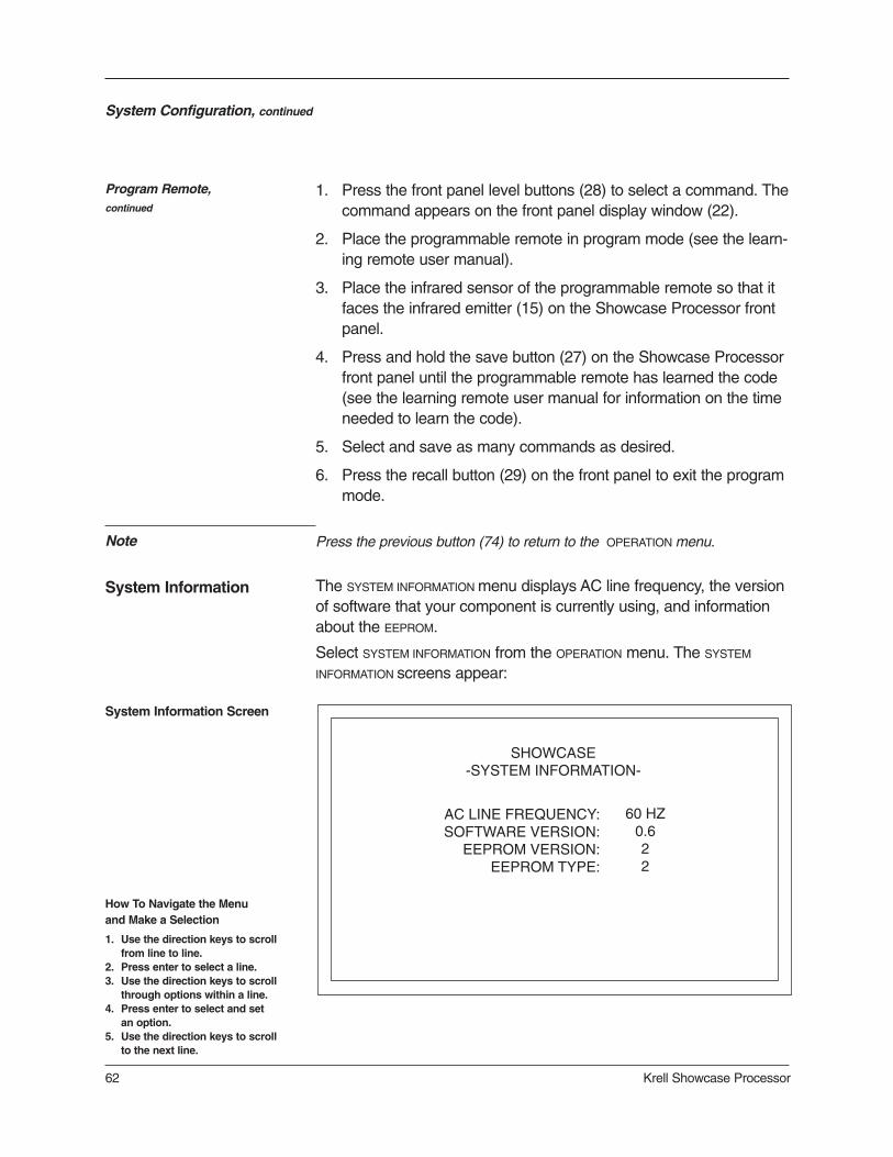
62 Krell Showcase Processor
System Configuration, continued
Program Remote,continued
1. Press the front panel level buttons (28) to select a command. Thecommand appears on the front panel display window (22).
2. Place the programmable remote in program mode (see the learn-ing remote user manual).
3. Place the infrared sensor of the programmable remote so that itfaces the infrared emitter (15) on the Showcase Processor frontpanel.
4. Press and hold the save button (27) on the Showcase Processorfront panel until the programmable remote has learned the code(see the learning remote user manual for information on the timeneeded to learn the code).
5. Select and save as many commands as desired.
6. Press the recall button (29) on the front panel to exit the programmode.
System Information Screen
System Information
SHOWCASE-SYSTEM INFORMATION-
AC LINE FREQUENCY:SOFTWARE VERSION:
EEPROM VERSION:EEPROM TYPE:
60 HZ0.622
The SYSTEM INFORMATION menu displays AC line frequency, the versionof software that your component is currently using, and informationabout the EEPROM.
Select SYSTEM INFORMATION from the OPERATION menu. The SYSTEM
INFORMATION screens appear:
Press the previous button (74) to return to the OPERATION menu.
How To Navigate the Menu and Make a Selection
1. Use the direction keys to scrollfrom line to line.
2. Press enter to select a line.3. Use the direction keys to scroll
through options within a line. 4. Press enter to select and set
an option.5. Use the direction keys to scroll
to the next line.
Note

Please readbefore configuringRoom EQ Setup
System Configuration, continued
ADJUSTABLE PARAMETERS
The Room EQ Setup accesses the Digital Room Equalizer, a featuredesigned by Krell to provide every adjustment from simple bass andtreble to comprehensive room correction. The Digital Room Equalizerenables you to adjust frequency response through three discretebands (I, II, and III). The four adjustable parameters available are fil-ter type, frequency, shape, and level.
There are four Room EQ setup memories, each of which savesevery parameter set for every filter, for every channel. Each setupmemory can save a configuration, for example, one for stereo music,one for multichannel music, one for movie surround, and one forvideo game software.
You can adjust the filters for Showcase Processor channels globallyor individually. Up to three filters can be configured to act equally onall seven channels of audio. Alternatively, each filter can be config-ured separately for each individual channel.
TYPE
Six filter types are available for each filter: Notch Filter, Peaking Filter,High Shelf Filter, Low Shelf Filter, High Pass Filter (HPF) and LowPass Filter (LPF). Each of the filter types available has a uniqueeffect on frequency response.
The following three parameters for filters may be configured, depend-ing on the filter type selected:
FREQ
The center/cutoff frequency can be specified for all six filter types,from 20 Hz to 16 kHz in 1/3 octave increments.
SHAPE
Shape controls the bandwidth of the filter and is adjustable on theNotch and Peaking filter types, from 0.4 to 9 octaves. Shape is fixedat a 6 dB / octave slope for the High and Low Pass Filters. This para-meter is not available for the High and Low Shelf Filters.
LEVEL
Level is adjustable on the Peaking, High Shelf and Low Shelf filters,from -12 dB to +6 dB. Level is fixed for the Notch Filter at - 90 dB.This parameter is not available for the High and Low Pass Filters.
Krell Showcase Processor 63

CHANNEL SELECTION
System Configuration, continued
SAVING ROOM EQ SETUPMEMORY
ACCESSING ROOM EQSETUP MEMORY
When the channel field is set to ALL, the ROOM EQ SETUP menu displaysthe filter settings which apply to all channels and all of the channelsare filtered in the same manner. When the channel parameter selec-tion is set to only one of the channels (L, C, R, LS, RS, LB, RB, S),the filter settings apply to each of the channels individually.
There are four selectable memories associated with the ROOM EQ
SETUP menu. Values are saved automatically when you enter a selec-tion.
Room EQ settings are stored in the Showcase Processor memory inthe same manner as all of the other software settings, for examplethe selections for loudspeaker setup and device configuration. SeeSaving and Recalling Customized Settings and Restoring theFactory Default System Settings, on page 67, for more informa-tion.
When the Showcase Processor is in the operational mode, accessthe saved EQ configurations by pressing the right (arrow) key on theremote. Use the up and down (arrow) remote keys to scan throughthe four memories and OFF.
Exit the main configuration menu by pressing the menu key (82) on theremote. The Showcase Processor is now in operational mode. Press theright arrow directional key followed by the up and down directional keys (75)to scroll through the four EQ memories and OFF.
64 Krell Showcase Processor
The selection ALL overrides individually configured channels.IMPORTANT
APPLYING YOUR CONFIGURATIONS
Your configurations take effect only when you press enter in the APPLY
field. APPLY allows you to hear the effect of the selections you havemade without leaving the menu, if you have a source device playing.
Note
How To Navigate the Menu and Make a Selection
1. Use the direction keys to scrollfrom line to line.
2. Press enter to select a line.3. Use the direction keys to scroll
through options within a line. 4. Press enter to select and set
an option.5. Use the direction keys to scroll
to the next line.

Krell Showcase Processor 65
System Configuration, continued
Room EQ Setup Screen
Room EQ Setup
SHOWCASE-ROOM EQ SETUP-
MEMORYCHANNEL
�� OFF ��N/A
FILTTYPEFREQSHAPELEVEL
IN/AN/AN/AN/A
IIN/AN/AN/AN/A
IIIN/AN/AN/AN/A
APPLY
The final item on the OPERATION menu, ROOM EQ SETUP, allows you toadjust your loudspeaker to your listening area using the Krell DigitalRoom Equalizer. Select ROOM EQ SETUP from the OPERATION menu. TheROOM EQ SETUP screen appears, with the cursor blinking at OFF:
Use the direction and enter keys on the Showcase Processor remotecontrol to scroll through and select the following step-by-step optionsfor audio operation:
MEMORY
Navigate to one of the four memory locations and enter your selec-tion. When the Memory field is set to OFF (the factory default), all ofthe filters are disabled.
CHANNEL
Navigate to CHANNEL and select ALL to apply your configurations to allchannels at once or select any individual channel to apply your con-figurations to that channel. Enter your selection.
IMPORTANT The selection ALL overrides individually configured channels.

66 Krell Showcase Processor
System Configuration, continued
Room EQ Setupcontinued
Note
TYPE
Navigate to TYPE, and configure one, two, or all of the three bands(I, II, III) for FREQ, SHAPE, and LEVEL.
It is not necessary to configure all three filters, you may configure only oneor two filters.
Not all parameters are adjustable for all filter types.
APPLY
Select APPLY and set the selection, if you want to hear your configura-tion. The Room EQ Setup configurations you have just selected audi-ble if you have a source device playing.
After selecting the appropriate loudspeaker configurationfor your sys-tem, press the previous key (74) twice to return to the main configu-ration menu.
Exit the main configuration menu by pressing the menu key (82) onthe remote. The Showcase Processor is now in the operationalmode.
How To Navigate the Menu and Make a Selection
1. Use the direction keys to scrollfrom line to line.
2. Press enter to select a line.3. Use the direction keys to scroll
through options within a line. 4. Press enter to select and set
an option.5. Use the direction keys to scroll
to the next line.

Saving and Recalling Customized Settings andRestoring the Factory Default System Settings
Krell Showcase Processor 67
To save the customized settings that you have entered, press andhold the save button (27) for approximately four seconds. The frontpanel displays SAVING SETUP while the settings are being stored in thenonvolatile memory of the Showcase Processor.
To retrieve your system’s saved settings, press and hold the recallbutton (29) for approximately four seconds. The front panel displaysRECALL SETUP while the settings are being retrieved from the non-volatile memory of the Showcase Processor. Any settings that havebeen saved will be available through recalling system setup.
To replace all system settings with the factory default settings, followthese steps:
1. Press the front panel power button (1) to put your system into theoperational mode.
2. Simultaneously press the recall button (29) and the power button (1).The front panel displays:
PLEASE WAIT
INITIALIZING
Your customized settings for the Showcase Processor revert to thefactory default settings.
If you save your settings, they are still in memory after you restore the factorydefault system settings. Follow Recalling Customized Settings above toretrieve your customized settings.
SAVING CUSTOMIZED SETTINGS
RESTORING THE FACTORY DEFAULTSYSTEM SETTINGS
RECALLING CUSTOMIZEDSETTINGS
Note

Operating the Showcase Processor
68 Krell Showcase Processor
After the Showcase Processor is connected to source devices andamplifiers, and the system setup configured, the ShowcaseProcessor is ready for operation.
1. Insert the AC power cord into the IEC connector (52) on theShowcase Processor. Insert the other end into the AC wall recep-tacle.
2. Move the back panel power switch (51) into the up (on) position.
3. The red stand-by LED on the front panel illuminates. The wordsPLEASE WAIT, INITIALIZING appear in the front panel display (22).When the initializing message disappears, the ShowcaseProcessor is ready to be powered on.
The front panel display shows volume, input information, andselected mode. After five seconds of inactivity, the displaybecomes blank.
4. Use either the front panel power button (1) or the remote controlpower pre key (54) to power on the Showcase Processor. Theblue power LED (2) on the front panel illuminates. The ShowcaseProcessor is now in the operational mode.
5. To return to stand-by, press the front panel power button orpower pre key again.
Krell recommends that the back panel power switch remain up (on) at alltimes.
The Showcase Processor has a discrete tape input and output. Thetape output is used to send an input signal from any analog input (S-1 through S-7, B-1, or VCR) to a recording device or processor.You can use the tape feature in three ways:
1. Use the tape input to playback pre-recorded tapes.
2. Use the tape input to compare the output signal of a three-headanalog tape recorder to the output signal of an audio source.Press the tape button (15) or key (64) to switch between the taperecorder output (LED illuminated) and the input source (LED notilluminated).
ON/OFF/STAND-BY
TAPE INPUT AND OUTPUT
Note
Krell Showcase Processor 69
Operating the Showcase Processor, continued
Tape Input and Output, continued
Notes
3. Use the tape output to create a processor loop, when theShowcase Processor is connected to a graphic equalizer or otherancillary equipment. Connect the equipment to the ShowcaseProcessor tape outputs (34) as described in the equipment man-ufacturer’s manual. Press the tape button (15) or key (64) toswitch between the processor output (LED illuminated) and theinput source (LED not illuminated).
The tape output functions only with analog sources.
There is no tape output from the 7.1 multichannel input.
When changing sources, lower the volume to off or mute the output. Thisensures that the next source played does not damage your system with ahigh output transient.
SIMULCAST When you are listening to or viewing different devices that have dif-ferent trigger settings (configured through the setup menus), you canretain a trigger setting using the previous (74) key.
For example, you have configured your Showcase Processor to turnon your TV monitor when trigger 4 is on and your CD player is set forTRIGGER 4 OFF. You want to watch TV and listen to a CD at the sametime. If you press the TV button or key followed by the CD button orkey, the TV monitor will turn off.
To keep the monitor on and turn on the CD player, follow thesesteps:
1. Press the TV button (10) or key (58) to select the device. Beginplaying the device.
2. Press the prev key (74).
3. Press the CD button (11) or key (59). Begin playing the device.

Appendix: Operating Modes for the Showcase Processor
70 Krell Showcase Processor
The Showcase Processor automatically detects the following signalsand automatically engages the appropriate operating mode for thefollowing signals. Available default modes are listed in Table 5, seepage 42:
DOLBY DIGITAL 2.0 OR DOLBY DIGITAL 2.0 + DOLBY PRO LOGIC
Select a Dolby Digital 2.0 or Dolby Digital 2.0 + Dolby Pro Logicdefault mode using the configuration menu. All modes listed underDolby Digital 2.0, including the default mode you have selected, canbe accessed using the M2 button or key.
DOLBY DIGITAL 5.1
Select a Dolby Digital 5.1 default mode using the configuration menu.All modes listed under Dolby Digital 5.1, including the default modeyou have selected, can be accessed using the M2 button or key.
DOLBY DIGITAL EX
Dolby Digital EX creates six full-bandwidth output channels from 5.1-channel sources. This is done using a matrix decoder thatderives three surround channels from the two in the original record-ing. For best results, Dolby Digital EX should be used with moviesoundtracks recorded with Dolby Digital Surround EX. All modes list-ed under Dolby Digital EX, including the default mode you haveselected, can be accessed using the M2 button or key.
DTS 5.1
Select a DTS 5.1 default mode using the configuration menu. Allmodes listed under DTS 5.1, including the default mode you haveselected, can be accessed using the M2 button or key.
DTS-ES DISCRETE 6.1
The Showcase Processor engages DTS-ES Discrete 6.1 decoding.All of the following modes, plus DTS-ES DISCRETE 6.1 can be accessedusing the M2 button or key: DTS-ES DISCRETE 6.1 + THX, DTS-ES MATRIX 6.1,
DTS-ES MATRIX 6.1 + THX, DTS 5.1 MOVIE, DTS 5.1 MOVIE + THX, and DTS 5.1 MUSIC.
DTS-ES MATRIX 6.1
The Showcase Processor engages DTS ES Matrix 6.1 decoding. Allof the following modes plus DTS-ES MATRIX 6.1 can be accessed usingthe M2 button or key: DTS-ES MATRIX 6.1 + THX, DTS 5.1 MOVIE, DTS 5.1 MOVIE
+ THX, and DTS 5.1 MUSIC.
AUTOMATICALLYDETECTED MODES

Appendix: Additional Operating Modes for the Showcase Processor, continued
User selectable modes available on the Showcase Processor are list-ed below:
DOLBY PRO LOGIC II
Dolby Pro Logic II is the next generation in Dolby Surround decoding.The Pro Logic II decoder takes 2 channels in and 5 channels out. Itis designed specifically to decode all existing Dolby Surround pro-grams with improved spatiality and directionality. Pro Logic II is alsodesigned for use with unencoded stereo music recordings. This fea-ture draws the listener into a three-dimensional space rather thanhearing a flat, two-dimensional presentation.
There are 4 modes in which the Pro Logic II decoder can operate:movie mode (DOLBY PLII MOVIE), music mode (DOLBY PLII MUSIC), matrixmode (DOLBY PLII MATRIX), and Pro Logic mode (DOLBY PRO LOGIC):
DOLBY PLII MOVIE
The movie mode is the improved counterpart to the original Pro Logicdecoder. It is the choice for the majority of Dolby Surround encodedmaterial.
DOLBY PLII MUSIC
The music mode is for use with unencoded stereo music recordings.The music mode features dimension and center width controls, seePLII Control, on page 53, to enhance the music surround experi-ence.
DOLBY PLII MATRIxThe matrix mode is useful for monaural recordings.
DOLBY PRO LOGIC
The Dolby Pro Logic mode provides the same surround processingas the original Pro Logic and is best used with source content that isnot of optimum quality.
USER SELECTABLEMODES
Dolby Pro Logic IIModes
THX SURROUND EX
The Showcase Processor engages THX Surround EX decoding. Thefollowing modes, plus THX SURROUND EX in M1, can be accessed usingthe M2 button or key or the THX button or key: DOLBY D 5.1 and DOLBY
D 5.1 + THX.
Note The DOLBY DIGITAL EX, DOLBY D 5.1 + THX SURR EX, DTS-ES DISCRETE 6.1, and-DTS-EX MATRIX 6.1 operating modes are available only when your system has6 or 7 channels.
Automatically DetectedModes, continued
Krell Showcase Processor 71

Appendix: Additional Operating Modes for the Showcase Processor, continued
72 Krell Showcase Processor
THX
THX post processing can be added to Dolby Surround, Dolby Digital,and DTS encoded material, and includes the following algorithms:
— Re-Equalization takes the edginess or brightness out of yourhome cinema sound.
— Timbre Matching matches the tone of your front loudspeakers toyour surround loudspeakers.
— Adaptive Decorrelation gives a stereo feel when your surroundsource is mono. Adaptive Decorrelation automatically switches offwhen the surround source is stereo.
— Bass Management Electronic Crossover allows you to use morecompact, easier-to-place loudspeakers, while sending bass to asubwoofer system, improving frequency response, lowering dis-tortion and increasing dynamic range.
— Bass Peak Level Manager protects the subwoofer from overload-ing due to the great amount of bass a 5.1 soundtrack delivers.
— Loudspeaker Position Time Synchronization lets you easily setup your system for an optimum listening position.
THX SURR EX
THX Surround EX is a process that decodes a back surround signalfrom the left and right surround channels on specially encoded DolbyDigital DVD movie releases. THX Surround EX uses all the process-ing included in the THX operating mode (see above). Your systemmust include one or two back/surround loudspeakers for THXSurround EX to operate.
If the DVD has the proper encoding, the Showcase Processor will recognizeTHX Surround EX and automatically engage the signal. Many DVD discsinclude THX Surround EX information but do not encode it in a way that asurround processor can recognize.
DTS Neo:6 provides up to six full-bandwidth channels of informationfrom stereo encoded material. 7.1 and 6.1 systems will derive sixchannels from the signal while 5.1 systems will derive five channelsfrom the signal. DTS Neo:6 includes two modes: DTS NEO:6 CINEMA fortwo channel matrixed movie material and DTS NEO:6 MUSIC for stereoencoded music material.
THX and THX Surround EXModes
DTS Neo:6 Modes
Note

Appendix: Additional Operating Modes for the Showcase Processor, continued
Krell Showcase Processor 73
The Krell Music Surround Modes simulate different soundfield experi-ences when listening to music. The table below lists the modes andthe speakers that operate within each mode:
Krell Music SurroundModes
Operating Modes
ActiveLoudspeakers
GENERAL ADMISSION
FRONT ROW
ON STAGE
ENHANCED STEREO
ORCHESTRA
MEZZANINE
FULL RANGE + SUB
MONOPHONIC
PARTY
L/R/S/RRL/R/S/RRL/R/C/S/RRL/R/C/SL/R/C/S/RRL/R/C/S/RRL/R/C/S/RRC/SL/R/C/S/RR
Table 6 Krell Music Surround Modes for theShowcase Processor

Warranty
74 Krell Showcase Processor
This Krell product has a limited warranty of five years for parts and labor on circuitry. Shouldthis product fail to perform at any time during the warranty, Krell will repair it at no cost to theowner, except as set forth in this warranty.
The warranty does not apply to damage caused by acts of God or nature.
The warranty on this page shall be in lieu of any other warranty, expressed or implied, includ-ing, but not limited to, any implied warranty of merchantability or fitness for a particular pur-pose. There are no warranties which exceed beyond those described in this document. If thisproduct does not perform as warranted herein, the owner’s sole remedy shall be repair. In noevent will Krell be liable for incidental or consequential damages arising from purchase, use,or inability to use this product, even if Krell has been advised of the possibility of such dam-ages.
Proof of purchase in the form of a bill of sale or receipted invoice substantiating that the unit iswithin the warranty period must be presented to obtain warranty service. The warranty beginson the date of the original retail purchase, as noted on the bill of sale or receipted invoice froman authorized Krell dealer or distributor. Previously owned equipment, when re-purchased froman authorized Krell dealer or distributor, has the balance of the original warranty, based on theoriginal date of manufacture.
The warranty for Krell products is valid only in the country to which they were originally shipped,through the authorized Krell distributor for that country, and at the factory. There may be restric-tions on or changes to Krell’s warranty because of regulations within a specific country. Pleasecheck with your distributor for a complete understanding of the warranty in your country.
If a unit is serviced by a distributor who did not import the unit, there may be a charge for ser-vice, even if the product is within the warranty period.
Freight to the factory is your responsibility. Return freight within the United States (U.S.A.) isincluded in the warranty. If you purchased your Krell product outside the U.S.A. and wish tohave it serviced at the factory, all freight and associated charges to the factory are your respon-sibility. Krell will pay return freight to the U.S.A.-based freight forwarder of your choice. Freightand other charges to ship the unit from the freight forwarder to you are also your responsibility.
Krell is not responsible for any damage incurred in transit. Krell will file claims for damages asnecessary for units damaged in transit to the factory. You are responsible for filing claims forshipping damages during the return shipment.
Krell does not supply replacement parts and/or products to the owner of the unit. Replacementparts and/or products will be furnished only to the distributor performing service on this unit onan exchange basis only; any parts and/or products returned to Krell for exchange become theproperty of Krell.
No expressed or implied warranty is made for any Krell product damaged by accident, abuse,misuse, natural or personal disaster, or unauthorized modification.
Any unauthorized voltage conversion, disassembly, component replacement, perfora-tion of chassis, updates, or modifications performed to the unit will void the warranty.
The operating voltage of this unit is determined by the factory and can only be changed by anauthorized Krell distributor or at the factory. The voltage for this product in the U.S.A. cannot bechanged until six months from the original purchase date.
In the event that Krell receives a product for warranty service that has been modified in anyway without Krell authorization, all warranties on that product will be void. The product will bereturned to original factory layout specifications at the owner’s expense before it is repaired. Allrepairs required after the product has been returned to original factory specifications will becharged to the customer, at current parts and labor rates.
All operational features, functions, and specifications and policies are subject to change withoutnotification.
To register your product for
warranty benefits, please
complete and return the
Warranty Registration Card
enclosed in the shipping box
within 15 days of purchase.
Thank you.

Return Authorization Procedure
Krell Showcase Processor 75
If you believe there is a problem with your component, please con-tact your dealer, distributor, or the Krell factory to discuss the problembefore you return the component for repair. To expedite service, youmay wish to complete and e-mail the Service Request Form in theService section of our website at:
http://www.krellonline.com
To return a product to Krell, please follow this procedure so that wemay serve you better:
1. Obtain a Return Authorization Number (R/A number) and ship-ping address from the Krell Service Department.
2. Insure and accept all liability for loss or damage to the productduring shipment to the Krell factory and ensure all freight (ship-ping) charges are prepaid.
The product may also be hand delivered if arrangements with theService Department have been made in advance. Proof of purchasewill be required for warranty validation at the time of hand delivery.
Use the original packaging to ensure the safe transit of the product tothe factory, dealer, or distributor. Krell may, at its discretion, return aproduct in new packaging and bill the owner for such packaging if theproduct received by Krell was boxed in nonstandard packaging or ifthe original packaging was so damaged that it was unuseable. If Krelldetermines that new packaging is required, the owner will be notifiedbefore the product is returned.
HOW TO RETURNA PRODUCT
IMPORTANT
To purchase additional packaging, please contact your authorizedKrell dealer, distributor, or the Krell Service Department for assis-tance.
HOW TO PURCHASEADDITIONAL PACKING
To contact the Krell Service Department:
TEL 203-799-9954Monday-Friday, 9:00 AM to 5:00 PM EST
FAX 203-799-9796E-MAIL [email protected] SITE http://www.krellonline.com
Your Showcase Processor product serial number is:SERIAL NUMBER
HOW TO EXPEDITESERVICE

Specifications
76 Krell Showcase Processor
OUTPUTS
REMOTE
DECODING MODES
INPUTS
SIGNAL-TO-NOISE RATIO
TOTAL HARMONICDISTORTION (THD)
"A" WEIGHTED 94 dB
UNWEIGHTED 20 Hz-20 kHz, -88 dB
ANALOG AUDIO 1 pair balanced via XLR connectors7 pairs single-ended via RCA connectorsone 7.1 via RCA connectors
DIGITAL AUDIO 4 coaxial via RCA connectors4 EIAJ optical via TosLink connectors
VIDEO 4 S-video via DIN connectors4 composite via RCA connectors3 component via RCA connector
ANALOG TAPE 2 pair single-ended via RCA connectors
ANALOG CHANNEL 8 balanced via XLR connectors (one per channel) 8 single-ended via RCA connectors
ANALOG TAPE 1 pair single-ended via RCA connectors
DIGITAL 1 coaxial via RCA connector1 EIAJ optical via TosLink connectors
VIDEO 2 S-video via DIN connector, 1 with OSD2 composite via RCA connectors,
1 with OSD1 component via RCA connectors with OSD
REMOTE CONTROL 1 infrared
REMOTE CONNECTORS 1 RS-2321 RC-5 input4 12 VDC OUT (12 V trigger)1 12 VDC IN (12 V trigger)
Dolby Pro Logic IIDolby Digital 5.1Dolby Digital EXDTS 5.1DTS ES Discrete 6.1DTS ES Matrix 6.1THX Surround EXDTS Neo:6

Specifications, continued
Krell Showcase Processor 77
WEIGHT
SURROUND ENHANCEMENTMODES
DIMENSIONS
KRELL MUSIC SURROUND General AdmissionFront RowOn StageEnhanced StereoOrchestraMezzanineFull Range + SubMonophonicParty
35 W
INCHES 17.25w x 5.65h x 16.45d
CENTIMETERS 43.82w x 14.35h x 41.78d
SHIPPING 25 lb. 11.3 kg
UNIT ONLY 19.25 lb. 8.75 kg
All operational features, functions, specifications, and policies are subject tochange without notification.
POWER CONSUMPTION

Krell Industries, Inc.45 Connair RoadOrange, CT 06477-3650 USA
TEL 203-799-9954FAX 203-891-2028E-MAIL [email protected] http://www.krellonline.com
Showcase ProcessorSurround
Preamp/Processor
v 02.3