instructions for use babylog 8000 plus - draeger
TRANSCRIPT

Instructions for use
Babylog 8000 plus
WARNING
To properly use this medical device, read and comply with these instructions for use.
Intensive care ventilator for neonatesSoftware 5.n

2 Instructions for use Babylog 8000 plus SW 5.n
Typographical conventions
Any text shown on the screen and any labeling on the device are printed in bold and italics, for example, FiO2, IPPV or Vent. Mode. Translations of these texts are printed in bold and italics and are placed in parentheses. These translations in parentheses are not displayed on the device.
The "greater than" symbol > indicates the navigation path in a dialog window, for example, Options > VIVE. In this example, Options represents the dialog window title and VIVE a screen in the dialog window.
Use of terms
Dräger uses the term "accessories" not only for accessories in the sense of IEC 60601-1, but also for consumables, removable parts, and attached parts.
Product name used
In these instructions for use, the designation Babylog 8000 is used for "Babylog 8000 plus".
Screen reproductions
The reproductions of screen content in the instructions for use can differ from the content actually shown on the screen.
Trademarks
1 Consecutive numbers indicate steps of action, with the numbering restarting with "1" for each new sequence of actions.
Bullet points indicate individual actions or dif-ferent options for action.
– Dashes indicate the listing of data, options, or objects.
(A) Letters in parentheses refer to elements in the related illustration.
A Letters in illustrations denote elements referred to in the text.
Trademark Trademark owner
Babylog®
DrägerBabyLink®
DrägerService®
MEDIBUS®
Buraton® Schülke & Mayr GmbH

Instructions for use Babylog 8000 plus SW 5.n 3
Safety information definitions
Definition of target groups
For this product, users, service personnel, and experts are defined as target groups.
These target groups must have received instruction in the use of the product and must have the necessary training and knowledge to use, install, reprocess, maintain, or repair the product. The target groups must understand the language of the present document.
The product must be used, installed, reprocessed, maintained, or repaired exclusively by defined target groups.
Users
Users are persons who use the product in accordance with its intended use.
Service personnel
Service personnel are persons who are responsible for the maintenance of the product.
Service personnel must be trained in the maintenance of medical devices and install, reprocess, and maintain the product.
Experts
Experts are persons who perform repair or complex maintenance work on the product.
Experts must have the necessary knowledge and experience with complex maintenance work on the product.
WARNING
A WARNING statement provides important information about a potentially hazardous situation which, if not avoided, could result in death or serious injury.
CAUTION
A CAUTION statement provides important information about a potentially hazardous situation which, if not avoided, may result in minor or moderate injury to the user or patient or in damage to the medical device or other property.
NOTE
A NOTE provides additional information intended to avoid inconvenience during operation.

4 Instructions for use Babylog 8000 plus SW 5.n
Abbreviations and symbols
Explanations can be found in the sections ''Abbreviations'' and ''Symbols'' in chapter ''Overview''.
Instructions for use Babylog 8000 plus SW 5.n 5
Contents
Contents
For your safety and that of your patients.... 7
General safety information .............................. 8Product-specific safety information.................. 12
Application ..................................................... 15
Intended use.................................................... 16Environment of use.......................................... 16
Overview......................................................... 17
Babylog 8000................................................... 18Trolley.............................................................. 22Range of functions........................................... 23Abbreviations................................................... 24Symbols........................................................... 26Product labels.................................................. 27
Operating concept......................................... 28
Control and display unit ................................... 29Dialog windows................................................ 33
Assembly and preparation ........................... 37
Safety information............................................ 38Preparing the trolley ........................................ 38Mounting an additional monitor ....................... 40Preparing the ventilator ................................... 42Connecting a gas analyzer .............................. 48Establishing the gas supply ............................. 49Establishing the power supply ......................... 50MEDIBUS protocol .......................................... 51Establishing potential equalization .................. 52Transport within the hospital............................ 53
Getting started ............................................... 54
Safety information............................................ 55Switching on the ventilator............................... 55Charging the battery for the power supply failure alarm..................................................... 57Checking readiness for operation.................... 58
Operation........................................................ 62
Setting ventilation ............................................ 63Endotracheal suction....................................... 68Manual inspiration ........................................... 69Medication nebulization ................................... 70Analog and digital interface ............................. 76
Terminating operation ..................................... 80
Alarms ............................................................ 81
Display of alarms............................................. 82Suppressing the acoustic alarm signal............ 83Acknowledging alarm messages..................... 83Alarm limits...................................................... 84
Trends ............................................................ 86
Displaying waveforms and measured values .. 87Displaying trends............................................. 90Displaying the logbook .................................... 91
Monitoring ...................................................... 92
Information on monitoring................................ 93O2 monitoring .................................................. 94Flow monitoring ............................................... 95
Configuration ................................................. 98
Displaying device information.......................... 99Setting date and time ...................................... 99Setting the volume of the alarm signal ............ 100Setting the screen contrast.............................. 100Selecting the language.................................... 101Configuring the data interfaces ....................... 101
Troubleshooting ............................................ 105
Failure of the power supply ............................. 106Alarm – Cause – Remedy ............................... 106
Cleaning, disinfection and sterilization....... 110
Safety information ........................................... 111Dismantling the ventilator ................................ 111Reprocessing methods.................................... 114Reprocessing list ............................................. 117After reprocessing ........................................... 119
Maintenance................................................... 120
Overview ......................................................... 121Inspection ........................................................ 122Preventive maintenance.................................. 124Repairs ............................................................ 125Replacing the cooling air filter ......................... 126
Contents
6 Instructions for use Babylog 8000 plus SW 5.n
Disposal ......................................................... 127
Disposal of the medical device........................ 128Disposal of batteries........................................ 128Disposal of O2 sensors.................................... 129
Technical data ............................................... 130
Ambient conditions .......................................... 131Set values........................................................ 131Performance characteristics............................ 133Displayed measured values ............................ 134Displayed calculated measured values ........... 137Monitoring functions ........................................ 138Operating characteristics................................. 139Device outputs................................................. 141Essential performance characteristics............. 142Alarm criteria ................................................... 143EMC Declaration ............................................. 146Connection to IT networks............................... 151
Principles of operation ................................. 152
Pneumatic function description ....................... 153Description of ventilation modes ..................... 156Additional settings for ventilation..................... 161Measurements................................................. 165
Instructions for use Babylog 8000 plus SW 5.n 7
For your safety and that of your patients
For your safety and that of your patients
General safety information ........................... 8
Strictly follow these instructions for use........... 8Maintenance.................................................... 8Safety checks .................................................. 8Accessories ..................................................... 8Not for use in areas of explosion hazard......... 9Connected devices.......................................... 9Device combinations ....................................... 9Patient safety................................................... 10Patient monitoring............................................ 10Information on electromagnetic compatibility .. 10Disposable product.......................................... 11Sterile accessories .......................................... 11Installing accessories ...................................... 11Storing the instructions for use........................ 11Training............................................................ 11
Product-specific safety information ............ 12
Ensuring ventilation using an independent manual ventilator ............................................. 14
For your safety and that of your patients
8 Instructions for use Babylog 8000 plus SW 5.n
General safety information
The following WARNING and CAUTION statements apply to general operation of the medical device.WARNING and CAUTION statements specific to subsystems or particular features of the medical device appear in the respective sections of these instructions for use or in the instructions for use of another product being used with this device.
Strictly follow these instructions for use
Maintenance
Safety checks
The medical device must be subject to regular safety checks. See chapter ''Maintenance''.
Accessories
WARNING
Risk of incorrect operation and incorrect use
Any use of the medical device requires full understanding and strict observation of all sections of these instructions for use. The medical device must only be used for the purpose specified under ''Intended use'' (see page 16) and in conjunction with appropriate patient monitoring (see page 10). Strictly observe all WARNING and CAUTION statements throughout these instructions for use and all statements on medical device labels.
Failure to observe these safety information statements constitutes a use of the medical device that is inconsistent with its intended use.
WARNING
Risk of medical device failure and of patient injury
The medical device must be inspected and serviced regularly by service personnel. Repair and complex maintenance carried out on the medical device must be performed by experts. Dräger recommends DrägerService for a service contract and for repairs. Dräger also recommends using original Dräger parts for maintenance.
If the above is not complied with, medical device failure and patient injury may occur. Observe chapter ''Maintenance''.
WARNING
Risk due to incompatible accessories
Dräger has only tested the compatibility of accessories that appear in the current list of accessories or in separate declarations by Dräger. If other, incompatible accessories are used, there is a risk of patient injury due to medical device failure.
Dräger recommends using the medical device only with accessories from the current list of accessories.

Instructions for use Babylog 8000 plus SW 5.n 9
For your safety and that of your patients
Not for use in areas of explosion hazard
Connected devices
Device combinations
This device can be operated in combination with other Dräger devices or with devices from other manufacturers. Observe the accompanying documents of the individual devices.
If a device combination is not approved by Dräger, the safety and the functional state of the individual devices can be compromised. The operating organization must ensure that the device combination complies with the applicable editions of the relevant standards for medical devices.
Device combinations approved by Dräger meet the requirements of the following standards:
– IEC 60601-1, 3rd edition (general requirements for safety, device combinations, software-controlled functions)
– IEC 60601-1-2 (electromagnetic compatibility)
– IEC 60601-1-8 (alarm systems)
Or:
– IEC 60601-1, 2nd edition (general requirements for safety)
– IEC 60601-1-1 (device combinations)
– IEC 60601-1-2 (electromagnetic compatibility)
– IEC 60601-1-4 (software-controlled functions)
– IEC 60601-1-8 (alarm systems)
WARNING
Risk of fire
The device is not approved for use in areas where combustible or explosive gas mixtures are likely to occur.
WARNING
Risk of electric shock and of device malfunction
Electrical connections to equipment not listed in these instructions for use or these assembly instructions must only be made when approved by each respective manufacturer.
Before operating the medical device, strictly comply with the instructions for use of all connected devices or device combinations.

For your safety and that of your patients
10 Instructions for use Babylog 8000 plus SW 5.n
Patient safety
The design of the medical device, the accompanying documentation, and the labeling on the medical device are based on the assumption that the purchase and the use of the medical device are restricted to persons familiar with the most important inherent characteristics of the medical device.
Instructions and WARNING and CAUTION statements are therefore largely limited to the specifics of the Dräger medical device.
The instructions for use do not contain any information on the following points:
– Risks that are obvious to users
– Consequences of obvious improper use of the medical device
– Potentially negative effects on patients with different underlying diseases
Medical device modification or misuse can be dangerous.
Patient monitoring
The user of the medical device is responsible for choosing suitable monitoring that provides appropriate information about medical device performance and the patient's condition.
Patient safety may be achieved by a wide variety of means ranging from electronic surveillance of medical device performance and patient condition to simple, direct observation of clinical signs.
The responsibility for selecting the best level of patient monitoring lies solely with the user of the medical device.
Information on electromagnetic compatibility
General information on electromagnetic compatibility (EMC) according to international EMC standard IEC 60601-1-2:
Medical electrical equipment is subject to special precautionary measures concerning electromagnetic compatibility (EMC) and must be installed and put into operation in accordance with the EMC information provided (see ''EMC Declaration'').
Portable and mobile radio frequency communication equipment can affect medical electrical equipment.
WARNING
Risk of electric shock
Do not connect connectors with an ESD warning symbol and do not touch their pins without implementing ESD protective measures. Such protective measures can include antistatic clothing and shoes, touching a potential equilization pin before and during connection of the pins, or using electrically insulating and antistatic gloves.
All users concerned must be instructed in these ESD protective measures.
WARNING
Risk of device failure
Electromagnetic fields can compromise proper operation of the device. Electromagnetic fields are generated by, e.g.,:– Mobile phones– Radio frequency electrosurgical equipment– Defibrillators– Shortwave therapy equipment
Maintain sufficient safety distances, see EMC declaration in chapter ''Technical data''.

Instructions for use Babylog 8000 plus SW 5.n 11
For your safety and that of your patients
Disposable product
Sterile accessories
Installing accessories
Strictly observe the instructions for use and assembly instructions.
Storing the instructions for use
Training
User training is offered by the responsible Dräger organization, see www.draeger.com.
WARNING
Risk of patient injury due to failure of accessories
Disposable products have been developed, tested, and manufactured for disposable use only. Reuse, reprocessing or sterilization can lead to a failure of the accessories and cause injuries to the patient.
Do not reuse, reprocess, or sterilize disposable products.
CAUTION
Risk of medical device failure and of patient injury
Do not use sterile-packaged accessories if the packaging has been opened, is damaged, or if there are other signs of non-sterility.
CAUTION
Risk of device failure
Install the accessory on the basic device in accordance with the instructions of the basic device.
Check for secure connection to the basic device.
CAUTION
Risk of incorrect use
Instructions for use must be kept accessible to the user.

For your safety and that of your patients
12 Instructions for use Babylog 8000 plus SW 5.n
Product-specific safety information
WARNING
Risk of incorrect use
This medical device is intended to be used only by the target group "users".
WARNING
Risk of suffocation following device failure
If the gas inlet for the emergency breathing valve is obstructed, the patient will not be able to breathe spontaneously in the case of a device failure.
Do not obstruct the gas inlet for the emergency breathing valve.
WARNING
Risk of malfunction
Unallowed modifications to the medical device lead to malfunctions.
This medical device must not be altered without permission from Dräger.
WARNING
Risk of patient injury
During magnetic resonance imaging the correct functioning of the medical device can be impaired.
Do not use the medical device during magnetic resonance imaging.
WARNING
Risk of patient injury
In hyperbaric chambers the correct functioning of the medical device can be impaired.
Do not use the medical device in hyperbaric chambers.
WARNING
Risk of patient injury with PEEP <2.5 mbar (2.5 cmH2O)
If the PEEP is set to <2.5 mbar (2.5 cmH2O) and the following settings are also made, the integrated pressure monitoring cannot detect an alarm situation during disconnection or extubation and their immediate consequences:– Pinsp <10 mbar (10 cmH2O)– Ventilation mode with volume guarantee– Change from a ventilation mode with VG into the ventilation mode IPPV, without switching off VGFrom a PEEP of 2.5 mbar (2.5 cmH2O) the risk of an undetected alarm situation increases with decreasing PEEP values.
Use external ventilation monitoring as well as the following types of monitoring with narrow alarm limits:– SpO2 monitoring– Bradycardia monitoring– TcO2/TcCO2 monitoring
WARNING
Risk of eye injury
With neonates, the administration of increased O2 concentrations can lead to retinopathy of prematurity.
Use additional monitoring, e.g., external SpO2 monitoring.
WARNING
Risk of incorrect NO dosing
If a device for nitric oxide (NO) delivery without internal NO monitoring is used, patient monitoring is not guaranteed.
Monitor the NO concentration separately.

Instructions for use Babylog 8000 plus SW 5.n 13
For your safety and that of your patients
WARNING
Risk of fire
The flow sensor can ignite medications or other substances based on highly flammable substances.– Do not nebulize medications or other
substances that are easily flammable or spray them into the device.
– Do not use substances containing alcohol.– Do not allow flammable or explosive
substances to enter the breathing system or the breathing circuit.
WARNING
Risk due to failure of flow measurement
Deposits that were not removed during reprocessing can damage the measuring wires in the flow sensor or cause a fire.– Before inserting the flow sensor check for
visible damage, soiling, and particles. Repeat this check regularly.
– Replace flow sensors when damaged, soiled, or not particle-free.
WARNING
Risk of fire
The use of unapproved O2 pressure reducers can lead to excess pressure, which can cause a fire.– When supplying the ventilator with
oxygen from a compressed gas cylinder, only use pressure reducers compliant with ISO 10524.
– Slowly open the pressure reducer manually. Do not use tools.
WARNING
Risk of fire
The medical device may catch fire as a result of oxygen enrichment in the ambient air. Medical device malfunctions can increase the O2 concentration in the ambient air.
The medical device is only suitable for use in rooms with sufficient ventilation.
WARNING
Risk of fire
Do no use the medical device together with flammable gases or flammable solutions that may become mixed with air, oxygen or nitrous oxide, or other ignition sources, as the medical device may catch fire.
Do not allow the medical device to come into contact with sources of ignition.
WARNING
Risk of electric shock
There is a risk of electric shock if the connectors of the interfaces and the patient are touched simultaneously.
Do not simultaneously touch the connectors of the interfaces and the patient.
WARNING
Risk of patient injury
Penetrating liquid may cause malfunction of the device, which may endanger the patient.– Do not place any containers with liquid on
or above the device.– Make sure that no liquid penetrates into
the device when disinfecting surfaces.
For your safety and that of your patients
14 Instructions for use Babylog 8000 plus SW 5.n
Ensuring ventilation using an independent manual ventilator
CAUTION
Risk of patient injury
Do not make therapeutic decisions based solely on individual measured values and monitoring parameters.
CAUTION
Risk of patient injury
Positive-pressure ventilation can lead to negative effects, such as barotrauma or strain on the circulatory system.
Monitor the patient's condition.
CAUTION
Reduced O2 concentration
When nitric oxide (NO) is added, the set inspiratory O2 concentration may be reduced.
Monitor the O2 concentration.
CAUTION
Risk of medical device overheating
The medical device may overheat due to sources of heat such as direct sunlight, heat radiators, or spotlights.– Keep the medical device away from sources
of heat.– Only operate the medical device in rooms
with sufficient ventilation.– Do not cover the medical device or slide the
rear of the device against a wall.
CAUTION
Risk of medical device overheating
If the ventilation slots on the medical device are covered or sealed, the medical device may overheat.– Air must be able to enter freely.– An alarm is triggered if the medical device
overheats during operation.
CAUTION
Risk of personal injury
If the glass on the LC screen is damaged, a chemical liquid may escape.– Avoid contact with the body.– Immediately clean affected skin areas with
soap.
WARNING
Risk of patient injury
If a fault is detected in the medical device, its life-support functions may no longer be assured.
Ventilation of the patient using an independent ventilation device must be started without delay, if necessary with PEEP and/or an increased inspiratory O2 concentration (e.g., with a manual resuscitator).
Instructions for use Babylog 8000 plus SW 5.n 15
Application
Application
Intended use .................................................. 16
Environment of use ....................................... 16

Application
16 Instructions for use Babylog 8000 plus SW 5.n
Intended use
Babylog 8000 plus 5.n is a long-term ventilator for premature babies, newborns, and children with a body weight of up to approx. 20 kg (44 lbs).
The device must only be operated by doctors or, on a doctor's order, by clinical personnel.
Each user must be trained and familiar with the instructions for use.
Environment of use
Babylog 8000 is intended for use in intensive care units.
Do not use Babylog 8000 in the following environments:
– In hyperbaric chambers
– For magnetic resonance imaging (MRI, NMR, NMI)
– In conjunction with flammable gases or flammable solutions that can mix with air, oxygen, or nitrous oxide
– In areas of explosion hazard
– In areas with combustible or explosive substances
– In rooms without sufficient ventilation
Instructions for use Babylog 8000 plus SW 5.n 17
Overview
Overview
Babylog 8000 ................................................. 18
Ventilator on trolley.......................................... 18Control and display unit ................................... 19Patient connection panel ................................. 20Rear................................................................. 21
Trolley............................................................. 22
Range of functions ........................................ 23
Ventilation functions ........................................ 23Monitoring functions ........................................ 23Power supply ................................................... 23Gas supply....................................................... 23Data transfer (optional).................................... 23Medication nebulization ................................... 23Non-invasive ventilation................................... 23
Abbreviations................................................. 24
Symbols.......................................................... 26
Product labels................................................ 27
Overview
18 Instructions for use Babylog 8000 plus SW 5.n
Babylog 8000
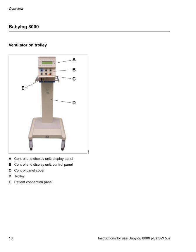
Ventilator on trolley
A Control and display unit, display panel
B Control and display unit, control panel
C Control panel cover
D Trolley
E Patient connection panel
21
98
8
A
B
C
D
E
Instructions for use Babylog 8000 plus SW 5.n 19
Overview
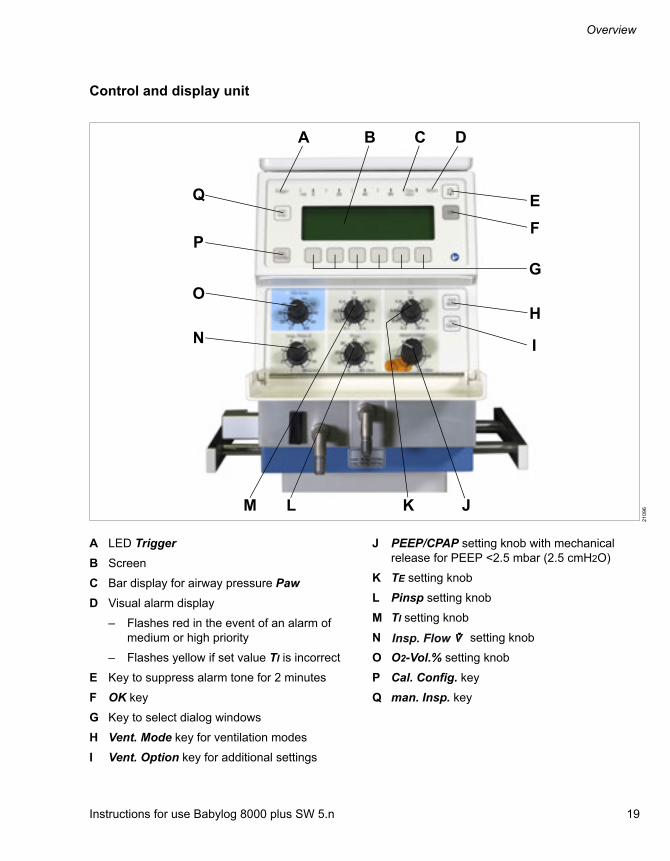
Control and display unit
21
09
6
Q
N
M L
H
I
K J
A B C D
E
F
O
P
G
A LED Trigger
B Screen
C Bar display for airway pressure Paw
D Visual alarm display
– Flashes red in the event of an alarm of medium or high priority
– Flashes yellow if set value TI is incorrect
E Key to suppress alarm tone for 2 minutes
F OK key
G Key to select dialog windows
H Vent. Mode key for ventilation modes
I Vent. Option key for additional settings
J PEEP/CPAP setting knob with mechanical release for PEEP <2.5 mbar (2.5 cmH2O)
K TE setting knob
L Pinsp setting knob
M TI setting knob
N setting knob
O O2-Vol.% setting knob
P Cal. Config. key
Q man. Insp. key
Insp. Flow

Overview
20 Instructions for use Babylog 8000 plus SW 5.n
Patient connection panel
A "Exhaust" muffler
B Rocker lever for expiratory valve
C Expiratory port "GAS RETURN"
D Inspiratory port "GAS OUTPUT"
211
00
A B C D
Instructions for use Babylog 8000 plus SW 5.n 21
Overview
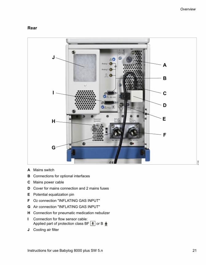
Rear
A Mains switch
B Connections for optional interfaces
C Mains power cable
D Cover for mains connection and 2 mains fuses
E Potential equalization pin
F O2 connection "INFLATING GAS INPUT"
G Air connection "INFLATING GAS INPUT"
H Connection for pneumatic medication nebulizer
I Connection for flow sensor cable:Applied part of protection class BF or B
J Cooling air filter
211
08
J
I C
A
B
E
F
G
D
H

Overview
22 Instructions for use Babylog 8000 plus SW 5.n
Trolley
A Babylog 8000
B Device holder
C Trolley column
D Hose holder
E Castor with locking brake, 2 pieces
F Castor with locking brake, 2 pieces
G Base plate
H Holder
I Lateral standard rail
21
60
8
A
B
C
D
E
H
G
F
I

Instructions for use Babylog 8000 plus SW 5.n 23
Overview
Range of functions
The functions described correspond to the overall functionality of Babylog 8000. Some functions are only optional and may not be included in the individual device configuration. The optional functions and order numbers for accessories are listed in the separate list of accessories.
Ventilation functions
For a detailed description of the ventilation modes and the additional settings, see page 152. For a list of abbreviations, see page 24.
Ventilation modes
– IPPV/IMV
– SIPPV
– SIMV
– PSV (optional)
– CPAP
Additional settings for ventilation
– VG (optional)
– HFV (optional)
– VIVE
Monitoring functions
The following parameters are monitored:
– Inspiratory O2 concentration FiO2
– Airway pressure Paw
– Flow, minute volume MV, and tidal volume VT
– Leakage rate Leak
– Respiratory rate for panting breathing Panting
– Apnea alarm time Apnoea time
Babylog 8000 calculates additional lung parameters using the measured values for pressure, flow, and volume.
Power supply
The device is supplied with mains power.
Gas supply
The device features country-specific connections for the gas supply with oxygen and medical compressed air.
Data transfer (optional)
Babylog 8000 can be equipped with the "Communication" kit for transferring measured data and settings to devices such as patient monitors or computers.
The serial RS232 interface can be used for data transfer using the MEDIBUS protocol.
An analog interface is available for analog data output.
Medication nebulization
For medication nebulization a pneumatic medication nebulizer can be connected.
Non-invasive ventilation
Non-invasive ventilation is possible if BabyFlow accessories are used. Additional information can be found in the BabyFlow instructions for use.

Overview
24 Instructions for use Babylog 8000 plus SW 5.n
Abbreviations
Abbreviation Explanation
%, Vol.% Gas proportion as a percentage of the total volume
Air Medical compressed air
BTPS Body Temperature and Pres-sure, Saturated
C Compliance
C20/C Index of the last 20 % of compli-ance in relation to the dynamic total compliance
cmH2O Centimeters of water
CO2 Carbon dioxide
CPAP Continuous Positive Airway Pressure
DCO2 Transport coefficient describing the transport of CO2 from the lungs
EMC Electromagnetic compatibility
ESD Electrostatic Discharge, electro-static discharge
f Respiratory rate
FiO2 Inspiratory oxygen fraction
fset Set respiratory rate
HFV High-Frequency Ventilation
hPa Hectopascal
I:E Ratio of inspiratory time to expi-ratory time
IMV Intermittent Mandatory Ventila-tion
Setting knob for inspiratory flow
IPPV Intermittent Positive-Pressure Ventilation
IRV Inverse-Ratio Ventilation
kg Kilogram
L Liter
Insp. Flow
lbs Pound; unit of mass
LED Light emitting diode
mbar Millibar
Mean Mean pressure
min Minute
mL Milliliter
MRI Magnetic resonance imaging
MV Minute volume
MVim Minute volume applied with man-datory breaths during high-fre-quency ventilation, measured on the inspiratory side
NTPD Normal Temperature, Pressure, Dry
Paw Airway pressure
Peak Peak pressure
PEEP Positive end-expiratory pressure
Pinsp Inspiratory pressure
PSV Pressure-Supported Ventilation
r Correlation coefficient of linear regression
R Resistance
RC Resistance and Compliance
RVR Rate-Volume Ratio
SIPPV Synchronized Intermittent Posi-tive-Pressure Ventilation
Tc Time constant
TE Expiratory time
TI Inspiratory time
TIspo Inspiratory time during sponta-neous breathing
Abbreviation Explanation
Instructions for use Babylog 8000 plus SW 5.n 25
Overview
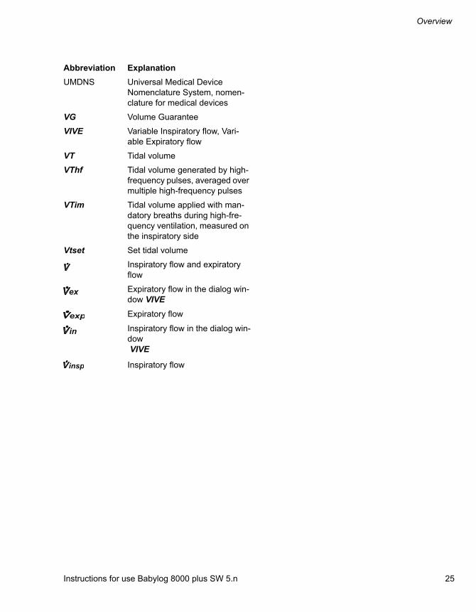
UMDNS Universal Medical Device Nomenclature System, nomen-clature for medical devices
VG Volume Guarantee
VIVE Variable Inspiratory flow, Vari-able Expiratory flow
VT Tidal volume
VThf Tidal volume generated by high-frequency pulses, averaged over multiple high-frequency pulses
VTim Tidal volume applied with man-datory breaths during high-fre-quency ventilation, measured on the inspiratory side
Vtset Set tidal volume
Inspiratory flow and expiratory flow
Expiratory flow in the dialog win-dow VIVE
Expiratory flow
Inspiratory flow in the dialog win-dow VIVE
Inspiratory flow
Abbreviation Explanation
ex
exp
in
insp

Overview
26 Instructions for use Babylog 8000 plus SW 5.n
Symbols
Symbol Explanation
Manufacturer
Date of manufacture
WEEE label, Directive 2002/96/EC
Warning! Strictly follow these instructions for use
Caution! Observe the accompa-nying documentation! (symbol)
Consult instructions for use
Applied part, protection class BF (Body Floating)
Applied part, protection class B (Body)
Connection for potential equal-ization
Marking on surfaces on the device where pushing, leaning, propping, etc., increase the risk of tipping over
Order number
Serial number
Batch designation
Use by
Keep away from sunlight
Protect from moisture
Storage temperature
Relative humidity
XXXX
REF
LOT
Atmospheric pressure
Do not use if package damaged
Lower alarm limit
Upper alarm limit
Reduce time segment
Increase time segment
Back to main screen
Dialog window for the logbook
Dialog window for setting alarm limits for the minute volume
Reduce, scroll back
Increase, scroll forward
Shift time segment, select parameter
Shift time segment, select parameter
Suppress acoustic alarm for 2 minutes.
Pulse signal for display of events during ventilation
Set the volume of the alarm tone
Reduce
Increase
Selecting the parameter
Switch device on, switch device off
Symbol Explanation

Instructions for use Babylog 8000 plus SW 5.n 27
Overview
Product labels
Product label Explanation
Maximum loads and conditions for maintaining the stability of the device on the trolley
Nominal weight and maximum weight (for further information, see chapter ''Technical data'')

Operating concept
28 Instructions for use Babylog 8000 plus SW 5.n
Operating concept
Control and display unit ............................... 29
Layout of the control and display unit .............. 29Setting knobs................................................... 29Keys with fixed and variable functions ............ 30Displays........................................................... 32
Dialog windows ............................................. 33
Dialog window layout....................................... 33Opening dialog windows ................................. 33Main screen..................................................... 33Overview of dialog windows ............................ 34
Instructions for use Babylog 8000 plus SW 5.n 29
Operating concept
Control and display unit
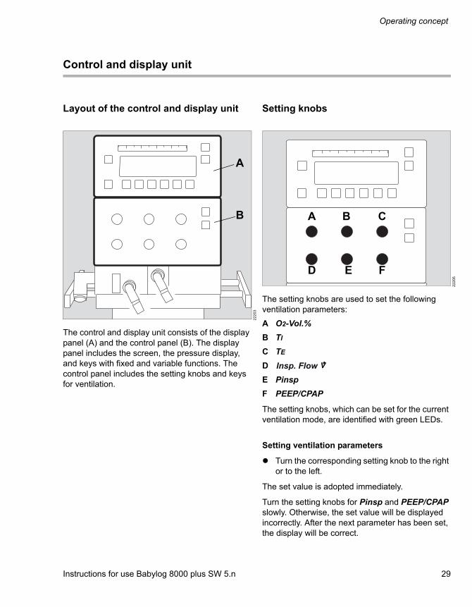
Layout of the control and display unit
The control and display unit consists of the display panel (A) and the control panel (B). The display panel includes the screen, the pressure display, and keys with fixed and variable functions. The control panel includes the setting knobs and keys for ventilation.
Setting knobs
The setting knobs are used to set the following ventilation parameters:
A O2-Vol.%
B TI
C TE
D
E Pinsp
F PEEP/CPAP
The setting knobs, which can be set for the current ventilation mode, are identified with green LEDs.
Setting ventilation parameters
Turn the corresponding setting knob to the right or to the left.
The set value is adopted immediately.
Turn the setting knobs for Pinsp and PEEP/CPAP slowly. Otherwise, the set value will be displayed incorrectly. After the next parameter has been set, the display will be correct.
22
20
3
A
B
22
20
5
A B C
D E F
Insp. Flow

Operating concept
30 Instructions for use Babylog 8000 plus SW 5.n
Exceeding setting limits
If the setting limit of a ventilation parameter is exceeded, the LED for that setting knob flashes and a message is displayed on the screen.
Acknowledge the message by pressing the OK key and set the ventilation parameter with the setting knob.
Setting PEEP < 2.5 mbar (2.5 cmH2O)
Pull on the PEEP/CPAP setting knob and simultaneously turn it to the left to the range marked in red. Set the value for PEEP.
Keys with fixed and variable functions
Setting the ventilation mode
1 Press the Vent. Mode key (C).
2 Press the key (E) for the desired ventilation mode, e.g., SIMV.
3 Press the On key (E).
The ventilation mode is active.
20
92
5
22
211
A Suppresses the acoustic alarm signal for 2 minutes
B OK Acknowledges messages and alarm messages
C Vent. Mode
Opens the ventilation mode dia-log window
D Vent. Option
Opens the additional settings dia-log window
E 6 variable keys
Selects functions or settings, changes ventilation modes
F Cal. Con-fig.
Opens the calibration and config-uration dialog window
G man. Insp. Triggers manual inspiration, see page 69
D
C
E
F
GA
B

Instructions for use Babylog 8000 plus SW 5.n 31
Operating concept
Setting additional ventilation settings
1 Press the Vent. Option key (D).
2 Press the key for additional ventilation settings, e.g., VIVE (E).
3 Set the values for the additional settings, e.g., expiratory flow.
4 Press the On key (E).
The additional ventilation setting is active.
Variable keys
The 6 variable keys (E) under the screen can be used to execute various functions and settings or to change ventilation modes.
The functions assigned to the keys are displayed in the bottom line of the respective dialog window. See chapter ''Overview of dialog windows''.
The following table shows the keys with symbols and their associated functions.
Press a key to execute the associated function.
If the or key is pressed briefly and repeatedly, the value of the parameter is increased or decreased by individual steps. If the key is pressed longer, the value of the parameter changes quickly.
Key Function
Back to main screen
Sets a value for the selected parameter
Selects a parameter
Shifts the time segment in the trend dis-play or selects a parameter
Opens the dialog window for the log-book, see page 91
Changes the time segment, see page 90
Operating concept
32 Instructions for use Babylog 8000 plus SW 5.n
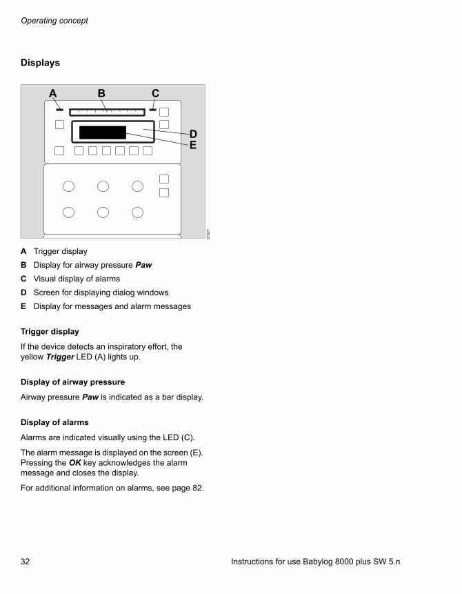
Displays
A Trigger display
B Display for airway pressure Paw
C Visual display of alarms
D Screen for displaying dialog windows
E Display for messages and alarm messages
Trigger display
If the device detects an inspiratory effort, the yellow Trigger LED (A) lights up.
Display of airway pressure
Airway pressure Paw is indicated as a bar display.
Display of alarms
Alarms are indicated visually using the LED (C).
The alarm message is displayed on the screen (E). Pressing the OK key acknowledges the alarm message and closes the display.
For additional information on alarms, see page 82.
21
62
7
A B C
ED

Instructions for use Babylog 8000 plus SW 5.n 33
Operating concept
Dialog windows
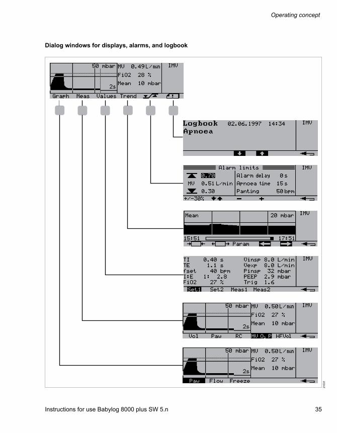
Dialog window layout
A Graphic field, displays the pressure waveform or flow waveform
B Measured value field, numeric display of measured values
C Status field, displays the current ventilation mode and other status information
D Row displaying the current assignments of the 6 variable keys under the screen
Opening dialog windows
The dialog windows can be opened using the following keys:
– Keys with fixed functions
– Vent. Mode
– Vent. Option
– Cal. Config.
– 6 keys with variable functions
Press a key to open the associated dialog window.
Main screen
The main screen is displayed after the device is switched on.
The following information is displayed on the main screen:
– Pressure waveform or flow waveform
– 3 measured values
– Ventilation mode
– Assignment of the 6 variable keys
The measured values to be displayed can be selected, see page 87. The waveform to be displayed can be selected, see page 87.
The set pressure limitation Pinsp (A) is displayed in the pressure waveform. The set expiratory time TE (B) is displayed in the pressure and flow waveforms.
21
62
9A B C D
20
92
3A B

Operating concept
34 Instructions for use Babylog 8000 plus SW 5.n
Overview of dialog windows
Dialog windows for ventilation
21
02
9
Instructions for use Babylog 8000 plus SW 5.n 35
Operating concept
Dialog windows for displays, alarms, and logbook
21
03
1

Operating concept
36 Instructions for use Babylog 8000 plus SW 5.n
Dialog windows for calibration and configuration
21
03
2

Instructions for use Babylog 8000 plus SW 5.n 37
Assembly and preparation
Assembly and preparation
Safety information ......................................... 38
Preparing the trolley...................................... 38
Safety information............................................ 38Load and stability............................................. 38Mounting the device on the trolley................... 39Parking the trolley............................................ 40
Mounting an additional monitor................... 40
Information on mounting.................................. 40Graphic Screen................................................ 40
Preparing the ventilator ................................ 42
Installing and replacing the O2 sensor............. 42Installing the expiratory valve .......................... 42Safety information on breathing circuits and additional components..................................... 43Preparing the breathing gas humidifier............ 43Attaching the bacterial filter ............................. 44Attaching the breathing hoses......................... 44Attaching the Y-piece and the flow sensor ...... 46Replacing the flow sensor insert...................... 47Connecting the test lung.................................. 47
Connecting a gas analyzer ........................... 48
Connecting the sample line ............................. 48
Establishing the gas supply ......................... 49
Gas supply from a central gas supply system. 49
Establishing the power supply..................... 50
Establishing the mains power supply .............. 50
MEDIBUS protocol......................................... 51
Connecting the external device for MEDIBUS. 51Configuring the interface ................................. 51
Establishing potential equalization ............. 52
Connecting the potential equalization cable .... 52
Transport within the hospital ....................... 53
Increasing stability ........................................... 53
Assembly and preparation
38 Instructions for use Babylog 8000 plus SW 5.n
Safety information
Preparing the trolley
Safety information
Load and stability
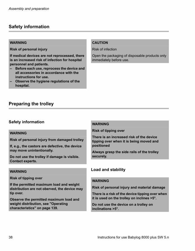
WARNING
Risk of personal injury
If medical devices are not reprocessed, there is an increased risk of infection for hospital personnel and patients.– Before each use, reprocess the device and
all accessories in accordance with the instructions for use.
– Observe the hygiene regulations of the hospital.
CAUTION
Risk of infection
Open the packaging of disposable products only immediately before use.
WARNING
Risk of personal injury from damaged trolley
If, e.g., the castors are defective, the device may move unintentionally.
Do not use the trolley if damage is visible. Contact experts.
WARNING
Risk of tipping over
If the permitted maximum load and weight distribution are not oberved, the device may tip over.
Observe the permitted maximum load and weight distribution, see ''Operating characteristics'' on page 139.
WARNING
Risk of tipping over
There is an increased risk of the device tipping over when it is being moved and positioned
Always grasp the side rails of the trolley securely.
WARNING
Risk of personal injury and material damage
There is a risk of the device tipping over when it is used on the trolley on inclines >5°.
Do not use the device on a trolley on inclinations >5°.

Instructions for use Babylog 8000 plus SW 5.n 39
Assembly and preparation
The maximum load of the trolley must not exceed 100 kg (220 lbs).
The following maximum loads apply to the individual sections:
Mounting the device on the trolley
Mounting the device on the trolley
1 Lock the brakes on the trolley and check the brake function.
2 Tilt the device forward.
3 Insert the front tabs in the grooves in the mounting plate.
4 Lower the device, insert the rear tabs in the grooves in the mounting plate, and secure the device with knurled screws at the rear.
22
54
7
Range Maximum load Example
A Device holder
40 kg (88 lbs) (of which max. 5 kg (11 lbs) on each lateral standard rail)
Device, patient monitor with holder, hinged arm
B Holder 10 kg (22 lbs) Breathing gas humidifier or medication nebulizer
C Base plate 50 kg (110 lbs) Ambient air compressor
5°
A
B
C
WARNING
Risk of personal injury and damage to equipment
If the device is not mounted securely to the trolley, it may fall off the trolley.
Mount the device securely. Check for secure fit.
20
90
1
Assembly and preparation
40 Instructions for use Babylog 8000 plus SW 5.n
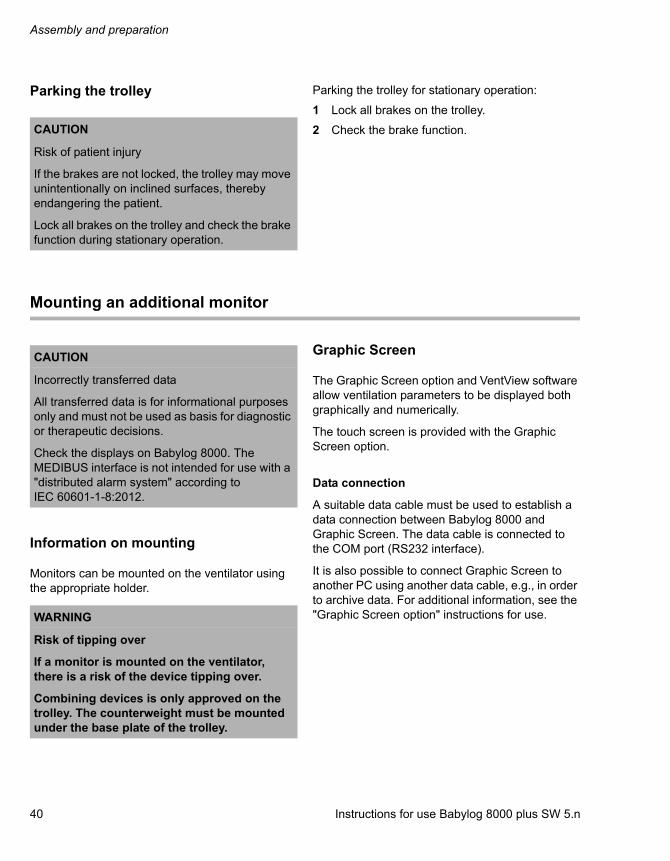
Parking the trolley Parking the trolley for stationary operation:
1 Lock all brakes on the trolley.
2 Check the brake function.
Mounting an additional monitor
Information on mounting
Monitors can be mounted on the ventilator using the appropriate holder.
Graphic Screen
The Graphic Screen option and VentView software allow ventilation parameters to be displayed both graphically and numerically.
The touch screen is provided with the Graphic Screen option.
Data connection
A suitable data cable must be used to establish a data connection between Babylog 8000 and Graphic Screen. The data cable is connected to the COM port (RS232 interface).
It is also possible to connect Graphic Screen to another PC using another data cable, e.g., in order to archive data. For additional information, see the "Graphic Screen option" instructions for use.
CAUTION
Risk of patient injury
If the brakes are not locked, the trolley may move unintentionally on inclined surfaces, thereby endangering the patient.
Lock all brakes on the trolley and check the brake function during stationary operation.
CAUTION
Incorrectly transferred data
All transferred data is for informational purposes only and must not be used as basis for diagnostic or therapeutic decisions.
Check the displays on Babylog 8000. The MEDIBUS interface is not intended for use with a "distributed alarm system" according to IEC 60601-1-8:2012.
WARNING
Risk of tipping over
If a monitor is mounted on the ventilator, there is a risk of the device tipping over.
Combining devices is only approved on the trolley. The counterweight must be mounted under the base plate of the trolley.
Instructions for use Babylog 8000 plus SW 5.n 41
Assembly and preparation
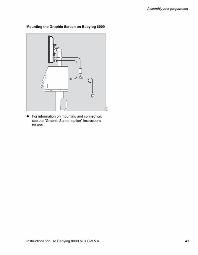
Mounting the Graphic Screen on Babylog 8000
For information on mounting and connection, see the "Graphic Screen option" instructions for use.
22
71
5

Assembly and preparation
42 Instructions for use Babylog 8000 plus SW 5.n
Preparing the ventilator
Installing and replacing the O2 sensor
The O2 sensor must be installed in the device before its first use.
If calibration is not possible because the O2 sensor is spent, the O2 sensor must be replaced.
Replacing the O2 sensor
For information on disposing of the spent O2 sensor, see chapter ''Disposal of O2 sensors'' on page 129.
1 Unscrew both slotted screws on the right side of the cover.
2 Remove the cover.
3 Remove the spent O2 sensor and dispose of it.
4 Insert the new O2 sensor. The circular conductors must face the cover.
5 Snap the cover into place and tighten both screws.
6 After a warm-up time of 15 minutes, carry out the calibration of the O2 sensor, see page 94.
Installing the expiratory valve
Condition: A sterile expiratory valve must be used.
1 Tilt the rocker lever (A) up.
2 Slide the expiratory valve onto the guide rods as far as possible.
3 Tilt the rocker lever down. The expiratory valve is locked in place.
4 Connect the muffler (B) to the exhaust port of the expiratory valve.
20
90
4
WARNING
Risk of patient injury
Expiratory valves that are damp or have not been reprocessed may impair device function and endanger the patient.
Only use properly reprocessed expiratory valves which have been sufficiently dried.
20
90
3
A
B
Instructions for use Babylog 8000 plus SW 5.n 43
Assembly and preparation
Safety information on breathing circuits and additional components
Additional components in the breathing circuit can increase the inspiratory and expiratory resistance values and exceed standard requirements.
Examples of additional components:
– Bacterial filters, inspiratory and expiratory
– CO2 cuvettes
– Coaxial hoses
Using bacterial filters
The ventilator is designed to minimize the patient's work of breathing. The use of bacterial filters requires particular care and monitoring by the user. Especially during medication nebulization and humidification, the resistance of the expiratory bacterial filter may increase gradually.
Consequences of high resistance
High resistance values during assisted ventilation lead to increased work of breathing and trigger effort. Under unfavorable conditions, this can lead to an undesirable, intrinsic PEEP, which can be recognized by the fact that the expiratory flow does not return to baseline at the end of expiration. If the PEEP is unacceptably high, this is indicated by an alarm. This indicates that the measured PEEP is more than 4 mbar (4 cmH2O) above the set PEEP. Check the bacterial filter and replace it if this is the cause of the PEEP alarm. If the end-expiratory flow is high, the alarm threshold increases to a measured PEEP value of up to 12 mbar (12 cmH2O).
Monitoring resistance
Because the device cannot measure resistance at the patient connection, carry out the following measures:
Check the patient's condition regularly.
Monitor the device's measured values for volume and resistance.
Observe the instructions for use for the bacterial filters and breathing circuits in use.
Preparing the breathing gas humidifier
Condition: The combination of breathing gas humidifier and Babylog 8000 must not impair the safety and function of either device.
Prepare the breathing gas humidifier in accordance with the corresponding instructions for use.
CAUTION
Increased compliance or resistance
Additional components in the breathing circuit such as bacterial filters or CO2 cuvettes increase the dead space, compliance, and resistance in the breathing circuit. Depending on the ventilation mode, either flow or pressure increases.
Particular care and monitoring are required when using additional components.

Assembly and preparation
44 Instructions for use Babylog 8000 plus SW 5.n
Attaching the bacterial filter
Conditions:
– Kit 8410230 must be used.
– The instructions for use for the bacterial filter must be observed.
1 Attach the breathing hose (A) 0.25 m (9.8 in) onto the inspiratory port.
2 Insert the adapter Ø15/Ø22 (B) into the breathing hose.
3 Attach the bacterial filter (C) onto the adapter.
4 Insert the catheter connector size II (D) into the bacterial filter.
5 Attach the breathing hoses.
Attaching the breathing hoses
Conditions:
– The breathing circuit in use must be suitable for the individual patient.
– When no incubator is being used, a hinged arm with clamp must be used.
CAUTION
Risk of contaminating the device
In the event of device failure, expiratory air may enter the device via the inspiratory line.
Use an inspiratory bacterial filter.
20
90
9
A
B
C
D
WARNING
Risk of electric shock and fire
The use of antistatic or conductive breathing hoses increases the risk of electric shock to the patient and of fire in an oxygen-enriched environment.
Do not use antistatic or conductive breathing hoses.
CAUTION
Humidification is ineffective if the inspiratory and expiratory ports are reversed.
Attach the breathing hoses correctly.

Instructions for use Babylog 8000 plus SW 5.n 45
Assembly and preparation
Attaching and removing the breathing hoses
When attaching and removing the breathing hoses, always hold them at the connection sleeve and not at the coil reinforcement.
Attaching the breathing hoses when no incubator is being used
1 Place the clamp of the hinged arm on the lateral standard rail of the trolley and tighten the screws. Depending on the position of the device relative to the bed, the hinged arm can be fitted to the left or right side.
2 Rotate the inspiratory and expiratory ports down or in the direction of the patient.
3 Connect the breathing hoses to the inspiratory and expiratory ports. Observe the hose lengths.
4 Install the water trap and place it vertically.
Attaching the breathing hoses when being used on the Dräger Incubator 8000 or Caleo
1 Connect the breathing hoses to the inspiratory and expiratory ports. Observe the hose lengths.
2 Install the water trap and place it vertically.
3 Mount the holder for breathing hoses in the incubator.
4 Press the rubber connection sleeves on the breathing hoses into the clamp on the holder.
20
90
7
21
90
92
09
08
Assembly and preparation
46 Instructions for use Babylog 8000 plus SW 5.n
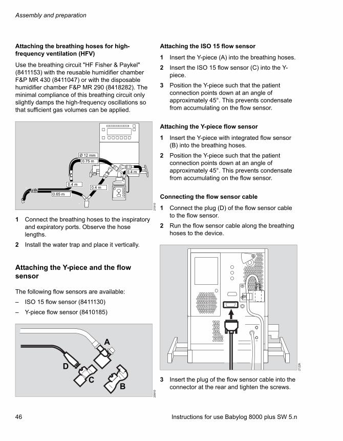
Attaching the breathing hoses for high-frequency ventilation (HFV)
Use the breathing circuit "HF Fisher & Paykel" (8411153) with the reusable humidifier chamber F&P MR 430 (8411047) or with the disposable humidifier chamber F&P MR 290 (8418282). The minimal compliance of this breathing circuit only slightly damps the high-frequency oscillations so that sufficient gas volumes can be applied.
1 Connect the breathing hoses to the inspiratory and expiratory ports. Observe the hose lengths.
2 Install the water trap and place it vertically.
Attaching the Y-piece and the flow sensor
The following flow sensors are available:
– ISO 15 flow sensor (8411130)
– Y-piece flow sensor (8410185)
Attaching the ISO 15 flow sensor
1 Insert the Y-piece (A) into the breathing hoses.
2 Insert the ISO 15 flow sensor (C) into the Y-piece.
3 Position the Y-piece such that the patient connection points down at an angle of approximately 45°. This prevents condensate from accumulating on the flow sensor.
Attaching the Y-piece flow sensor
1 Insert the Y-piece with integrated flow sensor (B) into the breathing hoses.
2 Position the Y-piece such that the patient connection points down at an angle of approximately 45°. This prevents condensate from accumulating on the flow sensor.
Connecting the flow sensor cable
1 Connect the plug (D) of the flow sensor cable to the flow sensor.
2 Run the flow sensor cable along the breathing hoses to the device.
3 Insert the plug of the flow sensor cable into the connector at the rear and tighten the screws.
21
91
02
09
10
A
BC
D
21
22
6
Instructions for use Babylog 8000 plus SW 5.n 47
Assembly and preparation
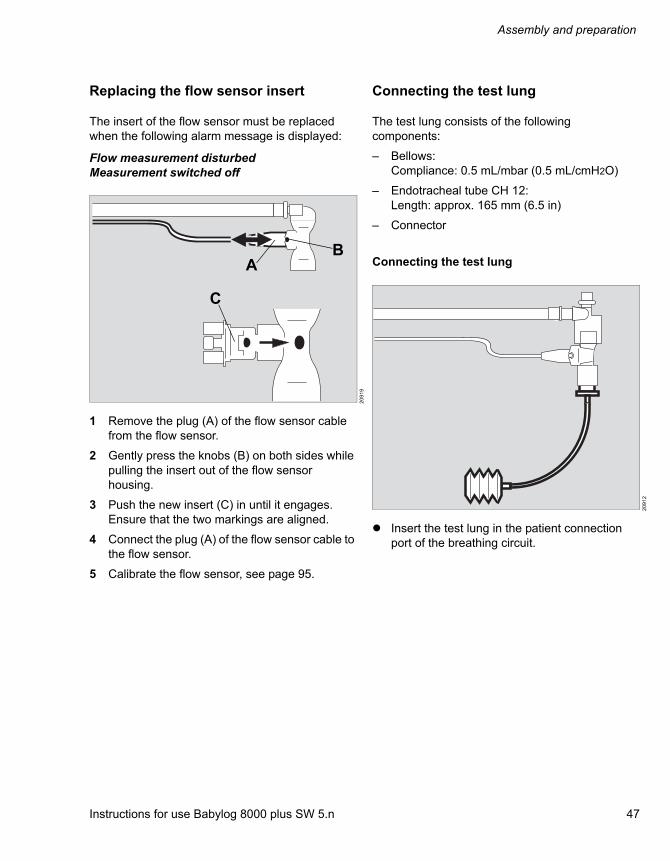
Replacing the flow sensor insert
The insert of the flow sensor must be replaced when the following alarm message is displayed:
Flow measurement disturbed Measurement switched off
1 Remove the plug (A) of the flow sensor cable from the flow sensor.
2 Gently press the knobs (B) on both sides while pulling the insert out of the flow sensor housing.
3 Push the new insert (C) in until it engages. Ensure that the two markings are aligned.
4 Connect the plug (A) of the flow sensor cable to the flow sensor.
5 Calibrate the flow sensor, see page 95.
Connecting the test lung
The test lung consists of the following components:
– Bellows:Compliance: 0.5 mL/mbar (0.5 mL/cmH2O)
– Endotracheal tube CH 12:Length: approx. 165 mm (6.5 in)
– Connector
Connecting the test lung
Insert the test lung in the patient connection port of the breathing circuit.
20
91
9
AB
C
20
91
2

Assembly and preparation
48 Instructions for use Babylog 8000 plus SW 5.n
Connecting a gas analyzer
Condition: The adapter with safety valve (8412448) must be in use.
Connecting the sample line
Connect the sample line to the adapter with safety valve. In order to prevent condensate from accumulating, the Luer Lock connector must face upwards.
CAUTION
Risk of patient injury
When gas analyzers are being used, a blocked inspiratory hose can lead to negative pressure in the airways.
Only connect the sample line of the gas analyzer using the adapter with safety valve (8412448).
20
91
3
Instructions for use Babylog 8000 plus SW 5.n 49
Assembly and preparation
Establishing the gas supply
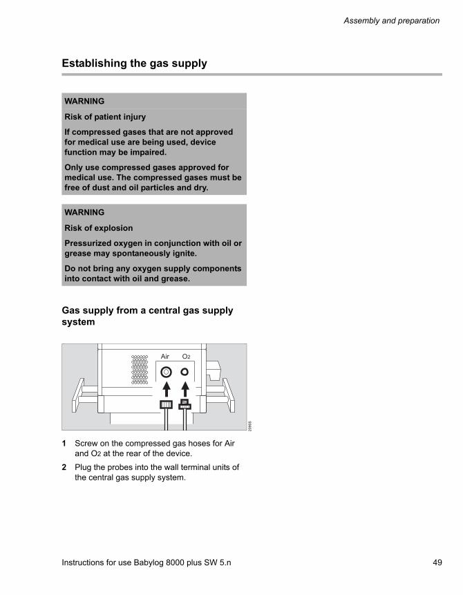
Gas supply from a central gas supply system
1 Screw on the compressed gas hoses for Air and O2 at the rear of the device.
2 Plug the probes into the wall terminal units of the central gas supply system.
WARNING
Risk of patient injury
If compressed gases that are not approved for medical use are being used, device function may be impaired.
Only use compressed gases approved for medical use. The compressed gases must be free of dust and oil particles and dry.
WARNING
Risk of explosion
Pressurized oxygen in conjunction with oil or grease may spontaneously ignite.
Do not bring any oxygen supply components into contact with oil and grease.
20
90
5
Air O2

Assembly and preparation
50 Instructions for use Babylog 8000 plus SW 5.n
Establishing the power supply
The device is designed for connection to the hospital's mains power supply.
Establishing the mains power supply
Condition:The mains voltage must be within the voltage range indicated on the rating plate:Either: 100 V to 127 VOr: 220 V to 240 V
Insert the mains plug into the mains power socket.
WARNING
Risk of electric shock and of device failure
If the device is plugged into a socket with the incorrect mains voltage or one that has no protective earth, the user may be endangered and the device may be damaged.
The power cable may only be connected to a socket with protective earth, see chapter ''Technical data''.
Instructions for use Babylog 8000 plus SW 5.n 51
Assembly and preparation
MEDIBUS protocol
MEDIBUS is a software protocol for data transfer between Babylog 8000 and other medical devices (e.g., patient monitors) or other devices (e.g., computers for data management systems).
Requirements for the combination of Babylog 8000 and an external device, see ''Device combinations'' on page 9.
Observe the following documents:
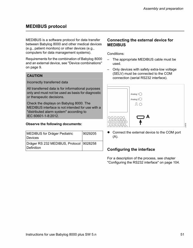
Connecting the external device for MEDIBUS
Conditions:
– The appropriate MEDIBUS cable must be used.
– Only devices with safety extra-low voltage (SELV) must be connected to the COM connection (serial RS232 interface).
Connect the external device to the COM port (A).
Configuring the interface
For a description of the process, see chapter ''Configuring the RS232 interface'' on page 104.
CAUTION
Incorrectly transferred data
All transferred data is for informational purposes only and must not be used as basis for diagnostic or therapeutic decisions.
Check the displays on Babylog 8000. The MEDIBUS interface is not intended for use with a "distributed alarm system" according to IEC 60601-1-8:2012.
MEDIBUS for Dräger Pediatric Devices
9029205
Dräger RS 232 MEDIBUS, Protocol Definition
9028258
21
87
9
A
Assembly and preparation
52 Instructions for use Babylog 8000 plus SW 5.n
Establishing potential equalization
Potential equalization allows electrical potential differences between devices to be reduced.
Potential equalization does not replace the protective earth connection.
During operation, the potential equalization connectors must be readily accessible and the connection must be able to be disconnected without the use of tools.
Connecting the potential equalization cable
1 Connect the potential equalization cable to the potential equalization pin on the device.
2 Connect the potential equalization cable to a hospital potential equalization connection (e.g., wall, ceiling supply unit, operating table).
Instructions for use Babylog 8000 plus SW 5.n 53
Assembly and preparation
Transport within the hospital
Transport refers to any movement of the medical device without the patient that does not solely serve to position the medical device.
Increasing stability
1 Set the hinged arm to minimum extension.
2 Empty the water container of the breathing gas humidifier.
3 Do not attach any additional parts to the lateral standard rails.
4 Remove the monitor if there is one.
5 Grasp the device firmly by the lateral standard rails and push the device in longitudinal direction.

Getting started
54 Instructions for use Babylog 8000 plus SW 5.n
Getting started
Safety information ......................................... 55
Switching on the ventilator .......................... 55
Starting ventilation........................................... 56
Charging the battery for the power supply failure alarm ................................................... 57
Checking readiness for operation ............... 58
Device check after reprocessing ..................... 58Device check immediately before using the device on a patient .......................................... 60Checking the speaker and LEDs..................... 61
Instructions for use Babylog 8000 plus SW 5.n 55
Getting started
Safety information
Switching on the ventilator
Conditions:
– The device has been reprocessed and assembled ready for operation.
– The mains power supply and the gas supply are connected.
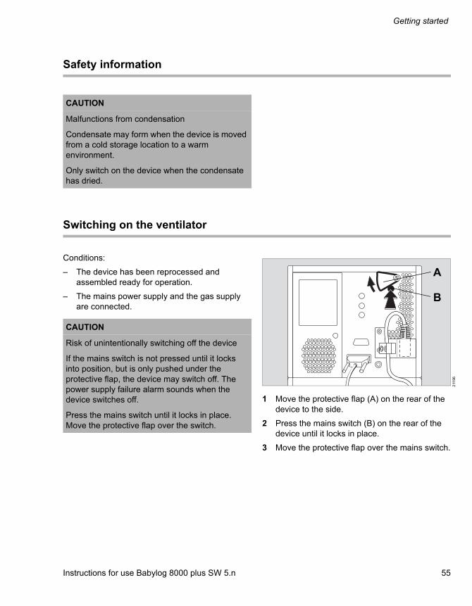
1 Move the protective flap (A) on the rear of the device to the side.
2 Press the mains switch (B) on the rear of the device until it locks in place.
3 Move the protective flap over the mains switch.
CAUTION
Malfunctions from condensation
Condensate may form when the device is moved from a cold storage location to a warm environment.
Only switch on the device when the condensate has dried.
CAUTION
Risk of unintentionally switching off the device
If the mains switch is not pressed until it locks into position, but is only pushed under the protective flap, the device may switch off. The power supply failure alarm sounds when the device switches off.
Press the mains switch until it locks in place. Move the protective flap over the switch.
211
96
A
B

Getting started
56 Instructions for use Babylog 8000 plus SW 5.n
A self-test is carried out. All LEDs light up. A continuous tone and an alarm tone sequence sound briefly.
After the self-test is complete, the device information is displayed, see page 99.
Then the main screen is displayed.
The device is ready for operation after approx. 15 seconds. If the automatic calibration of the O2 sensor is activated, O2 measurement is only available after 5 minutes.
Starting ventilation
1 Press the Vent. Mode key (A).
2 Press the IPPV/IMV key (B).
3 Press the On key.
4 Press the key.
The symbol for alarm limits (C) flashes.
Set the alarm limits, see page 84.
The Calibrate flow sensor! alarm message is displayed.
Calibrate the flow sensor, see page 95.
20
93
7
20
91
52
09
39
A
B
C
Instructions for use Babylog 8000 plus SW 5.n 57
Getting started
Charging the battery for the power supply failure alarm
The battery is automatically charged when the device is switched on.
Charge the battery for at least 30 minutes before the first use and after being stored.
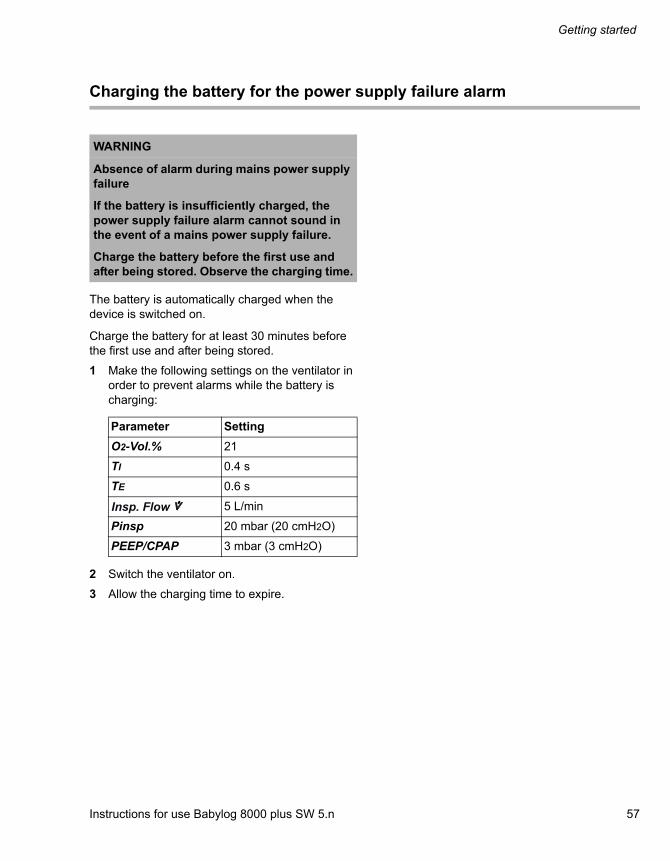
1 Make the following settings on the ventilator in order to prevent alarms while the battery is charging:
2 Switch the ventilator on.
3 Allow the charging time to expire.
WARNING
Absence of alarm during mains power supply failure
If the battery is insufficiently charged, the power supply failure alarm cannot sound in the event of a mains power supply failure.
Charge the battery before the first use and after being stored. Observe the charging time.
Parameter Setting
O2-Vol.% 21
TI 0.4 s
TE 0.6 s
5 L/min
Pinsp 20 mbar (20 cmH2O)
PEEP/CPAP 3 mbar (3 cmH2O)
Insp. Flow

Getting started
58 Instructions for use Babylog 8000 plus SW 5.n
Checking readiness for operation
Readiness for operation is checked as part of the device check.
After reprocessing, carry out the following steps of the device check:
– Check the power supply failure alarm
– Check the gas failure alarm
– Check the IPPV ventilation mode
– Check the PEEP
– Check the alarm limits
Immediately before using the device on a patient, carry out the following steps of the device check:
– Check the breathing circuit for leaks
– Calibrate the flow sensor
– Check the ventilation functions
– Check the apnea alarm
– Check the alarm for minute volume
– Check the alarm for airway pressure
Device check after reprocessing
Carry out the device check after each reprocessing in order to check the operability of the device.
Conditions:
– The device must be prepared.
– The expiratory valve, breathing circuit, and flow sensor must be correctly connected.
– The test lung must be connected.
Checking the power supply failure alarm
1 Unplug the mains cable.
2 Switch the device on, see page 55.
The power supply failure alarm must sound and remain constant for approx. 20 seconds. If the alarm tone sounds less than 20 seconds, charge the battery, see page 57.
3 Move the protective flap on the mains switch to the side. Press the mains switch until it locks in place and release it.
The power supply failure alarm is silenced.
4 Plug the mains cable back in.
Checking the gas failure alarm
1 Switch the device on, see page 55.
2 Set the IPPV/IMV ventilation mode.
3 Set the following alarm limits:
Checking the O2 alarm:
1 Set the O2-Vol.% setting knob to 60 %.
WARNING
Risk of patient injury
Before using the device on a patient, the device check must be carried out. If a malfunction is detected, the patient may be endangered.
Do not start ventilation until after the device check has been successfully carried out.
MV 0 L/min
MV 15 L/min

Instructions for use Babylog 8000 plus SW 5.n 59
Getting started
2 Disconnect the probe of the O2 compressed gas hose from the wall terminal unit of the central gas supply system.
The visual alarm signal flashes red, the acoustic alarm signal sounds, and the alarm message O2 pressure low is displayed.
3 Plug the probe into the wall terminal unit of the central gas supply system.
The visual alarm signal goes out, the acoustic alarm signal is silenced, and the alarm message is no longer displayed.
Checking the compressed air alarm:
1 Disconnect the probe of the compressed air gas hose from the wall terminal unit of the central gas supply system.
The visual alarm signal flashes red, the acoustic alarm signal sounds, and the alarm message Medical air low is displayed.
2 Plug the probe into the wall terminal unit of the central gas supply system.
The visual alarm signal goes out, the acoustic alarm signal is silenced, and the alarm message is no longer displayed.
Checking the IPPV ventilation mode
1 Set the following ventilation parameters:
2 On the main screen, press the Meas key.
3 Press the Paw key.
The displayed values must be within the following ranges:
Checking the PEEP
1 Set the PEEP/CPAP setting knob to 10.
2 Press the OK key.
3 On the main screen, press the Meas key.
4 Press the Paw key.
The displayed values must be within the following ranges:
Checking the alarm limits
Checking apnea monitoring:
Set the CPAP ventilation mode.
After a maximum of 30 seconds, the visual alarm signal flashes red, the acoustic alarm signal sounds, and one of the following alarm messages is displayed:
Checking the alarm limits for airway pressure:
1 Set the IPPV/IMV ventilation mode.
Parameter Setting
Ventilation mode IPPV/IMV
O2-Vol.% 21
10
TI 0.4
TE 0.6
Pinsp 20
PEEP/CPAP 0
Insp. Flow
Measured value
Permissible range
Peak 18 to 22 mbar (18 to 22 cmH2O)
Mean 6 to 10 mbar (6 to 10 cmH2O)
PEEP –1.5 to 1.5 mbar(–1.5 to 1.5 cmH2O)
Measured value
Permissible range
Peak 18 to 22 mbar (18 to 22 cmH2O)
Mean 12 to 16 mbar (12 to 16 cmH2O)
PEEP 8 to 12 mbar (8 to 12 cmH2O)
– Apnoea
– MV low
Getting started
60 Instructions for use Babylog 8000 plus SW 5.n
2 Kink the expiratory breathing hose.
The visual alarm signal flashes red, the acoustic alarm signal sounds, and one of the following alarm messages is displayed:
3 Release the expiratory breathing hose.
4 Disconnect the connector on the Y-piece.
The visual alarm signal flashes red, the acoustic alarm signal sounds, and one of the following alarm messages is displayed:
5 Set the PEEP/CPAP setting knob back to 0.
6 Reconnect the test lung.
Checking the breathing gas humidifier
Check the breathing gas humidifier in accordance with the corresponding instructions for use.
Device check immediately before using the device on a patient
Carry out the device check immediately before using the device on a patient in order to check the operability of the device.
Conditions:
– Gas supply must be ensured.
– The expiration valve, breathing circuit, and flow sensor must be correctly connected.
– The test lung must be connected.
Checking the breathing circuit for leaks
1 Switch the device on.
2 Press the OK key. The alarm message Calibrate flow sensor! is no longer displayed.
3 Set the following ventilation parameters:
4 Press the OK key.
5 Press and hold the man. Insp. key. The bar display must read (80 ±2) mbar.
Calibrating the flow sensor
Calibrate the flow sensor, see page 95.
If calibration is successful, a confirmation is displayed on the screen.
Checking the ventilation functions
1 Set the following alarm limits:
– Hose kinked?
– Airway pressure high Inspiration cancelled
– Airway pressure low
– Leak in hose system? Check setting!
Parameter Setting
Ventilation mode CPAP
2
Pinsp 80
MV 0 L/min
MV 15 L/min
Insp. Flow
Instructions for use Babylog 8000 plus SW 5.n 61
Getting started
2 Set the following ventilation parameters and press the OK key. Make sure that the results conform to the values in the following table.
Checking the apnea alarm
Set the CPAP ventilation mode.
After a maximum of 30 seconds the alarm message Apnoea is displayed and the alarm signal sounds.
Checking the alarm for minute volume
1 Set the IPPV/IMV ventilation mode.
2 Set the MV alarm limit: 1 L/min
After a maximum of 30 seconds the alarm message MV low is displayed and the alarm signal sounds.
3 Set the MV and MV alarm limits to the desired values.
Checking the alarm for airway pressure
1 Kink the expiratory breathing hose.
The alarm signal sounds and one of the following alarm messages is displayed:
Ventilation is interrupted and the bar display shows an airway pressure of <5 mbar. After approx. 5 seconds, ventilation is continued and immediately interrupted again. The procedure repeats.
2 Release the expiratory breathing hose.
3 Disconnect the connector on the Y-piece.
After a maximum of 15 seconds the alarm signal sounds and one of the following alarm messages is displayed:
The bar display shows an airway pressure of ≤ 4 mbar.
4 Set the PEEP/CPAP setting knob back to 0.
5 Reconnect the Y-piece.
Checking the speaker and LEDs
The speaker and LEDs can also be checked while the device is in operation.
Press and hold the OK key for approx. 2 seconds.
All LEDs light up and a continuous tone sounds as long as the key is pressed.
Parameter Setting Result in Paw bar display
Ventilation mode
IPPV -
Pinsp 20 Inspiratory: (20 ±4) mbar
10 Ventilation corre-sponds with the set ratio of TI and TE.
TI 0.4
TE 0.6
PEEP/CPAP 0 Expiratory: (0 ±2) mbar
PEEP/CPAP 10 Expiratory: (10 ±2) mbar
Insp. Flow
– Airway pressure high Inspiration cancelled
– Hose kinked?
– Airway pressure low
– Leak in hose system? Check setting!

Operation
62 Instructions for use Babylog 8000 plus SW 5.n
Operation
Setting ventilation ......................................... 63
Ventilation modes and ventilation parameters 63Trigger threshold ............................................. 64Ventilation with pressure plateau .................... 64Ventilation without pressure plateau ............... 65Ventilation with CPAP ..................................... 65Ventilation with separate expiratory flow ......... 66Ventilation with Volume Guarantee ................. 66High-frequency ventilation............................... 67
Endotracheal suction .................................... 68
Closed suction................................................. 68
Manual inspiration......................................... 69
Starting manual inspiration.............................. 69
Medication nebulization................................ 70
Safety information on medication nebulization 70Preparing and removing the flow sensor......... 71Information on pneumatic medication nebulization ..................................................... 72Performing pneumatic medication nebulization........................................................................ 73Performing medication nebulization with an Aeroneb Pro nebulizer..................................... 75
Analog and digital interface ......................... 76
Data output...................................................... 76Transferring data to the patient monitor .......... 79
Terminating operation .................................. 80
Switching the ventilator off .............................. 80Removing the compressed gas hoses ............ 80

Instructions for use Babylog 8000 plus SW 5.n 63
Operation
Setting ventilation
Ventilation is set using the keys and setting knobs on the device and in the dialog windows. The settings can be made during ventilation. A detailed description of the process can be found in chapter ''Operating concept'' on page 28.
Ventilation modes and ventilation parameters
A detailed description of the ventilation modes and ventilation parameters can be found in chapters ''Description of ventilation modes'' on page 156 and ''Additional settings for ventilation'' on page 161.
SIMV, SIPPV, and PSV ventilation modes
If the patients becomes apneic, ventilation begins with the respiratory rate specified by TI and TE.
Ventilation parameters Ventilation mode
Location of setting control
CPAP IPPV/IMV SIMV SIPPV PSV
Setting knobs on device
O2-Vol.% X X X X X
TI X X X X X
TE X X X X X
X X X X X
Pinsp X X X X X
PEEP/CPAP X X X X X
Options dialog win-dow
Trigger X X X
Options > VIVE dia-log window
X X X X X
Options > VG dialog window
Vtset X X X
Options > HFV dialog window
Frequ. X X
Ampl. X X
Insp. Flow
ex
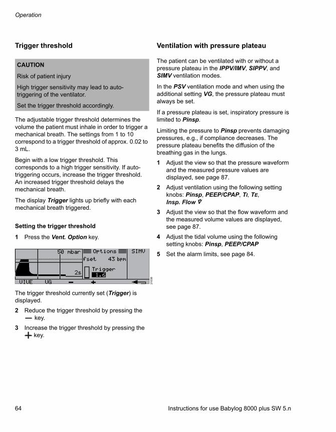
Operation
64 Instructions for use Babylog 8000 plus SW 5.n
Trigger threshold
The adjustable trigger threshold determines the volume the patient must inhale in order to trigger a mechanical breath. The settings from 1 to 10 correspond to a trigger threshold of approx. 0.02 to 3 mL.
Begin with a low trigger threshold. This corresponds to a high trigger sensitivity. If auto-triggering occurs, increase the trigger threshold. An increased trigger threshold delays the mechanical breath.
The display Trigger lights up briefly with each mechanical breath triggered.
Setting the trigger threshold
1 Press the Vent. Option key.
The trigger threshold currently set (Trigger) is displayed.
2 Reduce the trigger threshold by pressing the key.
3 Increase the trigger threshold by pressing the key.
Ventilation with pressure plateau
The patient can be ventilated with or without a pressure plateau in the IPPV/IMV, SIPPV, and SIMV ventilation modes.
In the PSV ventilation mode and when using the additional setting VG, the pressure plateau must always be set.
If a pressure plateau is set, inspiratory pressure is limited to Pinsp.
Limiting the pressure to Pinsp prevents damaging pressures, e.g., if compliance decreases. The pressure plateau benefits the diffusion of the breathing gas in the lungs.
1 Adjust the view so that the pressure waveform and the measured pressure values are displayed, see page 87.
2 Adjust ventilation using the following setting knobs: Pinsp, PEEP/CPAP, TI, TE,
3 Adjust the view so that the flow waveform and the measured volume values are displayed, see page 87.
4 Adjust the tidal volume using the following setting knobs: Pinsp, PEEP/CPAP
5 Set the alarm limits, see page 84.
CAUTION
Risk of patient injury
High trigger sensitivity may lead to auto-triggering of the ventilator.
Set the trigger threshold accordingly.
21
03
8
Insp. Flow

Instructions for use Babylog 8000 plus SW 5.n 65
Operation
Ventilation without pressure plateau
Not setting a pressure plateau is equivalent to volume-controlled ventilation. The peak pressure is determined by the settings TI and .
1 Adjust the view so that the pressure waveform and the measured pressure values are displayed, see page 87.
2 Adjust ventilation using the following setting knobs: PEEP/CPAP, TI, TE,
3 Adjust the view so that the flow waveform and the measured volume values are displayed, see page 87.
4 Adjust the tidal volume using the following setting knobs: TI,
5 Set the pressure limitation using the Pinsp setting knob.
6 Set the alarm limits, see page 84.
Ventilation with CPAP
In CPAP ventilation mode, the device applies continuous flow. The measured value Mean must conform to the set airway pressure. The measured values Peak and PEEP are not displayed.
1 Set the CPAP ventilation mode.
2 Adjust the view so that the flow waveform and the measured pressure values are displayed, see page 87.
3 Set the airway pressure to CPAP level with the PEEP/CPAP setting knob. Turn the setting knob slowly, otherwise the set value PEEP is not updated.
4 Set the ventilation parameter Pinsp approx. 5 mbar (5 cmH2O) higher than PEEP/CPAP.
5 Use the setting knob to set the flow .
6 Adjust the view so that the measured volume values are displayed, see page 87.
7 Check the volumes breathed spontaneously.
8 Set the alarm limits, see page 84.
CPAP with nasopharyngeal airway
Because breathing gas may escape through the mouth, it is not possible to monitor the minute volume or use apnea monitoring.
Deactivate flow monitoring or the MV and Apnoea time alarm limits.
For information on deactivating flow monitoring, see chapter ''Deactivating flow monitoring'' on page 97. For information on deactivating alarm limits, see chapter ''Deactivating alarm limits'' on page 85.
insp
Insp. Flow
Insp. Flow
Insp. Flowinsp
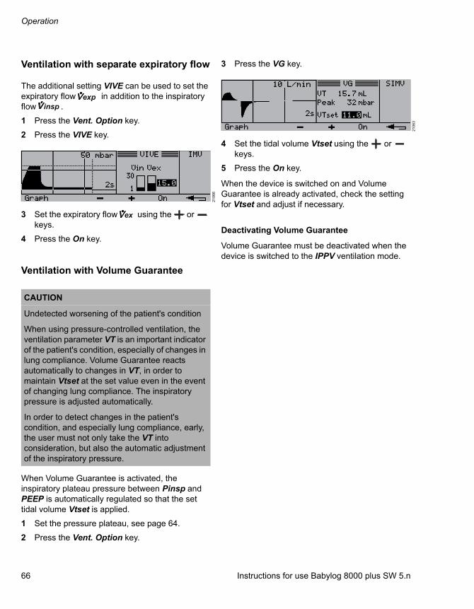
Operation
66 Instructions for use Babylog 8000 plus SW 5.n
Ventilation with separate expiratory flow
The additional setting VIVE can be used to set the expiratory flow in addition to the inspiratory flow .
1 Press the Vent. Option key.
2 Press the VIVE key.
3 Set the expiratory flow using the or keys.
4 Press the On key.
Ventilation with Volume Guarantee
When Volume Guarantee is activated, the inspiratory plateau pressure between Pinsp and PEEP is automatically regulated so that the set tidal volume Vtset is applied.
1 Set the pressure plateau, see page 64.
2 Press the Vent. Option key.
3 Press the VG key.
4 Set the tidal volume Vtset using the or keys.
5 Press the On key.
When the device is switched on and Volume Guarantee is already activated, check the setting for Vtset and adjust if necessary.
Deactivating Volume Guarantee
Volume Guarantee must be deactivated when the device is switched to the IPPV ventilation mode.
21
06
6
CAUTION
Undetected worsening of the patient's condition
When using pressure-controlled ventilation, the ventilation parameter VT is an important indicator of the patient's condition, especially of changes in lung compliance. Volume Guarantee reacts automatically to changes in VT, in order to maintain Vtset at the set value even in the event of changing lung compliance. The inspiratory pressure is adjusted automatically.
In order to detect changes in the patient's condition, and especially lung compliance, early, the user must not only take the VT into consideration, but also the automatic adjustment of the inspiratory pressure.
expinsp
ex
21
06
3

Instructions for use Babylog 8000 plus SW 5.n 67
Operation
High-frequency ventilation
1 Set the CPAP ventilation mode.
2 Press the Vent. Option key.
3 Press the HFV key.
4 Select the parameter Frequ. by pressing the key.
5 Set the frequency using the or key.
6 Select the parameter Ampl. by pressing the key.
7 Set the amplitude using the or key.
8 Press the On key.
9 Use the PEEP/CPAP setting knob to set the mean airway pressure to at least 3 mbar (3 cmH2O).
10 On the main screen, press the Values key.
11 Press the Meas2 key.
12 Monitor the tidal volume VThf and the diffusion coefficient DCO2 and adjust the amplitude and frequency if necessary.
Setting IMV mechanical breaths
High-frequency ventilation can be combined with conventional mechanical breaths to flush the dead space.
1 Set the IPPV/IMV ventilation mode.
2 Set high-frequency ventilation, see page 67.
3 Use the TI and TE setting knobs to set the duration and respiratory rate of the IMV mechanical breaths.
4 Set the pressure limitation of the IMV mechanical breaths with the Pinsp setting knob.
21
06
4
21
06
5

Operation
68 Instructions for use Babylog 8000 plus SW 5.n
Endotracheal suction
Closed suction
Closed suction is possible in all ventilation modes. An appropriate flow must be set for suction.
Set the appropriate flow with the setting knob.
WARNING
Development of atelectasis
If the suction catheter used is too large, air feed is blocked. The negative pressure accompanying suction can cause atelectasis to develop.
Select an appropriate suction catheter for suction.
Insp. Flow
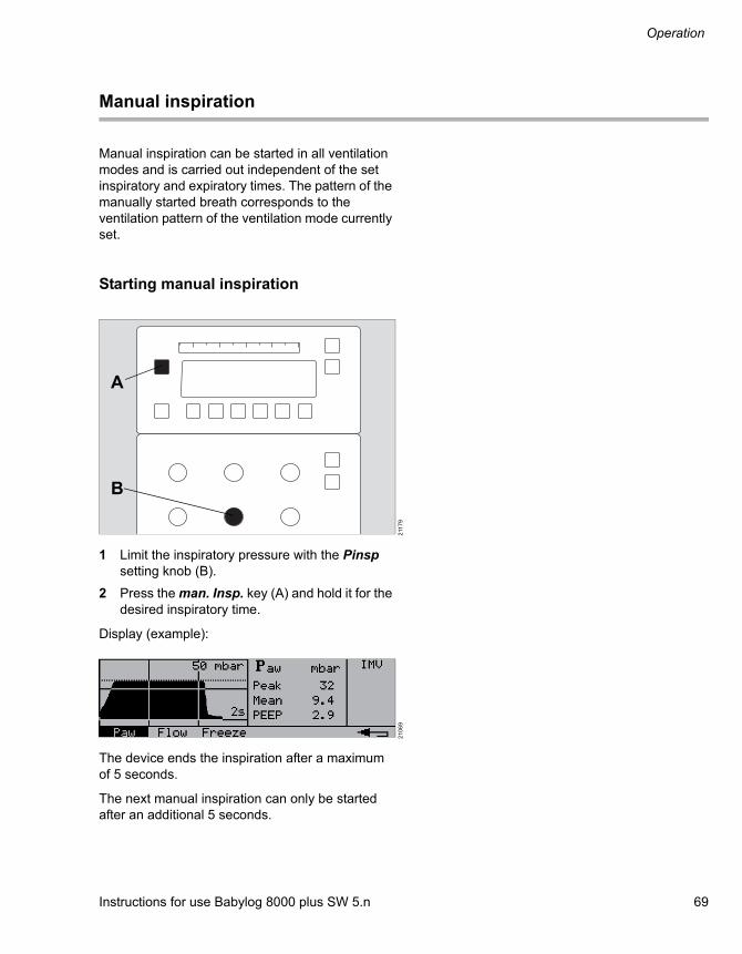
Instructions for use Babylog 8000 plus SW 5.n 69
Operation
Manual inspiration
Manual inspiration can be started in all ventilation modes and is carried out independent of the set inspiratory and expiratory times. The pattern of the manually started breath corresponds to the ventilation pattern of the ventilation mode currently set.
Starting manual inspiration
1 Limit the inspiratory pressure with the Pinsp setting knob (B).
2 Press the man. Insp. key (A) and hold it for the desired inspiratory time.
Display (example):
The device ends the inspiration after a maximum of 5 seconds.
The next manual inspiration can only be started after an additional 5 seconds.
211
79
21
06
9
A
B

Operation
70 Instructions for use Babylog 8000 plus SW 5.n
Medication nebulization
Safety information on medication nebulization
WARNING
Risk of fire
The flow sensor can ignite medications or other substances based on highly flammable substances.– Do not nebulize medications or other
substances that are easily flammable or spray them into the device.
– Do not use substances containing alcohol.– Do not allow flammable or explosive
substances to enter the breathing system or the breathing circuit.
CAUTION
Ventilation impaired
If unapproved pneumatic medication nebulizers are used, the delivered tidal volume and O2 concentration may deviate from the displayed values.
Only use medication nebulizers listed in the current list of accessories.
CAUTION
Ventilation impaired
If a bacterial filter is placed between the nebulizer and tube during medication nebulization, flow resistance may increase and impair ventilation.
Place the bacterial filter between the inspiratory valve and the nebulizer.
CAUTION
Ventilation impaired
If the nebulizer is left in the breathing circuit after use, ventilation may be impaired by unintentional medication nebulization.
Remove the nebulizer after use.
CAUTION
Ventilation impaired
Aerosols can impair the proper functioning of the expiratory valve.
When using medication nebulization, shorten the reprocessing cycles for the expiratory valve.
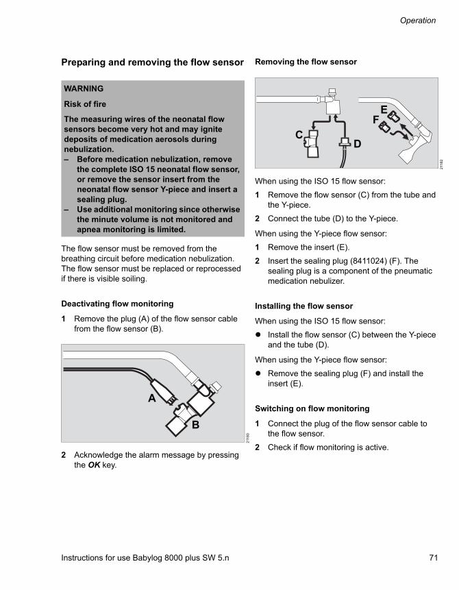
Instructions for use Babylog 8000 plus SW 5.n 71
Operation
Preparing and removing the flow sensor
The flow sensor must be removed from the breathing circuit before medication nebulization. The flow sensor must be replaced or reprocessed if there is visible soiling.
Deactivating flow monitoring
1 Remove the plug (A) of the flow sensor cable from the flow sensor (B).
2 Acknowledge the alarm message by pressing the OK key.
Removing the flow sensor
When using the ISO 15 flow sensor:
1 Remove the flow sensor (C) from the tube and the Y-piece.
2 Connect the tube (D) to the Y-piece.
When using the Y-piece flow sensor:
1 Remove the insert (E).
2 Insert the sealing plug (8411024) (F). The sealing plug is a component of the pneumatic medication nebulizer.
Installing the flow sensor
When using the ISO 15 flow sensor:
Install the flow sensor (C) between the Y-piece and the tube (D).
When using the Y-piece flow sensor:
Remove the sealing plug (F) and install the insert (E).
Switching on flow monitoring
1 Connect the plug of the flow sensor cable to the flow sensor.
2 Check if flow monitoring is active.
WARNING
Risk of fire
The measuring wires of the neonatal flow sensors become very hot and may ignite deposits of medication aerosols during nebulization.– Before medication nebulization, remove
the complete ISO 15 neonatal flow sensor, or remove the sensor insert from the neonatal flow sensor Y-piece and insert a sealing plug.
– Use additional monitoring since otherwise the minute volume is not monitored and apnea monitoring is limited.
211
80
A
B2
118
2
EF
CD

Operation
72 Instructions for use Babylog 8000 plus SW 5.n
Information on pneumatic medication nebulization
Medication nebulization may be used in all ventilation modes.
The medication nebulizer nebulizes continuously. The aerosol generated during expiration does not reach the lungs, however.
O2 concentration during nebulization
Air is used for medication nebulization. The delivered O2 concentration is therefore lower than the set O2 concentration.
If FiO2 must remain constant, set the O2 concentration using the nomogram.
Example:With an inspiratory flow of 10 L/min and a desired O2 concentration of 80 Vol.%, the O2-Vol.% setting knob must be set to 90 Vol.% during medication nebulization.
CAUTION
Reduced O2 concentration
Air is used for medication nebulization. The delivered O2 concentration is therefore lower than the set O2 concentration.
If required, set a higher inspiratory O2 concentration.
CAUTION
Insufficient medication nebulization
A medication nebulizer fault is not detected by Babylog 8000.– Check the correct functioning of the
medication nebulizer.– Check whether aerosol is generated.
21
911
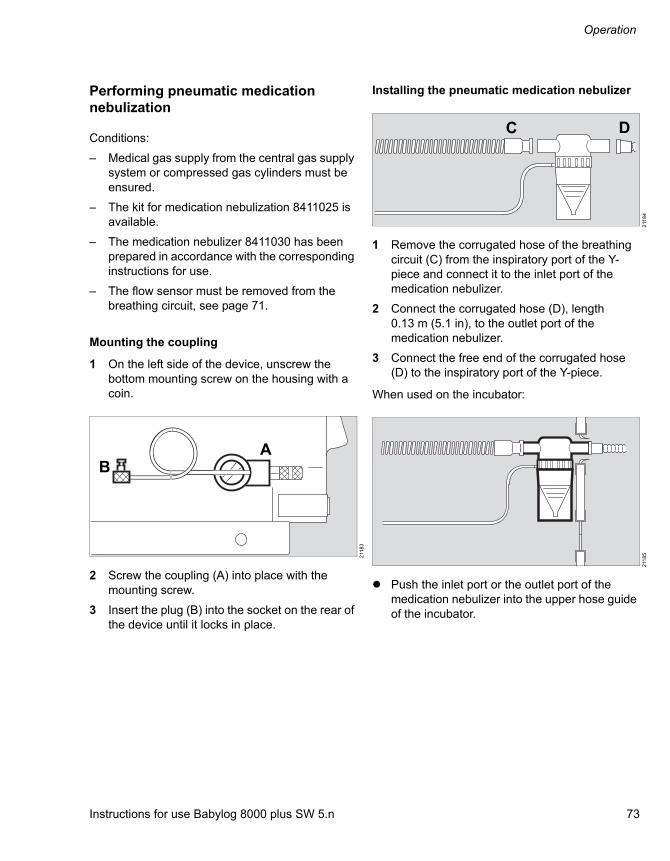
Instructions for use Babylog 8000 plus SW 5.n 73
Operation
Performing pneumatic medication nebulization
Conditions:
– Medical gas supply from the central gas supply system or compressed gas cylinders must be ensured.
– The kit for medication nebulization 8411025 is available.
– The medication nebulizer 8411030 has been prepared in accordance with the corresponding instructions for use.
– The flow sensor must be removed from the breathing circuit, see page 71.
Mounting the coupling
1 On the left side of the device, unscrew the bottom mounting screw on the housing with a coin.
2 Screw the coupling (A) into place with the mounting screw.
3 Insert the plug (B) into the socket on the rear of the device until it locks in place.
Installing the pneumatic medication nebulizer
1 Remove the corrugated hose of the breathing circuit (C) from the inspiratory port of the Y-piece and connect it to the inlet port of the medication nebulizer.
2 Connect the corrugated hose (D), length 0.13 m (5.1 in), to the outlet port of the medication nebulizer.
3 Connect the free end of the corrugated hose (D) to the inspiratory port of the Y-piece.
When used on the incubator:
Push the inlet port or the outlet port of the medication nebulizer into the upper hose guide of the incubator.
211
83
BA
211
84
211
85
C D

Operation
74 Instructions for use Babylog 8000 plus SW 5.n
When used without incubator:
1 Press the inlet port or the outlet port of the medication nebulizer into one side of the hose clip and the expiratory hose into the other.
2 Position the medication nebulizer vertically.
Preparing the medication nebulizer
Fill the medication nebulizer in accordance with the corresponding instructions for use.
Connecting the nebulizer hose
1 Insert the plug of the nebulizer hose into the socket (E) until it locks in place.
Babylog 8000 starts nebulization.
2 Check whether aerosol is generated.
Increasing the O2 concentration during nebulization
1 The required O2 concentration can be found on the nomogram, see page 72.
2 Increase the O2 concentration with the O2-Vol.% setting knob.
Terminating medication nebulization
1 Retract the socket (F) so that the plug disengages.
2 Remove any residual medication.
3 Remove the medication nebulizer and reprocess it in accordance with the corresponding instructions for use.
4 Set the O2-Vol.% setting knob to its original value.
5 Install the flow sensor, see page 71.
6 Switch flow monitoring on, see page 71.
7 If a bacterial filter is used to protect the expiratory valve, replace or remove the bacterial filter.
8 If no bacterial filter is used, attach a reprocessed expiratory valve, see page 42.
211
87
211
88
E
211
90
F
Instructions for use Babylog 8000 plus SW 5.n 75
Operation
Performing medication nebulization with an Aeroneb Pro nebulizer
Before nebulization with an Aeroneb Pro
1 Observe the instructions for use of the Aeroneb Pro nebulizer.
2 Observe chapter ''Preparing the ventilator'' on page 42.
3 Observe the safety information on medication nebulization, see page 70.
4 Do not switch on the nebulization function on Babylog 8000 as the Aeroneb Pro nebulizer does not require a nebulizer flow from Babylog 8000.
5 Remove the flow sensor from the breathing circuit, see page 71.
After nebulization with an Aeroneb Pro
1 Install the flow sensor, see page 71.
2 Switch flow monitoring on, see page 71.
3 If a bacterial filter is used to protect the expiratory valve, replace or remove the bacterial filter.
4 If no bacterial filter is used, attach a reprocessed expiratory valve, see page 42.

Operation
76 Instructions for use Babylog 8000 plus SW 5.n
Analog and digital interface
The analog and digital interface is available as an option and can be used for the following functions:
– Analog output of measured values
– Output of protocols
– Communication with the patient monitor or personal computer, e.g., with the BabyView PC program for graphic and numerical representation of ventilation parameters.
Set up any connected devices in the same room as Babylog 8000 in accordance with IEC 60601-1-1. A minimum distance of 1.5 m (59.1 in) to the patient must be maintained.
Analog output ports:Each analog output port outputs one of the available measured values.
RS232 interface:Data is output via the RS232 interface to a patient monitor or personal computer, or the following information is output to a printer:
– Protocol
– Content of the trend memory
– Measurement waveforms
Or
– Data is transmitted to a patient monitor or personal computer
Impulse output port:The impulse output port displays the following events:
– Triggered mandatory breath
– Mandatory breath
– Alarm
Data output
Technical requirements can be found in chapter ''Technical data'' on page 130.
For information on configuring the interfaces, see chapter ''Configuring the data interfaces'' on page 101.
Analog output of measured values
One measured value, e.g., VT, Paw, Flow, can be output through each of the outputs Analog1 (A) and Analog2 (B).Voltage range: 0 to 10 V
1 Connect the printer (internal resistance ≥ 1 MΩ) using the cable 8306487.
2 Select the measuring signal and scale range, see page 101.
CAUTION
Incorrectly transferred data
All transferred data is for informational purposes only and must not be used as basis for diagnostic or therapeutic decisions.
Check the displays on Babylog 8000. The MEDIBUS interface is not intended for use with a "distributed alarm system" according to IEC 60601-1-8:2012.
211
93
Analog 1
Analog 2
A B

Instructions for use Babylog 8000 plus SW 5.n 77
Operation
Signal output at the impulse output
The signal at the impulse output displays events during ventilation, e.g., every mandatory breath or every triggered mandatory breath. The voltage can only have high levels (H) and low levels (L).
Depending on the setting, the pulse takes the following path:
– Mandatory breath:H during the mandatory breath, otherwise L.
– Triggered mandatory breath:H during a triggered mandatory breath, otherwise L.
– Alarm:L during an alarm condition, otherwise H.
1 Connect the printer (input resistance ≥ 1 MΩ) using the cable 8306487.
2 Select the signal, see page 103.
Connecting a printer
Any of the following printers can be used::
– Epson LX 300
– Epson FX 870 with serial port
– HP laser printer with Epson emulation module and serial port
Use other printers only after consulting Dräger.
1 Connect the printer using the cable 8306489.
2 Configure the RS232 interface, see page 104.
21
91
22
119
4
Analog 1
Analog 22
119
5
NOTE
The RS232 interfaces of the printer and Babylog 8000 must be configured such that they are compatible.
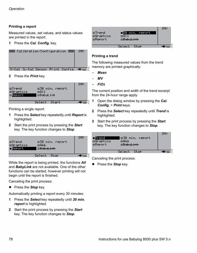
Operation
78 Instructions for use Babylog 8000 plus SW 5.n
Printing a report
Measured values, set values, and status values are printed in the report.
1 Press the Cal. Config. key.
2 Press the Print key.
Printing a single report:
1 Press the Select key repeatedly until Report is highlighted.
2 Start the print process by pressing the Start key. The key function changes to Stop.
While the report is being printed, the functions All and BabyLink are not available. One of the other functions can be started, however printing will not begin until the report is finished.
Canceling the print process:
Press the Stop key.
Automatically printing a report every 30 minutes:
1 Press the Select key repeatedly until 30 min. report is highlighted.
2 Start the print process by pressing the Start key. The key function changes to Stop.
Printing a trend
The following measured values from the trend memory are printed graphically:
– Mean
– MV
– FiO2
The current position and width of the trend excerpt from the 24-hour range apply.
1 Open the dialog window by pressing the Cal. Config. > Print keys.
2 Press the Select key repeatedly until Trend is highlighted.
3 Start the print process by pressing the Start key. The key function changes to Stop.
Canceling the print process:
Press the Stop key.
211
20
211
21
211
22
211
23
211
26
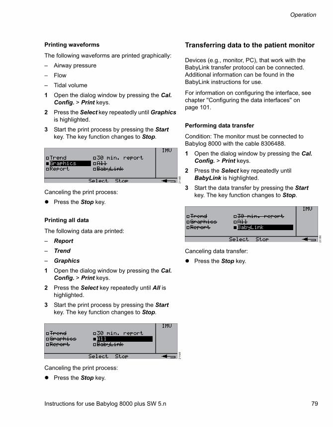
Instructions for use Babylog 8000 plus SW 5.n 79
Operation
Printing waveforms
The following waveforms are printed graphically:
– Airway pressure
– Flow
– Tidal volume
1 Open the dialog window by pressing the Cal. Config. > Print keys.
2 Press the Select key repeatedly until Graphics is highlighted.
3 Start the print process by pressing the Start key. The key function changes to Stop.
Canceling the print process:
Press the Stop key.
Printing all data
The following data are printed:
– Report
– Trend
– Graphics
1 Open the dialog window by pressing the Cal. Config. > Print keys.
2 Press the Select key repeatedly until All is highlighted.
3 Start the print process by pressing the Start key. The key function changes to Stop.
Canceling the print process:
Press the Stop key.
Transferring data to the patient monitor
Devices (e.g., monitor, PC), that work with the BabyLink transfer protocol can be connected. Additional information can be found in the BabyLink instructions for use.
For information on configuring the interface, see chapter ''Configuring the data interfaces'' on page 101.
Performing data transfer
Condition: The monitor must be connected to Babylog 8000 with the cable 8306488.
1 Open the dialog window by pressing the Cal. Config. > Print keys.
2 Press the Select key repeatedly until BabyLink is highlighted.
3 Start the data transfer by pressing the Start key. The key function changes to Stop.
Canceling data transfer:
Press the Stop key.
211
48
211
49
211
50

Operation
80 Instructions for use Babylog 8000 plus SW 5.n
Terminating operation
Switching the ventilator off
Condition: No patient must be connected to the device.
1 Move the protective flap (A) on the rear of the device to the side.
2 Press the mains switch (B) as far as it will go and then release it.
The device is switched off.
3 Unplug the mains plug.
4 Switch off the breathing gas humidifier and remove the mains plug.
Removing the compressed gas hoses
Disconnect the probes of the Air and O2 compressed gas hoses from the wall terminal units of the central gas supply system.
211
96
A
B
CAUTION
Contamination of the central gas supply system
Supply gases may flow back into the central gas supply system due to small leakages in the device or the compressed gas hoses.
After terminating operation, disconnect the compressed gas hoses from the central gas supply system.
CAUTION
Risk of personal injury
If the probes in the wall terminal units of the central gas supply system are connected, the compressed gas hoses are under pressure and may injure the user when unscrewing them from the ventilator.
The compressed gas hoses must only be unscrewed from the ventilator after the probes have been removed from the wall terminal units.

Instructions for use Babylog 8000 plus SW 5.n 81
Alarms
Alarms
Display of alarms........................................... 82
Optical alarm signals ....................................... 82Acoustic alarm signals..................................... 82Alarm priorities................................................. 82
Suppressing the acoustic alarm signal....... 83
Early reactivation of the alarm signal............... 83
Acknowledging alarm messages ................. 83
Alarm limits .................................................... 84
Automatic alarm limits ..................................... 84Manual alarm limits.......................................... 84Setting the alarm limits .................................... 84Deactivating alarm limits.................................. 85Response to power failure............................... 85

Alarms
82 Instructions for use Babylog 8000 plus SW 5.n
Display of alarms
Alarms are signaled optically and acoustically according to their alarm priority.
Optical alarm signals
The device displays the following optical alarm signals:
– The red LED flashes and the corresponding alarm message is displayed on the screen.
– Only in PSV ventilation mode:The yellow LED flashes in the following situations:
– The inspiratory time TI is not set correctly.
– The tidal volume Vtset cannot be applied.
Acoustic alarm signals
The alarm with the highest priority is signaled acoustically. The alarm signal sounds until either the cause of the alarm has been resolved or the alarm signal is suppressed.
The volume of the alarm signal can be regulated, see page 100.
Failure of the acoustic alarm signal
If the speaker for the alarm signal (main alarm) fails due to a fault, a continuous tone will be generated as an auxiliary alarm.
This continuous tone is also used for the power supply failure alarm.
Alarm priorities
The acoustic alarm signals indicate the priority of the active alarm. If multiple alarms occur simultaneously, the alarm message with the highest priority is displayed first.
For a list of causes and remedies, see chapter ''Alarm – Cause – Remedy'' on page 106.
Priority of the alarm message
Alarm signals Action required
Optical Acoustic
Warning Alarm with high priority
Red LED flashes
Continuous tones
Immediate action required to avert acute danger
Caution Alarm with medium priority
Red LED flashes
3 tones Quick action required to avert dan-ger
Note Alarm with low priority
- One tone Attention and action required

Instructions for use Babylog 8000 plus SW 5.n 83
Alarms
Suppressing the acoustic alarm signal
The acoustic alarm signal can be suppressed for a maximum of 2 minutes.
If another alarm occurs during this time, no alarm signal sounds. However, the alarm message is displayed on the screen.
If the fault triggering the alarm is not resolved after 2 minutes, the alarm signal sounds again.
Press the key.
The yellow LED on the key lights up.
Early reactivation of the alarm signal
Press the key.
The yellow LED on the key goes out.
Acknowledging alarm messages
After the fault triggering the alarm has been resolved, the alarm tone is silenced. High-priority alarm messages continue to be displayed and need to be acknowledged.
Press the OK key.

Alarms
84 Instructions for use Babylog 8000 plus SW 5.n
Alarm limits
Automatic alarm limits
The following alarm limits are set automatically and cannot be changed by the user:
– Airway pressure:
– Upper alarm limit for mechanical breaths
– Upper alarm limit for expiration or CPAP
– Lower alarm limit
– Alarm limit for disconnection
– O2 concentration:
– Upper alarm limit
– Lower alarm limit
Information on calculations can be found in chapter ''Monitoring functions'' on page 138.
Manual alarm limits
The following alarm limits must be set by the user:
Setting the alarm limits
1 Press the key.
The Alarm limits dialog window is opened.
2 Select the parameter by pressing the key.
3 Set the alarm limit using the or key.
Alarm limit Setting range
MV 0 to upper alarm limit
MV Lower alarm limit to 15 L/min
The alarm delay time Alarm delay delays the fol-lowing alarms:
0 to 30 seconds
– MV low
– VT low Check settings!
Apnea alarm time Apnoea time
5 to 20 seconds
Respiratory rate for panting breathing Panting
20 to 200 bpm
CAUTION
Risk of patient injury due to incorrect settings
If several identical or similar devices are being used in the care areas, the alarm limits of the devices may be configured differently and therefore not be appropriate for the current patient.– Check the alarm limits and adjust them to the
current patient and the required therapy.– Ensure that extreme or deactivated alarm
limits do not render the alarm system useless.
WARNING
Risk of patient injury
If the alarm limits are not adapted to the patient and the required therapy, the patient may be endangered.
Set the alarm limits accordingly.
21
06
7
Instructions for use Babylog 8000 plus SW 5.n 85
Alarms
Recommendations for setting MV alarm limits
Once the measured value for the minute volume MV has stabilized, the alarm limits can be calculated by the device:
– 30 % below the measured value MV for the lower alarm limit
– 30 % above the measured value MV for the upper alarm limit (max. 15 L/min)
Adopting the calculated alarm limits:
Press the ±30% key.
Deactivating alarm limits
The following alarm limits can be deactivated:
– When ventilating very small patients, apnea monitoring can be deactivated in order to avoid false alarms. Use a separate monitoring device for apnea.
– Respiratory rate for panting breathing
Deactivating the alarm limit Apnoea time
1 Select the alarm limit Apnoea time.
2 Set the value to >20 seconds.
The alarm limit is deactivated.
Deactivating the alarm limit Panting
1 Select the alarm limit Panting.
2 Set the value to <20 bpm.
The alarm limit is deactivated.
Response to power failure
Alarm limits are saved in the event of a power failure.
WARNING
Risk of patient injury
The device cannot monitor the patient if the alarm limits are deactivated.
Only deactivate alarm limits if the safety of the patient is not jeopardized by the absence of an alarm.
Trends
86 Instructions for use Babylog 8000 plus SW 5.n
Trends
Displaying waveforms and measured values ............................................................. 87
Displaying waveforms ..................................... 87Displaying measured values ........................... 87Displaying all set values and measured values........................................................................ 89
Displaying trends .......................................... 90
Displaying the logbook ................................. 91

Instructions for use Babylog 8000 plus SW 5.n 87
Trends
Displaying waveforms and measured values
Displaying waveforms
Displaying the airway pressure waveform Paw
1 On the main screen, press the Graph key.
2 Press the Paw key.
Displaying the flow waveform
1 On the main screen, press the Graph key.
2 Press the Flow key.
Freezing waveforms
1 On the main screen, press the Graph key.
2 Press the Stop key.
The waveform is immediately frozen.
Return to displaying the current waveform:
Press the Stop key.
Displaying measured values
Displaying the measured pressure values
1 On the main screen, press the Meas key.
2 Press the Paw key.
The following measured pressure values from the previous respiratory cycle are displayed (example):
21
07
0
A Pressure limitation Pinsp (dotted horizontal line)
B Pressure axis scale (e.g., 50 mbar (50 cmH2O))
C End of the set expiratory time TE (dotted verti-cal line)
D Time axis scale (e.g., 2 s)
21
07
1
E Flow axis scale (e.g., 10 L/min)
F Zero line
G End of the set expiratory time TE (dotted verti-cal line)
H Time axis scale (e.g., 2 s)
BA C D
E F G H
21
07
22
10
73
Peak Peak pressure
Mean Mean pressure
PEEP End-expiratory pressure

Trends
88 Instructions for use Babylog 8000 plus SW 5.n
Displaying lung-mechanics parameters
The patient's resistance and compliance are calculated using the linear-regression method. Information on calculations can be found on page 167.
After a manual inspiration, the display of waveforms is automatically stopped for one minute. The waveforms and associated measured values can be evaluated together.
1 On the main screen, press the Meas key.
2 Press the RC key.
Displaying measured volume values
1 On the main screen, press the Meas key.
2 Press the Vol key.
The following measured volume values are displayed (example):
Displaying combinations of measured values
1 On the main screen, press the Meas key.
2 Press the MV O2 P key.
The following measured values are displayed (example):
21
07
5
C Dynamic compliance of the respiratory system
R Airway resistance including the tube
C20/C Index indicating if the lungs are being overinflated. If C20/C <0.8 the lungs may be overinflated. Can only be used with ventilation modes without plateau.
Tc Time constant of the respiratory sys-tem in milliseconds
r Correlation coefficient of linear regres-sion
If the warning symbol (A) is displayed next to the value for r, the measured values may be distorted, e.g., due to a leakage.
A
21
07
6
MV Expiratory minute volume
spont Percentage of spontaneous breathing to minute volume
Leak Tube leakage
VT Expiratory tidal volume of the previous respiratory cycle
21
08
1
MV Expiratory minute volume
FiO2 Measured inspiratory O2 concentration
Mean Mean airway pressure of previous respiratory cycle
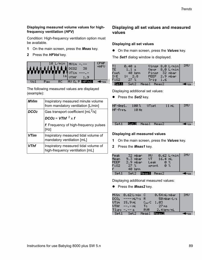
Instructions for use Babylog 8000 plus SW 5.n 89
Trends
Displaying measured volume values for high-frequency ventilation (HFV)
Condition: High-frequency ventilation option must be available.
1 On the main screen, press the Meas key.
2 Press the HFVol key.
The following measured values are displayed (example):
Displaying all set values and measured values
Displaying all set values
On the main screen, press the Values key.
The Set1 dialog window is displayed.
Displaying additional set values:
Press the Set2 key.
Displaying all measured values
1 On the main screen, press the Values key.
2 Press the Meas1 key.
Displaying additional measured values:
Press the Meas2 key.
21
08
3
MVim Inspiratory measured minute volume from mandatory ventilation [L/min]
DCO2 Gas transport coefficient [mL2/s]
DCO2 = VThf 2 x f
f: Frequency of high-frequency pulses [Hz]
VTim Inspiratory measured tidal volume of mandatory ventilation [mL]
VThf Inspiratory measured tidal volume of high-frequency ventilation [mL]
21
08
42
10
85
21
08
62
10
87

Trends
90 Instructions for use Babylog 8000 plus SW 5.n
Displaying trends
The progression of the following measured values over the past 24 hours is stored in the trend memory.
1 On the main screen, press the Trend key.
An segment of the trend memory is displayed. The starting time and length of the segment can be changed.
2 Select the desired measured value by pressing the Param key.
3 Use the and keys to select the length of the segment (max. 24 hours, min. 2 hours). The times displayed indicate the beginning and end of the segment.
4 Use the and keys to shift the segment:
FiO2 Inspiratory O2 concentration
Mean Mean pressure
MV Minute volume
C Dynamic compliance
R Resistance
RVR Ratio of respiratory rate to tidal volume
Indicator of chance of success upon weaning the patient from ventilation
211
11
211
12
A Located at the left end of the bar:The segment is located at the beginning of the trend memory.
211
13
B Located at the right end of the bar:The segment is located at the end of the trend memory.
A
B
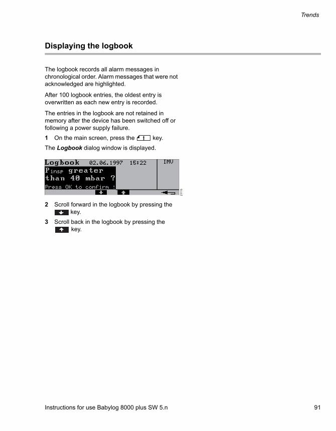
Instructions for use Babylog 8000 plus SW 5.n 91
Trends
Displaying the logbook
The logbook records all alarm messages in chronological order. Alarm messages that were not acknowledged are highlighted.
After 100 logbook entries, the oldest entry is overwritten as each new entry is recorded.
The entries in the logbook are not retained in memory after the device has been switched off or following a power supply failure.
1 On the main screen, press the key.
The Logbook dialog window is displayed.
2 Scroll forward in the logbook by pressing the key.
3 Scroll back in the logbook by pressing the key.
211
15
Monitoring
92 Instructions for use Babylog 8000 plus SW 5.n
Monitoring
Information on monitoring ........................... 93
Sensors and calibration intervals .................... 93
O2 monitoring ................................................ 94
Calibrating the O2 sensor ................................ 94
Flow monitoring ............................................ 95
Calibrating the flow sensor .............................. 95Deactivating and activating flow monitoring .... 96

Instructions for use Babylog 8000 plus SW 5.n 93
Monitoring
Information on monitoring
Sensors and calibration intervals
The device uses the following sensors for measurement and monitoring:
Recalibration is not necessary if the flow sensor has been unplugged only briefly.
Sensor Calibration
Pressure sen-sor
Automatic calibration
O2 sensor Automatic calibration every 24 hours
Manual calibration after replace-ment
Flow sensor Manual calibration:
– After switching on
– After reprocessing
– After replacement
CAUTION
Device function impaired
If the sensors are not calibrated, device function may be impaired.
Calibrate the sensors at the indicated intervals.
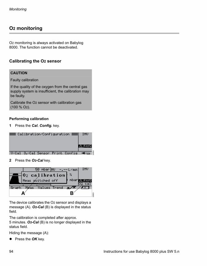
Monitoring
94 Instructions for use Babylog 8000 plus SW 5.n
O2 monitoring
O2 monitoring is always activated on Babylog 8000. The function cannot be deactivated.
Calibrating the O2 sensor
Performing calibration
1 Press the Cal. Config. key.
2 Press the O2-Cal key.
The device calibrates the O2 sensor and displays a message (A). O2-Cal (B) is displayed in the status field.
The calibration is completed after approx. 5 minutes. O2-Cal (B) is no longer displayed in the status field.
Hiding the message (A):
Press the OK key.
CAUTION
Faulty calibration
If the quality of the oxygen from the central gas supply system is insufficient, the calibration may be faulty.
Calibrate the O2 sensor with calibration gas (100 % O2).
20
95
02
09
53A B
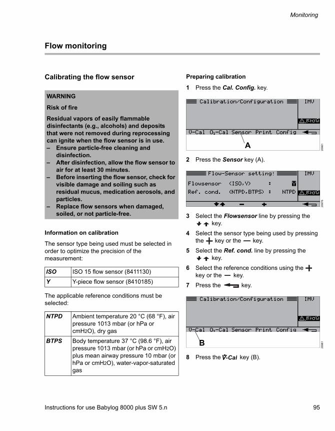
Instructions for use Babylog 8000 plus SW 5.n 95
Monitoring
Flow monitoring
Calibrating the flow sensor
Information on calibration
The sensor type being used must be selected in order to optimize the precision of the measurement:
The applicable reference conditions must be selected:
Preparing calibration
1 Press the Cal. Config. key.
2 Press the Sensor key (A).
3 Select the Flowsensor line by pressing the key.
4 Select the sensor type being used by pressing the key or the key.
5 Select the Ref. cond. line by pressing the key.
6 Select the reference conditions using the key or the key.
7 Press the key.
8 Press the key (B).
WARNING
Risk of fire
Residual vapors of easily flammable disinfectants (e.g., alcohols) and deposits that were not removed during reprocessing can ignite when the flow sensor is in use.– Ensure particle-free cleaning and
disinfection.– After disinfection, allow the flow sensor to
air for at least 30 minutes.– Before inserting the flow sensor, check for
visible damage and soiling such as residual mucus, medication aerosols, and particles.
– Replace flow sensors when damaged, soiled, or not particle-free.
ISO ISO 15 flow sensor (8411130)
Y Y-piece flow sensor (8410185)
NTPD Ambient temperature 20 °C (68 °F), air pressure 1013 mbar (or hPa or cmH2O), dry gas
BTPS Body temperature 37 °C (98.6 °F), air pressure 1013 mbar (or hPa or cmH2O) plus mean airway pressure 10 mbar (or hPa or cmH2O), water-vapor-saturated gas
20
96
12
09
76
20
96
1
A
B
-Cal

Monitoring
96 Instructions for use Babylog 8000 plus SW 5.n
Removing the flow sensor
1 Remove the tube connector.
2 Put on a sterile glove.
3 Seal the flow sensor. This ensures that the requirement for calibration (flow = 0) is met.
Performing calibration
Press the Start key.
The calibration is completed after approx. 1 second. A message is displayed on the screen.
After calibration
Connect the tube connector.
If calibration was not successful
Replace the flow sensor insert, see page 42.
Replace the flow sensor cable.
Deactivating and activating flow monitoring
20
91
82
09
96
21
02
8
WARNING
Risk of patient injury
The device cannot adequately monitor the patient if flow monitoring and volume monitoring are deactivated.
Provide appropriate substitute monitoring immediately.
WARNING
Risk of patient injury
No apnea monitoring takes place when flow monitoring is deactivated.
Use independent apnea monitoring.
CAUTION
Restricted ventilation functions
Patient-triggered ventilation is not possible if flow monitoring is deactivated.
Reactivate flow monitoring as soon as possible.
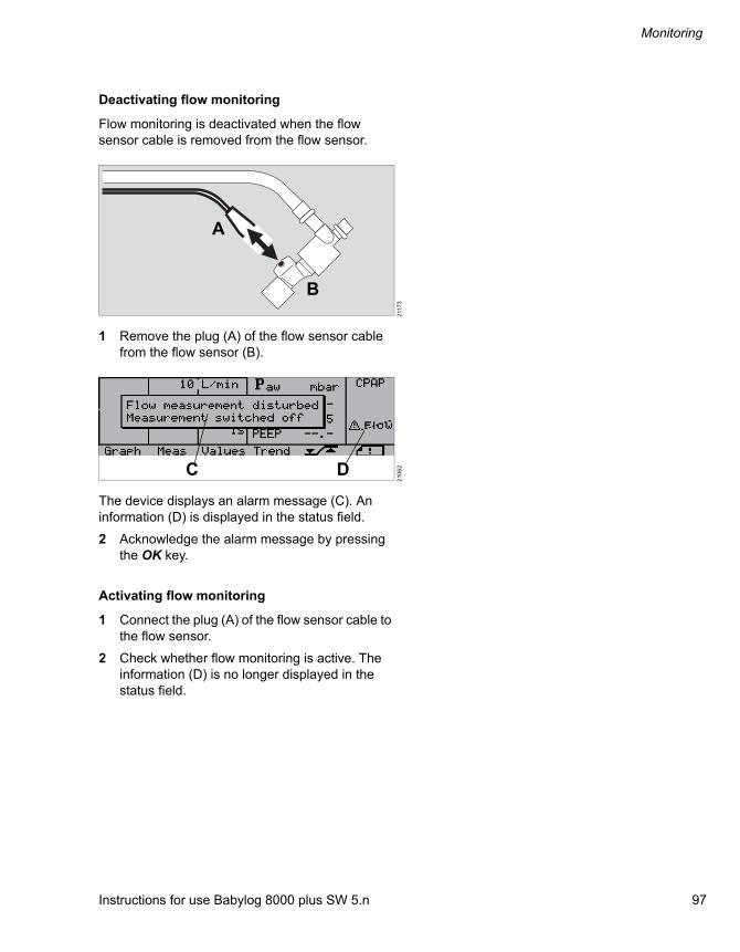
Instructions for use Babylog 8000 plus SW 5.n 97
Monitoring
Deactivating flow monitoring
Flow monitoring is deactivated when the flow sensor cable is removed from the flow sensor.
1 Remove the plug (A) of the flow sensor cable from the flow sensor (B).
The device displays an alarm message (C). An information (D) is displayed in the status field.
2 Acknowledge the alarm message by pressing the OK key.
Activating flow monitoring
1 Connect the plug (A) of the flow sensor cable to the flow sensor.
2 Check whether flow monitoring is active. The information (D) is no longer displayed in the status field.
211
73
21
06
2
A
B
C D

Configuration
98 Instructions for use Babylog 8000 plus SW 5.n
Configuration
Displaying device information ..................... 99
Setting date and time .................................... 99
Setting the volume of the alarm signal ....... 100
Setting the screen contrast .......................... 100
Selecting the language ................................. 101
Configuring the data interfaces ................... 101
Selecting the measuring signals and scale range for the analog output ports .................... 101Configuring the impulse output........................ 103Configuring the RS232 interface ..................... 104Configuring the printer..................................... 104

Instructions for use Babylog 8000 plus SW 5.n 99
Configuration
Displaying device information
Open the dialog window by pressing the Cal. Config. > Config keys.
The following device information is displayed:
– Software version
– Optional enhancements
– Operating hours
– Reference conditions for flow measurement and the sensor type being used
Setting date and time
This setting is saved after the device is switched off.
1 Open the dialog window by pressing the Cal. Config. > Config > Clock keys.
2 Use the and keys to select the appropriate parameter.
The selected parameter is highlighted.
3 Use the and keys to set the value.
20
93
82
111
6
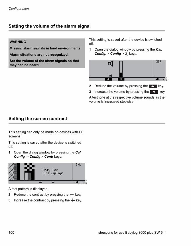
Configuration
100 Instructions for use Babylog 8000 plus SW 5.n
Setting the volume of the alarm signal
This setting is saved after the device is switched off.
1 Open the dialog window by pressing the Cal. Config. > Config > keys.
2 Reduce the volume by pressing the key.
3 Increase the volume by pressing the key.
A test tone at the respective volume sounds as the volume is increased stepwise.
Setting the screen contrast
This setting can only be made on devices with LC screens.
This setting is saved after the device is switched off.
1 Open the dialog window by pressing the Cal. Config. > Config > Contr keys.
A test pattern is displayed.
2 Reduce the contrast by pressing the key.
3 Increase the contrast by pressing the key.
WARNING
Missing alarm signals in loud environments
Alarm situations are not recognized.
Set the volume of the alarm signals so that they can be heard.
211
17
211
18

Instructions for use Babylog 8000 plus SW 5.n 101
Configuration
Selecting the language
The device is factory set to the customer's language.
1 Open the dialog window by pressing the Cal. Config. > Config > Lang keys.
The selected language is highlighted.
2 Use the and keys to select the language.
This setting is saved after the device is switched off.
Configuring the data interfaces
The following data interfaces can be configured:
– Analog output ports
– Impulse output
– RS232
This setting is saved after the device is switched off.
Selecting the measuring signals and scale range for the analog output ports
1 Open the dialog window by pressing the Cal. Config. > Config > Com keys.
2 Press the Param key repeatedly until Analog1 is highlighted.
3 Use the and keys to select the measuring signal.
4 Press the Param key.
5 Use the and keys to select the scale value.
Select the settings for Analog2 in the same way.
211
19
211
51
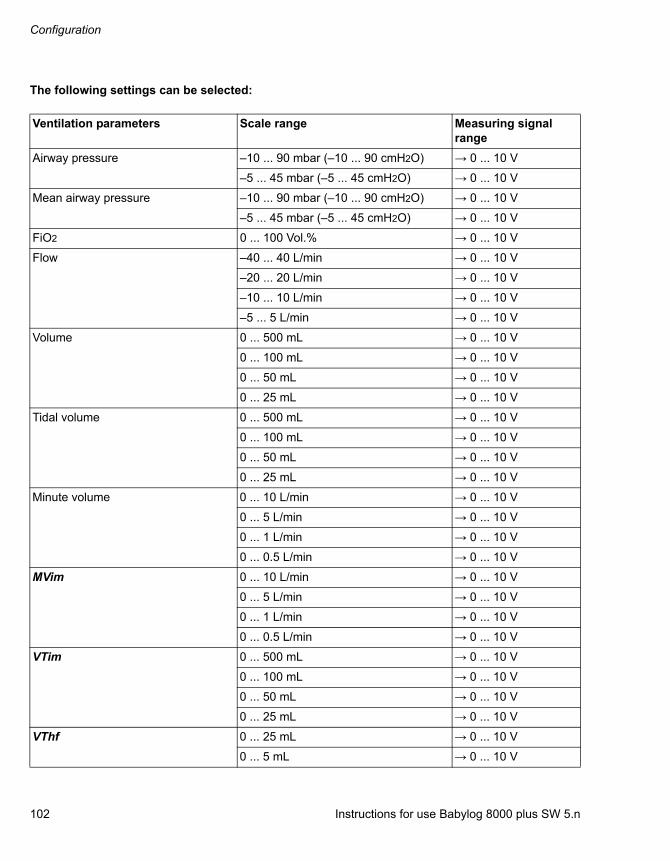
Configuration
102 Instructions for use Babylog 8000 plus SW 5.n
The following settings can be selected:
Ventilation parameters Scale range Measuring signal range
Airway pressure –10 ... 90 mbar (–10 ... 90 cmH2O) → 0 ... 10 V
–5 ... 45 mbar (–5 ... 45 cmH2O) → 0 ... 10 V
Mean airway pressure –10 ... 90 mbar (–10 ... 90 cmH2O) → 0 ... 10 V
–5 ... 45 mbar (–5 ... 45 cmH2O) → 0 ... 10 V
FiO2 0 ... 100 Vol.% → 0 ... 10 V
Flow –40 ... 40 L/min → 0 ... 10 V
–20 ... 20 L/min → 0 ... 10 V
–10 ... 10 L/min → 0 ... 10 V
–5 ... 5 L/min → 0 ... 10 V
Volume 0 ... 500 mL → 0 ... 10 V
0 ... 100 mL → 0 ... 10 V
0 ... 50 mL → 0 ... 10 V
0 ... 25 mL → 0 ... 10 V
Tidal volume 0 ... 500 mL → 0 ... 10 V
0 ... 100 mL → 0 ... 10 V
0 ... 50 mL → 0 ... 10 V
0 ... 25 mL → 0 ... 10 V
Minute volume 0 ... 10 L/min → 0 ... 10 V
0 ... 5 L/min → 0 ... 10 V
0 ... 1 L/min → 0 ... 10 V
0 ... 0.5 L/min → 0 ... 10 V
MVim 0 ... 10 L/min → 0 ... 10 V
0 ... 5 L/min → 0 ... 10 V
0 ... 1 L/min → 0 ... 10 V
0 ... 0.5 L/min → 0 ... 10 V
VTim 0 ... 500 mL → 0 ... 10 V
0 ... 100 mL → 0 ... 10 V
0 ... 50 mL → 0 ... 10 V
0 ... 25 mL → 0 ... 10 V
VThf 0 ... 25 mL → 0 ... 10 V
0 ... 5 mL → 0 ... 10 V

Instructions for use Babylog 8000 plus SW 5.n 103
Configuration
Setting the default values during operation
Press the key.
The default values are used.
If a measured value exceeds the limits of the scale, the voltage is limited to the maximum value on the scale.
Configuring the impulse output
The following signals are available:
– Triggered mandatory breath
– Mandatory breath
– Alarm
Default value: Mandatory breath
1 Open the dialog window by pressing the Cal. Config. > Config > Com keys.
2 Press the Param key repeatedly until is highlighted.
3 Use the or key to select the signal.
DCO2 0 ... 200 mL2/s → 0 ... 10 V
0 ... 50 mL2/s → 0 ... 10 V
Continuous flow (set value) 0 ... 125 L/min → 0 ... 10 V
Leakage rate 0 ... 100 % → 0 ... 10 V
Spontaneous portion of minute vol-ume
0 ... 100 % → 0 ... 10 V
Factory-set default values:
Analog1: Flow –20 ... 20 L/min
Analog2: Airway pressure –10 ... 90 mbar (–10 ... 90 cmH2O)
Ventilation parameters Scale range Measuring signal range
211
53
/P
211
54

Configuration
104 Instructions for use Babylog 8000 plus SW 5.n
Configuring the RS232 interface
The following settings can be made:
– Transfer speed Baudrate
– Parity test Parity
Factory-set default values:
1 Open the dialog window by pressing the Cal. Config. > Config > Com keys.
2 Press the Param key repeatedly until Baudrate is highlighted.
3 Use the or key to select one of the following values:
– 9600
– 2400
– 1200
4 Press the Param key repeatedly until Parity is highlighted.
5 Use the or key to select one of the following values:
– NONE
– EVEN
– ODD
When using the printer, select NONE.
Configuring the printer
The printer must be configured as follows:
Baudrate 9600
Parity NONE (no parity test)
Stop bit 1 (fixed)
Data bit 8 (fixed)
211
56
Baud rate As for Babylog 8000
Parity None
Data bit 8
Handshake mode
XON/XOFFAlternate Control Sequence Mode

Instructions for use Babylog 8000 plus SW 5.n 105
Troubleshooting
Troubleshooting
Failure of the power supply.......................... 106
Alarm – Cause – Remedy.............................. 106

Troubleshooting
106 Instructions for use Babylog 8000 plus SW 5.n
Failure of the power supply
If the power supply fails, the device triggers a power supply failure alarm. The ventilation settings and the alarm limits remain saved even in the event of a power supply failure.
Restore the power supply immediately, see page 50.
Or:
Disconnect the patient from the device and immediately resume ventilation using another, independent ventilator.
Alarm – Cause – Remedy
Alarm messages are displayed in a separate field in the current dialog window.
In the following table, the alarm messages are listed in alphabetical order. The table shows possible causes for an alarm and corresponding remedies. Causes and remedies must be worked through in the order listed until the alarm has been resolved.
Alarm message Cause Remedy
Airway pressure high Exp. valve opened
Increased pressure in the breath-ing circuit. The expiratory and emergency breathing valves have been opened to relieve pressure in the breathing circuit.
Check the breathing circuit and expiratory valve and replace if necessary.
Device malfunction. Contact DrägerService.
Airway pressure high Inspiration cancelled
Increased pressure in the breath-ing circuit. Mechanical inspiration has been shortened to relieve pressure in the system.
Check the breathing circuit and replace if necessary.
Device malfunction. Contact DrägerService.
Airway pressure low Leakage or disconnection Check the breathing circuit for leakages in the connections.
Inspiratory or expiratory flow set too low.
Increase flow.
Apnoea The patient's spontaneous breathing is interrupted.
Apply controlled ventilation.

Instructions for use Babylog 8000 plus SW 5.n 107
Troubleshooting
Calibrate flow sensor! The flow sensor must be cali-brated after the device is switched on and after a mains power supply failure.
Press the OK key and calibrate the flow sensor, see page 95.
The flow is not measured until the sensor has been calibrated.
To work without flow measure-ment, press only the OK key.
Check PEEP setting! The PEEP/CPAP setting knob determines the mean airway pressure during high-frequency ventilation.
After high-frequency ventilation is terminated, set PEEP to the desired value using the PEEP/CPAP setting knob.
Fault in rotary knob Device faulty. Contact DrägerService.
FiO2 high FiO2 measurement faulty. Calibrate O2 measurement man-ually, see page 94
Mixer function impaired. Contact DrägerService.
Air supply pressure too low. Ensure pressure greater than 2.7 bar (39.2 psi).
FiO2 low FiO2 measurement faulty. Calibrate O2 measurement man-ually, see page 94.
Mixer function impaired. Contact DrägerService.
O2 supply pressure too low. Ensure pressure greater than 2.7 bar (39.2 psi).
Flow measurement disturbed Measurement switched off
Flow sensor disconnected. Connect flow sensor or flow sen-sor cable. Calibrate the flow sen-sor, see page 95.
Flow sensor faulty. Replace the flow sensor, see page 42.
Flow sensor cable faulty. Replace the flow sensor cable.
Flow measurement disturbed VG uses Pinsp, Check set value!
Volume regulation VG inter-rupted because the flow sensor is faulty or disconnected. Flow measurement fault.
Replace flow sensor.Connect flow sensor cable.Set Pinsp to an appropriate setting.
Flow sensor dirty? Please clean sensor!
Water or secretion in the flow sensor.
Replace the flow sensor insert.
Flow sensor cable faulty. Replace the flow sensor cable.
Frequency high! Hyperventilation Set respiratory rate.
Auto-triggering Increase trigger threshold.
Hose kinked? Breathing hose kinked, blocked, or condensate in breathing hose.
Check breathing hoses, establish clear passage.
Inner diameter of breathing hoses too small.
Use a suitable breathing circuit.
Alarm message Cause Remedy

Troubleshooting
108 Instructions for use Babylog 8000 plus SW 5.n
I : E maximum 3 : 1! The setting knobs for TI and TE have been used to set a TI:TE ratio greater than 3:1. The setting is limited to 3:1.
Check setting of TI and TE and adjust if necessary.
IRV! The setting knobs for TI and TE have been used to set a TI:TE ratio greater than 1:1 (inverse ratio ventilation).
Press the OK key or check the settings for TI and TE and adjust if necessary.
Leak in hose system? Check setting!
Leakage or disconnection. Check the breathing circuit for leaks.
The set value for Pinsp is too high.
Check the set value for Pinsp.
Loss of stored data Device malfunction, e.g., after a power supply failure.
Reset lost set values or contact DrägerService.
Machine fault xyz
xyz: error code
Device malfunction. Contact DrägerService.
Medical air low Air supply pressure too low. Ensure pressure greater than 2.7 bar (39.2 psi).
Medical air supply pressure measurement disturbed
Pressure sensor or pressure reducer faulty.
Contact DrägerService.
MV high Lung compliance has increased. Resistance has decreased. Hyperventilation.
Check ventilation settings and adjust if necessary.
Device malfunction. Contact DrägerService.
MV low Lung compliance has decreased. Resistance has increased. Spon-taneous breathing intermittent or weaker.
Check ventilation settings and adjust if necessary.
Tube leakage too high Check that the tube is connected correctly.
Device malfunction. Contact DrägerService.
O2 calibration Meas switched off
The device is calibrating the O2 sensor.
Press the OK key.
O2 calibration disturbed An error occurred during calibra-tion.
Recalibrate manually, see page 94.Contact DrägerService.
O2 measurement disturbed Change sensor!
O2 sensor is spent. Insert a new O2 sensor, see page 42.
O2 measurement disturbed? FiO2 measurement impaired. Replace the O2 sensor, see page 42.Contact DrägerService.
O2 pressure low O2 supply pressure too low. Ensure pressure greater than 2.7 bar (39.2 psi).
Alarm message Cause Remedy
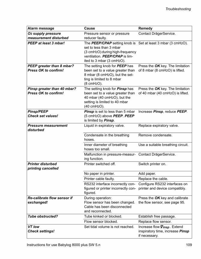
Instructions for use Babylog 8000 plus SW 5.n 109
Troubleshooting
O2 supply pressure measurement disturbed
Pressure sensor or pressure reducer faulty.
Contact DrägerService.
PEEP at least 3 mbar! The PEEP/CPAP setting knob is set to less than 3 mbar (3 cmH2O) during high-frequency ventilation. PEEP/CPAP is lim-ited to 3 mbar (3 cmH2O).
Set at least 3 mbar (3 cmH2O).
PEEP greater than 8 mbar? Press OK to confirm!
The setting knob for PEEP has been set to a value greater than 8 mbar (8 cmH2O), but the set-ting is limited to 8 mbar (8 cmH2O).
Press the OK key. The limitation of 8 mbar (8 cmH2O) is lifted.
Pinsp greater than 40 mbar? Press OK to confirm!
The setting knob for Pinsp has been set to a value greater than 40 mbar (40 cmH2O), but the setting is limited to 40 mbar (40 cmH2O).
Press the OK key. The limitation of 40 mbar (40 cmH2O) is lifted.
Pinsp/PEEP Check set values!
Pinsp is set to less than 5 mbar (5 cmH2O) above PEEP. PEEP is limited by Pinsp.
Increase Pinsp, reduce PEEP.
Pressure measurement disturbed
Liquid in expiratory valve. Replace expiratory valve.
Condensate in the breathing hoses.
Remove condensate.
Inner diameter of breathing hoses too small.
Use a suitable breathing circuit.
Malfunction in pressure-measur-ing function.
Contact DrägerService.
Printer disturbed printing cancelled
Printer switched off. Switch printer on.
No paper in printer. Add paper.
Printer cable faulty. Replace the cable.
RS232 interface incorrectly con-figured or printer incorrectly con-figured.
Configure RS232 interfaces on printer and device compatibly.
Re-calibrate flow sensor if exchanged!
During operation:Flow sensor has been changed. Cable has been disconnected and reconnected.
Press the OK key and calibrate the flow sensor, see page 95.
Tube obstructed? Tube kinked or blocked. Establish free passage.
Flow sensor blocked. Replace flow sensor.
VT low Check settings!
Set tidal volume is not reached. Increase flow . Extend inspiratory time, increase Pinsp if necessary.
Alarm message Cause Remedy
insp

Cleaning, disinfection and sterilization
110 Instructions for use Babylog 8000 plus SW 5.n
Cleaning, disinfection and sterilization
Safety information ......................................... 111
Dismantling the ventilator ............................ 111
Before dismantling........................................... 111Dismantling the Y-piece and flow sensor ........ 112Dismantling the pneumatic medication nebulizer.......................................................... 112Disconnecting the breathing hoses ................. 113Removing the expiratory valve ........................ 113Dismantling the accessories............................ 113
Reprocessing methods................................. 114
Classification of medical devices..................... 114Testing of methods and agents ....................... 114Non-critical medical devices............................ 114Semi-critical medical devices .......................... 115Visual inspection ............................................. 116Sterilization...................................................... 116
Reprocessing list .......................................... 117
Non-critical medical devices............................ 117Semi-critical medical devices .......................... 117Manual reprocessing of the Y-piece................ 118
After reprocessing ........................................ 119
Assembling the components ........................... 119Preparation for next use .................................. 119

Instructions for use Babylog 8000 plus SW 5.n 111
Cleaning, disinfection and sterilization
Safety information
Observe the hygiene regulations of the hospital.
Reprocess the device after every patient.
The components filled with contaminated gas during normal operation and the first fault must be reprocessed.
During normal operation the expiratory valve, along with the ejector and muffler, are filled with contaminated gas.
Using an inspiratory bacterial filter prevents contaminated gas from reaching the device via the inspiratory side in the event of device failure.
Dismantling the ventilator
This chapter describes how to disconnect the contaminated ventilation accessories and dismantle them for reprocessing.
Before dismantling
1 Switch off the device and breathing gas humidifier and unplug their mains plugs.
2 Empty the water traps and breathing hoses.
3 Empty the water container of the breathing gas humidifier.
CAUTION
Risk of infection
If reusable medical devices are not reprocessed, there is an increased risk of infection to both hospital staff and patients.– Clean and disinfect reusable medical devices
after each use.– Protective clothing, eye protection etc. must
be worn.
CAUTION
Health hazard
Ethylene oxide may diffuse into items during sterilization.
Do not sterilize items in ethylene oxide.
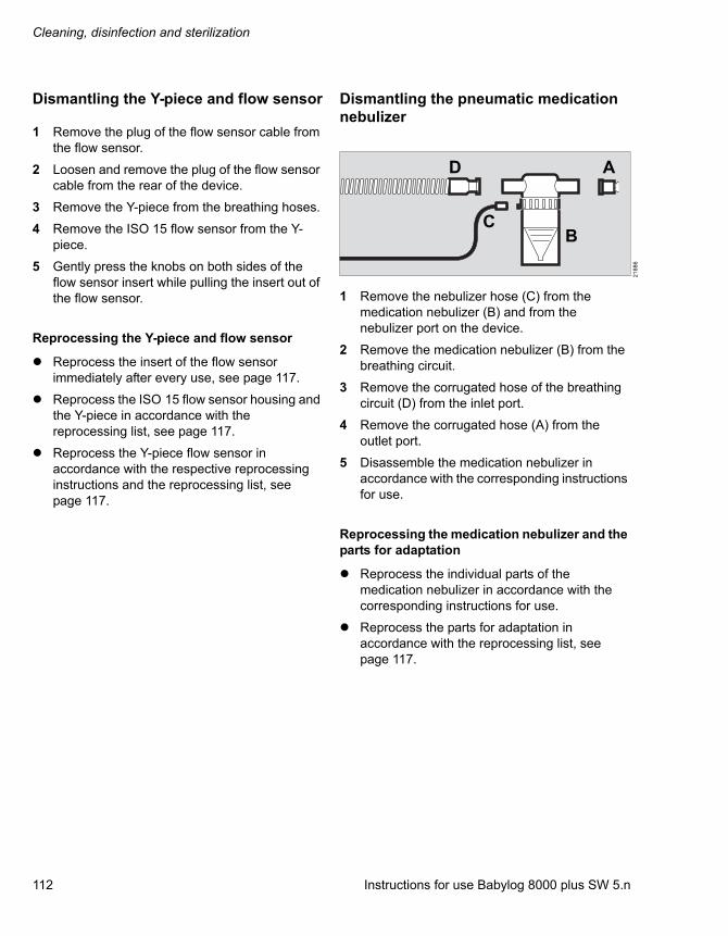
Cleaning, disinfection and sterilization
112 Instructions for use Babylog 8000 plus SW 5.n
Dismantling the Y-piece and flow sensor
1 Remove the plug of the flow sensor cable from the flow sensor.
2 Loosen and remove the plug of the flow sensor cable from the rear of the device.
3 Remove the Y-piece from the breathing hoses.
4 Remove the ISO 15 flow sensor from the Y-piece.
5 Gently press the knobs on both sides of the flow sensor insert while pulling the insert out of the flow sensor.
Reprocessing the Y-piece and flow sensor
Reprocess the insert of the flow sensor immediately after every use, see page 117.
Reprocess the ISO 15 flow sensor housing and the Y-piece in accordance with the reprocessing list, see page 117.
Reprocess the Y-piece flow sensor in accordance with the respective reprocessing instructions and the reprocessing list, see page 117.
Dismantling the pneumatic medication nebulizer
1 Remove the nebulizer hose (C) from the medication nebulizer (B) and from the nebulizer port on the device.
2 Remove the medication nebulizer (B) from the breathing circuit.
3 Remove the corrugated hose of the breathing circuit (D) from the inlet port.
4 Remove the corrugated hose (A) from the outlet port.
5 Disassemble the medication nebulizer in accordance with the corresponding instructions for use.
Reprocessing the medication nebulizer and the parts for adaptation
Reprocess the individual parts of the medication nebulizer in accordance with the corresponding instructions for use.
Reprocess the parts for adaptation in accordance with the reprocessing list, see page 117.
21
88
6
CB
AD

Instructions for use Babylog 8000 plus SW 5.n 113
Cleaning, disinfection and sterilization
Disconnecting the breathing hoses
1 Remove the breathing hoses from the inspiratory port and the expiratory port.
2 If in use: remove the water trap from the breathing hose.
3 Remove the water trap container from the water trap and empty it.
4 Remove the bacterial filter and dispose of it in accordance with the corresponding instructions for use.
Reprocessing the breathing circuit
Reprocess the breathing hoses, the water trap, and the water trap container in accordance with the reprocessing list, see page 117.
Removing the expiratory valve
1 Tilt the rocker lever (A) up.
2 Pull the expiratory valve forward to remove it.
3 Remove the muffler from the expiratory valve.
Reprocessing the expiratory valve
Reprocess the expiratory valve and muffler in accordance with the reprocessing list, see page 117.
Dismantling the accessories
Dismantle and reprocess the breathing gas humidifier and the Aeroneb Pro nebulizer in accordance with the corresponding instructions for use.
Dismantle and dispose of the bacterial filter in accordance with the corresponding instructions for use.
CAUTION
Damage to the breathing hoses
When removing the breathing hoses, hold them at the connection sleeve and not at the coil reinforcement.
211
97
A

Cleaning, disinfection and sterilization
114 Instructions for use Babylog 8000 plus SW 5.n
Reprocessing methods
Classification of medical devices
For reprocessing, the medical devices and their components are classified according to their type of application and the resulting risks:
– Non-critical medical devices: Surfaces accessible to the user and patient, e.g., device surfaces, cables
– Semi-critical medical devices: parts conducting breathing gas, e.g., breathing hoses, masks
Testing of methods and agents
Cleaning, disinfection, and sterilization of medical devices has been tested with the following procedures and agents. At the time of testing, the following procedures and agents showed good material compatibility and effectiveness:
Non-critical medical devices
Manual disinfection and simultaneous cleaning:
– Buraton 10F by Schülke & Mayr
– Concentration: 0.5 %, contact time: 60 min
– Concentration: 1 %, contact time: 30 min
Semi-critical medical devices
Manual cleaning:
– Neodisher LM2 by Dr. Weigert
– Sekusept powder classic by ECOLAB (Y-piece flow sensor)
Manual disinfection:
– Korsolex extra by Bode Chemie
– Concentration: 3 %, contact time: 15 min
Machine cleaning:
– Neodisher MediClean by Dr. Weigert
Machine disinfection:
– Thermal, 93 °C (199.4 °F) for 10 min
Sterilization:
– Hot steam, 134 °C (273.2 °F) for 5 min
Non-critical medical devices
Manual disinfection with simultaneous cleaning
When selecting a suitable disinfectant, adhere to the country-specific lists of disinfectants. The list of the German Association for Applied Hygiene (Verbund für Angewandte Hygiene VAH) applies in German-speaking countries.Strictly observe the manufacturer's specifications on the disinfectants. Manufacturers may change the composition of disinfectants over time.
Procedures:
1 Remove soiling immediately with a cloth soaked in disinfectant.
2 Perform surface disinfection by scrubbing and wiping.
3 Remove disinfectant residues after the contact time has elapsed.
WARNING
Risk of electric shock or device malfunction
Liquid that enters into the device can cause the device to malfunction or may damage the device and endanger the patient.
Only scrub-and-wipe-disinfect device surfaces and cables and make sure no liquids penetrate into the device.

Instructions for use Babylog 8000 plus SW 5.n 115
Cleaning, disinfection and sterilization
Semi-critical medical devices
Manual cleaning
Perform manual cleaning preferably under flowing water and with commercially available cleaning agent (pH value ≤ 12).
Procedures:
1 Wash off surface soiling under flowing water.
2 Use cleaning agents in accordance with manufacturer’s specifications. Make sure that all surfaces and interior spaces to be cleaned can be reached. Use suitable brushes if necessary.
3 Thoroughly rinse components under running water until cleaning agent residues are no longer discernible.
4 Inspect components for visible soiling and damage. Repeat manual cleaning if necessary.
Manual disinfection
When selecting a suitable disinfectant, adhere to the country-specific lists of disinfectants. The list of the German Association for Applied Hygiene (Verbund für Angewandte Hygiene VAH) applies in German-speaking countries.
Strictly observe the manufacturer's specifications on the disinfectants. Manufacturers may change the composition of disinfectants over time.
Procedures:
1 Disinfect components by immersing.
2 After the contact time has elapsed, rinse the components thoroughly under running water until disinfectant residues are no longer discernible.
3 Inspect components for visible soiling and damage. Repeat manual disinfection if necessary.
4 Shake off all excess water. Allow components to dry thoroughly.
Machine cleaning and disinfection
Perform machine cleaning and disinfection with a washer-disinfector in accordance with EN ISO 15883, preferably with a cart for anesthesia accessories and ventilation accessories.
Procedures:
1 Strictly observe the instructions for use of the washer-disinfector.
2 Position the parts in the basket in a stable position. Make sure that all interior spaces and surfaces are completely flushed and water can drain off freely.
3 Use a suitable cleaning agent.
4 Select a suitable program, preferably anesthesia program.
– Cleaning must be performed at 40 °C to 60 °C (104 °F to 140 °F) for at least 5 minutes.
– Thermal disinfection must be performed at 80 °C to 95 °C (176 °F to 203 °F) and with corresponding contact time.
5 Carry out final rinsing with demineralized water.
6 Immediately remove the components from washer-disinfector.
7 Inspect components for visible soiling and damage. If necessary, repeat the program or perform manual cleaning or manual disinfection.
8 Allow components to dry thoroughly.
Cleaning, disinfection and sterilization
116 Instructions for use Babylog 8000 plus SW 5.n
Visual inspection
Check all items for damage and external signs of wear, such as cracking, embrittlement, or pronounced hardening, and residual dirt.
Sterilization
Sterilization eliminates living microorganisms from semicritical medical devices and dries residual water in the interior of components.
Sterilize only components that have been cleaned and disinfected.
For sterilization, use a vacuum steam sterilizer (in accordance with DIN EN 285), preferably with fractional vacuum.
CAUTION
Risk due to faulty accessories
Even reusable accessories have a limited service life, e.g., disinfectant residues can corrode the material during autoclaving. External signs of wear can occur, e.g., cracks, deformations, discolorations, or peeling.
If there are external signs of wear, exchange affected accessories.
NOTE
The service life of the breathing circuit "HF Fisher & Paykel" (8411153) may be shorter than the service life of the breathing circuit (8411041).
The ventilation hoses must be replaced if cracks are present or the spiral ribbing is detached.
In the case of discoloration, which may occur following frequent reprocessing, replacement is not necessary.
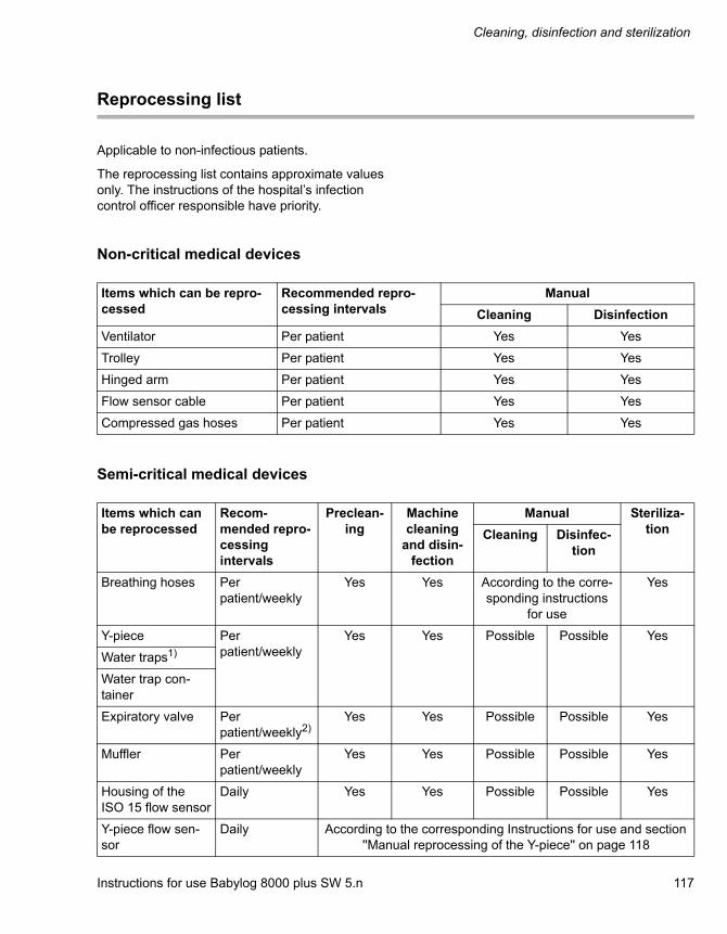
Instructions for use Babylog 8000 plus SW 5.n 117
Cleaning, disinfection and sterilization
Reprocessing list
Applicable to non-infectious patients.
The reprocessing list contains approximate values only. The instructions of the hospital’s infection control officer responsible have priority.
Non-critical medical devices
Semi-critical medical devices
Items which can be repro-cessed
Recommended repro-cessing intervals
Manual
Cleaning Disinfection
Ventilator Per patient Yes Yes
Trolley Per patient Yes Yes
Hinged arm Per patient Yes Yes
Flow sensor cable Per patient Yes Yes
Compressed gas hoses Per patient Yes Yes
Items which can be reprocessed
Recom-mended repro-cessing intervals
Preclean-ing
Machine cleaning
and disin-fection
Manual Steriliza-tionCleaning Disinfec-
tion
Breathing hoses Per patient/weekly
Yes Yes According to the corre-sponding instructions
for use
Yes
Y-piece Per patient/weekly
Yes Yes Possible Possible Yes
Water traps1)
Water trap con-tainer
Expiratory valve Per patient/weekly2)
Yes Yes Possible Possible Yes
Muffler Per patient/weekly
Yes Yes Possible Possible Yes
Housing of the ISO 15 flow sensor
Daily Yes Yes Possible Possible Yes
Y-piece flow sen-sor
Daily According to the corresponding Instructions for use and section ''Manual reprocessing of the Y-piece'' on page 118
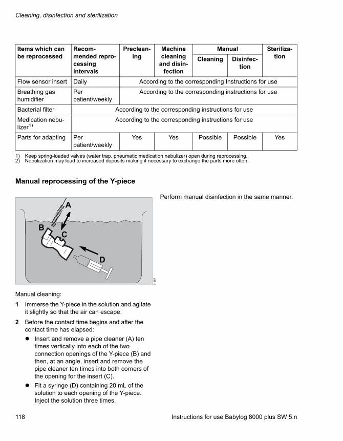
Cleaning, disinfection and sterilization
118 Instructions for use Babylog 8000 plus SW 5.n
Manual reprocessing of the Y-piece
Manual cleaning:
1 Immerse the Y-piece in the solution and agitate it slightly so that the air can escape.
2 Before the contact time begins and after the contact time has elapsed:
Insert and remove a pipe cleaner (A) ten times vertically into each of the two connection openings of the Y-piece (B) and then, at an angle, insert and remove the pipe cleaner ten times into both corners of the opening for the insert (C).
Fit a syringe (D) containing 20 mL of the solution to each opening of the Y-piece. Inject the solution three times.
Perform manual disinfection in the same manner.
Flow sensor insert Daily According to the corresponding Instructions for use
Breathing gas humidifier
Per patient/weekly
According to the corresponding instructions for use
Bacterial filter According to the corresponding instructions for use
Medication nebu-lizer1)
According to the corresponding instructions for use
Parts for adapting Per patient/weekly
Yes Yes Possible Possible Yes
1) Keep spring-loaded valves (water trap, pneumatic medication nebulizer) open during reprocessing.2) Nebulization may lead to increased deposits making it necessary to exchange the parts more often.
Items which can be reprocessed
Recom-mended repro-cessing intervals
Preclean-ing
Machine cleaning
and disin-fection
Manual Steriliza-tionCleaning Disinfec-
tion
21
88
7
A
BC
D
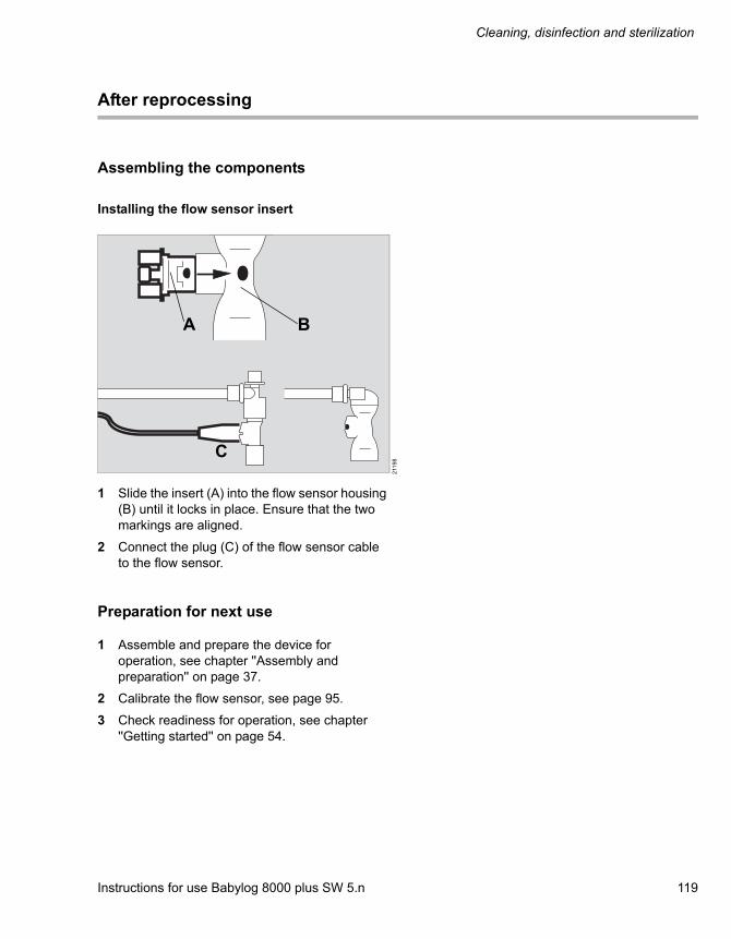
Instructions for use Babylog 8000 plus SW 5.n 119
Cleaning, disinfection and sterilization
After reprocessing
Assembling the components
Installing the flow sensor insert
1 Slide the insert (A) into the flow sensor housing (B) until it locks in place. Ensure that the two markings are aligned.
2 Connect the plug (C) of the flow sensor cable to the flow sensor.
Preparation for next use
1 Assemble and prepare the device for operation, see chapter ''Assembly and preparation'' on page 37.
2 Calibrate the flow sensor, see page 95.
3 Check readiness for operation, see chapter ''Getting started'' on page 54.
211
98
A B
C

Maintenance
120 Instructions for use Babylog 8000 plus SW 5.n
Maintenance
Overview ........................................................ 121
Inspection ...................................................... 122
Safety checks .................................................. 122
Preventive maintenance ............................... 124
Table of preventive maintenance intervals...... 124
Repairs ........................................................... 125
Replacing the cooling air filter ..................... 126

Instructions for use Babylog 8000 plus SW 5.n 121
Maintenance
Overview
This chapter describes the necessary maintenance measures required to maintain the proper functioning of the medical device. Maintenance measures must be performed by the personnel responsible.
Definition of maintenance concepts
WARNING
Risk of infection
The responsible personnel may be infected by pathogenic germs.
Disinfect and clean device or device parts before any maintenance measures and also before returning the medical device for repair.
WARNING
Risk of electric shock
There are conducting components under the housing cover.– Do not remove the housing cover.– Maintenance measures must be
performed by the personnel responsible. Dräger recommends DrägerService for repairs and complex maintenance tasks.
CAUTION
Malfunction
Soiled cooling air filters can compromise proper operation of the device.
Replace the cooling air filters at regular intervals.
Concept Definition
Maintenance All measures (inspection, preventive maintenance, repair) intended to maintain and restore the functional condition of a medical device
Inspection Measures intended to determine and assess the actual state of a medical device
Preventive mainte-nance
Recurrent specified measures intended to maintain the functional condition of a medical device
Repair Measures intended to restore the functional condition of a medical device after a device malfunction

Maintenance
122 Instructions for use Babylog 8000 plus SW 5.n
Inspection
Perform inspections at regular intervals and observe the following specifications.
Safety checks
The safety checks are no substitute for the preventive maintenance measures (including preventive replacement of wear parts) indicated by the manufacturer.
1 Check accompanying documents:
– Instructions for use are available
2 Check that the device combination is in good condition:
– All labels are complete and legible
– No visible damage to the following parts:
– Trolley and brakes
– Housing parts
– Gas inlets
– Hoses and cables
– Fuses which are accessible from the outside are in compliance with the specified values
– Country-specific labeling of gas types
3 Using the instructions for use, check that all components and accessories needed to use the product are available.
4 Check safety features:
– Correct functioning of the emergency breathing valve:Before the check, switch off the device. Pressure: max. –4 mbar (or hPa or cmH2O)
Checks Interval Personnel responsible
Inspection and safety checks1)
1) Designation applies to the Federal Republic of Germany; corresponds to the “Recurring safety inspection” in the Republic of Austria
Every 6 months Service personnel
CAUTION
Risk of medical device failure
If safety checks are not performed on a regular basis, the proper operation of the medical device can be compromised.
Perform safety checks at the indicated intervals.
22
60
9

Instructions for use Babylog 8000 plus SW 5.n 123
Maintenance
– Correct functioning of the pneumatic safety valve:Before the check, switch off the device and unplug the mains plug.Pressure: 90 to 110 mbar (or hPa or cmH2O)
5 Check the electrical safety according to IEC 62353. If a breathing gas humidifier or power socket strip (e.g., on the trolley) are used, they must be subjected to the same check. The check must be performed on individual devices and in the integrated system.
– Protective ground contact resistance <0.3
– Replacement device leakage current <1 mA
– Replacement patient leakage current <5 mA
6 Perform a functional test of the following features according to the instructions for use:
– All functions described in the test steps of the device check.
– Functioning of the power supply failure alarm
22
61
0
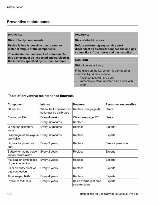
Maintenance
124 Instructions for use Babylog 8000 plus SW 5.n
Preventive maintenance
Table of preventive maintenance intervals
WARNING
Risk of faulty components
Device failure is possible due to wear or material fatigue of the components.
To maintain the function of all components, this device must be inspected and serviced at the intervals specified by the manufacturer.
WARNING
Risk of electric shock
Before performing any service work, disconnect all electrical connections and gas connections from power and gas supplies.
CAUTION
Risk of personal injury
If the glass on the LC screen is damaged, a chemical liquid may escape.– Avoid contact with the body.– Immediately clean affected skin areas with
soap.
Component Interval Measure Personnel responsible
O2 sensor When the O2 sensor can no longer be calibrated
Replace, see page 42 Users
Cooling air filter Every 4 weeks Clean, see page 126 Users
Every 12 months Replace
O-ring for expiratory valve
Every 12 months Replace Experts
Diaphragm of the expira-tory valve
Every 12 months Replace Experts
Lip seal for pneumatic part
Every 2 years Replace Service personnel
Battery for mains power supply failure alarm
Every 2 years Replace Experts
Flat seal on entry block of gas connection
Every 2 years Replace Experts
Filter on entry block of gas connection
Every 2 years Replace Experts
Time keeper RAM Every 4 years Replace Experts
Pressure reducers Every 6 years Basic overhaul of pres-sure reducers
Experts

Instructions for use Babylog 8000 plus SW 5.n 125
Maintenance
Repairs
Dräger recommends that all repairs are carried out by DrägerService and that only authentic Dräger repair parts are used.
O-rings for pressure reducer
Every 6 years Replace Experts
O-rings for inspiratory block
Every 6 years Replace Experts
Micro switch for pneu-matic valve
Every 6 years Replace Experts
Washer for safety valve Every 6 years Replace Experts
Diaphragm for safety valve
Every 6 years Replace Experts
Integrated diaphragm for O2 equalization valve
Every 6 years Replace Experts
Component Interval Measure Personnel responsible

Maintenance
126 Instructions for use Babylog 8000 plus SW 5.n
Replacing the cooling air filter
1 Pull the cooling air filter (A) out of the holder in the rear panel.
2 Replace the cooling air filter or clean it in warm soapy water and dry thoroughly.
3 Insert the cooling air filter in the holder in the rear panel.
21
21
2
A

Instructions for use Babylog 8000 plus SW 5.n 127
Disposal
Disposal
Disposal of the medical device .................... 128
For countries subject to the EU Directive 2002/96/EC...................................................... 128
Disposal of batteries ..................................... 128
Disposal of O2 sensors ................................. 129

Disposal
128 Instructions for use Babylog 8000 plus SW 5.n
Disposal of the medical device
At the end of its service life:
Have the medical device appropriately disposed of in accordance with applicable laws and regulations.
For countries subject to the EU Directive 2002/96/EC
This device is subject to EU Directive 2002/96/EC (WEEE). In order to comply with its registration according to this directive, this device may not be disposed of at municipal collection points for waste electrical and electronic equipment. Dräger has authorized a company to collect and dispose of this device. To initiate collection or for further information, visit Dräger on the Internet at www.draeger.com. Use the search function with the keyword "WEEE" to find the relevant information. If access to the Dräger website is not possible, contact the local Dräger organization.
Disposal of batteries
The medical device battery contains pollutant substances.
For the Federal Republic of Germany: The user is obliged by law to return batteries which contain toxic substances either to the manufacturer/distributor or to a collection center operated by public waste disposal corporations. The battery installed in the device must therefore be removed by experts before disposal of the device. Observe the applicable laws and regulations for battery disposal.
CAUTION
Risk of infection
Disinfect and clean the device before disposal.
WARNING
Risk of explosion and of chemical burns
Improper handling of batteries can result in explosions and chemical burns.– Do not throw batteries into fire.– Do not force batteries open.

Instructions for use Babylog 8000 plus SW 5.n 129
Disposal
Disposal of O2 sensors
O2 sensors can be sent back to Dräger.
WARNING
Risk of explosion and of chemical burns
Improper handling of O2 sensors can result in explosions and chemical burns.– Do not throw O2 sensors into fire.– Do not force O2 sensors open.
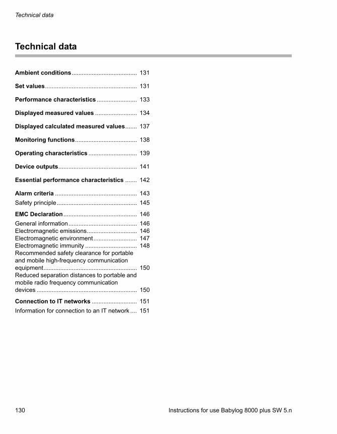
Technical data
130 Instructions for use Babylog 8000 plus SW 5.n
Technical data
Ambient conditions ....................................... 131
Set values....................................................... 131
Performance characteristics ........................ 133
Displayed measured values ......................... 134
Displayed calculated measured values....... 137
Monitoring functions..................................... 138
Operating characteristics ............................. 139
Device outputs............................................... 141
Essential performance characteristics ....... 142
Alarm criteria ................................................. 143
Safety principle................................................ 145
EMC Declaration ............................................ 146
General information......................................... 146Electromagnetic emissions.............................. 146Electromagnetic environment.......................... 147Electromagnetic immunity ............................... 148Recommended safety clearance for portable and mobile high-frequency communication equipment........................................................ 150Reduced separation distances to portable and mobile radio frequency communication devices ............................................................ 150
Connection to IT networks ........................... 151
Information for connection to an IT network .... 151

Instructions for use Babylog 8000 plus SW 5.n 131
Technical data
Ambient conditions
Set values
During operation
Temperature 10 to 40 °C(50 to 104 °F)
Pressure range 780 to 1060 hPa(11.3 to 15.4 psi)
Relative humidity 30 % to 90 %, without condensation
During storage and transportation
Temperature –20 °C to 60 °C(–4 °F to 140 °F)
Pressure range 500 to 1060 hPa(7.3 to 15.4 psi)
Relative humidity 10 % to 95 %, without condensation
Depending on the accessories used, more stringent ambient conditions can apply. Strictly observe the corresponding instructions for use.
Unless explicitly stated, the tolerances in the techni-cal data do not include the uncertainty of measure-ment of external testing devices. The uncertainties of measurement of the testing devices used are available upon request.
Ventilation modes IPPV/IMV, IPPV, IMVSIMV, SIPPVPSV, CPAP
Inspiratory time TI
Range 0.1 to 2 s
Resolution 0.1 to 1 s: 0.01 s1 to 2 s: 0.1 s
Accuracy ±10 ms
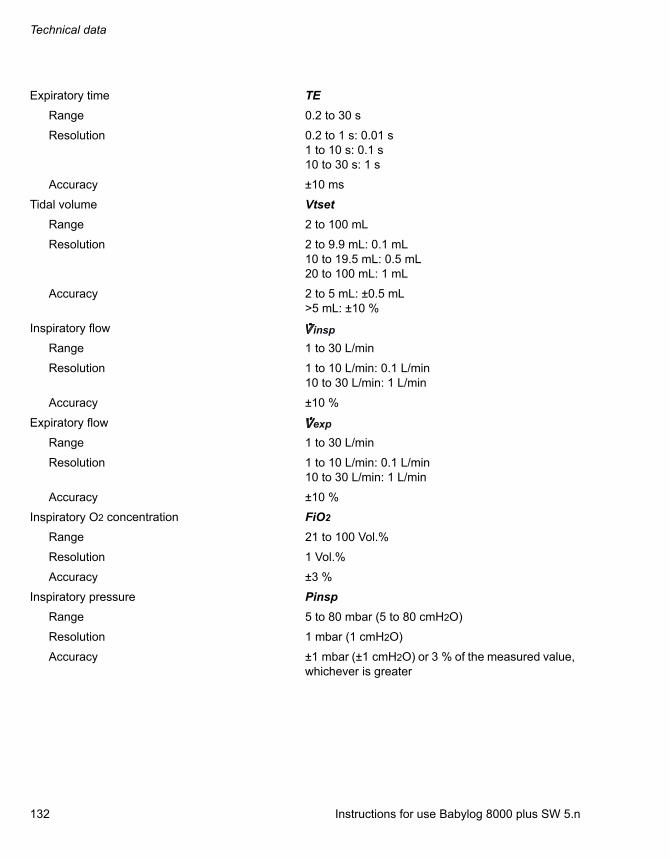
Technical data
132 Instructions for use Babylog 8000 plus SW 5.n
Expiratory time TE
Range 0.2 to 30 s
Resolution 0.2 to 1 s: 0.01 s1 to 10 s: 0.1 s10 to 30 s: 1 s
Accuracy ±10 ms
Tidal volume Vtset
Range 2 to 100 mL
Resolution 2 to 9.9 mL: 0.1 mL10 to 19.5 mL: 0.5 mL20 to 100 mL: 1 mL
Accuracy 2 to 5 mL: ±0.5 mL>5 mL: ±10 %
Inspiratory flow
Range 1 to 30 L/min
Resolution 1 to 10 L/min: 0.1 L/min10 to 30 L/min: 1 L/min
Accuracy ±10 %
Expiratory flow
Range 1 to 30 L/min
Resolution 1 to 10 L/min: 0.1 L/min10 to 30 L/min: 1 L/min
Accuracy ±10 %
Inspiratory O2 concentration FiO2
Range 21 to 100 Vol.%
Resolution 1 Vol.%
Accuracy ±3 %
Inspiratory pressure Pinsp
Range 5 to 80 mbar (5 to 80 cmH2O)
Resolution 1 mbar (1 cmH2O)
Accuracy ±1 mbar (±1 cmH2O) or 3 % of the measured value, whichever is greater
insp
exp

Instructions for use Babylog 8000 plus SW 5.n 133
Technical data
Performance characteristics
Positive end-expiratory pressure or continuous positive airway pressure
PEEP/CPAP
Range 0 to 25 mbar (0 to 25 cmH2O)
Resolution 0 to 10 mbar (0 to 10 cmH2O): 0.1 mbar (0.1 cmH2O)>10 mbar (>10 cmH2O): 1 mbar (1 cmH2O)
Accuracy ±1 mbar (±1 cmH2O) or 3 % of the measured value, whichever is greater
Trigger sensitivity Trig
Range 1 to 10, corresponding to 0.02 to 3 mL
Composition of gas Breathing gas corresponding to the set O2 concen-tration, which can be set to NTPD or BTPS
Control principle Continuous flow, time controlled, pressure limited
O2 is delivered by the integrated air/O2 mixer.
Trigger delay time 40 to 60 ms
Device compliance with breathing circuit without breathing gas humidifier
Prerequisite:
– Inspiratory fraction: approx. 70 %
– Expiratory fraction: approx. 30 %
<1.0 mL/mbar (<1.0 mL/cmH2O)
Device resistance with F&P 8411041 breathing cir-cuit
Insp. Resistance 12 mbar (12 cmH2O) at 30 L/min
Exp. Resistance 5 mbar (5 cmH2O) at 30 L/min
Device resistance with F&P 8411153 HFV breathing circuit
Insp. Resistance 6 mbar (6 cmH2O) at 30 L/min
Exp. Resistance 4 mbar (4 cmH2O) at 30 L/min
Device resistance with other breathing circuits:Only use other breathing circuits if their resistance values do not exceed the above-mentioned values and the inspiratory fraction is approx. 70 %. Other-wise the measurement of the airway pressure may be impaired.

Technical data
134 Instructions for use Babylog 8000 plus SW 5.n
Displayed measured values
Insp. Resistance <11 mbar (<11 cmH2O) at 30 L/min
Exp. Resistance <5 mbar (<5 cmH2O) at 30 L/min
Breathing gas humidifier In accordance with EN ISO 8185
Resistance <20 mbar/L/s (<20 cmH2O/L/s)
Insp. Resistance 12 mbar/L/s (12 cmH2O/L/s)
Exp. Resistance 8 mbar/L/s (8 cmH2O/L/s)
Additional functions
Emergency breathing valve Opens the breathing system in the event of a fault
Safety valve Opens at 90 to 110 mbar (90 to 110 cmH2O)
Subatmospheric pressure in HFV ventilation mode Airway pressure may be subatmospheric during expiration, however it will not fall below –4 mbar (–4 cmH2O) in the event of a fault.
Airway pressure measurement
Sensor 2 piezo-resistive pressure sensors
Range –10 to 100 mbar (–10 to 100 cmH2O)
Zero point error ±1 mbar (±1 cmH2O)
Reinforcement error ±3 % of measured value
Measurement conditions In accordance with ISO 80601-2-12
Peak Inspiratory Pressure Pinsp
Positive end-expiratory pressure PEEP
Mean pressure Mean
Range 0 to 99 mbar (0 to 99 cmH2O)
Resolution 0 to 9.9 mbar (0 to 9.9 cmH2O): 0.1 mbar (0.1 cmH2O)10 to 99 mbar (10 to 99 cmH2O): 1 mbar (1 cmH2O)
Airway pressure
Bar display (on device)
Range –10 to 80 mbar (–10 to 80 cmH2O)
Resolution 2 mbar (2 cmH2O)

Instructions for use Babylog 8000 plus SW 5.n 135
Technical data
Waveform display (on screen)
Range –10 to 100 mbar (–10 to 100 cmH2O)
Resolution –2.5 to 25 mbar (–2.5 to 25 cmH2O): 0.5 mbar (0.5 cmH2O)–5 to 50 mbar (–5 to 50 cmH2O): 1 mbar (1 cmH2O)–10 to 100 mbar (–10 to 100 cmH2O): 2 mbar (2 cmH2O)
Flow and volume measurement
Sensor Hot wire anemometer
Neonatal flow sensor Y-piece (8410185)
Dead space 1.7 mL
Resistance ≤12 mbar (≤12 cmH2O) at 30 L/min
Neonatal flow sensor ISO 15 (8411130)
Dead space 0.9 mL
Resistance ≤11 mbar (≤11 cmH2O) at 30 L/min
Flow
Range 0.2 to 30 L/min
Tidal volume VT
Range 0 to 999 mL
Resolution 0.1 mL
Accuracy ≤5 mL: ±0.5 mL>5 mL: ±10 % of measured value
Minute volume MV
Range 0 to 30 L/min
Resolution 0 to 0.99 L/min: 0.01 L/min1 to 9.9 L/min: 0.1 L/min10 to 30 L/min: 1 L/min
Accuracy(Sensor in standard breathing circuit, endotracheal tube >3 mm (0.12 in))
≤2 L/min: ±0.2 L/min (NTPD)>2 to 30 L/min: ±10 % (NTPD)
Leakage Leak
Range 0 to 100 %
Resolution 1 %
Spontaneous portion of minute volume spont
Range 0 to 100 %
Resolution 1 %

Technical data
136 Instructions for use Babylog 8000 plus SW 5.n
Flow (t) waveform display on screen
Range –20 to 20 L/min
Resolution –2 to 2 L/min: 0.1 L/min–5 to 5 L/min: 0.2 L/min–10 to 10 L/min: 0.4 L/min–20 to 20 L/min: 0.8 L/min
Respiratory rate measurement
Respiratory rate f
Range 0 to 999 bpm
Resolution 0 to 9.9 bpm: 0.1 bpm10 to 999 bpm: 1 bpm
Accuracy ±1 bpm
Inspiratory O2 measurement
Sensor Fuel cell integrated in deviceMeasurement is taken in the inspiratory flow.The sensor is not barometrically pressure compen-sated. In the event of significant air pressure fluctu-ations within a calibration interval (24 hours), it may be necessary to perform a manual calibration.
Inspiratory O2 concentration FiO2
Range 18 to 100 Vol.%
Resolution 1 Vol.%
Accuracy ±3 Vol.% based on the compressed gases O2 and Air
T0...90 <65 s at 1 L/min<10 s at 30 L/min

Instructions for use Babylog 8000 plus SW 5.n 137
Technical data
Displayed calculated measured values
Compliance C
Range 0 to 10 mL/mbar (0 to 10 mL/cmH2O)
Resolution 0.01 mbar (0.01 cmH2O)
Accuracy ±20 %
Resistance R
Range 10 to 999 mbar/L/s (10 to 999 cmH2O/L/s)
Resolution 1 mbar/L/s (1 cmH2O/L/s)
Accuracy ±20 %
Time constant Tc
Range 10 to 999 ms
Resolution 1 ms
Accuracy ±30 %
Overinflation index C20/C
Range 0 to 5
Resolution 0.01
Ratio of f : VT RVR
Range 0 to 1000 bpm/mL
Resolution 0.1 bpm/mL
Transport coefficient DCO2
Range 0 to 999 mL2/s
Resolution 1 mL2/s

Technical data
138 Instructions for use Babylog 8000 plus SW 5.n
Monitoring functions
Sound pressure level LPA of alarm signals mea-sured in accordance with IEC 60601-1-8:Defined operating position: Front of the device at a distance of 1 m (39 in) and a height of 1.5 m (59 in).
Sound pressure
Range for high-priority alarms according to volume setting
63 dB (A) to 83 dB (A)
Range for low- and medium-priority alarms according to volume setting
63 dB (A) to 82 dB (A)
Power supply failure alarm 53 dB (A)
Expiratory minute volume MV
Upper alarm limit alarm If the upper alarm limit has been exceeded
Range 0.10 to 0.99 L/min in steps of 0.01 L/min1.0 to 9.9 L/min in steps of 0.1 L/min10 to 15 L/min in steps of 1 L/min
Lower alarm limit alarm If the lower alarm limit has been exceeded
Range 0 to 0.99 L/min in steps of 0.01 L/min1.0 to 9.9 L/min in steps of 0.1 L/min10 to 14 L/min in steps of 1 L/min
Alarm suppression For the duration of the set alarm delay time
Apnea alarm time Apnoea time
Alarm If no breathing activity is detected
Range 5 to 20 s in steps of 1 s>20 s: monitoring is deactivated
Respiratory rate (panting breathing) Panting
Alarm If the alarm limit has been exceeded
Range 20 to 200 bpm<20 bpm: monitoring is deactivated
Alarm delay time Alarm delay Delays the following alarms:
– MV high
– VT low Check settings!
Range 0 to 30 s
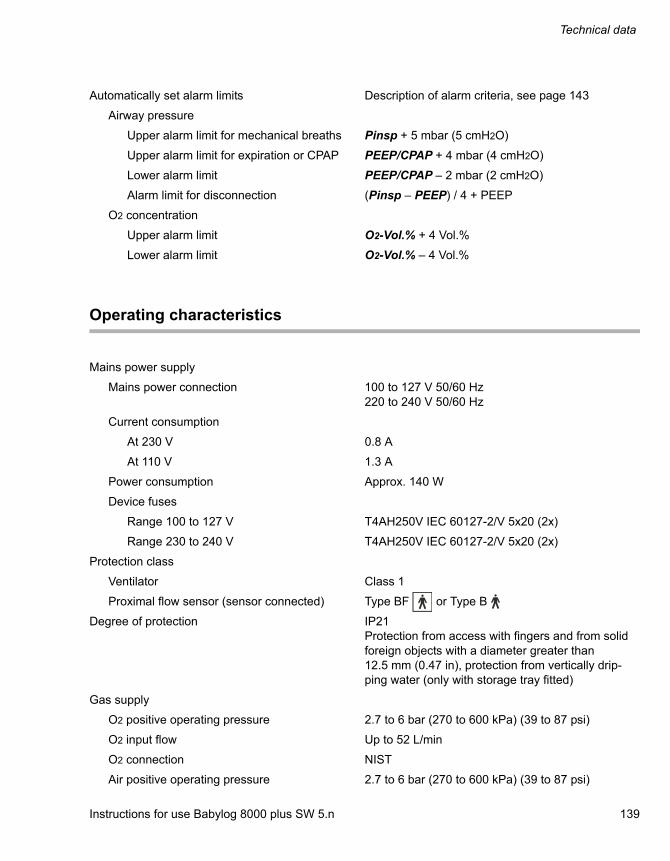
Instructions for use Babylog 8000 plus SW 5.n 139
Technical data
Operating characteristics
Automatically set alarm limits Description of alarm criteria, see page 143
Airway pressure
Upper alarm limit for mechanical breaths Pinsp + 5 mbar (5 cmH2O)
Upper alarm limit for expiration or CPAP PEEP/CPAP + 4 mbar (4 cmH2O)
Lower alarm limit PEEP/CPAP – 2 mbar (2 cmH2O)
Alarm limit for disconnection (Pinsp – PEEP) / 4 + PEEP
O2 concentration
Upper alarm limit O2-Vol.% + 4 Vol.%
Lower alarm limit O2-Vol.% – 4 Vol.%
Mains power supply
Mains power connection 100 to 127 V 50/60 Hz220 to 240 V 50/60 Hz
Current consumption
At 230 V 0.8 A
At 110 V 1.3 A
Power consumption Approx. 140 W
Device fuses
Range 100 to 127 V T4AH250V IEC 60127-2/V 5x20 (2x)
Range 230 to 240 V T4AH250V IEC 60127-2/V 5x20 (2x)
Protection class
Ventilator Class 1
Proximal flow sensor (sensor connected) Type BF or Type B
Degree of protection IP21Protection from access with fingers and from solid foreign objects with a diameter greater than 12.5 mm (0.47 in), protection from vertically drip-ping water (only with storage tray fitted)
Gas supply
O2 positive operating pressure 2.7 to 6 bar (270 to 600 kPa) (39 to 87 psi)
O2 input flow Up to 52 L/min
O2 connection NIST
Air positive operating pressure 2.7 to 6 bar (270 to 600 kPa) (39 to 87 psi)
Technical data
140 Instructions for use Babylog 8000 plus SW 5.n
Air connection NIST
Dew point 5 °C below ambient temperature
Oil concentration <0.1 mg/m3
Particle size Dust-free air (filtered with pore size <1 µm)
Gas consumption
For control Approx. 3 L/min Air
For ejector 11 L/min
Total ≤52 L/min Air or O2
Noise emission of the device during ventilation with typical settings (mean sound pressure level Leq(A))(Average over four sides in a free field in accor-dance with ISO 3744 at a distance of 1 m (39 in) and at a height of 1.5 m (59 in))
≤55 dB(A)≤57.5 dB(A) for HFV or maximum flow
Dimensions (width x height x depth)
Basic device 212 mm x 280 mm x 390 mm(8.4 in x 11.0 in x 15.4 in)
Device with trolley 550 mm x 1273 mm x 559 mm(21.7 in x 50.1 in x 22.0 in)
Weight
Basic device Approx. 14.5 kg (32 lbs)
Maximum load
Trolley load 100 kg (220.4 lbs)
Lateral standard rail load 5 kg (11.0 lbs)
Holder load 10 kg (22.0 lbs)
Electromagnetic compatibility (EMC) according to Directive 89/336/EEC
Tested in accordance with IEC 60601-1-2
Classification according to EC Directive 93/42/EEC, Annex IX
II b
UMDNS code Universal Medical Device Nomencla-ture System
14-361
Materials used
Breathing hose Silicone rubber, Hytrel (milky, transparent, white)
Water trap Polysulphone (gray, transparent)
Y-piece Polysulphone (yellow, transparent)
Expiratory valve (housing, muffler) Aluminum (gray)
Inspiratory valve Aluminum (gray)
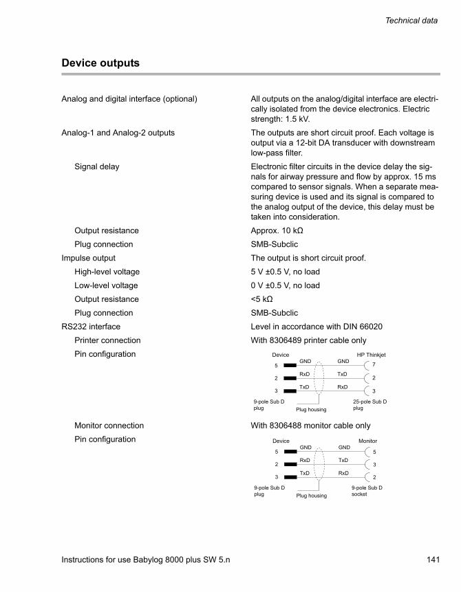
Instructions for use Babylog 8000 plus SW 5.n 141
Technical data
Device outputs
Analog and digital interface (optional) All outputs on the analog/digital interface are electri-cally isolated from the device electronics. Electric strength: 1.5 kV.
Analog-1 and Analog-2 outputs The outputs are short circuit proof. Each voltage is output via a 12-bit DA transducer with downstream low-pass filter.
Signal delay Electronic filter circuits in the device delay the sig-nals for airway pressure and flow by approx. 15 ms compared to sensor signals. When a separate mea-suring device is used and its signal is compared to the analog output of the device, this delay must be taken into consideration.
Output resistance Approx. 10 kΩ
Plug connection SMB-Subclic
Impulse output The output is short circuit proof.
High-level voltage 5 V ±0.5 V, no load
Low-level voltage 0 V ±0.5 V, no load
Output resistance <5 kΩ
Plug connection SMB-Subclic
RS232 interface Level in accordance with DIN 66020
Printer connection With 8306489 printer cable only
Pin configuration
Monitor connection With 8306488 monitor cable only
Pin configuration
Technical data
142 Instructions for use Babylog 8000 plus SW 5.n
Essential performance characteristics
The essential performance consists in a controlled and monitored patient ventilation with user-defined settings for the monitoring functions
– minimum breathing gas flow,
– maximum airway pressure,
– minimum and maximum O2 concentration in the breathing gas,
or, if a set limit is exceeded, an appropriate alarm.
Integrated monitoring also generates an alarm in the following situations:
– Failure of the external power supply
– Failure of the gas supply (O2 and compressed air)
An additional performance characteristic is the prevention of backflow of gas into the central gas supply system.

Instructions for use Babylog 8000 plus SW 5.n 143
Technical data
Alarm criteria
Alarm-triggering parameter Alarm criteria
Inspiratory O2 concentration If the measured inspiratory O2 concentration FiO2 is more than 4 Vol.% above or below the set value for longer than 25 seconds, an alarm is triggered.
Disconnection If the breathing circuit is disconnected or if there is a large leak-age, insufficient or no ventilation pressure is built up. Detection is dependent on whether a minimum pressure is reached. This mini-mum pressure depends on the operating mode and the set values PEEP and Pinsp. When the device is in IPPV/IMV, SIPPV, or SIMV ventilation mode, if the airway pressure is not greater than the minimum pressure PEEP + (Pinsp – PEEP) / 4 for at least 0.025 seconds in every breathing cycle, an alarm is generated.
When the PEEP is set to <2.5 mbar (2.5 cmH2O), disconnection or extubation may not be detected by the integrated pressure moni-toring system, and an alarm cannot be triggered. Additional venti-lation and patient monitoring are therefore necessary.
Inspiratory pressure high Airway pressure must not exceed the set pressure limitation during mandatory inspiration. The limitation may be exceeded by max. 5 mbar (5 cmH2O) so that coughing, for instance, will not trigger an alarm. Above the alarm threshold of Pinsp + 5 mbar (5 cmH2O), the pressure-time integral of the excess pressure is calculated. If the pressure-time integral exceeds 0.33 mbar x s (0.33 cmH2O x s), an alarm is triggered. Simultaneously, manda-tory inspiration is interrupted.
Example: Airway pressure rises to 6 mbar (6 cmH2O) above the pressure limitation Pinsp and then remains constant. An alarm will be triggered after 0.33 seconds. If the pressure-time integral con-tinues to rise after the alarm and exceeds 0.58 mbar x s (0.58 cmH2O x s), ventilation will be interrupted and the breathing circuit will be vented.
CPAP pressure high When operating in CPAP ventilation mode, if airway pressure is continuously above the threshold of PEEP/CPAP + 4 mbar (4 cmH2O) for longer than 5 seconds in the expiration phases of the mandatory ventilation modes, an alarm is triggered. Simultane-ously, the breathing circuit is vented. If airway pressure is greater than PEEP/CPAP + 25 mbar (25 cmH2O), the alarm and venting will be triggered after only 0.3 seconds.
CPAP pressure low If airway pressure falls below PEEP/CPAP – 2 mbar (2 cmH2O) and the pressure-time integral exceeds 6 mbar x s (6 cmH2O x s), an alarm is triggered.
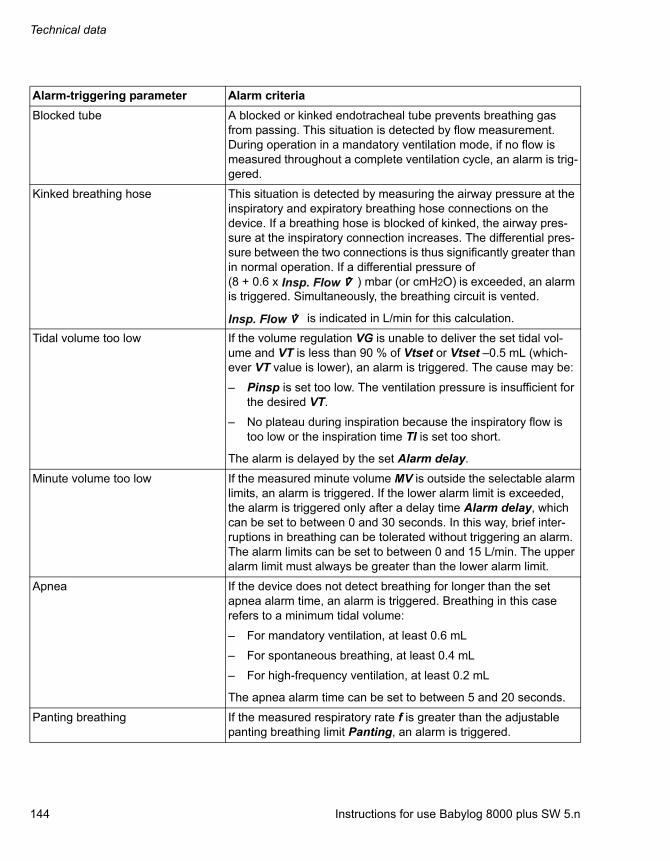
Technical data
144 Instructions for use Babylog 8000 plus SW 5.n
Blocked tube A blocked or kinked endotracheal tube prevents breathing gas from passing. This situation is detected by flow measurement. During operation in a mandatory ventilation mode, if no flow is measured throughout a complete ventilation cycle, an alarm is trig-gered.
Kinked breathing hose This situation is detected by measuring the airway pressure at the inspiratory and expiratory breathing hose connections on the device. If a breathing hose is blocked of kinked, the airway pres-sure at the inspiratory connection increases. The differential pres-sure between the two connections is thus significantly greater than in normal operation. If a differential pressure of (8 + 0.6 x ) mbar (or cmH2O) is exceeded, an alarm is triggered. Simultaneously, the breathing circuit is vented.
is indicated in L/min for this calculation.
Tidal volume too low If the volume regulation VG is unable to deliver the set tidal vol-ume and VT is less than 90 % of Vtset or Vtset –0.5 mL (which-ever VT value is lower), an alarm is triggered. The cause may be:
– Pinsp is set too low. The ventilation pressure is insufficient for the desired VT.
– No plateau during inspiration because the inspiratory flow is too low or the inspiration time TI is set too short.
The alarm is delayed by the set Alarm delay.
Minute volume too low If the measured minute volume MV is outside the selectable alarm limits, an alarm is triggered. If the lower alarm limit is exceeded, the alarm is triggered only after a delay time Alarm delay, which can be set to between 0 and 30 seconds. In this way, brief inter-ruptions in breathing can be tolerated without triggering an alarm. The alarm limits can be set to between 0 and 15 L/min. The upper alarm limit must always be greater than the lower alarm limit.
Apnea If the device does not detect breathing for longer than the set apnea alarm time, an alarm is triggered. Breathing in this case refers to a minimum tidal volume:
– For mandatory ventilation, at least 0.6 mL
– For spontaneous breathing, at least 0.4 mL
– For high-frequency ventilation, at least 0.2 mL
The apnea alarm time can be set to between 5 and 20 seconds.
Panting breathing If the measured respiratory rate f is greater than the adjustable panting breathing limit Panting, an alarm is triggered.
Alarm-triggering parameter Alarm criteria
Insp. Flow
Insp. Flow

Instructions for use Babylog 8000 plus SW 5.n 145
Technical data
Safety principle
Babylog 8000 is a software-driven device. The safety concept is based on 2 microprocessor systems that function independently of one another and monitor each other's functions. The measurement and alarm functions required to do this are thus doubled.

Technical data
146 Instructions for use Babylog 8000 plus SW 5.n
EMC Declaration
General information
The EMC compliance of the product has been evaluated with the external cables, transducers, and accessories specified in the list of accessories. Other accessories which do not affect EMC compliance may be used if no other reasons forbid their use (see other sections of the instructions for use).The use of noncompliant accessories can result in increased emissions or decreased immunity of the medical device.
The medical device must only be used adjacent to or stacked with other devices if this configuration is approved by Dräger. If adjacent or stacked use of configurations not approved by Dräger is inevitable, verify correct functioning of the medical device in this configuration before it is used. In any case, strictly observe the instructions for use of the other devices.
Electromagnetic emissions
When using wireless networking, be aware that the system operates at 2.4 GHz range. Other equipment, even if compliant with CISPR emission requirements, can interfere with reception of wireless data. When selecting wireless systems (wireless communication media, pager systems, etc.) for use in installations where wireless networking is used, care must always be used to ensure that operating frequencies are compatible. For example, selecting wireless communication media that operate at 2.4 GHz will likely cause difficulty with the networking components. Low-level signals such as ECG signals are particular susceptible to interference from electromagnetic energy. Even if the equipment meets the test requirements described below, smooth operation cannot be guaranteed – the ‘quieter‘ the electrical environment the better. In general, increasing the distance between electrical devices decreases the likelihood of interference.
Detailed radio frequency characteristics
Communication devices in accordance with IEEE 802.11b:
– 2412 to 2472 MHz
– DSSS (direct-sequence spread spectrum) limited to 100 mW
– Applicable to access points and client adapters
Communication devices in accordance with IEEE 802.15.1:
– 2400 to 2485 MHz
– FHSS (frequency-hopping spread spectrum) limited to 2.5 mW
See the instructions for use of the wireless devices for further details.

Instructions for use Babylog 8000 plus SW 5.n 147
Technical data
Electromagnetic environment
The medical device is intended for use in an electromagnetic environment as specified below. The user must ensure that the medical device is used in such an environment.
Emissions Compliance according to Electromagnetic environment
Radio frequency emissions (CISPR 11)
Group 1 The medical device uses radio frequency energy only for its internal function. Therefore, its radio frequency emissions are very low and are not likely to cause any interference in nearby electronic equipment.
Class A The medical device is suitable for use in all establishments other than domestic establishments and those directly connected (without transformer) to the public low-voltage power supply net-work that supplies buildings used for domestic purposes.
Harmonic emissions (IEC 61000-3-2)
Not applicable
Voltage fluctuations/flicker emis-sions (IEC 61000-3-3)
Not applicable
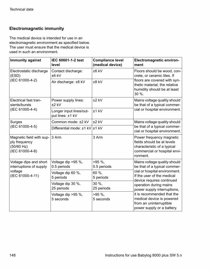
Technical data
148 Instructions for use Babylog 8000 plus SW 5.n
Electromagnetic immunity
The medical device is intended for use in an electromagnetic environment as specified below. The user must ensure that the medical device is used in such an environment.
Immunity against IEC 60601-1-2 test level
Compliance level (medical device)
Electromagnetic environ-ment
Electrostatic discharge (ESD)(IEC 61000-4-2)
Contact discharge: ±6 kV
±6 kV Floors should be wood, con-crete, or ceramic tiles. If floors are covered with syn-thetic material, the relative humidity should be at least 30 %.
Air discharge: ±8 kV ±8 kV
Electrical fast tran-sients/bursts(IEC 61000-4-4)
Power supply lines: ±2 kV
±2 kV Mains voltage quality should be that of a typical commer-cial or hospital environment.Longer input lines/out-
put lines: ±1 kV±1 kV
Surges(IEC 61000-4-5)
Common mode: ±2 kV ±2 kV Mains voltage quality should be that of a typical commer-cial or hospital environment.
Differential mode: ±1 kV ±1 kV
Magnetic field with sup-ply frequency (50/60 Hz)(IEC 61000-4-8)
3 A/m 3 A/m Power frequency magnetic fields should be at levels characteristic of a typical commercial or hospital envi-ronment.
Voltage dips and short interruptions of supply voltage(IEC 61000-4-11)
Voltage dip >95 %,0.5 periods
>95 %,0.5 periods
Mains voltage quality should be that of a typical commer-cial or hospital environment. If the user of the medical device requires continued operation during mains power supply interruptions, it is recommended that the medical device is powered from an uninterruptible power supply or a battery.
Voltage dip 60 %,5 periods
60 %,5 periods
Voltage dip 30 %,25 periods
30 %,25 periods
Voltage dip >95 %,5 seconds
>95 %,5 seconds

Instructions for use Babylog 8000 plus SW 5.n 149
Technical data
Radiated radio fre-quency disturbance(IEC 61000-4-3)
80 MHz to 2.5 GHz:10 V/m
10 V/m Recommended minimum distance to portable and mobile radio frequency transmitters with transmis-sion power PEIRP to the medical device including its lines:1)
Conducted radio fre-quency disturbance(IEC 61000-4-6)
150 kHz to 80 MHz:10 V inside ISM bands2)
10 V Recommended minimum distance from portable and mobile radio frequency transmitters with transmis-sion power PEIRP to the medical device including its lines: 1)
150 kHz to 80 MHz:3 V outside ISM bands2)
3 V
1) For PEIRP, insert the highest possible "equivalent isotropic radiated power" of the adjacent radio frequency transmitter. In the vicinity of equipment marked with the symbol , interference can occur. Field strengths from fixed, portable, or mobile radio frequency transmitters at the location of the medical device should be less than 3 V/m in the frequency range from 150 kHz to 2.5 GHz and less than 1 V/m above 2.5 GHz.
2) ISM bands in this frequency range are: 6.765 MHz to 6.795 MHz; 13.553 MHz to 13.567 MHz; 26.957 MHz to 27.283 MHz; 40.66 MHz to 40.70 MHz.
Immunity against IEC 60601-1-2 test level
Compliance level (medical device)
Electromagnetic environ-ment
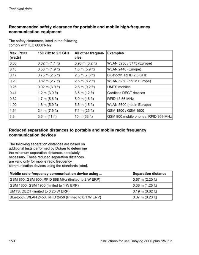
Technical data
150 Instructions for use Babylog 8000 plus SW 5.n
Recommended safety clearance for portable and mobile high-frequency communication equipment
The safety clearances listed in the following comply with IEC 60601-1-2.
Reduced separation distances to portable and mobile radio frequency communication devices
The following separation distances are based on additional tests performed by Dräger to determine the minimum separation distances absolutely necessary. These reduced separation distances are valid only for mobile radio frequency communication devices using the standards listed.
Max. PEIRP (watts)
150 kHz to 2.5 GHz All other frequen-cies
Examples
0.03 0.32 m (1.1 ft) 0.96 m (3.2 ft) WLAN 5250 / 5775 (Europe)
0.10 0.58 m (1.9 ft) 1.8 m (5.9 ft) WLAN 2440 (Europe)
0.17 0.76 m (2.5 ft) 2.3 m (7.6 ft) Bluetooth, RFID 2.5 GHz
0.20 0.82 m (2.7 ft) 2.5 m (8.2 ft) WLAN 5250 (not in Europe)
0.25 0.92 m (3.0 ft) 2.8 m (9.2 ft) UMTS mobiles
0.41 1.2 m (3.9 ft) 3.5 m (12 ft) Cordless DECT devices
0.82 1.7 m (5.6 ft) 5.0 m (16 ft) RFID 13.56 MHz
1.00 1.8 m (5.9 ft) 5.5 m (18 ft) WLAN 5600 (not in Europe)
1.64 2.4 m (7.9 ft) 7.1 m (23 ft) GSM 1800 / GSM 1900
3.3 3.3 m (11 ft) 10 m (33 ft) GSM 900 mobile phones, RFID 868 MHz
Mobile radio frequency communication device using ... Separation distance
GSM 850, GSM 900, RFID 868 MHz (limited to 2 W ERP) 0.67 m (2.20 ft)
GSM 1800, GSM 1900 (limited to 1 W ERP) 0.38 m (1.25 ft)
UMTS, DECT (limited to 0.25 W ERP) 0.19 m (0.62 ft)
Bluetooth, WLAN 2450, RFID 2450 (limited to 0.1 W ERP) 0.07 m (0.23 ft)

Instructions for use Babylog 8000 plus SW 5.n 151
Technical data
Connection to IT networks
Data can be exchanged in an IT network using wired and wireless technologies. IT networks include all data interfaces (e.g., RS232, LAN, USB, printer interface) described in standards and conventions.
Information for connection to an IT network
Preconditions
The device must only be connected to the network by service personnel. The head of IT at the hospital must be consulted in advance.
The following documents must be observed:
– Documentation accompanying this device
– Description of the network interface
– Description of network-based alarm systems
Dräger recommends observing IEC 80001-1 (risk management for IT networks with medical devices).
Serial interfaces
The following interfaces are possible:
– RS232 interfaces according to EIA RS-232 (CCITT V.24/V.28) for the following applications:
– MEDIBUS
– Connections with third-party medical devices
Electrical requirements for connected devices and networks
The serial interface is only appropriate for connecting devices or networks that have a nominal voltage on the network side of max. 24 V DC and meet the requirements of one of the following standards:
– IEC 60950-1: Ungrounded SELV electrical circuits
– IEC 60601-1 (2nd edition or later): Exposed secondary circuits
Principles of operation
152 Instructions for use Babylog 8000 plus SW 5.n
Principles of operation
Pneumatic function description................... 153
Pneumatic circuit diagram (simplified)............. 153Description of the pneumatic mode of operation ......................................................... 154
Description of ventilation modes................. 156
Continuous Positive Airway Pressure (CPAP) 156Intermittent Positive Pressure Ventilation / Intermittent Mandatory Ventilation (IPPV/IMV) 156Synchronized Intermittent Positive Pressure Ventilation (SIPPV).......................................... 158Synchronized Intermittent Mandatory Ventilation (SIMV) ........................................... 159Pressure Support Ventilation (PSV) ................ 160
Additional settings for ventilation ............... 161
Volume Guarantee (VG).................................. 161Separate expiratory flow.................................. 162High-frequency ventilation (HFV) .................... 162
Measurements ............................................... 165
Airway pressure measurement........................ 165Flow and volume measurement ...................... 165
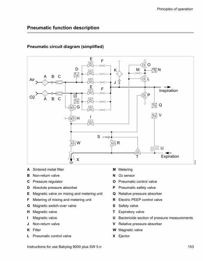
Instructions for use Babylog 8000 plus SW 5.n 153
Principles of operation
Pneumatic function description
Pneumatic circuit diagram (simplified)
A Sintered metal filter
B Non-return valve
C Pressure regulator
D Absolute pressure absorber
E Magnetic valve on mixing and metering unit
F Metering of mixing and metering unit
G Magnetic switch-over valve
H Magnetic valve
I Magnetic valve
J Non-return valve
K Filter
L Pneumatic control valve
M Metering
N O2 sensor
O Pneumatic control valve
P Pneumatic safety valve
Q Relative pressure absorber
R Electric PEEP control valve
S Safety valve
T Expiratory valve
U Bactericide section of pressure measurements
V Relative pressure absorber
W Magnetic valve
X Ejector
21
91
3

Principles of operation
154 Instructions for use Babylog 8000 plus SW 5.n
Description of the pneumatic mode of operation
Gas supply
The compressed gases Air and O2 are delivered via the filters (A) and non-return valves (B) to the pressure regulators (C), which generate constant pressure for both gases. The non-return valves (B) prevent the gas from flowing back into the central gas supply.
The absolute pressure absorbers (D) measure and monitor system pressure. Air and O2 is diverted after the pressure regulators (C) and directed to the magnetic valve (G), which directs control air or calibration gas through the magnetic valve (H) to the magnetic valves (I) and (W), to the safety valve (P), to the PEEP control valve (R), and to the expiration valve (T). Both gases are directed from the pressure regulators (C) to the magnetic valves (E) and metering systems (F), which mix and meter both gases. The gas mixture flows via the inspiratory line to the patient.
In the event that the gas supply fails, ambient air can be drawn in through the filter (K) and the non-return valve (J). The non-return valve (J) prevents breathing gas from escaping into the environment.
Controlled ventilation
The continuous flow flows via the inspiratory line to the Y-piece.
The inspiratory oxygen concentration is measured at the O2 sensor (N) by the open pneumatic control valve (L).
The safety valve (P) is opened if a detected stenosis impedes depressurization in the expiratory branch.
Inspiration
The expiratory valve (T) is activated by the PEEP control valve (R) and closes the expiratory line. The continuous flow flows into the patient's lungs. The airway pressure is measured with the two relative pressure absorbers (Q) and (V). The inspiratory pressure limitation is regulated via the expiratory valve (T).
Expiration
The PEEP control valve (R) vents the control pressure at the expiratory valve (T). The expiratory valve opens the breathing system. The breath is expired via the open expiratory valve (T). The ejector (X) is activated by the open magnetic valve (W) and supports expiration.
PEEP
The PEEP control valve (R) generates a control pressure, which regulates the PEEP in the breathing system, on the control side of the expiratory valve (T).
CPAP
The control pressure generated by the PEEP control valve (R) affects the control side of the expiratory valve (T) and produces a continuous positive airway pressure in the breathing system. The continuous flow flows via the Y-piece and expiratory valve (T).
Instructions for use Babylog 8000 plus SW 5.n 155
Principles of operation
O2 concentration measurement
The O2 sensor (N) continuously measures the inspriatory O2 concentration via the pneumatic control valve (L).
An automatic two-point calibration is performed regularly every 24 hours: Air is directed to the pneumatic control valve (L) via the magnetic valves (G), (H) and (I). This closes the connection between the O2 sensor (N) and the inspiratory line. The pneumatic control valve (O) is opened while the O2 sensor (N) is simultaneously flushed with air via the metering system (M) for approx. 2.5 minutes. The sensor is then flushed with O2 in a similar manner. After the calibration, the magnetic valve (G) switches back to air, the magnetic valve (I) closes, the pneumatic control valve (O) closes, and the pneumatic control valve (L) reconnects the O2 sensor with the inspriatory line.
Airway pressure measurement
The two relative pressure absorbers (Q) and (V) determine the pressure on the entry and exit sides of the breathing circuit. The device determines the airway pressure at the Y-piece by means of the pressure drop caused by the continuous flow in the breathing circuit.
The bactericide section of pressure measurements (U) prevents contamination of the pressure absorber (V) with expiration gas.
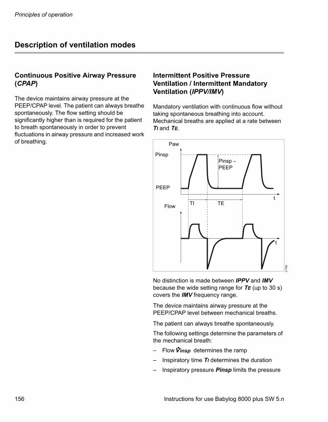
Principles of operation
156 Instructions for use Babylog 8000 plus SW 5.n
Description of ventilation modes
Continuous Positive Airway Pressure (CPAP)
The device maintains airway pressure at the PEEP/CPAP level. The patient can always breathe spontaneously. The flow setting should be significantly higher than is required for the patient to breath spontaneously in order to prevent fluctuations in airway pressure and increased work of breathing.
Intermittent Positive Pressure Ventilation / Intermittent Mandatory Ventilation (IPPV/IMV)
Mandatory ventilation with continuous flow without taking spontaneous breathing into account. Mechanical breaths are applied at a rate between TI and TE.
No distinction is made between IPPV and IMV because the wide setting range for TE (up to 30 s) covers the IMV frequency range.
The device maintains airway pressure at the PEEP/CPAP level between mechanical breaths.
The patient can always breathe spontaneously.
The following settings determine the parameters of the mechanical breath:
– Flow determines the ramp
– Inspiratory time TI determines the duration
– Inspiratory pressure Pinsp limits the pressure
211
68
Paw
Pinsp
PEEP
Pinsp – PEEP
TETIFlow
t
t
insp

Instructions for use Babylog 8000 plus SW 5.n 157
Principles of operation
When the pressure reaches Pinsp, a pressure plateau is created. If Pinsp is not reached, the pressure curve has a sharp peak.
The pressure pattern determines what the tidal volume VT depends on. The following two cases show the relationship:
Case 1, long plateau:If the plateau is so long that the inspiratory flow has fallen to zero by the end of TI, lung pressure has reached airway pressure. The ventilation pressure (the difference between Pinsp and PEEP) then controls the tidal volume:VT = (Pinsp – PEEP) x CrsCrs: compliance of the respiratory system
Case 2, no plateau:Without an inspiratory plateau Pinsp has no influence. Part of the flow fills the breathing circuit with each mechanical breath and does not reach the lungs. Part of the ventilation solely occurs in the breathing circuit. The tidal volume can be approximated as follows:VT = TI x x (Crs / (Crs + Cs))Cs: compliance of the breathing circuit
Especially in very small patients, the effect of the breathing circuit can be detrimental because Cs and Crs are of equal magnitude.
Example:If Crs = Cs = 0.5 mL/mbar (0.5 mL/cmH2O) only half of the set flow reaches the lungs.
This effect of ventilating the breathing circuit occurs with any ventilator. The flow sensor in Babylog 8000 is located at the Y-piece in order to measure the tidal volume that is actually inhaled and exhaled.
insp
insp
211
69
Paw
Pinsp
PEEP
Flow TI TE
t
t
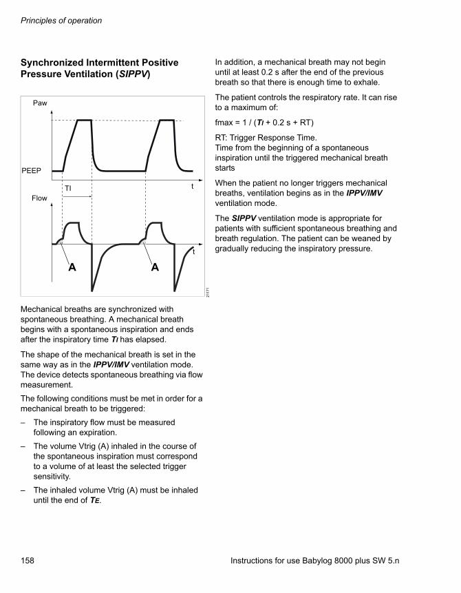
Principles of operation
158 Instructions for use Babylog 8000 plus SW 5.n
Synchronized Intermittent Positive Pressure Ventilation (SIPPV)
Mechanical breaths are synchronized with spontaneous breathing. A mechanical breath begins with a spontaneous inspiration and ends after the inspiratory time TI has elapsed.
The shape of the mechanical breath is set in the same way as in the IPPV/IMV ventilation mode. The device detects spontaneous breathing via flow measurement.
The following conditions must be met in order for a mechanical breath to be triggered:
– The inspiratory flow must be measured following an expiration.
– The volume Vtrig (A) inhaled in the course of the spontaneous inspiration must correspond to a volume of at least the selected trigger sensitivity.
– The inhaled volume Vtrig (A) must be inhaled until the end of TE.
In addition, a mechanical breath may not begin until at least 0.2 s after the end of the previous breath so that there is enough time to exhale.
The patient controls the respiratory rate. It can rise to a maximum of:
fmax = 1 / (TI + 0.2 s + RT)
RT: Trigger Response Time.Time from the beginning of a spontaneous inspiration until the triggered mechanical breath starts
When the patient no longer triggers mechanical breaths, ventilation begins as in the IPPV/IMV ventilation mode.
The SIPPV ventilation mode is appropriate for patients with sufficient spontaneous breathing and breath regulation. The patient can be weaned by gradually reducing the inspiratory pressure.
211
71
Paw
PEEP
TI t
t
Flow
A A
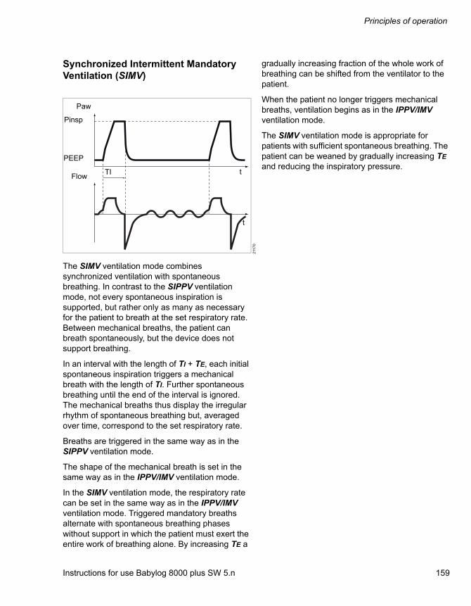
Instructions for use Babylog 8000 plus SW 5.n 159
Principles of operation
Synchronized Intermittent Mandatory Ventilation (SIMV)
The SIMV ventilation mode combines synchronized ventilation with spontaneous breathing. In contrast to the SIPPV ventilation mode, not every spontaneous inspiration is supported, but rather only as many as necessary for the patient to breath at the set respiratory rate. Between mechanical breaths, the patient can breath spontaneously, but the device does not support breathing.
In an interval with the length of TI + TE, each initial spontaneous inspiration triggers a mechanical breath with the length of TI. Further spontaneous breathing until the end of the interval is ignored. The mechanical breaths thus display the irregular rhythm of spontaneous breathing but, averaged over time, correspond to the set respiratory rate.
Breaths are triggered in the same way as in the SIPPV ventilation mode.
The shape of the mechanical breath is set in the same way as in the IPPV/IMV ventilation mode.
In the SIMV ventilation mode, the respiratory rate can be set in the same way as in the IPPV/IMV ventilation mode. Triggered mandatory breaths alternate with spontaneous breathing phases without support in which the patient must exert the entire work of breathing alone. By increasing TE a
gradually increasing fraction of the whole work of breathing can be shifted from the ventilator to the patient.
When the patient no longer triggers mechanical breaths, ventilation begins as in the IPPV/IMV ventilation mode.
The SIMV ventilation mode is appropriate for patients with sufficient spontaneous breathing. The patient can be weaned by gradually increasing TE and reducing the inspiratory pressure.
211
70
Paw
Pinsp
PEEP
FlowTI t
t

Principles of operation
160 Instructions for use Babylog 8000 plus SW 5.n
Pressure Support Ventilation (PSV)
The PSV ventilation mode functions largely like the SIPPV ventilation mode. In addition to the respiratory rate, in the PSV ventilation mode the patient also controls the duration of the mechanical breath using the flow. The mandatory inspiration ends when the flow falls to 15 % of the maximum inspiratory flow, but no later than after the selected inspiratory time TI.
In order for the inspiratory flow to be able to fall over the course of the mechanical breath, the pressure pattern must have a plateau (cf. description of IPPV/IMV). The lung pressure, which increases as the lungs are filled, then adapts to the airway pressure, and the flow decreases.
The speed with which the lung pressure adapts to the airway pressure depends on the time constant Trs of the respiratory system. The shorter Trs, the faster the lungs fill. Thus, in the PSV ventilation mode, the mechanical breath ends when the lungs are nearly full. The effective inspiratory time is optimized for the patient.
Breaths are triggered in the same way as in the SIPPV ventilation mode.
The shape of the mechanical breath, with the exception of the inspiratory time, is set in the same way as in the IPPV/IMV ventilation mode. If the plateau is too short, the mechanical breath ends after TI as in the SIPPV ventilation mode.
When the patient no longer triggers mechanical breaths, ventilation begins as in the IPPV/IMV ventilation mode.
The PSV ventilation mode is appropriate for patients with sufficient spontaneous breathing and breath regulation. The patient can be weaned by gradually reducing the support pressure.
211
71
Paw
Pinsp
PEEP
FlowTI t
t
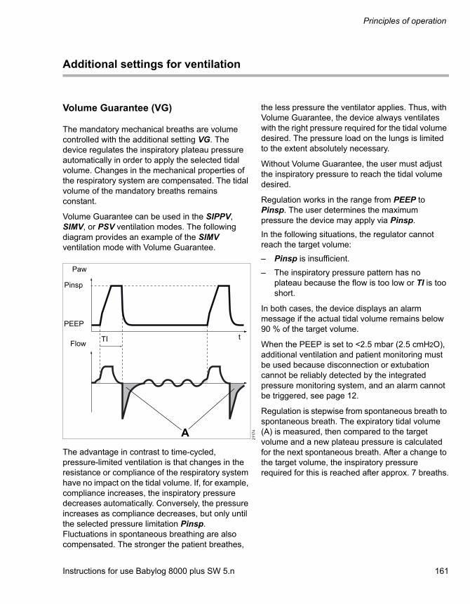
Instructions for use Babylog 8000 plus SW 5.n 161
Principles of operation
Additional settings for ventilation
Volume Guarantee (VG)
The mandatory mechanical breaths are volume controlled with the additional setting VG. The device regulates the inspiratory plateau pressure automatically in order to apply the selected tidal volume. Changes in the mechanical properties of the respiratory system are compensated. The tidal volume of the mandatory breaths remains constant.
Volume Guarantee can be used in the SIPPV, SIMV, or PSV ventilation modes. The following diagram provides an example of the SIMV ventilation mode with Volume Guarantee.
The advantage in contrast to time-cycled, pressure-limited ventilation is that changes in the resistance or compliance of the respiratory system have no impact on the tidal volume. If, for example, compliance increases, the inspiratory pressure decreases automatically. Conversely, the pressure increases as compliance decreases, but only until the selected pressure limitation Pinsp. Fluctuations in spontaneous breathing are also compensated. The stronger the patient breathes,
the less pressure the ventilator applies. Thus, with Volume Guarantee, the device always ventilates with the right pressure required for the tidal volume desired. The pressure load on the lungs is limited to the extent absolutely necessary.
Without Volume Guarantee, the user must adjust the inspiratory pressure to reach the tidal volume desired.
Regulation works in the range from PEEP to Pinsp. The user determines the maximum pressure the device may apply via Pinsp.
In the following situations, the regulator cannot reach the target volume:
– Pinsp is insufficient.
– The inspiratory pressure pattern has no plateau because the flow is too low or TI is too short.
In both cases, the device displays an alarm message if the actual tidal volume remains below 90 % of the target volume.
When the PEEP is set to <2.5 mbar (2.5 cmH2O), additional ventilation and patient monitoring must be used because disconnection or extubation cannot be reliably detected by the integrated pressure monitoring system, and an alarm cannot be triggered, see page 12.
Regulation is stepwise from spontaneous breath to spontaneous breath. The expiratory tidal volume (A) is measured, then compared to the target volume and a new plateau pressure is calculated for the next spontaneous breath. After a change to the target volume, the inspiratory pressure required for this is reached after approx. 7 breaths.
211
74
Paw
Pinsp
PEEP
TIFlow
t
A
Principles of operation
162 Instructions for use Babylog 8000 plus SW 5.n
In case of major tube leakage (cf. description of leakage rate), the exhaled tidal volume can (as in other ventilation modes as well) be greater than the tidal volume measured on the expiratory side. Then the inspiratory and expiratory tidal volumes are different. If, in the course of a mechanical breath, the current inspiratory tidal volume exceeds the expiratory tidal volume (A) of the previous breath by an amount dependent on the actual leakage rate, the device terminates the inspiration.
If the flow sensor fails or if the patient no longer breathes spontaneously, mandatory ventilation begins as in the IPPV/IMV ventilation mode.
Separate expiratory flow
The additional setting VIVE can be used to set the continuous expiratory flow independent of the continuous inspiratory flow . The inspiratory flow has an effect on mechanical breaths. Expiratory flow has an effect on spontaneous breathing phases and in the CPAP ventilation mode.
Effects of increased expiratory flow:
– Greater flow is made available to the patient for spontaneous breathing than is provided for the mechanical breaths.
– Increased turbulence in the breathing circuit benefits the flushing of the dead space in the Y-piece.
– In the CPAP ventilation mode, the pattern of manually triggered mechanical breaths can be set separately.
A reduced expiratory flow can be used to save oxygen.
High-frequency ventilation (HFV)
Ventilation with high-frequency pressure oscillations enables gas to be exchanged in the lungs despite very small tidal volumes (often in the dead space volume range). While pressure amplitudes may be considerable in the breathing circuit, only small fluctuations occur around the mean pressure in the lungs.The mechanical load due to periodic expansion and relaxation of the lungs is low.
Functional principle:Like the respiratory cycles in conventional mandatory ventilation, high-frequency oscillations are controlled via the diaphragm in the expiratory valve. In the inspiratory phases of the oscillations the pressure is greater than the mean airway pressure; in the expiratory phases it is less than the airway pressure. The mean pressure is automatically regulated to correspond to the set value PEEP/CPAP.
In order to regulate the pressure, the device must automatically set the flow and I:E ratio of the cycles. The setting knob for flow ( ) has no effect during high-frequency oscillation. The additional setting VIVE is likewise unavailable. The pressure amplitudes at the Y-piece depend on the set value for amplitude, as well as on the breathing circuit and on the patient's respiratory system. For this reason, set the amplitude on a relative scale from 0 % to 100 % until the desired pressure is reached or the desired tidal volumes are set.
expinsp
Insp. Flow
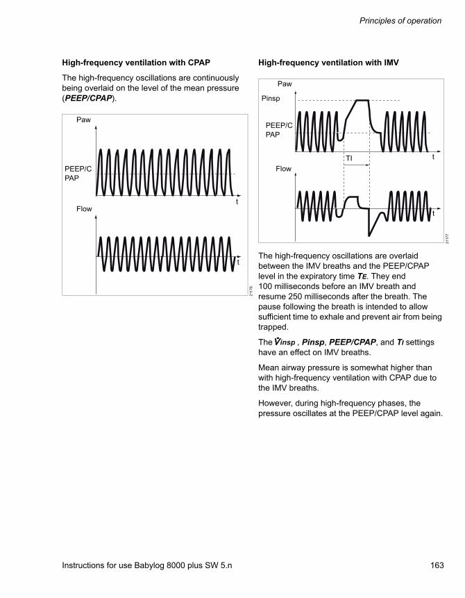
Instructions for use Babylog 8000 plus SW 5.n 163
Principles of operation
High-frequency ventilation with CPAP
The high-frequency oscillations are continuously being overlaid on the level of the mean pressure (PEEP/CPAP).
High-frequency ventilation with IMV
The high-frequency oscillations are overlaid between the IMV breaths and the PEEP/CPAP level in the expiratory time TE. They end 100 milliseconds before an IMV breath and resume 250 milliseconds after the breath. The pause following the breath is intended to allow sufficient time to exhale and prevent air from being trapped.
The , Pinsp, PEEP/CPAP, and TI settings have an effect on IMV breaths.
Mean airway pressure is somewhat higher than with high-frequency ventilation with CPAP due to the IMV breaths.
However, during high-frequency phases, the pressure oscillates at the PEEP/CPAP level again.
211
76
Paw
PEEP/CPAP
Flowt
t
211
77
Paw
PEEP/CPAP
Flow
Pinsp
TI t
t
insp
Principles of operation
164 Instructions for use Babylog 8000 plus SW 5.n
Monitoring of high-frequency ventilation
As in conventional ventilation, the waveforms for pressure and flow are measured and can be displayed. The following are measured specifically for high-frequency ventilation:
DCO2 = VThf 2 x f Transport coefficient for CO2, which, analogous to the minute volume in conventional ventilation, is a measure of high-frequency ventilation.
VThf Tidal volume of the high-frequency pulses, averaged over multiple cycles
MVim Minute volume applied by IMV breaths, measured on the inspiratory side
VTim Tidal volume applied by IMV breaths, measured on the inspiratory side

Instructions for use Babylog 8000 plus SW 5.n 165
Principles of operation
Measurements
Airway pressure measurement
The device measures airway pressure indirectly in order to avoid the need for a hose for pressure measurement on the Y-piece. Within the device, two piezoresistive pressure sensors record the pressures PI at the inspiratory connection and PE at the expiratory connection. These two measured values are used to calculate the airway pressure PY.
Due to operation with continuous flow, the inspiratory pressure PI serves as the reference point. The flow causes a pressure drop P in the inspiratory side of the breathing circuit, which is dependent on the resistance RI in the inspiratory hose and :
P = x RI
P is only minimally dependent on the ventilation pattern. The pressure at the Y-piece is approximately equal to the pressure PI less P:
PY = PI – P = PI – x RI
Thus, the airway pressure at the Y-piece can be calculated if the resistance RI is known.
The total resistance of the breathing circuit can be measured during ventilation using the two sensors for PI and PE; however, the inspiratory fraction cannot be measured.Comprehensive laboratory tests have demonstrated that the inspiratory branch has approx. 70 % of the total resistance in all typical breathing circuits. The device uses this estimated value to calculate the following:
PY = PI – 0.7 x < PI – PE >
< PI – PE >: Represents the pressure drop throughout the entire breathing circuit averaged over time. If a breathing circuit has a resistance distribution of other than 30 % to 70 %, there is a measurement error for the airway pressure. In the breathing circuits typically used, this error is less than 1 mbar (1 cmH2O). In systems with very high
resistance that also have high continuous flow, it may be greater. For this reason, only use breathing circuits with inner diameters of at least 10 mm (0.4 in).
Flow and volume measurement
The measuring principle used for flow measurement is based on hotwire anemometry.
Hot-wire anemometry is a thermal measuring procedure where the measuring wires of the flow sensor are maintained at a constantly high temperature. The higher the flow, the more power is needed to maintain a constantly high temperature. The flow rate can then be calculated from the amount of power consumed.
To ensure correct functioning check the flow sensor for visible damage, soiling, and particles before inserting it. Replace damaged, soiled, or non-particle-free flow sensors.
If the measuring wires of the flow sensor glow continuously during operation, this is a sign of soiling. Immediately reprocess or replace the flow sensor.
The lowest flow at which detection functions reliably is 0.2 L/min. Lower flow values are therefore suppressed and displayed as zero.
insp
insp
insp
insp

Principles of operation
166 Instructions for use Babylog 8000 plus SW 5.n
Flow sensor
Two different sensor types are available:
– The Y-piece flow sensor is integrated in the Y-piece.
– The ISO 15 flow sensor is built in between the Y-piece and the tube connector.
Both sensor types use the same sensor insert. Despite this, the sensor properties are not identical. The sensor type is set in the Calibration/Configuration > Sensor dialog window in order to optimize the measurement for this type of sensor.
Reference conditions
Hot wire manometers primarily measure gas quantities, not volumes or flows. The volume that a certain gas quantity takes up depends on the ambient conditions as expressed in the equation of state for ideal gases:
– Atmospheric pressure
– Temperature
– Humidity
Babylog 8000 indicates flow and volume measured values for one of two reference conditions:
The desired reference condition is set in the dialog window Calibration/Configuration > Sensor.
Leakage rate
In an unblocked tube, breathing gas often flows into the environment from between the trachea wall and the tube. The flow sensor on the device is located in the Y-piece, i.e. upstream from the location of the leakage. During inspiration, breathing gas is lost after measurement; during expiration it is lost before measurement. The tidal volume measured on the inspiratory side is therefore greater and that on the expiratory side less than the actual tidal volume. Averaged over time the difference between the inspiratory flow and expiratory flow is equal to the leakage flow because the gas quantity that does not flow back through the sensor during exhalation must have escaped through the leak. The device determines the mean leakage flow from the difference between inspiratory minute volume MVi and the expiratory minute volume MVe (displayed as MV). Standardized as MVi, the result is the leakage rate displayed in percent:
Leakage rate = 100 % x (MVi - MVe) / MVi
Flow trigger
The device detects spontaneous breathing via flow measurement. During inspiratory effort the flow signal, which was previously negative (= expiratory) or zero, increases. To reliably detect inspiration and not trigger a mechanical breath in case of interference signals, the patient must first inhale a certain volume Vtrig. This volume is set on a scale of 1 to 10 in the form of the trigger sensitivity in the Options dialog window. On this scale 1 represents high sensitivity and 10 represents low sensitivity.
NTPD Ambient temperature 20 °C (68 °F), air pressure 1013 mbar (or hPa or cmH2O), dry gas
BTPS Body temperature 37 °C (98.6 °F), air pressure 1013 mbar (or hPa or cmH2O) plus mean airway pressure 10 mbar (or hPa or cmH2O), water-vapor-saturated gas

Instructions for use Babylog 8000 plus SW 5.n 167
Principles of operation
This diagram shows the relationship between sensitivity and Vtrig. At the highest sensitivity, Vtrig = 0. In this case the inspiratory flow need only reach the minimum value of 0.2 L/min to trigger a breath. There is also the possibility, however, that artifacts will cause auto-triggering. If the device auto-triggers, it may be necessary to reduce the sensitivity.
The lower the sensitivity, the longer the delay between spontaneous inspiration and the mechanical breath. It may not become so long that the mechanical inspiration hinders spontaneous expiration. In this case, the patient would be fighting against the ventilator. Choosing the ideal sensitivity is always a compromise between the shortest possible trigger delay and reliable protection against auto-triggering.
Lung-mechanics parameters
Using the waveforms for pressure, flow, and volume, the device calculates the following parameters for a ventilation cycle comprising inspiration and expiration:
The device first saves all measured values Paw(t), Flow(t), and V(t) for a ventilation cycle of up to 5 seconds in length. 120 measured values are taken per second. The data are evaluated and the results are displayed. Then another ventilation cycle is saved, and so forth. The displayed results thus are not for the current mechanical breath, but are generally several seconds old.
The calculation uses the following equation:
Paw = R x Flow + V/C
This equation applies to a single-compartment model of the respiratory system at any point during a mechanical breath. Resistance and compliance are assumed to be constant. For the measured values pressure, flow, and volume, the regression method determines the values for R and C that best fit with the measured data. One measure of conformity is the correlation coefficient r, a number between 0 and 1. The closer the correlation coefficient r is to 1, the better the conformity.
21
91
4
Parameter Explanation
C Dynamic compliance of the respira-tory system using the linear-regres-sion method
R Resistance of the airways and endotracheal tube using the linear-regression method
r Correlation coefficient
Tc Time constant of the respiratory system (Tc = R x C)
C20/C Overinflation index according to1)
1) Identifying lung overdistention during mechanical ventilation by using volume-pressure loops by Joel B. Fisher, Mark C. Mammel, Michael C. Coleman, Dennis R. Bing, Stephen J. Boros. Pediatric Pulmonology, 5:10-14 (1988)
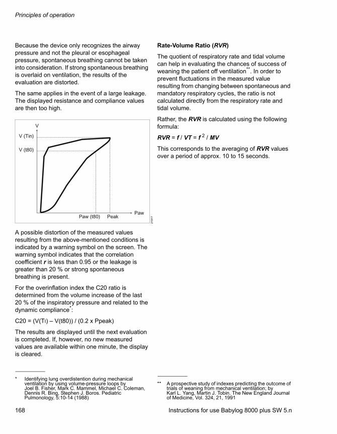
Principles of operation
168 Instructions for use Babylog 8000 plus SW 5.n
Because the device only recognizes the airway pressure and not the pleural or esophageal pressure, spontaneous breathing cannot be taken into consideration. If strong spontaneous breathing is overlaid on ventilation, the results of the evaluation are distorted.
The same applies in the event of a large leakage. The displayed resistance and compliance values are then too high.
A possible distortion of the measured values resulting from the above-mentioned conditions is indicated by a warning symbol on the screen. The warning symbol indicates that the correlation coefficient r is less than 0.95 or the leakage is greater than 20 % or strong spontaneous breathing is present.
For the overinflation index the C20 ratio is determined from the volume increase of the last 20 % of the inspiratory pressure and related to the dynamic compliance*:
C20 = (V(TI) – V(t80)) / (0.2 x Ppeak)
The results are displayed until the next evaluation is completed. If, however, no new measured values are available within one minute, the display is cleared.
Rate-Volume Ratio (RVR)
The quotient of respiratory rate and tidal volume can help in evaluating the chances of success of weaning the patient off ventilation**. In order to prevent fluctuations in the measured value resulting from changing between spontaneous and mandatory respiratory cycles, the ratio is not calculated directly from the respiratory rate and tidal volume.
Rather, the RVR is calculated using the following formula:
RVR = f / VT = f 2 / MV
This corresponds to the averaging of RVR values over a period of approx. 10 to 15 seconds.
21
91
7
* Identifying lung overdistention during mechanical ventilation by using volume-pressure loops by Joel B. Fisher, Mark C. Mammel, Michael C. Coleman, Dennis R. Bing, Stephen J. Boros. Pediatric Pulmonology, 5:10-14 (1988)
** A prospective study of indexes predicting the outcome of trials of weaning from mechanical ventilation; by Karl L. Yang, Martin J. Tobin. The New England Journal of Medicine, Vol. 324, 21, 1991
Instructions for use Babylog 8000 plus SW 5.n 169
Index
Index
A
Abbreviations . . . . . . . . . . . . . . . . . . . . . . . . . . .24Additional components
Safety information. . . . . . . . . . . . . . . . . . . . .43Airway pressure measurement. . . . . . . . . . . . .165Alarm limits . . . . . . . . . . . . . . . . . . . . . . . . . . . . .84
Checking. . . . . . . . . . . . . . . . . . . . . . . . . . . .59Deactivating . . . . . . . . . . . . . . . . . . . . . . . . .85Setting. . . . . . . . . . . . . . . . . . . . . . . . . . . . . .84
Alarm messageAcknowledging . . . . . . . . . . . . . . . . . . . . . . .83
Alarm priorities . . . . . . . . . . . . . . . . . . . . . . . . . .82Alarm signal
Setting volume . . . . . . . . . . . . . . . . . . . . . .100Suppressing . . . . . . . . . . . . . . . . . . . . . . . . .83
Alarm signalsAcoustic . . . . . . . . . . . . . . . . . . . . . . . . . . . .82Visual . . . . . . . . . . . . . . . . . . . . . . . . . . . . . .82
Alarm – Cause – Remedy . . . . . . . . . . . . . . . .106Alarms
Display . . . . . . . . . . . . . . . . . . . . . . . . . .32, 82Ambient conditions . . . . . . . . . . . . . . . . . . . . . .131Areas of use . . . . . . . . . . . . . . . . . . . . . . . . . . . .16
B
Bacterial filter . . . . . . . . . . . . . . . . . . . . . . . . . . .44Battery
Charging . . . . . . . . . . . . . . . . . . . . . . . . . . . .57Disposal . . . . . . . . . . . . . . . . . . . . . . . . . . .128
Breathing circuitChecking for leaks . . . . . . . . . . . . . . . . . . . .60Safety information. . . . . . . . . . . . . . . . . . . . .43
Breathing gas humidifier. . . . . . . . . . . . . . . . . . .43Breathing hoses
Attaching. . . . . . . . . . . . . . . . . . . . . . . . . . . .44Disconnecting . . . . . . . . . . . . . . . . . . . . . . . 113
C
Calibration intervals. . . . . . . . . . . . . . . . . . . . . . 93Compressed gas hoses
Connecting. . . . . . . . . . . . . . . . . . . . . . . . . . 49Removing. . . . . . . . . . . . . . . . . . . . . . . . . . . 80
Contrast. . . . . . . . . . . . . . . . . . . . . . . . . . . . . . 100Control and display unit
Overview . . . . . . . . . . . . . . . . . . . . . . . . . . . 19Control unit . . . . . . . . . . . . . . . . . . . . . . . . . . . . 29Cooling air filter
Replacing. . . . . . . . . . . . . . . . . . . . . . . . . . 126
D
DataOutput . . . . . . . . . . . . . . . . . . . . . . . . . . . . . 76
Data interfacesConfiguring . . . . . . . . . . . . . . . . . . . . . . . . 101
DateSetting . . . . . . . . . . . . . . . . . . . . . . . . . . . . . 99
Device checkAfter reprocessing . . . . . . . . . . . . . . . . . . . . 58Before use on a patient . . . . . . . . . . . . . . . . 60
Device combinations . . . . . . . . . . . . . . . . . . . . . . 9Device information
Displaying . . . . . . . . . . . . . . . . . . . . . . . . . . 99Device outputs. . . . . . . . . . . . . . . . . . . . . . . . . 141Dialog window
Alarm limits . . . . . . . . . . . . . . . . . . . . . . . . . 35Calibration . . . . . . . . . . . . . . . . . . . . . . . . . . 36Configuration . . . . . . . . . . . . . . . . . . . . . . . . 36Displays and logbook. . . . . . . . . . . . . . . . . . 35Layout . . . . . . . . . . . . . . . . . . . . . . . . . . . . . 33Opening . . . . . . . . . . . . . . . . . . . . . . . . . . . . 33Ventilation . . . . . . . . . . . . . . . . . . . . . . . . . . 34
Display unit . . . . . . . . . . . . . . . . . . . . . . . . . . . . 29

Index
170 Instructions for use Babylog 8000 plus SW 5.n
E
Electromagnetic compatibility . . . . . . . . . . . . . . . 10EMC Declaration . . . . . . . . . . . . . . . . . . . . . . . 146Endotracheal suction . . . . . . . . . . . . . . . . . . . . . 68Expiratory valve
Installing . . . . . . . . . . . . . . . . . . . . . . . . . . . . 42Removing . . . . . . . . . . . . . . . . . . . . . . . . . . 113
F
Flow measurement. . . . . . . . . . . . . . . . . . . . . . 165Flow monitoring
Activating . . . . . . . . . . . . . . . . . . . . . . . . . . . 97Deactivating . . . . . . . . . . . . . . . . . . . . . . . . . 96
Flow sensorAttaching. . . . . . . . . . . . . . . . . . . . . . . . . . . . 46Calibrating. . . . . . . . . . . . . . . . . . . . . . . . . . . 95Dismantling . . . . . . . . . . . . . . . . . . . . . . . . . 112Replacing insert . . . . . . . . . . . . . . . . . . . . . . 47
Flow sensor cableConnecting . . . . . . . . . . . . . . . . . . . . . . . . . . 46
Flow sensor insertInstalling . . . . . . . . . . . . . . . . . . . . . . . . . . . 119Replacing . . . . . . . . . . . . . . . . . . . . . . . . . . . 47
Flow triggerDescription . . . . . . . . . . . . . . . . . . . . . . . . . 166
Function description, pneumatic. . . . . . . . . . . . 153
G
Gas analyzer . . . . . . . . . . . . . . . . . . . . . . . . . . . 48Gas failure alarm
Checking. . . . . . . . . . . . . . . . . . . . . . . . . . . . 58Gas supply . . . . . . . . . . . . . . . . . . . . . . . . . . . . . 49Graphic Screen . . . . . . . . . . . . . . . . . . . . . . . . . 40
H
High-frequency ventilationDescription . . . . . . . . . . . . . . . . . . . . . . . . . 162Setting. . . . . . . . . . . . . . . . . . . . . . . . . . . . . . 67
I
Impulse outputConfiguring . . . . . . . . . . . . . . . . . . . . . . . . 103
InspirationManual . . . . . . . . . . . . . . . . . . . . . . . . . . . . . 69
Intended use . . . . . . . . . . . . . . . . . . . . . . . . . . . 16Interface
Analog and digital . . . . . . . . . . . . . . . . . . . . 76Configuring . . . . . . . . . . . . . . . . . . . . . . . . 104
IT networks . . . . . . . . . . . . . . . . . . . . . . . . . . . 151
L
LanguageSelecting . . . . . . . . . . . . . . . . . . . . . . . . . . 101
Leakage rateDescription. . . . . . . . . . . . . . . . . . . . . . . . . 166
LogbookDisplaying . . . . . . . . . . . . . . . . . . . . . . . . . . 91
Lung-mechanic parametersDescription. . . . . . . . . . . . . . . . . . . . . . . . . 167Displaying . . . . . . . . . . . . . . . . . . . . . . . . . . 88
M
Main screen. . . . . . . . . . . . . . . . . . . . . . . . . . . . 33Maintenance . . . . . . . . . . . . . . . . . . . . . . . . . . . . 8Manual inspiration . . . . . . . . . . . . . . . . . . . . . . . 69Measure values
Displaying . . . . . . . . . . . . . . . . . . . . . . . 87, 89Measurements. . . . . . . . . . . . . . . . . . . . . . . . . 165MEDIBUS protocol . . . . . . . . . . . . . . . . . . . . . . 51Medical device
Disposal . . . . . . . . . . . . . . . . . . . . . . . . . . . 128Medical devices
Classification . . . . . . . . . . . . . . . . . . . . . . . 114Medication nebulization. . . . . . . . . . . . . . . . . . . 70Medication nebulizer
Dismantling . . . . . . . . . . . . . . . . . . . . . . . . 112Monitor
Mounting . . . . . . . . . . . . . . . . . . . . . . . . . . . 40Monitoring functions . . . . . . . . . . . . . . . . . 23, 138
N
Non-critical medical devicesReprocessing. . . . . . . . . . . . . . . . . . . . . . . 114
Non-invasive ventilation . . . . . . . . . . . . . . . . . . 23

Instructions for use Babylog 8000 plus SW 5.n 171
Index
O
O2 sensorCalibrating. . . . . . . . . . . . . . . . . . . . . . . . . . .94Disposal . . . . . . . . . . . . . . . . . . . . . . . . . . .129Installing . . . . . . . . . . . . . . . . . . . . . . . . . . . .42Replacing . . . . . . . . . . . . . . . . . . . . . . . . . . .42
Operating data characteristics . . . . . . . . . . . . .139Operation
Terminating . . . . . . . . . . . . . . . . . . . . . . . . . .80
P
Patient connection panelOverview. . . . . . . . . . . . . . . . . . . . . . . . . . . .20
Patient monitorTransferring data. . . . . . . . . . . . . . . . . . . . . .79
Performance characteristics . . . . . . . . . . . . . . .133Pneumatic function description. . . . . . . . . . . . .153Potential equalization
Establishing . . . . . . . . . . . . . . . . . . . . . . . . .52Power failure. . . . . . . . . . . . . . . . . . . . . . . . . . . .85Power supply . . . . . . . . . . . . . . . . . . . . . . . . . . .50Power supply failure alarm
Checking alarm. . . . . . . . . . . . . . . . . . . . . . .58Pressure plateau
Setting. . . . . . . . . . . . . . . . . . . . . . . . . . . . . .64Preventive maintenance. . . . . . . . . . . . . . . . . .124Preventive maintenance intervals. . . . . . . . . . .124Printer
Configuring . . . . . . . . . . . . . . . . . . . . . . . . .104Product labels. . . . . . . . . . . . . . . . . . . . . . . . . . .27
R
Rate-Volume RatioDescription . . . . . . . . . . . . . . . . . . . . . . . . .168
Readiness for operationChecking. . . . . . . . . . . . . . . . . . . . . . . . . . . .58
RearOverview. . . . . . . . . . . . . . . . . . . . . . . . . . . .21
Repairs . . . . . . . . . . . . . . . . . . . . . . . . . . . . . . .125Report
Printing . . . . . . . . . . . . . . . . . . . . . . . . . . . . .78Reprocessing list . . . . . . . . . . . . . . . . . . . . . . . 117Reprocessing methods. . . . . . . . . . . . . . . . . . . 114
S
Safety checks . . . . . . . . . . . . . . . . . . . . . . . 8, 122Safety principle . . . . . . . . . . . . . . . . . . . . . . . . 145Sample line
Connecting. . . . . . . . . . . . . . . . . . . . . . . . . . 48Semi-critical medical devices
Reprocessing. . . . . . . . . . . . . . . . . . . . . . . 115Sensors . . . . . . . . . . . . . . . . . . . . . . . . . . . . . . . 93Separate expiratory flow
Description. . . . . . . . . . . . . . . . . . . . . . . . . 162Setting . . . . . . . . . . . . . . . . . . . . . . . . . . . . . 66
Set values . . . . . . . . . . . . . . . . . . . . . . . . . . . . 131Displaying . . . . . . . . . . . . . . . . . . . . . . . . . . 89
Setting knobs. . . . . . . . . . . . . . . . . . . . . . . . . . . 29Sterilization . . . . . . . . . . . . . . . . . . . . . . . . . . . 116Suction . . . . . . . . . . . . . . . . . . . . . . . . . . . . . . . 68Switching on . . . . . . . . . . . . . . . . . . . . . . . . . . . 55Symbols. . . . . . . . . . . . . . . . . . . . . . . . . . . . . . . 26
T
Test lungConnecting. . . . . . . . . . . . . . . . . . . . . . . . . . 47
TimeSetting . . . . . . . . . . . . . . . . . . . . . . . . . . . . . 99
TrendDisplaying . . . . . . . . . . . . . . . . . . . . . . . . . . 90Printing. . . . . . . . . . . . . . . . . . . . . . . . . . . . . 78
TriggerDisplay . . . . . . . . . . . . . . . . . . . . . . . . . . . . . 32
Trigger threshold . . . . . . . . . . . . . . . . . . . . . . . . 64Trolley
Overview . . . . . . . . . . . . . . . . . . . . . . . . . . . 22Preparation . . . . . . . . . . . . . . . . . . . . . . . . . 38
V
VentilationCPAP . . . . . . . . . . . . . . . . . . . . . . . . . . . . . . 65High-frequency . . . . . . . . . . . . . . . . . . . . . . 67Separate expiratory flow . . . . . . . . . . . 66, 162Setting . . . . . . . . . . . . . . . . . . . . . . . . . . . . . 63Starting. . . . . . . . . . . . . . . . . . . . . . . . . . . . . 56Volume Guarantee. . . . . . . . . . . . . . . . . . . . 66With pressure plateau . . . . . . . . . . . . . . . . . 64Without pressure plateau. . . . . . . . . . . . . . . 65
Ventilation functions . . . . . . . . . . . . . . . . . . . . . 23Checking . . . . . . . . . . . . . . . . . . . . . . . . . . . 60

Index
172 Instructions for use Babylog 8000 plus SW 5.n
Ventilation modeDescription . . . . . . . . . . . . . . . . . . . . . . . . . 156Setting. . . . . . . . . . . . . . . . . . . . . . . . . . . . . . 30
Ventilation parametersSetting. . . . . . . . . . . . . . . . . . . . . . . . . . . . . . 29
VentilatorDismantling . . . . . . . . . . . . . . . . . . . . . . . . . 111Preparation . . . . . . . . . . . . . . . . . . . . . . . . . . 42Switching off . . . . . . . . . . . . . . . . . . . . . . . . . 80Switching on . . . . . . . . . . . . . . . . . . . . . . . . . 55
Visual inspection . . . . . . . . . . . . . . . . . . . . . . . 116Volume . . . . . . . . . . . . . . . . . . . . . . . . . . . . . . . 100Volume Guarantee
Description . . . . . . . . . . . . . . . . . . . . . . . . . 161Setting. . . . . . . . . . . . . . . . . . . . . . . . . . . . . . 66
W
WaveformsDisplaying . . . . . . . . . . . . . . . . . . . . . . . . . . . 87Printing . . . . . . . . . . . . . . . . . . . . . . . . . . . . . 79
Y
Y-pieceAttaching. . . . . . . . . . . . . . . . . . . . . . . . . . . . 46

Instructions for use Babylog 8000 plus SW 5.n 173
This page intentionally left blank.
visi
on]_
000
002
4984
_No.
120
1
Á9028884öÈ
These instructions for use only apply to Babylog 8000 plus SW 5.nwith the Serial No.:If no serial number has been filled in by Dräger, these instructions for use are provided for general information only and are not intended for use with any specific medical device.These instructions for use are provided for customer information only and will only be updated or exchanged upon customer request.
Directive 93/42/EEC concerning medical devices
Manufacturer
Dräger Medical GmbHMoislinger Allee 53 – 55D-23542 LübeckGermany+49 451 8 82-0
FAX +49 451 8 82-2080http://www.draeger.com
As of 2015-08:Dräger Medical GmbHchanges toDrägerwerk AG & Co. KGaA
9028884 – GA 6173.320 en© Dräger Medical GmbHEdition: 8 – 2015-02(Edition: 1 – 1996-10)Dräger reserves the right to make modifications to the device without prior notice.