instructions for the installation and commissioning of
TRANSCRIPT

Instruction Booklet IB022018EN Effective July 2020
Instructions for the installation andcommissioning of Power Xpert TM
XGIS gas insulated switchgear

2
Instruction Booklet IB022018ENEffective July 2020
Instructions for the installation andcommissioning of Power XpertTM
XGIS gas insulated switchgear
EATON www.eaton.com

3
Instruction Booklet IB022018ENEffective July 2020
Instructions for the installation andcommissioning of Power XpertTM
XGIS gas insulated switchgear
EATON www.eaton.com
Disclaimer of warranties and limitation of liabilityThis instruction booklet is published solely for information purposes and should not be considered all-inclusive. If further information is required, you should consult an authorized Eaton sales representative.
The sale of the product shown in this literature is subject to the terms and conditions outlined in appropriate Eaton selling policies or other contractual agreement between the parties. This literature is not intended to and does not enlarge or add to any such contract. The sole source governing the rights and remedies of any purchaser of this equipment is the contract between the purchaser and Eaton.
NO WARRANTIES, EXPRESSED OR IMPLIED, INCLUDING WARRANTIES OF FITNESS FOR A PARTICULAR PURPOSE OR MERCHANTABILITY, OR WARRANTIES ARISING FROM THE COURSE OF DEALING OR USAGE OF TRADE, ARE MADE REGARDING THE INFORMATION, RECOMMENDATIONS, AND DESCRIPTIONS CONTAINED HEREIN.
In no event will Eaton be responsible to the purchaser or user in contract, in tort (including negligence), strict liability or otherwise for any special, indirect,incidental or consequential damage or loss whatsoever, including but not limited to damage or loss of use of equipment, plant or power system, cost of capital, loss of power, additional expenses in the use of existing power facilities, or claims against the purchaser or user by its customers resulting from the use of the information, recommendations and description contained herein.

4
Instruction Booklet IB022018ENEffective July 2020
Instructions for the installation andcommissioning of Power XpertTM
XGIS gas insulated switchgear
EATON www.eaton.com
ContentsSection 1: Introduction . . . . . . . . . . . . . . . . . . . . . . . . . . . . . . . . . . . . . . . . . . . . . . . . . . . . . . . . . . . . . . . . 7
1.1 Preliminary comments and safety precautions . . . . . . . . . . . . . . . . . . . . . . . . . . . . . . . . . . . . . . . . . . 71.1.1 Safety precautions . . . . . . . . . . . . . . . . . . . . . . . . . . . . . . . . . . . . . . . . . . . . . . . . . . . . . . . . . . . . 71.1.2 Switchgear identification . . . . . . . . . . . . . . . . . . . . . . . . . . . . . . . . . . . . . . . . . . . . . . . . . . . . . . . 7
1.2 General information . . . . . . . . . . . . . . . . . . . . . . . . . . . . . . . . . . . . . . . . . . . . . . . . . . . . . . . . . . . . . . 81.3 Power Xpert XGIS elements . . . . . . . . . . . . . . . . . . . . . . . . . . . . . . . . . . . . . . . . . . . . . . . . . . . . . . . 11
1.3.1 Standard features . . . . . . . . . . . . . . . . . . . . . . . . . . . . . . . . . . . . . . . . . . . . . . . . . . . . . . . . . . . 121.3.2 Ground bus . . . . . . . . . . . . . . . . . . . . . . . . . . . . . . . . . . . . . . . . . . . . . . . . . . . . . . . . . . . . . . . . 171.3.3 Bracing . . . . . . . . . . . . . . . . . . . . . . . . . . . . . . . . . . . . . . . . . . . . . . . . . . . . . . . . . . . . . . . . . . . 181.3.4 Arc resistant features . . . . . . . . . . . . . . . . . . . . . . . . . . . . . . . . . . . . . . . . . . . . . . . . . . . . . . . . 181.3.5 Optional features . . . . . . . . . . . . . . . . . . . . . . . . . . . . . . . . . . . . . . . . . . . . . . . . . . . . . . . . . . . . 181.3.6 XGIS vertical section configurations . . . . . . . . . . . . . . . . . . . . . . . . . . . . . . . . . . . . . . . . . . . . . 25
1.4 Type XGIS gas insulated switchgear ratings (tables 2, and 3) . . . . . . . . . . . . . . . . . . . . . . . . . . . . . 291.5 XGIS vertical section outlines and dimensions . . . . . . . . . . . . . . . . . . . . . . . . . . . . . . . . . . . . . . . . . 31
1.5.1 1250 A vertical section . . . . . . . . . . . . . . . . . . . . . . . . . . . . . . . . . . . . . . . . . . . . . . . . . . . . . . . . 311.5.2 2000 A / 2500 A vertical section . . . . . . . . . . . . . . . . . . . . . . . . . . . . . . . . . . . . . . . . . . . . . . . . 32
1.6 SSIS conductor system . . . . . . . . . . . . . . . . . . . . . . . . . . . . . . . . . . . . . . . . . . . . . . . . . . . . . . . . . . 331.6.1 SSIS bus in XGIS gas insulated switchgear . . . . . . . . . . . . . . . . . . . . . . . . . . . . . . . . . . . . . . . 331.6.2 Power cable conductors in XGIS switchgear . . . . . . . . . . . . . . . . . . . . . . . . . . . . . . . . . . . . . . 34
1.7 Voltage detection system . . . . . . . . . . . . . . . . . . . . . . . . . . . . . . . . . . . . . . . . . . . . . . . . . . . . . . . . . 361.7.1 Connecting the voltage detection system cables to ground . . . . . . . . . . . . . . . . . . . . . . . . . . . 36
Section 2: Safe practices . . . . . . . . . . . . . . . . . . . . . . . . . . . . . . . . . . . . . . . . . . . . . . . . . . . . . . . . . . . . . . 372.1 Recommendations . . . . . . . . . . . . . . . . . . . . . . . . . . . . . . . . . . . . . . . . . . . . . . . . . . . . . . . . . . . . . . 37
Section 3: Receiving, handling and storage . . . . . . . . . . . . . . . . . . . . . . . . . . . . . . . . . . . . . . . . . . . . . . . 383.1 General . . . . . . . . . . . . . . . . . . . . . . . . . . . . . . . . . . . . . . . . . . . . . . . . . . . . . . . . . . . . . . . . . . . . . . . 383.2 Receiving . . . . . . . . . . . . . . . . . . . . . . . . . . . . . . . . . . . . . . . . . . . . . . . . . . . . . . . . . . . . . . . . . . . . . 383.3 Handling . . . . . . . . . . . . . . . . . . . . . . . . . . . . . . . . . . . . . . . . . . . . . . . . . . . . . . . . . . . . . . . . . . . . . . 383.4 Unpacking . . . . . . . . . . . . . . . . . . . . . . . . . . . . . . . . . . . . . . . . . . . . . . . . . . . . . . . . . . . . . . . . . . . . . 383.5 Lifting vertical sections. . . . . . . . . . . . . . . . . . . . . . . . . . . . . . . . . . . . . . . . . . . . . . . . . . . . . . . . . . . 38
3.5.1 Lifting brackets attachment . . . . . . . . . . . . . . . . . . . . . . . . . . . . . . . . . . . . . . . . . . . . . . . . . . . 383.5.2 Lifting . . . . . . . . . . . . . . . . . . . . . . . . . . . . . . . . . . . . . . . . . . . . . . . . . . . . . . . . . . . . . . . . . . . . 39
3.6 Storage . . . . . . . . . . . . . . . . . . . . . . . . . . . . . . . . . . . . . . . . . . . . . . . . . . . . . . . . . . . . . . . . . . . . . . . 393.7 Tools and accessories . . . . . . . . . . . . . . . . . . . . . . . . . . . . . . . . . . . . . . . . . . . . . . . . . . . . . . . . . . . . 393.8 XGIS gas insulated switchgear vertical section weights . . . . . . . . . . . . . . . . . . . . . . . . . . . . . . . . . 39
Section 4: Initial inspection . . . . . . . . . . . . . . . . . . . . . . . . . . . . . . . . . . . . . . . . . . . . . . . . . . . . . . . . . . . . 40Section 5: Installation . . . . . . . . . . . . . . . . . . . . . . . . . . . . . . . . . . . . . . . . . . . . . . . . . . . . . . . . . . . . . . . . 41
5.1 Qualified personnel . . . . . . . . . . . . . . . . . . . . . . . . . . . . . . . . . . . . . . . . . . . . . . . . . . . . . . . . . . . . . 415.2 General field installation requirements . . . . . . . . . . . . . . . . . . . . . . . . . . . . . . . . . . . . . . . . . . . . . . 415.3 Installation requirements . . . . . . . . . . . . . . . . . . . . . . . . . . . . . . . . . . . . . . . . . . . . . . . . . . . . . . . . . 415.4 Typical floor plan and minimum recommended clearances . . . . . . . . . . . . . . . . . . . . . . . . . . . . . . . 415.5 Vertical section ceiling height requirements . . . . . . . . . . . . . . . . . . . . . . . . . . . . . . . . . . . . . . . . . . 415.6 Field installation precautions . . . . . . . . . . . . . . . . . . . . . . . . . . . . . . . . . . . . . . . . . . . . . . . . . . . . . . 45
5.6.1 Bolt tightening torques . . . . . . . . . . . . . . . . . . . . . . . . . . . . . . . . . . . . . . . . . . . . . . . . . . . . . . . 455.6.2 Handling of ssis silicone rubber insulator parts . . . . . . . . . . . . . . . . . . . . . . . . . . . . . . . . . . . . 45
5.7 Assembly . . . . . . . . . . . . . . . . . . . . . . . . . . . . . . . . . . . . . . . . . . . . . . . . . . . . . . . . . . . . . . . . . . . . . 455.7.1 Drawings . . . . . . . . . . . . . . . . . . . . . . . . . . . . . . . . . . . . . . . . . . . . . . . . . . . . . . . . . . . . . . . . . . 455.7.2 Assembly instructions . . . . . . . . . . . . . . . . . . . . . . . . . . . . . . . . . . . . . . . . . . . . . . . . . . . . . . . . 45
5.8 Low voltage control connections . . . . . . . . . . . . . . . . . . . . . . . . . . . . . . . . . . . . . . . . . . . . . . . . . . . 505.8.1 Auxiliary circuits available to the user . . . . . . . . . . . . . . . . . . . . . . . . . . . . . . . . . . . . . . . . . . . 505.9.1 SSIS bus installation in XGIS gas insulated switchgear . . . . . . . . . . . . . . . . . . . . . . . . . . . . . 515.9.2 Field installation precautions . . . . . . . . . . . . . . . . . . . . . . . . . . . . . . . . . . . . . . . . . . . . . . . . . . 52
5.10 Installing the bus and bushing . . . . . . . . . . . . . . . . . . . . . . . . . . . . . . . . . . . . . . . . . . . . . . . . . . . . 525.11 Low-voltage control cables . . . . . . . . . . . . . . . . . . . . . . . . . . . . . . . . . . . . . . . . . . . . . . . . . . . . . . . 55

5
Instruction Booklet IB022018ENEffective July 2020
Instructions for the installation andcommissioning of Power XpertTM
XGIS gas insulated switchgear
EATON www.eaton.com
5.12 Installing cable adapters . . . . . . . . . . . . . . . . . . . . . . . . . . . . . . . . . . . . . . . . . . . . . . . . . . . . . . . . . 575.13 Installing current transformers . . . . . . . . . . . . . . . . . . . . . . . . . . . . . . . . . . . . . . . . . . . . . . . . . . . . 58
5.13.1 Main bus compartment CTs . . . . . . . . . . . . . . . . . . . . . . . . . . . . . . . . . . . . . . . . . . . . . . . . . . 585.13.2 Cable side CTs . . . . . . . . . . . . . . . . . . . . . . . . . . . . . . . . . . . . . . . . . . . . . . . . . . . . . . . . . . . . 585.13.3 Installing CTs on main bus or cable side applications . . . . . . . . . . . . . . . . . . . . . . . . . . . . . . 605.13.4 Un-installing CTs on main bus or cable side applications. . . . . . . . . . . . . . . . . . . . . . . . . . . . 61
5.14 Voltage transformer installation and removal . . . . . . . . . . . . . . . . . . . . . . . . . . . . . . . . . . . . . . . . . 625.14.1 VT lifting truck . . . . . . . . . . . . . . . . . . . . . . . . . . . . . . . . . . . . . . . . . . . . . . . . . . . . . . . . . . . . . 625.14.2 Voltage transformer installation . . . . . . . . . . . . . . . . . . . . . . . . . . . . . . . . . . . . . . . . . . . . . . . 645.14.3 Voltage transformer removal . . . . . . . . . . . . . . . . . . . . . . . . . . . . . . . . . . . . . . . . . . . . . . . . . . 665.14.4 Fused voltage transformer fuse replacement . . . . . . . . . . . . . . . . . . . . . . . . . . . . . . . . . . . . 66
5.15 Auxiliary cabinet installation . . . . . . . . . . . . . . . . . . . . . . . . . . . . . . . . . . . . . . . . . . . . . . . . . . . . . . 68Section 6: Commissioning . . . . . . . . . . . . . . . . . . . . . . . . . . . . . . . . . . . . . . . . . . . . . . . . . . . . . . . . . . . . . 71
6.1 Pre-commissioning final inspection . . . . . . . . . . . . . . . . . . . . . . . . . . . . . . . . . . . . . . . . . . . . . . . . . 716.2 Commissioning procedures . . . . . . . . . . . . . . . . . . . . . . . . . . . . . . . . . . . . . . . . . . . . . . . . . . . . . . . 71
6.2.1 Preparations for commissioning . . . . . . . . . . . . . . . . . . . . . . . . . . . . . . . . . . . . . . . . . . . . . . . . 716.2.2 Startup . . . . . . . . . . . . . . . . . . . . . . . . . . . . . . . . . . . . . . . . . . . . . . . . . . . . . . . . . . . . . . . . . . . 71
Section 7: Testing . . . . . . . . . . . . . . . . . . . . . . . . . . . . . . . . . . . . . . . . . . . . . . . . . . . . . . . . . . . . . . . . . . . 727.1 Typical tests . . . . . . . . . . . . . . . . . . . . . . . . . . . . . . . . . . . . . . . . . . . . . . . . . . . . . . . . . . . . . . . . . . . 727.2 Voltage test . . . . . . . . . . . . . . . . . . . . . . . . . . . . . . . . . . . . . . . . . . . . . . . . . . . . . . . . . . . . . . . . . . . 72
7.2.1 Preparation for voltage withstand test . . . . . . . . . . . . . . . . . . . . . . . . . . . . . . . . . . . . . . . . . . . . 727.2.2 Performing switchgear voltage test . . . . . . . . . . . . . . . . . . . . . . . . . . . . . . . . . . . . . . . . . . . . . . 737.2.3 Performing cable voltage test . . . . . . . . . . . . . . . . . . . . . . . . . . . . . . . . . . . . . . . . . . . . . . . . . . 73
7.3 Current test . . . . . . . . . . . . . . . . . . . . . . . . . . . . . . . . . . . . . . . . . . . . . . . . . . . . . . . . . . . . . . . . . . . . 73Appendices . . . . . . . . . . . . . . . . . . . . . . . . . . . . . . . . . . . . . . . . . . . . . . . . . . . . . . . . . . . . . . . . . . . . . . . . 74
Appendix A - XGIS switchgear commissioning checklist . . . . . . . . . . . . . . . . . . . . . . . . . . . . . . . . . . . . 75
List of TablesTable 1. 3PDS status display table . . . . . . . . . . . . . . . . . . . . . . . . . . . . . . . . . . . . . . . . . . . . . . . . . . . . .16
Table 2. Vertical section dimensions . . . . . . . . . . . . . . . . . . . . . . . . . . . . . . . . . . . . . . . . . . . . . . . . . . . .29
Table 3. Electrical data. . . . . . . . . . . . . . . . . . . . . . . . . . . . . . . . . . . . . . . . . . . . . . . . . . . . . . . . . . . . . . .29
Table 4. Relevant standards . . . . . . . . . . . . . . . . . . . . . . . . . . . . . . . . . . . . . . . . . . . . . . . . . . . . . . . . . .30
Table 5. Operating conditions . . . . . . . . . . . . . . . . . . . . . . . . . . . . . . . . . . . . . . . . . . . . . . . . . . . . . . . . .30
Table 6. VDS LCD display performance. . . . . . . . . . . . . . . . . . . . . . . . . . . . . . . . . . . . . . . . . . . . . . . . . .36
Table 7. VDS relay output performance. . . . . . . . . . . . . . . . . . . . . . . . . . . . . . . . . . . . . . . . . . . . . . . . . .36
Table 8. Approximate vertical section weights (see exclusions above). . . . . . . . . . . . . . . . . . . . . . . . . .39
Table 9. XGIS bolt tightening specifications . . . . . . . . . . . . . . . . . . . . . . . . . . . . . . . . . . . . . . . . . . . . . .45
Table 10. Silicone grease application guide. . . . . . . . . . . . . . . . . . . . . . . . . . . . . . . . . . . . . . . . . . . . . . . .45
Table 11. SSIS bus and joints silicone grease application guide . . . . . . . . . . . . . . . . . . . . . . . . . . . . . . . .52
Table 12. Main bus cone centerline distances . . . . . . . . . . . . . . . . . . . . . . . . . . . . . . . . . . . . . . . . . . . . .52
Table 13. Top VT installation tool components . . . . . . . . . . . . . . . . . . . . . . . . . . . . . . . . . . . . . . . . . . . . .64

6
Instruction Booklet IB022018ENEffective July 2020
Instructions for the installation andcommissioning of Power XpertTM
XGIS gas insulated switchgear
EATON www.eaton.com
Read and understand these instructions before attempting installation, operation, or maintenance of this equipment. This equipment must be installed and serviced only by qualified electrical personnel. Retain this document for future use.
m WARNINGIMPROPERLY INSTALLING OR MAINTAINING THESE PRODUCTS CAN RESULT IN DEATH, SERIOUS PERSONAL INJURY, OR PROPERTY DAMAGE. READ AND UNDERSTAND THESE INSTRUCTIONS BEFORE ATTEMPTING ANY UNPACKING, ASSEMBLY, OPERATION OR MAINTENANCE OF THE CIRCUIT BREAKERS. INSTALLATION OR MAINTENANCE SHOULD BE ATTEMPTED ONLY BY QUALIFIED PERSONNEL. THIS INSTRUCTION BOOK SHOULD NOT BE CONSIDERED ALL INCLUSIVE REGARDING INSTALLATION OR MAINTENANCE PROCEDURES. IF FURTHER INFORMATION IS REQUIRED, YOU SHOULD CONTACT EATON.
m WARNINGDO NOT ATTEMPT ANY WORK ON THIS EQUIPMENT SUCH AS INSTALLING COMPONENTS, PERFORMING ANY EXAMINATIONS, PERFORMING ANY ADJUSTMENTS, PERFORMING ANY SERVICING, OR PERFORMING ANY MAINTENANCE WHILE IT IS ENERGIZED. BEFORE PERFORMING ANY WORK, FOLLOW ALL APPROPRIATE HAZARD ASSESSMENT AND ENERGY CONTROL PRECAUTIONS AND PROCEDURES. VERIFY NO VOLTAGES ARE PRESENT ON ALL INCOMING AND OUTGOING CONDUCTORS, AND ANY ENERGY SOURCES CONTAINED WITHIN THE EQUIPMENT PRIOR TO SERVICING, THEN GROUND (CONNECT TO EARTH) ALL INCOMING AND OUTGOING CONDUCTORS ATTACHED TO THIS EQUIPMENT AND TO ANY INTERNAL ENERGY SOURCES.
All possible contingencies which may arise during installation, operation or maintenance, and all details and variations of this equipment do not purport to be covered by these instructions. If further information is desired by purchaser regarding his particular installation, operation or maintenance of particular equipment, contact an Eaton representative.

7
Instruction Booklet IB022018ENEffective July 2020
Instructions for the installation andcommissioning of Power XpertTM
XGIS gas insulated switchgear
EATON www.eaton.com
Section 1: Introduction
1.1 Preliminary comments and safety precautions
This technical document is intended to cover most aspects associated with the installation and commissioning of Power XpertTM XGIS gas insulated switchgear. It is provided as a guide for authorized and qualified personnel only. Please refer to the specific WARNING messages in paragraph 1.1.2 before proceeding past Section 1. If further information is required regarding a particular installation, application or maintenance activity, an Eaton representative should be contacted.
1.1.1 Safety precautions
All safety codes, safety standards and/or regulations must be strictly observed in the installation, operation and maintenance of this device.
m WARNINGTHE WARNINGS AND CAUTIONS INCLUDED AS PART OF THE PROCEDURAL STEPS IN THIS DOCUMENT ARE FOR PERSONNEL SAFETY AND PROTECTION OF EQUIPMENT FROM DAMAGE. AN EXAMPLE OF A TYPICAL WARNING LABEL HEADING IS SHOWN ABOVE TO FAMILIARIZE PERSONNEL WITH THE STYLE OF PRESENTATION. THIS WILL HELP TO ENSURE THAT PERSONNEL ARE ALERT TO WARNINGS, WHICH MAY APPEAR THROUGHOUT THE DOCUMENT. IN ADDITION, CAUTIONS ARE ALL UPPER CASE AND BOLDFACE AS SHOWN BELOW.
m WARNINGCOMPLETELY READ AND UNDERSTAND THE MATERIAL PRESENTED IN THIS DOCUMENT BEFORE ATTEMPTING INSTALLATION, OPERATION OR APPLICATION OF THE EQUIPMENT. IN ADDITION, ONLY QUALIFIED PERSONS SHOULD BE PERMITTED TO PERFORM ANY WORK ASSOCIATED WITH THE EQUIPMENT. ANY WIRING INSTRUCTIONS PRESENTED IN THIS DOCUMENT MUST BE FOLLOWED PRECISELY. FAILURE TO DO SO COULD CAUSE PERMANENT EQUIPMENT DAMAGE, BODILY INJURY OR DEATH.
m WARNINGTHE POWER XPERT XGIS SWITCHGEAR DESCRIBED IN THIS DOCUMENT ARE DESIGNED AND TESTED TO OPERATE WITHIN ITS NAMEPLATE RATINGS. OPERATION OUTSIDE OF THESE RATINGS MAY CAUSE THE EQUIPMENT TO FAIL, RESULTING IN DEATH, BODILY INJURY AND PROPERTY DAMAGE. ALL SAFETY CODES, SAFETY STANDARDS AND/OR REGULATIONS AS THEY MAY BE APPLIED TO THIS TYPE OF EQUIPMENT MUST BE STRICTLY ADHERED TO.
1.1.2 Switchgear identification
A nameplate is located on the exterior door of each XGIS switchgear vertical section. Contained on this nameplate are the general order number, manufacturing shop order number, and all the necessary switchgear ratings. This information should be given to the Eaton sales office if a question should arise concerning the switchgear or if renewal parts are required. This information is sufficient for Eaton to find the manufacturing information for the switchgear.

8
Instruction Booklet IB022018ENEffective July 2020
Instructions for the installation andcommissioning of Power XpertTM
XGIS gas insulated switchgear
EATON www.eaton.com
1.2 General information
The purpose for this document is to provide instructions for unpacking, storage, installation, and commissioning of Power Xpert XGIS gas insulated switchgear (referred to as Type XGIS gas insulated switchgear from this point forward). These switchgear vertical sections employ state-of-the-art gas insulation, shielded solid insulation, vacuum interrupters, and modular plug-in technologies. Combined with laser welding technology and a helium gas leakage testing process, this system provides high reliability and a small installation footprint. They provide reliable control and protection for electrical equipment and circuits, up to 38 kV.
XGIS switchgear is designed for reliable performance, ease of handling and simplified maintenance. In addition, XGIS switchgear is tested to IEC standards for application around the world.
The XGIS switchgear has been tested to the seismic requirements contained in the IEEE 693 standard, the International Building Code (IBC 2015), and the California Building Code (CBC 2016). For more information, refer to Seismic Certificate Number SA022006EN.
XGIS gas insulated switchgear vertical sections incorporate technology intended to make the XGIS system smaller in size, easier to install, more reliable and easier to maintain than air-insulated switchgear.
XGIS vertical sections come in five configurations. Options are available to customize the equipment for each application. The five configurations are • Feeder/incoming• Bus tie• Bus sectionalizer• Disconnector• Cable connector
The XGIS switchgear vertical sections come with standard and optional features. All of the vertical sections include a pressurized tank filled with SF6, (sulfur hexafluoride).
All XGIS vertical sections are designed for bottom entry of the power cables. All XGIS vertical sections are designed for top or bottom entry of low-voltage power and control wiring.
An option of the XGIS design is available that is certified to IP4X requirements.
The XGIS design is not rated for outdoor service.
Figure 1 shows an XGIS vertical section exterior with its primary elements. Figure 2 shows the details of the medium voltage power components and control elements.
Figure 3 and Figure 4 show XGIS system power components for a 1250 A standard section and a 1250 A bus tie section.
Figure 5 shows an XGIS vertical section with front and interior control components.
Figure 1.
Low VoltageWireway
(Top)
ControlCompartment
Access Door
Cable / Bus TieCompartmentAccess Cover
Main Bus Compartment
RearArc ReliefCompartment
Top VT / Arc ReliefCompartment
Ground Bus Link
XGIS exterior.
Figure 2. XGIS interior and control elements.

9
Instruction Booklet IB022018ENEffective July 2020
Instructions for the installation andcommissioning of Power XpertTM
XGIS gas insulated switchgear
EATON www.eaton.com
Figure 3. XGIS
Main BusCompartment
Top VT / Arc Relief
Compartment
Fused VT
VTEarthingSwitch
MainBus Joints
Low VoltageControl
Compartment
Low VoltageWireway
(Top)
Tank GasPressure Gauge
3PDSOperator
VacuumCircuit Breaker
Mechanism
VacuumCircuit Breaker
3PDS
CableCompartment
CableTee
Connectors
CableClampBraces
CableCTs
TankOverpressure
Relief
RearArc Relief
Compartment
SF6 Tank
3PDS = Three Position Disconnect Switch
VT EarthingSwitch
Operator
1250 A cable connection section, side view

10
Instruction Booklet IB022018ENEffective July 2020
Instructions for the installation andcommissioning of Power XpertTM
XGIS gas insulated switchgear
EATON www.eaton.com
Figure 4.
Main BusCompartment
Top VT / Arc Relief
Compartment
Fused VT
VTEarthingSwitch
MainBus Joints
Low VoltageControl
Compartment
Low VoltageWireway
(Top)
Tank GasPressure Gauge
3PDSOperator
VacuumCircuit Breaker
MechanismVacuum
Circuit Breaker
3PDS
Bus TieCompartment
TieBus Joints
VT EarthingSwitch
Operator
SF6 Tank
3PDS = Three Position Disconnect Switch
TankOverpressure
Relief
RearArc Relief
Compartment
XGIS 1250 A bus tie section, side view

11
Instruction Booklet IB022018ENEffective July 2020
Instructions for the installation andcommissioning of Power XpertTM
XGIS gas insulated switchgear
EATON www.eaton.com
1.3 Power Xpert XGIS elements
Figure 5.
Low-voltage compartment
Low-voltage panel
Tankpressure gauge
Disconnect switch
operator
VT earthingswitch
operator
Circuit breaker
Cable terminations
Three positiondisconnect switch
View port
Three position disconnect switchcontrol pushbuttons
Circuit breaker statusindicating lights
Circuit breakercontrol switch
Three position disconnect switchindicating lights
Meters and relays
Circuit breakerstatus viewingwindow
Voltage DetectionSystem
Three positiondisconnect switchposition viewing window
Tank pressuregauge viewingwindow
Cable bracing
Ground bus
XGIS front and interior control components.

12
Instruction Booklet IB022018ENEffective July 2020
Instructions for the installation andcommissioning of Power XpertTM
XGIS gas insulated switchgear
EATON www.eaton.com
1.3.1 Standard features
XGIS switchgear includes a three-position disconnect switch (3PDS) for circuit isolation, and a vacuum interrupter circuit breaker.
The 3PDS and circuit breaker can each be operated electrically or manually. The circuit breaker can be charged, closed or opened locally or remotely. The circuit breaker trip operation is initiated by external protective relays or other control devices. The 3PDS is interlocked with the circuit breaker.
SF6 gas as an insulating medium
Sulfur Hexafluoride is an odorless, colorless, inert, non-toxic, non-corrosive and non-flammable gas. It is thermally stable and must be heated to more than 500º Celsius (932º F) before it will decompose. The symmetry of the atoms in its molecular structure makes it extremely stable, with a very high dielectric strength. Its dielectric capability is approximated three times that of air at atmospheric pressure. This means that equipment insulated with SF6 can be much more compact than air-insulated equipment.
Power Xpert XGIS vertical section characteristics
An XGIS vertical section is divided into two functional areas: low- and medium-voltage.
1.3.1.1 Low-voltage area
The XGIS vertical section front door is used to access the low-voltage section. This section houses low-voltage control and operating mechanisms for the three position disconnect switch (3PDS) and vacuum interrupter circuit breaker.
The vertical section door has control devices mounted on it for:• Circuit breaker open/closed switch and status indicating lights.• 3PDS status indicator lights and pushbuttons for 3PDS ground,
open, and close operations.• 3PDS (grounding function) status indicators and pushbuttons for
3PDS grounding open and close.• Customer specific control devices.• Customer specific protective device(s).
The XGIS switchgear 3PDS operating mechanism is mounted on the gas tank front panel, located below the low-voltage control area. It is mechanically coupled to the 3PDS through a gas-tight tank fitting. It has electrical and manual modes of operation. It is mechanically and electrically interlocked with the circuit breaker to assure that the breaker is open prior to operation of the 3PDS for closing, isolation, or grounding.
The operating mechanism includes a rotary cam limit switch array, linkages for manual operation, and mechanical front panel switch status indicators. The motor propels a chain drive that moves the 3PDS from one position (closed, open, or grounded) to another. The cam and limit switches provide positive 3PDS position feedback to the operating mechanism.
The 3PDS normal operation mode is electric, but it also has a front access cover for manual operation.
Three position disconnect switch manual operation is performed by opening the manual mode access cover when the circuit breaker is open, inserting a tool and rotating the recessed socket. Turning the manual operation socket with the manual operation tool moves the switch connector smoothly through each position. The three position disconnect switch has a clutch that slips when the switch reaches the next position. The tool must then be removed and reinserted to continue moving the switch to the next position.
The vacuum interrupter circuit breaker operating mechanism is also mounted on the gas tank front panel, below the three position disconnect switch’s operating mechanism. The circuit breaker mechanism includes stored energy springs for breaker closing and opening. The springs are charged either by an electric drive (normal mode) or using a manual charging handle mounted in the circuit breaker operating mechanism front cover.
The circuit breaker operating mechanism includes mechanical indicators for spring charged/discharged status and circuit breaker open/closed status. These indicators are visible through cutouts in the circuit breaker mechanism front cover.
The circuit breaker can be operated mechanically by buttons located on its front cover or electrically by pushbuttons mounted on the vertical section door, or remotely.
The three position disconnect switch and circuit breaker are both mechanically and electrically interlocked to prevent improper operation during normal (electrical) and manual (mechanical) operation.
Low-voltage control wiring is routed from the internal vertical section terminal boards to an Eaton blue colored top hat, above the low-voltage compartment. Control wiring from vertical section to vertical section in a lineup is routed through these top hats.
SF6 tank gauge
The SF6 tank has a pressure gauge mounted on the tank upper left front face, with a color-coded scale indicating safe, caution and danger pressure values. In addition, the gauge includes pressure sensors with three contact outputs, 1.3 bar absolute (Normal), 1.2 bar (Alarm) and 1.1 bar (Block).
Figure 6. Tank pressure gauge.
SF6 Tank filling fitting
To the right of the tank pressure gauge, a second pressure fitting is available for filling and evacuating the tank.
Figure 7. Tank filling fitting.
SF6 3PDS position viewing port
To the right of the tank charging fitting, a viewing port is available to observe the 3PDS position. This port is available for mounting a camera if desired.

13
Instruction Booklet IB022018ENEffective July 2020
Instructions for the installation andcommissioning of Power XpertTM
XGIS gas insulated switchgear
EATON www.eaton.com
Figure 8. Tank viewing port.
The camera port provides a view of all three of the 3PDS mechanisms, and shows the ground, open and closed positions and armature poles. Figure 6 shows view port images of all three disconnect switch poles.
Figure 9. 3PDS pole positions viewed at port. Images are enhanced for clarity.
Circuit breaker cycle counter
The 1250 A XGIS circuit breaker is rated for 10,000 load or no-load operations. The 2000 A and 2500 A XGIS circuit breakers are rated for 2,000 load or no load operations. Each closing spring charging operation is recorded on the cycle counter mounted on the left side of the circuit breaker frame, and viewable through a window in the front cover.
Figure 10. Circuit breaker cycle counter.
1.3.1.2 Medium-voltage area
SSIS conductor system
Power input and output circuits between XGIS vertical sections are connected to the XGIS using shielded solid insulation system (SSIS) conductor and termination elements. These elements are designed for medium voltage application and provide excellent insulation and current carrying features when properly installed using their mating bus joints.
Figure 11. Main bus joint cones (SSIS).
The outer layer of each insulating component of the SSIS conductor system is shielded and grounded to the tank. The entire exterior of the SSIS conductor is at ground potential when properly installed.
Gas tank
Behind the low-voltage panel and above the output cable compartment, the gas tank is the heart of the XGIS switchgear. The tank is pressurized to slightly over atmospheric pressure with SF6 gas, to insulate the MV components inside the tank.

14
Instruction Booklet IB022018ENEffective July 2020
Instructions for the installation andcommissioning of Power XpertTM
XGIS gas insulated switchgear
EATON www.eaton.com
The tanks are laser-welded to be gas tight. They have bushings on their top surface for main bus connections. Tanks for cable connections have bushings on the bottom front tank surface. Tanks for bus tie connections have bushings on the tank bottom surface. These bushings accommodate connections for main bus, cables or sectionalizing bus. The tank faces have gasketed ports for 3PDS and circuit breaker mechanical drive mounting. If repairs are needed, a rear access panel can be removed to access the devices inside the tank. If repairs inside the tank are required, an Eaton service repre-sentative should be contacted.
The gas tank includes a front fitting and gauge for gas pressure monitoring, and another front fitting for filling or evacuating the tank. Both fittings are viewable in the low-voltage area, below the low-volt-age control DIN rails and wire channels.
A viewing port is mounted on the gas tank front face, beside the tank pressure gauge and charging fitting, for viewing the 3PDS position. This port can be fitted for a mounted camera. From there the 3PDS open, ground and closed positions can be seen.
The tank has an overpressure relief fitting mounted on the lower part of the tank rear vertical face. The overpressure relief fitting will rupture at 2 bar absolute.
For the 2000 A and 2500 A vertical section designs, a heat sink assembly is mounted on the rear of the tank, with fins extending out into the back portion of the vertical section. This heat sink provides additional cooling for the busbar connections within the tank.
Figure 12. Tank heatsink assembly for 2000 A / 2500 A vertical section.
Medium-voltage connections
The gas tank top has bushings for interface with main SSIS busbars. The main horizontal bus conductors can be fitted with optional CTs.
The gas tank lower front surface has bushings for output conductors, connecting either power cables or SSIS busbar, and can be fitted with optional CTs.
Conductors connecting the input bushings to the three-position disconnect switch (3PDS) are contained within the gas tank. When the switchgear is furnished with a 3PDS only, conductors from the 3PDS output terminals to the output bushings are contained within the tank. Since the 3PDS are not interlocked with other panels, it is recommended that access to the 3PDS panel and tie breaker panels be controlled and restricted using a Kirk key, padlock, or similar lockout system, so that only trained personnel can access them.
When a vacuum circuit breaker is furnished in the vertical section, the 3PDS is mounted and connected to the top of the circuit breaker assembly in the tank, and conductors run from the breaker’s output terminals to the tank output bushings.
Three position disconnect switch
XGIS switchgear includes a three-pole medium-voltage three-posi-tion disconnect switch (3PDS) in the tank. Each phase pole consists of a piston on a screw drive. This linear travel device is mechanically coupled to its operating mechanism through the tank wall. In the closed position, the 3PDS connects each phase of the main bus to incoming/outgoing power, through the vacuum circuit breaker (if furnished). If opened, the 3PDS disconnects each phase of the main bus from the incoming/outgoing power. If grounded, the three position disconnector switch grounds the incoming/outgoing power through the vacuum circuit breaker (if furnished).
The grounded and closed (connected) position contacts are sockets, electrically connected respectively to the vertical section ground bus and to the incoming power bus. A center socket between the ground and main bus sockets is connected to the circuit breaker. The screw-driven connection piston moves to connect the circuit breaker to either ground or main bus. When the piston is not connected to either the grounded position or the closed position, but rests entirely within the circuit breaker connection socket, the 3PDS is in the open position, isolating the circuit breaker from the main bus or ground.
The 3PDS mechanical drive consists of a gear reduction, a chain drive and three sprockets. Each sprocket turns an output shaft, connected to a pole screw.
The 3PDS is a non-load break device, intended to connect down-stream elements to the input source only under no-load (open circuit) conditions.
Figure 13. Three position disconnect switch (3PDS).
The 3PDS poles are propelled by screw drives, one for each pole. Normally the screws are driven by a dc motor. The gear output shafts which turn the pole screws pass through tank wall magnetic fluid seals.
Power and control for the 3PDS dc motor are provided by a dedi-cated controller mounted on the low-voltage panel.
The 3PDS has a second, mechanical drive means. If desired, a manual operation door in the front of the 3PDS operating mecha-nism can be opened to allow a T-handle to be inserted and turned to operate the screw drive. See the T-handle in Figure 14.

15
Instruction Booklet IB022018ENEffective July 2020
Instructions for the installation andcommissioning of Power XpertTM
XGIS gas insulated switchgear
EATON www.eaton.com
Figure 14. 3PDS manual operation T-handle.
NOTICEDURING MANUAL OPERATION, THE THREE POSITION DISCONNECT SWITCH HAS NO SCREW DRIVE TRAVEL MECHANICAL LIMITS. IT CAN BE MOVED INTO OVERTRAVEL POSITIONS AT BOTH ENDS OF TRAVEL (GROUND AND CLOSED). DO NOT MOVE THE SCREW DRIVE BEYOND ITS END OF TRAVEL INDICATIONS, AS THAT CAN RESULT IN DAMAGE TO THE SCREW DRIVE MECHANISM. USE THE THREE POSITION DISCONNECT SWITCH STATUS DISPLAY WINDOWS TO DETERMINE WHEN THE THREE POSITION DISCONNECT SWITCH HAS REACHED THE DESIRED LOCATION.
Figure 15. Disconnect switch windows and label.
In order to ground the output cables or coupling bus, the 3PDS must be put in the ground position and the circuit breaker must be closed.
The 3PDS screw drive also propels a cam limit switch mounted inside the operating mechanism. This cam limit switch has four contacts. The contacts are used in the electric control system to signal 3PDS status: closed, opened and grounded.
The 3PDS and circuit breaker are mechanically and electrically interlocked to prevent inappropriate operation.
Figure 16. 3PDS chain drive.
A mechanical display provided on front of the 3PDS operating mechanism face plate indicates the switch position status as shown in Figure 17.
Figure 17. 3PDS (normal operation).

16
Instruction Booklet IB022018ENEffective July 2020
Instructions for the installation andcommissioning of Power XpertTM
XGIS gas insulated switchgear
EATON www.eaton.com
Figure 18. 3PDS (manual operation).
The 3PDS mechanical status display uses symbols to indicate switch position. The display windows show the switch in its proper positions only when the symbols are in the center of their windows. See Figure 17. Refer to Table 1 for disconnect position associated with I and O symbols displayed in the status windows.
Table 1. 3PDS status display table
3PDS position
Ground 1 0Open 0 0Closed 0 1
The 3PDS comes standard with locking means to prevent closing the switch or grounding the switch. These locking features consist of brackets for padlocks and Kirk lock fittings. Each bracket, whether for preventing closing or for preventing grounding, is labeled with its function. They are spring loaded so that the bracket tooth must be pushed into its 3PDS port before a padlock hasp or Kirk lock bolt can be inserted to secure the switch mechanism. See Figure 19.
Figure 19. 3PDS locking features - standard.
Circuit breaker
m CAUTIONTHIS DEVICE MAY EMIT X-RAYS IF VOLTAGE HIGHER THAN RATED MAXIMUM IS APPLIED ACROSS THE OPEN CONTACTS, OR IF CONTACTS ARE SPACED LESS THAN RATED STROKE. IN SUCH A CASE PERSONNEL MUST BE PROTECTED WITH APPROPRIATE SHIELDING.
m CAUTIONTHIS SYSTEM INCLUDES A STORED ENERGY OPERATING MECHANISM, ACCESSIBLE BEHIND A COVER PLATE. BE SURE TO DISCHARGE ANY STORED ENERGY IN THE BREAKER MECHANISM PRIOR TO REMOVING THE ACCESS COVER PLATE. FAILURE TO DO SO CAN RESULT IN INJURY TO THE OPERATOR.
The circuit breaker assembly consists of three vacuum interrupters, one per phase, each housed in a molded frame. Input power connections from the 3PDS couple to top center input terminals mounted on each vacuum interrupter frame. The breaker outputs are bused to cable compartment bushings.
The circuit breaker vacuum interrupter poles are actuated by a stored-energy spring system, mounted in the breaker operating mechanism. Under normal conditions, an electric motor drive charges the springs with close and opening energy. For manual operation, the mechanism is charged using a lever with gear reduction. The charging lever is located on front of the circuit breaker operating mechanism.
The circuit breaker can be electrically or manually charged, and electrically or manually opened or closed.
Push buttons (I, O) provided on the circuit breaker front panel are used to trigger mechanical opening and closing of the breaker. Electrical charging, opening and closing can be initiated either locally or remotely via electrical controls as required for a given application.
The molded vacuum interrupter frame is attached to its operating mechanism. The operating mechanism is located outside the sealed tank. The molded vacuum interrupter frame assembly is located inside the sealed tank. The interrupter operating shafts are attached to the operating mechanism using sealed metal bellows that permit shaft travel without compromising the tank gas seal. See Figure 20.
The vacuum interrupter frame contains three vacuum interrupter poles, one for each phase. Each pole is a ceramic bottle with metal bellows and two pole pieces. One pole piece is fixed in the bottle, while the other pole is free to move. The movable pole is welded to the metal bellows so that the pole can move while retaining the necessary vacuum inside the bottle. See Figure 21.
Figure 22 shows the circuit breaker faceplate with status displays, a manual charging lever and manual control pushbuttons. The “PUSH TO OPEN” button is protected by a padlock-able cover. The cover status is indicated by an electrical interlock block mounted on the breaker frame top.

17
Instruction Booklet IB022018ENEffective July 2020
Instructions for the installation andcommissioning of Power XpertTM
XGIS gas insulated switchgear
EATON www.eaton.com
Figure 20.
Vacuum interrupter frame assembly
Vacuum interrupter
bottle
Circuit breaker vacuum interrupter assembly with operating mechanism.
Figure 21. Vacuum interrupter bottle cutaway view.
Figure 22. Front views of XGIS circuit breaker with cover plate on and off.
Circuit breaker trip-free features
The Eaton XGIS Vacuum Circuit Breaker incorporates electrical trip-free characteristics. That is, the contacts of the circuit breaker must return to the open position and remain there when an opening operation follows a closing operation, regardless of whether the closing signal is maintained.
A circuit breaker with “Electrically Trip-Free” features must be able to receive and respond to an electrical opening signal regardless of whether an electrical closing signal is applied.
Interlocking
The XGIS 3PDS and circuit breaker are extensively mechanically and electrically interlocked to prevent inappropriate operation.
1.3.2 Ground bus
XGIS vertical sections are equipped with a ground bus. This bus is intended as a grounding point for all cable grounds and the tank ground.

18
Instruction Booklet IB022018ENEffective July 2020
Instructions for the installation andcommissioning of Power XpertTM
XGIS gas insulated switchgear
EATON www.eaton.com
Figure 23. Tee connectors grounded to bus.
1.3.3 Bracing
Incoming SSIS buses are inherently braced by their mechanical design. Output cables are clamped in place using cable cleats and vertical section braces.
Figure 24. Cable cleats attached to cable compartment brackets.
1.3.4 Arc resistant features
The XGIS design is arc resistant and offers designs with attachment points for arc ducts at the sides or rear of the vertical section. If an XGIS vertical section is configured for arc resistance, exhaust flaps to integrate the vertical section into an arc resistant lineup prevent the use of top-mounted voltage transformers in the vertical section in which the arc duct attaches to the lineup.
Arc resistant lineups can be designed for arc gas exhaust from the lineup left end, lineup right end, or the rear of any vertical section. For more information, refer to IB022019EN.
1.3.5 Optional features
Not every option can be furnished on every vertical section configuration. Following is a list of options. Whether any option can be included on a project will depend upon on the vertical section configuration applied.
3PDS locking features
In addition to the standard locking features that prevent switch closure or grounding, the 3PDS can be fitted with locking features to lock the switch in the closed position or lock the switch in the grounded position. These features include padlock and Kirk lock mechanisms and are mounted above and below the 3PDS faceplate.
Auxiliary sections
XGIS vertical sections can be equipped with additional sections for custom equipment such as relays, power supplies, communications equipment, etc. These sections are bolted to the end of an XGIS vertical section lineup and are available in two widths: 600 mm and 800 mm. See Figure 25 and Figure 26.
Figure 25.
DoorRemoved
Front Side
600 mm wide auxiliary section.
Figure 26.
DoorRemoved
Front Side
800 mm wide auxiliary section.
An auxiliary section side wall is bolted to the end sheet of lineup end vertical sections. In addition, an angle is attached to the auxiliary section rear panel and to the side of the vertical section end sheet. See Figure 27.
Multiple auxiliary sections can be attached to a lineup.

19
Instruction Booklet IB022018ENEffective July 2020
Instructions for the installation andcommissioning of Power XpertTM
XGIS gas insulated switchgear
EATON www.eaton.com
Figure 27. Attached auxiliary panel, front view
Voltage transformers
Bus side voltage transformers (non-fused or fused) are mounted in the XGIS vertical section in the voltage transformer compartment, behind the main busbar compartment, and are equipped with a front panel accessible disconnect switch. The VT earthing switch operator either connects the VTs or grounds the VTs.
Cable side voltage transformers (non-fused or fused) can be mounted in the XGIS vertical section in the voltage transformer compartment, behind the busbar compartment, only when bus VTs are not included in the same vertical section. These vertical sections are equipped with a front panel accessible VT earthing switch. The VT earthing switch operator either connects the VTs or grounds them. If bus VTs are included in the same vertical section, then the cable side VTs are mounted in the MV cable compartment on the vertical section rear base if the VTs are non-fused, or outside the vertical section in the cable vault if the VTs are fused.
ote: N If the system utilizes a ducted arc exhaust (required to achieve an arc resistant rating), then a top mount VT cannot be installed in the same vertical section to which the arc duct connects.
Figure 28.
Fusebefore removing dummy plug!Switch off voltage
GEFAHRLebensgefahr! Hochspannung!Vor Beginn der Arbeiten Gerät und Anlagespannungsfrei schalten und gegenWiedereinschalten sichern
DANGERHazard high voltage during operation!Disconnect the device and system beforebeginning any work and protect it againstbeeing energized unintentionally
Befestigungspunkte sind
grounding pointsFixing points areErdungspunkte
GEFAHRLebensgefahr! Hochspannung annicht geerdetem GehäuseImmer Wandler über dieBefestigungs- / Erdungspunkte erden
Lebensgefahr! Thermische Überlastungdurch kurzgeschlosseneSekundärwicklungNie Sekundärwicklung kurzschließen
GEFAHR
Gefahr! Hochspannung!
Danger! High Voltage!
Fused Voltage Transformer
HV Connection
LV Connection Plug
Fused voltage transformer.
Figure 29. Unfused voltage transformer.
Figure 30. Fused remote voltage transformer (mounted in cable vault).
Figure 31. Unfused remote voltage transformer (mounted in cable vault).

20
Instruction Booklet IB022018ENEffective July 2020
Instructions for the installation andcommissioning of Power XpertTM
XGIS gas insulated switchgear
EATON www.eaton.com
Figure 32. Example input voltage transformers.
NOTICEDURING COMMISSIONING, IN ORDER TO PERFORM POWER FREQUENCY WITHSTAND VOLTAGE (PFWV) TESTING, IT WILL BE NECESSARY TO DISCONNECT THE VTS FROM THE CIRCUIT TO AVOID DAMAGE. BECAUSE THE VT EARTHING SWITCH CAN CONNECT OR GROUND THE VT, IT WILL BE NECESSARY TO GROUND THE VT WITH THE EARTHING SWITCH, REMOVE ITS FUSE, AND RECONNECT THE VT WITH THE EARTHING SWITCH FOR PFWV TESTING.
VT earthing switch
XGIS switchgear can be fitted with one VT earthing switch mechanism.
Where main bus voltage transformers are furnished, whether fused or unfused, the VT earthing switch is a tank-mounted three-pole switch that connects each phase voltage transformer primary to its phase bus or to ground. The main bus VT is mounted in a compartment behind the main bus connection compartment, and connects to the earthing switch through bushings mounted in the tank top.
This switch can be operated either under load or no-load conditions. The earthing switch operator is located in the XGIS low voltage compartment, and connected by a linkage to the VT earthing switch mechanism located in the tank.
Cable side VTs can also be fitted for the VT earthing switch, but only when the VT is top mounted (in the compartment behind the main bus connection compartment), and connects to the switch using the same tank bushing. Figure 33 shows the VT earthing switch operator in the low voltage compartment, the linkage connecting it to the switch mechanism, and the bushing where a VT can be connected to the switch.
Figure 33. VT earthing switch mechanism.
Current transformers
XGIS switchgear can be furnished with or field modified to include current phase current transformers for main bus phases or cable side phases.
The XGIS switchgear line can include single or multiple CTs per phase, depending upon the application. The maximum quantity of CTs possible on any phase depends upon the required CT standard, rating and design. In some cases, as many as three CTs can be mounted on either the main bus phases or the cable phases. In other cases, no more than one CT per phase can be furnished.
When furnished for the main bus side, the current transformers must be installed during the system installation and commissioning process, when the SSIS busbars are installed.
When furnished for the cable side, the current transformers can be installed on the cable bushings during fabrication. In either case, applied CTs are donut type sensors that encircle the main bus SSIS conductors or the cable connection bushings or bus tie cones.
XGIS uses mounting brackets to hold the optional CTs in place. These brackets differ with CT application, location, rating and type.
Since the XGIS switchgear can be furnished within two design ranges, 1250 A or 2000 A / 2500 A, the main bus side (insert mount) and the cable side (through mount) bracket designs with be different for each design range.
Main bus CTs
Main bus CTs can be furnished on the horizontal bus in the space above the gas tank, with the SSIS conductors passing through the CTs before terminating at the tank bushings. Main bus CT and bracket dimensions will differ depending upon the CT rating and applicable standards.

21
Instruction Booklet IB022018ENEffective July 2020
Instructions for the installation andcommissioning of Power XpertTM
XGIS gas insulated switchgear
EATON www.eaton.com
Figure 34. Main bus CTs surrounding through bus SSIS conductors.
Main bus CTs are mounted using brackets attached to the SF6 tank top surface. Figure 35 shows an example of main bus CT brackets mounted on the tank top surface. Figure 36 shows an example of a main bus CT.
Figure 35 shows main bus CT mounting brackets.
Figure 35. Example main bus CT mounting brackets.
Figure 36 shows a 1250 A main bus CT. Figure 37 shows a 2000 / 2500 A main bus CT.
Figure 36. Example 1250 A main bus CT.
Figure 37. Example 2000 A / 2500 A main bus CT.
Figure 38 shows the CT brackets for main bus CTs.

22
Instruction Booklet IB022018ENEffective July 2020
Instructions for the installation andcommissioning of Power XpertTM
XGIS gas insulated switchgear
EATON www.eaton.com
Figure 38. Main bus CT brackets, both ratings.
Cable compartment CTs
Cable compartment CTs come in a variety of configurations, depending upon system requirements. They can be furnished for cable connections or bus tie connections.
Cable connections
In the 1250 A rated XGIS vertical section, cable connection CTs can be furnished as single or double CTs per phase. The CTs mount on an output bus horizontal bushing. Separable connectors connect cable(s) to the bushing.
Figure 39 shows how a cable CT is mounted over the cable connection bushing, prior to making the cable connections.
Figure 39. Cable CT surrounding cable bushing.
Figure 40 and Figure 41 show examples of cable side current transformers. The 1250 A CT fits over one bushing per phase while the 2500 A CT fits over two bushings per phase.
Figure 40.
NAMEPLATE
1250 ACable Side
Example 1250 A cable side CT.
Figure 41.
���������
2000 / 2500 ACable Side Example 2500 A cable side CT.
Figure 42 shows 1250 A cable connection CTs mounted to the front of the tank.

23
Instruction Booklet IB022018ENEffective July 2020
Instructions for the installation andcommissioning of Power XpertTM
XGIS gas insulated switchgear
EATON www.eaton.com
Figure 42. 1250 A cable connection CT mount.
Figure 43. 2500 A cable connection CT mount.
Figure 44.
Change spacer length to accommodatevarious CT con�gurations
1250 A cable connection CT bracket.
Figure 45.
Change spacer length to accommodatevarious CT con�gurations
2500 A cable connection CT bracket.
For more information about CT mounting and brackets, see section 5.13, Installing current transformers.
Bus tie connections
XGIS sections can be configured with bus tie connections, so that adjacent vertical section output bushings are directly connected using SSIS bus. In that case, a different SF6 tank is used, the output bushings are mounted vertically in the tank bottom and connected to bus joints connecting SSIS bus sections.
24
Instruction Booklet IB022018ENEffective July 2020
Instructions for the installation andcommissioning of Power XpertTM
XGIS gas insulated switchgear
EATON www.eaton.com
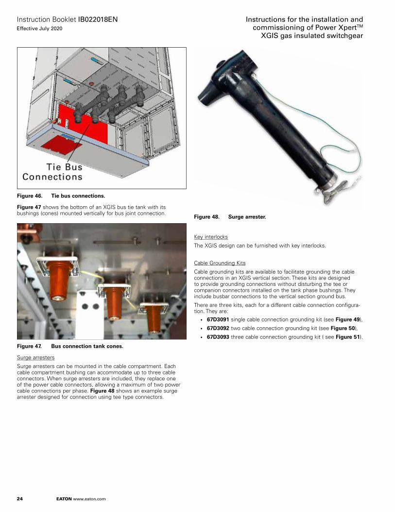
Figure 46. Tie bus connections.
Figure 47 shows the bottom of an XGIS bus tie tank with its bushings (cones) mounted vertically for bus joint connection.
Figure 47. Bus connection tank cones.
Surge arresters
Surge arresters can be mounted in the cable compartment. Each cable compartment bushing can accommodate up to three cable connectors. When surge arresters are included, they replace one of the power cable connectors, allowing a maximum of two power cable connections per phase. Figure 48 shows an example surge arrester designed for connection using tee type connectors.
Figure 48. Surge arrester.
Key interlocks
The XGIS design can be furnished with key interlocks.
Cable Grounding Kits
Cable grounding kits are available to facilitate grounding the cable connections in an XGIS vertical section. These kits are designed to provide grounding connections without disturbing the tee or companion connectors installed on the tank phase bushings. They include busbar connections to the vertical section ground bus.
There are three kits, each for a different cable connection configura-tion. They are:
• 67D3091 single cable connection grounding kit (see Figure 49),
• 67D3092 two cable connection grounding kit (see Figure 50),
• 67D3093 three cable connection grounding kit ( see Figure 51).

25
Instruction Booklet IB022018ENEffective July 2020
Instructions for the installation andcommissioning of Power XpertTM
XGIS gas insulated switchgear
EATON www.eaton.com
Figure 49.
POWER XPERT XGISCABLE GROUNDING KIT1250 A, ONE CABLE
NOTE: TEE CONNECTORS NOT INCLUDED
XGIS cable grounding kit, one cable.
Figure 50.
POWER XPERT XGISCABLE GROUNDING KIT1250 A, TWO CABLES
NOTE: TEE CONNECTORS NOT INCLUDED
XGIS cable grounding kit, two cables.
Figure 51.
POWER XPERT XGISCABLE GROUNDING KIT1250 A, THREE CABLES
NOTE: TEE CONNECTORS NOT INCLUDED
XGIS cable grounding kit, three cables.
1.3.6 XGIS vertical section configurations
XGIS vertical sections come in five basic configurations. Options are available to customize the equipment for each application. The configurations are • Feeder/incoming• Bus tie• Bus sectionalizer• Disconnector
• Cable connector

26
Instruction Booklet IB022018ENEffective July 2020
Instructions for the installation andcommissioning of Power XpertTM
XGIS gas insulated switchgear
EATON www.eaton.com
1.3.6.1 Feeder/incoming
The feeder/incoming vertical section includes both the 3PDS and the vacuum interrupter circuit breaker. It includes SSIS main bus and cable connections. This section can be furnished with fused VTs with a disconnect switch, cable CTs, remote-mounted fused VTs or surge arresters.
Figure 52. Feeder/incoming one-line.
1.3.6.2 Bus tie
The bus tie vertical section includes both the 3PDS and the vacuum circuit breaker. It is intended to connect two separate buses. It can be furnished with a set of VTs with the VT earthing switch and bus CTs.
Figure 53. Bus tie one-line.

27
Instruction Booklet IB022018ENEffective July 2020
Instructions for the installation andcommissioning of Power XpertTM
XGIS gas insulated switchgear
EATON www.eaton.com
1.3.6.3 Bus sectionalizer
The bus sectionalizer vertical section is intended to connect or isolate buses without circuit breaker protection. It includes the 3PDS, but no circuit breaker. It can be furnished with a set of VTs with the VT earthing switch and bus CTs.
Figure 54. Bus sectionalizer one-line.
1.3.6.4 Disconnector
The disconnector vertical section includes only the 3PDS. It is intended to connect or isolate direct connections to the XGIS main bus. This section can be furnished with fused VTs with a disconnect switch, cable CTs, remote-mounted fused VTs or surge arresters.
Figure 55. Disconnector one-line.

28
Instruction Booklet IB022018ENEffective July 2020
Instructions for the installation andcommissioning of Power XpertTM
XGIS gas insulated switchgear
EATON www.eaton.com
1.3.6.5 Cable connector
The vertical section includes only a hard bus connection throughout the tank. It is intended to connect incoming or outgoing cable connections directly to the XGIS main bus. This section can be furnished with cable CTs, remote-mounted fused VTs or surge arresters.
Figure 56. Cable connector one-line.
Table 2, Table 3 and Table 4 list the vertical section dimensions, electrical data and relevant standards for Power XPert XGIS switchgear.
Table 5 lists the Power XPert XGIS switchgear rated operating conditions.

29
Instruction Booklet IB022018ENEffective July 2020
Instructions for the installation andcommissioning of Power XpertTM
XGIS gas insulated switchgear
EATON www.eaton.com
1.4 Type XGIS gas insulated switchgear ratings (tables 2, and 3)
Table 2. Vertical section dimensionsVertical section dimensions
Maximum amperage 1250 A 2000 A / 2500 A
Width 600 mm (23.62 in) 800 mm (31.5 in)Depth 1800 mm (70.87 in) 1800 mm (70.87 in)Height 2700 mm (106.3 in) 2700 mm (106.3 in)
Table 3. Electrical dataElectrical Data
System Units Value (1250 A / 2000 A / 2500 A)
Rated voltage kV 38 (60 Hz), 36 (50 Hz)Lightning impulse withstand voltage kV 170Power frequency withstand voltage kV 80Rated frequency Hz 50/60Internal arc class AFLRLoss of service continuity category LSC2B
Accessibility of compartments
Circuit breaker compartment Interlock-controlledBusbar compartment Tool-based/non-accessibleCable compartment Tool-based or interlock-controlledExternal degree of protection IP4XPrimary live parts degree of protection IP65Installation IndoorTemperature classification °C -5 to +40Relative humidity (max) % 95
Phase busbars
Rated normal current A 1250, 2000, 2500Rated short-time withstand current, rms symmetrical kA - 3 s. 31.5Rated peak withstand current kA 82
Ground bus
Rated short-time withstand current, rms symmetrical kA - 3 s. 31.5Rated peak withstand current kA 82
Circuit breaker ratings
Rated normal current A 1250 / 2000 / 2500Rated short-circuit breaking current, rms symmetrical kA 31.5Rated short-circuit making current, peak kA 82Rated short-time withstand current, rms symmetrical kA - 3 s. 31.5Class E2, M2, C1 for 1250 A, C2 for 2000 A / 2500 ANumber of full short-circuit breaking operations 30Rated operating sequence O - 0.3S - CO - 15S - COClass M2Number of operations - No-load or full load > 10,000 / > 2,000
Three-position disconnect switch
Number of operations > 2000Heat Loss for representative sections
1250 A 683 W2000 A 905 W2500 A 1554 W

30
Instruction Booklet IB022018ENEffective July 2020
Instructions for the installation andcommissioning of Power XpertTM
XGIS gas insulated switchgear
EATON www.eaton.com
Table 4. Relevant standardsRelevant standards
IEC 62271-100 High-voltage switchgear and controlgear - Part 100: Alternating current circuit breakersIEC 62271-102 High-voltage switchgear and controlgear - Part 102: Hi-voltage alternating current three-position disconnect switches and earthing switchesIEC 62271-200 High-voltage switchgear and controlgears - Part 200: AC metal-enclosed switchgear and control gear for rated voltages above 1 kV and up to and
including 52 kVIEC 60529 Degrees of protection provided by enclosures (IP code)IEC 62271-1 High-voltage switchgear and controlgear - Part one: Common specifications
Table 5. Operating conditionsNormal operating conditions, according to IEC 62271 – 1 for indoor switchgear
Ambient air temperature ≤ 40° C≤ 35° C on average over 24 hours≥ -5° C
Altitude ≤ 1000 mContact Eaton for applications above 1000 m.
Atmosphere No dust, smoke or corrosive or inflammable gas or vapor, or salt (clean industrial air)Storage conditions To retain all of the functional qualities when stored for prolonged periods, we recommend that the equipment be stored in its original packaging,
in well-ventilated, clean, and dry conditions, sheltered from the sun and rain, at a temperature > -25° C and < +55° C.
Figure 57 shows outlines and dimensions for the 1250 A XGIS vertical section.
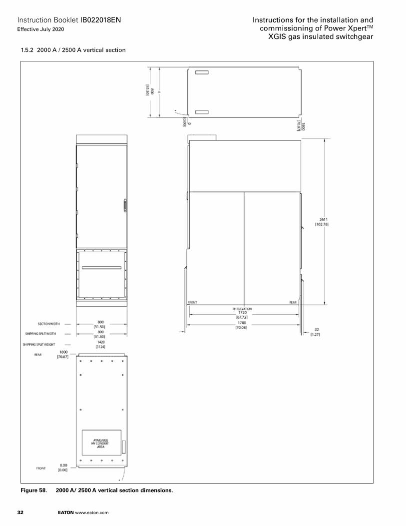
Figure 58 shows outlines and dimensions for the 2000 A and 2500 A XGIS vertical section.

31
Instruction Booklet IB022018ENEffective July 2020
Instructions for the installation andcommissioning of Power XpertTM
XGIS gas insulated switchgear
EATON www.eaton.com
1.5 XGIS vertical section outlines and dimensions
1.5.1 1250 A vertical section
Figure 57. 1250 A vertical section dimensions.
32
Instruction Booklet IB022018ENEffective July 2020
Instructions for the installation andcommissioning of Power XpertTM
XGIS gas insulated switchgear
EATON www.eaton.com
1.5.2 2000 A / 2500 A vertical section
Figure 58. 2000 A/ 2500 A vertical section dimensions.

33
Instruction Booklet IB022018ENEffective July 2020
Instructions for the installation andcommissioning of Power XpertTM
XGIS gas insulated switchgear
EATON www.eaton.com
1.6 SSIS conductor system
Solid Shielded Insulation System components provide modular shielded busbar conductors protected by solid insulation. The system includes shielded bus sections and coupling bus joints that provide mechanically robust installation that is impervious to environmental conditions, and free from local electric field around the conductors.
The SSIS conductors and connecting bus joints consist of three concentric layers:• The live conductor• The insulating layer over the conductor, and• The conductive shield outer layer
Figure 59 shows some example SSIS components and their arrangement as bus sections and terminations. Bus sections start at bus connection bushings (fitted in the tank) coupled to end or cross bus joints, extend using SSIS busbar, and terminate at bus connection bushings connected to end or cross type bus joints.
Figure 59.
End Bus Joint
Cross Bus Joint
Example SSIS components and assemblies.
1.6.1 SSIS bus in XGIS gas insulated switchgear
SSIS type busbars are installed as main bus conductors in XGIS switchgear.
Main busbars are installed and coupled to the bus connection bushings fitted on top of the sealed tank. Main horizontal busbars are enclosed in a separate compartment above the sealed tank.
Figure 60. Top view of XGIS tank showing tank bushings for busbar connections.
The bushings are mounted on top of the gas tank and are connected to the switching components in the tank via busbar inside the tank. See Figure 2.
SSIS cross bus joints are used to extend the bus between the adja-cent vertical sections. See Figure 34.
The SSIS busbar end bus joints, cross bus joints, caps, and busbar include a shield layer that is used to ground the exterior of the busbar system. The ground wires must be fastened to the ground studs on the tank. This will ensure the outer surface of the entire busbar system is at ground potential.
Figure 61. SSIS bus conductor shield grounds.
The bus joints used to connect bus sections differ with the bus rating. There are two bus joint types and two connection types. The Type C bus joint serves 1250 A bus, and provides connections in either cross or end configurations. The Type F bus joint serves 2500 A bus, and also provides connections in either cross or end configurations.

34
Instruction Booklet IB022018ENEffective July 2020
Instructions for the installation andcommissioning of Power XpertTM
XGIS gas insulated switchgear
EATON www.eaton.com
Bus joints are characterized by their bus size and by the bushing cones they can accommodate. • A Type C bus joint has a top throat suitable for a Type C plug and a
bottom throat suitable for a 1250 A bushing cone.• A Type F bus joint has a top throat suitable for a Type C plug and a
bottom throat suitable for a 2500 A bushing cone.• Each bus joint uses a threaded rod to connect the bus with the
tank cone. Type C and Type F bus joint rods are different.• End bus joints use a cylindrical insert to balance the clamshell
clamping force.
End bus joints use a cylindrical insert to balance the clamshell clamping force. See Figure 62, which shows the differences between Type C and Type F bus joints.
Figure 62.
1250A SSIS Bus Joints
2500A SSIS Bus Joints
Nut and Lock Washer
Type CEnd Bus Joint
Type CDouble Threaded Rod
Type CTank Bushing Cone
Type CPlug
1250 ABusbar
Type C Cross Bus Joint
Clamshell
Type FDouble Threaded Rod
Type FTank Bushing Cone
Type CPlug
Cap
Cap
Nut and Lock Washer
Type FEnd Bus Joint
2500 ABusbar
Type F Cross Bus Joint
Clamshell
Bus joint differences.
1.6.2 Power cable conductors in XGIS switchgear
The customer’s power cables terminate in XGIS by fitting separable cable connectors onto the XGIS tank bushings located in the power cable compartment. The installed cables are clamped in place using cable cleats mounted on the cable compartment cable brackets (see Figure 63).
The maximum number of cable connectors possible depends on the XGIS rating. Multiple connectors per phase are configured using tee or elbow type separable connectors (Figure 65). A surge arrester can be connected as the last connected device.
Figure 63.
Separable cable connectors
Cable cleats
1250A cable connectors in cable compartments.
The separable connector design will change depending upon the output cable dimensions. In every case, a maximum of three output connections per phase can be made: up to one tee connector and two coupling connectors, or one tee connector, one coupling connector and a surge arrester (see Figure 64).
The 2000 A and 2500 A XGIS designs use dual cable bushings per phase for cable connections (see Figure 65).

35
Instruction Booklet IB022018ENEffective July 2020
Instructions for the installation andcommissioning of Power XpertTM
XGIS gas insulated switchgear
EATON www.eaton.com
Figure 64.
CouplingConnector
Note:The Output Compartment can accommodate up to three connectors, or two connectors and a surge arrester.
XGIS Tank Wall
Cable Bushing
Output BushingBracket
CouplingConnectorCap
Space for
Cable CT
TeeConnector
Surge Arrester
Separable power cable connectors.
Figure 65. Cable separable connectors in 2000 A or 2500 A cable compartments.
The separable connectors include a shield layer that is used to ground the exterior of the connectors. The ground wires must be fastened to the compartment ground bus. This will ensure the outer surface of the separable connectors are at ground potential.
36
Instruction Booklet IB022018ENEffective July 2020
Instructions for the installation andcommissioning of Power XpertTM
XGIS gas insulated switchgear
EATON www.eaton.com
1.7 Voltage detection system
1.7.1 Connecting the voltage detection system cables to ground
m CAUTIONFAILURE TO EFFECTIVELY GROUND VOLTAGE DETECTING CABLES L1, L2, L3 PRIOR TO POWER FREQUENCY WITHSTAND VOLTAGE TESTING OR VLF VOLTAGE TESTING COULD RESULT IN PERSONAL INJURY OR EQUIPMENT DAMAGE.
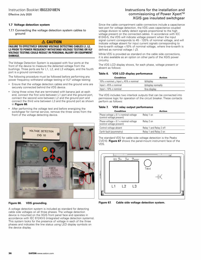
The Voltage Detection System is equipped with four ports at the front of the device to measure the detected voltage from the bushings. Three ports are for L1, L2, and L3 voltages, and the fourth port is a ground connection.
The following procedure must be followed before performing any power frequency withstand voltage testing or VLF voltage testing:• Ensure that the voltage detection cables and the ground wire are
securely connected behind the VDS device.• Using three wires that are terminated with banana jack at each
end, connect the first wire between L1 port and the ground port, connect the second wire between L2 and the ground port and connect the third wire between L3 and the ground port as shown in Figure 66.
• After performing the voltage test and before energizing the switchgear for normal service, remove the three wires from the front of the voltage detecting device.
Figure 66. VDS grounding.
A voltage detection system is included as standard for detecting cable side voltages on all three phases. The voltage detection device is mounted on the XGIS front panel face and operates in accordance with IEC 61243-5 (integrated voltage detection systems). This system looks for the presence of voltage in each of the three phases and indicates the line status using LED display symbols on the device display.
Since the cable compartment cable connectors include a capacitance test port for voltage detection, the VDS uses capacitance coupled voltage division to safely detect signals proportional to the high voltage present on the connected cables. In accordance with IEC 61243-5, the VDS will indicate voltage present when the input signal current corresponds to 45 - 120% of nominal voltage, and will indicate voltage absent for input current signals corresponding to line-to-earth voltage <10% of nominal voltage, where line-to-earth is defined as nominal voltage / √3.
While VDS is provided as standard on the cable side connections, it is also available as an option on other parts of the XGIS power circuitry.
The VDS LCD display shows, for each phase, voltage present or absent as follows:
Table 6. VDS LCD display performanceCondition Action
10% x nominal < Input < 45% x nominal displayInput > 45% x nominal display normallyInput < 10% x nominal no display
The VDS includes two interlock outputs that can be connected into permissive logic for operation of the circuit breaker. These contacts perform as follows:
Table 7. VDS relay output performanceCondition Action
Phase voltage > 0.1 x nominal voltage (control voltage present)
Relay 1 on
Phase voltage < 0.1 x nominal voltage (control voltage present)
Relay 2 on
Control voltage absent Relay 1 and Relay 2 offEarth fault (asymmetry) Relay 1 and Relay 2 on
The standard VDS for cable side voltage detection is the Peaks CVD10. Figure 67 shows the panel-mount instrument face of the VDS.
Figure 67. Cable side voltage detection system.

37
Instruction Booklet IB022018ENEffective July 2020
Instructions for the installation andcommissioning of Power XpertTM
XGIS gas insulated switchgear
EATON www.eaton.com
Section 2: Safe practices
2.1 Recommendations
Type XGIS vacuum circuit breaker elements are equipped with high speed operating mechanisms. They are designed with several built-in interlocks and safety features to provide safe and proper operating sequences.
m WARNINGTO PROTECT PERSONNEL ASSOCIATED WITH INSTALLATION, OPERATION, AND MAINTENANCE OF THESE SWITCHGEAR ELEMENTS, THE FOLLOWING PRACTICES MUST BE FOLLOWED:
• Only qualified persons, as defined in the local electrical code, who are familiar with the installation and maintenance of medium-voltage circuits and equipment, should be permitted to work on switchgear.
• Read these instructions carefully before attempting installation or commissioning of this equipment.
• Do not work on a closed breaker or a breaker with closing springs charged. The closing spring should be discharged and the main contacts opened before working on the breaker. Failure to do so could result in injuries.
• Do not use a circuit breaker by itself as the sole means of isolating a high voltage circuit. Open the 3PDS and follow good lockout and tagging rules, as well as all applicable codes, regulations and work rules.
• XGIS switchgear employs sulfur hexafluoride (SF6) in the enclosure tank, at slightly higher than nominal atmospheric pressure. Special precautions must be followed if service is required on the SF6 tank.
• SF6 is heavier than air and will displace air in a confined space. This can present a suffocation hazard.
• Never allow only one person access to the XGIS tank to perform maintenance or service work.
• Always replace the tank desiccant after performing tank maintenance.
• Once XGIS tank service is completed, personnel must clean their hands, faces and exposed skin immediately. Tools and PPE must also be cleaned.
• SF6 MUST NOT be discharged into the atmosphere. It should be collected and may be reused only after treatment and testing by qualified experts.

38
Instruction Booklet IB022018ENEffective July 2020
Instructions for the installation andcommissioning of Power XpertTM
XGIS gas insulated switchgear
EATON www.eaton.com
Section 3: Receiving, handling and storage
3.1 General
Type XGIS switchgear is subjected to complete factory production tests and inspection before being packed. XGIS vertical sections are shipped in packages designed to provide maximum protection to the equipment during shipment and storage and at the same time to provide convenient handling. Tools, such as the T-handle tool for manual 3PDS operation, and an Allen wrench for attaching voltage transformers, are shipped separately.
All SF6 tanks are shipped with the gas filled at rated pressure, with desiccant pouches inside the tank for interior moisture control. All vertical section-mounted power cable connectors are shipped with dust-proof caps installed.
3.2 Receiving
If an XGIS vertical section is not to be used immediately but is to be placed in storage, maximum protection can be obtained by keeping it packed as shipped.
Upon receipt of the equipment, inspect the vertical sections for any signs of damage or rough handling. The vertical sections should have been shipped in their upright position, as indicated on the shipping materials.
Open the vertical sections carefully to avoid any damage to the contents. Use a nail puller rather than a crow bar when required. When opening the containers, be careful to save any loose items or hardware that may be otherwise discarded with the packing material. Check the contents of each package against the packing list.
Examine the XGIS element for any signs of shipping damage such as broken, missing or loose hardware, damaged or deformed insulation and other components. File claims immediately with the carrier if damage or loss is detected and notify the nearest Eaton office.
3.3 Handling
The XGIS vertical section may be top heavy and subject to tipping danger.
Walking on or placing heavy objects on the vertical section top is prohibited.
Depending on the shipped vertical section weight, use one of the following to transport the vertical sections:• Fork lift• Crane
If using a fork lift, care must be taken to move the vertical section on its pallet, with the vertical section fully supported by the fork lift forks. Partial support of the vertical section may result in vertical section tilting with risk of falling over.
Avoid the use of abrupt movements of the vertical sections, to avoid equipment damage.
If using a crane, use a spreader bar rated for XGIS vertical section for lifting with the side mount lifting angles.
3.4 Unpacking
Contact Eaton for more information.
3.5 Lifting vertical sections
3.5.1 Lifting brackets attachment
A top lifting bracket (Figure 68 below) is available, and shall be attached to any XGIS vertical section (Figure 69 below) to enable the section to be lifted from the top.
The front of the bracket attaches to the rear of the LV compartment using (5) M10-1.25 x 25 lg SHCS, M10 wide washer (Figure 70). The rear of the bracket attaches to the rear panel of the upper assembly using (5) M10-1.25 x 25 lg SHCS, M10 wide washer (Figure 71).
Figure 68. Top lifting bracket.
Figure 69. Top lifting brackets for two attached sections.

39
Instruction Booklet IB022018ENEffective July 2020
Instructions for the installation andcommissioning of Power XpertTM
XGIS gas insulated switchgear
EATON www.eaton.com
Figure 70. Front mounting of top lifting bracket.
Figure 71. Rear mounting of top lifting bracket.
3.5.2 Lifting
When an XGIS vertical section is ready for installation, an overhead lifter or portable floor lifter can be used to move the vertical section in conjunction with the Eaton top lifting bracket.
When a vertical section is to be lifted, position the lifter over the vertical section and insert hooks into the vertical section top lifting bracket’s holes. Once the lifting hooks are securely seated in the lifting bracket holes, the vertical section can be carefully lifted and moved. Lifting chains should each be of equal length, at least 1 meter long each.
3.6 Storage
If the XGIS vertical section is to be placed in storage, maximum protection can be obtained by keeping it packed as shipped. Before placing it in storage, checks should be made to make sure that the vertical sections are free from shipping damage and is in satisfactory operating condition.
The storage area where XGIS vertical sections are stored must be clean, dry and well-ventilated, with an interior temperature of no less than 23o F. (-5o C.) Check the area periodically for condensation.
Store the vertical section packages upright, and do not stack them.
Indoor storage should be in a building with sufficient heat and air circulation to prevent condensation. If the building is not heated, the same general rule for heat as for outdoor storage, as noted below, should be applied.
Outdoor storage of the switchgear element is NOT recommended. If unavoidable, the outdoor location must be well drained and sheltered from sun, rain, snow, corrosive fumes, dirt, falling objects and excessive moisture. Containers should be arranged to permit free circulation of air on all sides and temporary heaters should be used to minimize condensation. Moisture can cause rusting of metal parts and deterioration of medium-voltage insulation. A heat level of approximately 400 watts for each 100 cubic feet of volume is recommended with the heaters distributed uniformly throughout the structure near the floor.
3.7 Tools and accessories
Manual operating T-handle for 3PDS Catalog Number (included with XGIS Switchgear) 87A1027H01
Note: main bus sections come in kits that include cleaning cloths with solvent, and silicone grease. If more is needed,
SSIS accessories: • cleaning cloths soaked in cleaning solvent (must be used; no
alternative is acceptable) 87A1045H01
• Main bus silicone grease 87A1046H01
• Tee connector silicone grease:
Top-mount voltage transformer installation/removal tool (refer to section 5.14.4 and Table 12) Catalog Number 87A1060G01.
The following tools and accessories are recommended for installation and commissioning (not provided with the XGIS switchgear):• SF6 leak detector - Eaton recommends Protec Equipment
Resources DILO 3-033-R200 • Gas Handling Equipment - Eaton recommends Relation
Corporation LM090
• Portable voltage transformer lifting system (refer to section 5.14, Voltage transformer installation and removal) Catalog Number 87A1090G01.
3.8 XGIS gas insulated switchgear vertical section weights
The weights in Table 8 below are for vertical sections including three-position disconnect switches and circuit breakers (as appropriate), incoming bus bar, bus fused VTs and cable CTs but excluding control and protection relays, and other custom features.
Table 8. Approximate vertical section weights (see exclusions above)
Vertical section A rating
Feeder / incoming Lb. (kg.)
Bus tie Lb. (kg.)
Bus sectionalizer Lb. (kg.)
DisconnectorLb. (kg.)
1250 3262 (1483) 3223 (1465) 3003 (1365) 3222 (1465)
2000 3669 (1668) 3633 (1651) 3411 (1550) 3629 (1650)
2500 3769 (1713) 3733 (1697) 3511 (1596) 3729 (1695)
1 gal. bucket 87A1098H01
5 gal. bucket 87A1098H02
40 lb. bucket 87A1098H03

40
Instruction Booklet IB022018ENEffective July 2020
Instructions for the installation andcommissioning of Power XpertTM
XGIS gas insulated switchgear
EATON www.eaton.com
Section 4: Initial inspection
m WARNINGBEFORE PLACING THE XGIS SWITCHGEAR IN SERVICE, CAREFULLY FOLLOW THE INSTALLATION PROCEDURE GIVEN BELOW. NOT FOLLOWING THE PROCEDURE CAN FAIL TO UNCOVER SHIPPING DAMAGE THAT MAY RESULT IN INCORRECT UNIT OPERATION LEADING TO DEATH, BODILY INJURY, AND EQUIPMENT DAMAGE.
Before attempting to put an XGIS switchgear into service, it should be carefully examined and operated manually and electrically. In addition, carefully examine the equipment for loose or obviously damaged parts. The following information is a guide for performing recommended checks and tests.
ote: N To ensure a satisfactory installation sequence and quality, the Power Xpert XGIS switchgear vertical sections’ installation should be performed under the supervision of trained and qualified field engineers.
The vertical section circuit breaker is shipped with its contacts open and closing springs in discharged state. The mechanical indicators on the front panel will indicate this.
Charge the closing springs by pumping the manual charging handle up and down approximately 25 times until a crisp metallic “click” is heard. This indicates that the closing springs are charged and is shown by the closing spring “charged” (yellow) indicator. Operate the push-to-close button.
The breaker will close as shown by the breaker contacts “closed” (red) indicator. Operate the push-to-open button. The breaker will open as shown by the breaker contacts “open” (green) indicator. After completing this initial check, leave the closing springs “discharged” and breaker contacts “open”.

41
Instruction Booklet IB022018ENEffective July 2020
Instructions for the installation andcommissioning of Power XpertTM
XGIS gas insulated switchgear
EATON www.eaton.com
Section 5: Installation
5.1 Qualified personnel
m WARNINGIMPROPERLY INSTALLING OR MAINTAINING THESE PRODUCTS CAN RESULT IN DEATH, SERIOUS PERSONAL INJURY, OR PROPERTY DAMAGE. READ AND UNDERSTAND THESE INSTRUCTIONS BEFORE ATTEMPTING ANY UNPACKING, ASSEMBLY, OPERATION OR MAINTENANCE OF THE CIRCUIT BREAKERS. INSTALLATION OR MAINTENANCE SHOULD BE ATTEMPTED ONLY BY QUALIFIED PERSONNEL. THIS INSTRUCTION BOOK SHOULD NOT BE CONSIDERED ALL INCLUSIVE REGARDING INSTALLATION OR MAINTENANCE PROCEDURES. IF FURTHER INFORMATION IS REQUIRED, YOU SHOULD CONTACT EATON.
5.2 General field installation requirements
XGIS vertical section installation should be completed after construction of the site electrical rooms are completely finished and power is available for lighting and field installation.
The destination electrical room should be kept dry and well ventilated. Cable vaults for power and control wiring must be completed, with structural support beams installed as in Figure 72.
Indoor operating conditions for the XGIS vertical sections must conform to an ambient temperature <40o C, altitude < 1000 m (consult Eaton representative for higher altitudes), with no dust, smoke or corrosive or inflammable gas or vapor, or salt (clean industrial air).
5.3 Installation requirements
The XGIS switchgear is designed for installation in the electrical room over cable vaults. It is very important that the installed lineup be level and mounted on the same plane. Eaton recommends that the electrical room design include steel rails embedded in the vault concrete, for mounting the XGIS switchgear.
The finished foundation surface shall be flat and level within 3 mm [0.12 in] in 800 mm [31.5 in] in any direction, left to right, front to back, and diagonally. Alternatively a local flatness value of 50 or value of 37 to 40 as defined in industry standard ASTM-E1155-96 and higher and an accompanying industry standard ACI 117-90 may be used to establish the flatness and levelness of the finished foundation.
It is recommended but not necessary to finish the foundation to the same requirements in front of the XGIS switchgear assembly in a traffic area defined by the end user. The minimum recommended foundation and anchoring system requirements are sufficient to withstand the combined tensile and overturning reactive forces imposed on the foundation at the XGIS switchgear assembly mounting points during a seismic event. Any deviation from these recommendations is the sole responsibility of end user.
Consult with a licensed structural or civil engineer if some other foundation methods are to be considered.
Power and signal cable separation in the cable vault must be sufficient to prevent induced eddy currents in power and signal cables.
Refer to the customer drawings for installation guidance.
When XGIS switchgear is specified to have arc-resistant rating, switchgear room must be equipped with an arc duct bulkhead, to provide expanding gases with an escape path in the event of an arcing fault.
For ingress of solid objects, XGIS vertical sections are designed to meet IP2X standards, with an option for IP4X upon request.
All low-voltage power cables and signal wiring passing through the switchgear must be gasketed and caulked to meet IP4X requirements.
5.4 Typical floor plan and minimum recommended clearances
XGIS switchgear is designed for input power cables entering from the top, output power cables entering from the bottom. Cables are supported by cable clamps provided in the cable compartment to prevent cable movement during an external fault. Depending upon the design, there may be external voltage transformers located in the cable vault but connected to separable cable connectors in the XGIS cable compartment.
Figure 72 shows an elevation view of typical vertical section cable vault requirements. Refer to the project design drawings for details.
Figure 73 shows an elevation view of typical vertical section front and rear access clearance requirements.
5.5 Vertical section ceiling height requirements
XGIS minimum ceiling requirements vary with the application. For vertical section lineups that do not include top-mounted fused voltage transformers, there is a minimum ceiling height requirement of 11.81 inches (300 mm).
For vertical section lineups that include top-mounted fused voltage transformers, the minimum ceiling height requirement is 47.24 inches (1200 mm). This clearance is required to facilitate replacement access to the vertical section voltage transformer compartment. See Figure 74.
Refer to the project design drawings for the details of the project clearance requirements.

42
Instruction Booklet IB022018ENEffective July 2020
Instructions for the installation andcommissioning of Power XpertTM
XGIS gas insulated switchgear
EATON www.eaton.com
Figure 72.
MV A
ND
LVC
AB
LE VAU
LT
31.5[800.00 m
m]
MIN
IMU
M(S
EE
NO
TE 1)
16.0[406.00 m
m]
MIN
IMU
M
BO
TTOM
VIEW 106.29
[2699.77 mm
]
70.87[1800.00 m
m]
RE
F
SE
E N
OTE
2
23.62 [600 mm
]1250A
31.50 [800mm
]2000A
15.75[400.00 m
m]
HV
EN
TRY
"SE
E FLO
OR
PLA
N D
ETA
IL FOR
DE
TAILE
D D
IME
NS
ION
S"
NO
TES
:
1.M
INIM
UM
RE
CO
MM
EN
DE
D C
AB
LE V
AU
LT DE
PTH
IS B
AS
ED
ON
US
E O
F MA
XIM
UM
(3) 1000 KC
M O
R 500 S
Q M
M M
VP
OW
ER
CA
BLE
S P
ER
PH
AS
E.
IT IS C
US
TOM
ER
'S R
ES
PO
NS
IBILITY
TO D
ETE
RM
INE
AP
PR
OP
RIA
TEC
AB
LE V
AU
LT DE
PTH
BA
SE
D O
N A
CTU
AL N
UM
BE
R O
F CA
BLE
S P
ER
PE
R P
HA
SE
, THE
IR S
IZES
, AN
D TO
TAL N
UM
BE
R O
F CA
BLE
S FO
R
THE
SW
TCH
GE
AR
LINE
UP
TO B
E IN
STA
LLED
IN TH
E V
AU
LT.
2.S
EE
FLOO
R P
LAN
DE
TAIL FO
R S
UG
GE
STE
D M
OU
NTIN
G O
PTIO
NS
3. OP
EN
ING
IS FO
R B
OTH
HV
AN
D LV
CA
BLE
EN
TRY
. SE
E FLO
OR
PLA
NFO
R A
DD
ITION
AL D
ETA
ILS.
4. MIN
IMU
M 1.00 IN
[25.4 MM
] FULL-D
EP
TH E
NG
AG
EM
EN
T RE
QU
IRE
DB
ETW
EE
N S
UP
PO
RT S
TRU
CTU
RE
AN
D S
WITC
HG
EA
R B
AS
E
CH
AN
NE
L ON
BO
TH E
ND
S O
F THE
LINE
UP
. SU
PP
OR
T EN
GA
GE
ME
NT
OF M
OR
E TH
AN
1.00 IN [25.4 M
M] C
OU
LD R
ES
ULT IN
INTE
RFE
RE
NC
EW
ITH A
VA
ILAB
LE LV
EN
TRY
AR
EA
.
5. FLOO
R S
UP
PO
RT S
TRU
CTU
RE
CO
NS
IDE
RA
TION
S TO
BE
D
ETE
RM
INE
D B
Y S
ITE E
NG
INE
ER
.
6. WH
EN
ZER
O S
EQ
UE
NC
E G
RO
UN
D FA
ULT C
T'S A
RE
UTILIZE
D, TH
EY
MU
ST B
E LO
CA
TED
IN TH
E C
AB
LE V
AU
LT. THE
RE
FOR
E, A
DD
ITION
AL
VA
ULT D
EP
TH W
ILL BE
RE
QU
IRE
D TO
AC
CO
MM
OD
ATE
THE
SE
D
EV
ICE
S. IT IS
THE
CU
STO
ME
R'S
RE
SP
ON
SIB
ILITY TO
DE
TER
MIN
E
AD
DITIO
NA
L VA
ULT D
EP
TH R
EQ
UIR
EM
EN
TS B
AS
ED
ON
DE
VIC
E
TYP
E A
ND
MO
UN
TING
PR
OV
ISIO
NS
.
7.87[200.00 m
m]
LV E
NTR
Y
6.0[150.00 m
m]
6.0[150.00 m
m]
MIN
IMU
M
SECTIO
N A
-A
1[25.4 m
m]
SE
E N
OTE
4
1[25.4 m
m]
SE
E N
OTE
4
SE
E N
OTE
5S
EE
NO
TE 5
A
SE
E N
OTE
5
A
SE
E N
OTE
3
SE
E N
OTE
3
67.72[1720 m
m]
1.57[40.00 m
m]
RE
F1.57
[40.00 mm
]R
EF
2.95[75.00 m
m]
2.95[75.00 m
m]
2.76[70.00 mm]
2.76[70.00 mm]
Example XGIS switchgear cable vault foundation diagram.

43
Instruction Booklet IB022018ENEffective July 2020
Instructions for the installation andcommissioning of Power XpertTM
XGIS gas insulated switchgear
EATON www.eaton.com
Figure 73. Typical vertical section clearance dimensions in control room.

44
Instruction Booklet IB022018ENEffective July 2020
Instructions for the installation andcommissioning of Power XpertTM
XGIS gas insulated switchgear
EATON www.eaton.com
Figure 74. XGIS vertical section minimum ceiling height requirements

45
Instruction Booklet IB022018ENEffective July 2020
Instructions for the installation andcommissioning of Power XpertTM
XGIS gas insulated switchgear
EATON www.eaton.com
5.6 Field installation precautions
5.6.1 Bolt tightening torques
Use standard bolts with a mechanical strength of 5.
Table 9. XGIS bolt tightening specificationsRecommended tightening torque in Nm(ft-lb)
Bolts Lubricant - None
M6 10.5 (7.7)M8 26 (19.2)M10 50 (36.9)
5.6.2 Handling of ssis silicone rubber insulator parts
SSIS (Solid Shielded Insulation System) components are insulated with silicone. All conductors, terminations and covering devices must be inspected for damage or defects prior to operation.
All SSIS silicone insulator surfaces must have no• Bubbles• Scratches• Visible damage• Foreign material contaminants• Evidence of wear
If any surface contamination is noticed on any SSIS component, it must be cleaned. Remove any dirt, oil or grease on any silicone insulator using a soft clean, lint-free wipe;
Clean silicone rubber insulators using a special wet cleaning wipe, furnished as part of the SSIS hardware kits. Apply medium force to clean the gray area of the silicone rubber insulator where it connects to the bus. Never wipe outside of the gray area.
Use a dry, soft, clean lint-free wipe to remove excessive cleaning solution. The solution may cause a slight expansion of the silicone rubber, so any cleaned silicone parts must be air-dried for at least 15 minutes.
Apply silicone grease evenly to the insulator and silicone rubber part, according to Table 10.
Table 10. Silicone grease application guidePart Silicone grease amount
SSIS bus and bus joints About 20gSSIS bus plug About 10gCable tee connector About 20gVoltage transformer, voltage sensor, lightning arrester, test tube and cable plug
About 10g
Clean and dry the contact surface of the socket and the silicone rubber part (the cable socket and bus insulator may also need cleaning). Apply another thin layer of silicone grease.
Assemble the cleaned conductors and couplings immediately.
5.7 Assembly
XGIS vertical sections are shipped individually, for assembly into lineups at the project site. Attaching the vertical sections together according to the following instructions provides mechanical strength and is required for the XGIS seismic rating.
See 5.7.2 for detailed assembly instructions.
5.7.1 Drawings
XGIS switchgear are furnished with project drawings specific to the project and client. Refer to the project drawings for details of the equipment and its installation.
5.7.2 Assembly instructions
Refer to Figure 75 for information on attaching AFLR sections, and Figure 76 for information on attaching AFL sections. Following the figures are checklists of attachment instructions including hardware requirements.

46
Instruction Booklet IB022018ENEffective July 2020
Instructions for the installation andcommissioning of Power XpertTM
XGIS gas insulated switchgear
EATON www.eaton.com
Figure 75.
2
7
94
1
11
10 3
6
5
8
SplicePlate
SplicePlate
SplicePlate
Splice Plate
Splice Plate
2 & 3 - Main Bus Compartment Vertical Joins
9 - Splice Plate
6 - Splice Plate
7 - Splice Plate
XGIS vertical section attachment guide for AFLR (Access Front Lateral Rear) sections.

47
Instruction Booklet IB022018ENEffective July 2020
Instructions for the installation andcommissioning of Power XpertTM
XGIS gas insulated switchgear
EATON www.eaton.com
Figure 76.
2
7
94
1
11
10 3
6
5
8
SplicePlate
SplicePlate
SplicePlate
Splice Plate
Splice Plate
Lorem ipsum
XGIS vertical section attachment guide for AFL (Access Front Lateral) sections.

48
Instruction Booklet IB022018ENEffective July 2020
Instructions for the installation andcommissioning of Power XpertTM
XGIS gas insulated switchgear
EATON www.eaton.com
The following installation and attachment instructions are set up in a checklist format to facilitate the process. Checkboxes are provided to aid in record keeping.
5.7.2.1 Locate the first vertical section on its foundation
ote: N Vertical sections intended as end vertical sections will be shipped with end caps mounted on their intended outside walls. Refer to the project draw-ings for lineup details.
Position the vertical section on the cable vault foundation according to the project lineup arrangement drawings. Refer to Figure 72 for details on vault rail flatness and level.
5.7.2.2 Bolt the vertical section to its rails
See Figure 72 and the project drawings for the details of attaching XGIS vertical sections to the system foundation rails. Use the hardware and torque specified.
5.7.2.3 Connect the vertical section to system ground
Note: in keeping with the facility’s ground system design, connect the first installed vertical section’s vertical section main grounding terminal to the facility ground system.
Although additional lineup vertical sections will be grounded to each other using interconnecting ground bus sections, it is recommended to connect the grounding terminals of the first and the last vertical sections’ vertical sections, as well as every two or three vertical sections in a lineup, to system ground.
5.7.2.4 Position the next vertical section
Position the next vertical section on the cable vault rails and next to the preceding section, according to the project lineup arrangement drawings.
5.7.2.5 Attach the vertical section to the previous vertical section
Use a torque wrench set for 50 Nm (36.9 ft-lb) to fasten all M10 hardware.
Section interior fastenings
Vertical section front edge bolts (see Figure 75 item 1 and Figure 77). Attach using 17 sets of M10-1.5 x 30 lg SHCS, M10 wide fat washer, M10 split lock washer, and M10 nut.
Figure 77. Front edge attachments.
Main bus compartment front bracket (see Figure 75, item 2)
Attach using 5 sets of M10-1.5 x 30 lg SHCS, M10 wide flat washer, M10 split lock washer, and M10 nut.
Main bus compartment rear bracket (see Figure 75, item 3)
Attach using 5 sets of M10-1.5 x 30 lg SHCS, M10 wide flat washer, M10 split lock washer, and M10 nut.
VT/upper relief compartment (see Figure 75, item 4)
Attach using 5 sets of M10-1.5 x 30 lg SHCS, M10 wide flat washer, M10 split lock washer, and M10 nut.
Vertical sections can be applied in either AFLR (Access Front Lateral Rear) or AFL (Access Front Lateral) configurations. The lower relief compartment attachment process is different for each configuration. In the AFL case, eight sets of attachment hardware are omitted.
Lower relief compartment for AFLR section (see Figure 75 item 5)
If the vertical section is a feeder section: Attach using 12 sets of M10-1.5 x 30 lg SHCS, M10 wide flat washer, M10 split lock washer, and M10 nut.
If the vertical section is a bus tie section:
Attach using 12 sets of M10-1.5 x 30 lg SHCS, M10 wide flat washer, M10 split lock washer, and M10 nut plus three along vertical plus one at mid-height, mid-depth,
Attach using four sets of M10-1.5 x 30 lg SHCS, M10 wide flat washer, M10 split lock washer, and M10 nut to attach the sections horizontally below the tank. See Figure 82 and Figure 83.
Lower relief compartment for AFL section (see Figure 76 item 5)
If the vertical section is a feeder section: Attach using four sets of M10-1.5 x 30 lg SHCS, M10 wide flat washer, M10 split lock washer, and M10 nut.
If the vertical section is a bus tie section:
Attach using four sets of M10-1.5 x 30 lg SHCS, M10 wide flat washer, M10 split lock washer, and M10 nut plus three along vertical plus one at mid-height, mid-depth,
Attach using four sets of M10-1.5 x 30 lg SHCS, M10 wide flat washer, M10 split lock washer, and M10 nut to attach the sections horizontally below the tank. See Figure 82 and Figure 83.

49
Instruction Booklet IB022018ENEffective July 2020
Instructions for the installation andcommissioning of Power XpertTM
XGIS gas insulated switchgear
EATON www.eaton.com
Main bus compartment vertical joins
Attach using 5 sets of M10-1.5 x 30 lg SHCS, M10 wide flat washer, M10 split lock washer, M10 nut.
Figure 78. Main bus compartment vertical joints.
Main bus compartment horizontal splice plate (see Figure 75, item 6).
Attach to studs on the top of the tank in each section using 10 sets of M8 wide washer, M8 split lock washer, M8 nut.
Figure 79. Main bus compartment splice plate.
Upper VT/relief compartment horizontal splice plate (see Figure 75, item 7)
Attach the front portion (ahead of the notch) holes to tank studs using 2 sets of M8 wide washer, M8 split lock washer, M8 nut.
Attach two holes (behind the notch) to one tank stud on each tank using 2 sets of M8 wide washer, M8 split lock washer, M8 nut.
Attach the remaining two sets of two holes using through hardware: Qty 4 sets of M8-1.25 lg SHCS, M8 wide washer, M8 split lock washer, M8 nut.
Figure 80. Upper VT/relief compartment splice plate.
Vertical section rear edge bolts (see Figure 75, item 8)
Attach using 17 sets of M10-1.5 x 30 lg SHCS, M10 wide flat washer, M10 split lock washer, and M10 nut.
Section exterior fastenings
Rear vertical splice plate (elbow) (see Figure 75, item 9)
Attach the horizontal part using 4 sets of M8-1.25 x 25 lg SHCS, M8 wide washer, M8 split lock washer, M8 nut.
Attach the vertical part using 12 sets of M8-1.25 x 25 lg SHCS, M8 wide washer, M8 split lock washer, M8 nut.
Figure 81. Rear vertical splice plate.

50
Instruction Booklet IB022018ENEffective July 2020
Instructions for the installation andcommissioning of Power XpertTM
XGIS gas insulated switchgear
EATON www.eaton.com
Front vertical splice plate (elbow) (see Figure 75, item 10).
The splice plate fits in a gap between the back of the low-volt-age compartment and the front of the main bus compartment.
Attach the horizontal part using 4 sets of M8-1.25 x 25 lg SHCS, M8 wide washer, M8 split lock washer, M8 nut.
Attach the vertical part using 12 sets of M8-1.25 x 25 lg SHCS, M8 wide washer, M8 split lock washer, M8 nut.
Top horizontal splice plate (see Figure 75, item 11).
Attach using 4 sets of M10-1.5 x 30 lg SHCS, M10 wide flat washer, M10 split lock washer, and M10 nut.
Bus tie vertical sections
If the system includes bus tie vertical sections, there will be a cutout in each vertical section’s cable compartment side walls to accommo-date bus connections.
These cutouts will require two attachments above the cutout and two attachments below. Each bus tie vertical section left-hand side wall will have holes for fasteners. The right-hand side wall will have weld nuts for mating with the attachment bolts.
Attach at the cutout top and bottom using 4 sets of M8-1.25 x 25lg SHCS, M8 wide flat washer, and M8 split lock washer.
Figure 82. Bus tie lower compartment attachments.
Figure 83. Bus tie lower compartment attachments.
Connect the cable compartment horizontal ground buses using a copper splice plate (see Figure 84 and Figure 85.
Figure 84. Ground bus copper splice plate.
Figure 85. Ground bus splice plate installed.
Install and connect SSIS bus in main bus compartments (see section 5.10).
Bolt next vertical section to cable vault rails.
5.7.2.6 Obtain the next vertical section in the lineup, and repeat from section 5.5.2.4
5.8 Low voltage control connections
Refer to the project schematic and wiring diagrams for information on control connections. Refer to Section 5.13 for information on cable routing, glands and caulking.
5.8.1 Auxiliary circuits available to the user
Refer to the project schematic and wiring diagrams for information on auxiliary signals available to the customer.
5.9 Installing SSIS bus and bus joints
Solid Shielded Insulation System components provide modular shielded busbar conductors protected by solid insulation. The system includes shielded bus sections and coupling bus joints so that the completed installation is mechanically robust, impervious to environmental conditions, and with the shielding features, has no local electric field around the conductors.

51
Instruction Booklet IB022018ENEffective July 2020
Instructions for the installation andcommissioning of Power XpertTM
XGIS gas insulated switchgear
EATON www.eaton.com
5.9.1 SSIS bus installation in XGIS gas insulated switchgear
SSIS type busbars are installed as main bus conductors on the XGIS system.
The SSIS conductors and couplers consist of three concentric layers:• The live conductor• The insulating layer• The conductive shield outer layer
Figure 86 shows some example SSIS components and their arrangement as bus sections and terminations. Bus sections start at bushings coupled to end or cross bus joints, extend using SSIS bus (solid sections), and terminate at bus connection bushings connected to end or cross bus joints.
Figure 2 shows the relative arrangement of the incoming bus connectors to the XGIS tank and its interior components.
See Figure 60 for an example of the XGIS main bus compartment and its bushing cones.
Note: All bushings without main busbar or cables installed shall have a grounded SSIS cap.
The bushings are mounted on top of the gas tank and are connected via bus to the switching components in the tank.
Figure 86. SSIS components and assemblies.
Nut and Lock Washer
Type CEnd Bus Joint
Type CDouble Threaded Rod
Type CTank Bushing Cone
1250 ABusbar
1250 A Busbar Conductor
Type C Cross Bus Joint
Clamshell Halves
Clamshell
1250 A SSIS Busbar and Bus Joints
Grounded Outer Sheath
Inner Insulation
End Bus Joint Disk
End Bus Joint Disk
SSIS cross bus joints are used to extend the bus between the adjacent vertical sections.
Figure 87. SSIS bus and bus joints installed on bus connection bushings above the sealed tank.
Figure 61 shows how the SSIS bus shield grounds are connected to XGIS bus connection bushings in the main bus compartment.

52
Instruction Booklet IB022018ENEffective July 2020
Instructions for the installation andcommissioning of Power XpertTM
XGIS gas insulated switchgear
EATON www.eaton.com
5.9.2 Field installation precautions
5.9.2.1 Handling of SSIS silicone rubber insulator plug-in parts
SSIS (Solid Shielded Insulation System) components are insulated with silicone. All conductors, terminations and covering devices must be inspected for damage or defects prior to operation.
All SSIS silicone insulator surfaces must have no• Bubbles• Scratches• Visible damage• Foreign material contaminants• Evidence of wear
If any surface contamination is noticed on any SSIS component, it must be cleaned. Remove any dirt, oil or grease on any silicone insulator using a soft clean, lint-free wipe;
Clean silicone rubber insulators using the provided special wet cleaning wipe. Apply medium force to clean the black area of the silicone rubber insulator connect to the bus. Never wipe from the black area to the red insulation surface;
Use a dry, soft, clean lint-free wipe to remove excessive cleaning solution. The solution may cause a slight expansion of the silicone rubber, so any cleaned silicone parts must be air-dried for at least 15 minutes.
Apply the provided silicone grease evenly to the insulator and silicone rubber part, according to Table 11.
Table 11. SSIS bus and joints silicone grease application guidePart Silicone grease amount
SSIS bus and bus joints About 20gSSIS bus plug About 10g
• Clean and dry the contact surface of the socket and the silicone rubber part. Apply another thin layer of silicone grease.
• Assemble the cleaned conductors and couplings immediately.
5.9.2.2 Preparations before installation
Unpack the equipment, check the contents of the accessory kit and the XGIS vertical sections. The accessory kit includes NB52 grease, silicone grease and cleaning wipes, etc.
5.10 Installing the bus and bushing
IMPORTANT
Successful application of the SSIS busbar connecting XGIS vertical sections depends upon proper centerline distances between vertical section phase cones. Busbar sections to be used between the cones will have these lengths. Confirm these distances before installing SSIS busbar sections. See Table 12.
Table 12. Main bus cone centerline distances
Adjacent section configurationCenterline distance between phase cones
Two 600 mm sections 600 mm
Two 800 mm sections 800 mm
One 600 mm and one 800 mm (left to right) phase A - 650 mmphase B - 700 mmphase C - 750 mm
One 800 mm and one 600 mm (left to right) phase A - 750 mmphase B - 700 mm;phase C - 650 mm
Use the smooth cleaning wipe supplied with the accessory kit to thoroughly clean the bus (copper bar) and silicone bus joint, on the inside and outside surfaces.
Figure 88. SSIS busbar and bush joint.
The silicone surface tends to absorb dirt which cannot be removed with the smooth wipe. If this has occurred, anhydrous alcohol or acetone cleaner can be used to wipe it clean.
After the silicone bushing has been cleaned, it must be air dried. Alcohol or acetone will cause the silicone to expand. Any expansion must be eliminated before final installation can be started. Use a drying gun to facilitate quick evaporation of alcohol from the surface after cleaning to minimize likelihood of dust re-settling on the silicone surface.
When a 2500 A main bus feeds vertical sections rated 1250 A, the bus joints used are used in a way that accommodates each connection point. See Figure 89.

53
Instruction Booklet IB022018ENEffective July 2020
Instructions for the installation andcommissioning of Power XpertTM
XGIS gas insulated switchgear
EATON www.eaton.com
Figure 89.
For Feeder vertical sections where the main (incoming) bus is rated 2500A and the vertical section is rated for a maximum of 1250A, a bus joint is used that has both Type C (rated 1250 A) and Type F (Rated 2500 A) receptacles.
Power comes into the bus joint through the bus connection and passes into the tank through a Type C cone. The unused bus joint receptacle is plugged and capped.
Cross Bus Joint
Type F Plug and Cap
Type F Receptacle
Clamshell
Bus Rated 2500 A
Bus Rated 2500 A
Clamshell
Type F Plug and Cap
Type F Receptacle
End Bus Joint
Type C Cone(1250 A)
Type C Cone(1250 A)
Tank
Tank
Bus Joint End Disk
Feeder section main bus connections.

54
Instruction Booklet IB022018ENEffective July 2020
Instructions for the installation andcommissioning of Power XpertTM
XGIS gas insulated switchgear
EATON www.eaton.com
Bus joints are shipped with the clamshell halves already installed in the joint housings. If the joint is an end joint, a copper disk is inserted at the end of the joint housing before the clamshell is installed.
Figure 90.
Clamshellhalves insertedin vertical barrel
Bus joint end view with clamshell halves
Apply supplied silicone grease (translucent white) evenly on the ash-colored cylindrical face of the insulated busbar.
Confirm that the clamshell halves are installed in the center of the bus joint, with the clamshell holes aligned vertically. Then insert one end of the SSIS busbar into the end or cross bus joint. Blowing compressed air between the joint with a nozzle can ease the assembly process. See Figure 91.
Figure 91.
EndBus Joint
SSIS Busbefore insertion
Applysilicone grease
evenly
CrossBus Joint
Inserting SSIS bus into bus joints.
Repeat this process for each joint. Then screw the attached ground wires to each joint, in a daisy chain fashion, with provided fasteners. Tighten them to finger tightness. The assembled joint should look like the image below for intermediate joints.
Figure 92. Completed bus installation in bus joints.
Lubricate the threads on the threaded rod. Insert the threaded rod into the bus joint top throat (type C or F cone) through the clamshell holes, and tighten by hand into the base cone. Then torque the rod to 45 Nm with a calibrated torque wrench.
Lubricate the outside of the tank bus cone (type C or F cone) with silicone. Lower the busbar and bus joints assembly onto the bus connection bushing (type C or F cone), such that threaded rod protrudes through the hole in the copper clamshell.
Figure 93.
Threaded rod
Clamshelltop disc withhole
Top view of end bus joint showing clamshell disc and threaded rod
Add the provided flat washer and lock washer over the rod to the top of the clamshell. Hand thread the provided nut onto the threaded rod. Torque the nut to 45 Nm (33.2 ft-lb) with a calibrated torque wrench.

55
Instruction Booklet IB022018ENEffective July 2020
Instructions for the installation andcommissioning of Power XpertTM
XGIS gas insulated switchgear
EATON www.eaton.com
Figure 94.
Threaded rod
Washerand Nut
Top view of end bus joint showing rod, washer and nut.
Figure 95.
SSIS Busbar
Clamshell
Tank BushingCone
ThreadedRod
Nut and Lock Washer
Copper Disk
Plug Receptacle
SSIS bus joint clamshell and threaded rod.
Lubricate the outside of the bus plug with silicone gel and insert the plug into the top of the bus joint. It helps to place a small wire between the two surfaces to allow air to escape as you push down on the plug. Push the plug down and turn it with a socket to tighten. Remove the wire if one was used to create an air gap. Torque to 45 Nm with a calibrated torque wrench. See Figure 96 .Add the black insulating cap to the top of the plug. Repeat this process for each joint.
Figure 96. End bus joint with plug inserted.
ote: N When the joints are loose, they are flexible. New sections of busbar assemblies can be added one at a time to existing sections of busbar.
Figure 97. Bus terminated at end vertical section tank bushings.
5.11 Low-voltage control cables
The low-voltage control wiring brought in from outside (through the Eaton blue top hat wire channels), or routed up through cutouts in the low-voltage compartment base, will require glands and caulking to completely fill any wireway apertures.
a) Reconnect the internal control wiring that was disconnected at the factory for shipping. The wiring as well as the connecting points are labeled.
b) Connect the wiring from external equipment to the terminal blocks located in the upper front compartment as shown on the switchgear electrical connection diagrams.
c) Do not modify the switchgear enclosure in any way in order to connect control wiring. When wiring connections that pass

56
Instruction Booklet IB022018ENEffective July 2020
Instructions for the installation andcommissioning of Power XpertTM
XGIS gas insulated switchgear
EATON www.eaton.com
between low voltage and medium voltage sections within a switchgear section, use the openings provided.
d) Once the wiring is completed, reseal the openings through which the wiring passes. There are two types of sealing systems: one is a non-adjustable opening (see Figure 98) and the other is an adjustable opening (see Figure 99 and Figure 100). Refer to the applicable section that follows to complete this process.
Figure 98. Caulk filling between low-voltage and medium-voltage sections.
Figure 99. Adjustable - medium-voltage side.
Figure 100. Adjustable - low-voltage side, fixed opening
e) If it is necessary to install additional wiring between any sections in the front of a switchgear vertical section, it is neces-sary to remove the factory installed caulk, install additional wiring, then reapply caulk as described in paragraph f) or para-graph g) below.
f) Fill all wiring openings through which wiring passes from the center mounted low voltage compartment to medium voltage compartments with caulk as shown in Figure 99. Bundle wires together on each side of the opening with a wire tie prior to applying caulk (silicone sealant certified to MIL -A-46106, Type I).
g) Fill all wiring openings through which wiring passes from the center mounted control compartment to the upper front compartment or to the lower front compartment (see Figure 100). Bundle wires together on each side of the opening with a wire tie prior to applying caulk (silicone sealant certified to MIL -A-46106, Type I).
Adjustable opening
h) If it is necessary to install additional wiring between any sections in the front of a switchgear vertical section, or to install wiring from external equipment, it is necessary to disassemble the wiring pass-through system, install additional wiring, then reassemble the wiring pass-through system as described in paragraph i) or paragraph k) below.
i) Wrap gasket material 1C19549H01 at least 1½ times around the wire bundle where it passes through the opening of the pass-through system.
j) Slide the movable plate of the pass-through system until the gasket is compressed and fills the opening completely. Tighten hardware to fasten the plate in place.
k) Place a 3/16” wide wire tie about 1/2” (12.7 mm) from the edge of the gasket material on each side of the opening.
Customer installed external control wiring entering the top or bottom of a switchgear vertical section
l) For top entry of external low voltage conductors, there are two removable cover plates (see Figure 101) on the top front of each vertical section .
Water-tight conduit hubs or water-tight gland fittings must be mounted in the cover plates to pass multi-conductor jacketed cables or multiple unjacketed wires ran in conduits into the switchgear .
If bundled unjacketed conductors are to be brought into the front section of the switchgear, they must be brought through a water-tight conduit hub in a workmanship manner (protection of insulation), then the conductors must be bundled together and conduit hub filled with caulk as described for the internal wiring in paragraphs f) and g) above .

57
Instruction Booklet IB022018ENEffective July 2020
Instructions for the installation andcommissioning of Power XpertTM
XGIS gas insulated switchgear
EATON www.eaton.com
Figure 101. External control wiring plate.
m) For bottom entry of external low voltage conductors, there are two removable cover plates on the floor of the front of a vertical section . For any foundation method it is the respon-sibility of the customer to provide a suitable means to seal to prevent escape of arc products or accommodate the escape of arc products through the cutouts made in the cover plates. Sub-paragraphs a and b following are suggestions for two commonly encountered foundations .
1. For switchgear installed on a concrete slab foundation, conduits are typically installed prior to the switchgear being set in place . For this situation, it is recommended the cover plates be cut to clear each conduit, reinstalled and sealed with caulk around the perimeter of the conduit, and around the wires or multiple conductor cables entering each conduit.
2. For switchgear installed on a steel floor, conduits may be installed prior to installation of the switchgear or after switchgear is installed. In this case, it is recommended the same procedure be followed as described in paragraph l) for conduits, jacketed multiple conductor cables, or bundled unjacketed conductors.
5.12 Installing cable adapters
Cables are connected to the tank bushings using medium-voltage separable connectors, connected to the cables.
The cables must be restrained to prevent movement in the event of short circuit conditions. Cable cleats and cable compartment cable bracing are used to fix the cables in place.
Eaton DTS1242 and DTB1242 cable adapters can be used on XGIS switchgear. Other cable adapters are also applicable, and can be applied once their suitability has been determined.
DTS1242 are used for one cable per phase. If more than one cable per phase is required, a combination of DTS1242 and DTB1242 cable adapters are used.
Surge arresters can also be applied to cable bushings. When surge arresters are required, the cable bushing will accommodate a maximum of two output cable adapters and the surge arrester.
Detailed installation instructions for Eaton cable connectors type DTS1242 and DTB1242 can be found in installation manuals MN650023EN and MN650024EN, respectively.
DTS1242: MN650023EN.pdf
DTB1242: 400 Series type C DTB1242 Mating Tee.pdf
5.12.1 Cable T connectors
Cable T connectors couple the tank output bushings to output cables. Their design permits further coupling of additional connectors (companion connectors) to the T connectors when parallel cables are needed.
Safety information
The instructions in this manual are not intended as a substitute for proper training or adequate experience in the safe operation of the equipment described. Only competent technicians who are familiar with this equipment should install, operate, and service it.
A competent technician has these qualifications:• Is thoroughly familiar with these instructions.• Is trained in industry-accepted high and low-voltage safe operating
practices and procedures.• Is trained and authorized to energize, de-energize, clear, and
ground power distribution equipment.• Is trained in the care and use of protective equipment such as arc
flash clothing, safety glasses, face shield, hard hat, rubber gloves, clampstick, hotstick, etc.
Safety instructions
Following are general caution and warning statements that apply to this equipment. Additional statements, related to specific tasks and procedures, are located throughout the manual.
Refer to Figure 64 for more information on cable T connectors, surge arresters and cable connection bushings.
m DANGERHAZARDOUS VOLTAGE. CONTACT WITH HAZARDOUS VOLTAGE WILL CAUSE DEATH OR SEVERE PERSONAL INJURY. FOLLOW ALL LOCALLY APPROVED SAFETY PROCEDURES WHEN WORKING AROUND HIGH- AND LOW-VOLTAGE LINES AND EQUIPMENT.
m WARNINGBEFORE INSTALLING, OPERATING, MAINTAINING, OR TESTING THIS EQUIPMENT, CAREFULLY READ AND UNDERSTAND THE CONTENTS OF THIS MANUAL. IMPROPER OPERATION, HANDLING OR MAINTENANCE CAN RESULT IN DEATH, SEVERE PERSONAL INJURY, AND EQUIPMENT DAMAGE.
m WARNINGTHIS EQUIPMENT IS NOT INTENDED TO PROTECT HUMAN LIFE. FOLLOW ALL LOCALLY APPROVED PROCEDURES AND SAFETY PRACTICES WHEN INSTALLING OR OPERATING THIS EQUIPMENT. FAILURE TO COMPLY CAN RESULT IN DEATH, SEVERE PERSONAL INJURY AND EQUIPMENT DAMAGE.

58
Instruction Booklet IB022018ENEffective July 2020
Instructions for the installation andcommissioning of Power XpertTM
XGIS gas insulated switchgear
EATON www.eaton.com
m WARNINGPOWER DISTRIBUTION AND TRANSMISSION EQUIPMENT MUST BE PROPERLY SELECTED FOR THE INTENDED APPLICATION. IT MUST BE INSTALLED AND SERVICED BY COMPETENT PERSONNEL WHO HAVE BEEN TRAINED AND UNDERSTAND PROPER SAFETY PROCEDURES. THESE INSTRUCTIONS ARE WRITTEN FOR SUCH PERSONNEL AND ARE NOT A SUBSTITUTE FOR ADEQUATE TRAINING AND EXPERIENCE IN SAFETY PROCEDURES. FAILURE TO PROPERLY SELECT, INSTALL OR MAINTAIN POWER DISTRIBUTION AND TRANSMISSION EQUIPMENT CAN RESULT IN DEATH, SEVERE PERSONAL INJURY, AND EQUIPMENT DAMAGE.
m DANGERALL ASSOCIATED APPARATUS MUST BE DE-ENERGIZED DURING ANY HANDS-ON INSTALLATION OR MAINTENANCE. FAILURE TO COMPLY WILL RESULT IN DEATH, SEVERE PERSONAL INJURY AND EQUIPMENT DAMAGE.
Cable cleats
All cables terminated at the XGIS cable bushing must be secured with cable cleats. Detailed installation instructions for cable cleats can be found in Eaton Cooper installation manual CTCC-10.
See Figure 24 for an example of cable cleats.
m CAUTIONIMPROPERLY SUPPORTED CABLE CONNECTORS COULD RESULT IN PERSONAL INJURY OR EQUIPMENT DAMAGE. THE APPARATUS BUSHING AND TEE CONNECTOR SHOULD NOT SUPPORT THE WEIGHT OF THE CABLE AND ARRESTER. CLAMP THE CABLE IMMEDIATELY BELOW THE CABLE JACKET SEAL, AND SUPPORT THE ARRESTER BELOW THE LOWER OF ARRESTER’S STEP. FAILURE TO FOLLOW THESE INSTRUCTIONS COULD LEAD TO SHORT CIRCUIT OR ARCING EVENT.
5.13 Installing current transformers
m DANGERALL ASSOCIATED APPARATUS MUST BE DE-ENERGIZED DURING ANY HANDS-ON INSTALLATION OR MAINTENANCE. FAILURE TO COMPLY WILL RESULT IN DEATH, SEVERE PERSONAL INJURY AND EQUIPMENT DAMAGE.
XGIS current transformers are installed in the factory prior to shipment but may be removed or changed in the field after the vertical sections have been aligned and attached.
The CTs are held in place by brackets attached to the vertical section surfaces. The hardware to be applied on the CTs will vary depending on the CT type, rating, applicable standards, quantity and location. The brackets to be applied and the mounting hardware to be used are specified on the project installation drawings.
5.13.1 Main bus compartment CTs
Main bus CTs are mounted on top of the tank, using brackets designed for the purpose. There are a variety of main bus CT bracket designs, depending on which CTs are to be installed.
In every case, the CTs will be installed on the tank top before the SSIS bus and bus joints are installed.
Figure 34 shows how the main bus CTs encircle the SSIS busbar. They are held in place by mounting brackets appropriate for the CT rating and applicable standard.
Main bus CTs are attached to the main bus compartment top surface using brackets and mounting hardware. Figure 35 shows the details of the CT mounting brackets for both XGIS design ranges.
CT examples
Figure 36 and Figure 37 are examples of main bus side CTs, for 1250 A and 2000 A / 2500 A, respectively.
Figure 38 shows the main bus CT brackets for 1250 A and 2500 A ratings.
5.13.2 Cable side CTs
Cable side CTs are also held in place using mounting brackets. There are two possible ways to connect the cable compartment output bushings: using cable connections or using bus connections.

59
Instruction Booklet IB022018ENEffective July 2020
Instructions for the installation andcommissioning of Power XpertTM
XGIS gas insulated switchgear
EATON www.eaton.com
5.13.2.1 Cable connections
Since the cable CTs are fitted over the cable bushing, the mounting process requires that the bracket be mounted over the cable bushing and the CTs fitted on to the cable bushing.
The cable bushing can accommodate a variety of CT designs, and multiple CTs per phase, space permitting.
Cable CT configuration will depend on the XGIS rating. 1250 A XGIS switchgear will use one cable bushing and one or more CTs per phase. 2000 A and 2500 A XGIS will use two cable bushings and one or more CTs per phase.
Note: All bushings without main busbar or cables installed shall have a grounded SSIS cap.
See Figure 39 for an illustration of a cable CT fitted over the cable bushing.
Figure 40 shows an example of a 1250 A cable side CT.
Figure 41 shows an example 2000 A / 2500 A cable side CT. One CT wraps around two bushings per phase.
Figure 42 shows an example of how the 1250 A CT bracket mounts over the cable connection bushings.
Figure 44 shows examples of 1250 A cable side CT brackets.
Note that the CTs can be arranged in a variety of configurations, with combinations of standard accuracy and high-accuracy models if desired. Threaded standoffs are used to fix the CTs in position in their brackets. In this example, the standoffs are emphasized in red.
Figure 43 and Figure 45 show examples of 2000 A / 2500 A cable side CTs and brackets.
5.13.2.3 Bus tie CTs
For XGIS switchgear designed for bus tie use, the tank design employs vertical cone bushings on the tank bottom instead of horizontal bushings for cable connections.
Where bus tie sections are connected together, SSIS bus will connect their output bushings, using bus joints. Tank bottom mounted CT brackets are used instead of cable connection bushings.
See Figure 46 for the Bus Sectionalizer configuration with tank bottom cones for bus joint connection.
See Figure 47 for an example of a bus tie tank with its connection cones projecting down from the tank bottom.
Figure 102 shows a bus sectionalizer tank bottom CT in its bracket.
Figure 102. Bus sectionalizer CT in bracket.
Figure 103 shows a bus tie CT in its bracket with the SSIS busbar passing through its aperture.
Figure 103. Illustration showing bus tie CT mounted in its bracket below the tank.

60
Instruction Booklet IB022018ENEffective July 2020
Instructions for the installation andcommissioning of Power XpertTM
XGIS gas insulated switchgear
EATON www.eaton.com
5.13.3 Installing CTs on main bus or cable side applications
m DANGERALL ASSOCIATED APPARATUS MUST BE DE-ENERGIZED DURING ANY HANDS-ON INSTALLATION OR MAINTENANCE. FAILURE TO COMPLY WILL RESULT IN DEATH, SEVERE PERSONAL INJURY AND EQUIPMENT DAMAGE.
The process for installing CTs will depend upon where they are to go.
5.13.3.1 Installing main bus or bus tie CTs
This procedure applies to each phase bus connection.
CTs installed in the main bus compartment or in the lower sectionalizing compartment for bus tie connections must first be threaded over their SSIS busbar as part of the SSIS bus system installation process. This is achieved by fitting the CT over the SSIS busbar prior to building the individual SSIS bus phase assemblies (typically on first XGIS section install), and attaching the CTs to CT mounting brackets already fastened to the tanks as detailed below.
1. Confirm that all power to the lineup is de-energized and locked out per the plant lockout/tagout procedures.
2. Mount the CT bracket to its attachment points on the tank.
3. Thread the SSIS busbar section through its CT(s).
4. Insert the SSIS busbar exposed bus into its bus joints (see section 5.9).
5. Place the combined SSIS busbar, CT(s) and bus joints on to the destination tank cones, and secure them.
6. Slide the busbar CT(s) into its (their) tank-mounted CT bracket.
7. Secure the CT(s) to its (their) bracket.
8. Connect the CT signal cable(s) to the CT secondary signal connectors.
As an alternative, the CTs and associated mounting brackets can be sub-assembled and attached to the tanks prior to inserting the SSIS busbars during installation (typically on additional XGIS sections installed adjacent to the first section).
5.13.3.2 Installing cable side cable connection CTs
1250 A CT mounting
1250 amp range CTs are mounted on single bushings per phase. The quantity of CTs applied will depend upon the customer requirements for signals and signal accuracy. Multiple CTs can be mounted on each phase bushing.
Refer to Figure 104 to see how the CT bracket attaches to the tank on two tank faces. Attachment hardware consists of a rear mounting bracket with horizontal CT braces, a front mounting bracket, mounting rods with spacers, and fasteners such as washers, lock washers and nuts (see Figure 105).
With the rear mounting bracket fastened to the studs on the vertical tank surface, fit each phase’s CTs over the bushing and horizontal mounting rods. Once the CTs are in place, put the spacers over the mounting rods (if required) and press them and the CTs against the rear mounting bracket.
Fasten the front 3-phase CT support angle with front CT brackets to the studs on the horizontal tank surface, sliding the front CT brackets over the threaded rods. Note that each phase front bracket should have a protective edge grommet installed around the inner diameter of the center hole. Use the M10 mounting hardware to secure. Ensure that all associated hardware is torqued to the appropriate specification for the respective thread size required to properly compress the locking washers.
Wire tie the CT signal wires to the underside of the CT support channels behind the front plates. Attach tie mounts to the tank studs and wire tie the wires to them. Route the wires into the vertical LV wire way through a grommet and up into the LV compartment.
Figure 104. 1250A Cable CT assembly
Figure 105.
Change spacer length to accommodatevarious CT con�gurations
1250 A cable CT bracket with rear bracket, braces, spacers and front bracket.
2000A / 2500 A CT mounting
2500 A range CTs are mounted on dual bushings per phase. The quantity of CTs applied will depend upon the customer requirements for signals and signal accuracy. Multiple CTs can be mounted on each phase’s bushings.
Refer to Figure 106 to see how the CT bracket attaches to the tank on two tank faces. Attachment hardware consists of a rear mounting bracket, a front mounting bracket, mounting rods with spacers, and fasteners such as washers, lock washers and nuts (see Figure 107).
With the rear mounting bracket, fit each phase’s CTs over the bushings and horizontal mounting rods. Once the CTs are in place, put the spacers (if required) over the mounting rods and press them and the CTs against the rear mounting bracket.

61
Instruction Booklet IB022018ENEffective July 2020
Instructions for the installation andcommissioning of Power XpertTM
XGIS gas insulated switchgear
EATON www.eaton.com
Fasten the front 3-phase CT support angle to the studs on the horizontal tank surface, then install the front CT bracket over the threaded rods. Note that each front bracket should have a protective edge grommet installed around the inner diameter of the center hole. Use the M10 mounting hardware to secure. Ensure that all associated hardware is torqued to the appropriate specification for the respective thread size required to properly compress the locking washers.
Bundle the CT signal wires as they are routed rearward away from each CT. Secure them to the upper or lower lateral flange of the rear mounting plate and route them to the right-hand cable compartment wall, downward toward the base, then forward along the tank wall into the vertical LV wire way, through a grommet and up into the LV compartment.
Figure 106. 2000 A / 2500 A cable CT assembly
Figure 107.
Change spacer length to accommodatevarious CT con�gurations
2000 A / 2500 A cable CT bracket with rear bracket, spacers, and front bracket.
5.13.4 Un-installing CTs on main bus or cable side applications
m DANGERALL ASSOCIATED APPARATUS MUST BE DE-ENERGIZED DURING ANY HANDS-ON INSTALLATION OR MAINTENANCE. FAILURE TO COMPLY WILL RESULT IN DEATH, SEVERE PERSONAL INJURY AND EQUIPMENT DAMAGE.
Un-installing CTs is the reverse of installing them.
m WARNINGTAKE CARE THAT ALL ELECTRICAL EQUIPMENT ASSOCIATED WITH THE SWITCHGEAR IS DE-ENERGIZED BEFORE WORKING ON THE EQUIPMENT. DISCONNECTING A CT SECONDARY SIGNAL CONNECTOR WHILE THE BUSBAR IS CONDUCTING CURRENT WILL RESULT IN A HIGH VOLTAGE ON THE SECONDARY WINDING, DAMAG-ING EQUIPMENT AND POSSIBLY INJURING PERSONNEL.
5.13.4.1 Un-installing main bus or bus tie CTs
This procedure applies to each phase bus connection.
1. Confirm that all power to the lineup is de-energized and locked out per the plant lockout/tagout procedures.
2. Disconnect the CT signal cable(s) to the CT secondary signal connectors.
3. Detach the CT(s) from its (their) bracket.
4. Move the CT(s) away from its (their) bracket by sliding it (them along the SSIS busbar.
5. Disconnect and dismount the busbar bus joints from their connection cones so that the bus joints, busbar and CTs can be removed from the main bus compartment.
6. Remove the busbar from one of its bus joints.
7. Slide the CT off of the busbar at the busbar decoupled end.
5.13.4.2 Un-installing cable side cable connection CTs
This procedure addresses one phase at a time.
Refer to Figure 42. It shows that the CT bracket attaches to the tank on two faces, the rear vertical face and the horizontal face. On the rear vertical face, horizontal studs extend to attach the bracket. On the horizontal face, the attachment studs are vertical.
1. Confirm that the switchgear is de-energized before performing any un-installing activities.
2. Disconnect and remove the cable tee connectors from the phase bushings.
3. Disconnect the CT secondary signal wiring from the CT connectors.
4. Brace the CT bracket so that it will not move while mounting hardware is loosened and removed.
5. Loosen and remove the fastening hardware (nuts and lock washers) from the front CT mounting bracket assembly.
6. Lower the front CT bracket assembly off of the vertical mounting posts.
7. Taking care not to scrape the connection bushings, slide each CT away from the tank rear face and off of the connection bushings.

62
Instruction Booklet IB022018ENEffective July 2020
Instructions for the installation andcommissioning of Power XpertTM
XGIS gas insulated switchgear
EATON www.eaton.com
5.14 Voltage transformer installation and removal
m WARNINGDO NOT ATTEMPT ANY WORK ON THIS EQUIPMENT SUCH AS INSTALLING COMPONENTS, PERFORMING ANY EXAMINATIONS, PERFORMING ANY ADJUSTMENTS, PERFORMING ANY SERVICING, OR PERFORMING ANY MAINTENANCE WHILE IT IS ENERGIZED. BEFORE PERFORMING ANY WORK, FOLLOW ALL APPROPRIATE HAZARD ASSESSMENT AND ENERGY CONTROL PRECAUTIONS AND PROCEDURES. VERIFY NO VOLTAGES ARE PRESENT ON ALL INCOMING AND OUTGOING CONDUCTORS, AND ANY ENERGY SOURCES CONTAINED WITHIN THE EQUIPMENT PRIOR TO SERVICING, THEN GROUND (CONNECT TO EARTH) ALL INCOMING AND OUTGOING CONDUCTORS ATTACHED TO THIS EQUIPMENT AND TO ANY INTERNAL ENERGY SOURCES.
Voltage transformers can be furnished on XGIS switchgear. If they are supplied, they are field mounted after the switchgear has been installed.
5.14.1 VT lifting truck
XGIS voltage transformers are heavy ( ~ 165 lb). An optional lifting truck (Catalog Number 87A1090G01) can be used to move and position the top mounted fused VTs for installation. This truck can be configured in two ways, convertible in the field from one to the other. The Lifting truck configurations are the High Lift Truck and the Low Lift Truck.
If a VT Lift Truck is employed, rail kits are available to provide the required truck rail parts and mounting hardware. The kits vary depending upon the task to be performed. They are:
• 87C2288 – Rail Kit for Front/Back Lifting
• 87C2289 – Rail Kit for Side Lifting (basic)
• 87C2290 – Side Lifting expansion Kit (additional rail sections and hardware for long lineups
See the project drawings for the details of converting the Lift Truck from High Lift to Low Lift configuration.
5.14.1.1 VT High Lift Truck
The default configuration, the “High Lift” truck, used on installations where the control room ceiling is high enough above the gear to accommodate the truck height above the vertical section top (see Figure 108 and Figure 109).
Figure 108. Top fused VT high lift truck.
The High Lift Truck can be configured to lift top VTs from in front of the vertical section to above the top of the section. The truck is then trolleyed back to the rear of the section over the VT compartment, and lowered into place in the VT compartment using the truck winch.
To do this, a temporary braced rail jig is installed at the target vertical section, which provides truck travel rails aligned with the VT compartment left and right wall top angles, for front to back movement. The VT Lift Truck is mounted on these rails.
The VT Lifting Truck hoist is used to raise a VT in its bracket from floor level to transfer height. The Truck and VT assembly is moved laterally to its target vertical section for installation. Then the VT assembly is lowered into place at its connection point. See Figure 109.
Figure 109. Top fused VT high lift truck on rails.

63
Instruction Booklet IB022018ENEffective July 2020
Instructions for the installation andcommissioning of Power XpertTM
XGIS gas insulated switchgear
EATON www.eaton.com
The rails are erected on the spot, with end stops at both ends of travel. Rail overall assembled length will depend upon travel orientation - either front to back or side to side. The truck’s grooved wheels sit on the rails and help to keep the truck on the rails during movement.
5.14.1.2 VT Low Lift Truck
The alternate configuration, the “Low Lift” truck, is used on installations where the room ceiling is too low for the High Lift Truck. In that case, the High Lift Truck is modified into the Low Lift configuration. See Figure 110.
VT Truck rails are installed at the rear of the gear lineup, for side to side travel. Rail sections can be added to extend the truck travel to any needed length for target vertical section access. See Figure 111.
The rails are aligned with the front and rear walls of the VT compartment. The Low Lift Truck is mounted on the rails, and a VT is winched from floor level to just above the VT compartment floor height. The truck is then trolleyed along the rails to the target vertical section VT compartment, and the VT is lowered into place using the truck winch.
Installing the fused main bus VTs requires a special tool (see 5.13.4 for details.)
Figure 110. Top fused VT low lift truck.
m WARNINGPROPER OPERATION OF THE LIFTING TRUCK REQUIRES ATTENTION TO PROPER ALIGNMENT OF THE TRUCK WHEELS ON THE MOUNTED RAILS. CARE MUST BE TAKEN TO MOVE THE TRUCK SLOWLY ON ITS RAILS, TO AVOID LOAD SWINGS DURING LIFTING, TRANSPORT OR LOWERING, AND TO PROPERLY STOP THE TRUCK AT THE RAIL END STOPS.
Figure 111.
End of lineup
Extendable rails
End stops
End stops
Top fused VT low lift truck on rails.
Figure 112.
VT Lift Position
VT front lift initial position.

64
Instruction Booklet IB022018ENEffective July 2020
Instructions for the installation andcommissioning of Power XpertTM
XGIS gas insulated switchgear
EATON www.eaton.com
Figure 113.
VT Lower Position
VT front lift final position.
m DANGERENERGIZED PARTS WILL CAUSE SERIOUS INJURY OR DEATH. DO NOT CONNECT A PLUG-IN TYPE VOLTAGE TRANSFORMER WHILE THE XGIS SWITCHGEAR IS ENERGIZED. BEFORE INSTALLING OR REMOVING THE VOLTAGE TRANSFORMER, CUT POWER TO THE RELEVANT BUSES AND GROUND THEM ACCORDING TO REGULATIONS.
5.14.2 Voltage transformer installation
Top voltage transformer compartment mounted VTs (fused and unfused)
Installing a top-mounted fused VT and its mounting bracket is facilitated by the VT Installation/Removal tool, Eaton catalog number 87A1060G01. Eaton will furnish one tool per XGIS lineup. This tool is composed of three elements, and additional tools can be purchased from Eaton or purchased from McMaster-Carr using the following catalog numbers:
ote: N some applications will require that the VT mounting brackets be fitted with fuse blocking plates to prevent access to the VT fuses without removing the VT.
Figure 114.
Metal-CladPlug-in VT(One per phase)
VT Lifting /MountingBracket
Fused VTMountingBracketBrace
Fuse Blocking Plate Welded to Mounting Bracket(One per phase)
VT lifting / mounting brackets with fuse blocking plates installed.
Table 13. Top VT installation tool componentsCatalogNumber Description
5522A39 3/8” square drive socket extension, 34 inches
7229A62 Magnet bit holder, 3/8” square drive, 1/4’ bit hex shank
4309A16 Screw-holding 6 mm hex bit, 1/4”hex shank
One VT installation/removal tool set will be provided per lineup.
The voltage transformer is provided with a mounting bracket installed. The mounting bracket also serves as an installation bracket. Do not remove this bracket. Figure 32 shows a fused bus VT with its mounting bracket.
Voltage transformers are heavy - they can weigh as much as 165 lb. If it is necessary to install or remove a voltage transformer, care must be taken to properly handle the voltage transformer in a safe and secure manner.
Prepare the vertical section for VT installation
• Remove the top sheet from the VT compartment. Loosen the VT mounting bracket back brace to facilitate VT installation. Figure 115 shows the VT bracket brace.
Voltage transformer lift truck
The VT lift truck comes in two designs to accommodate site ceiling heights.
The high height design works best on sites where the control room ceiling is high (see Figure 74), while the low height design works best for low ceilings.
With the high lift truck, a VT can be installed from the front of a vertical section. The low height design requires that the vertical section side sheet be removed, and the VT installed from the side for lateral access to the VT compartments.

65
Instruction Booklet IB022018ENEffective July 2020
Instructions for the installation andcommissioning of Power XpertTM
XGIS gas insulated switchgear
EATON www.eaton.com
To see the two versions of a voltage transformer lift truck available, see Figure 108 and Figure 110.
To install a top voltage transformer,
• Choose a lift truck configuration that applies to the ceiling height. • Temporarily install lift truck rails at the top of the target vertical
section. The rail assembly has end stops to prevent the lift truck from rolling back off of the rails.
• Mount the lift truck (low lift or high lift) on to the rails.• Low lift truck: use the lift truck winch to raise a VT in its bracket to
the VT compartment floor height.• High lift truck: use the lift truck winch to raise a VT in its bracket
above the vertical section top.• Move the lift truck and VT over the rails until they are above the
destination VT compartment.• Lower the VT into the VT compartment.
Figure 115. Fused bus VT mounting bracket brace.
• Remove the VT port cover plate from the top of the XGIS tank. Figure 116 shows the VT connection ports.
Figure 116. VT connection ports.
• Remove the VT compartment front wall access bracket to facilitate lowering the VT and bracket into place. Figure 117 shows the VT install access bracket being removed.
Figure 117. Remove VT install access bracket,
• Apply silicone grease to the VT port inner cone on the top of the XGIS tank.
Lower VT into installation position using the VT lift truck
• Lift the VT using the lifting bracket eye and a lifting device rated for over 1000 lbs (see Figure 118).
Figure 118. Lower VT bracket into place in VT compartment.
• Lower the VT into place (see Figure 119).
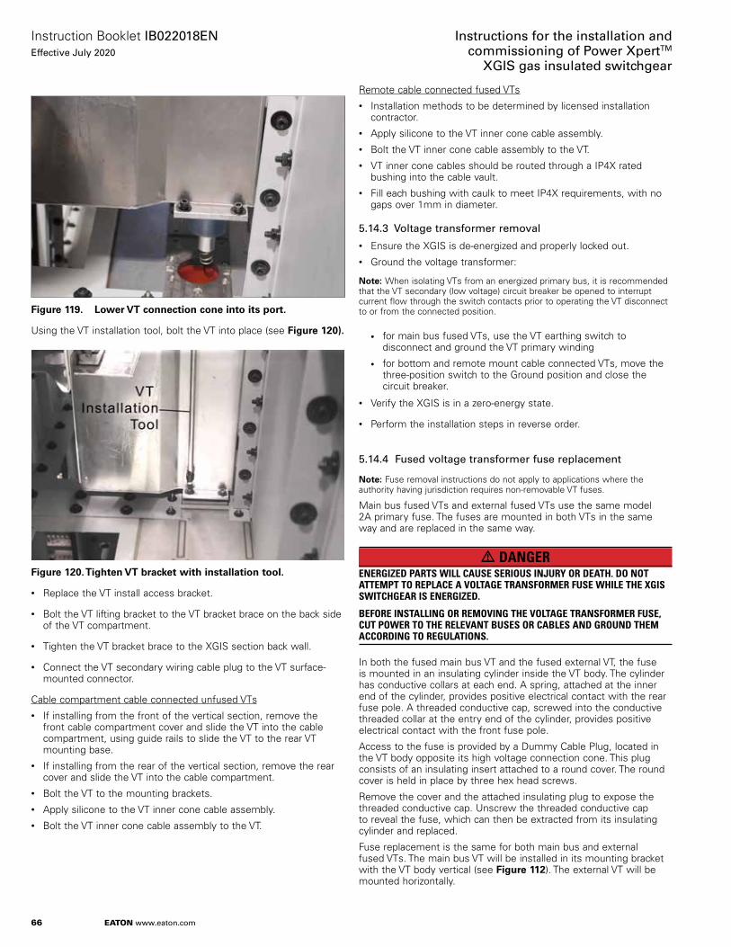
66
Instruction Booklet IB022018ENEffective July 2020
Instructions for the installation andcommissioning of Power XpertTM
XGIS gas insulated switchgear
EATON www.eaton.com
Figure 119. Lower VT connection cone into its port.
Using the VT installation tool, bolt the VT into place (see Figure 120).
Figure 120. Tighten VT bracket with installation tool.
• Replace the VT install access bracket.
• Bolt the VT lifting bracket to the VT bracket brace on the back side of the VT compartment.
• Tighten the VT bracket brace to the XGIS section back wall.
• Connect the VT secondary wiring cable plug to the VT surface-mounted connector.
Cable compartment cable connected unfused VTs• If installing from the front of the vertical section, remove the
front cable compartment cover and slide the VT into the cable compartment, using guide rails to slide the VT to the rear VT mounting base.
• If installing from the rear of the vertical section, remove the rear cover and slide the VT into the cable compartment.
• Bolt the VT to the mounting brackets.• Apply silicone to the VT inner cone cable assembly. • Bolt the VT inner cone cable assembly to the VT.
Remote cable connected fused VTs• Installation methods to be determined by licensed installation
contractor. • Apply silicone to the VT inner cone cable assembly. • Bolt the VT inner cone cable assembly to the VT.• VT inner cone cables should be routed through a IP4X rated
bushing into the cable vault. • Fill each bushing with caulk to meet IP4X requirements, with no
gaps over 1mm in diameter.
5.14.3 Voltage transformer removal
• Ensure the XGIS is de-energized and properly locked out.• Ground the voltage transformer:
ote: N When isolating VTs from an energized primary bus, it is recommended that the VT secondary (low voltage) circuit breaker be opened to interrupt current flow through the switch contacts prior to operating the VT disconnect to or from the connected position.
• for main bus fused VTs, use the VT earthing switch to disconnect and ground the VT primary winding
• for bottom and remote mount cable connected VTs, move the three-position switch to the Ground position and close the circuit breaker.
• Verify the XGIS is in a zero-energy state.
• Perform the installation steps in reverse order.
5.14.4 Fused voltage transformer fuse replacement
ote: N Fuse removal instructions do not apply to applications where the authority having jurisdiction requires non-removable VT fuses.
Main bus fused VTs and external fused VTs use the same model 2A primary fuse. The fuses are mounted in both VTs in the same way and are replaced in the same way.
m DANGERENERGIZED PARTS WILL CAUSE SERIOUS INJURY OR DEATH. DO NOT ATTEMPT TO REPLACE A VOLTAGE TRANSFORMER FUSE WHILE THE XGIS SWITCHGEAR IS ENERGIZED. BEFORE INSTALLING OR REMOVING THE VOLTAGE TRANSFORMER FUSE, CUT POWER TO THE RELEVANT BUSES OR CABLES AND GROUND THEM ACCORDING TO REGULATIONS.
In both the fused main bus VT and the fused external VT, the fuse is mounted in an insulating cylinder inside the VT body. The cylinder has conductive collars at each end. A spring, attached at the inner end of the cylinder, provides positive electrical contact with the rear fuse pole. A threaded conductive cap, screwed into the conductive threaded collar at the entry end of the cylinder, provides positive electrical contact with the front fuse pole.
Access to the fuse is provided by a Dummy Cable Plug, located in the VT body opposite its high voltage connection cone. This plug consists of an insulating insert attached to a round cover. The round cover is held in place by three hex head screws.
Remove the cover and the attached insulating plug to expose the threaded conductive cap. Unscrew the threaded conductive cap to reveal the fuse, which can then be extracted from its insulating cylinder and replaced.
Fuse replacement is the same for both main bus and external fused VTs. The main bus VT will be installed in its mounting bracket with the VT body vertical (see Figure 112). The external VT will be mounted horizontally.

67
Instruction Booklet IB022018ENEffective July 2020
Instructions for the installation andcommissioning of Power XpertTM
XGIS gas insulated switchgear
EATON www.eaton.com
The fuse replacement procedure is as follows.
Figure 121.
Fuse
Fuse
Fused External VT(mounted horizontally)
Dummy Cable Plug
Fused Main Bus VT(mounted vertically inVT mounting bracket,not shown here)
Fused VT fuse access dummy cable plugs
Fused VT fuse removal procedure• Confirm that power is removed from the VT primary winding
and that the VT primary winding is connected to ground before continuing this procedure. Observe all lockout/tagout procedures.
Figure 122. Fused VTs at start of procedure.
• Using an appropriate hex head screwdriver, release and remove the Dummy Cable Plug by loosening the three attachment screws and pulling the Dummy Cable Plug out of the fuse access port.
Figure 123. Remove Dummy Cable Plug.
• Using a large flat head screwdriver, loosen and remove the threaded conductive cap holding the fuse in place in its insulating body.
Figure 124. Remove threaded cap.
• Using a suction cup or other attachment device, draw the fuse out of its insulating cylinder container.

68
Instruction Booklet IB022018ENEffective July 2020
Instructions for the installation andcommissioning of Power XpertTM
XGIS gas insulated switchgear
EATON www.eaton.com
Figure 125. Extract fuse.
• Insert the replacement fuse.• Insert and tighten the threaded conductive cap.• Insert the Dummy Cable Plug into the orifice, pushing the
insulating plug far enough to make the cap flush with the VT body.• Tighten the three hex head screws to fasten the cap to the VT
body.• Confirm that all tools and loose parts are removed from the work
area. Disconnect the VT primary from ground. Following all safety procedures, reconnect the VT primary to its power circuit and restore power to the high voltage circuit.
5.15 Auxiliary cabinet installation
If it is necessary to add an auxiliary cabinet to an XGIS lineup, it can be added to either end of the lineup.
Refer to 1.3.5 Optional features. A 600 mm wide or 800 mm wide auxiliary cabinet can be added to a lineup end by attaching it to an existing XGIS vertical section’s end sheet (see Figure 126), and adding a bracing angle to the rear of the auxiliary cabinet. See Figure 128.
Figure 126.
Vertical Section
Vertical SectionEnd Sheets
AuxiliaryPanel
Bottom Low Voltage Wireway Cover Plate
Top Low Voltage Wireway Cover Plate
Auxiliary cabinet addition front view.
The auxiliary cabinet comes with an overhanging low voltage wireway, so that the wireway extends over the lineup end section end sheet. It is bolted into place using bolts, lock washers and nuts, attaching the auxiliary cabinet to the end vertical section end sheet.
A rear attachment angle is added at the back of the auxiliary cabinet, where the cabinet meets the vertical section end sheet, and is bolted into place on both surfaces using bolts, lock washers and nuts. See Figure 128.
Auxiliary section lifting means
If it is necessary to place an auxiliary cabinet by lifting it into position before attachment, the cabinet has four 1/2 inch (M12) eye bolts placed in the corners of the auxiliary panel top surface (see Figure 127).
To prepare the auxiliary panel for lifting, remove its top low voltage wireway top plate to access the lifting eyes holes (Figure 127).

69
Instruction Booklet IB022018ENEffective July 2020
Instructions for the installation andcommissioning of Power XpertTM
XGIS gas insulated switchgear
EATON www.eaton.com
Figure 127.
Auxiliary CabinetTop Low VoltageWireway Top Plate
Auxiliary CabinetLifting Eye Bolts (M12)
Auxiliary cabinet lifting eye holes.
Figure 128.
Vertical SectionRear side
Vertical SectionEnd Sheets
Rear AttachmentAngle
Auxiliary Panel
Auxiliary cabinet addition rear view
Attaching an auxiliary panel to either end of a lineup
Every lineup end vertical section has end sheets bolted to its frame. These end sheets have bolt holes that are used to attach the end sheet to the vertical section. The bolt holes that usually attach an end sheet to the vertical section can also be used to attach an auxiliary cabinet.
Use ten (10) M8x75mm allen head bolts and M8 washers to attach the auxiliary panel to the vertical section end sheet. See Figure 129 and Figure 130.
Figure 129.
Front ofVertical Section
End sheet holes for 10 - M8x75 boltswith M8 washer
End section with 10 bolt holes available for auxiliary section.

70
Instruction Booklet IB022018ENEffective July 2020
Instructions for the installation andcommissioning of Power XpertTM
XGIS gas insulated switchgear
EATON www.eaton.com
Figure 130.
Aux. section holes for 10 - M8x75 boltswith M8 washer
Front ofVertical Section
Auxiliary section placed next to vertical section for attachment.
Attach the L bracket to the adjacent vertical the section and the auxiliary section rear panel. The L bracket has ten bolt holes on one surface and four bolt holes on it other surface.
Use seven (7) M8x30 bolts to attach the L bracket to the auxil-iary panel rear wall.
Use four (4) M8x75 bolts to attach the L bracket to the vertical section end sheet. See Figure 131.
Rear ofVertical Section
Vertical SectionEnd Sheets
Rear AttachmentAngle
Auxiliary Panel
7 - M8x30bolts
4 - M8x75bolts
Figure 131. Attach L bracket to vertical section side panel and auxiliary section rear panel.

71
Instruction Booklet IB022018ENEffective July 2020
Instructions for the installation andcommissioning of Power XpertTM
XGIS gas insulated switchgear
EATON www.eaton.com
Section 6: CommissioningThis section is intended to be an informal reference only and covers recommended XGIS switchgear commissioning practices. It is ultimately the responsibility of the commissioning contractor to determine the level of activities required to satisfy the project requirements on an application by application basis.
Commissioning the XGIS system will include visual inspections, wire checks, power-off sequencing checks using external control power, electrical and manual operation checks for the 3PDS and circuit breaker, and local and external control checks as per the project diagrams.
Tests will include (see section 7):• Insulation resistance (at 10KV)• Field power frequency withstand test (at 60 kV) • Contact resistance (at 100 amps)• SF6 gas leak check (sniffer or pressure check)• SF6 sample (moisture and purity)• Ground continuity check to ensure switch is properly grounded
(use 100 amp ductor)• Test voltage transformers (megger and ratio)• Test current transformers (ratio and polarity)
6.1 Pre-commissioning final inspection
Final Inspection prior to commissioning• Check that gas pressure in the sealed tanks is within the specified
range.• Clean the cabinet surface and the control chamber; check coating
of the cabinet for damage; if there is any, use the right paint to touch up.
• Replace parts removed during installation.• Take out all tools and other devices that do not belong to the
switchgear.• Verify that the switchgear is in normal state.• Verify that surrounding environment is in normal state.
6.2 Commissioning procedures
6.2.1 Preparations for commissioning
Prepare for commissioning by performing the following tasks before connecting high-voltage power:• Connect auxiliary and control power and check the polarities as
appropriate.• Check the effectiveness of 3PDS and circuit breaker (if furnished)
mechanical and electrical interlocks according to the information in Section 4.2.1 (for the 3PDS) and 4.2.2 (for the CB) of the Operation and Maintenance Manual, IB022017EN.
• Perform function tests for connected protective devices according to relevant standards.
• Check the overall condition of the system.• Locate the SF6 gas handling instructions in a prominent place in
the Switchgear Room.• Locate emergency procedures for SF6 gas leaks in a prominent
place in the Switchgear Room.• Train the site operations personnel in the operation of the XGIS
equipment.• Confirm that upstream and downstream electrical equipment has
been prepared for the commissioning of the XGIS switchgear.
• Check the switchgear power and control connections, power supplies, external control, grounding and environment:• Power bus
• Control wiring
• Auxiliary power and its polarity (as appropriate)
• Remote control system connections and operation
• External grounding of the switchgear grounding terminals
• Equipment in switchgear
See Appendix A for a recommended XGIS Switchgear Commissioning Checklist.
6.2.2 Startup
• Comply with all relevant safety regulations.• Confirm that the vertical section circuit breaker is in its open
position.• Confirm that the vertical section 3PDS is in its closed position.• Clear the switchgear area of miscellaneous debris, work tools and
extraneous equipment.• Check phase sequence for all relevant power connections.• Start the switchgear as per normal procedures; observe signals
displayed on the 3PDS position indicator, the circuit breaker status indicator (and protective devices if furnished).
• Use the connected high voltage power supply to check the measurements and other features.
• Pay attention to unusual situations. Comply with all relevant safety regulations.
Contact your Eaton Engineering Systems and Services professional to provide testing services.

72
Instruction Booklet IB022018ENEffective July 2020
Instructions for the installation andcommissioning of Power XpertTM
XGIS gas insulated switchgear
EATON www.eaton.com
Section 7: TestingXGIS switchgear is filled with the SF6 insulating gas in the factory and tested as a complete system.
Current tests and voltage withstand tests may be conducted without removing cables or discharging the insulating gas.
7.1 Typical tests
Prior to beginning any testing, confirm that the equipment is de-energized.
Below is a list of common tests that may be performed on the XGIS switchgear. Consult Eaton engineering services for more information.
XGIS test list:• Voltage withstand test• Main circuit contact resistance (section to section) • CTs ratio and polarity • PTs ratio and polarity • VDS functionality • Relay functionality • Ground bus continuity check• Camera operation if provided (optional equipment)
7.2 Voltage test
In addition to a standard AC power frequency withstand voltage test that can be performed on the XGIS switchgear, several different voltage withstand tests can be performed on XGIS switchgear cables. These include but are not limited to the following tests.• DC voltage withstand test• Very Low Frequency (VLF) withstand test
Prior to performing any voltage withstand tests the switchgear must be prepared for voltage withstand testing.
7.2.1 Preparation for voltage withstand test
Prior to beginning preparing the switchgear for voltage withstand testing, confirm that the equipment is de-energized.
m CAUTIONFAILURE TO EFFECTIVELY GROUND VOLTAGE DETECTING CABLES L1, L2, L3 PRIOR TO POWER FREQUENCY WITHSTAND VOLTAGE TESTING OR VLF VOLTAGE TESTING COULD RESULT IN PERSONAL INJURY OR EQUIPMENT DAMAGE.
The Voltage Detection System is equipped with four ports at the front of the device to measure the detected voltage from the bushings. Three ports are for L1, L2, and L3 voltages, and the fourth port is a ground connection.
The following procedure must be followed before performing any voltage withstand testing:
1. Ensure that the voltage detection cables and the ground wire are securely connected behind the VDS device.
2. Using three wires that are terminated with banana jack at each end, connect the first wire between L1 port and the ground port, connect the second wire between L2 and the ground port and connect the third wire between L3 and the ground port as shown in Figure 132.
3. After performing the voltage withstand test and before energizing the switchgear for normal service, remove the three wires from the front of the voltage detecting device.
Figure 132. VDS grounding.
Prior to performing any voltage withstand test, the voltage transformers and lightning arresters must be isolated.
When performing a voltage withstand test on the switchgear, the voltage transformer must be in one of the following states:
1. VT installed and VT disconnect switch grounded, thereby removing the VT circuit from the PFWV test.
2. VT is removed and an insulating plug is installed in the VT port with the VT disconnect switch connected (see below for information on how to plug the VT port).
3. VT installed, primary VT fuse is removed, low voltage VT secondary circuit open (fuse removed or breaker open), and VT disconnect switch closed. In this case, the PFWV cannot exceed the field test level for the given service voltage (cannot perform PFWV test at type test levels for this option).

73
Instruction Booklet IB022018ENEffective July 2020
Instructions for the installation andcommissioning of Power XpertTM
XGIS gas insulated switchgear
EATON www.eaton.com
Removing a fused VT and installing an insulating plugIn order to satisfy the conditions of item 2. above, it will be necessary to remove a fused VT from its VT port on top of the tank, then plug the port with an insulating dummy plug. To do this,
1. Confirm that the equipment is de-energized
2. Loosen the four bolts holding the fused VT assembly to the tank VT port.
3. Disconnect the fused VT signal cable plug from its VT receptacle.
4. Remove the VT from the VT port area (see Figure 116).
5. Install an insulating dummy plug, Eaton Catalog Number 87A1025H01.
6. Secure the dummy plug to the VT port by tightening the bolts to 13 Nm (115 in.-lb.) See Figure 133, below.
Figure 133. VT port with insulating plug installed.
ote: N Any empty VT port or exposed cable terminations must be insulated by installing an insulated plug or insulating cap respectively.
7.2.2 Performing switchgear voltage test
Power frequency withstand voltage tests should be performed at an AC voltage not to exceed the field PFWV level. PFWV tests should be performed with adequately rated AC hipot equipment.
Power frequency withstand voltage tests can be performed directly on the XGIS switchgear by installing a voltage test cable (see Figure 134 onto an empty cable bushing or by installed a power test cable into the termination left for the lightning arrester (if applicable). Any power cables connected to a load must be disconnected from the load prior to voltage withstand testing. Empty (unapplied) terminations of any power cables that are connected to the XGIS switchgear must insulated and/or isolated.
Figure 134. Voltage test cable.
Power Frequency withstand voltage testing of the XGIS switchgear can also be performed using customer power cables. This test should be performed using AC Hi-Pot testing equipment only. The voltage test should not exceed 60 kV or 75% of the cable’s rated voltage, whichever is less.
7.2.3 Performing cable voltage test
XGIS switchgear is designed to allow the dielectric testing of power cables while the power cables are connected to the switchgear. Any cables under test should be isolated from the main bus using the 3PDS. Once isolated, cable testing can be conducted with the main bus energized up to the rated nameplate value.
The power cables must be disconnected from any load prior to testing. After disconnecting the cable from the load, hi-pot test equipment can be used to perform the applicable voltage withstand test on the entire cable run.
Typical voltage tests that can be performed on the power cables are: • Direct Current withstand voltage tests• Very Low Frequency withstand voltage test
To avoid damage to the XGIS switchgear and PFWV test equipment, cable test voltages should not exceed the following values: • DC PFWV Test - 80 kV • VLF (very low frequency) PFWV Test - 56 kV
7.3 Current test
Contact Eaton engineering services for more information.

74
Instruction Booklet IB022018ENEffective July 2020
Instructions for the installation andcommissioning of Power XpertTM
XGIS gas insulated switchgear
EATON www.eaton.com
Appendices

75
Instruction Booklet IB022018ENEffective July 2020
Instructions for the installation andcommissioning of Power XpertTM
XGIS gas insulated switchgear
EATON www.eaton.com
Appendix A - XGIS switchgear commissioning checklist
This section is intended to be an informal reference only and covers recommended XGIS switchgear commissioning practices. It is ultimately the responsibility of the commissioning contractor to determine the level of activities required to satisfy the project requirements on an application by application basis.
Initial conditions
Confirm that there are no SF6 pressure alarms present.
Confirm all supply voltages are available. Switch off and lock out all supply voltages.
Examine the equipment installation:
All panels are installed and anchored to the floor
All panels are the correct distance from the walls
All panels are leveled to specification and main bus cone separation distances are correct
All insulating surfaces are clean and dry
All compartments are free of loose parts, tools, litter and miscellaneous construction items
All barriers and covers are in place and secured
All warning signs and labels are in place
Touch up any surface damage to doors, panels, etc.
Inspections
Verify gas pressure 1.3 bar/ green on gauge
Inspect burst disk (overpressure relief device) if accessible.
Verify position of 3 position ground/open/closed switch
Verify VT Earthing Switch operation
Verify VT Earthing Switch is engaged and locked
Verify all interconnects
Verify camera installation (optional)
Verify CTs connections to shorting blocks
Verify PTs connections to terminal blocks
Control power OFF mechanical testing (for each XGIS vertical section)
Confirm control power is switched off and locked out;
Start with the CB Open
Manually charge the CB spring
Attempt to Close the CB; CB should not close with control power off (magnet pin must be defeated)
Confirm that the 3PDS Manual Access door will open with the CB open (due to the mechanical linkage)
Use the 3PDS Manual Operation T-handle to move the 3PDS to Ground, Open and Closed positions as indicated by the 3PDS Status flags on the operator front panel; Confirm the detent stop at each position. The T-handle will require removal and re-insertion after arriving at each position.
Return the 3PDS to Open position; close the Manual Access Door
Control power ON mechanical testing (for each XGIS vertical section)
The CB is open; the 3PDS is open; the 3PDS manual door is closed; no medium voltage is present on the cable side
Apply control power; the CB charging motor will charge the spring if not already charged; the CB charging motor will stop once charging is complete. The Mechanism Status window (viewable through the vertical section door cutout) will show “Charged.”
Open the vertical section low voltage control panel door. Close and Open the CB using the mechanical buttons on the CB front panel. The vertical section low voltage control panel door CB status indicating lights will illuminate as appropriate.
Control power ON electrical testing - local to each vertical section
With the CB open, open the 3PDS Manual Access Door. Confirm that closing the CB using the panel door pushbutton is not permitted. Confirm that 3PDS panel door pushbutton operations are not permitted. Close the 3PDS Manual Access Door.
Close the 3PDS using the panel door pushbutton, confirm that CB electrical operations using panel door pushbuttons are permitted (when 3PDS is in Closed position). Confirm that panel door 3PDS Closed indicating light is illuminated.
Open the CB if not already open. Open the 3PDS using panel door pushbutton. Confirm that the panel door 3PDS Open indicating light is illuminated. Confirm that CB electrical operations (using panel door pushbuttons) are permitted (when 3PDS is in the Open position)
Open the CB if not already open. Ground the 3PDS using the panel door pushbutton. Confirm that the panel door 3PDS Grounded indicating light is illuminated. Confirm that CB electrical operations (using panel door pushbuttons) are permitted (when the 3PDS is in Ground position and no voltage is present on the cable side).
Close the CB using panel door pushbutton. Attempt to close the 3PDS using panel door pushbutton. Confirm that closing the 3PDS is not permitted with the CB closed.
Control Power On Electrical testing - remote
If the project includes remote control of the CB, confirm the above Power On CB tests using remote contact closures in place of panel door pushbuttons
If the project includes remote indication of CB and 3PDS status, confirm that the appropriate indication occurs with CB and 3PDS operations.
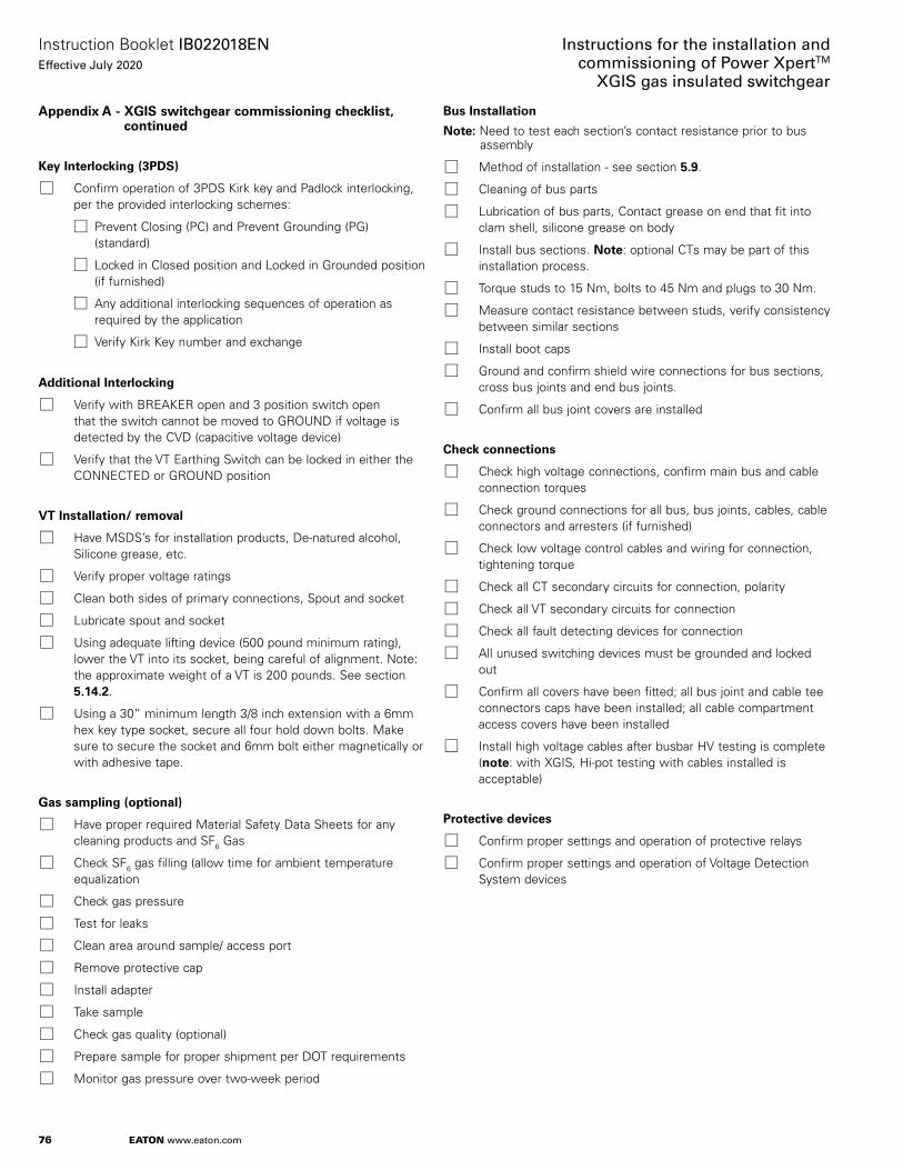
76
Instruction Booklet IB022018ENEffective July 2020
Instructions for the installation andcommissioning of Power XpertTM
XGIS gas insulated switchgear
EATON www.eaton.com
Appendix A - XGIS switchgear commissioning checklist, continued
Key Interlocking (3PDS)
Confirm operation of 3PDS Kirk key and Padlock interlocking, per the provided interlocking schemes:
Prevent Closing (PC) and Prevent Grounding (PG) (standard)
Locked in Closed position and Locked in Grounded position (if furnished)
Any additional interlocking sequences of operation as required by the application
Verify Kirk Key number and exchange
Additional Interlocking
Verify with BREAKER open and 3 position switch open that the switch cannot be moved to GROUND if voltage is detected by the CVD (capacitive voltage device)
Verify that the VT Earthing Switch can be locked in either the CONNECTED or GROUND position
VT Installation/ removal
Have MSDS’s for installation products, De-natured alcohol, Silicone grease, etc.
Verify proper voltage ratings
Clean both sides of primary connections, Spout and socket
Lubricate spout and socket
Using adequate lifting device (500 pound minimum rating), lower the VT into its socket, being careful of alignment. Note: the approximate weight of a VT is 200 pounds. See section 5.14.2.
Using a 30” minimum length 3/8 inch extension with a 6mm hex key type socket, secure all four hold down bolts. Make sure to secure the socket and 6mm bolt either magnetically or with adhesive tape.
Gas sampling (optional)
Have proper required Material Safety Data Sheets for any cleaning products and SF6 Gas
Check SF6 gas filling (allow time for ambient temperature equalization
Check gas pressure
Test for leaks
Clean area around sample/ access port
Remove protective cap
Install adapter
Take sample
Check gas quality (optional)
Prepare sample for proper shipment per DOT requirements
Monitor gas pressure over two-week period
Bus Installation
Note: Need to test each section’s contact resistance prior to bus assembly
Method of installation - see section 5.9.
Cleaning of bus parts
Lubrication of bus parts, Contact grease on end that fit into clam shell, silicone grease on body
Install bus sections. Note: optional CTs may be part of this installation process.
Torque studs to 15 Nm, bolts to 45 Nm and plugs to 30 Nm.
Measure contact resistance between studs, verify consistency between similar sections
Install boot caps
Ground and confirm shield wire connections for bus sections, cross bus joints and end bus joints.
Confirm all bus joint covers are installed
Check connections
Check high voltage connections, confirm main bus and cable connection torques
Check ground connections for all bus, bus joints, cables, cable connectors and arresters (if furnished)
Check low voltage control cables and wiring for connection, tightening torque
Check all CT secondary circuits for connection, polarity
Check all VT secondary circuits for connection
Check all fault detecting devices for connection
All unused switching devices must be grounded and locked out
Confirm all covers have been fitted; all bus joint and cable tee connectors caps have been installed; all cable compartment access covers have been installed
Install high voltage cables after busbar HV testing is complete (note: with XGIS, Hi-pot testing with cables installed is acceptable)
Protective devices
Confirm proper settings and operation of protective relays
Confirm proper settings and operation of Voltage Detection System devices

77
Instruction Booklet IB022018ENEffective July 2020
Instructions for the installation andcommissioning of Power XpertTM
XGIS gas insulated switchgear
EATON www.eaton.com
Appendix A - XGIS switchgear commissioning checklist, continued
Medium voltage energizing sequence
Confirm all panel doors are closed, all cable compartment access covers installed
Switch all CB off
Switch all 3PDS off
All panel doors are secured
Connect the incoming main sections
Switch on first panel 3PDS
Switch on first incoming main section panel CB. Busbar is now at operating voltage
Before connecting further incoming main sections, ensure that the phase angle of the panels is identical (for more than one incoming power source)
Connect the outgoing feeder sections (loads) when these are circuit breaker panels
Switch on 3PDS
Switch on CB
Connect the outgoing feeder sections (loads) when these are switch-disconnector panels with fuses:
Switch on 3PDS
VDS will indicate voltage present when the equipment is energized
Revise any circuit diagrams where installation and commissioning has resulted in changes to the design
Complete the commissioning records including schematics, wiring diagrams, etc. Make relevant copies (customer, DOC, Greenwood)
Confirm that project accessories have been transferred to the customer operators, engineers, etc.
Operating Manual
Project drawings and order documents
Kirk keys, door keys and padlock keys
3PDS manual operation T-handle
Earthing set (optional)
Plug-in indicator unit for capacitive indication – if necessary
Phase comparator in the case of more than one incoming feeder (optional)
Provide Operator instruction in the switchgear operation (theory and practice)

78
Instruction Booklet IB022018ENEffective July 2020
Instructions for the installation andcommissioning of Power XpertTM
XGIS gas insulated switchgear
EATON www.eaton.com
Notes:

79
Instruction Booklet IB022018ENEffective July 2020
Instructions for the installation andcommissioning of Power XpertTM
XGIS gas insulated switchgear
EATON www.eaton.com
Notes:

Eaton1000 Eaton BoulevardCleveland, OH 44122United StatesEaton.com
© 2020 EatonAll Rights ReservedPrinted in USAPublication No. IB022018EN / TBG 001430July 2020
Eaton is a registered trademark.
All other trademarks are property of their respective owners.
Instruction Booklet IB022018ENEffective July 2020
Instructions for the installation andcommissioning of Power Xpert™
XGIS gas insulated switchgear