instructions for installation, operation and maintenance ...pub/@electrical/documents/conte… ·...
TRANSCRIPT
IB14001
Instructions for Installation, Operation and Maintenance of the Eaton ATC-900 Open/Closed Transition Transfer Switch ControllerInstructional Booklet
2EN For more information visit
Description Page
1. Introduction . . . . . . . . . . . . . . . . . . . . . . . . . . . . . . . 22. Hardware Description . . . . . . . . . . . . . . . . . . . . . . . . 63. Operator Panel and Display Menus . . . . . . . . . . . . . . . 124. Operation . . . . . . . . . . . . . . . . . . . . . . . . . . . . . . . . . 155. Setpoint Programming and I/O Programming
Using the Color Display . . . . . . . . . . . . . . . . . . . . . . . . 186. Troubleshooting and Maintenance . . . . . . . . . . . . . . . . . 267. Historical & Event Display . . . . . . . . . . . . . . . . . . . . . 30
Appendix A: Feature List and Status Display Messages . 32Appendix B: I/O Descriptions . . . . . . . . . . . . . . . . . . . 41Appendix C: Operational Flowcharts . . . . . . . . . . . . . . 43
: www.eaton.com
Instructional BookletPage 2 Effective: June 2015 Instructions for Installation, Operation and Maintenance of the
Eaton ATC-900 Open/Closed Transition Transfer Switch Controller
All possible contingencies which may arise during installation, operation, or maintenance, and all details and variations of this equipment do not purport to be covered by these instructions. If further information is desired by purchaser regarding his particular installation, operation or maintenance of his equipment, the local Eaton representative should be contacted.
Eaton Disclaimer and Warning
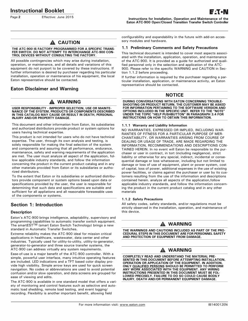
Section 1: IntroductionDescriptionEaton’s ATC-900 brings intelligence, adaptability, supervisory and programming capabilities to automatic transfer switch equipment. The smartESTTM (smart Eaton Switch Technology) brings a new standard in Automatic Transfer Switches.Extreme reliability makes the ATC-900 ideal for mission critical applications in healthcare, wastewater, data center and other industries. Typically used for utility-to-utility, utility-to-generator, generator-to-generator and three source transfer systems, the ATC-900 can address virtually any system requirements.Ease-of-use is a major benefit of the ATC-900 controller. With a simple, powerful user interface, many intuitive operating features are included. LED indications and a TFT based color display pro-vide high visibility. Simple arrow keys are used for quick screen navigation. No codes or abbreviations are used to avoid potential confusion and/or slow operation, and data screens are grouped for ease of viewing and edits. The ATC-900 is available in one standard model that offers a vari-ety of monitoring and control features such as selective and auto-matic load shedding, remote load testing, and event logging/recording. Flexibility is another important benefit, allowing field
configurability and expandability in the future with add-on acces-sory modules and hardware.
1.1 Preliminary Comments and Safety PrecautionsThis technical document is intended to cover most aspects associ-ated with the installation, application, operation, and maintenance of the ATC-900. It is provided as a guide for authorized and quali-fied personnel only in the selection and application of the ATC-900. Please refer to the specific WARNING and CAUTION in Sec-tion 1.1.2 before proceeding. If further information is required by the purchaser regarding a par-ticular installation, application, or maintenance activity, an Eaton representative should be contacted.
1.1.1 Warranty and Liability InformationNO WARRANTIES, EXPRESSED OR IMPLIED, INCLUDING WAR-RANTIES OF FITNESS FOR A PARTICULAR PURPOSE OF MER-CHANTABILITY, OR WARRANTIES ARISING FROM COURSE OF DEALING OR USAGE OF TRADE, ARE MADE REGARDING THE INFORMATION, RECOMMENDATIONS AND DESCRIPTIONS CON-TAINED HEREIN. In no event will Eaton be responsible to the pur-chaser or user in contract, in tort (including negligence), strict liability or otherwise for any special, indirect, incidental or conse-quential damage or loss whatsoever, including but not limited to damage or loss of use of equipment, plant or power system, cost of capital, loss of power, additional expenses in the use of existing power facilities, or claims against the purchaser or user by its cus-tomers resulting from the use of the information and descriptions contained herein. analyze all aspects of the application,follow applicable industry standards, and follow the information concern-ing the product in the current product catalog and in any other materials
1.1.2 Safety PrecautionsAll safety codes, safety standards, and/or regulations must be strictly observed in the installation, operation, and maintenance of this device.
CAUTIONTHE ATC-900 IS FACTORY PROGRAMMED FOR A SPECIFIC TRANS-FER SWITCH. DO NOT ATTEMPT TO INTERCHANGE ATC-900 CON-TROL DEVICES WITHOUT CONSULTING THE FACTORY.
WARNINGUSER RESPONSIBILITY - IMPROPER SELECTION, USE OR MAINTE-NANCE OF THE SYSTEM, PRODUCTS OR COMPONENTS DESCRIBED IN THIS CATALOG MAY CAUSE OR RESULT IN DEATH, PERSONAL INJURY AND/OR PROPERTY DAMAGE.
This document and other information from Eaton, its subsidiaries and authorized distributors provide product or system options for users having technical expertise. This product is not intended for users who do not have technical expertise. The user, through its own analysis and testing, is solely responsible for making the final selection of the system and components and assuring that all performance, endurance, maintenance, safety and warning requirements of the application are met. The user must analyze all aspect of the application, fol-low applicable industry standards, and follow the information concerning the product in the current product catalog and in any other materials provided from Eaton or its subsidiaries or autho-rized distributors. To the extent that Eaton or its subsidiaries or authorized distribu-tors provide component or system options based upon data or specifications provided by the user, the user is responsible for determining that such data and specifications are suitable and sufficient for all appliations and all reasonable foreseeable uses of the components or systems.
NOTICEDURING CONVERSATIONS WITH EATON CONCERNING TROUBLE-SHOOTING OR PRODUCT RETURN, THE CUSTOMER MAY BE ASKED FOR INFORMATION PERTAINING TO THE SOFTWARE VERSION AND OPTIONS INCLUDED IN THE SPECIFIC UNIT. REFER TO THE “NOTE” UNDER THE TOPIC “HELP PUSHBUTTON” IN PARAGRAPH 3.4 FOR INSTRUCTIONS ON HOW TO OBTAIN THIS INFORMATION.
WARNINGTHE WARNINGS AND CAUTIONS INCLUDED AS PART OF THE PRO-CEDURAL STEPS IN THIS DOCUMENT ARE FOR PERSONNEL SAFETY AND PROTECTION OF EQUIPMENT FROM DAMAGE.
WARNINGCOMPLETELY READ AND UNDERSTAND THE MATERIAL PRE-SENTED IN THIS DOCUMENT BEFORE ATTEMPTING INSTALLATION, OPERATION OR APPLICATION OF THE EQUIPMENT. IN ADDITION, ONLY QUALIFIED PERSONS SHOULD BE PERMITTED TO PERFORM ANY WORK ASSOCIATED WITH THE EQUIPMENT. ANY WIRING INSTRUCTIONS PRESENTED IN THIS DOCUMENT MUST BE FOL-LOWED PRECISELY. FAILURE TO DO SO COULD CAUSE BODILY INJURY, DEATH AND/OR PERMANENT EQUIPMENT DAMAGE.
For more information visit: www.eaton.com IB140012EN
Instructional BookletEffective: June 2015 Page 3Instructions for Installation, Operation and Maintenance of the
Eaton ATC-900 Open/Closed Transition Transfer Switch Controller
1.2 BackgroundTransfer switches are used to protect critical electrical loads against loss of power. The load’s normal power source is backed up by a secondary (emergency) power source. A transfer switch is connected to both the normal and emergency sources and sup-plies the load with power from one of these two sources. In the event that power is lost from the normal source, the transfer switch transfers the load to the secondary source. Transfer can be automatic or manual depending upon the type of transfer switch equipment being used. Once normal power is restored, the load is transferred back to the normal power source. The transfer switch, in this manual, could be a Case Switch/Breaker, Molded Case Switch/Breaker, or a Contactor type.In automatic transfer switch equipment, the switch’s intelligence system initiates the transfer when normal power fails or falls below a preset voltage. If the emergency source is a standby gen-erator, the transfer switch initiates generator starting and trans-fers to the emergency source when sufficient generator voltage is available. When normal power is restored, the transfer switch automatically transfers back and initiates generator engine shut-down.An automatic transfer switch consists of three basic elements:
1. Main contacts to connect and disconnect the load to and from the source of power
2. A transfer mechanism to affect the transfer of the main con-tacts from source to source
3. Intelligence/supervisory circuits to constantly monitor the con-dition of the power sources and thus provide the intelligence necessary for the switch and related circuit operation
This document deals with the third basic element of the automatic transfer switch, the required intelligence/ supervisory circuits. Prior to the introduction of ATC-900, this function was performed by a door mounted logic panel. The logic panel could be the relay logic type or the solid state logic type. In either case, the panel consists of a number of individually mounted and wired devices offering a limited amount of system flexibility, especially in the case of the relay logic design. The ATC-900 brings intelligence, supervisory and programming capabilities, never before available, to automatic transfer switch equipment.
1.3 Product OverviewThe ATC-900 is a comprehensive, multi-function, microprocessor- based automatic transfer switch controller. It is a compact, self-contained, panel mounted device designed to replace traditional relay and solid state logic panels (Figures 2 and 3).Designed to meet the needs of markets worldwide, the ATC-900 meets the following standards:
• ULT 991 Effects of shipping and storage test• Thermal cycling test• Humidity test• UL 1008 Dielectric test• FCC Part 15 Conducted/radiated emissions (Class A)• CISPR 11 Conducted/radiated emissions (Class A)• IEC 61000-4-2 Electrostatic discharge test• IEC 61000-4-3 Radiated susceptibility tests• IEC 61000-4-4 Fast transient tests• IEC 61000-4-5 Surge withstand tests• IEC 61000-4-6 Conducted immunity tests• IEC 61000-4-11 Voltage dips and interruptions• IEC 61000-3-2 Harmonics
• IEC 61000-3-3 Voltage flicker/fluctuation• Seismic IBC/CBC certified• CSAT conformance C22.2 No. 178-1978 (reaffirmed 1992)• European standards conformance (CE mark)
The ATC-900 provides an unmatched degree of programmed flexi-bility to address the needs of any system. It operates from most system voltages available worldwide at 50 or 60 Hertz (and 24 VDC using the CT Module option). In addition, a period of no con-trol power operation is provided. The ATC-900 monitors the condi-tion of the 3-phase line-to-line voltage and frequency of both the Normal and Emergency sources. It can also be programmed for sin-gle-phase operation. The ATC-900 provides the necessary intelli-gence to insure that the switch operates properly through a series of programmed sensing and timing functions.The ATC-900 will form fit into the opening of the ATC-600/800 and an easy upgrade kit is available for previous switch wiring.
A standard ATC-900 will:• Monitor Normal and Emergency source voltages and frequen-
cies• Provide second to none Event Summary, Hi-Speed Capture, and
History information• Permit customer programming including I/O• Display real time and historical information through a color 4.5
inch TFT display• System diagnostics through the display• All I/O are available to the user• Features are opened to user• Communicate using a MODBUS-485, Ethernet (not standard),
and USB• Provide faceplate source/load status indications (MIMIC bus)
1.4 Functions/Features/OptionsThe primary function of ATC-900 is to accurately monitor power sources and provide the necessary intelligence to operate a trans-fer switch in an appropriate and timely manner. In addition, ATC-900 provides useful present and historical data, reliable two-way communications, and programming through the device’s face-plate or communications. ATC-900 features digital signal proces-sor (DSP) technology to provide and maintain superior precision and versatility during both programming and data access.
1.4.1 Operational SimplicityFrom installation, to programming, to usage, the ATC-900 was designed with operational simplicity in mind. Only one style needs to be considered, regardless of input/output requirements or sys-tem voltages and frequencies. ATC-900 provides the functionality of numerous other devices combined in one package that mounts in less than 7 by 11 inches of panel space.The user friendly front panel interface simplifies routine operation, programming, data presentation and setting adjustments. A large color display provides flexibility and ease of use. The operation of front panel membrane pushbuttons moves the ATC-900 display from function to function or step to step within menus. A single LED at the top of the faceplate provide an immediate indication as to the device’s operational mode. An integrated Help Mode provides immediate user assistance in the form of English language message displays through the use of a front panel Help pushbutton.The ATC-900 is communications ready, including Modbus 485, Ethernet (External), and USB for thumb drives (memory sticks).
IB140012EN For more information visit: www.eaton.com
Instructional BookletPage 4 Effective: June 2015 Instructions for Installation, Operation and Maintenance of the
Eaton ATC-900 Open/Closed Transition Transfer Switch Controller
1.4.2 Standard and Optional FeaturesA variety of programmable features are available to meet a wide array of application requirements. Individual features or feature combinations provide the information required to tailor switches to individual needs.Unlike earlier controllers, the ATC-900 comes with standard fea-tures that are ready to use, with the exception of Closed Transi-tion, Current metering, and Ethernet. Another advancement is that there are four (4) standard inputs and four (4) standard outputs that the operator can easily program by choosing from a wide array of predefined functions. Additional inputs and outputs can be added in groups of four (4) up to sixteen (16) for a maximum of twenty (20) in total. The inputs are DC wetted (24 Volts at 10 ma) connections for various functional inputs.
1.5 Glossary of Terms and Features
AvailableA source is defined as available when it is within its undervoltage/overvoltage/underfrequency/overfrequency (if applicable) setpoint ranges for the nominal voltage and frequency setting.
Unavailable A source is defined as failed when it is outside of its undervoltage/overvoltage/underfrequency/overfrequency (if applicable) setpoint ranges for the nominal voltage and frequency setting.
Normal SourceThe Normal Source is defined as the source that is preferred. The Preferred Source setting allows the operator to select Source 1, Source 2 or NONE as the Preferred Source. If NONE is chosen, the Preferred Source or the Normal Source will be the source that is presently attached to the load. The default is set as being Source 1 as the Preferred and Normal Source.
Emergency SourceThe Emergency Source is defined as the source that is not pre-ferred. If NONE is chosen for the Preferred Source setting, the Emergency Source will be the source that is presently not attached to the load. Therefore, in this condition after a transfer, the Normal and Emergency Sources will switch between Source 1 and 2.
1.5.1 FeaturesThe ATC-900 has many features that are available to the user. These features are standard and are available depending on the type of transfer switch used (i.e. Contactor, Power Case Switch/Breaker, or Molded Case Switch/Breaker, 2 or 3 position). Appen-dix A has a list of all of the features including any acronyms used along with a brief description. The feature numbers corresponds to the internal codes and some of these numbers may be on the product drawings. See Table 5 "ATC-900 Features" for a compact list of features, including a full list of available I/O. Consult Appendix B for I/O descriptions. For some transfer switch configu-rations, standard input(s) and/or standard output(s) will be fixed at the factory to support system functionality and will not be pro-grammable in the field. An example of this is Service Entrance; which requires Go To Neutral to be a fixed input. The programma-ble I/Os are covered in Section 5.The only item that is optional for the transfer switch is the closed transition optional feature. The closed transition operation is cov-ered in section 1.5.3
The switch type also dictates what can be programmed. For example, a two position contactor switch cannot have feature TDN (Time Delay Neutral), as it has no neutral position available. A motor MCS/MCCB type transfer switch with motor operator cannot have closed transition as the switching mechanism is not fast enough and will not meet the time line.
1.5.2 In-Phase Operation
The In-Phase operation of an Automatic Transfer Switch is an open type transfer. It will allow a transfer between two available sources if the phase angle has a difference of eight degrees or less. Appendix A (32C, 32D, 32F) shows detailed descriptions of the different scenarios that can be performed using In-Phase.
As shown in the feature list of Appendix A for In-Phase, there are three scenarios for In-Phase:
32C= In-Phase default to Load Voltage Decay32D= In-Phase default to Time Delay Neutral32F= In-Phase
The user setpoints for In-phase transition are similar to this:• Disabled (In-Phase not used)• Alarm on Synchronization Fail (Will not switch and will show
an alarm)• Fallback to Open on Synchronization Fail (To TDN or LVD)
For example, with the setpoint at Fallback, using a two position contactor, the switch will transfer, if no synchronisation occurs, to the other source. The three position will allow the use of TDN. A two or three position could also use Load Voltage Decay.
1.5.3 Closed Transition Operation
Several Options for Closed TransitionOnce an ATS is in the field, other uses or changes may occur that could require changes from the original requirements. One area is the closed transition type switches. An application may initially require that only a closed transition should be used and if it does not synchronize because of maybe frequency, then the switch will not switch to the other source and will show an alarm signalling this issue. If the requirements now have change, for example, and the switch must now transfer using open transition if closed does not occur; instead of sending the controller back to the factory for reprogramming, one can easily change the user setpoints to accomplish any scenario. One may go from closed transition directly to Time Delay Neutral for example. All options are avail-able to the user.If closed transition is available on the switch, the user will receive 47 D and all of the other options 47 C, E, F, G which can be changed by the setpoints to disable or enable the functions (see below). Screen 3 of 3 in the System Setup menu (See section 3.4.1) is where the user will set the transition types of the switch. If the switch can perform closed transition the user will set up the setpoints depending on the scenario required as shown below.
Closed Transition to Alarm (47D) or by changing the setpoints, Closed Transition > In-Phase > TDN Closed Transition > In-Phase > LVDClosed Transition > TDNClosed Transition > LVD
The user can disable closed transition and just use the following:In-Phase > TDN In-Phase > LVD
Also with Closed Transition and In-Phase disabled:TDN or LVD
NOTICEWITH RESPECT TO THEIR USE IN THIS DOCUMENT AND AS THEY RELATE TO AUTOMATIC TRANSFER SWITCH OPERATION, THE FOL-LOWING WORDS OR PHRASES ARE DEFINED.
For more information visit: www.eaton.com IB140012EN

Instructional BookletEffective: June 2015 Page 5Instructions for Installation, Operation and Maintenance of the
Eaton ATC-900 Open/Closed Transition Transfer Switch Controller
The user setpoints for closed transition are similar to this:• Disabled (Closed transition not used)• Alarm on Synchronization Fail (Will not switch and will show
an alarm)• Fallback to Open on Synchronization Fail (To in-phase, TDN,
and/or LVD)
Optional Feature 47C: Closed/In-phase Transition/Load Voltage DecayClosed Transition is a feature that will temporarily parallel two live sources in a make-before-break scheme when performing a trans-fer. This achieves a transfer between sources with no power interruption. Both sources must be synchronized in frequency, phase, and voltage before the transfer is initiated. In-phase transition is a feature that will allow a transfer between two live sources only when the phase difference between the two sources is near zero. This is an open transition transfer that pre-vents in-rush currents from exceeding normal starting currents in the case where motor loads are being transferred.Load Voltage Decay utilizes the load voltage measurements to sense back EMF that is generated when the transfer switch is in the neutral position. It provides a delay in transfer in either direc-tion if an unacceptable level is sensed as established by a cus-tomer programmed level. The transfer will not take place until the back EMF decays below the acceptable programmed level. This feature has a separate setting of enabling or disabling the opera-tion. If disabled, the transfer switch will not delay in the neutral position and will transfer between the sources as fast as possible.
Optional Feature 47D: Closed Transition OnlyClosed Transition is a feature that will temporarily parallel two live sources in a make-before-break scheme when performing a trans-fer. This achieves a transfer between sources with no power interruption. Both sources must be synchronized in frequency, phase, and voltage before the transfer is initiated. If the two avail-able sources do not synchronize in a certain settable sync time, the switch will not transfer and an output alarm will be present as well as a red flashing banner on the controller stating; Failed to Sync -(Frequency, Voltage, or Phase angle)If the logic is forced into a fail safe mode (i.e. loss of connected source), the logic will perform an open transfer.
Optional Feature 47E: Closed/In-Phase Transition/Time Delay NeutralClosed Transition is a feature that will temporarily parallel two live sources in a make-before-break scheme when performing a trans-fer. This achieves a transfer between sources with no power interruption. Both sources must be synchronized in frequency, phase, and voltage before the transfer is initiated. In-phase transition is a feature that will allow a transfer between two live sources only when the phase difference between the two sources is near zero. This is an open transition transfer that pre-vents in-rush currents from exceeding normal starting currents in the case where motor loads are being transferred.Time delay neutral provides a time delay in the transfer switch neutral position when both breakers/contactors are open. This delay takes place when the load is transferred in either direction to prevent excessive in-rush currents due to out of phase switching of large motor loads.
Optional Feature 47F: Closed/Load Voltage DecayClosed Transition is a feature that will temporarily parallel two livesources in a make-before-break scheme when performing a trans-fer. This achieves a transfer between sources with no power inter-ruption. Both sources must be synchronized in frequency, phase, and voltage before the transfer is initiated.Time Delay Load Voltage Decay utilizes the load voltage measure-ments to sense back EMF that is generated when the transfer switch is in the neutral position. It provides a delay in transfer in either direction if an unacceptable level is sensed as established by a customer programmed level. The transfer will not take place until the back EMF decays below the acceptable programmed level. This feature has a separate setting of enabling or disabling the operation. If disabled, the transfer switch will not delay in the neutral position and will transfer between the sources as fast as possible.
Optional Feature 47G: Closed/Time Delay NeutralClosed Transition is a feature that will temporarily parallel two live sources in a make-before-break scheme when performing a trans-fer. This achieves a transfer between sources with no power inter-ruption. Both sources must be synchronized in frequency, phase, and voltage before the transfer is initiated.Time delay neutral provides a time delay in the transfer switch neutral position when both breakers/contactors are open. This delay takes place when the load is transferred in either direction to prevent excessive in-rush currents due to out of phase switching of large motor loads.
Optional Feature 29G: Type of Operation (Selectable Automatic or Manual)This feature provides two door mounted selector switches marked Auto/Manual and S1-Trip-S2 which permits the selection of auto-matic or manual operation. In manual operation, the user can man-ually initiate and electrically operate between S1, Trip, or S2. On the Contactor Bypass's, 29G uses the top switch and the bottom switch. See the switch instruction booklet for operating instruc-tions. The controller is in Monitor Mode during the manual opera-tion meaning the controller will not attempt to change the switch position but will monitor the voltage availability and the switch positions. The ATC-900's display will show "MONITOR".
IB140012EN For more information visit: www.eaton.com

Instructional BookletPage 6 Effective: June 2015 Instructions for Installation, Operation and Maintenance of the
Eaton ATC-900 Open/Closed Transition Transfer Switch Controller
Section 2: Hardware Description2.1 GeneralThe purpose of this section is to familiarize the reader with ATC-900 hardware, its nomenclature, and to list the unit’s specifica-tions. The information presented is divided into the following four parts:• Operator Panel; • Rear Access Area; • External Hardware; and• Specification Summary.
2.2 Operator PanelThe operator panel, which is normally accessible from the outside of a panel or door, provides a means for:• Being alerted to specific conditions; • Receiving functional help; • Programming; and• Parameter Monitoring/Selection/Metering.LEDs, a display, pushbuttons, and a mimic bus make up the front accessible operator panel (Figure 1).The Color high resolution TFT LCD is used to display all ATC-900 monitored parameters, setpoints and messages in an easy to read format. The display is approximately 2.25" x 4" (57.15mm x 101.6mm). The TFT display is not a touch screen.The front operator panel supports seven long-life extended tem-perature membrane pushbuttons.
2.3 Rear Access AreaThe rear access area of the ATC-900 is normally accessible from the rear of an open switch panel door (Figure 2).All wiring connections to the ATC-900 are made at the rear of the chassis. For the sake of uniform identification, the frame of refer-ence when discussing the rear access area is facing the back of the ATC-900 with the panel door open. Keeping safety in mind, programming and downloading setpoints, history, and events can all be accomplished with the front door closed. A USB connector with a cover is brought out from the back of the controller to the front of the door on the switch using the device panel.
2.3.1 Connections on ChassisThe rear of the chassis provides self locking female connectors. See Figure 2 for connections for the left, right, and top of the ATC-900. See Section 4 for more information on input functional-ity. The part numbers of the connectors are shown below:
Connector DesignationJ1 Source 1 Sense Lines
J2 Source 2 Sense Lines
J3 Load Sense Lines
J4 Programmable Outputs (4) & Source Available Form C
J5 RS-232 (Factory Use)
J6 Transfer Control and Aux Inputs
J7 Control Power from Sources 1 and 2
J8 USB Stick (thumb) Drive Connection (connector brought out to front door panel)
J9 Programmable Inputs (4)
J11 I/O Module Interface
J12 Modbus 485 (User)
J13 RS-422
J14 DCT Module Interface
For more information visit: www.eaton.com IB140012EN
Instructional BookletEffective: June 2015 Page 7Instructions for Installation, Operation and Maintenance of the
Eaton ATC-900 Open/Closed Transition Transfer Switch Controller
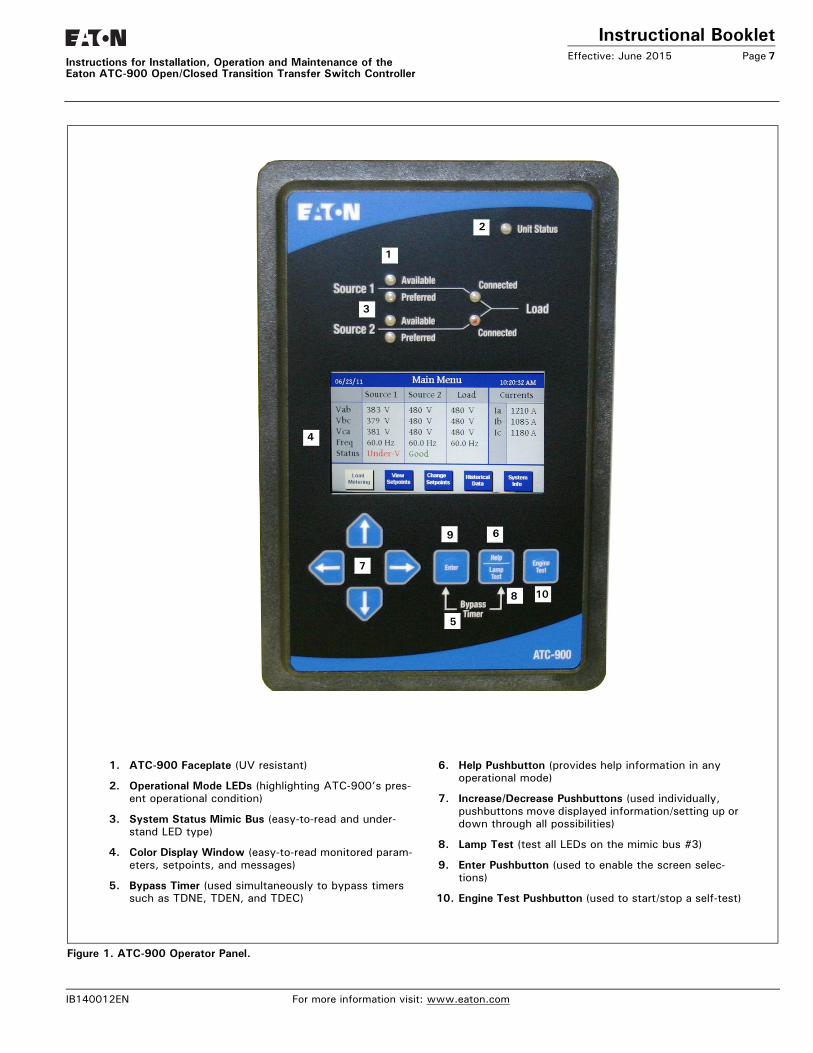
Figure 1. ATC-900 Operator Panel.
1. ATC-900 Faceplate (UV resistant)
2. Operational Mode LEDs (highlighting ATC-900’s pres-ent operational condition)
3. System Status Mimic Bus (easy-to-read and under-stand LED type)
4. Color Display Window (easy-to-read monitored param-eters, setpoints, and messages)
5. Bypass Timer (used simultaneously to bypass timers such as TDNE, TDEN, and TDEC)
6. Help Pushbutton (provides help information in any operational mode)
7. Increase/Decrease Pushbuttons (used individually, pushbuttons move displayed information/setting up or down through all possibilities)
8. Lamp Test (test all LEDs on the mimic bus #3)
9. Enter Pushbutton (used to enable the screen selec-tions)
10. Engine Test Pushbutton (used to start/stop a self-test)
2
1
3
4
5
6
7
108
9
IB140012EN For more information visit: www.eaton.com
Instructional BookletPage 8 Effective: June 2015
Instructions for Installation, Operation and Maintenance of theEaton ATC-900 Open/Closed Transition Transfer Switch Controller
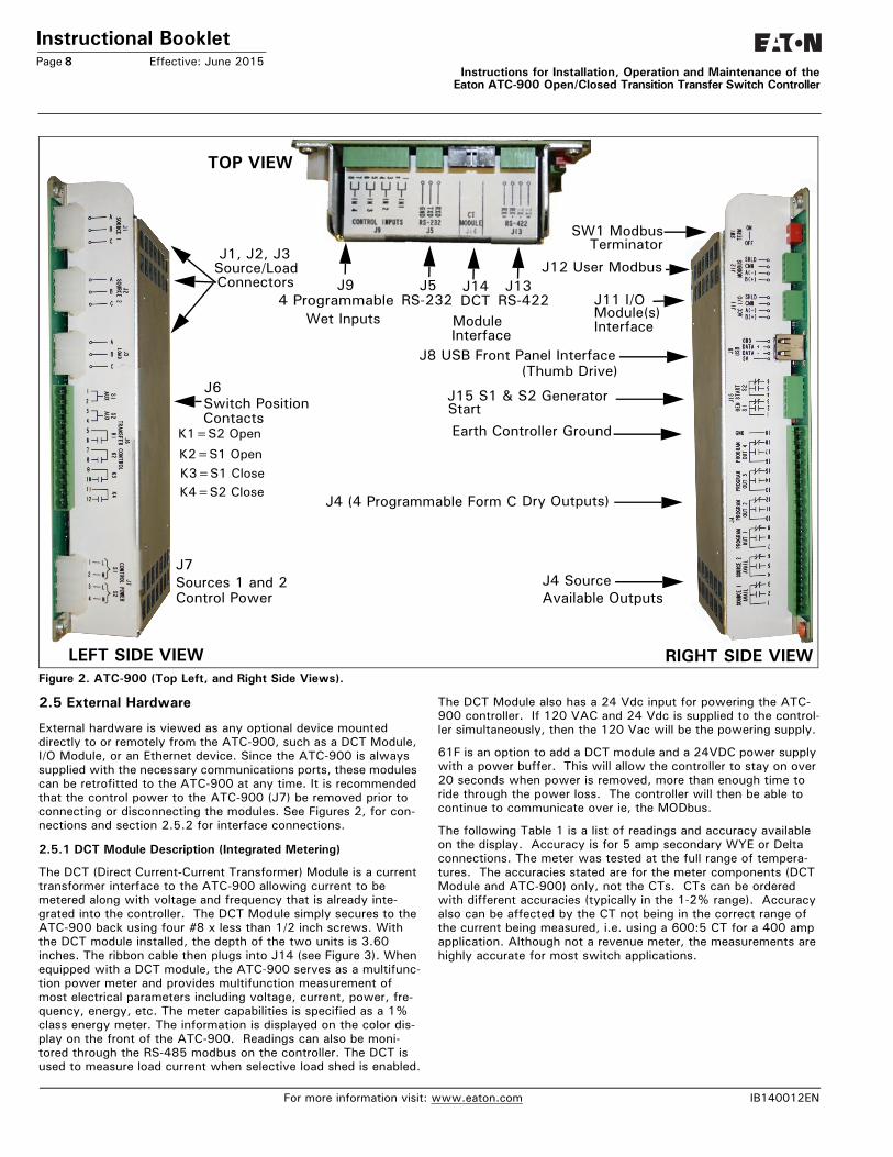
Figure 2. ATC-900 (Top Left, and Right Side Views).
2.5 External Hardware
External hardware is viewed as any optional device mounted directly to or remotely from the ATC-900, such as a DCT Module, I/O Module, or an Ethernet device. Since the ATC-900 is always supplied with the necessary communications ports, these modules can be retrofitted to the ATC-900 at any time. It is recommended that the control power to the ATC-900 (J7) be removed prior to connecting or disconnecting the modules. See Figures 2, for con-nections and section 2.5.2 for interface connections.
2.5.1 DCT Module Description (Integrated Metering)
The DCT (Direct Current-Current Transformer) Module is a current transformer interface to the ATC-900 allowing current to be metered along with voltage and frequency that is already inte-grated into the controller. The DCT Module simply secures to the ATC-900 back using four #8 x less than 1/2 inch screws. With the DCT module installed, the depth of the two units is 3.60 inches. The ribbon cable then plugs into J14 (see Figure 3). When equipped with a DCT module, the ATC-900 serves as a multifunc-tion power meter and provides multifunction measurement of most electrical parameters including voltage, current, power, fre-quency, energy, etc. The meter capabilities is specified as a 1% class energy meter. The information is displayed on the color dis-play on the front of the ATC-900. Readings can also be moni-tored through the RS-485 modbus on the controller. The DCT is used to measure load current when selective load shed is enabled.
The DCT Module also has a 24 Vdc input for powering the ATC-900 controller. If 120 VAC and 24 Vdc is supplied to the control-ler simultaneously, then the 120 Vac will be the powering supply.
61F is an option to add a DCT module and a 24VDC power supply with a power buffer. This will allow the controller to stay on over 20 seconds when power is removed, more than enough time to ride through the power loss. The controller will then be able to continue to communicate over ie, the MODbus.
The following Table 1 is a list of readings and accuracy available on the display. Accuracy is for 5 amp secondary WYE or Delta connections. The meter was tested at the full range of tempera-tures. The accuracies stated are for the meter components (DCT Module and ATC-900) only, not the CTs. CTs can be ordered with different accuracies (typically in the 1-2% range). Accuracy also can be affected by the CT not being in the correct range of the current being measured, i.e. using a 600:5 CT for a 400 amp application. Although not a revenue meter, the measurements are highly accurate for most switch applications.
RIGHT SIDE VIEWLEFT SIDE VIEW
J15 S1 & S2 GeneratorStart
J4 (4 Programmable Form C Dry Outputs)
J5
J1, J2, J3
ConnectorsJ12 User Modbus
K1=S2 Open
K2=S1 OpenK3=S1 CloseK4=S2 Close
J7
Control PowerSources 1 and 2
TOP VIEW
J4 Source Available Outputs
J9 4 Programmable
Wet Inputs
J6
RS-232 J14DCT
Earth Controller Ground
J8 USB Front Panel Interface(Thumb Drive)
J11 I/O Module(s)
SW1 ModbusTerminator
Module
J13RS-422
Interface
Source/Load
Interface
Switch Position Contacts
For more information visit: www.eaton.com IB140012EN
Instructional BookletEffective: June 2015 Page 9
Instructions for Installation, Operation and Maintenance of the Eaton ATC-900 Open/Closed Transition Transfer Switch Controller
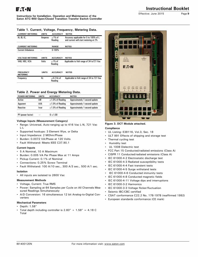
Table 1. Current, Voltage, Frequency, Metering Data.
Table 2. Power and Energy Metering Data.
Voltage Inputs (Measurement Category)• Range: Universal, Auto-ranging up to 416 Vac L-N, 721 Vac
L-L• Supported hookups: 3 Element Wye, or Delta• Input Impedance: 2 MOhm/Phase• Burden: 0.0072 VA/Phase at 120 Volts• Fault Withstand: Meets IEEE C37.90.1
Current Inputs• 5 A Nominal, 10 A Maximum• Burden: 0.005 VA Per Phase Max at 11 Amps• Pickup Current: 0.1% of Nominal• Connections: 0.25% Screw Terminal• Fault Withstand: 100 A/10 sec., 300 A/3 sec., 500 A/1 sec.
Isolation• All inputs are isolated to 2600 Vac
Measurement Methods• Voltage, Current: True RMS• Power: Sampling at 64 Samples per Cycle on All Channels Mea-
sured Readings Simultaneously• A/D Conversion: 16 simultaneous 12 bit Analog-to-Digital Con-
verters
Mechanical Parameters• Depth: 1.58"• Total depth including controller is 2.60" + 1.58" = 4.18 C
Total
Figure 3. DCT Module attached.
Compliance• UL Listing: E38116, Vol.3, Sec. 18• ULT 991 Effects of shipping and storage test• Thermal cycling test• Humidity test• UL 1008 Dielectric test• FCC Part 15 Conducted/radiated emissions (Class A)• CISPR 11 Conducted/radiated emissions (Class A)• IEC 61000-4-2 Electrostatic discharge test• IEC 61000-4-3 Radiated susceptibility tests• IEC 61000-4-4 Fast transient tests• IEC 61000-4-5 Surge withstand tests• IEC 61000-4-6 Conducted immunity tests• IEC 61000-4-8 Conducted magnetic fields• IEC 61000-4-11 Voltage dips and interruptions• IEC 61000-3-2 Harmonics• IEC 61000-3-3 Voltage flicker/fluctuation• Seismic IBC/CBC certified• CSAT conformance C22.2 No. 178-1978 (reaffirmed 1992)• European standards conformance (CE mark)
CURRENT METERING UNITS ACCURACY NOTES
lA, lB, IC, Amperes ±1% of Reading
Accuracy applicable for 5 to 100% of I, and current will start metering at 2%
CURRENT METERING RANGE NOTES
Current Unbalance -- 0-100%
VOLTAGE METERING UNITS ACCURACY NOTES
VAB, VBC, VCA Volts ±1% of Reading
Applicable to Volt range of 34 to721 Vac
FREQUENCY METERING
UNITS ACCURACY NOTES
Frequency Hz ±0.2 Hz of Reading
Applicable to Volt range of 34 to 721 Vac
POWER METERING UNITS ACCURACY NOTES
Active kW ±1.5% of Reading Approximately 1-second update
Apparent kVA ±1.5% of Reading Approximately 1-second update
Reactive kvar ±1.5% of Reading Approximately 1-second update
PF (power factor) --- 0-±1.00
IB140012EN For more information visit: www.eaton.com
Instructional BookletPage 10 Effective: June 2015 Instructions for Installation, Operation and Maintenance of the
Eaton ATC-900 Open/Closed Transition Transfer Switch Controller
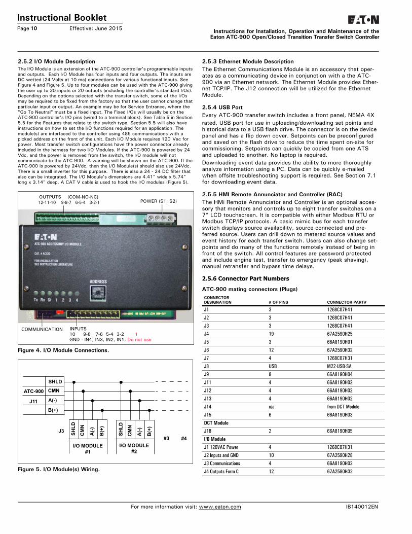
2.5.2 I/O Module DescriptionThe I/O Module is an extension of the ATC-900 controller's programmable inputs and outputs. Each I/O Module has four inputs and four outputs. The inputs are DC wetted (24 Volts at 10 ma) connections for various functional inputs. See Figure 4 and Figure 5. Up to four modules can be used with the ATC-900 giving the user up to 20 inputs or 20 outputs (including the controller's standard I/Os). Depending on the options selected with the transfer switch, some of the I/Os may be required to be fixed from the factory so that the user cannot change that particular input or output. An example may be for Service Entrance, where the "Go To Neutral" must be a fixed input. The Fixed I/Os will usually be on the ATC-900 controller's I/O pins (wired to a terminal block). See Table 5 in Section 5.5 for the Features that relate to the switch type. Section 5.5 will also have instructions on how to set the I/O functions required for an application. The module(s) are interfaced to the controller using 485 communications with a picked address on the front of the unit. Each I/O Module requires 120 Vac for power. Most transfer switch configurations have the power connector already included in the harness for two I/O Modules. If the ATC-900 is powered by 24 Vdc, and the power is removed from the switch, the I/O module will not communicate to the ATC-900. A warning will be shown on the ATC-900. If the ATC-900 is powered by 24Vdc, then the I/O Module(s) should also use 24Vdc. There is a small inverter for this purpose. There is also a 24 - 24 DC filter that also can be integrated. The I/O Module's dimensions are 4.41" wide x 5.74" long x 3.14" deep. A CAT V cable is used to hook the I/O modules (Figure 5).
Figure 4. I/O Module Connections.
Figure 5. I/O Module(s) Wiring.
2.5.3 Ethernet Module DescriptionThe Ethernet Communications Module is an accessory that oper-ates as a communicating device in conjunction with a the ATC-900 via an Ethernet network. The Ethernet Module provides Ether-net TCP/IP. The J12 connection will be utilized for the Ethernet Module.
2.5.4 USB PortEvery ATC-900 transfer switch includes a front panel, NEMA 4Xrated, USB port for use in uploading/downloading set points and historical data to a USB flash drive. The connector is on the device panel and has a flip down cover. Setpoints can be preconfigured and saved on the flash drive to reduce the time spent on-site for commissioning. Setpoints can quickly be copied from one ATS and uploaded to another. No laptop is required.Downloading event data provides the ability to more thoroughly analyze information using a PC. Data can be quickly e-mailed when offsite troubleshooting support is required. See Section 7.1 for downloading event data.
2.5.5 HMI Remote Annunciator and Controller (RAC)The HMi Remote Annunciator and Controller is an optional acces-sory that monitors and controls up to eight transfer switches on a 7” LCD touchscreen. It is compatible with either Modbus RTU or Modbus TCP/IP protocols. A basic mimic bus for each transfer switch displays source availability, source connected and pre-ferred source. Users can drill down to metered source values and event history for each transfer switch. Users can also change set-points and do many of the functions remotely instead of being in front of the switch. All control features are password protected and include engine test, transfer to emergency (peak shaving), manual retransfer and bypass time delays.
2.5.6 Connector Part Numbers
ATC-900 mating connectors (Plugs)
OUTPUTS (COM-NO-NC)12-11-10 9-8-7 6-5-4 3-2-1 POWER (S1, S2)
COMMUNICATION INPUTS 10 9-8 7-6 5-4 3-2 1GND - IN4, IN3, IN2, IN1, Do not use
SHLD
CMN
A(-)
B(+)
ATC-900
J11
SHLD
CM
N
A(-)
B(+
)
SHLD
CM
N
A(-)
B(+
)
I/O MODULE#1
I/O MODULE#2
J3#3 #4
CONNECTOR DESIGNATION # OF PINS CONNECTOR PART#
J1 3 1268C07H41
J2 3 1268C07H41
J3 3 1268C07H41
J4 19 67A2590H25
J5 3 66A8190H01
J6 12 67A2590H32
J7 4 1268C07H31
J8 USB M22-USB-SA
J9 8 66A8190H04
J11 4 66A8190H02
J12 4 66A8190H02
J13 4 66A8190H02
J14 n/a from DCT Module
J15 6 66A8190H03
DCT Module
J18 2 66A8190H05
I/O Module
J1 120VAC Power 4 1268C07H31
J2 Inputs and GND 10 67A2590H28
J3 Communications 4 66A8190H02
J4 Outputs Form C 12 67A2590H32
For more information visit: www.eaton.com IB140012EN
Instructional BookletEffective: June 2015 Page 11
Instructions for Installation, Operation and Maintenance of the Eaton ATC-900 Open/Closed Transition Transfer Switch Controller
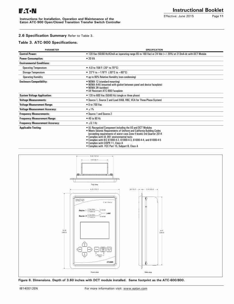
2.6 Specification Summary Refer to Table 3.
Table 3. ATC-900 Specifications.
Figure 6. Dimensions. Depth of 3.60 inches with DCT module installed. Same footprint as the ATC-600/800.
PARAMETER SPECIFICATION
Control Power: • 120 Vac (50/60 Hz)42mA-ac (operating range 65 to 160 Vac) or 24 Vdc (+/- 20%) at 213mA-dc with DCT Module
Power Consumption: • 20 VA
Environmental Conditions:
Operating Temperature • -4.0 to 158 F (-20° to 70°C)
Storage Temperature • 22°F to +176°F (-30°C to +80°C)
Operating Humidity • up to 90% Relative Humidity (non-condensing)
Enclosure Compatibility: • NEMA 12 (standard mounting)• NEMA 4/4X (mounted with gasket between panel and device faceplate)• NEMA 3R (outdoor)• UV Resistant ATC-900 Faceplate
System Voltage Application: • 120 to 600 Vac (50/60 Hz) (single or three phase)
Voltage Measurements: • Source 1, Source 2 and Load (VAB, VBC, VCA for Three-Phase System)
Voltage Measurement Range: • 0 to 700 Vac
Voltage Measurement Accuracy: • ±1%
Frequency Measurements: • Source 1 and Source 2
Frequency Measurement Range: • 40 to 80 Hz
Frequency Measurement Accuracy: • ±0.1 Hz
Applicable Testing: • UL Recognized Component including the I/O and DCT Modules• Meets Seismic Requirements of Uniform and California Building Codes
(exceeding requirements of worst case Zone 4 levels) 3rd Quarter 2014• Complies with UL 991 environmental tests• Complies with IEC 61000-4-2, 61000-4-3, 61000-4-4, and 61000-4-5• Complies with CISPR 11, Class A• Complies with FCC Part 15, Subpart B, Class A
Front view Side view
Top view
5.00 (127.0)
3.63 (92.1)
6.72 (170.7)
10.25(260.4)
.50 (12.7) 2.10 (53.4)
9.31(236.5)
IB140012EN For more information visit: www.eaton.com
Instructional BookletPage 12 Effective: June 2015
Instructions for Installation, Operation and Maintenance of theEaton ATC-900 Open/Closed Transition Transfer Switch Controller
Section 3: Operator Panel and Display Menus3.1 GeneralThe operator panel, which is normally accessible from the outside of a panel or door, provides a means for being alerted to specific conditions, receiving functional help, programming, and parameter monitoring/selection (Figure 1). For the purpose of familiarization, the panel is divided into three sub-sections and discussed individu-ally:• LEDs• Pushbuttons• Color Display Window (not a touch screen).
3.2 LEDSLEDs are used to indicate the device’s mode of operation, the status of the system, and the operations and/or conditions of displayed functions. The LED at the top of the ATC-900 provide a quick snap-shot of the unit’s status (Mode). Six LEDs, just above the display window, indicate which portions of the mimic bus are active, and the actual status of both sources and load.
Unit Status LEDThis LED blinks green indicating that the ATC-900 is operating and providing the transfer switch control function in keeping with programmed setpoints. If the LED is not lit or is on continuously, a problem may be indicated.
Source 1 Available - Status LEDThis LED is lit white if Source 1 meets the criteria for programmed Source 1 setpoints. Source 1 Preferred - Status LEDThis LED is lit red if Source 1 is the preferred source choice.
Source 1 Preferred - Status LEDThis LED is lit Green if Source 1 is the preferred source choice.
Source 1 Connected - Status LEDThis LED is lit green if Source 1 is connected. This is accom-plished by sensing the Source 1 breaker/contactorvia the S1 closed auxiliary contact.
Source 2 Available - Status LEDThis LED is lit amber if Source 2 meets the criteria for pro-grammed Source 2 setpoints.
Source 2 Preferred - Status LEDThis LED is lit green if Source 2 is the preferred source choice.
Source 2 Connected - Status LEDThis LED is lit red if Source 2 is connected. This is accomplished by sensing the Source 2 breaker/contactor via the S2 closed auxil-iary contact.
3.3 PushbuttonsThe front operations panel supports seven blue membrane push-buttons. Pushbuttons accomplish their function when pressed and released. Certain pushbuttons, like the Increase and Decrease Pushbuttons, will also continue to scroll if they are pressed and not released.
3.3.2 Help PushbuttonWhen the Help pushbutton is pressed and released with the ATC-900 in any mode, the display will show a message. Mes-sages and explanations relative to what is being viewed in the dis-play are intended to prompt and assist the operator.Pressing the Help and Enter pushbutton at the same time will allow the user to bypass the timers including Time Delay Normal to Emergency, Time Delay Emergency to Normal, Time Delay Neu-tral, and Engine Cooldown.
3.3.3 Engine Test PushbuttonA self test is initiated when the Engine Test pushbutton is pressed and the controller password is entered. Pressing the Engine Test pushbutton again while in the engine run condition aborts the test.Upon test initiation, a generator start of the non-preferred source is engaged after the Time Delay Engine Start timeout. If a full test is programmed, a transfer with all programmed times occurs. The ATC-900 includes a unique set of independently programmable time delays activated during a test. The test engine run timer will hold the load for the required timeout and the test is concluded with a re-transfer cycle. For an engine run only test, no transfer will occur and the engine will run for the programmed run time.
3.3.4 Enter PushbuttonThe Enter pushbutton allows the user to select different areas of the display after arrow buttons move to the area of need.
3.3.5 Increase, Decrease, Left, and Right Arrow PushbuttonsThese pushbuttons, when pressed and released for step by step changes or held depressed for scrolling, increase, or decrease set-points. While historical information is being displayed, the Increase pushbutton will scroll through events, and the Decrease pushbutton will scroll through the actual time and date of the event. The push-buttons allow for navigation through the menus for all functional-ity.
NOTICEWITH RESPECT TO THEIR USE IN THIS DOCUMENT AND AS THEY RELATE TO AUTOMATIC TRANSFER SWITCH OPERATION, THE WORDS “CYCLE” AND “EVENT” ARE DEFINED AS FOLLOWS:
CYCLE –A COMPLETE OPERATION FROM NORMAL TO EMERGENCY TO NORMAL.
EVENT –A FAILURE RESULTING IN SOME TYPE OF SWITCH AND/OR SWITCH INTELLIGENCE ACTION.
NOTICEREFER TO SECTION 3.4 FOR AN OVERALL VIEW OF ATC-900’S MENU TREE.
NOTICETHE OPTIONAL PLANT EXERCISER FEATURE ALLOWS FOR AUTO-MATIC PROGRAMMING OF THE DESIRED TEST CYCLE ON A SCHED-ULED BASIS. IF THE SWITCH IS UNABLE TO PROCESS EITHER A PLANT EXERCISER REQUEST OR THE ENGINE TEST PUSHBUTTON ITSELF DUE TO TRANSFER SWITCH STATUS, THE REQUEST IS IGNORED.
For more information visit: www.eaton.com IB140012EN

Instructional BookletEffective: June 2015 Page 13
Instructions for Installation, Operation and Maintenance of the Eaton ATC-900 Open/Closed Transition Transfer Switch Controller
3.4 Display and MenusThe ATC-900 provides a comprehensive array of monitored param-eters, setpoints, and messages via its easy to read Color Display Window.
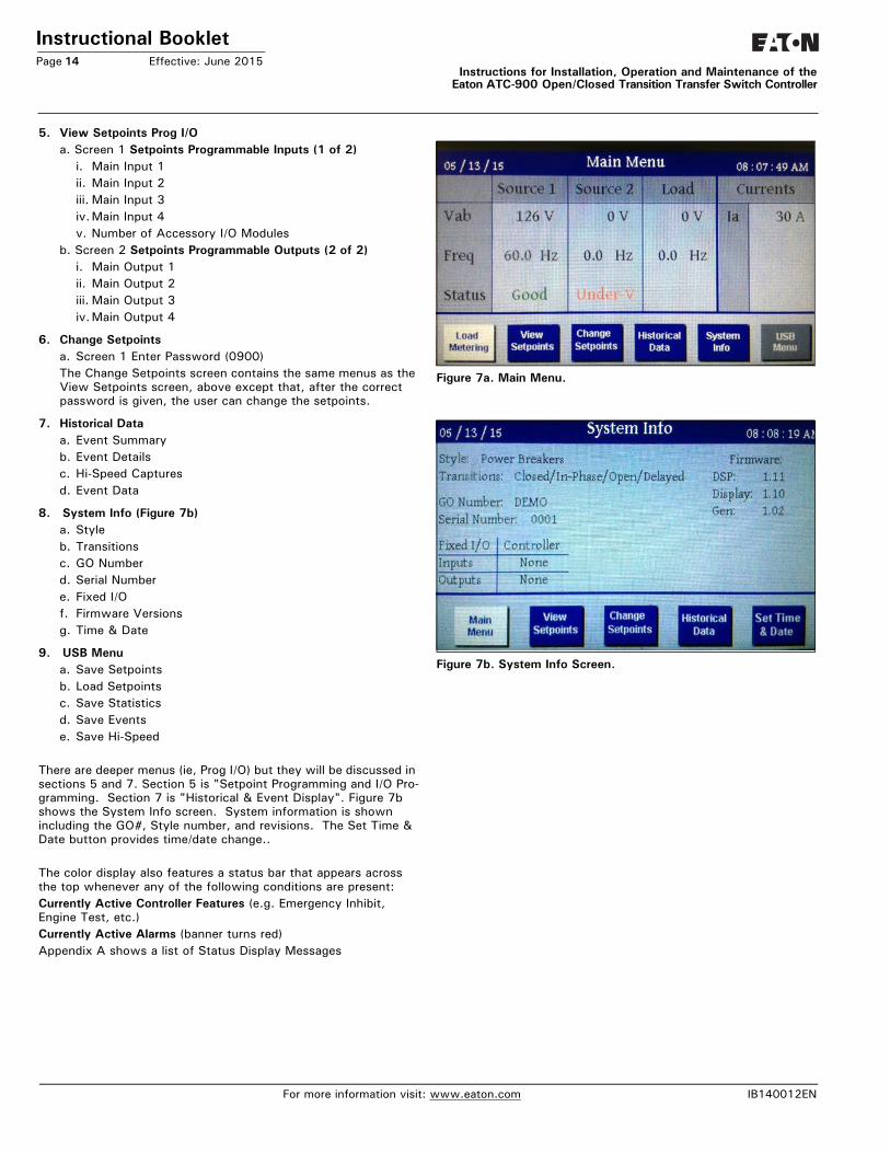
3.4.1 Color DisplayThe color display, under Main Menu contains six main top level functions. See Figure 7a. Remember, the display is not a touch screen; one must use the push buttons below the screen. This particular screen is showing 120 volts single phase and both of the sources are available.From these top level menus, one can navigate through the fea-tures. Section 5 shows how to program setpoints and I/Os. Sec-tion 7 shows how to view and download Historical Data and Events by using a thumb drive (memory stick). See Appendix A for Status Display Messages. Below is a map of the Display Menus.
Main Menu (Figure 7a)
Load Metering - View Setpoints - Change Setpoints - Historical Data - System Info - USB Menu
1. View Setpoints Systema. Screen 1 Setpoints - System Setup (1 of 3)
i. Language ii. Frequencyiii. System Voltageiv. Number of Phasesv. Generatorsvi. Preferred Sourcevii. PT Ratioviii.CT Ratioix. Automatic DSTx. Lead/Lag Signxi. CT Connection
b. Screen 2 Setpoints - System Setup (2 of 3)i. Operating Modeii. Phase Sequence Checkiii. Commit to Transferiv. Manual Retransferv. Modbus Addressvi. Modbus Configuration
c. Screen 2 Setpoints - System Setup (3 of 3)i. Closed Transition (No Sync to Alarm or Open)ii. Frequency Diffiii. Voltage Diffiv. In-Phase Transition (No Sync to Alarm or Open)v. Frequency Diffvi. Sync Timervii. Time Delay Neutral (TDN)viii.Load Decay
2. View Setpoints (Time Delays)i. TD Normal to Emergencyii. TD Emergency to Normaliii. TD Pre-Transferiv. TD Post Transferv. TD Engine Startvi. TD Engine Coolvii.TD Engine Fail
3. View Setpoints Dropouts/Pickupsa. Screen 1 Setpoints Voltage Limits (1 0f 3)
i. Undervoltage Dropoutii. Undervoltage Pickupiii. Overvoltage Dropoutiv.Overvoltage Pickup
b. Screen 2 Setpoints Frequency Limits (2 0f 3)i. Underfrequency Dropoutii. Underfrequency Pickupiii. Overfrequency Dropoutiv.Overfrequency Pickup
c. Screen 3 Setpoints Negative Sequence (3 0f 3)(Not available for single-phase systems)i. Voltage Unbalance Dropoutii. Voltage Unbalance Pickupiii. Voltage Phase Loss Dropoutiv. Voltage Phase Loss Pickupv. Current Unbalance Dropoutvi. Current Unbalance Pickupvii. Current Unbalance Enable Thresholdviii. Dropout Time Delayi.Voltage Unbalance Dropout
(Source 1 Source 2)
4. View Setpoints Engine Test/PEa. Screen 1 Setpoints - Engine Test/Plant Exercisers (1 of 3)
i. Engine Test Modeii. Engine Test Run Timeiii. TD Normal to Emergencyiv. TD Emergency to Normalv. TD Engine Cool
b. Screen 2 Setpoints - Plant Exerciser 1 (2 of 3)i. PE1 Test Modeii. PE1 Run Timeiii. Schedule iv. Start Timev. PE1 Dayvi. Exerciser 1 Dates
c. Screen 3 Setpoints - Plant Exerciser 2 (3 of 3)i. PE2 Test Modeii. PE2 Run Timeiii. Schedule iv. Start Timev. PE2 Dayvi. Exerciser 2 Dates
NOTICEWHETHER VIEWING OR PROGRAMMING, THE DISPLAY GOES TO THE HOME SCREEN IF NO PUSHBUTTON ACTIVITY IS DETECTED FOR APPROXIMATELY TWO MINUTES.
IB140012EN For more information visit: www.eaton.com
Instructional BookletPage 14 Effective: June 2015
Instructions for Installation, Operation and Maintenance of theEaton ATC-900 Open/Closed Transition Transfer Switch Controller
5. View Setpoints Prog I/Oa. Screen 1 Setpoints Programmable Inputs (1 of 2)
i. Main Input 1ii. Main Input 2iii. Main Input 3iv.Main Input 4v. Number of Accessory I/O Modules
b. Screen 2 Setpoints Programmable Outputs (2 of 2)i. Main Output 1ii. Main Output 2iii. Main Output 3iv.Main Output 4
6. Change Setpointsa. Screen 1 Enter Password (0900)The Change Setpoints screen contains the same menus as the View Setpoints screen, above except that, after the correct password is given, the user can change the setpoints.
7. Historical Dataa. Event Summaryb. Event Detailsc. Hi-Speed Capturesd. Event Data
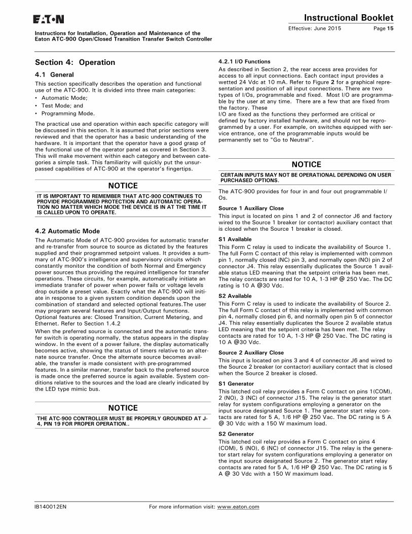
8. System Info (Figure 7b)a. Styleb. Transitionsc. GO Numberd. Serial Numbere. Fixed I/Of. Firmware Versionsg. Time & Date
9. USB Menua. Save Setpointsb. Load Setpointsc. Save Statisticsd. Save Eventse. Save Hi-Speed
There are deeper menus (ie, Prog I/O) but they will be discussed in sections 5 and 7. Section 5 is "Setpoint Programming and I/O Pro-gramming. Section 7 is "Historical & Event Display". Figure 7b shows the System Info screen. System information is shown including the GO#, Style number, and revisions. The Set Time & Date button provides time/date change..
The color display also features a status bar that appears across the top whenever any of the following conditions are present:Currently Active Controller Features (e.g. Emergency Inhibit, Engine Test, etc.)Currently Active Alarms (banner turns red)Appendix A shows a list of Status Display Messages
Figure 7a. Main Menu.
Figure 7. Main Menu.
Figure 7b. System Info Screen.
For more information visit: www.eaton.com IB140012EN
Instructional BookletEffective: June 2015 Page 15
Instructions for Installation, Operation and Maintenance of the Eaton ATC-900 Open/Closed Transition Transfer Switch Controller
Section 4: Operation4.1 GeneralThis section specifically describes the operation and functional use of the ATC-900. It is divided into three main categories:• Automatic Mode;• Test Mode; and• Programming Mode.
The practical use and operation within each specific category will be discussed in this section. It is assumed that prior sections were reviewed and that the operator has a basic understanding of the hardware. It is important that the operator have a good grasp of the functional use of the operator panel as covered in Section 3. This will make movement within each category and between cate-gories a simple task. This familiarity will quickly put the unsur-passed capabilities of ATC-900 at the operator’s fingertips.
4.2 Automatic ModeThe Automatic Mode of ATC-900 provides for automatic transfer and re-transfer from source to source as dictated by the features supplied and their programmed setpoint values. It provides a sum-mary of ATC-900’s intelligence and supervisory circuits which constantly monitor the condition of both Normal and Emergency power sources thus providing the required intelligence for transfer operations. These circuits, for example, automatically initiate an immediate transfer of power when power fails or voltage levels drop outside a preset value. Exactly what the ATC-900 will initi-ate in response to a given system condition depends upon the combination of standard and selected optional features.The user may program several features and Input/Output functions. Optional features are: Closed Transition, Current Metering, and Ethernet. Refer to Section 1.4.2When the preferred source is connected and the automatic trans-fer switch is operating normally, the status appears in the display window. In the event of a power failure, the display automatically becomes active, showing the status of timers relative to an alter-nate source transfer. Once the alternate source becomes avail-able, the transfer is made consistent with pre-programmed features. In a similar manner, transfer back to the preferred source is made once the preferred source is again available. System con-ditions relative to the sources and the load are clearly indicated by the LED type mimic bus.
4.2.1 I/O FunctionsAs described in Section 2, the rear access area provides for access to all input connections. Each contact input provides a wetted 24 Vdc at 10 mA. Refer to Figure 2 for a graphical repre-sentation and position of all input connections. There are two types of I/Os, programmable and fixed. Most I/O are programma-ble by the user at any time. There are a few that are fixed from the factory. These I/O are fixed as the functions they performed are critical or defined by factory installed hardware, and should not be repro-grammed by a user. For example, on switches equipped with ser-vice entrance, one of the programmable inputs would be permanently set to "Go to Neutral".
The ATC-900 provides for four in and four out programmable I/Os.
Source 1 Auxiliary CloseThis input is located on pins 1 and 2 of connector J6 and factory wired to the Source 1 breaker (or contactor) auxiliary contact that is closed when the Source 1 breaker is closed.
S1 AvailableThis Form C relay is used to indicate the availability of Source 1. The full Form C contact of this relay is implemented with common pin 1, normally closed (NC) pin 3, and normally open (NO) pin 2 of connector J4. This relay essentially duplicates the Source 1 avail-able status LED meaning that the setpoint criteria has been met. The relay contacts are rated for 10 A, 1-3 HP @ 250 Vac. The DC rating is 10 A @30 Vdc.
S2 AvailableThis Form C relay is used to indicate the availability of Source 2. The full Form C contact of this relay is implemented with common pin 4, normally closed pin 6, and normally open pin 5 of connector J4. This relay essentially duplicates the Source 2 available status LED meaning that the setpoint criteria has been met. The relay contacts are rated for 10 A, 1-3 HP @ 250 Vac. The DC rating is 10 A @30 Vdc.
Source 2 Auxiliary CloseThis input is located on pins 3 and 4 of connector J6 and wired to the Source 2 breaker (or contactor) auxiliary contact that is closed when the Source 2 breaker is closed.
S1 GeneratorThis latched coil relay provides a Form C contact on pins 1(COM), 2 (NO), 3 (NC) of connector J15. The relay is the generator start relay for system configurations employing a generator on the input source designated Source 1. The generator start relay con-tacts are rated for 5 A, 1/6 HP @ 250 Vac. The DC rating is 5 A @ 30 Vdc with a 150 W maximum load.
S2 GeneratorThis latched coil relay provides a Form C contact on pins 4 (COM), 5 (NO), 6 (NC) of connector J15. The relay is the genera-tor start relay for system configurations employing a generator on the input source designated Source 2. The generator start relay contacts are rated for 5 A, 1/6 HP @ 250 Vac. The DC rating is 5 A @ 30 Vdc with a 150 W maximum load.
NOTICEIT IS IMPORTANT TO REMEMBER THAT ATC-900 CONTINUES TO PROVIDE PROGRAMMED PROTECTION AND AUTOMATIC OPERA-TION NO MATTER WHICH MODE THE DEVICE IS IN AT THE TIME IT IS CALLED UPON TO OPERATE.
NOTICETHE ATC-900 CONTROLLER MUST BE PROPERLY GROUNDED AT J-4, PIN 19 FOR PROPER OPERATION..
NOTICECERTAIN INPUTS MAY NOT BE OPERATIONAL DEPENDING ON USER PURCHASED OPTIONS.
IB140012EN For more information visit: www.eaton.com
Instructional BookletPage 16 Effective: June 2015
Instructions for Installation, Operation and Maintenance of theEaton ATC-900 Open/Closed Transition Transfer Switch Controller
Transfer Operation Connections Output Relays K1, K2, K3, K4K1, K2, K3, and K4 on J6 pins 5 through 12 are factory wired to operate the transfer switch. The relay contacts for each are rated for 10 A, 1/3 HP @ 250 Vac. The DC rating is 10 A @30 Vdc.The K relay outputs are used to control the transfer device. Cer-tain configurations of power use only the Open K relays. The K relays default configuration is:
K1 = S2 Open (Trip)K2 = S1 Open (Trip)K3 = S1 CloseK4 = S2 Close
The user should refer to the switch drawings for usage. The relays mementarily energize until the ATC-900 senses that the switching device has closed or opened (Using AUX-illary contacts) and then de-energizes the K relay to the normally open state.
4.2.2 Popular Inputs and Outputs (Programmable I/O)The following are some popular I/Os that can be programmed. See the I/O Table 5 in Section 5.5 and Appendix B for all of the I/O Descriptions. A configurable (programmable) input can only be defined to one contact while an output can have multiple con-tacts. A fixed input or output is one that is not user programma-ble as it is fixed from the factory. It is tied to a switch or function of a switch that requires that input or output.
Lockout (Input)The Lockout contact is closed to enable normal, automatic opera-tion. Opening this contact will Inhibit all automatic operation. This feature is used when non-automatic control is required. The ATC-900 continues to monitor source status and will accurately display status on the controller's mimic bus. After the controller has been locked, the user must reset the controller by simultane-ously pressing the Help and Enter buttons.
Go To Emergency (Input)When the Go to Emergency contact is closed, a transfer to the Emergency Source will be initiated. If the Emergency Source fails and the Normal Source is available, the ATC-900 will initiate a transfer back to the Normal Source (failsafe).The Go To Emergency input is only usable when either Source 1 or Source 2 is preferred. This input will be disabled when the Pre-ferred Source selection is set to None.The Emergency Inhibit input takes priority over the Go To Emer-gency input if both are activated at the same time. In this case, the generator will start but a transfer to the Emergency Source will be inhibited until the Emergency Inhibit input is de-activated.
Bypass Timers (Input)This momentary contact will bypass the timer for TDEN, TDNE, TDN, TDES, and TDEC. By pushing the Help and Enter buttons on the front of the controller (Bypass Timer) at the same time the countdown will be set to 0 for the current countdown. The next timer will then start. There is also a programmable input that will allow the bypass timer to be completed remotely if desired.
Go To Neutral (Input)A maintained closed contact forces the controller to switch to the Neutral position, thereby disconnecting the load from both sources.
Manual Re-Transfer (Input)With manual retransfer enabled, a momentary closure allows the ATC-900 to proceed with a re-transfer operation at the operators discretion. Should a failure of the emergency source occur while waiting for the manual return, the re-transfer proceeds automati-cally (failsafe).
Emergency Inhibit (Load Shed) (Input)This input is enabled when the Emergency Inhibit (36) is enabled. The contact is closed for normal operation. Opening this contact will activate the Emergency Inhibit input.If the Emergency Inhibit contact is opened when the load is con-nected to the Normal Source, no action will be taken if the Normal Source is available. If the Normal Source is not available, an imme-diate transfer to the Neutral position will occur.If the Emergency Inhibit contact is opened when the load is con-nected to the Emergency Source, the ATC-900 will transfer the load to the Normal Source if it is available. If the Normal Source is not available, an immediate transfer to the Neutral position will occur if the Emergency Source is available.The Emergency Inhibit input is only active when either Source 1 or Source 2 is preferred. This input is ignored if the Preferred Source selection is set to None.The Emergency Inhibit input takes priority over the Go To Emer-gency input if both inputs are activated at the same time. In this case, the generator will start but a transfer to the Emergency Source will be inhibited until the Emergency Inhibit input is de-acti-vated. If the preferred source is lost during this time, the switch will transfer to the Neutral position.
Three Source ATS Control (Master (output)/Slave (Input))The ATC-900 Master/Slave controller functionality provides the user with the ability to control a three-source system consisting of a utility and two generator sources. In a three-source system, the Master ATS controls the engine starting and stopping of the Slave ATS. See Feature list, 90A and 90B for a full functionality write-up.Note: The Slave ATS requires the DCT module for a DC power inputto keep the controller powered or a UPS if desired.
The Master ATS handles all transfer time delays between the Util-ity to Generator transfer. The master is the Generator Start from the first ATS.
4.4 Test Mode
The Engine Test is intended to allow periodic system tests. The exact test conditions are determined by the programmed set-points. The operator-selected parameters include setting the engine run time and the Test Mode. Refer to Table 4 for test pro-gramming details.
There are three test modes:1 No Load Engine Run Test;2 Load Transfer Engine Test; or3 Disabled.
IF THE ATS IS UNABLE TO PROCESS A ENGINE TEST REQUEST DUE TO THE ATS STATUS, THE REQUEST IS IGNORED.
When the Engine Test pushbutton is pressed, the display will prompt the user to input a password (factory set to 0900). Use the arrow keys to enter the password, then press the right arrow key to highlight the "Enter Password" icon and press the Enter key.
The ATC-900 will display the Time Delay on Engine Starting (TDES) timer countdown. Once the TDES countdown reaches zero, the ATC-900 Controller will initiate an engine start. The engine run duration will be per the Engine Run Test Time setpoint.
For more information visit: www.eaton.com IB140012EN

Instructional BookletEffective: June 2015 Page 17
Instructions for Installation, Operation and Maintenance of the Eaton ATC-900 Open/Closed Transition Transfer Switch Controller
If Test Mode is set to "Engine Run", then the switch will start the non-preferred generator, but will not initiate a transfer to the non-preferred source.
If Test Mode is set to "Load Transfer", then the switch will start the non-preferred generator and initiate a transfer to the non-pre-ferred source once the generator output has reached the specified setpoints.
All enabled and programmed time delays will be performed per the setpoints during an engine test. The time delays will appear on the LCD Display with “countdown to zero” when active. Depending on the setpoints and the optional features selected with the ATC-900 Controller, these can include:
• Time Delay Engine Start (TDES);• Time Delay Normal to Emergency (TDNE);• Time Delay Emergency to Normal (TDEN);• Time Delay for Engine Cooldown (TDEC);• Time Delay Neutral (TDN); and• Pre-transfer Delay Signal (TD PRE-TRAN).• Post-transfer Delay Signal (TD POST-TRAN).
All operations are “Failsafe”, meaning they prevent disconnection from the only available power source and also force a transfer or re-transfer operation to the only available power source.
During an engine test, if the Engine Test pushbutton is pressed a second time before the Engine Test is complete, the Engine Test will be terminated. An engine test may also be aborted in the fol-lowing ways:1. If the Emergency Source does not become available within 90
seconds of the ATC-900 providing the engine start command;
2. If, during the TDNE countdown, the Emergency Source goes unavailable more than three times (Each time, TDNE will restart);
3. If the Emergency Source is powering the load and it goes unavailable for more than the TDEF (Time Delay Engine Fail-ure) setting; and
4. If the Normal source becomes unavailable.
When an engine test is aborted due to an unavailable source dur-ing TDNE countdown, the Alarm relay will energize, a “TEST ABORTED” message with appear on the display, and the event will be logged into the Transfer History as “Aborted Test” Aborted.
4.5 USB Interface (Event Status-Setpoints)Every ATC-900 transfer switch includes a front panel, NEMA 4X rated USB port for use in configuring set points or downloading event data to a USB flash drive. The USB interface is brought to the front of the enclosure to enable flash memory (memory stick) to be plugged in to upload or download data such as History Data Logging, or Setpoints. The USB interface will only work with memory devices and not laptop computers.
4.5.1 Upload/Download Setpoints via USBTo reduce the time spent on site for commissioning, set points can be configured at a PC using the ATC-900 configuration software and saved to a USB flash drive to be uploaded to one or multiple controllers. Set points are also easily copied from one controller to another.
4.5.2 Downloading Statistics and Event logs via USBDownloading statistics and event capture data provides the user the ability to more thoroughly analyze high speed capture data using a PC, or data can be emailed to Eaton's Technical Support Team when off site troubleshooting support is required. Section 7.1 shows the instructions for downloading event capture data.
4.6 CommunicationsATC-900 is a Monitoring Protection and Control Communications compatible device. As such, it can be remotely monitored, con-trolled, and setpoint programmed. The ATC-900 is supplied equipped with a Modbus RTU (RS-485 physical layer) communica-tions port as standard. This permits it to have the communications option supplied from the factory. A COTS (Commercial Off The Shelf) Ethernet to Modbus can also be used.
4.6.1 Power Distribution SoftwareThe ATC-900 is also compatible with Eaton’s Power Xpert Gate-way for web-based monitoring, via Modbus TCP/IP, SNMP, or BACnetT/IP Protocols. The Power Xpert Gateway can be used to consolidate data from up to 64 devices, including communications ready transfer switch controllers, trip units, and meters, as well as other Eaton devices. Certain Versions of the Power Xpert Gate-way include email event notification and data-logging functional-ity. Additional features include:• System/device alarm logging and reporting;• Time/event historical data logging;• Data trending;• Information storage/retrieval by device event;• Hardware diagnostics;• Dedicated computer not required;• Security password protection; and• Gateway interface for connectivity to other information net-
works.
IB140012EN For more information visit: www.eaton.com
Instructional BookletPage 18 Effective: June 2015
Instructions for Installation, Operation and Maintenance of theEaton ATC-900 Open/Closed Transition Transfer Switch Controller
Section 5: Setpoint Programming and I/O Programming Using the Color Display5.1 Introduction
The ATC-900 is fully programmable from the device’s faceplate or through the communications port. Users can reprogram setpoints as well as other parameters. Up to four optional I/O modules, each having four in and four out programmble I/Os can be used with the ATC-900. That is a total of 20 Input and Outputs that can be user programmed. Some inputs will require controller setpoints to be set to a certain configuration. See Section 5.6 for some rules and more information.
5.2 Entering and Exiting the Program Mode
Using the left/right arrow keys, navigate to the desired screen icon and press the Enter key. The "Change Setpoints" screen will require a password to access (factory default is 0900).
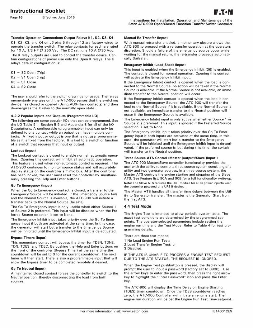
1. Load MeteringThe Load Metering screen presents (Figure 8) the different mea-surements of the Load. Note that the DCT module is required to display Load current, Watts, VAR, VA, and power factor. Other-wise only voltage measurements will be shown. See Section 2 for the DCT Module specifications.
Figure 8. Load Metering.
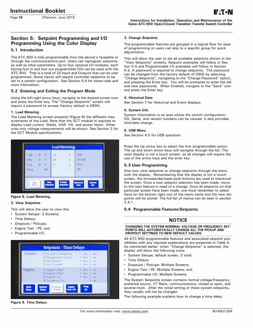
2. View Setpoints
This will allow the user to view the:• System Setups: 3 Screens;• Time Delays;• Dropouts / Pickups;• Engine Test / PE; and• Programmable I/O.
Figure 9. Time Delays.
3. Change Setpoints
The programmable features are grouped in a logical flow for ease of programming or users can skip to a specific group for quick adjustments.
This will allow the user to set all available setpoints shown in the "View Setpoints" screens. Setpoint examples will follow in Sec-tion 5.4 and Programmable I/O examples will follow in Section 5.5. A password is required to change setpoints. The password can be changed from the factory default of 0900 by selecting "Change Setpoints", navigating to the "Change Password" option, and pressing the Enter key. You will be prompted to enter the old and new passwords. When finished, navigate to the "Save" icon and press the Enter key.
4. Historical DataSee Section 7 for Historical and Event displays.
5. System InfoSystem Information is an area where the switch configuration, GO, Serial, and version numbers can be viewed. It also provides time/date change.
6. USB MenuSee Section 4.5 for USB operation.
Press the Up arrow key to select the first programmable option. The up and down arrow keys will navigate through the list. The color display is not a touch screen, so all changes will require the use of the arrow keys and the enter key.
5.3 User ProgrammingOne may view setpoints or change setpoints through the menu with the display. Remembering that the display is not a touch-screen, the increase/decrease push buttons are used to maneuver the screen. Once a new setpoint selection has been made, move to the next feature in need of a change. Once all setpoints on that particular screen have been made, one must remember to select Save on the bottom right row of the menu items and the new set-points will be stored. The full list of menus can be seen in section 3.4.1
5.4 Programmable Features/Setpoints
All ATC-900 programmable features and associated setpoint pos-sibilities with any required explanations are presented in Table 4. As mentioned earlier, when "Change Setpoints" is selected, the display will show the following icons:• System Setups: default screen, 3 total;• Time Delays;• Dropouts / Pickups: Multiple Screens;• Engine Test / PE: Multiple Screens; and• Programmable I/O: Multiple Screens.
The System Setpoints screen contains normal voltage/frequency, preferred source, CT Ratio, communications, closed or open, and several more. After the initial setting of these system setpoints, they usually will not be changed.The following example explains how to change a time delay.
NOTICECHANGING THE SYSTEM NOMINAL VOLTAGE OR FREQUENCY SET-POINTS WILL AUTOMATICALLY CHANGE ALL THE PICKUP AND DROPOUT SETTINGS TO NEW DEFAULT VALUES.
For more information visit: www.eaton.com IB140012EN
Instructional BookletEffective: June 2015 Page 19
Instructions for Installation, Operation and Maintenance of the Eaton ATC-900 Open/Closed Transition Transfer Switch Controller
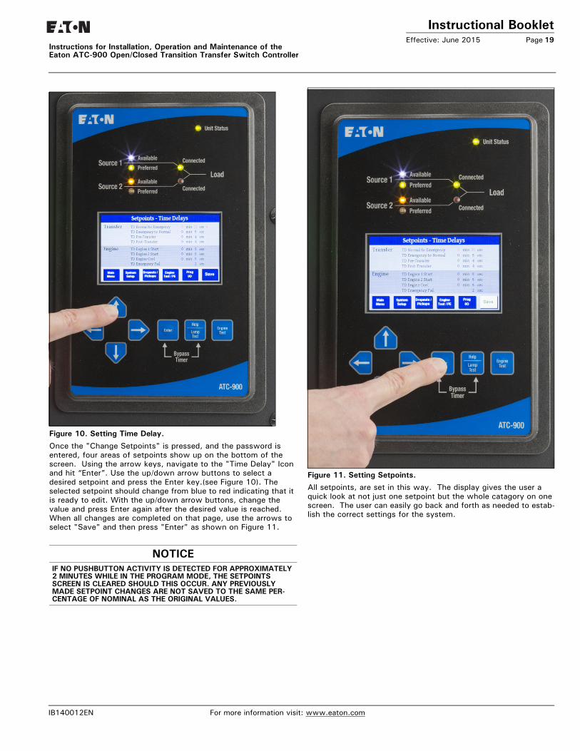
Figure 10. Setting Time Delay.
Once the "Change Setpoints" is pressed, and the password is entered, four areas of setpoints show up on the bottom of the screen. Using the arrow keys, navigate to the "Time Delay" Icon and hit “Enter”. Use the up/down arrow buttons to select a desired setpoint and press the Enter key.(see Figure 10). The selected setpoint should change from blue to red indicating that it is ready to edit. With the up/down arrow buttons, change the value and press Enter again after the desired value is reached. When all changes are completed on that page, use the arrows to select "Save" and then press "Enter" as shown on Figure 11.
Figure 11. Setting Setpoints.All setpoints, are set in this way. The display gives the user a quick look at not just one setpoint but the whole catagory on one screen. The user can easily go back and forth as needed to estab-lish the correct settings for the system.
NOTICEIF NO PUSHBUTTON ACTIVITY IS DETECTED FOR APPROXIMATELY 2 MINUTES WHILE IN THE PROGRAM MODE, THE SETPOINTS SCREEN IS CLEARED SHOULD THIS OCCUR. ANY PREVIOUSLY MADE SETPOINT CHANGES ARE NOT SAVED TO THE SAME PER-CENTAGE OF NOMINAL AS THE ORIGINAL VALUES.
IB140012EN For more information visit: www.eaton.com

Instructional BookletPage 20 Effective: June 2015
Instructions for Installation, Operation and Maintenance of theEaton ATC-900 Open/Closed Transition Transfer Switch Controller
Table 4. Programmable Features/Setpoints.
Table 4 is continued in column 2 of this page.
OPTIONNUMBER DESCRIPTION RANGE
FACTORY DEFAULT
General settings
— Set new password 0000–9999 0900
— Selected language English, French or Spanish English
— Nominal frequency 50 or 60 Hz As ordered
— Nominal voltage 110–600V As ordered
— Number of phases 1 or 3 As ordered
— Number of generators 0, 1 or 2 1
— Preferred source Source 1, Source 2, External*or None
Source 1
— PT ratio 2:1–500:1 As ordered
— CT ratio 200–5000 —
— Daylight Saving Time On or Off 1
— Operating mode Stand-alone/Master or Slave* Master
— Phase sequence check ABC, CBA or Off Off
— Commitment to transfer in TDNE Yes or No No
— Manual retransfer Auto, Manual* or External * Auto
— Modbus address 1–247 1
— Modbus baud rate 0 = 9600, 1, Even 0
1 = 9600, 1, Odd —
2 = 9600, 2, None —
3 = 9600, 1, None —
4 = 19,200, 1, Even —
5 = 19,200, 1, Odd —
6 = 19,200, 2, None —
7 = 19,200, 1, None —
Transition settings
47 Closed transition
Closed transition Disabled, On to Alarm, On to Open As ordered
Closed voltage difference 1–5% 2%
Closed frequency difference 0.0–0.3 Hz 0.3
32f/32d Open—in-phase transition
In-phase Disabled, On to Alarm, On to Open As ordered
In-phase frequency difference 0.0–3.0 Hz 1.0
— Synchronization timer 1–60 minutes 5
32a/32d Open—delayed transition
Time delay neutral 10 Minutes 0
Load voltage decay 2–30% of nominal voltage 6%
Time delays
1a Time delay normal to emergency 0–9999 seconds 0:00
3a Time delay emergency to normal 0–9999 seconds 5:00
35A Time delay pre-transfer 0–120 seconds 0:01
35C Time delay post-transfer 0–120 seconds 0:10
2A Time delay engine 1 start 259 Minutes ** 0:03
— Time delay engine 2 start 259 Minutes ** 0:03
4A Time delay engine cool-off 0–9999 seconds 5:00
7A Time delay engine fail timer 0–6 seconds 0:06
— Unbalance/phase loss time delay 10–30 seconds 0:20
* Requires the associated programmable input to be configured/connected.** Any TDES value above two minutes, with no power on the controller, will start the genera-
tor (fail-safe) after two minutes.
0:00:00 is Hours : Minutes : Seconds
Source settings (Both sources have the same ranges and defaults)
26/5P
Source 1/2 undervoltage dropout 70–97% of nominal 80%
Source 1/2 undervoltage pickup (dropout + 2%) to 99% of nominal
90%
26/5K
Source 1/2 overvoltage dropout 105–120% of nominal (0 = disabled)
115%
Source 1/2 overvoltage pickup 103% of nominal to (dropout - 2%) (0 = disabled)
110%
26/5J Source 1/2 underfrequency dropout 90–97% of nominal (0 = disabled)
94%
96%Source 1/2 nderfrequency pickup (dropout + 1 Hz) to 99% of nominal (0 = disabled)
26/5N Source 1/2 overfrequency dropout 103–110% (0 = disabled) 106%
104%Source 1/2 overfrequency pickup 101% to (dropout - 1 Hz) (0 = disabled)
26/5L Source 1/2 percent for unbalanced voltage dropout
5–20% neg./pos. sequence voltage V2/V1 (0 = disabled)
12%
Source 1/2 percent for unbalanced voltage pickup
3% to (dropout - 2%) (0 = disabled)
10%
26/5M Source 1/2 voltage phase loss drop-out
20-60% V2/V1 (0 = disabled) 40%
Source 1/2 voltage phase loss pickup 18% to (dropout - 2%) (0 = dis-abled)
30%
- Load current unbalance dropout 5-60% neg./pos. sequence current I2/I1 (0 = disabled)
12%
- Load current unbalance pickup 3% to (dropout - 2%) (0 = disabled) 10%
- Load current unbalance enable threshold
1-100% of rated current 10%
Engine test/plant exerciser (PE1 and PE2 are independently programmable)
6B Engine test pushbutton on panel Load transfer 30 minutes
Test mode No load, load transfer, disabled
Engine run test time 0–600 minutes
23M PE time delay normal to emergency 0–9999 seconds 00:02
PE time delay emergency to normal 0–9999 seconds 00:02
PE time delay engine cooldown 0–9999 seconds 5 minutes
PE1/PE2 test mode No load, load transfer, disabled Disabled
PE1/PE2 run time 0–600 minutes 30 minutes
PE1/PE2 schedule Off, daily, 7-day, 14-day, 28-day or calendar date (up to 12 user-speci-fied dates)
PE1/PE2 calendar date Month: 1–12; Day: 1–31
PE1/PE2 day of week 1 Sunday, 2 Monday, 3 Tuesday, 4 Wednesday, 5 Thursday, 6 Friday or 7 Saturday
PE1/PE2 plant start time HH:MM AM/PM
For more information visit: www.eaton.com IB140012EN

Instructional BookletEffective: June 2015 Page 21
Instructions for Installation, Operation and Maintenance of the Eaton ATC-900 Open/Closed Transition Transfer Switch Controller
5.5 Programming I/OsThe ATC-900 has four inputs and four outputs that are program-mable I/Os. The outputs are Form C types and easily assessable. Depending on the switch types, the I/Os are wired out to the ter-minal blocks that are easily assessable. If they are not wired out to terminal blocks, the controller will contain the necessary plugs to tap into easily. The terminal blocks also have engine start (Gen Start) and S1/S2 availability wired. If more I/Os are required, the use of an I/O module is required as shown in Section 2.5.2. Up to four I/O modules can be used which will give 20 programmable I/O. In most cases, the controller itself or the controller with one I/O module should be enough. The I/O module can also be added on in the field if the application calls out for more I/Os. The following are the programmable Inputs and Outputs of the controller. See Appendix B for a description of the available I/Os.
Programmable Inputs• Remote Engine Test• Bypass Timers• Preferred Source Selector • Go to Emergency (S2) • ATS on Bypass• Manual Retransfer• Enable Manual Retransfer• Load Shed - S2 Inhibit• Go to Neutral Position (not SE Rated)• Lockout• Monitor Mode (NC or NO)• Slave Input • Disable (Default settings)
Programmable Outputs (Form C)• Normal (S1) Source Available• Emergency (S2) Source Available• Normal (S1) Source Position• Emergency (S2) Source Position• Pretransfer Signal Contacts 1• Post Transfer Signal Contacts 1• Pre/Post Transfer Signal• Load Sequencing Contacts (1)• Load Sequencing Contacts (2)• Load Sequencing Contacts (3)• Load Sequencing Contacts (4) • Load Sequencing Contacts (5)• Load Sequencing Contacts (6)• Load Sequencing Contacts (7)• Load Sequencing Contacts (8) • Load Sequencing Contacts (9)• Load Sequencing Contacts (10)• Selective Load Shed • General Alarm Indication Contact• ATS Not in Automatic• ATS in Test• Engine Test Aborted• Cooldown in Process• Engine Start Contact Status (Gen 1 & 2)• LOAD SHED - Emergency Inhibit On• ATS on Bypass• Load Bank Control
• Remote I/O (Controllable by Modbus)• Health• Disable (Default Settings)* See descirptions of each I/O in Appendix B
Note: S2 Permit (Input), S2 Request (Output), and TDNF (Timer) are used on a private switch, please see switch instruction booklet for information
Outputs (Alarms & Warnings)Appendix A: Feature List and Status Display Messages (page 39) in the status area at the end of the manual describes the Yellow and Red banners on the ATC-900. Any flashing red banners will energize the programmable output general alarm indication con-tact.
Each I/O module uses a CAT V straight cable or better, and are strung together to the ATC-900's J11 connector.Table 5 shows most of the ATC-900's features and the program-mability of each. There are five categories:• P Programmable • PF Programmable Fixed I/O• O Optional• OF Optional Fixed• S StandardIn some applications, a certain I/O will be fixed (PF) from the fac-tory and the user will not be able to change the location of the I/O. An example of this is for Service Entrance. Service Entrance requires the “Go to Neutral” (option 37) input. This is a function of the switch so the user will not be able to change which input "Go to Neutral" is set to on the ATC-900. For the Optional Fixed, an example would be for a Preferred Source Selector (10C), which is an external two position switch that allows the user to select the preferred source. Anything with an external switch on the door will require that particular I/O to be fixed. When any of the I/O is fixed, the color will be black (instead of Blue) and it will also show up in the System Info Menu screen.There are some options that will require an I/O module due to a large number of fixed I/O required. There could be several I/Os that are associated with an option i.e. Load Sequencing Contacts. Some programmed input examples are shown below. These can be easily change by the user.
#1 Input Lockout 81J#2 Input Go to Neutral (Isolated) 37#3 Input S2 Inhibit (Load Shed) 36#4 Input Go to S2 26D
IB140012EN For more information visit: www.eaton.com
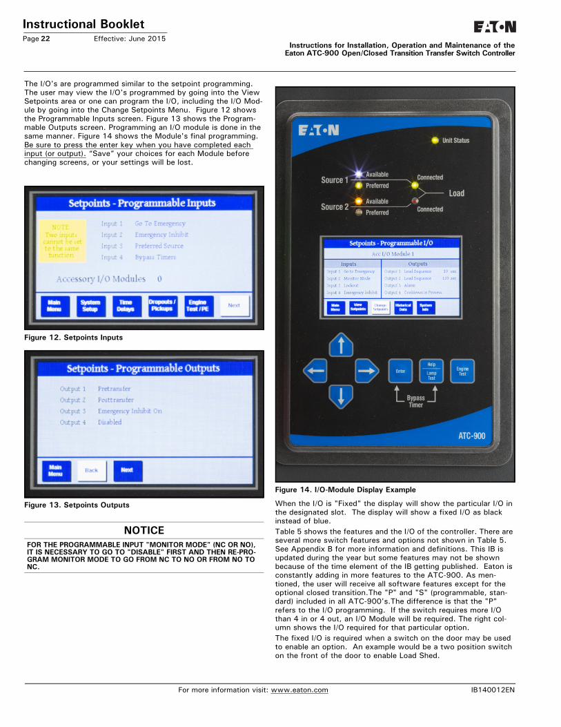
Instructional BookletPage 22 Effective: June 2015
Instructions for Installation, Operation and Maintenance of theEaton ATC-900 Open/Closed Transition Transfer Switch Controller
The I/O's are programmed similar to the setpoint programming. The user may view the I/O's programmed by going into the View Setpoints area or one can program the I/O, including the I/O Mod-ule by going into the Change Setpoints Menu. Figure 12 shows the Programmable Inputs screen. Figure 13 shows the Program-mable Outputs screen. Programming an I/O module is done in the same manner. Figure 14 shows the Module's final programming. Be sure to press the enter key when you have completed each input (or output). “Save” your choices for each Module before changing screens, or your settings will be lost.
Figure 12. Setpoints Inputs
Figure 13. Setpoints Outputs
Figure 14. I/O-Module Display Example
When the I/O is "Fixed" the display will show the particular I/O in the designated slot. The display will show a fixed I/O as black instead of blue.Table 5 shows the features and the I/O of the controller. There are several more switch features and options not shown in Table 5. See Appendix B for more information and definitions. This IB is updated during the year but some features may not be shown because of the time element of the IB getting published. Eaton is constantly adding in more features to the ATC-900. As men-tioned, the user will receive all software features except for the optional closed transition.The "P" and "S" (programmable, stan-dard) included in all ATC-900's.The difference is that the "P" refers to the I/O programming. If the switch requires more I/O than 4 in or 4 out, an I/O Module will be required. The right col-umn shows the I/O required for that particular option. The fixed I/O is required when a switch on the door may be used to enable an option. An example would be a two position switch on the front of the door to enable Load Shed.
NOTICEFOR THE PROGRAMMABLE INPUT "MONITOR MODE" (NC OR NO), IT IS NECESSARY TO GO TO "DISABLE" FIRST AND THEN RE-PRO-GRAM MONITOR MODE TO GO FROM NC TO NO OR FROM NO TO NC.
For more information visit: www.eaton.com IB140012EN
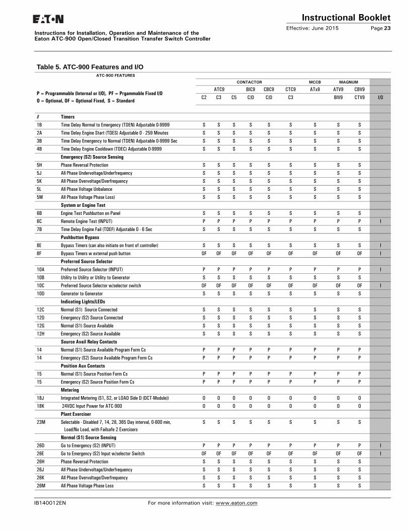
Instructional BookletEffective: June 2015 Page 23
Instructions for Installation, Operation and Maintenance of the Eaton ATC-900 Open/Closed Transition Transfer Switch Controller
Table 5. ATC-900 Features and I/O (Cont.).ATC-900 FEATURES
P = Programmable (Internal or I/O), PF = Prgammable Fixed I/OO = Optional, OF = Optional Fixed, S = Standard
CONTACTOR MCCB MAGNUM
ATC9 BIC9 CBC9 CTC9 ATx9 ATV9 CBV9
C2 C3 C5 C/D C/D C3 BIV9 CTV9 I/O
# Timers
1B Time Delay Normal to Emergency (TDEN) Adjustable 0-9999 S S S S S S S S S
2A Time Delay Engine Start (TDES) Adjustable 0 - 259 Minutes S S S S S S S S S
3B Time Delay Emergency to Normal (TDEN) Adjustable 0-9999 Sec S S S S S S S S S
4B Time Delay Engine Cooldown (TDEC) Adjustable 0-9999 S S S S S S S S S
Emergency (S2) Source Sensing
5H Phase Reversal Protection S S S S S S S S S
5J All Phase Undervoltage/Underfrequency S S S S S S S S S
5K All Phase Overvoltage/Overfrequency S S S S S S S S S
5L All Phase Voltage Unbalance S S S S S S S S S
5M All Phase Voltage Phase Loss) S S S S S S S S S
System or Engine Test
6B Engine Test Pushbutton on Panel S S S S S S S S S
6C Remote Engine Test (INPUT) P P P P P P P P P I
7B Time Delay Engine Fail (TDEF) Adjustable 0 - 6 Sec S S S S S S S S S
Pushbutton Bypass
8E Bypass Timers (can also initiate on front of controller) S S S S S S S S S I
8F Bypass Timers w external push button OF OF OF OF OF OF OF OF OF I
Preferred Source Selector
10A Preferred Source Selector (INPUT) P P P P P P P P P I
10B Utility to Utility or Utility to Generator S S S S S S S S S
10C Preferred Source Selector w/selector switch OF OF OF OF OF OF OF OF OF I
10D Generator to Generator S S S S S S S S S
Indicating Lights/LEDs
12C Normal (S1) Source Connected S S S S S S S S S
12D Emergency (S2) Source Connected S S S S S S S S S
12G Normal (S1) Source Available S S S S S S S S S
12H Emergency (S2) Source Available S S S S S S S S S
Source Avail Relay Contacts
14 Normal (S1) Source Available Program Form Cs P P P P P P P P P
14 Emergency (S2) Source Available Program Form Cs P P P P P P P P P
Position Aux Contacts
15 Normal (S1) Source Position Form Cs P P P P P P P P P
15 Emergency (S2) Source Position Form Cs P P P P P P P P P
Metering
18J Integrated Metering (S1, S2, or LOAD Side D (DCT-Module)) O O O O O O O O O
18K 24VDC Input Power for ATC-900 O O O O O O O O O
Plant Exerciser
23M Selectable - Disabled 7, 14, 28, 365 Day interval, 0-600 min, Load/No Load, with Failsafe 2 Exercisers
S S S S S S S S S
Normal (S1) Source Sensing
26D Go to Emergency (S2) (INPUT) P P P P P P P P P I
26E Go to Emergency (S2) Input w/selector Switch OF OF OF OF OF OF OF OF OF I
26H Phase Reversal Protection S S S S S S S S S
26J All Phase Undervoltage/Underfrequency S S S S S S S S S
26K All Phase Overvoltage/Overfrequency S S S S S S S S S
26M All Phase Voltage Phase Loss S S S S S S S S S
IB140012EN For more information visit: www.eaton.com
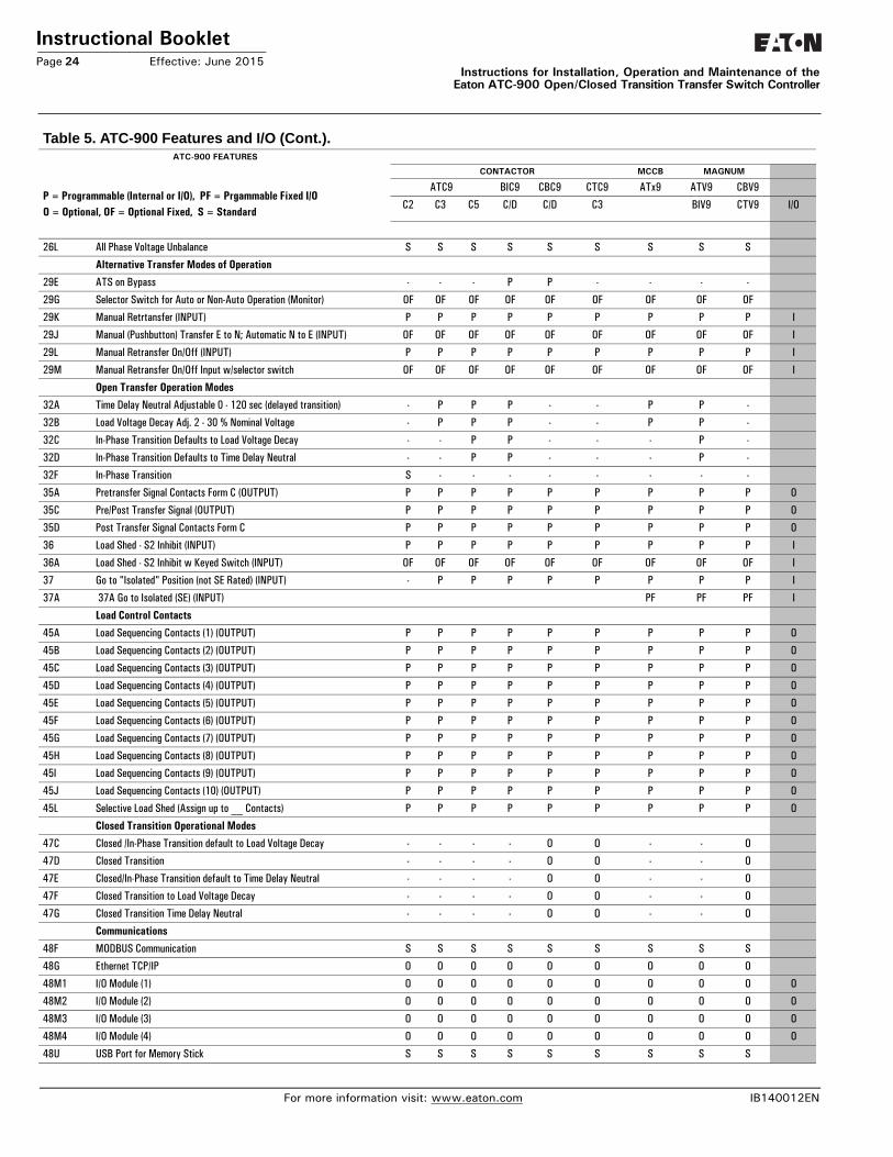
Instructional BookletPage 24 Effective: June 2015
Instructions for Installation, Operation and Maintenance of theEaton ATC-900 Open/Closed Transition Transfer Switch Controller
26L All Phase Voltage Unbalance S S S S S S S S S
Alternative Transfer Modes of Operation
29E ATS on Bypass - - - P P - - - -
29G Selector Switch for Auto or Non-Auto Operation (Monitor) OF OF OF OF OF OF OF OF OF
29K Manual Retrtansfer (INPUT) P P P P P P P P P I
29J Manual (Pushbutton) Transfer E to N; Automatic N to E (INPUT) OF OF OF OF OF OF OF OF OF I
29L Manual Retransfer On/Off (INPUT) P P P P P P P P P I
29M Manual Retransfer On/Off Input w/selector switch OF OF OF OF OF OF OF OF OF I
Open Transfer Operation Modes
32A Time Delay Neutral Adjustable 0 - 120 sec (delayed transition) - P P P - - P P -
32B Load Voltage Decay Adj. 2 - 30 % Nominal Voltage - P P P - - P P -
32C In-Phase Transition Defaults to Load Voltage Decay - - P P - - - P -
32D In-Phase Transition Defaults to Time Delay Neutral - - P P - - - P -
32F In-Phase Transition S - - - - - - - -
35A Pretransfer Signal Contacts Form C (OUTPUT) P P P P P P P P P O
35C Pre/Post Transfer Signal (OUTPUT) P P P P P P P P P O
35D Post Transfer Signal Contacts Form C P P P P P P P P P O
36 Load Shed - S2 Inhibit (INPUT) P P P P P P P P P I
36A Load Shed - S2 Inhibit w Keyed Switch (INPUT) OF OF OF OF OF OF OF OF OF I
37 Go to "Isolated" Position (not SE Rated) (INPUT) - P P P P P P P P I
37A 37A Go to Isolated (SE) (INPUT) PF PF PF I
Load Control Contacts
45A Load Sequencing Contacts (1) (OUTPUT) P P P P P P P P P O
45B Load Sequencing Contacts (2) (OUTPUT) P P P P P P P P P O
45C Load Sequencing Contacts (3) (OUTPUT) P P P P P P P P P O
45D Load Sequencing Contacts (4) (OUTPUT) P P P P P P P P P O
45E Load Sequencing Contacts (5) (OUTPUT) P P P P P P P P P O
45F Load Sequencing Contacts (6) (OUTPUT) P P P P P P P P P O
45G Load Sequencing Contacts (7) (OUTPUT) P P P P P P P P P O
45H Load Sequencing Contacts (8) (OUTPUT) P P P P P P P P P O
45I Load Sequencing Contacts (9) (OUTPUT) P P P P P P P P P O
45J Load Sequencing Contacts (10) (OUTPUT) P P P P P P P P P O
45L Selective Load Shed (Assign up to __ Contacts) P P P P P P P P P O
Closed Transition Operational Modes
47C Closed /In-Phase Transition default to Load Voltage Decay - - - - O O - - O
47D Closed Transition - - - - O O - - O
47E Closed/In-Phase Transition default to Time Delay Neutral - - - - O O - - O
47F Closed Transition to Load Voltage Decay - - - - O O - - O
47G Closed Transition Time Delay Neutral - - - - O O - - O
Communications
48F MODBUS Communication S S S S S S S S S
48G Ethernet TCP/IP O O O O O O O O O
48M1 I/O Module (1) O O O O O O O O O O
48M2 I/O Module (2) O O O O O O O O O O
48M3 I/O Module (3) O O O O O O O O O O
48M4 I/O Module (4) O O O O O O O O O O
48U USB Port for Memory Stick S S S S S S S S S
Table 5. ATC-900 Features and I/O (Cont.).ATC-900 FEATURES
P = Programmable (Internal or I/O), PF = Prgammable Fixed I/OO = Optional, OF = Optional Fixed, S = Standard
CONTACTOR MCCB MAGNUM
ATC9 BIC9 CBC9 CTC9 ATx9 ATV9 CBV9
C2 C3 C5 C/D C/D C3 BIV9 CTV9 I/O
For more information visit: www.eaton.com IB140012EN
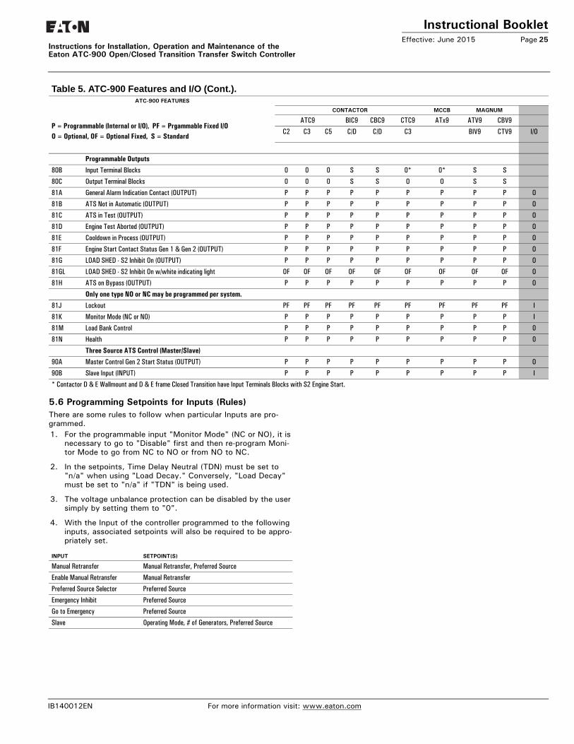
Instructional BookletEffective: June 2015 Page 25
Instructions for Installation, Operation and Maintenance of the Eaton ATC-900 Open/Closed Transition Transfer Switch Controller
5.6 Programming Setpoints for Inputs (Rules)There are some rules to follow when particular Inputs are pro-grammed. 1. For the programmable input "Monitor Mode" (NC or NO), it is
necessary to go to "Disable" first and then re-program Moni-tor Mode to go from NC to NO or from NO to NC.
2. In the setpoints, Time Delay Neutral (TDN) must be set to "n/a" when using "Load Decay." Conversely, "Load Decay" must be set to "n/a" if "TDN" is being used.
3. The voltage unbalance protection can be disabled by the user simply by setting them to "0".
4. With the Input of the controller programmed to the following inputs, associated setpoints will also be required to be appro-priately set.
Programmable Outputs
80B Input Terminal Blocks 0 0 0 S S 0* 0* S S
80C Output Terminal Blocks 0 0 0 S S O O S S
81A General Alarm Indication Contact (OUTPUT) P P P P P P P P P O
81B ATS Not in Automatic (OUTPUT) P P P P P P P P P O
81C ATS in Test (OUTPUT) P P P P P P P P P O
81D Engine Test Aborted (OUTPUT) P P P P P P P P P O
81E Cooldown in Process (OUTPUT) P P P P P P P P P O
81F Engine Start Contact Status Gen 1 & Gen 2 (OUTPUT) P P P P P P P P P O
81G LOAD SHED - S2 Inhibit On (OUTPUT) P P P P P P P P P O
81GL LOAD SHED - S2 Inhibit On w/white indicating light OF OF OF OF OF OF OF OF OF O
81H ATS on Bypass (OUTPUT) P P P P P P P P P O
Only one type NO or NC may be programmed per system.
81J Lockout PF PF PF PF PF PF PF PF PF I
81K Monitor Mode (NC or NO) P P P P P P P P P I
81M Load Bank Control P P P P P P P P P 0
81N Health P P P P P P P P P 0
Three Source ATS Control (Master/Slave)
90A Master Control Gen 2 Start Status (OUTPUT) P P P P P P P P P O
90B Slave Input (INPUT) P P P P P P P P P I
* Contactor D & E Wallmount and D & E frame Closed Transition have Input Terminals Blocks with S2 Engine Start.
Table 5. ATC-900 Features and I/O (Cont.).ATC-900 FEATURES
P = Programmable (Internal or I/O), PF = Prgammable Fixed I/OO = Optional, OF = Optional Fixed, S = Standard
CONTACTOR MCCB MAGNUM
ATC9 BIC9 CBC9 CTC9 ATx9 ATV9 CBV9
C2 C3 C5 C/D C/D C3 BIV9 CTV9 I/O
INPUT SETPOINT(S)
Manual Retransfer Manual Retransfer, Preferred Source
Enable Manual Retransfer Manual Retransfer
Preferred Source Selector Preferred Source
Emergency Inhibit Preferred Source
Go to Emergency Preferred Source
Slave Operating Mode, # of Generators, Preferred Source
IB140012EN For more information visit: www.eaton.com
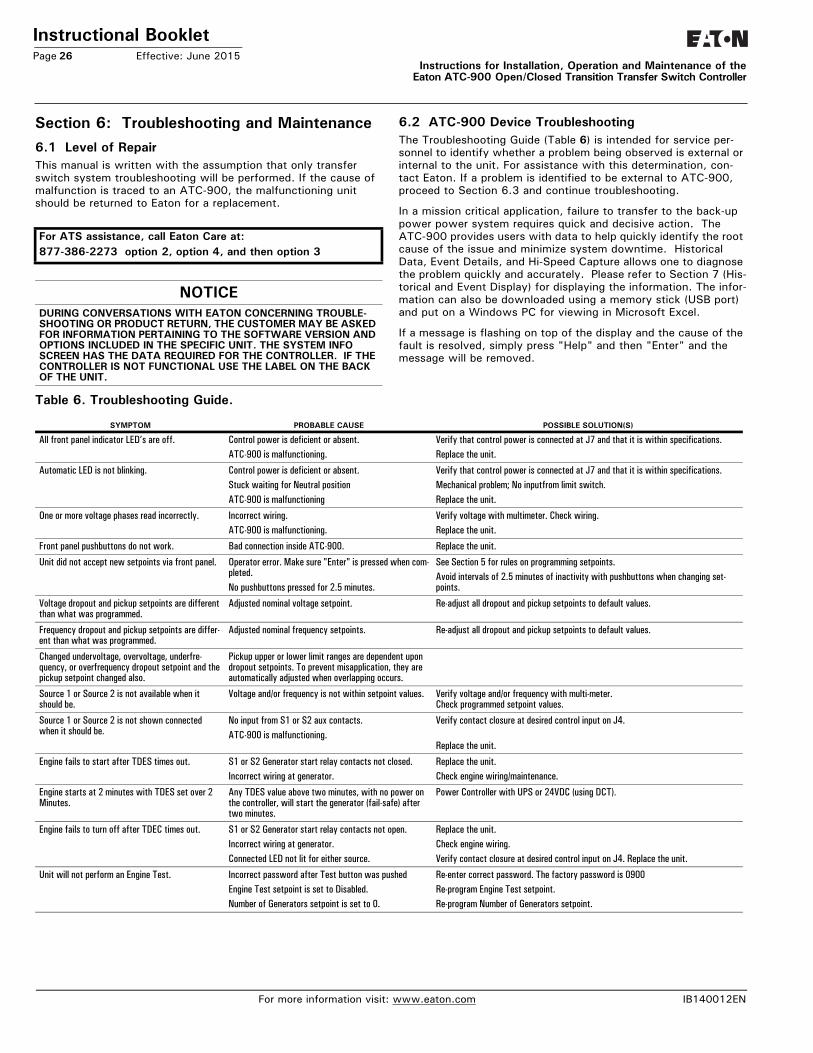
Instructional BookletPage 26 Effective: June 2015
Instructions for Installation, Operation and Maintenance of theEaton ATC-900 Open/Closed Transition Transfer Switch Controller
Section 6: Troubleshooting and Maintenance6.1 Level of RepairThis manual is written with the assumption that only transfer switch system troubleshooting will be performed. If the cause of malfunction is traced to an ATC-900, the malfunctioning unit should be returned to Eaton for a replacement.
6.2 ATC-900 Device TroubleshootingThe Troubleshooting Guide (Table 6) is intended for service per-sonnel to identify whether a problem being observed is external or internal to the unit. For assistance with this determination, con-tact Eaton. If a problem is identified to be external to ATC-900, proceed to Section 6.3 and continue troubleshooting.
In a mission critical application, failure to transfer to the back-up power power system requires quick and decisive action. The ATC-900 provides users with data to help quickly identify the root cause of the issue and minimize system downtime. Historical Data, Event Details, and Hi-Speed Capture allows one to diagnose the problem quickly and accurately. Please refer to Section 7 (His-torical and Event Display) for displaying the information. The infor-mation can also be downloaded using a memory stick (USB port) and put on a Windows PC for viewing in Microsoft Excel.
If a message is flashing on top of the display and the cause of the fault is resolved, simply press "Help" and then "Enter" and the message will be removed.
Table 6. Troubleshooting Guide.
For ATS assistance, call Eaton Care at:877-386-2273 option 2, option 4, and then option 3
NOTICEDURING CONVERSATIONS WITH EATON CONCERNING TROUBLE-SHOOTING OR PRODUCT RETURN, THE CUSTOMER MAY BE ASKED FOR INFORMATION PERTAINING TO THE SOFTWARE VERSION AND OPTIONS INCLUDED IN THE SPECIFIC UNIT. THE SYSTEM INFO SCREEN HAS THE DATA REQUIRED FOR THE CONTROLLER. IF THE CONTROLLER IS NOT FUNCTIONAL USE THE LABEL ON THE BACK OF THE UNIT.
SYMPTOM PROBABLE CAUSE POSSIBLE SOLUTION(S)
All front panel indicator LED’s are off. Control power is deficient or absent.ATC-900 is malfunctioning.
Verify that control power is connected at J7 and that it is within specifications.Replace the unit.
Automatic LED is not blinking. Control power is deficient or absent.Stuck waiting for Neutral positionATC-900 is malfunctioning
Verify that control power is connected at J7 and that it is within specifications.Mechanical problem; No inputfrom limit switch.Replace the unit.
One or more voltage phases read incorrectly. Incorrect wiring.ATC-900 is malfunctioning.
Verify voltage with multimeter. Check wiring.Replace the unit.
Front panel pushbuttons do not work. Bad connection inside ATC-900. Replace the unit.
Unit did not accept new setpoints via front panel. Operator error. Make sure "Enter" is pressed when com-pleted.No pushbuttons pressed for 2.5 minutes.
See Section 5 for rules on programming setpoints.Avoid intervals of 2.5 minutes of inactivity with pushbuttons when changing set-points.
Voltage dropout and pickup setpoints are different than what was programmed.
Adjusted nominal voltage setpoint. Re-adjust all dropout and pickup setpoints to default values.
Frequency dropout and pickup setpoints are differ-ent than what was programmed.
Adjusted nominal frequency setpoints. Re-adjust all dropout and pickup setpoints to default values.
Changed undervoltage, overvoltage, underfre-quency, or overfrequency dropout setpoint and the pickup setpoint changed also.
Pickup upper or lower limit ranges are dependent upon dropout setpoints. To prevent misapplication, they are automatically adjusted when overlapping occurs.
Source 1 or Source 2 is not available when it should be.
Voltage and/or frequency is not within setpoint values. Verify voltage and/or frequency with multi-meter. Check programmed setpoint values.
Source 1 or Source 2 is not shown connected when it should be.
No input from S1 or S2 aux contacts.ATC-900 is malfunctioning.
Verify contact closure at desired control input on J4.
Replace the unit.
Engine fails to start after TDES times out. S1 or S2 Generator start relay contacts not closed.Incorrect wiring at generator.
Replace the unit.Check engine wiring/maintenance.
Engine starts at 2 minutes with TDES set over 2 Minutes.
Any TDES value above two minutes, with no power on the controller, will start the generator (fail-safe) after two minutes.
Power Controller with UPS or 24VDC (using DCT).
Engine fails to turn off after TDEC times out. S1 or S2 Generator start relay contacts not open.Incorrect wiring at generator.Connected LED not lit for either source.
Replace the unit.Check engine wiring.Verify contact closure at desired control input on J4. Replace the unit.
Unit will not perform an Engine Test. Incorrect password after Test button was pushed Engine Test setpoint is set to Disabled.Number of Generators setpoint is set to 0.
Re-enter correct password. The factory password is 0900Re-program Engine Test setpoint.Re-program Number of Generators setpoint.
For more information visit: www.eaton.com IB140012EN
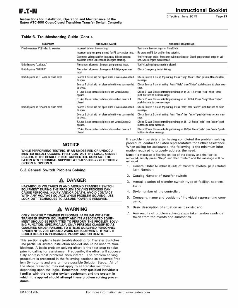
Instructional BookletEffective: June 2015 Page 27
Instructions for Installation, Operation and Maintenance of the Eaton ATC-900 Open/Closed Transition Transfer Switch Controller
6.3 General Switch Problem Solving
This section explains basic troubleshooting for Transfer Switches. The particular switch instruction booklet should be used to trou-bleshoot. A basic problem solving effort is the first step to take prior to calling for assistance. Frequently, the effort will success-fully address most problems encountered. The problem solving procedure is presented in the following sections as observed Prob-lem Symptoms and one or more possible Solution Steps. All of the steps presented may not apply to all transfer switches, depending upon the logic. Remember, only qualified individuals familiar with the transfer switch equipment and the system in which it is applied should attempt these problem solving proce-dures.
If a problem persists after having completed the problem solving procedure, contact an Eaton representative for further assistance. When calling for assistance, the following is the minimum infor-mation required to properly address the need:Note: If a message is flashing on top of the display and the fault is removed, simply press "Help" and then "Enter" and the message will be removed.
1. General Order Number (GO#) of transfer switch, plus related Item Number;
2. Catalog Number of transfer switch;
3. Actual location of transfer switch (type of facility, address, etc.);
4. Style number of the controller;
5. Company, name and position of individual representing com-pany;
6. Basic description of situation as it exists; and
7. Any results of problem solving steps taken and/or readings taken from the events and summaries.
Table 6. Troubleshooting Guide (Cont.).
SYMPTOM PROBABLE CAUSE POSSIBLE SOLUTION(S)
Plant exerciser (PE) failed to exercise. Incorrect date or time setting. Incorrect setpoint programmed for PE day and/or time.Generator voltage and/or frequency did not become available within 30 seconds of engine starting.
Verify real time settings for Time/Date.Re-program PE day and/or time setpoint.Verify voltage and/or frequency with multi-meter. Check programmed setpoint val-ues. Check engine maintenance.
Unit displays “Lockout.” No contact closure at Lockout programmed input. Verify Lockout input circuit is closed.
Unit displays “INHIBIT” No contact closure at Emergency Inhibit programmed Input
Check Emergency Inhibit Wiring.
Unit displays an S1 open or close error Source 1 circuit did not open when it was commanded to open.Source 1 circuit did not close when it was commanded to close.S1 Aux Close contacts did not open when Source 1 opened.S1 Aux Close contacts did not close when Source 1 closed
Check Source 1 circuit trip wiring. Press "Help" then "Enter" push-buttons to clear message. Check Source 1 circuit wiring. Press "Help" then "Enter" push-buttons to clear mes-sage. Check S1 Aux Close control input wiring on on J6-1,2. Press "Help" then "Enter" push-buttons to clear message. Check S1 Aux Close control input wiring on on J6-3,4. Press "Help" then "Enter" push-buttons to clear message.
Unit displays an S2 open or close error Source 2 circuit did not open when it was commanded to open.Source 2 circuit did not close when it was commanded to close.S2 Aux Close contacts did not open when Source 2 opened.S2 Aux Close contacts did not close when Source 2 closed
Check Source 2 circuit trip wiring. Press "help" then "enter" push-buttons to clear message. Check Source 2 circuit wiring. Press "help" then "enter" push-buttons to clear mes-sage. Check S2 Aux Close control input wiring on J6-1,2. Press "help" then "enter" push-buttons to clear message. Check S2 Aux Close control input wiring on J6-3,4. Press "help" then "enter" push-buttons to clear message.
NOTICEWHILE PERFORMING TESTING, IF AN UNDESIRED OR UNDOCU-MENTED RESULT OCCURS, FIRST CONTACT THE LOCAL GENSET DEALER. IF THE RESULT IS NOT CORRECTED, CONTACT THE EATON ATS TECHNICAL SUPPORT AT 1-877-386-2273 OPTION 2, OPTION 4, OPTION 3.
DANGERHAZARDOUS VOLTAGES IN AND AROUND TRANSFER SWITCH EQUIPMENT DURING THE PROBLEM SOLVING PROCESS CAN CAUSE PERSONAL INJURY AND/OR DEATH. AVOID CONTACT WITH ANY VOLTAGE SOURCE WHILE PROBLEM SOLVING. USE LOCK-OUT TECHNIQUES TO ASSURE POWER IS REMOVED.
WARNINGONLY PROPERLY TRAINED PERSONNEL FAMILIAR WITH THE TRANSFER SWITCH EQUIPMENT AND ITS ASSOCIATED EQUIP-MENT SHOULD BE PERMITTED TO PERFORM THE PROBLEM SOLV-ING FUNCTION. SPECIFICALLY, ONLY PERSONS CLASSIFIED AS QUALIFIED UNDER FAILURE, TO UTILIZE QUALIFIED PERSONNEL (UNDER NFPA 70E) SHOULD WORK ON EQUIPMENT. IF NOT, IT COULD RESULT IN PERSONNEL INJURY AND/OR DEATH.
IB140012EN For more information visit: www.eaton.com
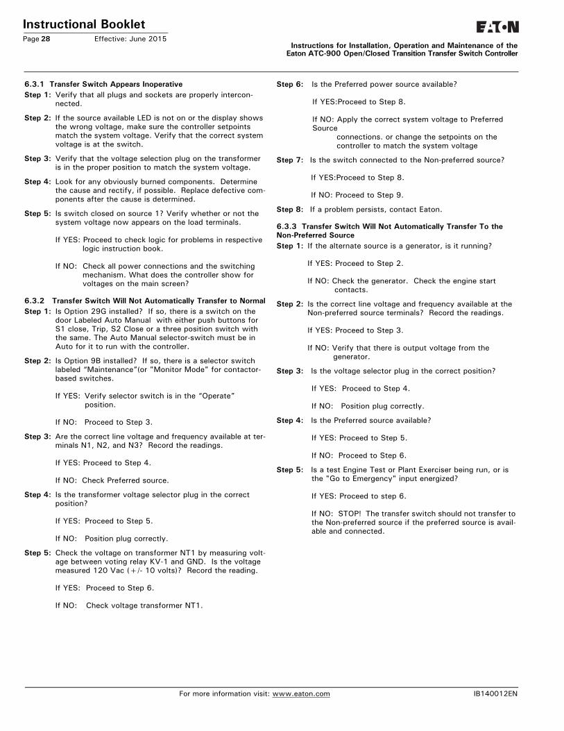
Instructional BookletPage 28 Effective: June 2015
Instructions for Installation, Operation and Maintenance of theEaton ATC-900 Open/Closed Transition Transfer Switch Controller
6.3.1 Transfer Switch Appears InoperativeStep 1: Verify that all plugs and sockets are properly intercon-
nected.
Step 2: If the source available LED is not on or the display shows the wrong voltage, make sure the controller setpoints match the system voltage. Verify that the correct system voltage is at the switch.
Step 3: Verify that the voltage selection plug on the transformer is in the proper position to match the system voltage.
Step 4: Look for any obviously burned components. Determine the cause and rectify, if possible. Replace defective com-ponents after the cause is determined.
Step 5: Is switch closed on source 1? Verify whether or not the system voltage now appears on the load terminals.
If YES: Proceed to check logic for problems in respective logic instruction book.
If NO: Check all power connections and the switching mechanism. What does the controller show for voltages on the main screen?
6.3.2 Transfer Switch Will Not Automatically Transfer to NormalStep 1: Is Option 29G installed? If so, there is a switch on the
door Labeled Auto Manual with either push buttons for S1 close, Trip, S2 Close or a three position switch with the same. The Auto Manual selector-switch must be in Auto for it to run with the controller.
Step 2: Is Option 9B installed? If so, there is a selector switch labeled “Maintenance”(or "Monitor Mode" for contactor-based switches.
If YES: Verify selector switch is in the “Operate” position.
If NO: Proceed to Step 3.
Step 3: Are the correct line voltage and frequency available at ter-minals N1, N2, and N3? Record the readings.
If YES: Proceed to Step 4.
If NO: Check Preferred source.
Step 4: Is the transformer voltage selector plug in the correct position?
If YES: Proceed to Step 5.
If NO: Position plug correctly.
Step 5: Check the voltage on transformer NT1 by measuring volt-age between voting relay KV-1 and GND. Is the voltage measured 120 Vac (+/- 10 volts)? Record the reading.
If YES: Proceed to Step 6.
If NO: Check voltage transformer NT1.
Step 6: Is the Preferred power source available?
If YES:Proceed to Step 8.
If NO: Apply the correct system voltage to Preferred Source
connections. or change the setpoints on the controller to match the system voltage
Step 7: Is the switch connected to the Non-preferred source?
If YES:Proceed to Step 8.
If NO: Proceed to Step 9.
Step 8: If a problem persists, contact Eaton.
6.3.3 Transfer Switch Will Not Automatically Transfer To the Non-Preferred SourceStep 1: If the alternate source is a generator, is it running?
If YES: Proceed to Step 2.
If NO: Check the generator. Check the engine start contacts.
Step 2: Is the correct line voltage and frequency available at the Non-preferred source terminals? Record the readings.
If YES: Proceed to Step 3.
If NO: Verify that there is output voltage from the generator.
Step 3: Is the voltage selector plug in the correct position?
If YES: Proceed to Step 4.
If NO: Position plug correctly.
Step 4: Is the Preferred source available?
If YES: Proceed to Step 5.
If NO: Proceed to Step 6.
Step 5: Is a test Engine Test or Plant Exerciser being run, or is the "Go to Emergency" input energized?
If YES: Proceed to step 6.
If NO: STOP! The transfer switch should not transfer to the Non-preferred source if the preferred source is avail-able and connected.
For more information visit: www.eaton.com IB140012EN
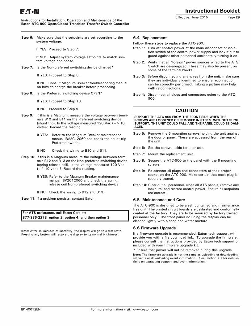
Instructional BookletEffective: June 2015 Page 29
Instructions for Installation, Operation and Maintenance of the Eaton ATC-900 Open/Closed Transition Transfer Switch Controller
Step 6: Make sure that the setpoints are set according to the system voltage.
If YES: Proceed to Step 7.
If NO: .Adjust system voltage setpoints to match sys-tem voltage and phase.
Step 7: Is the Non-preferred switching device charged?
If YES: Proceed to Step 8.
If NO: Consult Magnum Breaker troubleshooting manual on how to charge the breaker before proceeding.
Step 8: Is the Preferred switching device OPEN?
If YES: Proceed to Step 10.
If NO: Proceed to Step 9.
Step 9: If this is a Magnum, measure the voltage between termi-nals B10 and B11 on the Preferred switching device (shunt trip). Is the voltage measured 120 Vac (+/- 10 volts)? Record the reading.
If YES: Refer to the Magnum Breaker maintenance manual IB#2C12060 and check the shunt tripPreferred switch.
If NO: Check the wiring to B10 and B11.
Step 10: If this is a Magnum measure the voltage between termi-nals B12 and B13 on the Non-preferred switching device (spring release coil). Is the voltage measured 120 Vac (+/- 10 volts)? Record the reading.
If YES: Refer to the Magnum Breaker maintenance manual IB#2C12060 and check the springrelease coil Non-preferred switching device.
If NO: Check the wiring to B12 and B13.
Step 11: If a problem persists, contact Eaton.
Note: After 10 minutes of inactivity, the display will go to a dim state. Pressing any button will restore the display to its normal brightness.
6.4 ReplacementFollow these steps to replace the ATC-900.Step 1: Turn off control power at the main disconnect or isola-
tion switch of the control power supply and lock it out to guard against other personnel accidentally turning it on.
Step 2: Verify that all “foreign” power sources wired to the ATS Switch are de-energized. These may also be present on some of the terminal blocks.
Step 3: Before disconnecting any wires from the unit, make sure they are individually identified to ensure reconnection can be correctly performed. Taking a picture may help with re-connections.
Step 4: Disconnect all plugs and connectors going to the ATC-900.
Step 5: Remove the 6 mounting screws holding the unit against the door or panel. These are accessed from the rear of the unit.
Step 6: Set the screws aside for later use.
Step 7: Mount the replacement unit.
Step 8: Secure the ATC-900 to the panel with the 6 mounting screws.
Step 9: Re-connect all plugs and connectors to their proper socket on the ATC-900. Make certain that each plug is securely seated.
Step 10: Clear out all personnel, close all ATS panels, remove any lockouts, and restore control power. Ensure all setpoints are correct.
6.5 Maintenance and CareThe ATC-900 is designed to be a self contained and maintenance free unit. The printed circuit boards are calibrated and conformally coated at the factory. They are to be serviced by factory trained personnel only. The front panel including the display can be cleaned lightly with a soap and water mixture.
6.6 Firmware UpgradeIf a firmware upgrade is recommended, Eaton tech support will provide you with a file download link. To upgrade the firmware, please consult the instructions provided by Eaton tech support or included with your firmware upgrade kit. * Ensure that power will not be removed during this upgrade. Note: The firmware upgrade is not the same as uploading or downloading setpoints or downloading event information. See Section 7.1 for instruc-tions on extracting setpoint and event information.
For ATS assistance, call Eaton Care at:877-386-2273 option 2, option 4, and then option 3
CAUTIONSUPPORT THE ATC-900 FROM THE FRONT SIDE WHEN THE SCREWS ARE LOOSENED OR REMOVED IN STEP 5. WITHOUT SUCH SUPPORT, THE UNIT COULD FALL AND THE PANEL COULD BE DAM-AGED.
IB140012EN For more information visit: www.eaton.com
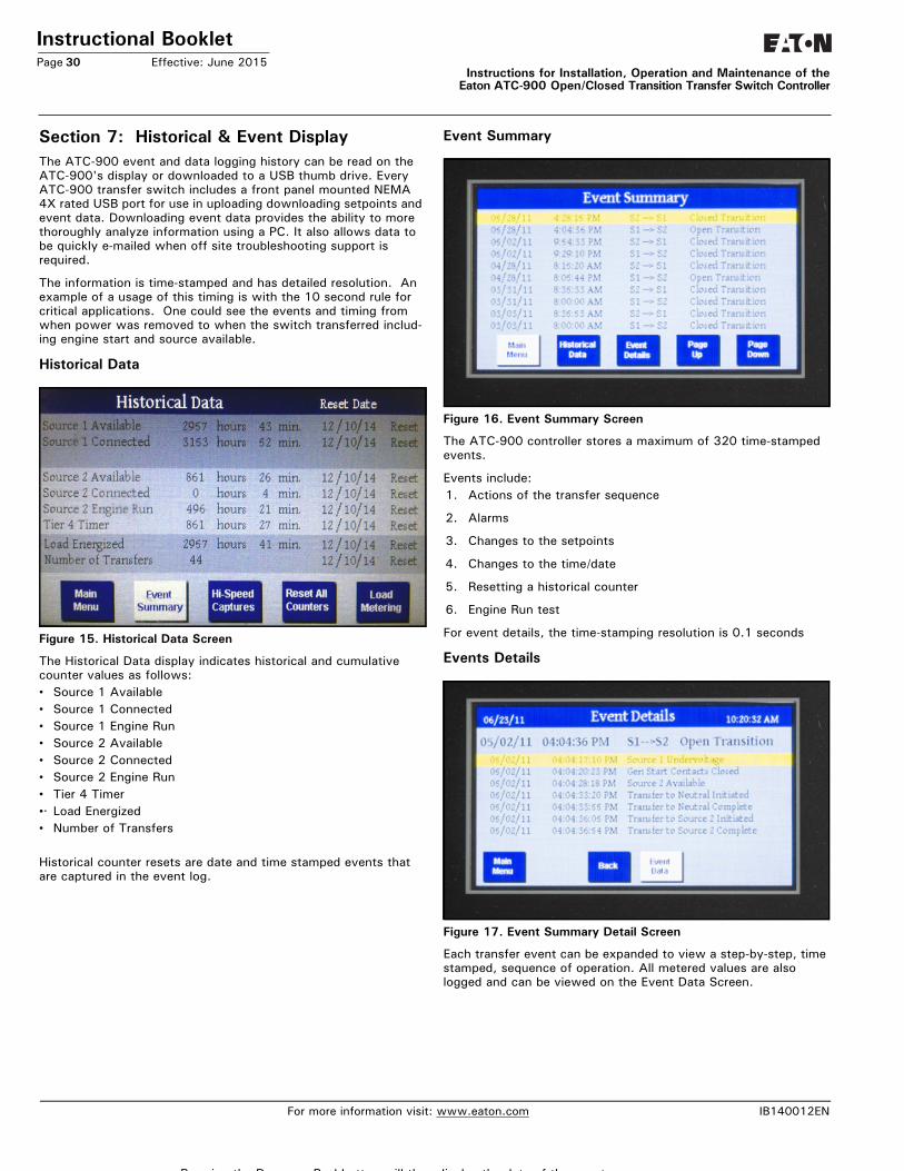
Instructional BookletPage 30 Effective: June 2015
Instructions for Installation, Operation and Maintenance of theEaton ATC-900 Open/Closed Transition Transfer Switch Controller
Section 7: Historical & Event DisplayThe ATC-900 event and data logging history can be read on the ATC-900's display or downloaded to a USB thumb drive. Every ATC-900 transfer switch includes a front panel mounted NEMA 4X rated USB port for use in uploading downloading setpoints and event data. Downloading event data provides the ability to more thoroughly analyze information using a PC. It also allows data to be quickly e-mailed when off site troubleshooting support is required.
The information is time-stamped and has detailed resolution. An example of a usage of this timing is with the 10 second rule for critical applications. One could see the events and timing from when power was removed to when the switch transferred includ-ing engine start and source available.
Historical Data
Figure 15. Historical Data Screen
The Historical Data display indicates historical and cumulative counter values as follows:• Source 1 Available• Source 1 Connected• Source 1 Engine Run• Source 2 Available• Source 2 Connected• Source 2 Engine Run• Tier 4 Timer•· Load Energized• Number of Transfers
Historical counter resets are date and time stamped events that are captured in the event log.
Event Summary
Figure 16. Event Summary Screen
The ATC-900 controller stores a maximum of 320 time-stamped events.
Events include:1. Actions of the transfer sequence
2. Alarms
3. Changes to the setpoints
4. Changes to the time/date
5. Resetting a historical counter
6. Engine Run test
For event details, the time-stamping resolution is 0.1 seconds
Events Details
Figure 17. Event Summary Detail Screen
Each transfer event can be expanded to view a step-by-step, time stamped, sequence of operation. All metered values are also logged and can be viewed on the Event Data Screen.
For more information visit: www.eaton.com IB140012EN
P i th D P hb tt ill th di l th d t f th t
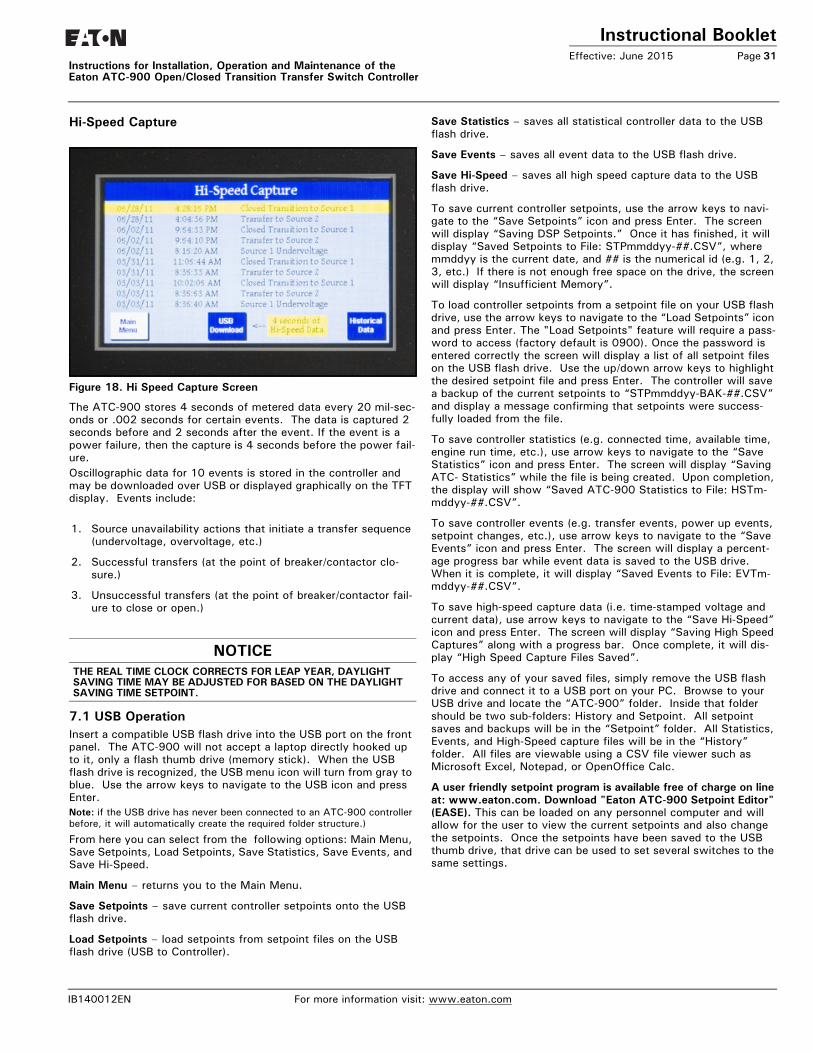
Instructional BookletEffective: June 2015 Page 31
Instructions for Installation, Operation and Maintenance of the Eaton ATC-900 Open/Closed Transition Transfer Switch Controller
Hi-Speed Capture
Figure 18. Hi Speed Capture Screen
The ATC-900 stores 4 seconds of metered data every 20 mil-sec-onds or .002 seconds for certain events. The data is captured 2 seconds before and 2 seconds after the event. If the event is a power failure, then the capture is 4 seconds before the power fail-ure. Oscillographic data for 10 events is stored in the controller and may be downloaded over USB or displayed graphically on the TFT display. Events include:
1. Source unavailability actions that initiate a transfer sequence (undervoltage, overvoltage, etc.)
2. Successful transfers (at the point of breaker/contactor clo-sure.)
3. Unsuccessful transfers (at the point of breaker/contactor fail-ure to close or open.)
7.1 USB OperationInsert a compatible USB flash drive into the USB port on the front panel. The ATC-900 will not accept a laptop directly hooked up to it, only a flash thumb drive (memory stick). When the USB flash drive is recognized, the USB menu icon will turn from gray to blue. Use the arrow keys to navigate to the USB icon and press Enter. Note: if the USB drive has never been connected to an ATC-900 controller before, it will automatically create the required folder structure.)
From here you can select from the following options: Main Menu, Save Setpoints, Load Setpoints, Save Statistics, Save Events, and Save Hi-Speed.
Main Menu – returns you to the Main Menu.
Save Setpoints – save current controller setpoints onto the USB flash drive.
Load Setpoints – load setpoints from setpoint files on the USB flash drive (USB to Controller).
Save Statistics – saves all statistical controller data to the USB flash drive.
Save Events – saves all event data to the USB flash drive.
Save Hi-Speed – saves all high speed capture data to the USB flash drive.
To save current controller setpoints, use the arrow keys to navi-gate to the “Save Setpoints” icon and press Enter. The screen will display “Saving DSP Setpoints.” Once it has finished, it will display “Saved Setpoints to File: STPmmddyy-##.CSV”, where mmddyy is the current date, and ## is the numerical id (e.g. 1, 2, 3, etc.) If there is not enough free space on the drive, the screen will display “Insufficient Memory”.
To load controller setpoints from a setpoint file on your USB flash drive, use the arrow keys to navigate to the “Load Setpoints” icon and press Enter. The "Load Setpoints" feature will require a pass-word to access (factory default is 0900). Once the password is entered correctly the screen will display a list of all setpoint files on the USB flash drive. Use the up/down arrow keys to highlight the desired setpoint file and press Enter. The controller will save a backup of the current setpoints to “STPmmddyy-BAK-##.CSV” and display a message confirming that setpoints were success-fully loaded from the file.
To save controller statistics (e.g. connected time, available time, engine run time, etc.), use arrow keys to navigate to the “Save Statistics” icon and press Enter. The screen will display “Saving ATC- Statistics” while the file is being created. Upon completion, the display will show “Saved ATC-900 Statistics to File: HSTm-mddyy-##.CSV”.
To save controller events (e.g. transfer events, power up events, setpoint changes, etc.), use arrow keys to navigate to the “Save Events” icon and press Enter. The screen will display a percent-age progress bar while event data is saved to the USB drive. When it is complete, it will display “Saved Events to File: EVTm-mddyy-##.CSV”.
To save high-speed capture data (i.e. time-stamped voltage and current data), use arrow keys to navigate to the “Save Hi-Speed” icon and press Enter. The screen will display “Saving High Speed Captures” along with a progress bar. Once complete, it will dis-play “High Speed Capture Files Saved”.
To access any of your saved files, simply remove the USB flash drive and connect it to a USB port on your PC. Browse to your USB drive and locate the “ATC-900” folder. Inside that folder should be two sub-folders: History and Setpoint. All setpoint saves and backups will be in the “Setpoint” folder. All Statistics, Events, and High-Speed capture files will be in the “History” folder. All files are viewable using a CSV file viewer such as Microsoft Excel, Notepad, or OpenOffice Calc.
A user friendly setpoint program is available free of charge on line at: www.eaton.com. Download "Eaton ATC-900 Setpoint Editor" (EASE). This can be loaded on any personnel computer and will allow for the user to view the current setpoints and also change the setpoints. Once the setpoints have been saved to the USB thumb drive, that drive can be used to set several switches to the same settings.
NOTICETHE REAL TIME CLOCK CORRECTS FOR LEAP YEAR, DAYLIGHT SAVING TIME MAY BE ADJUSTED FOR BASED ON THE DAYLIGHT SAVING TIME SETPOINT.
IB140012EN For more information visit: www.eaton.com
Instructional BookletPage 32 Effective: June 2015
Instructions for Installation, Operation and Maintenance of theEaton ATC-900 Open/Closed Transition Transfer Switch Controller
Appendix A: Feature List and Status Display MessagesFeature 1: Time Delay Normal to Emergency (TD Normal to Emer-gency) TDNE delays the transfer to the Non-preferred Source to permit stabilization of the Non-preferred power source before the transfer is made. This timer will begin the countdown from its setting value when the Non-preferred Source becomes available. If the Preferred Source should become available during the countdown of this timer, the timer will be aborted.
Feature 2: Time Delay Engine Start (TD Engine Start) TDES is used where the source is an engine generator. It delays initiation of the engine start circuit in order to override momentary power outages and/or fluctuations. This timer and the associated engine start circuit will operate with or without control power. There are two separate start circuits, one for each source when applications of two generators are selected, although the same Time Delay Engine Start (TDES) timer value is used for both. When one generator is selected, this timer’s engine start circuit will operate on generator 2 for source 2. If the source that is being transferred to has a generator and that source is already available, the TDES timer will be bypassed.
Feature 3: Time Delay Emergency to Normal (TD Emergency to Normal) TDEN delays the transfer to the Preferred Source to permit stabili-zation of the Preferred power source before the transfer is made. This timer will begin the countdown from its setting value when the Preferred Source becomes available. During the countdown of this timer, if the Preferred Source should become unavailable, the timer will be aborted. If the Preferred Source is available and the Non-preferred Source fails while the TDEN timer is counting down, the TDEN timer will be bypassed.
Feature 4: Time Delay Engine Cooldown (TDEC)TDEC permits the generator to run under a no-load condition after a transfer from the generator source has been made. Countdown timing begins when the transfer is completed. In applications where two generators are selected, the same cool-down is used for both.
Feature: System Nominal Frequency (NOMF) There are only two choices for system nominal frequency of the distribution system, 50 or 60 Hertz. The dropout/pickup, underfre-quency and overfrequency upper and lower setting limits are based on the nominal frequency value.
Feature: System Nominal Voltage (NOMV)
This refers to the standard system nominal RMS line to line volt-age. A wide range (110 to 600) of sensing voltage is available to be programmed. The undervoltage and overvoltage dropout/pickup setpoint limits are based on the nominal voltage setting.
Feature: Commit to Transfer During TDNE Timing (CTDNE)This feature provides for selection as to whether or not commit-ment to transfer is desired when Time Delay Normal to Emergency countdown has begun. If no commitment is chosen and the Pre-ferred Source returns to availability when the TDNE timer is count-ing down, the transfer is aborted and the engine generator (if applicable) is cooled down.
Feature: Engine Test Mode (TMODE)This feature provides selection of the type of test that can be initi-ated by the front panel Engine Test pushbutton. An engine test without transferring the load to it, or an engine test with a full transfer of the load to the engine, can be chosen. Load testing is fail-safe. If the generator fails during testing for any reason, the ATC-900 will signal the transfer switch to return to normal. If the disable test mode is chosen, the front panel pushbutton cannot be used to initiate a test.
Feature 6B: Test Engine Run This feature provides selection of the length of time in hours and minutes that the ATC-900 will enable the generator contacts dur-ing an Engine Test that was initiated from the front panel pushbut-ton or for the plant exerciser feature, if applicable. Separate run times can be set for each.
Feature 5J:Undervoltage Monitoring for Source 2 This feature constantly monitors Source 2 for an undervoltage condition. When the Source 2 voltage drops to a value equal to or below the undervoltage dropout setting, the source will become unavailable. The source’s voltage will then have to rise to a value that is equal to or above the pickup setting to become available again. This can be disabled in the setpoint settings under menu 3 in the Setpoints Dropouts/Pickups.
Underfrequency Monitoring for Source 2 This feature constantly monitors Source 2 for an underfrequency condition. When the Source 2 frequency drops to a value equal to or below the underfrequency dropout setting, the source will become unavailable. The source’s frequency will then have to rise to a value that is equal to or above the pickup setting to become available again. This can be disabled in the setpoint settings under menu 3 in the Setpoints Dropouts/Pickups.
Feature 5K: Overvoltage Monitoring for Source 2 This feature constantly monitors Source 2 for an overvoltage con-dition. When the Source 2 voltage rises to a value equal to or above the overvoltage dropout setting, the source will become unavailable. The source’s voltage will then have to drop to a value that is equal to or below the pickup setting to become available again. This can be disabled in the setpoint settings under menu 3 in the Setpoints Dropouts/Pickups.
Overfrequency Monitoring for Source 2 This feature constantly monitors Source 2 for an overfrequency condition. When the Source 2 frequency rises to a value equal to or above the overfrequency dropout setting, the source will become unavailable. The source’s frequency will then have to drop to a value that is equal to or below the pickup setting to become available again. This can be disabled in the setpoint set-tings under menu 3 in the Setpoints Dropouts/Pickups.
Feature 5L: Voltage Unbalance Monitoring for Source 2This feature constantly monitors Source 2 for a voltage unbalance condition using symmetrical components calculations. When the ratio of negative sequence to positive sequence voltage (V2/V1) exceeds the unbalance dropout setting the Unbalance/Phase Loss time delay starts counting. If the timer expires before the unbal-ance is resolved the source will become unavailable. The unbal-ance must drop to a value that is below the pickup setting to stop the timer or to become available after the timer expires. This can be disabled in the setpoint settings under menu 3 in the Setpoints Dropouts/Pickups.
CAUTIONCHANGING THE SYSTEM NOMINAL VOLTAGE OR FREQUENCY SET-POINTS WILL CAUSE PICKUP AND DROPOUT SETPOINTS TO CHANGE AUTOMATICALLY TO NEW DEFAULT VALUES.
For more information visit: www.eaton.com IB140012EN
Instructional BookletEffective: June 2015 Page 33
Instructions for Installation, Operation and Maintenance of the Eaton ATC-900 Open/Closed Transition Transfer Switch Controller
Feature 5M: Voltage Phase Loss for Source 2This feature constantly monitors Source 2 for a phase loss condi-tion using symmetrical components voltage calculations. When the ratio of negative sequence to positive sequence voltage (V2/V1) exceeds the phase loss dropout setting the Unbalance/Phase Loss time delay starts counting. If the timer expires before the phase loss is resolved the source will become unavailable. The phase loss must drop to a value that is below the pickup setting to stop the timer or to become available after the timer expires. This can be disabled in the setpoint settings under menu 3 in the Setpoints Dropouts/Pickups.
Feature 7B: Time Delay (TD Engine Failure) TDEF (0 to 6 seconds) is used where at least one source is an engine generator, TDEF will delay an available source from being declared unavailable in order to override momentary generator fluctuations. This time delay is only implemented when the load is connected to a generator source. TDEF is not displayed when the number of generators is zero. TDEF is used for both generators in the Dual Generator mode.
Feature 8C/8D: Transfer Time Delay BypassThis feature allows a pushbutton input to be used to bypass the timer for standard feature (TDNE) or standard feature (TDEN) indi-vidually, or both simultaneously. This pushbutton is on the front of the controller (pushing "Enter" and "Help" at the same time. One could also wire in a pushbutton remote switch to any of the Inputs to do the same function. This feature is usually used in testing when it is not desirable to wait for completion of the tim-ing sequence.
Feature 9B: Maintenance Mode (Monitor Mode) This is a two position switch that is labeled Maintenance Mode for breakers, power breakers (MG) and Monitor Mode for contractors. This will place the controller in Monitor Mode and no transfers will occur and the controller will continue to monitor the availability, connected state, and voltages.
Feature 9C MonitorThis is a two position switch that will place the controller into Monitor. It will use one of the inputs of the controller and is used for contactors. When used, no transfers will occur and the con-troller will continue to monitor the availability, connected state, and voltages.
Feature 10A: Preferred Source Selection This feature permits the selection of either source (1, 2 or None, or External) as the Preferred (or Normal) Source. The Normal Source is the source that the switch always looks to for availabil-ity so that it can transfer to it. When two generators are selected and the switch has transferred to the Emergency Source, the ATC-900 will constantly be waiting and attempting to start the generator on the Preferred Source so that it may return to it. If NONE is chosen, the Preferred Source or the Normal Source will be the source that is presently attached to the load. This can be changed in the controller setpoints or one may wire up a two posi-tion switch into one of the programmable inputs (controller set-point must be set to External).
Feature 15G & 15HThis feature, mainly for contactors, are Source Position Contacts (to Terminal Blocks) for Source 1 and Source 2. Up to 10 each position contacts for Source 1 and Source 2 may be obtained using the outputs of the controller and the I/O Modules if desired. 15G and 15H are contacts which indicate to the position even if power is removed. For Closed Transition type switches these are always available. For Open type switches, 15G and 15H are an option.
Feature 16: External Overcurrent Protection When integral overcurrent protection is provided for either one or both sources, the need for separate upstream overcurrent protec-tion (in most instances) is eliminated. With this factory installed feature in the ATC-900, further automatic transfer operation is locked-out until the appropriate source breaker is reset. It will continue to monitor the voltage availability and the switch posi-tions.
Feature 16T: Load Current Unbalance Monitoring (must have option 18J DCT Module)This feature constantly monitors the load current for an unbalance condition using symmetrical components calculations. The current unbalance enable threshold is used to avoid spurious unbalance detections under light loads. The unbalance calculations are not performed until the average load current exceeds this threshold. When the ratio of negative sequence to positive sequence current (I2/I1) exceeds the unbalance dropout setting the Unbalance/Phase Loss time delay starts counting. If the timer expires before the unbalance is resolved the connected source will become unavailable. The unbalance must drop to a value that is below the pickup setting to stop the timer or to become available after the timer expires. This can be disabled in the setpoint settings under menu 3 in the Setpoints Dropouts/Pickups.
Feature 23: Plant Exerciser This feature provides for the automatic test operation of the gen-erator ata pre-selected weekly interval. When the test is running, pressing and releasing the Engine Test pushbutton will cancel the test. The day of the week, hour, and minute that exercising is desired can be programmed into the ATC-900. Up to twelve sepa-rate month and day combinations can be set. The type of test, whether a load transfer or just an engine test, can also be selected. Load testing is fail-safe. If the generator fails during test-ing for any reason, the ATC-900 will signal the transfer switch to return to the Preferred source. The ATC-900 is factory shipped with this feature set to off.
Feature 26D: Go To Emergency This feature enables an external contact closure to initiate a trans-fer from the Preferrd Source to the Non-preferred Source. If the external contact is closed and the Non-preferred Source fails, the ATC-900 will transfer the load back to the Preferred Source.
Feature 26J: Undervoltage Monitoring for Source 1 This feature constantly monitors Source 1 for an undervoltage condition. When the Source 1 voltage drops to a value equal to or below the undervoltage dropout setting, the source will become unavailable. The source’s voltage will then have to rise to a value that is equal to or above the pickup setting to become available again. This can be disabled in the setpoint settings under menu 3 in the Setpoints Dropouts/Pickups.
Underfrequency Monitoring for Source 1 This feature constantly monitors Source 1 for an underfrequency condition. When the Source 1 frequency drops to a value equal to or below the underfrequency dropout setting, the source will become unavailable. The source’s frequency will then have to rise to a value that is equal to or above the pickup setting to become available again. This can be disabled in the setpoint settings under menu 3 in the Setpoints Dropouts/Pickups.
IB140012EN For more information visit: www.eaton.com

Instructional BookletPage 34 Effective: June 2015
Instructions for Installation, Operation and Maintenance of theEaton ATC-900 Open/Closed Transition Transfer Switch Controller
Feature 26K: Overvoltage Monitoring for Source 1 This feature constantly monitors Source 1 for an overvoltage con-dition. When the Source 1 voltage rises to a value equal to or above the overvoltage dropout setting, the source will become unavailable. The source’s voltage will then have to drop to a value that is equal to or below the pickup setting to become available again. This can be disabled in the setpoint settings under menu 3 in the Setpoints Dropouts/Pickups.
Overfrequency Monitoring for Source 1 This feature constantly monitors Source 1 for an overfrequency condition. When the Source 1 frequency rises to a value equal to or above the overfrequency dropout setting, the source will become unavailable. The source’s frequency will then have to drop to a value that is equal to or below the pickup setting to become available again. This can be disabled in the setpoint set-tings under menu 3 in the Setpoints Dropouts/Pickups.
Feature 26L: Voltage Unbalance Monitoring for Source 1This feature constantly monitors Source 1 for a voltage unbalance condition using symmetrical components calculations. When the ratio of negative sequence to positive sequence voltage (V2/V1) exceeds the unbalance dropout setting the Unbalance/Phase Loss time delay starts counting. If the timer expires before the unbal-ance is resolved the source will become unavailable. The unbal-ance must drop to a value that is below the pickup setting to stop the timer or to become available after the timer expires. This can be disabled in the setpoint settings under menu 3 in the Setpoints Dropouts/Pickups.
Feature 26M: Voltage Phase Loss for Source 1This feature constantly monitors Source 1 for a phase loss condi-tion using symmetrical components voltage calculations. When the ratio of negative sequence to positive sequence voltage (V2/V1) exceeds the phase loss dropout setting the Unbalance/Phase Loss time delay starts counting. If the timer expires before the phase loss is resolved the source will become unavailable. The phase loss must drop to a value that is below the pickup setting to stop the timer or to become available after the timer expires. This can be disabled in the setpoint settings under menu 3 in the Set-points Dropouts/Pickups.
Feature 29J: Manual RetransferThis feature provides for a selection between an automatic trans-fer and re-transfer mode or a manual pushbutton re-transfer to Normal from the Emergency Source mode. If this option is not selected the factory default selection is automatic.
Feature 32A: Time Delay Neutral This feature provides a time delay in the transfer switch Neutral position when both breakers/contactors are open. This delay takes place when the load is transferred in either direction to prevent excessive in-rush currents due to out-of-phase switching of large motor loads. This feature is not available with the Neutral Load Sense Delay (TDNLD) feature.
Feature 32B: Load Voltage Decay This feature utilizes the load voltage measurements to sense back EMF that is generated when the transfer switch is in the Neutral position. It provides a delay in transfer in either direction if an unacceptable level is sensed as established by a customer pro-grammed level. The transfer will not take place until the back EMF decays below the acceptable programmed level. This feature has a separate setting of enabling or disabling the operation. If disabled, the transfer switch will not delay in the Neutral position and will transfer between the sources as fast as possible. This feature is not available with the Time Delay Neutral (TDN) Feature 32A.
Feature 32C: In-Phase/Load Voltage DecayIn-phase transition is a feature that will allow a transfer between two live sources only when the phase difference between the two sources is near zero. This is an open transition transfer that pre-vents in-rush currents from exceeding normal starting currents in the case where motor loads are being transferred.Load Voltage Decay utilizes the load voltage measurements to sense back EMF that is generated when the transfer switch is in the Neutral position. It provides a delay in transfer in either direc-tion if an unacceptable level is sensed as established by a cus-tomer programmed level. The transfer will not take place until the back EMF decays below the acceptable programmed level. This feature has a separate setting of enabling or disabling the opera-tion. If disabled, the transfer switch will not delay in the Neutral position and will transfer between the sources as fast as possible. This feature is not available with the Time Delay Neutral (TDN) Feature 32A.
Feature 32D: In-Phase/Time Delay Neutral (3 Position)In-phase transition is a feature that will allow a transfer between two live sources only when the phase difference between the two sources is near zero. This is an open transition transfer that pre-vents in-rush currents from exceeding normal starting currents in the case where motor loads are being transferred.Time Delay Neutral provides a time delay in the transfer switch Neutral position when both breakers/contactors are open. This delay takes place when the load is transferred in either direction to prevent excessive in-rush currents due to out-of-phase switching of large motor loads. This feature is not available with the Neutral Load Sense Delay feature.
Feature 32F: In-Phase TransitionProvides In-Phase transition, which is a feature that will permit a transfer or re-transfer between two available sources that have a phase angle difference of eight degrees or less. The In-Phase tran-sition feature includes permissible frequency difference and syn-chronization time setpoints. In the event Source 1 and Source 2 fail to synchronize within the permitted frequency difference and time, the alarm relay will energize and “Failed to Sync” will be dis-played on Line 1. After resetting the alarm, another in-phase tran-sition may be attempted or a non-synchronized transfer may be initiated by failing the connected source. The adjustable frequency difference is 0.0 to 3.0 Hz. If the synchronization does not occur within a specified amount of time, the alarm relay will energize and the failure will be logged into the Transfer History as either “Sync Fail - Freq” or “Sync Fail - Phase” depending on whether the frequency difference or the phase difference was excessive.
Feature 35A: Pre-Transfer Signal Typically associated with elevator controls, this feature provides of a form C output to remotely signal an elevator that a re-transfer is about to take place. If there is a power outage, the Pre-Transfer (TPRE) is skipped. The ATC-900 has a programmed pre-transfer delay timer that can be set from 0 to 120 seconds. Timers, such as TDNE, will time out before the PRE-Transfer signal occurs.
Feature 35D: Post-Transfer SignalThis feature provides a form C output from the ATC-900 to signal that the switch did transfer. It can be set for 0 to 120 seconds. The Post Transfer output is enabled during neutral (Time Delay Neutral) but it does not start to count down TDPOST until con-nected to the new source.
For more information visit: www.eaton.com IB140012EN
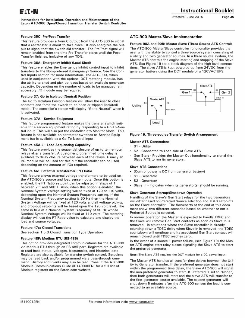
Instructional BookletEffective: June 2015 Page 35
Instructions for Installation, Operation and Maintenance of the Eaton ATC-900 Open/Closed Transition Transfer Switch Controller
Feature 35C: Pre/Post TransferThis feature provides a form C output from the ATC-900 to signal that a re-transfer is about to take place. It also energizes the out-put to signal that the switch did transfer. The Pre/Post signal will remain enabled from the time Pre-Transfer starts until the Post-Transfer finishes, inclusive of any TDN.
Feature 36A: Emergency Inhibit (Load Shed) This feature enables the Emergency Inhibit control input to inhibit transfers to the Non-preferred (Emergency) Source. See the Con-trol Inputs section for more information. The ATC-900, when used in conjunction with the optional DCT metering module, has the ability to shed and pick up loads based on available generator capacity. Depending on the number of loads to be managed, an accessory I/O module may be required.
Feature 37: Go to Isolated (Neutral) Position The Go to Isolation Position feature will allow the user to close contacts and force the switch to an open or tripped (isolated) mode. The controller's screen will display “Go to Neutral” when it is activated.
Feature 37A: Service Equipment This factory programmed feature makes the transfer switch suit-able for a service equipment rating by responding to a Go-To-Neu-tral input. This will also put the controller into Monitor Mode. This feature is not available on contactor switches as Service Equip-ment but is available as a Go To Neutral input.
Feature 45A-L: Load Sequencing Capability This feature provides the sequential closure of up to ten remote relays after a transfer. A customer programmed time delay is available to delay closure between each of the relays. Usually an I/O module will be used for this but the controller can be used depending on the amount of I/Os required.
Feature 46: Potential Transformer (PT) RatioThis feature allows external voltage transformers to be used on the ATC-900’s source and load sense inputs. Once this option is enabled, the PT Ratio setpoint can be adjusted in steps of 1, between 2:1 and 500:1. Also, when this option is enabled, the Nominal System Voltage setting will be fixed at 120 or 110 volts, depending upon the Nominal System Frequency setting. If the Nominal System Frequency setting is 60 Hz then the Nominal System Voltage will be fixed at 120 volts and all voltage pick-up and drop-out setpoints will be based upon the 120 volt level. The same is true of a Nominal System Frequency of 50 Hz whose Nominal System Voltage will be fixed at 110 volts. The metering display will use the PT Ratio value to calculate and display the load and source voltages.
Feature 47x: Closed TransitionsSee section 1.5.3 Closed Transition Type Operation
Feature 48F: Modbus RTU (RS-485)This option provides integrated communications for the ATC-900 via Modbus RTU through an RS-485 port. Registers are available to read back status, voltages, frequencies, and historical data. Registers are also available for transfer switch control. Setpoints may be read back and/or programmed via a pass-through com-mand. History and Events may also be read. Consult the ATC-900 Modbus Communications Guide (IB140006EN) for a full list of Modbus registers on the Eaton.com website.
ATC-900 Master/Slave Implementation
Feature 90A and 90B: Master Slave (Three Source ATS Control)The ATC-900 Master/Slave controller functionality provides the user with the ability to control a three source system consisting of a utility and two generator sources. In a three source system, the Master ATS controls the engine starting and stopping of the Slave ATS. See Figure 19 for a block diagram of the high level connec-tions. The slave ATS is kept powered up from 24VDC from the generator battery using the DCT module or a 120VAC UPS.
Figure 19. Three-source Transfer Switch Arrangement
Master ATS Connections• S1 - Utility• S2 - Connected to Load side of Slave ATS• Gen Start - Provides the Master Out functionality to signal the
Slave ATS to run its generators.
Slave ATS Connections• (Control power is DC from generator battery)• S1 - Generator• S2 - Generator• Slave In - Indicates when its generator(s) should be running.
Slave Generator Startup/Shutdown OperationHandling of the Slave's Gen Start relays for the two generators will differ based on Preferred Source selection and TDES setpoints on the Slave controller. The flowcharts at the end of this docu-ment show two different scenarios based on whether or not a Preferred Source is selected.In normal operation the Master is expected to handle TDEC and the Slave will remove Gen Start contacts as soon as Slave In is removed. In situations where the Slave controller is already counting down a TDEC delay when Slave In is removed, the TDEC countdown will continue and its associated Gen Start contact will remain closed until TDEC reaches zero.In the event of a source 1 power failure, (see Figure 19) the Mas-ter ATS engine start relay closes signaling the Slave ATS to start the preferred generator.
Note: The Slave ATS requires the DCT module for a DC power input.
The Master ATS handles all transfer time delays between the Util-ity to Generator transfer. If the preferred generator does not start within the programmed time delay, the Slave ATC-900 will signal the non-preferred generator to start. If Preferred is set to "None", then both generators will start and the slave ATS will transfer to the first generator source available. The second generator will shut down 5 minutes after the ATC-900 senses the load is con-nected to an available source.
Slave ATS
S2
Master ATS
S1Gen 1 Gen 2
Slave In
S2
Gen Start
S1
Utility
Load
IB140012EN For more information visit: www.eaton.com

Instructional BookletPage 36 Effective: June 2015 Instructions for Installation, Operation and Maintenance of the
Eaton ATC-900 Open/Closed Transition Transfer Switch Controller
Slave Generator Failure / TransfersGenerators attached to the Slave controller can fail in two ways: they can fail to start, or fail while providing power to the load. Currently, the ATC-900 only reports a Generator Fault Alarm dur-ing starting if a generator fails to start within 90 seconds when in test or plant exercise modes. In these cases, the Gen Start con-tact is opened after the 90 second timeout. In non-test/exercise modes the Gen Start contact is kept closed until either the genera-tor starts or the reason for attempting to start the generator is removed (for example, the Slave In signal is removed).Failure of the generator providing power to the load is handled by reporting a Generator Fail Alarm and transferring to the second generator with normal time delays for TDES, TDEC, TDEN/TDNE, etc. The Master controller sees this only as a failure of S2, and will react as with any other failure of S2. The Generator Fail Alarm remains active until either manually cleared or until Slave In is removed and re-asserted to start a new session.Once a generator fails, the other generator will be kept on until either the Generator Fail Alarm is manually cleared, or Slave In is removed. This is true even if the failed generator restarts and load is transferred back to it, e.g. if the failed generator is the preferred source.
Pre Transfer, Post Transfer, Load Sequencing, and Load ShedThe use of Pre Transfer, Post Transfer, Load Sequencing and Load Shed relays must be carefully considered in view of the dual trans-fer switches. It may be necessary to mirror these functions on both controllers and parallel/series relay outputs from both control-lers to ensure proper control during any transfer. There will be no special handling of these signals based on Master/Slave setup in Phase 1 ATC-900 controllers.
Engine Test / Plant ExerciseA Master initiated Engine Test or Plant Exercise will cause the Slave to respond just as it does for a normal transfer. A Slave ini-tiated Engine Test or Plant Exercise is limited to "run only" since the slave has no way of initiating a Master load transfer. The Engine Test has it's own separate setpoints for times and types.
For more information visit: www.eaton.com IB140012EN
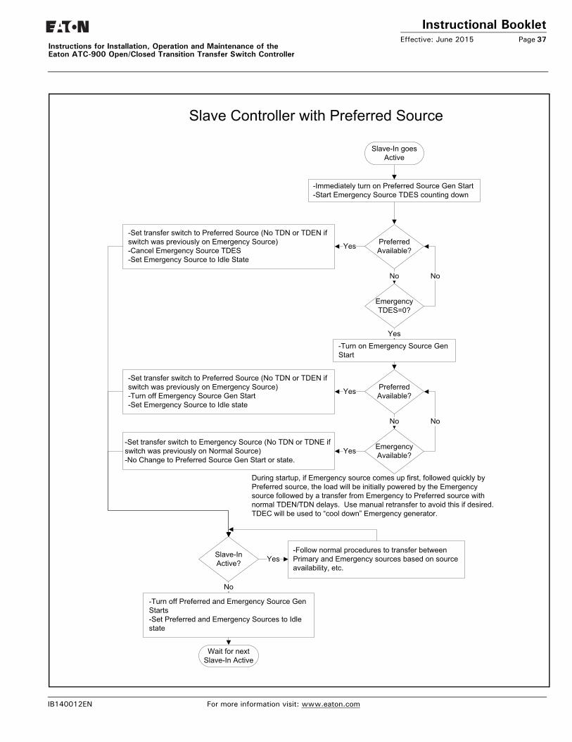
Instructional BookletEffective: June 2015 Page 37
Instructions for Installation, Operation and Maintenance of the Eaton ATC-900 Open/Closed Transition Transfer Switch Controller
-Immediately turn on Preferred Source Gen Start-Start Emergency Source TDES counting down
Preferred Available?
Emergency TDES=0?
-Turn on Emergency Source Gen Start
Yes
No No
Emergency Available?
-Set transfer switch to Preferred Source (No TDN or TDEN if switch was previously on Emergency Source)-Cancel Emergency Source TDES-Set Emergency Source to Idle State
Yes
Preferred Available?
-Set transfer switch to Preferred Source (No TDN or TDEN if switch was previously on Emergency Source)-Turn off Emergency Source Gen Start-Set Emergency Source to Idle state
Yes
No No
-Set transfer switch to Emergency Source (No TDN or TDNE if switch was previously on Normal Source)-No Change to Preferred Source Gen Start or state.
Yes
Slave-In Active?
-Turn off Preferred and Emergency Source Gen Starts-Set Preferred and Emergency Sources to Idle state
-Follow normal procedures to transfer between Primary and Emergency sources based on source availability, etc.
Wait for next Slave-In Active
Slave-In goes Active
Yes
No
Slave Controller with Preferred Source
During startup, if Emergency source comes up first, followed quickly by Preferred source, the load will be initially powered by the Emergency source followed by a transfer from Emergency to Preferred source with normal TDEN/TDN delays. Use manual retransfer to avoid this if desired.TDEC will be used to “cool down” Emergency generator.
IB140012EN For more information visit: www.eaton.com
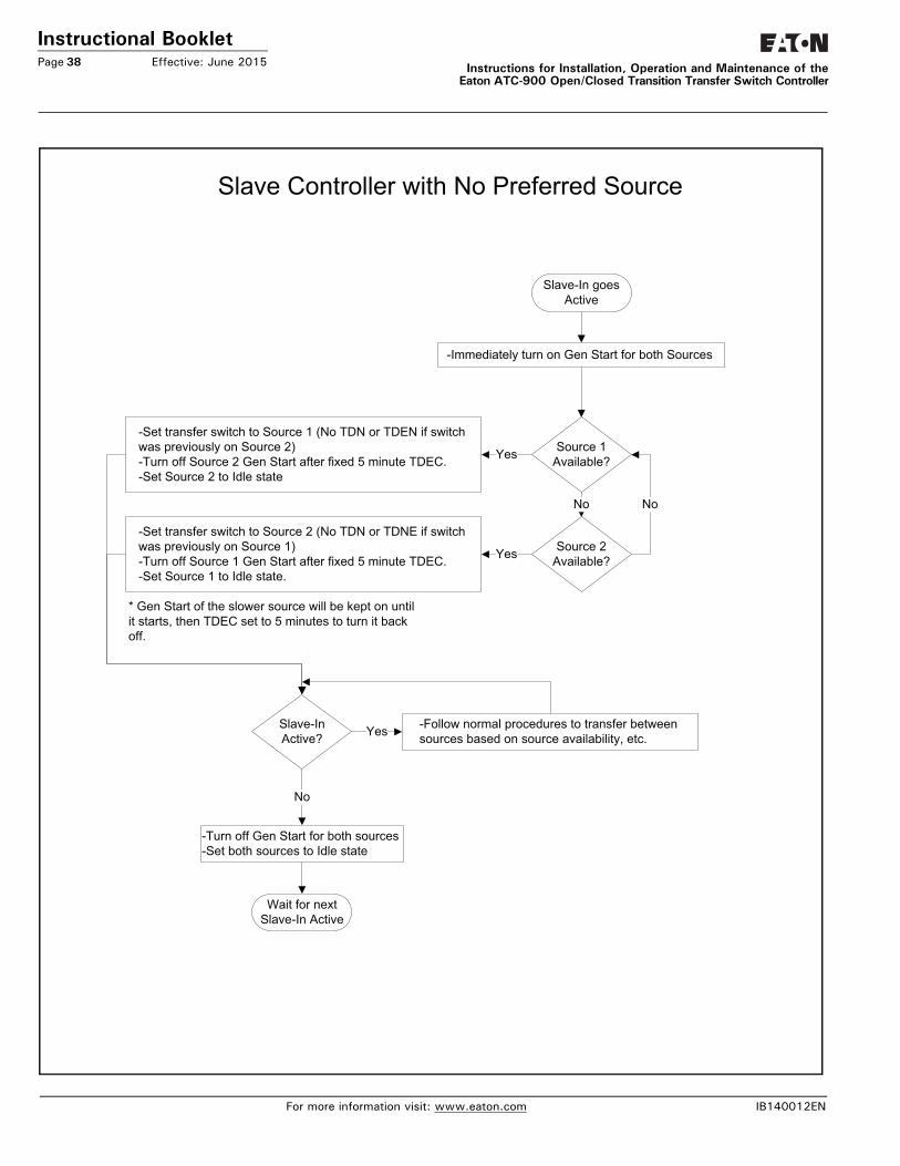
Instructional BookletPage 38 Effective: June 2015 Instructions for Installation, Operation and Maintenance of the
Eaton ATC-900 Open/Closed Transition Transfer Switch Controller
-Immediately turn on Gen Start for both Sources
Source 2 Available?
Source 1 Available?
-Set transfer switch to Source 1 (No TDN or TDEN if switch was previously on Source 2)-Turn off Source 2 Gen Start after fixed 5 minute TDEC.-Set Source 2 to Idle state
Yes
No No
-Set transfer switch to Source 2 (No TDN or TDNE if switch was previously on Source 1)-Turn off Source 1 Gen Start after fixed 5 minute TDEC.-Set Source 1 to Idle state.
Yes
Slave-In Active?
-Turn off Gen Start for both sources-Set both sources to Idle state
-Follow normal procedures to transfer between sources based on source availability, etc.
Slave-In goes Active
Yes
No
Slave Controller with No Preferred Source
* Gen Start of the slower source will be kept on until it starts, then TDEC set to 5 minutes to turn it back off.
For more information visit: www.eaton.com IB140012EN
Wait for next Slave-In Active
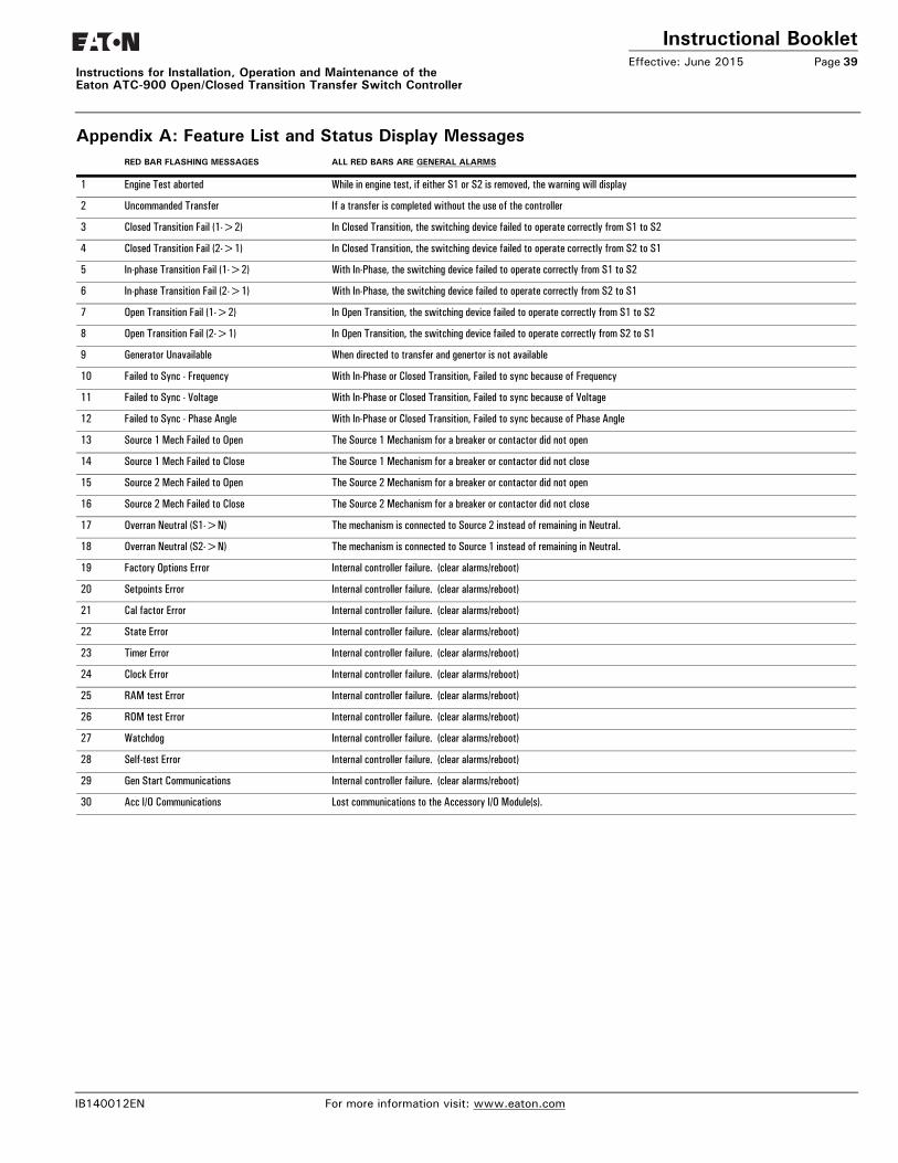
Instructional BookletEffective: June 2015 Page 39
Instructions for Installation, Operation and Maintenance of the Eaton ATC-900 Open/Closed Transition Transfer Switch Controller
Appendix A: Feature List and Status Display MessagesRED BAR FLASHING MESSAGES ALL RED BARS ARE GENERAL ALARMS
1 Engine Test aborted While in engine test, if either S1 or S2 is removed, the warning will display
2 Uncommanded Transfer If a transfer is completed without the use of the controller
3 Closed Transition Fail (1->2) In Closed Transition, the switching device failed to operate correctly from S1 to S2
4 Closed Transition Fail (2->1) In Closed Transition, the switching device failed to operate correctly from S2 to S1
5 In-phase Transition Fail (1->2) With In-Phase, the switching device failed to operate correctly from S1 to S2
6 In-phase Transition Fail (2->1) With In-Phase, the switching device failed to operate correctly from S2 to S1
7 Open Transition Fail (1->2) In Open Transition, the switching device failed to operate correctly from S1 to S2
8 Open Transition Fail (2->1) In Open Transition, the switching device failed to operate correctly from S2 to S1
9 Generator Unavailable When directed to transfer and genertor is not available
10 Failed to Sync - Frequency With In-Phase or Closed Transition, Failed to sync because of Frequency
11 Failed to Sync - Voltage With In-Phase or Closed Transition, Failed to sync because of Voltage
12 Failed to Sync - Phase Angle With In-Phase or Closed Transition, Failed to sync because of Phase Angle
13 Source 1 Mech Failed to Open The Source 1 Mechanism for a breaker or contactor did not open
14 Source 1 Mech Failed to Close The Source 1 Mechanism for a breaker or contactor did not close
15 Source 2 Mech Failed to Open The Source 2 Mechanism for a breaker or contactor did not open
16 Source 2 Mech Failed to Close The Source 2 Mechanism for a breaker or contactor did not close
17 Overran Neutral (S1->N) The mechanism is connected to Source 2 instead of remaining in Neutral.
18 Overran Neutral (S2->N) The mechanism is connected to Source 1 instead of remaining in Neutral.
19 Factory Options Error Internal controller failure. (clear alarms/reboot)
20 Setpoints Error Internal controller failure. (clear alarms/reboot)
21 Cal factor Error Internal controller failure. (clear alarms/reboot)
22 State Error Internal controller failure. (clear alarms/reboot)
23 Timer Error Internal controller failure. (clear alarms/reboot)
24 Clock Error Internal controller failure. (clear alarms/reboot)
25 RAM test Error Internal controller failure. (clear alarms/reboot)
26 ROM test Error Internal controller failure. (clear alarms/reboot)
27 Watchdog Internal controller failure. (clear alarms/reboot)
28 Self-test Error Internal controller failure. (clear alarms/reboot)
29 Gen Start Communications Internal controller failure. (clear alarms/reboot)
30 Acc I/O Communications Lost communications to the Accessory I/O Module(s).
IB140012EN For more information visit: www.eaton.com
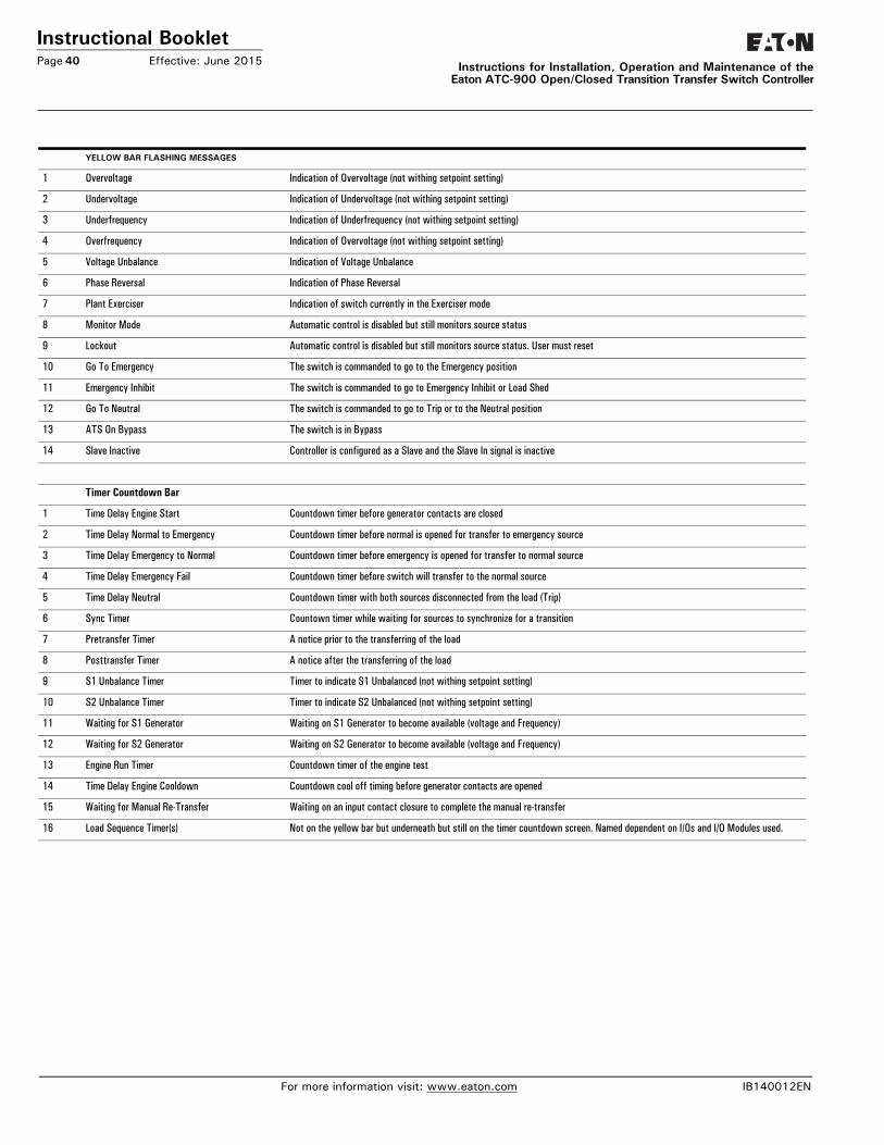
Instructional BookletPage 40 Effective: June 2015 Instructions for Installation, Operation and Maintenance of the
Eaton ATC-900 Open/Closed Transition Transfer Switch Controller
YELLOW BAR FLASHING MESSAGES
1 Overvoltage Indication of Overvoltage (not withing setpoint setting)
2 Undervoltage Indication of Undervoltage (not withing setpoint setting)
3 Underfrequency Indication of Underfrequency (not withing setpoint setting)
4 Overfrequency Indication of Overvoltage (not withing setpoint setting)
5 Voltage Unbalance Indication of Voltage Unbalance
6 Phase Reversal Indication of Phase Reversal
7 Plant Exerciser Indication of switch currently in the Exerciser mode
8 Monitor Mode Automatic control is disabled but still monitors source status
9 Lockout Automatic control is disabled but still monitors source status. User must reset
10 Go To Emergency The switch is commanded to go to the Emergency position
11 Emergency Inhibit The switch is commanded to go to Emergency Inhibit or Load Shed
12 Go To Neutral The switch is commanded to go to Trip or to the Neutral position
13 ATS On Bypass The switch is in Bypass
14 Slave Inactive Controller is configured as a Slave and the Slave In signal is inactive
Timer Countdown Bar
1 Time Delay Engine Start Countdown timer before generator contacts are closed
2 Time Delay Normal to Emergency Countdown timer before normal is opened for transfer to emergency source
3 Time Delay Emergency to Normal Countdown timer before emergency is opened for transfer to normal source
4 Time Delay Emergency Fail Countdown timer before switch will transfer to the normal source
5 Time Delay Neutral Countdown timer with both sources disconnected from the load (Trip)
6 Sync Timer Countown timer while waiting for sources to synchronize for a transition
7 Pretransfer Timer A notice prior to the transferring of the load
8 Posttransfer Timer A notice after the transferring of the load
9 S1 Unbalance Timer Timer to indicate S1 Unbalanced (not withing setpoint setting)
10 S2 Unbalance Timer Timer to indicate S2 Unbalanced (not withing setpoint setting)
11 Waiting for S1 Generator Waiting on S1 Generator to become available (voltage and Frequency)
12 Waiting for S2 Generator Waiting on S2 Generator to become available (voltage and Frequency)
13 Engine Run Timer Countdown timer of the engine test
14 Time Delay Engine Cooldown Countdown cool off timing before generator contacts are opened
15 Waiting for Manual Re-Transfer Waiting on an input contact closure to complete the manual re-transfer
16 Load Sequence Timer(s) Not on the yellow bar but underneath but still on the timer countdown screen. Named dependent on I/Os and I/O Modules used.
For more information visit: www.eaton.com IB140012EN
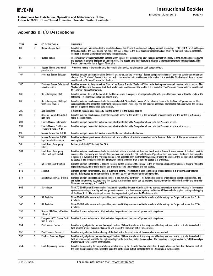
Instructional BookletEffective: June 2015 Page 41
Instructions for Installation, Operation and Maintenance of the Eaton ATC-900 Open/Closed Transition Transfer Switch Controller
Appendix B: I/O Descriptions
TYPE I/O I/O DEFINITIONS SUMMARY
6C I Remote Engine Test Provides an input to initiate a test to simulate a loss of the Source 1 as standard. All programmed time delays (TDNE, TDEN, etc.) will be per-formed as part of the test. Engine run ime of the test is equal to the plant exerciser programmed set point. All tests are fail-safe protected. The test is initiated via remote momentary contact closure.
8E I Bypass Timers The Time Delay Bypass Pushbutton contact, when closed, will reduce any or all of the programmed time delay to zero. Must be executed when the appropriate timer is displayed on the controller. The bypass time delay feature is initiated via remote momentary contact closure. (The front of the controller has a Bypass Timer also).
8F I Bypass Timers w external push button
Provides a means to bypass the time delays with via a device panel mounted push-button switch.
10A I Preferred Source Selector Provides a means to designate either Source 1 or Source 2 as the “Preferred” Source using a remote contact or device panel mounted contact closure. The “Preferred” Source is the source that the transfer switch will connect the load to if it is available. The Preferred Source setpoint must be set to "External" to use this feature.
10C I Preferred Source Selector w/selector switch
Provides a means to designate either Source 1 or Source 2 as the “Preferred” Source via device panel mounted selector switch control. The “Preferred” Source is the source that the transfer switch will connect the load to if it is available. The Preferred Source setpoint must be set to "External" to use this feature.
26D I Go to Emergency (S2) Provides a means to send the switch to the Non-preferred (Emergency) sourceproviding the voltage and frequency are within the limits of the setpoints. This signal will initiate an engine start.
26E I Go to Emergency (S2) Input w/selector Switch
Provides a device panel mounted selector switch labeled, "Auto/Go to Source 2", to initiate a transfer to the Source 2 power source. This includes starting the generator, performing the programmed time delays and the transfer operation. Re-transfer will occur when the external contact is opened. This is a fail-safe function.
29E I ATS in Bypass A signal to the controller to specify that the switch is in the bypass position
29G I Selector Switch for Auto & Non-Auto
Provides a device panel mounted selector switch to specify if the switch is in the automaitc or normal mode or if the switch is in Non-auto-matic electrical mode.
29K I Enable Manual Retrtansfer Provides an input to remotely initiate a manual retransfer from the Non-preferred source to the Preferred source.
29J I Enable Manual Pushbutton Transfer E to N or N to E
Provides an input to remotely initiate a manual retransfer from the Non-preferred source to the Preferred source or vice-versa.
29L I Manual Retransfer On/Off Provides an input to remotely enable or disable the manual retransfer feature.
29M I Manual Retransfer On/Off Input w/selector switch
Provides an device panel mounted selector switch to enable or disable the manual retransfer feature. Selection of this option automatically adds option 29J.
36 I Load Shed - Emergency Inhibit
Enables load shed (S2 Inhibit), See 36A
36A I Load Shed - Emergency Inhibit w Keyed Switch
Provides a device panel mounted selector switch to initiate a load circuit disconnection from the Source 2 power source. If the load circuit is connected to Emergency and the selector switch is switches to the "S2 Inhibit/Enabled" position, then a re-transfer to Source 1 is completed if Source 1 is available. If the Preferred Source is not available, then the transfer switch will transfer to neutral. If the load circuit is connected to Source 1 and the switch is in the "Emergency Inhibit" position, then a transfer Source 2 is prohibited.
37 I Go to "Isolated" Position Provides an input to transfer a 3 position transfer switch (source 1/off/source 2) to the off position using a remote contact closure. When the signal is removed, the transfer switch will transfer back to the available, prefrred source.
81J I Lockout Provides an input to temporarily disable automatic control. This feature is used to indicate a tripped breaker in a breaker based transfer switch. It is treated as an alarm and the alarm must be rest to continue automatic operation.
81K I Monitor Mode (N.O. or N.C.) Provides an input to disable automatic control in the ATC-900 controller. This function is used for when manual operation is required. The controller continues to accurately monitor source status and set points can be changed, however no action will be inititated by the controller. There are two settings, N.O. and N.C.
90B I Slave Input The ATC-900 Master/Slave controller functionality provides the user with the ability to use two independent transfer switches in three source systems consisting of a utility and two generator sources. In a three-source system, the Master ATS controls the engine starting and stopping of the Slave ATS. The slave input receives the engine start signal from the Master controller.
14C O S1 Available The ATC-900 will measure voltage and frequency and if they are measured in the envelope of the settings an Output will show that S1 is Available
14D O S2 Available The ATC-900 will measure voltage and frequency and if they are measured in the envelope of the settings an Output will show that S2 is Available
15R O Normal (S1) Source Position 1 Form C
Provides 1 form-c relay contact that indicates the position of the source 1 power switching device.
15S O Emergency (S2) Source Posi-tion 1 Form C
Provides 1 form-c relay contact that indicates the position of the source 2 power switching device.
35A O Pre-Transfer Contacts Provides a signal prior to the transferring of the load. Will not transfer until the programmable delay set point in the controller is reached. If both sources are not available, this option will ignore the time delay set in the controller.
35D O Post Transfer Contacts Provides a signal after the transferring of the load to the delay set point of the controller when reached.
35C O Pre/Post Transfer Signal Provides a signal prior to the transferring of the load. Will not transfer until the programmable delay set point in the controller is reached. If both sources are not available, this option will ignore the time delay set in the controller. The time delay is programmable for 0-120 second pre transfer and 0-120 seconds post transfer.
45A-L O Load Sequencing Contacts Provides the capability for sequential contact closure of up to 10 contacts after a transfer. A single adjustable time delay between each of the relay closures is provided. Operates using the configurable output contacts (form-c). Adjustable 0-120 seconds.
IB140012EN For more information visit: www.eaton.com
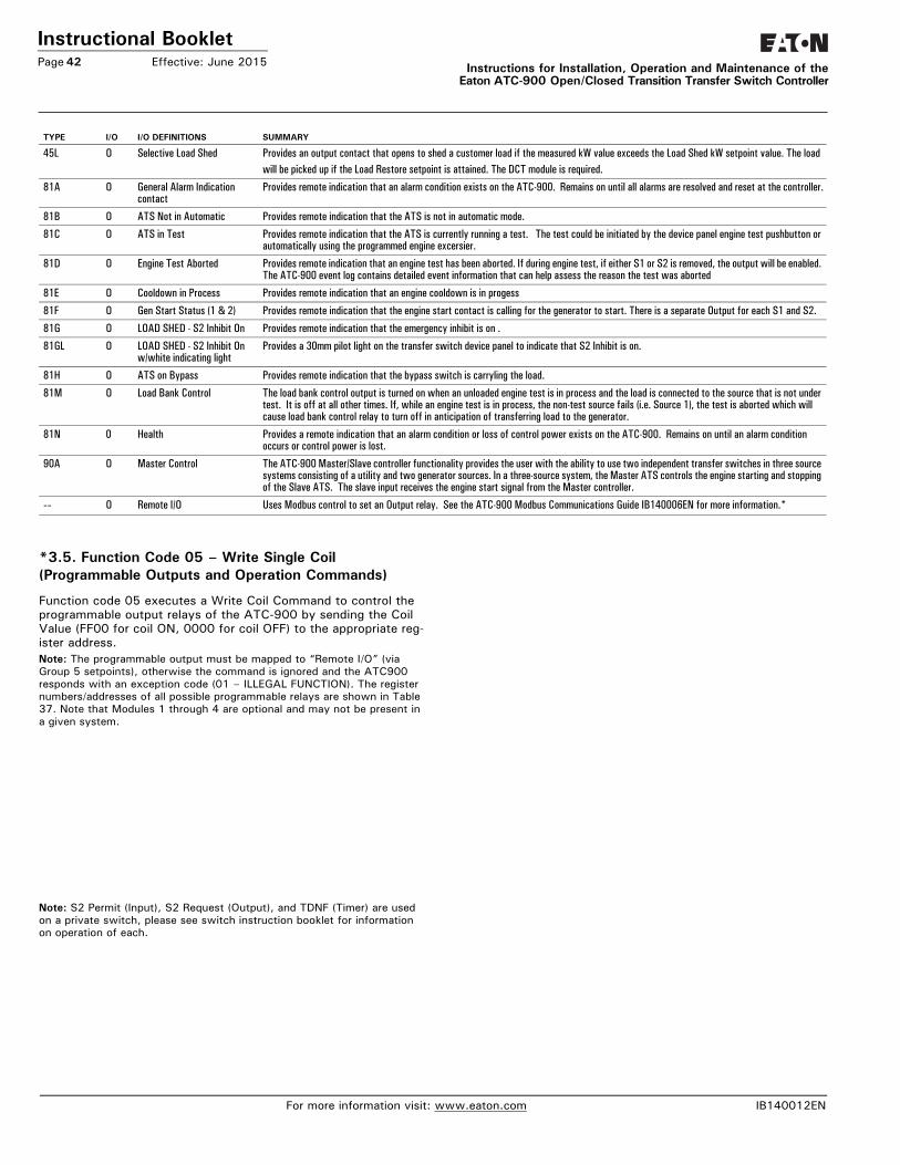
Instructional BookletPage 42 Effective: June 2015 Instructions for Installation, Operation and Maintenance of the
Eaton ATC-900 Open/Closed Transition Transfer Switch Controller
*3.5. Function Code 05 – Write Single Coil (Programmable Outputs and Operation Commands)
Function code 05 executes a Write Coil Command to control the programmable output relays of the ATC-900 by sending the Coil Value (FF00 for coil ON, 0000 for coil OFF) to the appropriate reg-ister address. Note: The programmable output must be mapped to “Remote I/O” (via Group 5 setpoints), otherwise the command is ignored and the ATC900 responds with an exception code (01 – ILLEGAL FUNCTION). The register numbers/addresses of all possible programmable relays are shown in Table 37. Note that Modules 1 through 4 are optional and may not be present in a given system.
Note: S2 Permit (Input), S2 Request (Output), and TDNF (Timer) are used on a private switch, please see switch instruction booklet for information on operation of each.
45L O Selective Load Shed Provides an output contact that opens to shed a customer load if the measured kW value exceeds the Load Shed kW setpoint value. The loadwill be picked up if the Load Restore setpoint is attained. The DCT module is required.
81A O General Alarm Indication contact
Provides remote indication that an alarm condition exists on the ATC-900. Remains on until all alarms are resolved and reset at the controller.
81B O ATS Not in Automatic Provides remote indication that the ATS is not in automatic mode.
81C O ATS in Test Provides remote indication that the ATS is currently running a test. The test could be initiated by the device panel engine test pushbutton or automatically using the programmed engine excersier.
81D O Engine Test Aborted Provides remote indication that an engine test has been aborted. If during engine test, if either S1 or S2 is removed, the output will be enabled. The ATC-900 event log contains detailed event information that can help assess the reason the test was aborted
81E O Cooldown in Process Provides remote indication that an engine cooldown is in progess
81F O Gen Start Status (1 & 2) Provides remote indication that the engine start contact is calling for the generator to start. There is a separate Output for each S1 and S2.
81G O LOAD SHED - S2 Inhibit On Provides remote indication that the emergency inhibit is on .
81GL O LOAD SHED - S2 Inhibit On w/white indicating light
Provides a 30mm pilot light on the transfer switch device panel to indicate that S2 Inhibit is on.
81H O ATS on Bypass Provides remote indication that the bypass switch is carryling the load.
81M O Load Bank Control The load bank control output is turned on when an unloaded engine test is in process and the load is connected to the source that is not under test. It is off at all other times. If, while an engine test is in process, the non-test source fails (i.e. Source 1), the test is aborted which will cause load bank control relay to turn off in anticipation of transferring load to the generator.
81N 0 Health Provides a remote indication that an alarm condition or loss of control power exists on the ATC-900. Remains on until an alarm condition occurs or control power is lost.
90A O Master Control The ATC-900 Master/Slave controller functionality provides the user with the ability to use two independent transfer switches in three source systems consisting of a utility and two generator sources. In a three-source system, the Master ATS controls the engine starting and stopping of the Slave ATS. The slave input receives the engine start signal from the Master controller.
-- O Remote I/O Uses Modbus control to set an Output relay. See the ATC-900 Modbus Communications Guide IB140006EN for more information.*
TYPE I/O I/O DEFINITIONS SUMMARY
For more information visit: www.eaton.com IB140012EN
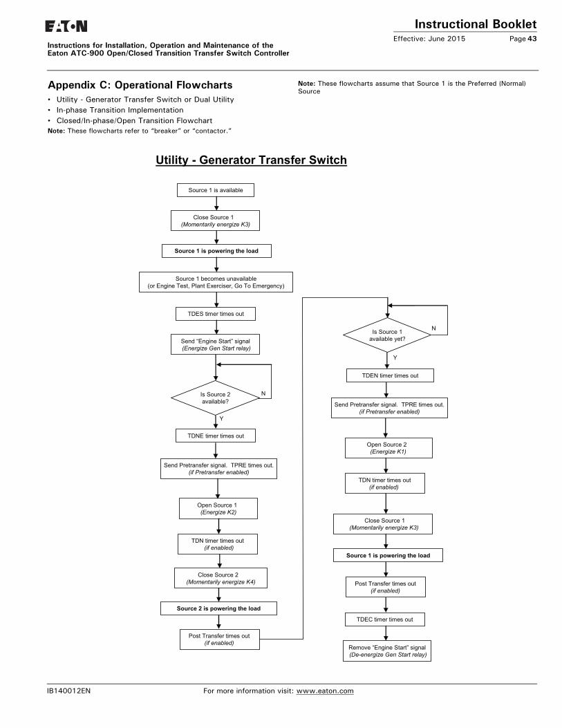
Instructional BookletEffective: June 2015 Page 43
Instructions for Installation, Operation and Maintenance of the Eaton ATC-900 Open/Closed Transition Transfer Switch Controller
Appendix C: Operational Flowcharts• Utility - Generator Transfer Switch or Dual Utility • In-phase Transition Implementation• Closed/In-phase/Open Transition FlowchartNote: These flowcharts refer to “breaker” or “contactor.”
Note: These flowcharts assume that Source 1 is the Preferred (Normal) Source
Source 1 is available
Is Source 2 available?
Close Source 2 (Momentarily energize K4)
N
Utility - Generator Transfer Switch
Close Source 1 (Momentarily energize K3)
Source 1 becomes unavailable(or Engine Test, Plant Exerciser, Go To Emergency)
TDES timer times out
Send “Engine Start” signal (Energize Gen Start relay)
TDNE timer times out
Open Source 1 (Energize K2)
Y
Source 2 is powering the load
TDEN timer times out
Open Source 2 (Energize K1)
Close Source 1 (Momentarily energize K3)
NIs Source 1 available yet?
Y
Source 1 is powering the load
TDN timer times out(if enabled)
TDN timer times out(if enabled)
Source 1 is powering the load
TDEC timer times out
Remove “Engine Start” signal (De-energize Gen Start relay)
Send Pretransfer signal. TPRE times out. (if Pretransfer enabled)
Send Pretransfer signal. TPRE times out. (if Pretransfer enabled)
Post Transfer times out(if enabled)
Post Transfer times out(if enabled)
IB140012EN For more information visit: www.eaton.com
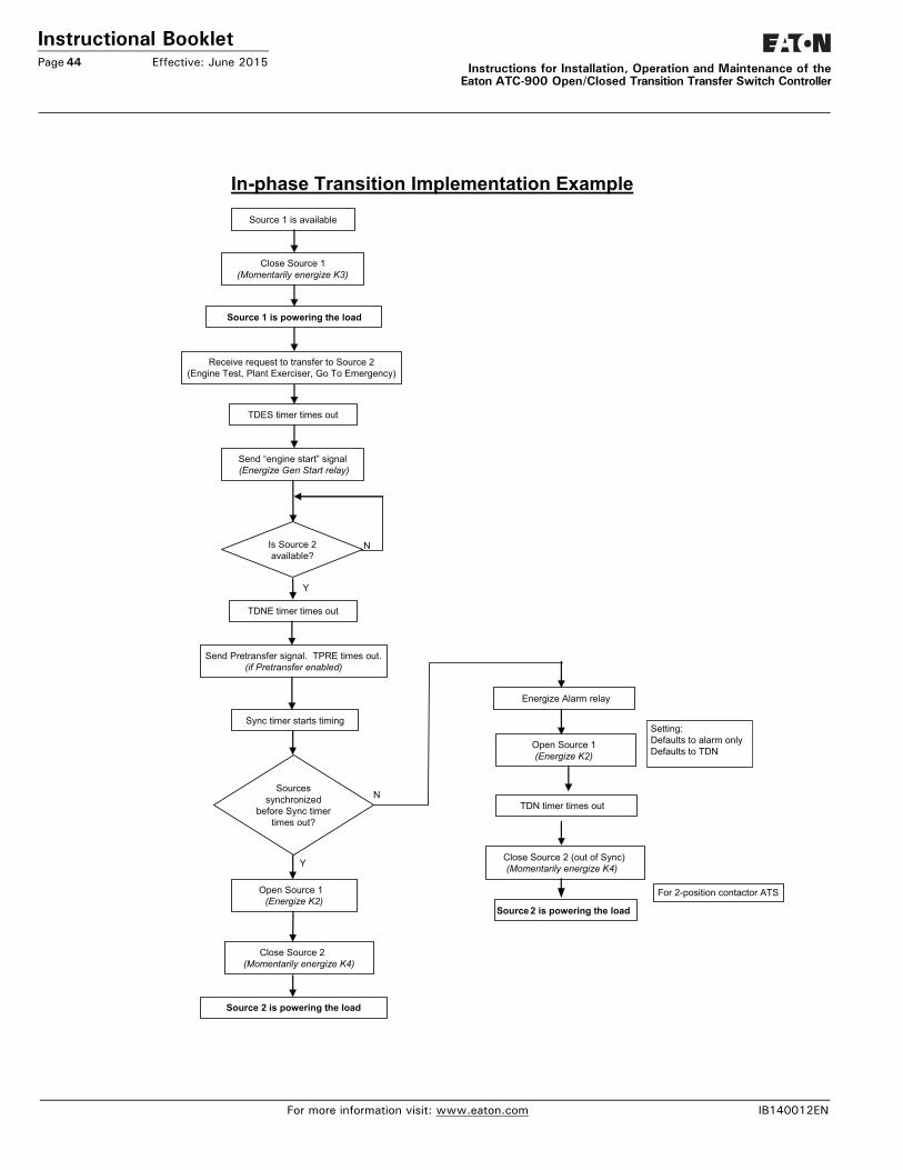
Instructional BookletPage 44 Effective: June 2015 Instructions for Installation, Operation and Maintenance of the
Eaton ATC-900 Open/Closed Transition Transfer Switch Controller
Source 1 is available
Is Source 2 available?
N
In-phase Transition Implementation Example
Close Source 1 (Momentarily energize K3)
Receive request to transfer to Source 2(Engine Test, Plant Exerciser, Go To Emergency)
TDES timer times out
Send “engine start” signal (Energize Gen Start relay)
TDNE timer times out
Y
Source 2 is powering the load
Energize Alarm relay
Open Source 1 (Energize K2)
Close Source 2 (out of Sync)(Momentarily energize K4)
Source 1 is powering the load
TDN timer times out
Source 2 is powering the load
Sources synchronized
before Sync timer times out?
Sync timer starts timing
Open Source 1 (Energize K2)
Close Source 2 (Momentarily energize K4)
Y
N
Send Pretransfer signal. TPRE times out. (if Pretransfer enabled)
For 2-position contactor ATS
Setting:Defaults to alarm onlyDefaults to TDN
For more information visit: www.eaton.com IB140012EN
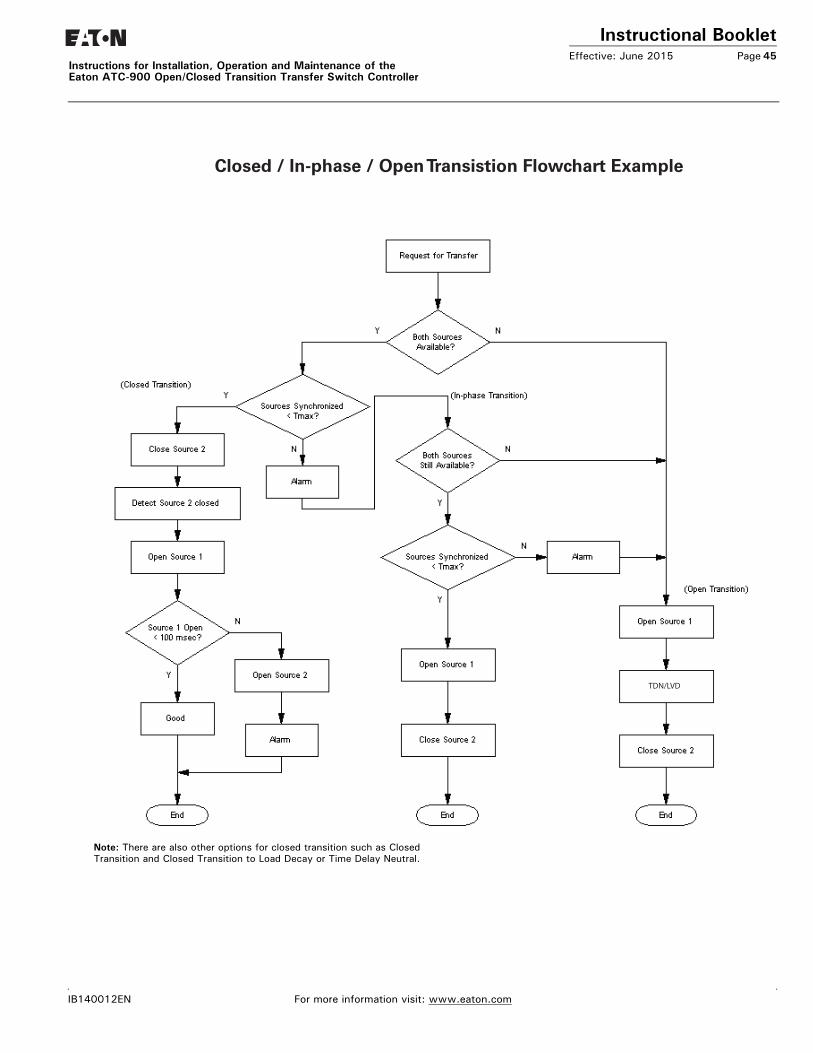
Instructional BookletEffective: June 2015 Page 45
Instructions for Installation, Operation and Maintenance of the Eaton ATC-900 Open/Closed Transition Transfer Switch Controller
This instruction booklet is published solely for information purposes and should not be considered all-inclusive. If further information is required, you should consult an authorized Eaton sales representative.
The sale of the product shown in this literature is subject to the terms and conditions outlined in appropriate Eaton selling policies or other contractual agreement between the parties. This literature is not intended to and does not enlarge or add to any such contract. The sole source governing the rights and remedies of any purchaser of this equipment is the contract between the purchaser and Eaton.
NO WARRANTIES, EXPRESSED OR IMPLIED, INCLUDING WARRANTIES OF FITNESS FOR A PARTICULAR PURPOSE OR MERCHANT-ABILITY, OR WARRANTIES ARISING FROM COURSE OF DEALING OR USAGE OF TRADE, ARE MADE REGARDING THE INFORMA-TION, RECOMMENDATIONS, AND DESCRIPTIONS CONTAINED HEREIN. In no event will Eaton be responsible to the purchaser or user in contract, in tort (including negligence), strict liability or otherwise for any special, indirect, incidental or consequential damage or loss whatsoever, including but not limited to damage or loss of use of equipment, plant or power system, cost of capital, loss of power, additional expenses in the use of existing power facilities, or claims against the purchaser or user by its customers resulting from the use of the information, recommendations and description contained herein.
CSA is a registered trademark of the Canadian Standards Association. National Electrical Code and NEC are registered trademarks of the National Fire Protection Association, Quincy, Mass. NEMA is the registered trademark and service mark of the National Electrical Manufacturers Association. Uniform Building Code (UBC) is a trademark of the International Conference of Building Officials (ICBO). UL is a federally registered trademark of Underwriters Laboratories Inc.
Closed / In-phase / Open Transistion Flowchart Example
TDN/LVD
Note: There are also other options for closed transition such as Closed Transition and Closed Transition to Load Decay or Time Delay Neutral.
IB140012EN For more information visit: www.eaton.com

Instructional BookletPage 46 Effective: June 2015
Instructions for Installation, Operation and Maintenance of theEaton ATC-900 Open/Closed Transition Transfer Switch Controller
Notes:
For more information visit: www.eaton.com IB140012EN

Instructional BookletEffective: June 2015 Page 47
Instructions for Installation, Operation and Maintenance of the Eaton ATC-900 Open/Closed Transition Transfer Switch Controller
Notes:
IB140012EN For more information visit: www.eaton.com
Instructional BookletPage 48 Effective: June 2015
Instructions for Installation, Operation and Maintenance of theEaton ATC-900 Open/Closed Transition Transfer Switch Controller
This instruction booklet is published solely for information pur-poses and should not be considered all-inclusive. If further infor-mation is required, you should consult an authorized Eaton sales representative.
The sale of the product shown in this literature is subject to the terms and conditions outlined in appropriate Eaton selling policies or other contractual agreement between the parties. This litera-ture is not intended to and does not enlarge or add to any such contract. The sole source governing the rights and remedies of any purchaser of this equipment is the contract between the pur-chaser and Eaton.
NO WARRANTIES, EXPRESSED OR IMPLIED, INCLUDING WAR-RANTIES OF FITNESS FOR A PARTICULAR PURPOSE OR MER-CHANTABILITY, OR WARRANTIES ARISING FROM COURSE OF DEALING OR USAGE OF TRADE, ARE MADE REGARDING THE INFORMATION, RECOMMENDATIONS, AND DESCRIPTIONS CONTAINED HEREIN. In no event will Eaton be responsible to the purchaser or user in contract, in tort (including negligence), strict liability or otherwise for any special, indirect, incidental or conse-quential damage or loss whatsoever, including but not limited to damage or loss of use of equipment, plant or power system, cost of capital, loss of power, additional expenses in the use of exist-ing power facilities, or claims against the purchaser or user by its customers resulting from the use of the information, recommen-dations and description contained herein.
CSA is a registered trademark of the Canadian Standards Associa-tion. National Electrical Code and NEC are registered trademarks of the National Fire Protection Association, Quincy, Mass. NEMA is the registered trademark and service mark of the National Elec-trical Manufacturers Association. Uniform Building Code (UBC) is a trademark of the International Conference of Building Officials (ICBO). UL is a federally registered trademark of Underwriters Lab-oratories Inc.
June 2015
© 2015 Eaton All Rights ReservedPrinted in USAPublication No. IB140012EN/TBG1123
EatonElectrical Sector1000 Eaton BoulevardCleveland, OH 44122United StatesFor Transfer Switches:877-ETN CARE (877-366-2273)option 2, option 4, and then option 3Eaton.com