instructions: 12 vdc, single acting (power up / gravity down) unit
TRANSCRIPT
3195 D Airport Loop
Costa Mesa, CA 92626
Tel. 714.556.8818 Fax 714.556.1520
w w w . k t i h y d r a u l i c s i n c . c o m
1
Instructions: 12 vdc, Single Acting (Power UP / Gravity DOWN) Unit
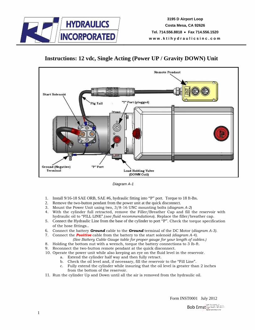
Diagram A-1
1. Install 9/16-18 SAE ORB, SAE #6, hydraulic fitting into “P” port. Torque to 18 ft-lbs. 2. Remove the two-button pendant from the power unit at the quick disconnect. 3. Mount the Power Unit using two, 3/8-16 UNC mounting bolts (diagram A-2) 4. With the cylinder full retracted, remove the Filler/Breather Cap and fill the reservoir with
hydraulic oil to “FILL LINE”.(see fluid recommendations). Replace the filler/breather cap. 5. Connect the Hydraulic Line from the base of the cylinder to port “P”. Check the torque specification
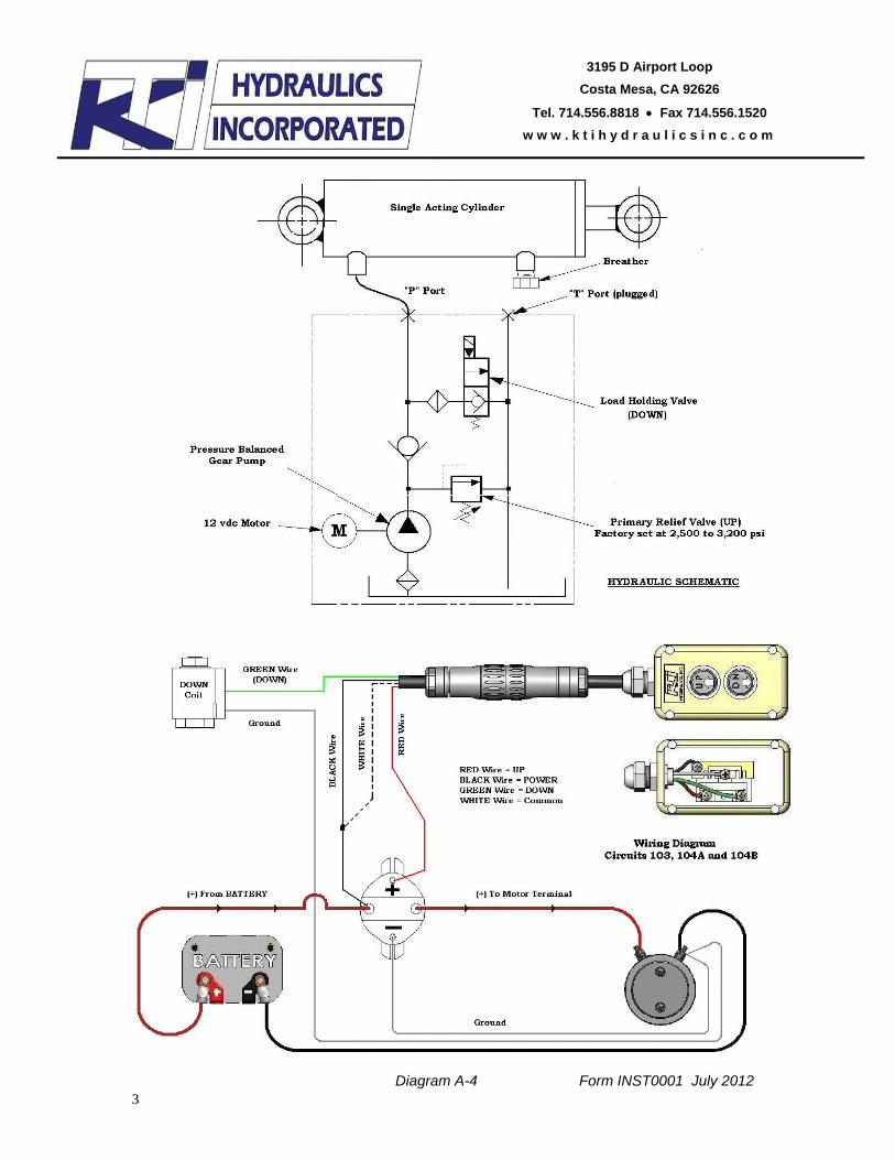
of the hose fittings.. 6. Connect the battery Ground cable to the Ground terminal of the DC Motor (diagram A-3). 7. Connect the Positive cable from the battery to the start solenoid (diagram A-4).
(See Battery Cable Gauge table for proper gauge for your length of cables.) 8. Holding the bottom nut with a wrench, torque the battery connections to 3 lb-ft. 9. Reconnect the two-button remote pendant at the quick disconnect. 10. Operate the power unit while also keeping an eye on the fluid level in the reservoir.
a. Extend the cylinder half way and then fully retract. b. Check the oil level and, if necessary, fill the reservoir to the “Fill Line”. c. Fully extend the cylinder while insuring that the oil level is greater than 2 inches
from the bottom of the reservoir. 11. Run the cylinder Up and Down until all the air is removed from the hydraulic oil.
Form INST0001 July 2012

3195 D Airport Loop
Costa Mesa, CA 92626
Tel. 714.556.8818 Fax 714.556.1520
w w w . k t i h y d r a u l i c s i n c . c o m
2
Form INST0001 July 2012
Diagram A-2 Diagram A-3
Fluid Recommendations KTI recommends using a premium hydraulic oil to ensure optimum performance and system life. Select oil that has anti-wear properties, rust and oxidation inhibitors, foam inhibitors and good stability. Examples of premium grade hydraulic oils: Chevron Rando HDZ, Mobil DTE 10, DTE 20 series, AMSOIL, and Shell Tellus. Automotive Transmission Oils are acceptable under normal conditions. Aviation Oils such as Valvoline ROYCO series or Mobil Aero HF or HFA may be used in prolonged, extreme cold environments. Do Not Use Biodegradable Hydraulic Fluid. Do Not Mix Oils.
Ambient Temperature Range ISO Viscosity Grade - 20F to + 32F 15 (- 29C to + 0C)
+ 14F to + 120F 22, 32, ATF (- 10C to + 49C)
Battery Cables To minimize voltage drop, increase the gauge size of the battery cables as the length of the positive and ground cables increase. Low voltage will cause the motor to run at higher amps and may cause damage to other electrical components. .
Cable Length Wire Gauge Nominal OD (in.) 1 to 2 feet 4 gauge 0.43 3 to 4 feet 2 gauge 0.49 5 to 7 feet 1 gauge 0.56 8 to 9 feet 1/0 gauge 0.61
10 to 12 feet 2/0 gauge 0.66 13 to 15 feet 3/0 gauge 0.72 16 to 19 feet 4/0 gauge 0.78
3195 D Airport Loop
Costa Mesa, CA 92626
Tel. 714.556.8818 Fax 714.556.1520
w w w . k t i h y d r a u l i c s i n c . c o m
3
Diagram A-4 Form INST0001 July 2012