instruction manuald2z4qs2e3spnc1.cloudfront.net/product_file/file/1438/...6 safety information 1.2...
TRANSCRIPT

Instruction manual
Kleen Sweep 25W (625821)

2
IntroductionPrefaceDear customer,We hope that the excellent qualities of the machine justify the faith you have shown in us by purchasing the product.In order to ensure that you can work with the machine safely, please read the chapter on safety before running the machine for the first time.Your safety, and that of others, is de-pendent on your ability to control the machine. Therefore, read the operating manual thoroughly before operating the machine for the first time. The operating manual contains all the important information you need to oper-ate, maintain and service the machine. Sections of this operating manual which are relevant to safety are marked by the hazard label.If you have any questions with regard to the machine or operating manual, you can contact your service partner at any time.
We would like to emphasize that no le-gal claims can be asserted in respect of any work described in this manual. Please pay attention that only original spare parts are used for any necessary maintenance and repair work. Only original spare parts can guarantee long, reliable equipment operation. We re-serve the right to make technical im-provements.
Valid from: January 2009
Minuteman International Inc.14N845 U.S. Route 20PINGREE GROVE, II. 60140-8893U.S.A.
Intended useThe Kleen Sweep 25W is a sweeping machine conceived exclusively for sweeping up dry and wet surfaceareas such as production plants, ware-houses, parking lotsand pedestrian walkways. In addition, the Kleen Sweep 25W can also be used to remove dry dirt from carpets. Any use beyond this is regarded as improper use. The manu-facturer is not considered liable for any damage resulting from improper use; the user is solely responsible for all the risks. Intended use also includes main-taining and observing the operating, maintenance and repair conditions pre-scribed by the manufacturer. The Kleen Sweep 25W may only be operated, serviced and repaired by per-sonnel who are familiar with the work in-volved and are aware of the risks. The applicable accident prevention laws must be observed and any generally accepted health and safety directives must be maintained. The manufacturer is not deemed liable for any damage re-sulting from unauthorized modifications to the machine.
Introduction

3
Notes on warrantyThe terms of the sales contract apply. Damages are not subject to warranty if they are due to non-compliance with the maintenance and service provisions. The maintenance work has to be perfor-med by an authorized Minuteman ser-vice center and confirmed in the "Maintenance certificate" which is the warranty document.The following is excluded from warranty: fuses, natural wear, damages caused by overload, inexpert handling and unauthorized modification of the machine. Moreover, any claim for war-ranty cannot be accepted if damages of the machine are caused by fitting parts or accessories without Minuteman's pri-or and explicit consent or by non-com-pliance with the maintenance instructions.
Acceptance of the machineUpon arrival, check machine for possi-ble damages in transit. Follow un-packing instructions on shipping pallet. Each unit has been tested and through-ly inspected before shipment. Any da-mage is the responsibility of the delivery carrier who should be notified immedia-tely.
Minuteman International Inc.14N845 U.S. Route 20PINGREE GROVE, IL. 60140-8893U.S.A.
Introduction

4
Table of content
Introduction . . . . . . . . . . . . . 2Preface. . . . . . . . . . . . . . . . . . 2Intended use . . . . . . . . . . . . . 2Notes on warranty . . . . . . . . . 3Acceptance of the machine . . 3
1 Safety Information . . . . . . . . 51.1 Safety and warning symbols . 51.2 General information . . . . . . . . 61.3 Operating information. . . . . . . 61.4 Maintenance information . . . . 61.5 Particular risks . . . . . . . . . . . . 71.6 Environmental protection . . . . 81.7 Labels on the machine . . . . . . 9
2 Starting Up . . . . . . . . . . . . . 112.1 Unpacking and assembling . 112.2 Instruction. . . . . . . . . . . . . . . 112.3 Initial battery charge. . . . . . . 112.4 Prior to starting up . . . . . . . . 122.5 Operation . . . . . . . . . . . . . . . 122.6 Stopping the machine . . . . . 122.7 After completing work. . . . . . 12
3 Operation . . . . . . . . . . . . . . 133.1 Method of operation . . . . . . . 133.2 Operating and indicator
elements. . . . . . . . . . . . . . . . 143.2.1 Operating panel . . . . . . . . . . 143.2.2 Operating elements on the ma-
chine. . . . . . . . . . . . . . . . . . . 16
4 Technical Data . . . . . . . . . . 18
5 Maintenance and Service . . . . . . . . . . . . . . . . 20
5.1 System maintenance . . . . . 205.2 Proof of Maintenance . . . . . 215.3 Maintenance Plan . . . . . . . . 225.4 Battery system . . . . . . . . . . . 265.4.1 Charging batteries . . . . . . . . 275.4.2 Total discharge signal transduc-
er (TSG) . . . . . . . . . . . . . . . . 275.4.3 Servicing the driving batteries .
275.4.4 Removing the batteries . . . . 275.4.5 Inserting the batteries. . . . . . 275.4.6 Disposing of batteries. . . . . . 275.5 Side brushes . . . . . . . . . . . . 285.5.1 Changing the side brush . . . 295.5.2 Setting the sweeping pattern 295.6 Rotary brush. . . . . . . . . . . . . 305.6.1 Cleaning the brush space . . 315.6.2 Changing the rotary brush . . 31
5.6.3 Setting the sweeping pattern 315.6.4 Changing the sealing strips . 315.6.5 Changing the timing belt . . . 315.7 Dust vacuum . . . . . . . . . . . . 325.7.1 Cleaning the filter . . . . . . . . . 335.7.2 Changing the filter . . . . . . . . 335.8 Sweepings container . . . . . . 345.8.1 Emptying the sweepings con-
tainer . . . . . . . . . . . . . . . . . . 355.8.2 Changing the seal . . . . . . . . 35
EC-Declaration of Conformity 37
5
Safety Information
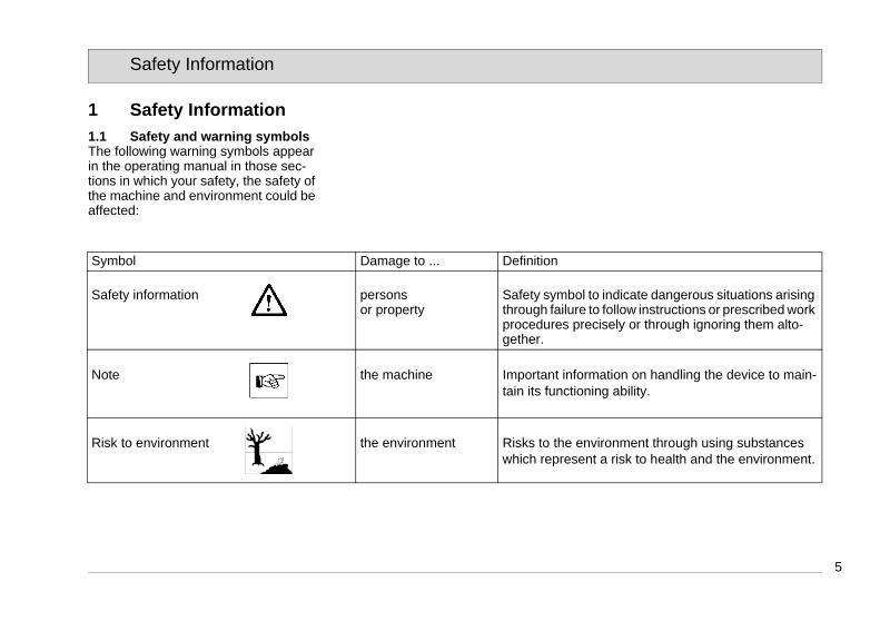
1 Safety Information1.1 Safety and warning symbols The following warning symbols appear in the operating manual in those sec-tions in which your safety, the safety of the machine and environment could be affected:
Symbol Damage to ... Definition
Safety information persons or property
Safety symbol to indicate dangerous situations arising through failure to follow instructions or prescribed work procedures precisely or through ignoring them alto-gether.
Note the machine Important information on handling the device to main-tain its functioning ability.
Risk to environment the environment Risks to the environment through using substances which represent a risk to health and the environment.

6
Safety Information
1.2 General information• In addition to the information provid-
ed in this operating manual, all the legally applicable health and safety provisions must be observed.
• Before starting up the machine for the first time, read the operating manual supplied with it thoroughly as well as any separate manuals pro-vided with additional or attachment devices and observe all the informa-tion during work.
• The equipment may only be operat-ed, serviced and repaired by person-nel trained by Minuteman technical experts.
• Particular attention should be paid to the information regarding safety. Technical expertise is the key to pre-venting errors when operating the machine and ensuring trouble-free operation.
• The operating manual must always be kept at the operating location of the machine and, as a result, should kept in a safe place on the equip-ment.
• If the equipment is sold or rented out, these documents should be trans-ferred to the new owner/operator.
The transfer should be confirmed!• The warning labels attached to the
machine provided important informa-tion concerning safe operation. Illeg-ible or missing labels must be replaced by new ones.
• For reasons of safety, always use original spare parts.
1.3 Operating information• Before starting the machine up for
the first time, the battery to be used must be fully charged, properly, by implementing the initial battery charge routine. Please pay attention to the operating manual provided with the charging unit as well as the manual from the battery manufactur-er. Minuteman assumes no liability for damage to the battery caused by a fault when the battery is charged for the first time.
• Check the operational safety of the machine each time before starting it up! Clear any faults immediately!
• Before starting work, the operator must be fully familiar with all adjust-ment, operating and control ele-ments as well as their respective function! It is too late to do this when
the machine is actually in operation!• Always wear heavy duty, non-slip
footwear when working with the ma-chine.
• The machine may only be used on those surfaces which have been ap-proved by the contractor or person appointed by him.
• When using the machine, it is essen-tial to pay attention to third parties, especially children.
• Accelerate the machine immediately after switching on the brush head drive, otherwise imprints of the brush could be produced on the floor.
• The machine is not suitable for clear-ing up hazardous, flammable or explosive fluids, dust or substances.
• It is forbidden to use the machine in potentially explosive atmospheres.
• The side brush must be raised in or-der to transport the machine.
• The machine has been conceived for use on level surfaces with a maxi-mum gradient of 2%.
1.4 Maintenance information• Operating personnel must complete
the necessary daily and weekly maintenance work. All other mainte-

7
Safety Information
nance work must be completed at your local Minuteman service center.
• The maintenance work and mainte-nance intervals prescribed in the op-erating manual must be adhered to.
• Suitable tools must be used for cleaning and maintenance work.
• The machine must be inspected by a recognized technical expert in re-spect of operational safety, within the terms of the applicable accident prevention laws, at reasonable inter-vals (we recommend at least once a year) and following modification or repairs .
• Spare parts must comply with the minimum technical requirements stipulated by the manufacturer! This is ensured by the use of original spare parts.
• The machine must be switched off prior to cleaning or servicing it or to replacing parts. The drive bar must be out of operation!
• Always disconnect the battery plug before starting any work on the elec-trical installation.
• When working in the area of the raised hood, it must be hinged open fully to prevent it being knocked shut
or further open and down uninten-tionally.
• It is not permitted to clean the ma-chine with a pressure washer or steam blaster.
• It is not permitted to use aggressive and corrosive cleaning agents.
• Allow the machine to dry after being cleaned, e.g. over the weekend.
• Only start the machine up when all the safety equipment has been in-stalled and brought to its protecting position.
1.5 Particular risksElectronics• In the case of defects in the electrical
installation, switch the machine off immediately and clear the fault.
• Work on the electrical equipment may only be carried out by electri-cians who have received the neces-sary training and in accordance with the electrical engineering regula-tions.
• The machine's electrical equipment must be inspected/checked at regu-lar intervals. Defects, such as loose connections and cable damage, must be rectified immediately.
Batteries• Observe the information in the oper-
ating manual provided by the battery manufacturer.
• It is possible that sparking will occur when connecting the batteries.
• Batteries may only be handled and changed by properly skilled mainte-nance personnel.
• The machine has been set up for op-eration using maintenance-free bat-teries. If other battery types are used, the machine must be set up for use with them by an authorized Minuteman service center.
• Never lay any metallic objects or tools on batteries - risk of short cir-cuit!
• For further safety information, refer to supplementary sheet 88-60-2556 - notes on driving batteries.
8
Safety Information
1.6 Environmental protection• A certain factual expertise is re-
quired in order to use substances which could represent a risk to health and the environment.
• Observe the applicable laws and lo-cal regulations when disposing of waste.
• Used batteries with the recycling symbol contain reusable commodi-ties. In accordance with symbol with the crossed out bin, these batteries must not be disposed of in domestic waste. The return and recycling of batteries must be agreed on withMinuteman authorized dealers in accor-dance with § 8 BattV (Battery Directive)!

9
Safety Information
1.7 Labels on the machineThe following safety and warning labels are attached to the machine where eas-ily legible. Missing or illegible labels must be replaced immediately.
Company logo (Fig. 1/1)
Rating plate (Fig. 1/2)
Filter shaker (Fig. 1/3)
Read and observe the operating manual (Fig. 1/4)
Maximum permissible gradient (Fig. 1/5)
Wear compensator for side brush (Fig. 1/6)
Wear compensator for rotary brush (Fig. 1/7)

10
Safety Information
Fig.1
1
7
6
2
4
3
5

11
Starting Up
2 Starting Up2.1 Unpacking and assemblingOpen the box, two people are required to remove the machine from the protec-tive foil and place it on the floor.1. Fix the side brush (Fig. 2/1) to the
axle of the side brush drive using the wing bolt and washer supplied.
2. Loosen the two knurled screws (Fig. 2/2) holding the handle a few revolu-tions until the handle can be raised and positioned. Set the handle to a height comfortable for the user and then tighten the knurled screws.
3. Loosen the locking bolt holding the hood (Fig. 2/3) and pivot the hood open.
4. Fix the disassembled cable lug (Fig. 2/4) to the corresponding battery contact. It is possible that sparking will occur when connecting the bat-teries!
5. Close the hood and lock in place with the bolt.
6. The Kleen Sweep 25W is now ready to operate.
Fig.2
2.2 InstructionInstructions to operators are required before putting the machine into service. Only technicians from your local, autho-rized Minuteman dealer are allowed toprovide initial instruction on how to use the machine. The manufacturing plant noti-fies the dealer immediately after deliv-ering the machine and the dealer will contact you to arrange a date for provid-ing the initial instruction.
2.3 Initial battery charge
Before starting the machine up for the first time, the batteries to be used must be fully charged, properly, by imple-menting the initial battery charge routine. Please pay at-tention to the operating manual provided with the charging unit as well as the manual from the battery manufacturer. Minuteman assumes no liability for dam-age to the battery caused by a fault when the battery is charged for the first time.
4
1
2
3

12
Starting Up
2.4 Prior to starting upCarry out the following checks before starting the machine:1. Check the charge status of the bat-
teries.2. Check the levels of wear on the rota-
ry brush and side brush.3. Check the fill level of the sweepings
container.
2.5 OperationPlease read the Safety Information in Chapter 1. Before switching the ma-chine on, ensure that the drive bar (Fig. 3/3) on the handle has not been actuat-ed. 1. Switch the machine on using the
(Fig. 3/1) button: rotary brush drive, dust vacuum and side brush drive are ready to operate.
2. Lower the side brush to its working position using the lever (Fig. 3/4). When working without the side brush: do not lower the side brush and press the button (Fig. 3/2) for the side brush once. The green control lamp goes out.
3. Actuate the drive bar (Fig. 3/3) on the handle: the machine starts to work.
Start work immediately after actuating the drive bar, other-wise imprints could be pro-duced on the floor. Release the drive bar when driving over thresholds.
Fig.3
2.6 Stopping the machineWhen the drive bar is released, the ro-tary brush drive, dust vacuum and side brush drive switch off automatically.
2.7 After completing work1. Drive to an appropriate maintenance
area.2. Stop the machine. Raise the side
brush to its idle position and switch the machine off.
3. Actuate the filter shaker.4. Empty the sweepings container.5. Check the brush space for accumu-
lations of dirt.6. Check the charge status of the bat-
teries.
It is not permitted to clean the machine with a pressure wash-er or steam blaster.
21
3
4
13
Operation
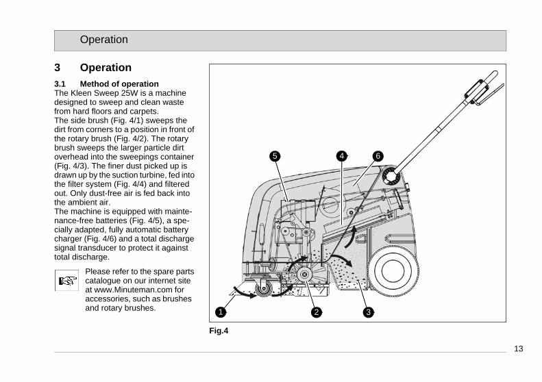
3 Operation3.1 Method of operationThe Kleen Sweep 25W is a machine designed to sweep and clean waste from hard floors and carpets.The side brush (Fig. 4/1) sweeps the dirt from corners to a position in front of the rotary brush (Fig. 4/2). The rotary brush sweeps the larger particle dirt overhead into the sweepings container (Fig. 4/3). The finer dust picked up is drawn up by the suction turbine, fed into the filter system (Fig. 4/4) and filtered out. Only dust-free air is fed back into the ambient air.The machine is equipped with mainte-nance-free batteries (Fig. 4/5), a spe-cially adapted, fully automatic battery charger (Fig. 4/6) and a total discharge signal transducer to protect it against total discharge.
Please refer to the spare parts catalogue on our internet site at www.Minuteman.com for accessories, such as brushes and rotary brushes.
Fig.4
1 2 3
4 65

14
Operation
3.2 Operating and indicator elements
3.2.1 Operating panel1 Control lamp for rotary brush drive,
side brush drive and suction turbine2 ON/OFF button for rotary brush
drive, side brush drive and suction turbine
3 Control lamp for side brush drive4 ON/OFF button for side brush drive5 Control lamp for battery charger
operation6 Charge control indicator7 Drive bar
Fig.5
.
21 3 4 5 6
7

15
Operation
Control lamp for rotary brush drive, side brush drive and suction turbine (Fig. 5/2)The green control lamp indicates that the rotary brush drive and suction tur-bine are ready to operate. If the rotary brush or suction turbine are overloaded, a safety shutdown is triggered and the control lamp flashes.
ON/OFF button for rotary brush, side brush and suction turbine (Fig. 5/1)The button activates the rotary brush drive, side brush drive and suction tur-bine so they are ready to operate. The side brush drive can be switched off separately. The suction turbine can-not be switched off separately which prevents the dust vacuum being activat-ed by accident.
To prevent unauthorized use of the machine, switch the ma-chine off using the button (Fig. 5/1).
Control lamp for side brush drive (Fig. 5/4)The green control lamp indicates that the side brush drive is ready to operate. If the side brush is overloaded, a safety shutdown is triggered and the control lamp flashes.
ON/OFF button for side brush drive (Fig. 5/3)The button can be used to switch off the side brush drive independently of the rotary brush drive and to activate it for use again.
Control lamp for battery charger operation (Fig. 5/5)This control lamp indicates that the bat-teries are being charged.
Charge control indicator (Fig. 5/6)During the charging process, the ma-chine's electronics system controls the machine is not switched on inadvertent-ly and indicates the charge status. The battery charge status is indicated by 4 green and 1 red LED.
The battery voltage is depicted in 5 lev-els:> 25.1 V = all green LEDs on> 24.5 V = bottom 3 green LEDs on> 23.9 V = bottom 2 green LEDs on> 22.7 V = bottom green LED on< 22.7 V = red battery LED flashes
Drive bar (Fig. 5/7)The drive bar switches all the drives which are ready to operate on or off. The drive bar serves to prevent dam-age. If the drive bar is released during operation, all the drives are switched off.

16
Operation
3.2.2 Operating elements on the machine
1 Knurled screws for the handle2 Shaking device lever 3 Sweepings container lock4 Side brush lever5 Charger cable flap
Fig.6
1
2
3
4
5
1
17
Operation
Knurled screws for handle (Fig. 6/1)The two knurled screws enable the han-dle to be adjusted to a comfortable height for the user.
Shaking device lever (Fig. 6/2)In order to clean the filter in the dust vacuum, switch the shaking device le-ver several times quickly to the left and right.
Sweepings container lock (Fig. 6/3)Pull the lock lever up in order to remove the sweepings container.
Side brush lever (Fig. 6/4)Use the lever to lower or raise the side brush.
Charger cable flap (Fig. 6/5)The battery charger cable is located be-hind the flap to the right beside the op-erating panel. Pull the lock downwards to open the flap.

18
Technical Data
4 Technical DataMachine length cm 80
Machine height (handle folded) cm 60
Machine width cm 70Working width cm 60
Load capacity, sweeper's container kg 25
Rotary brush width cm 40Rotary brush diameter cm 19
Area coverage, theoretic m²/h 2400
Sweeper's container volume Liter 40Filter surface m² 1,2
Nominal voltage V 24
Power consumption, rotary brush drive W 210Power consumption, side brush drive W 48
Power consumption, suction turbine drive W 60
Weight without batteries kg 36Weight with batteries kg 51

19
Technical Data
Noise emission value
Sound power level (LwA) measured according to DIN EN 60335-2-72under maximum working conditions: dB (A) 62The sound pressure level (LpA) (at the ear of the operator) measured according to DIN IEC 60335-2-72 under normal working conditions: dB (A) 78Measurement inaccuracy (KpA): dB (A) 2
Vibration
The weighted effective value of acceleration, measured in accordance with DIN EN ISO 5349, to which the upper parts of the body (hand-arm) are exposed under normal working conditions: m/s² < 2.5

20
Maintenance and Service
5 Maintenance and Service
General informationIt is essential to pay attention to the information in Chapter "Safety Information" before completing any service or maintenance work!
By adhering to the maintenance work recommended by us, you can be sure that the machine is always ready to be put into operation.Maintenance and repair work neces-sary on a daily and weekly basis can be carried out by an operator trained to complete the work, all other Minutemansystem maintenance may only be com-pleted by personnel who are correspondingly qualified and trained. Please contact your nearest Minutemanservice center or Minuteman authorized dealer. Failure to observe this annuls any rights to claims under the terms of guarantee in respect of resulting damageor consequential damage.Always specify the serial number in the case of inquiries and spare parts or-ders, refer to section 1.7 - Rating plate.
5.1 Minuteman system maintenanceThe Minuteman system maintenance:• ensures that the Minuteman machine
is always ready for operation (pre- ventive maintenance),
• minimizes operating costs, mainte-nance and repair costs,
• ensures the machine has a long ser-vice life.
Minuteman system maintenance providesindividual modules explaining the special technical work to be carried out and prescribes the intervals at which the work should be performed. Parts to be replaced for the individual maintenance tasks are defined and provided in spare parts kits.
Minuteman system maintenance, cus-tomerWork to be carried out by the customer according to the service and mainte-nance instructions in the operating manual (daily and weekly). The driver/operator receives proper instruction when the machine is delivered.
Minuteman system maintenance I:(every 125 operating hours)Completed by technical experts from an
authorized Minuteman service center inaccordance with the specific machine sys-tem maintenance using spare parts kits.
Minuteman system maintenance II:(every 250 operating hours)Completed by technical experts from an authorized Minuteman service center inaccordance with the specific machine sys-tem maintenance using spare parts kits.
Minuteman system maintenance III/S:(every 500 operating hours, safety check)Completed by technical experts from an authorized Minuteman service center inaccordance with the specific machine sys-tem maintenance using spare parts kits. Completion of all legally prescribed, safety-related tests in accordance with UVV-BGV-TÜV-VDE

21
Maintenance and Service
5.2 Proof of Maintenance
Handover
UpgradingTest driveHandover to customerInstructioncompleted on:
at _________________ operating hours
System Maintenance I125 operating hours
Workshop Stamp
completed on:
at _________________ operating hours
System Maintenance II250 operating hours
Workshop Stamp
completed on:
at _________________ operating hours
System Maintenance I375 operating hours
Workshop Stamp
completed on:
at _________________ operating hours
System Maintenance III/S
500 operating hoursWorkshop Stamp
completed on:
at _________________ operating hours
System Maintenance I625 operating hours
Workshop Stamp
completed on:
at _________________ operating hours
System Maintenance II750 operating hours
Workshop Stamp
completed on:
at _________________ operating hours
System Maintenance I875 operating hours
Workshop Stamp
completed on:
at _________________ operating hours
System Maintenance III/S
1000 operating hoursWorkshop Stamp
completed on:
at _________________ operating hours
System Maintenance I1125 operating hours
Workshop Stamp
completed on:
at _________________ operating hours
System Maintenance II1250 operating hours
Workshop Stamp
completed on:
at _________________ operating hours
System Maintenance I1375 operating hours
Workshop Stamp
completed on:
at _________________ operating hours

22
Maintenance and Service
5.3 Maintenance PlanMinuteman routine maintenanceThe following maintenance work mustbe completed by the customer at the in- tervals stipulated.
ActivityInterval
Daily Weekly
Check the battery charge; recharge if necessary o
Empty the sweeper's container o
Clean the brush space o
Check the filter in the dust vacuum; clean, if necessary o
Check the rotary brush and side brush; clean, if necessary o
Check the sweeping pattern; readjust, if necessary o
Check the sealing strips on the rotary brush for signs of wear; clean, if necessary o
Check the gasket on the sweeper's container o
Check the function of the suction turbine o
Check the sweeper's container lock o
Test drive and function test o
23
Maintenance and Service
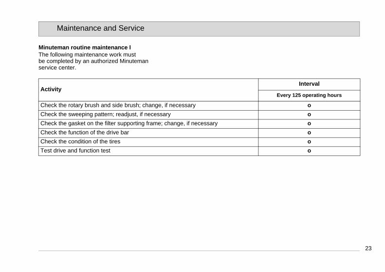
Minuteman routine maintenance IThe following maintenance work must be completed by an authorized Minutemanservice center.
ActivityInterval
Every 125 operating hours
Check the rotary brush and side brush; change, if necessary o
Check the sweeping pattern; readjust, if necessary o
Check the gasket on the filter supporting frame; change, if necessary o
Check the function of the drive bar o
Check the condition of the tires o
Test drive and function test o

24
Maintenance and Service
Minuteman routine maintenance IIThe following maintenance work must be completed by an authorized Minuteman service center.
ActivityInterval
Every 250 operating hours
All maintenance work in accordance with Minuteman routine maintenance I o
Check the function of the charger o
Check the function of the operating panel o
Check the steering castor in respect of its running surface and bearing play; change, if necessary
o
Check the filter in the dust vacuum; change the filter if necessary o
Check the running surface of the wheels; change, if necessary o
Check the sweepings container lock o
Test drive and function test o

25
Maintenance and Service
Minuteman routine maintenance III/S (safety check)The following maintenance work must be completed by an authorized Minuteman service center at least once a year.
ActivityInterval
Every 500 operating hours
All maintenance work in accordance with Minuteman routine maintenance II o
Check the suction turbine for signs of wear; change, if necessary o
Clean the side brush drive from coal dust, check the carbon brushes run smoothly and for signs of wear; change the carbon brushes, if necessary
o
Clean the rotary brush drive from coal dust, check the carbon brushes run smoothly and for signs of wear; change the carbon brushes, if necessary
o
Check the rotary brush timing belts fro signs of wear; change, if necessary o
Check the rotary brush bearing in terms of play and for signs of wear; change, if nec-essary
o
Check the wheel bearings in terms of play and for signs of wear; change, if neces-sary
o
Test drive and function test o

26
Maintenance and Service
5.4 Battery system1 Battery indicator for charger2 Charge control indicator3 Charger4 Flap for charger mains power cable5 Connection cable6 Lashing straps7 Batteries8 Hood9 Connection plan
Batteries may only be handled and changed by properly skilled maintenance person-nel.
The charge control indicator (Fig. 7/2) indicates the charge status of the batteries during operation. When the batteries are discharged, the red LED flashes. The machine func-tions are restricted. Charge the batteries immediately!
Fig.7
1
4
2
3
7
8
9
5
6

27
Maintenance and Service
5.4.1 Charging batteriesThe charge control indicator (Fig. 7/2) indicates the charge status of the bat-teries during operation. The batteries must be charged immediately the red LED lights up. The batteries (Fig. 7/7) are charged using the integrated bat-tery charger (Fig. 7/3). The charger is connected by means of the power cable (Fig. 7/4). While the battery is being charged, the battery indicator on the charger (Fig. 7/1) lights up.
Before starting the machine up for the first time, the batteries to be used must be fully charged, properly, by imple-menting the initial battery charge routine. Minuteman assumes no liability for damage to the battery caused by a fault when the battery is charged for the first time.
5.4.2 Total discharge signal trans-ducer (TSG)
The machine is equipped with a total discharge signal transducer to protect the batteries against total discharge. The total discharge signal transducer is integrated in the electronics. If other
batteries are used, the total discharge signal transducer must be adjusted.
The total discharge signal transducer may only be adjust-ed by an authorized Minutemanservice center.
5.4.3 Servicing the driving batteriesNever leave discharged batteries lying around; recharge them immediately! For information on servicing driving bat-teries, refer to operating manual 88-60-2556.
5.4.4 Removing the batteries1. Park the machine on a level area of
floor.2. Switch off the machine.3. Loosen the locking bolt holding the
hood (refer to Figure 3) and pivot the hood open.
4. Slacken the lashing straps (Fig. 7/6).5. Disconnect the connection cable
(Fig. 7/5) from the batteries and re-move the batteries.
5.4.5 Inserting the batteries
Only the special batteries ap-proved by Minuteman may beinstalled at the prescribed
position.
1. Install the two lower batteries in the battery holder in accordance with Figure 6.
2. Lay the rubber mat on the batteries.3. Place the other two batteries on the
rubber mat.4. Tighten the lashing straps (Fig. 7/6).5. Connect the battery poles to the con-
nection cables enclosed in the ac-cessories kit in accordance with the connection plan (Fig. 7/9).
It is possible that sparking will occur when connecting the batteries! Check a firm fit!6. Close the hood (Fig. 7/8) and lock in
place with the locking bolt on the frame.
5.4.6 Disposing of batteriesUsed batteries with the recycling sym-bol contain reusable commodities. In accordance with symbol with the crossed out bin, these batteries must not be disposed of in domestic waste. Return and recycling must be agreed on with Minuteman's authorized dealerin accordance with § 8 BattV (Battery Directive)!

28
Maintenance and Service
5.5 Side brushes1 Side brushes2 Wing bolt3 Carrier4 Hood5 Adjusting bolt6 Counternut7 Locking bolt
Fig.8
1
3
2
5
4
6
7

29
Maintenance and Service
5.5.1 Changing the side brushCheck the side brush (Fig. 8/1) weekly and change in the case of wear. 1. Switch the machine off and lay it on
its side.2. Remove the wing bolt (Fig. 8/2) with
the washer from underneath the side brush (Fig. 8/1).
3. Pull the side brush off.4. Position the new side brush on the
carrier(Fig. 8/3) and fix in place with the wing bolt and washer.
5.5.2 Setting the sweeping patternIn the case of brush wear, and after changing the side brush (Fig. 8/1), re-adjust the sweeping pattern.1. Switch the machine off, unscrew the
locking bolt (Fig. 8/7) and open the hood (Fig. 8/4).
2. Loosen the counternut (Fig. 8/6) and adjust the sweeping pattern by turn-ing the adjusting bolt (Fig. 8/5) clock-wise and counterclockwise so that it touches the floor.
3. Tighten the counternut again and close the hood.
4. Switch the machine on and allow the side brush to run while standing still for a short time.
5. Switch the machine off, raise the front a little and pull it back.
6. Check the sweeping pattern, com-paring it with a clock viewed driving forward. When set correctly, the sweeping pattern must make an im-pression on the floor between ap-prox. 10:00 and 4:00 o' clock.
7. Repeat the process, if necessary, until the sweeping pattern is set cor-rectly.
8. Close the hood (Fig. 8/4) and screw the locking bolt (Fig. 8/7) back in.
10:00
4:00

30
Maintenance and Service
5.6 Rotary brush1 Rotary brush2 Fillister head self-tapping screws3 Rotary brush segment4 Sealing strips5 Sweeping pattern adjusting lever6 Timing belt7 Hood8 Locking bolt
Fig.9
2 31
4
4
4
4
5
6
7
8

31
Maintenance and Service
5.6.1 Cleaning the brush spaceThe brush space with rotary brush (Fig. 9/1) and gaskets (Fig. 9/4) must be checked daily for signs of dirt and cleaned, if necessary.
5.6.2 Changing the rotary brushThe rotary brush (Fig. 9/1) must be checked weekly and changed in the case of wear.1. Switch the machine off and lay it on
its side.2. Loosen the six fillister head screws
(Fig. 9/2) in the rotary brush and re-move the two roller segments.
3. Install the two new roller segments and fix in place with the fillister head screws.
4. After changing the rotary brush, re-adjust the sweeping pattern as nec-essary.
5.6.3 Setting the sweeping patternIn the case of brush wear, and after changing the rotary brush (Fig. 9/1), re-adjust the sweeping pattern.1. Switch the machine off, unscrew the
locking bolt (Fig. 9/8) and open the hood (Fig. 9/7).
2. Loosen the wing nut on the adjusting lever (Fig. 9/6) and adjust the
sweeping pattern using the adjusting lever (Fig. 9/5) by pivoting it up and down until it touches the floor.
3. Tighten the wing nut again and close the hood.
4. Switch the machine on and allow the rotary brush to run while standing still for a short time.
5. Switch the machine off, raise the front a little and pull it back.
6. When adjusted correctly, there must be an approx. 50 mm wide sweeping pattern on the floor which has paral-lel sides.
7. Repeat the process, if necessary, until the sweeping pattern is set cor-rectly.
8. Close the hood (Fig. 9/7) and screw the locking bolt (Fig. 9/8) back in.
5.6.4 Changing the sealing stripsThe four sealing strips (Fig. 9/4) must be checked weekly and changed in the case of wear. 1. Switch the machine off and lay it on
its side.2. Remove all four sealing strips (Fig.
9/2) with holders. 3. Loosen the screws in the holders
and remove the damaged sealing
strips.4. Fix the new sealing strips on the
holders and reinstall them.5. Adjust the sealing strips so that they
touch the floor lightly.
5.6.5 Changing the timing beltThe timing belt (Fig. 9/6) must be checked every 500 operating hours and changed in the event of wear. 1. Switch the machine off, unscrew the
locking bolt (Fig. 9/8) and open the hood (Fig. 9/7).
2. Slacken the timing belt (Fig. 9/6) us-ing the tension pulley and remove the belt.
3. Slacken the tension pulley and install the new timing belt. The timing belt is automatically tensioned by means of a tension spring.
4. Close the hood (Fig. 9/7) and screw the locking bolt (Fig. 9/8) back in.

32
Maintenance and Service
5.7 Dust vacuum1 Filter2 Sealing strip3 Filter support frame4 Shaking device5 Wing bolts6 Holder
Fig.10
1
6
3
4
5
2

33
Maintenance and Service
5.7.1 Cleaning the filter Clean the filter (Fig. 10/1) in the dust vacuum as necessary using the shak-ing device (Fig. 10/4). In the case of ex-treme accumulation of dirt, clean the filter as follows:1. Switch the machine off and remove
the sweeper's container.2. Loosen the wing bolts (Fig. 10/5).
Pivot the filter support frame (Fig. 10/3) down and remove it.
3. Remove the filter from the filter sup-port frame.
4. Beat the filter clean or use a vacuum cleaner. Be careful not to damage the filter ribs!
5. Insert the correct side of filter in the filter support frame. The sealing strip (Fig. 10/2) must point towards the suction turbine!
6. Hook the filter support frame in the holder (Fig. 10/6) and fix in place with the wing bolts.
7. Reinstall the sweeper's container.
5.7.2 Changing the filter Check the filter (Fig. 10/1) every 250 operating hours for signs of wear and change it as necessary.1. Switch the machine off and remove
the sweeper's container.2. Unscrew the wing bolts (Fig. 10/5).
Pivot the filter support frame (Fig. 10/3) down and remove it.
3. Remove the filter from the filter sup-port frame.
4. Insert the correct side of the new fil-ter in the filter support frame. The sealing strip (Fig. 10/2) must point towards the suction turbine!
5. Hook the filter support frame in the holder (Fig. 10/6), if necessary, and fix in place with the wing bolts.
6. Reinstall the sweeper's container.

34
Maintenance and Service
5.8 Sweeper'ss container1 Sweeper's container2 Locking mechanism3 Seal4 Handle
Fig.11
1
3
2
4

35
Maintenance and Service
5.8.1 Emptying the sweepings con-tainer
Check the fill level of the sweeper's container (Fig. 10/1) at regular intervals (max. load capacity 25 kg) and empty as necessary.1. Switch the machine off and pull the
locking mechanism (Fig. 10/2) on the sweeper's container (Fig. 10/1) up-wards.
2. Pull the sweeper's container to the rear out of the machine using the handle (Fig. 10/4) and dispose of the waste according to the applicable environmental laws.
3. Reinstall the sweeper's container and press it against the locking mechanism until it audibly latches into place.
5.8.2 Changing the sealCheck the seal (Fig. 10/3) weekly for signs of wear and change it as neces-sary.1. Switch off the machine and pull the
locking mechanism (Fig. 10/2) on the sweeper's container (Fig. 10/1) up-wards.
2. Pull the sweepings container (Fig. 10/3) to the rear and out of the ma-
chine using the handle (Fig. 10/4). 3. Pull the seal on the sweeper's con-
tainer from the filter support frame. Install a new seal.
4. Reinstall the sweeper's container and press it against the locking mechanism until it audibly latches into place.
36
Maintenance and Service

37
Minuteman International Inc.14N845 U.S. Route 20PINGREE GROVE, IL. 60140-8893U.S.A.
declare under our sole responsibility, that the product
Minuteman Kleen Sweep 25WType: 6258
to which this declaration relates, corre-sponds to the relevant basic safety and health requirement of the Directive 98/37/EC, and to the requirements of the other relevant Directives:
89/336/EEC.
For the relevant implementation of the safety and health requirements mentio-ned in the Directives, the following stan-dard (s) and / or technical specification (s) has (have) been respected:
DIN EN 60335-2-72DIN EN 61000-6-2DIN EN 61000-6-3
Bad Oldesloe, 21.01.2009
Bernd HeilmannManaging director
EC-Declaration of Conformity (according to Directive 98/37/EC)

Minuteman International Made Simple Commercial Limited Warranty
Minuteman International, Inc. warrants to the original purchaser/user that this product is free from defects in workmanship and materials undernormal use. Minuteman will, at its option, repair or replace without charge, parts that fail under normal use and service when operated andmaintained in accordance with the applicable operation and instruction manuals.All warranty claims must be submitted through and approved by factory authorized repair stations.This warranty does not apply to normal wear, or to items whose life is dependent on their use and care, such as belts, cords,switches, hoses,rubber parts, electrical motor components or adjustments. Parts not manufactured by are covered by and subject to the warranties and/orguarantees of their manufacturers. Please contact Minuteman for procedures in warranty claims against these manufacturers.
Special warning to purchaser -- Use of replacement filters and/or prefilters not manufactured by Minuteman or its designated licensees, will voidall warranties expressed or implied.A potential health hazard exists without original equipment replacement.All warranted items become the sole property of Minuteman or its original manufacturer, whichever the case may be.Minuteman disclaims any implied warranty, including the warranty of merchantability and the warranty of fitness for a particular purpose.Minuteman assumes no responsibility for any special, incidental orconsequential damages.This limited warranty is applicable only in the U.S.A. and Canada, and is extended only to the original user/purchaser of this product. Customersoutside the U.S.A. and Canada should contact their local distributor for export warranty policies. Minuteman is not responsible for costs or repairsperformed by persons other than those specifically authorized by Minuteman. This warranty does not apply to damage from transportation,alterations by unauthorized persons, misuse or abuse of the equipment, use of non-compatible chemicals, or damage to property, or loss ofincome due to malfunctions of the product.

If a difficulty develops with this machine, you should contact the dealer from whom it was purchased.This warranty gives you specific legal rights, and you may have other rights which vary from state to state. Some states do not allow the exclusionor limitation of special, incidental or consequential damages, or limitations on how long an implied warranty lasts, so the above exclusions andlimitations may not apply to you.
Cord Electric Group Three years parts, two years labor, ninety days travel (Not to exceed two hours)Exceptions Port-A-Scrub, one year parts, six months labor
MPV 13, one year partsMPV 14 and 18, two years parts, one year laborRapid Air blower, one year parts, one year laborPneumatic Vacuums, three years parts, one year laborEX 12 and EX 12H, one year parts, one year labor
Battery Operated Group Three years parts, two years labor, ninety days travel(Not to exceed two hours)
Exceptions Sweepers, one year parts, one year labor, ninety days travel(Not to exceed two hours)
Replacement parts Ninety daysBatteries 0-3 months replacement, 4-12 months pro-ratePolypropylene Plastic Tanks Ten years, no additional labor
Excellence Meets Clean
Minuteman International Inc. · 14N845 U.S. Route 20 · Pingree Grove, II. 60140-8893 · U.S.A. Phone: 630 627-6900 · Fax 630 627-1130
9887
29U
M R
EV
* 0
2/09