instruction manual - ucsb nanofabrication facility … · read this instruction manual thoroughly...
TRANSCRIPT

TM-MW-048-1
INSTRUCTION MANUAL Single-Wire Saw
Model: WSD-K2
Registration No.: MA·MW-095- [2J 'I ~t;"""..,;@.
Revision Approved Prepared by Specification Date of issue
No. by M E
Standard June Kita
Matsuo 2 Inoue
Special 22011 Shimaoka

TM-MW-048-2
History of Revisions to This Instruction Manual
Rev. Revision Revision Content of Revision Page Revised No. Date Section bv
1 2011/5/30 Initially published Inoue
1-10 Power supply change 1-2
2-1 Standard accessories add 2-1
2 2011/6/2 2-4 Option add 2-1 Inoue
3-1 Power supply change 3-1-3-2
3-4 Pneumatic system change 3-7
0-1
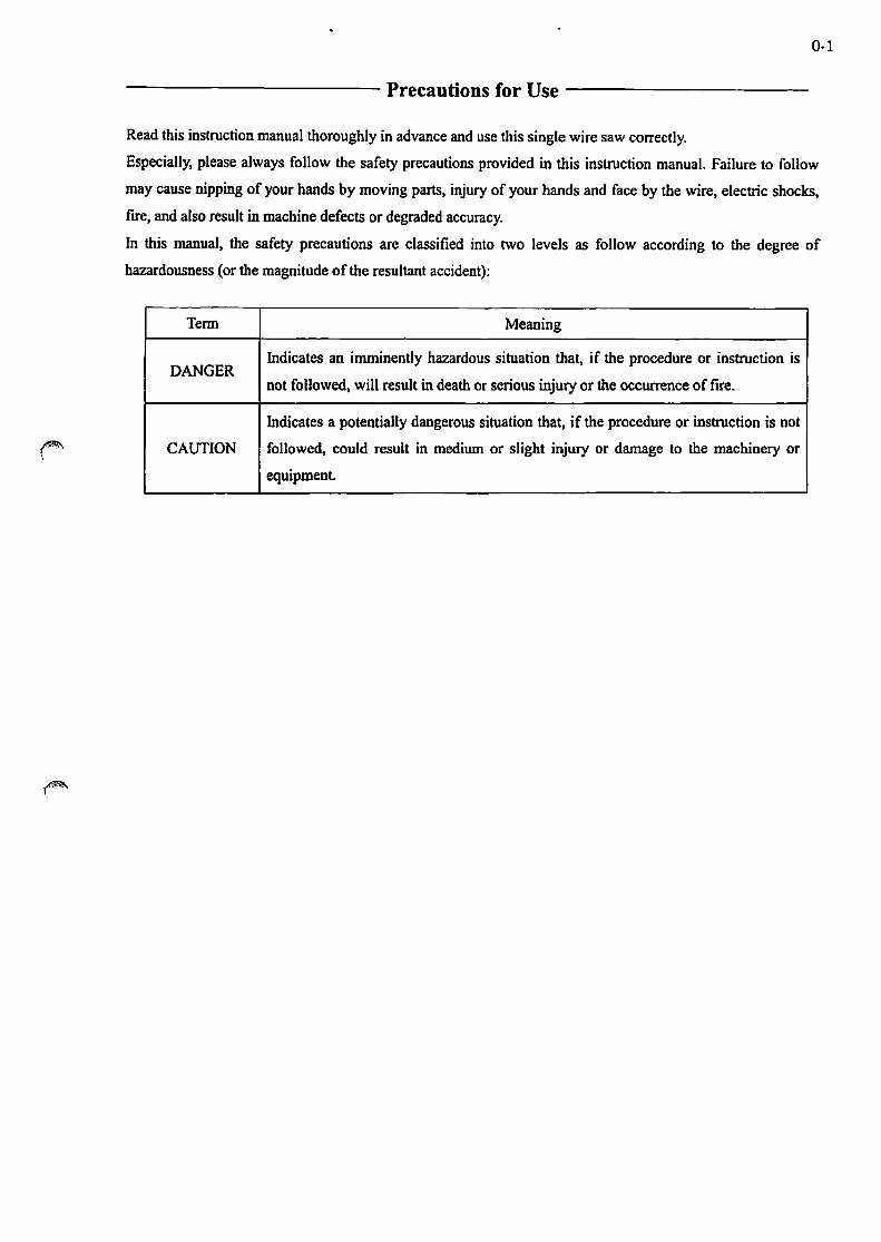
------------ Precautions for Use -----------
Read this instruction manual thoroughly in advance and use this single wire saw correctly.
Especially, please always follow the safety precautions provided in this instruction manual. Failure to follow
may cause nipping of your hands by moving parts, injury of your hands and face by the wire, electric shocks,
frre, and also result in machine defects or degraded accuracy.
In this manual, the safety precautions are classified into two levels as follow according to the degree of
hazardousness (or the magnitude of the resultant accident):
Tenn Meaning
DANGER Indicates an imminently hazardous situation that, if the procedure or instruction is
not followed, will result in death or serious injury or the occurrence of fire.
Indicates a potentially dangerous situation that, if the procedure or instruction is not
CAUTION followed, could result in medium or slight injury or damage to the machinery or
equipment.

0-2
-------- Table ofContents--------
1. Standard Specification .......................................................................... , ..... 1-1
1 -1 . Cutting Capacity ......... ............ ............ ..... ....... ............... ...... ... ... ..... ............... I-I
1 - 2. Work Rollers ................................................................................................ . 1-1
1-3. Wire ............................................................................................................. . 1-1
1-4. Wire Rocking Motion ..................................................................................... . 1-1
1-5. WorkTable············································· ........................................................ . 1-1
1 - 6. Cutting Coolant (Fixed Abrasive Spec) ............................................................ . 1-1
1 - 7. Controller .. ···························· ......................................................................... . 1-1
1-8. Motors ......................................................................................................... . 1-2
1 - 9. Machine Dimension and Exterior .................................................................... . 1-2 ~
1 -1 O. Others·················································· ........................................................ . 1-2
2. Accessories ................................................................................................. 2-1
2 -1. Standard Accessories . ....................... .... ... .......... ....... ...... ............ ........ ... ... ..... 2-1
2 - 2. Standard Maintenance Tool ....... .... ... ............. ........ ................. .............. .......... 2-1
2 - 3. Special Tools (for Work Roller Replacement) .................................. ............... 2-1
2-4. Options ......................................................................................................... 2-1
3. Names of Main Components and System Drawing ..... ..... ..... ......... ..... .... .... 3 -1
3 - 1 . Specification, Dimension and Installation Area of Machine ............................ . 3-1 3-2. Wire Saw System ......................................................................................... . 3-4
~ 3 - 3. Cutting Coolant Circulation System ............................................................. .. 3-5
3-4. Pneumatic System and Pipe Arrangement ...................................................... . 3-7
4. Machine Installation . .................................................................. ........... ..... 4 - 1
4 - 1 . Installation Location .......... ...................... ........................... .. ......................... 4-1
4-2. Machine Carry-in and Transfer ....................................................................... 4-1
4-3. Leveling ........................................................................................................ 4-1
4-4. Pneumatic Piping ........................................................................................... 4-2
4-5. Electrical Wiring ........................................................................................... 4-2

0·3
5. Cutting Coolant .......................................................................................... 5-1
5 -1 . Selection of Cutting Coolant ............................................................... .... ....... 5-1
5-2. Agitation of Cutting Coolant .......................................................................... 5-1
5-3. Supply of Cutting Coolant ............................................................................. 5-1
5-4. Cautions for Handling Cutting Coolant ........................................................... 5-1
5-5. Maintenance of Cutting Coolant Pump ........................................................... 5-2
6. Work Roller ................................................................................................ 6-1
6 -1. Work Roller Material ... ................................... .......... ............................... ...... 6-1
6-2. V-groove Pitch Selection Criteria (Option) ..................................................... 6-1
6 - 3. Work Roller Replacement .......... ................ ......................... ....... .................... 6-1
6-4. Caution for Work Roller Storage .................................................................... 6-2
7. Wire Tension .............. ... ........ ................. ...................................... ........ ....... 7 - 1
7 -1. Wire Tension Selection Criteria ...................................................................... 7-1
7-2. Wire Tension Setting ...................................................................................... 7-1
8. Wire Winding and Preparation ..... .......................................... ............ .... ..... 8 -1 8 -1. Wire Reel Installation .... ......... ........ ............. ................................... ........ ....... 8-1
8-2. Storage of Remaining Wire ............................................................................ 8-1
8-3. Removal of Used Wire ................................................................................... 8-1
8-4. Wire Winding ................................................................................................ 8-2
8-5. Fine Adjustment of Traverse Unit ................................................................... 8-3
8-6. Wire Storage in Long Period Stoppage ........................................................... 8-3
8 -7. Multi Wire Web Specification ........................................................... ............. 8-4
9. Work Table ................................................................................................. 9-1
9 -1. Work Table Mounting Space and Work Loading .......... .... ........................ ........ 9-1
9 - 2. Work Table Orientation .............. .................................................. .................. 9-1
9 - 3. Y-axis Manual Position Adjustment .................................. ...................... ........ 9-1
0·4
10. Maintenance, Inspection and Adjustment ................................................. 10-1
1 0 -1. Lubrication ................................ ....................................................... .......... 10-1
10-2. Cleaning ..................................................................................................... 10-1
10-3. Leveling ..................................................................................................... 10-1
11. Wire Pulley .................... ·.. .......... ............................. ................................ 11-1
11 -1. Wire Pulley Structure ...... ........................... ................... .............................. 11-1
11 - 2. Wire Pulley Fitting Procedure ..... ............................ .................. ........ ........... 11-1
11 -3. Caution for Wire Pulley Storage .................................................................. 11-2
1 2. Consumable Parts List ...... ....................... ................................................ 1 2-1
1 3. Attached Reference Materials .. ...... .......................................................... 1 3 -1
• Accumcy Inspection Results Sheet
• Servo Motor OperationlMaintenance Manual
• Cutting Coolant Pump Operation Manual (Option)
• Special Specification
• Others
14. Operation ................................................................................................. 14-1
15. Warranty .................................................................................................. 15-1

1. Standard Specification 1 -1. Cutting Capacity
• Maximum work piece
(Width * Height * Depth) IS6 x IS6 x 100(mm)(Caution 1)
1 - 2. Work RoUers
• Material
• Outer diameter
• Inter shaft distance
• Number of rotation
1-3. Wire
• Number of supply wire
• Diameter of wire
• Reel capacity
(Dummy thickness should be ISmm or less than ISmm)
Urethane(Using I wire is Standard Spec) (Caution 2)
Approx. <!> 120 mm x 2 axis
310mm
Max.18S7rpm
I (Caution 3)
<t> 0.12--- <t> 0.18 mm(busbar)
Sian x I coil(When winding diameter cJ> 0.2S mm wire)
• Constant tension mechanism CylinderCaution4) (Maximum tension:40N)
• Reciprocation speed Max.70Om/min
• New wire supply rate
1 -4. Wire Rocking Motion
• Rocking angle
• Rocking speed
1-5. WorkTable
• Elevation stroke
• Slicing speed
• Rapid speed
• Horizontal swiveling
Max. 200mlmin(able to set up parameter) (Caution S)
0---±10 degree(Caution6)
1---999 degree/min
Max.180mm
O.OI---ISO mmlmin
Max.ISO mmlmin
0 ...... ±7.5 degree (roughly)
1-6. Cutting Coolant (Fixed abrasive spec)
• Abrasive solution material Water-soluble, Water and surface acting agent etc. (Caution 7)
• Tank capacity Max.l2t(Min.lO t ,option)
• Pump discharge Max.2St/min (Viscosity: leSt or less,option)
1 -7. Controller
.PC
}·1

1-8. Motors
• Wire supply/collect reel motor
• Rocking motor
• Table elevation motor
• Wire tension motor
• Wire supply/collect traverser motor
• Cutting coolant pump (Option)
• In-machine cooling fan motor
l.3kW x 2 (AC servo motors)
100W + 11100 decelerator (AC servo motor)
1 OOW + 11100 decelerator (AC servo motor)
SOW x 2 (AC servo motors)
Stepping motor x 2
40W
9.5w x 2
1 - 9. Machine Dimension and Exterior
• Outer dimension Approx. 990 (w) x 1,750 (h) x 1,070 (d) (mm)
1·2
(1,895 mm height including the dimension for signal tower
light)
• Net weight
• Front cover/doors
• Paint color
1 -1 O. Others
• Rated plant capacity
• Power supply
• Air supply
<Unit Usage Caution>
Approx. 500 kg
Stainless steel
Munsell IJ2.5Y 911
6.9kVA
3-phase, 200V 1220V, SO/60Hz, 20A
0.5MPa x 150NUmin (cI> 10 air hose)
Caution 1) The 100mm depth length work is able to be installed for each front and back of the wire position.
Be careful the dummy thick and dummy cut amount when cutting the processing material reganlless its
shape.
"" )
Caution2) When using multi wires, wire sending amount margin error may be observed due to the work roller ~
attrition. Avoid usage concerned the roller attrition. In case the roller attrition was found, replace the work
roller to the replacement immediately. The margin error tends to increase with using a number of wires.
Three wires usage is recommended as maximum.
Caution3) Do not leave the wire winding to the unit that may cause wire deterioration.
Caution4) The tension range is ±15 - 20%.
CautionS) Setting excessively small amount value when the wire reel size is small that may cause wire attrition due
to contingence of wires, distortion of wires andlor breaking of wires. These causes may result some
margin error of the wire provision because of the machinery's structure.
Caution6) Limitation occurs depending on the up and down movement or the dummy thickness.
Caution7) Be careful that the usage may possibly get rusty. (e.g., Processing with only water, Processing with
processing agent may eat away the overlay, etc.)
* The specification and dimensions may be changed in order to modify the unit without notice.
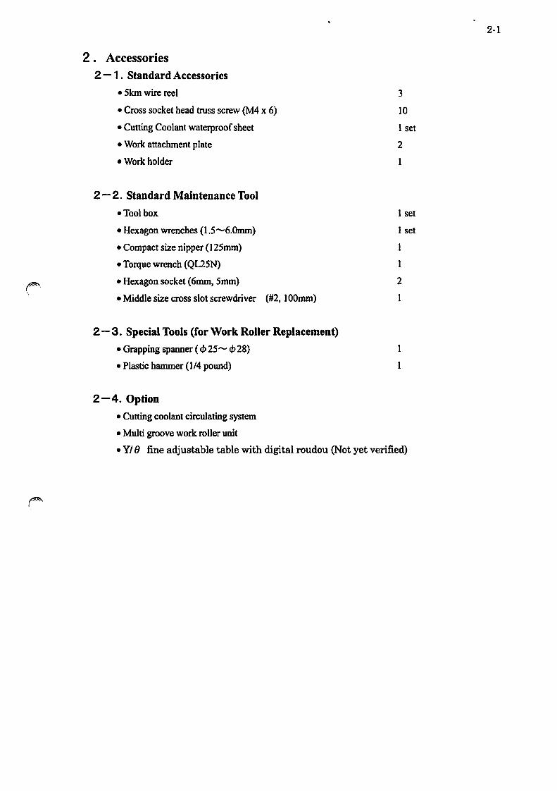
2. Accessories 2 -1 . Standard Accessories
• Skm wire reel
• Cross socket head truss screw (M4 x 6)
• Cutting Coolant waterproof sheet
• Work attachment plate
• Work holder
2 - 2. Standard Maintenance Tool
eTool box
• Hexagon wrenches (l.5 ....... 6.0mm)
• Compact size nipper (1 25mm)
• Torque wrench (QL2SN)
• Hexagon socket (6mm, Smm)
• Middle size cross slot screwdriver (#2, lOOmm)
2 - 3. Special Tools (for Work Roller Replacement)
e Grapping spanner ( c/> 25 ....... c/> 28)
• Plastic hammer (114 pound)
2-4. Option
• Cutting coolant circulating system
• Multi groove work roller unit
3
10
1 set
2
1
I set
I set
I
2
I
• YI () fine adjustable table with digital roudou (Not yet verified)
2·1

3-1
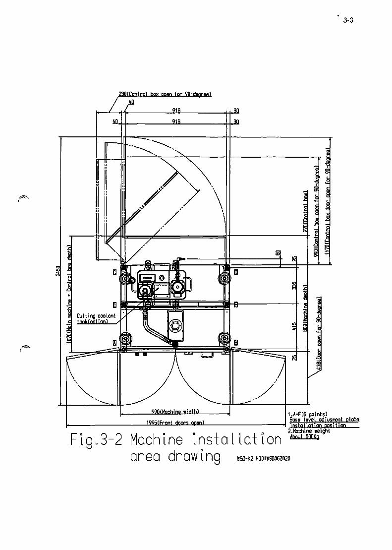
3. Names of Main Components and System Drawing 3-1. Specification, Dimension and Installation Area of Machine
Table 3-1. Specifications
Model WSD-K2 Wire run method Single wire run with reciprocation and rocking
Maximum work size 156 x 156 x 100 (width. height, depth)
mm (Thickness of Dummy should be less than 15mm)
Outer diameter mm Approx. t/> 120 mm x 2 axis r;'~ Inter shaft distance mm 310 -0
Rocking angle if~ degree 0-±1O Rocking speed deglmin 1-999
Number of supply wire # 1 Diameter of wire(fixed abrasive) mm t/>O.l2- t/>O.l8(busbar)
Max. wire on reel capacity kIn 5
(Wben winding diameter ¢ 0.25 mm wire) ~ ~r Constant tension mechanism Cylinder (maximum tension: 40N)
Max. reciprocation SPeed mlmin 700 Max. new wire supply rate mlmin 200 (able to set up parameter)
Reciprocation mechanism WIre servo motor nonna! and reverse rotation New wire feeding mechanism Wire supply servo motor normal and reverse rotation Max. elevation stroke mm 180
g.~ Slicing speed ounImin 0.01-150 (i"~ Max. rapid speed mmlmin 150
Horizontal swiveling degree 0-±7.5 (roughly) Abrasive solution material Water-soluble, Water and surface acting agent etc. (fixed abrasive spec)
n (j Max. tank capacity 8 c liters 12 (Min. 10 t) g-g. (option)
_00 Max. pump dischmge rate
(option) liters/min 25 (Viscosity: leSt or less)
Wire supply/collect reel kW AC servo motor: 1.3 x 2 Rocking W AC servo motor: 100 (deceleration rate: 112001
:: Table elevation W AC servo motor: 100 (deceleration rate: 11100) 0 Wire tension W AC servo motor: 50 x 2 0 li! WIre supply/collect reel traverser Stepping motor x 2
Cutting coolant pump (option) W 40 In-machine cooling fan W 9.5x2
Powersup~y Ph-V 3-2001220 Rated plant capacity kVA 6.9
0 MPa-~ Air supply 0.5-1 SOC ¢ 10 air hose) ~ Nt/min
Machine Outer dimension mm Approx. 990 (w) x 1,750 (h) x 1,070 (d)_ Netweigbt Kg Approx.500

~
,
)
f
~ ! ,--,
? j ~ c: ~
E cS
.~ ~ ~ 9
m ---' .- --'
~ ~ ~ ~ ~ ~ .~
~ ill
)
-~ >
~ ~ .
~ .;1 ~
~ g
t .......-; ~
990
II=i Ii:l
"" 0 0 ),9t~ 1 /"':.-=. ~:--.J
r( Ii' "',\ I~( t: \\ ! \ ~V ~ .. ,,}
~-IIJ ,,--1::1 I:: ~
(1 r-.,,~ ~ ....- ~ ~ ~ ~ v ~~ ~ \"'~
~ ~;:# i.I
V. \. .... ~~ ~ ~/ tl II '~ -"'- J"L
.1£ ~ ~c D. ~rg -n ~ . ; .
I· ~ .. !III~ ILIII CD
~ •. I" "
c ~ ~ '---
I· v·
~ I
"/x.·' . . l ~
• . EJ _t ~ - - - - - -
FIga3-1
~ ~ t: ~
~ ~
---'
~ ~ as cS ........
.§
.§
~ Ql .~ ~ :c: ] 2:
~ ~ ~ ~ ........
t.
41
3-2
Please select A or 8 for power suppl~
• •
• •
• •
o •
• •
• •
",.--"
"~-.
~ol"ltro II ox
Over a l l V I ew WSD-K2 MQ01WSD06Z030
3-3
I.A-FC6 points) Bose level odjusment plote 1--_______ .l.ZLI1D3ImJl!l!oI!:li.....\4l!aJL _______ -I instgllgtion posit ion
2.Hochine weight About 500Kg Figa3-2 Machine installation
area drawing WSO-K2 MOOIWSO06Z020

3-4
3-2. Wire Saw System
Fig. 3-3 Machine Front Part
1. Rocking plate 7. Supply wire reel
(connected to the timing belt for rocking motor) (connected to wire supply motor and supply """"',
2. Work roller (Standard: 2 axis) traverser motor)
3. The way of wire when 1 wire is used 8. Collect wire reel 4. Way of wire when several wires are used multi (connected to wire collect motor and collect
wires traverser motor) 5. Supply wire tensioning pulley 9. Supply sub pully
(connected to wire supply encoder) 10. Collect sub pully
6. Collect wire tensioning pulley
(connected to wire collect encoder)

3-5
3-3. Cutting Coolant Circulating System
Fig. 3-4 Cutting Coolant Tank (Option)
l. Cutting coolant supply pump 7. Cutting coolant supply hose
2. Cutting coolant tank and lid (to machine internal part)
3. Cutting coolant tank main valve 8. Tank connector
4. Temperature detector port (option) 9. Pump cable
5. Cutting coolant colleting port (filter) 10. Relay box
6. Cutting coolant supplement point 11. Coupler 12. Duct for returning cutting coolant

3-6
Fig 3-5 Pipe Arrangement
Fig. 3-6 Work table unit
1. Work attachment plate 3. Cutting coolant nozzle 2. Slicing material 4. Nozzle valve

)
)
3-4. Pneumatic System and Pipe Arrangement
Wire Tensior'le"
I --------------------------~
CM2XD20-i 25 w-s ee lnoer-
lSE30A-Ol-N-MlB Hi r-- Lr." e L itol ... e sw
VEXl133-0' -B Precise re lo~o'"
SY322Q-5LZE-C6 So enola voLv
<141
\
Wire teosioner L
I ,;
~ ,
, l.
Wire tens loner R
C~.2XD20-125 11;-5 eed inder-
~ -125S1
~Q rr I !S~30A-Ol-N-MlB ~ Hjgr-aeeurate digital pressure swjten
P q;; R VEX1133-01-8
~~ Pr -ise r ctac
ct6 ct6 SY3220-SLZE-C6 SY3000-26-9A SOLenoId valve Blonktng plate Ass'y
r-.-r---TA+' --f'B_,/ /
I
I /
Ir-~--------------------------~ IIr---------------------------,
II, <14 W' I d •• 't \ II ; Ire ree ,r I v I ng un I III 1.3kW M III III III 1'1 III III
~~ -----~----------~ ~/ ---------------jl
~ 1t ro, -' ~lue·O,03MPa I I
, "
@) , ARQ2-C286-1 Regu lator [C.C -O,OMPo)
" I' I'
o +Limit
:' '""'~u-" II -Limit -0
SY7120 -5LZE-C6-F2 ~ lee
IpL~ So lenate' valVE'
I ~ r---...i
: L - - - - - - - ~m~t - ",- T -- 'T I
~ -----:~~i;:; l~~,Y~ t::i~ I <Ill
i)-I
I svmboll Items I Model f,'tv I 7' rio l f -lnuon ' KO:>HI0-0?S 1 2 -{ !::\QJ f -\,JJ1uon w' th nexooor'l ho i c i KO?S08-0?S 1 .., I KO:>SOfi-oiS ,
1 , I I K5iS04-D 1 S 3 7t" i KO?S04-M'i ? ;I) 1= lbow mton I KO?I 1 O-O:>s(1 n-:IIJriR MRO::l ::l 'i'- I KQ?iOF-01S 6 ? I I KO?I 08-0?S I 1 'T I KQ2L04-M5C lnclurie MR02l 4 ::J I K02104-01S -3 "1 Sooed. "antra ller i AS??01F-01-06S ? :" D..uo l speed CO"lt ro il er I ASD~~OF-Ol-0RS I 2 ::z IP luo ' M-'iD(MR011~- t-) 1
I ') _Branch elbow _un i on I KO?I U04-01 c; 1 '9 Female nion I KO:>FOR-01 , :> T !Both-end tees union l KbiTOa-02S ! 1 ':J ISe"v i r.e JlillLun i on KQ?Y04-n1" 1 ., ITriole brancb niversa' elhnw KO:>7T04-0?S 1 to- Plua Koip-08 I 1 1" 'S nk nluc MSWTMK1 Q
Sllence~ AN103-01 -5 :;z F'iuo I K(l?P-04(ln('lude MB01l ? -* Unior'l Y KO:>IJ04-00 I 1 ) 'SUr'lk olua iMSWTS?(lnclude ~l I 1 /\ Hose nipple VHN3/8x1?7SL!S I 2 t: I VHN1/4x1[,.o;SUS I 4 ? !::'bow I Vi 1/4SCS 4
, "- !Hexaoon nioole V6N1/4SCS 4 ;j; IStreet "lbow VSTI/8SCS I 1
" =,bow VI '</8"r:" I 1 ~ Mpole vN37Bsus I < , 1.. Cross VX3/8SCS I 1 ;I- SUr'lk Plu" M§iTSQ ,
1 'E Diffe:ent er'lc ntoole VRNV8X1/4SC:S 1 i' IBoth-lone n 1 00 le VLN1/4X150SUS I 2 ~ ".~~~~~~~~-~S\~I!±L~~~~~~I~
~A; 'rt 0 ~--~p~r'~--------~~----------------~r~------------------~P
~~: ffiffit:======~~======~~==~'====~~======0 Front late ~ I .tliDLs''igle web,' . Use 1 pes(::Z) & 1 pcs[;;<l.Not use 1 pes('Tl
'" W 1 re mu I ti web' . . Use " p::s ( '7), Not use 1 p::s [ ;;:.) & 1 pes ( :;z)
G wtl""e :ension L Wire i:er"!Slon R Spc"'e EB
!S1000~-3002-X2-\5 P"essu"'s swtch with pipe adapter ¢8 ! ~.£ i
La. presscredetec1 ion ~ I Backside cove"' sett lno C.3t.1
Po I I
;;;-~~~~ilr Ii" I -- ~ I
Atr(For drivel
1- - - l\lr porge
Cut-( i r'lC coo 10'1t I'
L-- ~ ,
AC30B-02CG Air combinaHon
SS5v3-20-03 Man,fald
r--------------------------------.J
r"\ I C rneumatlc
Cutting Coolant nozzLe
S'-9XL2.0~ Super tetrani" hose I HBG15 Plate those oand
L ___ ~ r---------II I I;vIiLno coolor'l+ tOr'lk unltcOPTIONl I I'
! I ,
------------! UTKMW1!4 160G 3a!: v ve
~CSAJ2-3-1-0' Aajust hose filn
, , ~ II l\ 1"11 vlo~k 'I L.~-
BMAFRi-C2-R3-S2 Air blaCK term,nal I
I I I ' '-------------~
System and Ploe I
Arrangement WS2-K2 MJ01WSD06Z03D

4-1
4. Machine Installation 4 -1. Installation Location
Install the machine on a floor surface rigid enough to support the net machine weight (approx. SOOkg) and
free from direct sunlight and vibration. It is strongly recommended that you install the machine in a
• It should be also noted that you should decide the installation area of the machine, by referring to 3-1,
"Overall View" and "Machine Bottom Plan View" in consideration to slicing operation, cutting coolant
supplement, machine maintenance, process and extension planning.
4-2. Machine Carry-in and Transfer
Transfer the machine by hooking the four eyebolts eM 16) located on top of the machine with hoisting
device. In this case. make sure that the machine is carefully hoisted in a good balance to prevent shocks. If
hoisting is not available. move the machine carefully on the casters or a forklift track in a good balance.
When moving the machine on a forklift. inserting metal fitting for moving in the back of the machine for
4-3. Leveling
Put a water level on the work attachment plate placed on the work table located in the lower part inside the
front door as shown in the Fig. 4-1. Check the levelness and tum the adjustor feet (M16) in the bottom of
the machine by a spanner. Please check the levelness every year in the annual inspection. If raising the
adjustor too high. the machine may fall and please keq? the clearance under the machine as lower as 10mm.
14iMi" Please refer to "3-1 Machine Bottom Plan View" for the location of adjustor feet, A, B, C, D, E and F.

4-2
4-4. Pneumatic Piping There is a joint (R1I4) for air supply connection under the control box. Please connect c/> 10mm (inner
diameter: 6.5mm or greater) hose to the joint and add a cock to the supply source. In this case, air pressure
should be O.5MPa and the consumption rate be lS0NVmin. If the pressure is lower than 0.3MPa. the
4 - 5. Electrical Wiring
The power connection terminal (R, S, and T) is located in the breaker in the left part of the control panel on
the back of the machine. The power supply (3-phase. 200V, SO/60Hz. capacity: 30A) should be connected
to the control box through either the hole of the bottom of the main machine frame or the top cover. To
prevent malfunction of the machine. it is necessary to restrict the voltage fluctuation within ±10% of the
rated voltage and supply earthing by earth bar. After connecting the power. read and understand this
Check the supply air volume with the main regulator and confirm "WSD-K2 TAKATORl WIRE SAW" is
shown in the touch panel screen, and then press the drive power switch under the emergency button in the
front panel. Then, if touching the touch panel, the main menu screen will be displayed. Please press the
reset button to reset the alarm shown in the touch panel if any in the procedure so far. Cfhis step is

I!'PI \
5·1
5. Cutting Coolant 5 - ,. Selection of Cutting Coolant
Please apply water-soluble agent or water for cutting coolant and add surface acting agent where necessary.
Determine the proportion of the surface acting agent according to the cutting requirement and condition. Be
careful that the usage may possibly get rusty. (e.g., Processing with only water, Processing with processing
agent may eat away the overlay, etc.)
The capacity of the tank unit (option) is 10 - 12 liters. (The filter for returned coolant is soaked in the liquid
a little when 10 liters of it is poured.) For normal operation, connect the coupler and the connector, and then,
push the tank under the machine paying attention to the return duct. (The casters have lock feature.) Check
In case this tank unit (option) is not installed, please connect customer supplying hose with the cutting
coolant supply hose connecting part directly (see Fig. 3-5).
5-2. Agitation of Cutting Coolant
This tank unit (option) has automatic liquid agitation feature to prevent deposition. Pour cutting coolant into
the tank, fit the pump and hose in the tank and then close the main valve of the pump discharging port.
Then, press "Agitation" button on the main display of the touch panel to start agitation. To keep the
uniformity of liquid's density, cutting coolant should be agitated well during the night when the machine is
5-3. Supply of Cutting Coolant
After completing the cutting coolant agitation process above and the wire winding process explained later.
set the liquid discharging nozzles on the sides of both left and right work rollers so as the liquid can pour the
point where the material and the wire contact each other. In this point please adjust the position of the
Open the valve of the nozzle and attach the waterproof sheet, then press "Discharge" button in the main
display in the touch panel screen. Next, if opening the main valve of the discharging port of the pump
gradually, the cutting coolant is supplied to the nozzle through the hose. The cutting coolant thus supplied is
not only used for slicing workpiece but also. as an important medium. removing the heat generated in the
slicing part, minimizing the relative thermal deformation that occurs around the slicing unit
5-4. Cautions for Handling Cutting Coolant
In replacing cutting coolant, when removing the coolant pump outside of the tank, never lay down the
coolant pump on its side nor turn it up side down. Because it may cause vibration and noise or the
malfunction of the tank. if the cutting coolant in the bottom of the tank pours into the upper part of the tank,

5·2
5-5. Maintenance of Cutting Coolant Pump
( 1) Caution for burnout
(2) Daily Maintenance
During opemtion. always check whether the pump has vibmtion and noise and clean the exterior of the
pump regularly. And. to avoid foreign particle catching inside the pump. clean the inside of the tank
and re.place cutting coolant regularly. ;'lit.A (3) Others
Please read the operation manual of the cutting coolant pump. [4"t.l$

~ \
6-1
6. Work Roller 6 -1. Work RoUer Material
The work roller is an important part that affects the processing accuracy and resin (ultrahigh polymer)
material has been used for the work rollers in our conventional line-ups because of its ease to cut, fitting
well with wires, low cost, etc. However, for this machine, we adopt urethane rubber for the work roller
material, which is known as wear resistance material. Urethane rubber is better in anti abrasiveness than
resin and the lifetime of urethane is longer than that of resin. Thus, urethane is more advantageous in the
running cost than the resin material in terms oflabor saving in work roller replacement and the reduction in
management.
6-2. V-groove Pitch Selection Criteria (Option)
The slicing stock is greatly influenced by the elements, such as
''wire diameter" and ''work piece material". Moreover, it will be
somewhat affected by the set slicing conditions such as new wire
supply rate, cutting speed, wire tension and rocking unit angle and
speed, and wire weariness status. For the initial trial cutting, the
selection of criteria for V-groove pitch is generally obtained as
follows: (See Fig. 6-1)
(
Slicing stock (S)= Piano wire diameter ( cb D)
V-groove pitch (P) = Target thickness of slicing (T) + Slicing stock (S)
p
T s
F· 6 115O-K2 l g. - IIOOlISDnSZD20
J To determine the V-groove pitch finally, tIy increasing or decreasing new wire supply rate and testing
cutting a few times to seek for the most appropriate value.
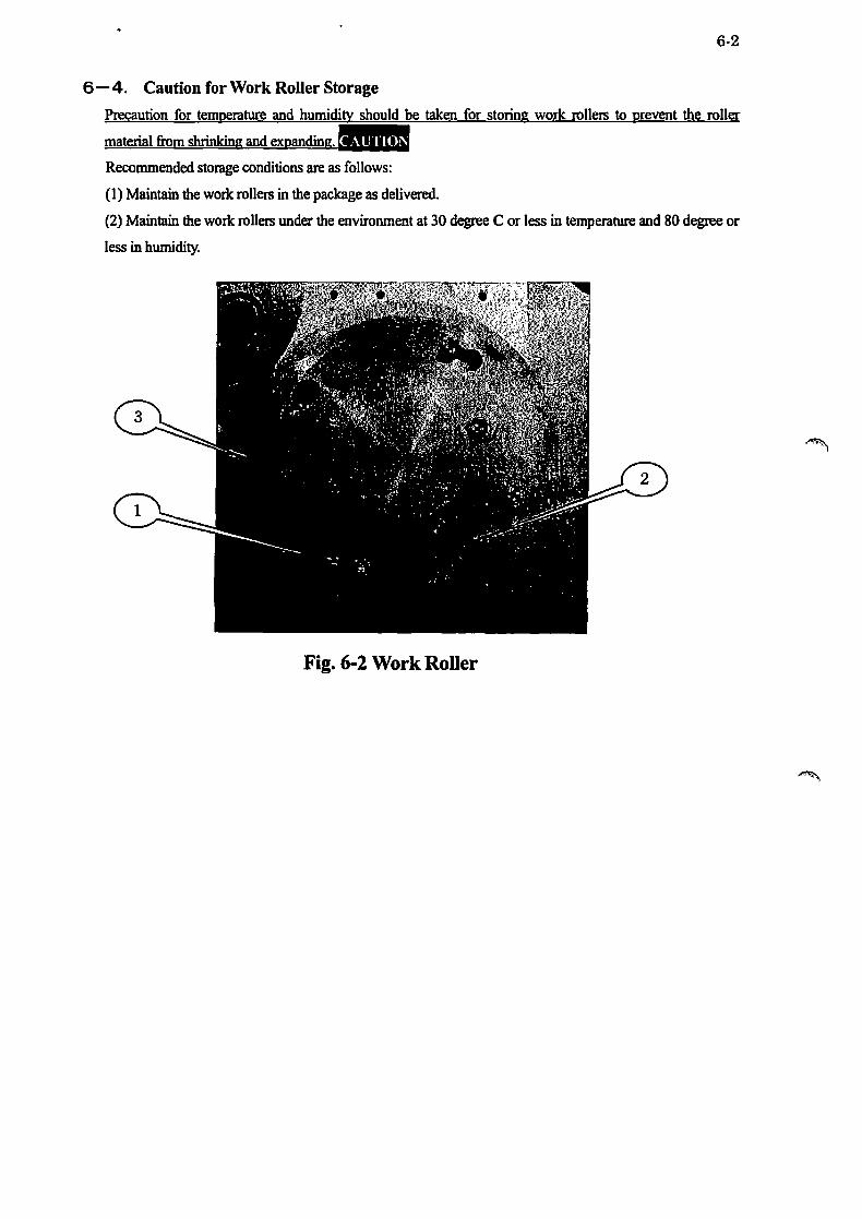
6-3_ Work RoUer Replacement
When the machine is shipped from our factory, the work rollers are installed as in Fig. 6-2. Please replace
the work rollers regularly before the V-groove is worn out To replace the work rollers, loosen the four
pieces of the bolt (1) and tum the aluminum holder plate to the hole and take off the plate, then, remove the
work rollers (3)
The work rollers used in the machine can be used two times by reversing. When replacing the rollers.
always clean the attached cutting coolant around the work rollers or wash them. If washing the work roller.
Please see the table 12-1 and we recommend you keep the spare parts in the list. When replacing "Work
RoUer Assembly Unit Parts", we recommend you purchase a set of the parts that are assembled in out
factory.
6-2
6-4. Caution for Work RoUer Storage
Precaution for temperature and humidity should be taken for storing work rollers to prevent the roller
Recommended storage conditions are as follows:
(1) Maintain the work rollers in the package as delivered.
(2) Maintain the work rollers under the environment at 30 degree C or less in temperature and 80 degree or
less in humidity.
Fig. 6-2 Work RoUer

7-1
7. Wire Tension 7 -1. Wire Tension Selection Criteria
The wire tensioners, which give rigidity to wire, are installed both in the wire supply and collection units.
The higher the wire tension is, the better the slicing performance (accuracy and productivity) is. However.
extremely high wire tension causes wire breakage. short lifetime of work rollers and wire pulleys. (There is
a fluctuation in the tensility value ±J 5-20%. and it doesn't lead to breaking directly. but swing to left and
7-2. Wire TensioD Setting
Setting and changing wire tension are descnbed as below:
The mechanism of wire tensioning in this machine is air cylinder method and the tension is adjusted with
the air regulator located in the under left part of the machine front face. (please see Fig. 7-1) Those pressure
values can be obtained through the touch panel by inputting wished wire tension. Please turn the tensioner
regulator Land R checking the pressure indicators Land R so as to show the same pressure values obtained
in the touch panel.
Pressure indicator (L) Pressure indicator (R)
Tensioner Air regulator (L) Fig. 7-1 Tension Setting
Tensioner Air regulator (R)

8·1
8 . Wire Winding and Preparations 8 -1. Wire Reel InstaUation
Attach the wire reel (Fig. 8-2) in the reel shaft part (Fig. 8-3) as shown in Fig. 8-3. In this point, insert the
reel shaft positioning pin (2) into the wire reel positioning pin hole (1). There is one positioning pin on the
reel shaft.
After attaching the wire reel. attach a washer. dish spring (round face to front side), and then. M8 x 20L (bolt
Fig. 8-1 Wire Reel Fig. 8-2 Reel Shaft Fig. 8-3 Reel Installation
8 - 2. Storage of Remaining Wire
The total extension length of the wire wound in the wire supply reel can be calculated according to the
length of new wire and the total length of wire running. (There is some gap arose during winding) When
you replace wire reel, always input the length of the wire on the wire reel in the touch panel monitor. This
value changes according to wire and can be checked in the touch panel anytime. Please input the
Also, you can check the wire remaining volume through (3) inspection slit on the rim parts on both reels"
8-3. Removal of Used Wire
After slicing, extreme fatigue and wear have been built on the wire on the coUection reel. Therefore, in
principle, the old wire is thrown away after single use. Please take off the wire reel when the wire is
wounded on the reel on some level. (The volume of wire can be checked through (3) inspection slit) In case

~ \
8-2
8-4. Wire Winding
Wire winding work should start with the settings in "Standby Display" in the touch panel after completing
the steps in "4-5. Electric Wiring". To start this work. you should open the machine front door and remove
(1) Preparation forWmding
First, adjust the air pressure of the tension cylinder. (please see 7·2.) Turn on both tension L.R and
adjust the regulator to set the pressure at O.05MPa. Then. turn otfboth tension Land R
(2) Wire Wmding
After completing preparation for winding. install supply/collection wire reel. (It is easier to install the
reel while the servo motor is on.) Please turn otfthe servo motor then and turn the reel while feeding
the wire little by little as shown in Fig. 3·3. In this point,
Hang the wire in the front groove on the work roller and then on the rim part of the collection wire reel
for two times. The dcmth of the reel is 38mm. Please wind the wire on the front part of the depth. Then.
put the end of the wire through (1) the hole and wind it around (2) truss head screw as shown in Fig
Fig 8-4 Wire Winding
(3) Tension Control
After completing wire winding. close the front door and turn serva.on the wire reel motor. Next, turn
on tension L and R. and then. tension control in order and set the wire tension referring to the section
7·2. ~~~~!Mi!~~~~~~~!LQ!J~:L.JJ[illL~~~L.ill!l:.ru:ml!l!g!!y

8-3
(4) Operation Start
After completing the wire on reel diameter and confirming the measured value is effective, once set the
process condition arbitrary by setting positions such as elevation etc in the manual display before
operation. Also. to make the operation stable. run the wire for 3 to 5 meters to the collection wire reel
in the index operation. (4'Iit.1$ Then, set enable/disable of automatic removal, operation mode, speed of cutting coolant pump etc. and
turn the mode to automatic check all the settin s are correct and then start 0 eration.
But the location of wire from a supply wire reel to a help pulley should be fixed vertically. (To prevent
wire derailment and abrasion one side). Even when already adjusting it once. there is a fear that a
location difference occurs again by accumulation by a mechanical error of the book state. It is
8-5. Fine Adjustment of Traverse Unit
Operate the machine and check in which A or B way in Fig 8-5 the wire is wound, and try fine-adjusting the
positions in the front and back traverser positions by inputting the value below into the common data of the
touch panel and see if the winding improves.
rA):add +O.Smm to both front and back traverser position
UB):add -O.5mm to both front and back traverser position
Machine Frontside 1----1
CA) CB)
Machine Backside
Fig.8-5 Fine Adjustment of Traverse Unit WSQ-K2 MOD1WSD06Z020
8 - 6. Wire Storage in Long Period Stoppage
Leaving the machine for a long period (such as new year holidays) with wire wound may cause
deformation of the work rollers and rust on the wire. or lower accuracy. In this case, please cut the wire on

8-4
8 -7. Multi Wire Web Specification (Option)
In this machine, single wire is hung under the work rollers. Wire arrangement as in Fig 3-3 is standard. In
option specification, multiple wire can be wound on work rolJers a few times just like our multi wire saws.
This is called "multi wire web". To apply the multi wire web specification. some parts should be replaced
and added
(See "6-2 V-groove Pitch Selection Criteria".)
(1) Preparation for Winding
After completing the steps in "8-4 (1) Preparation for Winding". please add the parts for multi wire
web. In this case, the work roller unit (including the urethane part) should be of multi wire web
specification. Please note some components in this unit are different from single wire specification,
such as using one more work roller.
Spacer(s) is to be added for multi wire web application. Those are used for changing the position of
collection side tension and sub pulley unit to the front. In Fig 8-6. the I-mm thick spacer is fitted and
151
Q) +-' C ~
-1(S ocer) 0- -1 (S ocer) +-' C 0 '-u.
Fig.8-6 Multi Wire Web Additional Ports(Example) WSD-K2 MO01WSO06Z020
Q) +-' C ~
0-
+-' C 0 '-u.

-
J
8-5
(2) Traverse Position Setting
After completing the preparation for wire winding as above, the front and back positions of the
collection traverser should be changed. This is also because the distance from the front plate to the
wire is to be changed in the multi wire web specification. The same reason of 8-7-( 1).
should be input
(3) Wire Winding
After completing the procedure above, install the wire referring to "8-4-(2) Wire Wmding". However,
see Fig 8-7 for winding wire on the work rollers, that is, hang the wire vertically against the work
rollers under the rollers, whereas diagonally on the top of the rollers. (It is possible to use both side
of third added work roller)
Wmd the wire in the groove on the back in the supply side and lead the wire to the front and finally
wind the wire in the groove on the front in the collection side.
Wire D
In
I j
Work roller upper side
Work roller lower side
I --------
Wire out ------------
\ I --------
\ --- ~ ---~-------!------ r---------!------ r---------!------I- - i I- - l-
I
I []
I
I
Fig.8-7 Work Roller Unit Multi Wire Web Top View
WSD-K2 M001WSD06Z020
I
I
*An error of sending wire length is occurred by work roller worn out one way. Please avoid using a method
caused abrasion of work roller and if you find abrasion of work roller. please change a work roller as soon as
possible. It is recommended to use until 3 wires because abrasion gets serious when more than 3 wires are used.

9-1
9. Work Table 9 -1. Work Table Mounting Space and Work Loading
The dimension of the work attachment space is 156 (w), 156 (H) and 100 (D) (rrun) as shown in Fig 9-1.
Please learn the locations of (1) work table, (2) attachment plate, (3) dummy plate and (4) material in the
figure. (Fig 9-1)
(1) Work table is fixed on the (S) table base (fable base is fixed on the (7) clamp nut) with (5) swivel base
and (6) positioning pin. (5) Swivel base is fixed on the (9) spacer higher place than slide quill which moves
up and down by servo motor and ball screw. Clean the bottom and side faces of (2) attachment plate, which
is attached with (3) dummy plate and (4) material, and the (2) attachment plate fitting face and both sides
faces of the (1) work table, and (10) holder, and then, put the (2) attachment plate on the left side face of (1)
work table, then fix it on the slicing position tightening (11) clamping bolt (6pcs, M6 x 20L, with round top).
9 - 2. Work Table Orientation
At shipment of the machine, the attachment plate's mounting face of (1) work table is fitted in vertical
relationship with the front plate. That is, the step 0 of (13) sub scale is aligned with the step 0 of (12) angle
scale plate. In case the orientation needs to be adjusted because of crystalline layer alignment etc, the
orientation can be changed up to ='7.5 degree.
To adjust the position, loosen the (14) work table fixing bolts (MS) on the right and left sides and, when
needing to tum to the right viewing from the top, loosen (15) left adjust bolt in the front and tighten (16)
right adjust bolt, press (6) positioning pin fixed on (S) table base. Then, adjust the orientation. And then,
tighten (15) left adjust bolt lightly and (14) work table fixing bolts on both sides. When needing to tum the
work table to the left, cany out the steps in opposite positions. (Work size may be limited depending on the
table orientation.)
9-3. Y-axis Manual Position Adjustment
Please learn the wire position (IS0mm from the front plate) and work mounting related dimensions in Fig
9-1. To slice the material whose depth is 100mm or shorter in equal thickness, loosening (11) clamping bolt
and adjusting (2) attachment plate attached with (4) material are necessary.

@Holder orientation
~~aMp~n~ bolt tigm<ening ~orqu, 9- , N· M(SO-7 gf· eM
Fig.9-1 Work mounting related view WSO-K2M1l01WSO06Z020
9-2
~ I
1 O. Maintenance, Inspection and Adjustment 1 0 -1. Lubrication
(Lubrication for Ball screw, LM guide and Rocking shaft)
Apply grease (approx. O.6cc) to the parts semi-annually. [ 141,1I'1"llltl"-
1 0-2. Cleaning
10·1
When cleaning the machine in supplementing coolant and consumption parts or replacing wire reels.
Moreover. never apply cleaning liquid directly to the tension pulley unit wire reel unit shaft. and rocking
unit shaft because the cleaning liquid may flow inside of the machine through the units. (Electric
components may be wet with the liquid.) "s,saih lease use rust remover.
1 0-3. Leveling

11·1
1 1. Wire Pulley 11 -1. Wire Pulley Structure
The wire pulleys of the machine (fension Pulley. Sub Pulley) are designed to be located in ISOmm position
from the front plate as shown in Fig 11-1. So the position do not needs to be adjusted. However. always
Please see Fig 11-1 for the detailed structure.
150
Q) -+-' a ---'
0....
-+-' C 0 L
1..L
Fig.11-1 Wire Pullry Ttructural Drawing WSO-K2 MQD1WSDD6ZD2D
11 - 2. Wire Pulley Fitting Procedure
Q) -+-' a --'
0....
-+-' C 0 L
LL
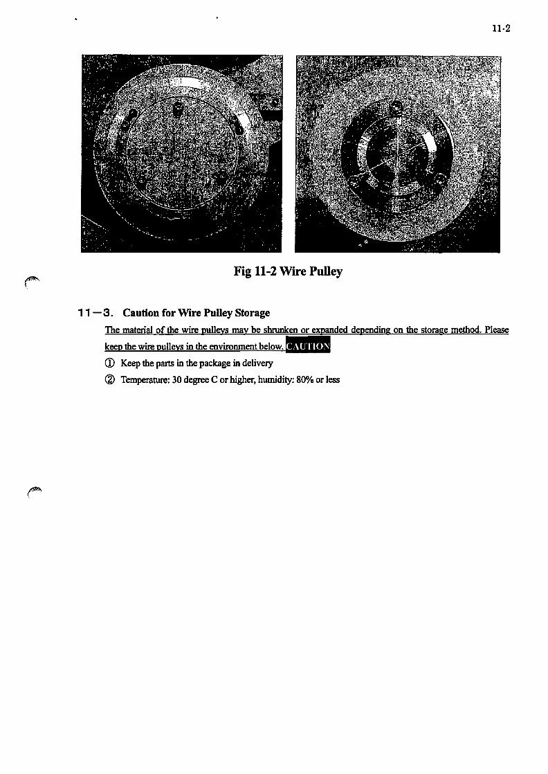
The wire pulley is fitted as shown in Fig 11-2 before shipment Please replace it regularly before V-groove
is worn out Please clean off the cutting coolant around the unit or wash away. And also. in washing pulleys,
Wire pulleys should be stocked constantly as spare parts and we recommend, from a maintenance
standpoint, that you regularly stock a set of pulley assembly unit for the purpose of "refresh replacement" or
"Wear inspection" referring to Table 12-1
11·2
Fig 11-2 Wire Pulley
11 - 3. Caution for Wire Pulley Storage
CD Keep the parts in the package in delivery
® Temperature: 30 degree C or higher, humidity: 80% or less

12·1
1 2. Consumable Parts List Table 12-1. Consumable Parts List(University of California Specification)
(See Fig 3-3, T :stock constantly)
------- Items PlN,Model Material Q'ty Remarks
T 60 Degree groove
MJOI WSD060020 SFf-I09ST 1 r/> I04x r/>90x IOL pulley(K2)
Tension shaft (D cutting) MJOI WSD060030 S4SC 1
Bearing cover(l) MJ02WSD020180 A2017 1
Bearing cover(2) MJ02WSD020160 A2017 1
Pulley holder MJ02WSD020170 A2017 I Tension
Washer for bearing QWE06030SUS SUS 1 Pulley
Bearing 600SW 1 NSK (2sets)
O-ring S60 1 NOK(apply grease)
Hex socket head screw M2.Sx12 SUS 3
Hex socket head screw M3xl2 SUS 3 Cross socket head
dish screw M6x8 SUS 1
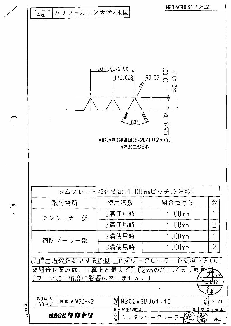
T WorkroUer (r/> 120x tSL) MB02WSD061110 SFf-I095T I (p:I.000,3 groove)
Bearing case MBOI WSD060071 A2017 1 For multi wire web
Work roller shaft (I) MB02WSD060010 S45C 1 For L work roller
Work roller shaft (2) MB02WSD060020 S45C I For R & U work roller
Cap MBOI WSD020050 A2017 1
Pulley holder MBOI WSD060020 A2017 1
Angular bearing 700SCDB 1 NTN
Work rollers Helisert M4-D.7X2DNS 4
(3 sets) Metal washer WSSM30-8-S 1 Misumi
Dish spring washer GTS8 1 Misurni Socket head cap
MSWTMJ 1 Misumi screw
O-ring S44 1 NOK (apply grease)
Hex socket bead screw M8xl5 1
Hex socket head screw M4xlO SUS 4
Hex socket bead screw M4x12 SUS 4 Hex socket bead screw
+ spring wasber M3x5 SUS 30 For only L work roller

12-2
-------- Items PIN, Model Material Q'ty Remarks
~ f/> SOx6L deep groove
GIMWS08027 Urethane I f/> SOx ¢ S9x6L wire pulley({])
Sub pulley shaft MW04WSD060160 S4SC-Q I
Sub pulley cover (1 ) MW04WSD060 140 A2017 1
Sub Pulley Sub pulley cover (2) MW04WSD060 ISO A20l7 I
(2sets) Washer (A) QWA04012Z4 SPCC 1
Bearing 600SW I NSK
Hex socket bead screw M2.SxlS SUS 3 Cross socket head
dish screw M4x8 SUS I
Wire reel Wire reel ( f/> 220) MHO I WSDOSO 140 A2017 3 Empty weight:2kg(supply, collect)
Include 1 for spare
Work Attachment plate MDOI WSD0600lO SUS430 2 Include 1 for spare
attaclunent plate Top plate MU16WSD0600S0 SUS430 2 Include 1 for spare
-<For work attachment jigl
Rocking belt Timing belt 250S8MS20 I Mitsuboshi
Elevation belt Timing belt HTBN750SSM-2S0 I Misumi
Lilhiwn battezy Battery JZSP-BAOI I Yasukawa for motion controller

13-1
1 3. Attached Reference Materials
• Accuracy Inspection Results Sheet
• Servo Motor Operation/Maintenance Manual
• Cutting Coolant Pump Operation Manual (Option)
• Special Specification
• Others

~
".,.. \
TLI-D-070-K2-02 ;ft 0 Jfi
Rigidity and Static Accuracy Inspection Record
Mod e I : W S D - K 2 Da te : .ap. .l... ~ .
Production code: WIf!"!"O 9/:1 SerialNo: IOJ-./ 1/2
Check point
>-..... '4) 'C 'So 'I: ..... '2 :l bO t:
:i: 0 0 c::
,..:
..... :l 0 t: 2
"iii 'x aJ ..
.!? 0 .. .::J! ... 0 3: N
t: 0
+J 0
~ :s ..... en :l ..
-'= t-
... <» ~ <» E U ,!!!{ ~::1 ... CII <»-..,-::J CD 03: <ID
~ o t: 2
"iii 'x aJ
G) G)
c:: M
Measuring method (Unit: tL m)
Tolerance
- 1----I----;~ - -_ .. rc;5k9f I - 7 -.. - -. ,~
Under 100
L Value R Value
I--- l'l._ ~l _ HB-~ rer.~ - ~-i~ lJ,J ~ Il~ ~ ~
A tolerance B tolerance
Dif. under 20 Dif, under 20
A Value B Value
L ~ L 6
R go R I~
u 4- u y
r, - 1-- ------- - ---~ iu
-r "'\ ~A Jl ~
r-: 0- -r-+-- v 1 ~~ -~ ~~~ -1-~8 ~ lLA
Tolerance
Dif. under 100 ~ - - - r--- ---------- r- -----t]3-A- Supply side value Collect side value
1;.0 S-S-
'Iblerance
Dif.under 20
Value
.]
~ 'Iblerance
Dif.under 20
Value
.)
~ (1) = Pick tester (2) Dif.: difference between maximum and minimum figure
Check Inspection
CID ~ @ MWS production
MW S Design

TM-D-070-K2-02 M 0 Hi
Date :~/J- . .l-.~
Check Inspection
CID @ ::f.~
Rigidity and Static Accuracy Inspection Record
Mode I : W S D - K 2 MWS p roduc t ion
Production code: IVI1.r.tp 2IJ SerialNo: I~.:l-/ 2/2 MW S Design
Check Measuring method (Unit: Jl. m] ~oint
Tolerance Value c: 0 . iii
Elevation unit belt 166.0-221.0N (16.9-22.6Kgf) ~I ::s c: cP .... ~
Rocking unit belt 382.0-51O.0N (39.0-52.0Kgf) S7J6 cP m co
(1) @ = Pick tester (2) Dif.: difference between maximum and minimum figure

PIS-WSD-K2-001 m 0 /IIi
Date: zofJ-. .l. J..8 .
Decision Check I nspect ion
//~\ @ (I) \ ~7 ;~) ::f.~ '-
Static-accuracy inspection report(lnspection sro)
Mode I : W S D - K 2 M W S Droduction
Product ion code: wl1 ITo 11-3 Serial No: 1/1 MWSDesign
Oleck Measuring method (Unit:~mJ Response to
Pti1 anomaly +' A tolerance B tolerance axis exchange ::J 0
~ c Oif. under 20 ::J '- - 1-- Oif. under 20 ~ u
J ------- -ru ---
"iii ~u ·x E U -r
" A Value B Value III .!!!~
e J ~ "1:1::::1
~ '- III L L "0 ~:;; I--- =rJ----EB ~ 8 6 ~ 0:: ~ <al -C Jj -1 -1~J'J R ~ R /,}-0 ~ .,.... U 'I U 'f
~ Tolerance axis exchange
+' ::J 0 c Oif. under 1 00 2
"iii 'x - 1-- 1------------ 10- ----ffl-A- Supply side value Collect side value III
Q) Q)
a:: N l/-o S-J
III
-f--- ---~ Tolerance readjustment
III u
.5 Dif.under 20 ~ .~ ._ c: ~ ::::I [c fTh., ~,.~ .~ U 110
Value > c: u:i:
~ 1~ti~~M~'~ - U .Q 0 !! '-
J c:"1:I o ~ .~ ~
l}1=QiST I III 0
~ ~ .. W
'I......L...I.. /(17 ... M
.~ ---~ Tolerance readjustment
c - f---::J
Dif.under 20 Q) lID ::c c hn-, . :10' -t... ~ ~ u
flL: -~ tpF-ro-r~ Value § e
-..:; 0 ~ IllJrI IL... I ~ R..1 III +' '-~. - T\ .s-~ E
- I/) ~ .,,_ ")~I £~'M_~ W .-
~ ~
~ ~ III Q.
(1) ® = Pick tester (2) Oif.: difference between maximum and minimum figure

TKI-1113-1A B 2011.12.01
1110121
~~1. ?7~:1i;bL
-t! t-- '* .. " 1J rR1 eli! 1.1. ':'; "'Y R .u.: Jl. m ) eli! i11:: Jl. m) a b c a b c
A 5/1 3/1 4/1 A 6/1 2/0 5/1 B 3/1 2/0 2/1 B 2/1 1/0 3/1 C 4/1 2/1 6/1 C 4/1 2/1 6/1
~~2. ?7~:1NJL)
-t! t--* ", 13 raJ (li! ilL ':'; "'Y R \ : J1 m ) R \ :J1 m ) a b c a b c
A 4/0 3/1 3/1 A 2/1 0/0 3/1 B 2/0 3/1 2/1 B 1/0 0/0 2/1 C 2/1 2/0 6/1 C 2/1 0/0 2/1

TKI-1113-1A
1110121
Ala i i
C._._._~ ___ ._P c i d
I sib
a b A 1/0 0/0 B 0/0 0/0 c 0/0 1/0 D 1/0 2/1
??~:1~Ui a a
8 2011.12.01
~ ~~- BJII -~~.!..--JR~"'!...:...-_-I.::E...L...:..L ___ ~,'
~1:"?7~:t~UI::;SL \1:" 1ij1[ 20 kgf A. So Co 0: it i'ij #.l a o b, c, d : ;IIJ~#.l
c!:L, jH1i1iJtijO)~UL~;lq~
?7~:t~ULC!:lcj:,. ?7~:tO)o':J?M1NI::J:~~ftl.1:&>.Qo
(!j! ftl· 11 m)
c d 0/0 0/0 0/0 1/0 1/0 1/0 1/0 3/1 a 1
1 ~ f.ii INfO) ~ UL/II*f.ii ~O) ~ ii' ~ m

/
/
/ /
4 X PO.65 0 2.60 :1 0.65;0.008
1
" RO.05
A$(V;fi\ H~~~(S=20/1 )(2'7 pfT)
V514;boIt~ 10*
r--o. ~ Lf) • o 0
• +1
o C-o....J
("\J o o +1 Lf) (Y)
o
~ L -:t l/ - r- Ifx1i~~~ (0. 65mmt:° ") T ,55.X2)
Ilx 1it~pff 1~ffl5.~Q ~g .6. -t ~ :::-,\ 0 .:::r -...
25.1~ffl~ O.60mm+O.05mm
T :/ ~ 3 j- -g~ 35.1tffl~ 1 . 20mm+O . 1 Omm 45.{~ffl8~ 1.50mm+O.40mm+O.05mm
55.1~ffl~ 2.50mm+O.10mm
25.1tffl~ O.60mm+O.05mm
1m EljJ 7° - I) - g~ 35.1~m~ 1 . 20mm+O . 1 Omm 45~{~ffl B~ 1.50mm+O.40mm+O.05mm
55~{~m~ 2.50mm+O.10mm
~Q
;g.1
.:&1
.:&1 ;g.1
:fr1 ;g.1
=&1
=&1
I%<€ 1~m5.~Q ~ ~~"9 @ ~Ict, &' "if'~ - '7 0 -"7 - ~ ~f~T c L \ ° I %<€~fi.g.ii~chlct, *t~J:.t~*-r'O.02mm(7)~~~ji® l) £"9 ° ( r:; - '7 ~D I *~ Ii 1= *~ ~ I ct ® l) £ ii Iv ° )
~3~ ~z:. ~ o ISO * y tilt t! ~ WSO-K2 ti M B 0 2 W S 0 a 6 1 1 50 ~~~--~--~-------b~~~~'2~~~3~~5~8--------~~~~~~
Lh SlfttlJ: " " ,. '.I . #J:

1 ':\~jr.- I :1J I) j Jt}[' = 7 :*:~/*~ I lB®2WSD061160-02
r 4 X PO ." 0 3.00 1 ~ ~
0.75:0 .008 I" . RO .05 ~ ~
-- -- __ Jl _. -, , , , iL . , , ,
I I I I I ~
N C> . C>
" A llIl( Vi/O\ HH!IIll1]( S~20/ 1 ) (2 'T p/i ) U"> .
C>
Vi/o\~oIt~1 0'"
:"-L> 7" v - r--l1x11~~~(0 . 7Smmc°'J T ,Sj~X2)
I1x 11 :t~ ,ofT {~ffl j~~Q ~l3. -S- i7 ~ 2: ~Q
2 j~ {~ ffl8;f 0.70mm+0 .OSmm :&1
T :-- :..- =l7- - §B 3 ;~ {~ ffl8;f 1 . SOmm :&1 4 j~ {~ ffl8;f 2. 00mm+O.2Smm :&1 S;~ {~ ffl8;f 3.00mm :&1 2;~ {~ ffl8;f 0.70mm+0.OSmm :&1
tili §Jpo - I) - ~m 3;~ {~ ffl8;f 1 . SOmm :&1 4 j~ {~ ffl8;f 2.00mm+0.2Smm :&1 S;~ {~ ffl8;f 3.00mm :&1
1* {~ffl ;~~H ~ ~ <} @1l'#i1<1: , £'9'7-?D-"7--2:3<:I~TcL'o 1
* ~l3. -S- tr ~ Ji. 1<1: , i3t.w J:. C:: ~:*: -roO . 02mm 0) *~ ;&ll ® I) a; <} i;"' \ ( '7 ? JJOI*~~ 1'= ;~~ 1<1: ® I) a; tt Iv ° ) \ ~, C, 7
\. fi./ li\3~ ;c
!lUi cb WSD-K2 1>1 MB02WSD061160 R 20/1 ISO"" li\ Iii ,
f'FfiII2~3Fl58 *l.2 liOl 0'101
11i.f:t11 q " ,. '.I If, '/["'5'::'-'7-"70-7- ® Ih-~ *J:.

MB02WS0061170-02
4 X PO.8S = 3.4 ,.-.. Lf) ..-C>
0.85, a . 008 I. RD. OS .-: C> '--' + 1
Ag~(V5.H¥m~(S=20/1) (2'7pjf)
V~jJoIt~1 O;$:
N C>
C> +1 Lf)
C>
~ 6 70
l/ - r- £Ix 11 ~ ~~ ( 0 . 85 mm CO ") T , 5 5~ X2 ) £Ix 11:t~ pJT {~ffl )~~Q Hl-6. i:? ~ ::::: " 0 +_
25~{~ffl~ O.80mm+O.05mm
T~~3T-g~ 35~{~ffl B~ 1.50mm+O.20mm 4 5~{~ffl8~ 2.50mm+O.05mm 55~{~ffl B~ 3.00mm+O.40mm 25~{~ffl8~ O.80mm+0.05mm
1m EIj]7° - I) - g~ 3)~{~ffl B~ 1.50mm+O.20mm 4 5~{tffl B~ 2.50mm+O.05mm 55~{tffl B~ 3.00mm+O.40mm
~Q
:fr1 :fr1 :fr1 :fr1 :fr1 ft1 :fr1 :&1
I ~ 1~ Jfl )~ tQ :fr ~ ]!! 9 @ ~ let, ~\ 9' ~ - ? 0 - "7 - :fr ~ t~ TeL I 0 I ~ *§ -g- -tt ~ Jilet, §t~.1. C ~* ""('0. 02mm O)*~~tl ® l) a: 9 0
---~
( 7 - ? :JJo I *~ ~ 1= *~ ~ let ® l) * -tt Iv 0 )
4 i MB02WSD061 170 ~~~--~--~------~~~~1~2~~3~~~58~------~~~~~~ 4 I
1O

M , (Y)
I Lfl
o 0
I
~_ OJ ') -( 1""' - r6r -lj-I
0-co 150(')-{1""'-lli~) . ~ lD
o LD
o o o o o 0
. ~I~
m ~. f',~~~ . 'I' - , I ' d ~i~ $ ttj ~ $ ~i~ D
I l
¢274
* 1(~*4~' 0 ':J :71~ffl B~ let, ~~DDDJX U' ~ -( -p - 0)
~)~ I) A :71f~ < t6 @ t::. 51) +7J\iJP)+~--r c l \ 0
_1_ ~-I I
c- I ..--
I ..;t'
lD LD 0 .
LD ...;t
0- co ~ e-
D- o (Y)
i
_1_ I
I
~3~;t
ISO~ :; ~ ti ;b IWSD-K2
MU16WSD06Z020-05
d ~ I I
co CD
('\j _L ('\j
Conf j dent j a 1I
~ MU16WSD06Z020 11' IiX 12 ~ 3 fj19 8
60 1J1)77t)J.,,=7*~1oi ;b 1t~*~ @ ~ -;)' 0 ") ? 1~ffiB [ZJ
/
2XP1.00=2.00 1 !D.OO8. RO.D5
I
I
~
MB02WS0061110-02
("\J Cl
Cl +1 Lf) . Cl
Ag~(V~AHl~~J(S=20/1)(2 7" PiT)
V)$\)]O I l~6~
:" L.:. -:f l/ - I--- Efx 11 ~ ~~ (1 . 0 Omm CO ':/ -r , 35~X2) ~x11j~pff {~ffl5~t~ ~.El ,6. i:? ~ ~ II 0 -=!-_
TJ~3T-g~ 25~{~FFl B~ 1.00mm 35~1fffl B~ 1 .OOmm
1m EljJ -:/ - I) - g~ 25~{fJf1 B~ 1 .OOmm 3 5J\ 1~ FFl B~ 1.00mm
~Q
1 2 1 2
I ~ {f ffl5~ ~Q ~ ~ ~ 9" @ ~ let, £, 9' r") - ? 0 - ""7 - ~ ~ t~ TeL I 0 I ~~§~ii~<hlet, §t~LC=~*~'O.02mmO)~~~1./® l) ~ -~.,..".
( r; - ? ]0 I *~ Ii 1'= *~ ~ let ® l) ~ "Ii Iv 0 )
w ~ MB02WS0061110 ~r-~--~--~------~1~~~~1~2~~1~~1~78~--------~~~~~ , ~

/ /
. /
"
/ MB02WSD061140-02
4XPO.55=2.20 O.55!O.008
,-.. ...-L{) CJ CJ
RO.05 ~ ~ '-J •
N CJ
C> +1 L{) (Y)
CJ
A gB ( V)(4 ) n ~'ffi IZI ( S = 20 /1 ) (2 7 pIT )
V )t41.J[] I t~ 1 0 *
~ D:l v - r- ~X17J~~~ (0. 55mmt:° '/ -f- ,55~X2)
~xiii@pJT 1~ffl5~~~ ~13. .6. -t? J! ~ "0 .:::;--
2)~ {~ ffl Wj: O.50mm+O.05mm
T :,; ~ 3 j- - g~ 3 5~ 1~ Jf-l B~ 1 . OOmm+O . 10mm 4)~{~ffl B~ 1 . 50mm+O . 15mm 55~{~ffl8~ 2.00mm+O.20mm 2)~{~ffl Bi O.50mm+O.05mm
1m EltJ -:f - I) - g~ 3 5~ 1~ FF-l8~ 1 .OOmm+O. 10mm 45.{~ffl8~ 1 . 50mm+O . 15mm 55~1~ffl8~ 2.00mm+O.20mm
~Q
;fr1 ;fr1 :&1 ;fr1 ;fr1 ;fr1 :&1 :&1
1* 1~ffl5M~~ ~ ~ ~ 9 ~ ~ let, ~'9'~ - ? 0 - -:;; - ~ ~ t~ T ~ L \ 0 I * ~13. ~ 1± ~ Jj let, *-1-WL t ~* ~'O . 02mm 0) ~~it1i ® l) * "9 0
(~-? 1.JoI*~fi 1'= *~~ let ® l) cJ;: i± Iv ° )
M ~ MB02WSD061 140 ~~~--~--~------~~~~1-2~-3~~-18--------~'~~~~~
J,

)
o o
tD I
.;;;-
'[\
I If--
I
I I I ,
I
160
1- --I I I I I
I I I I
I ~--J I - I
rll\. \ ~ r-...n @ v @[ FrO @ (©!) ©
,.., @ @ IC!J
I
~' ~ Ii \ 8\/ 1]1 / b\ I @)l
lJI:j lID f--
~i II
-r[) I a rID
I I I
I I
C)
CD ..--
~~ L'?l c--..-- ("'J
~
(Y) (Y)
CD CD
c--..--
l :;1 W
0-.. ..--("'J
~j]D -j' 0 '') '7 (15x35x40)
Y~ffi~n!~ffl 7-{'70;/--y-
( Elx :9HJ OJ t'1~ )
e . SW~t!J~x~ FA T - -j')l"
(IJ :::1-51"-11)
@] ~r; i§ ~ : ITti ~t!J ± 5 ~
I-::::!:= 0 0 1-4- Y 77TI\~ \1 • n .. ·:, DO J
MX02WSD06Z010-03
1 50 ( '7 -( t' -ill ~ )
3 50 I' 3
C/J274
~ ~l ~ !WSD-K2 i MX02WSD06Z0 10 i"F fiX 12 .'if. 2 ,E129 B

1~;~~~~"('O)§J61!l~lit T--:)')t.,,~6"('0)§J61!l~IiI~-{ :J-)t.,,""(I~65l) *ttfv. I
I~ZfffiT-:r)t." I) ~ ") I-- :104mm(t~~:180mm)=>~~"j'o ") ?J:mir6lC *""(0)~2~ttl
I~ t§!1.J~Ii/ ') -? §J61!l~Ji I: J: "J ~ I~, ~6cf10T7~ 0) ~~:n1l65 l) *"9 0) -(jl~T C L \. I
I 460 I
MAX') - ? "7 -{ ;(: 460X20L (mm) ~+_I
0J
J!~ i ~~] ~ 0 ~~"j' 0 ':) ? ~
""~ ~
U)~ 0 S':i: ..- :i:~ ..-- (Y) II , , 0 0 '"
,.., 1m
~l (Y) (Y)
IlI!t co.. ---lI¢
• • ~
.rrr="' • . - II- r--- JE~ (Y)
'f\ ~~~ ~~ ~~U)
I [ ..... If-.-
U) D"
~ , ,--U ~ 0J II \ L!
"~~ lJ!:1 lID r-- o ~ tJ ill - (D CD
€ I Ii ~
C--..--
I l ..--...::r
L - ~ I
I I
150 ( ') -( l' -lliii:) y~-::ro ':)?
* ~. i-Illn II~ "- II
If: @ @ t@ tt~ J@l ~ D1 JW @j
I V m 1m ~
V 0 0 0 0 0 0 0---- 0
~ /
~~rrA~ ~ . 'I" 'I' o ~i~ $I~~ $ ~~ p
V V
~~V V
~~~ I(~V @@ll@ I @ ~
10 .. )) I {
~
I
.. I~ 1
cfJ274
~ 3 ~;ti ISO:?- ;;
,.II==;-
r'i' II ... t
r:...=2
I l I
-I r--
MU16WSD06Z020-03
i§.1.JoSWfffitl'ix§J61ffl T -""j')t."
(I / :J-5'"-~)
@H~~~: ± 1 Oli
e . S W f{jJ ttlnJEl ffl T - "j' ) t." ( I / :J - 51 - 11 ) @J ~~~~ : fWlfffi + 5Ji
7-""j')t.,,~1*
~ MU16WSD06Z020 1'FfiX 12~3!=i3 a & 1J1)"""]71h'=7*~!ol ::6 t~ J* T - -j' ) ~ 1~ ills r;m
r-l-
;illi (2012. 3. \

~3~;c
ISO~ :;
MU16WSD06Z020-04
i MU16WSD06Z020 1'F fiX 12 ~ 3 Fl3 B
& 1J1)77tJL'=7*~1ol ~ '7 - :7 ~~ 11 5Ei ~ 1~ me ~

1. IDENTIFICATION PRODUCT NAME MANUFACTURER'S NAME
DEPARTMENT MANUFACTURING DEPT ADDRESS TELEPHONE FAX EMERGENCY PHONES
PRODUCT USE/RESTRICITION PRODUCT REFERENCE NUMBER
2. HAZARDS IDENTIFICATION GHS CLASSIFICATION
PHYSICOCHEMICAL HAZARDS FLAMMABLE GAS OXIDIZING GAS FLAMMABLE LIQUIDS
HEALTH HAZARDS ACUTE TOXICITY (Oral) ACUTE TOXICITY (Dermal) ACUTE TOXICITY (Gases) ACUTE TOXICITY (Vapours)
1 /8 PALACE CHEMICAL CO .• LTD. 01-3310740-04-00 2011/06/24
Create Date: 2011/01/27 Revised Date2011/06/24
Material Safty Data Sheets (MSDS)
PALACE CHEMICAL CO. ,LTD. SALES DIVISION 2 No.2 RESEARCH SECTION. ,R&D DIVISION 2 1-11-16 FUKUURA KANAZAWA-KU YOKOHAMA 236-0004 JAPAN +81-45-784-7241 +81-45-788-1524 SALES DIVISION 2 CUTTING/GRINDING OIL (WATER SOLUBLE) 01-3310740-04-00
Not objects to classify Not objects to classify Not classified
Category5 Not classified Not objects to classify Not classified
ACUTE TOXICITY (Dusts and Mists) SKIN CORROSION/IRRITATION
Not classified Category2
SERIOUS EYE DAMAGE/EYE IRRITATION RESPIRATION SENSITIZATION SKIN SENSITIZATION GERM CELL MUTAGENICITY CARCINOGENICITY REPRODUCTIVE TOXICITY EFFECTS ON LACTATION SPECIFIC TARGET ORGAN TOXICITY SINGLE EXPOSURE
Category1 Classification not possible Category1 Classification not possible Classification not possible Category2 Classification not possible Category1 (kidney, I iver, nervous system, respiratory system)
SPECIFIC TARGET ORGAN TOXICITY REPEATED EXPOSURE Categoryl(kidneY,nervous system, respiratory system)
ASPIRATION HAZARD ENVIRONMENT HAZARDS
HAZARD TO THE AQUATIC ENVIRONMENT (ACUTE) HAZARD TO THE AQUATIC ENVIRONMENT (CHRONIC)
LABEL ELEMENTS PICTOGRAMS
SIGNAL WORD
HAZARD I NFORMA T I ON
Danger
Category2(1 iver,blood,testis, central nervous system) Classification not possible
Category3 Classification not possible
May be harmful if swallowed (oral)

2/8 PALACE CHEMICAL co .. LTD. 01-3310740-04-00 2011/06/24
Causes skin irritation Causes serious eye damage May cause an allergic skin reaction Suspected of damaging fertility or the unborn child Causes damage to organs (kidney, I iver, nervous system, respiratory system) Causes damage to organs through prolonged or repeated exposure (kidneY,nervous system, respiratory system) May cause damage to organs through prolonged or repeated exposure (I iver, blood, testis, central nervous system) Harmful to aquatic life
PRECAUTIONARY STATEMENTS SECURITY PRECAUTION
o Refer to MSDS before use. o Do not handle until all safety precautions have been read and understood. o Do not breathe dust, fume, gas, mist, vapor and spray. o Avoid releasing to the environment-if this is not the intended use. o Do not eat, drink or smoke when using this product. o Contaminated work clothing should not be al lowed out of the workplace. o Wash thorough I y after hand ling. o Wear eye protection and face protection specified by manufacturer, suppl ier or
regulating authorities. o Wear protective gloves specified by manufacturer, supplier or regulating
author it i es. FIRST AID MEASURES
o IF IN EYES: Rinse cautiously with water for several minutes. Remove contact lenses, if present and easy to do. Continue rinsing.
o IF ON SKIN: Wash with plenty of soap and water. o If skin irritation or rash occurs, get medical advice and attention. o Take off contaminated clothing. Wash it before reuse. o If exposed or concerned: Get medical advice and attention. o If you feel unwel I get medical advice and attention.
STORAGE o Lock up the store if possible.
DISPOSAL o Dispose of contents and container in accordance with local, regional and national
regulations (to be specified).
3. COMPOSITION/INFORMATION ON INGREDIENTS SINGLE SUBSTANCE/MIXTURE : Mixture COMMON NAME COMPOSITION AND CONTENT
CHEMICAL PROPERTIES (Chemical formula)
: Water Additives
: Unspecified
55-65% 35-45%
GAZETTE NOTICE REFERENCE NUMBER CAS No.
: Because trade secrets can not be described : Because trade secrets can not be described
HAZARDOUS INGREDIENTS Industrial Safet & Health Act Deliver of Documents
Substances Cabinet Order No. Content(%) CAS No. Diethanolamine 219 5 .... 15 111-42-2
Content(%> CAS No.
Pollutant Release & Transfer Register

Substances
3/8 PALACE CHEMICAL CO .• LTD. 01-3310740-04-00 2011/06/24
Cabinet Order No. PRTR Application Content(%) CAS No. boron compounds Not appl icable <1
4. FIRST AID MEASURES IF INHALED : Remove to fresh air. Cover the body with towels to keep warm, rest in
IF ON SKIN IF IN EYES
IF SWALLOWED
SIGN & SYMPTOM PROTECTION NOTES FOR DOCTORS
silence, get medical treatment if necessary. : Wash the attached parts with soap and water. : Immediately wash the eyes with clean water for 15 minutes or more, and
get medical treatment from an ophthalmologist. : Don't make vomit by force. Get immediate medical advice and attention.
Wash with plenty of water if contaminated within the mouth. : There is currently no useful information. : There is currently no useful information. : There is currently no useful information.
5. F I RE-F I GHT I NG MEASURES EXTINGUISHING : fog-like liquid reinforcement, foam extinguishing agents, dry AGENT chemicals or carbon dioxide are effective.
BAN EXTINGUISHING AGENT SPECIFIC WAY OF EXTINGUISHING A FIRE PROTECTION OF THE FIREMAN SPECIFIC HARMFUL & DANGEROUS
Use powder, carbon dioxide fire extinguishing agent to control the initial fire. On occasion of major fire, it is effective to use foam extinguishing agents to block the air.
: Do not use jet water. May expand the fire.
: Cut off the source of origin of the fire burning. Spray with water to cool off the equipment. Anyone irrelevant is prohibited from entering the fire area.
: In fire-extinguishing activity, should wear protective equipment and extinguish the fire from windward.
: Non-flammable for containing water, but flammable if the water evaporated. Avoid inhaling smoke when fighting fire for the burning gas contains toxic gases such as carbon monoxide, carbon dioxide. sulfur oxides, nitrogen compounds and others.
6. ACCIDENTAL RELEASE MEASURES NOTICE TO THE : Operators should wear protective equipment. HUMAN BODY NOTICE TO THE ENVIRONMENT
CLEANUP METHOD
PREVENTION WAY OF THE AFTER-DAMAGE
: Take special care avoid discharging the concentrated solution into ri verso Recover the product or cleaning water by absorbing with dry sand, earth or cloth. In case of large quantity, prevent the leakage from flowing out by enclosing with a dike. Take special care not to have it emitted into either rivers or sewer.
: Eliminate al I ignition sources in the surrounding area Recover with earth, sand and wess when in small amount. and wipe thoroughly with wess. In case of large quantity, stretch a rope around the leaking area to prevent people from entering. Prevent the I iquid leakage from spreading with embankment to lead them to a safe place and collect it into an empty container as much as possible.
: Inform the relevant authorities immediately to prevent accident from happening or spreading when leakage occurs. Removes all ignition sources in the surrounding area promptly and prepare an extinguishing agent.

4/8 PALACE CHEMICAL CO .. LTD. 01-3310740-04-00 2011/06/24
7. HANDLING AND STORAGE HANDLING:
SAFETY HANDL I NG PRECAUTIONS
TECHNICAL MEASURES
NOTES
STORAGE: SAFETY PACKAG I NG MATERIALS
NOTES
APPROPRIATE STORAGE CONDITION
: Refer to MSDS before use. : Handle at normal temperature. and avoid mixing with moisture. and dirt
: Be careful not to contact with halogens. strong acids. alkalis and oxidizing substances.
: Flammable! : Handle in manufacturing facility. storage faci I ity and handling
facility that meets the law when handling in quantities more than specified.
: Do not avoid contact with the flame. the spark or the high temperature body. and do not emanate steam recklessly.
: Take ESD precautions. wear conductive working clothes and shoes. : Remove dangerous materials in a safe place when repairing or uti lizing
the machinery and equipment in which dangerous materials remain. : Use a pump when removing from container. Never use the sma I I tube to
suck by mouth. Do not drink. : Wear protection to avoid contacting with skin or eyes. : If mist generates. wear breathing apparatus to prevent inhal ing. : Always keep the container tightly closed. : It is desirable to measure the working environment. : The ventilation should be kept in good condition and take care of fire
. because steam generated from the product is I ikely to stay for it is heavier than air.
: Non-flammable for containing water. but flammable if the water evaporated.
: Do not apply pressure to empty container. May rupture if pressure is appl ied.
: Don not weld. heat. dril lor cut the container. The residue may ignite and exp lode.
: Do not contact or store in the same place with halogens. strong acids. alkalis. oxidizing substances.
: Flammable! : Protect from sun light. Store ina we II-vent i I ated p I ace. : Keep the marking of dangerous materials when storing. : Avoid heat. sparks. flames and accumulation of static electricity.
8. EXPOSURE CONTROLS/PERSONAL PROTECTION STANDARD CONTROL CONCENTRATI : NO SET TOLERANCE CONCENTRATION : NO SET EOUIPMENT MEASURE : If mist generates. keep the generating source sealed. or instal I a
local venti lation equipment. Near the workplace should be provided with eye washing and body washing equipment.
PROTECTIVE DEVICE : Use the personal protective clothing and full face mask whenever necessary.
APPROPRIATE SANITARY
Although unnecessary on general occasions. wear gas masks(organic gases) if necessary. Wear oil-resistant clothes when contacting for long time or many times
If splashing occur. wear a ordinary glass type goggle. Wear oil-resistant working clothes with long sleeves when handling in long time or getting wet.
: Take off wet clothes. and thoroughly clean before reuse.
REQUIREMENT
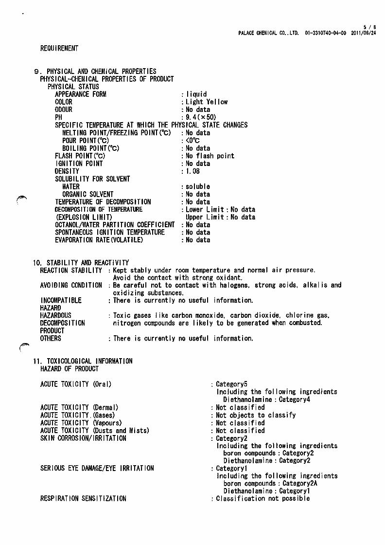
9. PHYSICAL AND CHEMICAL PROPERTIES PHYSICAL-CHEMICAL PROPERTIES OF PRODUCT
PHYSICAL STATUS APPEARANCE FORM : I i qu i d
5/8 PALACE CHEMICAL CO .. LTD. 01-3310740-04-00 2011/06/24
COLOR : Light Yellow ODOUR : No data PH : 9.4 (x 50) SPECIFIC TEMPERATURE AT WHICH THE PHYSICAL STATE CHANGES
MELTING POINT/FREEZING POINT(OC) : No data POUR POINT(OC) : (O°C BOILING POINT(°C) : No data
FLASH POINT(Oc) : No flash point IGNITION POINT : No data DENSITY : 1.08 SOLUBILITY FOR SOLVENT
WATER ORGANIC SOLVENT
TEMPERATURE OF DECOMPOSITION DECOMPOSITION OF TEMPERATURE (EXPLOSION LIMIT) OCTANOL/WATER PARTITION COEFFICIENT SPONTANEOUS IGNITION TEMPERATURE EVAPORATION RATE(VOLATILE)
10. STABILITY AND REACTIVITY
: soluble : No data : No data : Lower Limit: No data
Upper Li mit : No data : No data : No data : No data
REACTION STABILITY : Kept stably under room temperature and normal air pressure. Avoid the contact with strong oxidant.
AVOIDING CONDITION : Be careful not to contact with halogens. strong acids. alkal is and oxidizing substances.
INCOMPATIBLE HAZARD HAZARDOUS DECOMPOSITION PRODUCT OTHERS
: There is current I y no usefu I i nformat ion.
: Toxic gases I ike carbon monoxide. carbon dioxide. chlorine gas, nitrogen compounds are likely to be generated when combusted.
: There is currently no useful information.
11. TOXICOLOGICAL INFORMATION HAZARD OF PRODUCT
ACUTE TOXICITY (Oral)
ACUTE TOXICITY (Dermal) ACUTE TOXICITY. (Gases) ACUTE TOXICITY (Vapours) ACUTE TOXICITY (Dusts and Mists) SKIN CORROSION/IRRITATION
SERIOUS EYE DAMAGE/EYE IRRITATION
RESPIRATION SENSITIZATION
: Category5 Including the fol lowing ingredients
D i ethano I am i ne : Category4 : Not c I ass if i ed : Not objects to classify : Not classified : Not classified : Category2
Including the following ingredients boron oompounds : Category2 o i ethano I am i ne : Category2
: Category1 Including the following ingredients
boron compounds : Category2A D i ethano I am i ne : Categoryl
: Classification not possible

SKIN SENSITIZATION GERM CELL MUTAGENICITY CARCINOGENICITY REPRODUCTIVE TOXICITY
EFFECTS ON LACTATION SPECIFIC TARGET ORGAN TOXICITY SINGLE EXPOSURE
SPECIFIC TARGET ORGAN TOXICITY REPEATED EXPOSURE
ASPIRATION HAZARD
12. ECOLOGICAL INFORMATION
HAZARD OF PRODUCT TOXICITY PERSISTENCE AND DEGRADABILITY BIOACCUMULATIVE POTENTIAL MOBILITY IN SOIL
13. DISPOSAL CONSIDERATION
: No data : No data : No data : No data
6/8 PALACE CHEMICAL CO .. LTD. 01-3310740-04-00 2011/06/24
: Category1 : Classification not possible : Classification not possible : Category2
Including the fol lowing ingredients boron compounds: Category2
: Classification not possible : Category1 (kidney. I iver. nervous system.
respiratory system) Including the fol lowing ingredients
boron compounds : Category1 (k i dney. nervous system. respiratory system) Diethanolamine : Category1 (I iver) Category3(esthesia action)
: Category1 (kidney. nervous system. respiratory system) Category2(liver.blood. testis. central nervous system) Including the following ingredients
boron compounds: Categoryl (k idney. nervous system. respiratory system) Category2 (testi s) D i ethano I am i ne : Category2 (I i ver . blood. central nervous system)
: Classification not possible
RESIDUAL WASTE : Do not release used water for cleansing into ground or drain. Burn in accordance with the industrial waste processing standards. Companies should dispose of the industrial waste by itself. or subcontracting to industrial waste processing companies certified by state government. or local public body. No dumping. Dispose of by using incineration system. and ensure each parameter of the cinder is under the standards specified by "Enforcement of Waste Disposal and Publ ic Cleaning Law", Burn in a safe place with precautions that avoid harm or damage from burning or explosions. and assign watchmen at the same time. Avoid inhaling smoke when fighting fire for the burning gas contains toxic gases such as carbon monoxide. carbon dioxide. sulfur oxides. nitrogen compounds and others.
14. TRANSPORT INFORMATION
INTERNATIONAL REGULATIONS: Air Transport according to lATA regulations Maritime transport according to IMDG regulations
NATIONAL ACTS AND : It falls under the following restrictions on the transportation REGULATIONS of domestic act. each container in accordance with the provisions

LAND MARINE
AVIATION UN classification UN IDENTIFICATION NUMBER NOTES
SPECIFIC SAFETY MEASURES AND CONDITIONS FOR TRANSPORT
15. REGULATORY INFORMATION
7 I 8 PALACE CHEMICAL CO .. LTD. 01-3310740-04-00 2011/06/24
of the Act, the manner of transport : the Fire and Disaster Management Act Nonhazardous Material : Ship Safety Act Nonhazardous Material In a separate transport
and bulk transport : Civi I Aeronautics Act Nonhazardous Material : Not fallen within any of UN classes : None : Ensure there is no leakage, collapse, falling or damage when
embarking. Do not mix with 1st or 6th class of hazardous materials, or high pressure gases(some exceptions). Add MIC certified sign on the vehicle and instal I appropriate fire extinguisher when transporting the product in quantities more than specified. Ensure the container won't col I ide or sway significantly when transport i ng. Add a sign on the vehicle and instal I appropriate fire extinguisher when transporting the hazardous materials in quantities more than specified. Stack less than 3m from ground when transporting.
: Before transporting, make sure the container has no damage, corrosion or leakage. Load with care so that there's no turning over, fal ling down or any damages, and make sure that there'll be no col lapses. Package, display and transfer in accordance with appl icable laws. Flammable!
Industrial Safety and Health Act(Article 57-2) Deliver of Documents
: Corresponding
Industrial Safety and Health Act (Article 57) Labe ling Poisonous and Deleterious Substances Control Law Ordinance on Prevention of Organic Solvent Poisoning Ordinance on Prevention of Hazards Due to Specified Chemical Substances Act on Confirmation, etc. of Release Amounts of Specific Chemical Substances in the Environment and Promotion of Improvements to the Management Thereof Act on the Evaluation of Chemical Substances and Regulation of Their Manufacture, etc. the Fire and Disaster Management Act Waste Management and Public Cleansing Law
Water Pollution Control Law
16. OTHER INFORMATION Reference
• MSDS of raw materials
RESPONSE SECTION FOR ABOVE INFORMATION
: Not app I i cab I e
: Not app I i cab I e
: Not app I i cab I e
: Not app I i cab I e
: Not app I i cab I e
: Not app I i cab I e
: Not app I i cab I e : Industrial waste regulations(Spread,
ban) : Cor respond i ng
Please inquire of section of "1. Identification".
runoff

8 1 B PALACE CHEMICAL CO .. LTD. 01-3310740-04-00 2011/06/24
This product safety data sheet is based on the material information. Therefore~ it is sometimes revised by'the new knowledge. When you treat this product, consult this data sheet and try to do accord i ng to the actua I state under the respons i b iii ty for you. This data sheet is not the guarantee of the safety and the quality. This MSDS is made on the basis of the Japanese law.
- The end -

Issue date: Nov.101l2010 Revision date:
SDS-C-80SE (U-BOND WR-7HA Hardener) 1/5
SAFETY DATA SHEET 1. CHEMICAL PRODUCT _ CO~ ANY IDENTIFICATION
CHEMICAL PRODUCT NAME : U-BOND WR-7HA Hardener
NAME OF MANUFACTURER/SUPPLIER: NIKKA SEIKO CO., LTD.
ADDRESS: 2-2-1, Nozawa, Setagaya-ku, Tokyo 154-0003 Japan
TELEPHONElFAXNo. : 81-3-3424-1811/81-3-3424-2882
EMAll.. ADDRESS: [email protected]
EMERGENCY PHONE NUMBER: 81-3-3424-1811
SDS No.: C-805E
2. HAZARD IDENTIFICA nON
GHS CLASSIFICA nON: PHYSICAL HAZARDS: Self.beating substances and mixtures
Substances and mixtures corrosive to metals HEALTH HAZARDS: Acute toxicity (Oral)
Acute toxicity (Dermal) Acute toxicity (Inhalation: vapor) Acute toxicity (Inhalation: dust/mist) Skin corrosion/irritation Severe eye damage/irritation Respiratory sensitization Skin sensitization Germ cell mutagenicity Carcinogenicity Reproductive toxicity Effects on or via lactation Specific target organ toxicity (Single exposure) Specific target organ toxicity (Repeated exposure)
Aspiration hazard ENVIRONMENTAL Hazardous to the aquatic environment (acute toxicity)
HAZARDS:
Classification not possible Classification not possible Category 5 Classification not possible Classification not possible Classification not possible Category 3 Category I Classification not possible Category 1 Classification not possible Classification not possible Classification not possible Classification not possible Classification not possible Category 1 Lung: InbaIation Classification not possible Classification not possible
Hazardous to the aquatic environment (chronic toxicity) Classification not possible <Other hazards except the above-described hazards are not applicable or not possible for the GHS classification.>
GHS LABEL ELEMENTS HAZARD PICTOGRAMS OR HAZARD SYMBOLS:
~~~ SIGNAL WORDS: Danger
Hazard statement codes: May be harmful if swallowed. Causes mild skin irritation. Causes serious eye damage. May cause allergic skin reaction. Causes damage to organs through prolonged or repeated exposure.
NIKKA SEIKO CO., LTD.
Liver, Thyroid gland
101015

Issue date: Nov.101l2010 Revision date:
SDS-C-80SE (U-BOND WR-7HA Hardener) 2/5
Prevention precautions: Do not eat, drink or smoke when using this product. Do not breathe dust/fume/mist/vaporslspray. Use only outdoors or in a well-ventilated area. Wear protective gloves/eye protection/face protection. Contaminated work clothing should not be allowed out of the workplace. Wash hands thoroughly after handling.
Response precautions: IF ON SKIN: Wash with plenty of soap and water. If skin irritation or rash OCCUIS: Take medical advice/treatment Take off contaminated clothing and wash before reuse. IF INHALED: Remove victim to fresh air and keep at rest in a position comfortable for breathing. IF IN EYES: Rinse cautiously with water for several minutes. Remove contact lenses if present and easy to do. Continue rinsing. If feeling unwell, take medical advice/treatment.
Storage precautions: Protect from sunlight and wetting. Store locked up.
Disposal precautions: Ask dispose of contents/container to industrial waste treatment agent which is permitted by regional government.
3. COMPOSITION I INFORMATION ON INGREDIENTS
SUBSTANCEIMIXTURE: Mixture
PRODUCT DESCRIPTION: Epoxy resin two-component liquid adhesive (Hardener)
INGREDIENTS AND COMPOSmON :
INGREDIENT
Aliphatic polythiol
Amine compound
m-Xylylenediamine (MXDA)
Phenol derivative
4. FIRST-AID MEASURES
PROPORTION
<1%
CASNo.
Registered
Registered
1477-55-0
Registered
INHALA nON: !fthe vapor generated by the reaction with the resin is inhaled and there are any symptoms of itchiness, etc., immediately remove the victim from the contaminated to fresh air area. Take ~ medical advice.
SKIN CONTACT: Immediately wipe out and wash with soap and warm water. Do not use solvent or thinner.If there are symptoms of itchness or skin inflammation, take medical advice immediately.
EYE CONTACT: Immediately rinse the eyes with plenty of water. Ifremoving is diificult or any itchiness or inflammation is felt, take medical advice immediately.
INGESTION: Immediately rinse mouth with water well. Then give the person plenty of water or milk. If possible, induce vomiting but not necessary to induce vomiting by force. Take medical advice immediately. Do not give an unconscious person anything to drink.
5. FIRE-FIGHTING MEASURES
EXTINGUISIflNG MEDIA: Foam, Dry chemical powder, Carbon dioxide, Dry sand.
INAPPROPRIATE EXTINGUISIflNG MEDIA: Do not use solid water stream directly (May cause fire-spreading).
UNUSUAL FIRE AND EXPLOSION HAZARDS: Avoid inhalation of the smoke as it may generate toxic sulfur oxides and nitrogen oxides.
NIKKA SEIKO CO., LTD. 101015
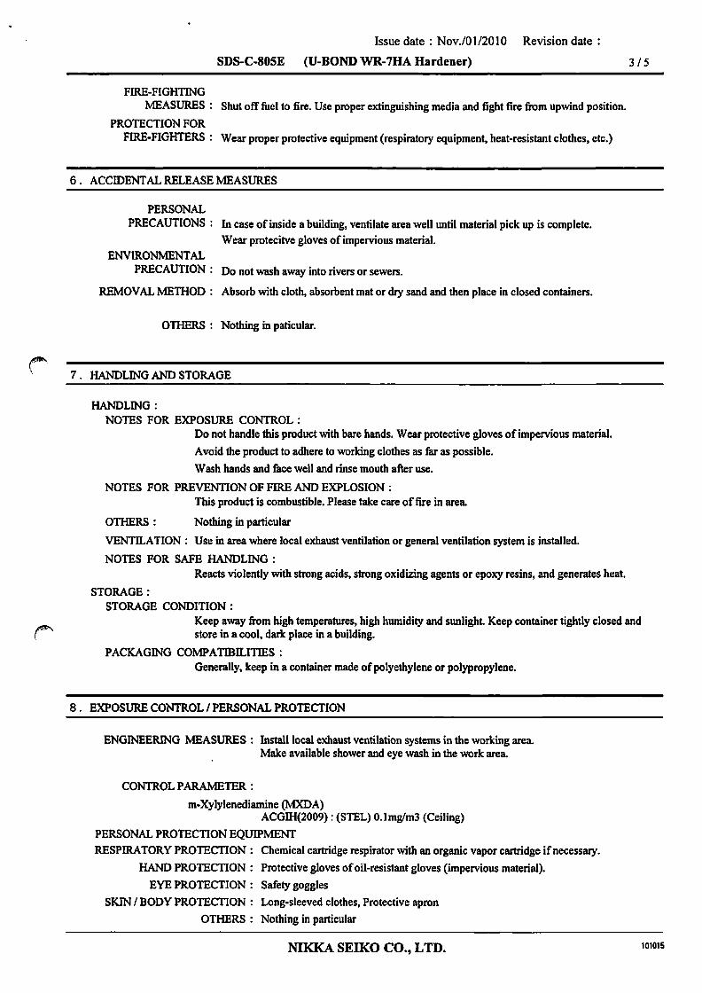
Issue date: Nov.101l201O Revision date:
SDS-C-80SE (U-BOND WR-7HA Hardener) 3/5
FIRE-FIGHTING MEASURES: Shut off fuel to fire. Use proper extinguishing media and fight fire from upwind position.
PROTECTION FOR FIRE-FIGHTERS: Wear proper protective equipment (respiratory equipment, heat-resistant clothes, etc.)
6. ACCIDENTAL RELEASE MEASURES
PERSONAL PRECAUTIONS: In case of inside a building, ventilate area well until material pick up is complete.
Wear protecitve gloves of impervious material. ENVIRONMENTAL
PRECAUTION: Do not wash away into rivers or sewers.
REMOVAL METHOD: Absorb with cloth, absorbent mat or dry sand and then place in closed containers.
OTHERS: Nothing in paticular.
7. HANDLING AND STORAGE
HANDLING: NOTES FOR EXPOSURE CONTROL:
Do not handle this product with bare hands. Wear protective gloves of impervious material.
Avoid the product to adhere to working clothes as far as possible.
Wash hands and face well and rinse mouth after use.
NOTES FOR PREVENTION OF FIRE AND EXPLOSION: This product is combustible. Please take care of fire in area.
OTHERS : Nothing in particular
VENTILATION: Use in area where local exhaust ventilation or general ventilation system is installed.
NOTES FOR SAFE HANDLING: Reacts violently with strong acids, strong oxidizing agents or epoxy resins, and generates heat.
STORAGE: STORAGE CONDITION:
Keep away from high temperatures, high humidity and sunlight Keep container tightly closed and store in a cool, dark place in a building.
PACKAGING COMPATIBll.ITIES : Generally. keep in a container made of polyethylene or polypropylene.
8. EXPOSURE CONTROL I PERSONAL PROTECTION
ENGINEERING MEASURES: Install local exhaust ventilation systems in the working area. Make available shower and eye wash in the work area.
CONTROLPARAMETER:
m-Xylylenediamine (MXDA) ACGllI(2009): (STEL) O.lmglm3 (Ceiling)
PERSONAL PROTECTION EQUIPMENT RESPIRATORY PROTECTION: Chemical cartridge respirator with an organic vapor cartridge if necessary.
HAND PROTECTION: Protective gloves of oil-resistant gloves (impervious material).
EYE PROTECTION: Safety goggles
SKIN I BODY PROTECTION: Long-sleeved clothes, Protective apron
OTHERS: Nothing in particular
NIKKA SEIKO CO., LTD. 101015

Issue date: NovJ01l2010 Revision date:
SDS-C-80SE (U-BOND WR-7HA Hardener) 4/5
9. PHYSICAL AND CHEMICAL PROPERTIES
APPEARANCE, PHYSICAL STATE I FORM: Paste
COLOR: Light yellow - Light brown clear
ODOR: Not evaluated
pH: Not applicable
MELTING POINT: No data
INITIAL BOILING POINT AND BOILING RANGE: No data
FLASHING POINT: > 122t (Cleveland Open Cup)
AUTOIGNITION TEMPERATURE: No data
FLAMMABILITY (SOLID, GAS): Not applicable
EXPLOSION LIMIT: No data
VAPOR PRESSURE: No data
VAPOR DENSITY: No data
EVAPORATIONRATE: Nodata
SPECIFIC GRAVITY(H2O=I): 1.12(25"C)
SOLUBILITY: Insoluble in water.
OCT ANOL I WATER PARTITION COEFFICIENT: m-Xylylenediamine: log Pow 0.18
DECOMPOSmON TEMPERATURE: No data
OTHERS: Nothing in particular
1 O. STABILITY AND REACTIVITY
STABILITY: Stable.
REACTIVITY: Reacts violently with strong acids, strong oxidizing agents or epoxy resins and may generate heat.
CONDITIONS TO AVOID: Unknown
MATERIALS TO AVOID: Avoid contact with strong acids, strong oxidizing agents, epoxy resins.
HAZARDOUS DECOMPOSITION
PRODUCTS: Mercaptans, Organic sulfieds, Hydrogen sulfide, Sulfur oxides, Nitrogen oxides, etc.
OTHERS: Nothing in particular
1 1. TOXICOLOGICAL INFORMATION
Acute toxicity (Oral)
Category 5 May be harmful if swallowed.
Category 5 Phenol derivative
Aliphatic polythiol
Skin corrosion/irritation
Category 3 Causes mild skin irritation.
Category 2 Phenol derivative
Severe eye damage/irritation
Category 1 Causes serious eye damage.
Category I Phenol derivative
NIKKA SEIKO CO., LTD.
(rat) LD50 4000mglkg
(rat) LD50 2600mg/L
fromNITE
fromNITE
101015

Issue date: Nov.lOl/2010 Revision date:
SDS-C-80SE (V-BOND WR-7HA Hardener) 5 /5
Skin sensitization
Category 1 May cause allergic skin reaction.
Category I Phenol derivative
Specific target organ toxicity (Repeated exposure)
Category 1 Causes damage to organs through prolonged or repeated exposure.
Category I Phenol derivative
1 2. ECOLOGICAL INFORMATION
GHS CLASSIFICATION
fromNITE
fromNITE
ENVIRONMENTAL HAZARDS : Classification is not possible, not applicable or exempted due to insufficient data.
OTHERS : Nothing in particular
1 3. DISPOSAL CONSIDERATION
~ Ask Industrial waste treatment agent for proper waste disposal. Follow all regulations in your country.
1 4. TRANSPORT INFORMATION
UN CLASS: Not applicable
UN No.: Not applicable
Proper Shipping Name: Not applicable
Packing Group: Not applicable
Marine Polutant: Not applicable
Handle with care. Keep away from heat or sunlight. Follow all regulations in your country.
15. REGURATORYINFORMATION
Follow aU regulations in your country.
~ 16. OTHER INFORMATION
REFERENCES: 1) International Chemical Sefety Cards (ICSC) 2) GHS Classification result and Classification reason, National Institute of Technology and Evaluation in Japan (NITE),
Ingredient Information 3) Epoxy Resin and Hardener Safe Handling Guide. (The Japan Society of Epoxy Resin Technology.)
The information herein is given in good faith,but no warranty,express or implied, is made. Please consult NIKKA SEIKO CO.,L TO. for further information.
This MSDS is translated from Japanese into English, which information is in accordance with Japanese laws and regulations.
NIKKA SEIKO CO., LTD. 101015
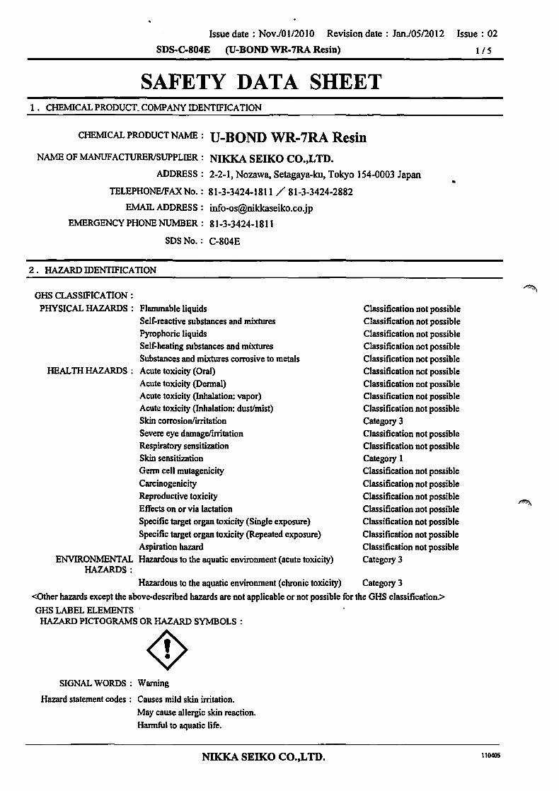
Issue date: Nov.101l201O Revision date: Jan.lOS/2012 Issue: 02
SDS-C-804E (U-BOND WR-7RA Resin) 115
SAFETY DATA SHEET 1. CHEMICAL PRODUCT_ COMPANY IDENTIFICATION
CHEMICAL PRODUCT NAME : U-BOND WR-7RA Resin
NAME OF MANUFACTURERlSUPPLffiR: NIKKA SEIKO CO.,LTD.
ADDRESS: 2-2-1, Nozawa, Setagaya-ku, Tokyo 154-0003 Japan
TELEPHONEIFAXNo.: 81-3-3424-1811 /81-3-3424-2882 ..
EMAIL ADDRESS:[email protected]
EMERGENCY PHONE NUMBER: 81-3-3424-1811
SDS No.: C-804E
2. HAZARD IDENTIFICATION
GHS CLASSIFICATION: PHYSICAL HAZARDS: Flammable liquids
Self-reactive substances and mixtures Pyrophoric liquids Self-beating substances and mixtures Substances and mixtures corrosive to metals
HEALTH HAZARDS: Acute toxicity (Oral) Acute toxicity (Dermal) Acute toxicity (Inhalation: vapor) Acute toxicity (Inhalation: dust/mist) Skin corrosion/irritation Severe eye damage/irritation Respiratory sensitization Skin sensitization Germ cell mutagenicity Carcinogenicity Reproductive toxicity Effects on or via lactation Specific target organ toxicity (Single exposure) Specific target organ toxicity (Repeated exposure) Aspiration hazard
ENVIRONMENTAL Hazardous to the aquatic environment (acute toxicity) HAZARDS:
Hazardous to the aquatic environment (chronic toxicity)
Classification not possible Classification not possible Classification not possible Classification not possible Classification not possible Classification not possible Classification not possible Classification not possible Classification not possible Category 3 Classification not possible Classification not possible Category I Classification not possible Classification not possible Classification Dot possible Classification Dot possible Classification not possible Classification not possible Classification not possible Category 3
Category 3
<Other hazards except the above-described hazards are not applicable or not possible for the GHS classification.>
GHS LABEL ELEMENTS HAZARD PICTOGRAMS OR HAZARD SYMBOLS:
~ SIGNAL WORDS: Warning
Hazard statement codes: Causes mild skin irritation. May cause allergic skin reaction. Harmful to aquatic life.
NIKKA SEIKO CO.,L TD. 110405

Issue date: Nov.101l201O Revision date: Jan.105/2012 Issue: 02
SDS-C-804E (V-BOND WR-7RA Resin) 2/5
Hannful to aquatic life with long lasting effects.
Prevention precautions: Do not breathe dust/fume/mist/vapors/spray. Wear protective gloves/eye protection/face protection. Contaminated work clothing should not be allowed out of the workplace. Wash hands thoroughly after handling. Avoid release to the environment.
Response precautions: IF ON SKIN: Wash with plenty of soap and water. If skin irritation or rash occurs: Take medical advice/treatment. Take off contaminated clothing and wash before reuse. IF IN EYES: Rinse cautiously with water for several minutes. Remove contact lenses if present and easy to do. Continue rinsing. If eye irritation persists: Take medical advice/treatment.
Storage precautions: Protect from sunlight and wetting. Store locked up.
Disposal precautions: Ask dispose of contents/container to industrial waste treatment agent which is permitted by regional government.
3. COMPOSITION / INFORMATION ON INGREDIENTS
SUBSTANCEIMIXTURE: Mixture
PRODUCT DESCRIPTION: Epoxy resin two-component liquid adhesive (Resin)
INGREDIENTS AND COMPOSITION:
INGREDIENT
Bisphenol A type-epoxy resin
Other epoxy resin
Silica
Filler
Coloring agent (Blue)
4. FIRST -AID MEASURES
PROPORTION CAS No.
25068-38-6
Registered 10%-20% 7631-86-9
Registered
Registered
INHALATION: If the vapor generated by the reaction with the hardener is inhaled and there are symptoms of itchiness. etc .• remove the victim to ftesh air area immediately. Take medical advice immediately.
SKIN CONTACT: Immediately wipe out and wash with soap and warm water. Do not use solvent or thinner.If there are symptoms ofitchness or skin inflammation. take medical advice immediately.
EYE CONTACT: Immediately rinse the eyes with clean water for at least 15 min. If any pain is felt. take medical advice immediately.
INGESTION: If possible. give the person plenty of water or milk to induce vomiting. But not necessary to induce by force. Take medical treatment immediately. Do not give unconscious person anything to drink.
5. FIRE-FIGHTING MEASURES
EXTINGUISHING MEDIA: Foam, Dry chemical powder. Carbon dioxide, Dry sand.
INAPPROPRIATE EXTINGUISHING MEDIA: Do not use solid water stream directly (May cause fire-spreading).
UNUSUAL FIRE AND EXPLOSION HAZARDS: Wear proper respiratory protective equipment because toxic gas (carbon monoxide. etc.) may
be generated on fire.
NIKKA SEIKO CO.,LTD. 110405

Issue date: Nov.lOl/2010 Revision date: Jan.lOS12012 Issue: 02
SDS-C-804E (U-BOND WR-7RA Resin)
FIRE-FIGHTING MEASURES: Shut otIfuel to fire. Use proper extinguishing media and fight fire from upwind position.
PROTECTION FOR FIRE-FIGHTERS: Wear proper protective equipment (respiratory equipment, heat-resistant clothes, etc.)
6. ACCIDENTAL RELEASE MEASURES
PERSONAL PRECAUTIONS: In case of inside a building, ventilate area well until material pick up is complete.
Wear protective gloves of impervious material. ENVIRONMENTAL
PRECAUTION: Do not wash away into rivers or sewers.
REMOVAL METHOD: Absorb with cloth, absorbent mat or dry sand and then place in closed containers.
OTHERS: Nothing in particular
7. HANDLING AND STORAGE
HANDLING: NOTES FOR EXPOSURE CONTROL:
Do not handle this product with bare bands. Wear protective gloves of impervious material.
A void the product to adhere to working clothes as far as possible.
Wash hands and face well and rinse mouth after use.
NOTES FOR PREVENTION OF FIRE AND EXPLOSION: This product is combustible. Please take care of fire in area.
OTHERS: Nothing in particular
VENTll.ATION : Use in area where local exhaust ventilation or general ventilation system is installed.
NOTES FOR SAFE HANDLING: Do not mix with strong oxidizing agents, strong acids or strong bases.
STORAGE: STORAGE CONDITION:
Keep away from sunlight Store in a building.Keep container tightly closed. Store at room temperature. Do not store at temperatures below lOt.
PACKAGING COMPA TIBll..ITIES : Generally. keep in a container made of polyethylene or polypropylene.
8. EXPOSURE CONTROL / PERSONAL PROTECTION
ENGINEERING MEASURES : Install local exhaust ventilation systems in the working area. Make available shower and eye wash in the work area.
CONTROLPARAMETER:
ACGllI(2009): Not established
PERSONAL PROTECTION EQUIPMENT RESPIRATORY PROTECTION: Chemical cartridge respirator with an organic vapor cartridge if necessary.
HAND PROTECTION: Protective gloves of oil-resistant type (impervious material).
EYE PROTECTION: Safety goggles
SKIN / BODY PROTECTION: Long-sleeved clothes, Protective apron
OTHERS: Nothing in particular
NIKKA SEIKO CO.,LTD.
3/5
110405
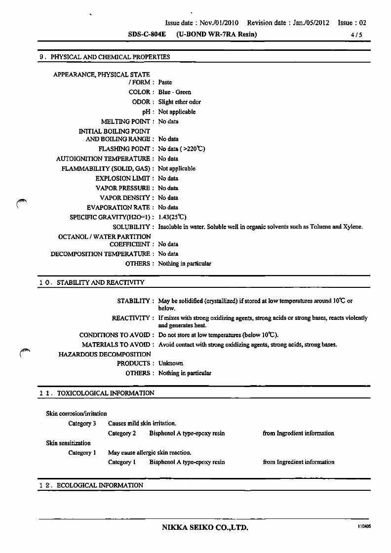
Issue date: Nov.101l2010 Revision date: Jan.l05/2012 Issue: 02
SDS-C-804E (U-BOND WR-7RA Resin) 415
9. PHYSICAL AND CHEMICAL PROPERTIES
APPEARANCE, PHYSICAL STATE 1 FORM: Paste
COLOR: Blue - Green
ODOR: Slight ether odor
pH: Not applicable
MELTING POINT: No data
INIT1AL BOll.ING POINT AND BOll.ING RANGE: No data
FLASHING POINT: No data ( >220t)
AUTOIGNITION TEMPERATURE: No data
FLAMMABll.ITY (SOLID, GAS): Not applicable
EXPLOSION LIMIT: No data
VAPOR PRESSURE: No data
VAPOR DENSITY: No data
EVAPORATION RATE: No data
SPECIFIC ORA VITY(H20= 1): 1.43(2St)
SOLUBILITY: Insoluble in water. Soluble well in organic solvents such as Toluene and Xylene.
OCTANOL I WATER PARTITION COEFFICIENT: No data
DECOMPOSITION TEMPERATURE: No data
OTHERS: Nothing in particular
1 O. STABILITY AND REACTMTY
STABILITY: May be solidified (crystallized) if stored at low temperatures around lOt or below.
REACTMTY: If mixes with strong oxidizing agents, strong acids or strong bases, reacts violently and generates heat.
CONDITIONS TO AVOID: Do not store at low temperatures (below lOt).
MATERIALS TO AVOID: Avoid contact with strong oxidizing agents, strong acids, strong bases.
~ HAZARDOUS DECOMPOSITION
PRODUCTS: Unknown
OTHERS: Nothing in particular
1 1. TOXICOLOGICAL INFORMATION
Skin corrosion/irritation
Category 3
Skin sensitization
Category I
Causes mild skin irritation.
Category 2 Bisphenol A type-epoxy resin
May cause allergic skin reaction.
Category 1 Bisphenol A type-epoxy resin
1 2. ECOLOGICAL INFORMATION
NIKKA SEIKO CO.,LTD.
from Ingredient infonnation
from Ingredient infonnation
110405

Issue date: Nov.101l2010 Revision date: Jan.lOS/2012 Issue: 02
SDS-C-804E (V-BOND WR-7RA Resin) 5 IS
Hazardous to the aquatic environment (acute toxicity)
Category 3 Hannful to aquatic life.
Category 2 Bisphenol A type-epoxy resin
Hazardous to the aquatic environment (chronic toxicity)
Category 3 Hannful to aquatic life with long lasting effects.
Category 2 Bisphenol A type-epoxy resin
OTHERS : Nothing in particular
1 3. DISPOSAL CONSIDERATION
Crustacea (Daphnia Magna) ECSO(48hr) 1.7mgIL
from Ingredient infonnation
Ask Industrial waste treatment agent for proper waste disposal. Follow all regulations in your counby.
1 4. TRANSPORT lNFORMA TION
UN CLASS: Not applicable
UN No.: Not applicable
Proper Shipping Name: Not applicable
Packing Group: Not applicable
Marine Pollutant: Not applicable
Handle with care. Keep away from heat or sunlight. Follow all regulations in your counby.
1 5. REGURA TORY lNFORMA TION
Follow all regulations in your counby.
1 6. OTHER INFORMATION
REFERENCES: 1) International Chemical Sefety Cards (lCSC) 2) GHS Classification result and Classification reason. National Institute of Technology and Evaluation in Japan (NITE).
Ingredient Information ~
3) Epoxy Resin and Hardener Safe Handling Guide. (The Japan Society of Epoxy Resin Technology.)
The infonnation herein is given in good faith.but no warranty, express or implied, is made. Please consult NIKKA SEIKO CO.,L TD. for further infonnation.
This MSDS is translated from Japanese into English, which infonnation is in accordance with Japanese laws and regulations.
NIKKA SEIKO CO.,LTD. 1\0405
Issue date: Apr.l27/2011 Revision date: Issue: 01
SDS-D-418E (SOLBLUE B) 1/6
SAFETY DATA SHEET 1. CHEMICAL PRODUCT. COMPANY IDENTIFICATION
CHEMICAL PRODUCT NAME: SOLBL UE B
NAME OF MANUFACTURER/SUPPLIER: NIKKA SEIKO CO.,LTD.
ADDRESS: 2-2-1. Nozawa. Setagaya-ku. Tokyo 154-0003 Japan
TELEPHONElFAXNo. : 81-3-3424-1811 /81-3-3424-2882
EMAIL ADDRESS:[email protected]
EMERGENCY PHONE NUMBER: 81-3-3424-1811
SDS No.: D-418E
2. HAZARD IDENTIFICATION
GHS CLASSIFICATION: PHYSICAL HAZARDS: Self-heating substances and mixtures
Substances and mixtures corrosive to metals HEALTH HAZARDS: Acute toxicity (Oral)
Acute toxicity (Dennal) Acute toxicity (Inhalation: vapor) Acute toxicity (Inhalation: dust/mist) Skin corrosion/irritation Severe eye damage/irritation Respiratory sensitization Skin sensitization Germ cell mutagenicity Carcinogenicity Reproductive toxicity Effects on or via lactation Specific target organ toxicity (Single exposure)
Specific target organ toxicity (Repeated exposure)
Classification not possible Classification not possible Category 5 Classification not possible Classification not possible Classification not possible Category 2 Category 2 Classification not possible Classification not possible Classification not possible Classification not possible Category 2 Classification not possible Category 3 Respiratory tract irritation Category 1 Bone marrow. Spleen. Liver. Respiratory organ. Adrenal gland, Kidney
Aspiration hazard ENVIRONMENTAL Hazardous to the aquatic environment (acute toxicity)
HAZARDS:
Classification not possible Classification not possible
Hazardous to the aquatic environment (chronic toxicity) Classification not possible
<Other hazards except the above-described hazards are not applicable or not possible for the GHS classification.>
GHS LABEL ELEMENTS HAZARD PICTOGRAMS OR HAZARD SYMBOLS:
SIGNAL WORDS: Danger
Hazard statement codes: May be harmful if swallowed. Causes skin irritation. Causes serious eye irritation.
NIKKA SEIKO CO.,LTD. llD405

Issue date: Apr.l27/2011 Revision date:
SDS-D-418E (SOLBLUE B)
Issue: 01
2/6
Suspected of damaging fertility or the unborn child. (Respiratory tract irritation) May cause respiratory irritation. Causes damage to organs through prolonged or repeated exposure.
Bone marrow, Spleen, Liver, Respiratory organ, Adrenal gland, Kidney
Prevention precautions: Obtain special insbuctions before use. Do not handle until all safety precautions have been read and understood. Do not eat, drink or smoke when using this product. Do not breathe mist/vapors/spray. Use only outdoors or in a well-ventilated area. Wear protective gloves/eye protection/face protection. Wash hands thoroughly after handling.
Response precautions: IF INHALED: Remove victim to fresh air and keep at rest in a position comfortable for breathing. IF ON SKIN: Wash with plenty of soap and water. If skin irritation occurs: Take medical advice/treatment. Wash contaminated clothing before reuse. IF IN EYES: Rinse cautiously with water for several minutes. Remove contact lenses if present and easy to do. Continue rinsing. If eye irritation persists: Take medical adviceltreatment. If exposed or concerned: Take medical advice/treatment. IF SWALLOWED: Immediately take medical adviceltreatment. Do not induce vomiting.
Storage precautions: Store in a closed container, in a cool I well-ventilated place. Store locked up.
Disposal precautions: Ask dispose of contents/container to industrial waste treatment agent which is pennitted by regional government.
3. COMPOSmON I INFORMATION ON INGREDIENTS
SUBSTANCEIMIXTURE: Mixture
PRODUCT DESCRIPTION: Resin removing agent
INGREDIENTS AND COMPOSITION:
INGREDIENT
Amide type solvent
Alcohol type solvent
4. FIRST -AID MEASURES
PROPORTION CAS No.
Registered
Registered
INHALATION: Remove the person to fresh air area immediately. Cover the body with blanket to keep warm and quiet. Ifbreathing has stopped or is weak, loosen the clothes and administer artifical respiration. Immediately take medical treatment.
SKIN CONTACT: Immediately rinse with plenty of water, then wash with soap well.
EYE CONTACT: Immediately rinse the eyes with clean water for at least IS min. (If easily possible, remove contact lenses). Take medical advice.Rinse well by opening eyelids wide.
INGESTION: Rinse the mouth with water well. Do not induce vomiting as this may increase the risk of aspiration of the liquid into the lungs causing chemical pneumonitis. Take medical treatment immediately.
5. FIRE-FIGHTING MEASURES
NIKKA SEIKO CO.,LTD. 110405

Issue date: Apr.l2712011 Revision date:
SDS-D-418E (SOLBLUE B)
Issue: 01
3/6
EXTINGUISHING MEDIA: Alcohol-resistant (oam, Dry chemical powder. Carbon dioxide. Dry sand.
INAPPROPRIATE EXTINGUISHING MEDIA: Do not use solid water stream directly (May cause fire-spreading).
UNUSUAL FIRE AND EXPLOSION HAZARDS: Wear proper respiratory protective equipment because toxic gas (carbon monoxide. etc.) may
be generated on fire.
FIRE-FIGHTING MEASURES: Shut off fuel to fire. Use proper extinguishing media and fight fire from upwind position.
PROTECTION FOR FIRE-FIGHTERS: Wear proper respiratory protective equipment.
6. ACCIDENTAL RELEASE MEASURES
PERSONAL PRECAUTIONS: In case of inside a building. ventilate area well until material pick up is complete.
Wear protective gloves of impervious material and protective goggles. ENVlRONMENT AL
PRECAUTION: Do not wash away into rivers or sewers.
REMOVAL METHOD: In case of small spill. absorb with cloth. absorbent mat or dry sand and then place in closed containers.
In case of large spill. use inert material such as dry sand or earth to prevent the spill and lead it to safer area. Cover the surface with foam and place in closed containers.
OTHERS: Eliminate all sources of ignition in area. Use appropriate extinguishing media.
Use non-sparking handtools.
7. HANDLING AND STORAGE
HANDLING: NOTES FOR EXPOSURE CONTROL:
Wear proper protective equipment to avoid eye or skin contact.
Wash hands and face well and rinse mouth after use.
NOTES FOR PREVENTION OF FIRE AND EXPLOSION:
OTHERS :
Shut off all sources of ignition in area. Equipment should be grounded as static electricity counteraction. Electrical equipment system should have explosion-proof system. Use non-sparking handtools.
Nothing in particular
VENTILATION: Use in area where local exhaust ventilation or general ventilation system is installed.
NOTES FOR SAFE HANDLING: Do not mix with strong oxidizing agents.
STORAGE: STORAGE CONDITION:
Keep container tightly closed. Store in a well-ventilated, cool, dark place. Keep away from sunlight.Store away from strong oxidizing agents.
PACKAGING COMPATIBll.JTIES : Generally, keep in a container made of high density polyethylene.
8. EXPOSURE CONTROL 1 PERSONAL PROTECTION
ENGINEERING MEASURES: It is recommended to use a system which encloses vapor generated area. Or usc local
NIKKA SEIKO CO.,LTD. 110405
Issue date: Apr.l27/2011 Revision date: Issue: 01
SDS-D-418E (SOLBLUE B) 4/6
exhaust ventilation systems or general ventilation systems. Make available emergency shower and eye wash in the work area.
CONTROLPARAMETER:
Amide type solvent ACGIH(2009): Not established
PERSONAL PROTECTION EQUIPMENT
RESPIRATORY PROTECTION: Chemical cartridge respirator with an organic vapor cartridge if necessary.
HAND PROTECTION: Strong protective gloves of impervious material (polyethylene, Polypropylene, Neoprene, Silicone rubber only).
EYE PROTECTION: Safety goggles.
SKIN I BODY PROTECTION: Long-sleeved clothes, Protective apron
OTHERS: Nothing in particular
9. PHYSICAL AND CHEMICAL PROPERTIES
APPEARANCE, PHYSICAL STATE / FORM: Liquid
COLOR: Colorless - Light yellow clear
ODOR: Slight amine odor
pH: Not applicable
MELTING POINT: No data
INITIAL BOalNG POINT AND BOILING RANGE: 20S'C(Baiance reflux boiling point)
FLASHING POINT: 9S'C (Cleveland Open Cup)
AUTOIGNITION TEMPERATURE: No data
FLAJvfMABILITY (SOLID, GAS): Not applicable
EXPLOSION LIMIT: No data
VAPOR PRESSURE: No data
VAPOR DENSITY: No data
EVAPORATION RATE : Nodata
SPECIFIC GRA VITY(H2O=l): 1.04(2S'C)
SOLUBILITY: Soluble in water well.
OCTANOL/WATERPARTITION COEFFICIENT: No data
DECOMPOSITION TEMPERATURE: No data
OTHERS: Nothing in particular
1 o. STABD..ITY AND REACTIVITY
ST ABD..ITY: Stable
REACTMTY: Causes exothennal reaction by contacting with strong oxidizing agents, strong acids, strong alkali.
CONDmONS TO AVOID: Do not store at high temperatures.
MATERIALS TO AVOID: Do not mix with strong oxidizing agents, strong bases, strong acids.
HAZARDOUS DECOMPOSITION
PRODUCTS: When heated or burned, toxic fumes containing carbon monoxide. nitrogen oxide may be generated.
OTHERS: Nothing in particular
1 1. TOXICOLOGICAL INFORMA nON
NIKKA SEIKO CO.,LTD. 110405
Issue date: Apr.l27/2011 Revision date: Issue: 01
SDS-D-418E (SOLBLUE B) 5/6
Acute toxicity (Oral)
Category 5 May be harmful if swallowed.
Skin corrosion/irritation
Category 4
Category 5
Alcohol type solvent
Amide type solvent
Category 2 Causes skin irritation.
Category 2 Amide type solvent
Severe eye damage/irritation
Category 2 Causes serious eye irritation.
Category 2A Amide type solvent
Reproductive toxicity
Category 2 Suspected of damaging fertility or the unborn child.
Category 2 Amide type solvent
Specific target organ toxicity (Single exposure)
Category 3 (Respiratory tract irritation) May cause respiratory irritation.
Category 3 Amide type solvent
Specific target organ toxicity (Repeated exposure)
Category 1 Causes damage to organs through prolonged or repeated exposure.
Category 1 Amide type solvent
1 2. ECOLOGICAL INFORMATION
GHS CLASSIFICATION
(rat) LD50 1230mg/kg
(rat) LD50 4150mg/kg
from Ingredient information
from Ingredient information
from Ingredient information
from Ingredient information
from Ingredient information
ENVIRONMENTAL HAZARDS : Classification is not possible, not applicable or exempted due to insufficient data.
OTHERS : Nothing in particular
1 3. DISPOSAL CONSIDERATION
Ask Industrial waste treatment agent for proper waste disposal. Follow all regulations in your country.
1 4. TRANSPORT INFORMATION
UN CLASS: Not applicable
UN No.: Not applicable
Proper Shipping Name: Not applicable
Packing Group: Not applicable
Marine Polutant: Not applicable
Handle with care. Keep away from heat or sunlight. Follow all regulations in your country.
1 5. REGURATORY INFORMATION
Follow all regulations in your country.
1 6. OTHER INFORMATION
REFERENCES:
NIKKA SEIKO CO.,LTD. 110405

Issue date : Apr.l27/20 11 Revision date :
SDS-D-418E (SOLBLUE B)
1) International Chemical Sefety Cards (ICSe)
Issue: 01
6/6
2) GHS Classification result and Classification reason, National Institute of Technology and Evaluation in Japan (NITE), Ingredient Information
The infonnation herein is given in good faith,but no warranty,express or implied. is made. Please consult NIKKA SEIKO CO.,L ro. for further infonnation.
This MSDS is translated from Japanese into English, which infonnation is in accordance with Japanese laws and regulations.
NIKKA SEIKO CO.,L TD. 110405

14'1
14. Operation Manual Table of Contents 14-1. Outline ............................................................................................... 3
14 -I-I. Operation Outline ........................................................................ 3
14-2. Initial Operation ................................................................................ 4
14 -2-1. Operation Procedure .................................................................... 4
14-3. Operation Panel ................................................................................. 5
14-3-1. Main Operation Panel .................................................................. 5
14-3-2. Touch Panel Initial Display .......................................................... 5
14-4. Descriptions of Touch Panel Operation Display .................................. 9
14-4-1. Main Display ................................................................................ 9
14-4-2.Monitor Display .......................................................................... 14
14-4-3. Setting Display ........................................................................... 18
14-4'3'1. Common Switches for Setting Display ............................................ 18
14-4'3'2. Setting Display - Wire Run ........................................................... 22
14-4-3-3. Setting Display - Up and Down ................................................ _ .... 23
14-4-3-4. Setting - Rocking .......................................................................... 25
14-4'3-5. Setting - Stage Setting Display ..................................................... 26
14-4-3'6. Setting - AXIS Y SETTING/EQUAL PITCH MODE(Option) .......... 29
14-4-3-7. Setting - AXIS Y SETTING/FREE PITCH(Option) ........................ 31
14-4-3-8. Setting - AXIS e SETTING(Option) ............................................... 32
14-4-4. Alarm Display ......................................................................... 33
14-4-5. Reel Coiling Setting Display ....................................................... 34
14-4-6. Manual Display ................................................................................... 36
14-4-6-1-1. Reel Display ............................................................................... 40
14-4-6-2. Traverser Display .......................................................................... 44
14-4-6-3. Tensioner Display ......................................................................... 46
14-4-6-4. Up and Down Display .................................................................... 47
14-4-6-5. Rocking Display ............................................................................ 51
14-4-6-6. AXIS Y Display(Option) ................................................................. 53

14-2
14-4-6-7. AXIS Y EQUAL PITCH Display(Option) ........................................ 55
14-4-6-8. AXIS Y FREE PITCH Display(Option).. ......................................... 56
14-4-6-9. AXIS e Display(Option) .......... _ ............................................. 57
14-4-7. Process Data Select Display ....................................................... 59
14-4-8. Common Data ..................................................... _ ........ _ ............. 61
14-4-9. Maintenance Data Display ......................................................... 62
14-4-10. Engineer Data Display ............................................................. 64
14-4-11. Time Setting Display ........... _ ................................ _ ................... 65
14-4-12. Tool Display ............................................................................. 66
14'4-13. File Manager ..................................................................................... 80
14-4-14. Password Manager Display ................................................................ 81
14-4-15. Language Display ....................... _ ............................................. 84
14-4-16. Power OFF Display .................................................................. 85
14'4'17. Setting List .............................................................................. 88
14-5.Error ................................................................................................. 91
14-5-1.ErrorMessage .............................................................................. 91
14'6. Replacing battery ............................................................................ 108
14'6'1. Replacing servo battery procedure ............................................. 108
14-6'2. Replacing the stepping battery .................................................. 110
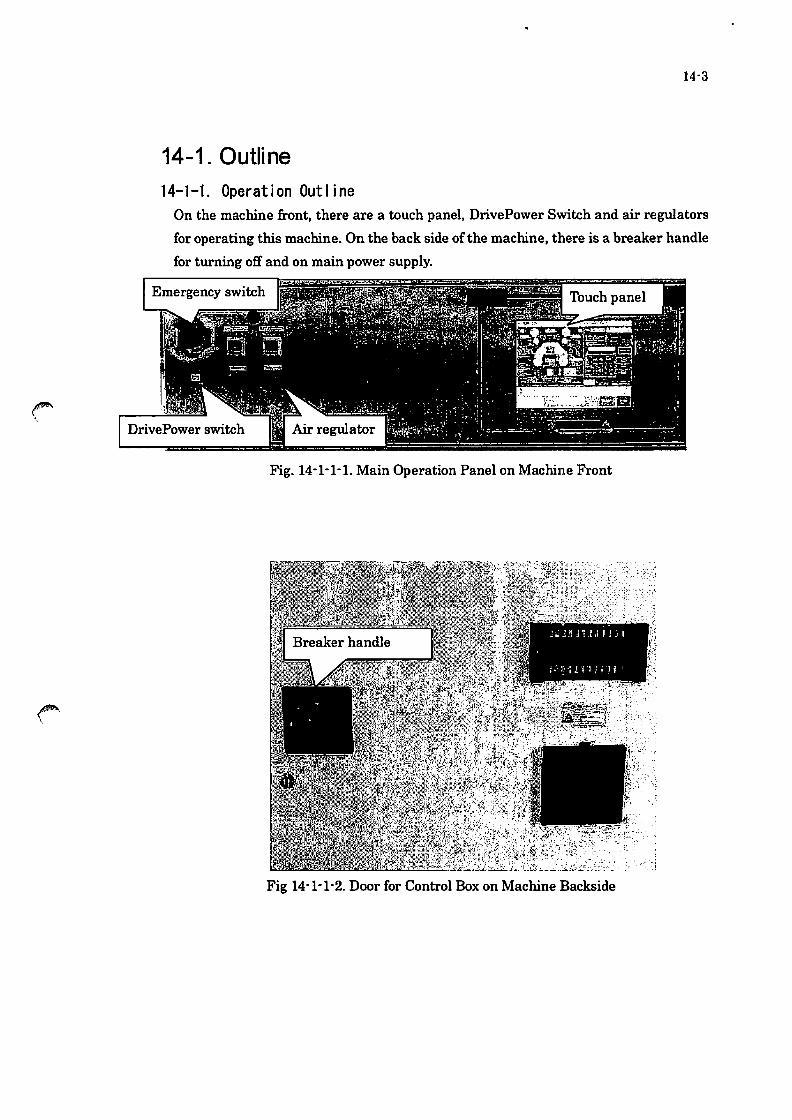
14-3
14-1. Outline 14-1-1. Operation Outline
On the machine front, there are a touch panel, DrivePower Switch and air regulators
for operating this machine. On the back side of the machine, there is a breaker handle
for turning off' and on main power supply_
Fig. 14-1-1-1. Main Operation Panel on Machine Front
Fig 14-1-1-2. Door for Control Box on Machine Backside

14-2. Initial Operation 14-2-1. Operation Procedure
Operate the machine safely following the procedure as below.
(1) Always perform safety check before starting operation
(2) Check the safety inside and around the machine.
14'4
(3) Turn the breaker handle on the center of the left door of the control box to start
main power supply.
(4) Press the servo' on switch on the main operation panel.
(5) See the monitor and check the system has finished the start operation.
(6) Continue operation.

14-3. Operation Panel 14-3-1. Main Operation Panel
There is the main operation panel on the machine front side.
1. Drive Power
14'5
This is a servo-on switch and always need to be pressed to start power supply to the
servo motor drivers after turning the breaker handle for main power supply on the
control box.
2. Air regulator
This switch is for adjusting the air pressure.
3. Touch panel
All operation is performed through this touch panel.
14-3-2. Touch Panel Initial Display Touch panel display shows the picture as Fig 14-3-2-1 when it is powered on.
Fig 14'3'2'1 Initial Display
The Initial Display shown in Fig 14-3-2-1 appears while reading the system settings.
Leave the monitor until the display changes automatically.

14-6
Fig. 14-3-2-2 Initial Display
When this picture appears, touch the center of the display to move the next display.
If touching the center of the display, the display changes to Fig. 14-3-2-3 Menu
Display.
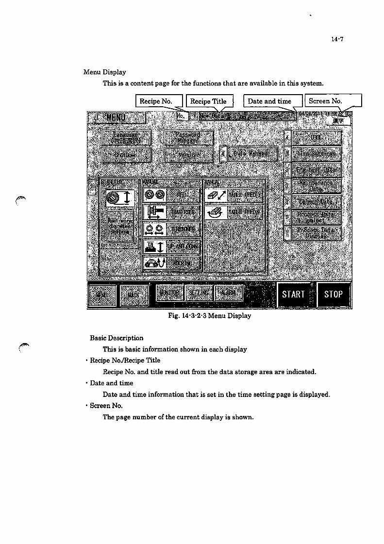
Menu Display
This is a content page for the functions that are available in this system.
Fig. 14-3-2-3 Menu Display
Basic Description
This is basic information shown in each display
• Recipe NoJRecipe Title
Recipe No. and title read out from the data storage area are indicated.
• Date and time
Date and time information that is set in the time setting page is displayed.
• Screen No.
The page number of the current display is shown.
14-7

14-8
Basic Operation Switch
o Menu - move to the menu page
o Main - move to the main page_
o Monitor - move to the monitor page
o Setting - move to the setting page
o Alarm - move to the alarm page
o START - start auto operation, the title of the switch turns to "Running" while auto
running and the light of the switch turns on_
o STOP - stop operation
Functional Switch o Language Selection------- Thuch the switch when selecting the language
o PowerOFF-------Thuch the switch when turning OFF the Device
o Version-------Indicate the software version
o Password Manager-------Set the password security level
* The switches with numbers from rn to rn are available with password input_
o List Selection-------Show the setting value list indication
o Recipe Selection------Read and duplicate the registered recipe (processing condition)
o Common Data-------Set the basic settings ofthe device
o Maintenance Data-----Set the maintenance settings of the materials
o Engineering Data-- -----Set the important movement of the device
o Time-------Set the date and time
o Thol------Use for calibration ofthe device
o File Manager------Upgrade the software and save the recipe data
o Stand by------Prepare for the operation
o MANUAL------ Manual operation of the unit

14-4. Descriptions of Touch Panel Operation Display
14-4-1. Main Display
Fig 14-4-1-1.Main Display
This display is for starting/stopping auto operation .
• When the machine is operating,
AUTO· • • Auto running is selected .
14-9
• Each operation of the three modes as below will start according to the condition setting.
If pressing STOP beside the start switch, each operation will stop. When "Processing"
turns on, start operation is not available.
Wll'e Run Start
Rocking Auto Start
* Travers Start/Stop function operates simultaneously with the wire run.

14-10
• Outward Stop
If pressing this switch during wire running, the operation stops when outward
running finishes.
• Outward Pause
Ifpressing this switch during wire running, the operation stops temporarily
when outward running finishes.
(When "Processing" turns on, this operation is not feasible.>
• Return Stop
Ifpressing this switch during wire running, the operation stops when return
running finishes.
• Return Pause
Ifpressing this switch during wire running, the operation stops temporarily
when return running finishes.
(When "Processing" turns on, this operation is not feasible.>
• Without Auto Remove
Set enable/disable wire removal after finishing slicing.
• Tension Control Off
Shows on/off state of the tension control
Setting on/off of the tension control is available in the preparation page.
• "Processing"
"Processing"lamp turns on when the auto slicing starts and until the slicing
movement finishes or stops.
• Process Reset
This switch is used to suspend the slicing. If touching this switch, the
confirmation window will pop up.

14-11
• Mode Switch
The window of Fig 14-4-1-2_ appears if pressing the mode switch. ,
Fig 14-4-1-2. Operation Mode Pop Up Window
CD ALONEILINK· • • Select the reel movement. Set "LINK" Wlder normal
operation.
® Reciprocate· • • Reciprocate the wire running under the specified condition.
@ Supply Direction· • • r - J : Reel L-R
r-J : ReeIR-L
® Select the mode of wire rWlning from constant speed mode, step mode and
consecutive mode (*1)
® Select the mode of the up and down movement from constant speed mode,
step mode and consecutive mode (*1).
® Select the mode of the rocking movement from constant speed mode, step
mode and consecutive mode (*1) .
• Please see the next page for the description for *1.

14-12
(* 1) Constant Speed Mode, Step Mode and Consecutive Mode
• Constant Speed Mode: Slicing speed is constant from the slicing start position to
the end position according to the speed set in the process condition page .
• STEPMODE : The elevating unit moves from slicing start position to the end
position in the speeds set in the stage setting page. The moving speed
changes step-likely according to the speed set in the each stage .
• CONSECUTIVE MODE: The elevating unit moves from slicing start position to
the end position in the speeds set in the stage setting page. The moving
speed changes linearly according to the speed set in the each stage.
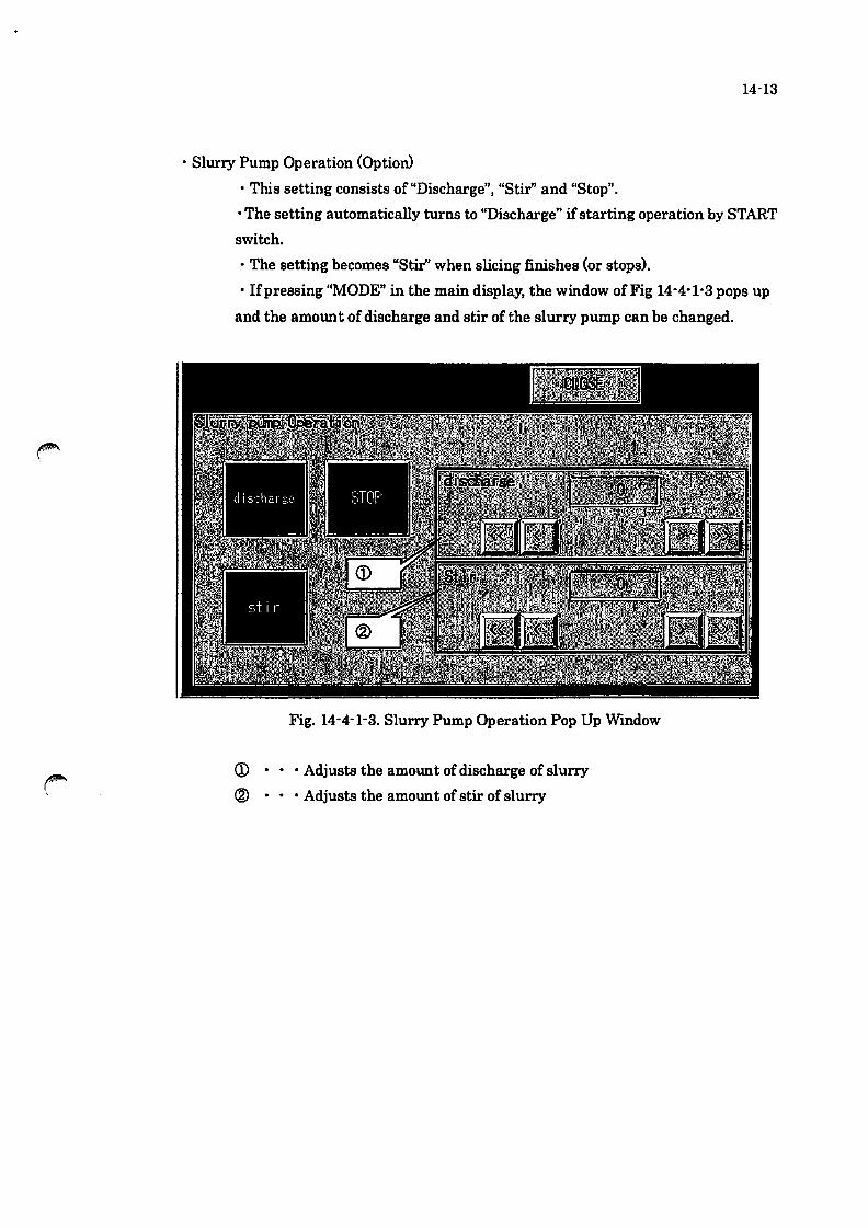
14-13
• Slurry Pump Operation (Option)
• This setting consists of "Discharge", "Stir" and "Stop"_
• The setting automatically turns to "Discharge" if starting operation by START
switch_
• The setting becomes "Stir" when slicing finishes (or stops).
• If pressing "MODE" in the main display, the window of Fig 14-4-1-3 pops up
and the amount of discharge and stir of the slurry pump can be changed_
Fig. 14-4-1-3. Slurry Pump Operation Pop Up Wmdow
CD • • • Adjusts the amount of discharge of slurry
® • Adjusts the amount of stir of slurry

14-4-2. Monitor Display
If i g h1: all:.owd _ of I~ur'l ~nt ('UI): 1_. I
)It t Illg ! ho <i_01l1l'" "=:1-1 CJ .::t; t l I tI ~ t 11I~)' ..... - •
r"l-u"t\E~"S L\lEC;i : I"'"
Fig. 14-4-2-11.~oDdtor
This page shows the current operation condition.
The items pointed by the numbers in the balloons are described as follow.
14-14

(1) Reel Part ... Please see the enlarged view in the Fig 14-4-2-2
Fig. 14-4-2-2. Enlarged view of the monitor display (1) in Fig. 14-4-2-1
CD · • • L reel, wire length
® · · • R reel, wire length
@ · • • Wire used length
@ • Wire supplying direction
@ · • • Traverse L position
® • Traverse R position
(J) · · • Tensioner L angle
® • Tensioner R angle
(2) Wire running condition set values
Those values shows currently selected command values.
(3) Rocking unit
Fig 14-4-2-3 Enlarged view ofthe monitor display (3) in Fig. 14-4-2-1
CD ••• Rocking angle monitor
® ... Rocking speed monitor
(4) Wire running speed monitor
Monitor the wire running speed.
14-15

(5) Up and down unit· • • Refer to enlarged view shown in Fig 14-4-2-4.
Fig. 14-4-2-4. Enlarged view of the monitor display (5) in Fig. 14-4-2-1
CD • • • Up and down height monitor
® . . . Up and down speed monitor
(6) Pump unit (option) • • • Refer to enlarged view shown in Fig 14-4-2-5.
Fig. 14-4-2-5. Enlarged view ofthe monitor display (6) in Fig. 14-4-2-1
CD • • • Discharge and slurry stirring indication lamp
® • . . Coolant pump speed monitor
(7) Wire usage total value
Display the wire usage total value.
(8) Wire usage total value clear switch
Press this switch longer when clearing the wire usage total value.
(9) Cutting monitor
14'16
Fig. 14-4-2-6. Enlarged view of the monitor display (9) in Fig. 14'4'2'1
CD • Cutting the amount of current (mm) monitor
® ... Cutting the amount setting (mm)
® ... Progress rate (%) monitor
(10) Processing indication lamp
The processing indication lamp flashes during processing operation.
(11) Elapsed time
Display the elapsed time.
(12) Bow recovering wait time
Display the bow recovering wait time.

(13) Graph
If pressing "Graph", a graph pops up as in the fig 14'4'2'7.
Fig. 14'4-2-7. Graph display in monitor display
(14) Alarm/message box
Display the alarm/message.
(15) Y unit monitor (option)
The monitor for the Y unit.
(16) e unit monitor (option)
The monitor for the e unit.
14'17

14-18
14-4-3. Setting Display • In the setting display. different kinds of process condition can be set.
14-4-3-1. Common Switches for Setting Display
Fig. 14-4-3-1-1 Setting- Wll'e Run

(1) Input permit, recipe register and page switches
• Refer to enlarged view shown in Fig 14-4-3-1-2.
Fig 14-4-3-1-2.Common switches in the setting display
14-19
ill . . . Input permission switch: Parameter input in each page is available if
pressing this switch when the password level is 2 or higher.
® ... Recipe storage switch: Display the confirmation dialogue window shown
in Fig 14-4-3-1-3 if pressing this switch when the password level is 2 or
higher. Display the processing screen window shown in Fig 14-4-3-1-4 if
touch the OK screen button and then store the processing condition to the
recipe currently selected. When the complete screen window shown in Fig
14-4-3-1-5 appears, press OK screen button. This operation is completed
when the display disappears.
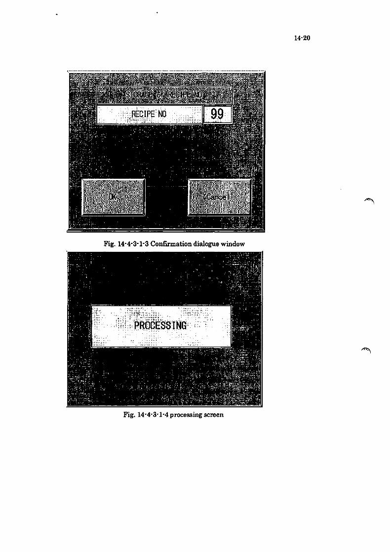
14-20
Fig. 14-4-3-1-3 Confirmation dialogue window
Fig. 14-4-3-1-4 processing screen

Fig, 14-4-3-1-5 Complete Screen
® . . . go to Setting Display - Wire Run
@ • • • go to Setting Display - Up and down
® . . . go to Setting Display - Rocking
@ • • • go to Setting Display - Stage Setting
(J) • • • go to Setting Display - Y Setting{Option)
® . . . go to Setting Display - e Setting{Option)
14-21

14-22
14-4-3-2. Setting Display - Wire Run
jgI 14-4-3-2. Setting Display - Wll'e Run
<D • Set the maximum speed of wire run in the auto mode
® . . • Set the time for the speed shifting from 0 to the set running speed in
wire reciprocation operation
® • Set the time from the acceleration ends until the deceleration starts
@ • • • Set the amount of new wire supply during wire run
@ • Set the wire run speed during wire automatic removal
® • Set the wire diameter
cr> ••• Set the moving amount of the reel traverse (1)
® . Set the moving amount of the reel traverse (R)

14-23
14-4-3-3. Setting Display - Up and Down
Fig. 14-4-3-3-1. Setting Display - Up and Down Display
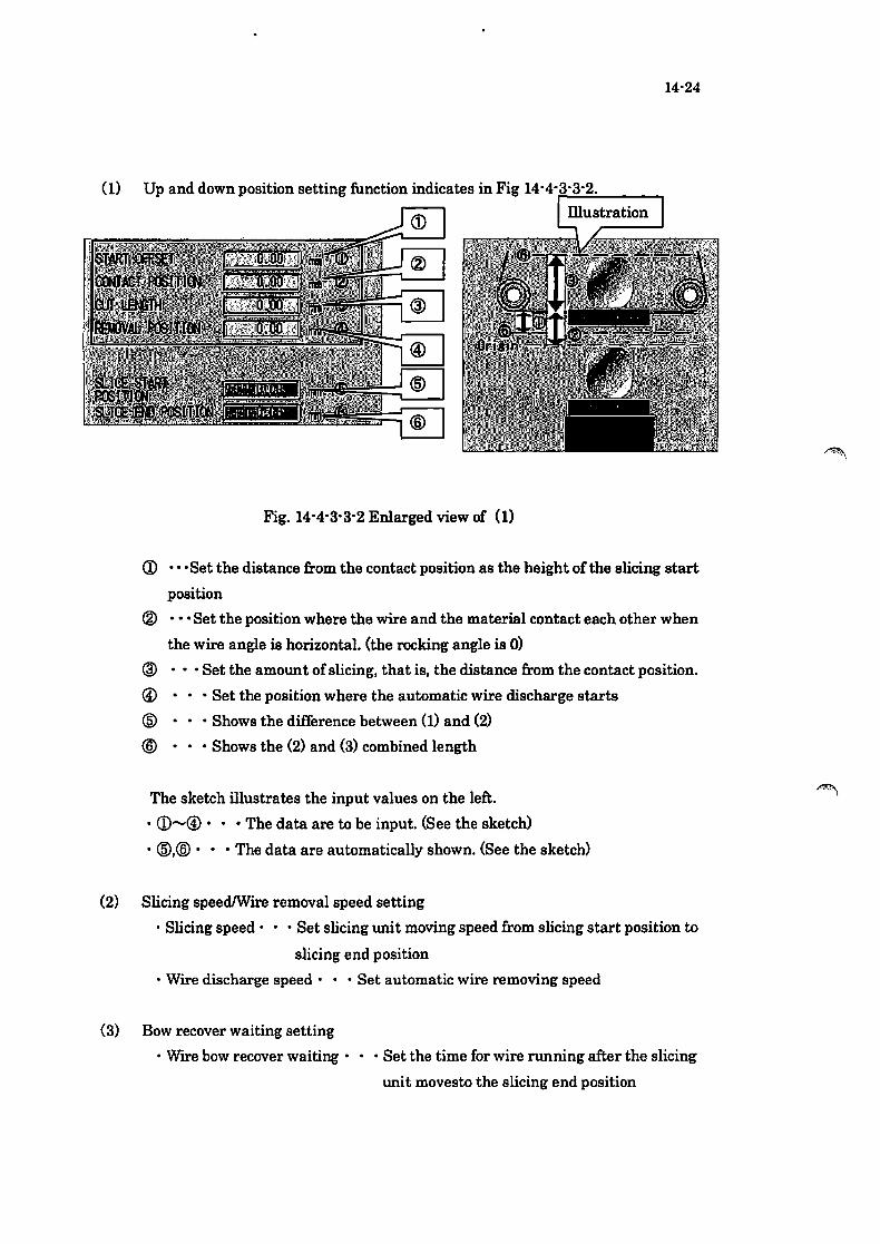
14-24
(1) Up and down position setting function indicates in Fig 14-4-r:-.:.:...:.;"--__ -,
Fig. 14-4-3-3-2 Enlarged view of (1)
Q) •• ·Set the distance from the contact position as the height of the slicing start
position
® _ •. Set the position where the wire and the material contact each other when
the wire angle is horizontal. (the rocking angle is 0)
® ... Set the amount of slicing, that is. the distance from the contact position.
@ • Set the position where the automatic wire discharge starts
@ • Shows the difference between (1) and (2)
@ • Shows the (2) and (3) combined length
The sketch illustrates the input values on the left .
• Q) ....... @. • • The data are to be input. (See the sketch>
• @.@. • • The data are automatically shown. (See the sketch>
(2) Slicing speedIWire removal speed setting
• Slicing speed· • • Set slicing uni t moving speed from slicing start position to
slicing end position
- Wlre discharge speed' • • Set automatic wire removing speed
(3) Bow recover waiting setting
. Wll'e bow recover waiting· • • Set the time for wire running after the slicing
unit movesto the slicing end position

14-25
14-4-3-4. Setting - Rocking
Fig. 14-4-3-4. Setting - Rocking
<D - Set the slicing unit rocking speed
® - Set the slicing unit rocking angle with + or - value based on the origin
point (horizontal).

14-26
14-4-3-5. Setting - Stage Setting Display
Fig 14-4-3-5-1_ Setting- Stage Setting 1-1
CD Stage Setting No_· • • Shows the number of stages (dividing the cut length
into the number of stages)
® Stage setting switchllamp ••• set the number of the stages from 1 to 25. The
numbers that are touched are set as the number of stages (number of
dividing)
® Up and down position data· • • Set slicing position in each stage that is set
in the stage setting switch
@ Process setting data· • • Set process data in each stage
® Paging· • • Move to the other setting page (running speed, acceleration and
deceleration, constant speed time, supplying amount) (Fig 14-4-3-5-2)
@ Paging· • • Move to the next page for the stage number 16 - 25_
CD Input Switch· • • Move to the stage position input page
(Fig 14-4-3-5-3)

14-27
Fig. 14-4-3-5-2. Setting - Stage Setting 2-1
Q) Stage setting data· • • show process data for each stage
® Stage setting lamp· • • lamp for stages that are set in Fig 14-4-3-5-1
@ Paging· • • Move to the other setting page <elevating position, elevating
speed, rocking angle, rocking speed) (Fig 14-4-3-5-1)
@ Paging··· Move to the page indicates 16 - 25 of corresponding pages as Fig
14-4-3-5-1.
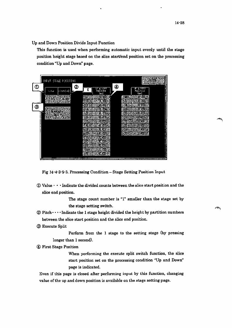
14-28
Up and Down Position Divide Input Function
This function is used when performing automatic input evenly until the stage
position height stage based on the slice start/end position set on the processing
condition "Up and Down" page.
Fig 14-4-3-5-3. Processing Condition - Stage Setting Position Input
CD Value· •• Indicate the divided counts between the slice start position and the
slice end position.
The stage count number is "1" smaller than the stage set by
the stage setting switch.
® Pitch· ••• Indicate the 1 stage height divided the height by partition numbers
between the slice start position and the slice end position.
@ Execute Split
Perform from the 1 stage to the setting stage (by pressing
longer than 1 second).
@ First Stage Position
When performing the execute split switch function, the slice
start position set on the processing condition ''Up and Down"
page is indicated.
Even if this page is closed after performing input by this function, changing
value of the up and down position is available on the stage setting page.

14-29
14-4-3-6. Setting - AXIS Y SETTING/EQUAL PITCH MODE(Option)
Fig. 14-4-3-6. Setting - AXIS Y SETTINGIEQUAL PITCH MODE
(j) • Set the wait position of axis Y
® • • • Set the rotation position of axis Y
@ • Set the auto low speed of axis Y r' @ • • • Set the auto high speed of axis Y ..
® • Set YI to the equal pitch mode
@ • Set Y2 to the equal pitch mode
<.V • Set YI to free pitch mode
® • • • Set Y2 to free pitch mode
® • Set the feeding standard position ofYI
@ • Set the pitch ofYI
@ • Set the number of feeding for YI
@ • • • Set the moving direction for YI @ • • • Show the maximum moving length ofYI
@ • Set the feeding standard position ofY2
@ • Set the pitch ofY2

14-30
@ • Set the number of feeding for Y2
@ ••• Set the moving direction ofY2
@ • Show the maximum moving length ofY2
@ ••• Move to the free pitch display

14-4-3-7. Setting - AXIS Y SETTING/FREE PITCH(Option)
Fig. 14-4'3-7. Setting-AXISY SETI'INGIFREE PITCH
CD ••• Set the number ofYl free pitch feeding
® .•• Set the amount ofYl free pitch feeding
@ • Set the number or Y2 free pitch feeding
@ ••• Set the amount ofY2 free pitch feeding
14-31

14-32
14-4-3-8. Setting - AXIS 8 SETTING(Option)
Fig. 14-4-3-8. Setting - AXIS 8 SE'TTING
CD • Set the 81 angle of AXIS 8
® . Set the 82 angle of AXIS 8
@ ••• Set the auto running speed of AXIS e

14-4-4. Alarm Display
Fig. 14-4-4. Alarm Display
CD • • • Time of occurrence
® . • • Time of reset (*shown only in the history page)
® . • . Error item
14-33
@) OccurrencelHistory tab· • • Occurrence page and History page can be
switched. Presently occurred alarm is shown in the occurrence page and the
alarm occurred in the past is shown in the history page.
® . . . turn off the Buzzer
@ • • • Reset the error status (alarm and warning etc)
(i) • • • Scroll the alarms

14-4-5. Reel Coiling Setting Display
Fig. 14-4-5-1. Standby Reel Diameter Setting
<D • • • turns on/off the left reel servo lock
® • turns on/off the right reel servo lock
@ • turns on/off the cylinder ofthe left tension pulley
@ • turns on/off the cYlinder of the right tension pulley
® . . . turns on/off the tension control
@ • • • turns on/off air purge of each part
CD • starts to measure the reel coil diameter, turns on while the
measurement is available.
® . . . press when stopping the measurement of the reel coil diameter
® . . . The measured values are automatically updated after each
measurement and this lamp turns on during the updating.
14-34

(10) Reel once winding operation
Fig. 14-4-5-2 Enlarged view of (10)
<D • Select the once winding operation.
® . • • Wind the reel once in reverse rotation.
@ • • • Wmd the reel once in normal rotation.
14'35
* Once winding operation is available when the "Manual" on the
"Manual Function Reel" page is lit.
(11) Reel winding manual setting
Fig. 14-4'5-3 Enlarged view of (11)
<D ••• Select the manual set value reflect.
® ... Set the L initial reel coil diameter 4>.
@ ••• Set the R initial reel coil diameter 4>.
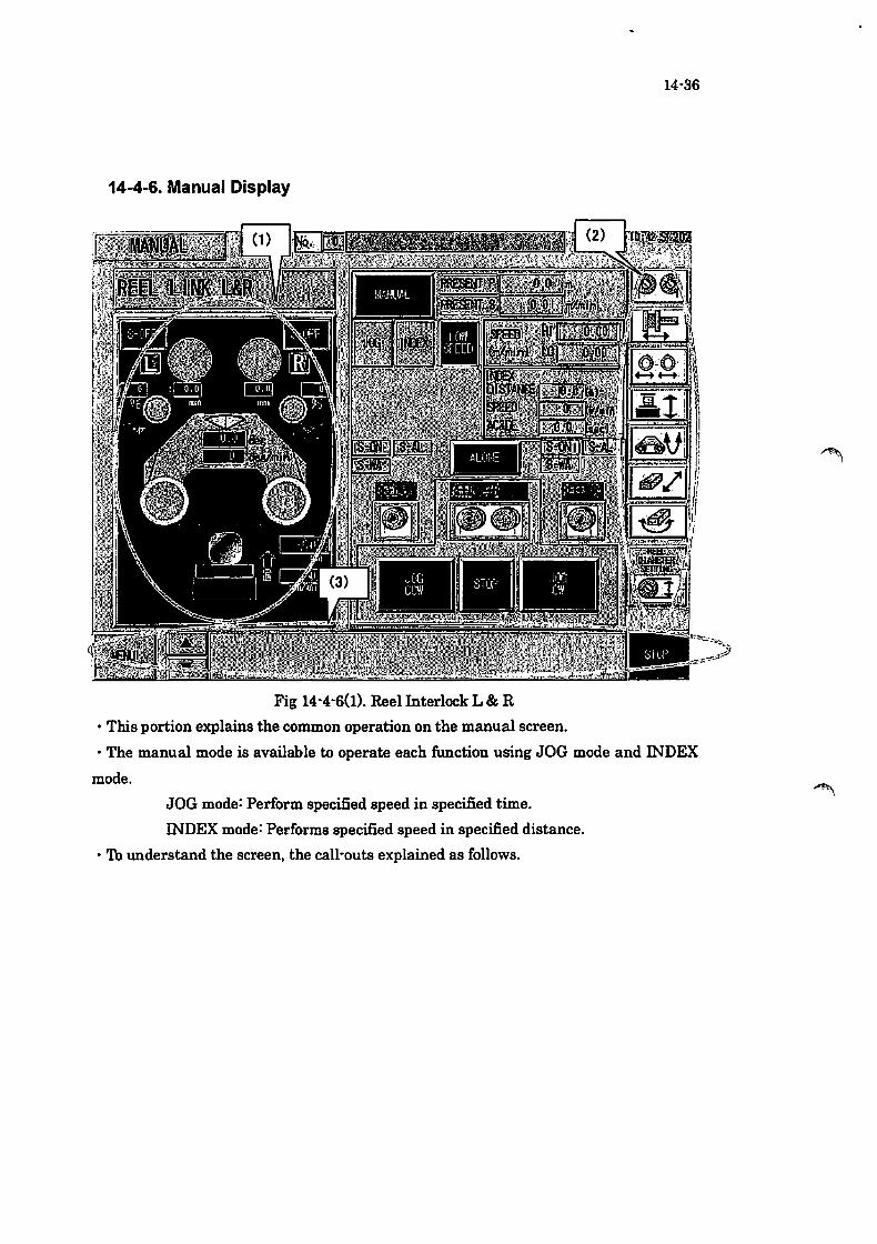
14-36
14-4-6. Manual Display
Fig 14-4-6(1). Reel Interlock L & R
• This portion explains the common operation on the manual screen.
• The manual mode is available to operate each function using JOG mode and INDEX
mode.
JOG mode: Perform specified speed in specified time.
INDEX mode: Performs specified speed in specified distance.
• To understand the screen, the call-outs explained as follows.

14-37
( I) Monitor part· •• Refer to enlarged view shown in Fig 14-4-6(2).
Fig 14-4-6(2) Manual screen common parts monitor part
CD • •• Reel Lservo ON/OFF switch
® • • • Reel R servo ON/OFF switch
® • • • Tensioner L present value
@ • Tensioner R present value
@ • • • Traverse L position
® • Traverse R position
(j) • •• Rocking angle monitor
® • Rocking speed monitor
® • Up and down level monitor
@ • • • Up and down speed monitor

14-38
( 2) Jumped page· • • Refer to enlarged view shown in Fig 14-4-6(3).
Fig. 14-4-6(3). Manual screen common parts jumped page
CD • jumps to the reel Land R unit
® . jumps to the traverser unit
® • jumps to the tensioner unit
@ • jumps to the up and down unit
® ... jumps to the rocking unit
® . jumps to the reel diameter setting page
(J) • jumps to the Y setting page(Option)
@ • jumps to the 8 setting page(Option)

14-39
(3) Contents, alarm and stop· •• Refer to enlarged view shown in Fig 14-4-6(4)
Fig. 14-4-6(4). Contents, alarm and stop
<D • jumps to the content page.
® ... shows presently occurred error. Up to three lines of the description can
be shown at a time.
® • . . All manual operation can be stopped with this switch.

14-4-6-1-1. Reel Display
Fig.14-4-6-l-I. Reel Link L&R
Operation related to manuaJ/reel is available
CD • • • switch the reel operation mode to manual
® . • • show the wire length run in the manual mode
@ • • • show the present speed of the wire running
@ • • • switch the reel operation to the JOG mode
® . . • switch the reel operation to the INDEX mode
@ • • • switch the speed between Hi and 10
r:JJ • switch the reel operation between alone and link
® . set highllow speed of each unit in the manual mode
14-40
® . . . set length, speed and acceleration and deceleration for INDEX mode.
@ • • • shows the status of the servo motor of the left reel. SoON means the
servo power is on, S-AL means servo alarm and S-WA means servo
warning.
@ • • • show the status of the servo motor of the right reel. SoON means the
14-41
servo power is on, S-AL means servo alarm and S-WA means servo
warning.
@ • • • moves to the manual display for left reel manual operation. (Fig.
14-4-6-1-2)
@ • • • moves to the manual display for the right reel manual operation (Fig.
14-4-6-1-3)
@ ••• starts reel operation in either JOG mode or INDEX mode. This switch
is for running wire from the right reel to the left reel.
@ • • • stops manual reel operation
@ ••• starts reel operation in either JOG mode or INDEX mode. This switch
is for running wire from the left reel to the right reel.

Reel Land R Alone Operation
Fig 14-4-6-1-2. Reel LAlone Display
• In the reel L alone display, the left reel can be operated separately. Basicaly, the
operation is the same as the reel link L&R operation.
14-42

Fig. 14-4-6-1-3. Reel RAlone Display
• In the reel R alone display, the left reel can be operated separately. Basicaly, the
operation is the same as the reel link L&R operation.
14-43

14-44
Fig. 14-4-6-2-1. Traverser L
. If pressing the traverser switch in the page jump part in the manual display, this
display opens. 'Ib move to the traverser R page, this traverser L page should be opened
first.
CD • switch traverser L operation to manual.
® . . . show the present position of traverser L
® • show the present speed of traverser L
@ • switch traverser L operation mode to JOG mode.
® . switch traverser L operation mode to INDEX mode
@ • show the condition ofthe servo motor oftraverser L, SoON means the
servo power is on, S-AL means servo alarm and S-WA means servo
warning.
(7) • • • switch the speed between Hi and Lo
® •.. set highllow speed of the unit in the manual mode
® • . • set the moving length in INDEX mode
@ • • • switch to traverser R page (Fig 14-4-6-2-2)
~ )
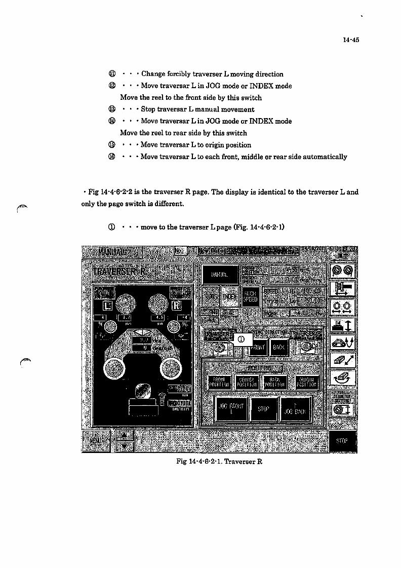
® . . . Change forcibly traverser L moving direction
@ • • • Move traversar L in JOG mode or INDEX mode
Move the reel to the front side by this switch
@ • • • Stop traversar L manual movement
@ • • • Move traversar L in JOG mode or INDEX mode
Move the reel to rear side by this switch
@ • • • Move traversar L to origin position
14-45
@ • • • Move traversar L to each front, middle or rear side automatically
• Fig 14-4-6-2-2 is the traverser R page. The display is identical to the traverser Land
only the page switch is different.
CD • • • move to the traverser L page (Fig. 14-4-6-2-0
Fig 14·4-6-2-1. Traverser R
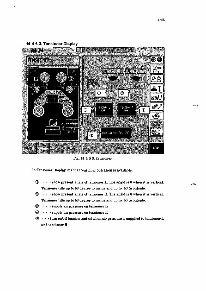
14-46
14-4-6-3. Tensioner Display
Fig. 14-4-6-3. Tensioner
In Tensioner Display, manual tensioner operation is available.
CD • • • show present angle of tensioner L. The angle is 0 when it is vertical.
Tensioner tilts up to 50 degree to inside and up to -50 to outside.
® ••• show present angle oftensioner R. The angle is 0 when it is vertical.
Tensioner tilts up to 50 degree to inside and up to -50 to outside.
@ • • • supply air pressure on tensioner L
@ • • • supply air pressure on tensioner R
® ..• turn on/off tension control when air pressure is supplied to tensioner L
and tensioner R
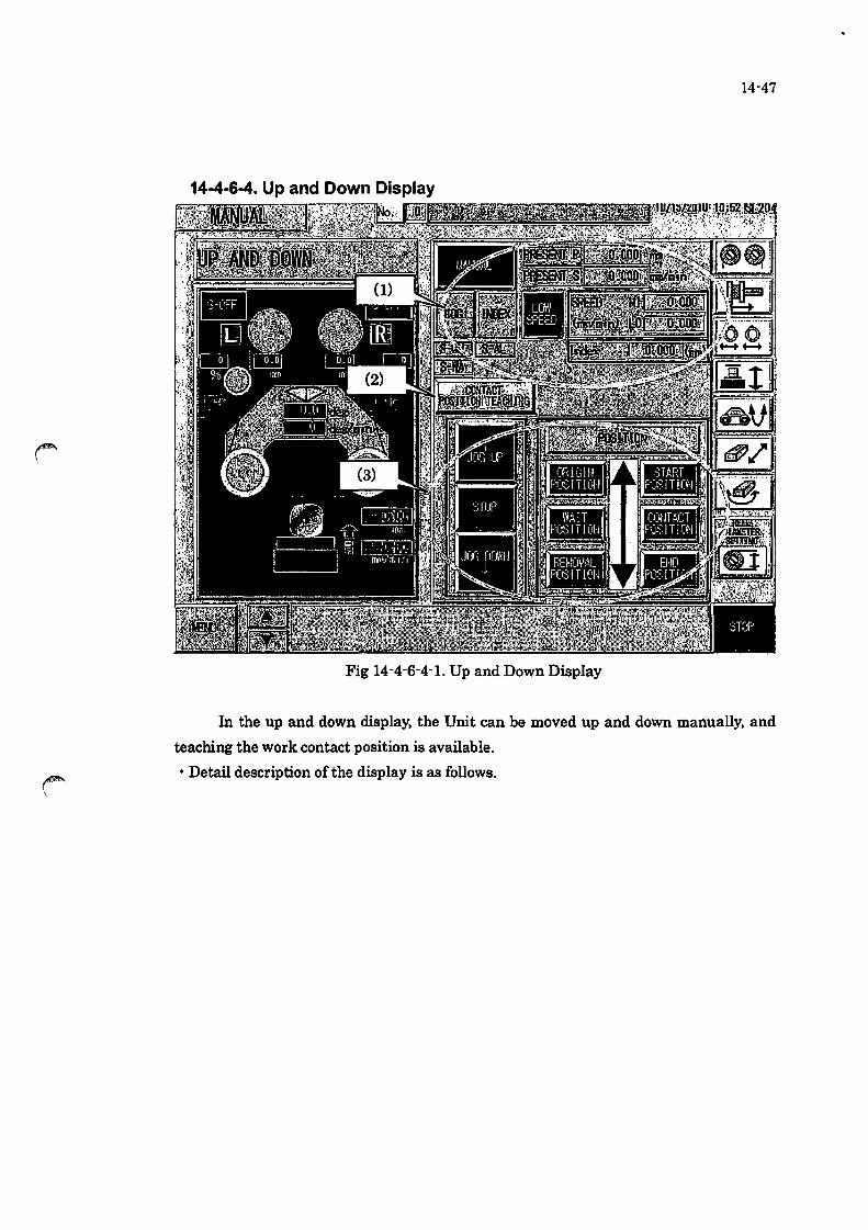
14-47
14-4·6-4. Up and Down Display
Fig 14-4-6-4-1. Up and Down Display
In the up and down display, the Unit can be moved up and down manually, and
teaching the work contact position is available_
• Detail description of the display is as follows_

(1) Mode Change and Data Setting
<D
Fig 14-4-6-4-2 (1) Enlarged View of Up and Down Display
<D ••• switch the up and down operation to manual
® ..• show the current position of up and down unit
@ ••• show the current speed of up and down unit
@ • • • switch the up and down operation to JOG mode
® • switch the up and down operation to INDEX mode
14-48
@ • show the status of the servo motor of the up and down unit. SoON
means the servo power is on, S-AL means servo alarm and S-WA means
servo warning.
cr> • switch the speed between high and low
@ ••• set the highllow speeds
® . . . set the moving length in INDEX mode

14-49
(2) Contact Position Teaching Switch
. If touching this button, the following display opens.
Fig 14-4-6-4-3 Contact Position Teaching Pop up Display
<D • • • show the present position of the up and down unit
® • . . setting of contact position is available by touching this button
@ • show presently set contact position of the up and down unit
r--\

14-50
(3) Manual Operation Switch
Fig 14-4-6-4-4_ Enlarged View (3) of Up and Down Display
CD • • • Perform JOG or INDEX operation in manual mode
Move the up and down unit upward by this switch
® • • • Stop the up and down unit manual movement
@ • •• Perform JOG or INDEX operation in manual mode
Move the up and down unit downward by this switch
@ • •• Move the up and down unit to the waiting position
Set by the processing condition - up and down
@ • • • Move the up and down unit to removal position
Set by the processing condition - up and down
® • •• Move the up and down unit the start position ~
Set by the processing condition - up and down
(J) • •• Move the up and down unit to the contact position
Set by the processing condition - up and down
@ • • • Move the up and down unit to the end position
Set by the processing condition - up and down
® • •• Move the up and down unit to the origin position
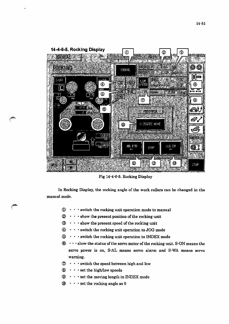
14-51
Fig 14-4-6-5. Rocking Display
In Rocking Display, the rocking angle of the work rollers can be changed in the
manual mode.
CD • • • switch the rocking unit operation mode to manual
® . . • show the present position of the rocking unit
@ ••• show the present speed ofthe rocking unit
@ • switch the rocking unit operation to JOG mode
@ • switch the rocking unit operation to INDEX mode
® ... show the status ofthe servo motor of the rocking unit. SoON means the
servo power is on, S-AL means servo alarm and S-WA means servo
warning.
(J) • • • switch the speed between high and low
® • . . set the highJlow speeds
® . . . set the moving length in INDEX mode
@) • set the rocking angle as 0
14-52
@ ••• start rocking unit operation either in JOG mode or INDEX mode. This
s\vitch is for turning the rocking unit counter clockwise.
@ - • • stop the. manual operation of the rocking unit
@ ••• start rocldng unit operation either in JOG mode or INDEX mode. This
switch is for turning the rocking unit clockwise.

14-53
14-4-6-6. AXIS Y Display(Option)
Fig 14-4-6-6_ AXIS Y Display
CD • • • switch the AXIS Y unit operation mode to manual
® . show the present position of the AXIS Y unit
@ • • • show the present speed of the AXIS Y unit
@ • switch the AXIS Y unit operation to JOG mode
@ • switch the AXIS Y unit operation to INDEX mode
® .•. show the status of the servo motor ofthe AXIS Y unit_ SoON means the
servo power is on, S-AL means servo alarm and S-WA means servo
warning_
(1) ••• switch the speed between high and low
® • . • set the highllow speeds
® • . • set the moving length in INDEX mode
@ • • • switch to AXIS Y MANUAL BASE page (Fig 14-4-6-6)
@ • • • switch to EQUAL PITCH MODE page (Fig 14-4-6-7)
@ • • • switch to FREE PITCH MODE page (Fig 14-4-6-8)
@ ••• move the AXIS Y unit to the wait position. Setting of the wait position
is available in Setting -AXIS Y Display.
@ ••• move the AXIS Y unit to the Rotate position. Setting of the Rotate

position is available in Setting -AXIS Y DiSplay.
@ • • • move the AXIS Y unit to the origin position.
14-54
@ ••• start AXIS Y unit operation either in JOG mode or INDEX mode. This
switch is for moving the AXIS Y to the front side.
@ • • • stop the manual operation of the AXIS Y unit
@ ••• startAXIS Y unit operation either in JOG mode or INDEX mode. This
switch is for moving the AXIS Y to the back side.

14-4-6-7. AXIS Y EQUAL PITCH Display(Option)
Fig 14-4-6-7_ AXIS Y EQUAL PITCH Display
CD • • • Y1 feed position setting number
® ..• Y1 feed position monitor
® . . • Y1 maximum value monitor
@ • • • Move to CDY1 position
@ • • • Y2 feed position setting number
@ •• • Y2 feed position monitor
crJ ••• Y2 maximum value monitor
@ • • • Moves to @Y2 position
® . . . Stop Y axis movement
14-55
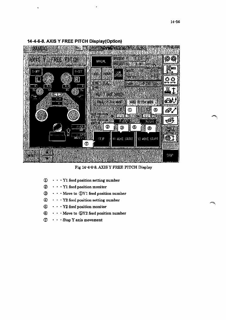
14-56
14-4-6-8. AXIS Y FREE PITCH Display(Option)
Fig 14-4-6-8. AXIS Y FREE PITCH Display
CD ••• Y1 feed position setting number
® ... Y1 feed position monitor
® ... Move to CDY1 feed position number
@ ••• Y2 feed position setting number
@ ••• Y2 feed position monitor
@ ••• Move to @Y2 feed position number
(1J ••• Stop Y axis movement
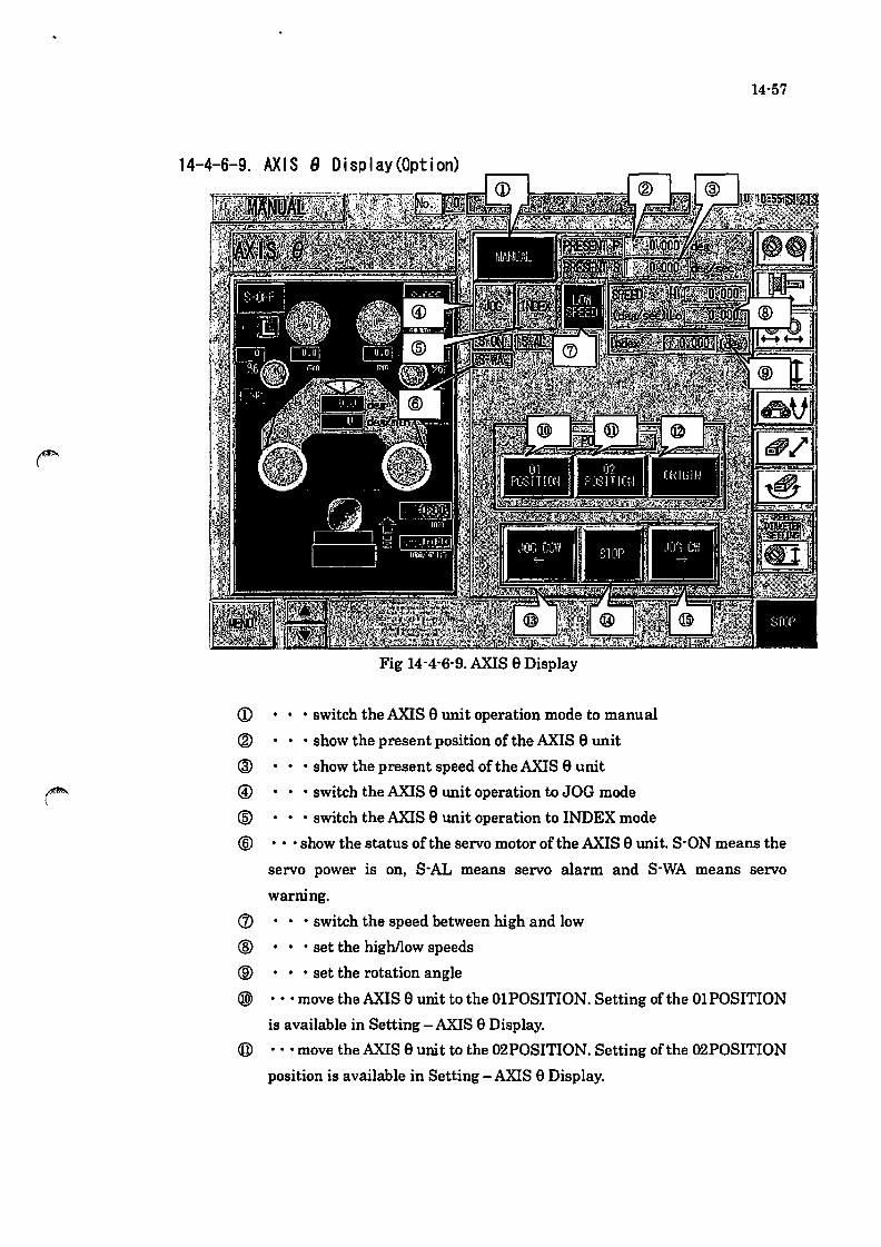
14-57
14-4-6-9. AX IS 8 0 i sp I ay (Opt ion)
Fig 14-4-6-9. AXIS e Display
CD ••• switch the AXIS e lUlit operation mode to manual
® ... show the present position of the AXIS e lUlit
@ • show the present speed of the AXIS e unit
@ ••• switch the AXIS e lUlit operation to JOG mode
® . switch the AXIS e Wlit operation to INDEX mode
® ... show the status of the servo motor of the AXIS e unit. SoON means the
servo power is on, S-AL means servo alarm and S-WA means servo
warning.
(i) ••• switch the speed between high and low
® ..• set the highllow speeds
® ... set the rotation angle
@ ••• move the AXIS e unit to the OlPOSITION. Setting of the OlPOSITION
is available in Setting - AXIS e Display.
® ... move the AXIS e unit to the 02POSITION. Setting of the 02POSITION
position is available in Setting -AXIS e Display.

14-58
@ ••• AXIS e unit returns to origin
@ ••• startAXISe unit operation either in JOG mode or INDEX mode. If
pressing this switch, AXIS e rotates CCW.
@ ••• stop the manual operation of the AXIS e unit
@ ••• start.AXlS e unit operation either in JOG mode or INDEX mode. If
pressing this switch, AXIS e rotates cw.

14-59
14-4-7. Process Data Select Display
Fig 14-4'7 Process Data Select Display
In Process Data Select Display, recipe change, title change, read'out and copy are
available.
CD Folder No.· • • show the folder number of the read' out recipe
® Recipe No .••• show the recipe number read out from the data group of the registered
process conditions
® Recipe Title· • • show the recipe title of the selected recipe number
® Current Name Change· • • change the recipe title. If touching this button to change
the selected recipe title, title change page opens.
® Recipe list· • • show the registered recipe titles
@ Read'out selection switch· • • specifies a recipe number to read out
(j) Read'out switch· •• read the data of the recipe number that is selected by the
read'out switch. If touching the button, the confU'mation/execution page appears.
® Copy switch· • • save currently selected recipe with new recipe number. If touching
this button, confirmation/execution button appears.

· Save Data Schematic
<Running Data Area> <SavingArea 1>
I Recipe~
Editable
Process condition data
1
~2 3
I Register>
14-60
< Saving Area 2 >
I FOlderN~ 1
tf? ~:
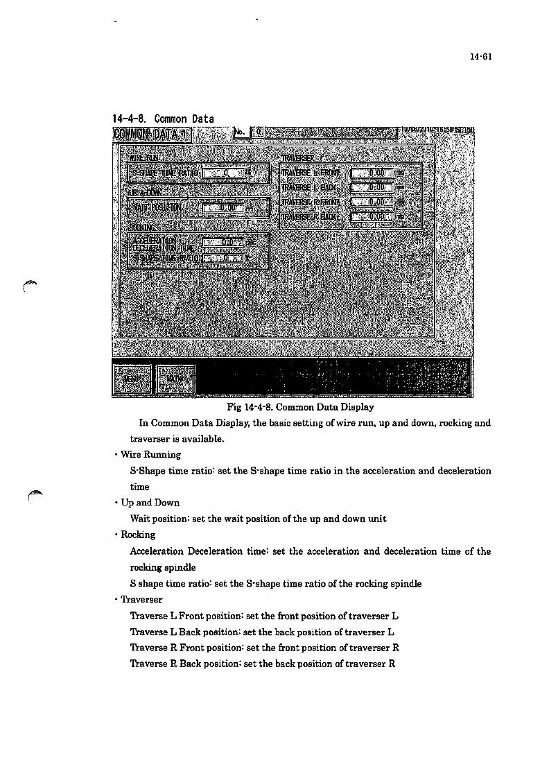
14·61
14-4-8. Common Data
Fig 14-4-8. Common Data Display
In Common Data Display, the basic setting of wire run, up and down, rocking and
traverser is available.
• Wrre Running
S'Shape time ratio: set the S-shape time ratio in the acceleration and deceleration
time
• Up and Down
Wait position: set the wait position ofthe up and down unit
• Rocking
Acceleration Deceleration time: set the acceleration and deceleration time of the
rocking spindle
S shape time ratio: set the S-shape time ratio of the rocking spindle
• Traverser
Traverse L Front position: set the front position of traverser L
Traverse L Back position: set the back position of traverser L
Traverse R Front position: set the front position of traverser R
Traverse R Back position: set the back position of traverser R

14-4-9. Maintenance Data Display
Fig 14-4-9_ Maintenance Data Display
• Wire Remain
set the wire length loaded on the reel
the value increases and decreases according to the machine operation
Always input wire length when replacing wire.
• Wire Remain Warning
Set the wire remaining length for alarm
14-62
Alarm occurs when the wire remaining length is more than the MAX length
and less than the MIN length
• Work Roller Operating Time and Pulley Operating Time and Assist Pulley Operating
Time
Total time' •• records the time during wire running, if pressing "RESET' button,
the value is reset.
Alarm time' •• Alarm occurs when the total operating time reaches the alarm
time.
• Cutting Coolant Operating Time
Total time' •• records the time while slurry is discharging, if pressing "RESET'

14-63
button, the value is reset.
Alarm time· •• Alarm occurs when the cumulation time reaches the alarm time.
• Number of slicing (times)
Number of slicing· • • show the number of slicing time, if pressing "RESET'
button, the value is reset.
Warning· • • alarm occurs when the number of slicing reaches the number in
this box.
• Wire tension
set target tension
• Regulator pressure
show the value calculated from the target wire tension (N)
*Regulator should be adjusted according to this value_
• SEITING The display switches to Pressure Setting.(Isecond)
Please set Xl,X2,Yl and Y2. after touching an input permission switch.
Wire tension measurements : Xl. X2 (Xl <X2) Pressure Regulator adjustment : Yl. Y2 (Yl <Y2)
Fig 14-4-9-2.Pressure Setting Display
• Main axis operating time
record while wire is running

14-64
14-4-10. Engineer Data Display
Fig 14-4-10-1. Engineer Data
• Door switch
switch enable/disable of the door switch, if setting enable, alarm occurs
when the door opens.
• BZ time
change the time of buzzing sound (15 sec or constant)
• Count sensor
"WITH" is set in normal operation
• Display automatic
set 'WITH" to automatically move to the alarm page when alarm occurs
• Language switch
set 'WITH" to display the language switch in each page
• Traverse middle point movement
Press 'WITH" when using the traverse middle point movement
• TABLE AXIS Y(Option)
'lb use axis Y, set ''USE''.
• TABLE AXIS e(Option)
'1b use axis e, set ''USE''.
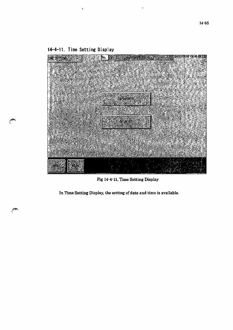
14-65
14-4-11. Time Setting Display
Fig 14-4-11. Time Setting Display
In Time Setting Display, the setting of date and time is available_

14-66
14-4-12. Tool Display
Fig 14-4-12-1. Thol Display
• Servo monitor
Jump to the servo motor (stepping motor) information display/operation page
(FigI4-4-12-2)
• Servo gain
Jump to the servo motor gain adjustment page (Fig 14-4-12-5)
• Servo parameters
Jump to the servo parameters page (Fig 14-4-12-9)
• Tensioner gain
Jump to the tensioner gain adjustment page (Fig 14-4-12-13)
• Initial transfer
Jump to the initial value transfer page (Fig 14-4-12-14)
·110 Check
Jump to the I/O check page (Fig 14-4-12-17)
The forced output is available by pressing the forced output switch
(Fig 14-4-12-18)

14·67
Fig 14-4-12-2. Servo Monitor Display
In Servo Monitor Display, turning ON/OFF of servo motors, setting origin position,
checking alarms and warnings, checking present pulse amount and present speed
are available.
<D S-ON' • • Change ON and OFF each time when pressing the switch.
SoON: Servo ON (Operation preparation is completed)
S-OFF: Servo OFF (Operation preparation is not completed)
The normal operation is available when SoON indicates with
flashing green lamp.
If the alarm occurs, the lamp may extinguish during SoON is
indicating.
® Origin set· •• The pop-up window shown in Fig 14-4-12-3 appears when
pressing this switch. The origin set is available on the screen.

14-68
Fig 14-4-12-3. Servo Origin Set
OK· • • Decide current position of the up and down unit as original position_
Press OK switch, and then the complete screen shown in Fig
14-3-2-21-4 appears when the setting is completed.
Press OK, and the operation is finished when the screen
disappears.
Cancel' • • Close this pop-up window.
Fig. 14-4-12-4 Operation Completion
* The other units can be set the origin point to perform same procedures.

14-69
@RESET' • • The pop-up window shown in Fig 14-4-12-54 appears when pressing this
switch. The ABS-ENCO reset can be performed on this screen.
(ABS-ANCO is abbreviation of the Absolute Encoder,)
Fig. 14-4-12-5.ABS-ENCO reset
OK· • • Start the ABS-ENCO reset operation by pressing "OK" screen button
longer.
Fig 14-4-12-6 appears during processing.
Fig 14-4-12-7 appears when the operation is completed. Press "OK"
and the operation is completed when the screen disappears.
Cancel • • • Close this pop-up screen.
Fig. 14-4-12-6. Processing

14-70
Fig. 14-4-12-7. Operation completion
* The other units can be reset the ABS-ENCO to perform same procedures.

14-71
Fig_ 14-4-12-8 Servo Gain Display
In Servo Gain Display, confirmation and adjustment of servo gain in each reel axis is
available_
CD • • • If pressing this button, the gain value is set as standard value. In case this
button is turned on, gain cannot be changed.
® .. . If pressing this button, arbitral gain value can be set.

14-72
Fig 14-4-12-9 Servo Parameters Display
It is available to set and change the parameter of servo motor on the Servo
Parameters_
CD • • • Press the !Notch Filted Notch Filter Screen appears_
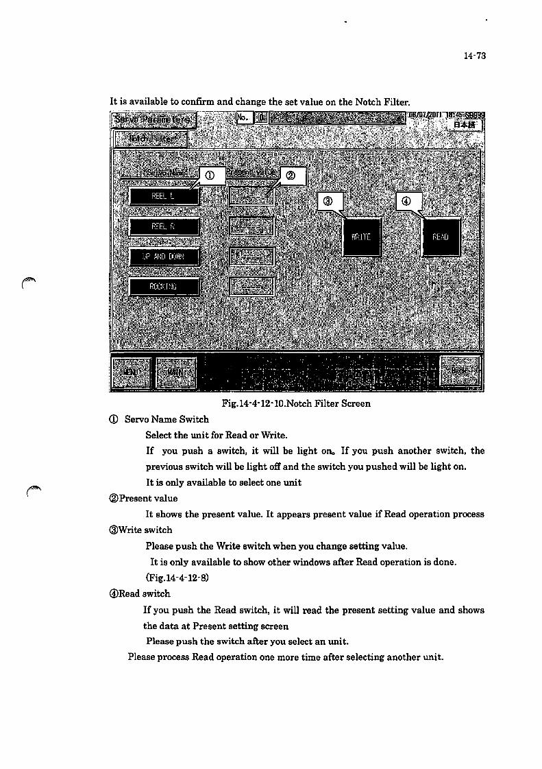
14-73
It is available to confirm and change the set value on the Notch Filter.
Fig. 14-4-12-1O.Notch Filter Screen
CD Servo Name Switch
Select the unit for Read or Write.
If you push a switch, it will be light on.. If you push another switch, the
previous switch will be light oft' and the switch you pushed will be light on.
It is only available to select one unit
(IDPresent value
It shows the present value. It appears present value if Read operation process
@Write switch
Please push the Write switch when you change setting value.
It is only available to show other windows after Read operation is done.
(Fig. 14-4-12-S)
@Read switch
If you push the Read switch, it will read the present setting value and shows
the data at Present setting screen
Please push the switch after you select an unit.
Please process Read operation one more time after selecting another unit.

14-74
• Changing Setting value
The window as below appears when you push the !Write executioDl switch.*mlj. It
is only available after Read and Write operation.
Fig. 14-4-12-11.Notch Filter Screen
CD Setting
Putting data is available when you push the yellow part (Putting number
window appears)
Please put the value you want to change.
®Write execution
Push the switch long when you change setting value. Setting value will be
written in Servo.
@ ESC
Close the screen. Please push the switch to change setting value.
If Read and Write process, it shows the screen as below and notice operation is done.
Operation is done after pushing OK switch.
Fig. 14-4-12-12.Notch Filter Screen

14-75
Fig. 14-4-12-13. '1'ensioner Gain Display
In '1'ensioner Gain Display, confirmation and adjustment of tensioner gain is available.
CD • • • If pressing this button, the gain value is set as standard value. In case this
button is turned on, gain cannot be changed.
® . . . If pressing this button, arbitral gain value can be set.

Fig. 14-4-12-14. Initial Transfer Display
In Initial Transfer Display, initial data transfer of the parameters is available .
• Process Data Initial Transfer ... The process data initialtransferwindow
(Fig. 14-4-12-15) pops up .
• Default Setting Initial Transfer ... The default setting initial transfer window
(Fig. 14-4-2-16) pops up.
14-76
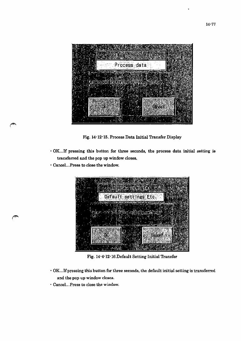
14-77
Fig_ 14-12-15. Process Data Initial Transfer Display
• OK. .. If pressing this button for three seconds, the process data initial setting is
transferred and the pop up window closes.
• Cancel. .. Press to close the window.
Fig. 14-4-12-16.Default Setting Initial Transfer
• OK. .. If pressing this button for three seconds, the default initial setting is transferred
and the pop up window closes.
• CanceL.Press to close the window.

Fig_ 14-4-12-17_110 check screen
Each input and output condition can be confirmed on the 110 check screen.
The indicator turns to Green when ON condition.
Forced output· • • When pressing this switch, the forced output is available.
14-78

14-79
Fig. 14-4-12-18.110 check forced output screen
Embossed switch· • • Output the address while pressing the switch.

14-80
14-4-13. File Manager
Fig 14-4-13. File Manager Display
In File Manager Display, upgrading motion system, saving process data and
restoring MP are available.
• Monitor System Upgrade
move to the page for changing the displayed data on the touch panel. (for version up
etc.)
Refer to exhibit
• Restore
move to the page for changing machine movement program (version up etc)
Refer to exhibit
• WSDBU
move to the page for savinglloading the set data
Refer to exhibit
• Exit System
exit the touch panel display. (display Windows desk top display)
Refer to exhibit
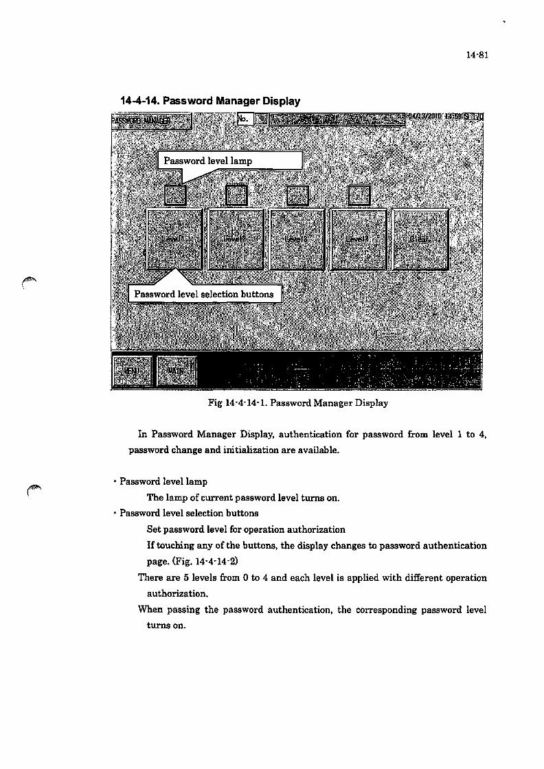
14-81
14-4-14. Password Manager Display
Fig 14-4-14-1. Password Manager Display
In Password Manager Display, authentication for password from level 1 to 4,
password change and initialization are available .
• Password level lamp
The lamp of current password level turns on .
• Password level selection buttons
Set password level for operation authorization
If touching any of the buttons, the display changes to password authentication
page. (Fig. 14-4-14-2)
There are 5 levels from 0 to 4 and each level is applied with different operation
authorization.
When passing the password authentication, the corresponding password level
turns on.
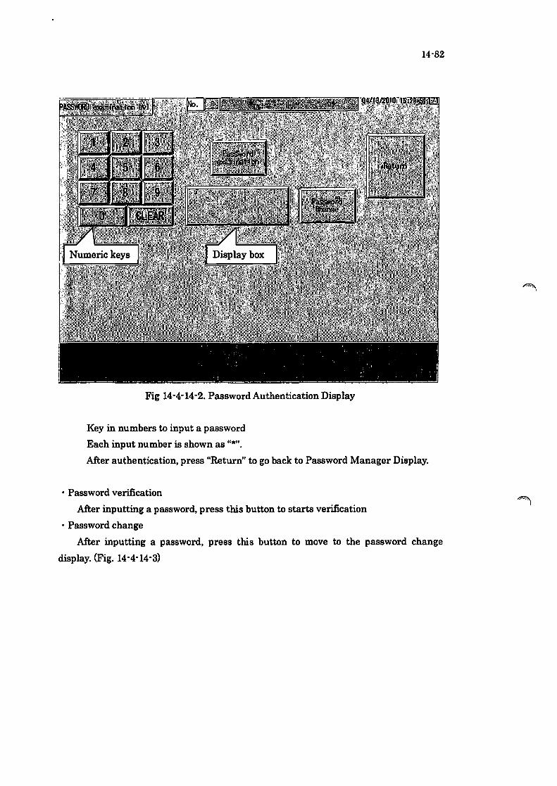
Fig 14-4-14-2. Password Authentication Display
Key in numbers to input a password
Each input number is shown as "*".
14-82
After authentication, press "Return" to go back to Password Manager Display .
• Password verification
After inputting a password, press this button to starts verification
• Password change
After inputting a password, press this button to move to the password change
display. (Fig. 14-4-14-3)
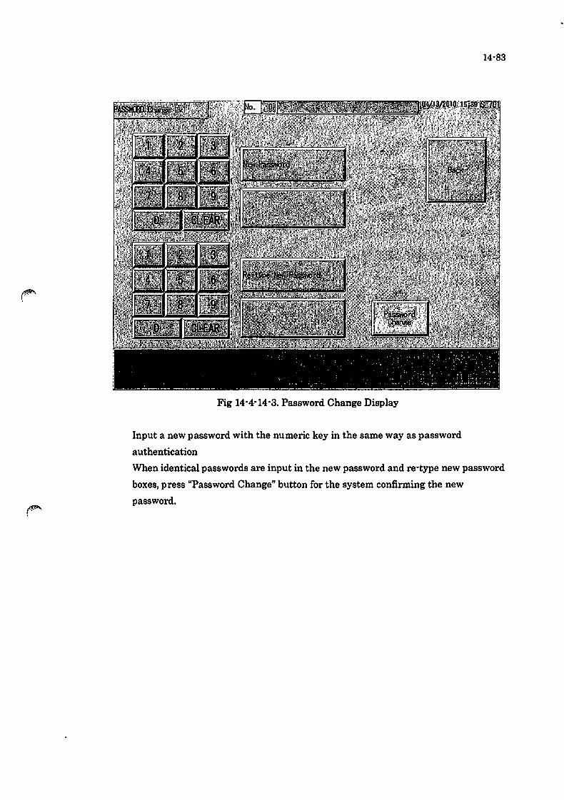
Fig 14-4-14-3. Password Change Display
Input a new password with the numeric key in the same way as password
authentication
14-83
When identical passwords are input in the new password and re-type new password
boxes, press "Password Change" button for the system confirming the new
password.
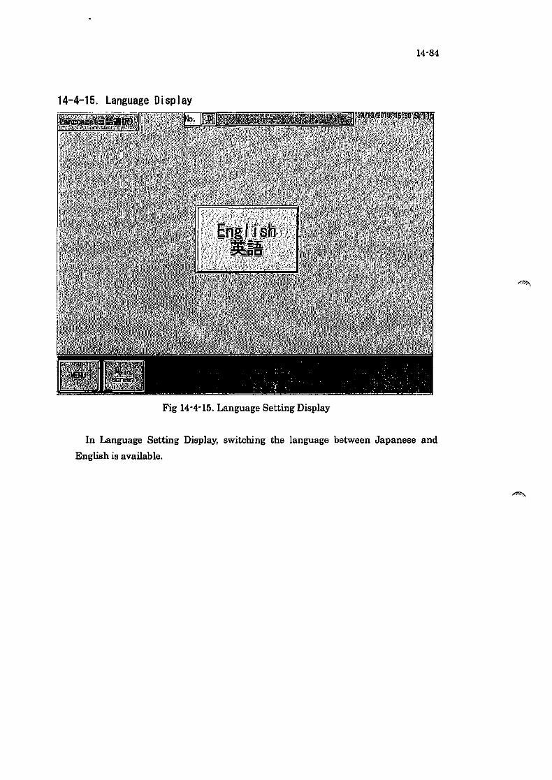
14-84
14-4-15. Language Display
Fig 14-4-15. Language Setting Display
In Language Setting Display, switching the language between Japanese and
English is available.
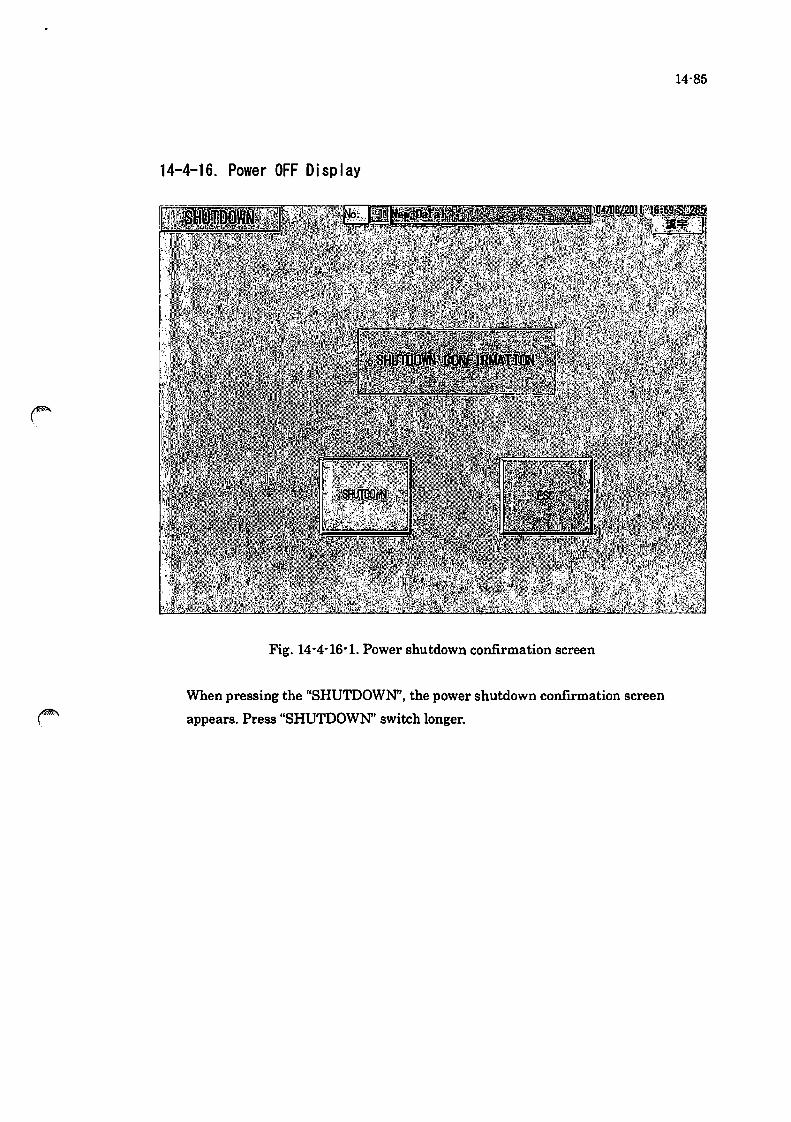
14-4-16. Power OFF Display
Fig. 14-4-16-1. Power shutdown confirmation screen
When pressing the "SHUTDOWN', the power shutdown confirmation screen
appears. Press "SHUTDOWN' switch longer.
14-85

14-86
Fig. 14-4-16-2. Shutdown processing
Saving the setting data.

14-87
Fig_ 14-4-16-3. Shutdown processing
The settings are correctly saved. Press "SHUTDOWN' and turn the machine power
source OFF.

14-88
14-4-17_ Setting List
Fig. 14-4-17-1. Setting List
Enable to confirm the current settings, but not available to change settings.
CD ••• Press this switch to confirm the stage setting.
® ••. Press this switch to confirm the y. e settings (Option>.

14-89
Stage Setting Display
Confirm the parameter of Stage Setting. o
Fig. 14-4-17-2. Stage setting list

Option Setting Display
Enable to confll'1ll the processing data for each stage, but not available to
change the settings.
Fig. 14-4-17-3.Y· 8 list
14-90

14-5.Error 14-5-1. ErrorMessage
Emergency stop
Door open
Low air
Drive power OFF
Pump inverter output
current error
Servo alarm reel L
The emergency stop
switch is being
pressed.
The front door was
opened
The pressure is below
14-91
1. Confirm the safety and tum the emergency
stop switch to cancel the locking state.
2. Touch the reset switch to release.
3. Press the drive power switch for
energization.
Check the door is open.
the setting value of the Check and recover the air pressure.
pressure switch.
Drive power is off.
Current value for the
pump is not rated
value.
Real L control error
1. Press the drive power switch for
energization.
2. Check the fuse (F**> in the control box and
replace if it is defective.
Confirm the connector connection for the
pump.
(This error is detected when the discharge and
stir setting value is over 5hz)
1. See the manual for the servo pack alarm
code and follow the instruction. (*1)
2. Check the load of the axis in case the error is
a deviation error.
3. In case the error is not caused by cause
above. hardware such as parameter. drivers.
motors may be defective.

Servo alarm reel R Real R control error
Servo alarm up and down Lifting axis control
axis error
Servo alarm rocking axis Rocking axis control
error
Servo alarm traverser Traverser L control
L error
14-92
1. See the manual for the servo pack alarm
code and follow the instruction. (*1)
2. Check the load of the axis in case the error is
a deviation error.
3. In case the error is not caused by cause
above. hardware such as parameter. drivers.
motors may be defective.
1. See the manual for the servo pack alarm
code and follow the instruction. (*1)
2. Check the load of the axis in case the error is
a deviation error.
3. In case the error is not caused by cause
above. hardware such as parameter. drivers.
motors may be defective.
1. See the manual for the servo pack alarm
code and follow the instruction. (*1)
2. Check the load of the axis in case the error is
a deviation error.
3. In case the error is not caused by cause
above. hardware such as parameter. drivers.
motors may be defective.
1. When the system detects an error in the
driver. the red LED light of the driver blinks and
alarm code appears.
2. Check the alarm code in the manual and
follow the instruction. (*2)
3. In case the error is not caused by the cause
above. hardware such as parameters. drivers
and motors may be defective.
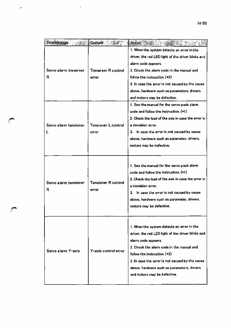
14-93
i':~~~~:' J ,L~~i~~[;) ~;q.~ij~~~~:" __ ~"J~~?}f;':: ::: k~s~~:~~~.:J~·'}'_~{~f:"~~~,~}i.J~i~K;~!1 1. When the system detects an error in the
driver. the red LED light of the driver blinks and
alarm code appears.
Servo alarm traverser Traverser R control 2. Check the alarm code in the manual and
R error follow the instruction. (*2)
Servo alarm tensioner Tensioner L control
L error
Servo alarm tensioner Tensioner R control
R error
Servo alarm V-axis V-axis control error
3. In case the error is not caused by the cause
above. hardware such as parameters. drivers
and motors may be defective.
1. See the manual for the servo pack alarm
code and follow the instruction. (*1)
2. Check the load of the axis in case the error is
a deviation error.
3. In case the error is not caused by cause
above. hardware such as parameter. drivers.
motors may be defective.
1. See the manual for the servo pack alarm
code and follow the instruction (*0
2. Check the load of the axis in case the error is
a deviation error.
3. In case the error is not caused by cause
above. hardware such as parameter. drivers.
motors may be defective.
1. When the system detects an error in the
driver. the red LED light of the driver blinks and
alarm code appears.
2. Check the alarm code in the manual and
follow the instruction. {*2}
3. In case the error is not caused by the cause
above. hardware such as parameters. drivers
and motors may be defective.

SelVo alarm B -axis
Pump inverter error
MP2500 error
Up and down limit error
Rocking axis limit error
Traverse L limit error
B -axis control error
Inverter was wrong
with the working
coolant pump.
Controller error
occurred.
Up-down axis is
outside the specified
area
14-94
1. When the system detects an error in the
driver, the red LED light of the driver blinks and
alarm code appears.
2. Check the alarm code in the manual and
follow the instruction. (*2)
3. In case the error is not caused by the cause
above, hardware such as parameters, drivers
and motors may be defective.
When the error is detected,
1. the error message appears and ALM lamp is
turned on for alerting the LED operator (LCD
operator).
2. Check the alarm code in the manual and
follow the instruction. (*3)
Controller is defective. Please contact Takatori
and report the error occurrecne condition.
Check the present position and whether the
up-down position setting data is correct.
Rocking axis is outside Check the present position and whether the
the specified area. up-down position setting data is correct.
Traverse L -axis is
outside the specified
area.
Check the present position and whether
Travers L position setting data is correct.

14-95
~~tta~~~~s'~;.;;;,{~\~~i:.-:\ (:c~6Hi~~:;~~K'h_ti:~:3~¥:~~: fA~~~fi\:;~bin~;;~"~~){--,;:<,:,.i; :·,:;-·:-L~1it~}-·_~i::;:~1(1&.
Traverse R-axis is
Traverse R limit error outside the specified Check the present position and whether
Travers R position setting data is correct. ares.
Y-axis position is
Y-axis limit error outside the specified Check the present position and whether Y-axis
position setting data is correct. area.
t. Check ifthe wire is not disconnected and
Wire tension control Tension controlling
connect the wire if disconnected. area exceeds the
error 2. Measure the diameter of the reel and set the specified value.
diameter correctly.
Rotation sensor does Take off the cover and check if the sensor's Count sensor error
not receive a signal. cord is normal.
t. Check ifthe pressure of the tensioner Lis
not too low. If it is too low, adjust the pressure
with the regulator. Tensioner L was to
Tensioner L forward move, but it is was in 2. Check if the solenoid of tensioner Lis acting
error the open end in 5 correctly.
seconds.
3. Check if the cylinder, air hose and driving part
of the tensioner L are working correctly.
t. Check if the pressure of the tensioner Li s
not too low. If it is too low, acljust the pressure
T ensioner L was to with the regulator.
open, but it could not 2. Check if the solenoid of tensioner Lis acting Tensioner L return error
move to the open end correctly.3. Check if the cylinder, air hose and
in five seconds. driving part ofthe tensioner L are working
correctly.

14-96
.~'.§T~~~:~i¥i·:::·:~;:;?\~~:Y.t~~ Lq~~~l\t~ -'~r,--.~ .~, ~':
-
t!~$', ::~n\-;K-\tT"ij,+lli,;L\:dL,J·:",;'1':t71)~;~, __ \Z[;:{;i~8 ·5 1. Check ifthe pressure of the tensioner R is
not too low. If it is too low, acljust the pressure
with the regulator. Tensioner R was to
Tensioner R forward 2. Check if the solenoid of tensioner R is acting move, but it was in the
error correctly. open end in 5 seconds.
3. Check if the cylinder, air hose and driving part
of the tensioner R are working correct/yo
1. Check ifthe pressure of the tensioner R is
not too low. If it is too low, adjust the pressure
with the regulator. Tensioner R was to
open, but it could not 2. Check if the solenoid of tensioner R is acting T ensioner R return error
move to the open end correctly.
in five seconds.
3. Check if the cyr.nder. air hose and driving part
of the tensioner R are working correctly.
Confirm the following value on the processing
The set value of the condition - up and down. and set the slice end
Slice end position setting slice end position is position is less than 183mm
limit over over limitation of the • Start Offset
up and down stroke. • Contact position
• Cutting amount
Yl Position setting UMIT The set value of the Yl Check ifthe set data is normal.
over is over limitation
Y2 Position setting UMIT The set value of the Y2 Check ifthe set data is normal.
over is over limitation
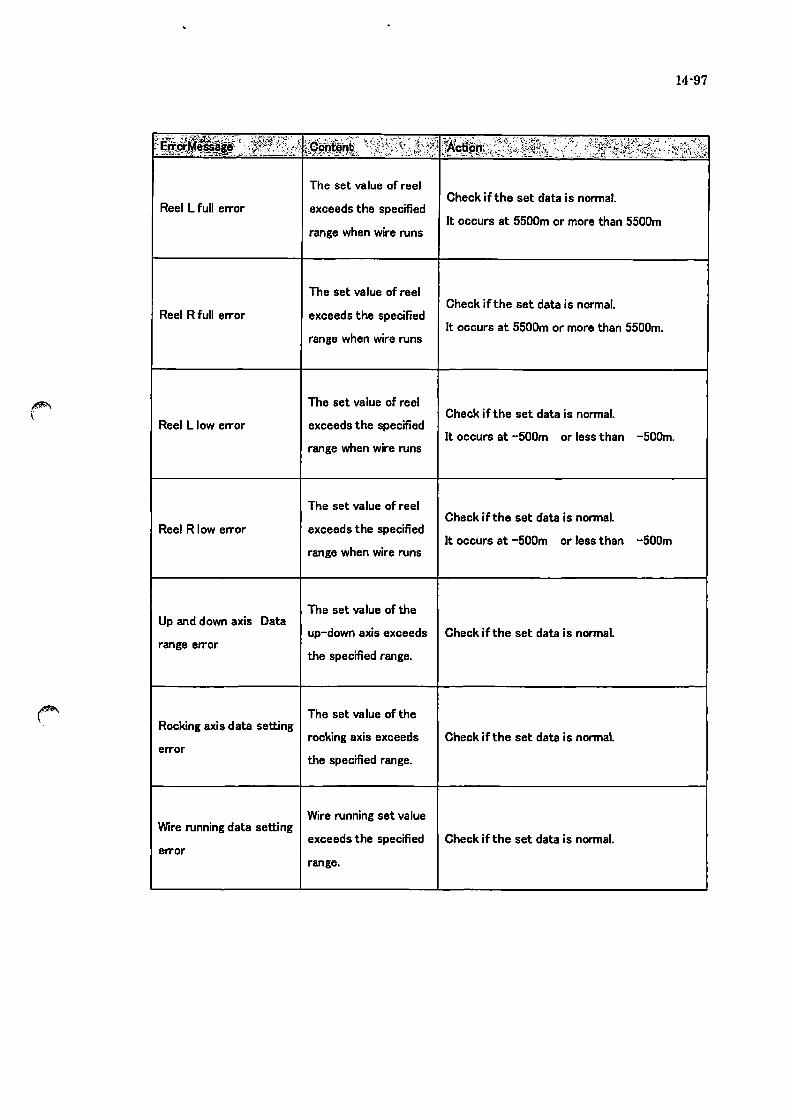
Reel L full error
Reel R full error
Reel L low error
Reel R low error
Up and down axis Data
range error
Rocking axis data setting
error
Wire running data setting
error
The set value of reel
exceeds the specified
range when wire runs
The set value of reel
exceeds the specified
range when wire runs
The set value of reel
exceeds the specified
range when wire runs
The set value of reel
exceeds the specified
range when wire runs
The set value of the
Check ifthe set data is normal.
It occurs at 5500m or more than 5500m
Check ifthe set data is normal.
It occurs at 5500m or more than 5500m.
Check ifthe set data is normal.
It occurs at -500m or less than -500m.
Check if the set data is normal.
It occurs at -500m or less than -SOOm
up-down axis exceeds Check if the set data is normal.
the specified range.
The set value of the
rocking axis exceeds
the specified range.
Wire running set value
Check ifthe set data is normal.
exceeds the specified Check ifthe set data is normal.
range.
14-97
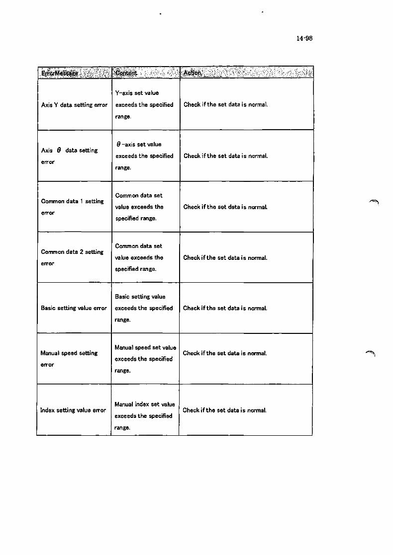
Y-axis set value
Axis Y data setting error exceeds the specified Check ifthe set data is normal.
Axis 9 data setting
error
Common data 1 setting
error
Common data 2 setting
error
range.
8 -axis set value
exceeds the specified Check ifthe set data is normal.
range.
Common data set
value exceeds the
specified range.
Common data set
value exceeds the
specified range.
Basic setting value
Check if the set data is normal.
Check ifthe set data is normal.
Basic setting value error exceeds the specified Check if the set data is normal.
Manual speed setting
error
Index setting value error
range.
Manual speed set value
exceeds the specified
range.
Manual index set value
exceeds the specified
range.
Check ifthe set data is normal.
Check ifthe set data is normal.
14-98
.~ .,

14-99
Maintenance set value Maintenance setting
exceeds the specified Check ifthe set data is normal. value error
range.
Maintenance set value Maintenance setting 2
value error exceeds the specified Check ifthe set data is normal.
range.
Stage data set value
Stage data setting error exceeds the specified
Stage setting Height
value line order error
range.
Stage setting Height
value is lower than
previous data
Check ifthe set data is normal.
Confinn the following value on the processing
condition - set value of next stage is higher
than previous data.
(It occurs at only stage mode and consecutive
mode.)

14-100
ErrorMessage Content Action
1. See the manual for the servo pack alarm
code and follow the instruction. (*1)
2. Check the load of the axis in case the error is
Reel L servo control a deviation error. Servo warning reel L
error 3. In case the error is not caused by cause
above. hardware such as parameter. drivers.
motors may be defective
1. See the manual for the servo pack alarm
code and follow the instruction. (*1>
2. Check the load of the axis in case the error is Reel R servo control
Servo warning reel R a deviation error. error
3. In case the error is not caused by cause
above. hardware such as parameter. drivers.
motors may be defective
1. See the manual for the servo pack alarm
code and follow the instruction. (*1)
Servo warning up and Up-down axis servo 2. Check the load of the axis in case the error is
down axis control error a deviation error.
3. In case the error is not caused by cause
above. hardware such as parameter. drivers.
motors may be defective
1. See the manual for the servo pack alarm
code and follow the instruction. (*1>
2. Check the load of the axis in case the error is Servo warning rocking Rocking axis servo
a deviation error. axis control error
3. In case the error is not caused by cause
above. hardware such as parameter. drivers.
motors may be defective

14-101
ErrorMessage . Content Action
1. When the system detects an error in the
driver. the red LED light of the driver blinks and
alarm code appears.
Servo warning traverser Traverser L servo 2. Check the alarm code in the manual and
L control error follow the instruction. (*2)
3. In case the error is not caused by the cause
above. hardware such as parameters. drivers
and motors may be defective.
1. When the system detects an error in the
driver. the red LED light of the driver blinks and
alarm code appears.
2. Check the alarm code in the manual and Servo warning traverser Traverser R servo
follow the instruction. (*2) R control error
3. In case the error is not caused by the cause
above. hardware such as parameters. drivers
and motors may be defective.
1. See the manual for the servo pack alarm
code and follow the instruction. (*1)
2. Check the load of the axis in case the error is
Servo warning tensioner T ensioner L servo a deviation error.
L control error 3. In case the error is not caused by cause
above. hardware such as parameter. drivers.
motors may be defective
1. See the manual for the servo pack alarm
code and follow the instruction. (*1)
2. Check the load of the axis in case the error is Servo warning tensioner Tensioner R servo
a deviation error. R control error
3. In case the error is not caused by cause
above. hardware such as parameter. drivers.
motors may be defective

14-102
ErrorMessage Content Action
1. When the system detects an error in the
driver. the red LED light of the driver blinks and
alarm code appears.
Y-axis servo control 2. Check the alann code in the manual and Servo warning Y-axis
follow the instruction. (*2) error
3. In case the error is not caused by the cause
above. hardware such as parameters. drivers
and motors may be defective.
1. When the system detects an error in the
driver. the red LED light of the driver blinks and
alarm code appears.
8 -axis servo control 2. Check the alann code in the manual and Servo warning 8 -axis
follow the instruction. (*2) error
3. In case the error is not caused by the cause
above. hardware such as parameters. drivers
and motors may be defective.
1. Check ifthe driving power is input
Coolant pump inverter 2. When detecting minor failure or warning. error
Pump inverter warning message will appear to notice operators. error
See and follow the manual to work out the
problem. (*3)
Backup battery for 1. Battery needs to be replaced. Tum off the
moti on board of the
controller (MP2500) is power supply as long as possible until replacing
MP2500 battery low the battery. because the set data may be lost.
lower than the 2. Please contact T akatori for battery
specified value. replacement.
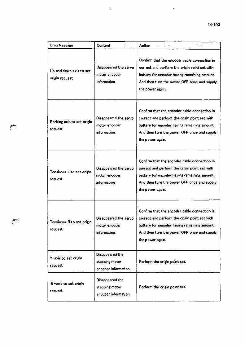
14'103
ErrorMessage Content Action
Confirm that the encoder cable connection is
Up and down axis to set Disappeared the servo correct and perform the origin point set with
motor encoder battery for encoder having remaining amount. origin request
information And then tum the power OFF once and supply
the power again,
Confirm that the encoder cable connection is
Disappeared the servo correct and perform the origin point set with Rocking axis to set origin
motor encoder battery for encoder having remaining amount. request
information And then tum the power OFF once and supply
the power again.
Confirm that the encoder cable connection is
Disappeared the servo correct and perform the origin point set with Tensioner L to set origin
motor encoder battery for encoder having remaining amount. request
information And then tum the power OFF once and supply
the power again.
Confirm that the encoder cable connection is
Disappeared the servo correct and perform the origin point set with T ensioner R to set origin
motor encoder battery for encoder having remaining amount. request
information And then tum the power OFF once and supply
the power again.
Disappeared the Y-axis to set origin
stepping motor Perform the origin point set. request
encoder information.
8 -axis to set origin Disappeared the
stepping motor Perform the origin point set. request
encoder information.

14-104
ErrorMessage Content Action
Disappeared the Traverser L to set origin
stepping motor Perform the origin point set request
encoder information.
Disappeared the Traverser R to set origin
stepping motor Perform the origin point set request
encoder information.
Reel L wire amount Replace the reel, check the set values in the
Reel L coiling warning exceeds the specified maintenance page and reset the counter as
value. necessary.
Reel R wire amount Replace the reel, check the set values in the
maintenance page and reset the counter as Reel R coiling warning exceeds the specified
necessary. value.
Reel L wire amount is Replace the reel, check the set values in the Reel L feeding low
lower than the maintenance page and reset the counter as warning
specified value. necessary.
Reel R wire amount is Reel R feeding low
lower than the Replace the reel, check the set values in the
warning specified value.
maintenance page and reset the counter as
necessary.
Tensioner L pulley life Tensioner L pulley life Replace the pully of the tensioner L. check the
counter reached the set values in the maintenance page and reset warning
set value. the counter as necessary.

14-105
ElTorMessage Content Action
Tensioner R pulley life T ensioner R pulley life Replace the pully of the tensioner R. check the
counter reached the set values in the maintenance page and reset waming
set value. the counter as necessary.
Work roller L life Replace the work roller L. check the set values
WR-L life waming counter reached the in the maintenance page and reset the counter
set value. as necessary.
Work roller R life Replace the work roller R. check the set values
WR-R life waming counter reached the in the maintenance page and reset the counter
set value. as necessary.
Replace the coolant. check the set values in the Coolant life counter
Coolant life waming reached the set value.
maintenance page and reset the counter as
necessary.
Number of auto slicing Check the set values in the maintenance page Total auto process
psocess reached the and reset the counter as necessary. warning
set value.
Assist pulley L life Confirm the set value on the maintenance page Assist pulley L life
count reached the set and perform the counter reset Replace the waming
assist pulley L if necessary. value.

14·106
ErrorMessage Content Action
Assist pulley R life Confirm the set value on the maintenance page Assist pulley R life
count reached the set and perform the counter reset. Replace the warning
value. assist pulley R if necessary.
Confirm the following value on the processing
The set value of the condition - up and down. and set the slice end
Slice End Position Data slice end position is position is less than 180mm.
Setting warning over limitation of the • Start Offset
up and down stroke. • Contact position
• Cutting amount
Please change a preset value so that the
multiplication value of
acceleration-and-deceleration time and
S ratio becomes below 0.51 (sec).
Acceleration-and Example 1
-deceleration time or acceleration-and-deceleration time
Rocking S-ratio setting S ratio setting is (sec): 0.5
value over too large. S-ratio (6):30
0.5 x 0.3 = 0.15 (sec)
Example 2
acceleration-and-deceleration time
(sec): 1.0
S-ratio (%):40
1.0 x 0.4 = 0.40 (sec)

• 14-4-2. Footnote Explanation
* 1: Yasukawa Electric ~ V Series Users Manual DesignlMaintenance Edition
Chapter 9: Troubleshooting
*2: Oriental Motor AS Series
MECHATROLINK- n Driver Users Manual
Troubleshooting
*3: Yasukawa Inverter V1000 Teclmical Manual
6.3 Inverter Alarm and Error Function
6.5 Minor FailurelWarning
14-107

14-108
14-6. Replacing battery 14-6-1. Replacing servo battery procedure
needs to proceed with extreme caution due to applYin~
Tensioner L Tensioner R
<Preparation>
Press the emergency stop
located on the front side of the
machine.
Supply the breaker while leaving the
control board door.
When reboot the machine, press the
reset switch on the alarm screen.
Confirm that the [Emergency Stop
SW 0 N] indication is not cleared.
Unplug the connector (CN2)
connecting to the servo battery cable
indicated alarm.
Release the lock mechanism by
pinching upper and lower portion
and withdraw the cable.
The servo back indication repeats A,
9, I, 0, • alternately.
<CN2 Enlarged View)
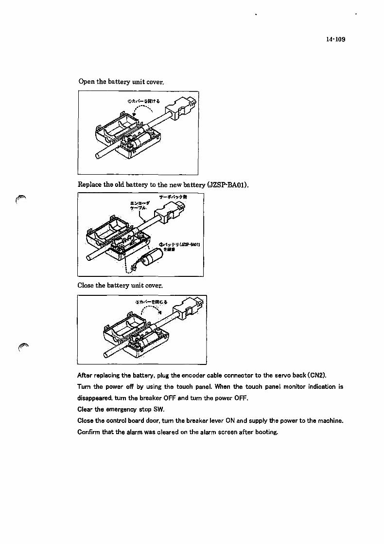
Open the battery unit cover.
Replace the old battery to the new battery (JZSP-BAOl).
"f-lIM'7 ~ II
Close the battery unit cover.
After replacing the battery, plug the encoder cable connector to the servo back (CN2).
14-109
Tum the power off by using the touch panel. When the touch panel monitor indication is
disappeared, tum the breaker OFF and tum the power OFF.
Clear the emergency stop SW.
Close the control board door, tum the breaker lever ON and supply the power to the machine.
Confirm that the alarm was cleared on the alarm screen after booting.

14·110
14-6-2. Replacing the stepping battery
!Be sure that this operation is proceed after turning the power OFF.I
Travarser L Battery (Upper)
Traverser R Battery (Lower)
Release the screws retaining
the metal band and replace the
old battery to the new battery.
BATTERY
Connect the leading wire from
the battery to the stepping driver
[CN2).
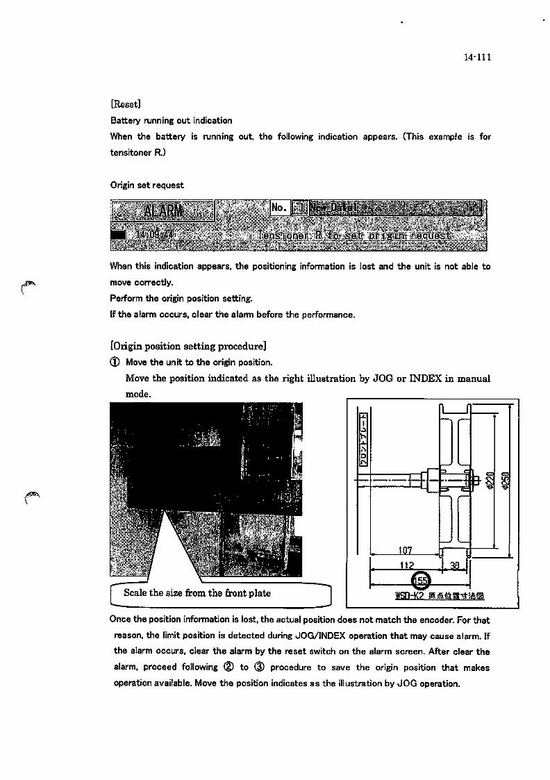
14-111
[Reset]
Battery running out indication
When the battery is running out, the following indication appears. (This example is for
tensitoner R)
Origin set request
When this indication appears, the positioning information is lost and the unit is not able to
move correctly.
Perform the origin position setting.
If the alarm occurs, clear the alann before the performance.
[Origin position setting procedure]
<D Move the un it to the origin position.
Move the position indicated as the right illustration by JOG or INDEX in manual
mode.
---l-1-t--.. --H ......
Once the position information is lost, the actual position does not match the encoder. For that
reason, the limit position is detected during JOG/INDEX operation that may cause alarm. If
the alarm occurs, clear the alarm by the reset switch on the alarm screen. After clear the
alarm. proceed following ® to @ procedure to save the origin position that makes
operation available. Move the position indicates as the illustration by JOG operation.
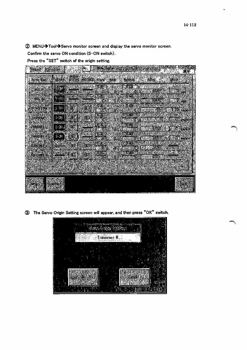
® MENU~Tool~Servo monitor screen and display the servo monitor screen.
Confirm the servo ON condition (S-ON switch).
Press the "SET" switch of the origin setting.
@ The Servo Origin Setting screen will appear, and then press "OK" switch.
14-112

14-113
@ Press "OK" when the complete screen appears.
@ Confirm the pulse value "0" and complete the operation. (± few pulse may occurs.)
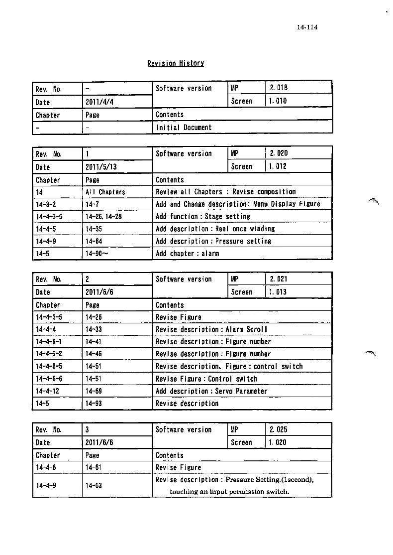
14·114
Revision HistorY
Rev. No. - Software version MP 2.018
Date 201114/4 Screen 1.010
Chapter Page Contents
- - Initial Document
Rev. No. 1 Software version MP 2. 020
Date 201115/13 Screen 1. 012
Chapter Page Contents 14 All Chapters Review all Chapters: Revise composition 14-3-2 14-7 Add and Change description: Menu Display Figure 14-4-3-5 14-26. 14-28 Add function: Stage setting 14-4-5 14-35 Add description: Reel once winding 14-4-9 14-64 Add description: Pressure setting 14-5 14-90- Add chapter: alarm
Rev. No. 2 Software version UP 2.021
Date 2011/6/6 Screen 1. 013
Chapter Page Contents 14-4-3-5 14-26 Revise Figure 14-4-4 14-33 Revise description: Alarm Scroll 14-4-6-1 14-41 Revise description: Figure number 14-4-6-2 14-46 Revise description: Figure number 14-4-6-5 14-51 Revise description. Figure: control swi tch 14-4-6-6 14-51 Revi se Figure: Control swi tch 14-4-12 14-69 Add description: Servo Parameter 14-5 14-93 Revise description
Rev. No. 3 Software version MP 2.025
Date 201116/6 Screen 1. 020
Chapter Page Contents 14-4-8 14-61 Revise Figure
14-4-9 14-63 Rev i se descr i pt ion: Pressure Setting.(lsecond),
touching an input permission switch.

14-115
-14-4-9 14-63 Revise Figure: Control swi tch
.. -.. --. -..... -~-
14-4-10 14-64 Rev i se Figure : Traversemiddle point movementswitch
Default Setting switch _.-. . 14-4-17 14-88 Revise Figure: Reel size switch deletion
Rev. No. 4 Software version MP 2.027
Date 2012/2/2 Screen 1. 022. 2. 022
Chapter Page Contents
14-5 14-106 Add description: Alarm

15·1
1 5. Warranty
The warranty period of this product is either one year or 2000 hours of use after the delivery inspection.
After this warranty period, we shall provide inspection services according to the separate maintenance
contract. Please note, however, that repair services provided for any defects arising from the following .
reasons shall be charged even in the warranty period:
<l)Any defects arising from the improper use of product by customers, including those caused by
falling the machine, giving a impact to the machine, or other reasons.
® Any defects arising from the Act of God including a fire, earthquake, flood, as well as abnormal
voltage applied to the machine.
@Any defects caused by defects of unauthorized equipment connected to this product.
@ Any defects arising from failure to follow the operating procedure and instruction described in the
manuals supplied with the product.