instruction manual residential electric...
TRANSCRIPT

1PRINTED IN THE U.S.A 0207 PART NO. 185762-000
SUPERSEDES PART NO. 184639-002
KEEP THIS MANUAL IN THE POCKET ON HEATER FOR FUTURE REFERENCEWHEN EVER MAINTENANCE ADJUSTMENT OR SERVICE IS REQUIRED.
ALL TECHNICAL AND WARRANTY QUESTIONS: SHOULD BE DIRECTED TO THE LOCAL DEALER FROM WHOM THE WATER HEATER WASPURCHASED. IF YOU ARE UNSUCCESSFUL, PLEASE WRITE TO THE COMPANY LISTED ON THE RATING PLATE ON THE WATER HEATER.
GAMA certification applies to allresidential electric water heaters withcapacities of 20 to 120 gallons. Inputrating of 12 Kw or less.
LISTED
Instruction Manual RESIDENTIAL ELECTRIC
WATER HEATERSMODELS 6-120
FOR POTABLE WATERHEATING ONLY
NOT SUITABLE FORSPACE HEATING
2
SAFE INSTALLATION, USE AND SERVICEYour safety and the safety of others is extremely important in the installation, use, and servicing of this water heater.
Many safety-related messages and instructions have been provided in this manual and on your own water heater to warn youand others of a potential injury hazard. Read and obey all safety messages and instructions throughout this manual. It isvery important that the meaning of each safety message is understood by you and others who install, use, or service thiswater heater.
This is the safety alert symbol. It is used to alertyou to potential personal injury hazards. Obey allsafety messages that follow this symbol to avoidpossible injury or death.
All safety messages will generally tell you about the type of hazard, what can happen if you do not follow the safety message, andhow to avoid the risk of injury.
The California Safe Drinking Water and Toxic Enforcement Act requires the Governor of California to publish a list of substancesknown to the State of California to cause cancer, birth defects, or other reproductive harm, and requires businesses to warn ofpotential exposure to such substances.
This product contains a chemical known to the State of California to cause cancer, birth defects, or other reproductive harm. Thisappliance can cause low level exposure to some of the substances listed, including formaldehyde.
IMPORTANT DEFINITIONS
• Qualified Installer: A qualified installer must have ability equivalent to a licensed tradesman in the fields of plumbing and electricalinstallation of these appliances. This would include a thorough understanding of the requirements of the National Electrical Code andapplicable local electrical and plumbing codes (and tools necessary to confirm proper installation and operation of the water heater) asthey relate to the installation of electric water heaters. The qualified installer must have a thorough understanding of the water heaterInstruction Manual.
• Service Agency: A service agency also must have ability equivalent to a licensed tradesman in the fields of plumbing and electricalinstallation of these appliances. This would include a thorough understanding of the requirements of the National Electrical Code andapplicable local electrical and plumbing codes (and tools necessary to confirm proper installation and operation of the water heater) asthey relate to the installation of electric water heaters. The service agency must have a thorough understanding of the water heaterInstruction Manual.
DANGER
WARNING
CAUTION
DANGER indicates an imminentlyhazardous situation which, if not avoided,could result in death or injury.
WARNING indicates a potentially hazardoussituation which, if not avoided, could resultin death or injury.
CAUTION indicates a potentially hazardoussituation which, if not avoided, may resultin minor or moderate injury.
CAUTION used without the safety alertsymbol indicates a potentially hazardoussituation which, if not avoided, could resultin property damage.
CAUTION

3
GENERAL SAFETY

4
Thank You for purchasing this water heater. Properly installed andmaintained, it should give you years of trouble free service.
Abbreviations Found In This Instruction Manual:• ANSI - American National Standards Institute• ASME - American Society of Mechanical Engineers• GAMA - Gas Appliance Manufacturers Association• NEC - National Electrical Code• NFPA - National Fire Protection Association• UL - Underwriters Laboratories Inc.
PREPARING FOR THE INSTALLATION
1. Read the “General Safety” section of this manual first and thenthe entire manual carefully. If you don’t follow the safety rules,the water heater will not operate properly. It could cause DEATH,SERIOUS BODILY INJURY, AND/OR PROPERTY DAMAGE.
This manual contains instructions for the installation, operation,and maintenance of the electric water heater. It also containswarnings throughout the manual that you must read andunderstand. All warnings and all instructions are essential to theproper operation of the water heater and your safety. READ THEENTIRE MANUAL BEFORE ATTEMPTING TO INSTALL OROPERATE THE WATER HEATER.
2. The installation must conform with these instructions and thelocal code authority having jurisdiction and the requirements ofthe power company. In the absence of local code requirementsfollow NFPA-70, the National Electrical Code (current edition),which may be ordered from: National Fire Protection Association,1 Batterymarch Park, Quincy, MA 02269.
3. If after reading this manual you have any questions or do notunderstand any portion of the instructions, call the local utility orthe manufacturer whose name appears on the rating plate.
4. Carefully plan your intended placement of the waterheater. INSTALLATION OR SERVICE OF THIS WATERHEATER REQUIRES ABILITY EQUIVALENT TO THATOF A LICENSED TRADESMAN IN THE FIELD INVOLVED.PLUMBING AND ELECTRICAL WORK ARE REQUIRED.Examine the location to ensure the water heater complies withthe “Facts to Consider About the Location” section in this manual.
5. For California installation this water heater must be braced,anchored, or strapped to avoid falling or moving during anearthquake. See instructions for correct installation procedures.Instructions may be obtained from California Office of the StateArchitect, 400 P Street, Sacramento, CA 95814.
6. Massachusetts Code requires this water heater to be installed inaccordance with Massachusetts 248-CMR 2.00: State PlumbingCode and 248-CMR 5.00.
INTRODUCTION
SAFE INSTALLATION, USE AND SERVICE ............................................................................................................................................................ 2GENERAL SAFETY ..................................................................................................................................................................................................... 3INTRODUCTION .......................................................................................................................................................................................................... 4
Preparing for the New Installation ..................................................................................................................................................................... 4TABLE OF CONTENTS ............................................................................................................................................................................................... 4TYPICAL INSTALLATION ........................................................................................................................................................................................... 5MIXING VALVE USAGE .............................................................................................................................................................................................. 6LOCATING THE NEW WATER HEATER ............................................................................................................................................................... 6-7
Facts to Consider About Location ..................................................................................................................................................................... 6Insulation Blankets .............................................................................................................................................................................................. 7
INSTALLING THE NEW WATER HEATER ............................................................................................................................................................... 7Water Piping ......................................................................................................................................................................................................... 7Temperature-Pressure Relief Valve ................................................................................................................................................................... 9Filling the Water Heater .................................................................................................................................................................................... 10T & P Valve and Pipe Insulation (Selected Models) ...................................................................................................................................... 10
WIRING DIAGRAMS ................................................................................................................................................................................................. 11WIRING ....................................................................................................................................................................................................................... 12TEMPERATURE REGULATION ............................................................................................................................................................................... 13
Temperature Adjustment ................................................................................................................................................................................... 13FOR YOUR INFORMATION ..................................................................................................................................................................................... 14
Thermal Expansion ............................................................................................................................................................................................ 14Strange Sounds ................................................................................................................................................................................................. 14Operational Conditions ..................................................................................................................................................................................... 14Water Odor ......................................................................................................................................................................................................... 14“Air” in Hot Water Faucets ................................................................................................................................................................................ 14High Water Temperature Shut Off System ..................................................................................................................................................... 14
PERIODIC MAINTENANCE ...................................................................................................................................................................................... 15Anode Rod Inspection ....................................................................................................................................................................................... 15Temperature-Pressure Relief Valve Operation ............................................................................................................................................... 15Draining ............................................................................................................................................................................................................... 15Thermostat Removal/Replacement ............................................................................................................................................................15-16Element Cleaning/Replacement .................................................................................................................................................................16-18Drain Valve Washer Replacement ................................................................................................................................................................... 18Service ................................................................................................................................................................................................................ 18
LEAKAGE CHECKPOINTS ....................................................................................................................................................................................... 19TROUBLESHOOTING GUIDELINES ...................................................................................................................................................................... 20REPAIR PARTS LIST ........................................................................................................................................................................................... 21-23
TABLE OF CONTENTS

5
TYPICAL INSTALLATION
FIGURE 1.
UPRIGHTS/LOWBOYS COMPACTS
TABLE TOPS
INSTALL VACUUM RELIEF IN COLD WATER INLET LINE ASREQUIRED BY LOCAL CODES.
INSTALL SUITABLE DRAIN PANS UNDER HEATERS TO PREVENTDAMAGE DUE TO LEAKAGE. REFER TO WATER HEATERLOCATION, SEE “INSTALLING THE NEW WATER HEATER”SECTION.
INSTALL THERMAL EXPANSION TANK OR DEVICE IF WATERHEATER IS INSTALLED IN A CLOSED WATER SYSTEM.
†ELECTRICAL CONNECTIONS MAY BE LOCATED ON THE TOP ORSIDE, REFER TO YOUR UNIT. ACTUAL MODEL ANDILLUSTRATION MAY VARY DEPENDENT ON MODEL CAPACITYAND TYPE. SOME MODELS HAVE ALTERNATE INLET, OUTLETAND T&P VALVE LOCATIONS. THESE ALTERNATE LOCATIONSARE IDENTIFIED BY THE LABELING ON THE UNIT.

6
MIXING VALVE USAGE
Water (Potable) Heating: All models are considered suitable forwater (potable) heating only.
HOTTER WATER CAN SCALD:
Water heaters are intended to produce hot water. Water heated to atemperature which will satisfy space heating, clothes washing, dishwashing, and other sanitizing needs can scald and permanently injureyou upon contact. Some people are more likely to be permanently injuredby hot water than others. These include the elderly, children, the infirm,or physically/mentally disabled. If anyone using hot water in your homefits into one of these groups or if there is a local code or state law requiringa certain temperature water at the hot water tap, then you must takespecial precautions. In addition to using the lowest possible temperaturesetting that satisfies your hot water needs, a means such as a mixingvalve, should be used at the hot water taps used by these people or atthe water heater. Mixing valves are available from your local plumbingcontractor. Consult a Qualified Installer or Service Agency. Follow mixingvalve manufacturer’s instructions for installation of the valves. Beforechanging the factory setting on the thermostat, read the “TemperatureRegulation” section in this manual.
FACTS TO CONSIDER ABOUT THE LOCATION
Carefully choose an indoor location for the new water heater,because the placement is a very important consideration for the
safety of the occupants in the building and for the most economicaluse of the appliance.
Whether replacing an old water heater or putting the waterheater in a new location, the following critical points must beobserved:
1. Select a location indoors as close as practical or centralized tothe water piping system as possible. The water heater shouldbe located in an area not subject to freezing temperatures.
2. Selected location must provide adequate clearances (4”) forservicing parts such as the thermostats, drain valve, and reliefvalve. Adequate clearance for servicing this appliance should beconsidered before installation, such as changing the anodes, etc.
LOCATING THE NEW WATER HEATER
FIGURE 2.

7
INSTALLING THE NEW WATER HEATERWATER PIPING
HOTTER WATER CAN SCALD:Water heaters are intended to produce hot water. Water heated to atemperature which will satisfy space heating, clothes washing, dishwashing, cleaning and other sanitizing needs can scald and permanentlyinjure you upon contact. Some people are more likely to be permanentlyinjured by hot water than others. These include the elderly, children,the infirm, or physically/mentally disabled. If anyone using hot water inyour home fits into one of these groups or if there is a local code orstate law requiring a certain temperature water at the hot water tap,then you must take special precautions. In addition to using the lowestpossible temperature setting that satisfies your hot water needs, ameans such as a mixing valve should be used at the hot water tapsused by these people or at the water heater. Valves for reducing pointof use temperature by mixing cold and hot water are also available.
Consult a Qualified Installer or Service Agency. Follow manufacturer’sinstructions for installation of the valves. Before changing the factorysetting on the thermostat, read the “Temperature Regulation” section inthis manual.
This water heater shall not be connected to any heating systems orcomponent(s) used with a non-potable water heating appliance.
Use properly sized water heaters for spa or hot tub use.
Toxic chemicals, such as those used for boiler treatment shall notbe introduced into this system.
Water supply systems may, because of such events as high linepressure, frequent cut-offs, the effects of water hammer among others,have installed devices such as pressure reducing valves, checkvalves, back flow preventers, etc. to control these types of problems.When these devices are not equipped with an internal by-pass, andno other measures are taken, the devices cause the water system tobe closed. As water is heated, it expands (thermal expansion) andclosed systems do not allow for the expansion of heated water.
The water within the water heater tank expands as it is heated andincreases the pressure of the water system. If the relieving point ofthe water heater’s temperature-pressure relief valve is reached, thevalve will relieve the excess pressure. The temperature-pressurerelief valve is not intended for the constant relief of thermalexpansion. This is an unacceptable condition and must be corrected.It is recommended that any devices installed which could create aclosed system have a by-pass and/or the system have an expansiontank or device to relieve the pressure built by thermal expansion inthe water system. Expansion tanks are available for ordering througha local plumbing contractor. Contact the local water supplier and/ora service agency for assistance in controlling these situations.
3. The water heater should be located so it is not subject to physicaldamage by moving vehicles or area flooding.
Installation of the water heater must be accomplished in such amanner that if the tank or any connections should leak, the flowwill not cause damage to the structure. For this reason, it is notadvisable to install the water heater in an attic or upper floor.When such locations cannot be avoided, a suitable drain panshould be installed under the water heater. Drain pans areavailable from your local plumbing contractor. Such a drain panmust have a minimum length and width of at least 2 inches (51mm) greater that the water heater dimensions and must be pipedto an adequate drain.
Water heater life depends upon water quality, water pressure and theenvironment in which the water heater is installed. Water heaters aresometimes installed in locations where leakage may result in propertydamage, even with the use of a drain pan piped to a drain. However,unanticipated damage can be reduced or prevented by a leak detectoror water shut-off device used in conjunction with a piped drain pan.These devices are available from some plumbing supply wholesalersand retailers, and detect and react to leakage in various ways:
• Sensors mounted in the drain pan that trigger an alarm or turn offthe incoming water to the water heater when leakage is detected.
• Sensors mounted in the drain pan that turn off the water supply tothe entire home when water is detected in the drain pan.
• Water supply shut-off devices that activate based on thewater pressure differential between the cold water and hotwater pipes connected to the water heater.
INSULATION BLANKETS
Insulation blankets are available to the general public for externaluse on electric water heaters but are not necessary with this product.The purpose of an insulation blanket is to reduce the standby heatloss encountered with storage tank heaters. Your water heater meetsor exceeds the National Appliance Energy Conservation Actstandards with respect to insulation and standby loss requirements,making an insulation blanket unnecessary.
Should you choose to apply an insulation blanket to this heater, youshould follow these instructions below. Failure to follow theseinstructions can result in fire, serious personal injury, or death.
• Do not cover the temperature and pressure relief (T & P) valvewith an insulation blanket.
• Do not cover the instruction manual. Keep it on the side of thewater heater or nearby for future reference.
• Do obtain new warning and instruction labels for placement onthe blanket directly over the existing labels.

8
NOTE: To protect against untimely corrosion of hot and coldwater fittings, it is strongly recommended that di-electric unionsor couplings be installed on this water heater when connectedto copper pipe.
Figure 3 shows the typical attachment of the water piping to the waterheater. The water heater is equipped with 3/4 inch NPT water connections.
NOTE: If using copper tubing, solder tubing to an adapter beforeattaching the adapter to the cold water inlet connection. Do notsolder the cold water supply line directly to the cold water inlet,it will harm the dip tube and damage the tank.
FIGURE 3.
WATER PIPING PRESSURE TEST
This section is only for the manufacturer installing the waterheater when the installation is to comply with H.U.D.Standards.
When testing the water ways, H.U.D. Standards state: “Waterdistribution system: All water piping in the water distributionsystem shall be subjected to a pressure test. The test shallbe made by subjecting the system to air or water at 100 psifor 15 minutes without loss of pressure. When air pressureis used, the water heater shall not be connected duringthe test.”
9
TEMPERATURE- PRESSURE RELIEF VALVE
This heater is provided with a properly certified combinationtemperature - pressure relief valve by the manufacturer.
The valve is certified by a nationally recognized testing laboratorythat maintains periodic inspection of production of listedequipment of materials as meeting the requirements for ReliefValves for Hot Water Supply Systems, ANSI Z21.22 • CSA 4.4,and the code requirements of ASME.
If replaced, the valve must meet the requirements of local codes,but not less than a combination temperature and pressure reliefvalve certified as indicated in the above paragraph.
The valve must be marked with a maximum set pressure not toexceed the marked hydrostatic working pressure of the water heater (150 psi = 1,035 kPa) and a discharge capacity not less than thewater heater input rate as shown on the model rating plate.
For safe operation of the water heater, the relief valve must notbe removed from its designated opening nor plugged.
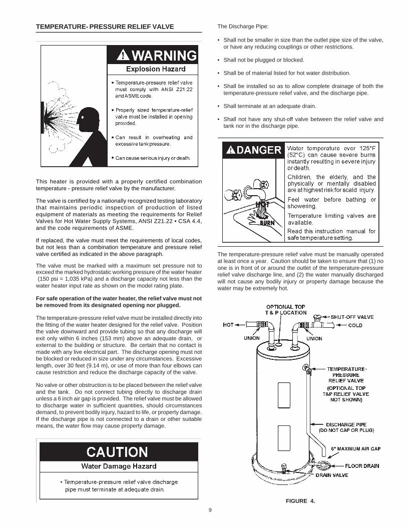
The temperature-pressure relief valve must be installed directly intothe fitting of the water heater designed for the relief valve. Positionthe valve downward and provide tubing so that any discharge willexit only within 6 inches (153 mm) above an adequate drain, orexternal to the building or structure. Be certain that no contact ismade with any live electrical part. The discharge opening must notbe blocked or reduced in size under any circumstances. Excessivelength, over 30 feet (9.14 m), or use of more than four elbows cancause restriction and reduce the discharge capacity of the valve.
No valve or other obstruction is to be placed between the relief valveand the tank. Do not connect tubing directly to discharge drainunless a 6 inch air gap is provided. The relief valve must be allowedto discharge water in sufficient quantities, should circumstancesdemand, to prevent bodily injury, hazard to life, or property damage.If the discharge pipe is not connected to a drain or other suitablemeans, the water flow may cause property damage.
The Discharge Pipe:
• Shall not be smaller in size than the outlet pipe size of the valve,or have any reducing couplings or other restrictions.
• Shall not be plugged or blocked.
• Shall be of material listed for hot water distribution.
• Shall be installed so as to allow complete drainage of both thetemperature-pressure relief valve, and the discharge pipe.
• Shall terminate at an adequate drain.
• Shall not have any shut-off valve between the relief valve andtank nor in the discharge pipe.
The temperature-pressure relief valve must be manually operatedat least once a year. Caution should be taken to ensure that (1) noone is in front of or around the outlet of the temperature-pressurerelief valve discharge line, and (2) the water manually dischargedwill not cause any bodily injury or property damage because thewater may be extremely hot.
FIGURE 4.
10
If after manually operating the valve, it fails to completely reset andcontinues to release water, immediately close the cold water inlet tothe water heater, follow the draining instructions, and replace thetemperature-pressure relief valve with a new one.
FILLING THE WATER HEATER
Never use this water heater unless it is completely full ofwater. To prevent damage to the tank and heating element,the tank must be filled with water. Water must flow from thehot water faucet before turning “ON” electrical supply to thewater heater. The manufacturer will not warrant any elementsdamaged by failure to follow instructions.
To fill the water heater with water:
1. Close the water heater drain valve by turning the handle tothe right (clockwise). The drain valve is on the lower front ofthe water heater.
2. Open the cold water supply valve to the water heater.NOTE: The cold water supply valve must be left openwhen the water heater is in use.
3. To insure complete filling of the tank, allow air to exit byopening the nearest hot water faucet. Allow water to rununtil a constant flow is obtained. This will let air out of thewater heater and the piping.
4. Check all water piping and connections for leaks. Repairas needed.
5. Never alter or modify the certified construction of the waterheater or its components, or bypass any safety features.Doing so voids all warranties.
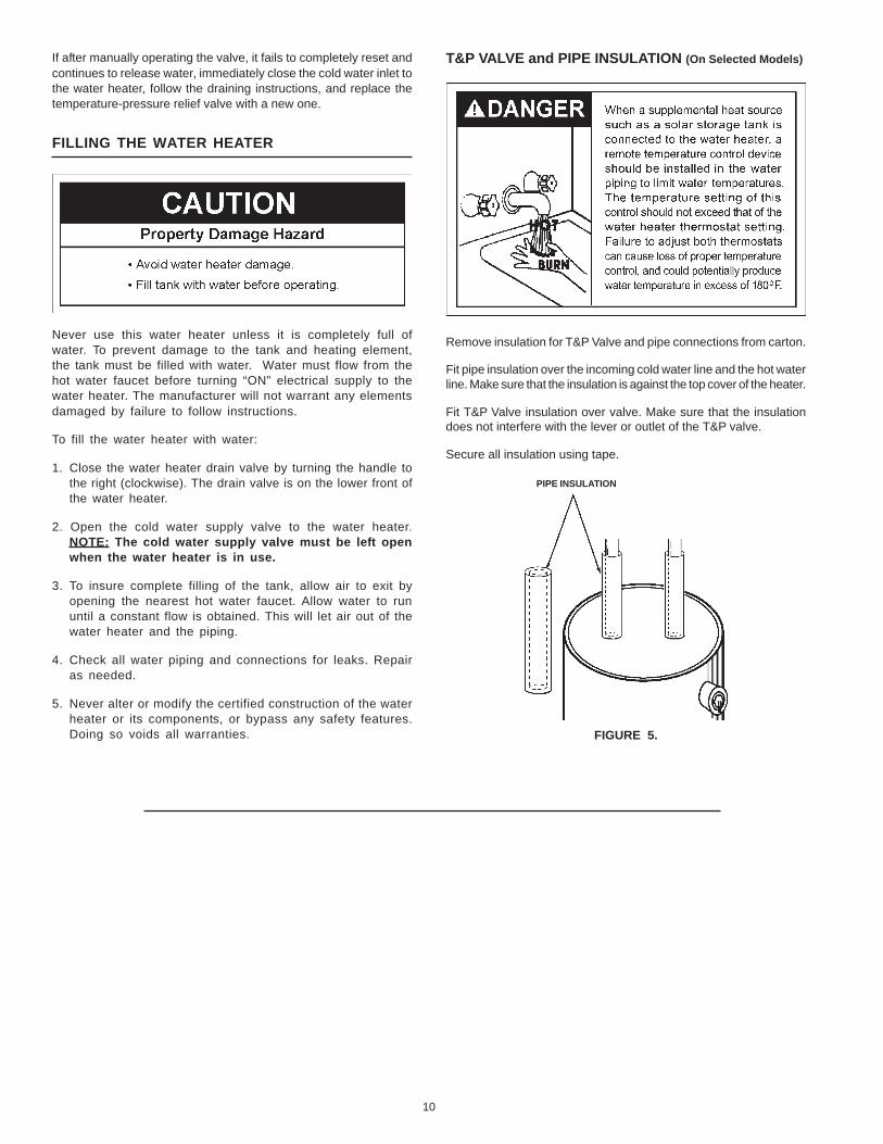
T&P VALVE and PIPE INSULATION (On Selected Models)
Remove insulation for T&P Valve and pipe connections from carton.
Fit pipe insulation over the incoming cold water line and the hot waterline. Make sure that the insulation is against the top cover of the heater.
Fit T&P Valve insulation over valve. Make sure that the insulationdoes not interfere with the lever or outlet of the T&P valve.
Secure all insulation using tape.
FIGURE 5.
PIPE INSULATION

11
WIRING DIAGRAMS
FOR ACTUAL WIRING CIRCUIT OF UNIT - REFERENCE CIRCUIT TYPE LISTED ON RATING PLATE.
FIGURE 6.

12
WIRING
Never use water heater unless it is completely full of water. To preventdamage to the tank and heating element, the tank must be filledwith water. Water must flow from the hot water faucet before turningon power.
You must provide all wiring of the proper size outside of the waterheater. You must obey local codes and electric companyrequirements when you install this wiring.
If you are not familiar with electric codes and practices, or if youhave any doubt, even the slightest doubt, in your ability to connect thewiring to this water heater, obtain the service of a competent electrician.Contact a local electrical contractor and/or the local electric utility.
WATER HEATERS EQUIPPED FOR ONE VOLTAGE ONLY: Thiswater heater is equipped for one type voltage only. Check the ratingplate near the bottom access panel for the correct voltage. DO NOTuse this water heater with any voltage other than the one shown onthe model rating plate. Failure to use the correct voltage can causeproblems which can result in DEATH, SERIOUS BODILY INJURY,OR PROPERTY DAMAGE. If you have any questions or doubtsconsult your electric company.
If wiring from your fuse box or circuit breaker box was aluminum foryour old water heater, replace it with copper wire. If you wish toreuse the existing aluminum wire, have the connection at the waterheater made by a competent electrician. Contact a local electricalcontractor and/or the local electric utility.
1. Provide a way to easily shut off the electric power when workingon the water heater. This could be with a circuit breaker or fuseblock in the entrance box or a separate disconnect switch.
2. Install and connect a circuit directly from the main fuse or circuitbreaker box. This circuit must be the right size and have its ownfuse or circuit breaker.
3. If metal conduit is used for the grounding conductor:
A. The grounding electrode conductor shall be of copper,aluminum, or copperclad aluminum. The material shall be ofone continuous length without a splice or joint.
B. Rigid metal conduit, intermediate metal conduit, or electrical,metallic tubing may be used for the grounding means if conduitor tubing is terminated in fittings approved for grounding.
C. Flexible metal conduit or flexible metallic tubing shall bepermitted for grounding if all the following conditions are met:
• The length in any ground return path does not exceed 6 feet.
• The circuit conductors contained therein are protected byovercurrent devices rated at 20 amperes or less.
• The conduit or tubing is terminated in fittings approved forgrounding.
For complete grounding details and all allowable exceptions, referto the current edition of the National Electrical Code NFPA 70.
4. A standard 1/2” conduit opening has been made in the waterheater junction box for the conduit connections.
5. Use wire nuts and connect the power supply wiring to the wiresinside the water heater’s junction box.
6. The water heater must be electrically “grounded” by the installer.A green ground screw has been provided on the water heater’sjunction box. Connect ground wire to this location.
7. Replace the wiring junction cover using the screw provided.
FIGURE 7.

13
TEMPERATURE ADJUSTMENT
To change the temperature setting:
NOTE: It is not necessary to adjust the upper thermostat. However, ifit is adjusted above the factory set point (120°F (49°C)) it isrecommended that it not be set higher than the lower thermostat setting.
1. Turn off the heater electrical supply. Do not attempt to adjustthermostat with power on.
2. Remove the thermostat access panels and covers from thethermostats. Do not remove the plastic personnel protectorscovering the thermostats.
3. Using a flat tip screwdriver, rotate the adjustment knob tothe desired temperature setting.
4. Replace the covers and access panels and turn on heaterelectrical supply.
TEMPERATURE SETTINGSIt is recommended that the dial be set lower whenever possible.
Temperature Time to Produce 2nd & 3rdSetting Degree Burns on Adult Skin
160°F (71°C) About 1/2 second150°F (66°C) About 1-1/2 seconds140°F (60°C) Less than 5 seconds130°F (54°C) About 30 seconds120°F (49°C) More than 5 minutes
FIGURE 8.
HOTTER WATER CAN SCALD: Water heaters are intendedto produce hot water. Water heated to a temperature whichwill satisfy space heating, clothes washing, dish washing,and other sanitizing needs can scald and permanently injureyou upon contact. Some people are more likely to bepermanently injured by hot water than others. These includethe elderly, children, the infirm, or physically/mentally disabled.If anyone using hot water in your home fits into one of thesegroups or if there is a local code or state law requiring acertain temperature water at the hot water tap, then youmust take special precautions. In addition to using the lowestpossible temperature setting that satisfies your hot waterneeds, a means such as a mixing valve, should be used atthe hot water taps used by these people or at the waterheater. Mixing valves are available from your local plumbingcontractor. Follow manufacturer’s instructions for installationof the valves. Before changing the factory setting on thethermostat, see Figure 8.
Never allow small children to use a hot water tap or to drawtheir own bath water. Never leave a child or handicapped personunattended in a bathtub or shower.
It is recommended that lower water temperatures be usedto avoid the risk of scalding. It is further recommended,in all cases, that the water temperature thermostat be setfor the lowest temperature which satisfies your hot waterneeds. This will also provide the most energy efficientoperation of the water heater. Thermostat(s) are factoryset at 120°F (49°C) unless specified differently by staterequirements.
KEEPING THE THERMOSTAT SETTING AT 120°F (49°C)WILL REDUCE THE RISK OF SCALDS.
Figure 8 shows the approximate time-to-burn relationship fornormal adult skin.
TEMPERATURE REGULATION

14
THERMAL EXPANSION
Water supply systems may, because of such events as high linepressure, frequent cut-offs, the effects of water hammer among others,have installed devices such as pressure reducing valves, check valves,back flow preventers, etc. to control these types of problems. Whenthese devices are not equipped with an internal by-pass, and noother measures are taken, the devices cause the water system to beclosed. As water is heated, it expands (thermal expansion) and closedsystems do not allow for the expansion of heated water.
The water within the water heater tank expands as it is heated andincreases the pressure of the water system. If the relieving point ofthe water heater’s temperature-pressure relief valve is reached, thevalve will relieve the excess pressure. The temperature-pressurerelief valve is not intended for the constant relief of thermalexpansion. This is an unacceptable condition and must be corrected.It is recommended that any devices installed which could create aclosed system have a by-pass and/or the system have an expansiontank or device to relieve the pressure built by thermal expansion inthe water system. Expansion tanks are available for ordering througha local plumbing contractor. Contact the local water heater supplieror service agency for assistance in controlling these situations.
STRANGE SOUNDS
Possible noises due to expansion and contraction of some metalparts during periods of heat-up and cool-down do not necessarilyrepresent harmful or dangerous conditions.
OPERATIONAL CONDITIONS
WATER ODOR
In each water heater there is installed at least one anode rod (seeparts sections) for corrosion protection of the tank. Certain waterconditions will cause a reaction between this rod and the water.The most common complaint associated with the anode rod is oneof a “rotten egg smell” in the hot water. This odor is derived fromhydrogen sulfide gas dissolved in the water. The smell is the resultof four factors which must all be present for the odor to develop:
A. A concentration of sulfate in the supply water.B. Little or no dissolved oxygen in the water.C. A sulfate reducing bacteria which has accumulated within the
water heater (this harmless bacteria is nontoxic to humans).D. An excess of active hydrogen in the tank. This is caused by the
corrosion protective action of the anode.
Smelly water may be eliminated or reduced in some water heatermodels by replacing the anode(s) with one of less active material, andthen chlorinating the water heater tank and all hot water lines. Contactthe local water heater supplier or service agency for further informationconcerning an Anode Replacement Kit and this chlorination treatment.If the smelly water persists after the anode replacement andchlorination treatment, we can only suggest that chlorination or aerationof the water supply be considered to eliminate the water problem.
Do not remove the anode leaving the tank unprotected. By doingso, all warranty on the water heater tank is voided.
“AIR” IN HOT WATER FAUCETS
HYDROGEN GAS: Hydrogen gas can be produced in a hot watersystem that has not been used for a long period of time (generallytwo weeks or more). Hydrogen gas is extremely flammable andexplosive. To prevent the possibility of injury under these conditions,we recommend the hot water faucet, located farthest away, beopened for several minutes before any electrical appliances whichare connected to the hot water system are used (such as adishwasher or washing machine). If hydrogen gas is present, therewill probably be an unusual sound similar to air escaping throughthe pipe as the hot water faucet is opened. There must be no smokingor open flame near the faucet at the time it is open.
HIGH WATER TEMPERATURE SHUT OFF SYSTEM
A non-adjustable high temperature limit control operatesbefore steam temperatures are reached. The high limit isin the same area as the upper thermostat and must bereset manually when it operates. BECAUSE THE HIGH LIMITOPERATES ONLY WHEN ABNORMALLY HIGH WATERTEMPERATURES ARE PRESENT, IT IS IMPORTANT THAT AQUALIFIED SERVICE AGENT BE CONTACTED TO DETERMINETHE REASON FOR OPERATION BEFORE RESETTING.
• Turn off the heater electrical supply. Do not attempt to resetthermostat with power on.
• Remove the screw(s) securing the outer door and remove door.
• Remove or fold up the insulation to expose the reset button.
• Reset the high limit by pushing in the red button marked “RESET”.
• Replace the insulation so that it completely covers the thermostatand element.
• Replace the outer door.
• Turn “ON” electric power to the water heater.
FOR YOUR INFORMATION
15
If after manually operating the valve, it fails to completely reset andcontinues to release water, immediately close the cold water inlet tothe water heater, follow the draining instructions, and replace thetemperature-pressure relief valve with a new one.
If the temperature-pressure relief valve on the appliance weeps ordischarges periodically, this may be due to thermal expansion. Youmay have a check valve installed in the water line or a water meterwith a check valve. Consult your local water supplier or serviceagency for further information. Do not plug or remove thetemperature-pressure relief valve.
DRAINING
The water heater should be drained if being shut down during freezingtemperatures. Also periodic draining and cleaning of sediment fromthe tank may be necessary.
1. Turn electrical supply “OFF”.
2. CLOSE the cold water inlet valve to the water heater.
3. OPEN a nearby hot water faucet and leave open to allow fordraining.
4. Connect a hose to the drain valve and terminate to an adequatedrain.
5. OPEN the water heater drain valve to allow for tank draining.
NOTE: If the water heater is going to be shut down anddrained for an extended period, the drain valve should beleft open with hose connected allowing water to terminateto an adequate drain.
6. Close the drain valve.
7. Follow the instructions in the “Filling the Water Heater” section.
THERMOSTAT REMOVAL / REPLACEMENT
ANODE ROD INSPECTION
The anode rod is used to protect the tank from corrosion. Most hot watertanks are equipped with an anode rod. The submerged rod sacrificesitself to protect the tank. Instead of corroding the tank, water ions attackand eat away the anode rod. This does not affect the water’s taste orcolor. The rod must be maintained to keep the tank in operating condition.
NOTE: Artificially softened water is exceedingly corrosive because theprocess substitutes sodium ions for magnesium and calcium ions. Theuse of a water softener may decrease the life of the water heater tank.
Anode deterioration depends on water conductivity, not necessarily watercondition. A corroded or pitted anode rod indicates high water conductivityand should be checked and/or replaced more often than an anode rodthat appears to be intact. Replacement of a depleted anode rod canextend the life of your water heater. Inspection should be conducted bya qualified technician, and at a minimum should be checked every threeyears. Typical (but not all) signs of a depleted anode rod are as follows:• The majority of the rods diameter is less than 3/8”• Significant sections of the support wire (approximately 1/3 or more
of the anode rod’s length) are visible.
If the anode rod shows signs of either or both it should be replaced.NOTE: Whether re-installing or replacing the anode rod, check forany leaks and immediately correct if found.
TEMPERATURE-PRESSURE RELIEF VALVE OPERATION
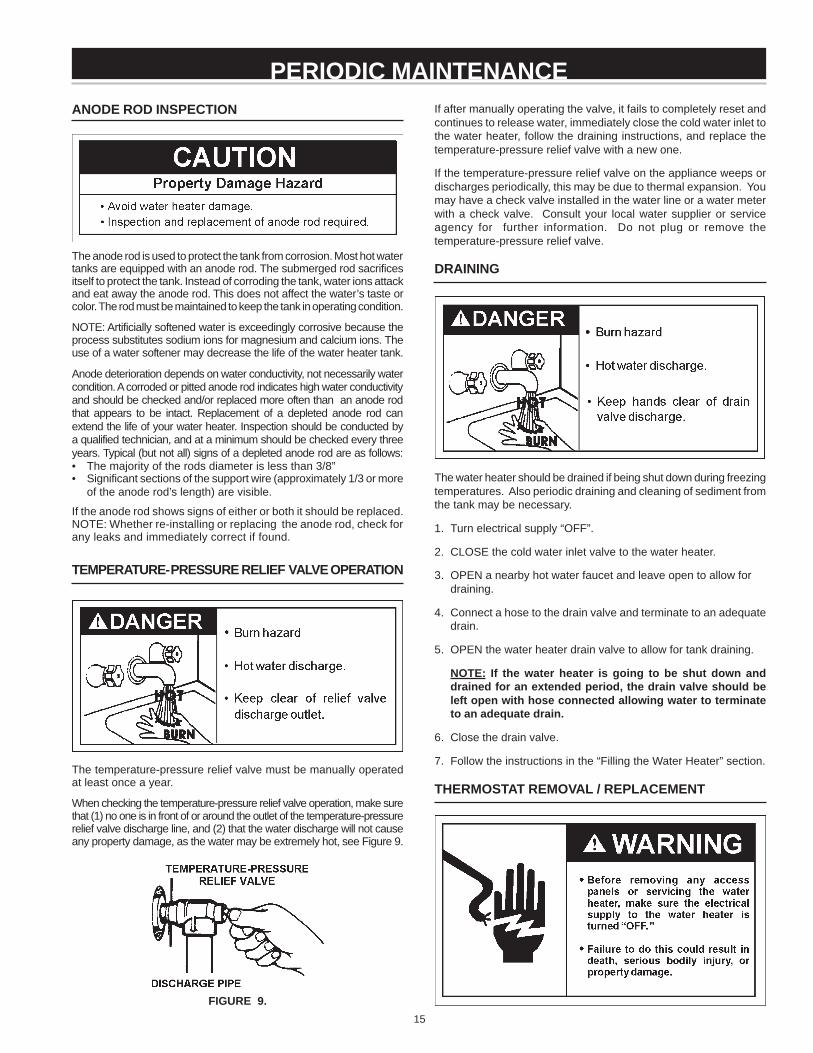
The temperature-pressure relief valve must be manually operatedat least once a year.
When checking the temperature-pressure relief valve operation, make surethat (1) no one is in front of or around the outlet of the temperature-pressurerelief valve discharge line, and (2) that the water discharge will not causeany property damage, as the water may be extremely hot, see Figure 9.
FIGURE 9.
PERIODIC MAINTENANCE

16
1. Turn “OFF” the electric power supply to the water heater.
2. Remove the outer door. Remove or fold up the insulation pad.
3. A. Models with lower thermostat without high limit: Liftout the tab as shown below to unclip the terminal coverfrom the thermostat. The terminal cover can now beremoved from the thermostat.
FIGURE 10.
B. Models with Upper or Lower Thermostat with HighLimit: Lift out the tab as shown below to unclip the terminalcover from the thermostat. The terminal cover can now beremoved from the thermostat.
FIGURE 11.
4. Disconnect wires from thermostat and slide out of the bracket.
5. Remove the thermostat from behind the thermostat bracket.
6. Place the new lower thermostat in the bracket making sure it fitsfirmly against the tank.
7. Attach the wires to the new thermostat.
NOTE: Some of the terminals may require straight-in wiringthrough an eye-opening. If wires are now looped, recut andstrip wire 3/8” to a straight length and insert.
8. Put plastic terminal cover back in place.
9. Replace the insulation to cover the thermostat.
10.Replace outer door then turn the electric power on.
ELEMENT CLEANING / REPLACEMENT
NOTE: These instructions are written for element cleaning andelement replacement for the lower element.
To remove the element from the tank in order to clean or replace it:
1. Before beginning turn “OFF” the electric power supply to the waterheater.
2. Turn off the water supply to the water heater at the water shut-offvalve or water meter, see Figure 12.
FIGURE 12.
3. Attach a hose to the water heater drain valve and put the otherend in a floor drain or outdoors. Open the water heater drainvalve. Open a nearby hot water faucet which will relieve pressurein the water heater and speed draining.
FIGURE 13.

17
The water passing out of the drain valve may be extremely hot. Toavoid being scald, make sure all connections are tight and that thewater flow is directed away from any person.
4. Remove the screw(s) securing the outer door, and remove door.
FIGURE 14.
5. Remove or fold up the insulation.
FIGURE 15.
6. A. Models with lower thermostat without high limit: Liftout the tab as shown below to unclip the terminal coverfrom the thermostat. The terminal cover can now beremoved from the thermostat.
FIGURE 16.
B. Models with Upper or Lower Thermostat with HighLimit: Lift out the tab as shown below to unclip the terminalcover from the thermostat. The terminal cover can now beremoved from the thermostat.
FIGURE 17.
7. Disconnect the two wires on the element and unscrew the oldelement from the tank.
FIGURE 18.
8. Clean the area around the element opening. Remove anysediment from or around the element opening and inside the tank.
9. If you are cleaning the element you have removed, do so byscraping or soaking in vinegar or a deliming solution.
NOTE: Replacement elements must (1) be the same voltage and(2) no greater wattage than listed on the model rating plateaffixed to the water heater.
10. A new gasket should be used in all cases to prevent a possiblewater leak. Place the new element gasket on the threaded sideof the cleaned or new element and screw into tank, securingtightly using an element wrench.
FIGURE 19.
18
11.Close the water heater drain valve by turning the handle to theright (clockwise). The drain valve is on the lower front of thewater heater.
12.Open the cold water supply valve to the water heater.
NOTE: The cold water supply valve must be left open whenthe water heater is in use.
13.To insure complete filling of the tank, allow air to exit by openingthe nearest hot water faucet. Allow water to run until a constantflow is obtained. This will let air out of the water heater and the piping.
Never use this water heater unless it is completely full of water. Toprevent damage to the tank and heating element, the tank must befilled with water. Water must flow from the hot water faucet beforeturning “ON” power. The manufacturer will not warrant any elementsdamaged by failure to follow instructions.
14.Check element for water leaks. If leakage occurs, tighten elementor repeat Steps 2 and 3, remove element and reposition gasket.Then repeat Steps 10 through 14.
15.Reconnect the two wires to the element and then check to makesure the thermostat remains firmly against the surface of the tank.
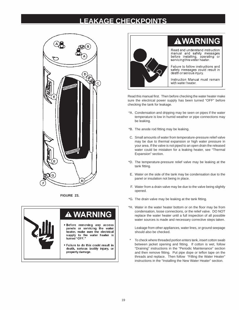
FIGURE 20.
16.Replace terminal cover on thermostat making sure the lockingtabs on the terminal cover are in place.
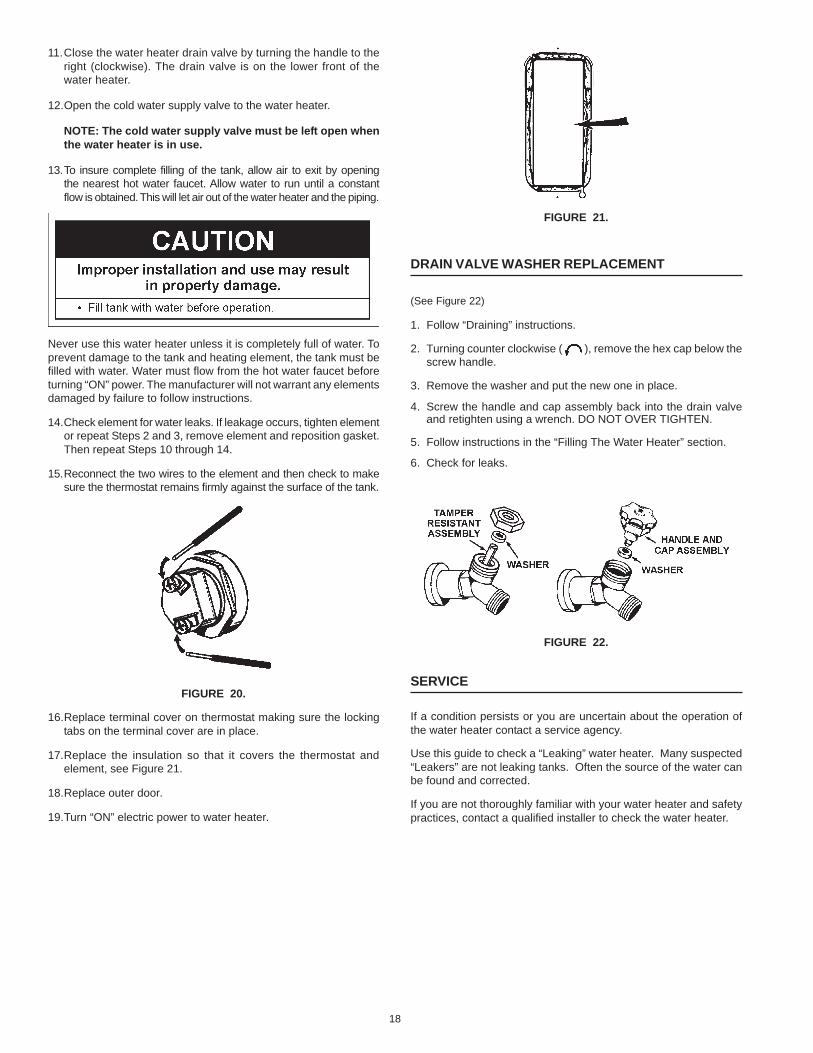
17.Replace the insulation so that it covers the thermostat andelement, see Figure 21.
18.Replace outer door.
19.Turn “ON” electric power to water heater.
FIGURE 21.
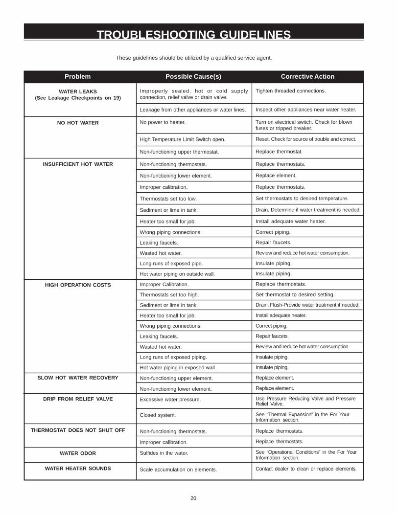
DRAIN VALVE WASHER REPLACEMENT
(See Figure 22)
1. Follow “Draining” instructions.
2. Turning counter clockwise ( ), remove the hex cap below thescrew handle.
3. Remove the washer and put the new one in place.
4. Screw the handle and cap assembly back into the drain valveand retighten using a wrench. DO NOT OVER TIGHTEN.
5. Follow instructions in the “Filling The Water Heater” section.
6. Check for leaks.
FIGURE 22.
SERVICE
If a condition persists or you are uncertain about the operation ofthe water heater contact a service agency.
Use this guide to check a “Leaking” water heater. Many suspected“Leakers” are not leaking tanks. Often the source of the water canbe found and corrected.
If you are not thoroughly familiar with your water heater and safetypractices, contact a qualified installer to check the water heater.
19
LEAKAGE CHECKPOINTS
Read this manual first. Then before checking the water heater makesure the electrical power supply has been turned “OFF” beforechecking the tank for leakage.
*A. Condensation and dripping may be seen on pipes if the watertemperature is low in humid weather or pipe connections maybe leaking.
*B. The anode rod fitting may be leaking.
C. Small amounts of water from temperature-pressure relief valvemay be due to thermal expansion or high water pressure inyour area. If the valve is not piped to an open drain the releasedwater could be mistaken for a leaking heater, see “ThermalExpansion” section.
*D. The temperature-pressure relief valve may be leaking at thetank fitting.
E. Water on the side of the tank may be condensation due to thepanel or insulation not being in place.
F. Water from a drain valve may be due to the valve being slightlyopened.
*G. The drain valve may be leaking at the tank fitting.
*H. Water in the water heater bottom or on the floor may be fromcondensation, loose connections, or the relief valve. DO NOTreplace the water heater until a full inspection of all possiblewater sources is made and necessary corrective steps taken.
Leakage from other appliances, water lines, or ground seepageshould also be checked.
* To check where threaded portion enters tank, insert cotton swabbetween jacket opening and fitting. If cotton is wet, follow“Draining” instructions in the “Periodic Maintenance” sectionand then remove fitting. Put pipe dope or teflon tape on thethreads and replace. Then follow “Filling the Water Heater”instructions in the “Installing the New Water Heater” section.
FIGURE 23.
20
Tighten threaded connections.
Inspect other appliances near water heater.
Turn on electrical switch. Check for blownfuses or tripped breaker.
Reset. Check for source of trouble and correct.
Replace thermostat.
Replace thermostats.
Replace element.
Replace thermostats.
Set thermostats to desired temperature.
Drain. Determine if water treatment is needed.
Install adequate water heater.
Correct piping.
Repair faucets.
Review and reduce hot water consumption.
Insulate piping.
Insulate piping.
Replace thermostats.
Set thermostat to desired setting.
Drain. Flush-Provide water treatment if needed.
Install adequate heater.
Correct piping.
Repair faucets.
Review and reduce hot water consumption.
Insulate piping.
Insulate piping.
Replace element.
Replace element.
Use Pressure Reducing Valve and PressureRelief Valve.
See “Thermal Expansion” in the For YourInformation section.
Replace thermostats.
Replace thermostats.
See “Operational Conditions” in the For YourInformation section.
Contact dealer to clean or replace elements.
Problem Possible Cause(s) Corrective Action
These guidelines should be utilized by a qualified service agent.
TROUBLESHOOTING GUIDELINES
Improperly sealed, hot or cold supplyconnection, relief valve or drain valve.
Leakage from other appliances or water lines.
No power to heater.
High Temperature Limit Switch open.
Non-functioning upper thermostat.
Non-functioning thermostats.
Non-functioning lower element.
Improper calibration.
Thermostats set too low.
Sediment or lime in tank.
Heater too small for job.
Wrong piping connections.
Leaking faucets.
Wasted hot water.
Long runs of exposed pipe.
Hot water piping on outside wall.
Improper Calibration.
Thermostats set too high.
Sediment or lime in tank.
Heater too small for job.
Wrong piping connections.
Leaking faucets.
Wasted hot water.
Long runs of exposed piping.
Hot water piping in exposed wall.
Non-functioning upper element.
Non-functioning lower element.
Excessive water pressure.
Closed system.
Non-functioning thermostats.
Improper calibration.
Sulfides in the water.
Scale accumulation on elements.
WATER LEAKS(See Leakage Checkpoints on 19)
NO HOT WATER
INSUFFICIENT HOT WATER
HIGH OPERATION COSTS
SLOW HOT WATER RECOVERY
DRIP FROM RELIEF VALVE
THERMOSTAT DOES NOT SHUT OFF
WATER ODOR
WATER HEATER SOUNDS
21
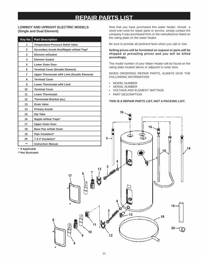
REPAIR PARTS LISTLOWBOY AND UPRIGHT ELECTRIC MODELS(Single and Dual Element)
Key No. Part Description1 Temperature-Pressure Relief Valve
2 Secondary Anode Rod/Nipple w/Heat Trap*
3 Element w/Gasket
4 Element Gasket
5 Lower Outer Door
6 Terminal Cover (Double Element)
7 Upper Thermostat w/Hi Limit (Double Element)
8 Terminal Cover
9 Lower Thermostat w/Hi Limit
10 Terminal Cover
11 Lower Thermostat
12 Thermostat Bracket (ea.)
13 Drain Valve
14 Primary Anode
15 Dip Tube
16 Nipple w/Heat Traps*
17 Upper Outer Door
18 Base Pan w/Side Drain
19 Pipe Insulation*
20 T & P Insulation*
** Instruction Manual
* If Applicable** Not Illustrated
Now that you have purchased this water heater, should aneed ever exist for repair parts or service, simply contact thecompany it was purchased from or the manufacturer listed onthe rating plate on the water heater.
Be sure to provide all pertinent facts when you call or visit.
Selling prices will be furnished on request or parts will beshipped at prevailing prices and you will be billedaccordingly.
The model number of your Water Heater will be found on therating plate located above or adjacent to outer door.
WHEN ORDERING REPAIR PARTS, ALWAYS GIVE THEFOLLOWING INFORMATION:
• MODEL NUMBER• SERIAL NUMBER• VOLTAGE AND ELEMENT WATTAGE• PART DESCRIPTION
THIS IS A REPAIR PARTS LIST, NOT A PACKING LIST.

22
REPAIR PARTS LIST
WHEN ORDERING REPAIR PARTS, ALWAYS GIVE THEFOLLOWING INFORMATION:
• MODEL NUMBER
• SERIAL NUMBER
• VOLTAGE AND ELEMENT WATTAGE
• PART DESCRIPTION
THIS IS A REPAIR PARTS LIST, NOT A PACKING LIST.
Now that you have purchased this water heater, should a needever exist for repair parts or service, simply contact the companyit was purchased from or the manufacturer listed on the ratingplate on the water heater.
Be sure to provide all pertinent facts when you call or visit.
Selling prices will be furnished on request or parts will beshipped at prevailing prices and you will be billed accordingly.
The model number of your Water Heater will be found on therating plate located above or adjacent to outer door.
Key No. Part Description1 Temperature-Pressure Relief Valve2 Outlet Nipple Assembly3 Inlet Nipple4 Junction Box Cover5 Upper and Lower Element6 Element Gasket7 Thermostat Bracket (ea.)8 Lower Thermostat9 Terminal Cover
10 Lower Thermostat w/Hi Limit11 Terminal Cover
12 Lower Outer Door
13 Upper Outer Door14 Upper Thermostat w/Hi/Limit15 Anode Rod16 Drain Valve17 Base Pan w/Side Drain18 Conduit Bracket19 Pipe Insulation*20 T & P Insulation*21 Dip Tube22 Plug** Instruction Manual
* If Applicable** Not Illustrated
COMPACT OR MANUFACTURED (MOBILE) HOME ELECTRIC MODELS
ACTUAL MODEL AND ILLUSTRATION MAY VARY DEPENDENT ON MODEL CAPACITY AND TYPE.SOME MODELS HAVE ALTERNATE INLET, OUTLET AND T&P VALVE LOCATIONS. THESEALTERNATE LOCATIONS ARE IDENTIFIED BY THE LABELING ON THE UNIT.

23
REPAIR PARTS LISTTABLE TOP ELECTRIC MODELS
Key No. Part Description1 Porcelain Top
2 Temperature and Pressure Relief Valve
3 Primary Anode Rod
4 Upper Thermostat w/Hi Limit
5 Dip Tube
6 Element w/Gasket
7 Element Gasket
8 Thermostat Bracket (ea.)
9 Terminal Cover
10 Outer Door (ea.)
11 Lower Thermostat w/Hi Limit
12 Terminal Cover
13 Lower Thermostat
14 Drain Access Door
15 Drain Valve
16 Toe Panel
** Instruction Manual
** Not Illustrated
Now that you have purchased this water heater, should a needever exist for repair parts or service, simply contact the companyit was purchased from or the manufacturer listed on the ratingplate on the water heater.
Be sure to provide all pertinent facts when you call or visit.
Selling prices will be furnished on request or parts will beshipped at prevailing prices and you will be billed accordingly.
The model number of your Water Heater will be found on therating plate located under or adjacent to outer door.
WHEN ORDERING REPAIR PARTS, ALWAYS GIVE THEFOLLOWING INFORMATION:
• MODEL NUMBER
• SERIAL NUMBER
• VOLTAGE AND ELEMENT WATTAGE
• PART DESCRIPTION
THIS IS A REPAIR PARTS LIST, NOT A PACKING LIST.
24
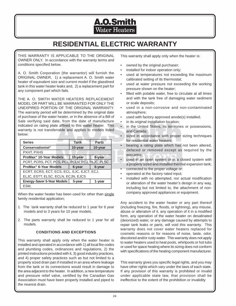
RESIDENTIAL ELECTRIC WARRANTYTHIS WARRANTY IS APPLICABLE TO THE ORIGINALOWNER ONLY. In accordance with the warranty terms andconditions specified below.
A. O. Smith Corporation (the warrantor) will furnish theORIGINAL OWNER, 1) a replacement A. O. Smith waterheater of equivalent size and current model if the glasslinedtank in this water heater leaks and, 2) a replacement part forany component part which fails.
THE A. O. SMITH WATER HEATERS REPLACEMENTMODEL OR PART WILL BE WARRANTED FOR ONLY THEUNEXPIRED PORTION OF THE ORIGINAL WARRANTY.The warranty period will be determined by the original dateof purchase of the water heater, or in the absence of a Bill ofSale verifying said date, from the date of manufactureindicated on rating plate affixed to this water heater. Thiswarranty is not transferrable and applies to models listedbelow:
When the water heater has been used for other than singlefamily residential application;
1. The tank warranty shall be reduced to 1 year for 6 yearmodels and to 3 years for 10 year models.
2. The parts warranty shall be reduced to 1 year for allmodels.
CONDITIONS AND EXCEPTIONS
This warranty shall apply only when the water heater isinstalled and operated in accordance with 1) all local fire codesand plumbing codes, ordinances and regulations, 2) theprinted instructions provided with it, 3) good industry practices,and 4) proper safety practices such as but not limited to aproperly sized drain pan if installed in an area where leakagefrom the tank or its connections would result in damage tothe area adjacent to the heater. In addition, a new temperatureand pressure relief valve, certified by the Canadian GasAssociation must have been properly installed and piped tothe nearest drain.
This warranty shall apply only when the heater is:
• owned by the original purchaser;• installed for indoor operation only;• used at temperatures not exceeding the maximum
calibrated setting of its thermostat;• used at water pressure not exceeding the working
pressure shown on the heater;• filled with potable water, free to circulate at all times
and with the tank free of damaging water sedimentor scale deposits;
• used in a non-corrosive and non-contaminatedatmosphere;
• used with factory approved anode(s) installed;• in its original installation location;• in the United States, its territories or possessions,
and Canada;• sized in accordance with proper sizing techniques
for residential water heaters;• bearing a rating plate which has not been altered,
defaced or removed except as required by thewarrantor;
• used in an open system or in a closed system witha properly sized and installed thermal expansion tank;
• connected to the proper voltage or:• operated at the factory rated input;• installed with no attempted, nor actual modification
or alteration of the water heater’s design in any way,including but not limited to, the attachment of non-company approved appliances or equipment.
Any accident to the water heater or any part thereof(including freezing, fire, floods, or lightning), any misuse,abuse or alteration of it, any operation of it in a modifiedform, any operation of the water heater on desalinated(deionized) water, or any damage caused by attempts torepair tank leaks or parts, will void this warranty. Thiswarranty does not cover water heaters replaced forcosmetic reasons or for reasons of noise, taste, odor,discolored and/or rusty water. This warranty does not applyto water heaters used to heat pools, whirlpools or hot tubsor used for space heating where its sizing does not conformwith specifications of the heating component manufacturer.
This warranty gives you specific legal rights, and you mayhave other rights which vary under the laws of each state.If any provision of this warranty is prohibited or invalidunder applicable state law, that provision shall beineffective to the extent of the prohibition or invalidity
Series Tank PartsConservationist® 10-year 10-yearPXHT, PXHSProMax® 10-Year Models 10-year 6-yearPCRT, PCRS, PCT, PCS, PCL, PCLN, PCJ, PLJC, PLSCProMax® 6-Year Models 6-year 6-yearECRT, ECRS, ECT, ECS, ECL, EJC, EJCT, ECJ,ELJC, ESTT, ELSC, ECLN, ECJN, EJCSEnergy-Saver 5-Year Models 5-year 1-yearESM,

25
without invalidating the remainder of the affected provisionor the other provisions of this warranty.
SERVICE AND LABOR RESPONSIBILITY
UNDER THIS LIMITED WARRANTY, THE WARRANTORWILL PROVIDE ONLY A REPLACEMENT WATERHEATER OR PART THEREOF. THE OWNER ISRESPONSIBLE FOR ALL OTHER COSTS. Such costsmay include but are not limited to:
a. Labor charges for service, removal, or reinstallationof the water heater or part thereof.
b. Shipping and delivery charges for forwarding the newwater heater or replacement part from the nearestdistributor and returning the claimed defective heateror part to such distributor.
c. All cost necessary or incidental for handling andadministrative charges, and for any materials and/orpermits required for installation of the replacementheater or part.
LIMITATION ON IMPLIED WARRANTIES
Impl ied warrant ies, including any warranty ofmerchantability imposed on the sale of this heater understate law are limited to one year duration for the heateror any of its parts. Some states do not allow limitationson how long an implied warranty lasts, so the abovelimitations may not apply to you.
CLAIM PROCEDURE
Any claim under this warranty should be initiated with thedealer who sold the heater, or with any other dealerhandling the warrantor’s products. If this is not practical,the owner should contact: A.O. Smith Corporation,500 Tennessee Waltz Parkway, Ashland City, TN 37015.Phone: 1.800.323.2636 or visit our website:www.hotwater.com.
For Canadian customers contact: A.O. Smith EnterprisesLTD., P.O. Box 310, 768 Erie Street, Stratford, OntarioN5A6T3 or phone: 1.800.265.8520
Replacement Parts may be ordered through authorizedservicers or distributors. Refer to your local Yellow Pagesfor where to call or contact A.O. Smith Corporation,500 Tennessee Waltz Parkway, Ashland City, TN 37015.Phone: 1.800.433.2545 or visit our website at:www.hotwater.com/parts.
The warrantor will only honor replacement with identicalor similar water heater or parts thereof which aremanufactured or distributed by the warrantor.
Dealer replacements are made subject to in-warrantyvalidation by warrantor.
PROOF OF PURCHASE AND PROOF OF INSTALLATIONDATE ARE REQUIRED TO SUPPORT WARRANTY CLAIMFROM ORIGINAL OWNER. THIS FORM DOES NOTCONSTITUTE PROOF OF PURCHASE OR PROOF OFINSTALLATION.
DISCLAIMERS
NO EXPRESSED WARRANTY HAS BEEN OR WILL BEMADE IN BEHALF OF THE WARRANTOR WITHRESPECT TO THE MERCHANTABILITY OF THE HEATEROR THE INSTALLATION, OPERATION, REPAIR ORREPLACEMENT OF THE HEATER OR PARTS. THEWARRANTOR SHALL NOT BE RESPONSIBLE FORWATER DAMAGE, LOSS OF USE OF THE UNIT,INCONVENIENCE, LOSS OR DAMAGE TO PERSONALPROPERTY, OR OTHER CONSEQUENTIAL DAMAGE.THE WARRANTOR SHALL NOT BE LIABLE BY VIRTUEOF THIS WARRANTY OR OTHERWISE FOR DAMAGETO ANY PERSONS OR PROPERTY, WHETHER DIRECTOR INDIRECT, AND WHETHER ARISING IN CONTRACTOR IN TORT.
Should governmental regulations or industry standardsprohibit the Manufacturer from furnishing a comparablemodel replacement under this warranty, the Owner will befurnished with the closest comparable water heater meetingthe then current governmental regulations and industrystandards. A supplementary fee may be assessed to coverthe additional cost associated with the changes made tomeet applicable regulations and standards.
IMPORTANT INFORMATION
Model Number _______________________________
Serial Number _______________________________
INSTALLATION INFORMATION
Date Installed _______________________________
Company’s Name ____________________________
Street or P.O. Box ____________________________
City, State, and Zip Code _______________________
Phone Number _______________________________
Plumber’s Name _____________________________
www.aosmithwaterheaters.com

26
NOTES:________________________________________________________________________________________________________________________________________________________________________________________________________________________________________________________________________________________________________________________________________________________________________________________________________________________________________________________________________________________________________________________________________________________________________________________________________________________________________________________________________________________________________________________________________________________________________________________________________________________________________________________________________________________________________________________________________________________________________________________________________________________________________________________________________________________________________________________________________________________________________________________________________________________________________________________________________________________________________________________________________________________________________________________________________________________________________________________________________________________________________________________________________________________________________________________________________________________________________________________________________________________________

27
NOTES:________________________________________________________________________________________________________________________________________________________________________________________________________________________________________________________________________________________________________________________________________________________________________________________________________________________________________________________________________________________________________________________________________________________________________________________________________________________________________________________________________________________________________________________________________________________________________________________________________________________________________________________________________________________________________________________________________________________________________________________________________________________________________________________________________________________________________________________________________________________________________________________________________________________________________________________________________________________________________________________________________________________________________________________________________________________________________________________________________________________________________________________________________________________________________________________________________________________________________________________________________________________________

28
www.aosmithwaterheaters.com