instruction manual - radio control cars, trucks, airplanes, boats & drones | tower …€¦ ·...
TRANSCRIPT
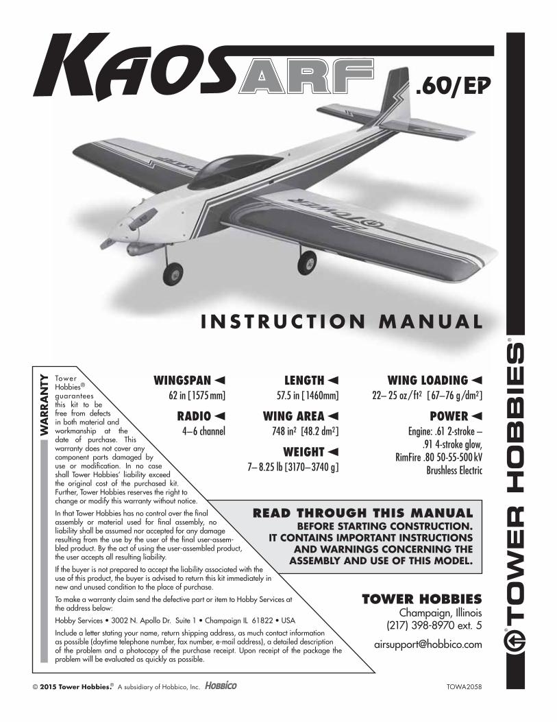
READ THROUGH THIS MANUALBEFORE STARTING CONSTRUCTION.
IT CONTAINS IMPORTANT INSTRUCTIONS AND WARNINGS CONCERNING THE
ASSEMBLY AND USE OF THIS MODEL.
WEIGHT7– 8.25 lb [3170–3740 g]
WING LOADING22– 25 oz/ft2 [67–76 g/dm2]
RADIO4–6 channel
Tower Hobbies® guarantees this kit to be free from defects in both material and workmanship at the date of purchase. This warranty does not cover any component parts damaged by use or modification. In no case shall Tower Hobbies’ liability exceed the original cost of the purchased kit. Further, Tower Hobbies reserves the right to change or modify this warranty without notice.
In that Tower Hobbies has no control over the final assembly or material used for final assembly, no liability shall be assumed nor accepted for any damage resulting from the use by the user of the final user-assem-bled product. By the act of using the user-assembled product, the user accepts all resulting liability.
If the buyer is not prepared to accept the liability associated with the use of this product, the buyer is advised to return this kit immediately in new and unused condition to the place of purchase.
To make a warranty claim send the defective part or item to Hobby Services at the address below:
Hobby Services • 3002 N. Apollo Dr. Suite 1 • Champaign IL 61822 • USA
Include a letter stating your name, return shipping address, as much contact information as possible (daytime telephone number, fax number, e-mail address), a detailed description of the problem and a photocopy of the purchase receipt. Upon receipt of the package the problem will be evaluated as quickly as possible.
WA
RR
AN
TY
TOWA2058© 2015 Tower Hobbies.® A subsidiary of Hobbico, Inc.
®®
TOWER HOBBIESChampaign, Illinois
(217) 398-8970 ext. 5
WINGSPAN62 in [1575 mm]
WING AREA748 in2 [48.2 dm2]
LENGTH57.5 in [1460mm]
I N S T R U C T I O N M A N UA L
POWEREngine: .61 2-stroke –
.91 4-stroke glow,RimFire .80 50-55-500 kV
Brushless Electric
2
INTRODUCTION
Congratulations and thank you for purchasing the Tower Hobbies Kaos .60 ARF. Those familiar with the original Kaos design dating back to the early ‘70s (or earlier!) will have nostalgic memories while enjoying a new flying experience. Newer pilots unfamiliar with the Kaos’ history will enjoy a good-flying model just the same! With its Pattern pedigree the Kaos is a smooth, easy flyer more than capable of maneuvers with grace and precision!
For the latest technical updates or manual corrections to the Kaos .60 ARF visit the Tower Hobbies web site at towerhobbies.com and visit the page for the Kaos .60. If there is new technical information or changes to this model a “tech notice” box will appear on the page.
Academy of Model Aeronautics
If you are not already a member of the AMA, please join! The AMA is the governing body of model aviation and membership provides liability insurance coverage, protects modelers’ rights and interests and is required to fly at most R/C sites.
Academy of Model Aeronautics5151 East Memorial DriveMuncie, IN 47302-9252
Tele. (800) 435-9262Fax (765) 741-0057
Or via the Internet at: http://www.modelaircraft.org
IMPORTANT!!! Two of the most important things you can do to preserve the radio controlled aircraft hobby are to avoid flying near full-scale aircraft and avoid flying near or over groups of people.
SAFETY PRECAUTIONS
Protect Your Model, Yourself & Others…Follow These Important Safety Precautions
1. Your Kaos should not be considered a toy, but rather a sophisticated, working model that functions very much like a full-size airplane. Because of its performance capabilities, the Sequence, if not assembled and operated correctly, could possibly cause injury to yourself or spectators and damage to property.
2. You must assemble the model according to the instructions. Do not alter or modify the model, as doing so may result in an unsafe or unflyable model. In a few cases the instructions may differ slightly from the photos. In those instances the written instructions should be considered as correct.
3. You must take time to build straight, true and strong.
4. You must use an R/C radio system that is in good condition, a correctly sized engine, and other components as specified in this instruction manual. All components must be correctly installed so that the model operates correctly on the ground and in the air. You must check the operation of the model and all components before every flight.
5. If you are not an experienced pilot or have not flown this type of model before, we recommend that you get the assistance of an experienced pilot in your R/C club for your first flights. If you’re not a member of a club, your local hobby shop has information about clubs in your area whose membership includes experienced pilots.
6. While this kit has been flight tested to exceed normal use, if the plane will be used for extremely high stress flying, such as racing, or if an engine larger than one in the recommended range is used, the modeler is responsible for taking steps to reinforce the high stress points and/or substituting hardware more suitable for the increased stress.
TABLE OF CONTENTS
INTRODUCTION . . . . . . . . . . . . . . . . . . . . . . . . . . . . . . . . 2
Academy of Model Aeronautics . . . . . . . . . . . . . . . . 2
SAFETY PRECAUTIONS . . . . . . . . . . . . . . . . . . . . . . . . . 2
ADDITIONAL ITEMS REQUIRED . . . . . . . . . . . . . . . . . . 3
Glow Engine . . . . . . . . . . . . . . . . . . . . . . . . . . . . . . . . 3
Brushless Electric Motor . . . . . . . . . . . . . . . . . . . . . . 3
Radio / Servos . . . . . . . . . . . . . . . . . . . . . . . . . . . . . . 3
ADHESIVES, HARDWARE
& OTHER ACCESSORIES . . . . . . . . . . . . . . . . . . . . . 4
KIT INSPECTION . . . . . . . . . . . . . . . . . . . . . . . . . . . . . . . 4
KIT CONTENTS. . . . . . . . . . . . . . . . . . . . . . . . . . . . . . . . . 4
PREPARATION . . . . . . . . . . . . . . . . . . . . . . . . . . . . . . . . . 5
ASSEMBLE THE WING . . . . . . . . . . . . . . . . . . . . . . . . . . 5
FUSELAGE . . . . . . . . . . . . . . . . . . . . . . . . . . . . . . . . . . . . 7
Mount the Tail . . . . . . . . . . . . . . . . . . . . . . . . . . . . . . . 7
Mount the Nose Gear . . . . . . . . . . . . . . . . . . . . . . . . . 8
MOUNT THE ENGINE OR MOTOR . . . . . . . . . . . . . . . . . 9
Glow Engine . . . . . . . . . . . . . . . . . . . . . . . . . . . . . . . . 9
Electric Motor . . . . . . . . . . . . . . . . . . . . . . . . . . . . . . 14
FINAL ASSEMBLY . . . . . . . . . . . . . . . . . . . . . . . . . . . . . 16
Final Radio Installation. . . . . . . . . . . . . . . . . . . . . . . 16
Prepare the Model for Flight . . . . . . . . . . . . . . . . . . 18
Balance the Model Laterally . . . . . . . . . . . . . . . . . . 18
PREFLIGHT . . . . . . . . . . . . . . . . . . . . . . . . . . . . . . . . . . . 18
ENGINE/MOTOR SAFETY PRECAUTIONS . . . . . . . . . 18
Battery Precautions . . . . . . . . . . . . . . . . . . . . . . . . . 19
Range Check . . . . . . . . . . . . . . . . . . . . . . . . . . . . . . 20
AMA SAFETY CODE. . . . . . . . . . . . . . . . . . . . . . . . . . . . 20
General . . . . . . . . . . . . . . . . . . . . . . . . . . . . . . . . . . . 20
Radio Control . . . . . . . . . . . . . . . . . . . . . . . . . . . . . . 20
FLYING. . . . . . . . . . . . . . . . . . . . . . . . . . . . . . . . . . . . . . . 20

3
7. WARNING: The cowl included in this kit is made of fiberglass, the fibers of which may cause eye, skin and respiratory tract irritation. Never blow into the cowl to remove fiberglass dust, as the dust will blow back into your eyes. Always wear safety goggles, a particle mask and rubber gloves when grinding, drilling and sanding fiberglass parts. Vacuum the parts and the work area thoroughly after working with fiberglass parts.
We, as the kit manufacturer, provide you with a top qual-ity, thoroughly tested kit and instructions, but ultimately the quality and fl yability of your fi nished model depends on how you build it; therefore, we cannot in any way guarantee the performance of your completed model, and no representations are expressed or implied as to the performance or safety of your completed model.
ADDITIONAL ITEMS REQUIRED
Glow Engine
The Kaos is suited for a .60 2-stroke or .91 4-stroke. The O.S. Max .65AX (OSMG0558) is illustrated in this manual. If side-mounting the engine as shown, the short muffler extension will also be required (OSMG2582).
OTHER ACCESSORIES IF USING A GLOW ENGINE
❍ 1/4" [6.4mm] R/C foam rubber (HCAQ1000)
❍ Great Planes Dead Center Hole Locator (GPMR8130)
❍ 4 mm tap and drill set (GPMR8113)
❍ Suitable propeller as specified by the engine manufacturer
Brushless Electric Motor
The Kaos flies superbly with a 50-55-500 kV RimFire .80 (GPMG4740), 14"–15" propellers and a 6S LiPo in the 4000 mAh range.
ELECTRONIC SPEED CONTROL
Any 75A ESC for brushless motors is suitable, but the Castle Creations Edge 75 (CSEM0101) is recommended because it has a heat sink and can be mounted to the bottom of the motor mount box inside the cowl. Other ESCs possibly may not fit in the cowl, but could be mounted in the fuselage if adequate airflow is provided. A 6" servo extension (TACM2092) will also be required to extend the signal lead from the ESC to the receiver.
BATTERIES
You may use a 6S battery, or two 3S batteries connected in series. This configuration depends on your charger capabilities and what batteries you may already have available.
6S BATTERIES
❍ Flight Power 6S 4350mAh 30C (FPWP3436)❍ Flight Power 6S 3800mAh 30C (FPWP3386)❍ Flight Power 6S 3800mAh 70C (FPWP7386)❍ Flight Power 6S 4400mAh 70C (FPWP7446)
3S BATTERIES (2 required)
❍ Flight Power 3S 4350mAh 30C (FPWP3433)
❍ Flight Power 3S 4000mAh 25C (FPWP2403)
❍ Flight Power 3S 3800mAh 30C (FPWP3383)
❍ Using two 3S batteries also requires a Series connector (GPMM3143)
OTHER ACCESSORIES IF ELECTRIC POWERED
❍ Double-sided adhesive-back Velcro is used to help secure the battery (GPMQ4480)
❍ 3/16" shrink tubing (DUBM2187) is required after soldering the 4mm bullet connectors (included with the RimFire motor) to the ESC
❍ A male “T” style battery connector is also required to connect the ESC to the battery (HCAM4010)
❍ (4) #4 x 3/8" screws (for Castle Creations Edge ESC mounting)
SUITABLE PROPELLERS FOR RIMFIRE .80
❍ APC 14 x 10E (APCQ1409)
❍ APC 15 x 7E (APCQ1830)
❍ APC 15 x 8E (APCQ4013)
Refer to page 19 for additional guidance on propeller selection.
IMPORTANT: Before connecting multiple battery packs with adapter plugs, refer to the Battery Precautions on page 19.
LiPo BATTERY CHARGER
To charge a 6S 4000mAh LiPo recommended for the Kaos at the minimum charge rate of 1C, a charger capable of at least 100 watts output is required (6S x 4.2 V/cell = 25.2V x 4A = 100W). The Triton2 EQ (GPMM3156) is rated to 120W DC and 100W AC so it is a suitable for charger. A dual-output charger of at least 50W per output would also be suitable if using two 3S batteries in series.
Radio / Servos
A minimum 4-channels is required to fly the Kaos. The Tactic TTX650 is recommended because of its versatility, computer programming and multiple model memory.
❍ Tactic TTX650 6-channel programmable radio (TACJ2650)
❍ Tactic TR625 6-chanel receiver (TACJ0625)
❍ On-off receiver switch (TACM2000)
A 2S, 1100 mAh LiFe pack (HCAM6416) was used to power the receiver and servos. If using a receiver and servos other than those suggested, make sure they are compatible with the higher voltage of a LiFe battery, or use a different receiver battery. The Triton2 EQ also has LiFe charge capabilities.
Tactic TSX25 mini digital high-speed 2 ball bearing servos (TACM0225) are illustrated in the instruction manual. Three or 4 servos will be required depending on whether you power your Kaos with an electric motor or glow engine. Standard-

4
size servos may also be used, but the servo cutouts will have to be enlarged.
If mixing the aileron servos through the radio electronically:
❍ (4) 6" [150 mm] servo extensions (TACM2092) are required for the aileron servos.
If connecting the servos with a Y-harness:
❍ (2) 6" [150 mm] servo extensions (TACM2092) and a Y-harness (FTM4130) are required for the aileron servos.
ADHESIVES, HARDWARE
& OTHER ACCESSORIES
Other than common hobby tools, here is a list of the rest of the items required:
❍ If using an electric motor, 30-minute epoxy is recommended for gluing together the motor mount box (GMR6043)
❍ Threadlocker thread locking cement (GPMR6060)
❍ Thin CA (GPMR6001)
❍ Medium CA (GPMR6007)
❍ CA applicator tips (HCAR3780)
❍ A Robart Super Stand II (ROBP1402) is also helpful for working on your Kaos .60.
❍ A covering iron with a cover sock may be required for tightening and re bonding the covering to the model that may have loosened between the time the plane was manufactured and the time the model was removed from the box. The 21st Century iron is preferred because of its long cord, contoured shoe and precisely adjustable temperature range:
❍ Coverite 21st Century Sealing Iron (COVR2700)
❍ Coverite 21st Century Cover Sock (COVR2702)
KIT INSPECTION
Before starting to build, take an inventory of this kit to make sure it is complete, and inspect the parts to make sure they are of acceptable quality. If any parts are missing or are not of acceptable quality, or if you need assistance with assembly, contact Product Support. When reporting defective or missing parts, use the part names exactly as they are written in the Kit Contents list.
Hobbico Product Support3002 N. Apollo Drive, Suite 1 Ph: (217) 398-8970, ext. 5Champaign, IL 61822 Fax: (217) 398-7721
E-mail: [email protected]
Order No. Description
REPLACEMENT PARTS LIST
TOWA2070TOWA2071TOWA2072TOWA2073TOWA2074TOWA2075TOWA2076TOWA2077TOWA2078TOWA2079TOWA2080
Wing SetFuselage Set (without canopy hatch)Tail SetLanding Gear SetCanopy HatchWing Joiner Tube2-3/4" SpinnerDecalsEP Motor Mount Box Kit1/4-20 x 1" Wing Bolts (2)Cowl
KIT CONTENTS
1. Fuselage & Canopy Hatch
2. Wings
3. Cowl
4. EP Motor Mount Box (provided
unassembled)
5. Fuel Tank Assembly
6. Fuel Line
7. Engine Mount
8. 2-3/4" Spinner
9. Wing Tube
10. Horizontal Stabilizer
11. Vertical Stabilizer
12. Hardware Set A
13. Hardware Set B
14. Wheels
15. Landing Gear
1
89
7
10
12
1113
14
15
6
2
2
4
3
5
5
PREPARATION
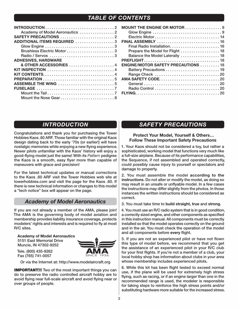
❏ 1. Use a covering iron set to about 300°F with a covering sock to go over the model where necessary to shrink the covering and remove any wrinkles and to bond the covering to wood underneath. If you will be using a glow engine, pay special attention to the edges of the covering around the firewall to make sure it is thoroughly sealed down so fuel won’t get in.
NOTE: This covering material requires less heat than you may be used to – too much heat may cause seams and edges to draw away from each other causing wavy, uneven edges or exposed balsa.
❏ 2. If powering your Kaos with a glow engine, apply a film of epoxy or CA to seams around the firewall.
❏ 3. Give a generous tug on all control surfaces to check the hinges. Add thin CA where necessary to any loose hinges. Residual CA or any CA “fog” can be removed with a paper towel dampened with CA debonder.
ASSEMBLE THE WING
❏ 1. Attach a 6" [150mm] servo extension to each aileron servo and secure with the included 1-1/2" [40mm] shrink tubing.
6
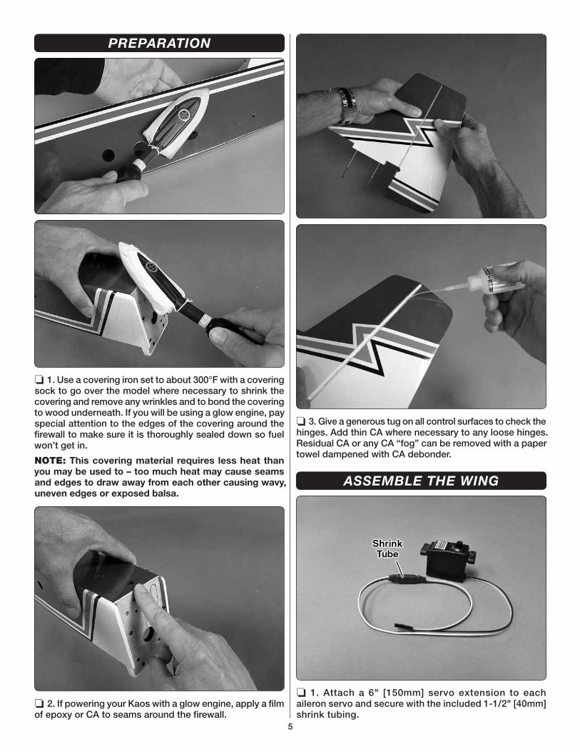
Enlarge the aileron servomount for standard servos.
Cut Out
❏ 2. If necessary, enlarge the servo cutouts to fit your servos.
❏ 3. Drill 1/16" [1.6mm] holes for the servo screws and mount the servos.
❏ 4. Using care not to drill all the way through the ailerons, drill 1/16" [1.6mm] holes for the aileron horn mounting screws, then connect the aileron servo to the aileron with the hardware shown.
❏ 5. Temporarily remove the screws and horns from the ailerons. Add a few drops of thin CA into the holes to harden them, allow the CA to fully harden, then re mount the horns with the screws.
❏ 6. Mount the 3" [75mm] wheels to the main landing gear wire with the collars and a drop of threadlocker on the set screws.
❏ 7. Using the landing gear straps as a guide, drill 3/32" [2.4mm] holes into the landing gear rails.
❏ 8. Using a No. 1 Phillips screwdriver, mount the main landing gear to the wing with the straps and M3x10 screws.
7
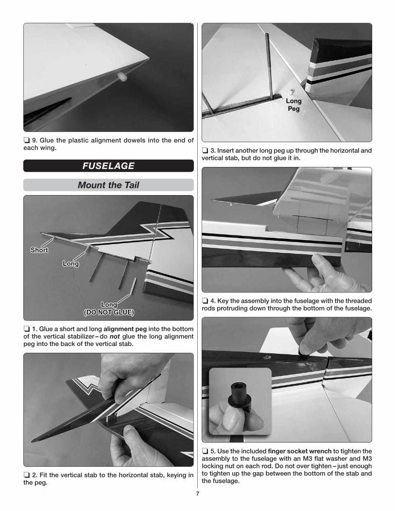
❏ 9. Glue the plastic alignment dowels into the end of each wing.
FUSELAGE
Mount the Tail
❏ 1. Glue a short and long alignment peg into the bottom of the vertical stabilizer – do not glue the long alignment peg into the back of the vertical stab.
❏ 2. Fit the vertical stab to the horizontal stab, keying in the peg.
❏ 3. Insert another long peg up through the horizontal and vertical stab, but do not glue it in.
❏ 4. Key the assembly into the fuselage with the threaded rods protruding down through the bottom of the fuselage.
❏ 5. Use the included finger socket wrench to tighten the assembly to the fuselage with an M3 flat washer and M3 locking nut on each rod. Do not over tighten – just enough to tighten up the gap between the bottom of the stab and the fuselage.

8
Mount the Nose Gear
❏ 1. If installing an electric motor, cut the rest of the way through the partial cut in the firewall for the battery wires from the ESC. Also cut the covering from the hole in the bottom of the fuselage where shown.
❏ 2. Assemble the nose gear assembly as shown – be certain to lightly wet the threads of the screws with threadlocker.
❏ 3. Cut the nose wheel pushrod guide tube to a length of 14-1/2" [370mm], then insert it up through the fuselage where shown – it may be necessary to trim the bottom of the fuel tank plate block to accommodate the tube.
Cut OffThreaded
End
Nose-SteeringPushrod
17-1/2' [445 mm]
90°
❏ 4. Make a 17-1/2" [445mm] non-threaded pushrod by cutting the threaded end off the 20" [510mm] pushrod. Make an “L” bend in one end of the rod about 1/4" [5mm] from the end.

9
❏ 5. Mount the nose gear assembly with the nose steering pushrod using four 4-40 x 3/4" SHCS, lock washers and flat washers. Bend the pushrod as necessary for free movement.
❏ 6. Glue the nose steering tube to the firewall and the two other formers it passes through.
MOUNT THE ENGINE OR MOTOR
Glow Engine
NOTE: The engine may be mounted horizontally or vertically. Vertically (upright) is conventional, but side-mounting positions the exhaust under the fuselage for less oil residue deposited on the model. Whichever position you prefer, take a few minutes to envision the installation taking into consideration throttle pushrod location, needle valve placement, etc.
❏ 1. Mount the motor mount to the firewall with M4 x 25 SHCS and M4 lock washers and flat washers, but don’t tighten the screws all the way yet.
❏ 2. Adjust the mount to fit your engine, then temporarily tighten the screws. Position the engine so the spinner back plate will be 5-1/2" [140 mm] from the firewall. (The 5/16" step on a Great Planes Standard Precision Prop Reamer (GPMQ5006) was used to ream the spinner back plate to fit the shaft on the O.S. .65AX, but a hobby knife will also work.) Holding the engine in place, mark the mounting bolt hole locations onto the engine mount – a Great Planes Dead Center Hole Locator (GPMR8130) was used to mark the holes.

10
❏ 3. Drill 3.3mm [#30 – #32] holes at the marks, then tap 4mm threads into the holes – a drill press is preferred (if available) for drilling the holes (which will require removal of the mount from the plane) and the holes can be easily and rapidly tapped with the tap chucked up in a hand drill.
❏ 4. Reattach the engine mount to the firewall and mount the engine with M4 x 20 SHCS and M4 lock washers.
❏ 5. Make the fuel tank strap by overlapping 3" [75mm] of the included Velcro strips.
❏ 6. Install the fuel tank plate in the fuselage with the Velcro tank strap. Fasten the tank plate with four M3 x 10 screws (a #2 or #3 Phillips screwdriver works best on these screws).
HOOK UP THE THROTTLE, INSTALL THE FUEL TANK
❏ 1. Although the fuel tank is assembled, removing the stopper assembly and making a quick inspection to make sure the lines and clunks are secure is recommended. After a quick look, reinstall the stopper with the vent at the top of the tank (you can use a felt-tip pen to label the top of the tank as TOP with the vent). Tighten the screw to seal the stopper.
❏ 2. Hook up the throttle using the hardware shown. Cut the pushrod to length and make bends in it as necessary for smooth movement.

11
❏ 3. Test-fit the fuel tank with 3" x 5" [75 x 130mm] sheet of 1/4" [6mm] RC foam under the tank and tighten the Velcro strap. Make sure the fuel tank does not interfere with the throttle pushrod. We’ll get to the fuel lines later after the cowl has been mounted.
MOUNT THE COWL
Because of the protruding head and muffler, mounting a cowl over a glow engine is more difficult than mounting the cowl over an electric motor that has no protrusions. For this reason, we’ve written detailed cowl mounting instructions for glow. A template is provided for cutting the cowl to fit over the side-mounted O.S. .65AX. The template should provide a close, clean cut around the engine but does require removing the head to install the cowl. If you prefer not to remove the engine head to install (and remove) the cowl, you can simply cut the cowl behind the engine. This will allow you to spread the cowl apart for positioning over the engine. If you’re not using the .65AX, you’ll have to test-fit and cut the cowl proceeding slowly and cutting in small increments for a good fit.
A No. 569 and/or 570 Dremel grout removal bit and a sanding drum are indispensable tools for accurately cutting a cowl. Always wear eye and breathing protection when cutting fiberglass.
❏ 1. For the .65AX cowl cut template, mark the middle of the aft edge of the right side of the cowl as shown (centering it on the measurements on a cutting mat or similar makes it easy to find the middle).
❏ 2. Cut the cowl cut template from the back of the manual. Tape the template to the cowl with the aft edge of the template even with the aft edge of the cowl and centered on the mark. Use a soft lead pencil to mark the cutouts onto the cowl, then remove the template.
❏ 3. Wearing eye and breathing protection, use the Dremel bit to make the first rough cut approximately 1/8" [3mm] inside the main cutout – don’t worry about the smaller cutouts for the carburetor and muffler screws yet.

12
❏ 4. Also cut a rounded notch in the middle of the bottom of the cowl for the nose gear wire.
❏ 5. If you will not be cutting a slot through the cowl from the engine head to the back of the cowl, remove the engine head. Insert tissue into all engine openings including the exhaust, carburetor and cylinder (if you’ve removed the head). Also remove the needle valve.
❏ 6. Make your first attempt to install the cowl – it may not even go all the way on yet, but get it as far as you can, then mark where the cowl needs more cutting to fit.
❏ 7. Remove the cowl, cut, test fit, mark and cut as necessary until you can at least get the cowl over the engine.
❏ 8. Once you can get the cowl over the engine, fit the spinner onto the crank shaft and see where the cowl needs more cutting to align – eventually you’ll need to cut the hole for the carburetor, then finally cut for the little vertical “rib” on the carburetor.
❏ 9. Once you can get the cowl to fit well and align with the spinner, it’s time to fasten the cowl to the fuselage. Remove the cowl. Use a fine-point felt-tip pen to draw a vertical line on both sides of the fuselage 1" [25mm] aft of the middle of the firewall.

13
❏ 10. Replace the cowl on the fuselage and mount the spinner with a propeller. Insert 3/32" [2.5mm] balsa shims between the cowl and the spinner and tightly tape the cowl to the spinner making sure they are aligned.
❏ 11. Mark two cowl screw holes on both sides of the cowl 1" [25mm] ahead of the lines you marked earlier.
❏ 12. Drill 3/32" [2.4mm] holes at the marks through the cowl and into the fuselage.
❏ 13. Enlarge the holes in the cowl only with a 1/8" [3.2mm] drill. Wipe away all the ink lines with a small paper towel square dampened with denatured alcohol and mount the cowl with four M3 x 10 screws.
❏ 14. Now that the cowl is mounted you can see where more trimming may be required for a perfect fit around the engine, carburetor, etc. Mark the cowl where additional trimming is required. Also cut holes for the muffler screws and attach the muffler (cutting the cowl where necessary to accommodate these parts).
❏ 15. Remove the cowl and trim as necessary. Finally, install the needle valve, then mount the cowl. The needle valve is close enough to the cowl that you can press on the cowl over it to make a dimple indicating where to begin cutting for the needle valve, or you can mark the inside of the cowl with a pencil.
❏ 16. Trim the cowl as necessary to allow access to the needle valve. Also cut holes in the cowl for the fueling line from the fuel tank, for the pressure line from the muffler and for the muffler screws.
❏ 17. Once all the holes are cut in the cowl, smooth the rough-cut edges and remove any loose fibers with 320-grit, then 400-grit sandpaper.

14
❏ 18. Remove the fuel tank, install the fueling and defueling lines and pressure line from the muffler. Reinstall the fuel tank and connect all the fuel lines. Finally, reinstall the cowl with the propeller and spinner.
Electric Motor
❏ 1. Assemble the motor mount box as shown:
❏ A. Glue together the two layers of the back plate as shown with the holes to your left and the tabbed layer on top.
❏ B. Glue together the three layers of the front plate in any order (all three parts are the same). Press in four M4 blind nuts into the front plate.
❏ C. Test fit the assembly together to make sure everything fits and you understand how it goes together when gluing in the next step.
❏ D. Make any adjustments necessary for a good fit, then securely glue the assembly together – 30-minute epoxy is recommended for working time and ultimate strength.

15
❏ E. Add the hardwood triangle stock to the back plate and front plate around the corners of the sides, top and bottom.
Refer to these photos to mount the motor mount box, the motor and ESC.
❏ 2. Mount the motor mount box to the firewall with four M4 x 25 SHCS, M4 lock washers and flat washers, then mount the motor with four M4 x 20 SHCS and M4 washers and lock washers.
❏ 3. Prepare the ESC by soldering on bullet connectors and a battery connector, then mount the ESC with #4 x 3/8" or M3 x 10 screws (not included). Connect the motor wires to the ESC.
NOTE: If using a different ESC that does not fit on the motor mount box inside the cowl, the ESC could be mounted in the fuselage behind the firewall, but accommodations such as cutting cooling holes in the fuselage should be made for cooling the motor.
❏ 4. Follow the cowl mounting and cutting instructions for the glow engine on page 11 to cut and mount the cowl for the electric motor as shown – be certain to open holes for adequate motor/ESC cooling.

16
❏ 5. Make a battery strap by connecting two of the opposing Velcro strips and slipping them down, under and out a set of the slotted holes in the battery mount plate, then apply a strip of rougher, “hook” side of adhesive-back Velcro (not included) to the battery mount plate. Test-mount the battery with the strap as shown.
FINAL ASSEMBLY
Final Radio Installation
❏ 1. Place your elevator and rudder servos in the servo tray. Temporarily connect the servos, switch and battery to the receiver and power up the radio. This will allow you to center the servos.
❏ 2. Hook up the elevator and rudder as shown – 1/16" [1.6mm] holes are drilled in the servo tray for the servo screws and 3/32" [2.4mm] holes are drilled in the elevator and rudder for the horn mounting screws.
4"5"
102 mm127mm
The recommended C.G. is 4"− 5" [102mm −127 mm] back from the leading edge of the wing where it meets
the fuselage.
❏ 3. Mark the balance range on the top of the wing and temporarily install the wings to the fuselage. If you’ve built the electric version install the motor battery.
17
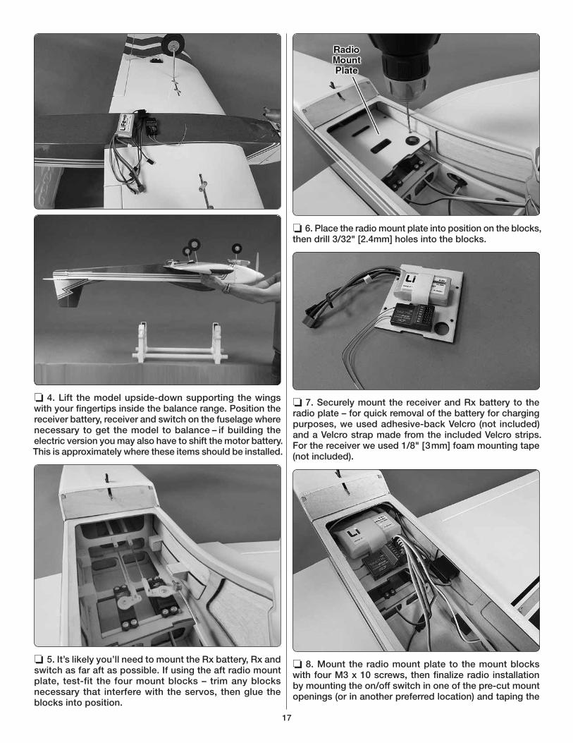
❏ 4. Lift the model upside-down supporting the wings with your fingertips inside the balance range. Position the receiver battery, receiver and switch on the fuselage where necessary to get the model to balance – if building the electric version you may also have to shift the motor battery. This is approximately where these items should be installed.
❏ 5. It’s likely you’ll need to mount the Rx battery, Rx and switch as far aft as possible. If using the aft radio mount plate, test-fit the four mount blocks – trim any blocks necessary that interfere with the servos, then glue the blocks into position.
❏ 6. Place the radio mount plate into position on the blocks, then drill 3/32" [2.4mm] holes into the blocks.
❏ 7. Securely mount the receiver and Rx battery to the radio plate – for quick removal of the battery for charging purposes, we used adhesive-back Velcro (not included) and a Velcro strap made from the included Velcro strips. For the receiver we used 1/8" [3mm] foam mounting tape (not included).
❏ 8. Mount the radio mount plate to the mount blocks with four M3 x 10 screws, then finalize radio installation by mounting the on/off switch in one of the pre-cut mount openings (or in another preferred location) and taping the

18
receiver antennas to the inside of the fuselage orientated per the manufacturer’s instructions. Note: If you're connecting the aileron servos to separate channels in the receiver, connect a 6" [150 mm] servo extension into each aileron channel in the receiver. If you're running the aileron servos from the same channel, connect a Y-connector to the aileron channel in the receiver.
Prepare the Model for Flight
❏ 1. Now that the radio is mounted, double-check the C.G. to make sure the model balances within the specified range – the model should be completely ready to fly with all components installed (and an empty fuel tank if using a glow engine). If necessary, relocate the battery or other components to get the model to balance, or use stick-on lead weight.
❏ 2. Check and set the control throws according to the measurements below:
Note: The throws are measured at the widest part of the rudder and elevator.
These are the recommended control surface throws:
ELEVATOR
LOW RATE
RUDDER
AILERONS
HIGH RATE
7/16"[ 11mm]
9°
Up
1"[ 25mm]
13°
Right
3/8"[10 mm]
16°
Up
5/8"[16mm]
13°
Up
1-3/4"[ 44mm]
23°
Right
5/8"[16mm]
25°
Up
7/16"[ 11mm]
9°
Down
1"[ 25mm]
13°
Left
3/8"[10 mm]
16°
Down
5/8"[16mm]
13°
Down
1-3/4"[ 44mm]
23°
Left
5/8"[16mm]
25°
Down
Balance the Model Laterally
❏ 1. Lift the Kaos several times by the propeller shaft and the tail to see if one wing drops.
❏ 2. If one wing drops consistently, add weight to the opposite tip by sticking it to the outside or strategically concealing it inside the balsa tip. An airplane that has been laterally balanced will track better in flight and maintain its heading better during maneuvers when the plane is climbing.
PREFLIGHT
ENGINE SAFETY PRECAUTIONS
Failure to follow these safety precautions may result in
severe injury to yourself and others.
● Keep all engine fuel in a safe place, away from high heat, sparks or flames, as fuel is very flammable. Do not smoke near the engine or fuel; and remember that engine exhaust gives off a great deal of deadly carbon monoxide. Therefore do not run the engine in a closed room or garage.
● Get help from an experienced pilot when learning to operate engines.
● Use safety glasses when starting or running engines.
● Do not run the engine in an area of loose gravel or sand; the propeller may throw such material in your face or eyes.
● Keep your face and body as well as all spectators away from the plane of rotation of the propeller as you start and run the engine.
● Keep these items away from the prop: loose clothing, shirt sleeves, ties, scarfs, long hair or loose objects such as pencils or screwdrivers that may fall out of shirt or jacket pockets into the prop.
● Use a “chicken stick” or electric starter to start the engine. Do not use your fingers to flip the propeller. Make certain the glow plug clip or connector is secure so that it will not pop off or otherwise get into the running propeller.
● Make all engine adjustments from behind the rotating propeller.
● The engine gets hot! Do not touch it during or right after operation. Make sure fuel lines are in good condition so fuel will not leak onto a hot engine, causing a fire.
● To stop a glow engine, cut off the fuel supply by closing off the fuel line or following the engine manufacturer’s recommendations. Do not use hands, fingers or any other body part to try to stop the engine. To stop a gasoline powered engine an on/off switch should be connected to the engine coil. Do not throw anything into the propeller of a running engine.

19
ELECTRIC MOTOR SAFETY
PRECAUTIONS
● The motor gets HOT! Do not touch it during or right after operation.
● When working on your plane, remove the propeller if the motor batteries will be connected.
● Always remove the motor batteries when charging.
● Follow the charging instructions included with your charger for charging LiPo batteries. LiPo batteries can cause serious damage if misused.
● Once the motor batteries are connected the electric motor can start at any time. Make sure the fail safe is set on your radio to prevent the motor from starting if the signal is lost.
● ALWAYS unplug the motor batteries fi rst.
● NEVER switch off the transmitter with the motor batteries plugged in.
● WARNING: Read the entire instruction sheet included with your motor batteries. Failure to follow the instructions could cause permanent damage to the battery and its surroundings and cause bodily harm!
● ONLY use a LiPo approved charger.
● NEVER use a NiCd/NiMH peak charger to charge a LiPo battery.
● NEVER charge in excess of 4.20V per cell.
● ONLY charge through the “charge” lead.
● NEVER charge through the “discharge” lead.
● NEVER charge at currents greater than 1C unless the battery is rated for a higher charge rate.
● ALWAYS set the charger’s output volts to match the battery volts.
● ALWAYS charge a LiPo battery in a fi reproof location.
● NEVER trickle charge a LiPo battery.
● NEVER allow the battery temperature to exceed 150° F (65° C).
● NEVER disassemble or modify the pack wiring in any way or puncture the cells.
● NEVER discharge below 2.7V per cell.
● NEVER place the battery or charger on combustible materials or leave it unattended during charge or discharge.
● ALWAYS KEEP OUT OF THE REACH OF CHILDREN.
● NEVER charge the battery in the plane.
● ALWAYS remove the battery from the plane after a crash. Set it aside in a safe location for at least 20 minutes. If the battery is damaged in the crash it could catch fi re.
● If the battery starts to swell, quickly move the battery to a safe location, preferably outside. Place it in a bucket, covering the battery with sand. Never use water to try and put out a LiPo fi re.
WARNING: For brushless electric motors, never have the
motor battery connected to the ESC without the transmitter
turned on – after each fl ight (or any time after running the
motor), always disconnect the battery before turning off
the transmitter. And when ready to fl y (or whenever running
the motor for any reason), always turn on the transmitter
fi rst before connecting the motor battery.
Also make certain your failsafe is programmed correctly
so in the event the receiver ever loses signal (or, if you
inadvertently turn off the transmitter before disconnecting
the battery or vice-versa) the motor will not turn. Follow
the instructions that came with your radio control system
to check and set the failsafe.
The recommended RimFire .80 is rated for 52A constant current and 65A surge current. Powered by a 6S LiPo on an APC 14 x 10E it draws about 55A static and momentary, maximum peaks of about 53A in the air, but averages a little less than 30A through a “normal” flight. This is an absolutely safe and conservative propeller choice and flies the Kaos well – it can be zoomed around boring holes in the sky, or flown like a classic pattern plane executing graceful maneuvers with conservative throttle management. Vertical performance is unlimited or virtually unlimited. With an APC 15 x 8E the Kaos becomes a rocket, but maximum, in-flight peaks rise to 62 – 63A (right up against the maximum surge current limit). Over the course of a typical flight, average current may still be around 30A, but could be as high as 40A if flown aggressively. The 15 x 8 is still a viable propeller choice, but due to the higher current spikes during full-throttle application proper throttle management must be used so as not to overheat the motor.
With either prop, typical flight time may be as low as 4 minutes or over 8 minutes depending on how aggressive and active you are with the throttle – more power means shorter flight times.
In any case, use a flight timer initially set to a conservative time (4 minutes for example). When the timer sounds, land. Resting (unloaded) voltage should not be below 3.75V/cell. When you charge the battery note how much capacity it took to recharge (indicating how much was used for the flight). Strive to use no more than 80% of the battery’s capacity. Adjust your timer according to the voltage and capacity used for the flight.
CAUTION: Never run the motor on the ground for more
than a few seconds. Otherwise, you may overload the
motor, battery or ESC.
NOTE: The recommended servos consume approximately 5 mAh per minute during an average flight. For a typical 7-minute flight that would be approximately 35mAh per flight. With the recommended 2S 1100 mAh LiFe battery, you should be able to get over 10 flights between charges and still use less than half the battery capacity. Keep your own notes and records to find out how many flights you can get between charges.

20
Battery Precautions
Before mounting the motor and setting up the ESC and battery, read the following important battery precautions:
IMPORTANT: If using multiple battery packs that are connected with an adapter, never charge the batteries together through the adapter. Always charge each battery pack separately. Charge the batteries, then read the following precautions on how to connect multiple packs for fl ying the model:
Battery Precautions:
There are two ways to connect multiple battery packs: In Series and in Parallel.
This is a SERIES battery adapterthat connects two batteries in series.
(3-Cell) 3200 mAh
(2-Cell) 3200 mAh
11.1V
7.4V
These are two 3200mAh batteries (one 11.1V and the other 7.4V). When joined in SERIES, the result will be a 18.5V, 3200 mAh battery.
1. Connecting batteries in “Series” means to connect the +’s to the –’s and the –’s to the +’s. This combines the battery’s Voltages, but the capacity remains the same.
This is a PARALLEL battery adapter thatconnects two batteries in parallel.
(3-Cell) 1500 mAh
(3-Cell) 1500 mAh11.1V
11.1V
These two 1500mAh batteries (both 11.1V) are being joined in PARALLEL. The result will be one 11.1V, 3000mAh battery.
2. Connecting batteries in “Parallel” means to connect the +’s to the +’s and the -’s to the -’s. This combines the battery’s capacities, but the Voltage remains the same.
PARALLELadapter
(2-Cell)
(3-Cell)11.1V
7.4V
PARALLELter
(3
NEVER connect battery packs with different Voltages in Parallel–only combine in Series. Otherwise, the batteries will try to “equalize” with the larger one trying to “charge” the smaller one, thus causing heat and likely a fi re.
(3-Cell) 3200mAh11.1V
(3-Cell) 1250mAh11.1V
SERIESadapter
h
SERIESter
Also NEVER connect battery packs with different ca-pacities in Series or in Parallel.
Range Check
Don’t forget to perform your usual ground range checks as written in the instruction manual that came with your radio system to be certain it is operating correctly.
AMA SAFETY CODE
Read and abide by the following excerpts from the Academy of Model Aeronautics Safety Code. For the complete Safety Code refer to Model Aviation magazine, the AMA web site or the Code that came with your AMA license.
General
1) I will not fly my model aircraft in sanctioned events, air shows, or model flying demonstrations until it has been proven to be airworthy by having been previously, successfully flight tested.

21
2) I will not fly my model aircraft higher than approximately 400 feet within 3 miles of an airport without notifying the airport operator. I will give right-of-way and avoid flying in the proximity of full-scale aircraft. Where necessary, an observer shall be utilized to supervise flying to avoid having models fly in the proximity of full-scale aircraft.
3) Where established, I will abide by the safety rules for the flying site I use, and I will not willfully and deliberately fly my models in a careless, reckless and/or dangerous manner.
5) I will not fly my model unless it is identified with my name and address or AMA number, on or in the model. Note: This does not apply to models while being flown indoors.
7) I will not operate models with pyrotechnics (any device that explodes, burns, or propels a projectile of any kind).
Radio Control
1) I will have completed a successful radio equipment ground check before the first flight of a new or repaired model.
2) I will not fly my model aircraft in the presence of spectators until I become a qualified flier, unless assisted by an experienced helper.
3) At all flying sites a straight or curved line(s) must be established in front of which all flying takes place with the other side for spectators. Only personnel involved with flying the aircraft are allowed at or in the front of the flight line. Intentional flying behind the flight line is prohibited.
4) I will operate my model using only radio control frequencies currently allowed by the Federal Communications Commission.
5) I will not knowingly operate my model within three miles of any pre-existing flying site except in accordance with the frequency sharing agreement listed [in the complete AMA Safety Code].
9) Under no circumstances may a pilot or other person touch a powered model in flight; nor should any part of the model other than the landing gear, intentionally touch the ground, except while landing.
Cow
l tem
plat
e fo
r O.S
. Max
.65
AX
6-1/16" [155 mm]
22
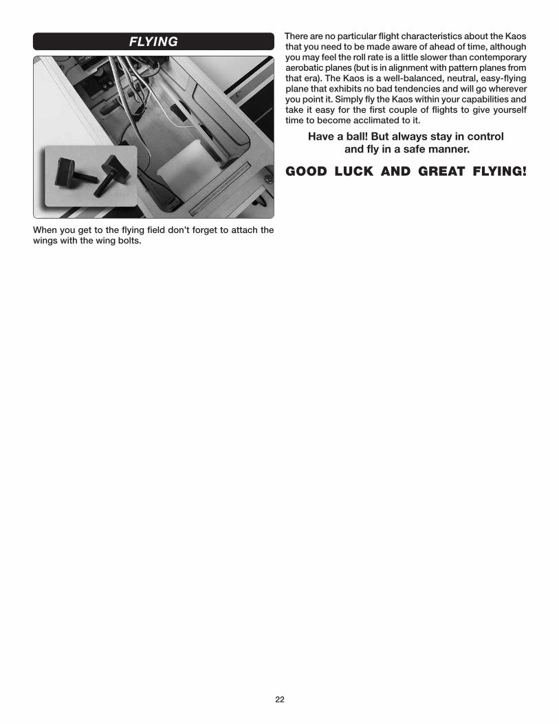
FLYING
When you get to the flying field don’t forget to attach the wings with the wing bolts.
There are no particular flight characteristics about the Kaos that you need to be made aware of ahead of time, although you may feel the roll rate is a little slower than contemporary aerobatic planes (but is in alignment with pattern planes from that era). The Kaos is a well-balanced, neutral, easy-flying plane that exhibits no bad tendencies and will go wherever you point it. Simply fly the Kaos within your capabilities and take it easy for the first couple of flights to give yourself time to become acclimated to it.
Have a ball! But always stay in controland fly in a safe manner.
GOOD LUCK AND GREAT FLYING!

23
NOTES

TOWA2058© 2015 Tower Hobbies.® A subsidiary of Hobbico, Inc.