instruction manual models 1653a & 1655a - cede · instruction manual for models 1653a &...
TRANSCRIPT

Isolated-Variable AC POWER SUPPLY
Aislada, variable FUENTE DE PODER DE AC
INSTRUCTION MANUAL
MANUAL DE INSTRUCCIÓN
MODELS 1653A & 1655A MODELOS 1653A & 1655A

TEST INSTRUMENT SAFETY
WARNING An electrical shock causing 10 milliamps of current to pass through the heart will stop most human heartbeats. Voltage as low as 35 volts dc or ac rms should be considered dangerous and hazardous since it can produce a lethal current under certain conditions. Higher voltages are even more dangerous. Your normal work habits should include all accepted practices to prevent contact with exposed high voltage, and that will steer current away from your heart in case of accidental contact with a high voltage. You will significantly reduce the risk factor if you know and observe the following safety precautions:
1. The B+K Precision Models 1655A and 1653A AC Power Supplies are sources of high voltage ac. The person using the instrument should be a qualified electronics technician or otherwise trained and qualified to work with high voltage.
2. Use only a polarized 3-wire ac outlet. This assures that the power supply chassis, case, and ground terminal are connected to a good earth ground and reduces danger from electrical shock.
3. When servicing any equipment equipped with a two-wire ac plug, treat it as “hot chassis” type and connect it to the ISOLATED OUTPUT outlet of the ac power supply. Even some equipment with a polarized plug is the “hot chassis” type.
4. Never connect two pieces of “hot chassis” equipment to ISOLATED OUTPUT outlets simultaneously. There may be a serious shock hazard between two chassis.
5. Don’t expose high voltage needlessly. Remove housings and covers only when necessary. Turn off equipment while making test connections in high-voltage circuits. Discharge high-voltage capacitors after removing power.
6. If possible, familiarize yourself with the equipment being tested and the location of its high voltage points. However, remember that high voltage may appear at unexpected points in defective equipment.
7. Use an insulated floor material or a large, insulated floor mat to stand on, and an insulated work surface on which to place equipment; and make certain such surfaces are not damp or wet.
8. Use the time proven “one hand in the pocket” technique while handling an instrument probe. Be particularly careful to avoid contacting a nearby metal object that could provide a good ground return path.
9. When testing ac powered equipment, remember that ac line voltage is usually present on some power input circuits such as the on-off switch, fuses, power transformer, etc. any time the equipment is connected to an ac outlet, even if the equipment is turned off.
10. Never work alone. Someone should be nearby to render aid if necessary. Training in CPR (cardio-pulmonary resuscitation) first aid is highly recommended.

Instruction Manual for
MODELS 1653A & 1655A Isolated, Variable
AC POWER SUPPLY
22820 Savi Ranch Parkway Yorba Linda, CA 92887 www.bkprecision.com
2
page
TEST INSTRUMENT SAFETY..................... inside front cover
FEATURES................................................................................ 3
SPECIFICATIONS .................................................................... 4
CONTROLS AND INDICATORS ............................................ 6
OPERATING INSTRUCTIONS.............................................. 12
Precautions ............................................................................... 13
Troubleshooting: Using the AC Power Supply as an Isolation Transformer ....................................................... 16
Troubleshooting: Using the AC Power Supply as a Variable AC Voltage Source. ...................................... ….21
Troubleshooting: Using the AC Power Supply to Measure Electrical Loads.................................................. 23
Using the Model 1655A as a Leakage Tester ........................... 25
Soldering Iron Temperature Control......................................... 27
page
CIRCUIT DESCRIPTION..........................................................29
MAINTENANCE AND CALIBRATION..................................30
Preventive Maintenance...............................................................30
Returning for Service...................................................................30
Fuse Replacement........................................................................30
Auto-Transformer Brush Replacement........................................31
Calibration Adjustments..............................................................31
Performance Tests........................................................................34
Troubleshooting...........................................................................35
CUSTOMER SUPPORT.............................................................37
WARRANTY INFORMATION.................................................38
Warranty Service Instructions......................................................38
Spanish Manual............................................................................39
TABLE OF CONTENTS

3
Built-in solid state soldering iron temperature control.
FEATURES
Unless otherwise stated, all information in this section applies equally to Model 1653A and 4655A
WIDE VOLTAGE RANGE Output voltage continuously variable from 0 to 150VAC.
WIDE CURRENT RANGE Model 1655A
Heavy duty unit handles virtually all servicing needs. Output current up to 3 amps continuous, 4 amps intermittent.
Model 1653A Handles many servicing needs. Output current up to 2 amps continuous.
WIDE LOAD MEASUREMENT CAPABILITY Model 1655A
Built in multi-function meter. 0-150V. Two current ranges of 0-2A and 0-4A for improved resolution. Current scales also calibrated in VA at 120V.
Model 1653A Built in dual-purpose meter measures output voltage from 0-150V and output current from 0-2A.
ISOLATED OUTPUT VOLTAGE Built-in isolation transformer for safe servicing of “hot chassis” equipment. One isolated outlet on Mode 1653A, two isolated outlets on Model 1655A for greater convenience.
BUILT-IN METER
Model 1655A
3-1/4 inch meter. Multi-color scales. Overrange
protection
Model 1653A
2 inch meter. Overrange protection.
---Model 1655A offers the following additional features--
-
POWER LINE LEAKAGE TEST
OSHA, UL, and CSA power line leakage test capability; fast and safe measurement.
EXPANDED LEAKAGE SCALE
0-5mA (0-5000µA) leakage scale is expanded in most commonly used 100-500µA portion, compressed to 5 mA
full scale. Overload protected.
CIRCUIT BREAKER OVERLOAD PROTECTION
Isolated output protected by easily reset circuit breaker.
SOLDERING IRON TEMPERATURE CONTROL
Built-in solid state soldering iron temperature control
4
SPECIFICATIONS
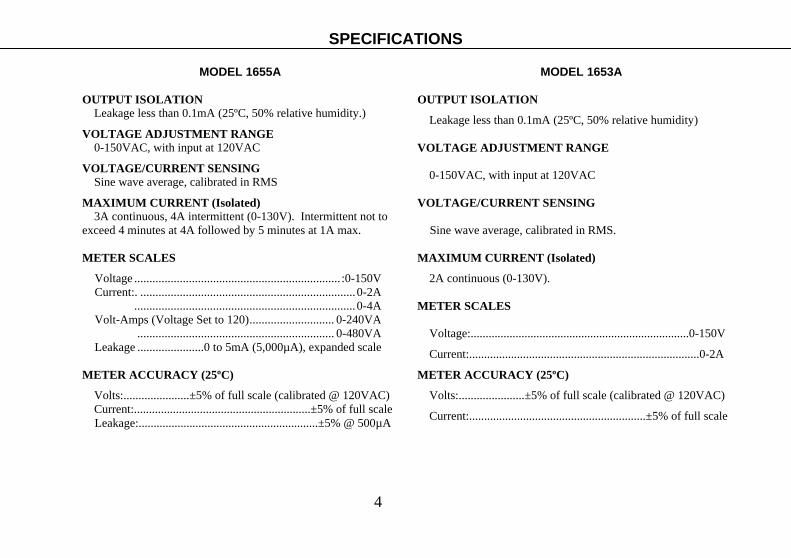
MODEL 1655A
OUTPUT ISOLATION Leakage less than 0.1mA (25ºC, 50% relative humidity.)
VOLTAGE ADJUSTMENT RANGE 0-150VAC, with input at 120VAC
VOLTAGE/CURRENT SENSING Sine wave average, calibrated in RMS
MAXIMUM CURRENT (Isolated) 3A continuous, 4A intermittent (0-130V). Intermittent not to
exceed 4 minutes at 4A followed by 5 minutes at 1A max.
METER SCALES
Voltage .................................................................... :0-150V Current:. .......................................................................0-2A .........................................................................0-4A Volt-Amps (Voltage Set to 120)............................ 0-240VA ................................................................. 0-480VA Leakage ......................0 to 5mA (5,000µA), expanded scale
METER ACCURACY (25ºC)
Volts:......................±5% of full scale (calibrated @ 120VAC) Current:...........................................................±5% of full scale
Leakage:............................................................±5% @ 500µA
MODEL 1653A
OUTPUT ISOLATION
Leakage less than 0.1mA (25ºC, 50% relative humidity)
VOLTAGE ADJUSTMENT RANGE
0-150VAC, with input at 120VAC
VOLTAGE/CURRENT SENSING
Sine wave average, calibrated in RMS.
MAXIMUM CURRENT (Isolated)
2A continuous (0-130V).
METER SCALES
Voltage:.........................................................................0-150V
Current:.............................................................................0-2A
METER ACCURACY (25ºC)
Volts:......................±5% of full scale (calibrated @ 120VAC)
Current:...........................................................±5% of full scale

5
MODEL 1655A
INPUT POWER
120 VAC 10%, 60Hz, 600VA.
OPERATING TEMPERATURE RANGE 0° C to +40°C.
STORAGE TEMPERATURE -30° C to +60°C.
WEIGHT 22lb (10kg.)
DIMENSIONS (WxHxD) 10.5” x 5.7” x 12” (267 x 145 x 305 mm)
PEAK CURRENT (Inrush) 30 A max (inrush limited to one cycle at 30A).
SOLDER IRON TEMPERATURE CONTROL 70% - 99% of power line (100W max).
MODEL 1653A
INPUT POWER
120 VAC ±10%, 60Hz, 300 VA.
OPERATING TEMPERATURE RANGE
0°C to +40°C.
STORAGE TEMPERATURE
-30°C TO +60°C.
WEIGHT
12 lb (5.5 kg).
DIMENSIONS (WxHxD)
5.5” x 6.5” x 10.5” (140 x 165 x 267 mm).
NOTE: Specifications and information are subject to change without notice. Please visit www.bkprecision.com for the most current product information.
SPECIFICATIONS
6
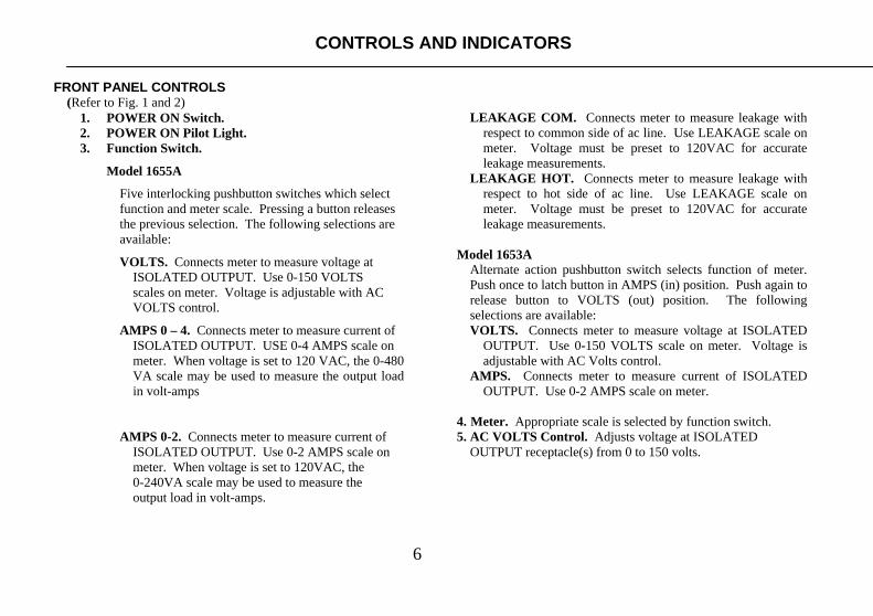
FRONT PANEL CONTROLS (Refer to Fig. 1 and 2)
1. POWER ON Switch. 2. POWER ON Pilot Light. 3. Function Switch.
Model 1655A
Five interlocking pushbutton switches which select function and meter scale. Pressing a button releases the previous selection. The following selections are available:
VOLTS. Connects meter to measure voltage at ISOLATED OUTPUT. Use 0-150 VOLTS scales on meter. Voltage is adjustable with AC VOLTS control.
AMPS 0 – 4. Connects meter to measure current of ISOLATED OUTPUT. USE 0-4 AMPS scale on meter. When voltage is set to 120 VAC, the 0-480 VA scale may be used to measure the output load in volt-amps
AMPS 0-2. Connects meter to measure current of
ISOLATED OUTPUT. Use 0-2 AMPS scale on meter. When voltage is set to 120VAC, the 0-240VA scale may be used to measure the output load in volt-amps.
LEAKAGE COM. Connects meter to measure leakage with
respect to common side of ac line. Use LEAKAGE scale on meter. Voltage must be preset to 120VAC for accurate leakage measurements.
LEAKAGE HOT. Connects meter to measure leakage with respect to hot side of ac line. Use LEAKAGE scale on meter. Voltage must be preset to 120VAC for accurate leakage measurements.
Model 1653A
Alternate action pushbutton switch selects function of meter. Push once to latch button in AMPS (in) position. Push again to release button to VOLTS (out) position. The following selections are available: VOLTS. Connects meter to measure voltage at ISOLATED
OUTPUT. Use 0-150 VOLTS scale on meter. Voltage is adjustable with AC Volts control.
AMPS. Connects meter to measure current of ISOLATED OUTPUT. Use 0-2 AMPS scale on meter.
4. Meter. Appropriate scale is selected by function switch. 5. AC VOLTS Control. Adjusts voltage at ISOLATED
OUTPUT receptacle(s) from 0 to 150 volts.
CONTROLS AND INDICATORS

7
6. ISOLATED OUTPUT Receptacle(s). Isolated, variable ac voltage outlet(s). The equipment under test plugs in here. Single outlet on Model 1653A. Dual outlets on Model 1655A.
7. *Leakage Probe. With LEAKAGE function selected,
touching probe tip to exposed metallic parts of equipment under test checks power line leakage.
8. *SOLDER TEMP Control. Full counterclockwise
rotation turns off soldering iron outlet on rear panel. Initial clockwise rotation turns on outlet at standby (warm) temperature. Further clockwise rotation increases soldering iron temperature. Temperature adjustment is tapered, allowing fine adjustment of “hot” temperature at upper end of adjustment range. This control is completely independent of the POWER ON switch.
9. *Solder Temp Pilot Light. Lights whenever soldering
iron outlet on rear panel is powered. REAR PANEL CONTROLS
(Refer to Fig. 3 and 4)
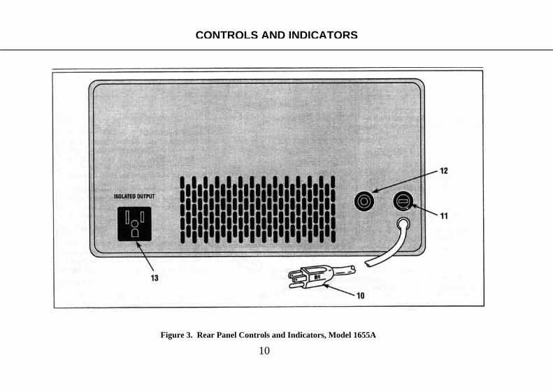
10. AC Power Cord. *=Model 1655A Only.
11. Fuse.
Model 1655A 4A fuse protects auto-transformer against excessive output current at low voltages which may not trip the input circuit breaker.
Model 1653A 3A line fuse protects against excessive input current. An internal 3A fuse protects against excessive output current at low voltages which may not blow the input fuse.
12. *Circuit Breaker. 3.15A circuit breaker protects against
excessive input current. Remove overload and push to reset.
13. *Soldering Iron Outlet. AC outlet for soldering iron. Duty
cycle, and thus temperature, is variable with SOLDER TEMP control on front panel. This outlet is intended only for non-transformer type soldering irons rated at 100 watts or less.
*=Model 1655A Only
CONTROLS AND INDICATORS

8
CONTROLS AND INDICATORS
Figure 1. Front Panel Controls and Indicators, Model 1655A

9
CONTROLS AND INDICATORS
Figure 2. Front Panel Controls and Indicators, Model 1653A
10
Figure 3. Rear Panel Controls and Indicators, Model 1655A
CONTROLS AND INDICATORS

11
Figure 4. Rear Panel Controls and Indicators, Model 1653A
CONTROLS AND INDICATORS
12
SAFETY
The Model 1655A and 1653A AC Power Supplies are sources of high voltage ac. Improper or careless use could result in fatal electrical shock. The most commonly encountered conditions which may pose a shock hazard are identified and corresponding precautions listed in the TEST INSTRUMENT SAFETY section which starts on the side front cover of this manual. Know and observe these precautions.
Although Model 1655A is equipped with dual isolated outlets,
only one “hot Chassis” equipment should be connected at a time. Unless the line-to-chassis relationship is identical, a shock hazard will exist between the two chassis.
INPUT POWER
These instruments are intended for use only with 120 volt, 60Hz line voltage. Do not operate from 50Hz, or 220-240 volt power systems. The instrument may be safely operated from 100 volt, 60Hz line voltage, although the maximum output voltage will be lower.
VENTILATION
The holes in the case provide convection cooling (hot air rises and escapes through the top vents, while cool air is drawn in to replace it through the bottom). Never block these ventilation holes with a manual, schematic diagram, other equipment, etc. If the air is blocked, the temperature inside the ac power supply may
become excessive and cause failure of the unit. Similarly, avoid operating locations near sources of heat.
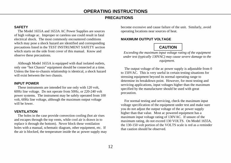
MAXIMUM OUTPUT VOLTAGE
Exceeding the maximum input voltage rating of the equipment under test (typically 130VAC) may cause severe damage to the
equipment.
The output voltage of the ac power supply is adjustable from 0 to 150VAC. This is very useful in certain testing situations for stressing equipment beyond its normal operating range to determine its breakdown point. However, for most testing and servicing applications, input voltages higher than the maximum specified by the manufacturer should be used with great precaution.
For normal testing and servicing, check the maximum input
voltage specification of the equipment under test and make sure you do not adjust the output voltage of the ac power supply higher than that value. Most ac powered equipment has a maximum input voltage rating of 130VAC. If unsure of the maximum rating, do not exceed 130 VOLTS. On Model 1655A, the 130-150 volt portion of the VOLTS scale is red as a reminder that caution should be observed.
OPERATING INSTRUCTIONS PRECAUTIONS
CAUTION
13
OPERATING INSTRUCTIONS PRECAUTIONS
Figure 5. Observe Caution Above 130V.
14
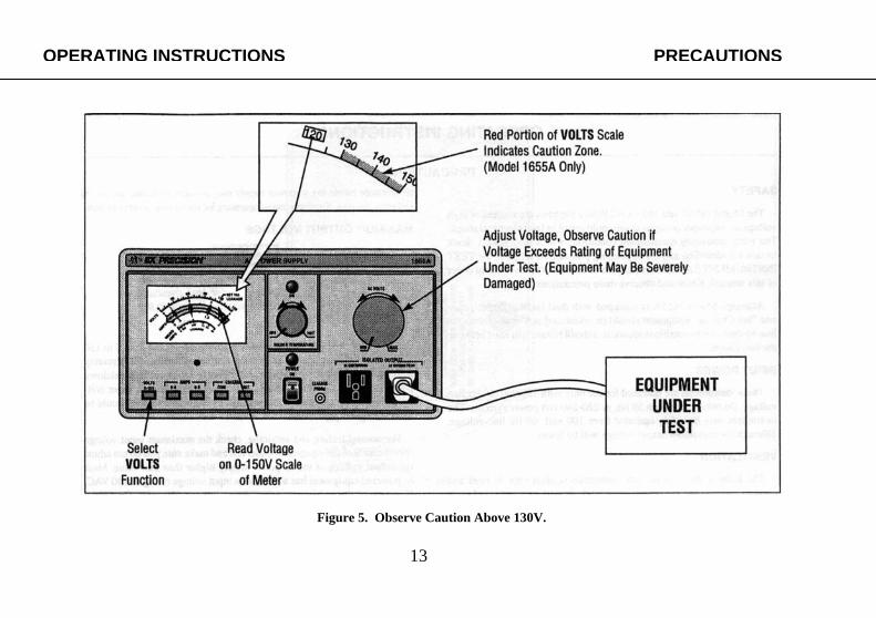
MAXIMUM OUTPUT CURRENT
NEVER EXCEED THE MAXIMUM OUTPUT CURRENT RATING OF THE UNIT (Table 1). Excessive output current
can damage the variable auto-transformer. Keep output current as low as possible; power only one piece
of equipment at a time. Use the ISOLATED OUTPUT only for the equipment under test – not for the test equipment.
It is very important to observe the maximum current derating (Table 1) above 130 volts, and to allow sufficient cooling time when operating Model 1655A in the intermittent duty region.
Even at low voltages, the maximum output current should never exceed 4 amps for Model 1655A or 2 amps for Model 1653A. Higher current may damage the variable auto-transformer where the brush contacts the winding. A 3.15A circuit breaker limits maximum input current to Model 1655A, while a 3A fuse is used for Model 1653A. Additionally, output fuses limit the output of the 1655A to 4 amps and the 1653A to 3 amps at low voltages that would not open the input protective device. Never bypass the circuit breaker or fuses, or replace fuses with a higher value.
Remove the overload to reset the circuit breaker or replace a fuse. Turn off the unit when connecting or disconnecting equipment from the ISOLATED OUTPUT receptacle(s).
For Model 1655A, the red portion of the 0-4A scale of the meter indicates the caution zone (over 3A). This is a reminder that only intermittent duty operation is permitted.
For Model 1635A, the output current should not exceed 2 amps
for continuous duty or intermittent duty operation. The full scale meter indication of 2A is a reminder that this is the maximum permissible output current.
CAUTION
Precautions OPERATING INSTRUCTIONS
Table 1. Maximum Output Current Derating.

15
OPERATING INSTRUCTIONS PRECAUTIONS
Figure 6. Maximum Current Considerations.

16
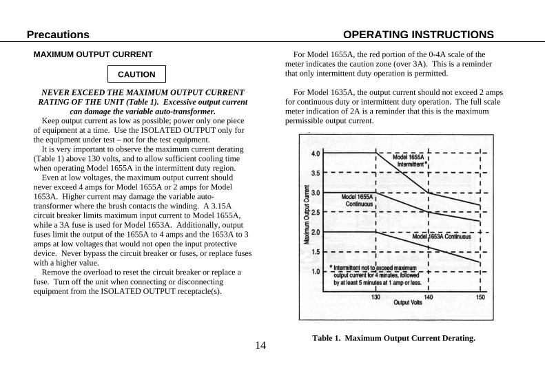
THE HAZARD Most equipment with a 2-Wire Plug is Transformerless
Most recent television receivers and other consumer products such as stereo amplifiers, tuners, tape decks, etc. do not contain an isolation transformer. Such products often have a plastic or wood cabinet which completely insulates the chassis and prevents the user from touching it. However, when the cabinet is removed for servicing the product, the chassis is exposed and may become an electrical shock hazard to the service technician.
Bridge Rectifier Transformerless Equipment
One of the most commonly used types of power supply circuits in television receivers and audio equipment is the transformerless full wave bridge rectifier shown in Fig 7. In such cases, the chassis is always “hot”, regardless of which way the 2-wire ac plug is inserted. Touching a “hot” chassis is hazardous and can cause fatal electrical shock.
Just because a unit uses a polarized power plug does not guarantee safety. Some equipment with a bridge rectifier uses a
polarized power plug, and as mentioned above, always has a “hot” chassis.
Transformerless Half-Wave Rectifier Equipment Another commonly used transformerless power supply circuit
is a half-wave rectifier where one side of the ac power line connects directly to the chassis (also shown in Fig. 7). Unless the equipment is equipped with a polarized plug to prevent insertion the “wrong” way, the chassis may be “hot” (120VAC with respect to earth ground) and cause an electrical shock if touched.
Other Transformerless Hazards
Equipment with voltage doubler power supplies may also be of the “hot Chassis” variety and pose the same safety hazard. In fact, and equipment with a 2-wire ac power plug should be treated as hazardous “hot” chassis type and the safety precautions listed on the next page should be taken.
Test Equipment Damage Hazard
In addition, to the electrical shock hazard if the “hot” chassis is touched, there is also a high probability of damaging any ac-powered test equipment used to service the equipment. Most test equipment with a 3-wire power cord, such as oscilloscopes and signal generators, have an earth ground chassis (connected to earth ground through the third wire of the ac power plug). Touching the ground lead of any such test equipment probe to a “hot” chassis shorts the hot side of the power line through the ground lead and instrument. Since the path through the instrument is intended only as a signal ground, the excessive current of a direct power line short may cause extensive damage to the test equipment or to the equipment under test.
Troubleshooting: Use As Isolation Transformer OPERATING INSTRUCTIONS TROUBLESHOOTING: USING THE AC POWER SUPPLY AS ISOLATION TRANSFORMER
WARNING
nt Considerations.
17
OPERATING INSTRUCTIONS Troubleshooting: Use As Isolation Transformer
Figure 7. Servicing “Hot Chassis” Equipment Can Pose a Serious Shock Hazard.
18
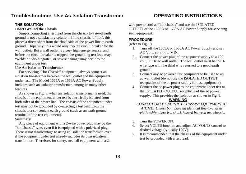
THE SOLUTION Don’t Ground the Chassis
Simply connecting a test lead from the chassis to a good earth ground is not a satisfactory solution. If the chassis is “hot”, this places a direct short from the “hot” side of the power line to earth ground. Hopefully, this would only trip the circuit breaker for the wall outlet. But a wall outlet is a very high energy source, and before the circuit breaker is tripped, the grounding test lead may “weld” or “disintegrate”, or severe damage may occur to the equipment under test. Use An Isolation Transformer For servicing “Hot Chassis” equipment, always connect an isolation transformer between the wall outlet and the equipment under test. The Model 1655A or 1653A AC Power Supply includes such an isolation transformer, among its many other features. As shown in Fig. 8, when an isolation transformer is used, the chassis of the equipment under test is electrically isolated from both sides of the power line. The chassis of the equipment under test may not be grounded by connecting a test lead from the chassis to a convenient earth ground (such as an earth ground terminal of the test equipment). Summary Any piece of equipment with a 2-wire power plug may be the “hot chassis” type, even if it is equipped with a polarized plug. There is not disadvantage to using an isolation transformer, even if the equipment under test already includes its own isolation transformer. Therefore, for safety, treat all equipment with a 2-
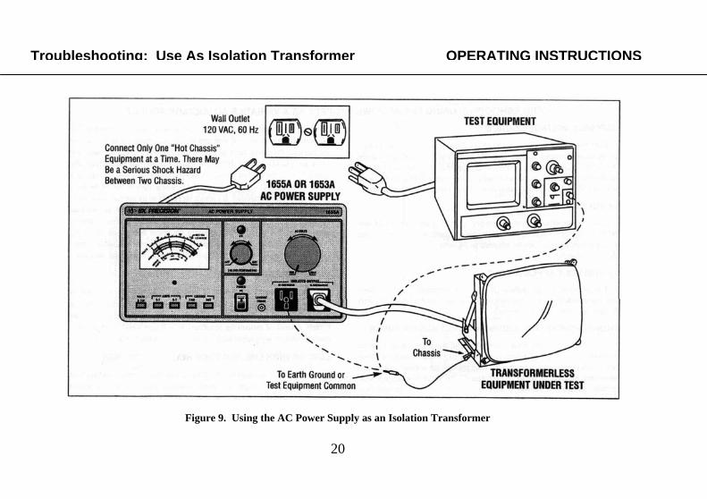
wire power cord as “hot chassis” and use the ISOLATED OUTPUT of the 1655A or 1653A AC Power Supply for servicing such equipment. PROCEDURE (refer to Fig. 9)
1. Turn off the 1655A or 1653A AC Power Supply and set AC Volts control to MIN.
2. Connect the power plug of the ac power supply to a 120 volt, 60 Hz ac wall outlet. The wall outlet must be the 3-wire type with the third wire returned to a good earth ground.
3. Connect any ac powered test equipment to be used to an ac wall outlet (do not use the ISOLATED OUTPUT receptacles of the ac power supply for test equipment).
4. Connect the ac power plug to the equipment under test to the ISOLATED OUTPUT receptacle of the ac power supply. This provides the isolation as shown in Fig. 8.
WARNING CONNECT ONLY ONE “HOT CHASSIS” EQUIPMENT AT
A TIME. Unless both have an identical line-to-chassis relationship, there is a shock hazard between two chassis.
5. Turn the POWER ON. 6. Select VOLTS function and adjust AC VOLTS control to
desired voltage (typically 120V). 7. It is recommended that the chassis of the equipment under
test be grounded with a test lead.
Troubleshooting: Use As Isolation Transformer OPERATING INSTRUCTIONS

19
OPERATING INSTRUCTIONS Troubleshooting: Use As Isolation Transformer
Figure 8. Eliminating the Hazard of Servicing Transformerless Equipment
20
Figure 9. Using the AC Power Supply as an Isolation Transformer
Troubleshooting: Use As Isolation Transformer OPERATING INSTRUCTIONS
21
VARIABLE VOLTAGE SOURCE Both the Model 1655A and 1653A AC Power Supplies offer continuously variable output voltage from 0 to 150VAC. Several applications are listed below, but the versatile instruments may be used in any application where an ac power source of any value from 0 to 150 volts is required, and within the maximum current rating of the instrument. 24 VOLT APPLICATIONS Class II industrial control equipment operates from nominal 24 volt, 60 Hz ac power. Such equipment is widely used in industrial plants. These power supplies can be adjusted to 24 volts ac for bench servicing of the equipment. 130-150 VOLT APPLICATIONS The ability to go higher then 130 volts is indispensable in component and equipment testing where specifications must be exceeded to verify designs and overvoltage margins. TROUBLESHOOTING EQUIPMENT THAT BLOWS FUSES One of the problems with troubleshooting equipment with a severe overload or short is that it repeatedly trips its circuit breaker or blows fuses. Full power cannot be applied long enough for normal voltage and waveform measurements to be performed. The variable voltage feature permits operation at a lower voltage that does not activate the protective device; testing and troubleshooting can be performed with power applied.
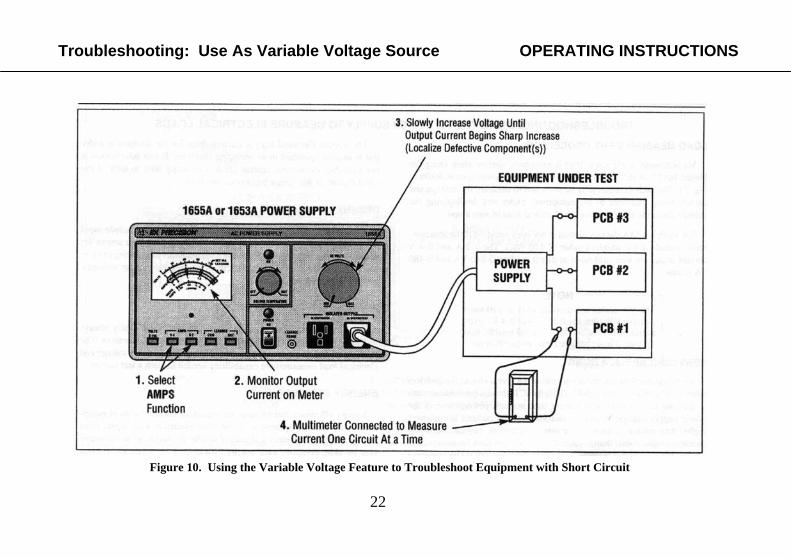
Using the Model 1655A or 1653A AC Power Supply as shown in Fig. 10, voltage can be set to 0 volt and slowly increased while monitoring the current. Problems such as a defective circuit breaker that open too soon are quickly spotted. If current reaches its normal value (typically, about 70% of the fuse of protective device rating) at a low voltage such as 20 volts, there is a major short in the power supply or one of the main power distribution circuits. If current increases to its normal value more gradually, allowing voltage to approach 100 volts or more, an overload in one of the circuits is probably the cause. Current that increases sharply above a certain voltage may indicate electrical breakdown or arcing within a component. Voltage or current measurements in various circuits (see Fig. 10) while varying the input voltage can help isolate the fault. INPUT VOLTAGE SPECIFICATION TESTING Most ac powered equipment is specified to operate over a range of input voltage such as 120VAC ±10%. Complete performance testing cannot be conducted without a variable ac source. Some testing may merely consist of measuring regulated dc voltages while varying the ac source voltage; with other tests conducted at nominal line voltage. LOW OR HIGH LINE VOLTAGE RELATED FAILURES Occasionally, an equipment malfunctions only during conditions of low or high line voltage. Troubleshooting of such problems is almost impossible without a variable ac voltage source. Either Model 1655A or 1653A AC Power Supply serves as a variable ac voltage source.
OPERATING INSTRUCTIONS Troubleshooting: Use As Variable Voltage Source TROUBLESHOOTING: USING THE AC POWER SUPPLY AS A VARIABLE AC VOLTAGE SOURCE
22
Figure 10. Using the Variable Voltage Feature to Troubleshoot Equipment with Short Circuit
Troubleshooting: Use As Variable Voltage Source OPERATING INSTRUCTIONS
23
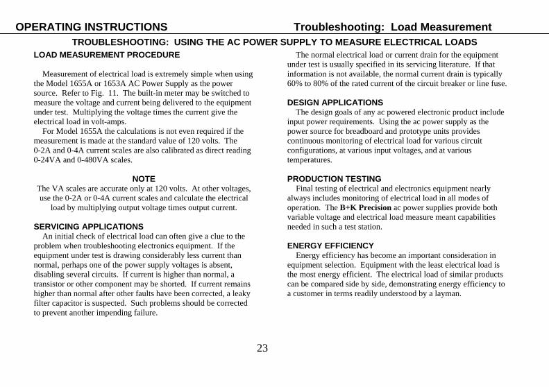
LOAD MEASUREMENT PROCEDURE Measurement of electrical load is extremely simple when using the Model 1655A or 1653A AC Power Supply as the power source. Refer to Fig. 11. The built-in meter may be switched to measure the voltage and current being delivered to the equipment under test. Multiplying the voltage times the current give the electrical load in volt-amps. For Model 1655A the calculations is not even required if the measurement is made at the standard value of 120 volts. The 0-2A and 0-4A current scales are also calibrated as direct reading 0-24VA and 0-480VA scales.
NOTE The VA scales are accurate only at 120 volts. At other voltages, use the 0-2A or 0-4A current scales and calculate the electrical
load by multiplying output voltage times output current.
SERVICING APPLICATIONS An initial check of electrical load can often give a clue to the problem when troubleshooting electronics equipment. If the equipment under test is drawing considerably less current than normal, perhaps one of the power supply voltages is absent, disabling several circuits. If current is higher than normal, a transistor or other component may be shorted. If current remains higher than normal after other faults have been corrected, a leaky filter capacitor is suspected. Such problems should be corrected to prevent another impending failure.
The normal electrical load or current drain for the equipment under test is usually specified in its servicing literature. If that information is not available, the normal current drain is typically 60% to 80% of the rated current of the circuit breaker or line fuse. DESIGN APPLICATIONS The design goals of any ac powered electronic product include input power requirements. Using the ac power supply as the power source for breadboard and prototype units provides continuous monitoring of electrical load for various circuit configurations, at various input voltages, and at various temperatures. PRODUCTION TESTING Final testing of electrical and electronics equipment nearly always includes monitoring of electrical load in all modes of operation. The B+K Precision ac power supplies provide both variable voltage and electrical load measure meant capabilities needed in such a test station. ENERGY EFFICIENCY Energy efficiency has become an important consideration in equipment selection. Equipment with the least electrical load is the most energy efficient. The electrical load of similar products can be compared side by side, demonstrating energy efficiency to a customer in terms readily understood by a layman.
OPERATING INSTRUCTIONS Troubleshooting: Load Measurement TROUBLESHOOTING: USING THE AC POWER SUPPLY TO MEASURE ELECTRICAL LOADS

24
Troubleshooting: Load Measurement OPERATING INSTRUCTIONS
Figure 11. Measuring Electrical Load
25
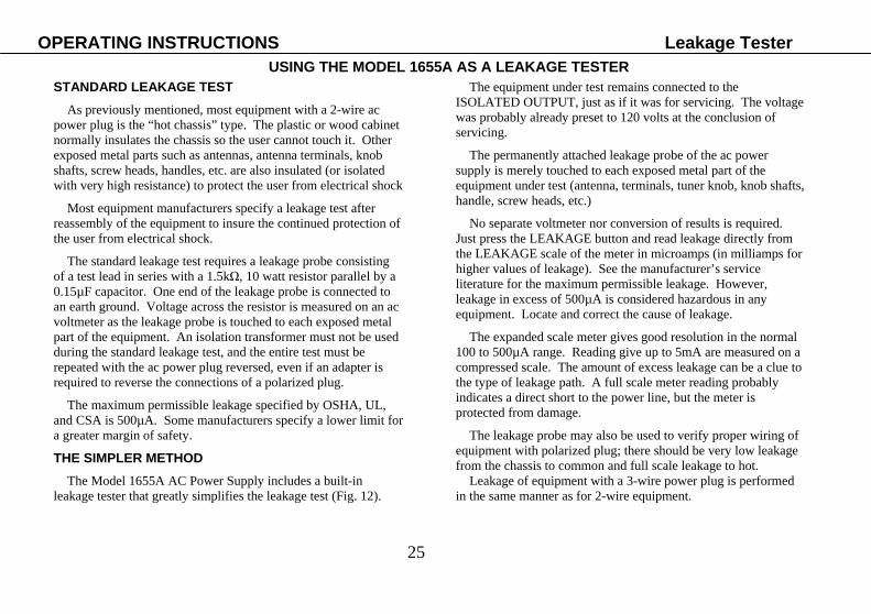
STANDARD LEAKAGE TEST As previously mentioned, most equipment with a 2-wire ac power plug is the “hot chassis” type. The plastic or wood cabinet normally insulates the chassis so the user cannot touch it. Other exposed metal parts such as antennas, antenna terminals, knob shafts, screw heads, handles, etc. are also insulated (or isolated with very high resistance) to protect the user from electrical shock Most equipment manufacturers specify a leakage test after reassembly of the equipment to insure the continued protection of the user from electrical shock. The standard leakage test requires a leakage probe consisting of a test lead in series with a 1.5kΩ, 10 watt resistor parallel by a 0.15µF capacitor. One end of the leakage probe is connected to an earth ground. Voltage across the resistor is measured on an ac voltmeter as the leakage probe is touched to each exposed metal part of the equipment. An isolation transformer must not be used during the standard leakage test, and the entire test must be repeated with the ac power plug reversed, even if an adapter is required to reverse the connections of a polarized plug. The maximum permissible leakage specified by OSHA, UL, and CSA is 500µA. Some manufacturers specify a lower limit for a greater margin of safety. THE SIMPLER METHOD The Model 1655A AC Power Supply includes a built-in leakage tester that greatly simplifies the leakage test (Fig. 12).
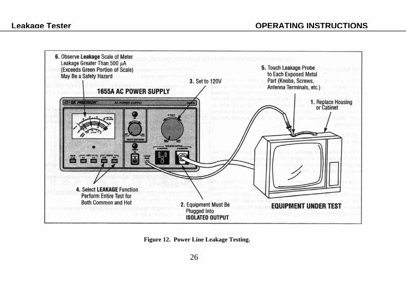
The equipment under test remains connected to the ISOLATED OUTPUT, just as if it was for servicing. The voltage was probably already preset to 120 volts at the conclusion of servicing. The permanently attached leakage probe of the ac power supply is merely touched to each exposed metal part of the equipment under test (antenna, terminals, tuner knob, knob shafts, handle, screw heads, etc.) No separate voltmeter nor conversion of results is required. Just press the LEAKAGE button and read leakage directly from the LEAKAGE scale of the meter in microamps (in milliamps for higher values of leakage). See the manufacturer’s service literature for the maximum permissible leakage. However, leakage in excess of 500µA is considered hazardous in any equipment. Locate and correct the cause of leakage. The expanded scale meter gives good resolution in the normal 100 to 500µA range. Reading give up to 5mA are measured on a compressed scale. The amount of excess leakage can be a clue to the type of leakage path. A full scale meter reading probably indicates a direct short to the power line, but the meter is protected from damage. The leakage probe may also be used to verify proper wiring of equipment with polarized plug; there should be very low leakage from the chassis to common and full scale leakage to hot. Leakage of equipment with a 3-wire power plug is performed in the same manner as for 2-wire equipment.
OPERATING INSTRUCTIONS Leakage Tester USING THE MODEL 1655A AS A LEAKAGE TESTER
26
Leakage Tester OPERATING INSTRUCTIONS
Figure 12. Power Line Leakage Testing.
27
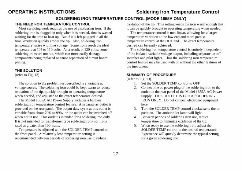
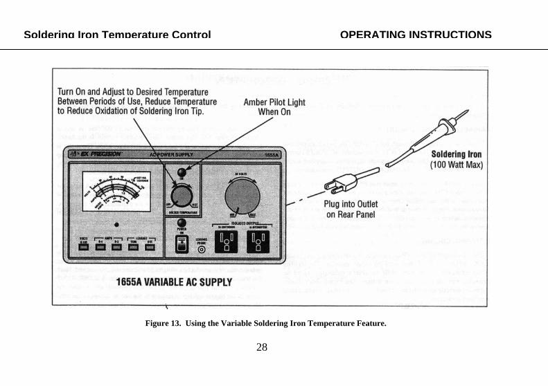
THE NEED FOR TEMPERATURE CONTROL Most servicing work requires the use of a soldering iron. If the soldering iron is plugged in only when it is needed, time is wasted waiting for the iron to heat up. But if it is left plugged in all the time, oxidation quickly erodes the tip. Also, soldering iron temperature varies with line voltage. Some irons reach the ideal temperature at 105 to 110 volts. As a result, at 120 volts, some soldering irons are too hot, which can more easily damage components being replaced or cause separation of circuit board plating. THE SOLUTION (refer to Fig. 13) The solution to the problem just described is a variable ac voltage source. The soldering iron could be kept warm to reduce oxidation of the tip, quickly brought to operating temperature when needed, and adjusted to the exact temperature desired. The Model 1655A AC Power Supply includes a built-in soldering iron temperature control feature. A separate ac outlet is provided on the rear panel. The output duty cycle at this outlet is variable from about 70% to 99%, or the outlet can be switched off when not in use. This outlet is intended for a soldering iron only. It is not intended for transformer type soldering irons nor irons rated at greater than 100 watts. Temperature is adjusted with the SOLDER TEMP control on the front panel. A relatively low temperature setting is recommended between periods of soldering iron use to reduce
oxidation of the tip. This setting keeps the iron warm enough that it can be quickly brought to operating temperature when needed. The temperature control is non-linear, allowing for a larger temperature variation at the low end and more precise temperature control at the HOT end. The exact temperature desired can be easily achieved. The soldering iron temperature control is entirely independent of the isolated variable voltage output, including separate on-off switches and pilot lights. Thus the soldering iron temperature control feature may be used with or without the other features of the instrument. SUMMARY OF PROCEDURE (refer to Fig. 13)
1. Set the SOLDER TEMP control to OFF 2. Connect the ac power plug of the soldering iron to the
outlet on the rear panel of the Model 1655A AC Power Supply. THIS OUTLET IS FOR A SOLDERING IRON ONLY. Do not connect electronic equipment here.
3. Turn the SOLDER TEMP control clockwise to the on position. The amber pilot lamp will light.
4. Between periods of soldering iron use, reduce temperature to minimize oxidation of the tip.
5. When ready to use the soldering iron, adjust the SOLDER TEMP control to the desired temperature. Experience will quickly determine the typical setting for a given soldering iron.
OPERATING INSTRUCTIONS Soldering Iron Temperature Control SOLDERING IRON TEMPERATURE CONTROL (MODE 1655A ONLY)
28
Figure 13. Using the Variable Soldering Iron Temperature Feature.
Soldering Iron Temperature Control OPERATING INSTRUCTIONS

29
Refer to the separately supplied schematic diagram while reading the following circuit descriptions. VARIABLE VOLTAGE CIRCUIT Input power is applied through the POWER ON switch to variable auto-transformer TI. The output of TI is set with the AC VOLTS control from 0 to 150 volts. The selected amount of voltage is applied across isolation transformer T2 to the ISOLATED OUTPUT receptacle(s). Model 1653A is protected by input fuse F1, while Model 1655A uses circuit breaker CB1. This limits the maximum input current. Additional protection for the auto-transformer is offered by fuse F2, which limits the maximum output current at low voltages which would not open the protective device in the input circuit. In Model 1655A, this is a 4-amp fuse on the rear panel. In Model 1653A, a 3-amp internal fuse is used. METERING CIRCUIT Since the output of the unit is ac, the meter is connected across a bridge rectifier to provide the dc necessary for meter operation. The rectifier circuit senses the average level, while the meter is calibrated to read the equivalent rms value of a sine wave voltage the back-to-back diodes connected directly across the meter limit maximum voltage and thus offer overrange protection. When the VOLTS function is selected, the voltage across the ISOLATED OUTPUT is applied to the meter circuit. The meter
is shunted by the VOLTAGE CAL trim pot which calibrates the voltage scale. A 1-ohm current sensing resistor (two series 0.5-ohm in Model 1655A) develops a voltage proportional to output current. In the AMPS function, this voltage is applied across the meter circuit. The meter is now shunted by the AMPS CAL trim pot which calibrates the 2 amp current scale. In Model 1655A, the 4 amp scale is selected by sensing the voltage developed across only one of the 0.5-ohm resistors. When the LEAKAGE function is selected (Model 1655A only) the current from the leakage probe is applied to the meter circuit. Diodes D4 and D5 are reverse biased below 500 µA for expanded scale feature. At higher leakage current, the diodes become forward biased and shunt part of the current to compress the meter scale. SOLDERING IRON TEMERATURE CONTROL CIRCUIT (Model 1655A Only) Input power is applied through triac TR1 to the soldering iron outlet on the rear panel. Breakdown diode D1 does not gate the triac into conduction until its 30 volt threshold is reached. Thus, the triac does not conduct for the entire input cycle. SOLDER TEMP control R2 forms part of an RC phase shift network which varies the phase of the trigger voltage in relation to the anode voltage of the triac. This varies the non-conduction period, which adjusts the soldering iron temperature. The circuit is automatically reset each time the ac passes through zero.
CIRCUIT DESCRIPTION

30
1. The following instructions are for use by qualified service personnel only. To avoid electrical shock, do
not perform servicing other than contained in the operating instructions unless you are qualified to do so.
2. When the unit is plugged into an ac outlet, even if the POWER ON switch is off, ac line voltage is present as some input power circuits. Observe caution any time
the case is removed from the instrument.
PREVENTIVE MAINTENANCE Do not overload the instrument. Excessive output current can damage the variable auto-transformer. Prolonged use at high current accelerates failure. Keep output current as low as possible, and never exceed the maximum rating of the unit. If possible, power only one piece of equipment at a time. Use the ISOLATED OUTPUT only for the equipment under test-not for other test equipment. It is very important to observe the maximum current derating (Table 1) above 130 volts, and to allow sufficient cooling time when operating Model 1655A at greater than 3 amps outlet. Periodic inspection of the brush on the variable contact of the auto-transformer is recommended. Badly worn or arcing brushes should be replaced. See the AUTO-TRANSFORMER BRUSH REPLACEMENT paragraph for replacement procedures.
RETURNING FOR SERVICE If you have encountered a problem with your unit and choose to return it for service, check the following before returning.
1. Is the circuit breaker reset (Model 1655A)? See FUSE REPLACEMENT paragraph below if required.
2. Are the fuses okay? See FUSE REPLACEMENT paragraph below if required.
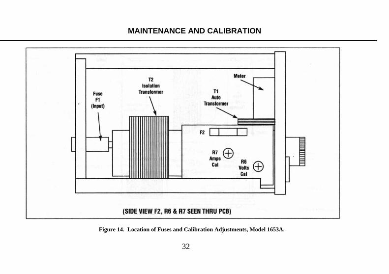
FUSE REPLACEMENT The ac power supply will trip its circuit breaker or blow a fuse only if it is severely overloaded or a failure occurs in the instrument. Always turn off the unit to reset the circuit breaker or replace a fuse. If fuses are internal, unplug the instrument from its wall outlet before attempting replacement. Before turning the unit back on, reduce the output voltage or remove the overload that caused the blown fuse. Replace the fuse only with the original type and value-never one of a large value. A larger value may create a fire and safety hazard, or cause serious damage to the equipment. Also refer to the following specific fuse replacement information for each model. Model 1653A If the instrument is severely overloaded at higher output voltages, fuse F1 on the rear panel will blow. The unit will stop operating and the pilot light will go off. If the instrument is severely overloaded at low output voltage, internal fuse F2 will blow. In this case, there will be no output but the pilot light will stay on. Fig. 14 shows the location of the fuses. Replace fuse F1 only with a 3-amp slow-blow type 3AG.
MAINTENANCE AND CALIBRATION
WARNING
31
MAINTENANCE AND CALIBRATION
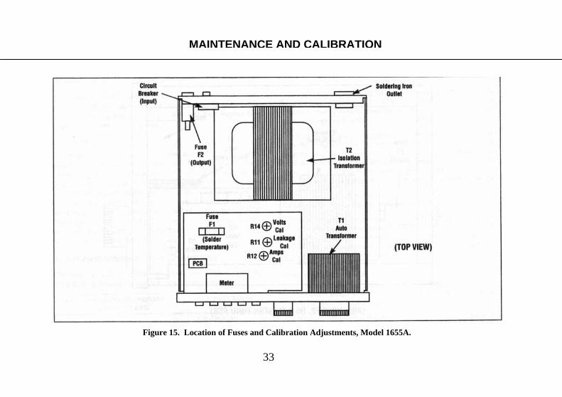
Model 1655A If this instrument is severely overloaded at higher output voltages, circuit breaker CB1 on the rear panel will trip. The unit will stop operating and the POWER ON pilot light will go off. Remove the overload and push the button on the circuit breaker to reset. A severe overload at low output voltage will blow fuse F2 on the rear panel. In this case, there will be no output but the pilot light will stay on. If the soldering iron outlet is overloaded, internal fuse F1 will blow. If so, the SOLDER TEMP pilot light will go off. Fig. 15 shows the fuse locations. Replace fuse F1 only with a 1-amp normal blow type 3AG. Replace fuse F2 only with a 4-amp slow-blow type 3AG. AUTO-TRANSFORMER BRUSH REPLACEMENT To replace the brush, unplug the instrument, then gently lift the brush from the brush track. Grasp the old brush assembly and snap it out of position by pulling radially. Install the new brush assembly by lifting the spring arm and snapping the new brush assembly into position.
It is imperative that newly installed or re-installed brushes be seated correctly on the brush track for proper operation of the transformer. With the power off, insert a piece of garnet paper (non-metallic) between the brush and brush track, rough side toward the brush. A few swing of the brush over the garnet paper will mate the brush contact face to the brush track. Remove the garnet paper and blow away loose particles before applying power.
CALIBRATION ADJUSTMENTS This unit was carefully checked and calibrated at the factory prior to shipment. Readjustment is recommended only if repairs have been made in a circuit that affects calibration, or it you have reason to believe the unit may be out of calibration. Locations of the calibration adjustments are shown in Fig. 14 (Model 1653A) and 15 (Model 1655A). Test Equipment Required
1. Multimeter, ac voltage accuracy of 0.5% or better at 120 V, 60Hz, ac current accuracy of 1% or better at 500 microamps and 2 amps, 60Hz. B+K Precision Model 2831D or equivalent.
2. 60 ohm, 240 watt resistive power supply load. Must be capable of dissipating 2 amps at 120 VAC. A variable electronic load of sufficient power rating may be used, or parallel light bulbs totaling 240 watts are suitable.
32
MAINTENANCE AND CALIBRATION
Figure 14. Location of Fuses and Calibration Adjustments, Model 1653A.
33
MAINTENANCE AND CALIBRATION
Figure 15. Location of Fuses and Calibration Adjustments, Model 1655A.

34
Meter VOLTS Calibration 1. With the power supply turned off, adjust the mechanical
zero of the meter to exact zero. 2. Connect an external multimeter of ±0.5% or better ac
voltage accuracy to the ISOLATED OUTPUT. 3. Turn on the ac power supply and set the AC VOLTS
control for 120 volts on the multimeter 4. Set function switch to VOLTS and adjust VOLTS CAL
(R6 for Model 1653A, R14 for Model 1655A) for 120 volts on built-in meter.
Meter AMPS Calibration
1. Connect a 60 ohm, 240 watt resistive load to the ISOLATED OUTPUT receptacle. Parallel light bulbs totaling 240 watts is suitable.
2. Connect a calibrated multimeter of 1% or better ac current accuracy in series with the load to measure each current. Set the multimeter to a 2-amp range.
3. Turn on the ac power supply and slowly increase the output voltage until the multimeter measures 2.0 amps.
4. Set the function switch to AMPS and adjust AMPS CAL (R7 for Model 1653A, R12 for Model 1655A) for 2.0 amps on the built-in meter.
5. For Model 1655A, adjust calibration on the 0-2A range. The adjustment calibrates both scales. If 0-4A range is inaccurate, replace R5 and R6 with matched equal resistors and repeat calibration adjustment.
Meter LEAKAGE Calibration (Model 1655A only) 1. Connect the leakage probe in series with a 220 kΩ, ¼ watt
resistor. 2. Connect a calibrated multimeter of 1% or better ac current
accuracy in series with the 220kΩ resistor and leakage probe. Set the multimeter to measure 500µA ac current.
3. Carefully connect the other lead of the multimeter to the hot side of the ISOLATED OUTPUT receptacle. Adjust the AC VOLTS control for exactly 500µA on the multimeter.
4. Select the LEAKAGE function and adjust LEAKAGE CAL (R11) for 500µA on the built-in meter.
PERFORMANCE TESTS The following checks test all functions of the ac power supply for proper operation. The sequence of the checks also provides a logical symptom and fault isolation technique for troubleshooting. After troubleshooting and repair, these tests should be performed to assure that all faults have been corrected.
1. Before the power supply is turned on, the meter should rest at exact zero. If mechanical zero adjustment is required, calibration adjustments should be rechecked.
2. Set the POWER ON switch to on. The POWER ON pilot light should illuminate.
3. Set the function switch to VOLTS and rotate the AC VOLTS control to minimum (fully counterclockwise). The output should go to zero as read on the front panel meter.
MAINTENANCE AND CALIBRATION
35
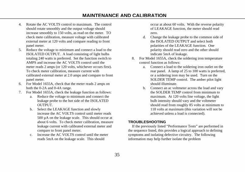
4. Rotate the AC VOLTS control to maximum. The control should rotate smoothly and the output voltage should increase smoothly to 150 volts, as read on the meter. TO check mete calibration, measure voltage with calibrated external meter at 120 volts and compare reading to front panel meter.
5. Reduce the voltage to minimum and connect a load to the ISOLATED OUTPUT. A load consisting of light bulbs totaling 240 watts is preferred. Set the function switch to AMPS and increase the AC VOLTS control until the meter reads 2 amps (or 120 volts, whichever occurs first). To check meter calibration, measure current with calibrated external meter at 2.0 amps and compare to front panel meter.
6. For Model 1655A, check that the meter reads 2 amps on both the 0-2A and 0-4A range.
7. For Model 1655A, check the leakage function as follows: a. Reduce the voltage to minimum and connect the
leakage probe to the hot side of the ISOLATED OUTPUT.
b. Select the LEAKAGE function and slowly increase the AC VOLTS control until meter reads 500 µA on the leakage scale. This should occur at about 6 volts. To check meter calibration, measure leakage current with calibrated external meter and compare to front panel meter.
c. Increase the AC VOLTS control until the meter reads 5mA on the leakage scale. This should
occur at about 60 volts. With the reverse polarity of LEAKAGE function, the meter should read zero.
d. Change the leakage probe to the common side of the ISOLATED OUTPUT and select both polarities of the LEAKAGE function. One polarity should read zero and the other should indicate 5mA of leakage.
8. For Model 1655A, check the soldering iron temperature control function as follows:
a. Connect a load to the soldering iron outlet on the rear panel. A lamp of 25 to 100 watts is preferred, or a soldering iron may be used. Turn on the SOLDER TEMP control. The amber pilot light should illuminate.
b. Connect an ac voltmeter across the load and vary the SOLDER TEMP control from minimum to maximum. At 120 volts line voltage, the light bulb intensity should vary and the voltmeter should read from roughly 85 volts at minimum to 118 volts at maximum (this variation will not be achieved unless a load is connected).
TROUBLESHOOTING If the previously listed “Performance Tests” are performed in the sequence listed, this provides a logical approach to defining symptoms and isolating defective circuitry. The following information may help further isolate the problem
MAINTENANCE AND CALIBRATION

36
No POWER ON Pilot Light This symptom indicates either a fault in the primary power circuit, or a tripped circuit breaker (Model 1655A) or blown fuse (Model 1653A). The following checks should isolate the problem.
1. Make sure the unit is plugged into a “live” outlet. 2. Reset the circuit breaker (Model 1655A) or check the rear
panel fuse and replace if burned out (Model 1653A). 3. If the circuit breaker or fuse is okay, verify whether there
is any output from the supply; select VOLTS function and note meter reading on 0-150V scale. If output is available, the pilot light bulb is probably defective. If no output is noted, the trouble is probably an open in the power transformer primary circuit. Check continuity of the power cord, fuseholder, POWER ON switch, variable auto-transformer, and the wiring interconnecting these parts.
4. If circuit breaker does not trip again, or replacement fuse does not burn out when unit is turned on, previous fault may have been caused by an overload connected at the ISOLATED OUTPUT.
5. If circuit breaker trips again, or replacement fuse burns out, check for shorted variable auto-transformer or power transformer.
No Output-Pilot Light Okay 1. If no output voltage is indicated on the front panel meter,
check voltage at ISOLATED OUTPUT with external ac voltmeter.
2. If no voltage is measured on external meter, check rear panel fuse (Model 1655A ) or internal fuse F2 (Model 1653A) and replace if burned out. If fuse is okay, check brush of variable auto-transformer. Check for open winding in isolation transformer or open current sensing resistor.
3. If voltage is measured on external meter, but none is indicated on front panel meter, see troubleshooting procedure in next paragraph.
Incorrect or No VOLTS, AMPS, or LEAKAGE Meter Reading 1. Check meter reading in all three functions to further
isolate the fault. 2. For inaccuracy, perform calibration adjustments. If no
reading or inability to adjust to correct reading, a defective component is indicated.
3. If trouble appears in more than one mode, check bridge rectifier diodes, meter, and series resistors. If trouble is in one mode only, check function switch and associated metering resistors.
SOLDER TEMP Operation Abnormal (Model 1655A Only) 1. If no SOLDER TEMP pilot light, check internal fuse F1
and replace if burned out. If fuse is good, check voltage at soldering iron outlet. If voltage at outlet is okay, pilot lamp is defective.
2. If pilot light is okay, but no output voltage or incorrect output voltage, check triac TR1, breakdown diode D1, resistors R1, R2, and R3, capacitors C1, C2, and inductor L1.
MAINTENANCE AND CALIBRATION

37
Service Information Warranty Service: Please return the product in the original packaging with proof of purchase to the address below. Clearly state in writing the performance problem and return any leads, probes, connectors and accessories that you are using with the device. Non-Warranty Service: Return the product in the original packaging to the address below. Clearly state in writing the performance problem and return any leads, probes, connectors and accessories that you are using with the device. Customers not on open account must include payment in the form of a money order or credit card. For the most current repair charges please visit www.bkprecision.com and click on “service/repair”. Return all merchandise to B&K Precision Corp. with pre-paid shipping. The flat-rate repair charge for Non-Warranty Service does not include return shipping. Return shipping to locations in North American is included for Warranty Service. For overnight shipments and non-North American shipping fees please contact B&K Precision Corp.
B&K Precision Corp. 22820 Savi Ranch Parkway
Yorba Linda, CA 92887 www.bkprecision.com
714-921-9095 Include with the returned instrument your complete return shipping address, contact name, phone number and description of problem.
38
LIMITED TWO YEAR WARRANTY
B&K Precision Corp. warrants to the original purchaser that its product and the component parts thereof, will be free from defects in workmanship and materials for a period of three years from the date of purchase. B&K Precision Corp. will, without charge, repair or replace, at its option, defective product or component parts. Returned product must be accompanied by proof of the purchase date in the form of a sales receipt. To obtain warranty coverage in the U.S.A., this product must be registered by completing a warranty registration form on www.bkprecision.com within fifteen (15) days of purchase. Exclusions: This warranty does not apply in the event of misuse or abuse of the product or as a result of unauthorized alternations or repairs. It is void if the serial number is alternated, defaced, or removed. B&K Precision Corp. shall not be liable for any consequential damages, including without limitation damages resulting from loss of use. Some states do not allow limitation of incidental or consequential damages, so the above limitation or exclusion may not apply to you. This warranty gives you specific rights and you may have other rights, which vary from state-to-state. B&K Precision Corp. 22820 Savi Ranch Parkway Yorba Linda, CA 92887 www.bkprecision.com 714-921-9095 Model Number: _________________________________ Date Purchased: _________________________________
39
ADVERTENCIA Una descarga eléctrica que permita el paso de 10mA por el corazón suspenderá sus latidos en la mayoría de los casos y es causa de muerte. Voltajes tan bajos como de 35V dc o ac deben considerarse de peligro ya que pueden causar corrientes letales en ciertas condiciones. Dicho peligro es aún mayor para voltajes más altos. Sus hábitos de trabajo normales deben incluír todas las prácticas aceptadas para prevenir descargas de alto voltaje y desviar corrientes que pudieran fluir al corazón en caso de contacto accidental con voltajes altos. Para reducir riesgos, siga y observe las precauciones siguientes:
1. Las fuentes de poder de AC B+K Precision modelos 1655A y 1653A son fuentes de alto voltaje AC. El operador del instrumento debe ser un técnico electrónico calificado o bien poseer el entrenamiento y calificaciones para trabajar con voltajes altos.
2. Use sólo clavijas polarizadas de 3 puntas. Esto asegura que el chasis, gabinete y punta de tierra de la SALIDA AISLADA estén conectados a una buena tierra, lo que reduce el peligro de una descarga eléctrica.
3. Al dar servicio a cualquier equipo con una clavija de 2 puntas AC, trátelo como un “chasis caliente” y conéctelo a la terminal SALIDA AISLADA (“ISOLATED OUTPUT”) de la fuente. Incluso algunos equipos con clavija polarizada son del tipo “chasis caliente”.
4. Nunca conecte 2 equipos de “chasis caliente” a SALIDA AISLADA simultáneamente. Puede existir un serio peligro de descarga. 5. No se exponga a altos voltajes sin necesidad. Remueva cubiertas protectoras sólo en caso necesario. Apague el equipo durante el
proceso de conexión a circuitos de alto voltaje. Descargue los capacitores de alto voltaje al remover la energía. 6. De ser posible, familiarícese con el equipo bajo prueba y la localización de sus puntos de alto voltaje. Recuerde, sin embargo, que al
alto voltaje puede aparecer en lugares inesperados de equipos defectuosos. 7. Use pisos o tapetes de material aislante para pararse, y una superficie aislante para colocar el equipo, asegurándose que dichas
superficies no estén húmedas o mojadas. 8. Use la conocida técnica de mantener “una mano en el bolsillo” al manejar puntas de prueba del instrumento. Evite en particular el
tocar un objeto metálico cercano que pudiera formar una buena trayectoria de retorno a tierra. 9. Recuerde que equipos activados por fuentes de AC presentan voltaje de ac en ciertos circuitos de entrada como el interruptor de
encendido, fusibles, transformador de poder, etc. mientras estén conectados a la clavija de ac, aún cuando estén apagados. 10. Nunca trabaje sólo. Alguien debe estar cerca para prestarle auxilio en caso necesario. Se recomienda que esté entrenado en primeros
auxilios de CPR (resucitación cardio-pulmonar).
SEGURIDAD DEL INSTRUMENTO

Manual de usuario de
MODELOS 1653A & 1655A Aislada, variable
FUENTE DE PODER DE AC
22820 Savi Ranch Parkway Yorba Linda, CA 92887 www.bkprecision.com

41
Página
SEGURIDAD DEL INSTRUMENTO............ Segunda de forros
CARACTERISITICAS ............................................................ 42
ESPECIFICACIONES ............................................................. 43
CONTROLES E INDICADORES ........................................... 45
INSTRUCCIONES DE OPERACIÓN..................................... 51
Precauciones............................................................................. 51
Localizando averías: Uso de la fuente de poder AC como
transformador de aislamiento ................................................... 55
Localizando averías: Uso de la fuente de poder AC como fuente
variable de voltaje AC .............................................................. 60
Localizando averías: Uso de la fuente de poder AC para medir
cargas eléctricas........................................................................ 62
Uso del modelo 1655A como medidor de fugas....................... 64
Control de temperatura del cautín soldador .............................. 66
Página
DESCRIPCIÓN DEL CIRCUITO............................................68
MANTENIMIENTO Y CALIBRACIÓN.................................69
Mantenimiento preventive ........................................................69
Devolución para servicio ..........................................................69
Reemplazo de fusible ................................................................69
Reemplazo de la escobilla del auto transformador....................70
Ajustes de calibración ...............................................................70
Pruebas de desempeño ..............................................................73
Localización de averías.............................................................74
SOPORTE AL CLIENTE...................................................76, 77
Información sobre garantía .......................................................77
TABLA DE CONTENDIDO
42
RANGO DE VOLTAJA AMPLIO La salida de voltaje varía continuamente de 0 a 150VAC
RANGO DE CORRIENTE AMPLIO Modelo 1655A
Unidad de trabajo pesado que maneja virtualmente todo tipo de necesidades de servicio. Corriente de salida variable continuamente hasta 3 amps, y hasta 4 amps intermitentemente.
Modelo 1653A Maneja muchas necesidades de servicio. Corriente de salida variable continuamente hasta 2 amps.
CAPACIDAD DE MEDICION DE CARGA AMPLIA Modelo 1655A
Medidor multifunción interconstruido de 0 a 150V. 2 rangos de corriente de 0-2A y 0-4A para resolución mejorada. Las escalas de corriente están calibradas también en VA a 120V.
Modelo 1653A Medidor inter construído dual, mide voltaje de salida de 0-150V y corriente de salida de 0-2A.
VOLTAJE DE SALIDA AISLADO
Transformador de aislamiento inter construido para operación segura con equipo de “chasis caliente”. Una salida aislada en el modelo 1653A, y 2 en el modelo 1655A para mayor conveniencia.
MEDIDOR INTERCONSTRUIDO Modelo 1655A
Medidor de 3-1/4 de pulgadas. Escalas multicolores. Protección contra sobrecarga
Modelo 1653A Medidor de 2 pulgadas. Protección contra sobrecarga ---El modelo 1655A presenta adicionalmente las características
siguientes---
PRUEBA DE FUGA EN LINEA DE PODER Capacidad de medición de fugas de línea de poder OSHA, UL y CSA. Medición rápida y segura.
ESCALA DE FUGA EXPANDIDA La escala de 0-5mA (0 – 5000A) se expande en la región más utilizada de 100 – 500A, comprimida a 5mA de
plena escala. Con protección contra sobrecarga. PROTECCIÓN CONTRA SOBRECARGA POR INTERRUPTOR DE CIRCUITO (“BREAKER”)
Salida aislada protegida por interruptor de circuito de fácil restauración
CONTROL DE TEMPERATURA DE CAUTIN SOLDADOR Control de temperatura del cautín inter construído
CARACTERÍSTICAS
A menos que se indique lo contrario, la información de esta sección aplica igualmente para los modelos 1653A y 1655A
43
MODELO 1655A
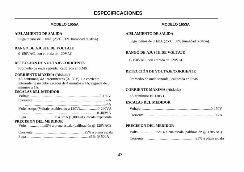
AISLAMIENTO DE SALIDA Fuga menos de 0.1mA (25°C, 50% humedad relativa).
RANGO DE AJUSTE DE VOLTAJE 0-150VAC, con entrada de 120VAC
DETECCIÓN DE VOLTAJE/CORRIENTE Promedio de onda senoidal, calibrada en RMS
CORRIENTE MÁXIMA (Aislada) 3A continuos, 4A intermitentes (0-130V). La corriente intermitente no debe exceder de 4 minutos a 4A, seguida de 5 minutos a 1A.
ESCALAS DEL MEDIDOR Voltaje: ..........................................................................0-150V Corriente: ...........................................................................0-2A .....................................................................................0-4A Volts-Amps (Voltaje establecido a 120V)...................0-240VA .................................................................................0-480VA Fuga ...............................0 a 5mA (5,000µA), escala expandida PRECISION DEL MEDIDOR Volts: .................±5% a plena escala (calibración @ 120VAC)
Corriente: ......................................................±5% a plena escala Fuga ...................................................................±5% @ 500A
MODELO 1653A
AISLAMIENTO DE SALIDA
Fuga menos de 0.1mA (25°C, 50% humedad relativa).
RANGO DE AJUSTE DE VOLTAJE
0-150VAC, con entrada de 120VAC
DETECCIÓN DE VOLTAJE/CORRIENTE
Promedio de onda senoidal, calibrada en RMS
CORRIENTE MÁXIMA (Aislada)
2A continuos (0-130V).
ESCALAS DEL MEDIDOR
Voltaje: ..........................................................................0-150V
Corriente: ...........................................................................0-2A
PRECISION DEL MEDIDOR
Volts: .................±5% a plena escala (calibración @ 120VAC)
Corriente: ......................................................±5% a plena escala
ESPECIFICACIONES
44
MODELO 1655A
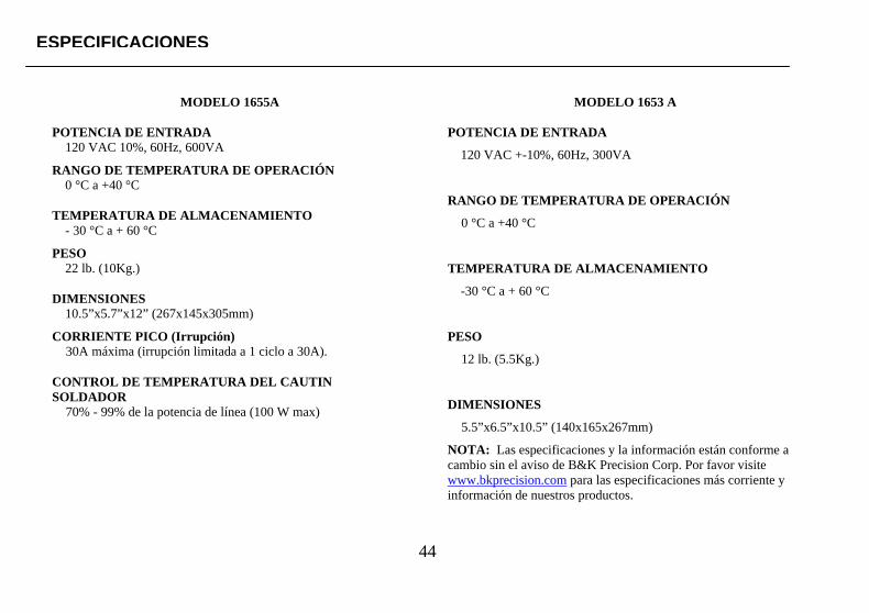
POTENCIA DE ENTRADA
120 VAC 10%, 60Hz, 600VA RANGO DE TEMPERATURA DE OPERACIÓN
0 °C a +40 °C TEMPERATURA DE ALMACENAMIENTO
- 30 °C a + 60 °C PESO
22 lb. (10Kg.) DIMENSIONES
10.5”x5.7”x12” (267x145x305mm) CORRIENTE PICO (Irrupción) 30A máxima (irrupción limitada a 1 ciclo a 30A). CONTROL DE TEMPERATURA DEL CAUTIN SOLDADOR 70% - 99% de la potencia de línea (100 W max)
MODELO 1653 A
POTENCIA DE ENTRADA
120 VAC +-10%, 60Hz, 300VA
RANGO DE TEMPERATURA DE OPERACIÓN
0 °C a +40 °C
TEMPERATURA DE ALMACENAMIENTO
-30 °C a + 60 °C
PESO
12 lb. (5.5Kg.)
DIMENSIONES
5.5”x6.5”x10.5” (140x165x267mm)
NOTA: Las especificaciones y la información están conforme a cambio sin el aviso de B&K Precision Corp. Por favor visite www.bkprecision.com para las especificaciones más corriente y información de nuestros productos.
ESPECIFICACIONES
45
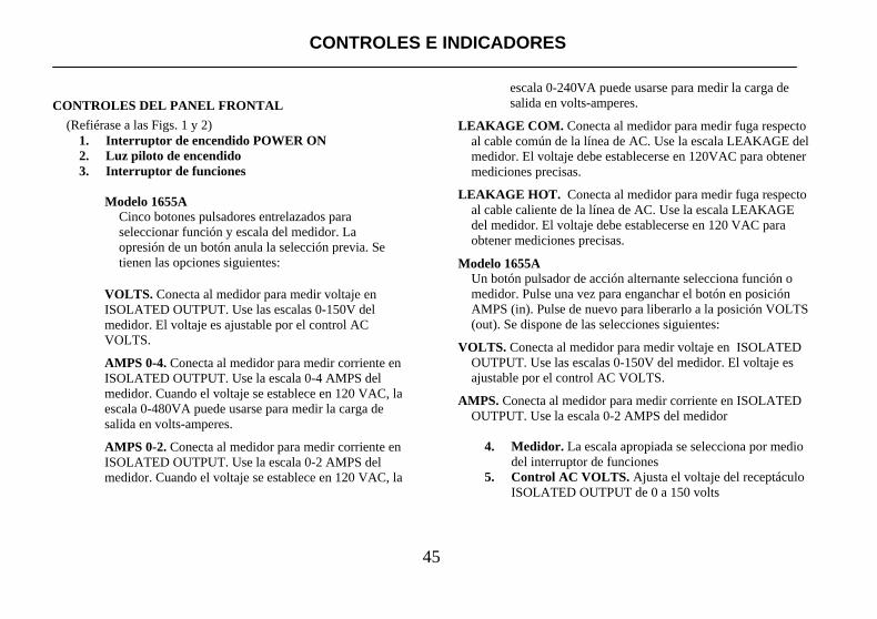
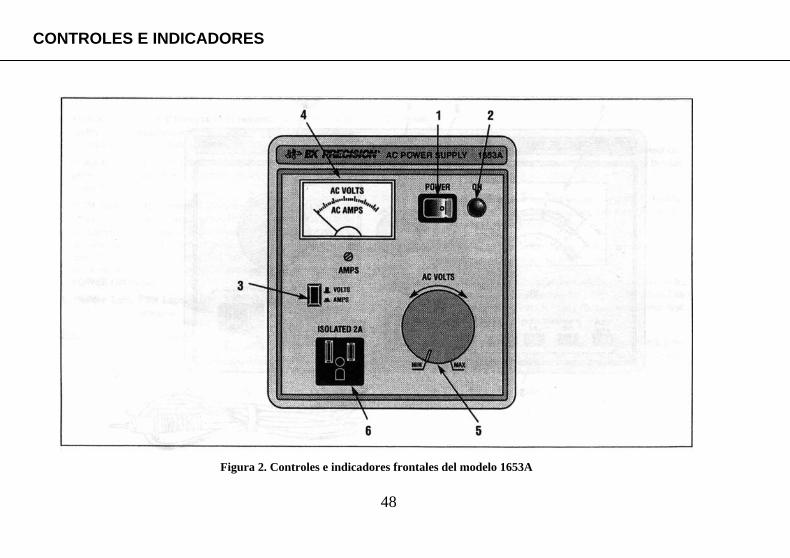
CONTROLES DEL PANEL FRONTAL (Refiérase a las Figs. 1 y 2)
1. Interruptor de encendido POWER ON 2. Luz piloto de encendido 3. Interruptor de funciones
Modelo 1655A
Cinco botones pulsadores entrelazados para seleccionar función y escala del medidor. La opresión de un botón anula la selección previa. Se tienen las opciones siguientes:
VOLTS. Conecta al medidor para medir voltaje en ISOLATED OUTPUT. Use las escalas 0-150V del medidor. El voltaje es ajustable por el control AC VOLTS. AMPS 0-4. Conecta al medidor para medir corriente en ISOLATED OUTPUT. Use la escala 0-4 AMPS del medidor. Cuando el voltaje se establece en 120 VAC, la escala 0-480VA puede usarse para medir la carga de salida en volts-amperes. AMPS 0-2. Conecta al medidor para medir corriente en ISOLATED OUTPUT. Use la escala 0-2 AMPS del medidor. Cuando el voltaje se establece en 120 VAC, la
escala 0-240VA puede usarse para medir la carga de salida en volts-amperes.
LEAKAGE COM. Conecta al medidor para medir fuga respecto al cable común de la línea de AC. Use la escala LEAKAGE del medidor. El voltaje debe establecerse en 120VAC para obtener mediciones precisas.
LEAKAGE HOT. Conecta al medidor para medir fuga respecto
al cable caliente de la línea de AC. Use la escala LEAKAGE del medidor. El voltaje debe establecerse en 120 VAC para obtener mediciones precisas.
Modelo 1655A
Un botón pulsador de acción alternante selecciona función o medidor. Pulse una vez para enganchar el botón en posición AMPS (in). Pulse de nuevo para liberarlo a la posición VOLTS (out). Se dispone de las selecciones siguientes:
VOLTS. Conecta al medidor para medir voltaje en ISOLATED
OUTPUT. Use las escalas 0-150V del medidor. El voltaje es ajustable por el control AC VOLTS.
AMPS. Conecta al medidor para medir corriente en ISOLATED
OUTPUT. Use la escala 0-2 AMPS del medidor
4. Medidor. La escala apropiada se selecciona por medio del interruptor de funciones
5. Control AC VOLTS. Ajusta el voltaje del receptáculo ISOLATED OUTPUT de 0 a 150 volts
CONTROLES E INDICADORES

46
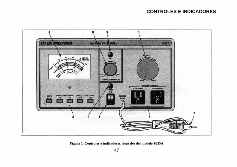
6. RECEPTÁCULO DE ISOLATED OUTPUT. Salidas aisladas de voltaje ac variable. Aquí se conecta el equipo bajo prueba. Una salida en el modelo 1653A. Dos salidas en el modelo 1655A.
7. *Punta de prueba de fuga. Al seleccionar la función
LEAKAGE, se prueba la fuga de la línea tocando con la punta diversas partes metálicas expuestas del equipo.
8. *Control SOLDER TEMP. La rotación completa en
sentido contrario a las manecillas del reloj de la perilla apaga la salida del cautín soldador. Una rotación inicial en el sentido de las manecillas enciende la salida a una temperatura de reserva (tibia); una rotación mayor incrementa la temperatura del cautín. El ajuste de temperatura es progresivo, permitiendo el ajuste fino de temperatura “caliente” al límite superior del rango. Este control es completamente independiente del de encendido POWER ON.
9. *Luz piloto de Solder Temp. Se enciende cuando la
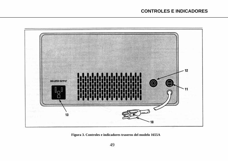
salida de cautín en el panel trasero está activada. CONTROLES DEL PANEL TRASERO (Refiérase a las Figs. 3 y 4)
10. Cable de AC *=Modelo 1655A solamente
11. Fusible Modelo 1655A El fusible de 4A protege al auto-transformador contra corrientes de salida excesivas a voltajes bajos que no alcancen a accionar al interruptor (“breaker”) de entrada. Modelo 1653A Un fusible de línea de 3A protege contra corrientes de entrada excesivas. Un fusible interno de 3A protege contra corrientes de salida excesivas a voltajes bajos que no alcancen a fundir el fusible de entrada.
12. *Interruptor de circuito de entrada (“breaker”).
Este interruptor de 3.15A protege contra corrientes excesivas. Remueva la sobrecarga y presione para restaurar.
13. *Clavija del cautín soldador. Clavija de AC para el
cautín. El factor de trabajo, y por tanto, la temperatura, puede variarse mediante el control SOLDER TEMP del panel frontal. Opera para cautines sin transformador de 100 watts o menos.
*=Modelo 1655A solamente
CONTROLES E INDICADORES
47
CONTROLES E INDICADORES
Figura 1. Controles e indicadores frontales del modelo 1655A
48
CONTROLES E INDICADORES
Figura 2. Controles e indicadores frontales del modelo 1653A
49
CONTROLES E INDICADORES
Figura 3. Controles e indicadores traseros del modelo 1655A

50
CONTROLES E INDICADORES
Figura 4. Controles e indicadores del modelo 1653A
51
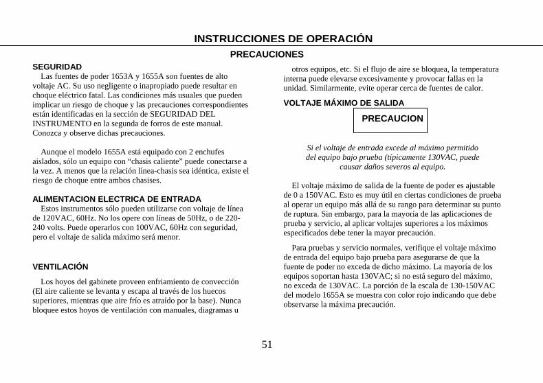
SEGURIDAD
Las fuentes de poder 1653A y 1655A son fuentes de alto voltaje AC. Su uso negligente o inapropiado puede resultar en choque eléctrico fatal. Las condiciones más usuales que pueden implicar un riesgo de choque y las precauciones correspondientes están identificadas en la sección de SEGURIDAD DEL INSTRUMENTO en la segunda de forros de este manual. Conozca y observe dichas precauciones.
Aunque el modelo 1655A está equipado con 2 enchufes aislados, sólo un equipo con “chasis caliente” puede conectarse a la vez. A menos que la relación línea-chasis sea idéntica, existe el riesgo de choque entre ambos chasises. ALIMENTACION ELECTRICA DE ENTRADA
Estos instrumentos sólo pueden utilizarse con voltaje de línea de 120VAC, 60Hz. No los opere con líneas de 50Hz, o de 220-240 volts. Puede operarlos con 100VAC, 60Hz con seguridad, pero el voltaje de salida máximo será menor.
VENTILACIÓN
Los hoyos del gabinete proveen enfriamiento de convección (El aire caliente se levanta y escapa al través de los huecos superiores, mientras que aire frío es atraído por la base). Nunca bloquee estos hoyos de ventilación con manuales, diagramas u
otros equipos, etc. Si el flujo de aire se bloquea, la temperatura interna puede elevarse excesivamente y provocar fallas en la unidad. Similarmente, evite operar cerca de fuentes de calor.
VOLTAJE MÁXIMO DE SALIDA
PRECAUCION
Si el voltaje de entrada excede al máximo permitido del equipo bajo prueba (típicamente 130VAC, puede
causar daños severos al equipo.
El voltaje máximo de salida de la fuente de poder es ajustable de 0 a 150VAC. Esto es muy útil en ciertas condiciones de prueba al operar un equipo más allá de su rango para determinar su punto de ruptura. Sin embargo, para la mayoría de las aplicaciones de prueba y servicio, al aplicar voltajes superiores a los máximos especificados debe tener la mayor precaución.
Para pruebas y servicio normales, verifique el voltaje máximo de entrada del equipo bajo prueba para asegurarse de que la fuente de poder no exceda de dicho máximo. La mayoría de los equipos soportan hasta 130VAC; si no está seguro del máximo, no exceda de 130VAC. La porción de la escala de 130-150VAC del modelo 1655A se muestra con color rojo indicando que debe observarse la máxima precaución.
INSTRUCCIONES DE OPERACIÓNPRECAUCIONES

52
Seleccione función VOLTS
Lea voltaje enescala o-150V Del medidor
EQUIPO
BAJO PRUEBA
Ajuste el voltaje, observe precaución si el
Voltaje excede el máximo del equipo bajo
Prueba. (El equipo puede dañarse seriamente)
La porción roja de la escala de VOLTS
indica zona de precaución
Figura 5. Observe precaución arriba de 130V
Precauciones INSTRUCCIONES DE OPERACIÓN

53
CORRIENTE MÁXIMA DE SALIDA
PRECAUCION
NUNCA EXCEDA EL VALOR DE CORRIENTE MÁXIMA DE SALIDA DE LA UNIDAD (Tabla 1) La corriente de salida en exceso puede dañar al
Auto-transformador variable Mantenga la corriente de salida tan baja como sea posible.
Conecte sólo un equipo a la vez. Use la salida ISOLATED OUTPUT sólo para el equipo bajo prueba – No para equipo de medición.
Es muy importante observar la disminución de la corriente máxima (Tabla 1) arriba de 130V, y permitir suficiente tiempo de enfriamiento al operar el modelo 1655A en la región de ciclo intermitente.
Aún a voltajes bajos, la corriente de salida máxima nunca debe exceder de 4 Amps en el modelo 1655A o 2 Amps en el modelo 1653A. Corrientes mayores pueden dañar al auto- transformador donde la escobilla hace contacto con el embobinado. El interruptor de entrada tipo “breaker” de 3.15A limita la corriente de entrada del 1655A, mientras que un fusible de 3 A se usa en el 1653A. Además, se cuenta con fusibles de salida de 4 A para el 1655A y de 3 A para el 1653A a bajos voltajes que no abren el “breaker” de entrada. Nunca cortocircuite el interruptor de entrada o los fusibles, o reemplace éstos por fusibles de mayor valor.
Remueva la fuente de sobrecarga para restaurar el “breaker” o reemplazar un fusible. Apague la unidad al conectar o desconectar equipos del receptáculo ISOLATED OUTPUT.
Para el modelo 1655A, la porción en rojo de la escala 0-4A del medidor indica la zona de precaución (Arriba de 3A). Esto le recordará que sólo se permite la operación de trabajo intermitente.
Para el modelo 1653A la corriente de salida no debe exceder de 2A para operación continua o intermitente. La indicación de 2A en el tope de la escala le indicará que ésta es la corriente de salida máxima permisible.
INSTRUCCIONES DE OPERACIÓN Precauciones
Tabla 1. Disminución de la corriente máxima de salida

54
INSTRUCCIONES DE OPERACIÓN Precauciones
MODELO 1655A La porción roja de la escala 0-4 A indica zona de precaución No exceda de 3A de regimen Continuo; de lo contrario podrá Dañar severamente a la fuente de AC.
CONSULTE EL TEXTO PARA REGIMEN INTERMITENTE Y DISMINUCIÓN REQUERIDA ARRIBA DE 130V.
MODELO 1653A No exceda del tope de la escala (2A) de regimen continuo. De lo contrario podrá dañar severamente la fuente de AC.
EQUIPO BAJO
PRUEBA Selección la Función AMPS
Figura 6. Consideraciones sobre la corriente máxima
La porción roja de la escala 0-4 A indica zona de precaución No exceda de 3A de regimen Continuo; de lo contrario podrá Dañar severamente a la fuente de AC.
CONSULTE EL TEXTO PARA REGIMEN INTERMITENTE Y DISMINUCIÓN REQUERIDA ARRIBA DE 130V.
Modelo 1655A
Modelo 1653A
EQUIPO BAJO
PRUEBA
MODELO 1655A

55
EL RIESGO La mayoría de los equipos con clavija de 2 puntas no poseen transformador
La mayoría de los televisores modernos y otros productos de consumo como amplificadores estéreo, sintonizadores, grabadoras, etc. no contienen un transformador de aislamiento. Estos productos tienen usualmente un gabinete de plástico o madera que aíslan totalmente al chasis y evitan que el usuario lo toque. Sin embargo, al remover el gabinete para dar servicio al producto, el chasis queda expuesto y representa un riesgo de choque eléctrico para el técnico de servicio. Rectificador de puente sin transformador
Uno de los tipos más usados para circuitos de fuentes de poder en televisores y equipos de audio es el rectificador de puente mostrado en la Fig. 7. En dichos casos el chasis está siempre “caliente” independientemente de la forma como se inserten las 2 puntas de la clavija en el enchufe de ac. El tocar un chasis “caliente” es riesgoso y puede causar un choque eléctrico fatal.
ADVERTENCIA
El que una unidad utilice una clavija polarizada no garantiza seguridad. Algunos equipos con un rectificador de puente usan clavija polarizada y,
como se mencionó arriba, tienen un chasis “caliente”
Equipos con rectificadores de media onda sin transformador Otro circuito común para circuitos de fuentes de poder sin
transformador es el rectificador de media onda en el que un lado de la línea de ac se conecta directamente al chasis (mostrado también en la Fig. 7). A menos que el equipo incluya una clavija polarizada para impedir que se inserte de la manera equivocada, el chasis puede ser “caliente” (120VAC respecto a tierra) y causar un choque eléctrico al tocarlo.
Otros riesgos en equipos sin transformador.
Equipos con fuentes del tipo doblador de voltaje pueden también poseer chasis “caliente” y presentar el mismo riesgo de seguridad. De hecho, cualquier equipo con clavija de 2 puntas debe tratarse como de riesgo, y será necesario tomar las precauciones enlistadas en la página siguiente.
Riesgo de daño a equipos de prueba Además del riesgo de choque eléctrico al tocar un chasis
“caliente”, existe una alta probabilidad de dañar cualquier instrumento de prueba con toma de ac utilizado para dar servicio al equipo. La mayoría de los equipos de prueba con clavija de 3 puntas, como osciloscopios o generadores de señal, tienen el chasis conectado a tierra a través de la tercera punta de la clavija. Al conectar dicha punta aterrizada a un chasis “caliente” se establece un cortocircuito entre la salida caliente de la línea de ac con la punta de tierra física e instrumento. Dado que la ruta a través del instrumento actúa sólo como tierra de la señal, la corriente excesiva del cortocircuito puede dañar extensivamente al instrumento o al equipo bajo prueba.
Localizando averías: Uso como transformador de aislamiento INSTRUCCIONES DE OPERACIÓN
LOCALIZANDO AVERÍAS: USO COMO TRANSFORMADOR DE AISLAMIENTO

56
INSTRUCCIONES DE OPERACIÓN Localizando averías: Uso como transformador de aislamiento

57
LA SOLUCION
No aterrice el chasis El conectar el chasis a una buena tierra por medio de una punta
de prueba no es una solución satisfactoria. Si el chasis es “caliente”, se establece un corto entre el lado “caliente” de la línea de ac y tierra. Uno estaría esperanzado de que el interruptor tipo “breaker” actúe, cortando el suministro de voltaje del enchufe. Pero dicho enchufe es una fuente de muy alta energía, y antes de actúe el “breaker” la punta de prueba puede desintegrarse o fundirse, y el equipo bajo prueba podría sufrir daños severos.
Utilice un transformador de aislamiento Para dar servicio a equipo de chasis “caliente”, conecte siempre un transformador de aislamiento entre la clavija de pared y el equipo bajo prueba. Los modelos 1653A y 1655A incluyen un transformador de aislamiento además de otras características. Como se muestra en la Fig. 8, al usar un transformador de aislamiento el chasis del equipo bajo prueba queda aislado eléctricamente de ambos lados de la línea de alimentación. Dicho chasis puede no ser conectado a tierra física con una punta de prueba.
Resumen Cualquier equipo con clavija de 2 puntas puede ser del tipo de chasis “caliente”, aún cuando incluya una clavija polarizada. Si incluye su propio transformador de aislamiento, no sobra usar el del instrumento. Por tanto, para mayor seguridad, trate a todo equipo con clavija de 2 puntas como del tipo de chasis “caliente”
y use la salida ISOLATED OUTPUT de la fuente de poder 1655A o 1653A para dar servicio al equipo.
PROCEDIMIENTO (Refiérase a la Fig. 9)
1. Apague la fuente de poder 1653A o 1655A y establezca el control AC VOLTS a MIN.
2. Conecte el enchufe de la fuente de poder al receptáculo de pared de 120 volts, 60Hz. El receptáculo debe ser de 3 puntas con el tercer cable conectado a una buena tierra física.
3. Si requiere un instrumento de medición accionado por ac, conéctelo a un receptáculo de pared de ac (No use el enchufe ISOLATED OUTPUT para instrumentos de prueba).
4. Conecte la clavija del equipo bajo prueba al receptáculo ISOLATED OUTPUT. Esto provee el aislamiento como se muestra en la Fig. 8.
ADVERTENCIA CONECTE SÓLO UN EQUIPO DE CHASIS CALIENTE
A LA VEZ. Existe un riesgo de choque entre 2 chasises a menos que ambos tengan una relación línea a chasis
idéntica. 5. Encienda la fuente con el control POWER ON. 6. Seleccione la función VOLTS y ajuste el control AC
VOLTS al voltaje deseado (típicamente 120V). 7. Se recomienda que el chasis del equipo bajo prueba se
aterrice con una punta de prueba.
Localizando averías: Uso como transformador de aislamiento INSTRUCCIONES DE OPERACIÓN
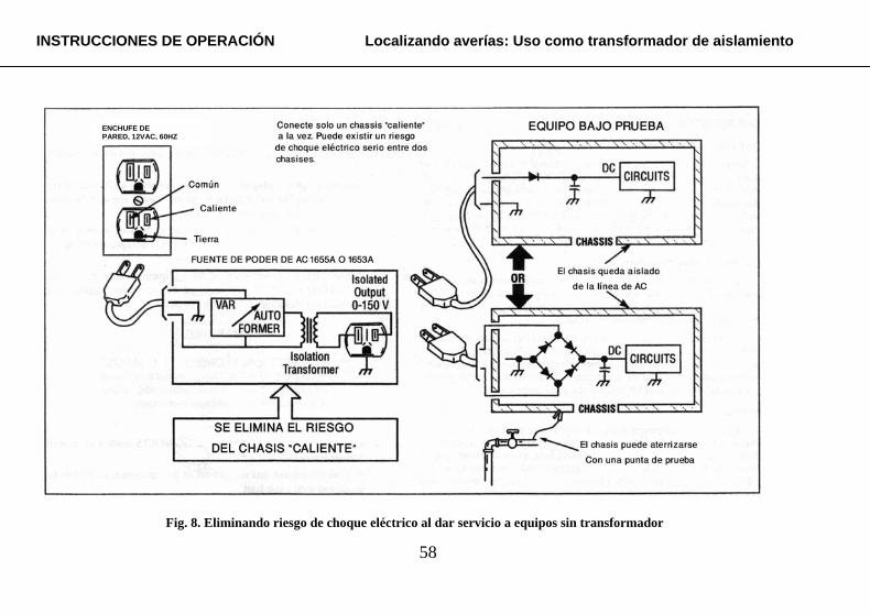
58
INSTRUCCIONES DE OPERACIÓN Localizando averías: Uso como transformador de aislamiento
Fig. 8. Eliminando riesgo de choque eléctrico al dar servicio a equipos sin transformador
ENCHUFE DEPARED, 12VAC, 60HZ
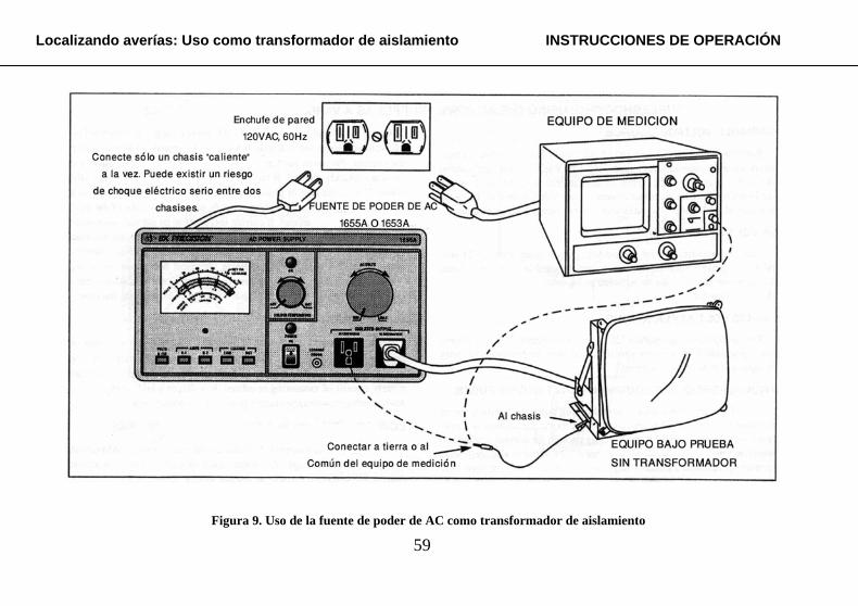
59
Localizando averías: Uso como transformador de aislamiento INSTRUCCIONES DE OPERACIÓN
Figura 9. Uso de la fuente de poder de AC como transformador de aislamiento
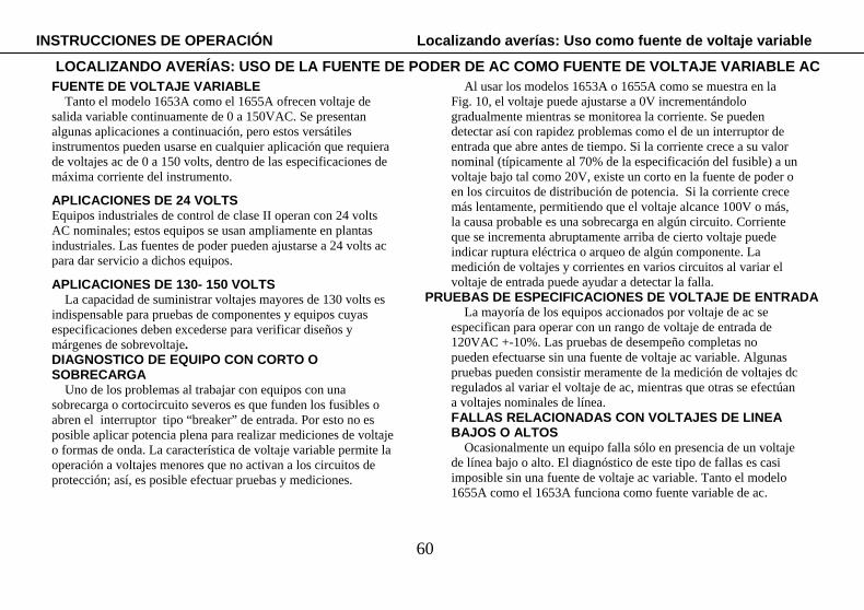
60
FUENTE DE VOLTAJE VARIABLE Tanto el modelo 1653A como el 1655A ofrecen voltaje de
salida variable continuamente de 0 a 150VAC. Se presentan algunas aplicaciones a continuación, pero estos versátiles instrumentos pueden usarse en cualquier aplicación que requiera de voltajes ac de 0 a 150 volts, dentro de las especificaciones de máxima corriente del instrumento.
APLICACIONES DE 24 VOLTS Equipos industriales de control de clase II operan con 24 volts AC nominales; estos equipos se usan ampliamente en plantas industriales. Las fuentes de poder pueden ajustarse a 24 volts ac para dar servicio a dichos equipos.
APLICACIONES DE 130- 150 VOLTS La capacidad de suministrar voltajes mayores de 130 volts es
indispensable para pruebas de componentes y equipos cuyas especificaciones deben excederse para verificar diseños y márgenes de sobrevoltaje. DIAGNOSTICO DE EQUIPO CON CORTO O SOBRECARGA
Uno de los problemas al trabajar con equipos con una sobrecarga o cortocircuito severos es que funden los fusibles o abren el interruptor tipo “breaker” de entrada. Por esto no es posible aplicar potencia plena para realizar mediciones de voltaje o formas de onda. La característica de voltaje variable permite la operación a voltajes menores que no activan a los circuitos de protección; así, es posible efectuar pruebas y mediciones.
Al usar los modelos 1653A o 1655A como se muestra en la Fig. 10, el voltaje puede ajustarse a 0V incrementándolo gradualmente mientras se monitorea la corriente. Se pueden detectar así con rapidez problemas como el de un interruptor de entrada que abre antes de tiempo. Si la corriente crece a su valor nominal (típicamente al 70% de la especificación del fusible) a un voltaje bajo tal como 20V, existe un corto en la fuente de poder o en los circuitos de distribución de potencia. Si la corriente crece más lentamente, permitiendo que el voltaje alcance 100V o más, la causa probable es una sobrecarga en algún circuito. Corriente que se incrementa abruptamente arriba de cierto voltaje puede indicar ruptura eléctrica o arqueo de algún componente. La medición de voltajes y corrientes en varios circuitos al variar el voltaje de entrada puede ayudar a detectar la falla.
PRUEBAS DE ESPECIFICACIONES DE VOLTAJE DE ENTRADA La mayoría de los equipos accionados por voltaje de ac se
especifican para operar con un rango de voltaje de entrada de 120VAC +-10%. Las pruebas de desempeño completas no pueden efectuarse sin una fuente de voltaje ac variable. Algunas pruebas pueden consistir meramente de la medición de voltajes dc regulados al variar el voltaje de ac, mientras que otras se efectúan a voltajes nominales de línea. FALLAS RELACIONADAS CON VOLTAJES DE LINEA BAJOS O ALTOS
Ocasionalmente un equipo falla sólo en presencia de un voltaje de línea bajo o alto. El diagnóstico de este tipo de fallas es casi imposible sin una fuente de voltaje ac variable. Tanto el modelo 1655A como el 1653A funciona como fuente variable de ac.
INSTRUCCIONES DE OPERACIÓN Localizando averías: Uso como fuente de voltaje variable
LOCALIZANDO AVERÍAS: USO DE LA FUENTE DE PODER DE AC COMO FUENTE DE VOLTAJE VARIABLE AC
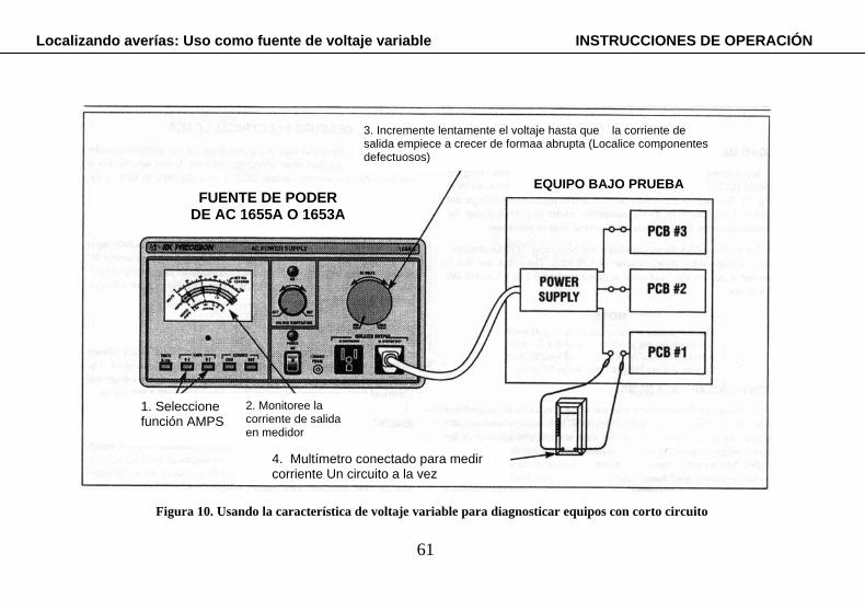
61
Enchufe de pared 120VAC, 60Hz
Localizando averías: Uso como fuente de voltaje variable INSTRUCCIONES DE OPERACIÓN
3. Incremente lentamente el voltaje hasta que la corriente de salida empiece a crecer de formaa abrupta (Localice componentes defectuosos)
EQUIPO BAJO PRUEBA
Figura 10. Usando la característica de voltaje variable para diagnosticar equipos con corto circuito
FUENTE DE PODER DE AC 1655A O 1653A
1. Seleccione función AMPS
2. Monitoree la corriente de salida en medidor
4. Multímetro conectado para medir corriente Un circuito a la vez

62
PROCEDIMIENTO DE MEDICION DE CARGA La medición de carga eléctrica es muy simple usando los modelos 1653A o 1655A como fuente de poder. Refiérase a la Fig. 11. El medidor incluido puede utilizarse para leer el voltaje y la corriente suministradas al equipo bajo prueba. El producto del voltaje por la corriente nos proporciona la carga en volts-amps.
Para el modelo 1655A el cálculo no se requiere si la medición se realiza al valor estándar de 120 volts. Las escalas de corriente 0-2A y 0-4A están también calibradas para lectura directa como escalas de 0-240VA y 0-480VA.
NOTA
Las escalas de VA son precisas sólo a 120 volts. Para otros voltajes use las escalas de corriente de 0-2A o 0-4A y calcule la
carga multiplicando el voltaje de salida por la corriente de salida.
APLICACIONES DE LOCALIZACIÓN DE AVERIAS Una verificación inicial de la carga eléctrica ayuda usualmente a detectar fallas de equipo electrónico. Si el equipo bajo prueba consume una corriente considerablemente menor a la normal, es posible que uno de los voltajes de la fuente esté ausente, inhabilitando varios circuitos. Si la corriente es superior a la normal, algún transistor u otro componnte podrían estar en corto. Si la corriente continúa arriba de lo normal después de corregir otras fallas, la sospecha recae en un capacitor defectuoso (con fuga). Estos problemas deben corregirse para prevenir otras fallas en consecuencia.
La carga eléctrica normal o la corriente de consumo del equipo bajo prueba están usualmente especificadas en su manual de servicio. Si dicha información no está disponible, la corriente de consumo típica es de 60% a 80% dela corriente especificada en el interruptor de entrada o fusible de línea.
APLICACIONES DE DISEÑO
Las metas de diseño de cualquier producto con entrada d ac incluye los requerimientos de potencia de entrada. El uso de la fuente de poder de ac para prueba de prototipos permite el monitoreo de la carga eléctrica para diversas configuraciones de circuitos, para un conjunto de voltajes y temperaturas.
PRUEBAS DE PRODUCCIÓN
Las pruebas finales de equipos eléctricos y electrónicos incluyen generalmente el monitoreo de la carga eléctrica en todos los modos de operación. Las fuentes de poder de ac B&K Precision proveen tanto el voltaje variable y las mediciones de carga requeridas para una estación de tales pruebas.
EFICIENCIA ENERGÉTICA
La eficiencia energética se ha convertido en una consideración importante para la selección de equipo. Un equipo es más eficiente cuanto menor es su carga eléctrica. La carga eléctrica de productos similares colocados en proximidad puede compararse para demostrar la eficiencia energética a un cliente.
INSTRUCCIONES DE OPERACIÓN Localizando averías: Medición de carga
LOCALIZANDO AVERÍAS: MEDICIÓN DE CARGA ELECTRICA USANDO LA FUENTE DE PODER DE AC

63
Localizando averías: Medición de carga INSTRUCCIONES DE OPERACIÓN
Fig. 11. Medición de carga eléctrica
1. Seleccione función VOLTS
4. Seleccione función AMPS
6. Multiplique Voltaje x Corriente para la carga eléctrica en VA. (Para el modelo 1655A a 120V sólo, lea la carga en VA directo del medidor)
EQUIPO BAJO
PRUEBA
3. Ajuste a 120V (o otro valor)
FUENTE DE PODER DE AC 1655A O 1653A
2. Monitoree el voltaje en el medidor
5. Monitoree la corriente En el medidor
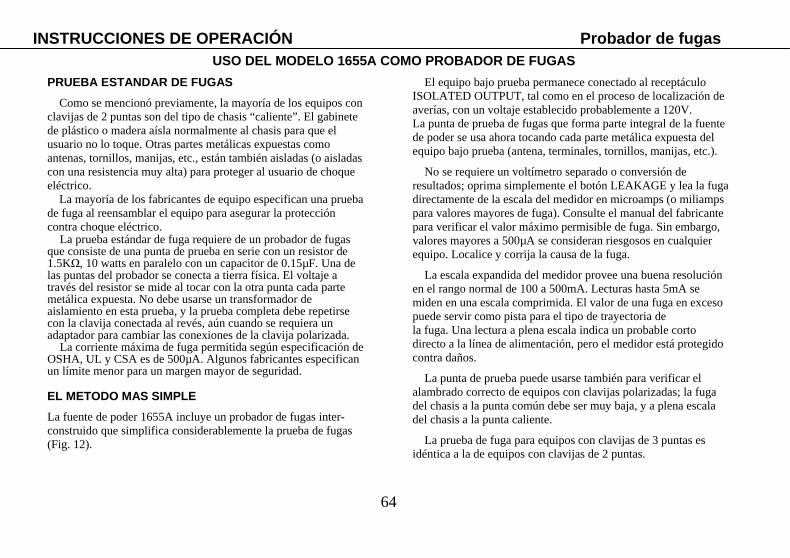
64
PRUEBA ESTANDAR DE FUGAS
Como se mencionó previamente, la mayoría de los equipos con clavijas de 2 puntas son del tipo de chasis “caliente”. El gabinete de plástico o madera aísla normalmente al chasis para que el usuario no lo toque. Otras partes metálicas expuestas como antenas, tornillos, manijas, etc., están también aisladas (o aisladas con una resistencia muy alta) para proteger al usuario de choque eléctrico.
La mayoría de los fabricantes de equipo especifican una prueba de fuga al reensamblar el equipo para asegurar la protección contra choque eléctrico.
La prueba estándar de fuga requiere de un probador de fugas que consiste de una punta de prueba en serie con un resistor de 1.5KΩ, 10 watts en paralelo con un capacitor de 0.15µF. Una de las puntas del probador se conecta a tierra física. El voltaje a través del resistor se mide al tocar con la otra punta cada parte metálica expuesta. No debe usarse un transformador de aislamiento en esta prueba, y la prueba completa debe repetirse con la clavija conectada al revés, aún cuando se requiera un adaptador para cambiar las conexiones de la clavija polarizada.
La corriente máxima de fuga permitida según especificación de OSHA, UL y CSA es de 500µA. Algunos fabricantes especifican un límite menor para un margen mayor de seguridad.
EL METODO MAS SIMPLE La fuente de poder 1655A incluye un probador de fugas inter-construido que simplifica considerablemente la prueba de fugas (Fig. 12).
El equipo bajo prueba permanece conectado al receptáculo ISOLATED OUTPUT, tal como en el proceso de localización de averías, con un voltaje establecido probablemente a 120V. La punta de prueba de fugas que forma parte integral de la fuente de poder se usa ahora tocando cada parte metálica expuesta del equipo bajo prueba (antena, terminales, tornillos, manijas, etc.).
No se requiere un voltímetro separado o conversión de resultados; oprima simplemente el botón LEAKAGE y lea la fuga directamente de la escala del medidor en microamps (o miliamps para valores mayores de fuga). Consulte el manual del fabricante para verificar el valor máximo permisible de fuga. Sin embargo, valores mayores a 500µA se consideran riesgosos en cualquier equipo. Localice y corrija la causa de la fuga.
La escala expandida del medidor provee una buena resolución
en el rango normal de 100 a 500mA. Lecturas hasta 5mA se miden en una escala comprimida. El valor de una fuga en exceso puede servir como pista para el tipo de trayectoria de la fuga. Una lectura a plena escala indica un probable corto directo a la línea de alimentación, pero el medidor está protegido contra daños.
La punta de prueba puede usarse también para verificar el alambrado correcto de equipos con clavijas polarizadas; la fuga del chasis a la punta común debe ser muy baja, y a plena escala del chasis a la punta caliente.
La prueba de fuga para equipos con clavijas de 3 puntas es
idéntica a la de equipos con clavijas de 2 puntas.
INSTRUCCIONES DE OPERACIÓN Probador de fugas USO DEL MODELO 1655A COMO PROBADOR DE FUGAS

65
Probador de fugas INSTRUCCIONES DE OPERACION
Figura 12. Prueba de fuga de la línea de alimentación
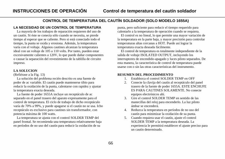
66
LA NECESIDAD DE UN CONTROL DE TEMPERATURA La mayoría de los trabajos de reparación requieren del uso de
un cautín. Si éste se conecta sólo cuando se necesita, se pierde tiempo al esperar que se caliente. Pero si está conectado todo el tiempo, la punta se oxida y erosiona. Además, la temperatura varía con el voltaje. Algunos cautines alcanzan la temperatura ideal con un voltaje de 105 a 110 volts. Por tanto, pueden estar excesivamente calientes a 120V, lo que puede dañar componentes o causar la separación del revestimiento de la tablilla de circuito impreso.
LA SOLUCION (Refiérase a la Fig. 13)
La solución del problema recién descrito es una fuente de poder de ac variable. El cautín puede mantenerse tibio para reducir la oxidación de la punta, calentarse con rapidez y ajustar la temperatura exacta deseada.
La fuente de poder 1655A incluye un receptáculo de ac separado en el panel trasero del aparato expresamente para el control de temperatura. El ciclo de trabajo de dicho receptáculo varía de 70% a 99%, y puede apagarse si el cautín no se usa. Icho receptáculo es exclusivo para cautines sin transformador, con potencia máxima de 100 watts.
La temperatura se ajusta con el control SOLDER TEMP del panel frontal. Se recomienda una temperatura relativamente baja en períodos de no uso del cautín para reducir la oxidación de su
punta, pero suficiente para reducir el tiempo requerido para calentarlo a la temperatura de operación cuando se requiera.
El control es no lineal, lo que permite una mayor variación de la temperatura en la parte baja, y mayor precisión para controlar temperaturas altas cercanas a HOT. Puede así lograr la temperatura exacta deseada fácilmente.
El control de temperatura es totalmente independiente de la salida de voltaje ISOLATED OUTPUT, incluyendo los interruptores de encendido-apagado y luces piloto separados. De esta manera, la característica de control de temperatura puede usarse con o sin las otras características del instrumento.
RESUMEN DEL PROCEDIMIENTO
1. Establezca el control SOLDER TEMP en OFF 2. Conecte la clavija del cautín al receptáculo del panel
trasero de la fuente de poder 1655A. ESTE ENCHUFE ES PARA CAUTINES SOLAMENTE. No conecte equipos electrónicos ahí.
3. Gire el control SOLDER TEMP en sentido de las manecillas del reloj para encenderlo. La luz piloto ámbar se encenderá.
4. Reduzca la temperatura en períodos de no uso del cautín para minimizar la oxidación de su punta.
5. Cuando requiera usar el cautín, ajuste el control SOLDER TEMP a la temperatura deseada. La experiencia le permitirá establecer el ajuste preciso para un cautín determinado.
INSTRUCCIONES DE OPERACIÓN Control de temperatura del cautín soldador
CONTROL DE TEMPERATURA DEL CAUTÍN SOLDADOR (SOLO MODELO 1655A)
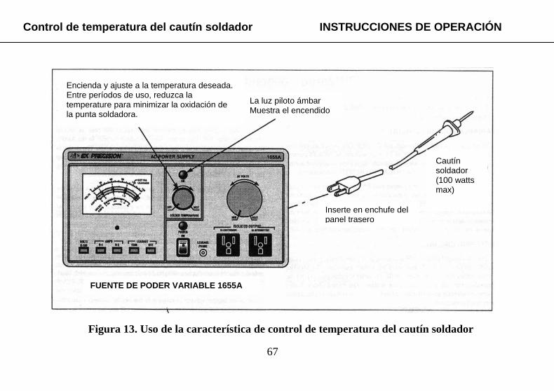
67
Control de temperatura del cautín soldador INSTRUCCIONES DE OPERACIÓN
Encienda y ajuste a la temperatura deseada. Entre períodos de uso, reduzca la temperature para minimizar la oxidación de la punta soldadora.
La luz piloto ámbar Muestra el encendido
Cautín soldador (100 watts max)
Inserte en enchufe del panel trasero
FUENTE DE PODER VARIABLE 1655A
Figura 13. Uso de la característica de control de temperatura del cautín soldador
68
Refiérase a los diagramas esquemáticos que se proveen separadamente al leer las descripciones del circuito siguientes. CIRCUITO DE VOLTAJE VARIABLE
La potencia de entrada se aplica a través de del interruptor POWER ON al auto-transformador variable T1. La salida de T1 se fija con el control AC VOLTS de 0 a 150 volts. El voltaje seleccionado se aplica a través del transformador de aislamiento T2 al receptáculo ISOLATED OUTPUT.
El modelo 1653A está protegido por el fusible de entrada F1 mientras que el 1655A usa el interruptor tipo “breaker” CB1, para limitar la corriente de entrada. El fusible F2 provee protección adicional para el auto-transformador, limitando la corriente máxima de salida a voltajes bajos que no abren al dispositivo protector del circuito de entrada. En el modelo 1655A el fusible es de 4 A en el panel trasero, y en el 1653A se usa un fusible interno de 3 A. CIRCUITO DE MEDICION
Dado que la salida de la unidad es ac, el medidor está conectado a través de un rectificador de puente para obtener el voltaje de dc requerido para su operación. El circuito rectificador detecta el nivel promedio, y el medidor se calibra para leer el valor rms de un voltaje senoidal. Los diodos conectados en oposición directamente a través del medidor limitan el voltaje máximo y ofrecen protección contra un sobrevoltaje.
Cuando se selecciona la función VOLTS, el voltaje presente en ISOLATED OUTPUT se aplica al circuito del medidor. El medidor está conectado en paralelo con un potenciómetro de ajuste fino VOLTAJE CAL para calibrar la escala de voltaje.
Un resistor de detección de corriente de 1 ohm (2 de 0.5 ohms en el modelo 1655A) desarrolla un voltaje proporcional a la corriente de salida. En la función AMPS, este voltaje se aplica a través del circuito del medidor, que queda ahora en paralelo con el potenciómetro de ajuste AMPS CAL para calibrar la escala de corriente de 2 amp. En el modelo 1655A la escala de 4 amps se selecciona detectando el voltaje desarrollado a través de sólo uno de los resistores de 5 ohms.
Cuando se selecciona la función LEAKAGE (Modelo 1655A solamente) la corriente de la punta de prueba se aplica al circuito del medidor. Los diodos D4 y D5 están polarizados en reversa debajo de 500µA para la característica de escala expandida. Para corrientes de fuga mayores, los diodos se polarizan en sentido directo y desvían parte de la corriente para comprimir la escala del medidor. CIRCUITO DE CONTROL DE TEMPERATURA DEL CAUTIN SOLDADOR
(Modelo 1655A solamente) La potencia de entrada se aplica a través del triac TR1 al enchufe del cautín en el panel trasero. El diodo de avalancha D1 no impulsa al triac a conducir sino hasta que se alcance el umbral de 30V. Así, el triac no conduce el ciclo de entrada completo. El control R2 SOLDER TEMP forma parte de un circuito RC de desplazamiento de fase que varía la fase del voltaje de disparo en relación con el voltaje del ánodo del triac. Esto varía el período de no conducción, lo que ajusta la temperatura del cautín. El circuito se restablece automáticamente cada vez que el voltaje ac pasa por cero.
DESCRIPCIÓN DEL CIRCUITO

69
ADVERTENCIA 1. Las instrucciones siguientes son para el uso de personal
calificado solamente Para evitar choque eléctrico, no preste servicio diferente al mencionado a menos que esté calificad
para efectuarlo. 2. Cuando la unidad se conecta a un enchufe de ac, aún cuando el interruptor de encendido esté en OFF, Hay voltaje de línea presente en algunos circuitos. Observe precaución
cuando remueva el gabinete. MANTENIMIENTO PREVENTIVO
No sobrecargue al instrumento. Corriente de salida excesiva puede dañar el auto-transformador variable. El uso prolongado a corrientes altas acelera las fallas. Mantenga dicha corriente tan baja como sea posible, y nunca exceda el valor máximo de la unidad. De ser posible, alimente sólo 1 equipo a la vez. Use la salida ISOLATED INPUT sólo para el equipo bajo prueba, no para otros instrumentos de medición. Es muy importante observar la disminución de la corriente máxima (Tabla 1) arriba de 130 volts, y permitir suficiente tiempo de enfriamiento al operar el modelo 1655A arriba de 3 amps.
Se recomienda revisar periódicamente la escobilla en los contactos variables del auto-transformador; las escobillas muy usadas o arqueadas deben reemplazarse. Consulte el párrafo REEMPLAZO DE LA ESCOBILLA DEL AUTO-TRANSFORMADOR para los procedimientos de reemplazo.
DEVOLUCIÓN PARA SERVICIO Si ha encontrado problemas con su unidad y determina
retornarla para servicio, verifique lo siguiente antes de su devolución:
1. ¿Está restablecido el interruptor de entrada (“breaker” del modelo 1655A)? Consulte REEMPLAZO DE FUSIBLES Abajo de requerirse.
2. ¿Están bien los fusibles? Consulte REEMPLAZO DE FUSIBLES abajo de requerirse.
REEMPLAZO DE FUSIBLES
La fuente de poder de ac abrirá su interruptor de entrada o fundirá un fusible sólo si se produce una sobrecarga severa o una falla en el instrumento. Apague siempre el aparato para restablecer el interruptor o reemplazar un fusible. Si los fusibles son internos, desconecte además el instrumento del enchufe de pared antes de efectuar el reemplazo. Antes de encender el aparato de nuevo, remueva la causa de la sobrecarga y disminuya el voltaje de salida. Reemplace el fusible dañado sólo con el tipo y valor originales – nunca de un valor mayor, que podría causar un incendio o riesgo de seguridad, o un daño serio al instrumento. Refiérase a la información específica de reemplazo de fusibles para cada modelo siguiente. Modelo 1653A
Si el instrumento sufre una sobrecarga severa a un voltaje alto de salida, el fusible F1 del panel trasero se fundirá. La unidad dejará de operar y la luz piloto se apagará. Si la sobrecarga ocurre
MANTENIMIENTO Y CALIBRACIÓN

70
a bajo voltaje, el fusible interno F2 se fundirá, no habrá voltaje de salida pero la luz piloto permanecerá encendida. La Fig. 14 muestra la localización de los fusibles. Reemplace el fusible F1 sólo con otro del tipo 3AG de lenta fusión de 3 amps, y el F2 sólo con uno de 3 amps de lenta fusión. Modelo 1655A
Si el instrumento sufre una sobrecarga severa a un voltaje alto de salida, el interruptor de entrada (“breaker”) CB1 se abrirá. La unidad dejará de operar y la luz piloto POWER ON se apagará. Remueva la sobrecarga y presione el botón de restablecimiento del interruptor Si la sobrecarga ocurre a bajo voltaje, el fusible interno F2 se fundirá, no habrá voltaje de salida pero la luz piloto permanecerá encendida. Si el receptáculo del cautín está sobrecargado, el fusible interno F1 se fundirá y se apagará la luz piloto SOLDER TEMP. La Fig. 15 muestra la localización de los fusibles. Reemplace el fusible F1 sólo con otro del tipo 3AG normal de 1 amp, y el F2 sólo con uno del tipo 3AG de 4 amps de lenta fusión. REEMPLAZO DE LA ESCOBILLA DEL AUTO-TRANSFORMADOR
Para reemplazar la escobilla, desconecte el instrumento y levante suavemente la escobilla de su pista. Agarre el ensamble de la escobilla vieja y jálelo fuera de posición radialmente.
Es imperativo que la instalación o reinstalación de una escobilla en su pista sea correcta para la operación adecuada del auto-transformador. Con el aparato apagado, inserte una pieza de papel de granate (no metálico) entre la escobilla y la pista, con el
lado rugoso hacia la escobilla. Al balancear la escobilla unas cuantas veces sobre el papel de granate podrá parear el contacto de la escobilla con la pista. Remueva el papel y todas las partículas sueltas antes de encender. AJUSTES DE CALIBRACIÓN
Esta unidad ha sido cuidadosamente revisada y calibrada en la fábrica antes de su embarque. Se recomienda ajustarla sólo si se han efectuado reparaciones en los circuitos que afectan su calibración, o si tiene razones para creer que se ha desajustado. La localización de los ajustes de calibración se muestran el la Fig. 14 y 15 para los modelos 1653A y 1655A respectivamente. Equipo de prueba requerido
1. Multímetro de ac con precisión de voltaje de 0.5% o mejor a 120V, 60Hz, y precisión de corriente de 1% o mejor a 500 microamps y 2 amps, 60Hz. Modelo 2831D de B+K Precision o equivalente.
2. Carga resistiva de 60 ohms, 240 watts, capaz de disipar corriente de 2 amps a 120 VAC. Puede usar una carga variable de la potencia suficiente, o focos en paralelo totalizando 240 watts.
MANTENIMIENTO Y CALIBRACIÓN

71
MANTENIMIENTO Y CALIBRACIÓN
Fusible F1 (Entrada)
T2 Transformador de Aislamiento
T1 Auto Transformador
Medidor
(VISTA LATERAL F2, R6&R7 VISTAS A TRAVES DE LA TABLILLA DE CIRCUITO IMPRESO)
Figura 14. Localización de fusibles y ajustes de calibración, Modelo 1653A

72
MANTENIMIENTO Y CALIBRACIÓN
Figura 15. . Localización de fusibles y ajustes de calibración, Modelo 1655A
73
Calibración de VOLTS del medidor 1. Con la fuente apagada, ajuste el cero mecánico del medidor a un
cero exacto. 2. Conecte un multímetro externo de precisión de voltaje de ±0.5%
o mejor a ISOLATED OUTPUT 3. Encienda la fuente de poder y establezca el voltaje mediante el
control AC VOLTS a 120 volts del multímetro 4. Establezca el interruptor de función a VOLTS y ajuste VOLTS
CAL (R6 para el modelo 1653A, R14 para el 1655A) a 120 volts en el medidor inter-construído.
Calibración de AMPS del medidor 1. Conecte una carga resistiva de 60 ohms, 240 watts a
ISOLATED OUTPUT. Focos en paralelo totalizando 240 watts es una carga adecuada.
2. Conecte un multímetro calibrado de precisión 1% o mejor en serie con la carga para medir cada corriente. Establezca el rango a 0-2 Amp.
3. Encienda la fuente de poder e incremente lentamente el voltaje de salida hasta que el multímetro indique 2.0A.
4. Establezca el interruptor de función a AMPS y ajuste AMPS CAL (R7 para el modelo 1653A, R12 para el 1655A) a 2.0 Amps en el medidor inter-construído.
5. Para el modelo 1655A, ajuste la calibración del rango 0-4A, y verifique después la precisión a media escala del rango 0-4 A. El ajuste calibra ambas escalas. Si el rango 0-4A no es preciso, reemplace R5 y R6 con resistors pareados iguales y repita el ajuste de calibración.
Calibración de LEAKAGE del medidor 1. Conecte la punta de prueba de fuga en serie con un resistor
de 220KΏ , ¼ watt 2. Conecte un multímetro de precisión de 1% o mejor en serie
con el resistor de 220KΏ, y la punta de prueba de fuga. Establezca el control del multímetro para medir una corriente de 500µA de ac.
3. Conecte con cuidado la otra punta del multímetro al lado caliente del enchufe ISOLATED OUTPUT. Ajuste el control AC VOLTS para exactamente 500µA en el multímetro.
4. Seleccione la función LEAKAGE y ajuste LEAKAGE CAL (R11) para 500µA en el medidor inter-construído.
Pruebas de desempeño Las verificaciones siguientes prueban la operación adecuada de
todas las funciones de la fuente de poder de ac. La secuencia de verificaciones siguen también una técnica lógica de búsqueda de fallas para determinar síntomas y aislar fallas. Después del diagnóstico y reparaciones correspondientes, ejecute estas pruebas para asegurarse de que todas las fallas han sido corregidas. 1. Antes de encender la fuente, el medidor debe indicar un cero
exacto. Si se requiere un ajuste mecánico, verifique de nuevo los ajustes de calibración.
2. Encienda el aparato mediante POWER ON. La luz piloto POWER ON debe encenderse.
3. Establezca la función VOLTS y gire el control AC VOLTS a su mínimo (contra las manecillas del reloj). La salida del medidor debe indicar cero volts.
MANTENIMIENTO CALIBRACIÓN

74
4. Gire ahora el control AC VOLTS a su máximo. La perilla debe girar suavemente y el voltaje de salida debe crecer también suavemente a 150 volts, indicados en el medidor. Para verificar su calibración, mida el voltaje con un voltímetro calibrado externo a 120 volts y compárelo con el medidor interno del panel frontal.
5. Reduzca el voltaje a su mínimo y conecte una carga a ISOLATED OUTPUT. Se prefiere un arreglo de focos de 240 watts. Establezca el interruptor de función a AMPS e incremente AC VOLTS hasta que el medidor indique 2 amps (o 120 volts, lo que ocurra primero). Para verificar la calibración del medidor, mida la corriente con un medidor calibrado externo a 2.0 amps y compare la lectura con la del medidor interno.
6. Para el modelo 1655A verifique que el medidor indica 2 amps tanto en la escala de 0-2A como en la de 0-4A.
7. Para el modelo 1655A, verifique la función de fuga como sigue: a. Reduzca el voltaje a su mínimo y conecte la punta de
prueba al lado caliente de ISOLATED OUTPUT b. Seleccione la función LEAKAGE e incremente lentamente
el voltaje AC VOLTS hasta que el medidor indique 500 A en la escala de fuga. Esto debe ocurrir a unos 6 volts. Para verificar la calibración del medidor, mida la corriente de fuga con un medidor externo calibrado y compárela con la indicada en el medidor interno del panel frontal.
c. Incremente el voltaje con el control AC VOLYTS hasta que el medidor indique 5mA en la escala de fuga. Esto debe ocurrir a unos 60 volts. Con la polaridad inversa de la función LEAKAGE, el medidor debe indicar cero.
d. Cambie la punta de prueba al lado común de ISOLATED OUTPUT y seleccione las 2 polaridades de la función LEAKAGE. Una polaridad debe medir cero y la otra 5mA de fuga.
8. Para el modelo 1655A, verifique la función de control de temperatura del cautín como sigue: a. Conecte una carga al enchufe del cautín en el panel
trasero. Puede usar un cautín, aunque se prefiere un foco de 25 a 100 watts. Gire el control SOLDER TEMP; la luz piloto ámbar debe encenderse.
b. Conecte un voltímetro en paralelo con la carga y varía el control SOLDER TEMP del mínimo al máximo. Al voltaje de línea de 120 volts, la intensidad del foco debe variar y el voltímetro debe indicar un voltaje entre 85 volts y un máximo de 118 volts (esta variación se logra sólo con la carga conectada).
LOCALIZACIÓN DE FALLAS
Si las “pruebas de desempeño” recién descritas se llevan a cabo en la secuencia explicada, se estaría siguiendo un enfoque lógico para definir síntomas y aislar circuitos defectuosos. La información siguiente puede ayudar a detectar problemas con mayor precisión.
MANTENIMIENTO Y CALIBRACIÓN
75
La lámpara piloto POWER ON no enciende Este síntoma indica una falla del circuito de poder primario, o
un “breaker” abierto (modelo 1655A), o un fusible fundido (modelo 1653A). Las verificaciones siguientes le ayudarán a aislar el problema:
1. Asegúrese que la unidad está conectada a un enchufe “vivo”
2. Reestablezca el “breaker” (modelo 1655A) o verifique y reemplace el fusible del panel trasero si está fundido (modelo 1653A)
3. Si tanto ya sea el “breaker” o el fusible están bien, verifique si hay salida de la fuente; seleccione la función VOLTS y note la lectura del medidor en la escala 0-150V. Si hay salida, significa que la lámpara está probablemente fundida. Si no hay salida, el problema es probablemente un circuito abierto del circuito del transformador primario. Verifique la continuidad del cable de corriente, recptáculo del fusible, interruptor POWER ON, auto-transformador variable y el cableado que une dichas partes.
4. Si el “breaker” no se abre de nuevo, o el fusible no se funde al encender la unidad, el problema previo puede haber sido causado por una sobrecarga en ISOLATED OUTPUT.
5. Si el “breaker” se abre de nuevo o el fusible de reemplazo se funde, verifique si hay un corto en el auto-transformador variable o en el transformador de poder.
No hay salida aunque la lámpara piloto enciende 1. Si no hay indicación de voltaje de salida en el medidor,
verifique el voltaje en ISOLATED OUTPUT con un voltímetro externo.
2. Si no hay voltaje en el medidor externo, verifique el fusible trasero (Modelo 1655A) o el fusible interno F2 (modelo 1653A) y reemplácelos si están fundidos. En caso contrario, inspeccione la escobilla del auto-transformador. Verifique si hay un embobinado abierto en el transformador de aislamiento o una falla del resistor de detección de corriente.
3. Si existe voltaje en el medidor externo, vea el procedimiento de localización de averías del párrafo siguiente.
Lectura incorrecta o falta de lectura de VOLTS, AMPS o LEAKAGE en el medidor
1. Verifique las lecturas del medidor para las tres funciones para aislar la falla.
2. En caso de imprecisión, efectúe una ajuste de calibración. Si no hay lectura, o es imposible corregirla, significa que hay un componente defectuoso.
3. Si hay problemas en más de una función, verifique los diodos del rectificador de puente, el medidor y los resistores en serie. Si el problema se presenta sólo en una función, verifique el interruptor correspondiente y los resistores asociados.
Operación anormal de SOLDER TEMP (Modelo 1655A solamente)
1. Si no enciende el piloto SOLDER TEMP, verifique el fusible F1 y reemplácelo si está fundido. De lo contrario, verifique el voltaje del enchufe. Si está bien, es la lámpara piloto la defectuosa.
2. Si la lámpara está bien, pero no hay voltaje o éste es incorrecto, verifique el Triac TR1, diodo de avalancha D1, resistores R1, R2 y R3, capacitores C1 y C2, e inductor L1.
MANTENIMIENTO Y CALIBRACION

76
Información de Servicio
Servicio de Garantía: Por favor regrese el producto en el empaquetado original con prueba de la fecha de la compra a la dirección debajo. Indique claramente el problema en escritura, incluya todos los accesorios que se estan usado con el equipo. Servicio de No Garantía: Por favor regrese el producto en el empaquetado original con prueba de la fecha de la compra a la dirección debajo. Indique claramente el problema en escritura, incluya todos los accesorios que se estan usado con el equipo. Clientes que no tienen cuentas deben de incluir pago en forma de queque, orden de dinero, o numero de carta de crédito. Para los precisos mas corriente visite www.bkprecision.com y oprime “service/repair”. Vuelva toda la mercancía a B&K Precision Corp. con el envío pagado por adelantado. La carga global de la reparación para el servicio de la No-Garantía no incluye el envío de vuelta. El envío de vuelta a las localizaciones en norte americano es incluido para el servicio de la garantía. Para los envíos de noche y el envío del no-Norte los honorarios americanos satisfacen el contacto B&K Precision Corp. B&K Precision Corp. 22820 Savi Ranch Parkway Yorba Linda, CA 92887 www.bkprecision.com 714-921-9095 Incluya con el instrumento la dirección de vuelto para envío, nombre del contacto, número de teléfono y descripción del problema.

77
Garantía Limitada de Dos Años
B&K Precision Corp. Autorizaciones al comprador original que su productos y componentes serán libre de defectos por el periodo de dos años desde el día en que se compro. B&K Precision Corp. sin carga, repararemos o sustituir, a nuestra opción, producto defectivo o componentes. Producto devuelto tiene que ser acompañado con prueba de la fecha del la compra en la forma de un recibo de las ventas. Para obtener cobertura en los EE.UU., este producto debe ser registrado por medio de la forma de registro en www.bkprecision.com dentro de quince (15) días de la compra de este producto. Exclusiones: Esta garantía no se aplica en el evento de uso en error o abuso de este producto o el resultado de alteraciones desautorizado o reparaciones. La garantía es vacía si se altera, se desfigura o se quita el número de serie. B&K Precision Corp. no será obligado a dar servicio por danos consecuente, incluyendo sin limitaciones a danos resultando en perdida de uso. Algunos estados no permiten limitaciones de daños fortuitos o consecuentes. Tan la limitación o la exclusión antedicha puede no aplicarse a usted. Esta garantía le da ciertos derechos y pueden tener otros derechos, cuales cambian estado por estado. B&K Precision Corp. 22820 Savi Ranch Parkway Yorba Linda, CA 92887 www.bkprecision.com

Declaration of CE Conformityaccording to EEC directives and NF EN 45014 norm
Responsible Party Alternate Manufacturing Site
Manufacturer’s Name: B&K Precision Corporation B&K Taiwan 0574
Manufacture’s Address: 22820 Savi Ranch Pkwy.Yorba Linda, CA 92887-4610USA
Declares that the below mentioned product
Product Name: DC Power Supplies
Part Numbers: 1651A, 1652, 1653A, 1655A, 1710A, 1711A, 1715A, 1730A, 1735A, 1740A, 1740B, 1743A, 1744, 1745, 1745A, 1746A, 1760A, 1761
complies with the essential requirements of the following applicable European Directives:
Low Voltage Directive 73/23/EEC (19.02.73) amended by 93/68/EEC (22.07.93)Electromagnetic Compatibility (EMC) 89/336/EEC (03.05.88) amended by 92/68/EEC (22.07.93)
and conforms with the following product standards:
Safety EN 61010-1:2001
EMC EN 61326:1997 + A1:1998 + A2:2001EN 50081-1EN 50081-2
This Declaration of Conformity applies to above listed products place on the EU market after:
February 4, 2005Date Victor Tolan
President

22820 Savi Ranch Parkway Yorba Linda, CA 92887 www.bkprecision.com
© 2005 B&K Precision Corp.
80-770-9-001
39
4