instruction manual manuale d’istruzioni · · 2012-10-16mirror dispersion correction knob...
TRANSCRIPT

0
2WAJ
INSTRUCTION MANUAL MANUALE D’ISTRUZIONI
Ver. 2.0.1

1

2
- Description page 3
- Introduction page 5
- Contents of the Set page 6
- Technical Specifications page 6
- Function and Construction of the Refractometer page 6
- Using the Refractometer page 9
- Note about the mean dispersion value page 11
- Maintenance page 14
- Recovery and Recycling page 15
Index

3
Description
Reflecting mirror
Dispersion correction knob
Eyepiece
On/Off switch
Thermometer
System base
Thermometer socket
Refractive index graduation
adjustment knob
Shield
Fitting 1
Fitting 2
Fitting 4
Fitting 3
Dispersion scale

4
Description
Lock-knob
Incident prism
Refracting prism
Housing
Condenser

5
This refractometer is a scientific precision instrument designed to last for many years with a minimum of maintenance. It is built to high optical and mechanical standards and to withstand daily use. The instrument serves for measuring the refractive indices, nD, and mean dispersion values, nF-nC, of transparent and translucent liquids or solids. Attaching a thermostat to this instrument, the refractive indices, nD, within the range of temperature 0-70°C can be measured. Refractive indices and mean dispersions are important optical constants of a substance and can be used to determine the optical performance, purity, concentration and dispersion etc. Therefore, the refractometer is an indispensable tool within a wide range of industries, such as petrological, pharmaceutical, chemical and sugar making industries, as well as in factories, colleges and within research institutes. Optika reminds you that this manual contains important information on safety and maintenance, and that it must therefore be made accessible to the instrument users. Optika declines any responsibility deriving from instrument uses that do not comply with this manual.
1.0 Introduction
6
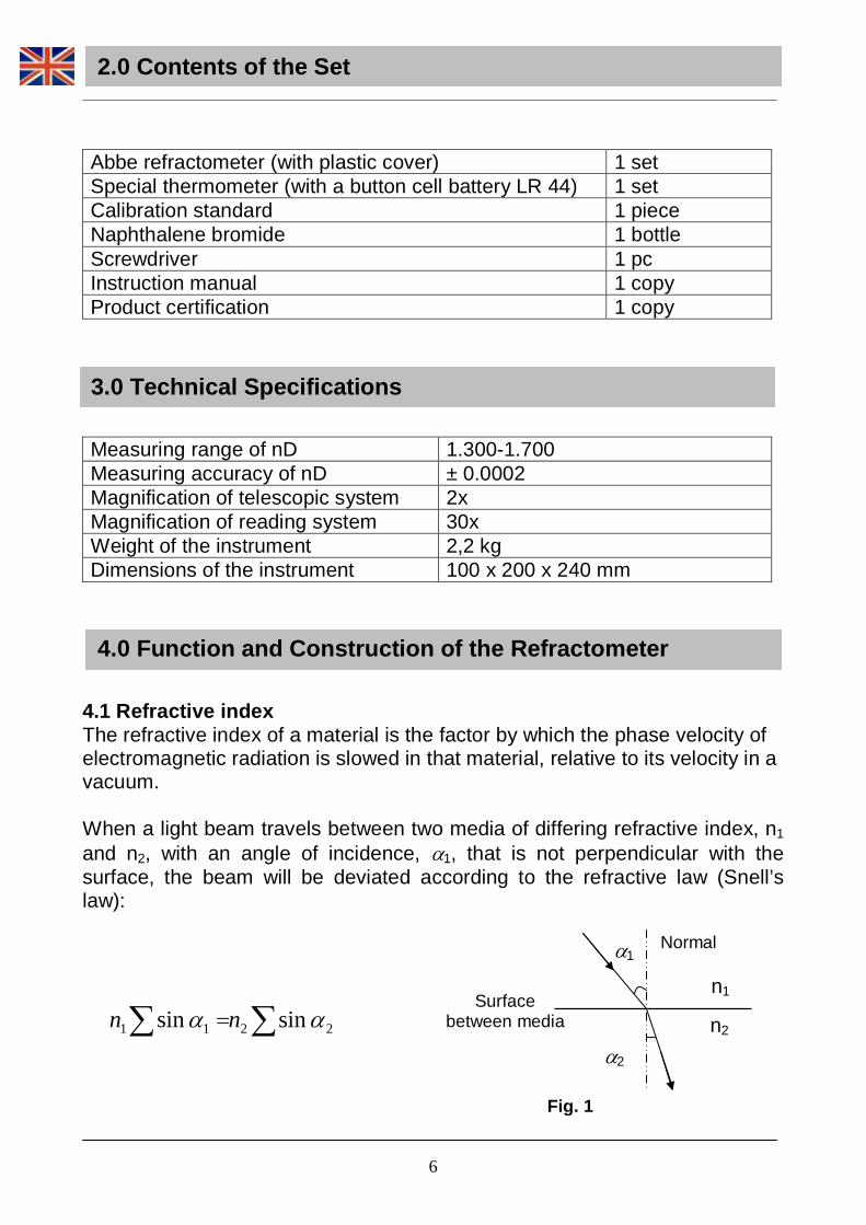
Abbe refractometer (with plastic cover) 1 set Special thermometer (with a button cell battery LR 44) 1 set Calibration standard 1 piece Naphthalene bromide 1 bottle Screwdriver 1 pc Instruction manual 1 copy Product certification 1 copy
Measuring range of nD 1.300-1.700 Measuring accuracy of nD ± 0.0002 Magnification of telescopic system 2x Magnification of reading system 30x Weight of the instrument 2,2 kg Dimensions of the instrument 100 x 200 x 240 mm
4.1 Refractive index The refractive index of a material is the factor by which the phase velocity of electromagnetic radiation is slowed in that material, relative to its velocity in a vacuum. When a light beam travels between two media of differing refractive index, n1 and n2, with an angle of incidence, α1, that is not perpendicular with the surface, the beam will be deviated according to the refractive law (Snell’s law):
2.0 Contents of the Set
3.0 Technical Specifications
4.0 Function and Construction of the Refracto meter
α1
Surface between media
α2
n1
n2
Fig. 1
∑∑ = 2211 sinsin αα nn
Normal

7
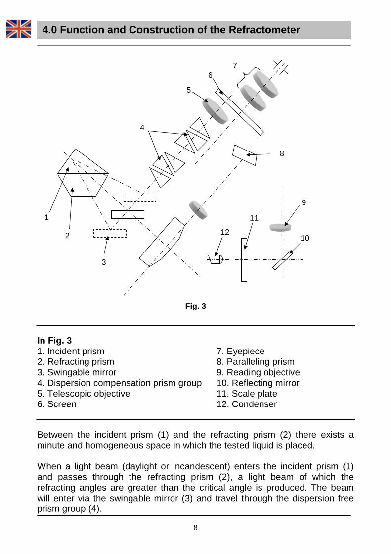
Where α2, is the angle of refraction measured with respect to the normal to the surface. When a light beam enters from optically denser medium to optically thinner one, the angle of incidence is smaller than the refractive angle. Increasing the angle of incidence will lead us to a point where the angle of refraction will be 90°C. In this case, the angle of incidence is calle d a critical angle. Beyond this angle total reflection will occur and no light will be transmitted to the second medium. This principle is used by the refractometer in order to determine the refractive indices. In the refractometer light beams from different angles fall upon the surface, its refractive angles are always greater than 90°. A telescope is used to observe the emerging beam and a bright and dark image can be observed in the field of view in the telescope, appearing as distinct boundary line in between, as indicated in fig. 2. The boundary line between the brightness and the darkness is just the position of the critical angle. 4.2 Construction of the optical system The optical system of the instrument consists of the telescopic and the reading systems as shown in fig. 3. All optical components and other main structures except the prism and the eyepieces are mounted inside the housing.
Fig. 2
4.0 Function and Construction of the Refracto meter
8
In Fig. 3 1. Incident prism 2. Refracting prism 3. Swingable mirror 4. Dispersion compensation prism group 5. Telescopic objective 6. Screen
7. Eyepiece 8. Paralleling prism 9. Reading objective 10. Reflecting mirror 11. Scale plate 12. Condenser
Between the incident prism (1) and the refracting prism (2) there exists a minute and homogeneous space in which the tested liquid is placed. When a light beam (daylight or incandescent) enters the incident prism (1) and passes through the refracting prism (2), a light beam of which the refracting angles are greater than the critical angle is produced. The beam will enter via the swingable mirror (3) and travel through the dispersion free prism group (4).
1
7
2
4
5
8
6
10
9
3
11
12
Fig. 3
4.0 Function and Construction of the Refracto meter
1
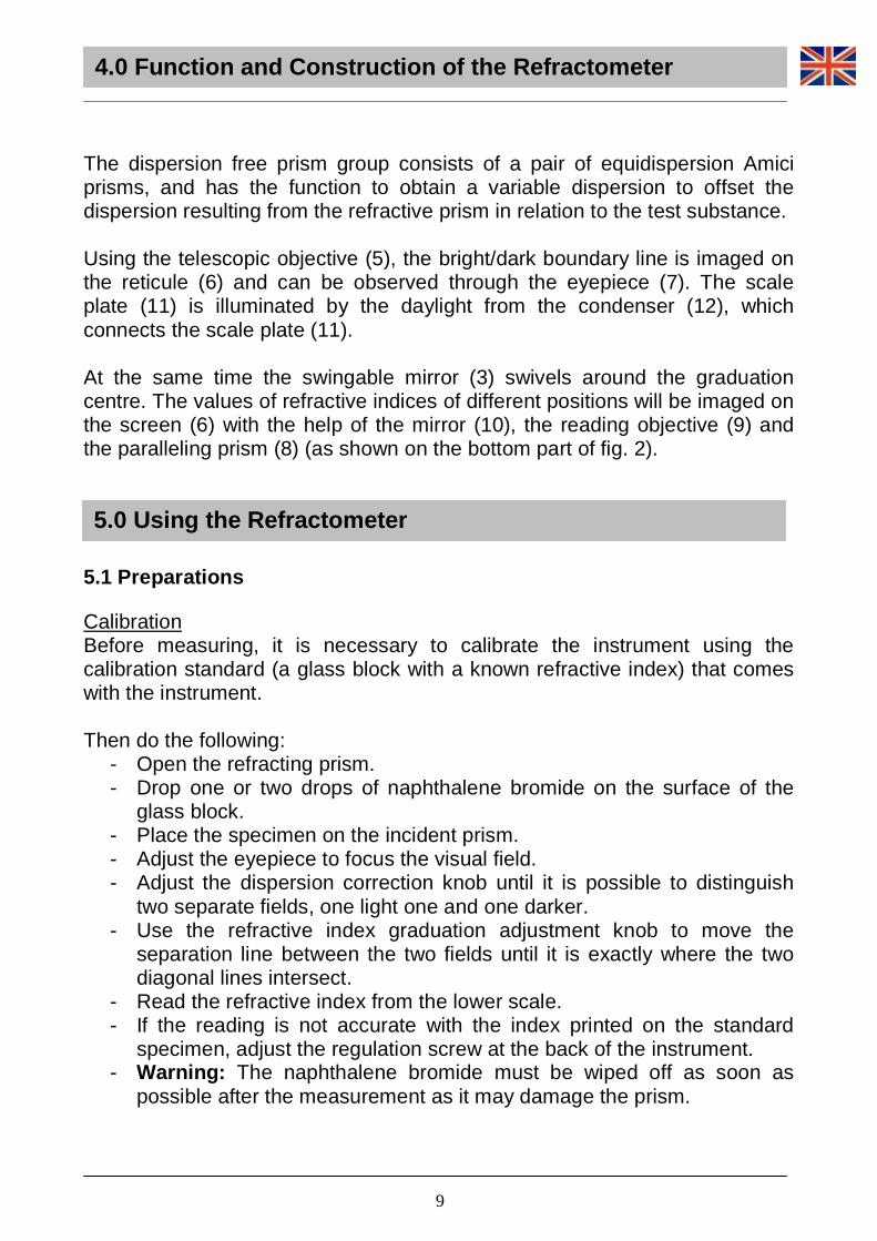
The dispersion free prism group consists of a pair of equidispersion Amici prisms, and has the function to obtain a variable dispersion to offset the dispersion resulting from the refractive prism in relation to the test substance. Using the telescopic objective (5), the bright/dark boundary line is imaged on the reticule (6) and can be observed through the eyepiece (7). The scale plate (11) is illuminated by the daylight from the condenser (12), which connects the scale plate (11). At the same time the swingable mirror (3) swivels around the graduation centre. The values of refractive indices of different positions will be imaged on the screen (6) with the help of the mirror (10), the reading objective (9) and the paralleling prism (8) (as shown on the bottom part of fig. 2). 5.1 Preparations Calibration Before measuring, it is necessary to calibrate the instrument using the calibration standard (a glass block with a known refractive index) that comes with the instrument. Then do the following:
- Open the refracting prism. - Drop one or two drops of naphthalene bromide on the surface of the
glass block. - Place the specimen on the incident prism. - Adjust the eyepiece to focus the visual field. - Adjust the dispersion correction knob until it is possible to distinguish
two separate fields, one light one and one darker. - Use the refractive index graduation adjustment knob to move the
separation line between the two fields until it is exactly where the two diagonal lines intersect.
- Read the refractive index from the lower scale. - If the reading is not accurate with the index printed on the standard
specimen, adjust the regulation screw at the back of the instrument. - Warning: The naphthalene bromide must be wiped off as soon as
possible after the measurement as it may damage the prism.
5.0 Using th e Refractometer
4.0 Function and Construction of the Refracto meter
9

2
If there is any doubt about the determined refractive index during routine testing work, the above-mentioned methods can be used for correction. Cleaning Before measuring and doing the calculation, the rough surface of the incident prism, the polished surfaces of the refracting prism and the standard specimen should be cleaned with a piece of absorbent cotton dipped with a 1:1 absolute alcohol and ether solution to remove dirt which can affect image sharpness and measuring accuracy. 5.2 Measuring Testing transparent and translucent liquid
- Drop the liquid to be tested onto the surface of the prism, then cover the incident prism and lock with the knob. Verify that the liquid layer is homogeneous, without bubbles and has been spread over the whole field of view.
- Open the shield and close the reflecting mirror. - Adjust the eyepiece to focus the visual field. - Adjust the dispersion correction knob until it is possible to distinguish
two separate fields, one light one and one darker. - Use the refractive index graduation adjustment knob to move the
separation line between the two fields until it is exactly where the two diagonal lines intersect. If needed, adjust the condenser.
- At this point, the refractive index of the tested liquid can be read from the lower scale.
Testing transparent solids To test a transparent solid object it needs to have a smooth polished surface. Open the incident prism and add one or two drops of naphthalene bromide onto the smooth plane of refracting prism, then clean the polished surface of the tested object so that it can contact better, when the work looking for the boundary line in the eyepiece can be conducted. Follow the procedure for aiming and reading as described above. Testing translucent solid One surface of the translucent solid should be a polished plane, upon which naphthalene bromide should be dropped, then put it with the naphthalene bromide side on the refracting prism. Open the reflecting mirror, adjust the angle, and use it as a surface of incidence for the measurement. Follow the operation procedure as described above.
5.0 Using the Refractometer
10
3
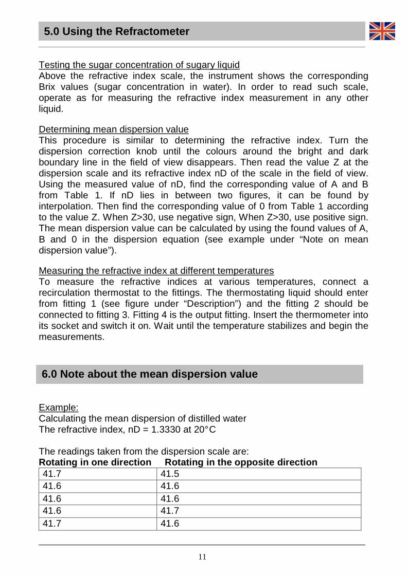
Testing the sugar concentration of sugary liquid Above the refractive index scale, the instrument shows the corresponding Brix values (sugar concentration in water). In order to read such scale, operate as for measuring the refractive index measurement in any other liquid. Determining mean dispersion value This procedure is similar to determining the refractive index. Turn the dispersion correction knob until the colours around the bright and dark boundary line in the field of view disappears. Then read the value Z at the dispersion scale and its refractive index nD of the scale in the field of view. Using the measured value of nD, find the corresponding value of A and B from Table 1. If nD lies in between two figures, it can be found by interpolation. Then find the corresponding value of 0 from Table 1 according to the value Z. When Z>30, use negative sign, When Z>30, use positive sign. The mean dispersion value can be calculated by using the found values of A, B and 0 in the dispersion equation (see example under “Note on mean dispersion value”). Measuring the refractive index at different temperatures To measure the refractive indices at various temperatures, connect a recirculation thermostat to the fittings. The thermostating liquid should enter from fitting 1 (see figure under “Description”) and the fitting 2 should be connected to fitting 3. Fitting 4 is the output fitting. Insert the thermometer into its socket and switch it on. Wait until the temperature stabilizes and begin the measurements. Example: Calculating the mean dispersion of distilled water The refractive index, nD = 1.3330 at 20° C The readings taken from the dispersion scale are: Rotating in one direction Rotating in the oppos ite direction 41.7 41.5 41.6 41.6 41.6 41.6 41.6 41.7 41.7 41.6
6.0 Note about the mean dispersion value
5.0 Using the Refractometer
11
4
The mean values are: 41.64 and 41.6 and the mean values of these give Z = 41.62 Looking in Table 1 interpolating when nD = 1.3330 we find that A=0.0248 15 and B = 0.033056 When Z = 41.62 0 = -0.5716 (because Z>30, 0 will have negative sign (-)) The mean dispersion value of distilled water can now be calculated according to the formula (see Table 1): nF - nc = A + B*0 = 0.024815 - 0.033056 x 0.5716 = 0.00592
6.0 Note about the mean dispersion value
12
5
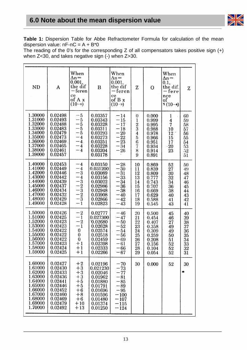
Table 1: Dispersion Table for Abbe Refractometer Formula for calculation of the mean dispersion value: nF-nC = A + B*0 The reading of the 0’s for the corresponding Z of all compensators takes positive sign (+) when Z<30, and takes negative sign (-) when Z>30.
6.0 Note about the mean dispersion value
13
6
- The following environment is required: Indoor temperature: 0-40°C, Maximum relative humidity: 85 % (non condensing) - After use, the instrument must be cleaned and stored in a dry, well-ventilated and clean place. Use the dust cover and the desiccant. - After dealing with corrosive liquid the cleaning should be done immediately after use in time to prevent from corrosive damage on the optical and mechanical parts as well as the painted surface. Warning: If left on, naphthalene bromide may corrode the prisms. - Verify that no hard contaminant is left in the sample during the test. When using a solid test sample, be sure not to scrape or damage the prism surface. - The instrument should always be kept clean. Never touch the optical parts with your fingers. Cleaning of the optical parts may be done by rubbing lightly with a piece soft lens tissue or absorbent cotton, then blow it dry with a blow drier. Only if needed, use a cloth moistened with water and a mild detergent, rinsing with water and drying immediately with a lint-free cloth. - Smears on the optical surface can be removed in time using xylene or ether. - The instrument should be protected against drastic vibration and impact to prevent the optical parts form being damaged, which will affect the testing accuracy. - Do not attempt to service the refractometer yourself. How to change the batteries of the thermometer The thermometer uses one button cell battery, LR 44. To change the battery, remove the door on the back of the thermometer, remove the old battery, replace it with a new one and replace the door. Warning: Batteries are dangerous to the environment. Discard them as required by the law.
7.0 Maintenance
14
7
If you need to send the refractometer to Optika for maintenance, please use the original packaging. The appliance reports the symbol: Such symbol means that the appliance can be a precious source of raw materials. Therefore, it must not be disposed of as waste, but separately collected for the recycling and the recovery of the materials it contained in it. Such materials, if improperly dispersed into the environment, can be harmful to the environment and to human health. The producer of the equipment, M.A.D. Apparecchiature Scientifiche – Optika Microscopes, recovers, re-uses and recycles the raw materials contained in the equipment. Such recovery, however, needs your help. When, at the end of its operating life, you shall decide to dispose of the apparatus, do not try to open it, nor to use parts of it in ways other than reported in this Manual, but bring it back to the Distributor you bought it from, or to other M.A.D. or Optika Microscopes distributors. The Distributor shall collect the apparatus free of charge. The recovery of the raw materials shall then take place in accordance with the European Directive 2002 / 96 / EC and all other relevant Directives. Never disassemble, nor dispose of as waste, apparatus reporting the “crossed bin” symbol indicated above.
8.0 Recovery and recycling
15
8
- Descrizione pag. 17
- Introduzione pag. 18
- Contenuto del kit pag. 19
- Specifiche tecniche pag. 19
- Funzionamento e struttura del rifrattometro pag. 19
- Utilizzo del rifrattometro pag. 22
- Nota sul valore di dispersione medio pag. 25
- Manutenzione pag. 27
- Misure ecologiche pag. 28
Indice
16
9
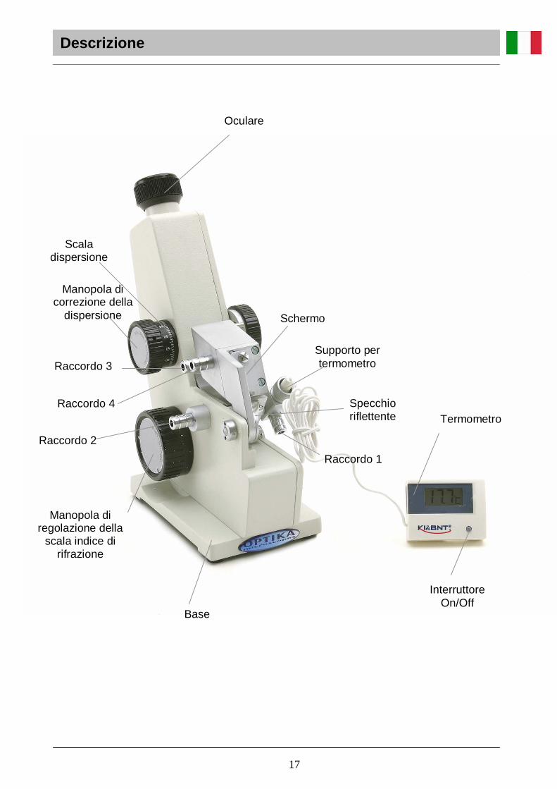
Descrizione
Specchio riflettente
Manopola di correzione della
dispersione
Oculare
Interruttore On/Off
Termometro
Base
Supporto per termometro
Manopola di regolazione della
scala indice di rifrazione
Schermo
Raccordo 1
Raccordo 2
Raccordo 4
Raccordo 3
Scala dispersione
17

10
Descri zion e
Manopola di bloccaggio
Prisma incidente
Prisma rifrangente
Involucro
Condensatore
18
11
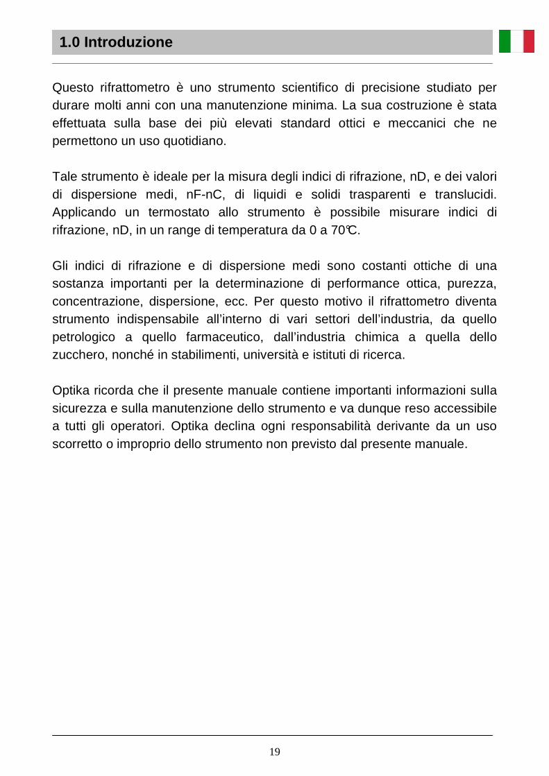
Questo rifrattometro è uno strumento scientifico di precisione studiato per durare molti anni con una manutenzione minima. La sua costruzione è stata effettuata sulla base dei più elevati standard ottici e meccanici che ne permettono un uso quotidiano. Tale strumento è ideale per la misura degli indici di rifrazione, nD, e dei valori di dispersione medi, nF-nC, di liquidi e solidi trasparenti e translucidi. Applicando un termostato allo strumento è possibile misurare indici di rifrazione, nD, in un range di temperatura da 0 a 70°C. Gli indici di rifrazione e di dispersione medi sono costanti ottiche di una sostanza importanti per la determinazione di performance ottica, purezza, concentrazione, dispersione, ecc. Per questo motivo il rifrattometro diventa strumento indispensabile all’interno di vari settori dell’industria, da quello petrologico a quello farmaceutico, dall’industria chimica a quella dello zucchero, nonché in stabilimenti, università e istituti di ricerca. Optika ricorda che il presente manuale contiene importanti informazioni sulla sicurezza e sulla manutenzione dello strumento e va dunque reso accessibile a tutti gli operatori. Optika declina ogni responsabilità derivante da un uso scorretto o improprio dello strumento non previsto dal presente manuale.
1.0 Introduzione
19
12
Rifrattometro di Abbe (con custodia di plastica) 1 pz Termometro speciale (con pila a bottone LR 44) 1 conf. Campione standard per taratura 1 pz Bromuro di naftalene 1 flacone Cacciavite 1 pz Manuale d’istruzioni 1 copia Certificazione del prodotto 1 copia
Campo di misura di nD 1.300-1.700 Precisione della misura di nD ± 0.0002 Ingrandimento sistema telescopico 2x Ingrandimento sistema di lettura 30x Peso dello strumento 2,2 kg Dimensioni dello strumento 100 x 200 x 240 mm
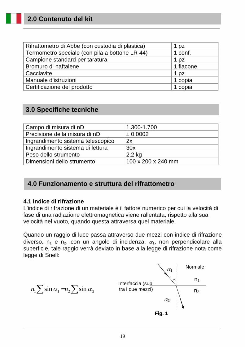
4.1 Indice di rifrazione L’indice di rifrazione di un materiale è il fattore numerico per cui la velocità di fase di una radiazione elettromagnetica viene rallentata, rispetto alla sua velocità nel vuoto, quando questa attraversa quel materiale. Quando un raggio di luce passa attraverso due mezzi con indice di rifrazione diverso, n1 e n2, con un angolo di incidenza, α1, non perpendicolare alla superficie, tale raggio verrà deviato in base alla legge di rifrazione nota come legge di Snell:
2.0 Contenuto del kit
3.0 Specifiche tecniche
4.0 Funzionamento e struttura del rifrattometro
α1
Interfaccia (sup. tra i due mezzi)
α2
n1
n2
Fig. 1
∑∑ = 2211 sinsin αα nn
Normale
19
13
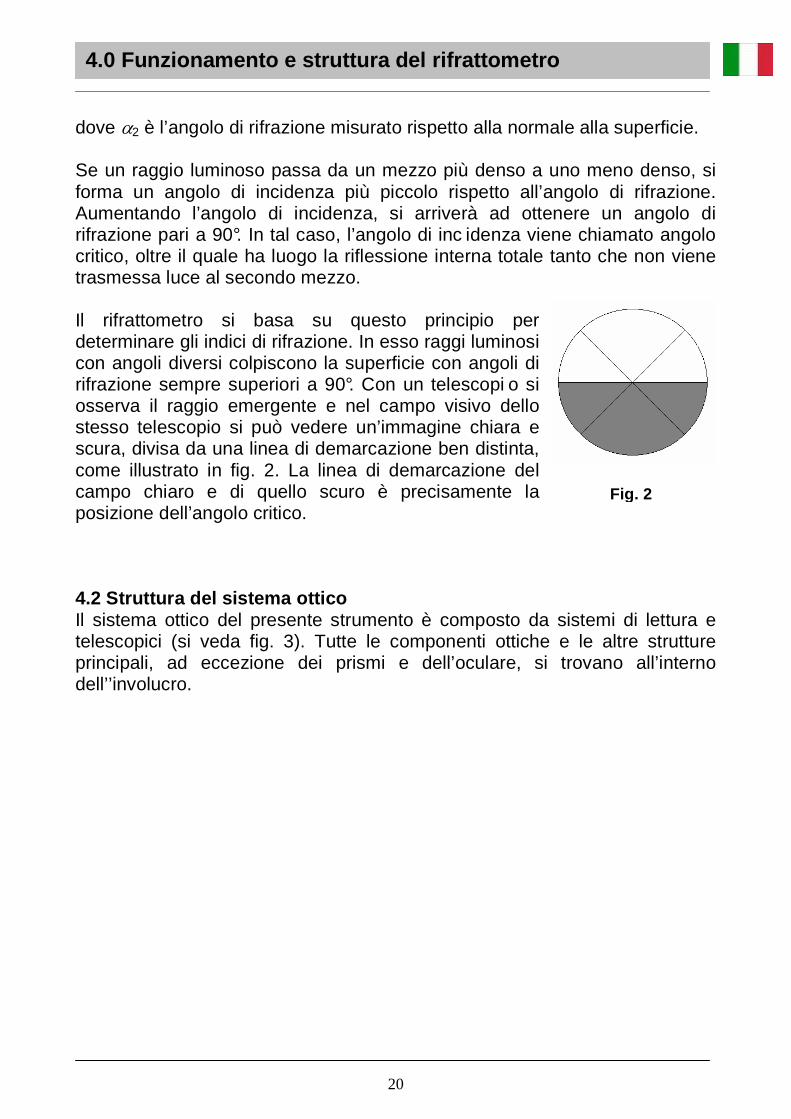
dove α2 è l’angolo di rifrazione misurato rispetto alla normale alla superficie. Se un raggio luminoso passa da un mezzo più denso a uno meno denso, si forma un angolo di incidenza più piccolo rispetto all’angolo di rifrazione. Aumentando l’angolo di incidenza, si arriverà ad ottenere un angolo di rifrazione pari a 90°. In tal caso, l’angolo di inc idenza viene chiamato angolo critico, oltre il quale ha luogo la riflessione interna totale tanto che non viene trasmessa luce al secondo mezzo. Il rifrattometro si basa su questo principio per determinare gli indici di rifrazione. In esso raggi luminosi con angoli diversi colpiscono la superficie con angoli di rifrazione sempre superiori a 90°. Con un telescopi o si osserva il raggio emergente e nel campo visivo dello stesso telescopio si può vedere un’immagine chiara e scura, divisa da una linea di demarcazione ben distinta, come illustrato in fig. 2. La linea di demarcazione del campo chiaro e di quello scuro è precisamente la posizione dell’angolo critico. 4.2 Struttura del sistema ottico Il sistema ottico del presente strumento è composto da sistemi di lettura e telescopici (si veda fig. 3). Tutte le componenti ottiche e le altre strutture principali, ad eccezione dei prismi e dell’oculare, si trovano all’interno dell’’involucro.
Fig. 2
4.0 Funzionamento e struttura del rifrattome tro
20
14
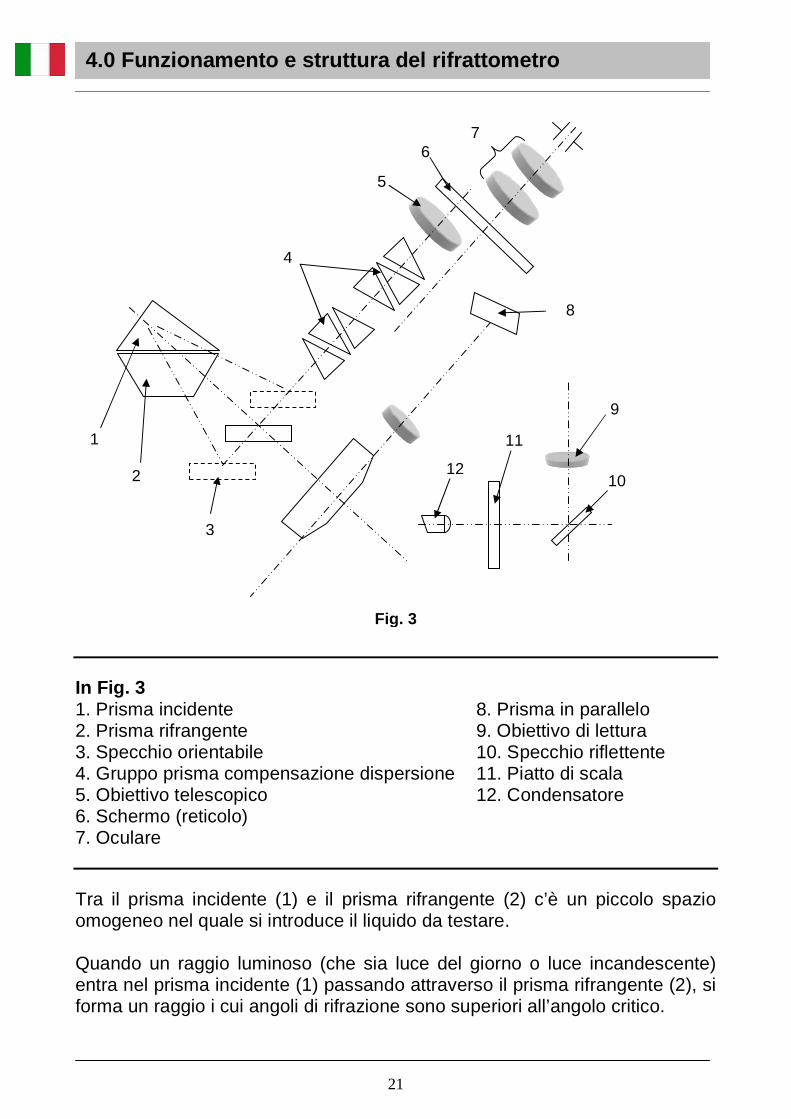
In Fig. 3 1. Prisma incidente 2. Prisma rifrangente 3. Specchio orientabile 4. Gruppo prisma compensazione dispersione 5. Obiettivo telescopico 6. Schermo (reticolo) 7. Oculare
8. Prisma in parallelo 9. Obiettivo di lettura 10. Specchio riflettente 11. Piatto di scala 12. Condensatore
Tra il prisma incidente (1) e il prisma rifrangente (2) c’è un piccolo spazio omogeneo nel quale si introduce il liquido da testare. Quando un raggio luminoso (che sia luce del giorno o luce incandescente) entra nel prisma incidente (1) passando attraverso il prisma rifrangente (2), si forma un raggio i cui angoli di rifrazione sono superiori all’angolo critico.
1
7
2
4
5
8
6
10
9
3
11
12
Fig. 3
4.0 Funzionamento e struttura del rifrattometro
21

Tale raggio entrerà nello strumento attraverso lo specchio orientabile (3) e attraverserà il gruppo prisma privo di dispersione (4). Il gruppo prisma privo di dispersione è costituito da una coppia di prismi Amici ad equidispersione con la funzione di ottenere una dispersione variabile per controbilanciare la dispersione risultante dal prisma rifrangente rispetto alla sostanza in esame. Con l’obiettivo telescopico (5), la linea di demarcazione chiaro/scuro viene riflessa sul reticolo (6) e può essere vista attraverso l’oculare (7). Il piatto di scala (11) viene illuminato dal condensatore (12), ad esso collegato, sfruttando la luce solare. Nel frattempo lo specchio orientabile (3) ruota attorno al centro della scala graduata e sullo schermo (6) vengono riflessi i valori degli indici di rifrazione delle varie posizioni con l’aiuto dello specchio (10), dell’obiettivo di lettura (9) e del prisma montato in parallelo (8) (si veda la parte bassa della fig. 2). 5.1 Preparazione Taratura Prima della misurazione è necessario tarare lo strumento con il campione standard di taratura fornito in dotazione insieme allo strumento (si tratta di un blocco di vetro con indice di rifrazione noto). Procedere come segue:
- Aprire il prisma rifrangente. - Lasciar cadere una o due gocce di bromuro di naftalene sulla superficie
del blocco di vetro. - Mettere il campione sul prisma incidente. - Regolare l’oculare per mettere a fuoco il campo visivo. - Regolare la correzione della dispersione con l’apposita manopola fino a
vedere due campi separati, uno chiaro e uno più scuro. - Con la manopola di regolazione della scala dell’indice di rifrazione
spostare la linea di separazione tra i campi fino al punto esatto di intersezione delle due linee diagonali.
- Leggere l’indice di rifrazione sulla scala più bassa. - Se la lettura dell’indice non è uguale a quello indicato sul campione
standard, agire sulla vite di regolazione posta sul retro dello strumento.
5.0 Utilizz o del rifrattometro
4.0 Funzionamento e struttura del rifrattometro
22

- Attenzione: Immediatamente dopo la misurazione, eliminare il bromuro di naftalene dal prisma per evitare eventuali danni a quest’ultimo.
Nel caso di dubbi sull’indice di rifrazione determinato durante misurazioni di routine, si può applicare il metodo indicato per procedere ad una correzione. Pulizia Prima di ogni misurazione e calcolo, pulire con del cotone idrofilo bagnato con una soluzione 1:1 di alcol assoluto e etere la superficie ruvida del prisma incidente e le superfici lucide del prisma rifrangente e del campione standard per rimuovere eventuali tracce di sporco che possano ridurre la nitidezza dell’immagine e la precisione della misurazione. 5.2 Misurazione Esame di liquidi trasparenti e translucidi
- Versare il liquido da testare sulla superficie del prisma, quindi coprire il prisma incidente e chiudere con l’apposita manopola. Controllare che lo strato di liquido sia omogeneo, privo di bolle, e che ricopra l’intero campo visivo.
- Aprire lo schermo e chiudere lo specchio riflettente. - Regolare l’oculare per mettere a fuoco il campo visivo. - Regolare la correzione della dispersione con l’apposita manopola fino a
vedere due campi separati, uno chiaro e uno più scuro. - Con la manopola di regolazione della scala dell’indice di rifrazione
spostare la linea di separazione tra i campi fino al punto esatto di intersezione delle due linee diagonali. Se necessario, sistemare il condensatore.
- A questo punto è possibile leggere l’indice di rifrazione del liquido in esame sulla scala in basso.
Esame di solidi trasparenti Per poter testare un oggetto solido trasparente, è necessario che esso abbia una superficie liscia lucida. Aprire il prisma incidente e versare una o due gocce di bromuro di naftalene sulla superficie liscia del prisma rifrangente, quindi pulire la superficie lucida dell’oggetto da testare in modo che il contatto sia migliore al momento dell’identificazione della linea di demarcazione attraverso l’oculare. Per la messa a fuoco e la lettura del valore, si segua la stessa procedura sopra descritta.
5.0 Utilizzo del rifrattometro
9
23

Esame di solidi translucidi Una superficie del solido translucido deve essere piana e lucida. Versare su di essa del bromuro di naftalene, quindi mettere tale superficie a contatto con il prisma rifrangente. Aprire lo specchio riflettente, sistemare l’angolo e utilizzarlo come superficie di incidenza per la misura. A questo punto seguire le procedure sopra descritte. Esame della concentrazione di zuccheri in liquidi zuccherini Al di sopra della scala dell’indice di rifrazione, lo strumento indica anche i corrispondenti valori Brix (ovvero concentrazione dello zucchero in acqua). Per leggere la scala Brix, è sufficiente operare come per la misura dell’indice di rifrazione in qualsiasi altro liquido. Determinazione del valore di dispersione medio Tale procedura è simile alla determinazione dell’indice di rifrazione. Ruotare la manopola di correzione della dispersione finché non spariscono i colori intorno alla linea di demarcazione chiaro/scuro nel campo visivo, quindi leggere il valore Z sulla scala di dispersione e l’indice di rifrazione nD sulla scala presente nel campo visivo. Con il valore misurato di nD, trovare i corrispondenti valori di A e B nella tabella 1. Se nD è un valore intermedio, è possibile applicare l’interpolazione. Cercare quindi il valore corrispondente di 0 nella tabella 1 in base al valore Z. Se Z > 30, si usi il segno “ - ”. Se Z > 30, si usi il segno “ + ”. Per calcolare il valore di dispersione medio si possono sostituire i valori di A, B e 0 che si sono trovati nell’equazione di dispersione (si veda l’esempio in “Nota sul valore di dispersione medio”). Misura dell’indice di rifrazione a varie temperature Per misurare l’indice di rifrazione a varie temperature, collegare un termostato a ricircolazione ai raccordi. Il liquido del termostato deve entrare nel raccordo 1 (si veda la figura in “Descrizione”), il raccordo 2 va collegato al 3, mentre il 4 è quello d’uscita. Inserire il termometro nel suo supporto e accenderlo. Attendere la stabilizzazione della temperatura e dare il via alle misurazioni.
5.0 Utilizzo del rifrattometro
24
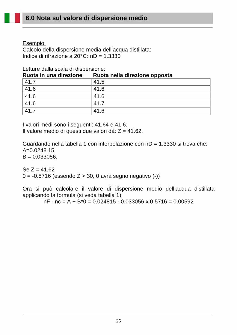
Esempio: Calcolo della dispersione media dell’acqua distillata: Indice di rifrazione a 20° C: nD = 1.3330 Letture dalla scala di dispersione: Ruota in una direzione Ruota nella direzione op posta 41.7 41.5 41.6 41.6 41.6 41.6 41.6 41.7 41.7 41.6
I valori medi sono i seguenti: 41.64 e 41.6. Il valore medio di questi due valori dà: Z = 41.62. Guardando nella tabella 1 con interpolazione con nD = 1.3330 si trova che: A=0.0248 15 B = 0.033056. Se Z = 41.62 0 = -0.5716 (essendo Z > 30, 0 avrà segno negativo (-)) Ora si può calcolare il valore di dispersione medio dell’acqua distillata applicando la formula (si veda tabella 1):
nF - nc = A + B*0 = 0.024815 - 0.033056 x 0.5716 = 0.00592
6.0 Nota sul valore di dispersione medio
25

Tabella 1: Tavola dei valori di dispersione per rifrattometro di Abbe. Formula per il calcolo del valore di dispersione medio: nF-nC = A + B*0. La lettura degli 0 dei corrispondenti valori di Z di tutti i compensatori assume segno positivo (+) con Z<30, e segno negativo (-) con Z>30.
6.0 Nota sul valore di dispersione medio
Con ∆n = 0.001, la diffe-renza di A x (10-6)
Con ∆n = 0.001, la diffe-renza di B x (10-
9)
Con ∆n = 0.1, la diffe-renza di x (10-4)
26

- Ambiente d’esercizio: Temperatura interna: 0-40°C , Umidità relativa massima: 85 % (in assenza di condensa) - Dopo l’uso pulire lo strumento e conservarlo in luogo asciutto, ventilato e pulito. Coprirlo con l’apposita custodia antipolvere e usare l’essiccante. - Nel caso di utilizzo di liquidi corrosivi, pulire immediatamente dopo l’uso per evitare la corrosione di parti ottiche e meccaniche così come della superficie verniciata. Attenzione: Il bromuro di naftalene può corrodere i prismi se non rimosso. - Controllare che durante il test non rimanga nessuna sostanza fortemente contaminante nel campione. Nel caso di campioni solidi, assicurarsi di non graffiare o danneggiare la superficie del prisma. - Tenere sempre pulito lo strumento. Non toccare le parti ottiche con le dita. Per pulire le parti ottiche strofinare leggermente con un apposito panno soffice o cotone idrofilo, quindi asciugare con un generatore d’aria. Se necessario, usare un panno inumidito con acqua e detergente neutro, quindi sciacquare con acqua e asciugare immediatamente con un panno non sfilacciato. - Per rimuovere eventuali macchie dalla superficie ottica usare xilene o etere. - Proteggere lo strumento da forti vibrazioni e urti per evitare che le parti ottiche si danneggino, il che influirebbe negativamente sulla precisione delle misurazioni.
- Non provvedere da soli alla riparazione del rifrattometro. Sostituzione delle pile del termometro Il termometro funziona con una pila a bottone LR 44. Per sostituirla, togliere la porticina sul retro del termometro, estrarre la pila vecchia e inserirne una nuova. Richiudere la porticina. Attenzione: Le pile sono fortemente inquinanti. Non disperdere nell’ambiente. Si prega di utilizzare l’imballaggio originale nel caso in cui fosse necessario rispedire il microscopio alla ditta Optika per la riparazione.
7.0 Manutenzione
27

Sull’apparecchio è applicato il seguente simbolo: Tale simbolo indica che l’apparecchio può essere fonte di preziose materie prime, e che quindi non deve essere gettato nei rifiuti, ma raccolto separatamente ed avviato al recupero e al riciclaggio. Queste materie prime, se disperse nell’ambiente, possono causare danni all’ambiente e alla salute dei cittadini. Il produttore dell’apparecchio, M.A.D. Apparecchiature Scientifiche – Optika Microscopes si fa carico di tutelare l’ambiente recuperando, riutilizzando e riciclando le materie prime contenute nell’apparecchio. Tale recupero richiede tuttavia il Vostro contributo. Quando, al termine del suo utilizzo, l’apparecchio dovrà essere eliminato, non tentate di aprirlo, di riutilizzarne parti in modo diverso da quanto descritto nella presente Guida Utente, e non gettate l’apparecchio nei rifiuti, ma riportatelo al rivenditore dal quale l’avete acquistato, o ad un altro rivenditore di apparecchiature M.A.D. o Optika Microscopes. Il rivenditore ritirerà gratuitamente l’apparecchio. Il recupero delle materie prime avverrà quindi secondo la direttiva europea 2002 / 96 / CE, i suoi aggiornamenti e ogni altra Direttiva in vigore. Attenzione: la Legge prevede sanzioni per chi smaltisce abusivamente apparecchiature riportanti il simbolo sopraindicato. M.A.D. Apparecchiature Scientifiche – Optika Microscopes declina ogni responsabilità verso chi smaltisce o modifica l’apparecchio in modo difforme da quanto qui precisato.
8.0 Misure ecologiche
28

www.optikamicroscopes.com [email protected]
MAD Apparecchiature scientifiche
Via Rigla 32, Ponteranica (BG) - ITALY Tel.: ++39 035 571392 (6 linee) Telefax: ++ 39 035 571435
M.A.D. Iberica Aparatos Cientificos
c/. Puig i Pidemunt, nº 28 1º 2ª - (Pol. Ind. Plà d’en Boet) 08302 MATARO (Barcelona) España Tel: +34 937.586.245 Fax: +34 937.414.529
Optika mikroscop ve laboratuvar cihazlari ticaret l td. Şti.
Yürekli Adam Sokak N0:20 Kat:6 Daire:14 Kavacık BEYKOZ/İSTANBUL Tel: 090 216 413 4100 Fax: 090 216 413 1617
Alpha Optika Microscopes Hungary
2030 ÉRD, Kaktusz u. 22.- HUNGARY Tel.: (23) 520-077 Fax: (23) 374-965