instruction manual - ge grid solutions · table of contents multinet4 multi-port serial server...
TRANSCRIPT

GE Multilin
215 Anderson Avenue, Markham, Ontario, Canada L6E 1B3
Tel: (905) 294-6222, 1-800-547-8629 (North America)Fax: (905) 201-2098
Internet: http://www.GEmultilin.com
Manual P/N: 1601-9075-A1 (GEK-113502)
Copyright © 2008 GE Multilin
Digital EnergyMultilin
*1601-9075-A1*
GE Multilin's Quality Management System is registered to
ISO9001:2000
QMI # 005094UL # A3775
Multinet4 Multi-Port Serial Server & Managed SwitchInstruction Manual

© 2008 GE Multilin Incorporated. All rights reserved.
GE Multilin Multinet4 Serial Port Server & Managed Switch instruction manual.
Multinet4 Serial Port Server & Managed Switch, is a registered trademark of GE Multilin Inc.
The contents of this manual are the property of GE Multilin Inc. This documentation is furnished on license and may not be reproduced in whole or in part without the permission of GE Multilin. The content of this manual is for informational use only and is subject to change without notice.
Part numbers contained in this manual are subject to change without notice, and should therefore be verified by GE Multilin before ordering.
Part number: 1601-9075-A1 (September 2008)

TABLE OF CONTENTS
MULTINET4 MULTI-PORT SERIAL SERVER & MANAGED SWITCH – INSTRUCTION MANUAL TOC–1
Table of Contents
1: OVERVIEW CONFIGURATION ............................................................................................................................. 1-1CONNECTIVITY ...................................................................................................................... 1-1POWER AND GROUND ........................................................................................................ 1-2INDICATORS .......................................................................................................................... 1-2MOUNTING OPTIONS .......................................................................................................... 1-3
SPECIFICATIONS ............................................................................................................................... 1-4PHYSICAL .............................................................................................................................. 1-4ENVIRONMENTAL ................................................................................................................. 1-4TYPE TESTS ........................................................................................................................... 1-4POWER REQUIREMENTS ...................................................................................................... 1-6PORTS AND EXTERNAL CONNECTORS .............................................................................. 1-7INDICATORS .......................................................................................................................... 1-7
PINOUTS .............................................................................................................................................. 1-9RJ45 ..................................................................................................................................... 1-9FIBER OPTIC ......................................................................................................................... 1-9DB9 (FEMALE) – CONSOLE PORT ..................................................................................... 1-10PHOENIX CONNECTOR – ALARM PORT ............................................................................ 1-10PHOENIX CONNECTORS – SERIAL PORTS ........................................................................ 1-11
FEATURES AND BENEFITS ............................................................................................................ 1-12MULTINET4 MULTI-PORT SERIAL SERVER & MANAGED SWITCH ................................ 1-12FEATURES SUMMARY .......................................................................................................... 1-13
2: GETTING STARTED INSTALLATION ................................................................................................................................... 2-1TOOLS ................................................................................................................................... 2-1SITE SUITABILITY .................................................................................................................. 2-1WIRING AND GROUNDING GUIDELINES ........................................................................... 2-2FIBER OPTIC SAFETY ........................................................................................................... 2-2FIBER OPTIC HANDLING ..................................................................................................... 2-3EXTERNAL CONNECTIONS .................................................................................................. 2-3
UNPACKING ....................................................................................................................................... 2-4INSTALLATION OF THE MULTINET4 UNIT .............................................................................. 2-5
MOUNTING ........................................................................................................................... 2-5Mounting Hardware .................................................................................................2 - 5Mounting in a 19” Rail System - General ........................................................2 - 5Mounting in a 19” Rail System - Conventional Mounting .......................2 - 6Mounting in a 19” Rail System - Reverse Mounting ..................................2 - 7Mounting on a Panel ................................................................................................2 - 8Mounting in a DIN Rail System ............................................................................2 - 10
CONNECTING FACILITY POWER ......................................................................................... 2-11Making the Ground and Power Connections ...............................................2 - 11
CONNECTING TO THE CONSOLE PORT AND THE ALARM PORT .................................... 2-13Console Port .................................................................................................................2 - 13Alarm Port .....................................................................................................................2 - 13
CONNECTING NETWORK CABLES ...................................................................................... 2-13Connecting Serial Cables .......................................................................................2 - 13Connecting RJ45 Twisted Pair .............................................................................2 - 14Connecting ST-type Fiber Optics (twist-lock) ................................................2 - 14Connecting SC-type or LC-type Fiber Optics (snap-in) .............................2 - 15

TOC–2 MULTINET4 MULTI-PORT SERIAL SERVER & MANAGED SWITCH – INSTRUCTION MANUAL
TABLE OF CONTENTS
Connecting Single-mode Fiber Optics .............................................................2 - 15MAINTENANCE .................................................................................................................................. 2-16
REMOVING THE MULTINET4 ............................................................................................... 2-16Disconnecting Power and Ground Lines ........................................................2 - 16Disconnecting Network Cables ...........................................................................2 - 16Packing the Multinet4 for Shipment .................................................................2 - 17
CLEANING FIBER OPTIC DEVICES ...................................................................................... 2-17Cleaning Connectors ................................................................................................2 - 17Cleaning Optical Ports .............................................................................................2 - 18
SOFTWARE MANAGEMENT .......................................................................................................... 2-19CONFIGURING A NEW IP ADDRESS .................................................................................. 2-19
THE ENERVISTA MULTINET4 SETUP SOFTWARE OVERVIEW ......................................... 2-22THE ADVANCED SETTING - ADMINISTRATOR INTERFACE OVERVIEW ...................... 2-23
LOGGING IN FOR THE FIRST TIME ..................................................................................... 2-23ADMINISTRATOR INTERFACE OVERVIEW ........................................................................... 2-25THE ADMINISTRATOR INTERFACE NAVIGATION TREE ..................................................... 2-28
3: ENERVISTA MULTINET4 SETUP SOFTWARE
PC REQUIREMENTS ......................................................................................................................... 3-1INSTALLATION .................................................................................................................................. 3-2CONFIGURING ETHERNET COMMUNICATION ..................................................................... 3-3USING THE QUICK CONNECT FEATURE ................................................................................. 3-6CONNECTING TO THE MULTINET4 ........................................................................................... 3-7PORT SETTING ................................................................................................................................... 3-8ADVANCED SETTING ....................................................................................................................... 3-10FIRMWARE UPGRADE .................................................................................................................... 3-11OFF-LINE FEATURE .......................................................................................................................... 3-12
READING DEVICE SETTINGS ............................................................................................... 3-12WRITING SETTINGS TO A DEVICE ...................................................................................... 3-13
CONFIGURE A NEW IP ADDRESS THROUGH CONSOLE PORT ...................................... 3-14
4: SYSTEM ADMINISTRATION
VIRTUAL FRONT PANEL ................................................................................................................. 4-1ADMINISTRATION TASKS .............................................................................................................. 4-2
SYSTEM ................................................................................................................................. 4-2SYSTEM INFORMATION ........................................................................................................ 4-2SYSTEM STATUS ................................................................................................................... 4-3TIME ....................................................................................................................................... 4-4
Time: Time and Date ................................................................................................4 - 4Time: Zone and DST ..................................................................................................4 - 5Time: Persistence .......................................................................................................4 - 6
SNTP .................................................................................................................................... 4-7SNTP: Global Settings ...............................................................................................4 - 7SNTP: Servers ...............................................................................................................4 - 8
SNMP ................................................................................................................................... 4-9SNMP: Global Settings .............................................................................................4 - 9SNMP: Management Stations ..............................................................................4 - 11SNMP: Trap Stations .................................................................................................4 - 12SNMP: Users .................................................................................................................4 - 13SNMP: Statistics ..........................................................................................................4 - 15
AUTHENTICATION ................................................................................................................. 4-19Authentication: Policies ..........................................................................................4 - 19Authentication: Accounts ......................................................................................4 - 22Authentication: Files .................................................................................................4 - 24
SESSIONS .............................................................................................................................. 4-25Sessions: Policies .......................................................................................................4 - 25

TABLE OF CONTENTS
MULTINET4 MULTI-PORT SERIAL SERVER & MANAGED SWITCH – INSTRUCTION MANUAL TOC–3
Sessions: Active Logins ...........................................................................................4 - 25CHANGE PASSWORD ........................................................................................................... 4-26SOFTWARE UPGRADE ......................................................................................................... 4-27CONFIGURATION .................................................................................................................. 4-31
Configuration: Files ...................................................................................................4 - 31Configuration: Defaults ...........................................................................................4 - 32
SYSTEM REBOOT .................................................................................................................. 4-34EVENTS TASKS ................................................................................................................................... 4-35
LOGS ..................................................................................................................................... 4-35Logs: Global Settings ................................................................................................4 - 40Logs: Files ......................................................................................................................4 - 41
SYSLOG ................................................................................................................................. 4-42Syslog: Global Settings ............................................................................................4 - 43Syslog: Collectors .......................................................................................................4 - 43
ETHERNET TASKS ............................................................................................................................. 4-45PORTS .................................................................................................................................... 4-45
Ports: Settings .............................................................................................................4 - 45Ports: Status .................................................................................................................4 - 48Ports: Summary Statistics ......................................................................................4 - 49Ports: Extended Statistics ......................................................................................4 - 50Ports: Mirroring ...........................................................................................................4 - 54Ports: Rate Limits .......................................................................................................4 - 55
BRIDGE .................................................................................................................................. 4-56Bridge: Global Settings ............................................................................................4 - 57Bridge: Static MACs ...................................................................................................4 - 57Bridge: Station Cache ..............................................................................................4 - 59
RSTP ..................................................................................................................................... 4-60RSTP: Bridge Settings ...............................................................................................4 - 60RSTP: Port Settings ....................................................................................................4 - 62RSTP: Bridge Status ...................................................................................................4 - 63RSTP: Port Status ........................................................................................................4 - 64
VLAN .................................................................................................................................... 4-65VLAN: Global Settings ..............................................................................................4 - 65VLAN: VIDs .....................................................................................................................4 - 66VLAN: Port Settings ...................................................................................................4 - 67
SERIAL TASKS .................................................................................................................................... 4-70PORTS .................................................................................................................................... 4-70
Ports: Profiles ...............................................................................................................4 - 70Ports: Settings .............................................................................................................4 - 74Ports: Statistics ...........................................................................................................4 - 75
TERMINAL SERVER ............................................................................................................... 4-76Terminal Server: Channel Settings ....................................................................4 - 76Terminal Server: Channel Status ........................................................................4 - 80Terminal Server: Connections ..............................................................................4 - 81
MODBUS ............................................................................................................................... 4-82Global Settings ............................................................................................................4 - 82Fixed Mappings ..........................................................................................................4 - 83Modbus: Local Masters ...........................................................................................4 - 84Modbus: Local Slaves ..............................................................................................4 - 85Modbus: Remote Slaves .........................................................................................4 - 86Modbus: Connections ..............................................................................................4 - 88
IP TASKS ............................................................................................................................................... 4-89SETTINGS .............................................................................................................................. 4-89ARP TABLE ........................................................................................................................... 4-89
QOS TASKS .......................................................................................................................................... 4-91DiffServ ...........................................................................................................................4 - 91802.1p .............................................................................................................................4 - 92

TOC–4 MULTINET4 MULTI-PORT SERIAL SERVER & MANAGED SWITCH – INSTRUCTION MANUAL
TABLE OF CONTENTS
Ethernet Port ................................................................................................................4 - 93IP Flows ..........................................................................................................................4 - 94
SECURITY TASKS ............................................................................................................................... 4-96CERTIFICATES ....................................................................................................................... 4-96
Certificates: Local ......................................................................................................4 - 96Certificates: Trusted ..................................................................................................4 - 97
ETHERNET PORT .................................................................................................................. 4-98SERIAL/SSL .......................................................................................................................... 4-99WEB SERVER ........................................................................................................................ 4-101CLI ......................................................................................................................................... 4-102RADIUS ............................................................................................................................... 4-103
RADIUS: Global Settings ..........................................................................................4 - 103RADIUS: Servers ..........................................................................................................4 - 104
WIZARDS .............................................................................................................................................. 4-106THE CERTIFICATE CREATION WIZARD .............................................................................. 4-106
5: THE CLI AND PROTOCOL MONITOR
CLI ACCESS ......................................................................................................................................... 5-1MULTINET4 SUPPORT FOR SFTP ...................................................................................... 5-2
CLI FUNCTIONALITY ........................................................................................................................ 5-4GLOBAL COMMANDS .......................................................................................................... 5-4BASIC AND SPECIFIC COMMANDS ..................................................................................... 5-5
The bridge Command ..............................................................................................5 - 6The config Command ..............................................................................................5 - 7The Ethernet Command .........................................................................................5 - 8The ip Command .......................................................................................................5 - 9The log Command .....................................................................................................5 - 10The monitor Command ...........................................................................................5 - 11Protocol Monitor Output Example .....................................................................5 - 14The ping Command ..................................................................................................5 - 15The rstp Command ...................................................................................................5 - 15The session Command ............................................................................................5 - 17The ssh Command ....................................................................................................5 - 18The sw command ......................................................................................................5 - 19The system Command ............................................................................................5 - 23The terminal Command ..........................................................................................5 - 23The vlan Command ..................................................................................................5 - 24The web Command ..................................................................................................5 - 25
6: OPERATIONAL GUIDE QUALITY OF SERVICE ...................................................................................................................... 6-1QOS MODEL ........................................................................................................................ 6-1PRIORITY QUEUES ................................................................................................................ 6-2DIFFSERV MARKING ............................................................................................................ 6-2
DiffServ Processing ...................................................................................................6 - 3DiffServ-to-802.1p Mapping .................................................................................6 - 3802.1p-to-priority queue Mapping ....................................................................6 - 3
SNMP ..................................................................................................................................................... 6-4SUPPORTED VERSIONS AND FEATURES ............................................................................ 6-4
RSTP ....................................................................................................................................................... 6-5RSTP SETUP ........................................................................................................................ 6-5
BPDUs .............................................................................................................................6 - 6Bridge Roles .................................................................................................................6 - 6Port Roles ......................................................................................................................6 - 6Edge Ports and Point-to-Point Links .................................................................6 - 7Port States .....................................................................................................................6 - 7
RSTP NORMAL OPERATION .............................................................................................. 6-8

TABLE OF CONTENTS
MULTINET4 MULTI-PORT SERIAL SERVER & MANAGED SWITCH – INSTRUCTION MANUAL TOC–5
DESIGN CONSIDERATIONS ................................................................................................. 6-8Configuring Bridge Settings ..................................................................................6 - 8Configuring Port Settings .......................................................................................6 - 9
VLAN ...................................................................................................................................................... 6-10ADDING VLANS .................................................................................................................. 6-10
VLAN IDs ........................................................................................................................6 - 10CONFIGURING PORTS FOR VLAN MEMBERSHIP ............................................................ 6-10
Port VLAN IDs ..............................................................................................................6 - 10Tagging ..........................................................................................................................6 - 10Filtering ...........................................................................................................................6 - 11Frame Classification and Forwarding ..............................................................6 - 11
VLANS AND SERIAL PORTS ............................................................................................... 6-12SECURITY ............................................................................................................................................. 6-13
ETHERNET PORT SECURITY ................................................................................................ 6-13Address Locking .........................................................................................................6 - 13Link Locking ..................................................................................................................6 - 13
SERIAL PORT SECURITY ...................................................................................................... 6-13Serial Data Over SSL ................................................................................................6 - 13Multinet4 SSL Version Support ............................................................................6 - 14Secure Web Server using HTTP over SSL (https://) .....................................6 - 14
KEYS AND CERTIFICATES .................................................................................................... 6-14RSA Public Key Cryptography ..............................................................................6 - 15Digital Signatures ......................................................................................................6 - 15X.509 Certificates .......................................................................................................6 - 15Certificate Authority .................................................................................................6 - 15Multinet4 Certificate Files ......................................................................................6 - 15Multinet4 Key Files ....................................................................................................6 - 16Key Exchange ..............................................................................................................6 - 18Peer Authentication ..................................................................................................6 - 18Certificate and Key File Generation ..................................................................6 - 18Certificate and Key File Installation ..................................................................6 - 21
RADIUS SUPPORT .............................................................................................................. 6-21MULTINET4 CIPHER SUPPORT ........................................................................................... 6-21
SSH ......................................................................................................................................................... 6-23MODBUS .............................................................................................................................................. 6-24
NETWORK TOPOLOGIES ...................................................................................................... 6-24SERIAL PROTOCOL VARIANTS ............................................................................................ 6-24NETWORK PROTOCOL ......................................................................................................... 6-25EXCEPTION HANDLING ....................................................................................................... 6-25TCP CONNECTION HANDLING .......................................................................................... 6-26
USER ACCOUNT MANAGEMENT ................................................................................................ 6-27USER GROUPS ..................................................................................................................... 6-27
7: TERMINAL SERVER APPLICATION NOTES
WHAT IS A TERMINAL SERVER? ................................................................................................. 7-1SERIAL PROTOCOL STANDARDS ........................................................................................ 7-1NETWORKING STANDARDS ................................................................................................ 7-2
BRIDGING THE GAP BETWEEN SERIAL AND NETWORK COMMUNICATION .......... 7-3TERMINAL SERVER OPERATION ................................................................................................. 7-4
PASSIVE MODE CHANNELS ................................................................................................ 7-4ACTIVE MODE CHANNELS .................................................................................................. 7-4MIXED MODE ....................................................................................................................... 7-5SESSION TYPE ...................................................................................................................... 7-5
APPLICATION #1: DEVICE CONSOLE ACCESS ...................................................................... 7-6 APPLICATION #2: SERIAL-OVER-TCP/IP TUNNEL .............................................................. 7-8APPLICATION #3: MULTIPOINT SCADA ................................................................................... 7-10

TOC–6 MULTINET4 MULTI-PORT SERIAL SERVER & MANAGED SWITCH – INSTRUCTION MANUAL
TABLE OF CONTENTS
USING MULTINET4 SECURE SERIAL PORTS .......................................................................... 7-12APPLICATION #4: SERIAL-OVER-SECURE-TCP TUNNEL .................................................. 7-13TROUBLESHOOTING TERMINAL SERVER SSL CONNECTIONS ...................................... 7-15
APPENDIX A: PORT AND TYPE REFERENCE
WELL KNOWN TCP/UDP NETWORK PORTS ......................................................................... A-1ICMP TYPES ......................................................................................................................................... A-5
APPENDIX B: THIRD PARTY LICENSES
GNU LESSER GENERAL PUBLIC LICENSE ............................................................................... B-1PREAMBLE ............................................................................................................................. B-1
TERMS AND CONDITIONS FOR COPYING, DISTRIBUTION AND MODIFICATION ... B-4NO WARRANTY ............................................................................................................... B-8END OF TERMS AND CONDITIONS ......................................................................... B-9
How to Apply These Terms to Your New Libraries .....................................B - 9
APPENDIX C: MODBUS MEMORY MAP
GLOSSARY

MULTINET4 MULTI-PORT SERIAL SERVER & MANAGED SWITCH – INSTRUCTION MANUAL 1–1
Multinet4 Multi-Port Serial Server & Managed Switch
Chapter 1: Overview
Digital EnergyMultilin
Overview
1.1 Configuration
The following sections describe the features and requirements of the Multinet4.
1.1.1 ConnectivityThe Multinet4 is equipped with:
• 4 Ethernet Ports
• 2 100FX multi/single mode Fiber, LC, ST, and SC
• 2 10/100 BaseT, RJ45 Auto-negotiation and Auto-MDIX
OR• 4 10/100 BaseT, RJ45 Auto-negotiation and Auto-MDIX
• 4 programmable RS232/485 serial ports
These ports are all located on the front face of the device, as illustrated in the figure below.
FIGURE 1–1: Front View

1–2 MULTINET4 MULTI-PORT SERIAL SERVER & MANAGED SWITCH – INSTRUCTION MANUAL
OVERVIEW CHAPTER 1: OVERVIEW
1.1.2 Power and GroundThe Multinet4 can be ordered with a high (90 -250 VAC or VDC) or Low (24-48 VDC) voltage power supply. The connection point for the power supply is located at the rear of the chassis. The rear face also contains the primary ground stud and labels including serial number, model number, and port and power specifications, as illustrated in the figure below.
For detailed power specifications see Table 1–2:: Environmental Specifications.
FIGURE 1–2: Rear View
1.1.3 IndicatorsThe operational status of the ports of the Multinet4 is indicated by LEDs located near the physical ports on the front of the Multinet4, as illustrated in FIGURE 1–1: Front View, and a bank of LEDs on the top of the chassis, as illustrated in FIGURE 1–3: Top View.
FIGURE 1–3: Top View

CHAPTER 1: OVERVIEW OVERVIEW
MULTINET4 MULTI-PORT SERIAL SERVER & MANAGED SWITCH – INSTRUCTION MANUAL 1–3
1.1.4 Mounting OptionsThere are four mounting options for the Multinet4:
• 19” rack mount (see section 2.3.1.2 Mounting in a 19” Rail System - General2.3.1.2 Mounting in a 19” Rail System - General)
• 19” rack reverse mount (see section 2.3.1.4 Mounting in a 19” Rail System - Reverse Mounting)
• Panel mount (see section 2.3.1.5 Mounting on a Panel)
• DIN rail mount (see section 2.3.1.6 Mounting in a DIN Rail System)
Each of these options requires specific accessory hardware. Each type of accessory hardware mates up with a specific set of screw holes on the sides of the chassis, illustrated in the figure below.
FIGURE 1–4: Side View
For 19” rail mounting hardware For DIN rail and panel mounting hardware
FRO
NT

1–4 MULTINET4 MULTI-PORT SERIAL SERVER & MANAGED SWITCH – INSTRUCTION MANUAL
OVERVIEW CHAPTER 1: OVERVIEW
1.2 Specifications
The following sections provide detailed information about the physical, electronic, and industrial specifications of the Multinet4.
1.2.1 PhysicalThe physical dimensions and weight of the Multinet4 are defined in the table below.
1.2.2 EnvironmentalThe environmental specifications of the Multinet4 are defined in the table below.
1.2.3 Type Tests.
Table 1–1: Physical Specifications
Height: 1.75 inches (4.45 cm)
Width: 9.5 inches (24.13 cm)
Depth: 9.5 inches (24.13 cm)
Weight: 5.0 lbs (2.3 kg)
Table 1–2: Environmental Specifications
Operating Temperature:UL / cUL /CE Safety Rating
50°C (122°F) maximum
Storage Temperature: -40°C to 85°C (-40°F to 185°F)
Operating Humidity: 95% non-condensing
Standard Name Standard Number:Date code
Severity levels Tested
Electrostatic Discharge: Air and Direct EN/IEC61000-4-2:1995 Level 4 - 8Kv contact,15Kv air
Electrostatic Discharge: Air and Direct IEEE C37.90.3:2001 8Kv contact, 15Kv air
Electrical Fast Transient / Burst Immunity EN/IEC61000-4-4:2004 Level 4 - 4KV @2.5Khz
Electrical Fast Transient / Burst Immunity IEEE C37.90.1:2002 Class 4 - 4KV for all port
Power Transients (high repetition) NEMA TS2 2.1.6.1:2003 300V,2500W

CHAPTER 1: OVERVIEW OVERVIEW
MULTINET4 MULTI-PORT SERIAL SERVER & MANAGED SWITCH – INSTRUCTION MANUAL 1–5
Power Transients (low repetition high energy) NEMA TS2 :2003 600V, 1 Ohm impedance
Transients I/O terminals NEMA TS2 2.1.7.1 :2003 300V, 100 Ohms impedance
Surge Immunity IEC61000-4-5:2005Serial: 4 kV on shield;DC Power LO: 6kV L-E, 6kV L-L; AC Power: 6kV L-E, 6kV L-L
Non Destructive transient Immunity NEMA TS2:2003 1000V, 1 Ohm impedance
Damped Oscillatory Burst EN/IEC61000-4-12 :2006 Level 2 - 1kV common / 1kV differential
Damped Oscillatory IEEE C37.90.1:2002 2.5 kV common mode / 1kV differential mode @1MHz
Voltage Dip / Voltage Interruption EN/IEC 61000-4-11 :2004 0% 5000msec, 40% 120msec, 70% 10msec
Power Supply Ripple IEC 61000-4-17 Level 3 - 10% & 15% of Rated Voltage
RF Immunity 80-1000MHz EN/IEC 61000-4-3 :1998 Level 3 - 10V/m
RF Immunity 80-1000MHz IEEE C37.90.2:2004 35V/m
Conducted RF Immunity 150Khz -80 MHz IEC61000-4-6:1996 Level 3 - 10Vrms
Conducted RF Immunity 0-150Khz EN/IEC 61000-4-16:1998 Level 3 - 15Hz-150Khz 1-10V Level 4 - 15Hz-150KHz 1-30V
Power Frequency Magnetic Field Immunity EN/IEC 61000-4-8:1993,2001 Level 5 - 100/200 A/m -
continuous 1000 A/m for 1s
Damped Magnetic Immunity IEC61000-4-10 Level 3 - 10A/m
Voltage Dips and Interrupts IEC61000-4-29 All test levels and durations - Passes Criteria B
Conducted & Radiated Emissions CISPR22 / EN 55022 Class A
Conducted & Radiated Emissions FCC Part 15 Subpart B Class A
Rated Input Power IEEE C37.90 85% to110% of rated
AC voltage ranges IEC60870-2-1 + / - 10%
DC voltage ranges IEC60870-2-1 + / - 15%
ENVIRONMENTAL TESTS
Relative Humidity Cyclic EN/IEC 60068-2-30:2005 Variant 2 - 6 day @ 95%
Cold Temperature EN/IEC 60068-2-1: 1993/1990 -40 deg startup for 16 hours
Standard Name Standard Number:Date code
Severity levels Tested

1–6 MULTINET4 MULTI-PORT SERIAL SERVER & MANAGED SWITCH – INSTRUCTION MANUAL
OVERVIEW CHAPTER 1: OVERVIEW
1.2.4 Power RequirementsThe power requirements of the Multinet4 are defined in the table below.
Dry Heat Temperature EN/IEC 60068-2-2: 1994,1974 +85 deg startup for 16 hours
Humidity NEMA TS2 2.1.5 -34 to 74C, 10-95%
MECHANICAL TESTS
Sinusoidal Vibration EN/IEC 60255-21-1: 1996,1988 Class 1 - 10-150hz @2G
Shock and Bump EN/IEC 60255-21-2: 1996,1988 Class 2 - 30G bump, 17G shock
Shock NEMA TS2 2.2.9 10G, x,,y,z axis
Vibration MIL-STD -167-1 0.5G, 5-30 Hz
FUNCTIONAL TESTS
Operating Voltage NEMA TS2 2.1.2 Max nominal rating
Operational frequency NEMA TS2 2.1.3 Nominal +/- 3Hz
SAFETY TESTS
Dielectric IEEE C37.90 2kV on Hi model & 500V on Lo model
Dielectric IEC60255-5 2kV
H.V Impulse IEEE C37.90 5kV
H.V Impulse IEC60255-5 5kV
OTHERS
IP rating IEC60529 IP20A
Standard Name Standard Number:Date code
Severity levels Tested
Table 1–3: Power Requirements
High Voltage AC/DC Low Voltage DC
Voltage Input Range: 90-250 VAC/VDC 24-48 VDC
Max. Power (Watts): 27 27

CHAPTER 1: OVERVIEW OVERVIEW
MULTINET4 MULTI-PORT SERIAL SERVER & MANAGED SWITCH – INSTRUCTION MANUAL 1–7
1.2.5 Ports and External ConnectorsThe ports and external connectors of the Multinet4 are defined in the table below.
Note All copper I/O connections must be made with shielded cables and connectors.
1.2.6 IndicatorsThe status indicators of the Multinet4 are described in . There are two sets of LEDs so that you can conveniently monitor activity regardless of the orientation of the device. One set is on top to the Multinet4 (see FIGURE 1–3: Top View) and one set is on the front (see FIGURE 1–1: Front View).
Typical Power (Watts): 10 10
Max. Amperage (Amps): 0.3 1.3
Table 1–3: Power Requirements
High Voltage AC/DC Low Voltage DC
Table 1–4: Ports and External Connectors
Port Name Connector Description
Ethernet, E1 and E2 LC, SC, ST 100FX multi/single mode option card for fiber optic Ethernet capable devices or Networks.
Ethernet, E3 and E4 RJ45 10/100 Mbps Ethernet port for connection to copper Ethernet capable devices.
Serial, S1 through S4
Phoenix 6-pin header
Connection to serial async devices. Configurable to 1200, 2400, 4800, 9600, and 19.2, 28.8, 33.6, 38.4, 57.6, 115.2 Kbps.
Power Connection Terminal block Non-polarized power input.
Facility Ground Point
Lug bolt Facility ground connection point.
Console DB9, female Configured to operate at 38400 Baud, 8 bits, No parity, one stop bit and is configured as a DTE.
Alarm Phoenix 3-pin plug
Reserved for future use.

1–8 MULTINET4 MULTI-PORT SERIAL SERVER & MANAGED SWITCH – INSTRUCTION MANUAL
OVERVIEW CHAPTER 1: OVERVIEW
Table 1–5: Indicators
LED Name Condition Indication
S1 – S4(Serial Ports)
Green Port is connected to an active serial device.
Off Port is down.
Flashing Data is passing through the port.
E1 – E4(Ethernet Ports)
Green Port is connected to an active Ethernet device.
Off Port is down.
Flashing Data is passing through the port.
Console Green Connected to an active local terminal.
Off Not connected.
Flashing Data is passing through the port.
Alarm Off No power is applied to unit.
Red Reset state: System is not loaded
Orange System is being booted.
Green Normal operation.
CHAPTER 1: OVERVIEW OVERVIEW
MULTINET4 MULTI-PORT SERIAL SERVER & MANAGED SWITCH – INSTRUCTION MANUAL 1–9
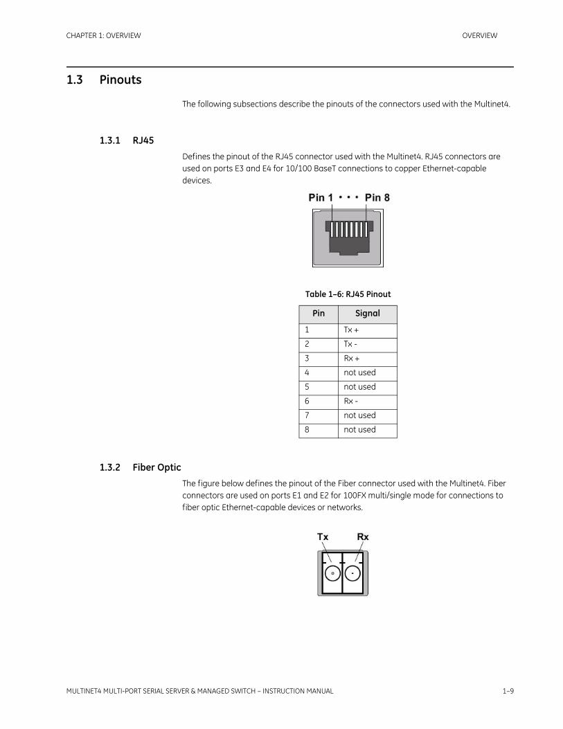
1.3 Pinouts
The following subsections describe the pinouts of the connectors used with the Multinet4.
1.3.1 RJ45Defines the pinout of the RJ45 connector used with the Multinet4. RJ45 connectors are used on ports E3 and E4 for 10/100 BaseT connections to copper Ethernet-capable devices.
1.3.2 Fiber OpticThe figure below defines the pinout of the Fiber connector used with the Multinet4. Fiber connectors are used on ports E1 and E2 for 100FX multi/single mode for connections to fiber optic Ethernet-capable devices or networks.
Table 1–6: RJ45 Pinout
Pin Signal
1 Tx +
2 Tx -
3 Rx +
4 not used
5 not used
6 Rx -
7 not used
8 not used

1–10 MULTINET4 MULTI-PORT SERIAL SERVER & MANAGED SWITCH – INSTRUCTION MANUAL
OVERVIEW CHAPTER 1: OVERVIEW
1.3.3 DB9 (Female) – Console PortThe figure below defines the pinout of the DB9 female connector for the console port for asynchronous or bit-oriented connections.
1.3.4 Phoenix Connector – Alarm PortThe figure below defines the pinout of the Phoenix 3-pin plug used with the alarm port on the Multinet4.
Table 1–7: LC Pinout
Port Signal
Tx Transmit
Rx Receive
Table 1–8: DB9 Pinout
Pin Name Dir. Description
1 DCD In Data Carrier Detect from DCE.
2 RXD In Receive Data from DCE.
3 TXD Out Transmit Data to DCE.
4 DTR Out Data Terminal Ready to DCE.
5 GND Pwr Signal Ground.
6 DSR In Data Set Ready from DCE.
7 RTS Out Request To Send.
8 CTS In Clear To Send.
9 RI In Ring Indicator from DCE.

CHAPTER 1: OVERVIEW OVERVIEW
MULTINET4 MULTI-PORT SERIAL SERVER & MANAGED SWITCH – INSTRUCTION MANUAL 1–11
1.3.5 Phoenix Connectors – Serial PortsThe figure below defines the pinout of the Phoenix 6-pin connector used with serial ports on the Multinet4.
.
Note A 3/32” slotted screwdriver is required to connect/disconnect serial cables to/from the Phoenix 6-pin connector.
Serial ports can be configured as RS232 or RS485 interfaces. Make sure to configure the correct interface standard before connecting to the device. Improper setup can result in damage to the unit.
Pin Signal
1 NC1 - normally closed 1
2 COM1 - common 1
3 NO1 - normally opened 1
Table 1–9: Phoenix 6-pin Pinout
Pin RS232 RS485
S1
1 GND COM
2 RX1 RTX1-
3 TX1 RTX1+
S2
4 GND COM
5 RX2 RTX2-
6 TX2 RTX2+
S1/S

1–12 MULTINET4 MULTI-PORT SERIAL SERVER & MANAGED SWITCH – INSTRUCTION MANUAL
OVERVIEW CHAPTER 1: OVERVIEW
1.4 Features and Benefits
Multinet4 Multi-Port Serial Server & Managed Switch provides secure multiprotocol networking in compact, rugged packages purpose-built for power utility substations and other harsh environments. Cyber-security protection is assured by encrypted per-connection SSL, and port security features.
1.4.1 Multinet4 Multi-Port Serial Server & Managed SwitchThe Multinet4 Serial Port Server & Managed Switch combines the capabilities of an Ethernet Switch, an Async-to-TCP/IP Terminal Server in a single integrated device.
Dual fiber Ethernet connectivity coupled with Rapid Spanning Tree ensure resilient backbone communications.
The Multinet4 provides full perimeter protection when used as a terminal server at remote critical facilities. Per-session encrypted SSL capabilities permit fine-grained security extended to end-point connections when used as a distributed terminal server in larger installations.
The Multinet4 is a multi-function, multi-protocol networking platform, purpose-built for distributed industrial automation applications such as Supervisory Control and Data Acquisition (SCADA) systems.They support a wide range of communications interfaces used by industrial devices, enabling multiple generations of remote devices and support systems to be consolidated onto a single integrated network infrastructure. The Multinet4 also operates effectively in extremely harsh environmental conditions such as those within power utility substations, pumping stations, treatment plants, transportation systems, pipelines and wind farms. This robustness is primarily due to extended-range specifications in areas such as electromagnetic interference, temperature and electrical surges. Most other networking products will fail when facing these conditions.
The Multinet4 has been rigorously tested to extreme industrial specifications for temperature, electrical surge protection and immunity. It is packaged in a steel or steel and aluminum case with no fans or moving parts and has been subjected to manufacturing test and control processes that include temperature cycling and prolonged product burn-in to ensure reliability delivered to the field. Physical product reliability is complemented by advanced network resiliency features that enable redundant and dual-routed network designs that protect network availability despite facility/element failures.

CHAPTER 1: OVERVIEW OVERVIEW
MULTINET4 MULTI-PORT SERIAL SERVER & MANAGED SWITCH – INSTRUCTION MANUAL 1–13
1.4.2 Features SummaryThe table below summarizes the hardware features of the Multinet4.
The table below summarizes the features of the Multinet4.
Table 1–10: Hardware Features Summary
Feature Details
Connectivity • 4 Ethernet ports
— 2 100FX multi/single mode Fiber, ST, SC, and LC
— 2 10/100 BaseT, RJ45 Auto-Negotiation and Auto-MDIX
OR— 4 10/100 BaseT, RJ45 Auto-Negotiation and
Auto-MDIX• 4 programmable RS232/485 serial ports
Power Options • High (90 -250 VAC or VDC)
• Low (24-48 VDC)
Mounting Options • Panel
• DIN-rail
• 19” rack
• 19" rack reverse
Table 1–11: Software Features Summary
Feature Details
Serial Port Management • Up to 16 serial profiles
• Serial data statistics
• RS-232 (Full/Half) & RS-485 (Full/Half) supported via software selection
• Data rates from 1200 baud to 115200 bps
• 7 or 8 data bits
• 1, 1.5, or 2 stop bits
• Even, Odd, or No Parity
• Hardware and Software (XON/XOFF) Flow Control
• Packetization options
— Forward on specific character, idle time, or packet size
— Turnaround timer

1–14 MULTINET4 MULTI-PORT SERIAL SERVER & MANAGED SWITCH – INSTRUCTION MANUAL
OVERVIEW CHAPTER 1: OVERVIEW
Terminal Server • Active, passive, and mixed connection modes
• Telnet and raw TCP sessions
• Multiple incoming connections per serial port
Ethernet Port Management • Supported media types include 10/100BaseTX and 100FX
• 10, 100, or Auto speed selections for 10/100BaseTX Auto-Negotiation and Auto-MDIX
• Half or full duplex operation for 10/100BaseTX
• Ethernet frame statistics
• Port Rate Limiting based on packet type (broadcast, multicast, flood, all)
• Port Mirroring
Ethernet Switching • Maximum Station Cache capacity of 1,024 random MAC addresses
• Up to 64 static MAC addresses
• Purge Dynamic Cache Entries
• 802.1D-compliant Learning Bridge
Rapid Spanning Tree Protocol (RSTP))
• STP
• RSTP
VLANs • Up to 16 different VLANs
• Tagged and untagged operation
• VLAN security (tag-based filtering)
• Optional egress tag stripping
QoS • Flexible flow-based DiffServ marking for all routed packets
• Configurable mapping of DiffServ marking to 802.1p priority tag for all routed packets
• 4-Level priority queuing for Ethernet switching based on IEEE 802.1p tag, IP DiffServ marking, or ingress port.
Security • Secure Web Server using HTTP over SSL (https://)
• User authentication via RADIUS
• Authenticated and encrypted terminal server connections over SSL
• RSA public key and X.509 certificate management and generation
• Web-based upload of new keys and certificates
• Supports a number of SSL and TLS cipher suites that include support for RSA public keys, 3DES/AES/RC4 encryption, and MD5/SHA1 hashing
Table 1–11: Software Features Summary
Feature Details

CHAPTER 1: OVERVIEW OVERVIEW
MULTINET4 MULTI-PORT SERIAL SERVER & MANAGED SWITCH – INSTRUCTION MANUAL 1–15
Embedded Web Server(HTTP/HTTPS)
• Primary User Interface
• Compatible with standard web browsers (such as Internet Explorer or Firefox)
User Account Management • Configurable security policies
• Up to 16 user accounts
• Stored passwords are hashed using MD5
Configuration File Management • XML Configuration Files
• Web-based Upload/Download
• Multiple configurations stored in Flash File System
Software Image Management • Software upgrade with revert capability
• Web-based upload of new software images
Time and Date Management • Real-time clock support
• Active or passive-mode SNTP client
• Time offsets, time zone and Daylight Saving Time support
• Up to 3 SNTP servers can be specified for redundancy
Event Logging • Flexible logging options
• Log files stored in flash file system
• SYSLOG capability
• Up to 5 remote collectors may be specified
SNMP v1/v2c/v3 Agent • Supports User-based Security Model (USM) when v3 is enabled
• MIB-II and SNMPv2 Traps
• Up to 4 remote management/trap destinations may be specified
• Proprietary Enterprise MIB
Modbus/TCP • Modbus/TCP to Modbus/RTU or Modbus/ASCII encapsulation
• Support for multiple masters and slaves
• Maps Modbus device addresses to configurable remote IP addresses
• Enables multi-master access to slaves on a single bus by serializing Modbus requests at the server, a capability not possible in normal serial Modbus
Protocol Monitor • Sniffs ingress and egress packets on any port
• Filter by MAC address, IP address, TCP port, or protocol
• Displays frame addresses, ports, protocol identifier, and data payload
Table 1–11: Software Features Summary
Feature Details

1–16 MULTINET4 MULTI-PORT SERIAL SERVER & MANAGED SWITCH – INSTRUCTION MANUAL
OVERVIEW CHAPTER 1: OVERVIEW

MULTINET4 MULTI-PORT SERIAL SERVER & MANAGED SWITCH – INSTRUCTION MANUAL 2–1
Multinet4 Multi-Port Serial Server & Managed Switch
Chapter 2: Getting Started
Digital EnergyMultilin
Getting Started
The Multinet4 Multi-Port Serial Server & Managed Switch provides connectivity to asynchronous and Ethernet traffic through four programmable serial ports, two 10/100 BaseT Ethernet ports for copper line connections, and two 100FX multimode (MM) or singlemode (SM) for fiber optic connections.
2.1 Installation
The Multinet4 is designed to be installed in standard 19" racks, on a DIN rail system, or on a panel.
2.1.1 ToolsRegardless of the mounting system you are using, you will need the following tools:
• Two screw drivers – one phillips head and one slot.
• A torque wrench (rated for ten and 32 inch pounds, or 1.1 Nm and 3.6 Nm)
• A wrench to connect a ground wire from the device chassis to a ground
The instructions in this chapter cover only the physical installation. System configuration is handled through a web-based interface and is described in Chapter 4.
2.1.2 Site SuitabilityBe sure that your installation site meets the following criteria:
• Conforms with the temperature and humidity ranges, detailed in Table 1–2:: Environmental Specifications.
• Can meet the power requirements, detailed in Table 1–3:: Power Requirements.
• Will remain stable after the addition of the 5 lb. Multinet4.
• Permits at least two inches (5.1cm) of space between the Multinet4 and any other heat-producing device.

2–2 MULTINET4 MULTI-PORT SERIAL SERVER & MANAGED SWITCH – INSTRUCTION MANUAL
GETTING STARTED CHAPTER 2: GETTING STARTED
2.1.3 Wiring and Grounding GuidelinesThe Multinet4 requires several different types of connectors, cables, and wires. Requirements and recommendations are listed below:
It is mandatory that an accessible disconnect is provided in the Installation wiring
2.1.4 Fiber Optic SafetyBefore installing the Multinet4 you should be aware that devices that employ laser technology, such as the fiber optical LC ports and associated cabling, can be dangerous. Do not look directly into a fiber optic port or into the end of a fiber optic line. Doing so could cause injury to your eye or blindness. Always assume that there is laser activity in the line or port, even if the device is powered down. As a reminder, whenever this manual calls for the handling of fiber optic lines, those instructions will be accompanied by a “Laser Warning,” as follows:
DO NOT LOOK INTO A FIBER OPTIC CABLE OR PORT! These can produce invisible light that may do serious eye damage. Always assume that fiber optic cables or ports are actively radiating light energy.
Fiber The fiber cables connected to the Multinet4 must be:
• non-dispersion shifted, single mode (SM)
or
• multi-mode (MM) fiber cables defined by the Telcordia Technologies General Recommendation 20-CORE standard
and
• terminated with LC, ST, and SC connectors
Grounding The primary ground stud located on the rear of the chassis must be used to connect to an approved ground with a wire meeting the following criteria:
• 14 AWG (minimum)
• a maximum of five feet in length
• terminated on the ground lug side with a #10 ring lug
Facility Power The facility power cabling attached to the Multinet4 chassis must meet the following criteria:
• cabling constructed using 14 AWG stranded wire
• cable firmly attached to the terminal holes of the non-polarized power unit, as illustrated in FIGURE 2–11:: Non-Polarized Power Input.
• cable routed and strain relieved to the chassis according to good wiring practices
Copper Copper I/O cables and connectors must be shielded.

CHAPTER 2: GETTING STARTED GETTING STARTED
MULTINET4 MULTI-PORT SERIAL SERVER & MANAGED SWITCH – INSTRUCTION MANUAL 2–3
2.1.5 Fiber Optic HandlingContamination from dust, dirt, oils from the hands and other sources can impede the transmission and reception of optical signals through the optical fibers.When handling the optical connectors and fiber cables, follow these precautions to minimize the contamination of the connectors and ports:
• Cover optical connectors and ports with dust caps when they are not in use.
• Do not touch fiber tips or the interior of optical ports when handling fiber cables and connectors.
• Clean fiber optic connectors as described in 2.4.2.1: Cleaning Connectors, prior to making any optical connection.
• Clean optical ports as described in 2.4.2.2: Cleaning Optical Ports if contaminants or degraded performance are noted on the interface.
Fiber optic connectors should be cleaned after each use and optical ports should be cleaned if you notice contamination or degraded performance.
Fiber optic cables and connectors are fragile and can be easily broken through rough handling. When handling fiber optic media, take the following precautions:
• Do not strike the fiber cable with tools.
• Do not pinch, crimp, or compress the jacketing of the optical cable.
• Do not use less than the minimum bend radius of 3 inches (7.62 cm) when routing or coiling cables.
2.1.6 External ConnectionsYou can speed up the installation of the Multinet4 by having the following equipment and information on hand before beginning:
• A supply of cables and connectors of the required types.
• IP addresses for new devices and any existing devices you will be connecting to.
• Your notes on naming conventions and end point information.

2–4 MULTINET4 MULTI-PORT SERIAL SERVER & MANAGED SWITCH – INSTRUCTION MANUAL
GETTING STARTED CHAPTER 2: GETTING STARTED
2.2 Unpacking
Unpack and inspect the Multinet4.
The Multinet4 is shipped with the following items in the box:
• Multinet4 unit
• Appropriate mounting brackets (19’ rail, or DIN rail, or panel), with screws
• Document CD-ROM
• Console Cable - DB9 terminations, 10' long
• Ethernet cable - RJ45 terminations, 10' long
Be sure that all the equipment you have ordered is included in the shipment.
Remove the unit from the styrofoam end caps and inspect the Multinet4 chassis for dents or other shipping related damage. Report any damage immediately to GE Multilin Customer Support and DO NOT INSTALL the unit.

CHAPTER 2: GETTING STARTED GETTING STARTED
MULTINET4 MULTI-PORT SERIAL SERVER & MANAGED SWITCH – INSTRUCTION MANUAL 2–5
2.3 Installation of the Multinet4 Unit
To install the Multinet4 you must first
• Mount it
• Make the ground and power connections.
• Connect the network cables
2.3.1 Mounting
Before mounting, please note the following:
1. Elevated Operating Ambient - If installed in a closed or multi-unit rack assembly, the operating ambient temperature of the rack environment may be greater than room ambient. Therefore, consideration should be given to installing the equipment in an environment compatible with the maximum ambient temperature (Tma) specified by the manufacturer.
2. Reduced Air Flow - Installation of the equipment in a rack should be such that the amount of air flow required for safe operation of the equipment is not compromised.
3. Mechanical Loading - Mounting of the equipment in the rack should be such that a hazardous condition is not achieved due to uneven mechanical loading.
4. Circuit Overloading - Consideration should be given to the connection of the equipment to the supply circuit and the effect that overloading of the circuits might have on overcurrent protection and supply wiring. Appropriate consideration of equipment nameplate ratings should be used when addressing this concern.
5. Reliable Earthing - Reliable earthing of rack-mounted equipment should be maintained. Particular attention should be given to supply connections other than direct connections to the branch circuit (e.g. use of power strips)."
2.3.1.1 Mounting Hardware
Your Multinet4 shipment includes the mounting hardware you have ordered as appropriate to your site.This hardware is one of:
• A pair of 4.5” brackets for conventional mounting in a 19” rail system (that is, with I/O connections on the “aisle side” of the rack)
• A pair of 8.75” brackets for reverse mounting in a 19” rail system (that is, with I/O connections on the “wire side” of the rack)
• A pair of 1.5” brackets for mounting on a panel.
• A DIN rail mounting bracket.
2.3.1.2 Mounting in a 19” Rail System - General
The Multinet4 device can be mounted in a 19” rail system with the I/O connectors on the aisle side and the power and ground connectors on the wire side (conventional mounting) or in the reverse configuration.
2–6 MULTINET4 MULTI-PORT SERIAL SERVER & MANAGED SWITCH – INSTRUCTION MANUAL
GETTING STARTED CHAPTER 2: GETTING STARTED
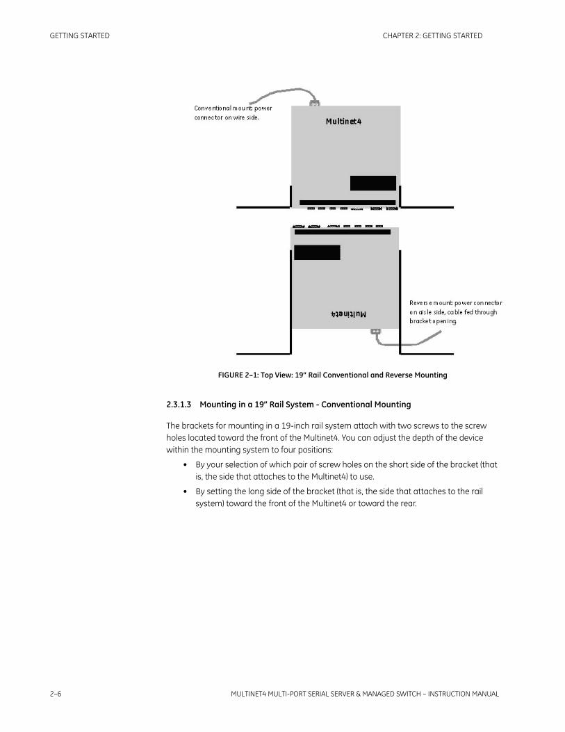
FIGURE 2–1: Top View: 19” Rail Conventional and Reverse Mounting
2.3.1.3 Mounting in a 19” Rail System - Conventional Mounting
The brackets for mounting in a 19-inch rail system attach with two screws to the screw holes located toward the front of the Multinet4. You can adjust the depth of the device within the mounting system to four positions:
• By your selection of which pair of screw holes on the short side of the bracket (that is, the side that attaches to the Multinet4) to use.
• By setting the long side of the bracket (that is, the side that attaches to the rail system) toward the front of the Multinet4 or toward the rear.

CHAPTER 2: GETTING STARTED GETTING STARTED
MULTINET4 MULTI-PORT SERIAL SERVER & MANAGED SWITCH – INSTRUCTION MANUAL 2–7
FIGURE 2–2: 19” Rail Conventional Mounting brackets
FIGURE 2–3: 19” Rail Conventional Mounting - Dimensional Drawing
2.3.1.4 Mounting in a 19” Rail System - Reverse Mounting
The brackets provided for reverse mounting have an opening in their forward projecting parts to accommodate the power cable.
CONSOLE
ALARM S1
S2
S3
S4
E1 E2E3 E4
18.9in (48cm)9.4in (23.9cm) 4.75in (12.07cm)4.75in (12.07cm)
1.7in(4.32cm)
1.25in(3.18cm)
18.2in (46.2cm)

2–8 MULTINET4 MULTI-PORT SERIAL SERVER & MANAGED SWITCH – INSTRUCTION MANUAL
GETTING STARTED CHAPTER 2: GETTING STARTED
FIGURE 2–4: 19” Rail Reverse Mounting brackets
FIGURE 2–5: 19” Rail Reverse Mounting - Dimensional Drawing
2.3.1.5 Mounting on a Panel
The brackets for mounting on a panel attach with two screws to the screw holes located toward the rear of the Multinet4. You can adjust the distance of the Multinet4 from the panel to two positions by your selection of which pair of screw holes to use in attaching the bracket to the Multinet4.
18.9in (48cm)9.4in (23.9cm) 4.75in (12.07cm)4.75in (12.07cm)
1.7in(4.32cm)
1.25in(3.18cm)
18.2in (46.2cm)
24-48V
1.3A
NO
N-P
OLA
RIZE
D
Serial No:
0650 0034
DX800-01-L-P

CHAPTER 2: GETTING STARTED GETTING STARTED
MULTINET4 MULTI-PORT SERIAL SERVER & MANAGED SWITCH – INSTRUCTION MANUAL 2–9
FIGURE 2–6: Panel Mounting brackets
FIGURE 2–7: Panel Mounting - Dimensional Drawing
12.7in (32.26cm)
11.1in (28.2cm)
9.4in (23.88cm)
8.8i
n (2
2.35
cm)
5.48
in (1
3.9c
m)
0.5in (1.27cm)
0.5in (1.27cm)
1.65in (4.2cm)
0.85in (2.16cm)

2–10 MULTINET4 MULTI-PORT SERIAL SERVER & MANAGED SWITCH – INSTRUCTION MANUAL
GETTING STARTED CHAPTER 2: GETTING STARTED
2.3.1.6 Mounting in a DIN Rail System
The DIN rail bracket rides on the bottom of the Multinet4 and is attached with four screws into the two pair of screw holes located toward the back of the Multinet4. The bracket attaches to the DIN rail by means of a pair of stationary prongs near the top of the bracket and a single spring-loaded prong (the release mechanism) toward the bottom of the bracket.
To fasten the Multinet4 into a DIN rail system begin by slipping the upper pair of prongs over the top of the rail. Then, while depressing the spring-loaded release mechanism (as illustrated in the figure below), press the Multinet4 flush against the DIN rail and remove the screwdriver to allow the release mechanism to close. Check to make sure that the top and bottom prongs on the bracket are securely attached to the DIN rail.
When the Multinet4 is fastened into the DIN rail system it can be released by downward pressure on the release mechanism. The DIN rail bracket supplied with the Multinet4 is equipped with a metal “tail” that projects below the chassis of the mounted Multinet4. To unmount the Multinet4 insert the tip of a screwdriver into the slot a the bottom of this tail and pull up on the handle of the screwdriver to force the release mechanism down.
FIGURE 2–8: Multinet4 with DIN Rail bracket attached

CHAPTER 2: GETTING STARTED GETTING STARTED
MULTINET4 MULTI-PORT SERIAL SERVER & MANAGED SWITCH – INSTRUCTION MANUAL 2–11
FIGURE 2–9: DIN Rail Mounting - Dimensional Drawing
2.3.2 Connecting Facility PowerThe Multinet4 comes in either high or low voltage models. The unit does not have a power on/off switch and is active when the power is connected.
ELECTRICAL WARNING: Always ensure that the ground connection is made prior to connecting facility power to the Multinet4. The ground provides a protective circuit connection to ground in cases of transients and power surges. Connect the facility power to a DC or AC unit as described in the following sections.
2.3.2.1 Making the Ground and Power Connections
The Multinet4 provides a hardened DC or AC power supply for industrial applications and/or hostile environments. The ground lug and power supply connector are located on the rear of the unit as shown in the figure below.
9.4in (23.88cm)
6.3i
n (1
6cm
)
9.14
in (2
3.22
cm)
5.94
in (1
5.09
cm)
2.89
in
2.85
in
<-><->
2.43in(6.17cm)
1.7in(4.32cm)
.35in.38in
(.95cm)
< >

2–12 MULTINET4 MULTI-PORT SERIAL SERVER & MANAGED SWITCH – INSTRUCTION MANUAL
GETTING STARTED CHAPTER 2: GETTING STARTED
FIGURE 2–10: Ground and Power Connections
ELECTRICAL WARNING: Verify that a proper ground connection is made from the ground lug to facility ground prior to connecting power to the Multinet4. Failure to have a proper ground path could cause serious injury or death to personnel in cases of power surges.
Making the Ground Connection
The ground wire should be 14 AWG terminated with a #10 ring lug.
Make the facility ground connection as follows:
Loosen the ground bolt on the chassis, insert the #10 ring lug, and tighten the ground bolt.
Connect the other end of the ground wire to the facility ground.
Making the Power Connection
The power wires should be 14 AWG terminated with a #6 ring lug. Smaller wires may be used, down to 18 AWG, but verify that they meet your local electrical requirements.
Connect the power to the unit as follows.
ELECTRICAL WARNING: Ensure that power is disconnected from wiring prior to handling! Check the voltage rating next to the power connector - verify that it matches the power source.
Remove the plug portion of the power connector by loosening the two captive mounting screws.
Strip back 1/4" off the insulation of the wires that will connect the unit to the power source.
Loosen saddle screws and insert each conductor firmly into a terminal hole of the plug (note: this connection is not polarity sensitive.)
Visually inspect that no strands of wire are straying out of the hole, potentially shorting to ground or the other conductor. Tighten the saddle screws until the wires are secure.

CHAPTER 2: GETTING STARTED GETTING STARTED
MULTINET4 MULTI-PORT SERIAL SERVER & MANAGED SWITCH – INSTRUCTION MANUAL 2–13
Re-insert the plug into the power connector and secure the two captive mounting screws.
FIGURE 2–11: Non-Polarized Power Input
2.3.3 Connecting to the Console Port and the Alarm Port
2.3.3.1 Console Port
Use a DB9 null-modem cable or a DB9-to-USB null-modem cable, to connect the Multinet4 console port (the RS232 port) to the PC.
2.3.3.2 Alarm Port
Resevered for future use.
2.3.4 Connecting Network CablesThere are three types of connections that can be made to the Multinet4. They are serial, Ethernet copper, and Ethernet fiber optic. The following sections describe each type of connection separately.
2.3.4.1 Connecting Serial Cables
This procedure assumes that one end of the Serial device cable is already attached to the end unit. Be aware of the serial port numbering scheme when installing the cables see (see section1.3: Pinouts). The ports are configured in software later on and if a device is accidentally connected to the wrong port it will be difficult to detect.
Connect cables to the serial ports as described below (A 3/32” slotted screwdriver is required.):
1. Remove the plug portion of the phoenix connector by loosening the two captive mounting screws.
2. Strip back 1/4" off the insulation of the wires.
3. Loosen saddle screws and insert each conductor firmly into a terminal hole of the plug
4. Visually inspect that no strands of wire are straying out of the hole, potentially shorting to ground or the other conductor.
saddle screws
captive mounting screws
terminal holes

2–14 MULTINET4 MULTI-PORT SERIAL SERVER & MANAGED SWITCH – INSTRUCTION MANUAL
GETTING STARTED CHAPTER 2: GETTING STARTED
5. Tighten the saddle screws until the wires are secure.
6. Re-insert the plug into the phoenix connector and secure the two captive mounting screws.
Note Serial cables must be shielded. It is recommended that high quality Belden 9843 cables be used whenever possible to provide reliable serial communication.
2.3.4.2 Connecting RJ45 Twisted Pair
The RJ45 ports of the Multinet4 can be connected to the following two media types: 100Base-TX and 10Base-T. CAT Five cables should be used when making 100Base-TX connections. When the ports are used as 10Base-T ports, CAT.3 may be used. In either case, the maximum distance for unshielded twisted pair cabling is 100 m (328 ft .).
Note
It is recommended that high quality CAT. 5 cables (which work with 10 Mb and 100 Mb) be used whenever possible to provide flexibility in a mixed-speed network, as dual-speed ports are auto-sensing for 10 and 100 Mb/s.The following procedure describes how to connect a 10Base-T or 100Base-TX twisted pair segment to the RJ45 port. The procedure is the same for both unshielded and shielded twisted pair cables.
Using standard twisted pair media, insert either end of the cable with an RJ45 plug into the RJ45 connector of the port. Even though the connector is shielded, either unshielded or shielded cables may be used.
Connect the other end of the cable to the corresponding device.
Use the LINK LED to ensure connectivity by noting that the LED will be illuminated when the unit is powered and connection is established.
2.3.4.3 Connecting ST-type Fiber Optics (twist-lock)
The following procedure applies to installations using modules with ST-type fiber connectors.
Before connecting the fiber optic cable, remove the protective dust caps from the tips of the connectors on the module.Save these dust caps for future use.
Wipe clean the ends of the dual connectors with a soft cloth or lintfree lens tissue dampened in alcohol.Ensure the connectors are clean before proceeding.
Note
One strand of the duplex fiber optic cable is coded using color bands at regular intervals.The color-coded strand must be used on the associated ports at each end of the fiber opticsegment.
Connect the transmit (TX) port on the module (light colored post) to the receive (RX) port of the remote device.Begin with the color-coded strand of the cable for this first TX-to-RX connection.

CHAPTER 2: GETTING STARTED GETTING STARTED
MULTINET4 MULTI-PORT SERIAL SERVER & MANAGED SWITCH – INSTRUCTION MANUAL 2–15
Connect the receive (RX) port on the module (dark colored post) to the transmit (TX) port of the remote device.Use the non-color coded fiber strand.
The LINK LED on the module will illuminate when a connection has been established at both ends (assuming power is ON). If LINK is not lit after cable connection, the cause may be improper cable polarity. Swap the fiber cables at the module connector to remedy this situation.
2.3.4.4 Connecting SC-type or LC-type Fiber Optics (snap-in)
The following procedure applies to installations using modules with SC-type or LC-type connectors.
When connecting fiber media to SC/LC connectors, simply snap the two square male connectors into the module’s SC/LC female jacks until the click and secure.
2.3.4.5 Connecting Single-mode Fiber Optics
When using single-mode fiber cable, be sure to use single-mode fiber port connectors. Single-mode figer cable has a smaller diameter than multi-mode fiber cable (9/125 microns for single-mode versus 50/150 or 62.5/125 microns for multi-mode, where xx/yy represent the core diameters and the core plus cladding respectively). Single-mode fiber allows full bandwidth at longer distances and may be used to connect 10 Mb nodes up to 10 Km.
The same connection procedures for multi-mode fiber apply to single-mode fiber connectors. Follow the steps listed in 2.3.4.3: Connecting ST-type Fiber Optics (twist-lock) and 2.3.4.4: Connecting SC-type or LC-type Fiber Optics (snap-in) shown above.

2–16 MULTINET4 MULTI-PORT SERIAL SERVER & MANAGED SWITCH – INSTRUCTION MANUAL
GETTING STARTED CHAPTER 2: GETTING STARTED
2.4 Maintenance
The Multinet4 is designed to be replaced as a unit. There are no servicing requirements and there are no user-repairable components in this device. Maintenance is limited to replacing the unit and cleaning any fiber optic connectors and ports.
The following sections detail disconnecting all connections to the chassis, removing the chassis, cleaning optical devices and packing the Multinet4 for return to the manufacturer. If it is still possible to connect a terminal to the malfunctioning Multinet4 and retrieve any configuration data from the device, do so prior to removing power.
2.4.1 Removing the Multinet4Removing the Multinet4 entails disconnecting the power lines, disconnecting the network cabling, and removing the chassis from the rack or other installation location. The unit can then be packed for shipment to the manufacturer.
2.4.1.1 Disconnecting Power and Ground Lines
ELECTRICAL WARNING: Before disconnecting either AC or DC power connections at the Multinet4 ensure that the facility power has first been turned off. Failure to shut power off prior to removing the power connections could expose you to dangerous voltages causing injury or death.
Follow the procedure below to disconnect the power and ground lines.
Verify that power to the Multinet4 is turned off.
Use a screw driver to loosen the two screws that tighten the wire clamps in the non-polarized power connector.
Remove the wires from the connector.
ELECTRICAL WARNING: If the wires are not to be used immediately properly insulate them to ensure that an accidental turning on of the power will not cause a short or electrical hazard.
Remove the ground wire from the chassis by loosening the Ground Lug.
2.4.1.2 Disconnecting Network Cables
The sequence for removal of the serial and Ethernet cables is not important, but it is important to note that there are active devices connected to each end of the cable.
Remove all wires from the Phoenix serial ports by unscrewing the saddle screws and pulling one wire off one port. (Label the wire with the port number if the cable is to be reconnected at some later time.)
Remove the Ethernet RJ45 connectors from the Ethernet ports by pressing on the clip on the underside of the modular connector and pulling the connector straight out. (Label the connector with the port number if the cable is to be reconnected at some later time.)

CHAPTER 2: GETTING STARTED GETTING STARTED
MULTINET4 MULTI-PORT SERIAL SERVER & MANAGED SWITCH – INSTRUCTION MANUAL 2–17
LASER WARNING: DO NOT LOOK INTO A FIBER OPTIC CABLE OR PORT! These can produce invisible light that may do serious eye damage. Always assume that fiber optic cables or ports are actively radiating light energy.
Following the safe handling procedures for fiber optic cables and connectors, remove any fiber optic cable connected to the Ethernet fiber ports. Immediately install dust caps on the cable end and the fiber port. (Label the connector with the port number if the cable is to be reconnected at some later time.)
2.4.1.3 Packing the Multinet4 for Shipment
If you have saved the shipping box that your Multinet4 was received in then add the end styrofoam pieces around the chassis and place the unit in the box. Please contact customer support to receive a valid RMA number so that this item is either repaired and returned or credited to your account. Products without a proper RMA number will not be accepted for repair by GE Multilin.
If you have not saved the original shipping container then place the unit in a box so that normal shipping activities will not cause any damage to the unit. GE Multilin has no responsibility for the product during return shipping.
2.4.2 Cleaning Fiber Optic DevicesThis section covers the cleaning requirements and procedures for the fiber optic cable connectors and the optical ports on the Multinet4. Clean the connectors after each use and the optical ports when contamination is suspected or there is a performance degradation which may be attributable to contamination. All fiber optic connectors and optical ports should be capped with dust caps when not in use.
The cleaning materials used should be rated for fiber optic devices. Specifically cloth, wipes and swabs should be lint-free, non-abrasive and free of additives. Cleaning fluids should be restricted to optical-grade isopropyl alcohol. Canned (compressed) air should be used to blow out dust and particulate matter and to dry residual isopropyl alcohol after cleaning.
2.4.2.1 Cleaning Connectors
These instructions are recommended each time a fiber optic connector is used. Clean the fiber optic connectors as follows:
Blow out any dust or particulate matter from the connector end, using canned air.
Wipe out the connector end surfaces with a cloth or pad saturated in isopropyl alcohol.
Blow dry the connector surfaces, using canned air, by directing the air flow across the tip but not directly down onto the tip.
Using care not to touch the fiber tip, install a dust cap or connect to an optical port.
2–18 MULTINET4 MULTI-PORT SERIAL SERVER & MANAGED SWITCH – INSTRUCTION MANUAL
GETTING STARTED CHAPTER 2: GETTING STARTED
2.4.2.2 Cleaning Optical Ports
These instructions are recommended only when there is evidence of contamination or when reduced performance has been detected. Clean the optical ports as follows:
If required, remove the fiber optic connector from the optical port and clean the connector as described in “Cleaning Connectors,” above.
Insert the extension tube, supplied with the canned air, into the canned air nozzle and blow out the optical port. Use care not to touch the bottom of the optical port.
Reconnect the fiber optic connector removed in step 1.
If degraded performance persists, perform the following additional steps:
Remove the fiber optic connector and place a dust cap on the end.
Using a small-head, lint-free swab gently wipe out the optical port. Repeat steps 2 and 3 above.

CHAPTER 2: GETTING STARTED GETTING STARTED
MULTINET4 MULTI-PORT SERIAL SERVER & MANAGED SWITCH – INSTRUCTION MANUAL 2–19
2.5 Software Management
The EnerVista Multinet4 Setup software or the Web Administrator interface or CLI interface can be used to manage and configure the Multinet4. The EnerVista Multinet4 Setup software is the preferred method to edit the most common used setting. The setup software connects to the unit through the Ethernet port.
Multinet4 is implemented by an easily upgradeable software image and by configuration files.
Software images can be upgraded with the EnerVista Multinet4 Setup > Maintenance > Upload Firmware, which loads an executable software image into non-volatile memory.
Configuration files can be maintained and upgraded with EnerVista Multinet4 Setup > Advanced Setting > Administration > Configuration screen.
The Multinet4 comes with a factory-supplied software image and configuration file. After you have completed the hardware installation you need only replace the default IP address with another that places your PC and the Multinet4 on the same subnet. You can then access the Multinet4’s supervisory software and begin to configure your system.
2.5.1 Configuring a New IP AddressThe Multinet4 Serial Port Server & Managed Switch is delivered with a default IP address 192.168.1.2. The user must change this address to one that is valid on the user’s network. The Multinet4 Setup software provides a fast way to configure a new IP address through the Ethernet Port. (By factory default, only E4 is enabled.)
1. Make sure the IP address for the PC running the Multinet4 Setup Software is in the same subnet as the new desired IP for the Multinet4. • In this example, the desired New IP information of the Multinet4 is
3.94.247.232 with subnet mask of 255.255.255.0.
• The IP setting for the PC is configured as 3.94.247.100 with subnet mask of 255.255.255.0.
2. Launch EnerVista Multinet4 Setup > Device Setup, then click Add site, and then click Add Device. By default, the device will be shown as configured over 192.168.1.2 in the IP Address field as shown below.
3. Enter the desired network parameters (New IP address, subnet mask and gateway) of the Multinet4 into the Network settings field.

2–20 MULTINET4 MULTI-PORT SERIAL SERVER & MANAGED SWITCH – INSTRUCTION MANUAL
GETTING STARTED CHAPTER 2: GETTING STARTED
4. Click Save to configure the new IP address information to the Multinet4, wait until the new IP address is read back and showing in the IP Address field as shown below.

CHAPTER 2: GETTING STARTED GETTING STARTED
MULTINET4 MULTI-PORT SERIAL SERVER & MANAGED SWITCH – INSTRUCTION MANUAL 2–21
5. Click Read Order Code to connect the Multinet4 to read the Order Code and firmware Version. The information will display if the new IP address has been configured successfully..
6. Click OK to exit Device Setup.

2–22 MULTINET4 MULTI-PORT SERIAL SERVER & MANAGED SWITCH – INSTRUCTION MANUAL
GETTING STARTED CHAPTER 2: GETTING STARTED
2.6 The EnerVista Multinet4 Setup Software Overview
The EnerVista Multinet4 Setup software interface is the preferred method to manage and configure the system. Its main window supports the following primary display components:
1. Title bar which shows the pathname of the active data bar.
2. Main window tool bar.
3. Site list control bar window.
4. Setting list control bar window.
5. Device data view windows, with common tool bar.
6. Workspace area with data view tabs.
7. Status Bar.
8. Communication status indicator.
12
3
4
5
6
7
8

CHAPTER 2: GETTING STARTED GETTING STARTED
MULTINET4 MULTI-PORT SERIAL SERVER & MANAGED SWITCH – INSTRUCTION MANUAL 2–23
2.7 The Advanced Setting - Administrator Interface Overview
The Advanced Setting - Administrator Interface enables you to view and edit system parameters through the embedded web browser.
2.7.1 Logging in for the First TimeFor the first time logging, the secure site will issue the certificate check shown below.
FIGURE 2–12: Security certificate
Once you click Yes on the security certificate, the browser will prompt you to login.
FIGURE 2–13: Login Screen

2–24 MULTINET4 MULTI-PORT SERIAL SERVER & MANAGED SWITCH – INSTRUCTION MANUAL
GETTING STARTED CHAPTER 2: GETTING STARTED
Note For Windows VISTA, the browser may show a warning message of “Problem with website security certificate”. You will need to regenerate the Multinet4 web server certificate, then import that certificate into IE by following these steps:
1. At the screen - "There is a problem with this website's security certificate," select the Continue to website link.
2. Log in to Multinet4 as an administrator.
3. Verify that your time, date, time zone, and daylight saving time settings are correct.
Incorrect time and date will cause certificate validation errors
4. Expand the "Wizards" menu and click the Certificate Creation link.
5. Select the second option entitled Create a new RSA key pair and your own self-signed certificate.
6. Click the Start button.
7. Enter the following information:
• Certificate Name: This can be anything as long as its unique and less than 24 characters, e.g. "WEB_CERT_2008"
• Algorithm: Recommend changing this to SHA • Number of Days Valid: 180 is default, this can be more or less but
remember that once the certificate is invalid, IE will start harassing you again
• Serial Number: Leave Blank • Subject Country: Enter the two letter ISO 3166 country code (e.g.
US) • Subject State, Locality, Organization, and Organization Unit: can
be most anything • Subject Common Name - This must be the IP address that you
will use to access the web server on the Multinet4.
8. Press the Next button.
9. Wait up to a minute or two... Generating a 1024-bit RSA key takes time.
10. You will see the "Security: Certificates: Local" page and your new certificate should show up in the list.
11. Expand the Security menu.
12. Click on the Web Server link.
13. Select your new certificate in the "Local Certificate" dropdown and press the Apply Settings button.
14. Press the Reload button on your browser.
15. At the screen - "There is a problem with this website's security certificate.” - select the Continue to website link.
16. Click on the tool bar area - "Certificate Error".
A dialog will pop up.

CHAPTER 2: GETTING STARTED GETTING STARTED
MULTINET4 MULTI-PORT SERIAL SERVER & MANAGED SWITCH – INSTRUCTION MANUAL 2–25
17. Click on the View Certificate link.
A new dialog called "Certificate" will pop up.
18. Click the "Install Certificate..." button.
A wizard dialog will appear.
19. Click the Next button.
20. Select Automatically select the certificate store based on the type of certificate and press the Next button.
21. Press the Finish button.
A warning dialog will pop up asking if you really want to install the certificate.
22. Click Yes.
A popup will alert you that "The import was successful".
23. Click OK.
24. Close the "Certificate" dialog by clicking OK.
25. Exit IE 7.
26. Re-open IE 7 and surf back to the Multinet4 server.
27. Log in.
The warning message will no longer appear until your certificate expires.
2.7.2 Administrator Interface OverviewThe figure below is an illustration of a typical administrator screen. Table 2–1:: The Administrator Interface explains the functionality of the areas marked in the illustration.

2–26 MULTINET4 MULTI-PORT SERIAL SERVER & MANAGED SWITCH – INSTRUCTION MANUAL
GETTING STARTED CHAPTER 2: GETTING STARTED
FIGURE 2–14: Administrator Interface
Navigation Area
Global Area
Interaction Area
Table 2–1: The Administrator Interface
Area Name Area Function
Navigation The Navigation area contains a menu tree that can be expanded or collapsed to show all of the available interaction screens. Clicking on a leaf of the menu tree brings up the corresponding screen in the Interaction area.

CHAPTER 2: GETTING STARTED GETTING STARTED
MULTINET4 MULTI-PORT SERIAL SERVER & MANAGED SWITCH – INSTRUCTION MANUAL 2–27
The screen displayed at start-up is the “Virtual Front Panel".
Note The descriptions of the visual display of the Administrator employ the terms “screen,” “form,” “table,” and “button.” These terms have the following meanings.
Screen – the whole meaningful content of your browser, not including browser tool bars, status bars, and the like.
Form – a portion of the screen whose primary purpose is to enable the entering of user-supplied information. A form contains fields that you can fill with keyboard input, by selecting from drop-down menus, or by browsing to select a file on your local system. A form may also contain some read-only information.
Table – a portion of the screen whose primary purpose is to provide the user with information, such as lists of addresses, installed configurations, status reports, etc. A table may or may not contain editable fields. A table often includes a checkbox to enable you to delete the contents of a row in the table.
Buttons – labeled, clickable areas of the screen. Clicking a button performs the action described in its label. Most screens include buttons labeled Apply Settings, to save any changes you have made, and Reset Settings, to undo any changes you have made that have not yet been applied.
Interaction The Interaction area contains an HTML form where you can configure some aspect of the system. This area can also be used to display read-only information such as port statistics or event logs.
Global The Global area contains controls that have a global effect on the current session.
• Click the Revert button to undo any unsaved changes to the system's configuration.
• Click the Save button to save the current system configuration in the active configuration file.
• Click the Save As button to save the current system configuration in a new configuration file.
• Click the Logout button to end the current session.
This area also displays text identifying the user name of the current user, the user-configurable system name of the node being managed, and the IP address of the node.
Table 2–1: The Administrator Interface
Area Name Area Function

2–28 MULTINET4 MULTI-PORT SERIAL SERVER & MANAGED SWITCH – INSTRUCTION MANUAL
GETTING STARTED CHAPTER 2: GETTING STARTED
2.7.3 The Administrator Interface Navigation TreeThe menu tree supported in this release is as follows:
Table 2–2: Menu Tree
Screen Function
Virtual Front Panel An animated view of the device’s ports and LEDs
Administration Tasks
System
System Information View and edit identifying information.
System Status View memory and buffer utilization and queue overflow.
Time
Time: Time and Date Set the system’s time and date.
Time: Zone and DST Specify standard time and daylight savings time for your system.
Time: Persistence On reset use the last known good time and date (for device clocks without battery backup).
SNTP
SNTP: Global Settings Configure mode and frequency of time synchronization.
SNTP: Servers Designate servers that will provide the correct time.
SNMP
SNMP: Global Settings Configure network management (enable SNMP agent, control MIB access).
SNMP: Management Stations
Specify address(es) of station(s) to query SNMP agents.
SNMP: Trap Stations Specify address(es) of station(s) to receive SNMP traps.
SNMP: Users Manage user security provisions.
SNMP: Statistics Monitor 43 measures of SNMP performance.
Authentication
Authentication: Policies Set number of failed logins before lockout and duration of lockout.
Authentication: Accounts Maintain user accounts (names, passwords, etc.)
Authentication: Files Upload new user definitions.
Sessions
Sessions: Policies Set the length of time a login session can be idle before it is automatically terminated.
Sessions: Active Logins View IDs and uptime of active login sessions.
Change Password Change current user’s password.

CHAPTER 2: GETTING STARTED GETTING STARTED
MULTINET4 MULTI-PORT SERIAL SERVER & MANAGED SWITCH – INSTRUCTION MANUAL 2–29
Software Upgrade Install a newer version of software.
Configuration
Configuration: Files View and manage available configuration files.
Configuration: Defaults Restore the system’s default configuration.
System Reboot Shut down and restart the system.
Events Tasks
Logs
Logs: Global Settings Enable logging of events and control logfile number and size.
Logs: Files Displays hyperlinks to available log files.
Syslog
Syslog: Global Settings Enable/disable syslog protocol functionality.
Syslog: Collectors Specify IP addresses of syslog event collectors.
Ethernet Tasks
Ports
Ports: Settings Enable and disable Ethernet ports and set and view configurations (media type, flow control, FEFI).
Ports: Status Check capabilities and operational status of each Ethernet port.
Ports: Summary Statistics View basic performance statistics for each Ethernet port.
Ports: Extended Statistics View detailed performance statistics for each Ethernet port.
Ports: Mirroring Forward packets from one port on a Multinet4 to another for analysis.
Ports: Rate Limits Specify limits on the throughput of certain types of packets.
Bridge
Bridge: Global Settings View or set the aging interval for learned MAC addresses.
Bridge: Static MACs Add or remove static MAC addresses in the bridge MAC address table.
Bridge: Station Cache View a table of MAC addresses and the ports that access them.
RSTP
RSTP: Bridge Settings Configure RSTP settings for the bridge.
RSTP: Port Settings Associate specific Ethernet ports with RSTP values (mode, priority).
RSTP: Bridge Status View RSTP counters and status for the bridge.
RSTP: Port Status View RSTP counters and status for specific Ethernet ports.
Table 2–2: Menu Tree
Screen Function

2–30 MULTINET4 MULTI-PORT SERIAL SERVER & MANAGED SWITCH – INSTRUCTION MANUAL
GETTING STARTED CHAPTER 2: GETTING STARTED
VLAN
VLAN: Global Settings Enable/disable VLAN functionality.
VLAN: VIDs Assign VLAN IDs and view properties (tagged/untagged) of existing VIDs.
VLAN: Port Settings Assign ports to VLANs and set properties (mode, tagged/untagged)
Serial Tasks
Ports
Ports: Profiles Create a profile (10 attributes) for later assignment to a serial port.
Ports: Settings Enable and disable serial ports and assign profiles.
Ports: Statistics Monitor the performance of a serial port.
Terminal Server
Terminal Server: Channel Settings
Add or remove terminal server channels.
Terminal Server: Channel Status
View the status of configured terminal server channels.
Terminal Server: Connections
Check status of currently active TCP/IP connections.
Modbus
Modbus: Global Settings Enable/Disable Modbus management
Modbus: Fixed Mappings configure fixed mappings between serial ports and TCP port numbers
Modbus: Local Masters Configure a Modbus local master.
Modbus: Local Slaves Configure a Modbus local slave.
Modbus: Remote Slaves Configure a Modbus remote slave.
Modbus: Connections Monitor Modbus connections.
IP Tasks
Settings Configure IP addresses for the system.
ARP Table View and flush the Address Resolution Protocol (ARP) table.
QoS Tasks
DiffServ Configure DiffServ Code Point (DSCP) priorities.
802.1p Assign Ethernet frames to priority queues based on 802.1p markings.
Ethernet Port Assign a priority rule to a specific Ethernet port.
IP Flows Associate specific IP packet flows with DiffServ markings.
Table 2–2: Menu Tree
Screen Function

CHAPTER 2: GETTING STARTED GETTING STARTED
MULTINET4 MULTI-PORT SERIAL SERVER & MANAGED SWITCH – INSTRUCTION MANUAL 2–31
Security Tasks
Certificates Install and view PEM certificate files.
Certificates: Local Upload X.509 certificates.
Certificates: Trusted Upload and mark as trusted X.509 certificates.
Ethernet Port Configure conditions for a security lockout on an Ethernet port.
Serial/SSL Configure Secure Sockets Layer for a serial port.
Web Server Configure HTTP or SSL preference and SSL key.
CLI Configure SSH security on the command line interface.
RADIUS
RADIUS: Global Settings Configure remote authentication.
RADIUS: Servers Configuration authentication servers.
Wizards
The Certificate Creation Wizard
Automate the creation of RSA keys and certificates.
Table 2–2: Menu Tree
Screen Function

2–32 MULTINET4 MULTI-PORT SERIAL SERVER & MANAGED SWITCH – INSTRUCTION MANUAL
GETTING STARTED CHAPTER 2: GETTING STARTED

MULTINET4 MULTI-PORT SERIAL SERVER & MANAGED SWITCH – INSTRUCTION MANUAL 3–1
Multinet4 Multi-Port Serial Server & Managed Switch
Chapter 3: EnerVista Multinet4 Setup Software
Digital EnergyMultilin
EnerVista Multinet4 Setup Software
The EnerVista Multinet4 Setup software is the preferred method to edit the most common used setting.
3.1 PC Requirements
The following requirements must be met to ensure correct operation of the EnerVista MultiNet4 setup software:
• Pentium class or higher processor (Pentium II 300 MHz or higher recommended)
• Support Windows 2000, Windows XP and Windows Vista
• Internet Explorer 4.0 or higher
• 128 MB of RAM (256 MB recommended)
• 40 MB of available hard drive space (100 MB recommended)
• Video capable of displaying 800 × 600 or higher in High Color mode (16-bit color)
• Ethernet port and RS232 for communications to the Multinet4

3–2 MULTINET4 MULTI-PORT SERIAL SERVER & MANAGED SWITCH – INSTRUCTION MANUAL
ENERVISTA MULTINET4 SETUP SOFTWARE CHAPTER 3: ENERVISTA MULTINET4 SETUP SOFTWARE
3.2 Installation
After ensuring the minimum requirements for using EnerVista Multinet4 Setup are met, use the following procedure to install the EnerVista Multinet4 Setup from the enclosed GE EnerVista CD.
1. Insert the GE EnerVista CD into your CD-ROM drive.
2. Click the Install Now button and follow the installation instructions to install the no-charge EnerVista Multinet4 Setup software.
3. Select the complete path, including the new directory name, where the EnerVista Multinet4 Setup will be installed.
4. Click on Next to begin the installation. The files will be installed in the directory indicated and the installation program will automatically create icons and add EnerVista Multinet4 Setup to the Windows start menu.
5. Click Finish to end the installation.
Note For proper functioning of Multinet4 Setup Software, Dot Net Framework version 2.0.50727 (part of installation) is essential.

CHAPTER 3: ENERVISTA MULTINET4 SETUP SOFTWARE ENERVISTA MULTINET4 SETUP SOFTWARE
MULTINET4 MULTI-PORT SERIAL SERVER & MANAGED SWITCH – INSTRUCTION MANUAL 3–3
3.3 Configuring Ethernet Communication
Before starting:
• Ensure that the Ethernet network cable is properly connected to the Ethernet port of the Multinet4.
Note By factory default, only E4 port is enabled. User has to enable other ports before using them.
• A proper IP address is assigned to the PC, which is in the same subnet as the Multinet4’s IP address.
• Verify that the latest version of the EnerVista Multinet4 Setup software is installed (available from the GE EnerVista CD or online from http://www.GEmultilin.com). See the Software Installation section for installation details.
To setup the Multinet4 for Ethernet communications, it will be necessary to define a Site, and then add the Multinet4 as a Device at that site.
1. Launch the EnerVista Multinet4 Setup Program from the PC.
2. Click the Device Setup button to open the Device Setup window, and then click the Add Site button to define a new site.
3. Enter the desired site name in the Site Name field. If desired, a short description of site can also be entered along with the display order of devices defined for the site. In this example, we will use “Location 1” as the site name. Click the OK button when complete.
4. The new site will appear in the upper-left list in the EnerVista Multinet4 Setup window. Click the Device Setup button then select the new site to re-open the Device Setup window.
5. Click the Add Device button to define the new device.
6. Enter the desired name in the Device Name field and a description (optional) of the site.
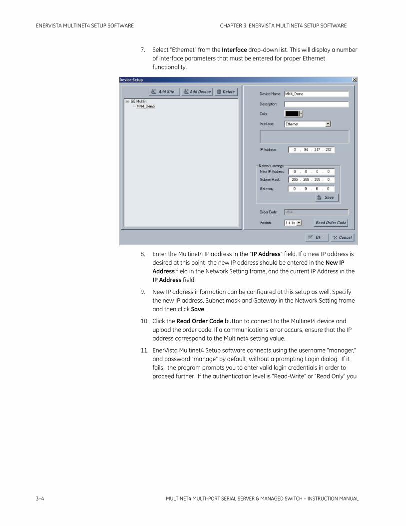
3–4 MULTINET4 MULTI-PORT SERIAL SERVER & MANAGED SWITCH – INSTRUCTION MANUAL
ENERVISTA MULTINET4 SETUP SOFTWARE CHAPTER 3: ENERVISTA MULTINET4 SETUP SOFTWARE
7. Select “Ethernet” from the Interface drop-down list. This will display a number of interface parameters that must be entered for proper Ethernet functionality.
8. Enter the Multinet4 IP address in the “IP Address” field. If a new IP address is desired at this point, the new IP address should be entered in the New IP Address field in the Network Setting frame, and the current IP Address in the IP Address field.
9. New IP address information can be configured at this setup as well. Specify the new IP address, Subnet mask and Gateway in the Network Setting frame and then click Save.
10. Click the Read Order Code button to connect to the Multinet4 device and upload the order code. If a communications error occurs, ensure that the IP address correspond to the Multinet4 setting value.
11. EnerVista Multinet4 Setup software connects using the username "manager," and password "manage" by default, without a prompting Login dialog. If it fails, the program prompts you to enter valid login credentials in order to proceed further. If the authentication level is "Read-Write" or "Read Only" you

CHAPTER 3: ENERVISTA MULTINET4 SETUP SOFTWARE ENERVISTA MULTINET4 SETUP SOFTWARE
MULTINET4 MULTI-PORT SERIAL SERVER & MANAGED SWITCH – INSTRUCTION MANUAL 3–5
will not be able to see port settings in the online tree. However you can still access the device through the Settings > Advanced Settings window of the online device in the Setup Software.
Note The login credentials policy is also applied when using Quick Connect, while saving settings to switch from Online configuration screens, while saving settings from offline file to online switch using “Write Settings File to Device”, while reading settings from online switch to offline file using “Read Device Settings”, firmware upload and Configure I/P features.
12. Click OK when the Multinet4 order code has been received. The new device will be added to the Site List window (or Online window) located in the top left corner of the main EnerVista Multinet4 Setup window.
The Site Device has now been configured for Ethernet communications. Proceed to the Connecting to the Multinet4 to begin communications.

3–6 MULTINET4 MULTI-PORT SERIAL SERVER & MANAGED SWITCH – INSTRUCTION MANUAL
ENERVISTA MULTINET4 SETUP SOFTWARE CHAPTER 3: ENERVISTA MULTINET4 SETUP SOFTWARE
3.4 Using the Quick Connect Feature
If you need to start talking to a Multinet4 device quickly, Press the Quick Connect button, to start the Quick Connect.
1. Click the Quick Connect button to open the Quick Connect dialog box.
2. Enter the IP address assigned to the Multinet4, then click Connect .
3. When Quick Connect device is added, it gets added under already existing first site. If no site exists, then a new site “Quick Connect Site” will be created and “Quick Connect Device” gets added under “Quick Connect Site”. Expand the sections to view data directly from the Multinet4 device.
4. Each time the EnerVista Multinet4 Setup software is initialized, click the Quick Connect button to establish direct communications to the Multinet4. This ensures that configuration of the EnerVista Multinet4 Setup software matches the Multinet4 device model number.

CHAPTER 3: ENERVISTA MULTINET4 SETUP SOFTWARE ENERVISTA MULTINET4 SETUP SOFTWARE
MULTINET4 MULTI-PORT SERIAL SERVER & MANAGED SWITCH – INSTRUCTION MANUAL 3–7
3.5 Connecting to the Multinet4
1. After Device Setup or Quick Connect completed, a site list tree will show on the left side of the EnerVista Multinet4 Setup window.
2. In this example, Ethernet port setting window will open by clicking the Ethernet under Setting > Ports as shown below:
3. The Ethernet window will open with a status indicator on the lower left of the EnerVista Multinet4 Setup window.
4. If the status indicator is red, verify that the Ethernet network cable is properly connected to the Ethernet port of the Multinet4 and that the IP address on both sides has been properly setup for communications (steps described earlier).
Note Please refer to the EnerVista Multinet4 Setup Help File for more information about the use of the EnerVista Multinet4 Setup software interface.

3–8 MULTINET4 MULTI-PORT SERIAL SERVER & MANAGED SWITCH – INSTRUCTION MANUAL
ENERVISTA MULTINET4 SETUP SOFTWARE CHAPTER 3: ENERVISTA MULTINET4 SETUP SOFTWARE
3.6 Port Setting
Ethernet port setting:
1. Ethernet setting window will open by clicking the Ethernet under Setting > Ports as shown below.
2. The system IP address, subnet mask and gateway address of the Multinet4 can be configured on this screen.
Note The Multinet4 has to be re-configured in the device setup whenever the IP details are configured from Ethernet Setting screen)
3. Also the Media, Flow control, Link Loss Handling and the administrative state for each Ethernet ports can be configured on this screen.
4. Make sure to click the Save button to make the change permanently.
Note Please refer to Chapter 4 in this manual for advanced setting for Ethernet Ports.
Serial Port Setting:
1. Serial port setting window will open by clicking the Serial under Setting -> Ports as shown below.
2. The serial interface type and COM setting such as Baud Rate, DataBits, StopBits, Parity, and Flow Control for each serial port can be configured on this screen.
3. The Packet Character, Packet Time, Max packet size and Turnaround Time for each serial port can be configured on this screen.
4. Also, the Modbus TCP port number and administrative state for each serial port can be configured on this screen.
5. Make sure to click the Save button to make the change permanently.

CHAPTER 3: ENERVISTA MULTINET4 SETUP SOFTWARE ENERVISTA MULTINET4 SETUP SOFTWARE
MULTINET4 MULTI-PORT SERIAL SERVER & MANAGED SWITCH – INSTRUCTION MANUAL 3–9
Note Please refer to Chapter 4 in this manual for the advanced setting for Serial Ports.

3–10 MULTINET4 MULTI-PORT SERIAL SERVER & MANAGED SWITCH – INSTRUCTION MANUAL
ENERVISTA MULTINET4 SETUP SOFTWARE CHAPTER 3: ENERVISTA MULTINET4 SETUP SOFTWARE
3.7 Advanced Setting
The EnerVista Multinet4 Setup allow user to login the web interface of Multinet4 by clicking the Advance Setting through the Site List tree.
1. An embedded web browser window will open with a status indicator.
2. The Multinet4 Web Management Logon screen will appear as shown below.
3. Login with username manager, password manager.
Note Please refer to Chapter 4 in this manual for more information about using the Advanced Setting - Administrator interface.

CHAPTER 3: ENERVISTA MULTINET4 SETUP SOFTWARE ENERVISTA MULTINET4 SETUP SOFTWARE
MULTINET4 MULTI-PORT SERIAL SERVER & MANAGED SWITCH – INSTRUCTION MANUAL 3–11
3.8 Firmware Upgrade
The Enervista Multinet4 Setup software or the Web interface or CLI interface or can be used to upgrade the firmware for the Multinet4. The EnerVista Multinet4 Setup software is the preferred method because it is much less error prone.
1. Click on “Upgrade Firmware” under Maintenance through the Site List tree as shown below.
2. An Open File window will open to allow the user to browse and choose the new firmware binary file.
3. Choose the desired file and then click the Open button to continue.
4. The uploading status is showing with the progress bar on the bottom of the main window.
5. Wait until this process complete and then click the Quick Connect to refresh the firmware revision.
Note • Please refer to Chapter 4 Administration Tasks section for more Information about firmware upgrade from the Web Administration Interface.[Please refer to Chapter 5 for more Information about firmware upgrade from the CLI Interface.]

3–12 MULTINET4 MULTI-PORT SERIAL SERVER & MANAGED SWITCH – INSTRUCTION MANUAL
ENERVISTA MULTINET4 SETUP SOFTWARE CHAPTER 3: ENERVISTA MULTINET4 SETUP SOFTWARE
3.9 Off-line Feature
The EnerVista Multinet4 Setup software interface supports three ways of handling changes to device settings:
• In off-line mode (device disconnected) to create or edit device settings files for later download to communicating devices.
• While connected to a communicating Multinet4 to directly modify any device settings via device data view windows, and then save the settings to the device.
• You can create/edit settings files and then write them to the device while the interface is connected to the device.
The Off-Line Window located underneath the On-Line Window, allows you to create, edit and save settings in a file (*.xml). The Off-Line Window is an Off-Line feature, meaning that direct communication with a Multinet4 device is enabled only when writing settings files to that Multinet4 device. The Off-Line Window supports the following operations of setting files:
• Add Existing Settings File
• New Settings File
• Remove File From List
• Edit Settings File Properties
• Duplicate Settings File
Settings files are organized on the basis of file names assigned by the user. A settings file contains data pertaining to the following types of Multinet4 settings:
• Device definition
• Settings
Note Please refer to the EnerVista Multinet4 Setup Help File for more information about the use of Off-Line Feature.
3.9.1 Reading Device SettingsThe EnerVista Multinet4 Setup program enables the reading of all programmed settings of a Multinet4 device provided that the device is On-line and successfully communicating. These settings can then be saved as a settings file in the Off-Line Window.
To Read the Settings of an On-line Device:
Select the Multinet4 device whose settings will be read from the Site List.
Right click within the On-Line Window to display the pop-up menu, and select the Read Device Settings option.
A Select Target File window will appear listing all, if any, target settings files in the Settings List Control Bar. Any one of these files may be selected to receive the settings that will be read from the Multinet4 device. If you choose to select one of these files, all previously saved settings will be overwritten by the Multinet4 device’s settingsIf no target settings files are available, then click the browse button and search your disk

CHAPTER 3: ENERVISTA MULTINET4 SETUP SOFTWARE ENERVISTA MULTINET4 SETUP SOFTWARE
MULTINET4 MULTI-PORT SERIAL SERVER & MANAGED SWITCH – INSTRUCTION MANUAL 3–13
files for a previously created EnerVista Multinet4 Setup file with the extension XML as the desired target. If no settings files have been previously created, then create a Settings List File.
Once a Target or Disk settings file has been selected to receive the Multinet4 device’s settings, click the Receive button. The EnerVista Multinet4 Setup program will read the settings of the Multinet4 and store them in the selected target settings file.
3.9.2 Writing Settings to a DeviceBefore writing to a Multinet4 device is possible, a settings file (*.xml) must be created, or an existing settings file must be selected from the Settings List tree directory.To Write a Settings File to a Device:
Choose a desired settings file from the Setting List directory under Offline windows.
Select Write Settings to Device either from the menu of main window or right click Mouse on the desired settings file in the Off-Line Window
Select Write Settings to Device from the Settings List Pop-Up Menu
A Select Target Device window will appear.
Select the desired target device.
Click Send. The EnerVista Multinet4 Setup program will now download the ENTIRE selected Settings file to the selected Multinet4 Target Device.
If your Multinet4 device is On-line and successfully communicating, all previously stored, device settings will be overwritten once the Send button is clicked.
If IP address is modified, you have to re-configure the online device using the Device Setup feature.

3–14 MULTINET4 MULTI-PORT SERIAL SERVER & MANAGED SWITCH – INSTRUCTION MANUAL
ENERVISTA MULTINET4 SETUP SOFTWARE CHAPTER 3: ENERVISTA MULTINET4 SETUP SOFTWARE
3.10 Configure a New IP Address through Console Port
The Multinet4 Serial Port Server is delivered with a default IP address 192.168.1.2. The user must change this address to one that is valid on the user’s network. The Multinet4 Setup software provides a way to configure a new IP through the Multinet4’s Console Port.
Before starting, the user has to connect one of serial port on the PC to the Console port on the Multinet4 device by a null modem serial cable. (See your Installation Guide for details.)
Click the Configure IP under the Communication menu, a pop-up window will appear.
Choose the correct COM port of your PC that you use to connect to the console port on the Multinet4.
Press the Connect button to read the original IP information of the Multinet4 device. The original IP address, subnet mask and gateway will appear on corresponding fields if communicating with Multinet4 through serial port successfully.
Specify the new IP address, subnet mask and gateway and then press Save button to configure this information to the Multinet4. If any of the details are not saved, they will change to existing values in Multinet4
Press the Connect button to read the IP information again to verify if the configuration has been done successfully.

MULTINET4 MULTI-PORT SERIAL SERVER & MANAGED SWITCH – INSTRUCTION MANUAL 4–1
Multinet4 Multi-Port Serial Server & Managed Switch
Chapter 4: System Administration
Digital EnergyMultilin
System Administration
This chapter describes the specific functionality of the Multinet4’s supervisory software.
For an overview of the interface features see section 2.7: The Advanced Setting - Administrator Interface Overview. For a list of all the available screens organized by function see section 2.7.3: The Administrator Interface Navigation Tree.
4.1 Virtual Front Panel
The Virtual Front Panel is displayed when you log on to Multinet4.
This screen provides an animated pseudo-real-time view of the device’s ports and LEDs. The status of the ports and LEDs is updated once per second.
The table locates beneath the graphical depiction of the front panel, provides a summary of information related to identifying the device (name, location, address) as well as the current uptime. Thse fields are read-only. To modify any of the user-configurable parameters, go to the appropriate editable screen. For instance, to change the system IP address, go to the screen described in section 4.6.1: Settings.

4–2 MULTINET4 MULTI-PORT SERIAL SERVER & MANAGED SWITCH – INSTRUCTION MANUAL
SYSTEM ADMINISTRATION CHAPTER 4: SYSTEM ADMINISTRATION
4.2 Administration Tasks
The following subsections describe the tasks that you can perform using the screens of the Administration branch.
4.2.1 SystemYou can view identifying information about your system in the System Information screen and monitor system status in the System Status screen, both shown below.
4.2.2 System InformationThis screen enables you to view and edit information that identifies the system under management.
FIGURE 4–1: Administration: System: Information
The table below describes the information that can be entered in the fields of the System Information screen. Each field can contain up to 256 printable ASCII characters.
Table 4–1: System Information
Field Name Field Value
System Name: Configurable MIB-II system name of up to 256 printable characters.
System Location: Configurable MIB-II system location of up to 256 printable characters.

CHAPTER 4: SYSTEM ADMINISTRATION SYSTEM ADMINISTRATION
MULTINET4 MULTI-PORT SERIAL SERVER & MANAGED SWITCH – INSTRUCTION MANUAL 4–3
4.2.3 System StatusThis screen enables you to view system status information.
FIGURE 4–2: Administration: System: Status
The table below describes the fields displayed in the System: Status screen.
System Contact: Configurable MIB-II system contact of up to 256 printable characters.
System Description: The system model number and current software version.
Upgrade State: The current software upgrade state.
IP Address: The system IP address. This may be changed from the 4.6.1
Settings screen.
MAC Address: The System MAC Address. This address is defined at the factory. You cannot change this address. All packets sourced from the management and terminal server functions use this MAC address as the Ethernet Source Address (SA). The system will also respond to ARP requests using this MAC address.
Free Space (KB): Number of KB free in the non-volatile file system.
Uptime: The time elapsed since the last system boot.
Table 4–1: System Information
Field Name Field Value

4–4 MULTINET4 MULTI-PORT SERIAL SERVER & MANAGED SWITCH – INSTRUCTION MANUAL
SYSTEM ADMINISTRATION CHAPTER 4: SYSTEM ADMINISTRATION
4.2.4 TimeThe following screens enable you to configure and preserve accurate time on your system.
4.2.4.1 Time: Time and Date
This screen allows you to configure the system time and date.
FIGURE 4–3: Administration: Time: Time and Date
The table below specifies the values that can be entered in the Time and Date screen.
Note the following features of the time and date functionality:
• When the system is first powered up, the time and date is undefined.
• The Multinet4 has an onboard RTC with a full battery backup.The RTC will preserve the current time and date for the life of the battery.
Table 4–2: System: Status
Field Name Field Value
System Memory Utilization: The percentage of dynamic system memory currently in use.
Ethernet-CPU Buffer Utilization: The software maintains a fixed size queue of buffers for received ethernet frames. This parameter is the percentage of these buffers currently holding a received frame that has not yet been processed by the IP stack or other network application.
Ethernet-CPU Rx Drops: The number of ethernet frames that were dropped due to queue overflow.
Table 4–3: Time and Date
Field Name Field Value
Time: The current time of day in the 24-hour hh:mm:ss format.
Date: The current date in the format mm/dd/yyyy.

CHAPTER 4: SYSTEM ADMINISTRATION SYSTEM ADMINISTRATION
MULTINET4 MULTI-PORT SERIAL SERVER & MANAGED SWITCH – INSTRUCTION MANUAL 4–5
• If SNTP is enabled and a server is reachable, the system time and date will be refreshed from the server upon power up.
4.2.4.2 Time: Zone and DST
This screen enables you to specify the standard time for your location as an offset from Universal Coordinated Time (UTC) and to specify the part of the year during which Daylight Savings Time (DST) will be in effect.
FIGURE 4–4: Administration: Time: Zone and DST

4–6 MULTINET4 MULTI-PORT SERIAL SERVER & MANAGED SWITCH – INSTRUCTION MANUAL
SYSTEM ADMINISTRATION CHAPTER 4: SYSTEM ADMINISTRATION
The table below describes the parameters you can view and edit in the Time: Zone and DST screen.
4.2.4.3 Time: Persistence
This screen enables you to set the time and date persistence feature (similar to the “Save Time Interval” feature offered by other manufacturers). This is used to support systems that do not have a clock with battery backup. When the power to these systems is cycled, the clock may come up in an undefined state. With persistence enabled the clock is set to the last known good time and date. This time and date clearly will not be correct but is likely to be close enough to the actual time and date that the system will be able to continue operating without difficulty.
This feature is useful in an environment where a Multinet4 keeps its time and date current via an NTP server that it accesses through a VPN tunnel that uses certificates for authentication. If the power to the Multinet4 is cycled and the time and date were to come up in an undefined state, it is likely that the VPN authentication would fail because the system's time and date would not match the valid dates on the VPN peer certificate. The system would then not be able to access the NTP server and would be permanently cut off
Table 4–4: Time: Zone and DST
Field Name Field Value
Standard Time=UTC: Your offset from the UTC. Value is in hours:minutes. Range is from -12:59 to 12:59
Daylight Saving Time: In enabled use the following fields to specify the period of the year during which daylight saving time will be in effect either by specifying the date and time of its beginning and end or by selecting a pre-defined national DST rule, which will automatically supply the beginning and ending values. System time will be automatically adjusted according to the specified dates.If disabled standard time will be used throughout the year.
Starts the first...: Specify the day, date, and time when DST begins.
Ends the first...: Specify the day, date, and time when DST ends.
Copy DST rule of: Select a pre-defined national DST rule from the drop-down list. This will automatically supply the beginning and ending values.
Examples: UTC Offsets
Zone Standard Daylight Saving
Eastern (US) -5 -4
Pacific (US) -8 -7
UK 0 +1

CHAPTER 4: SYSTEM ADMINISTRATION SYSTEM ADMINISTRATION
MULTINET4 MULTI-PORT SERIAL SERVER & MANAGED SWITCH – INSTRUCTION MANUAL 4–7
from the network. However, if the time and date were set to some time and date from the recent past, the VPN authentication would succeed, the tunnel would be established, and the Multinet4 would be able to resynchronize its time with the NTP server.
FIGURE 4–5: Administration: Time: Persistence
The table below specifies the parameter that you can set in the Time: Persistence screen.
4.2.5 SNTPThe SNTP (Simple Network Time Protocol) screens enable you to maintain the correct time on your system by specifying and configuring SNTP servers.
4.2.5.1 SNTP: Global Settings
This screen enables you to configure Simple Network Time Protocol (SNTP) functionality to obtain the correct time from an SNTP server.
FIGURE 4–6: Administration: SNTP: Global Settings
The table below specifies the values that can be entered in the fields of the SNTP: Global Settings screen to set up the SNTP client.
Table 4–5: Time: Persistence
Field Name Field Value
Mode: Set to Enabled to use the persistence feature.

4–8 MULTINET4 MULTI-PORT SERIAL SERVER & MANAGED SWITCH – INSTRUCTION MANUAL
SYSTEM ADMINISTRATION CHAPTER 4: SYSTEM ADMINISTRATION
If multiple SNTP servers are configured, the device will attempt to query the first SNTP server address. If the query is successful, it will acquire the time from that SNTP server. If the query is unsuccessful it will try the second configured server. If that is unsuccessful it will try the third. At the next polling interval, the device will again attempt to query the first SNTP server, followed by the second if necessary, then the third if necessary.
4.2.5.2 SNTP: Servers
This screen allows you to add and delete SNTP servers.
FIGURE 4–7: Administration: SNTP: Servers
Table 4–6: SNTP Global Settings
Field Name Field Value
Mode: Indicates if and how the SNTP client should be used to set the system's time and date information.This parameter takes one of the following values:
• Active – system time and date information is taken from a configured SNTP server.
• Passive – system time and date information is retrieved from SNTP information that is broadcast periodically from an SNTP server.
• Disabled – SNTP will not be used to acquire the current time.
Polling Interval: The frequency in seconds at which the SNTP server will be accessed to obtain the correct time when Active mode is selected.Default value = 60 (poll once per minute)Valid Range = 16 - 16384

CHAPTER 4: SYSTEM ADMINISTRATION SYSTEM ADMINISTRATION
MULTINET4 MULTI-PORT SERIAL SERVER & MANAGED SWITCH – INSTRUCTION MANUAL 4–9
The table below describes the fields of the SNTP: Servers screen to add and delete SNTP servers.
4.2.6 SNMPThe SNMP (Simple Network Management Protocol) screens enable you to specify up to four SNMP management stations and to maintain and view information in the system’s MIB (Management Information Base). For more information see 6.2: SNMP.
4.2.6.1 SNMP: Global Settings
The “SNMP: Global Settings” screen enables you to set up the system’s SNMP V1/V2 or V3 agent.
FIGURE 4–8: Administration: SNMP: Global Settings
Table 4–7: SNTP Servers
Field Name Field Value
Add Server Form
Server IP: Enter the IP address of an SNTP server to be accessed. Click Apply Settings to add this server to the Existing SNTP Servers Table.Up to 3 servers may be added. If a server is down, the software will try the next configured server when retrieving the current time and date.
Existing Servers Table
Server IP: Lists the IP address of any SNTP servers already configured.
Delete: Set the Delete checkbox in a row and click Apply Settings to delete that server.

4–10 MULTINET4 MULTI-PORT SERIAL SERVER & MANAGED SWITCH – INSTRUCTION MANUAL
SYSTEM ADMINISTRATION CHAPTER 4: SYSTEM ADMINISTRATION
The table below describes the parameters you can view and configure in the “SNMP: Global Settings” screen.
Table 4–8: SNMP: Global Settings
Field Name Field Value
Mode: Enable or disable SNMP agent.
• Disabled – agent does not respond to queries.
• V1/V2 Enabled – agent only responds to v1 or v2c PDUs.
• V3 Enabled – agent only responds to v3 PDUs.
Default value = Disabled
Write Access: Enable or disable write access to the MIB.
• Disabled – agent does not allow write access to the MIB.
• Enabled – agent allows write access to the MIB.
Default value = Disabled
Traps: Enable or disable the sending of traps to configured trap stations. Traps are event notifications sent by the agent to a trap station.
• Disabled – agent does not send traps to the configured trap stations.
• Enabled – agent sends traps to the configured trap stations.
Default value = Disabled
Read Community String: An arbitrary text string of up to 15 printable ASCII characters. The community string sent by the SNMP client must match this text for the MIB to be accessible for reading.
Write Community String:
An arbitrary text string of up to 15 printable ASCII characters. The community string sent by the SNMP client must match this text for the MIB to be accessible for writing.
Engine ID: A unique identifier assigned to this SNMP agent. You can configure an engine ID that is a string 32 characters long. If you do not configure an engine ID a 12-byte string will be assigned as the default ID. The default ID is a unique value combining the enterprise ID followed by MAC address or IP Address or plain text. The default engine ID for a Multinet4 device is as follows:
• The first four octets of the Enterprise ID(39cd).
• The fifth octet is a format identifier, which is 03 for MAC address.
• Six to eleven octets of MAC address.
• The remainder (up to the twelfth octet) is filled by zeroes.

CHAPTER 4: SYSTEM ADMINISTRATION SYSTEM ADMINISTRATION
MULTINET4 MULTI-PORT SERIAL SERVER & MANAGED SWITCH – INSTRUCTION MANUAL 4–11
4.2.6.2 SNMP: Management Stations
The “SNMP: Management Stations” screen enables you to configure SNMP management stations.
FIGURE 4–9: Administration: SNMP: Management Stations
The table below describes the parameters you can view and configure in the “SNMP: Management Stations” screen.
Engine Boots: The number of times the system has booted since the current engine ID was set.
Engine Time: The number of seconds elapsed since the engine ID was changed or the system booted, whichever occurred most recently.
Table 4–9: SNMP: Management Stations
Field Name Field Value
Add Station Form
IP Address: Enter the IP address of a management station that are allowed to query the SNMP agent. Click Apply Settings to add this address to the Existing Stations table.You can specify up to four management stations.
Table 4–8: SNMP: Global Settings
Field Name Field Value

4–12 MULTINET4 MULTI-PORT SERIAL SERVER & MANAGED SWITCH – INSTRUCTION MANUAL
SYSTEM ADMINISTRATION CHAPTER 4: SYSTEM ADMINISTRATION
4.2.6.3 SNMP: Trap Stations
This screen enables you add trap stations (up to a total of 4) and to view and edit the parameters of existing trap stations. A trap station is a destination to which SNMP traps are sent.
FIGURE 4–10: Administration: SNMP: Trap Stations
The table below describes the parameters you can view and edit in the SNMP: Trap Stations screen.
Existing Stations Table
IP Address: This table lists the IP addresses of management stations that have been configured in the system.
Delete: Set the Delete checkbox in a row and click Apply Settings to delete that management station.
Table 4–10: SNMP: Trap Stations
Field Name Field Value
IP Address: The Internet Protocol address of the trap station. You can specify up to 4 trap stations.
Table 4–9: SNMP: Management Stations
Field Name Field Value

CHAPTER 4: SYSTEM ADMINISTRATION SYSTEM ADMINISTRATION
MULTINET4 MULTI-PORT SERIAL SERVER & MANAGED SWITCH – INSTRUCTION MANUAL 4–13
4.2.6.4 SNMP: Users
This screen enables you to view and edit SNMP security provisions for individual users.
FIGURE 4–11: Administration: SNMP: Users
The table below specifies the parameters you can view and edit in the SNMP: Users screen.
Security Name: When the agent is enabled for v3 mode this is the name of an SNMP user. The trap will be sent with security mode and auth/priv passwords of that user. For v2 mode this is the trap community string for the trap destination.
Delete: Set the Delete checkbox in a row and click Apply Settings to delete that trap station.
Table 4–10: SNMP: Trap Stations
Field Name Field Value
Table 4–11: SNMP: Users
Field Name Field Value
User Name: A unique security name for an SNMP user.
Security Mode: level of security that the user is allowed. There are five types of security:
• None – No authentication or encryption
• MD5 – MD-5 authentication, no encryption
• SHA – SHA-1 authentication, no encryption
• MD5-DES – MD-5 authentication, DES encryption
• SHA-DES – SHA-1 authentication, DES encryption

4–14 MULTINET4 MULTI-PORT SERIAL SERVER & MANAGED SWITCH – INSTRUCTION MANUAL
SYSTEM ADMINISTRATION CHAPTER 4: SYSTEM ADMINISTRATION
Auth Password: Enter a password to be used for generating the authentication keys. Allowed password length is 8 to 40 characters.
Retype Password: Re-type the authentication password to confirm it.
Privacy Password: Enter a password to be used for generating the encryption keys. Allowed password length is 8 to 40 characters.
Retype Password: Re-type the privacy password to confirm it.
Delete: Set the Delete checkbox in a row and click Apply Settings to delete that user.
Table 4–11: SNMP: Users
Field Name Field Value

CHAPTER 4: SYSTEM ADMINISTRATION SYSTEM ADMINISTRATION
MULTINET4 MULTI-PORT SERIAL SERVER & MANAGED SWITCH – INSTRUCTION MANUAL 4–15
4.2.6.5 SNMP: Statistics
This screen below allows you to view detailed SNMP performance statistics.
FIGURE 4–12: Administration: SNMP: Statistics
The table below describes the values you can view in the SNMP: Statistics screen.

4–16 MULTINET4 MULTI-PORT SERIAL SERVER & MANAGED SWITCH – INSTRUCTION MANUAL
SYSTEM ADMINISTRATION CHAPTER 4: SYSTEM ADMINISTRATION
Table 4–12: SNMP: Statistics
Field Name Field Value
In Packets: The total number of messages delivered to the SNMP entity from the transport service.
Bad Versions: The total number of SNMP messages which were delivered to the SNMP protocol entity and were for an unsupported SNMP version.
In Bad Community Names:
The total number of SNMP messages delivered to the SNMP protocol entity which used an SNMP community name not known to the entity.
In Bad Community Uses:
The total number of SNMP messages delivered to the SNMP protocol entity which represented an SNMP operation not allowed by the SNMP community named in the message.
In ASN Parse Errors: The total number of ASN.1 or BER errors encountered by the SNMP protocol entity when decoding received SNMP Messages.
Enable Auth Traps: Indicates whether the SNMP agent process is permitted to generate authentication-failure traps. The value of this object overrides any configuration information; thus, it provides a means whereby all authentication-failure traps may be disabled.
Out Packets: The total number of SNMP Messages which were passed from the SNMP protocol entity to the transport service.
In Bad Types: The total number of SNMP PDUs which were delivered to the SNMP protocol entity and for which the value of the error-status field is “badType.”
In Too Bigs: The total number of SNMP PDUs which were delivered to the SNMP protocol entity and for which the value of the error-status field is “tooBig.”
Out Too Bigs: The total number of SNMP PDUs which were generated by the SNMP protocol entity and for which the value of the error-status field is “tooBig.”
In No Such Names: The total number of SNMP PDUs which were delivered to the SNMP protocol entity and for which the value of the error-status field is “noSuchName.”
Out No Such Names: The total number of SNMP PDUs which were generated by the SNMP protocol entity and for which the value of the error-status is “noSuchName.”
In Bad Values: The total number of SNMP PDUs which were delivered to the SNMP protocol entity and for which the value of the error-status field is “badValue.”

CHAPTER 4: SYSTEM ADMINISTRATION SYSTEM ADMINISTRATION
MULTINET4 MULTI-PORT SERIAL SERVER & MANAGED SWITCH – INSTRUCTION MANUAL 4–17
Out Bad Values: The total number of SNMP PDUs which were generated by the SNMP protocol entity and for which the value of the error-status field is “badValue.”
In Read Onlys: The total number valid SNMP PDUs which were delivered to the SNMP protocol entity and for which the value of the error-status field is “readOnly.”
Out Read Onlys: The total number valid SNMP PDUs which were generated by the SNMP protocol entity and for which the value of the error-status field is “readOnly.”
In Gen Errors: The total number of SNMP PDUs which were delivered to the SNMP protocol entity and for which the value of the error-status field is “genErr.”
Out Gen Errors: The total number of SNMP PDUs which were generated by the SNMP protocol entity and for which the value of the error-status field is “genErr.”
In Get Requests: The total number of SNMP Get-Request PDUs which have been accepted and processed by the SNMP protocol entity.
Out Get Requests: The total number of SNMP Get-Request PDUs which have been generated by the SNMP protocol entity.
In Get Nexts: The total number of SNMP Get-Next PDUs which have been accepted and processed by the SNMP protocol entity.
Out Get Nexts: The total number of SNMP Get-Next PDUs which have been generated by the SNMP protocol entity.
In Set Requests: The total number of SNMP Set-Request PDUs which have been accepted and processed by the SNMP protocol entity.
Out Set Requests: The total number of SNMP Set-Request PDUs which have been generated by the SNMP protocol entity.
In Get Responses: The total number of SNMP Get-Response PDUs which have been accepted and processed by the SNMP protocol entity.
Out Get Responses: The total number of SNMP Get-Response PDUs which have been generated by the SNMP protocol entity.
In Traps: The total number of SNMP Trap PDUs which have been accepted and processed by the SNMP protocol entity.
Out Traps: The total number of SNMP Trap PDUs which have been generated by the SNMP protocol entity.
In Total Req Vars: The total number of MIB objects which have been retrieved successfully by the SNMP protocol entity as the result of receiving valid SNMP Get-Request and Get-Next PDUs.
Table 4–12: SNMP: Statistics
Field Name Field Value

4–18 MULTINET4 MULTI-PORT SERIAL SERVER & MANAGED SWITCH – INSTRUCTION MANUAL
SYSTEM ADMINISTRATION CHAPTER 4: SYSTEM ADMINISTRATION
In Total Set Vars: The total number of MIB objects which have been altered successfully by the SNMP protocol entity as the result of receiving valid SNMP Set-Request PDUs.
Silent Drops: The total number of GetRequest PDUs, GetNextRequest PDUs,GetBulkRequest PDUs, SetRequest PDUs, and InformRequest PDUs delivered to the SNMP entity which were silently dropped because the size of a reply containing an alternate Response PDU with an empty variable-bindings field was greater than either a local constraint or the maximum message size associated with the originator of the request.
Proxy Drops: The total number of GetRequest PDUs, GetNextRequest PDUs,GetBulkRequest PDUs, SetRequest PDUs, and InformRequest PDUs delivered to the SNMP entity which were silently dropped because the transmission of the (possibly translated) message to a proxy target failed in a manner (other than a time-out) such that no Response PDU could be returned.
Unknown Security Models:
The total number of packets received by the SNMP engine which were dropped because they referenced a securityModel that was not known to or supported by the SNMP engine.
Invalid Messages: The total number of packets received by the SNM engine which were dropped because there were invalid or inconsistent components in the SNMP message, for example, noauth/priv. Multinet4 allows noauth/nopriv, auth/nopriv, and auth/priv but does not allow noauth/priv.
Unknown Contexts: The total number of packets received by the SNMP engine which were dropped because the context contained in the message was unknown.
Unavailable Contexts: The total number of packets received by the SNMP engine which were dropped because the context contained in the message was unavailable.
Unknown PDU Handlers:
The total number of packets received by the SNMP engine which were dropped because the PDU contained in the packet could not be passed to an application responsible for handling the pduType, for example, no SNMP application had registered for the proper combination of the contextEngineID and the pduType.
Unsupported Security Levels:
The total number of packets received by the SNMP engine which were dropped because they requested a securityLevel that was unknown to the SNMP engine or otherwise unavailable.
Table 4–12: SNMP: Statistics
Field Name Field Value

CHAPTER 4: SYSTEM ADMINISTRATION SYSTEM ADMINISTRATION
MULTINET4 MULTI-PORT SERIAL SERVER & MANAGED SWITCH – INSTRUCTION MANUAL 4–19
4.2.7 AuthenticationThe authentication screens enable you to set system-wide security policies, to add or delete user accounts, and to maintain user account information.
4.2.7.1 Authentication: Policies
The Authentication “Policies” form enables you to change the number of failed login attempts to allow before a user is locked out.
FIGURE 4–13: Administration: Authentication: Policies
The table below describes the parameters you can configure in configuring authentication security policies.
Not In Time Windows: The total number of packets received by the SNMP engine which were dropped because they appeared outside of the authoritative SNMP engine's window.
Unknown Usernames: The total number of packets received by the SNMP engine which were dropped because they referenced a user that was not known to the SNMP engine.
Unknown Engine IDs: The total number of packets received by the SNMP engine which were dropped because they referenced an snmpEngineID that was not known to the SNMP engine.
Wrong Digests: The total number of packets received by the SNMP engine which were dropped because they didn't contain the expected digest value.
Decryption Errors: The total number of packets received by the SNMP engine which were dropped because they could not be decrypted.
Table 4–12: SNMP: Statistics
Field Name Field Value

4–20 MULTINET4 MULTI-PORT SERIAL SERVER & MANAGED SWITCH – INSTRUCTION MANUAL
SYSTEM ADMINISTRATION CHAPTER 4: SYSTEM ADMINISTRATION
Note Violations of security settings such as: failed login attempts or inactive user expiration result in a "lock out" state. Only administrators may clear this state.
Table 4–13: Authentication: Policies
Field Name Field Value
Bad login attempts before lockout:
The number of consecutive failed login attempts before a user is locked out. A user is locked out by setting the Locked Out? field in the user's account to “Yes"Valid range = 1-5Default value = 5
Lockout Time: The amount of time a user account spends in the suspended state after being locked out. This parameter takes the following values:
• 5 minutes (default)
• 30 minutes
• 1 hour
Enforce Secure Passwords:
Setting this value to 'Yes' forces password changes to comply to the following standards:
• Length of 8 characters minimum
• Must consist of at least 2 of the 3 character types *
AlphabeticNumericPrintable Special characters
Default value = No*Spaces are not allowed in any password, regardless of this setting.

CHAPTER 4: SYSTEM ADMINISTRATION SYSTEM ADMINISTRATION
MULTINET4 MULTI-PORT SERIAL SERVER & MANAGED SWITCH – INSTRUCTION MANUAL 4–21
Password Ageing (Days):
Newly created accounts that are not part of the administration group can optionally expire passwords by setting this value to the number of days a password is valid before a change is required. Accounts that attempt to log in prior to the expiration date may change the password to reset the counter. Accounts that exceed this setting without a password change will be forced to change the password prior to accessing any other configuration screens. Valid settings for this option are:
• None
• 30 Days
• 60 Days
• 90 Days
Default value = NoneExisting accounts will start the password ageing on the login attempt after this change is made.
Inactive User Expiration (Days):
Newly created accounts that are not part of the administration group can optionally expire logins that are inactive exceeding the value specified here.A setting of 0 (default) disables this feature, otherwise the number of days of inactivity before being locked out ranges from 1 to 255.Existing accounts will start the user expiration on the login attempt after this change is made.
Table 4–13: Authentication: Policies
Field Name Field Value

4–22 MULTINET4 MULTI-PORT SERIAL SERVER & MANAGED SWITCH – INSTRUCTION MANUAL
SYSTEM ADMINISTRATION CHAPTER 4: SYSTEM ADMINISTRATION
4.2.7.2 Authentication: Accounts
The Authentication “User Accounts” enables an administrator to add and delete users and to maintain certain account information.
FIGURE 4–14: Administration: Authentication: Accounts
By factory default, there is a single administrator account with the login name “manager” and password “manager”. The Authentication: Accounts screen is available only to the administrator.
The table below describes the parameters you can configure in creating a new account or editing an existing account.
Table 4–14: Authentication: Accounts
Field Name Field Value
Add/Edit User Account(s) Forms
User ID: A unique ID for a user. This read-only value is assigned by the system.
Login Name: The name associated with this account. It must be entered along with the password in order to access the system’s user interface.Note that each login name on a given Multinet4 device must be unique.

CHAPTER 4: SYSTEM ADMINISTRATION SYSTEM ADMINISTRATION
MULTINET4 MULTI-PORT SERIAL SERVER & MANAGED SWITCH – INSTRUCTION MANUAL 4–23
Group Name: Use the drop-down list to assign this user to one of three privilege levels. The privilege levels are:
• Admin: Members of this group may perform all functions including managing software, user accounts, and configuration files.
• Read-Write: Members of this group may perform all configuration functions with the exception of software, user account, and configuration file management.
• Read-Only: Members of this group are like Read-Write except they cannot change any parameters.
Suspended?: This flag determines whether or not a user is allowed to log in to the system. The suspended flag may be set or cleared at any time by an administrator.
Locked Out? This flag also determines whether or not a user is allowed to log in to the system. The “Locked Out?” flag is set and cleared by the system based on the failed login attempts policy. This flag may also be manually cleared by an administrator. Unlike the “Suspended?” flag, it is not stored in non-volatile memory and therefore its state does not persist across resets.
Password: The password associated with this account. To create or change an account’s password enter the new password here. Characters in the password are always echoed back as the bullet character ( ). The field length minimum is 6 alphanumeric characters.
Re-Type Password: Confirm the initial password entry by re-typing it in this field.
Administrative Notes:
This field contains arbitrary text up to 31 printable ASCII characters.
Delete: Set the Delete checkbox in a row and click Apply Settings to delete that account.
Table 4–14: Authentication: Accounts
Field Name Field Value

4–24 MULTINET4 MULTI-PORT SERIAL SERVER & MANAGED SWITCH – INSTRUCTION MANUAL
SYSTEM ADMINISTRATION CHAPTER 4: SYSTEM ADMINISTRATION
4.2.7.3 Authentication: Files
This page enables you to upload new user definitions.
FIGURE 4–15: Administration: Authentication: Files
Table 4–15: Authentication: Files
Field Name Field Value
Browse: To install a new user definition file:
1. Browse to a file on you local system, or enter the full path name of a user definition file.
2. Click Upload.
Uploading a new file will be successful if the following conditions are met:
1. The uploaded file contains valid XML formatting consisting of -
— Only one instance of the UserAccountTable tag
— Only one instance per tag in each UserAccountEntry
— Only one instance of each login
2. The number of users contained in the file does not exceed the maximum number of supported users.
3. Files containing no users are valid, the default login account will be created.
4. If more than 0 accounts are specified, at least one account in the new configuration file is an unsuspended administrator.

CHAPTER 4: SYSTEM ADMINISTRATION SYSTEM ADMINISTRATION
MULTINET4 MULTI-PORT SERIAL SERVER & MANAGED SWITCH – INSTRUCTION MANUAL 4–25
4.2.8 SessionsThe sessions screens enable you to set login session policies and to monitor active logins.
4.2.8.1 Sessions: Policies
This screen enables you to set up the system's session management policies.
FIGURE 4–16: Administration: Sessions: Polices
The table below describes the parameter you can configure in the Sessions: Polices screen.
4.2.8.2 Sessions: Active Logins
This screen enables you to view the active login sessions on the device.
FIGURE 4–17: Administration: Sessions: Active Logins
Table 4–16: Sessions: Policies
Field Name Field Value
Maximum Idle Time: The amount of time a user session may be idle before it is automatically deleted by the system. Possible values are:
• None (Sessions never time out)
• 5 minutes
• 30 minutes
• 1 hour
• 24 hours

4–26 MULTINET4 MULTI-PORT SERIAL SERVER & MANAGED SWITCH – INSTRUCTION MANUAL
SYSTEM ADMINISTRATION CHAPTER 4: SYSTEM ADMINISTRATION
The table below describes the information displayed in the Sessions: Active Logins screen.
4.2.9 Change PasswordThis screen enables you to change your password. The administrator can also change any user’s password from the Authentication: Accounts screen, described in Section 4.2.7.2: Authentication: Accounts.
FIGURE 4–18: Administration: Change Password
The table below describes the parameters you can configure in the Change Password screen.
Table 4–17: Sessions: Active Logins
Field Name Field Value
Session: A unique identifier for a session.
Username: The username that is logged in.
Client Host: The IP address of the remote client.
Login Time: The time at which the user logged in to the system.
Last Activity: The last time the user was active in the session.
Delete: Set the Delete checkbox in a row and click Apply Settings to disconnect that active session.Note: the last saved administrator account is always preserved.
Table 4–18: Change Password
Field Name Field Value
Old Password: Enter the old password.

CHAPTER 4: SYSTEM ADMINISTRATION SYSTEM ADMINISTRATION
MULTINET4 MULTI-PORT SERIAL SERVER & MANAGED SWITCH – INSTRUCTION MANUAL 4–27
4.2.10 Software UpgradeThe “Software Upgrade” screen enables you to perform software upgrades or to return to a previous software image.
Browse to a file on you local system, or enter the full path name of a software image.
Click Upload.
When the new image file is successfully uploaded it will appear in the “Existing Images” window as “New” and a “Ready to Upgrade” message will appear.
Click the Upgrade button.The system will reboot.
Reconnect your browser to the system and return immediately to the Administration: Software Upgrade window.
Click the Finalize button
Note Remember that a successful upgrade requires the clicking of three buttons: Upload, Upgrade, and after a reboot, Finalize. Because some time passes while the system reboots and you reconnect your browser it is easy to overlook the third step.
Don’t Forget to Finalize!
Password: Enter the new password here. Characters in the password are always echoed back as the bullet character ( ). The field length minimum is 6 alphanumeric characters.
Re-Type Password: Confirm the initial password entry by re-typing it in this field.
Table 4–18: Change Password
Field Name Field Value

4–28 MULTINET4 MULTI-PORT SERIAL SERVER & MANAGED SWITCH – INSTRUCTION MANUAL
SYSTEM ADMINISTRATION CHAPTER 4: SYSTEM ADMINISTRATION
Software Upgrade States
The figure and table below describe the entire software upgrade finite state machine.
FIGURE 4–19: Software Upgrade State Machine
Table 4–19: Upgrade States and User Actions
Event Description
New Software User copies a valid software image.
Reboot User reboots the system.
Upgrade User clicks Upgrade button.
Finalize User clicks Finalize button, approving upgrade.
Fallback User clicks the Fallback button.Next system reboot loads the Fallback image.
Retry User clicks the Retry button.

CHAPTER 4: SYSTEM ADMINISTRATION SYSTEM ADMINISTRATION
MULTINET4 MULTI-PORT SERIAL SERVER & MANAGED SWITCH – INSTRUCTION MANUAL 4–29
The figure below depicts an Administration: Software Upgrade window after a successful upgrade.
FIGURE 4–20: Administration: Software Upgrade
The table below describes the parameters you can view and configure in the Software Upgrade screen.
Table 4–20: Software Upgrade
Field Name Field Value
Install Form
File: To install a new software image:
1. Browse to a file on you local system, or enter the full path name of a configuration file.
2. Click Upload.
The system checks to make sure that the uploaded software is valid for this hardware and that it appears to be a good image (not corrupt). If it is valid, then:
1. The filename is added to the Existing Images Table and is given the designation “new” in the Use column.
2. The status reported in the Software Upgrade process state table is changed to “READY TO UPGRADE.”

4–30 MULTINET4 MULTI-PORT SERIAL SERVER & MANAGED SWITCH – INSTRUCTION MANUAL
SYSTEM ADMINISTRATION CHAPTER 4: SYSTEM ADMINISTRATION
The table below describes the options available to you depending on the State and Use of the software images.
The system will automatically reboot during the transition from UPGRADING to FALLBACK and the transition from READY TO UPGRADE to UPGRADING because a new software image needs to be loaded in order to complete these transitions.
Existing Images Table
Filename: This table displays either one or two filenames. If the value displayed in the Software Upgrade process state table is “INITIAL” then this is the initial software installation and only one filename is displayed. In all other cases two filenames are displayed.
Use: The values displayed in the Use column depend on the state of the system. (See Table 4–21:: Software Upgrade States.)
Software Upgrade Table
State: This field reports the state of the upgrade process.
Button: The buttons displayed below the State field enable you to initiate a change in the state of the software upgrade. The number and purpose of the buttons displayed depends on the state of the software.
Table 4–21: Software Upgrade States
State Button
INITIAL none
READY TO UPGRADE
Upgrade: Click this button to reboot the system and load the new image. (Note that an upgrade by any means other than clicking the Upgrade button in this screen will also result in the loading of the new image.)
UPGRADING Finalize: Click this button to approve the upgrade. (Note that if the system reboots for any reason while in the UPGRADING state it will fall back to the previous image.)
UPGRADED Fallback: Click this button to reboot with the previous image.
FALLBACK Retry: Click this button to attempt the upgrade process again (move to the READY TO UPGRADE state).
Table 4–20: Software Upgrade
Field Name Field Value

CHAPTER 4: SYSTEM ADMINISTRATION SYSTEM ADMINISTRATION
MULTINET4 MULTI-PORT SERIAL SERVER & MANAGED SWITCH – INSTRUCTION MANUAL 4–31
4.2.11 Configuration The Configuration: Files and the Configuration: Defaults screens shown below, allow you to make system-wide changes by installing a new system configuration file or by returning to factory defaults.
4.2.11.1 Configuration: Files
This screen enables you to install and manage configuration files.
When the system is shipped from the factory, it contains a single current configuration file with factory default values called "config0.xml". Subsequent configuration files will contain the administrator’s saved settings.
FIGURE 4–21: Administration: Configuration: Files
The table below describes the tasks you can perform in the Configuration Files screen.
Table 4–22: Configuration Files
Field Name Field Value
The Install Form
File: To install a configuration file:
1. Browse to a file on you local system, or enter the full path name of a configuration file.
2. Click Upload.
Browse: Browse to select a configuration file on your local system.
Upload: Click this button to make the file specified in pathname the “Current” configuration file. If the configuration is valid the system is reconfigured according to the contents of the file.

4–32 MULTINET4 MULTI-PORT SERIAL SERVER & MANAGED SWITCH – INSTRUCTION MANUAL
SYSTEM ADMINISTRATION CHAPTER 4: SYSTEM ADMINISTRATION
You may encounter error messages when creating or saving configuration files if the uploaded file:
• Specifies a version beyond the current software version.
• Specifies a model other than the current system.
• Contains syntactically invalid XML code.
• Has the same name as an existing file on the system.
4.2.11.2 Configuration: Defaults
This screen enables you to restore the system configuration to default values.
Note Default values do not necessarily mean "factory default" values. While most parameters will take on their factory defaults, the following exceptions apply:
• System IP Address and Mask – Set to the IP address/mask configured in the boot menu.
• Default Gateway – Set to the default gateway configured in the boot menu.
The Configurations Table
Filename: This column lists all configuration files present in the system.
Version: This value identifies the software version that was running when the system wrote this configuration file.
Fallback: “Yes” identifies the Fallback configuration file. This file is used to save a copy of the configuration during initialization when the software upgrade state is UPGRADING. The "Fallback" file is designated "Current" when you tell the system to go to the FALLBACK state of software upgrade.
Current: The selected radio button identifies the current configuration file This is the file to which the current configuration data is written when you save it . This is also the file used for configuration when the software starts up.
Delete: Set the Delete checkbox in a row in the Configurations table and click Apply Settings to delete that configuration file.
Table 4–22: Configuration Files
Field Name Field Value

CHAPTER 4: SYSTEM ADMINISTRATION SYSTEM ADMINISTRATION
MULTINET4 MULTI-PORT SERIAL SERVER & MANAGED SWITCH – INSTRUCTION MANUAL 4–33
FIGURE 4–22: Administration: Configuration: Defaults
Click the Restore button to restore system defaults.

4–34 MULTINET4 MULTI-PORT SERIAL SERVER & MANAGED SWITCH – INSTRUCTION MANUAL
SYSTEM ADMINISTRATION CHAPTER 4: SYSTEM ADMINISTRATION
4.2.12 System RebootThis Reboot screen enables you to shut down and restart the system.
FIGURE 4–23: Administration: System Reboot
Click the Reboot button to reset the system.
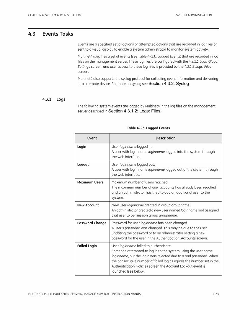
CHAPTER 4: SYSTEM ADMINISTRATION SYSTEM ADMINISTRATION
MULTINET4 MULTI-PORT SERIAL SERVER & MANAGED SWITCH – INSTRUCTION MANUAL 4–35
4.3 Events Tasks
Events are a specified set of actions or attempted actions that are recorded in log files or sent to a visual display to enable a system administrator to monitor system activity.
Multinet4 specifies a set of events (see Table 4–23:: Logged Events) that are recorded in log files on the management server. These log files are configured with the 4.3.1.1 Logs: Global Settings screen, and user access to these log files is provided by the 4.3.1.2 Logs: Files screen.
Multinet4 also supports the syslog protocol for collecting event information and delivering it to a remote device. For more on syslog see Section 4.3.2: Syslog.
4.3.1 LogsThe following system events are logged by Multinet4 in the log files on the management server described in Section 4.3.1.2: Logs: Files:
Table 4–23: Logged Events
Event Description
Login User loginname logged in.A user with login name loginname logged into the system through the web interface.
Logout User loginname logged out.A user with login name loginname logged out of the system through the web interface.
Maximum Users Maximum number of users reached.The maximum number of user accounts has already been reached and an administrator has tried to add an additional user to the system.
New Account New user loginname created in group groupname.An administrator created a new user named loginname and assigned that user to permission group groupname.
Password Change Password for user loginname has been changed.A user’s password was changed. This may be due to the user updating the password or to an administrator setting a new password for the user in the Authentication: Accounts screen.
Failed Login User loginname failed to authenticate.Someone attempted to log in to the system using the user name loginname, but the login was rejected due to a bad password. When the consecutive number of failed logins equals the number set in the Authentication: Policies screen the Account Lockout event is launched (see below).

4–36 MULTINET4 MULTI-PORT SERIAL SERVER & MANAGED SWITCH – INSTRUCTION MANUAL
SYSTEM ADMINISTRATION CHAPTER 4: SYSTEM ADMINISTRATION
Account Lockout Account loginname has been locked out for bad logins.A user account, with login name loginname, was suspended because the user entered a password incorrectly too many times in a row.
Lockout Ended Suspension timeout has elapsed for user loginname.A user who had been automatically suspended by the system for bad logins has been moved out of the locked out state by the system because the lockout timer (set in the Authentication: Policies screen) expired.
Suspension Cleared
Account lockout cleared for user loginname (UID nn).An administrator manually moved an account out of the suspended state.
Account Deleted User loginname (UID uid) was deleted.A user account was deleted by an administrator.
Expired Account User loginname expired.A user account expired due to inactivity (that is, no logins over a specified time period).
Suspended Account
User loginname was suspended.A user was suspended by an administrator.
Hacking Attempt Possible hacking attempt: n failed login attempts in m minutes.A number of unsuccessful logins have occurred within some time interval. This pattern is recognized by the system and logged as a warning to administrators.
Ethernet Link Up Ethernet port Ex is up.Link was detected on Ethernet port Ex.
Serial Link Up Serial port Sx is up.Link was detected on Serial port Sx.
Ethernet Link Down
Ethernet port Ex is down.Link was lost on Ethernet port Ex. This could be because the link was physically lost or because the port was administratively disabled.
Serial Link Down Serial port Sx is down.Link was lost on Serial port Sx. This could be because the RS-232 handshake signals are off or because the port was administratively disabled.
Unable to Connect
Could not connect to remote host ipaddr (tcpport) on channel Sx.The terminal server channel for Serial port Sx is configured to call out to a remote host at IP address ipaddr and TCP port tcpport , but that host is either unreachable or actively refused the connection.
Table 4–23: Logged Events
Event Description

CHAPTER 4: SYSTEM ADMINISTRATION SYSTEM ADMINISTRATION
MULTINET4 MULTI-PORT SERIAL SERVER & MANAGED SWITCH – INSTRUCTION MANUAL 4–37
Host Unreachable Serial port Sx reports that the host at ipaddr is unreachable.The terminal server channel for Serial port Sx is configured to call out to a remote host at IP address ipaddr but the system has no route to the destination address.
Connection Refused
Serial port Sx reports that the connection to the host at ipaddr (tcpport) was refused.The terminal server channel for Serial port Sx is configured to call out to a remote host at IP address ipaddr and TCP port tcpport , but the host actively refused the connection.
Lost Connection Lost connection with host ipaddr (tcpport) on channel Sx.The terminal server channel for Serial port Sx was connected but the system lost contact with the remote host. The remote host may have actively torn down the connection or the connection may have been flagged as dead due to lack of response to TCP keep-alive messages.
Handshake Failed Serial port Sx reports that the host at ipaddr (tcpport) did not respond to the SSL handshake.The terminal server channel for Serial port Sx is configured for SSL security. During the authentication phase of the SSL handshake, the peer did not respond. This is likely because the connection was made to a non-SSL enabled host.See the SSL troubleshooting section (Section 7.9: Troubleshooting Terminal Server SSL Connections) for more information.
Handshake Problem
Serial port Sx experienced a problem (problemdescription) while connecting to the host at ipaddr (tcpport).The terminal server channel for Serial port Sx is configured for SSL security. During the authentication phase of the SSL handshake, a problem occurred and the handshake did not complete. Possible problems include:
• unknown protocol
• no shared cipher
Table 4–23: Logged Events
Event Description

4–38 MULTINET4 MULTI-PORT SERIAL SERVER & MANAGED SWITCH – INSTRUCTION MANUAL
SYSTEM ADMINISTRATION CHAPTER 4: SYSTEM ADMINISTRATION
Certificate Problem
Serial port Sx reports that the certificate presented by the host at ipaddr (tcpport) was invalid (problemdescription).The terminal server channel for Serial port Sx is configured for SSL security. During the authentication phase of the SSL handshake, the peer certificate could not be validated. Possible reasons include:
• certificate expired
• certificate is not yet valid
• self signed certificate in certificate chain
See the SSL troubleshooting section (Section 7.9: Troubleshooting Terminal Server SSL Connections) for more information.
SSL Alert Message Serial port Sx received a notification (notification) from the host at ipaddr (tcpport).The terminal server channel for Serial port Sx is configured for SSL security. During the SSL handshake the peer detected a problem and sent an alert message. Possible alerts include:
• certificate expired
• certificate is not yet valid
• unknown ca
See the SSL troubleshooting section (Section 7.9: Troubleshooting Terminal Server SSL Connections) for more information.
RADIUS Server Unreachable
Unable to contact any of the configured RADIUS servers.The system is configured to contact a RADIUS server to perform user authentication but none of the configured servers are reachable over the network.
Boot Complete Warm start.The system rebooted.
SPD Packet Discard
Packet(s) discarded from not matching SPD rules. Check the source and destination IP address setup and tunnel state at both ends.
IKE Packet Discard
Packet(s) discarded due to tunnel Phase II incomplete. This state is usually temporary as the tunnel transitions to Phase II.
IKE Phase I Fail Phase I negotiation failed, most likely due to parameter mismatching of authentication or Diffie Hellman information.
IKE Phase I Success
IKE Phase 1 negotiation completed successfully
IKE Phase II Fail Phase II negotiation failed.
VPN Up IKE Phase 2 negotiation completed successfully and the tunnel is carrying traffic.
Table 4–23: Logged Events
Event Description

CHAPTER 4: SYSTEM ADMINISTRATION SYSTEM ADMINISTRATION
MULTINET4 MULTI-PORT SERIAL SERVER & MANAGED SWITCH – INSTRUCTION MANUAL 4–39
Sequence Number Overflow
IPsec sequence numbers have exceeded the boundary. This event is informational and should cause the tunnel to re-key.
Soft Life Time Expired
The soft life time for the tunnel has expired. The tunnel will re-key the next time a packet is received that must go through the tunnel. This is part of the normal operation of the tunnel.
Hard Life Time Expired
The hard lfe time for the tunnel has expired. The tunnel state will be deleted and must be re-negotiated.
Link Loss Alert Link Loss Alert on port Ex.The Link Loss Alert state machine triggered on port Ex and disabled the port’s transmitter.
Table 4–23: Logged Events
Event Description

4–40 MULTINET4 MULTI-PORT SERIAL SERVER & MANAGED SWITCH – INSTRUCTION MANUAL
SYSTEM ADMINISTRATION CHAPTER 4: SYSTEM ADMINISTRATION
4.3.1.1 Logs: Global Settings
This screen enables you to specify the frequency, number, and size of log files.
FIGURE 4–24: Events: Logs: Global Settings
The table below specifies the valid values for fields of the Logs: Global Settings form.
Table 4–24: Logs: Global Settings
Field Name Field Value
Mode: The available values are:
• Enabled – record events in the system log.
• Disabled – do not record events in the system log (default).
Create New Log File: Indicates how often a new log file should be started, regardless of the size of the current file. This parameter takes one of the following values:
• Daily: start a new log file at the beginning of each day (default).
• Weekly: start a new log file at the beginning of each week.
• Monthly: start a new log file at the beginning of each month.
When logging begins, a new file is created with the name “YYYYMMDDHHMMSS.log”.
Max Log Files: Specify the maximum number of log files to be preserved at any one time.Default value = 14.Valid range= 1-100

CHAPTER 4: SYSTEM ADMINISTRATION SYSTEM ADMINISTRATION
MULTINET4 MULTI-PORT SERIAL SERVER & MANAGED SWITCH – INSTRUCTION MANUAL 4–41
Use the Create New Log File, Max Log Files, Max Log File Size, and Delete Old Files parameters to structure your view of the history of events on the system. The total amount of available space on the system is now displayed on the 4.2.2 System Information screen.
Choose the values for these parameters based on the size of your system, the number of users, and the level of activity. This will take some experimentation. If, for instance, you want to create daily log files so that all the events for one 24-hour period will be included in a single file, it would be wise to specify a high Max Log File value at first, then observe the actual file size produced by routine operations and adjust the specification accordingly. Your observation of daily performance can be used as a basis for specifying the parameters appropriate to longer intervals; that is, a weekly log file ought to be have a Max Log File Size about seven times greater than that of a correctly-sized daily log file. When choosing the amount of space to allocate for logs keep in mind that space should be allowed for system files to grow (for example, software images, configuration files, PEM files, internal system files, etc.). We suggest allocating a maximum of 2 MB for logs.
Note that if you do not set the Delete Old Files to Yes (the default) Multinet4 will stop creating log files when the Max Log Files value is reached.
4.3.1.2 Logs: Files
This screen enables you to view a particular log by clicking on its hyperlinked file name. This will open the log file in the text editor configured for the .log suffix on your system. You can also delete a log file by checking the appropriate Delete box and pressing the Apply Settings button.
Max Log File Size (KB):
Specify the maximum size, in KB, of any log file. If the current log file becomes full, a new log file is created. Default value = 32KB.
Delete Old Files: Indicates whether or not old log files should be deleted when the maximum number of log files is reached and a new log file must be created. If you do not specify the deletion of old files no new log files will be created after the Max Log Files value is reached.Default value = Yes.
Table 4–24: Logs: Global Settings
Field Name Field Value

4–42 MULTINET4 MULTI-PORT SERIAL SERVER & MANAGED SWITCH – INSTRUCTION MANUAL
SYSTEM ADMINISTRATION CHAPTER 4: SYSTEM ADMINISTRATION
FIGURE 4–25: Events: Logs: Files
The table below explains how to use the fields in the Logs: Files table.
Log files are written as ASCII text in syslog format. For example:
<6>Jan 22 08:18:35 2007 192.168.1.2 Ethernet port E2 is down.<6>Jan 22 08:18:40 2007 192.168.1.2 Ethernet port E4 is up.<6>Jan 22 08:18:54 2007 192.168.1.2 Ethernet port E2 is up.<6>Jan 22 08:34:23 2007 192.168.1.2 User 'manager' logged in.<6>Jan 22 09:38:58 2007 192.168.1.2 User 'manager' idled out.
4.3.2 SyslogSyslog is a protocol for sending event messages over an IP network to remote servers called "event message collectors." The syslog protocol is defined in RFC 3164. You enable syslog functionality with the 4.3.2.1 Syslog: Global Settings screen, described in Section 4.3.2.1: Syslog: Global Settings. You specify the IP addresses of the remote devices that will serve as syslog collectors in the 4.3.2.2 Syslog: Collectors screen, described in Section 4.3.2.2: Syslog: Collectors. If syslog functionality is enabled, Multinet4 will
Table 4–25: Logs: Files
Field Name Field Value
Filename: The names and sizes of log files available for viewing. The log file that is currently active for writing is also flagged under the Status column. Click a hyperlinked file name to display a plain text version of the log file.
Delete: Set the Delete checkbox in a row and click Apply Settings to delete that log file.

CHAPTER 4: SYSTEM ADMINISTRATION SYSTEM ADMINISTRATION
MULTINET4 MULTI-PORT SERIAL SERVER & MANAGED SWITCH – INSTRUCTION MANUAL 4–43
deliver notification of syslog events to the specified collector(s). How that information is stored and displayed on the collector is a function of the software running on the collector. There are many freely available software products to manage this task.
4.3.2.1 Syslog: Global Settings
This screen enables you to enable syslog functionality.
FIGURE 4–26: Events: Syslog: Global Settings
Table 4–24:: Logs: Global Settings describes the parameter you can configure in the Syslog: Global Settings screen.
4.3.2.2 Syslog: Collectors
This screen enables you to specify the IP addresses of up to five syslog collectors.
FIGURE 4–27: Events: Syslog: Collectors
Table 4–26: Configure Syslog
Field Name Field Value
Mode: Indicates whether or not events should be sent as Syslog messages. The available values are:
• Enabled – Send a syslog message for each event.
• Disabled – Do not send syslog messages (default).

4–44 MULTINET4 MULTI-PORT SERIAL SERVER & MANAGED SWITCH – INSTRUCTION MANUAL
SYSTEM ADMINISTRATION CHAPTER 4: SYSTEM ADMINISTRATION
Table 4–24:: Logs: Global Settings describes the parameters you can edit in the Syslog: Collectors screen
Table 4–27: Syslog: Collectors
Field Name Field Value
Add Collector Form
Collector IP: The IP address of the server to which syslog messages will be sent.
Existing Collector Table
Collector IP: This column lists the addresses of existing configured collectors. The maximum number of collectors is 5. By default no collectors are configured.
Delete Set the Delete checkbox in a row and click Apply Settings to delete that collector.

CHAPTER 4: SYSTEM ADMINISTRATION SYSTEM ADMINISTRATION
MULTINET4 MULTI-PORT SERIAL SERVER & MANAGED SWITCH – INSTRUCTION MANUAL 4–45
4.4 Ethernet Tasks
The following subsections describe the tasks that you can perform using the screens of the Ethernet Switching branch.
4.4.1 PortsThe Ports screens enable you to configure ports and to view port status and statistics.
4.4.1.1 Ports: Settings
This screen enables you to configure the system’s Ethernet ports.
FIGURE 4–28: Ethernet: Ports: Settings
Table 4–28:: Ethernet: Ports: Settings describes the fields you can view and edit in the Ports: Settings form.
Table 4–28: Ethernet: Ports: Settings
Field Name Field Value
Port ID: Uniquely identifies a physical, labeled interface on the exterior of the product chassis. The Port ID string should exactly match the physical labeling scheme.
Port Name: A user-configurable name for the port. This may be any arbitrary text string up to 16 printable ASCII characters. This field is “Ethernet-X” by factory default.

4–46 MULTINET4 MULTI-PORT SERIAL SERVER & MANAGED SWITCH – INSTRUCTION MANUAL
SYSTEM ADMINISTRATION CHAPTER 4: SYSTEM ADMINISTRATION
Media Type: Enables you to force a speed and duplex setting on an Ethernet port or set the port to auto-negotiate mode. Only speed/duplex settings appropriate for the particular interface type are allowed:
• Auto (10/100BaseTX) (default for 10/100T)
• 10T Half (10/100BaseTX)
• 10T Full (10/100BaseTX)
• 100TX Half (10/100BaseTX)
• 100TX Full (10/100BaseTX)
• 100FX Full (100BaseFX) (default for 100FX)
Flow Control: This parameter applies to full duplex ports only. Flow control is optionally implemented using the 802.3x specification for PAUSE packets. When congested, the switch will send PAUSE packets to attached devices to request temporary suspension of transmission of further frames. The following values may be selected:
• Enabled
• Disabled
Default value = Disabled
Table 4–28: Ethernet: Ports: Settings
Field Name Field Value

CHAPTER 4: SYSTEM ADMINISTRATION SYSTEM ADMINISTRATION
MULTINET4 MULTI-PORT SERIAL SERVER & MANAGED SWITCH – INSTRUCTION MANUAL 4–47
Link Loss Handling: FEFI: When selected, this feature will send an alarm signal to the far-end transmitter of an optical port if the near-end receiver detects loss of signal. Also, if an alarm signal is received from a far-end transmitter, the near-end port will report its link status as down (even though it is receiving a good optical signal). The intent is to report a full duplex optical link as down even when a signal failure (for example, a fiber cut) occurs in only one direction. This is useful for automatic link recovery procedures. This parameter is ignored for copper ports.LLA: The GE Multilin Universal Relay (UR) family, and the F650 family of relays have redundant Ethernet ports that allow automatic switching to their secondary ports when they detect that the primary path is broken. The Multinet4 can compensate for situations where only the switch receiver fiber cable is broken. Upon detection of the broken receiver link, the Multinet4 will cease sending link pulses through the relay’s receive fiber cable, thereby allowing the relay to switch to its secondary path. It is recommended to enable the Link Loss Alert (LLA) feature on ports that are connected to end devices. LLA should be disabled for switch ports connected in a ring.
Admin Status: Enables you to set the activity status of the port. A setting of Disabled completely turns off the port’s transmit and receive functions. By factory default all ports except the last Ethernet port (E4 on the Multinet4) are disabled.The following values may be selected:
• Enabled
• Disabled
Default value = Enabled
Table 4–28: Ethernet: Ports: Settings
Field Name Field Value

4–48 MULTINET4 MULTI-PORT SERIAL SERVER & MANAGED SWITCH – INSTRUCTION MANUAL
SYSTEM ADMINISTRATION CHAPTER 4: SYSTEM ADMINISTRATION
4.4.1.2 Ports: Status
This screen enables you to quickly determine the capabilities and current status of each Ethernet port in the system.
FIGURE 4–29: Ethernet: Ports: Status
The table below describes the information displayed in the fields of the Ports: Status screen.
Table 4–29: Ethernet: Ports: Status
Field Name Field Value
Port ID: Uniquely identifies a logical Ethernet port that corresponds to a physical, labeled interface on the exterior of the product chassis.
Interface Type: A READ-ONLY field that indicates what interface is physically installed for the port specified in the Port ID column. This parameter is based on the product model and can be one of the following:
• 10/100BaseT
• 100BaseFX
Speed: A READ-ONLY field that indicates the actual speed of the communication channel. If you selected a particular Media Type in the 4.4.1.1 Ports: Settings screen the displayed speed will match that selection. If you selected “Auto” this field will display the actual negotiated speed. This parameter may take one of the following values:
• 10
• 100

CHAPTER 4: SYSTEM ADMINISTRATION SYSTEM ADMINISTRATION
MULTINET4 MULTI-PORT SERIAL SERVER & MANAGED SWITCH – INSTRUCTION MANUAL 4–49
4.4.1.3 Ports: Summary Statistics
This screen displays basic counters for each Ethernet port in the system. All of the statistics for a port are grouped into a table. You can reload the statistics by clicking the Refresh button.
The Summary Statistics screen is illustrated in the figure below.
FIGURE 4–30: Ethernet: Ports: Summary Statistics
Table 4–30:: Ethernet: Ports: Summary Statistics describes the parameters viewable in the Summary Statistics screens.
Duplex: A READ-ONLY field that indicates the actual duplex of the communication channel. If you selected a particular Media Type in the 4.4.1.1 Ports: Settings screen, the displayed duplex value will match that selection. If you selected “Auto” this field will display the actual negotiated duplex value. This parameter may take one of the following values:
• Half
• Full
Oper Status: A READ-ONLY field that indicates the current operational status of the port. This parameter may take one of the following values:
• Up – the port is enabled and a link is detected.
• Down – the port is enabled but there is no link.
• Disabled – the port is administratively disabled.
Table 4–29: Ethernet: Ports: Status
Field Name Field Value

4–50 MULTINET4 MULTI-PORT SERIAL SERVER & MANAGED SWITCH – INSTRUCTION MANUAL
SYSTEM ADMINISTRATION CHAPTER 4: SYSTEM ADMINISTRATION
4.4.1.4 Ports: Extended Statistics
To display this screen click a hyperlinked Port ID in the 4.4.1.3 Ports: Summary Statistics screen. The Extended Statistics screen displays a detailed set of counters for each Ethernet port in the system. The statistics may be re-loaded by clicking the Refresh button.
Table 4–30: Ethernet: Ports: Summary Statistics
Field Name Field Value
Port ID: Uniquely identifies an Ethernet interface.
Rx Packets: The total number of packets (including bad packets, broadcast packets, and multicast packets) received.
Rx Octets: The total number of octets of data (including those in bad packets) received on the network (excluding framing bits but including FCS octets).
Tx Packets: The total number of packets (including broadcast packets and multicast packets) transmitted.
Tx Octets: The total number of octets of data transmitted on the network (excluding framing bits but including FCS octets).
CRC Errors: The total number of packets received that had a length (excluding framing bits, but including FCS octets) of between 64 and 1518 octets, inclusive, but had a bad Frame Check Sequence (FCS) with an integral number of octets.
All Errors: The total number of errors detected

CHAPTER 4: SYSTEM ADMINISTRATION SYSTEM ADMINISTRATION
MULTINET4 MULTI-PORT SERIAL SERVER & MANAGED SWITCH – INSTRUCTION MANUAL 4–51
FIGURE 4–31: Ethernet: Ports: Extended Statistics
Table 4–30:: Ethernet: Ports: Summary Statistics describes the parameters viewable in both the Main and the Ports: Extended Statistics screens.
Table 4–31: Ethernet: Ports: Extended Statistics
Field Name Field Value
Rx Octets: The total number of octets of data (including those in bad packets) received on the network (excluding framing bits but including FCS octets).
Rx Packets: The total number of packets (including bad packets, broadcast packets, and multicast packets) received.
Rx Broadcast: The total number of good packets received that were directed to the broadcast address. Note that this number does not include packets directed to a multicast address.
Rx Unicast The total number of good packets received that were directed to a unicast address.

4–52 MULTINET4 MULTI-PORT SERIAL SERVER & MANAGED SWITCH – INSTRUCTION MANUAL
SYSTEM ADMINISTRATION CHAPTER 4: SYSTEM ADMINISTRATION
Rx Multicast: The total number of good packets received that were directed to a multicast address. Note that this number does not include packets directed to the broadcast address.
Rx Pause: Total number of PAUSE frames received.
Rx 64 Octets: The total number of packets (including bad packets) received that were exactly 64 octets in length (excluding framing bits but including FCS octets).
Rx 65 to127: The total number of packets (including bad packets) received that were between 65 and 127 octets in length inclusive (excluding framing bits but including FCS octets).
Rx 128 to 255: The total number of packets (including bad packets) received that were between 128 and 255 octets in length inclusive (excluding framing bits but including FCS octets).
Rx 256 to 511 The total number of packets (including bad packets) received that were between 256 and 511 octets in length inclusive (excluding framing bits but including FCS octets).
Rx 511 to1023: The total number of packets (including bad packets) received that were between 511 and 1023 octets in length inclusive (excluding framing bits but including FCS octets).
Rx1023 to Max: The total number of packets (including bad packets) received that were between 1024 and 1518 octets in length inclusive (excluding framing bits but including FCS octets).
Tx Octets: The total number of octets of data transmitted on the network (excluding framing bits but including FCS octets).
Tx Packets: The total number of packets (including broadcast packets and multicast packets) transmitted.
Tx Broadcast: The total number of packets transmitted that were directed to the broadcast address. Note that this number does not include packets directed to a multicast address.
Tx Unicast The total number of good packets transmitted that were directed to a unicast address.
Tx Multicast: The total number of packets transmitted that were directed to a multicast address. Note that this number does not include packets directed to the broadcast address.
Tx Pause: Total number of PAUSE frames transmitted.
Tx 64 Octets: The total number of packets transmitted that were exactly 64 octets in length (excluding framing bits but including FCS octets).
Table 4–31: Ethernet: Ports: Extended Statistics
Field Name Field Value

CHAPTER 4: SYSTEM ADMINISTRATION SYSTEM ADMINISTRATION
MULTINET4 MULTI-PORT SERIAL SERVER & MANAGED SWITCH – INSTRUCTION MANUAL 4–53
Tx 65to127: The total number of packets transmitted that were between 65 and 127 octets in length inclusive (excluding framing bits but including FCS octets).
Tx 128 to255: The total number of packets transmitted that were between 128 and 255 octets in length inclusive (excluding framing bits but including FCS octets).
Tx 256 to511: The total number of packets transmitted that were between 256 and 511 octets in length inclusive (excluding framing bits but including FCS octets).
Tx 51 to1023: The total number of packets transmitted that were between 511 and 1023 octets in length inclusive (excluding framing bits but including FCS octets).
Tx 1023 to Max: The total number of packets transmitted that were between 1023 and 1518 octets in length inclusive (excluding framing bits but including FCS octets).
CRC Errors: The total number of packets received that had a length (excluding framing bits, but including FCS octets) of between 64 and 1518 octets, inclusive but had a bad Frame Check Sequence (FCS) with an integral number of octets.
Alignment Errors: The total number of packets received that had a length (excluding framing bits, but including FCS octets) of between 64 and 1518 octets, inclusive but had a a bad FCS with a non-integral number of octets.
Undersized: The total number of packets received that were less than 64 octets long (excluding frame bits, but including FCS octets) and were otherwise well formed.
Oversized: The total number of packets received that were longer than 1518 octets (excluding frame bits, but including FCS octets) and were otherwise well formed.
Fragments: The total number of packets received that were less than 64 octets in length (excluding framing bits, but including FCS octets) and had either a bad FCS with an integral number of octets (FCS Error) or a bad FCS with a non-integral number of octets (Alignment Error).
Jabbers: The total number of packets received that were longer than 1518 octets (excluding framing bits, but including FCS octets), and had either a bad Frame Check Sequence (FCS) with an integral number of octets (FCS Error) or a bad FCS with a non-integral number of octets (Alignment Error).
Table 4–31: Ethernet: Ports: Extended Statistics
Field Name Field Value

4–54 MULTINET4 MULTI-PORT SERIAL SERVER & MANAGED SWITCH – INSTRUCTION MANUAL
SYSTEM ADMINISTRATION CHAPTER 4: SYSTEM ADMINISTRATION
4.4.1.5 Ports: Mirroring
This screen enables you configure Ethernet port mirrors. Port mirroring forwards a copy of each incoming and outgoing packet from one port of a Multinet4 to another port on the Multinet4, where the traffic can be monitored and/or analyzed.
FIGURE 4–32: Ethernet: Ports: Mirroring
The table below describes the parameters that can be viewed and edited in the Ports: Mirroring screen.
Filtered: The total number of valid frames received that are not forwarded to a destination port.
Discards: The total number of valid frames that were discarded due to lack of buffer space.
Collisions: The total number of collisions on this Ethernet segment.
Excessive: The total number of frames not transmitted because the frame experienced too many transmission attempts and was discarded.
Single: The total number of successfully transmitted frames that experienced exactly one collision.
Multiple: The total number of successfully transmitted frames that experienced more than one collision.
Late: The total number of times a collision is detected later than 512 bit-times into the transmission of a frame.
Deferred: The total number of successfully transmitted frames that are delayed because the medium was busy during the first attempt.
Table 4–31: Ethernet: Ports: Extended Statistics
Field Name Field Value

CHAPTER 4: SYSTEM ADMINISTRATION SYSTEM ADMINISTRATION
MULTINET4 MULTI-PORT SERIAL SERVER & MANAGED SWITCH – INSTRUCTION MANUAL 4–55
4.4.1.6 Ports: Rate Limits
Port Rate Limiting is supported on the Multinet4. This feature limits the ingress and egress throughput on a port. On ingress, various classes of packets can be limited. The user may choose to limit only broadcast packets, broadcast and multicast packets, all flooded packets (which includes unicast packets with destinations not found in the station cache), or all packets. On egress, all packet types are limited. Rate limits are configured as pre-defined values.
This screen enables you to view and edit the parameters that control port rate limits.
FIGURE 4–33: Ethernet: Ports: Rate Limits
The table below describes the parameters available in the Ethernet: Ports: Rate Limits screen.
Table 4–32: Ports: Mirroring
Field Name Field Value
Port ID: Uniquely identifies a logical Ethernet port that corresponds to a physical, labeled interface on the exterior of the product chassis. The Port ID string should exactly match the physical labeling scheme.
Copy to: Uniquely identifies the logical Ethernet port to which packets ingressing and egressing on this port will be copied.The default is "None," indicating that packets for the port are not copied to any other port.

4–56 MULTINET4 MULTI-PORT SERIAL SERVER & MANAGED SWITCH – INSTRUCTION MANUAL
SYSTEM ADMINISTRATION CHAPTER 4: SYSTEM ADMINISTRATION
4.4.2 BridgeThe Bridge screens enable you to configure and monitor Media Access Control (MAC) addresses.
There are two types of MAC addresses maintained by the bridge in its station cache:
Static – This is a MAC address that you enter and specify as entry type “Configured” in section 4.4.2.2 Bridge: Static MACs screen.
Dynamic – This is an address that is added to the station cache when the bridge detects a new address from a packet’s source address field. The bridge stores this address along with the ID of the port on which it was received. A learned address is maintained in the
Table 4–33: Ethernet: Ports: Rate Limits
Field Name Field Value
Port ID: Unique port identifier.
Ingress Limit Type: This parameter can take one of four parameters:
• Broadcast –
• Multicast –
• Flooded –
• All –
Ingress Rate (bps): This parameter can take one of eight parameters:
• Unlimited –
• 128K –
• 256K –
• 512K –
• 1M –
• 2M –
• 4M –
• 8M –
Egress Rate (bps): This parameter can take one of eight parameters:
• Unlimited –
• 128K –
• 256K –
• 512K –
• 1M –
• 2M –
• 4M –
• 8M –

CHAPTER 4: SYSTEM ADMINISTRATION SYSTEM ADMINISTRATION
MULTINET4 MULTI-PORT SERIAL SERVER & MANAGED SWITCH – INSTRUCTION MANUAL 4–57
station cache so long as it remains active in the system - a condition that is determined by the “aging interval.” For details see the 4.4.2.1 Bridge: Global Settings screen, and the 4.4.2.3 Bridge: Station Cache screen.
Learned – This is a static address that is learned by the bridge when address-based ethernet port security is enabled for a port. Once a static address has been learned for a secure port, the port will be disabled if frames sourced from any other MAC address are received. See the 4.8.2 Ethernet Port screen.
4.4.2.1 Bridge: Global Settings
This screen displays the aging interval applied to MAC addresses learned by the bridge and enables you to edit that setting.
FIGURE 4–34: Ethernet: Bridge: Global Settings
Table 4–34:: Ethernet: Bridge: Global Settings describes the parameter you can configure in the Ethernet: Bridge: Global Settings screen.
4.4.2.2 Bridge: Static MACs
The bridge station cache is a database that stores information about MAC addresses and their associated ports. This screen enables you to add the MAC addresses of stations to this cache or to remove them from the cache.
By factory default the static MAC address table is empty.
Table 4–34: Ethernet: Bridge: Global Settings
Field Name Field Value
Aging Interval: Entries (MAC addresses) learned by the bridge are deleted from the cache after they have been in the cache for the specified aging time without another packet arriving with the same source address. Default value = 300 seconds (5 minutes)Valid range = 15 seconds - 1,800 seconds (30 minutes)

4–58 MULTINET4 MULTI-PORT SERIAL SERVER & MANAGED SWITCH – INSTRUCTION MANUAL
SYSTEM ADMINISTRATION CHAPTER 4: SYSTEM ADMINISTRATION
FIGURE 4–35: Ethernet: Bridge: Static MACs
The table below describes the uses of the fields of the Bridge: Static MACs screen.
Table 4–35: Ethernet: Bridge: Static MACs
Field Name Field Value
Add Static MAC Address Form
Static Source Address:
Specify the static MAC Address of a station to add it to the bridge station cache.MAC addresses are entered in their hexadecimal representation. Each octet must be separated by a colon or a hyphen (e.g. 01-02-03-04-05-06 or 01:02:03:04:05:06).
Source Port: Select a “Source Port” designation from the drop-down menu.
Existing Static MAC Addresses Table
Static Source Address:
Lists the static MAC addresses already recognized in the system.
Source Port: Lists the source ports associated with static MAC addresses.
Entry Type: Indicates whether an entry in the table was configured by a user or learned by the MAC security feature.
Delete: Set the “Delete” checkbox in a row and click the Apply Settings button to delete the entry from the table and from the station cache.

CHAPTER 4: SYSTEM ADMINISTRATION SYSTEM ADMINISTRATION
MULTINET4 MULTI-PORT SERIAL SERVER & MANAGED SWITCH – INSTRUCTION MANUAL 4–59
4.4.2.3 Bridge: Station Cache
This screen enables you to view the station cache. The station cache is a database maintained by the Ethernet bridge that tracks MAC addresses of stations on the network and the ports associated with them. This form displays a snapshot of the contents of the Ethernet bridge station cache.
The cache can contain up to 1,024 random entries.
The only administrative action available on this screen is provided by the Purge Dynamic Entries button. You might want to purge these learned addresses if you make changes to the network that are completed before the configured aging interval. In such a case it could be true that the cache record of a port/station relationship could be incorrect from the time you complete your changes until the old information ages out with the expiration of the aging interval.
FIGURE 4–36: Ethernet: Bridge: Station Cache
The table below describes the uses of the fields and buttons in the Bridge: Station Cache screen.
Table 4–36: Bridge: Station Cache
Field Name Field Value
Source Address: IP address of a station known to be active in the system. An Ethernet packet that has a destination address that matches an entry in the table is forwarded out the interface shown in the Source Port column in the same row.

4–60 MULTINET4 MULTI-PORT SERIAL SERVER & MANAGED SWITCH – INSTRUCTION MANUAL
SYSTEM ADMINISTRATION CHAPTER 4: SYSTEM ADMINISTRATION
4.4.3 RSTPThe RSTP screens enable you to configure Rapid Spanning Tree Protocol (RSTP). For more on RSTP see 6.1.3.3: 802.1p-to-priority queue Mapping.
4.4.3.1 RSTP: Bridge Settings
This screen enables you to configure bridge-specific Rapid Spanning Tree Protocol (RSTP) settings.
FIGURE 4–37: Ethernet: RSTP: Bridge Settings
The table below describes the bridge parameters you can view and configure in the RSTP: Bridge Settings form.
Source Port: Identifies the port associated with the address in the Source Address column.
Entry Type: There are three entry types:
• Static – Entries that are set by the user. These are not removed automatically.
• Dynamic – Entries that are learned by the bridge. These are removed automatically from the cache if they are not refreshed in the "aging interval." (The aging interval is specified in the 4.4.2.1 Bridge: Global Settings screen).
• Learned – A static address that is learned by the bridge when address-based ethernet port security is enabled for a port. Once a static address has been learned for a secure port, the port will be disabled if frames sourced from any other MAC address are received. See the 4.8.2 Ethernet Portscreen for more information.
Table 4–36: Bridge: Station Cache
Field Name Field Value

CHAPTER 4: SYSTEM ADMINISTRATION SYSTEM ADMINISTRATION
MULTINET4 MULTI-PORT SERIAL SERVER & MANAGED SWITCH – INSTRUCTION MANUAL 4–61
Table 4–37: RSTP: Bridge Settings
Field Name Field Value
Protocol: Select whether or not to run the Spanning Tree Protocol. This parameter can take one of the following values:
• Enabled
• Disabled
Default value = disabled
Priority: Used by the IEEE 802.1d spanning tree algorithm to determine the root of the interconnected network. Bridge priority provides a means of assigning relative priority to each bridge within the set of bridges in the bridged LAN. Valid range = 0-65535Default value = 32768Numerically lower values indicate higher priorities.
Hello Time: The amount of time between the transmission of configuration BPDUs on any port.Valid range = 1-10 secondsDefault value = 2 seconds
Forward Delay: Controls how long the bridge waits after any state or topology change before forwarding the information to the network.Valid range = 4-30 secondsDefault value = 15 seconds
Maximum Age: Specifies the age of STP information learned from the network on any port before it is discarded.Valid range = 6-40 secondsDefault value = 20 seconds
Cost Style: Specifies whether 16-bit (STP-style) or 32-bit (RSTP-style) path cost values are used. This parameter can take one of the following values:
• 32-bit
• 16-bit
Default value = 16-bit

4–62 MULTINET4 MULTI-PORT SERIAL SERVER & MANAGED SWITCH – INSTRUCTION MANUAL
SYSTEM ADMINISTRATION CHAPTER 4: SYSTEM ADMINISTRATION
4.4.3.2 RSTP: Port Settings
This page enables you to configure port-specific Rapid Spanning Tree Protocol (RSTP) parameters.
FIGURE 4–38: Ethernet: RSTP: Port Settings
The table below describes the port parameters you can view and configure in the RSTP: Port Settings form.
Table 4–38: RSTP: Port Settings
Field Name Field Value
Port ID: Uniquely identifies an Ethernet interface.
Mode: The mode the switch will use on this port for RSTP operation. This parameter can take one of the following values:
• Legacy – The port uses STP only.
• Auto – The port automatically determines the correct mode based on received BPDUs.
• Edge – The port uses RSTP and is connected to an end system where no loops are possible.
• Point – The port uses RSTP and is connected to another switch (that runs RSTP) over a point-to-point link where loops may be possible.
Default value = Auto
Priority: The priority part of the port identifier. mode the switch will use on this port.Valid range = 0-255Default value = 128Numerically lower values indicate higher priorities.

CHAPTER 4: SYSTEM ADMINISTRATION SYSTEM ADMINISTRATION
MULTINET4 MULTI-PORT SERIAL SERVER & MANAGED SWITCH – INSTRUCTION MANUAL 4–63
4.4.3.3 RSTP: Bridge Status
This page enables you to view bridge-specific RSTP counters and status.
FIGURE 4–39: Ethernet RSPT: Bridge Status
The table below describes the bridge status and counters you can view in the RSTP: Bridge Status table.
Table 4–39: RSTP: Bridge Status
Field Name Field Value
Bridge Status: This parameter can take one of the following values:
• Root
• Designated
• Not Designated
Bridge ID: The bridge identifier, which consists of the bridge priority and the bridge address.
Root ID: The bridge identifier of the root.
Root Port: The Ethernet port that provides connectivity towards the root bridge for this network.
Root Path Cost: The total cost of the path to the root bridge. This is the summation of the costs of each link in the path to the root.
Configured Hello Time:
The locally configured Hello Time.

4–64 MULTINET4 MULTI-PORT SERIAL SERVER & MANAGED SWITCH – INSTRUCTION MANUAL
SYSTEM ADMINISTRATION CHAPTER 4: SYSTEM ADMINISTRATION
4.4.3.4 RSTP: Port Status
This page enables you to view port-specific RSTP counters and status.
The table below describes the port status and counters you can view in the RSTP: Port Status table.
Learned Hello Time: The actual Hello Time provided by the root bridge through configuration BPDUs.The learned Hello Time is used in all designated bridges.
Configured Forward Delay:
The locally configured Forward Delay.
Learned Forward Delay:
The actual Forward Delay provided by the root bridge through configuration BPDUs.The learned Forward Delay is used in all designated bridges.
Configured Maximum Age:
The locally configured Maximum Age.
Learned Maximum Age:
The actual Maximum Age provided by the root bridge through configuration BPDUs. The learned Maximum Age is used in all designated bridges.
Topology Changes: The total number of topology changes that have been detected by this bridge since the last time statistics were cleared, or since the device was powered on (whichever event is more recent).
Table 4–39: RSTP: Bridge Status
Field Name Field Value
Forwarding
Blocking
Blocking
Designated
Backup
Root
Alternate
200000 342 332 33 2
200000 11 2 311
200000
32 22 622
233 222 1 1
200000

CHAPTER 4: SYSTEM ADMINISTRATION SYSTEM ADMINISTRATION
MULTINET4 MULTI-PORT SERIAL SERVER & MANAGED SWITCH – INSTRUCTION MANUAL 4–65
4.4.4 VLANFor a discussion of VLAN configuration see 6.4.3: VLANs and Serial Ports.
4.4.4.1 VLAN: Global Settings
This screen enables you enable VLAN functionality on a switch.
FIGURE 4–40: Ethernet: VLAN: Global Settings
Table 4–40: RSTP: Port Status
Field Name Field Value
Port ID: Unique port identifier.
State: This parameter can take one of the following values:
• Disabled
• Blocking
• Forwarding
• Learning
• Listening
Role: This parameter can take one of the following values:
• Root
• Designated
• Backup
• Alternate
Cost: The cost metric associated with this port. This is automatically determined based on the speed of the interface and the configured cost style (32-bit or 16-bit).
Rx CFGs: The number of STP configuration BPDUs received on this port.
Rx TCNs: The number of STP TCNs (Topology Change Notifications) received on this port.
Rx RSTPs: The number of RSTP BPDUs received on this port.
Tx BPDUs: The number of BPDUs (STP or RSTP) transmitted on this port.

4–66 MULTINET4 MULTI-PORT SERIAL SERVER & MANAGED SWITCH – INSTRUCTION MANUAL
SYSTEM ADMINISTRATION CHAPTER 4: SYSTEM ADMINISTRATION
The table below describes the parameters you can view and configure in the VLANs: Global Settings screen.
4.4.4.2 VLAN: VIDs
This screen enables you to add and delete up to 16 VLAN IDs (VIDs). It also serves to show a summary of the VLAN configuration.
FIGURE 4–41: Ethernet: VLAN: VIDs
Table 4–41: VLANs: Global Settings
Field Name Field Value
Mode: Indicates whether or not the switch is VLAN-aware.
• Enabled – perform ethernet switching based on VLAN tags and configured port membership.
• Disabled – ignore VLAN tags and port memberships when performing Ethernet switching.
Default value = Disabled
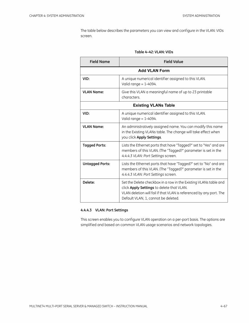
CHAPTER 4: SYSTEM ADMINISTRATION SYSTEM ADMINISTRATION
MULTINET4 MULTI-PORT SERIAL SERVER & MANAGED SWITCH – INSTRUCTION MANUAL 4–67
The table below describes the parameters you can view and configure in the VLAN: VIDs screen.
4.4.4.3 VLAN: Port Settings
This screen enables you to configure VLAN operation on a per-port basis. The options are simplified and based on common VLAN usage scenarios and network topologies.
Table 4–42: VLAN: VIDs
Field Name Field Value
Add VLAN Form
VID: A unique numerical identifier assigned to this VLAN. Valid range = 1-4094.
VLAN Name: Give this VLAN a meaningful name of up to 23 printable characters.
Existing VLANs Table
VID: A unique numerical identifier assigned to this VLAN. Valid range = 1-4094.
VLAN Name: An administratively assigned name. You can modify this name in the Existing VLANs table. The change will take effect when you click Apply Settings.
Tagged Ports: Lists the Ethernet ports that have "Tagged?" set to "Yes" and are members of this VLAN. (The “Tagged?” parameter is set in the 4.4.4.3 VLAN: Port Settings screen.
Untagged Ports: Lists the Ethernet ports that have "Tagged?" set to "No" and are members of this VLAN. (The “Tagged?” parameter is set in the 4.4.4.3 VLAN: Port Settings screen.
Delete: Set the Delete checkbox in a row in the Existing VLANs table and click Apply Settings to delete that VLAN. VLAN deletion will fail if that VLAN is referenced by any port. The Default VLAN, 1, cannot be deleted.

4–68 MULTINET4 MULTI-PORT SERIAL SERVER & MANAGED SWITCH – INSTRUCTION MANUAL
SYSTEM ADMINISTRATION CHAPTER 4: SYSTEM ADMINISTRATION
FIGURE 4–42: Ethernet: VLAN: Port Settings
The table below describes the VLAN parameters you can configure in the Port Settings form.
Table 4–43: VLAN: Port Settings
Field Name Field Value
Port ID: Unique identifier for this port.
PVID: This is the native VLAN assigned to this port. When the port receives an untagged frame, an 802.3ac VLAN tag is added to the frame using the port's PVID. When a port receives a tagged frame on an access port, the frame is discarded unless its VID matches the port's PVID. When a port receives a priority-tagged frame, the tag's VID is set to the port's PVID. Default value = 1.
Mode: This is the port type with respect to VLAN operation.
• An access port is typically connected to an end station and supports a single VLAN. When a port is set to Access mode, the "Prohibited VLANs" field (which only applies to Trunk ports) is disabled.
• A trunk port is typically connected to another switch and by default supports all configured VLANs. When a port is set to Trunk, the "Tagged?" field is automatically set to "Yes" and the "Prohibited VLANs" field is enabled.
Default value = Access

CHAPTER 4: SYSTEM ADMINISTRATION SYSTEM ADMINISTRATION
MULTINET4 MULTI-PORT SERIAL SERVER & MANAGED SWITCH – INSTRUCTION MANUAL 4–69
Tagged? The available options for this field have the following significance:
• No – the port strips all VLAN tags before transmitting frames.
• Yes – the port ensures that a VLAN tag is present in a frame before transmission.
Default value = No
Prohibited VLANs: This is a list of VLANs to prohibit from a Trunk port. By default, this field is blank and the port allows all configured VLANs. By setting the Prohibited VLANs list, the user can filter certain VLANs on the trunk. The Trunk's PVID is not allowed in the Prohibited VLANs list for the port. This field is disabled when the port mode is set to "Access".Enter the VID numbers of prohibited VLANs separated by commas. A continuous range of VIDs can be indicated by a dash. For example: 4, 6-8, 12, 15.
Table 4–43: VLAN: Port Settings
Field Name Field Value

4–70 MULTINET4 MULTI-PORT SERIAL SERVER & MANAGED SWITCH – INSTRUCTION MANUAL
SYSTEM ADMINISTRATION CHAPTER 4: SYSTEM ADMINISTRATION
4.5 Serial Tasks
The following subsections describe the tasks that you can perform using the screens of the Serial Tasks branch.
4.5.1 PortsThe Ports screens enable you to configure and monitor serial ports.
4.5.1.1 Ports: Profiles
This screen enables you to add and configure serial port profiles.
The Add New Profile Form enables you to add a new profile to the table of existing profiles. The values shown in the figure below, are the default values presented in this table when the page loads or re-loads. After setting the appropriate parameters and giving the profile a name, press the Apply Settings button and the profile is added to the Edit Existing Profiles table.
The Edit Existing Profiles table enables you to change one or more of the parameters in a profile. Each profile entry has a checkbox in the “Delete” column. You can delete one or more profiles by checking the appropriate box and pressing the Apply Settings button. You can make any number of changes to the table; however, none of these changes take effect until the Apply Settings button is pressed. Pressing the Reset Settings button will reset all modified fields to the value they had when the page originally loaded.
To supply the correct values for each of the parameters in the Profiles screen you need to know the specifications of the device with which each port will be communicating. This information can usually be found in the installation documentation of the communicating device.
Systems are shipped from the factory with a single default profile called “Default”.

CHAPTER 4: SYSTEM ADMINISTRATION SYSTEM ADMINISTRATION
MULTINET4 MULTI-PORT SERIAL SERVER & MANAGED SWITCH – INSTRUCTION MANUAL 4–71
FIGURE 4–43: Serial: Ports: Profiles
The table below describes the parameters in the Ports: Profiles screen.
Table 4–44: Ports: Profiles
Field Name Field Value
Profile Name: A user-assigned name for this profile. When you assign a profile to a port in the 4.5.1.2 Ports: Settings screen, you select this name in the “Profile” drop-down box.
Interface Standard: The physical interface standard used by the port. This parameter may take one of three values:
• RS-232 (RTS always asserted)
• RS-232 Half (RTS asserted only when transmitting)
• RS-485 2-wire (half duplex operation)
• RS-485 4-wire (full duplex operation)
Default value = RS-232WARNING: Make sure to configure the correct interface standard before connecting to the device. Improper setup can result in damage to the unit.

4–72 MULTINET4 MULTI-PORT SERIAL SERVER & MANAGED SWITCH – INSTRUCTION MANUAL
SYSTEM ADMINISTRATION CHAPTER 4: SYSTEM ADMINISTRATION
Speed: The baud rate of the port. This parameter may take one of the following values:
• 1200
• 2400
• 4800
• 9600
• 19200
• 28800
• 33600
• 38400
• 57600
• 115200
Default value = 9600
Data Bits: The total number of bits in a character. This parameter may take one of the following values:
• 7
• 8
Default value = 8
Stop Bits: The duration of the MARK condition on the line after character transmission is complete. This parameter may take one of the following values:
• 1
• 1.5
• 2
Default value = 1
Parity: This parameter may take one of the following values:
• None
• Even
• Odd
Default value = None
Table 4–44: Ports: Profiles
Field Name Field Value

CHAPTER 4: SYSTEM ADMINISTRATION SYSTEM ADMINISTRATION
MULTINET4 MULTI-PORT SERIAL SERVER & MANAGED SWITCH – INSTRUCTION MANUAL 4–73
Flow Control: The type of flow control implemented. This parameter may take one of the following values:
• None
• XON/XOFF – Software flow control. Unit will stop transmitting if an XOFF (19) character (CTL-S) is detected in the received stream and will start when an XON (17) character (CTL-Q) is detected.
• RTS/CTS – Hardware flow control. Unit will stop transmitting if CTS is de-asserted.
Default value = None
Ignore DSS: This parameter takes one of the following values:
• No: The Oper State of the port is UP if the DSR or DCD handshake signal is on and the Admin State is ENABLED.
• Yes: The Oper State of the port is UP if the Admin State is ENABLED
Default value = No
Pkt Char: This parameter defines a special character in the data stream that forces a packetization event. This parameter may take any value from 0 to 255. If this parameter is set to the label “None” packetization will not occur based on a received character. Default value = None
Pkt Time (ms): This parameter defines a timeout value in milliseconds. If an additional character is not received before the timer expires, a packetization event occurs. The special value 0 disables the packetization timer. Valid range = 10 msec to 1000 msec.Default value = 10
Max Pkt Size (bytes): This parameter defines a maximum packet size. When the number of received characters reaches this maximum, a packetization event occurs. Valid range = 32 to 1024. (Note that this means no packet will hold more than 1024 serial characters. The actual packet size will be larger than this when network headers and encryption overhead are taken into account.) Default value = 1024
Table 4–44: Ports: Profiles
Field Name Field Value

4–74 MULTINET4 MULTI-PORT SERIAL SERVER & MANAGED SWITCH – INSTRUCTION MANUAL
SYSTEM ADMINISTRATION CHAPTER 4: SYSTEM ADMINISTRATION
4.5.1.2 Ports: Settings
This Form enables you to set high-level configuration parameters for a serial port. Most of the low-level serial port configuration is contained in the profile which is selected for each port.(For more on profiles see 4.5.1.1 Ports: Profiles.
FIGURE 4–44: Serial: Ports: Settings
The table below describes the values in the fields of the Ports: Settings screen.
T/A Time (ms): This parameter defines a turnaround time for the serial port. The turnaround time is an enforced minimum delay between received network packets that are sent out the serial port. The purpose of the minimum delay is to give legacy RTUs a chance to recover from the previous packet reception. Default value = 0 (off)
Delete: Set the Delete checkbox in a row in the Edit Existing Profiles table and click Apply Settings to delete that profile.
Table 4–45: Ports: Settings
Field Name Field Value
Port ID: This value uniquely identifies a Serial interface.
Port Name: A user-assigned name for this port of up to 15 printable characters. This field is empty by factory default.
Table 4–44: Ports: Profiles
Field Name Field Value

CHAPTER 4: SYSTEM ADMINISTRATION SYSTEM ADMINISTRATION
MULTINET4 MULTI-PORT SERIAL SERVER & MANAGED SWITCH – INSTRUCTION MANUAL 4–75
4.5.1.3 Ports: Statistics
This screen displays counters for each Serial port in the system.
FIGURE 4–45: Serial: Ports: Statistics
The statistics for each port are grouped into separate rows. The “Last cleared” text under each table tells you when the counting of the displayed statistics began. All totals displayed are since the “Last cleared” date and time.
The table below describes the parameters displayed in the Ports: Statistics tables.
Profile: The serial profile assigned to this port. The assigned profile defines all of the communication parameters associated with this serial port. The default value is the default factory profile “Default”. Profiles are set in the 4.5.1.1 Ports: Profiles screen.
Admin Status: The desired status of the port. This parameter is used to enable or disable the port.This parameter can take the following values:
• Enabled – Port is UP
• Disabled – Port is DOWN
Default value = DisabledNote: The actual status of the port is reported in the Oper Status column of the 4.4.1.2 Ports: Status screen.
Table 4–46: Ports: Statistics
Field Name Field Value
Port ID: Uniquely identifies a Serial interface.
Tx Char: The number of characters transmitted on this port.
Rx Char: The number of characters received on this port.
Table 4–45: Ports: Settings
Field Name Field Value

4–76 MULTINET4 MULTI-PORT SERIAL SERVER & MANAGED SWITCH – INSTRUCTION MANUAL
SYSTEM ADMINISTRATION CHAPTER 4: SYSTEM ADMINISTRATION
Ports: Statistics Screen Controls
The Ports: Statistics screen includes the following controls for viewing, clearing, and updating statistics:
Refresh Button – Click this button to update the statistics.
Clear Counters Button – Click this button to zero out all counters. Counting will begin again and the “Last cleared” date and time will be refreshed.
4.5.2 Terminal ServerThe screens described in the following subsections enable you to configure and view your TCP/IP connections.
4.5.2.1 Terminal Server: Channel Settings
This screen enables you to configure the terminal server channel settings. For more on terminal server applications see section 7.1: What is a Terminal Server?
Breaks: The number of times a break was detected in the middle of receiving a character. A break is detected when an all-zero character with no stop bit is received.
Parity Errors: The number of times the calculated parity of a character did not match the configured parity mode. (Note: character will be dropped.)
Framing Errors: The number of times a character without a valid stop bit was detected.
Overruns: The number of times a received character was dropped because it could not be buffered.
Table 4–46: Ports: Statistics
Field Name Field Value

CHAPTER 4: SYSTEM ADMINISTRATION SYSTEM ADMINISTRATION
MULTINET4 MULTI-PORT SERIAL SERVER & MANAGED SWITCH – INSTRUCTION MANUAL 4–77
FIGURE 4–46: Serial: Terminal Server: Channel Settings
The Add New Channel Form is used to add new Terminal Server channels and to modify parameters for channels that have already been added to the system. Each channel has the capability to make a single outgoing connection and accept multiple incoming connections. By default, a single channel exists for each serial port.
Table 4–44:: Ports: Profiles shown above, describes the parameters in the Terminal Server: Channel Settings screen.

4–78 MULTINET4 MULTI-PORT SERIAL SERVER & MANAGED SWITCH – INSTRUCTION MANUAL
SYSTEM ADMINISTRATION CHAPTER 4: SYSTEM ADMINISTRATION
Table 4–47: Terminal Server: Channel Settings
Field Name Field Value
Port ID: A unique identifier for the serial port being configured.
Call Direction: The direction in which the TCP connection will be established. This parameter takes one of the following values:
• In: The port acts like a passive TCP server, listening at the configured Local TCP port.
• Out: The port acts like an active TCP client and attempts to connect out to the server specified by the Remote IP and Remote TCP parameters.
You can add multiple "Out" channels to a single serial port; however, you can have only a single "In" channel assigned to a serial port. You cannot assign two channels the same Local Address and Local Port.Default value = In
Session Type: This parameter takes one of the following values:
• Raw: Provides a transparent pipe for serial data.
• Telnet: Enables basic Telnet negotiation and control character processing (ECHO and BINARY modes supported).
Default value = Raw
Priority (DiffServ): Each IP packet generated on this port will be assigned a DiffServ Code Point (DSCP) based on the priority set by the user. The priorities are:
• Default – Best Effort Service (DSCP 0). This is normal queuing.
• Expedited – Expedited Forwarding (DSCP 0x2E) (RFC2598). This will also result in data from this port having a higher priority on WAN ports.
Local IP: The local IP address upon which the server listens for connections when the direction is set to “In” or “Both”. This parameter may be set to any of the valid IP addresses configured for the system. Default value = Management IP address of the device
Local TCP: The local TCP port upon which the server listens for connections. This parameter may be set to any value between 1000 and 65535.Note: No two rows in the table may have the same Local IP and Local TCP combination.

CHAPTER 4: SYSTEM ADMINISTRATION SYSTEM ADMINISTRATION
MULTINET4 MULTI-PORT SERIAL SERVER & MANAGED SWITCH – INSTRUCTION MANUAL 4–79
Remote IP: The remote IP address that the client attempts to connect to when the direction is set to “Out” or “Both”. This parameter may be set to any IP address. Default value = 0.0.0.0
Remote TCP: The remote TCP port to which the client attempts to connect. This parameter may be set to any value between 0 and 65535. Default value = 0
Max Conn: The maximum number of incoming TCP connections to accept for this serial port. This parameter may be set to a value ranging from 1 to 10. Default value = 5
Retry Time: The number of seconds the client waits for a connection to succeed before timing out and retrying.Default value = 30
Table 4–47: Terminal Server: Channel Settings
Field Name Field Value

4–80 MULTINET4 MULTI-PORT SERIAL SERVER & MANAGED SWITCH – INSTRUCTION MANUAL
SYSTEM ADMINISTRATION CHAPTER 4: SYSTEM ADMINISTRATION
4.5.2.2 Terminal Server: Channel Status
This screen enables you to view the current status of each Terminal Server Channel.
FIGURE 4–47: Serial: Terminal Server: Channels Status
The Terminal Server: Channel Status screen is similar to the 4.5.2.1 Terminal Server: Channel Settings screen. However, it displays two types of information not included in the Terminal Server screen: the state of each channel and the number of established connections. These two fields are explained in the table below. For explanations of the other fields in the Services: Channels screen see the description of the 4.5.2.1 Terminal Server: Channel Settings screen.

CHAPTER 4: SYSTEM ADMINISTRATION SYSTEM ADMINISTRATION
MULTINET4 MULTI-PORT SERIAL SERVER & MANAGED SWITCH – INSTRUCTION MANUAL 4–81
4.5.2.3 Terminal Server: Connections
This page displays the status of the current TCP/IP connections carrying serial traffic. The values displayed are a subset of the values that can be configured in the 4.5.2.1 Terminal Server: Channel Settings screen, but the Terminal Server: Connections screen is a read-only display of active TCP/IP connections.
FIGURE 4–48: Serial: Terminal Server: Connections
Table 4–48: Terminal Server: Channel Status
Field Name Field Value
State: The state of the channel. This field may display one of the following values:
• Inactive: The channel is disabled because the associated serial port is disabled or down.
• Listening: The channel is acting as a passive server and is waiting for incoming connection requests.
• Refusing: The channel is acting as a passive server and is actively refusing new connections because it has reached the maximum number of connections for the channel.
• Waiting: The channel is acting as an active client and is waiting for the re-try timer to expire. After the timer expires the channel will attempt again to establish the configured connection.
• Connecting: The channel is acting as an active client, has issued a connection request to the configured remote host, and is waiting for a response.
• Connected: The channel is acting as an active client and a connection has been established.
• Handshaking: The channel is associated with a secure serial port and is currently attempting an SSL handshake with the remote host.
Connections: The number of connections that have been established on this channel. For a client this is always 0 or 1. For a server it can be 0 up to the maximum number of connections allowed for that channel

4–82 MULTINET4 MULTI-PORT SERIAL SERVER & MANAGED SWITCH – INSTRUCTION MANUAL
SYSTEM ADMINISTRATION CHAPTER 4: SYSTEM ADMINISTRATION
The table below describes the parameters displayed in the Terminal Server: Connections screen.
4.5.3 ModbusModbus is a protocol, based on a master/slave architecture, for communication with industrial electronic devices. Use the following screens to configure and monitor Modbus masters and slaves. For more information see section 6.7: Modbus.
4.5.3.1 Global Settings
Allows the user to configure the system’s Modbus Management feature.
This screen is used to configure Modbus global settings. The parameters are defined as follows:
Table 4–49: Terminal Server: Connections
Field Name Field Value
Port ID: A unique identifier for this serial port.
Connection Type: Indicates whether or not the connection is encrypted and if so, which cipher is being used.
Session Type: This parameter can take one of the following values:
• Raw: Provides a transparent pipe for serial data.
• Telnet: Enables basic Telnet negotiation and control character processing (ECHO and BINARY modes supported).
• Default value = Raw
Local IP: The local IP address upon which the server listens for connections when the direction is set to “In” or “Both”.
Local TCP: The local TCP port upon which the server listens for connections.
Remote IP: The remote IP address that the client attempts to connect to when the direction is set to “Out” or “Both”.
Remote TCP: The remote TCP port to which the client attempts to connect
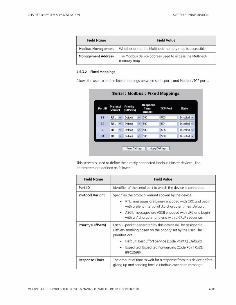
CHAPTER 4: SYSTEM ADMINISTRATION SYSTEM ADMINISTRATION
MULTINET4 MULTI-PORT SERIAL SERVER & MANAGED SWITCH – INSTRUCTION MANUAL 4–83
4.5.3.2 Fixed Mappings
Allows the user to enable fixed mappings between serial ports and Modbus/TCP ports.
This screen is used to define the directly connected Modbus Master devices. The parameters are defined as follows:
Field Name Field Value
Modbus Management Whether or not the Multinet4 memory map is accessible
Management Address The Modbus device address used to access the Multinet4 memory map
Field Name Field Value
Port ID Identifier of the serial port to which the device is connected.
Protocol Variant Specifies the protocol variant spoken by the device
• RTU: messages are binary encoded with CRC and begin with a silent interval of 3.5 character times (Default).
• ASCII: messages are ASCII encoded with LRC and begin with a ‘:’ character and end with a CRLF sequence.
Priority (DiffServ) Each IP packet generated by this device will be assigned a DiffServ marking based on the priority set by the user. The priorities are:
• Default: Best Effort Service (Code Point 0) (Default).
• Expedited: Expedited Forwarding (Code Point 0x2E) (RFC2598).
Response Timer The amount of time to wait for a response from this device before giving up and sending back a Modbus exception message.

4–84 MULTINET4 MULTI-PORT SERIAL SERVER & MANAGED SWITCH – INSTRUCTION MANUAL
SYSTEM ADMINISTRATION CHAPTER 4: SYSTEM ADMINISTRATION
4.5.3.3 Modbus: Local Masters
This screen enables you to configure local serial Modbus Masters that will act as Modbus/TCP clients.
FIGURE 4–49: Serial: Modbus: Local Masters
This screen is used to define the directly connected Modbus Master devices. The table below specifies the parameters you can edit in the Serial: Modbus: Local Masters screen.
TCP Port The TCP port upon which this serial port can be accessed. Be sure to disable the fixed mapping before swapping ports.
State Whether or not the fixed mapped TCP port is enabled
Table 4–50: Modbus: Local Masters
Field Name Field Value
Port ID: A unique identifier for the serial port to which the device is connected.
Protocol Variant: Specify a serial transmission mode. Valid options are:
• RTU – Messages are binary encoded with CRC and begin with a silent interval of 3.5 character times.
• ASCII – messages are ASCII encoded with LRC and begin with a ':' character and end with a CRLF sequence.
Default value = RTU
Field Name Field Value

CHAPTER 4: SYSTEM ADMINISTRATION SYSTEM ADMINISTRATION
MULTINET4 MULTI-PORT SERIAL SERVER & MANAGED SWITCH – INSTRUCTION MANUAL 4–85
4.5.3.4 Modbus: Local Slaves
This screen allows enables you to configure local serial Modbus Slaves that will be accessible via the Modbus/TCP server.
FIGURE 4–50: Serial: Modbus: Local Slaves
This screen is used to define the directly connected Modbus devices. The table below specifies the parameters you can view and edit in the Serial: Modbus: Local Slaves screen.
Priority (DiffServ): Each IP packet generated by this device will be assigned a DiffServ Code Point (DSCP) based on the priority set by the user. The priorities are:
• Default – Best Effort Service (DSCP 0). This is normal queuing.
• Expedited – Expedited Forwarding (DSCP 0x2E) (RFC2598). This will also result in data from this port having a higher priority on WAN ports.
Exception Support: Specify whether or not the attached master understands Modbus exception messages. In some cases Modbus devices do not support the exception function codes and will be confused by them if received. This option allows you to disable exception forwarding to the master device.
Delete: Set the Delete checkbox in a row in the Existing Devices table and click Apply Settings to delete that local master.
Table 4–50: Modbus: Local Masters
Field Name Field Value

4–86 MULTINET4 MULTI-PORT SERIAL SERVER & MANAGED SWITCH – INSTRUCTION MANUAL
SYSTEM ADMINISTRATION CHAPTER 4: SYSTEM ADMINISTRATION
4.5.3.5 Modbus: Remote Slaves
This screen enables you to configure the forwarding table used to map Modbus slave device addresses to remote IP addresses.
Table 4–51: Modbus: Local Slaves
Field Name Field Value
Port ID: A unique identifier for the serial port to which the device is connected.
Device Address: Modbus/TCP unit identifier assigned to the device.Valid range = 1-247
Protocol Variant: Specify a serial transmission mode. Valid options are:
• RTU – Messages are binary encoded with CRC and begin with a silent interval of 3.5 character times.
• ASCII – messages are ASCII encoded with LRC and begin with a ':' character and end with a CRLF sequence.
Default value = RTU
Priority (DiffServ): Each IP packet generated by this device will be assigned a DiffServ Code Point (DSCP) based on the priority set by the user. The priorities are:
• Default – Best Effort Service (DSCP 0). This is normal queuing.
• Expedited – Expedited Forwarding (DSCP 0x2E) (RFC2598). This will also result in data from this port having a higher priority on WAN ports.
Response Timer (msec):
The amount of time to wait for a response from this device before giving up and sending back a Modbus exception message.
Send Gateway Exceptions:
Specify whether or not to send exception codes. Possible values are:
• Yes – Send Modbus/TCP exception codes when an error occurs (for example, timeout).
• No – Remain silent when an error occurs.
Delete: Set the Delete checkbox in a row in the Existing Devices table and click Apply Settings to delete that local slave.

CHAPTER 4: SYSTEM ADMINISTRATION SYSTEM ADMINISTRATION
MULTINET4 MULTI-PORT SERIAL SERVER & MANAGED SWITCH – INSTRUCTION MANUAL 4–87
FIGURE 4–51: Serial: Modbus: Remote Slaves
This screen is used to add a mapping between a Modbus device address and the IP address of a remote Modbus/TCP server. The table below specifies the parameters you can view and edit in the Serial: Modbus: Remote Slaves screen.
Table 4–52: Modbus: Remote Slaves
Field Name Field Value
Device Address: Modbus/TCP unit identifier assigned to the remote device.Valid range = 1-247
Remote IP Address: The IP address of the remote Modbus/TCP server.
Idle Time (secs): The TCP connection for this device is torn down if the idle time (time between messages) exceeds the value specified here. This parameter allows multiple successive requests to the same remote device to re-use a single TCP connection, thereby reducing latency. As a special case, if this value is set to 0, a TCP connection is immediately made to the remote (that is, the client does not wait for a request) and it is always kept open. This special mode eliminates the connection latency associated with the initial Modbus request.
Response Time (msecs):
The client will wait this amount of time before giving up on a request. If the client times out, it closes down the current TCP connection for the remote device.
Delete: Set the Delete checkbox in a row in the Existing Devices table and click Apply Settings to delete that remote slave.

4–88 MULTINET4 MULTI-PORT SERIAL SERVER & MANAGED SWITCH – INSTRUCTION MANUAL
SYSTEM ADMINISTRATION CHAPTER 4: SYSTEM ADMINISTRATION
4.5.3.6 Modbus: Connections
This screen displays the status of all active Modbus/TCP connections. This table contains all of the active Modbus/TCP connections in the system and the traffic statistics associated with each connection. You can also manually disconnect any TCP connection by selecting the appropriate Delete checkbox and pressing the "Apply Settings" button.
FIGURE 4–52: Serial: Modbus: Connections
The table below describes the values you can view in the Serial: Modbus: Connections screen.
Table 4–53: Modbus: Connections
Field Name Field Value
Connection Mode: Indicates whether this connection was established in client or server mode.
Local Address: The IP address of the local Modbus/TCP client/server.
Local Port: The TCP port of the local Modbus/TCP client/server.
Remote Address: The IP address of the remote Modbus/TCP client/server.
Remote Port: The TCP port of the remote Modbus/TCP client/server.
Requests: The number of requests generated (if client) or number of requests received (if server).
Responses: The number of responses received (if client) or number of responses generated (if server).
Tx Octets: The total number of octets transmitted on this connection.
Rx Octets: The total number of octets received on this connection.
Delete: Set the Delete checkbox in a row and click Apply Settings to delete that connection.

CHAPTER 4: SYSTEM ADMINISTRATION SYSTEM ADMINISTRATION
MULTINET4 MULTI-PORT SERIAL SERVER & MANAGED SWITCH – INSTRUCTION MANUAL 4–89
4.6 IP Tasks
4.6.1 SettingsAllows the user to configure the system’s IP addresses.
FIGURE 4–53: IP: Settings
This screen is used to configure system IP settings. The parameters are defined as follows:
4.6.2 ARP TableThe screen enables you to view and flush the Address Resolution Protocol (ARP) table:
FIGURE 4–54: IP: ARP Table
Table 4–54:
Field Name Field Value
Management VLAN
The VLAN associated with the configured system IP address. By default, the Management VLAN is set to the Default VLAN, VID 1.
Address The IP address assigned to the system
Subnet Mask The subnet mask of the system
Default Gateway Address of the router used to get to the rest of the IP network

4–90 MULTINET4 MULTI-PORT SERIAL SERVER & MANAGED SWITCH – INSTRUCTION MANUAL
SYSTEM ADMINISTRATION CHAPTER 4: SYSTEM ADMINISTRATION
Press the Refresh button to get an updated list of ARP entries.
Press the Flush button to clear the table.This forces the software to re-execute an ARP for all hosts.
The table below describes the fields displayed in the Routing: ARP Table screen.
Table 4–55: Routing: ARP Table
Field Name Field Value
IP Address: The IP address associated with the MAC address in this row
MAC Address: The MAC address associated with the IP address in this row
IP Interface: The IP interface upon which the host is connected

CHAPTER 4: SYSTEM ADMINISTRATION SYSTEM ADMINISTRATION
MULTINET4 MULTI-PORT SERIAL SERVER & MANAGED SWITCH – INSTRUCTION MANUAL 4–91
4.7 QoS Tasks
Quality of Service (QoS) enables you to assign priorities to specified traffic streams so that the more important streams can be assured faster delivery in comparison to the less important streams. You can assign up to four priority levels based on DiffServ code points, 802.1p markings, Ethernet port ID, or source or destination IP address.
For a complete discussion of QoS see Section 6.1: Quality of Service.
The following subsections describe the tasks that you can perform using the screens of the QoS branch.
4.7.0.1 DiffServ
This screen is used to define DiffServ Code Points (DSCPs) and assign each code point to a priority queue. The priority mapping applies to all IP packets transmitted by the system (regardless of whether they were generated by Multinet4, routed, or bridged. If a packet is received that has a DSCP marking that is not defined in this table the packet is treated as if its marking is Best Effort.The table is pre-configured with two undeletable profiles (one for Best Effort and one for Expedited per-hop behavior).
Diffserv supplies QoS at layer 3 by using the IP type of service (TOS) header field.
FIGURE 4–55: QoS: DiffServ
The table below describes the parameters that can be viewed and edited in the QoS: DiffServ screen.

4–92 MULTINET4 MULTI-PORT SERIAL SERVER & MANAGED SWITCH – INSTRUCTION MANUAL
SYSTEM ADMINISTRATION CHAPTER 4: SYSTEM ADMINISTRATION
4.7.0.2 802.1p
The 802.1p standard supplies QoS at layer 2 by using the 3-bit user_priority header field.
The 802.1p standard defines eight classes of service.This screen enables you to map Ethernet frames marked with a specific 802.1p priority into the four available switch priority queues.
FIGURE 4–56: QoS: 802.1p
Table 4–56: QoS: DiffServ
Field Name Field Value
Name: A user-assigned name for a specific code point.
Code Point: The value of 6-bit DiffServ Code Point. Valid values are 0-63.
Priority: The queuing priority of a packet tagged with this DSCP.
802.1p Marking: When an IP packet is generated by Multinet4 it is assigned a DSCP (by default, Best Effort 0x00 is used).The packet may optionally be assigned an 802.1p priority based on the DSCP as specified by this field.This field can take the value 0-7 or the special value “None,” meaning that no mapping between DSCP and 802.1p priority is implemented and thus no 802.1p marking is made.This field has no effect when the IP packet being processed is not an Ethernet frame.
NOTE: The mapping is performed only for packetsgenerated by Multinet4. Bridged packets retain whatevermarkings they had when they were received.
Delete: Set the Delete checkbox in a row in the Existing Profiles table and click Apply Settings to delete that entry.

CHAPTER 4: SYSTEM ADMINISTRATION SYSTEM ADMINISTRATION
MULTINET4 MULTI-PORT SERIAL SERVER & MANAGED SWITCH – INSTRUCTION MANUAL 4–93
The table below specifies the values you can view and edit in the QoS 802.1p screen.
4.7.0.3 Ethernet Port
This screen enables you to choose how an Ethernet port assigns a priority to an incoming frame. It maps a Port ID to one of the four available switch priority queues. All Ethernet frames incoming on a specified port will have the priority assigned to that port.
FIGURE 4–57: QoS: Ethernet Port
Table 4–57: QoS: 802.1p
Field Name Field Value
Ingress 802.1p Tag: Ethernet priority
Priority: Priority queue assignment.The defaults are as follows:
• Priority 1 – 802.1p 6 and 7 (Highest)
• Priority 2 – 802.1p 4 and 5
• Priority 3 – 802.1p 2 and 3
• Priority 4 – 802.1p 0 and 1 (Lowest)

4–94 MULTINET4 MULTI-PORT SERIAL SERVER & MANAGED SWITCH – INSTRUCTION MANUAL
SYSTEM ADMINISTRATION CHAPTER 4: SYSTEM ADMINISTRATION
The table below describes the parameters you can view and edit in the QoS: Ethernet Port screen.
4.7.0.4 IP Flows
This screen enables you to define IP packet flows and assign DiffServ markings to each flow. When a packet is sent by Multinet4, its header fields are checked against the defined flows. If a match is found, the specified DiffServ marking is applied. This marking overrides any markings created by specific applications such as the terminal server.
FIGURE 4–58: QoS: IP Flows
Table 4–58: QoS: Ethernet Port
Field Name Field Value
Port ID: Ethernet port ID.
Priority Assignment Rule:
A rule for assigning the priority of packets that are received by the specified port:
• Default – always use the default priority for the port (Default)
• DiffServ – Use the DSCP if it is present. If not, use the Default Priority
• 802.1p – Use the 802.1p tag if it is present. If not, use the Default Priority
Default Priority: The default priority for a port. See above for when the default priority is used. Default value = 3

CHAPTER 4: SYSTEM ADMINISTRATION SYSTEM ADMINISTRATION
MULTINET4 MULTI-PORT SERIAL SERVER & MANAGED SWITCH – INSTRUCTION MANUAL 4–95
The table below describes the parameters contained in an IP packet flow.
Table 4–59: QoS: IP Flows
Field Name Field Value
Source Address: The source address of IP packets in the flow. If this field is blank it acts as a wildcard, that is, any source address is accepted.
Source Mask: The source network mask. This field allows a flow to be described in terms of an entire subnet. If this field is blank and the source address field is not blank then only one source address matches the flow.
Destination Address:
The destination address of IP packets in the flow. If this field is blank it acts as a wildcard, that is, any source address is accepted.
Destination Mask: The destination network mask. This field allows a flow to be described in terms of an entire subnet. If this field is blank and the destination address field is not blank then only one destination address matches the flow.
Protocol/dir.: This parameter takes one of seven values which determine the meaning of the TCP or UDP Ports or ICMP Types:
• TCP/dest. – TCP destination ports in the flow
• TCP/source – TCP source ports in the flow
• UDP/dest. – UDP destination ports in the flow
• UDP/source – UDP source ports in the flow
• ICMP/type – ICMP types in the flow
• IPsec-ESP – IPsec ESP packets (IP protocol 50) in the flow
• IPsec-AH – IPsec AH packets (IP protocol 51) in the flow
TCP or UDP Ports or ICMP Types:
A list of virtual port numbers or ICMP types in the flow.List port numbers in ascending order, separated by commas. For a partial list of Well Known Port numbers see section A.1: Well Known TCP/UDP Network Ports.For a list of ICMP types see Table A–2:: ICMP Types.
DiffServ: the DiffServ code point to associate with this flow. This is a dropdown box that allows the user to select any code point defined on the 4.7.0.1 DiffServ screen
Delete: Set the Delete checkbox in a row in the Existing Flows table and click Apply Settings to delete that entry.

4–96 MULTINET4 MULTI-PORT SERIAL SERVER & MANAGED SWITCH – INSTRUCTION MANUAL
SYSTEM ADMINISTRATION CHAPTER 4: SYSTEM ADMINISTRATION
4.8 Security Tasks
The following subsections describe the tasks that you can perform using the screens of the Security branch.
4.8.1 CertificatesAn X.509 certificate is an electronic document in Privacy Enhanced Mail (PEM) format used to publish a public key. These certificates consist of an RSA private key and a matching X.509 certificate that was either uploaded through the Install form or generated online by Multinet4 (see 4.9.1: The Certificate Creation Wizard.).
For more on X.509 certificates see 6.5.3.3: X.509 Certificates.
The Certificates screens enable you to upload SSL keys and certificates in PEM format to the system and to view and delete installed files. You can assign a certificate file to a serial port or the embedded web server as part of the procedure for configuring Secure Sockets Layer (SSL). See the 4.8.3 Serial/SSL screen.
4.8.1.1 Certificates: Local
This screen enables you to upload X.509 certificates in PEM format to the system and to view and delete installed certificate files.
The system is shipped with no installed certificate files.
Note Local certificates are not contained in the system's configuration file. They are part of the non-volatile system state; therefore, the installed keys will not change if a new configuration file is selected or the system configuration is reset to default values.
FIGURE 4–59: Security: Certificates: Local
Use the Create New Certificate button to start up the 4.9.1 The Certificate Creation Wizard wizard.

CHAPTER 4: SYSTEM ADMINISTRATION SYSTEM ADMINISTRATION
MULTINET4 MULTI-PORT SERIAL SERVER & MANAGED SWITCH – INSTRUCTION MANUAL 4–97
The table below describes the fields in the Certificates: Local screen.
4.8.1.2 Certificates: Trusted
This screen enables you to upload X.509 certificates in PEM format to the system, to view and delete installed certificate files, and to mark certificates as Trusted.
The system is shipped with no installed certificate files.
Note Trusted certificates are not contained in the system's configuration file. They are part of the non-volatile system state; therefore, the installed keys will not change if a new configuration file is selected or the system configuration is reset to default values.
FIGURE 4–60: Security: Certificates: Trusted
Table 4–60: Certificates: Local
Field Name Field Value
Install Form: Browse for a PEM file on your local system and click Upload to copy the file to the system. If the PEM file does not contain a valid RSA private key and matching X.509 certificate, the file is rejected.
Existing Local Certificates Table
Certificate Name: The Existing Keys Form contains an entry for each local certificate.All filenames are hypertext links. Click the link to display the contents of the file.
Delete: Set the Delete checkbox in a row in the Existing Local Certificates table and click Apply Settings to delete that entry.

4–98 MULTINET4 MULTI-PORT SERIAL SERVER & MANAGED SWITCH – INSTRUCTION MANUAL
SYSTEM ADMINISTRATION CHAPTER 4: SYSTEM ADMINISTRATION
The table below describes the fields in the Certificates: Trusted screen.
4.8.2 Ethernet PortThis screen enables you to configure Ethernet Port Security settings.
FIGURE 4–61: Security: Ethernet Port
Table 4–61: Security: Certificates: Trusted
Field Name Field Value
Install Form: Browse for a PEM file on your local system and click Upload to copy the file to the system. If the PEM file does not contain a valid, self-signed X.509 certificate, the file is rejected.
Existing Local Certificates Table
Certificate Name: The names of previously installed PEM files that are classified as usable certificates.All filenames are hypertext links. Click the link to display the contents of the file.
Trusted: Indicate whether or not you trust a certificate by checking (or unchecking) the appropriate "Trusted" checkbox and clicking the Apply Settings button.
Delete: Set the Delete checkbox in a row in the Existing Trusted Certificates table and click Apply Settings to delete that entry.

CHAPTER 4: SYSTEM ADMINISTRATION SYSTEM ADMINISTRATION
MULTINET4 MULTI-PORT SERIAL SERVER & MANAGED SWITCH – INSTRUCTION MANUAL 4–99
The table below describes the fields you can view and modify in the Security: Ethernet Port screen.
4.8.3 Serial/SSLThe Serial/SSL screen enables you to enable SSL (Secure Sockets Layer) and to configure the security parameters for a serial port. You can make changes to the table and apply them at once by clicking the Apply Settings button.
FIGURE 4–62: Security: Serial/SSL
Table 4–62: Security: Ethernet Port
Field Name Field Value
Port: A unique identifier for the Ethernet port being configured.
Security Type: Indicates what type of security to enable on the port:
• None – (default)
• Address – This port will be locked out if a frame is received with a Source Address other than one of the authorized MACs for this port, either a configured static MAC or a learned authorized MAC. (A learned authorized MAC is the first dynamic MAC address learned on the port after address-based port security is enabled for the port.) A port that is locked out is effectively disabled.
• Link – This port will be locked out the next time the operational state of the link changes from UP to DOWN. A port that is locked out is effectively disabled.
Locked Out? Indicates whether or not the port has been disabled by the port security software:
• No – Port is not locked out.
• Yes – Port is locked out and is effectively disabled. The port can be unlocked by changing this field to No and pressing the Apply Settings button

4–100 MULTINET4 MULTI-PORT SERIAL SERVER & MANAGED SWITCH – INSTRUCTION MANUAL
SYSTEM ADMINISTRATION CHAPTER 4: SYSTEM ADMINISTRATION
The table below describes the fields in the Serial/SSL screen.
Table 4–63: Serial/SSL
Field Name Field Value
Port ID: A unique identifier for the serial port being configured.
Enable Security: Enable or disable the use of SSL on this port.
Allowed Ciphers: This parameter specifies the cipher suites to be allowed on a port.You can select one of the following standard suites:
• SSL_RSA_WITH_RC4_128_MD5
• SSL_RSA_WITH_RC4_128_SHA
• SSL_RSA_WITH_DES_CBC_SHA
• SSL_RSA_WITH_3DES_EDE_CBC_SHA
• TLS_RSA_WITH_RC4_128_MD5
• TLS_RSA_WITH_RC4_128_SHA
• TLS_RSA_WITH_DES_CBC_SHA
• TLS_RSA_WITH_3DES_EDE_CBC_SHA
• TLS_RSA_WITH_AES_128_CBC_SHA
• TLS_RSA_WITH_AES_256_CBC_SHA
In addition, the following groups, which are combinations of the standard cipher suites, may be specified:
• ANY - any supported cipher suite
• ANY_STRONG - any supported cipher suite with at least 128 bit keys
• ANY_STRONG_SSL - any strong cipher suite that uses SSLv3
• ANY_STRONG_TLS - any strong cipher suite that uses TLSv1
• ANY_AES - any cipher suite that uses AES
Require Authentication?
If this option is set to "Yes", the connected SSL peer must provide a valid and trusted certificate or the SSL handshake will fail.
Assigned Key: Use this RSA key and matching certificate during the SSL handshake/negotiation.

CHAPTER 4: SYSTEM ADMINISTRATION SYSTEM ADMINISTRATION
MULTINET4 MULTI-PORT SERIAL SERVER & MANAGED SWITCH – INSTRUCTION MANUAL 4–101
4.8.4 Web ServerThis screen enables you to configure security settings on the system's embedded web server.
FIGURE 4–63: Security: Web Server
The table below specifies the values you can view and edit in the Security: Web Server screen.
Table 4–64: Web Server
Field Name Field Value
Mode: Indicates if the server accepts non-secure HTTP requests. This parameter takes the following values:
• Allow HTTP The server accepts requests on port 80 (http://) or on port 443 (https://).
• SSL Only: The server will only allow connections over SSL. Any requests sent to port 80 (http://) will be re-directed to the https://URL (Default).

4–102 MULTINET4 MULTI-PORT SERIAL SERVER & MANAGED SWITCH – INSTRUCTION MANUAL
SYSTEM ADMINISTRATION CHAPTER 4: SYSTEM ADMINISTRATION
4.8.5 CLIThis screen enables you to configure Secure Shell (SSH) security settings on the system's command line interface.
Before the SSH server can start a key must be generated using the ssh keygen command. This can only be done via the CLI. See 5.2.2.11 The ssh Command.
Note Typically a key has been generated at the factory, so that your Multinet4 is delivered with SSH enabled; that is, the SSH Server State value is “Running.” If the SSH Server State value is “No Key” you must run the keygen command in the CLI.
FIGURE 4–64: Security: CLI
Cipher: Specify the type of encryption to support on the server. This parameter takes the following values:
• ANY (RC4, 3DES, AES128, or AES256) (Default)
• RC4
• 3DES
• AES128
• AES256
Assigned Key: This is the key file (containing an RSA key and matching certificate) used by the web server when running over SSL (that is, when a browser accesses the server through the https:// URL and/or on port 443). When this parameter is set to "Default", a default certificate is presented to a browser during an SSL handshake. The default certificate is self-signed and valid until the year 2038. It is highly recommended that users install their own key files for use with the web server. If valid key files are installed on the system you can select one of these files via the dropdown. Once the Apply Settings button is pressed the web server is restarted and will begin using the certificate present in the new key file.
Table 4–64: Web Server
Field Name Field Value

CHAPTER 4: SYSTEM ADMINISTRATION SYSTEM ADMINISTRATION
MULTINET4 MULTI-PORT SERIAL SERVER & MANAGED SWITCH – INSTRUCTION MANUAL 4–103
The table below specifies the parameters you can view and edit in the Security: CLI screen.
4.8.6 RADIUSThe RADIUS screens enable you to add and configure Remote Authentication Dial-In User Service (RADIUS) servers.
For more about RADIUS see 6.5.4 RADIUS Support.
4.8.6.1 RADIUS: Global Settings
This page enables you to configure global Remote Authentication Dial-In User Service (RADIUS) parameters.
For more about RADIUS see 6.5.4 RADIUS Support.
FIGURE 4–65: Security: RADIUS: Global Settings
Table 4–65: CLI
Field Name Field Value
CLI Mode: Specify whether or not the server accepts non-secure telnet connections. This parameter takes the following values:
• Allow Telnet – The server accepts requests on port 23 (Telnet) or on port 22 (SSH).
• SSH Only – The server will only allow connections over SSH. If a client connects on port 23 that client is sent instructions to use SSH before the connection is dropped.
Default value = SSH only
SSH Server State: Indicates the current state of the SSH server process:
• No Key – No Digital Signature Algorithm (DSA) key has been generated for the SSH server and therefore it cannot be started. To start the server, log in to the CLI and issue the command ssh keygen.
• Running – The SSH server is running normally.

4–104 MULTINET4 MULTI-PORT SERIAL SERVER & MANAGED SWITCH – INSTRUCTION MANUAL
SYSTEM ADMINISTRATION CHAPTER 4: SYSTEM ADMINISTRATION
The table below describes the parameters you can configure in the RADIUS: Global Settings screen.
4.8.6.2 RADIUS: Servers
This page enables you to configure multiple, redundant Remote Authentication Dial-In User Service (RADIUS) servers.
For more about RADIUS see 6.5.4 RADIUS Support.
Table 4–66: RADIUS: Global Settings
Field Name Field Value
Authentication Port:
The UDP port used to communicate to the RADIUS server that is configured for authentication. Default value = 1812Valid Range = 0 - 65536
Challenge Type: The protocol to be used when validating user credentials. It can take the following values:
• PAP – Username/password sent in the clear (default).
• CHAP – Uses challenge and MD5 hash.
User Authentication Control:
This parameter determines whether the system uses its own local user database or a RADIUS server for authentication. It can take the following values:
• Local Database – use the local user database (default).
• RADIUS – use a configured RADIUS server.
Default Privilege Level:
This parameter determines the default privilege level assigned to a user when a RADIUS server does not provide vendor-specific attributes. It can take the following values:
• No Access (default)
• Read-Only
• Read-Write
• Administrator

CHAPTER 4: SYSTEM ADMINISTRATION SYSTEM ADMINISTRATION
MULTINET4 MULTI-PORT SERIAL SERVER & MANAGED SWITCH – INSTRUCTION MANUAL 4–105
FIGURE 4–66: Security: RADIUS: Servers
The table below describes the parameters you can configure in the RADIUS: Servers screen.
Table 4–67: RADIUS: Servers
Field Name Field Value
Add Server Form and Existing Servers Table
IP Address: The IP Address of the RADIUS server to query.
UDP Port:: The UDP port used to send requests. Authentication servers use UDP port 1812. Accounting servers use port 1813. It is not recommended to use the legacy port 1645 where it conflicts with “Datametrics” service.
Request Retry Limit:
The number of times the client will retry a request in the event a server is not responding or is slow to respond.
Request Timeout:: The time in seconds the client will wait for each retry attempt.
Shared Secret:: The plain text shared secret used to communicate with the RADIUS server.
Role: Defines the order in which servers are accessed. If the primary is down, the system attempts to contact the secondary server.
Delete: Set the Delete checkbox in a row in the Existing Servers table and click Apply Settings to delete that server.

4–106 MULTINET4 MULTI-PORT SERIAL SERVER & MANAGED SWITCH – INSTRUCTION MANUAL
SYSTEM ADMINISTRATION CHAPTER 4: SYSTEM ADMINISTRATION
4.9 Wizards
Wizards are self-documenting processes that guide you through the steps to the accomplishment of a configuration goal. You read and respond to requests for information in a succession of screens. In Multinet4, two processes are automated with Wizards.
4.9.1 The Certificate Creation WizardThe Certificate Creation Wizard enables you to create RSA key pairs and matching signed certificates for use with SSL and IPsec. You can:
1. Create a new RSA key pair and a certificate request that can be submitted to your Certificate Authority for signing.
2. Create a new RSA key pair and your own self-signed certificate.
The Certificate Creation wizard automates actions that you can take in the 4.8.1.1 Certificates: Local screen, and in the 4.8.1.2 Certificates: Trusted screen, and that are explained in 6.5.3.9: Certificate and Key File Generation.

MULTINET4 MULTI-PORT SERIAL SERVER & MANAGED SWITCH – INSTRUCTION MANUAL 5–1
Multinet4 Multi-Port Serial Server & Managed Switch
Chapter 5: The CLI and Protocol Monitor
Digital EnergyMultilin
The CLI and Protocol Monitor
The Multinet4 Multi-Port Serial Server & Managed Switch includes a command line interface (CLI) that supports a limited number of commands for managing and monitoring some of the Multinet4 networking features. When accessed via the unit's serial console, these commands can be useful for recovering from situations where an incorrect configuration results in a loss of communication with the unit's web management interface.
5.1 CLI Access
You can access the CLI in two ways:
1. Through a serial connection from your PC to a serial port on the device – Use a terminal emulator (such as HyperTerminal or Procomm) configured to the following settings:
• Speed: 38400
• Data bits: 8
• Stop bits: 1
• Parity: None
Connect your PC to the Console port on the Multinet4 device by a null modem serial cable. (See your Installation Guide for details.) When the terminal emulator is properly configured the CLI Login prompt will display automatically.
2. Over an Ethernet connection to the Multinet4 – This connection can be via telnet or SSH:
• Telnet – On the Windows Start menu select Run, enter cmd in the Open: field and click OK. At the command window prompt enter telnet xxx.xxx.xxx.xxx, where xxx.xxx.xxx.xxx is the IP address of the Multinet4. The CLI Login prompt will appear.
• SSH (Secure SHell) – The interface you encounter will vary with the client software you select. Connect to the IP address of the Multinet4 and log in.

5–2 MULTINET4 MULTI-PORT SERIAL SERVER & MANAGED SWITCH – INSTRUCTION MANUAL
THE CLI AND PROTOCOL MONITOR CHAPTER 5: THE CLI AND PROTOCOL MONITOR
Note For SSH to operate an SSH key must have been generated. See 5.2.2.11: The ssh Command.
Login to the CLI using the same username and password you use for the browser-based Multinet4 Administration program. The following example uses the default username and password, but any password changes you make in the Multinet4 Administration: Change Password screen will also apply to the CLI:
Login: manager
Password: manager
Multinet4# _
5.1.1 Multinet4 support for SFTPMultinet4 supports the Secure File Transfer Protocol (SFTP) to complement the CLI. An SFTP server on the Multinet4 creates a set of virtual directories that you can use to upgrade software or to check configuration and log files.
Note SFTP works cooperatively with SSH technology. To use SFTP with Multinet4 you must have generated an SSH key. If you have not generated an SSH key do so with the keygen command, which is a member of the ssh command set. (See 5.2.2.11: The ssh Command.)
The SFTP server implements a virtual file system on the Multinet4 device containing the following directory structure:
/
logs/
config/
swupgrade/
These directories cannot be renamed or deleted and no other directories may be created by any user.
• Logs Directory – The contents of the /logs directory can be displayed by all users. The directory listing contains all of the log file names as they would be displayed by the Events>Logs>Files screen in the browser-based management system. (See 4.3.1.2: Logs: Files
The following access limitations apply to the /logs directory:
• Files may be read via the SFTP get command by all users.
• Files may be deleted only by an administrator using the SFTP rm command.
• The put command is always rejected in the /logs directory.
• The rename command is always rejected in the /logs directory.
For more on managing log files through the CLI see 5.2.2.5: The log Command.
• Config Directory – The contents of the /config directory may be displayed by all users. The directory listing contains all of the config file names as they would be displayed by the Administration>Configuration: Files screen in the browser-based management system. (See 4.2.11.1: Configuration: Files.)
The following access limitations apply to the /logs directory:
• Files may be read via the SFTP get command by all users.

CHAPTER 5: THE CLI AND PROTOCOL MONITOR THE CLI AND PROTOCOL MONITOR
MULTINET4 MULTI-PORT SERIAL SERVER & MANAGED SWITCH – INSTRUCTION MANUAL 5–3
• Files may be deleted only by an administrator using the SFTP rm command.
• The Active and Fallback config files cannot be deleted using the rm command.
• Executing the put command in the /config directory has the same effect as if the file had been uploaded through the Administration>Configuration>Files screen in the browser-based management system.
• Executing a put command for a file that already exists will be rejected.
• The rename command is always rejected in the /config directory.
For more on managing configuration files through the CLI see section 5.2.2.2: The config Command.
• Swupgrade Directory – The /swupgrade directory is always empty when displayed by any user.
• Executing the put command in the /swupgrade directory has the same effect as if the file had been uploaded through the Administration > Software Upgrade screen in the browser-based management system. (See 4.2.10: Software Upgrade)
For more on upgrading software through the CLI see section 5.2.2.12: The sw command.

5–4 MULTINET4 MULTI-PORT SERIAL SERVER & MANAGED SWITCH – INSTRUCTION MANUAL
THE CLI AND PROTOCOL MONITOR CHAPTER 5: THE CLI AND PROTOCOL MONITOR
5.2 CLI Functionality
In addition to providing protocol monitoring functionality the CLI enables you to carry out from the command line many of the management tasks you can also perform with the graphical interface.
The CLI supports three types of commands:
Global commands – These are commands that can be entered at any prompt in the CLI. Global commands are described in Section 5.2.1 below.
Basic commands – These are commands that give access to a subset of specific commands. Most basic commands, when entered with no parameters, move the CLI into a mode to accept the specific commands. This mode change is signaled by a change in the CLI prompt, for example, from MN4# to MN4(vlan)#. Basic commands are described in section 5.2.2.3: The Ethernet Command through section 5.2.2.16: The web Command.
Specific commands – These are the commands that enable you to configure, manage, and monitor your system. They are described in the tables contained in section 5.2.2.3: The Ethernet Command through section 5.2.2.16: The web Command.
Keyboard Navigation in the CLI
Some keys have special uses in the CLI. The table below explains how to use these keys.
5.2.1 Global CommandsGlobal commands take no parameters and can be entered from any prompt in the CLI. Table 5–2 describes the CLI global commands.
Table 5–1: Keyboard Navigation
Key Function
? Enter the question mark character at the Multinet4# prompt or a Multinet4(basic_command)# prompt to view a list of available options.
Esc While monitoring is in progress press the Escape key to abort the Protocol Monitor.
Enter During monitoring the Enter key is a Pause/Resume toggle. Press the Enter key to pause monitoring; press again to resume monitoring.
The CLI program keeps a record of the commands you have entered. Use the Up Arrow key to move back in this command history and select a command you have previously issued.
After you have moved back in the command history you can move forward toward the most recently issued command using the Down Arrow key.

CHAPTER 5: THE CLI AND PROTOCOL MONITOR THE CLI AND PROTOCOL MONITOR
MULTINET4 MULTI-PORT SERIAL SERVER & MANAGED SWITCH – INSTRUCTION MANUAL 5–5
5.2.2 Basic and Specific CommandsType a question mark ("?") at the MN4# prompt to see a list of global and basic commands and a brief description of each:
Table 5–2: CLI Global Command
Command Description
exit When you are in a basic command mode, such as Multinet4(ip)#, the exit command returns you to the main CLI prompt - Multinet4#.
help (or ?) Display options available in current mode.
history Display previous command line input.
logout Log out of the system and display the Login prompt.
reboot Shutdown and restart the system.
restore Restore configuration to default settings.
revert Undo changes since last save.
save Save current configuration.
whoami Show current user information.
Table 5–3: Basic CLI Commands
bridge – ethernet bridge management
config – configuration file management
ethernet – ethernet port management
ip – internet protocol management
log – event log management
monitor – traffic monitoring and analysis
ping – ping network utility
rstp – rapid spanning tree protocol
session – user session management
ssh – secure shell management
sw – software upgrade
system – system information
terminal – terminal settings

5–6 MULTINET4 MULTI-PORT SERIAL SERVER & MANAGED SWITCH – INSTRUCTION MANUAL
THE CLI AND PROTOCOL MONITOR CHAPTER 5: THE CLI AND PROTOCOL MONITOR
Most of the basic commands preface a subset of more specific commands. You can execute any specific command from the MN4# prompt in the following syntax:
MN4# basic_command specific_command parameters
After execution of such a command you are returned to the MN4# prompt. For example,
MN4# session set timeout 30minMN4#
For most basic commands you have the option to issue the basic command followed by nothing to enter a specialized mode for that basic command that will automatically preface all specific commands with the basic command. For example,
MN4# sessionMN4(session)#set timeout 30minMN4(session)#
While the CLI is displaying a specialized mode prompt you can type "?" to see a list of the commands specific to that basic command. For example, typing a "?" at the MN4(session)# prompt produces the following list of available commands and parameters.
FIGURE 5–1: Session Commands Example
5.2.2.1 The bridge Command
The table below explains the commands available for station cache monitoring when the MN4(bridge)# prompt is displayed or from the MN4# prompt using a bridge prefix.
For example:
vlan – virtual local area networking
web – embedded web server
exit – exit intermediate mode
help – help system
history – manage command history
logout – log off this system
reboot – reset the system
revert – undo changes since last save
save – save current configuration
service – customer service access
whoami – show current user info
Table 5–3: Basic CLI Commands

CHAPTER 5: THE CLI AND PROTOCOL MONITOR THE CLI AND PROTOCOL MONITOR
MULTINET4 MULTI-PORT SERIAL SERVER & MANAGED SWITCH – INSTRUCTION MANUAL 5–7
MN4# bridge show cacheorMN4(bridge)# flush cache
For more information see the description of station cache monitoring in section 4.4.2.3: Bridge: Station Cache.
5.2.2.2 The config Command
Table 5–5 explains the commands available for system configuration when the MN4(config)# prompt is displayed or from the MN4# prompt using a config prefix.
For example:
MN4# config delete config5.xmlorMN4(config)# show
Table 5–4: CLI bridge Commands
Command Synopsis Description
flush flush cache Delete the contents of the bridge station cache.
show show cache Display the contents of the bridge station cache.
Table 5–5: CLI config Commands
Command Synopsis Description
delete delete filename Delete the configuration file specified by filename.
dump dump filename Display the entire contents of the configuration file filename to the screen.
restore restore Restore system defaults.Note: Default values do not necessarily mean "factory default" values. While most parameters will take on their factory defaults, the following exceptions apply:
• System IP Address and Mask – Set to the IP address/mask configured in the boot menu.
• Default Gateway – Set to the default gateway configured in the boot menu.
revert revert Make the system's current settings those of the saved configuration file.
save save Save the system’s current settings.
saveas saveas filename Save the system’s current settings to a configuration file specified by filename.

5–8 MULTINET4 MULTI-PORT SERIAL SERVER & MANAGED SWITCH – INSTRUCTION MANUAL
THE CLI AND PROTOCOL MONITOR CHAPTER 5: THE CLI AND PROTOCOL MONITOR
For more information see the descriptions of system configuration in section 4.2.11: Configuration.
5.2.2.3 The Ethernet Command
The table below explains the commands available for managing and monitoring Ethernet ports when the MN4(ethernet)# prompt is displayed or from the MN4# prompt using an ethernet prefix.
For example:
MN4# ethernet show all port statusorMN4(ethernet)# set port e1 flow enabled
show show Display the names, versions, and status of configuration files.
switch switch filename Switch from the current configuration file to the configuration file specified by filename.
write write filename Create a new configuration file named filename. After entering write filename Return you are prompted to enter an XML configuration. Enter a valid configuration and press Return twice to write the new configuration file to disk.
Table 5–5: CLI config Commands
Command Synopsis Description

CHAPTER 5: THE CLI AND PROTOCOL MONITOR THE CLI AND PROTOCOL MONITOR
MULTINET4 MULTI-PORT SERIAL SERVER & MANAGED SWITCH – INSTRUCTION MANUAL 5–9
For more information see the descriptions of Ethernet functionality in section 4.4: Ethernet Tasks.
5.2.2.4 The ip Command
The table below explains the commands available for ip address management when the MN4(ip)# prompt is displayed or from the MN4# prompt using an ip prefix.
Table 5–6: CLI ethernet Commands
Command Synopsis Description
set set port portnum
params...
Set one or several properties of a specified port.Where portnum is the ID of a port in the format E1, E2, S1, S2.The available parameters are:
• admin enabled|disabled – Enable or disable the port.
• fefi enabled|disabled – Enable or disable far end fault indication (fefi).
• flow enabled|disabled – Enable or disable flow control.
• media – Specify media type from among the following options:
— auto – autonegotiate (10/100BaseTX) (default for 10/100T)
— 10half – (10/100BaseTX)— 10full – (10/100BaseTX)— 100half – (10/100BaseTX)— 100full – (10/100BaseTX)— 100FX Full – (100BaseFX) (default
for 100FX)
• name – Supply a name for the port in up to 15 printable characters.
• security – Specify a type of security.
— None – (default)— Address – This port will be locked
out if a frame is received with an unauthorized source address.
— Link – This port will be locked out the next time the link goes from UP to DOWN.
show show all port settings |
port portnum
settings
Display the current settings of all ports or of a specified port. Where portnum is the ID of a port in the format E1, E2, S1, S2, etc.
unlock unlock port portnum. Unlock a port. Where portnum is the ID of a port in the format E1, E2, S1, S2, etc.

5–10 MULTINET4 MULTI-PORT SERIAL SERVER & MANAGED SWITCH – INSTRUCTION MANUAL
THE CLI AND PROTOCOL MONITOR CHAPTER 5: THE CLI AND PROTOCOL MONITOR
For example:
MN4# ip set address vid2 192.168.1.100 255.255.255.0
or
MN4(ip)# show addresses
Table 5–7: CLI Ip command
5.2.2.5 The log Command
Table 5–8 explains the commands available for event log management when the MN4(log)# prompt is displayed or from the MN4# prompt using a log prefix.
For example:
MN4# log delete 20080315015451.logorMN4(log)# dump 20080307004406.log
Command Synopsis Description
set set address|gateway |management-vlan
• address parameter to configure the system IP address. Where parameter can be:
• ipaddress – A valid IP address.
• netmask – A valid subnet mask.
• gateway parameter - Sets the IP address of the default gateway. IP packets are sent to the default gateway when the destination IP address of the packet is on a subnet other than the local subnet.
Where parameter can be:
• ipaddress – A valid IP address.
• management-vlan parameter - Sets the VID of the VLAN from which management functions and serial encapsulation services may be accessed.
Where parameter can be:
• default – Set to the default VLAN. VID1.
show show arp|settings • arp - Displays the ARP table. The ARP table contains the known mappings between IP and MAC addresses.
• setting - Displays the currently configured IP address, subnet mask, default gateway, and management VLAN.

CHAPTER 5: THE CLI AND PROTOCOL MONITOR THE CLI AND PROTOCOL MONITOR
MULTINET4 MULTI-PORT SERIAL SERVER & MANAGED SWITCH – INSTRUCTION MANUAL 5–11
5.2.2.6 The monitor Command
The monitor command is used to configure monitoring on a per-port basis and also to start the monitoring process.
Note that the actual monitoring process can only be active for one port at a time.
The Protocol Monitor
The Protocol Monitor enables you to specify an Ethernet, serial, or WAN port for a detailed view of the data being sent and received. You can customize your real time report as to the protocol to observe, source and destination IP or MAC address or port, and display format.
Starting the Protocol Monitor
Start the protocol monitor by specifying a port to be monitored - in this example Ethernet port 3. Enter the following command at the MN4# prompt:
MN4# monitor e3
This command will result in the display of a monitor mode prompt:
MN4(monitor)#
When the MN4(monitor)# prompt is displayed you can enter any of the commands in the Protocol Monitor command set to control the display of information on Ethernet port 3. After you have configured the display to show the type and format of information you want, you begin the display of information with the start command. While you are in monitor mode you have exclusive access to the monitor feature.
The following example illustrates three configuration commands given in monitor mode followed by the start command. This produces the Monitor Started message that confirms that monitoring has begun:
MN4(monitor)# filter display ipMN4(monitor)# filter linenum 4MN4(monitor)# set mode terseMN4(monitor)# startMonitor Started
You can also configure and start the Protocol Monitor from the MN4# prompt by preceding each command with monitor and the ID of the port to be monitored. The example below executes the same commands as the previous example but does so from the basic MN4# prompt rather than the monitor mode (MN4(monitor)#) prompt:
Table 5–8: CLI log Commands
Command Synopsis Description
delete delete filename Delete the log file specified by filename.
dump dump filename Display the contents of the log file specified by filename.
show show List the filenames, sizes, and status of available log files.

5–12 MULTINET4 MULTI-PORT SERIAL SERVER & MANAGED SWITCH – INSTRUCTION MANUAL
THE CLI AND PROTOCOL MONITOR CHAPTER 5: THE CLI AND PROTOCOL MONITOR
MN4# monitor e3 filter display ipMN4# monitor e3 filter linenum 4MN4# monitor e3 set mode terseMN4# monitor e3 startMonitor Started
The Protocol Monitor Command Set
The table below explains the commands available for configuring and operating the Protocol Monitor when the MN4(monitor)# prompt is displayed or from the MN4# prompt using a monitor prefix.
Table 5–9: Protocol Monitor Command Set
CMD Synopsis Description
filter filter [no]
params...
The param arguments to the filter command specify the types of information to be included. Only one filter may be configured on a single command line. In addition, only a single filter of each type may be specified.
• dstip ipaddr – Display packets that have the matching destination IP address in the IP header. The IP address is specified in standard dotted notation, for example, 192.168.1.1.
• dstmac macaddr – Display packets that have the matching destination MAC address in the Ethernet header. The MAC address is specified as hex octets separated by colons, for example, 00:20:61:54:3A:CD.
• dstport portnum – Display packets that have the matching destination port in the TCP or UDP header. The port is specified as an integer between 1 and 65535.
• srcip ipaddr – Display packets that have the matching source IP address in the IP header.
• srcmac macaddr – Display packets that have the matching source MAC address in the Ethernet header.
• srcport portnum – Display packets that have the matching source port in the TCP or UDP header.
• protocol icmp | tcp | udp – Display packets that have the matching protocol specified in the IP header.
To cancel a previously specified filtering option precede the specification with no. For example:MN4(monitor)# filter no destip

CHAPTER 5: THE CLI AND PROTOCOL MONITOR THE CLI AND PROTOCOL MONITOR
MULTINET4 MULTI-PORT SERIAL SERVER & MANAGED SWITCH – INSTRUCTION MANUAL 5–13
set set property param Where the possible values for property are:
• display param – Specify a type of information to be displayed from among the following possible values of param:
— ethernet – The Ethernet header is parsed into fields and the payload is displayed as a raw hex dump.
— raw – No analysis is performed. The entire packet is displayed as a raw hex dump
— ip – The Ethernet header is ignored and the IP header is parsed into fields. The payload is displayed as a raw hex dump
— ipfull – The Ethernet header is ignored and the IP header is parsed into fields. In addition, an attempt is made to parse additional fields in the payload based on its type.
— tcp – The Ethernet header is ignored and part of the IP header is parsed into fields. In addition, TCP fields such as sequence number, acknowledgement number, and window size are displayed.
• format hex | ascii – In terse mode the ascii option causes the packet payload to be dumped in ASCII. This is especially useful for textual protocols such as HTTP.
• mode terse | verbose – Verbose mode changes the display formatting so that more white-space is used. Payloads are also automatically dumped in both hex and ASCII format. In some cases it may make the monitor output more readable at the expense of more transmitted characters per packet.
• framenum enabled | disabled – When this property is enabled sequence numbers are applied to each packet.
• timestamp diff | none | rel – Apply a timestamp to each packet. When diff (differential) is specified The timestamp on the current packet corresponds to how much time elapsed between this packet and the packet before it. When rel (relative) is specified the timestamp on the current packet corresponds to how much time has elapsed since the monitor was first started.
• lines n – Limits the total number of payload lines displayed for a packet. If set to zero, the entire packet is displayed. n can be an integer value from 0 to 10.
show show Display the current monitor configuration for the port being monitored. This command prints all of the configured formatting options as well as any configured filters for the port.
Table 5–9: Protocol Monitor Command Set
CMD Synopsis Description

5–14 MULTINET4 MULTI-PORT SERIAL SERVER & MANAGED SWITCH – INSTRUCTION MANUAL
THE CLI AND PROTOCOL MONITOR CHAPTER 5: THE CLI AND PROTOCOL MONITOR
5.2.2.7 Protocol Monitor Output Example
For an Ethernet port with the Protocol Monitor configured as shown in the figure below:
FIGURE 5–2: Protocol Monitor Example Configuration
Sample output is illustrated in the figure below.
FIGURE 5–3: Protocol Monitor Example Output
start start Begin monitoring. Once the command has been issued, packets will be displayed. You can pause the display by pressing the Enter key. You can abort the monitor and return to the CLI by pressing the ESC key:
Table 5–9: Protocol Monitor Command Set
CMD Synopsis Description

CHAPTER 5: THE CLI AND PROTOCOL MONITOR THE CLI AND PROTOCOL MONITOR
MULTINET4 MULTI-PORT SERIAL SERVER & MANAGED SWITCH – INSTRUCTION MANUAL 5–15
5.2.2.8 The ping Command
The table below explains the ping command. This command is available from the MN4# prompt.
5.2.2.9 The rstp Command
The table below explains the commands available for managing and monitoring Rapid Spanning Tree Protocol (RSTP) functionality when the MN4(rstp)# prompt is displayed or from the MN4# prompt using an rstp prefix.
For example:
MN4# rstp set bridge hello 20orMN4(rstp)# show port e1 settings
Table 5–10: CLI ping Command
Command Synopsis Description
ping ping ipaddress Test the accessibility of another device at ipaddress.

5–16 MULTINET4 MULTI-PORT SERIAL SERVER & MANAGED SWITCH – INSTRUCTION MANUAL
THE CLI AND PROTOCOL MONITOR CHAPTER 5: THE CLI AND PROTOCOL MONITOR
Table 5–11: CLI rstp Commands
Command Synopsis Description
set set bridge | port
portnum params...
Specify RSTP settings for a bridge or port, where portnum is an Ethernet port designated E1, E2, etc.The available bridge parameters are:
• age n – Specify the maximum age of STP information before discard in a range of 6 - 40 seconds.
• cstyle 16-bit | 32-bit – Specify 16-bit (STP) cost style or 32-bit (RSTP) cost style.
• delay n – Specify a delay before forwarding state or topology change information in a range of 4 - 30 seconds.
• hello n – Specify interval between transmission of configuration BPDUs.
• mode enable | disable – Enable or disable RSTP on this bridge.
• priority n – Specify a priority value for this bridge in the range of 0 (highest priority) to 65535,
The available port parameters are:
• mode edge | legacy | point | auto – Specify one of the following modes:
— edge – For an RSTP-enabled port connected to an end system.
— legacy – For a port that uses STP only.— point – For an RSTP-enabled port
connected to another switch.— auto – The port automatically
determines the correct mode based on received BPDUs.

CHAPTER 5: THE CLI AND PROTOCOL MONITOR THE CLI AND PROTOCOL MONITOR
MULTINET4 MULTI-PORT SERIAL SERVER & MANAGED SWITCH – INSTRUCTION MANUAL 5–17
For more information see the description of RSTP functionality in section 4.4.3: RSTP and in section 6.3: RSTP.
5.2.2.10 The session Command
The table below explains the commands available for managing sessions when the MN4(session)# prompt is displayed or from the MN4# prompt using a session prefix.
For example:
MN4# session set timeout 30minorMN4(session)# show active
show show param... Display information about the settings or status of the bridge or ports.The available parameters are:
• bridge settings – Display information about bridge RSTP settings.
• bridge status – Display information about bridge RSTP status.
• all port settings – Display information about the RSTP settings of all ports.
• all port status – Display information about the RSTP status of all ports.
• show port portnum settings – Display information about the RSTP settings of the port identified by portnum.
• show port portnum status – Display information about the RSTP status of the port identified by portnum.
Table 5–11: CLI rstp Commands
Command Synopsis Description

5–18 MULTINET4 MULTI-PORT SERIAL SERVER & MANAGED SWITCH – INSTRUCTION MANUAL
THE CLI AND PROTOCOL MONITOR CHAPTER 5: THE CLI AND PROTOCOL MONITOR
For more information see the description of session management in section 4.2.8: Sessions.
5.2.2.11 The ssh Command
The table below explains the commands available for viewing and managing Secure Shell (SSH) functionality when the MN4(ssh)# prompt is displayed or from the MN4# prompt using an ssh prefix.
For example:
MN4# ssh set mode sshonlyorMN4(ssh)# show
Table 5–12: CLI session Commands
Command Synopsis Description
delete delete sessionID Delete the session identified by sessionID.
set set timeout duration Specify the number of minutes a session may be idle before being automatically ended, where duration can be:
• none
• 5min
• 30min
• 1hour
• 24hour
show show active |
policies
Display information of active sessions or on configured policies.
Table 5–13: CLI ssh Commands
Command Synopsis Description
set set mode telnet | sshonly Specify the security mode of the command line interface:
• telnet – Allow port 23 (telnet) and port 22 (SSH) connections.
• sshonly – Allow only SSH connections. If a client attempts a telnet connection the server will send a message indicating that telnet access is not allowed and then shut down the connection.

CHAPTER 5: THE CLI AND PROTOCOL MONITOR THE CLI AND PROTOCOL MONITOR
MULTINET4 MULTI-PORT SERIAL SERVER & MANAGED SWITCH – INSTRUCTION MANUAL 5–19
For more information see the description of CLI security management in section 4.8.5: CLI.
5.2.2.12 The sw command
The sw command enables you to manage the process of upgrading your Multinet4 software version. It is used in conjunction with the SFTP utility. Many versions of the SFTP (Secure File Transfer Protocol) client and server applications are freely available. Use one of these to access versions of Multinet4 software.
When you have obtained a new software image move a copy of it to the /swupgrade directory with the sftp put command. That file will be displayed, marked as a New version, when you run the sw show command. A detailed example of the upgrade process begins below.
The table below explains the commands available for software upgrade management when the Multinet4# prompt is displayed.
Note that entering sw at the Multinet4# prompt does not produce a Multinet4(sw)# prompt. All sw commands are entered at the Multinet4# prompt. You must enter sw plus a specific command.
For example:
MN4# sw finalize
show show Show current SSH server setting and state:
• CLI Mode–Possible values are Allow Telnet and SSH Only.
• SSH Server State – Possible values are No Key and Running.No Key is seen only when no Digital Signature Algorithm (DSA) key has been generated for the SSH server with the ssh keygen command or when a complete reformat of the Multinet4 flash has eliminated a previously generated key.
keygen keygen Generate a Digital Signature Algorithm (DSA) key. This must be done once to start the SSH server.
Table 5–13: CLI ssh Commands
Command Synopsis Description
Table 5–14: CLI sw Commands
Command Synopsis Description
fallback sw fallback
When the sw show command displays an Upgrade State of READY TO UPGRADE or UPGRADING, entering the sw fallback command cancels the upgrade.
finalize sw finalize
When the sw show command displays an Upgrade State of UPGRADING, entering the sw finalize command approves the upgrade to the software version marked Current.

5–20 MULTINET4 MULTI-PORT SERIAL SERVER & MANAGED SWITCH – INSTRUCTION MANUAL
THE CLI AND PROTOCOL MONITOR CHAPTER 5: THE CLI AND PROTOCOL MONITOR
For more information see the description of software upgrade management in section 4.2.10: Software Upgrade.
Example: Software upgrade with the sw command
The following sequence of commands depicts a typical upgrade procedure using the sw command. This example uses freely available client software to manage the process: PuTTY for the SSH client to make an Ethernet connection to the CLI and psftp for an sftp client to make a secure file transfer.
1. Login to the Multinet4 CLI and use the ssh show command to make sure that your SSH server is running (that is, that an SSH key has been generated).
FIGURE 5–4: CLI: ssh show command output
If the ssh show command does not show the result displayed in Figure 5-4 use the ssh keygen command to generate an SSH key.
2. View the current software upgrade state. In the Multinet4 CLI run the sw show command to view the current software upgrade state. Figure 5-5 illustrates a typical system before the beginning of the upgrade process.
FIGURE 5–5: CLI: sw show command output - Before Upgrading
retry sw retry
When the sw show command displays an Upgrade State of FALLBACK enter sw retry to attempt the upgrade process again (move to the READY TO UPGRADE state).
show sw show Display current and previous software versions and upgrade state.
upgrade sw upgrade
When the sw show command displays an Upgrade State of READY TO UPGRADE, entering the sw upgrade command reboots the system and loads the new software image.
MN4# ssh show
CLI Mode : SSH Only
SSH server State : Running
MN4# sw show
Filename Version Use
dx800v140rc3.elf 1.4.0 Current
dx800v140rc2.elf 1.4.0 Previous
Upgrade State: UPGRADED
Table 5–14: CLI sw Commands

CHAPTER 5: THE CLI AND PROTOCOL MONITOR THE CLI AND PROTOCOL MONITOR
MULTINET4 MULTI-PORT SERIAL SERVER & MANAGED SWITCH – INSTRUCTION MANUAL 5–21
3. Prepare the sftp command line for the file transfer and execute the put command.
In this example the new software image file, dx800v140rcQ.elf, is stored in the directory C:\temp. It must be copied to /swupgrade virtual directory on the Multinet4. The steps illustrated in Figure 5-6 are:
• Logging in
• Changing the remote directory to /swupgrade
• Changing the local directory to C:\temp
• Executing the put command
FIGURE 5–6: SFTP Client: Executing the put Command
The transfer of the software image file to the /swupgrade directory may take a long time. Your experience will vary with the sftp client used, but the image file is large and some sftp clients will make the transfer in many packets. Be prepared to wait ten or more minutes for the transfer to complete.
4. View the changed software upgrade state.
In the Multinet4 CLI run the sw show command to view the software upgrade state now that the software image file has been placed in the /swupgrade directory. Figure 5-7 illustrates the system at this stage of the upgrade process.
Documents and Settings\user1\psftp 2.3.4.100
login as: manager
[email protected]’s password:
Remote working directory is /
psftp> cd swupgrade
Remote directory is now /swupgrade
psftp> C:\temp
New local directory is C:\temp
psftp> put dx800v140rcQ.elf
Local:dx800v140rcQ.elf => remote:/swupgrade/dx800v140rcQ.elf
psftp>

5–22 MULTINET4 MULTI-PORT SERIAL SERVER & MANAGED SWITCH – INSTRUCTION MANUAL
THE CLI AND PROTOCOL MONITOR CHAPTER 5: THE CLI AND PROTOCOL MONITOR
FIGURE 5–7: CLI: sw show command output - READY TO UPGRADE
5. Perform the upgrade.
In the CLI command window enter the command sw upgrade. Confirm that you want to carry out the upgrade by answering yes to the "are you sure" question.
6. Reconnect to the CLI.
After the upgrade command has been issued your connection to the CLI will probably be lost. Reconnect and run the sw show command.
FIGURE 5–8: CLI: sw show command output - UPGRADING
7. Finalize.
Complete the upgrade procedure by entering the sw finalize command to approve the new software image. Run the sw show command one last time to confirm the new configuration.
FIGURE 5–9: CLI: sw show command output - UPGRADED
MN4# sw show
Filename Version Use
dx800v140rc3.elf 1.4.0 Current
dx800v140rcQ.elf 1.4.0 New
Upgrade State: READY TO UPGRADE
MN4# sw show
Filename Version Use
dx800v140rc3.elf 1.4.0 Fallback
dx800v140rcQ.elf 1.4.0 Current
Upgrade State: UPGRADING
MN4# sw show
Filename Version Use
dx800v140rcQ.elf 1.4.0 Current
dx800v140rc3.elf 1.4.0 Fallback
Upgrade State: UPGRADED

CHAPTER 5: THE CLI AND PROTOCOL MONITOR THE CLI AND PROTOCOL MONITOR
MULTINET4 MULTI-PORT SERIAL SERVER & MANAGED SWITCH – INSTRUCTION MANUAL 5–23
5.2.2.13 The system Command
The table below explains the commands available for basic system information management when the MN4(system)# prompt is displayed or from the MN4# prompt using a system prefix.
For example:
MN4# system set location North AndoverorMN4(system)# show
For more information see the description of basic system information management in section 4.2.2: System Information.
5.2.2.14 The terminal Command
The table below explains the commands available for terminal settings when the MN4(terminal)# prompt is displayed or from the MN4# prompt using a terminal prefix. These commands enable you to control the display of CLI command output in your virtual terminal window.
For example:
MN4# terminal set lines 18orMN4(terminal)# show
Table 5–15: CLI system Commands
Command Synopsis Description
set set name | location
| contact
The available parameters are:
• name sysname – Where sysname is a name for the system under configuration.
• location placename – Where placename is the name of the place where the system under configuration is located.
• contact identinfo – Where identinfo is a name or contact information for a person responsible for management of the system under configuration.
show show addresses Display basic system information.

5–24 MULTINET4 MULTI-PORT SERIAL SERVER & MANAGED SWITCH – INSTRUCTION MANUAL
THE CLI AND PROTOCOL MONITOR CHAPTER 5: THE CLI AND PROTOCOL MONITOR
5.2.2.15 The vlan Command
The table below explains the commands available for viewing and managing VLANs when the MN4(vlan)# prompt is displayed or from the MN4# prompt using a vlan prefix.
For example:
MN4# vlan add vid 22 name substation_22orMN4vlan)# show all ports
Table 5–16: CLI terminal Commands
Command Synopsis Description
set set lines | paging Control the display of the CLI terminal.Available parameters are:
• lines n – Where n is a number in the range of 1 - 100. This is the maximum number of lines to display in the terminal window on execution of a CLI command.Default value = 24
• paging y|n – Control scrolling in the CLI terminal window:
— If y is specified output will display one "page" at a time; that is the scrolling of information will pause at the number of lines specified by the lines parameter and resume after a key is pressed.
— If n is specified output will scroll to the screen without pausing until command output is complete.
show show Show lines and paging settings.
Table 5–17: CLI session Commands
Command Synopsis Description
add add vid n name vlan_name Add a VLAN with VID n (a number in the range 1 -4094) and the name vlan_name (up to 24 printable characters).
delete delete vid n Delete the VLAN identified by VID n.
edit edit vid n name new_name Change the name of the VLAN identified by VID n to the name specified in new_name (up to 24 printable characters).

CHAPTER 5: THE CLI AND PROTOCOL MONITOR THE CLI AND PROTOCOL MONITOR
MULTINET4 MULTI-PORT SERIAL SERVER & MANAGED SWITCH – INSTRUCTION MANUAL 5–25
For more information see the description of VLAN functionality in section 4.4.4: VLAN and in section 6.4: VLAN.
5.2.2.16 The web Command
Table 5–18 explains the web command, which enables you to configure security settings on the embedded web server. This command is available from the MN4# prompt.
set set mode | port En
param...1. mode enable | disable – Enable or
disable VLAN awareness on the switch.
2. port portID – Set the following VLAN properties on the Ethernet port identified by En:
• mode access | trunk – An access port is typically connected to an end station and supports a single VLAN. A trunk port is typically connected to another switch and by default supports all configured VLANs.
• pvid – The ID number of the native VLAN assigned to this port.
• tagged y | n – If "y" the port ensures that a VLAN tag is present in a frame before transmission. If "n" the port strips all VLAN tags before transmitting frames.
• prohibit – A list of VLANs to prohibit from a Trunk port. Enter the VID numbers of prohibited VLANs separated by commas. A continuous range of VIDs can be indicated by a dash. For example: 4, 6-8, 12, 15.
show show all ports | mode |
port En | vid n Display information specified by the following parameters:
• all ports – Settings of all VLAN-configured ports.
• mode – Whether VLAN awareness is enabled or disabled on the switch.
• port En – VLAN settings of the port identified by En.
• vid n – Settings of the VLAN identified by vid n.
Table 5–17: CLI session Commands
Command Synopsis Description

5–26 MULTINET4 MULTI-PORT SERIAL SERVER & MANAGED SWITCH – INSTRUCTION MANUAL
THE CLI AND PROTOCOL MONITOR CHAPTER 5: THE CLI AND PROTOCOL MONITOR
For more information see the description of web server security management in section 4.8.4: Web Server.
Table 5–18: CLI web Commands
Command Synopsis Description
set set mode http | sslonly Specify whether the server will accept non-secure HTTP requests:
• http – Accept both non-secure HTTP (port 80) requests and secure SSL (port 443) requests.
• sslonly – Accept only secure requests.
show show Display the current security setting of the embedded web server.

MULTINET4 MULTI-PORT SERIAL SERVER & MANAGED SWITCH – INSTRUCTION MANUAL 6–1
Multinet4 Multi-Port Serial Server & Managed Switch
Chapter 6: Operational Guide
Digital EnergyMultilin
Operational Guide
6.1 Quality of Service
In the Multinet4 Multi-Port Serial Server & Managed Switch products, Quality of Service (QoS) features exist at both layer 2 (Ethernet, frame relay) and layer 3 (IP) and is implemented by a combination of tag analysis/marking and priority queuing.
At the IP layer, each packet header contains a Type of Service (ToS field). This field contains a DiffServ code point that describes what sort of service routers should afford the packet as it is forwarded through the network.
For IP-over-frame, packets are placed in one of four priority queues based on the DiffServ marking found in the IP header.
For Serial-over-frame, packets are placed in one of four priority queues based on the priority assigned to that particular serial-over-frame channel.
For Ethernet, in addition to the DiffServ marking in the IP header, each Ethernet header may contain an IEEE 802.3ac tag containing IEEE 802.1p priority information. Using this field, a priority of 0-7 may be assigned with priority 0 being the lowest priority and priority 7 being the highest. For received ethernet frames, the user may configure a port to assign packets to a priority queue based on the IEEE 802.1p priority, the DiffServ marking, or the ingress port.
6.1.1 QoS ModelThe following block diagram depicts the QoS model used by Multinet4. Each block represents a process or function that operates on a packet. The behavior of some blocks is defined through user configuration, represented by text in an attached box with dashed lines.

6–2 MULTINET4 MULTI-PORT SERIAL SERVER & MANAGED SWITCH – INSTRUCTION MANUAL
OPERATIONAL GUIDE CHAPTER 6: OPERATIONAL GUIDE
FIGURE 6–1: QoS Flow Chart
6.1.2 Priority QueuesThe Multinet4 Multi-Port Serial Server & Managed Switch supports 4 distinct priority queues for each ethernet port.
When a packet is received it is assigned one of four internal priority levels. It is then copied to some number of output ports (according to the switch's bridging rules) and placed in the queue that matches its priority level. The queuing discipline is implemented in hardware and is a fixed weighted fair queuing algorithm that services a certain number of packets from each queue and then moves on to the next queue. The weighting is 8-4-2-1, meaning that up to 8 priority-1 packets are sent, followed by up to 4 priority-2 packets, followed by up to 2 priority-3 packets, followed by a single priority-4 packet. In this way, low priority packets still have a chance (albeit at a lower rate) to egress the port when there is a heavy stream of higher priority traffic.
6.1.3 DiffServ MarkingDiffServ markings may be applied to any packet that is generated by Multinet4 (e.g. terminal server traffic, routed traffic, etc.). This is accomplished through the use of configurable rules that map DiffServ codepoints to particular packet types or flows. When an IP packet is sent from the stack (either due to IP forwarding or because the packet was

CHAPTER 6: OPERATIONAL GUIDE OPERATIONAL GUIDE
MULTINET4 MULTI-PORT SERIAL SERVER & MANAGED SWITCH – INSTRUCTION MANUAL 6–3
sourced by the Multinet4 management process) it is compared with the configured filters. If a match is found, the codepoint associated with that filter is applied to the packet. This codepoint overrides any codepoint that was applied by an application (e.g. the DiffServ marking applied by the terminal server process).
6.1.3.1 DiffServ Processing
The system can optionally be configured to assign packets to priority queues based on their DiffServ marking. If a packet is received that has an unknown marking (i.e. one that is not explicitly configured and mapped to a priority), the packet is treated as if it were marked as Best Effort. The mapping of DiffServ markings to priority queues is configurable by the user.
Packets generated by Multinet4 are always assigned a priority based on their DiffServ marking.
6.1.3.2 DiffServ-to-802.1p Mapping
When an IP packet is generated by the Multinet4, the DiffServ marking may optionally be used to map to an ethernet 802.1p priority. The mapping between DiffServ codepoints and 802.1p priorities is configurable by the user.
6.1.3.3 802.1p-to-priority queue Mapping
All ethernet frames processed by the switch may optionally be assigned to a priority queue based on the frame's 802.1p priority. Whether or not the 802.1p priority is used for mapping and the mapping of priorities to queues is configurable by the user.

6–4 MULTINET4 MULTI-PORT SERIAL SERVER & MANAGED SWITCH – INSTRUCTION MANUAL
OPERATIONAL GUIDE CHAPTER 6: OPERATIONAL GUIDE
6.2 SNMP
The Simple Network Management Protocol (SNMP) is a protocol for managing network devices. It includes a central manager, an agent monitoring each device, and a database of information called a Management Information Base (MIB). The Multinet4 part of this framework is the agent part. You can configure the SNMP agent with the 4.2.6.1: SNMP: Global Settings screen. This screen will also enable you to specify up to four management stations to which the agent can supply trap information. The monitoring of the gathered information is a task for your Network Management System.
6.2.1 Supported Versions and FeaturesMultinet4 supports SNMP v1, v2c, and v3. The intent of SNMPv3 support is to provide a secure (authenticated and encrypted) channel for managing the device using common SNMP-based tools. Therefore, SNMPv3 support is limited to the User-based Security Model (USM) as defined in RFC 2574. The more complicated View-based Access Control Model (VACM) defined in RFC 2575 is not supported at this time.
You have the option of completely disabling the SNMP agent, enabling the agent to accept SNMP v1 or v2c PDUs, or enabling the agent to only accept SNMP v3 PDUs.
When configured for v1/v2c operation, access to the MIB is controlled via community string. When configured for v3 operation, access to the MIB is controlled on a per-user basis. The total number of user accounts is limited to a maximum of 32. Each user account can be configured to require authentication and/or data encryption. User authentication can be configured to use either the SHA-1 or the MD5 hash algorithm. Data encryption options are limited to DES. For simplicity, each user account is assigned a single password that is used to create both the "authKey" and the "encryptKey" defined in RFC 2574.
The SNMP v3 agent implementation also includes a configurable engine ID, a non-volatile boot count, and a counter that indicates the number of seconds since the last boot. These variables are used to provide some level of protection against message delay and message replay attacks.
Multinet4 supports the following MIBs:
• MIB-II
• TARGET-MIB
• SNMP-NOTIFICATION-MIB
• SNMP-USER-BASED-SM-MIB
• ENTERPRISE MIB
All MIBs are read-only.
Multinet4 supports the following standard SNMP traps:
• LINK UP
• LINK DOWN
• WARM START
• COLD START

CHAPTER 6: OPERATIONAL GUIDE OPERATIONAL GUIDE
MULTINET4 MULTI-PORT SERIAL SERVER & MANAGED SWITCH – INSTRUCTION MANUAL 6–5
6.3 RSTP
The Rapid Spanning Tree Protocol (RSTP) constructs a system linking the elements of a bridged local area network so as to supply redundancy, provide for quick recovery from failure of a segment, and eliminate loops. The protocol can be said to be "spanning" in that it connects all elements in the system and to be a "tree" in that it connects these elements while remaining implicitly free of loops.
The original Spanning Tree Protocol (STP) was defined by IEEE standard 802.1D. The faster RSTP was first defined in IEEE 802.1W and RSTP supersedes STP in IEEE 802.1D (2004). STP consumes 45 to 60 seconds to recover from a failure because it needs to recalculate the entire tree after a failure. RSTP can recover in less than one second because it enables ports to actively communicate information about special conditions. Multinet4 supports both protocols, so that you can configure a port to use the older STP if it is necessary to accommodate a legacy bridge.
This appendix provides a high-level summary of the protocol to enable understanding of your options in configuring RSTP. For a more detailed understanding see the freely available IEEE 802.1D (2004) standard.
Access RSTP functionality in Multinet4 with the following screens:
• Bridge: Global Settings, described in section 4.4.2.1: Bridge: Global Settings.
• RSTP: Port Settings, described in section 4.4.3.2: RSTP: Port Settings.
• RSTP: Bridge Status, described in section 4.4.3.3: RSTP: Bridge Status.
• RSTP: Port Status, described in section 4.4.3.4: RSTP: Port Status.
6.3.1 RSTP SetupWhen first configured with RSTP the bridges in a system exchange messages with one another to elect a root bridge and to discover the shortest path from each bridge to the root bridge. The ports that enable the shortest paths are put into forwarding mode. All other ports are assigned backup or alternate roles. When a stable tree has been established and traffic is being transmitted the system is said to have achieved convergence.

6–6 MULTINET4 MULTI-PORT SERIAL SERVER & MANAGED SWITCH – INSTRUCTION MANUAL
OPERATIONAL GUIDE CHAPTER 6: OPERATIONAL GUIDE
FIGURE 6–2: Port Roles in a Rapid Spanning Tree Network
6.3.1.1 BPDUs
The messages exchanged by the bridges are special data frames called Bridge Protocol Data Units (BPDUs). The BPDUs contain identifying information and information about the root path cost . The best path from a bridge to the root has the lowest path cost. (The measurement takes into account the bandwidth on intervening segments.) When the spanning tree is being calculated the bridges exchange configuration BPDUs. Other types of BPDUs are exchanged during normal operation.
Multinet4 supports a choice of cost style.
6.3.1.2 Bridge Roles
Each configured spanning tree has a single root bridge. All other bridges active in the system are designated bridges. For each segment the connected bridge that provides the shortest path to the root bridge is that segment’s designated bridge.
6.3.1.3 Port Roles
After convergence each port in the tree is assigned one of four roles:

CHAPTER 6: OPERATIONAL GUIDE OPERATIONAL GUIDE
MULTINET4 MULTI-PORT SERIAL SERVER & MANAGED SWITCH – INSTRUCTION MANUAL 6–7
6.3.1.4 Edge Ports and Point-to-Point Links
There are two other ways of classifying ports that can enable a quick transfer to the forwarding state and thus faster convergence:
Edge Port – This is a port that connects directly to an end station. Since it connects to a single host it is incapable of forming loops, so may be safely placed in a forwarding state without going through the listening and learning stages.
Point-to-Point Links – When a port connects directly to another switch it can safely be placed in forwarding mode.
6.3.1.5 Port States
The Multinet4 implementation of RSTP supports four operational states for a port:
Blocking – The port does not transmit or receive data frames, but the port does continue to receive BPDUs.
Listening – The port can send and receive BPDUs, but it is not learning MAC addresses or forwarding data frames.
Table 6–1: RSTP Port Roles
Port Role
Root: Each bridge (except the root bridge) has a single root port. This is the port with the lowest root path cost (the best way to the root.). All traffic to and from the root bridge passes through the root port of the designated bridge.
Designated: Each bridge (except the root bridge) has at least one designated port. If only one port is connected to the segment it is the designated port. If more than one port is connected to the segment then the port with the best priority value in its ID is the designated port for the segment.Any port on the root bridge that is connected to a segment is a designated port.All Traffic to and from a specific segment passes through the designated port of the designated bridge.
Backup: A port on a designated bridge that is connected to the same segment as the designated port on that bridge. In the event of failure in the designated port the backup port would become the designated port. A backup port is blocked (inactive).
Alternate: A port that connects to a different segment than the root port on the same bridge. An alternate port provides an alternate path to the root that is inferior to the path provided by the root port. In the event of failure in the root port the alternate port would become the root port. An alternate port is blocked (inactive).

6–8 MULTINET4 MULTI-PORT SERIAL SERVER & MANAGED SWITCH – INSTRUCTION MANUAL
OPERATIONAL GUIDE CHAPTER 6: OPERATIONAL GUIDE
Learning – The port is receiving BPDUs and is learning MAC addresses but it s not forwarding data frames.
Forwarding – The port is sending and receiving all packets.
Once the RSTP network is functioning all traffic is by definition handled by the ports in the forwarding state.
6.3.2 RSTP Normal OperationAfter initial configuration RSTP functions by circulating BPDUs through the system. When these BPDUs indicate a change in the topology, such as failure of a link or the addition of a new node, the system is reconfigured.
System maintenance is carried out by the traffic in BPDUs among the bridges. Maintenance is managed under certain configurable constraints:
Hello Time – The amount of time between the transmission of configuration BPDUs on any port. Valid Range = 1-10 seconds Default value = 2 seconds. A connection is considered to be lost if hellos are not received for three consecutive times (by default this is six seconds).
Forward Delay – Controls how long the bridge waits after any state or topology change before forwarding the information to the network. Valid Range = 4-30 seconds Default value = 15 seconds
Maximum Age – The length of time a configuration BPDU remains valid before it is discarded.
6.3.3 Design ConsiderationsThe RSTP protocol can make network decisions automatically. In fact, in the absence of manual intervention the protocol will completely configure the network; however you may want to specify the settings for some or all of your bridges and ports. For instance, you may want to ensure that a particular bridge is the root bridge or that a certain port on a bridge is the designated port.
Note that you should use the Port: Settings screen to ensure that ports connecting to end stations are specified as edge ports, and that ports that connect to other bridges using RSTP are specified as Point ports (also known as Point-to-Point ports).
6.3.3.1 Configuring Bridge Settings
Use the 4.4.3.1: RSTP: Bridge Settings screen to configure the following parameters:
• Enabled – Any bridge active in the system must have the Disabled/Enabled value set to Enabled.
• Priority – The default priority value is 32768 (in a valid range of 0-65535). If you know that you want a specific bridge to be the root bridge, then set this value on that bridge low - lower than any other bridge in the system. You can also effectively specify a bridge as an alternate root bridge, to take over in the event of failure of the original root bridge, by giving it a priority value only slightly higher than that of the root bridge. When you have more than one bridge connecting to

CHAPTER 6: OPERATIONAL GUIDE OPERATIONAL GUIDE
MULTINET4 MULTI-PORT SERIAL SERVER & MANAGED SWITCH – INSTRUCTION MANUAL 6–9
the same LAN you can determine which bridge will become the designated bridge by setting its priority value low.
• Hello Time – The default Hello Time value is 2 seconds (in a valid range of 1-10). The manually configurable Hello Time value applies to the root bridge. A smaller Hello Time value will result in quicker detection of topology changes but it will also result in increased traffic on the system. Designated bridges use a Hello Time learned from BPDUs sent from the root bridge.
• Forward Delay – The default Forward Delay value is 15 seconds (in a valid range of 4-30). A shorter Forward Delay may result in quicker adaptation to topology changes. Designated bridges use a Forward Delay learned from BPDUs sent from the root bridge.
• Maximum Age – The default Maximum Age value is 20 seconds (in a valid range of 6-40). In a network that includes some slow links it could be useful to set a higher value for Maximum Age.
• Cost Style – Specifies whether 16-bit (STP-style) or 32-bit (RSTP-style) path cost values are used.
6.3.3.2 Configuring Port Settings
Use the 4.4.3.2: RSTP: Port Settings screen to configure the following parameters:
• Mode –
• Point – Specify that any port that connects to another switch that uses RSTP is a point port.
• Edge – Specify that any port that connects to and end station is an Edge port. This allows direct transition to forwarding and prevents unnecessary topology change messages.
• Legacy – Specify that a port that uses STP only is a legacy port.
• Port Priority – The default Port Priority value is 128 (in a valid range of 0-255). The RSTP protocol will select root, designated, and backup ports from among redundant ports on a bridge based on the port ID and the priority settings. To force the selection of a specific port as the root port give it a low priority value.

6–10 MULTINET4 MULTI-PORT SERIAL SERVER & MANAGED SWITCH – INSTRUCTION MANUAL
OPERATIONAL GUIDE CHAPTER 6: OPERATIONAL GUIDE
6.4 VLAN
VLAN (Virtual Local Area Network) configuration is a technique for segmenting ports on an Ethernet switch into logical groupings. Each logical grouping behaves as if it were a separate physical LAN. A VLAN may also span multiple physical Ethernet switches through the use of frame tagging. The Multinet4 supports VLAN as specified in IEEE 802.1Q (2003). This appendix describes the VLAN implementation on the Multinet4.
6.4.1 Adding VLANsBefore you can use a VLAN you must explicitly add it to the switch configuration using the form provided in the 4.4.4.2: VLAN: VIDs screen.
6.4.1.1 VLAN IDs
You can configure up to 16 VLANs, associating each with a VLAN ID (VID) in the range 1 through 4094 (the value 4095 is reserved), subject to the following limitations:
1. VID 1 is the default VLAN
2. VID 0 is defined as the NULL VID that is used in priority-tagged frames
Add a VLAN to the switch in the following steps:
Go to the 4.4.4.2: VLAN: VIDs screen.
Enter a valid VID and VLAN Name in the fields provided in the Add VLAN form.
Click the Apply Settings button.
6.4.2 Configuring Ports for VLAN MembershipEach port to be included in a VLAN must be assigned a VID. They can also be configured to expect tagged or untagged frames and filtered to include or exclude specific VLANs.
6.4.2.1 Port VLAN IDs
A Port VLAN ID (PVID) is a user-configurable parameter that associates a native VLAN with a port. Each port is assigned exactly one PVID. By default, each port is assigned PVID 1.
6.4.2.2 Tagging
An Ethernet port in Multinet4 can be configured to expect tagged or untagged frames by setting the “Tagged?” field appropriately in the 4.4.4.3: VLAN: Port Settings screen.
Tagged Field Set to No
When a port has its “Tagged?” field set to “No”, that port will:
• Admit all untagged or priority-tagged frames and mark them with the port's PVID
• Admit tagged frames if and only if the tagged VID matches the port's PVID. All other tagged frames will be dropped

CHAPTER 6: OPERATIONAL GUIDE OPERATIONAL GUIDE
MULTINET4 MULTI-PORT SERIAL SERVER & MANAGED SWITCH – INSTRUCTION MANUAL 6–11
• Strip all tag information (including VID and priority fields) from the frame before transmission
Tagged Field Set to Yes
When a port has its “Tagged?” field set to “Yes”, that port will:
• Admit untagged or priority-tagged frames and mark them with the port’s PVID
• Admit tagged frames if and only if the tagged VID matches the port's PVID or one of the VLANs assigned to that port. All other tagged frames will be dropped
• Transmit all frames with an appropriate VLAN tag
6.4.2.3 Filtering
By default a trunk port is a member of all VLANs. It may optionally prohibit traffic from a list of VLANs which you can configure using the 4.4.4.3: VLAN: Port Settings screen.
An access port only passes traffic associated with its native VLAN.
6.4.2.4 Frame Classification and Forwarding
Frames that are admitted to the switch are always tagged (with either the frame's original VID or with the PVID of the port upon which it entered) and the frame's VLAN tag is included as part of the criteria used by the bridge forwarding process. Specifically, a frame will only be forwarded on a port that is a member of its tagged VLAN. Note that other criteria, such as destination MAC address and port state may prevent a frame from being forwarded on a port even if it has a matching VID.
Default Configuration
By default, all ports are configured with “Tagging” set to “No,” “Mode” set to “Access,” and nothing configured in Prohibited VLANs field. The default PVID is 1. In this configuration, the switch accepts untagged and priority-tagged frames as well as frames that are tagged with the default VLAN (VID 1). All other tagged frames are dropped.
Port-based VLANs
Port-based VLAN functionality may be emulated by making all ports untagged. Each VLAN operates as a virtual bridge within the larger physical switch. The VLANs have only local significance since tags are always stripped before a frame is transmitted.
Configure the switch for port-based VLANs by adding a VLAN for each port group in the following steps:
Go to the 4.4.4.2: VLAN: VIDs screen.
• Add a VLAN for each group.• Click the Apply Settings button.
Go to the 4.4.4.3: VLAN: Port Settings screen.
• For each port, select the appropriate PVID based on the desired group (VLAN) membership.
• Click the Apply Settings button.

6–12 MULTINET4 MULTI-PORT SERIAL SERVER & MANAGED SWITCH – INSTRUCTION MANUAL
OPERATIONAL GUIDE CHAPTER 6: OPERATIONAL GUIDE
Tagged VLANs
The software supports tag-based VLAN operation. In this mode each port is either an access (admitting only untagged frames or frames tagged with its PVID) or a trunk (allowing all frames on the configured VLANs). Tags allow VLANs to span multiple physical bridges.
Configure tagged VLANs using the following steps:
Go to the 4.4.4.2: VLAN: VIDs screen.
• Add a VLAN for each group.• Click the Apply Settings button.
Go to the 4.4.4.3: VLAN: Port Settings screen.
• For each port that will be connected to an end device, set the “Mode” to “Access” and select the port’s PVID.
• For each port that will be connected to another switch, set the “Mode” to “Trunk”. This will automatically set the Tagging field to “Yes” and enable the Prohibit field. If you want to specify VLANS to be filtered from this trunk, do so now.
• Click the Apply Settings button.
6.4.3 VLANs and Serial PortsThis section describes the concept of Serial VLANs, a network design in which SCADA traffic is segregated from other network traffic by placing it on a separate VLAN. It also presents an example network application.
Multinet4 offers the capability of segregating serial traffic from other network traffic using VLANs. Because the terminal server application encapsulates serial traffic in IP packets, it cannot directly assign serial ports to a VLAN. Instead, IP addresses are assigned to VLANs (creating virtual IP interfaces) and serial ports are in turn associated with local and/or remote IP addresses.
Serial IP packets transmitted by Multinet4 will include an 802.1q VLAN tag if the following two conditions are met:
1. To reach a particular remote host, an IP packet must be sent over a virtual IP interface.
2. The selected physical transmission port (chosen based on VLAN assignments and MAC learning) is configured for VLAN tagging.

CHAPTER 6: OPERATIONAL GUIDE OPERATIONAL GUIDE
MULTINET4 MULTI-PORT SERIAL SERVER & MANAGED SWITCH – INSTRUCTION MANUAL 6–13
6.5 Security
The following sections briefly describes the security features of Multinet4.
6.5.1 Ethernet Port SecurityMultinet4 offers the ability to disable Ethernet ports upon access by an unauthorized station. Each port may be placed in either of two different security modes: address locking or link locking.
6.5.1.1 Address Locking
In address locking mode, a port detects an unauthorized station by comparing the source MAC address in the frames that it receives to a list of authorized MACs. If the source MAC is not in the authorized list the port is locked out, which effectively disables the port by electrically isolating its PHY. Once a port is locked out it will not be re-enabled until it is explicitly unlocked by an administrator. Lock-outs persist across resets.
When static MAC addresses have been configured on a port by an administrator those addresses are treated as the list of authorized MACs. If no static MAC addresses are configured, the port will "learn" the source address of the first frame it receives and treat that MAC address as the single authorized MAC for the port. Learned authorized MACs persist across resets.
If a static MAC is configured after a port has learned an authorized MAC, the learned MAC is forgotten and the configured static MACs are treated as the list of authorized MACs. If all static MACs are removed from a port, the port will learn a new authorized MAC.
6.5.1.2 Link Locking
In link locking mode a port is locked out if it loses link. Note that if a port is configured for link locking while it is down it is not automatically locked out. It waits for the link to go up and then down before locking out.
6.5.2 Serial Port SecurityMultinet4 supports the ability to carry serial data over authenticated, encrypted TCP connections using the SSL protocol (SSLv3 or TLSv1).
RSA public key cryptography and X.509 certificates are used to verify the authenticity of a connecting entity. Once a connection has been established, any of a number of encryption algorithms may be employed including DES, 3DES, AES (128 or 256 bit), or RC-4 (128 bit). Either MD5 or SHA-1 may be used for generating message authentication codes.
6.5.2.1 Serial Data Over SSL
SSL is a cryptographic protocol that creates a secure data transfer session over a standard TCP connection. It provides both authentication and privacy and supports a large number of cryptographic algorithms.

6–14 MULTINET4 MULTI-PORT SERIAL SERVER & MANAGED SWITCH – INSTRUCTION MANUAL
OPERATIONAL GUIDE CHAPTER 6: OPERATIONAL GUIDE
When an SSL connection is first established, a handshake protocol is executed. The handshake accomplishes the following:
• negotiates connection parameters
• optionally authenticates the peer
• determines a shared master secret
If the handshake succeeds, data transferred over the connection is now encrypted using the negotiated encryption algorithm and the shared master secret.
For more detailed information on SSL see the following texts:
Rescorla, Eric. SSL and TLS: Designing and Building Secure Systems, Addison Wesley, ISBN 0201615983.
Viega, John. Messier, Matt. Pravir, Chandra. Network Security with OpenSSL, O'Reilly Media Inc., ISBN 0-596-00270-X.
6.5.2.2 Multinet4 SSL Version Support
Each terminal server connection on a Multinet4 product may be authenticated and encrypted using SSL. The product supports the following versions of SSL:
• SSLv3
• TLSv1
SSLv2 has many known vulnerabilities and is not supported.
6.5.2.3 Secure Web Server using HTTP over SSL (https://)
Secure Sockets Layer (SSL) and its successor, Transport Layer Security, defined in RFC 2246, (TLS) are cryptographic protocols to protect traffic on the Internet.
SSL and non-SSL access to the web server is always available. The system is shipped with a default web server key and certificate. We recommend that you generate and install a new key file. You can do this by uploading the file to the keys page and then selecting the new key on the web server configuration page. No reboot is necessary for the change to take effect.
6.5.3 Keys and CertificatesMultinet4 supports RSA public key encryption and x.509 certificates. RSA is a widely-used algorithm for public key encryption. X.509 is an International Telecommunication Union Telecommunication Standardization Sector (ITU-T) standard for public key infrastructure (PKI).
Multinet4 uses keys and certificates encoded using the Privacy enhanced Mail (PEM) format. These files conventionally use the .pem extension.
A PEM file containing both a valid X.509 certificate chain and a valid RSA private key is treated as a certificate file. Manage these files with the 4.8.1.1: Certificates: Local screen and the 4.8.1.2: Certificates: Trusted.
For an extended discussion and examples of key file and certificate file generation see section 6.5.3.9: Certificate and Key File Generation.

CHAPTER 6: OPERATIONAL GUIDE OPERATIONAL GUIDE
MULTINET4 MULTI-PORT SERIAL SERVER & MANAGED SWITCH – INSTRUCTION MANUAL 6–15
6.5.3.1 RSA Public Key Cryptography
RSA public key cryptography is the most popular of the so-called asymmetric cryptography algorithms. Unlike symmetric cryptography, which uses a single key for encryption and decryption operations, asymmetric cryptography uses a pair of keys. One of the keys is published and well-known while the other is private and is known only to its owner. Information encrypted by the public key can only be decrypted by the private key and vice versa. This special property is what allows us to use asymmetric cryptography as a way of creating digital signatures.
6.5.3.2 Digital Signatures
Digital signatures provide a way of verifying that an electronic document was generated by a certain entity. Digital signatures protect electronic documents against tampering and forgery.
Digital signatures may be created using RSA public key cryptography. The basic technique involves creating a message digest of a plaintext document and then encrypting the result with the author’s private key. The original plaintext document and the digested/encrypted version (the signature) are passed to a recipient who then decrypts the signature using the author’s public key and compares the result to the message digest of the original plaintext document. If there is a match, the signature is valid.
SSL authentication involves validating the digital signature on an electronic document known as an X.509 certificate.
6.5.3.3 X.509 Certificates
An X.509 certificate is an electronic document used to publish a public key. It generally contains additional information that describes the certificate owner’s name, organization, and contact information. The certificate is digitally signed by a trusted third-party to prove its authenticity. Certificates may be chained, with each certificate in the chain holding the RSA public key of the entity that signed the previous certificate. In this way, a “chain of trust” is established from the entity being authenticated to a mutually trusted third party known as a Certificate Authority.
6.5.3.4 Certificate Authority
A Certificate Authority (CA) is usually a well-known, trusted entity that issues signed certificates for entities that wish to distribute their RSA public key. You can think of a CA as the equivalent of notary public for the Internet.
A CA has its own RSA public and private key pair that it uses to sign X.509 certificates. It publishes its public key in a root X.509 certificate that is self-signed. This means that there is no way to digitally verify the authenticity of a root CA certificate. You must choose which root CA certificates to trust. Often, root CA certificates are distributed “out-of-band” or bundled with software that uses SSL.
6.5.3.5 Multinet4 Certificate Files
Multinet4 does not come with any bundled or pre-installed root CA certificates. You must generate or otherwise acquire these certificate files and install them on each unit. This is accomplished through the “Security: Certificates” screen. To use an installed certificate, you

6–16 MULTINET4 MULTI-PORT SERIAL SERVER & MANAGED SWITCH – INSTRUCTION MANUAL
OPERATIONAL GUIDE CHAPTER 6: OPERATIONAL GUIDE
must tell the software that you trust the issuing entity by marking the “Trusted” checkbox next to the certificate name and pressing the Apply Settings button. Again, this is required because the certificate is self-signed and therefore its authenticity cannot be verified (that is, anyone can generate a self-signed certificate).
Multinet4 only understands X.509 certificates that are encoded in the Privacy Enhanced Mail (PEM) format. This is an ASCII text format that is easy to cut and paste into files or mail messages. An example PEM-encoded X.509 certificate is shown below:
-----BEGIN CERTIFICATE-----
MIICyzCCAjQCCQDcC3lajBRvIDANBgkqhkiG9w0BAQUFADCBqTELMAkGA1UEBhMC
VVMxCzAJBgNVBAgTAk1BMRYwFAYDVQQHEw1Ob3J0aCBBbmRvdmVyMRQwEgYDVQQK
EwtEeW1lYywgSW5jLjEeMBwGA1UECxMVQ2VydGlmaWNhdGUgQXV0aG9yaXR5MRow
GAYDVQQDExFNYXR0aGV3IFNjaGlja2xlcjEjMCEGCSqGSIb3DQEJARYUbXNjaGlj
a2xlckBkeW1lYy5jb20wHhcNMDYwNjI2MTgwNzQwWhcNMDYwNzI2MTgwNzQwWjCB
qTELMAkGA1UEBhMCVVMxCzAJBgNVBAgTAk1BMRYwFAYDVQQHEw1Ob3J0aCBBbmRv
dmVyMRQwEgYDVQQKEwtEeW1lYywgSW5jLjEeMBwGA1UECxMVQ2VydGlmaWNhdGUg
QXV0aG9yaXR5MRowGAYDVQQDExFNYXR0aGV3IFNjaGlja2xlcjEjMCEGCSqGSIb3
DQEJARYUbXNjaGlja2xlckBkeW1lYy5jb20wgZ8wDQYJKoZIhvcNAQEBBQADgY0A
MIGJAoGBAL/JrmUHTDPBkzENUWWnoBjo2iD1owJd/ZYrpHvLfkg8ljdLjlGNUdBl
kwN7+8H6KN5J+IJWBq2C/cNfvfyUJ2/95a6TNYwt9/k/K3r70A6iuzFM0wVFpM0q
H7tPOFStc9IygR36FOPasCoNxze9DofIfC8IypSf2S6B6tL6+8LXAgMBAAEwDQYJ
KoZIhvcNAQEFBQADgYEAEq3kTPfT5i1Z5XtXtOabwkAcWW+tCw/wDhC6DME2XY5E
OnuJchpFGgTPmA1z5neUTYT9pHX50rutrk28vvj6ELn1XLD5sp6Hqxj5Wslo4jDb
LFxgft46TUgISqRHiSbixWfsLSNq7lfdlyH+f3cpGjMQjWO8xtEExNDuk7NUVbM=
-----END CERTIFICATE-----
6.5.3.6 Multinet4 Key Files
You must generate or otherwise acquire key files for your system and install them on each unit. This is accomplished using the Security: Keys screen.
Multinet4 requires that a key file is assigned to any serial port that will use SSL. Note, in some connection scenarios, a key file is not strictly necessary to establish a secure connection but a key file assignment is still required by the software because these scenarios cannot always be predicted. Each port may have a different assigned key file. You can enable SSL on a port and assign key files to ports using the Security: Serial screen.
Multinet4 only understands key files that are encoded in the Privacy Enhanced Mail (PEM) format. The key file consists of multiple parts:
1. An RSA Private Key
2. The signed, X.509 Certificate that contains the matching public key for #1
3. The X.509 Certificate of the root CA that signed the certificate in #2
An example key file is shown below:
-----BEGIN RSA PRIVATE KEY-----
MIICXQIBAAKBgQC8tHGfI5p2ucaY9b+GavC/WwnpOuW4sFody5e65ifeIEvvlaUE
Fe8epd2HBKm4u4T9llBAPZcy4Qi07zXjqGPlOvUf80QUT9/Rti3Nh3rAT837S8Dn
TaEJyoptixJHVmuB4KZo5T3O7t91vMXAhHmSt+7utSawCsSI5pEe0Ag6vwIDAQAB

CHAPTER 6: OPERATIONAL GUIDE OPERATIONAL GUIDE
MULTINET4 MULTI-PORT SERIAL SERVER & MANAGED SWITCH – INSTRUCTION MANUAL 6–17
AoGADcKuwmcLPXsgk0jgVYH42kteNqa317bsa13MS7G62ITMZMUpyll7HWYE+HKL
mc/6y68pXPXgz7H/O4pyCI7f8dgzWArO2BVVRNj/efSCrYeWEDWSO3g7/+2TKbst
lkHwi+ZQQZVPGW72XgvHMk07jevj6GHmfykeip+79VHjvGECQQDqFhUdFZ7lZ7eZ
/+QhNLWy1AdBaOPHasOxUU5+nDYSCb0t22Q0zj5+prPWXErU54+UbevQiA5la4RU
Y7eJ182vAkEAzl7JzB3pfNLxcBpBQFBTBcbOnb0KTWe1RjcRvuDN9TgnpTtoq3iT
z1Cl7g8j6yU1QRUcgjjnMoO5nXLubwE38QJBAJ8f375joh4DwTU4U9WWxSUJKN13
9c7rbpes05URj1f3stfnWVjkEmt52qoPFvdfaaTWjAS3WEHtMolDN9LGFhUCQAKg
Ti0czFXcUVo920q4OvY9229Ccpkdkr78AGvPbI+MUWTW5rQX6rmeqx3mb2yUoqLb
Y+t8UeTgrEIGrmYXO+ECQQDP3oWvHuBCo3bCvtao+CjYNdYd/65bhGln24w3w+WI
BcjP5qaHQiihUNT+jaNW0OurhP2fctPJJVNbmtw1AcFH
-----END RSA PRIVATE KEY-----
-----BEGIN CERTIFICATE-----
MIICyDCCAjECCQC+GECAdm9XLjANBgkqhkiG9w0BAQUFADCBqTELMAkGA1UEBhMC
VVMxCzAJBgNVBAgTAk1BMRYwFAYDVQQHEw1Ob3J0aCBBbmRvdmVyMRQwEgYDVQQK
EwtEeW1lYywgSW5jLjEeMBwGA1UECxMVQ2VydGlmaWNhdGUgQXV0aG9yaXR5MRow
GAYDVQQDExFNYXR0aGV3IFNjaGlja2xlcjEjMCEGCSqGSIb3DQEJARYUbXNjaGlj
a2xlckBkeW1lYy5jb20wHhcNMDYwNjI2MTgxMDMxWhcNMDYwNzI2MTgxMDMxWjCB
pjELMAkGA1UEBhMCVVMxCzAJBgNVBAgTAk1BMRYwFAYDVQQHEw1Ob3J0aCBBbmRv
dmVyMRQwEgYDVQQKEwtEeW1lYywgSW5jLjEbMBkGA1UECxMSVGVjaG5pY2FsIFNl
cnZpY2VzMRowGAYDVQQDExFNYXR0aGV3IFNjaGlja2xlcjEjMCEGCSqGSIb3DQEJ
ARYUbXNjaGlja2xlckBkeW1lYy5jb20wgZ8wDQYJKoZIhvcNAQEBBQADgY0AMIGJ
AoGBALy0cZ8jmna5xpj1v4Zq8L9bCek65biwWh3Ll7rmJ94gS++VpQQV7x6l3YcE
qbi7hP2WUEA9lzLhCLTvNeOoY+U69R/zRBRP39G2Lc2HesBPzftLwOdNoQnKim2L
EkdWa4HgpmjlPc7u33W8xcCEeZK37u61JrAKxIjmkR7QCDq/AgMBAAEwDQYJKoZI
hvcNAQEFBQADgYEAKjo1QpCO0nDMV85w73FhrwMvLmMObsj8q756c7u0wgQDB50C
DSTX0bKWgRgD2LVORuDZ4pTTYh2Qyk9VQxB3HLEuin75uUwVHsS3Ec0LnTFgNkBh
7NuGM3VlSLrk3mKuiLBkfADChx84SESSl4bGk6rRPDPLKK1/zHgGNW+CQ4k=
-----END CERTIFICATE-----
-----BEGIN CERTIFICATE-----
MIICyzCCAjQCCQDcC3lajBRvIDANBgkqhkiG9w0BAQUFADCBqTELMAkGA1UEBhMC
VVMxCzAJBgNVBAgTAk1BMRYwFAYDVQQHEw1Ob3J0aCBBbmRvdmVyMRQwEgYDVQQK
EwtEeW1lYywgSW5jLjEeMBwGA1UECxMVQ2VydGlmaWNhdGUgQXV0aG9yaXR5MRow
GAYDVQQDExFNYXR0aGV3IFNjaGlja2xlcjEjMCEGCSqGSIb3DQEJARYUbXNjaGlj
a2xlckBkeW1lYy5jb20wHhcNMDYwNjI2MTgwNzQwWhcNMDYwNzI2MTgwNzQwWjCB
qTELMAkGA1UEBhMCVVMxCzAJBgNVBAgTAk1BMRYwFAYDVQQHEw1Ob3J0aCBBbmRv
dmVyMRQwEgYDVQQKEwtEeW1lYywgSW5jLjEeMBwGA1UECxMVQ2VydGlmaWNhdGUg
QXV0aG9yaXR5MRowGAYDVQQDExFNYXR0aGV3IFNjaGlja2xlcjEjMCEGCSqGSIb3
DQEJARYUbXNjaGlja2xlckBkeW1lYy5jb20wgZ8wDQYJKoZIhvcNAQEBBQADgY0A
MIGJAoGBAL/JrmUHTDPBkzENUWWnoBjo2iD1owJd/ZYrpHvLfkg8ljdLjlGNUdBl
kwN7+8H6KN5J+IJWBq2C/cNfvfyUJ2/95a6TNYwt9/k/K3r70A6iuzFM0wVFpM0q

6–18 MULTINET4 MULTI-PORT SERIAL SERVER & MANAGED SWITCH – INSTRUCTION MANUAL
OPERATIONAL GUIDE CHAPTER 6: OPERATIONAL GUIDE
H7tPOFStc9IygR36FOPasCoNxze9DofIfC8IypSf2S6B6tL6+8LXAgMBAAEwDQYJ
KoZIhvcNAQEFBQADgYEAEq3kTPfT5i1Z5XtXtOabwkAcWW+tCw/wDhC6DME2XY5E
OnuJchpFGgTPmA1z5neUTYT9pHX50rutrk28vvj6ELn1XLD5sp6Hqxj5Wslo4jDb
LFxgft46TUgISqRHiSbixWfsLSNq7lfdlyH+f3cpGjMQjWO8xtEExNDuk7NUVbM=
-----END CERTIFICATE-----
6.5.3.7 Key Exchange
SSL does not use RSA keys to actually encrypt data sent over the secure connection. Before data transmission can begin, the peer entities must agree on a shared secret key that will be used by a symmetric encryption algorithm such as 3DES or AES. This process is called key exchange. The SSL client encrypts a random secret using the server’s public RSA key and passes the result to the server. Since only the server knows the matching private key, it is the only entity that can decrypt the message and discover the shared secret.
Multinet4 does not currently support alternative key exchange algorithms such as Diffie-Hellman.
6.5.3.8 Peer Authentication
Multinet4 supports peer authentication for both clients and servers but it is always optional and configurable by the user. By default, peer authentication is not performed. When peer authentication is required, the SSL handshake fails and the connection is closed unless the following conditions are met:
1. The entity being authenticated must prove that it owns the public key in the certificate that it presented. This is accomplished by using its private key to encrypt some data that the authenticator decrypts and verifies.
2. The signature on the supplied certificate must be valid and verifiable (that is, the signing entity’s certificate must be signed by another verifiable entity or by a trusted entity such as a CA).
3. The current system date and time must be within the supplied certificate’s valid time range.
6.5.3.9 Certificate and Key File Generation
This section gives an example of how to create a root CA Certificate and System Key File that can be used in conjunction with Multinet4. The example uses the OpenSSL command line tool, which is freely available software that runs under Linux, MAC OS-X, and Cygwin for Microsoft Windows. For more information on OpenSSL, see the following text:
Viega, John. Messier, Matt. Pravir, Chandra. Network Security with OpenSSL, O’Reilly Media Inc., ISBN 0-596-00270-X.
Note In the following example files text in italic font is user-supplied input.
Step 1: Generate an RSA key and a certificate request for your CA
$ openssl req -newkey rsa:1024 -nodes -sha1 -keyout cakey.pem -out
careq.pem

CHAPTER 6: OPERATIONAL GUIDE OPERATIONAL GUIDE
MULTINET4 MULTI-PORT SERIAL SERVER & MANAGED SWITCH – INSTRUCTION MANUAL 6–19
Generating a 1024 bit RSA private key
.............................................................+++++
+
.............++++++
writing new private key to 'cakey.pem'
-----
You are about to be asked to enter information that will be
incorporated
into your certificate request.
What you are about to enter is what is called a Distinguished Name
or a DN.
There are quite a few fields but you can leave some blank
For some fields there will be a default value,
If you enter '.', the field will be left blank.
-----
Country Name (2 letter code) [AU]:US
State or Province Name (full name) [Some-State]:MA
Locality Name (eg, city) []:North Andover
Organization Name (eg, company) [Internet Widgits Pty Ltd]:DYMEC,
Inc.
Organizational Unit Name (eg, section) []:Technical Services
Common Name (eg, YOUR name) []:Support
Email Address []:[email protected]
Please enter the following 'extra' attributes
to be sent with your certificate request
A challenge password []:
An optional company name []:
Step 2: Generate a self-signed CA certificate from the request
$ openssl x509 -req -in careq.pem -sha1 -signkey cakey.pem -out
cacert.pem
Signature ok
subject=/C=US/ST=MA/L=North Andover/O=DYMEC, Inc./OU=Technical
Services/CN=Support/[email protected]
Getting Private key
Step 3: Create the CA’s Key File
$ cat cacert.pem cakey.pem > ca.pem

6–20 MULTINET4 MULTI-PORT SERIAL SERVER & MANAGED SWITCH – INSTRUCTION MANUAL
OPERATIONAL GUIDE CHAPTER 6: OPERATIONAL GUIDE
Step 4: Create an RSA key and a certificate request for your system
$ openssl req -newkey rsa:1024 -nodes -sha1 -keyout syskey.pem -out
sysreq.pem
Generating a 1024 bit RSA private key
.++++++
.................++++++
writing new private key to 'syskey.pem'
-----
You are about to be asked to enter information that will be
incorporated
into your certificate request.
What you are about to enter is what is called a Distinguished Name
or a DN.
There are quite a few fields but you can leave some blank
For some fields there will be a default value,
If you enter '.', the field will be left blank.
-----
Country Name (2 letter code) [AU]:US
State or Province Name (full name) [Some-State]:MA
Locality Name (eg, city) []:North Andover
Organization Name (eg, company) [Internet Widgits Pty Ltd]:DYMEC,
Inc.
Organizational Unit Name (eg, section) []:Network Planning
Common Name (eg, YOUR name) []:Planner
Email Address []:[email protected]
Please enter the following 'extra' attributes
to be sent with your certificate request
A challenge password []:
An optional company name []:
Step 5: Create the system’s certificate and have it signed by the CA
$ openssl x509 -req -in sysreq.pem -sha1 -CA ca.pem -CAkey ca.pem -
CAcreateserial -out syscert.pem
Signature ok
subject=/C=US/ST=MA/L=North Andover/O=DYMEC, Inc./OU=Network
Planning/CN=Planner/[email protected]
Getting CA Private Key

CHAPTER 6: OPERATIONAL GUIDE OPERATIONAL GUIDE
MULTINET4 MULTI-PORT SERIAL SERVER & MANAGED SWITCH – INSTRUCTION MANUAL 6–21
Step 6: Create the System Key File
$ cat syscert.pem syskey.pem cacert.pem > sys.pem
6.5.3.10 Certificate and Key File Installation
After generating your root CA certificate and key file, you must install them on your system. Use the 4.8.1.1: Certificates: Local screen, and the 4.8.1.2: Certificates: Trusted screen, to do this
6.5.4 RADIUS SupportMultinet4 supports remote user authentication by a RADIUS server.
Radius is an authentication, authorization, and accounting (AAA) protocol defined in RFC 2865 and RFC 2866.
Authentication – A RADIUS server receives requests for connections and checks that the username and password provided are authentic using a shared secret and one of two authentication schemes.
Authorization – After successful authentication the RADIUS authorizes the requesting user to begin a session on the system.
Use the 4.8.6.1: RADIUS: Global Settings screen, and the 4.8.6.2: RADIUS: Servers screen, to add RADIUS servers and to configure them.
6.5.5 Multinet4 Cipher SupportThe following list specifies the type of cipher supported by Multinet4 for each security purpose:
Signing/Authentication – RSA
Key Exchange – RSA
Cryptographic Hashing – SHA1, MD5
Encryption – DES, 3DES, RC4, AES
The Multinet4 supports the following standard cipher suites:
SSL_RSA_EXPORT_WITH_RC4_40_MD5
SSL_RSA_WITH_RC4_128_MD5
SSL_RSA_WITH_RC4_128_SHA
SSL_RSA_WITH_DES_CBC_SHA
SSL_RSA_WITH_3DES_EDE_CBC_SHA
TLS_RSA_EXPORT_WITH_RC4_40_MD5
TLS_RSA_WITH_RC4_128_MD5
TLS_RSA_WITH_RC4_128_SHA
TLS_RSA_WITH_DES_CBC_SHA
TLS_RSA_WITH_3DES_EDE_CBC_SHA

6–22 MULTINET4 MULTI-PORT SERIAL SERVER & MANAGED SWITCH – INSTRUCTION MANUAL
OPERATIONAL GUIDE CHAPTER 6: OPERATIONAL GUIDE
TLS_RSA_WITH_AES_128_CBC_SHA
TLS_RSA_WITH_AES_256_CBC_SHA
It also supports the following pre-defined cipher suite lists:
ANY – all the cipher suites listed above
ANY_STRONG – all cipher suites listed above that have a key size of at least 128 bits
ANY_STRONG_SSL – all cipher suites listed above that are defined by the SSLv3 standard and have a key size of at least 128 bits
ANY_STRONG_TLS – all cipher suites listed above that are defined by the TLSv1 standard and have a key size of at least 128 bits
ANY_AES – all cipher suites that use AES128 or AES256 for encryption
Multinet4 always uses RSA public key cryptography and X.509 certificates for key exchange and peer authentication.
The default cipher suite uses RSA public keys, 3DES encryption, and SHA1 hashing

CHAPTER 6: OPERATIONAL GUIDE OPERATIONAL GUIDE
MULTINET4 MULTI-PORT SERIAL SERVER & MANAGED SWITCH – INSTRUCTION MANUAL 6–23
6.6 SSH
Multinet4 provides security for CLI transactions with Secure SHell (SSH) technology. Typically a key has been generated at the factory, so that your Multinet4 device is delivered with SSH enabled; that is, the SSH Server State value is “Running.” If the SSH Server State value is “No Key” you must run the keygen command in the CLI. Once a key has been generated SSH can be enabled or disabled through the browser interface or through the CLI.
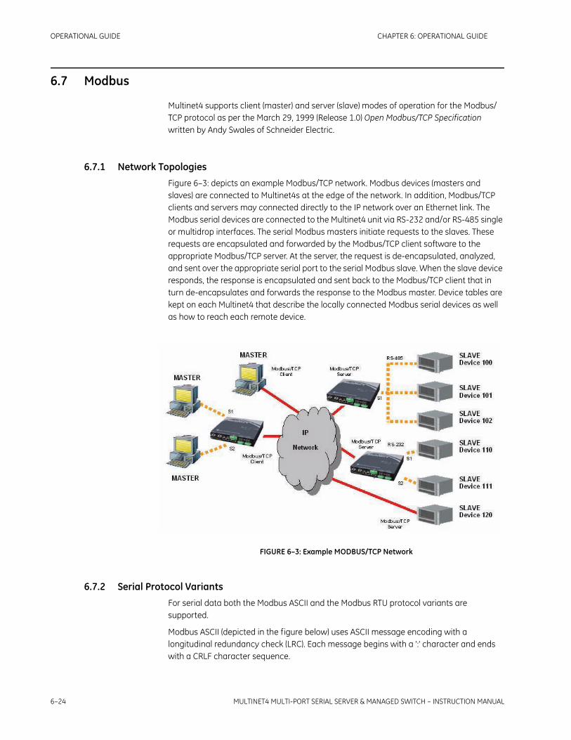
6–24 MULTINET4 MULTI-PORT SERIAL SERVER & MANAGED SWITCH – INSTRUCTION MANUAL
OPERATIONAL GUIDE CHAPTER 6: OPERATIONAL GUIDE
6.7 Modbus
Multinet4 supports client (master) and server (slave) modes of operation for the Modbus/TCP protocol as per the March 29, 1999 (Release 1.0) Open Modbus/TCP Specification written by Andy Swales of Schneider Electric.
6.7.1 Network TopologiesFigure 6–3: depicts an example Modbus/TCP network. Modbus devices (masters and slaves) are connected to Multinet4s at the edge of the network. In addition, Modbus/TCP clients and servers may connected directly to the IP network over an Ethernet link. The Modbus serial devices are connected to the Multinet4 unit via RS-232 and/or RS-485 single or multidrop interfaces. The serial Modbus masters initiate requests to the slaves. These requests are encapsulated and forwarded by the Modbus/TCP client software to the appropriate Modbus/TCP server. At the server, the request is de-encapsulated, analyzed, and sent over the appropriate serial port to the serial Modbus slave. When the slave device responds, the response is encapsulated and sent back to the Modbus/TCP client that in turn de-encapsulates and forwards the response to the Modbus master. Device tables are kept on each Multinet4 that describe the locally connected Modbus serial devices as well as how to reach each remote device.
FIGURE 6–3: Example MODBUS/TCP Network
6.7.2 Serial Protocol VariantsFor serial data both the Modbus ASCII and the Modbus RTU protocol variants are supported.
Modbus ASCII (depicted in the figure below) uses ASCII message encoding with a longitudinal redundancy check (LRC). Each message begins with a ':' character and ends with a CRLF character sequence.

CHAPTER 6: OPERATIONAL GUIDE OPERATIONAL GUIDE
MULTINET4 MULTI-PORT SERIAL SERVER & MANAGED SWITCH – INSTRUCTION MANUAL 6–25
FIGURE 6–4: Format of a Modbus ASCII Packet
Modbus RTU (depicted in the figure below) uses binary message encoding with a cyclic redundancy check (CRC). Each message begins with a silent interval of at least 3.5 characters times and ends with a similar silent interval.
FIGURE 6–5: Format of a Modbus RTU Packet
6.7.3 Network ProtocolThe Modbus/TCP format (depicted in the figure below) strips the message framing and LRC/CRC from the normal Modbus packet and prepends a Modbus/TCP header consisting of a 2-byte Transaction ID (set by the client and echoed by the server), a 2-byte Protocol ID (always 0-0), and a 2-byte length. The device address byte (now referred to as the unit identifier) and the function byte are preserved and are followed by a variable amount of data. This information is then delivered as the payload of a TCP/IP packet. The Modbus LRC/CRC is not included because it is redundant with the CRC provided by the link layer (that is, Ethernet).
FIGURE 6–6: Format of a Modbus/TCP Packet
6.7.4 Exception HandlingThe Modbus/TCP client and server on Multinet4 can optionally generate and forward Modbus exception codes when certain communication or configuration failures occur. Specifically, the client will generate a GATEWAY PATH UNAVAILABLE exception message (exception code 0x0A) and pass it back to the master device if a remote address has not been configured for the destination device. The server will generate a similar message if a local device entry has not been configured for the destination device address. The message is sent to the client, which then forwards the exception to the Modbus master device.

6–26 MULTINET4 MULTI-PORT SERIAL SERVER & MANAGED SWITCH – INSTRUCTION MANUAL
OPERATIONAL GUIDE CHAPTER 6: OPERATIONAL GUIDE
In addition the server will generate a GATEWAY TARGET DEVICE FAILED TO RESPOND exception message (exception code 0x0B) when the destination device does not respond to a request within a user-configured interval. This message is sent to the client, which then forwards the exception to the Modbus master device.
6.7.5 TCP Connection HandlingTCP connection handling performed by Multinet4 complies with the implementation guidelines spelled out in Appendix A of the Open Modbus/TCP Specification.
When the Modbus/TCP client software receives a request from an attached serial Modbus master it analyzes the packet and determines the destination device address. It checks to see if it already has an open TCP connection for the destination. If not, the client attempts to open a new TCP connection to the appropriate Modbus/TCP server. Once a connection is established the request message is sent and the client waits for a response. After the response is received it is forwarded back to the master.
After the transaction is complete the TCP connection remains open in anticipation of a subsequent request. If another request is not made within the user-configured idle time the TCP connection is closed and will be re-opened when a new request is received. The client may also be configured so that it immediately makes a connection for a configured device and keeps that connection open indefinitely. This mode eliminates the latency associated with making the TCP connection for the initial request.
If a response is not received the Modbus/TCP client will time out after a user-configured interval. After a timeout, the TCP connection is closed to eliminate the possibility of receiving an unexpected late response. In addition the GATEWAY TARGET DEVICE FAILED TO RESPOND (exception code 0x0B) exception message is sent to the Modbus Master, which can then make the decision on whether or not to retry. If the client is configured to hold connections open indefinitely a new connection will be established with the remote server immediately following the timeout; otherwise, the client waits for the next Modbus request before re-opening the connection.
The Modbus/TCP server process always listens for connections on TCP port 502.

CHAPTER 6: OPERATIONAL GUIDE OPERATIONAL GUIDE
MULTINET4 MULTI-PORT SERIAL SERVER & MANAGED SWITCH – INSTRUCTION MANUAL 6–27
6.8 User Account Management
Multinet4 supports three separate user groups with different privileges:
6.8.1 User Groups• Admin – An administrator can access all features.
• Read/Write – A read/write operator can access all features except the following web menu items (and any related CLI commands):
• Administration / SNMP / *
• Administration / Authentication / *
• Administration / Sessions / *
• Administration / Software Upgrade
• Administration / Configuration / *
• Administration / System Reboot
• Events / Logs / Global Settings
• Security / Keys
• Security / Certificates
• Security / RADIUS / *
• Read Only – read-only operator can access all features that a read/write operator can access but does not have the ability to apply or save configuration settings.

6–28 MULTINET4 MULTI-PORT SERIAL SERVER & MANAGED SWITCH – INSTRUCTION MANUAL
OPERATIONAL GUIDE CHAPTER 6: OPERATIONAL GUIDE

MULTINET4 MULTI-PORT SERIAL SERVER & MANAGED SWITCH – INSTRUCTION MANUAL 7–1
Multinet4 Multi-Port Serial Server & Managed Switch
Chapter 7: Terminal Server Application Notes
Digital EnergyMultilin
Terminal Server Application Notes
7.1 What is a Terminal Server?
A Terminal Server is a device or software application that can pass data between a standard serial protocol link and an IP-based network. The Terminal Server functionality of the Multinet4 Series provides a service that encapsulates asynchronous serial data in a TCP/IP stream. Service provisioning is flexible and allows a number of different configurations as described below.
7.1.1 Serial Protocol StandardsThere are many techniques for passing serial binary data between two or more digital systems. A number of popular methods based on standards published by the ITU-T are commonly referred to as "serial" protocols. Two of the most popular of these interfaces are EIA-232 (also know as RS-232) and EIA-485 (also known as RS-485).
Interfaces that support RS-232 (or some subset of the standard) are ubiquitous and found on nearly all personal computers. They also appear on many embedded computing devices where they are used to carry streaming data or provide access to a user console. An RS-232 link provides full-duplex data and asymmetric control. One device on the link is defined as the DTE (Data Terminal Equipment) and the other device is defined as the DCE (Data Communications Equipment). Traditionally, a DTE was a computer system and a DCE was a communications device such as a modem. Handshaking signals provide for flow control as well as valid link detection. Data rates typically range from 150bps to 115Kbps over distances up to 10 meters.
Interfaces that support RS-485 are less common; however, this protocol has a number of advantages over RS-232. RS-485 can be configured as a 4-wire, full duplex channel or a 2-wire, half duplex channel. It may also be operated in point-to-point or multi-point topologies (RS-232 only supports point-to-point). Because the standard uses differential

7–2 MULTINET4 MULTI-PORT SERIAL SERVER & MANAGED SWITCH – INSTRUCTION MANUAL
TERMINAL SERVER APPLICATION NOTES CHAPTER 7: TERMINAL SERVER APPLICATION NOTES
signaling over twisted pair, it can run over long distances, up to a kilometer. Maximum theoretical data transmission speeds are also higher than RS-232, up to 30Mbps over short distances.
7.1.2 Networking StandardsSerial data transfer standards like RS-232 and RS-485 are generally insufficient for implementing modern digital communication networks. In the past, these networks have been constructed using a number of available technologies but industrial applications are increasingly shifting toward running the Internet Protocol (IP) over Ethernet-based technologies. This enables the deployment of highly interoperable, reliable, and secure high-speed networks at extremely low cost. The IEEE is responsible for publishing standards related to Ethernet. A large body of such standards exists as IEEE 802.x. Data transfer rates range from 10Mbps to 1000Mbps depending on the physical layer technology employed. Distances can run up to 100 meters on twisted pair cables and for tens of kilometers using fiber optic transceivers.

CHAPTER 7: TERMINAL SERVER APPLICATION NOTES TERMINAL SERVER APPLICATION NOTES
MULTINET4 MULTI-PORT SERIAL SERVER & MANAGED SWITCH – INSTRUCTION MANUAL 7–3
7.2 Bridging the Gap between Serial and Network Communication
A Terminal Server is a device or software application that can pass data between a standard serial protocol link and an Ethernet-based network. The figure below illustrates passing characters from an RS-232 port over a TCP/IP connection.
FIGURE 7–1: Serial Over TCP/IP
Without a terminal server, the host system in the above figure must connect to the DCE device over a serial cable. Some of the advantages of using a terminal server are:
1. The distance between the computer system and the end device is increased significantly. The effective maximum range of an RS-232 link is about 10 meters. With a terminal server, the computer system connects to the device over a network and the effective maximum range is limited only by the latency requirements of the communicating end systems.
2. Multiple computer systems can communicate with a single RS-232 device. This would be impossible using just an RS-232 link because it only operates in point-to-point topologies. The terminal server performs a multiplexing function that passes data from multiple endpoints over the single RS-232 link.
3. Connections between relatively large numbers of communicating end systems are supported over a common cabling infrastructure. Without a terminal server, limitations imposed by the RS-232/485 standards would likely require many dedicated lines between end systems.

7–4 MULTINET4 MULTI-PORT SERIAL SERVER & MANAGED SWITCH – INSTRUCTION MANUAL
TERMINAL SERVER APPLICATION NOTES CHAPTER 7: TERMINAL SERVER APPLICATION NOTES
7.3 Terminal Server Operation
The Multinet4 offers a terminal server function that transports serial characters over a TCP/IP network. A flexible set of connection options allows the user to configure each serial port for a different mode of operation. The terminal server functionality is organized into serial communication channels that may be added or deleted from the system. Each channel is associated with a particular serial port and operates either in passive or active mode.
7.3.1 Passive Mode ChannelsWhen a terminal server channel operates in passive (server) mode, it waits for incoming TCP connection requests. When a request is received it is accepted if the following criteria are met:
• serial port operational state is UP
• maximum number of incoming connections will not be exceeded
After a connection request is accepted, the TCP connection becomes active and serial data may be transmitted and received on the channel.
A terminal server channel operates in passive mode if the “Call Direction” parameter is set to “IN."
The following configuration parameters also affect the operation of the port in passive mode:
• Local IP – the IP address at which the server listens for connections. If the system has only a single assigned IP address, this parameter defaults to the system IP address and cannot be changed. If the system has multiple assigned IP addresses, this parameter can be set to any of those addresses. In this case, the software will only accept connections destined for the configured IP address. The port will not be reachable using other IP addresses, even if they are assigned to the system.
• Local TCP – the TCP port at which the server listens for connections. The TCP port may be in the range 1000 to 65535. It is invalid to assign the same TCP port to multiple terminal server serial ports.
• Maximum Connections – the maximum number of incoming connections that will be accepted for the terminal server serial port. Up to 5 simultaneous incoming connections are supported per serial port.
7.3.2 Active Mode ChannelsWhen a terminal server port operates in active (client) mode, it actively attempts to connect to a specified remote host whenever the serial port operational state is UP.
After an outgoing connection request is accepted by the remote host, the TCP connection becomes active and serial data may be transmitted and received on the channel.
A terminal server port operates in active mode if the “Call Direction” parameter is set to “OUT".
CHAPTER 7: TERMINAL SERVER APPLICATION NOTES TERMINAL SERVER APPLICATION NOTES
MULTINET4 MULTI-PORT SERIAL SERVER & MANAGED SWITCH – INSTRUCTION MANUAL 7–5
The following configuration parameters also effect the operation of the port in active mode:
• Local IP – the IP address to which the channel binds before making an outgoing connection. This is the address used in a transmitted packet's source address IP header field.
• Local TCP– the TCP port to which the channel binds before making an outgoing connection. The TCP port may be in the range 1000 to 65535. This is the port number used in a transmitted packet's source port TCP header field. It is invalid to assign the same TCP port to multiple terminal server channels. When a channel is configured in active mode, it is also valid to assign a value of '0' for the Local TCP port. This tells the system that it can select any unused port number as the local TCP port for this connection.
• Remote IP – the IP address to which the terminal server attempts to connect
• Remote TCP – the TCP port to which the terminal server attempts to connect
• Retry Time – when a connection attempt fails (for any reason), this is the minimum amount of time the terminal server will wait before re-trying the attempt.
7.3.3 Mixed ModeYou can configure a terminal server port to operate in a mixed mode in which it simultaneously acts as both a passive server and an active client. This is accomplished by adding an "IN" channel as well as at least one "OUT" channel that uses the port. In general, this mode should be used with care. If you configure both sides of a connection with a mixed mode you can produce redundant TCP connections.
7.3.4 Session TypeEach terminal server port can be configured as a raw TCP connection or as a Telnet connection. Generally, the session type should be specified as raw (the default) unless you plan on connecting to the port using a telnet application. This may be appropriate in certain cases where you are accessing a device console port using the terminal server. Such a case is illustrated in section 7.3.4: Session Type.

7–6 MULTINET4 MULTI-PORT SERIAL SERVER & MANAGED SWITCH – INSTRUCTION MANUAL
TERMINAL SERVER APPLICATION NOTES CHAPTER 7: TERMINAL SERVER APPLICATION NOTES
7.4 Application #1: Device Console Access
The terminal server is used to remotely access the console on an RTU using telnet.
FIGURE 7–2: Device Console Access
The Multinet4 is configured as follows:
FIGURE 7–3: Configuration for Device Console Access

CHAPTER 7: TERMINAL SERVER APPLICATION NOTES TERMINAL SERVER APPLICATION NOTES
MULTINET4 MULTI-PORT SERIAL SERVER & MANAGED SWITCH – INSTRUCTION MANUAL 7–7
The user then executes a telnet client application on the host system to open a connection to 192.168.1.2 on port 10201:
If serial port S1 is UP and the terminal server is reachable by the host, a TCP connection will be established:
FIGURE 7–4: TCP Connection Confirmed

7–8 MULTINET4 MULTI-PORT SERIAL SERVER & MANAGED SWITCH – INSTRUCTION MANUAL
TERMINAL SERVER APPLICATION NOTES CHAPTER 7: TERMINAL SERVER APPLICATION NOTES
7.5 Application #2: Serial-over-TCP/IP Tunnel
Two Multinet4 Multi-Port Serial Server & Managed Switch devices are used to connect a user's host system to an RTU console over a TCP/IP network.
FIGURE 7–5: Serial-over-TCP/IP Tunnel
The Multinet4 is configured as illustrated in the figure below:
FIGURE 7–6: Multinet4 Configured for Serial-over-TCP/IP Tunnel

CHAPTER 7: TERMINAL SERVER APPLICATION NOTES TERMINAL SERVER APPLICATION NOTES
MULTINET4 MULTI-PORT SERIAL SERVER & MANAGED SWITCH – INSTRUCTION MANUAL 7–9
When serial port S1 is UP on each unit, a TCP connection is established between the two. Confirmation of the connection is illustrated in the figure below.
FIGURE 7–7: TCP Connection Established
After the connection is established, the computer system acting as a terminal can communicate with the RTU through its local serial port.
Note When creating a TCP/IP tunnel between two serial ports, you should always choose one node to be the client (the "OUT" channel) and the other to be the server (the "IN" channel). Configuring a client and a server for the port on each side will result in redundant TCP connections and each serial port will end up seeing "duplicate" characters.

7–10 MULTINET4 MULTI-PORT SERIAL SERVER & MANAGED SWITCH – INSTRUCTION MANUAL
TERMINAL SERVER APPLICATION NOTES CHAPTER 7: TERMINAL SERVER APPLICATION NOTES
7.6 Application #3: Multipoint SCADA
Three Multinet4 devices are used to connect three serial devices over a TCP/IP network. One of the serial devices is a SCADA master and the other two are slaves. The MN4-1 (connected to the master) is configured to make one active connection to MN4-2 and MN4-3 (each connected to one slave device).
FIGURE 7–8: Multipoint SCADA
The Multinet4 is configured as illustrated in the figure below:

CHAPTER 7: TERMINAL SERVER APPLICATION NOTES TERMINAL SERVER APPLICATION NOTES
MULTINET4 MULTI-PORT SERIAL SERVER & MANAGED SWITCH – INSTRUCTION MANUAL 7–11
FIGURE 7–9: Multinet4 Configured for Multipoint SCADA
The Multinet4 is configured as illustrated in the figure below:
FIGURE 7–10: MN4-2,3 Configured for Multipoint SCADA

7–12 MULTINET4 MULTI-PORT SERIAL SERVER & MANAGED SWITCH – INSTRUCTION MANUAL
TERMINAL SERVER APPLICATION NOTES CHAPTER 7: TERMINAL SERVER APPLICATION NOTES
7.7 Using Multinet4 Secure Serial Ports
For a detailed discussion of serial port security see section 6.5.2: Serial Port Security.

CHAPTER 7: TERMINAL SERVER APPLICATION NOTES TERMINAL SERVER APPLICATION NOTES
MULTINET4 MULTI-PORT SERIAL SERVER & MANAGED SWITCH – INSTRUCTION MANUAL 7–13
7.8 Application #4: Serial-over-Secure-TCP Tunnel
Two Multinet4 devices are used to connect two serial devices over a TCP/IP network. This example is like Application #2 except that all of the serial data passing over the network is encrypted. In addition, the initial connection includes an SSL handshake that forces each side to authenticate using RSA keys and X.509 certificates. This setup not only prevents intruders from snooping on active serial sessions but it also prevents them from connecting to an open terminal server port and impersonating a host.
FIGURE 7–11: Serial-over-Secure-TCP Tunnel
Both sides of the terminal server connection must be configured for SSL.
SSL is configured on the Multinet4 for serial port S1 as shown in the figure below:
FIGURE 7–12: Multinet4 Configured for Serial-over-SSL Tunnel

7–14 MULTINET4 MULTI-PORT SERIAL SERVER & MANAGED SWITCH – INSTRUCTION MANUAL
TERMINAL SERVER APPLICATION NOTES CHAPTER 7: TERMINAL SERVER APPLICATION NOTES
The basic terminal server parameters are configured as in Application #2. When serial port S1 is UP on each side the TCP connection is established, the SSL handshake is performed, and then encrypted serial data can be passed over the network as shown in the figure below:
FIGURE 7–13: Serial-over-SSL Tunnel Connection

CHAPTER 7: TERMINAL SERVER APPLICATION NOTES TERMINAL SERVER APPLICATION NOTES
MULTINET4 MULTI-PORT SERIAL SERVER & MANAGED SWITCH – INSTRUCTION MANUAL 7–15
7.9 Troubleshooting Terminal Server SSL Connections
If a terminal server connection between two Multinet4s cannot be established, use the table below to determine what is wrong.
Table 7–1: Troubleshooting Terminal Server Connections
Example Symptom Problem Resolution
Connection is not made and no events appear in the event log.
The local Multinet4 unit is not attempting to connect out.
Verify that the serial port is enabled and in the UP operational state. A connection will not be attempted from a serial port that is DOWN or DISABLED.Note: Enabling a serial port and setting “Ignore DSS” to TRUE will force a serial port into the UP state.
Event: "Serial port S1 reports that the host at 192.168.1.2 is unreachable"Event: "Serial port S1 reports that the host at 192.168.1.2 is down"Event: "Serial port S1 reports that the connection to the host at 192.168.1.2 (10201) was refused"
The local Multinet4 unit attempted to connect to the remote unit but it was unreachable or the TCP port is not open.
Verify that the remote unit is reachable by logging into the Command Line Interface (CLI) and using the ping command.Verify that the specified port is open/available on the remote unit by using a PC to telnet to the port. If the connection is refused, your remote unit is probably not configured properly.Verify that the operational state of the remote serial port is UP. A connection will not be accepted on a port that is in the DOWN or DISABLED state.
Event: "Serial port S1 experienced a problem (unsupported protocol) while connecting to the host at 192.168.1.2 (10201)"
The SSL handshake could not complete because the peer is attempting to use a protocol that we do not support.
Check your configuration. Make sure that both sides of the connection allow compatible cipher suites.
Event: "Serial port S1 experienced a problem (no shared cipher) while connecting to the host at 192.168.1.2 (10201)"
The SSL handshake could not complete because no shared cipher was available.
Check your configuration. Make sure that both sides of the connection allow compatible ciphers suites.

7–16 MULTINET4 MULTI-PORT SERIAL SERVER & MANAGED SWITCH – INSTRUCTION MANUAL
TERMINAL SERVER APPLICATION NOTES CHAPTER 7: TERMINAL SERVER APPLICATION NOTES
Event: "Serial port S1 reports that the certificate presented by the host at 192.168.1.2 (10201) was invalid (certificate has expired)"Event: "Serial port S1 reports that the certificate presented by the host at 192.168.1.2 (10201) was invalid (certificate is not yet valid)"
The SSL handshake failed during certificate verification because the current day and time are not within the peer certificate's valid date range
Make sure your system's time and date is set properly.Check the certificate on the other system and make it has appropriate "notBefore" and "notAfter" dates.
Event: "Serial port S1 received a notification (sslv3 alert certificate expired) from the host at 192.168.1.2 (10201)"
The SSL handshake failed during certificate verification because your certificate has expired.
Make sure the other system’s time and date are set properly.Check your key file and make sure that the enclosed certificate file has appropriate “notBefore” and “notAfter” dates.
Event: "Serial port S1 reports that the certificate presented by the host at 192.168.1.2 (10201) was invalid (self signed certificate in certificate chain)"
The SSL handshake failed during certificate verification because an un-trusted self-signed certificate was found in the chain.
Make sure that you have installed the peer’s root CA certificate and have marked it as trusted.
Event: “SSL: Message from peer on channel SX (tlsv1 alert unknown ca)."
The SSL handshake failed during certificate verification because you presented an un-trusted self-signed certificate in your certificate chain.
Make sure that you are presenting a valid certificate chain (that is, each certificate in a valid chain is signed by the next certificate in the chain, except for the final certificate, which is a self-signed root CA certificate).Make sure that the other system has installed your CA’s certificate and marked it as trusted.
Table 7–1: Troubleshooting Terminal Server Connections
Example Symptom Problem Resolution

MULTINET4 MULTI-PORT SERIAL SERVER & MANAGED SWITCH – INSTRUCTION MANUAL A–1
Multinet4 Multi-Port Serial Server & Managed Switch
Chapter A: Port and Type Reference
Digital EnergyMultilin
Port and Type Reference
A.1 Well Known TCP/UDP Network Ports
Transmission Control Protocol (TCP) and User Datagram Protocol (UDP) are members of the Internet Protocol Suite. They enable the transmission of data among networked computers by directing traffic to ports associated with specific functions.
TCP is a connection-oriented protocol; that is, it creates an identified connection from client to server for the transmission of data. TCP provides a very reliable interface to a specified port.
UDP is a simpler message-based connectionless protocol; that is, UDP simply sends a packet of data to a specified address and port. UDP does not provide the reliability of TCP but it can deliver data with less overhead.
Network port numbers are assigned to specific uses by the Internet Assigned Numbers Authority (IANA). Port numbers 0-1023 are called Well Known Ports and have standard uses, such as port 80 for HTML traffic. Port numbers 1024-49151 are reserved for Registered Ports, and port numbers 49152-65535 are the dynamic ports which can be put to any use.
Comprehensive lists of the conventional uses of all Well Known and Registered ports are available on the internet and in publications. The table below is a partial list of official Well Known ports.
Table A–1: Well Known Ports
Port Description
0/TCP,UDP Reserved
1/TCP,UDP TCPMUX (TCP port service multiplexer)
5/TCP,UDP RJE (Remote Job Entry)

A–2 MULTINET4 MULTI-PORT SERIAL SERVER & MANAGED SWITCH – INSTRUCTION MANUAL
PORT AND TYPE REFERENCE CHAPTER A: PORT AND TYPE REFERENCE
7/TCP,UDP ECHO protocol
9/TCP,UDP DISCARD protocol
13/TCP,UDP DAYTIME protocol
17/TCP,UDP QOTD (Quote of the Day) protocol
18/TCP,UDP Message Send Protocol
19/TCP,UDP CHARGEN (Character Generator) protocol
20/TCP,UDP FTP - data port
21/TCP,UDP FTP - control (command) port
22/TCP,UDP SSH (Secure Shell)
23/TCP,UDP Telnet protocol
25/TCP,UDP SMTP
37/TCP,UDP TIME protocol
38/TCP,UDP Route Access Protocol
39/TCP,UDP Resource Location Protocol
41/TCP,UDP Graphics
42/TCP,UDP Host Name Server
43/TCP WHOIS protocol
49/TCP,UDP TACACS Login Host protocol
53/TCP,UDP DNS (Domain Name System)
67/UDP BOOTP (BootStrap Protocol) server; also used by DHCP (Dynamic Host Configuration Protocol)
68/UDP BOOTP client; also used by DHCP
69/UDP TFTP (Trivial File Transfer Protocol)
70/TCP Gopher protocol
79/TCP Finger protocol
80/TCP HTTP (HyperText Transfer Protocol)
88/TCP Kerberos - authenticating agent
110/TCP POP3 (Post Office Protocol version 3)
113/TCP ident
118/TCP,UDP SQL Services
119/TCP NNTP (Network News Transfer Protocol)
Table A–1: Well Known Ports
Port Description

CHAPTER A: PORT AND TYPE REFERENCE PORT AND TYPE REFERENCE
MULTINET4 MULTI-PORT SERIAL SERVER & MANAGED SWITCH – INSTRUCTION MANUAL A–3
123/UDP NTP (Network Time Protocol)
135/TCP,UDP EPMAP / Microsoft RPC Locator Service
137/TCP,UDP NetBIOS Name Service
138/TCP,UDP NetBIOS Datagram Service
139/TCP,UDP NetBIOS Session Service
143/TCP,UDP IMAP4 (Internet Message Access Protocol 4)
156/TCP,UDP SQL Service
161/TCP,UDP SNMP (Simple Network Management Protocol)
162/TCP,UDP SNMPTRAP
179/TCP BGP (Border Gateway Protocol)
194/TCP IRC (Internet Relay Chat)
213/TCP,UDP IPX
369/TCP,UDP Rpc2portmap
371/TCP,UDP ClearCase albd
389/TCP,UDP LDAP (Lightweight Directory Access Protocol)
401/TCP,UDP UPS Uninterruptible Power Supply
427/TCP,UDP SLP (Service Location Protocol)
443/TCP,UDP HTTPS - HTTP Protocol over TLS/SSL (encrypted transmission)
445/TCP Microsoft-DS (Active Directory, Windows shares, Sasser worm, Agobot, Zobotworm)
445/UDP Microsoft-DS SMB file sharing
464/TCP,UDP Kerberos Change/Set password
500/TCP,UDP ISAKMP, IKE-Internet Key Exchange
514/UDP syslog protocol
520/UDP Routing - RIP
524/TCP,UDP NCP (NetWare Core Protocol)
530/TCP,UDP RPC
540/TCP UUCP (Unix-to-Unix Copy Protocol)
542/TCP,UDP commerce (Commerce Applications)
554/TCP,UDP RTSP (Real Time Streaming Protocol)
563/TCP,UDP NNTP protocol over TLS/SSL (NNTPS)
Table A–1: Well Known Ports
Port Description

A–4 MULTINET4 MULTI-PORT SERIAL SERVER & MANAGED SWITCH – INSTRUCTION MANUAL
PORT AND TYPE REFERENCE CHAPTER A: PORT AND TYPE REFERENCE
587/TCP email message submission (SMTP) (RFC 2476)
591/TCP FileMaker 6.0 Web Sharing (HTTP Alternate, see port 80)
593/TCP,UDP HTTP RPC Ep Map
636/TCP,UDP LDAP over SSL (encrypted transmission)
691/TCP MS Exchange Routing
873/TCP rsync File synchronization protocol
989/TCP,UDP FTP Protocol (data) over TLS/SSL
990/TCP,UDP FTP Protocol (control) over TLS/SSL
992/TCP,UDP Telnet protocol over TLS/SSL
993/TCP IMAP4 over SSL (encrypted transmission)
995/TCP POP3 over SSL (encrypted transmission)
Table A–1: Well Known Ports
Port Description

CHAPTER A: PORT AND TYPE REFERENCE PORT AND TYPE REFERENCE
MULTINET4 MULTI-PORT SERIAL SERVER & MANAGED SWITCH – INSTRUCTION MANUAL A–5
A.2 ICMP Types
The Internet Control Message Protocol (ICMP) is a core protocol of the Internet protocol suite. It is mainly used to send error messages. Unlike TCP and UDP, ICMP is usually not used by network applications (with the exception of the ping application).
The table below is a list of the ICMP types.
Table A–2: ICMP Types
Port Description
0 Echo Reply
1 Unassigned
2 Unassigned
3 Destination Unreachable
4 Source Quench
5 Redirect
6 Alternate Host Address
7 Unassigned
8 Echo
9 Router Advertisement
10 Router Selection
11 Time Exceeded
12 Parameter Problem
13 Timestamp
14 Timestamp Reply
15 Information Request
16 Information Reply
17 Address Mask Request
18 Address Mask Reply
19 Reserved (for Security)
20-29 Reserved (for Robustness Experiment)
30 Traceroute
31 Datagram Conversion Error
32 Mobile Host Redirect

A–6 MULTINET4 MULTI-PORT SERIAL SERVER & MANAGED SWITCH – INSTRUCTION MANUAL
PORT AND TYPE REFERENCE CHAPTER A: PORT AND TYPE REFERENCE
33 IPv6 Where-Are-You
34 IPv6 I-Am-Here
35 Mobile Registration Request
36 Mobile Registration Reply
37 Domain Name Request
38 Domain Name Reply
39 SKIP
40 Photuris
41-255 Reserved
Table A–2: ICMP Types
Port Description

MULTINET4 MULTI-PORT SERIAL SERVER & MANAGED SWITCH – INSTRUCTION MANUAL B–1
Multinet4 Multi-Port Serial Server & Managed Switch
Chapter B: Third Party Licenses
Digital EnergyMultilin
Third Party Licenses
This appendix contains the texts of required licenses for third party software.
B.1 GNU Lesser General Public License
Version 2.1, February 1999 Copyright (C) 1991, 1999 Free Software Foundation, Inc.51 Franklin Street, Fifth Floor, Boston, MA 02110-1301 USAEveryone is permitted to copy and distribute verbatim copiesof this license document, but changing it is not allowed.
B.1.1 PreambleThe licenses for most software are designed to take away your freedom to share and change it. By contrast, the GNU General Public Licenses are intended to guarantee your freedom to share and change free software--to make sure the software is free for all its users.
This license, the Lesser General Public License, applies to some specially designated software packages--typically libraries--of the Free Software Foundation and other authors who decide to use it . You can use it too, but we suggest you first think carefully about whether this license or the ordinary General Public License is the better strategy to use in any particular case, based on the explanations below.
When we speak of free software, we are referring to freedom of use, not price. Our General Public Licenses are designed to make sure that you have the freedom to distribute copies of free software (and charge for this service if you wish); that you receive source code or can get it if you want it; that you can change the software and use pieces of it in new free programs; and that you are informed that you can do these things.
To protect your rights, we need to make restrictions that forbid distributors to deny you these rights or to ask you to surrender these rights. These restrictions translate to certain responsibilities for you if you distribute copies of the library or if you modify it .

B–2 MULTINET4 MULTI-PORT SERIAL SERVER & MANAGED SWITCH – INSTRUCTION MANUAL
THIRD PARTY LICENSES CHAPTER B: THIRD PARTY LICENSES
For example, if you distribute copies of the library, whether gratis or for a fee, you must give the recipients all the rights that we gave you. You must make sure that they, too, receive or can get the source code. If you link other code with the library, you must provide complete object files to the recipients, so that they can relink them with the library after making changes to the library and recompiling it . And you must show them these terms so they know their rights.
We protect your rights with a two-step method: (1) we copyright the library, and (2) we offer you this license, which gives you legal permission to copy, distribute and/or modify the library.
To protect each distributor, we want to make it very clear that there is no warranty for the free library. Also, if the library is modified by someone else and passed on, the recipients should know that what they have is not the original version, so that the original author's reputation will not be affected by problems that might be introduced by others.
Finally, software patents pose a constant threat to the existence of any free program. We wish to make sure that a company cannot effectively restrict the users of a free program by obtaining a restrictive license from a patent holder. Therefore, we insist that any patent license obtained for a version of the library must be consistent with the full freedom of use specified in this license.
Most GNU software, including some libraries, is covered by the ordinary GNU General Public License. This license, the GNU Lesser General Public License, applies to certain designated libraries, and is quite different from the ordinary General Public License. We use this license for certain libraries in order to permit linking those libraries into non-free programs.
When a program is linked with a library, whether statically or using a shared library, the combination of the two is legally speaking a combined work, a derivative of the original library. The ordinary General Public License therefore permits such linking only if the entire combination fits its criteria of freedom. The Lesser General Public License permits more lax criteria for linking other code with the library.
We call this license the "Lesser" General Public License because it does Less to protect the user's freedom than the ordinary General Public License. It also provides other free software developers Less of an advantage over competing non-free programs. These disadvantages are the reason we use the ordinary General Public License for many libraries. However, the Lesser license provides advantages in certain special circumstances.
For example, on rare occasions, there may be a special need to encourage the widest possible use of a certain library, so that it becomes a de-facto standard. To achieve this, non-free programs must be allowed to use the library. A more frequent case is that a free library does the same job as widely used non-free libraries. In this case, there is little to gain by limiting the free library to free software only, so we use the Lesser General Public License.
In other cases, permission to use a particular library in non-free programs enables a greater number of people to use a large body of free software. For example, permission to use the GNU C Library in non-free programs enables many more people to use the whole GNU operating system, as well as its variant, the GNU/Linux operating system.

CHAPTER B: THIRD PARTY LICENSES THIRD PARTY LICENSES
MULTINET4 MULTI-PORT SERIAL SERVER & MANAGED SWITCH – INSTRUCTION MANUAL B–3
Although the Lesser General Public License is Less protective of the users' freedom, it does ensure that the user of a program that is linked with the Library has the freedom and the wherewithal to run that program using a modified version of the Library.
The precise terms and conditions for copying, distribution and modification follow. Pay close attention to the difference between a "work based on the library" and a "work that uses the library". The former contains code derived from the library, whereas the latter must be combined with the library in order to run.

B–4 MULTINET4 MULTI-PORT SERIAL SERVER & MANAGED SWITCH – INSTRUCTION MANUAL
THIRD PARTY LICENSES CHAPTER B: THIRD PARTY LICENSES
B.2 TERMS AND CONDITIONS FOR COPYING, DISTRIBUTION AND MODIFICATION
1. This License Agreement applies to any software library or other program which contains a notice placed by the copyright holder or other authorized party saying it may be distributed under the terms of this Lesser General Public License (also called "this License"). Each licensee is addressed as "you".
A "library" means a collection of software functions and/or data prepared so as to be conveniently linked with application programs (which use some of those functions and data) to form executables.
The "Library", below, refers to any such software library or work which has been distributed under these terms. A "work based on the Library" means either the Library or any derivative work under copyright law: that is to say, a work containing the Library or a portion of it , either verbatim or with modifications and/or translated straightforwardly into another language. (Hereinafter, translation is included without limitation in the term "modification".)
"Source code" for a work means the preferred form of the work for making modifications to it . For a library, complete source code means all the source code for all modules it contains, plus any associated interface definition files, plus the scripts used to control compilation and installation of the library.
Activities other than copying, distribution and modification are not covered by this License; they are outside its scope. The act of running a program using the Library is not restricted, and output from such a program is covered only if its contents constitute a work based on the Library (independent of the use of the Library in a tool for writing it). Whether that is true depends on what the Library does and what the program that uses the Library does.
2. You may copy and distribute verbatim copies of the Library's complete source code as you receive it , in any medium, provided that you conspicuously and appropriately publish on each copy an appropriate copyright notice and disclaimer of warranty; keep intact all the notices that refer to this License and to the absence of any warranty; and distribute a copy of this License along with the Library.
You may charge a fee for the physical act of transferring a copy, and you may at your option offer warranty protection in exchange for a fee.
3. You may modify your copy or copies of the Library or any portion of it , thus forming a work based on the Library, and copy and distribute such modifications or work under the terms of Section 1 above, provided that you also meet all of these conditions:
1. The modified work must itself be a software library.
2. You must cause the files modified to carry prominent notices stating that you changed the files and the date of any change.
3. You must cause the whole of the work to be licensed at no charge to all third parties under the terms of this License.
4. If a facility in the modified Library refers to a function or a table of data to be supplied by an application program that uses the facility, other than as an argument passed when the facility is invoked, then you must make a good

CHAPTER B: THIRD PARTY LICENSES THIRD PARTY LICENSES
MULTINET4 MULTI-PORT SERIAL SERVER & MANAGED SWITCH – INSTRUCTION MANUAL B–5
faith effort to ensure that, in the event an application does not supply such function or table, the facility still operates, and performs whatever part of its purpose remains meaningful.
(For example, a function in a library to compute square roots has a purpose that is entirely well-defined independent of the application. Therefore, Subsection 2d requires that any application-supplied function or table used by this function must be optional: if the application does not supply it , the square root function must still compute square roots.)
These requirements apply to the modified work as a whole. If identifiable sections of that work are not derived from the Library, and can be reasonably considered independent and separate works in themselves, then this License, and its terms, do not apply to those sections when you distribute them as separate works. But when you distribute the same sections as part of a whole which is a work based on the Library, the distribution of the whole must be on the terms of this License, whose permissions for other licensees extend to the entire whole, and thus to each and every part regardless of who wrote it .
Thus, it is not the intent of this section to claim rights or contest your rights to work written entirely by you; rather, the intent is to exercise the right to control the distribution of derivative or collective works based on the Library.
In addition, mere aggregation of another work not based on the Library with the Library (or with a work based on the Library) on a volume of a storage or distribution medium does not bring the other work under the scope of this License.
5. You may opt to apply the terms of the ordinary GNU General Public License instead of this License to a given copy of the Library. To do this, you must alter all the notices that refer to this License, so that they refer to the ordinary GNU General Public License, version 2, instead of to this License. (If a newer version than version 2 of the ordinary GNU General Public License has appeared, then you can specify that version instead if you wish.) Do not make any other change in these notices.
Once this change is made in a given copy, it is irreversible for that copy, so the ordinary GNU General Public License applies to all subsequent copies and derivative works made from that copy.
This option is useful when you wish to copy part of the code of the Library into a program that is not a library.
6. You may copy and distribute the Library (or a portion or derivative of it , under Section 2) in object code or executable form under the terms of Sections 1 and 2 above provided that you accompany it with the complete corresponding machine-readable source code, which must be distributed under the terms of Sections 1 and 2 above on a medium customarily used for software interchange.
If distribution of object code is made by offering access to copy from a designated place, then offering equivalent access to copy the source code from the same place satisfies the requirement to distribute the source code, even though third parties are not compelled to copy the source along with the object code.
7. A program that contains no derivative of any portion of the Library, but is designed to work with the Library by being compiled or linked with it , is called a "work that uses the Library". Such a work, in isolation, is not a derivative work of the Library, and therefore falls outside the scope of this License.

B–6 MULTINET4 MULTI-PORT SERIAL SERVER & MANAGED SWITCH – INSTRUCTION MANUAL
THIRD PARTY LICENSES CHAPTER B: THIRD PARTY LICENSES
However, linking a "work that uses the Library" with the Library creates an executable that is a derivative of the Library (because it contains portions of the Library), rather than a "work that uses the library". The executable is therefore covered by this License. Section 6 states terms for distribution of such executables.
When a "work that uses the Library" uses material from a header file that is part of the Library, the object code for the work may be a derivative work of the Library even though the source code is not. Whether this is true is especially significant if the work can be linked without the Library, or if the work is itself a library. The threshold for this to be true is not precisely defined by law.
If such an object file uses only numerical parameters, data structure layouts and accessors, and small macros and small inline functions (ten lines or less in length), then the use of the object file is unrestricted, regardless of whether it is legally a derivative work. (Executables containing this object code plus portions of the Library will still fall under Section 6.)
Otherwise, if the work is a derivative of the Library, you may distribute the object code for the work under the terms of Section 6. Any executables containing that work also fall under Section 6, whether or not they are linked directly with the Library itself.
8. As an exception to the Sections above, you may also combine or link a "work that uses the Library" with the Library to produce a work containing portions of the Library, and distribute that work under terms of your choice, provided that the terms permit modification of the work for the customer's own use and reverse engineering for debugging such modifications.
You must give prominent notice with each copy of the work that the Library is used in it and that the Library and its use are covered by this License. You must supply a copy of this License. If the work during execution displays copyright notices, you must include the copyright notice for the Library among them, as well as a reference directing the user to the copy of this License. Also, you must do one of these things:
1. Accompany the work with the complete corresponding machine-readable source code for the Library including whatever changes were used in the work (which must be distributed under Sections 1 and 2 above); and, if the work is an executable linked with the Library, with the complete machine-readable "work that uses the Library", as object code and/or source code, so that the user can modify the Library and then relink to produce a modified executable containing the modified Library. (It is understood that the user who changes the contents of definitions files in the Library will not necessarily be able to recompile the application to use the modified definitions.)
2. Use a suitable shared library mechanism for linking with the Library. A suitable mechanism is one that (1) uses at run time a copy of the library already present on the user's computer system, rather than copying library functions into the executable, and (2) will operate properly with a modified version of the library, if the user installs one, as long as the modified version is interface-compatible with the version that the work was made with.
3. Accompany the work with a written offer, valid for at least three years, to give the same user the materials specified in Subsection 6a, above, for a charge no more than the cost of performing this distribution.

CHAPTER B: THIRD PARTY LICENSES THIRD PARTY LICENSES
MULTINET4 MULTI-PORT SERIAL SERVER & MANAGED SWITCH – INSTRUCTION MANUAL B–7
4. If distribution of the work is made by offering access to copy from a designated place, offer equivalent access to copy the above specified materials from the same place.
5. Verify that the user has already received a copy of these materials or that you have already sent this user a copy.
For an executable, the required form of the "work that uses the Library" must include any data and utility programs needed for reproducing the executable from it. However, as a special exception, the materials to be distributed need not include anything that is normally distributed (in either source or binary form) with the major components (compiler, kernel, and so on) of the operating system on which the executable runs, unless that component itself accompanies the executable.
It may happen that this requirement contradicts the license restrictions of other proprietary libraries that do not normally accompany the operating system. Such a contradiction means you cannot use both them and the Library together in an executable that you distribute.
6. You may place library facilities that are a work based on the Library side-by-side in a single library together with other library facilities not covered by this License, and distribute such a combined library, provided that the separate distribution of the work based on the Library and of the other library facilities is otherwise permitted, and provided that you do these two things:
1. Accompany the combined library with a copy of the same work based on the Library, uncombined with any other library facilities. This must be distributed under the terms of the Sections above.
2. Give prominent notice with the combined library of the fact that part of it is a work based on the Library, and explaining where to find the accompanying uncombined form of the same work.
3. You may not copy, modify, sublicense, link with, or distribute the Library except as expressly provided under this License. Any attempt otherwise to copy, modify, sublicense, link with, or distribute the Library is void, and will automatically terminate your rights under this License. However, parties who have received copies, or rights, from you under this License will not have their licenses terminated so long as such parties remain in full compliance.
4. You are not required to accept this License, since you have not signed it. However, nothing else grants you permission to modify or distribute the Library or its derivative works. These actions are prohibited by law if you do not accept this License. Therefore, by modifying or distributing the Library (or any work based on the Library), you indicate your acceptance of this License to do so, and all its terms and conditions for copying, distributing or modifying the Library or works based on it .
5. Each time you redistribute the Library (or any work based on the Library), the recipient automatically receives a license from the original licensor to copy, distribute, link with or modify the Library subject to these terms and conditions. You may not impose any further restrictions on the recipients' exercise of the rights granted herein. You are not responsible for enforcing compliance by third parties with this License.
6. If, as a consequence of a court judgment or allegation of patent infringement or for any other reason (not limited to patent issues), conditions are imposed on you (whether by court order, agreement or otherwise) that contradict the conditions of this

B–8 MULTINET4 MULTI-PORT SERIAL SERVER & MANAGED SWITCH – INSTRUCTION MANUAL
THIRD PARTY LICENSES CHAPTER B: THIRD PARTY LICENSES
License, they do not excuse you from the conditions of this License. If you cannot distribute so as to satisfy simultaneously your obligations under this License and any other pertinent obligations, then as a consequence you may not distribute the Library at all. For example, if a patent license would not permit royalty-free redistribution of the Library by all those who receive copies directly or indirectly through you, then the only way you could satisfy both it and this License would be to refrain entirely from distribution of the Library.
If any portion of this section is held invalid or unenforceable under any particular circumstance, the balance of the section is intended to apply, and the section as a whole is intended to apply in other circumstances.
It is not the purpose of this section to induce you to infringe any patents or other property right claims or to contest validity of any such claims; this section has the sole purpose of protecting the integrity of the free software distribution system which is implemented by public license practices. Many people have made generous contributions to the wide range of software distributed through that system in reliance on consistent application of that system; it is up to the author/donor to decide if he or she is willing to distribute software through any other system and a licensee cannot impose that choice.
This section is intended to make thoroughly clear what is believed to be a consequence of the rest of this License.
7. If the distribution and/or use of the Library is restricted in certain countries either by patents or by copyrighted interfaces, the original copyright holder who places the Library under this License may add an explicit geographical distribution limitation excluding those countries, so that distribution is permitted only in or among countries not thus excluded. In such case, this License incorporates the limitation as if written in the body of this License.
8. The Free Software Foundation may publish revised and/or new versions of the Lesser General Public License from time to time. Such new versions will be similar in spirit to the present version, but may differ in detail to address new problems or concerns.
Each version is given a distinguishing version number. If the Library specifies a version number of this License which applies to it and "any later version", you have the option of following the terms and conditions either of that version or of any later version published by the Free Software Foundation. If the Library does not specify a license version number, you may choose any version ever published by the Free Software Foundation.
9. If you wish to incorporate parts of the Library into other free programs whose distribution conditions are incompatible with these, write to the author to ask for permission. For software which is copyrighted by the Free Software Foundation, write to the Free Software Foundation; we sometimes make exceptions for this. Our decision will be guided by the two goals of preserving the free status of all derivatives of our free software and of promoting the sharing and reuse of software generally.
B.2.1 NO WARRANTY 10. BECAUSE THE LIBRARY IS LICENSED FREE OF CHARGE, THERE IS NO WARRANTY FOR
THE LIBRARY, TO THE EXTENT PERMITTED BY APPLICABLE LAW. EXCEPT WHEN OTHERWISE STATED IN WRITING THE COPYRIGHT HOLDERS AND/OR OTHER PARTIES

CHAPTER B: THIRD PARTY LICENSES THIRD PARTY LICENSES
MULTINET4 MULTI-PORT SERIAL SERVER & MANAGED SWITCH – INSTRUCTION MANUAL B–9
PROVIDE THE LIBRARY "AS IS" WITHOUT WARRANTY OF ANY KIND, EITHER EXPRESSED OR IMPLIED, INCLUDING, BUT NOT LIMITED TO, THE IMPLIED WARRANTIES OF MERCHANTABILITY AND FITNESS FOR A PARTICULAR PURPOSE. THE ENTIRE RISK AS TO THE QUALITY AND PERFORMANCE OF THE LIBRARY IS WITH YOU. SHOULD THE LIBRARY PROVE DEFECTIVE, YOU ASSUME THE COST OF ALL NECESSARY SERVICING, REPAIR OR CORRECTION.
11. IN NO EVENT UNLESS REQUIRED BY APPLICABLE LAW OR AGREED TO IN WRITING WILL ANY COPYRIGHT HOLDER, OR ANY OTHER PARTY WHO MAY MODIFY AND/OR REDISTRIBUTE THE LIBRARY AS PERMITTED ABOVE, BE LIABLE TO YOU FOR DAMAGES, INCLUDING ANY GENERAL, SPECIAL, INCIDENTAL OR CONSEQUENTIAL DAMAGES ARISING OUT OF THE USE OR INABILITY TO USE THE LIBRARY (INCLUDING BUT NOT LIMITED TO LOSS OF DATA OR DATA BEING RENDERED INACCURATE OR LOSSES SUSTAINED BY YOU OR THIRD PARTIES OR A FAILURE OF THE LIBRARY TO OPERATE WITH ANY OTHER SOFTWARE), EVEN IF SUCH HOLDER OR OTHER PARTY HAS BEEN ADVISED OF THE POSSIBILITY OF SUCH DAMAGES.
B.2.2 END OF TERMS AND CONDITIONS
B.2.2.1 How to Apply These Terms to Your New Libraries
If you develop a new library, and you want it to be of the greatest possible use to the public, we recommend making it free software that everyone can redistribute and change. You can do so by permitting redistribution under these terms (or, alternatively, under the terms of the ordinary General Public License).
To apply these terms, attach the following notices to the library. It is safest to attach them to the start of each source file to most effectively convey the exclusion of warranty; and each file should have at least the "copyright" line and a pointer to where the full notice is found.
• Use one line to give the library's name and an idea of what it does.
• Copyright (C) year name of author
This library is free software; you can redistribute it and/or modify it under the terms of the GNU Lesser General Public License as published by the Free Software Foundation; either version 2.1 of the License, or (at your option) any later version.
This library is distributed in the hope that it will be useful, but WITHOUT ANY WARRANTY; without even the implied warranty of MERCHANTABILITY or FITNESS FOR A PARTICULAR PURPOSE. See the GNU Lesser General Public License for more details.
You should have received a copy of the GNU Lesser General PublicLicense along with this library; if not, write to the Free Software
Foundation, Inc., 51 Franklin Street, Fifth Floor, Boston, MA 02110-1301 USA

B–10 MULTINET4 MULTI-PORT SERIAL SERVER & MANAGED SWITCH – INSTRUCTION MANUAL
THIRD PARTY LICENSES CHAPTER B: THIRD PARTY LICENSES

MULTINET4 MULTI-PORT SERIAL SERVER & MANAGED SWITCH – INSTRUCTION MANUAL C–1
Multinet4 Multi-Port Serial Server & Managed Switch
Chapter C: Modbus Memory Map
Digital EnergyMultilin
Modbus Memory Map
Address Qty Description Min Max Step Unit Format Default
0000 12 System Name - - - - String Varies
000C 12 System Contact - - - - String [email protected]
0018 12 System Location - - - - String Markham, Ontario
0024 6 Software Version - - - - String Varies
002A 1 IP Address[0] 0 255 1 - F1 0
002B 1 IP Address[1] 0 255 1 - F1 0
002C 1 IP Address[2] 0 255 1 - F1 0
002D 1 IP Address[3] 0 255 1 - F1 0
002E 1 NetMask[0] 0 255 1 - F1 0
002F 1 NetMask[1] 0 255 1 - F1 0
0030 1 NetMask[2] 0 255 1 - F1 0
0031 1 NetMask[3] 0 255 1 - F1 0
0032 1 GateWay[0] 0 255 1 - F1 0
0033 1 GateWay[1] 0 255 1 - F1 0
0034 1 GateWay[2] 0 255 1 - F1 0
0035 1 GateWay[3] 0 255 1 - F1 0
0036 3 MacAddress - - - - String Varies
0039 16 OrderCode - - - - String Varies
0049 1 PowerAlarm1 0 1 1 - F1 0
004A 1 PowerAlarm2 0 1 1 - F1 0

C–2 MULTINET4 MULTI-PORT SERIAL SERVER & MANAGED SWITCH – INSTRUCTION MANUAL
MODBUS MEMORY MAP CHAPTER C: MODBUS MEMORY MAP
004B 1 StpState 0 1 1 - F1 0
004C 2 Number of Ports 1 32 1 - F1 Varies
004E 2 Port Present Map - - - - Bitmap Varies
0050 2 Port Link Map - - - - Bitmap 0
0052 2 Port Stp State Map - - - - Bitmap 0
0054 2 Port Activity Map - - - - Bitmap 0
0056 1 Port 1 Type 0 6 1 - F1 Varies
0057 1 Port 2 Type 0 6 1 - F1 Varies
0058 1 Port 3 Type 0 6 1 - F1 Varies
0059 1 Port 4 Type 0 6 1 - F1 Varies
005A 1 Port 5 Type 0 6 1 - F1 Varies
005B 1 Port 6 Type 0 6 1 - F1 Varies
005C 1 Port 7 Type 0 6 1 - F1 Varies
005D 1 Port 8 Type 0 6 1 - F1 Varies
005E 1 Port 9 Type 0 6 1 - F1 Varies
005F 1 Port 10 Type 0 6 1 - F1 Varies
0060 1 Port 11 Type 0 6 1 - F1 Varies
0061 1 Port 12 Type 0 6 1 - F1 Varies
0062 1 Port 13 Type 0 6 1 - F1 Varies
0063 1 Port 14 Type 0 6 1 - F1 Varies
0064 1 Port 15 Type 0 6 1 - F1 Varies
0065 1 Port 16 Type 0 6 1 - F1 Varies
0066 1 Port 17 Type 0 6 1 - F1 Varies
0067 1 Port 18 Type 0 6 1 - F1 Varies
0068 1 Port 19 Type 0 6 1 - F1 Varies
0069 1 Port 20 Type 0 6 1 - F1 Varies
006A 1 Port 21 Type 0 6 1 - F1 Varies
006B 1 Port 22 Type 0 6 1 - F1 Varies
006C 1 Port 23 Type 0 6 1 - F1 Varies
006D 1 Port 24 Type 0 6 1 - F1 Varies
006E 1 Port 25 Type 0 6 1 - F1 Varies
006F 1 Port 26 Type 0 6 1 - F1 Varies
0070 1 Port 27 Type 0 6 1 - F1 Varies
0071 1 Port 28 Type 0 6 1 - F1 Varies
Address Qty Description Min Max Step Unit Format Default

CHAPTER C: MODBUS MEMORY MAP MODBUS MEMORY MAP
MULTINET4 MULTI-PORT SERIAL SERVER & MANAGED SWITCH – INSTRUCTION MANUAL C–3
0072 1 Port 29 Type 0 6 1 - F1 Varies
0073 1 Port 30 Type 0 6 1 - F1 Varies
0074 1 Port 31 Type 0 6 1 - F1 Varies
0075 1 Port 32 Type 0 6 1 - F1 Varies
0076 1 Port 1 Link Status 0 1 1 - F1 0
0077 1 Port 2 Link Status 0 1 1 - F1 0
0078 1 Port 3 Link Status 0 1 1 - F1 0
0079 1 Port 4 Link Status 0 1 1 - F1 0
007A 1 Port 5 Link Status 0 1 1 - F1 0
007B 1 Port 6 Link Status 0 1 1 - F1 0
007C 1 Port 7 Link Status 0 1 1 - F1 0
007D 1 Port 8 Link Status 0 1 1 - F1 0
007E 1 Port 9 Link Status 0 1 1 - F1 0
007F 1 Port 10 Link Status 0 1 1 - F1 0
0080 1 Port 11 Link Status 0 1 1 - F1 0
0081 1 Port 12 Link Status 0 1 1 - F1 0
0082 1 Port 13 Link Status 0 1 1 - F1 0
0083 1 Port 14 Link Status 0 1 1 - F1 0
0084 1 Port 15 Link Status 0 1 1 - F1 0
0085 1 Port 16 Link Status 0 1 1 - F1 0
0086 1 Port 17 Link Status 0 1 1 - F1 0
0087 1 Port 18 Link Status 0 1 1 - F1 0
0088 1 Port 19 Link Status 0 1 1 - F1 0
0089 1 Port 20 Link Status 0 1 1 - F1 0
008A 1 Port 21 Link Status 0 1 1 - F1 0
008B 1 Port 22 Link Status 0 1 1 - F1 0
008C 1 Port 23 Link Status 0 1 1 - F1 0
008D 1 Port 24 Link Status 0 1 1 - F1 0
008E 1 Port 25 Link Status 0 1 1 - F1 0
008F 1 Port 26 Link Status 0 1 1 - F1 0
0090 1 Port 27 Link Status 0 1 1 - F1 0
0091 1 Port 28 Link Status 0 1 1 - F1 0
0092 1 Port 29 Link Status 0 1 1 - F1 0
0093 1 Port 30 Link Status 0 1 1 - F1 0
Address Qty Description Min Max Step Unit Format Default

C–4 MULTINET4 MULTI-PORT SERIAL SERVER & MANAGED SWITCH – INSTRUCTION MANUAL
MODBUS MEMORY MAP CHAPTER C: MODBUS MEMORY MAP
0094 1 Port 31 Link Status 0 1 1 - F1 0
0095 1 Port 32 Link Status 0 1 1 - F1 0
0096 1 Port 1 STP State 0 1 1 - F1 0
0097 1 Port 2 STP State 0 1 1 - F1 0
0098 1 Port 3 STP State 0 1 1 - F1 0
0099 1 Port 4 STP State 0 1 1 - F1 0
009A 1 Port 5 STP State 0 1 1 - F1 0
009B 1 Port 6 STP State 0 1 1 - F1 0
009C 1 Port 7 STP State 0 1 1 - F1 0
009D 1 Port 8 STP State 0 1 1 - F1 0
009E 1 Port 9 STP State 0 1 1 - F1 0
009F 1 Port 10 STP State 0 1 1 - F1 0
00A0 1 Port 11 STP State 0 1 1 - F1 0
00A1 1 Port 12 STP State 0 1 1 - F1 0
00A2 1 Port 13 STP State 0 1 1 - F1 0
00A3 1 Port 14 STP State 0 1 1 - F1 0
00A4 1 Port 15 STP State 0 1 1 - F1 0
00A5 1 Port 16 STP State 0 1 1 - F1 0
00A6 1 Port 17 STP State 0 1 1 - F1 0
00A7 1 Port 18 STP State 0 1 1 - F1 0
00A8 1 Port 19 STP State 0 1 1 - F1 0
00A9 1 Port 20 STP State 0 1 1 - F1 0
00AA 1 Port 21 STP State 0 1 1 - F1 0
00AB 1 Port 22 STP State 0 1 1 - F1 0
00AC 1 Port 23 STP State 0 1 1 - F1 0
00AD 1 Port 24 STP State 0 1 1 - F1 0
00AE 1 Port 25 STP State 0 1 1 - F1 0
00AF 1 Port 26 STP State 0 1 1 - F1 0
00B0 1 Port 27 STP State 0 1 1 - F1 0
00B1 1 Port 28 STP State 0 1 1 - F1 0
00B2 1 Port 29 STP State 0 1 1 - F1 0
00B3 1 Port 30 STP State 0 1 1 - F1 0
00B4 1 Port 31 STP State 0 1 1 - F1 0
00B5 1 Port 32 STP State 0 1 1 - F1 0
Address Qty Description Min Max Step Unit Format Default

CHAPTER C: MODBUS MEMORY MAP MODBUS MEMORY MAP
MULTINET4 MULTI-PORT SERIAL SERVER & MANAGED SWITCH – INSTRUCTION MANUAL C–5
00B6 1 Port 1 Activity 0 1 1 - F1 0
00B7 1 Port 2 Activity 0 1 1 - F1 0
00B8 1 Port 3 Activity 0 1 1 - F1 0
00B9 1 Port 4 Activity 0 1 1 - F1 0
00BA 1 Port 5 Activity 0 1 1 - F1 0
00BB 1 Port 6 Activity 0 1 1 - F1 0
00BC 1 Port 7 Activity 0 1 1 - F1 0
00BD 1 Port 8 Activity 0 1 1 - F1 0
00BE 1 Port 9 Activity 0 1 1 - F1 0
00BF 1 Port 10 Activity 0 1 1 - F1 0
00C0 1 Port 11 Activity 0 1 1 - F1 0
00C1 1 Port 12 Activity 0 1 1 - F1 0
00C2 1 Port 13 Activity 0 1 1 - F1 0
00C3 1 Port 14 Activity 0 1 1 - F1 0
00C4 1 Port 15 Activity 0 1 1 - F1 0
00C5 1 Port 16 Activity 0 1 1 - F1 0
00C6 1 Port 17 Activity 0 1 1 - F1 0
00C7 1 Port 18 Activity 0 1 1 - F1 0
00C8 1 Port 19 Activity 0 1 1 - F1 0
00C9 1 Port 20 Activity 0 1 1 - F1 0
00CA 1 Port 21 Activity 0 1 1 - F1 0
00CB 1 Port 22 Activity 0 1 1 - F1 0
00CC 1 Port 23 Activity 0 1 1 - F1 0
00CD 1 Port 24 Activity 0 1 1 - F1 0
00CE 1 Port 25 Activity 0 1 1 - F1 0
00CF 1 Port 26 Activity 0 1 1 - F1 0
00D0 1 Port 27 Activity 0 1 1 - F1 0
00D1 1 Port 28 Activity 0 1 1 - F1 0
00D2 1 Port 29 Activity 0 1 1 - F1 0
00D3 1 Port 30 Activity 0 1 1 - F1 0
00D4 1 Port 31 Activity 0 1 1 - F1 0
00D5 1 Port 32 Activity 0 1 1 - F1 0
00D6 2 Port1 - Number of bytes received 0 4294967295
1 - F9 0
Address Qty Description Min Max Step Unit Format Default

C–6 MULTINET4 MULTI-PORT SERIAL SERVER & MANAGED SWITCH – INSTRUCTION MANUAL
MODBUS MEMORY MAP CHAPTER C: MODBUS MEMORY MAP
00D8 2 Port1 - Number of bytes sent 0 4294967295
1 - F9 0
00DA 2 Port1 - Number of frames received 0 4294967295
1 - F9 0
00DC 2 Port1 - Number of frames sent 0 4294967295
1 - F9 0
00DE 2 Port1 - Total bytes received 0 4294967295
1 - F9 0
00E0 2 Port1 - Total frames received 0 4294967295
1 - F9 0
00E2 2 Port1 - Number of broadcast frames received 0 4294967295
1 - F9 0
00E4 2 Port1 - Number of multicast frames received 0 4294967295
1 - F9 0
00E6 2 Port1 - Number of frames with CRC error 0 4294967295
1 - F9 0
00E8 2 Port1 - Number of oversized frames received 0 4294967295
1 - F9 0
00EA 2 Port1 - Number of bad fragments rcvd(<64 bytes)
0 4294967295
1 - F9 0
00EC 2 Port1 - Number of jabber frames received 0 4294967295
1 - F9 0
00EE 2 Port1 - Number of collisions occured 0 4294967295
1 - F9 0
00F0 2 Port1 - Number of late collisions occured 0 4294967295
1 - F9 0
00F2 2 Port1 - Number of 64-byte frames rcvd/sent 0 4294967295
1 - F9 0
00F4 2 Port1 - Number of 65-127 byte frames rcvd/sent 0 4294967295
1 - F9 0
00F6 2 Port1 - Number of 128-255 byte frames rcvd/sent
0 4294967295
1 - F9 0
00F8 2 Port1 - Number of 256-511 byte frames rcvd/sent
0 4294967295
1 - F9 0
00FA 2 Port1 - Number of 512-1023 byte frames rcvd/sent
0 4294967295
1 - F9 0
00FC 2 Port1 - Number of 1023-MAX byte frames rcvd/sent
0 4294967295
1 - F9 0
00FE 2 Port1 - Number of Mac Error Packets 0 4294967295
1 - F9 0
0100 2 Port1 - Number of dropped received packets 0 4294967295
1 - F9 0
0102 2 Port1 - Number of multicast frames sent 0 4294967295
1 - F9 0
0104 2 Port1 - Number of broadcast frames sent 0 4294967295
1 - F9 0
0106 2 Port1 - Number of <64 byte fragments w/ good CRC
0 4294967295
1 - F9 0
Address Qty Description Min Max Step Unit Format Default

CHAPTER C: MODBUS MEMORY MAP MODBUS MEMORY MAP
MULTINET4 MULTI-PORT SERIAL SERVER & MANAGED SWITCH – INSTRUCTION MANUAL C–7
0108 2 Port2 - Number of bytes received 0 4294967295
1 - F9 0
010A 2 Port2 - Number of bytes sent 0 4294967295
1 - F9 0
010C 2 Port2 - Number of frames received 0 4294967295
1 - F9 0
010E 2 Port2 - Number of frames sent 0 4294967295
1 - F9 0
0110 2 Port2 - Total bytes received 0 4294967295
1 - F9 0
0112 2 Port2 - Total frames received 0 4294967295
1 - F9 0
0114 2 Port2 - Number of broadcast frames received 0 4294967295
1 - F9 0
0116 2 Port2 - Number of multicast frames received 0 4294967295
1 - F9 0
0118 2 Port2 - Number of frames with CRC error 0 4294967295
1 - F9 0
011A 2 Port2 - Number of oversized frames received 0 4294967295
1 - F9 0
011C 2 Port2 - Number of bad fragments rcvd(<64 bytes)
0 4294967295
1 - F9 0
011E 2 Port2 - Number of jabber frames received 0 4294967295
1 - F9 0
0120 2 Port2 - Number of collisions occured 0 4294967295
1 - F9 0
0122 2 Port2 - Number of late collisions occured 0 4294967295
1 - F9 0
0124 2 Port2 - Number of 64-byte frames rcvd/sent 0 4294967295
1 - F9 0
0126 2 Port2 - Number of 65-127 byte frames rcvd/sent 0 4294967295
1 - F9 0
0128 2 Port2 - Number of 128-255 byte frames rcvd/sent
0 4294967295
1 - F9 0
012A 2 Port2 - Number of 256-511 byte frames rcvd/sent
0 4294967295
1 - F9 0
012C 2 Port2 - Number of 512-1023 byte frames rcvd/sent
0 4294967295
1 - F9 0
012E 2 Port2 - Number of 1023-MAX byte frames rcvd/sent
0 4294967295
1 - F9 0
0130 2 Port2 - Number of Mac Error Packets 0 4294967295
1 - F9 0
0132 2 Port2 - Number of dropped received packets 0 4294967295
1 - F9 0
0134 2 Port2 - Number of multicast frames sent 0 4294967295
1 - F9 0
0136 2 Port2 - Number of broadcast frames sent 0 4294967295
1 - F9 0
Address Qty Description Min Max Step Unit Format Default

C–8 MULTINET4 MULTI-PORT SERIAL SERVER & MANAGED SWITCH – INSTRUCTION MANUAL
MODBUS MEMORY MAP CHAPTER C: MODBUS MEMORY MAP
0138 2 Port2 - Number of <64 byte fragments w/ good CRC
0 4294967295
1 - F9 0
013A 2 Port3 - Number of bytes received 0 4294967295
1 - F9 0
013C 2 Port3 - Number of bytes sent 0 4294967295
1 - F9 0
013E 2 Port3 - Number of frames received 0 4294967295
1 - F9 0
0140 2 Port3 - Number of frames sent 0 4294967295
1 - F9 0
0142 2 Port3 - Total bytes received 0 4294967295
1 - F9 0
0144 2 Port3 - Total frames received 0 4294967295
1 - F9 0
0146 2 Port3 - Number of broadcast frames received 0 4294967295
1 - F9 0
0148 2 Port3 - Number of multicast frames received 0 4294967295
1 - F9 0
014A 2 Port3 - Number of frames with CRC error 0 4294967295
1 - F9 0
014C 2 Port3 - Number of oversized frames received 0 4294967295
1 - F9 0
014E 2 Port3 - Number of bad fragments rcvd(<64 bytes)
0 4294967295
1 - F9 0
0150 2 Port3 - Number of jabber frames received 0 4294967295
1 - F9 0
0152 2 Port3 - Number of collisions occured 0 4294967295
1 - F9 0
0154 2 Port3 - Number of late collisions occured 0 4294967295
1 - F9 0
0156 2 Port3 - Number of 64-byte frames rcvd/sent 0 4294967295
1 - F9 0
0158 2 Port3 - Number of 65-127 byte frames rcvd/sent 0 4294967295
1 - F9 0
015A 2 Port3 - Number of 128-255 byte frames rcvd/sent
0 4294967295
1 - F9 0
015C 2 Port3 - Number of 256-511 byte frames rcvd/sent
0 4294967295
1 - F9 0
015E 2 Port3 - Number of 512-1023 byte frames rcvd/sent
0 4294967295
1 - F9 0
0160 2 Port3 - Number of 1023-MAX byte frames rcvd/sent
0 4294967295
1 - F9 0
0162 2 Port3 - Number of Mac Error Packets 0 4294967295
1 - F9 0
0164 2 Port3 - Number of dropped received packets 0 4294967295
1 - F9 0
0166 2 Port3 - Number of multicast frames sent 0 4294967295
1 - F9 0
Address Qty Description Min Max Step Unit Format Default

CHAPTER C: MODBUS MEMORY MAP MODBUS MEMORY MAP
MULTINET4 MULTI-PORT SERIAL SERVER & MANAGED SWITCH – INSTRUCTION MANUAL C–9
0168 2 Port3 - Number of broadcast frames sent 0 4294967295
1 - F9 0
016A 2 Port3 - Number of <64 byte fragments w/ good CRC
0 4294967295
1 - F9 0
016C 2 Port4 - Number of bytes received 0 4294967295
1 - F9 0
016E 2 Port4 - Number of bytes sent 0 4294967295
1 - F9 0
0170 2 Port4 - Number of frames received 0 4294967295
1 - F9 0
0172 2 Port4 - Number of frames sent 0 4294967295
1 - F9 0
0174 2 Port4 - Total bytes received 0 4294967295
1 - F9 0
0176 2 Port4 - Total frames received 0 4294967295
1 - F9 0
0178 2 Port4 - Number of broadcast frames received 0 4294967295
1 - F9 0
017A 2 Port4 - Number of multicast frames received 0 4294967295
1 - F9 0
017C 2 Port4 - Number of frames with CRC error 0 4294967295
1 - F9 0
017E 2 Port4 - Number of oversized frames received 0 4294967295
1 - F9 0
0180 2 Port4 - Number of bad fragments rcvd(<64 bytes)
0 4294967295
1 - F9 0
0182 2 Port4 - Number of jabber frames received 0 4294967295
1 - F9 0
0184 2 Port4 - Number of collisions occured 0 4294967295
1 - F9 0
0186 2 Port4 - Number of late collisions occured 0 4294967295
1 - F9 0
0188 2 Port4 - Number of 64-byte frames rcvd/sent 0 4294967295
1 - F9 0
018A 2 Port4 - Number of 65-127 byte frames rcvd/sent 0 4294967295
1 - F9 0
018C 2 Port4 - Number of 128-255 byte frames rcvd/sent
0 4294967295
1 - F9 0
018E 2 Port4 - Number of 256-511 byte frames rcvd/sent
0 4294967295
1 - F9 0
0190 2 Port4 - Number of 512-1023 byte frames rcvd/sent
0 4294967295
1 - F9 0
0192 2 Port4 - Number of 1023-MAX byte frames rcvd/sent
0 4294967295
1 - F9 0
0194 2 Port4 - Number of Mac Error Packets 0 4294967295
1 - F9 0
0196 2 Port4 - Number of dropped received packets 0 4294967295
1 - F9 0
Address Qty Description Min Max Step Unit Format Default

C–10 MULTINET4 MULTI-PORT SERIAL SERVER & MANAGED SWITCH – INSTRUCTION MANUAL
MODBUS MEMORY MAP CHAPTER C: MODBUS MEMORY MAP
0198 2 Port4 - Number of multicast frames sent 0 4294967295
1 - F9 0
019A 2 Port4 - Number of broadcast frames sent 0 4294967295
1 - F9 0
019C 2 Port4 - Number of <64 byte fragments w/ good CRC
0 4294967295
1 - F9 0
019E 2 Port5 - Number of bytes received 0 4294967295
1 - F9 0
01A0 2 Port5 - Number of bytes sent 0 4294967295
1 - F9 0
01A2 2 Port5 - Number of frames received 0 4294967295
1 - F9 0
01A4 2 Port5 - Number of frames sent 0 4294967295
1 - F9 0
01A6 2 Port5 - Total bytes received 0 4294967295
1 - F9 0
01A8 2 Port5 - Total frames received 0 4294967295
1 - F9 0
01AA 2 Port5 - Number of broadcast frames received 0 4294967295
1 - F9 0
01AC 2 Port5 - Number of multicast frames received 0 4294967295
1 - F9 0
01AE 2 Port5 - Number of frames with CRC error 0 4294967295
1 - F9 0
01B0 2 Port5 - Number of oversized frames received 0 4294967295
1 - F9 0
01B2 2 Port5 - Number of bad fragments rcvd(<64 bytes)
0 4294967295
1 - F9 0
01B4 2 Port5 - Number of jabber frames received 0 4294967295
1 - F9 0
01B6 2 Port5 - Number of collisions occured 0 4294967295
1 - F9 0
01B8 2 Port5 - Number of late collisions occured 0 4294967295
1 - F9 0
01BA 2 Port5 - Number of 64-byte frames rcvd/sent 0 4294967295
1 - F9 0
01BC 2 Port5 - Number of 65-127 byte frames rcvd/sent 0 4294967295
1 - F9 0
01BE 2 Port5 - Number of 128-255 byte frames rcvd/sent
0 4294967295
1 - F9 0
01C0 2 Port5 - Number of 256-511 byte frames rcvd/sent
0 4294967295
1 - F9 0
01C2 2 Port5 - Number of 512-1023 byte frames rcvd/sent
0 4294967295
1 - F9 0
01C4 2 Port5 - Number of 1023-MAX byte frames rcvd/sent
0 4294967295
1 - F9 0
01C6 2 Port5 - Number of Mac Error Packets 0 4294967295
1 - F9 0
Address Qty Description Min Max Step Unit Format Default

CHAPTER C: MODBUS MEMORY MAP MODBUS MEMORY MAP
MULTINET4 MULTI-PORT SERIAL SERVER & MANAGED SWITCH – INSTRUCTION MANUAL C–11
01C8 2 Port5 - Number of dropped received packets 0 4294967295
1 - F9 0
01CA 2 Port5 - Number of multicast frames sent 0 4294967295
1 - F9 0
01CC 2 Port5 - Number of broadcast frames sent 0 4294967295
1 - F9 0
01CE 2 Port5 - Number of <64 byte fragments w/ good CRC
0 4294967295
1 - F9 0
01D0 2 Port6 - Number of bytes received 0 4294967295
1 - F9 0
01D2 2 Port6 - Number of bytes sent 0 4294967295
1 - F9 0
01D4 2 Port6 - Number of frames received 0 4294967295
1 - F9 0
01D6 2 Port6 - Number of frames sent 0 4294967295
1 - F9 0
01D8 2 Port6 - Total bytes received 0 4294967295
1 - F9 0
01DA 2 Port6 - Total frames received 0 4294967295
1 - F9 0
01DC 2 Port6 - Number of broadcast frames received 0 4294967295
1 - F9 0
01DE 2 Port6 - Number of multicast frames received 0 4294967295
1 - F9 0
01E0 2 Port6 - Number of frames with CRC error 0 4294967295
1 - F9 0
01E2 2 Port6 - Number of oversized frames received 0 4294967295
1 - F9 0
01E4 2 Port6 - Number of bad fragments rcvd(<64 bytes)
0 4294967295
1 - F9 0
01E6 2 Port6 - Number of jabber frames received 0 4294967295
1 - F9 0
01E8 2 Port6 - Number of collisions occured 0 4294967295
1 - F9 0
01EA 2 Port6 - Number of late collisions occured 0 4294967295
1 - F9 0
01EC 2 Port6 - Number of 64-byte frames rcvd/sent 0 4294967295
1 - F9 0
01EE 2 Port6 - Number of 65-127 byte frames rcvd/sent 0 4294967295
1 - F9 0
01F0 2 Port6 - Number of 128-255 byte frames rcvd/sent
0 4294967295
1 - F9 0
01F2 2 Port6 - Number of 256-511 byte frames rcvd/sent
0 4294967295
1 - F9 0
01F4 2 Port6 - Number of 512-1023 byte frames rcvd/sent
0 4294967295
1 - F9 0
01F6 2 Port6 - Number of 1023-MAX byte frames rcvd/sent
0 4294967295
1 - F9 0
Address Qty Description Min Max Step Unit Format Default

C–12 MULTINET4 MULTI-PORT SERIAL SERVER & MANAGED SWITCH – INSTRUCTION MANUAL
MODBUS MEMORY MAP CHAPTER C: MODBUS MEMORY MAP
01F8 2 Port6 - Number of Mac Error Packets 0 4294967295
1 - F9 0
01FA 2 Port6 - Number of dropped received packets 0 4294967295
1 - F9 0
01FC 2 Port6 - Number of multicast frames sent 0 4294967295
1 - F9 0
01FE 2 Port6 - Number of broadcast frames sent 0 4294967295
1 - F9 0
0200 2 Port6 - Number of <64 byte fragments w/ good CRC
0 4294967295
1 - F9 0
0202 2 Port7 - Number of bytes received 0 4294967295
1 - F9 0
0204 2 Port7 - Number of bytes sent 0 4294967295
1 - F9 0
0206 2 Port7 - Number of frames received 0 4294967295
1 - F9 0
0208 2 Port7 - Number of frames sent 0 4294967295
1 - F9 0
020A 2 Port7 - Total bytes received 0 4294967295
1 - F9 0
020C 2 Port7 - Total frames received 0 4294967295
1 - F9 0
020E 2 Port7 - Number of broadcast frames received 0 4294967295
1 - F9 0
0210 2 Port7 - Number of multicast frames received 0 4294967295
1 - F9 0
0212 2 Port7 - Number of frames with CRC error 0 4294967295
1 - F9 0
0214 2 Port7 - Number of oversized frames received 0 4294967295
1 - F9 0
0216 2 Port7 - Number of bad fragments rcvd(<64 bytes)
0 4294967295
1 - F9 0
0218 2 Port7 - Number of jabber frames received 0 4294967295
1 - F9 0
021A 2 Port7 - Number of collisions occured 0 4294967295
1 - F9 0
021C 2 Port7 - Number of late collisions occured 0 4294967295
1 - F9 0
021E 2 Port7 - Number of 64-byte frames rcvd/sent 0 4294967295
1 - F9 0
0220 2 Port7 - Number of 65-127 byte frames rcvd/sent 0 4294967295
1 - F9 0
0222 2 Port7 - Number of 128-255 byte frames rcvd/sent
0 4294967295
1 - F9 0
0224 2 Port7 - Number of 256-511 byte frames rcvd/sent
0 4294967295
1 - F9 0
0226 2 Port7 - Number of 512-1023 byte frames rcvd/sent
0 4294967295
1 - F9 0
Address Qty Description Min Max Step Unit Format Default

CHAPTER C: MODBUS MEMORY MAP MODBUS MEMORY MAP
MULTINET4 MULTI-PORT SERIAL SERVER & MANAGED SWITCH – INSTRUCTION MANUAL C–13
0228 2 Port7 - Number of 1023-MAX byte frames rcvd/sent
0 4294967295
1 - F9 0
022A 2 Port7 - Number of Mac Error Packets 0 4294967295
1 - F9 0
022C 2 Port7 - Number of dropped received packets 0 4294967295
1 - F9 0
022E 2 Port7 - Number of multicast frames sent 0 4294967295
1 - F9 0
0230 2 Port7 - Number of broadcast frames sent 0 4294967295
1 - F9 0
0232 2 Port7 - Number of <64 byte fragments w/ good CRC
0 4294967295
1 - F9 0
0234 2 Port8 - Number of bytes received 0 4294967295
1 - F9 0
0236 2 Port8 - Number of bytes sent 0 4294967295
1 - F9 0
0238 2 Port8 - Number of frames received 0 4294967295
1 - F9 0
023A 2 Port8 - Number of frames sent 0 4294967295
1 - F9 0
023C 2 Port8 - Total bytes received 0 4294967295
1 - F9 0
023E 2 Port8 - Total frames received 0 4294967295
1 - F9 0
0240 2 Port8 - Number of broadcast frames received 0 4294967295
1 - F9 0
0242 2 Port8 - Number of multicast frames received 0 4294967295
1 - F9 0
0244 2 Port8 - Number of frames with CRC error 0 4294967295
1 - F9 0
0246 2 Port8 - Number of oversized frames received 0 4294967295
1 - F9 0
0248 2 Port8 - Number of bad fragments rcvd(<64 bytes)
0 4294967295
1 - F9 0
024A 2 Port8 - Number of jabber frames received 0 4294967295
1 - F9 0
024C 2 Port8 - Number of collisions occured 0 4294967295
1 - F9 0
024E 2 Port8 - Number of late collisions occured 0 4294967295
1 - F9 0
0250 2 Port8 - Number of 64-byte frames rcvd/sent 0 4294967295
1 - F9 0
0252 2 Port8 - Number of 65-127 byte frames rcvd/sent 0 4294967295
1 - F9 0
0254 2 Port8 - Number of 128-255 byte frames rcvd/sent
0 4294967295
1 - F9 0
0256 2 Port8 - Number of 256-511 byte frames rcvd/sent
0 4294967295
1 - F9 0
Address Qty Description Min Max Step Unit Format Default

C–14 MULTINET4 MULTI-PORT SERIAL SERVER & MANAGED SWITCH – INSTRUCTION MANUAL
MODBUS MEMORY MAP CHAPTER C: MODBUS MEMORY MAP
0258 2 Port8 - Number of 512-1023 byte frames rcvd/sent
0 4294967295
1 - F9 0
025A 2 Port8 - Number of 1023-MAX byte frames rcvd/sent
0 4294967295
1 - F9 0
025C 2 Port8 - Number of Mac Error Packets 0 4294967295
1 - F9 0
025E 2 Port8 - Number of dropped received packets 0 4294967295
1 - F9 0
0260 2 Port8 - Number of multicast frames sent 0 4294967295
1 - F9 0
0262 2 Port8 - Number of broadcast frames sent 0 4294967295
1 - F9 0
0264 2 Port8 - Number of <64 byte fragments w/ good CRC
0 4294967295
1 - F9 0
0266 2 Port9 - Number of bytes received 0 4294967295
1 - F9 0
0268 2 Port9 - Number of bytes sent 0 4294967295
1 - F9 0
026A 2 Port9 - Number of frames received 0 4294967295
1 - F9 0
026C 2 Port9 - Number of frames sent 0 4294967295
1 - F9 0
026E 2 Port9 - Total bytes received 0 4294967295
1 - F9 0
0270 2 Port9 - Total frames received 0 4294967295
1 - F9 0
0272 2 Port9 - Number of broadcast frames received 0 4294967295
1 - F9 0
0274 2 Port9 - Number of multicast frames received 0 4294967295
1 - F9 0
0276 2 Port9 - Number of frames with CRC error 0 4294967295
1 - F9 0
0278 2 Port9 - Number of oversized frames received 0 4294967295
1 - F9 0
027A 2 Port9 - Number of bad fragments rcvd(<64 bytes)
0 4294967295
1 - F9 0
027C 2 Port9 - Number of jabber frames received 0 4294967295
1 - F9 0
027E 2 Port9 - Number of collisions occured 0 4294967295
1 - F9 0
0280 2 Port9 - Number of late collisions occured 0 4294967295
1 - F9 0
0282 2 Port9 - Number of 64-byte frames rcvd/sent 0 4294967295
1 - F9 0
0284 2 Port9 - Number of 65-127 byte frames rcvd/sent 0 4294967295
1 - F9 0
0286 2 Port9 - Number of 128-255 byte frames rcvd/sent
0 4294967295
1 - F9 0
Address Qty Description Min Max Step Unit Format Default

CHAPTER C: MODBUS MEMORY MAP MODBUS MEMORY MAP
MULTINET4 MULTI-PORT SERIAL SERVER & MANAGED SWITCH – INSTRUCTION MANUAL C–15
0288 2 Port9 - Number of 256-511 byte frames rcvd/sent
0 4294967295
1 - F9 0
028A 2 Port9 - Number of 512-1023 byte frames rcvd/sent
0 4294967295
1 - F9 0
028C 2 Port9 - Number of 1023-MAX byte frames rcvd/sent
0 4294967295
1 - F9 0
028E 2 Port9 - Number of Mac Error Packets 0 4294967295
1 - F9 0
0290 2 Port9 - Number of dropped received packets 0 4294967295
1 - F9 0
0292 2 Port9 - Number of multicast frames sent 0 4294967295
1 - F9 0
0294 2 Port9 - Number of broadcast frames sent 0 4294967295
1 - F9 0
0296 2 Port9 - Number of <64 byte fragments w/ good CRC
0 4294967295
1 - F9 0
0298 2 Port10 - Number of bytes received 0 4294967295
1 - F9 0
029A 2 Port10 - Number of bytes sent 0 4294967295
1 - F9 0
029C 2 Port10 - Number of frames received 0 4294967295
1 - F9 0
029E 2 Port10 - Number of frames sent 0 4294967295
1 - F9 0
02A0 2 Port10 - Total bytes received 0 4294967295
1 - F9 0
02A2 2 Port10 - Total frames received 0 4294967295
1 - F9 0
02A4 2 Port10 - Number of broadcast frames received 0 4294967295
1 - F9 0
02A6 2 Port10 - Number of multicast frames received 0 4294967295
1 - F9 0
02A8 2 Port10 - Number of frames with CRC error 0 4294967295
1 - F9 0
02AA 2 Port10 - Number of oversized frames received 0 4294967295
1 - F9 0
02AC 2 Port10 - Number of bad fragments rcvd(<64 bytes)
0 4294967295
1 - F9 0
02AE 2 Port10 - Number of jabber frames received 0 4294967295
1 - F9 0
02B0 2 Port10 - Number of collisions occured 0 4294967295
1 - F9 0
02B2 2 Port10 - Number of late collisions occured 0 4294967295
1 - F9 0
02B4 2 Port10 - Number of 64-byte frames rcvd/sent 0 4294967295
1 - F9 0
02B6 2 Port10 - Number of 65-127 byte frames rcvd/sent
0 4294967295
1 - F9 0
Address Qty Description Min Max Step Unit Format Default

C–16 MULTINET4 MULTI-PORT SERIAL SERVER & MANAGED SWITCH – INSTRUCTION MANUAL
MODBUS MEMORY MAP CHAPTER C: MODBUS MEMORY MAP
02B8 2 Port10 - Number of 128-255 byte frames rcvd/sent
0 4294967295
1 - F9 0
02BA 2 Port10 - Number of 256-511 byte frames rcvd/sent
0 4294967295
1 - F9 0
02BC 2 Port10 - Number of 512-1023 byte frames rcvd/sent
0 4294967295
1 - F9 0
02BE 2 Port10 - Number of 1023-MAX byte frames rcvd/sent
0 4294967295
1 - F9 0
02C0 2 Port10 - Number of Mac Error Packets 0 4294967295
1 - F9 0
02C2 2 Port10 - Number of dropped received packets 0 4294967295
1 - F9 0
02C4 2 Port10 - Number of multicast frames sent 0 4294967295
1 - F9 0
02C6 2 Port10 - Number of broadcast frames sent 0 4294967295
1 - F9 0
02C8 2 Port10 - Number of <64 byte fragments w/ good CRC
0 4294967295
1 - F9 0
02CA 2 Port11 - Number of bytes received 0 4294967295
1 - F9 0
02CC 2 Port11 - Number of bytes sent 0 4294967295
1 - F9 0
02CE 2 Port11 - Number of frames received 0 4294967295
1 - F9 0
02D0 2 Port11 - Number of frames sent 0 4294967295
1 - F9 0
02D2 2 Port11 - Total bytes received 0 4294967295
1 - F9 0
02D4 2 Port11 - Total frames received 0 4294967295
1 - F9 0
02D6 2 Port11 - Number of broadcast frames received 0 4294967295
1 - F9 0
02D8 2 Port11 - Number of multicast frames received 0 4294967295
1 - F9 0
02DA 2 Port11 - Number of frames with CRC error 0 4294967295
1 - F9 0
02DC 2 Port11 - Number of oversized frames received 0 4294967295
1 - F9 0
02DE 2 Port11 - Number of bad fragments rcvd(<64 bytes)
0 4294967295
1 - F9 0
02E0 2 Port11 - Number of jabber frames received 0 4294967295
1 - F9 0
02E2 2 Port11 - Number of collisions occured 0 4294967295
1 - F9 0
02E4 2 Port11 - Number of late collisions occured 0 4294967295
1 - F9 0
02E6 2 Port11 - Number of 64-byte frames rcvd/sent 0 4294967295
1 - F9 0
Address Qty Description Min Max Step Unit Format Default

CHAPTER C: MODBUS MEMORY MAP MODBUS MEMORY MAP
MULTINET4 MULTI-PORT SERIAL SERVER & MANAGED SWITCH – INSTRUCTION MANUAL C–17
02E8 2 Port11 - Number of 65-127 byte frames rcvd/sent
0 4294967295
1 - F9 0
02EA 2 Port11 - Number of 128-255 byte frames rcvd/sent
0 4294967295
1 - F9 0
02EC 2 Port11 - Number of 256-511 byte frames rcvd/sent
0 4294967295
1 - F9 0
02EE 2 Port11 - Number of 512-1023 byte frames rcvd/sent
0 4294967295
1 - F9 0
02F0 2 Port11 - Number of 1023-MAX byte frames rcvd/sent
0 4294967295
1 - F9 0
02F2 2 Port11 - Number of Mac Error Packets 0 4294967295
1 - F9 0
02F4 2 Port11 - Number of dropped received packets 0 4294967295
1 - F9 0
02F6 2 Port11 - Number of multicast frames sent 0 4294967295
1 - F9 0
02F8 2 Port11 - Number of broadcast frames sent 0 4294967295
1 - F9 0
02FA 2 Port11 - Number of <64 byte fragments w/ good CRC
0 4294967295
1 - F9 0
02FC 2 Port12 - Number of bytes received 0 4294967295
1 - F9 0
02FE 2 Port12 - Number of bytes sent 0 4294967295
1 - F9 0
0300 2 Port12 - Number of frames received 0 4294967295
1 - F9 0
0302 2 Port12 - Number of frames sent 0 4294967295
1 - F9 0
0304 2 Port12 - Total bytes received 0 4294967295
1 - F9 0
0306 2 Port12 - Total frames received 0 4294967295
1 - F9 0
0308 2 Port12 - Number of broadcast frames received 0 4294967295
1 - F9 0
030A 2 Port12 - Number of multicast frames received 0 4294967295
1 - F9 0
030C 2 Port12 - Number of frames with CRC error 0 4294967295
1 - F9 0
030E 2 Port12 - Number of oversized frames received 0 4294967295
1 - F9 0
0310 2 Port12 - Number of bad fragments rcvd(<64 bytes)
0 4294967295
1 - F9 0
0312 2 Port12 - Number of jabber frames received 0 4294967295
1 - F9 0
0314 2 Port12 - Number of collisions occured 0 4294967295
1 - F9 0
0316 2 Port12 - Number of late collisions occured 0 4294967295
1 - F9 0
Address Qty Description Min Max Step Unit Format Default

C–18 MULTINET4 MULTI-PORT SERIAL SERVER & MANAGED SWITCH – INSTRUCTION MANUAL
MODBUS MEMORY MAP CHAPTER C: MODBUS MEMORY MAP
0318 2 Port12 - Number of 64-byte frames rcvd/sent 0 4294967295
1 - F9 0
031A 2 Port12 - Number of 65-127 byte frames rcvd/sent
0 4294967295
1 - F9 0
031C 2 Port12 - Number of 128-255 byte frames rcvd/sent
0 4294967295
1 - F9 0
031E 2 Port12 - Number of 256-511 byte frames rcvd/sent
0 4294967295
1 - F9 0
0320 2 Port12 - Number of 512-1023 byte frames rcvd/sent
0 4294967295
1 - F9 0
0322 2 Port12 - Number of 1023-MAX byte frames rcvd/sent
0 4294967295
1 - F9 0
0324 2 Port12 - Number of Mac Error Packets 0 4294967295
1 - F9 0
0326 2 Port12 - Number of dropped received packets 0 4294967295
1 - F9 0
0328 2 Port12 - Number of multicast frames sent 0 4294967295
1 - F9 0
032A 2 Port12 - Number of broadcast frames sent 0 4294967295
1 - F9 0
032C 2 Port12 - Number of <64 byte fragments w/ good CRC
0 4294967295
1 - F9 0
032E 2 Port13 - Number of bytes received 0 4294967295
1 - F9 0
0330 2 Port13 - Number of bytes sent 0 4294967295
1 - F9 0
0332 2 Port13 - Number of frames received 0 4294967295
1 - F9 0
0334 2 Port13 - Number of frames sent 0 4294967295
1 - F9 0
0336 2 Port13 - Total bytes received 0 4294967295
1 - F9 0
0338 2 Port13 - Total frames received 0 4294967295
1 - F9 0
033A 2 Port13 - Number of broadcast frames received 0 4294967295
1 - F9 0
033C 2 Port13 - Number of multicast frames received 0 4294967295
1 - F9 0
033E 2 Port13 - Number of frames with CRC error 0 4294967295
1 - F9 0
0340 2 Port13 - Number of oversized frames received 0 4294967295
1 - F9 0
0342 2 Port13 - Number of bad fragments rcvd(<64 bytes)
0 4294967295
1 - F9 0
0344 2 Port13 - Number of jabber frames received 0 4294967295
1 - F9 0
0346 2 Port13 - Number of collisions occured 0 4294967295
1 - F9 0
Address Qty Description Min Max Step Unit Format Default

CHAPTER C: MODBUS MEMORY MAP MODBUS MEMORY MAP
MULTINET4 MULTI-PORT SERIAL SERVER & MANAGED SWITCH – INSTRUCTION MANUAL C–19
0348 2 Port13 - Number of late collisions occured 0 4294967295
1 - F9 0
034A 2 Port13 - Number of 64-byte frames rcvd/sent 0 4294967295
1 - F9 0
034C 2 Port13 - Number of 65-127 byte frames rcvd/sent
0 4294967295
1 - F9 0
034E 2 Port13 - Number of 128-255 byte frames rcvd/sent
0 4294967295
1 - F9 0
0350 2 Port13 - Number of 256-511 byte frames rcvd/sent
0 4294967295
1 - F9 0
0352 2 Port13 - Number of 512-1023 byte frames rcvd/sent
0 4294967295
1 - F9 0
0354 2 Port13 - Number of 1023-MAX byte frames rcvd/sent
0 4294967295
1 - F9 0
0356 2 Port13 - Number of Mac Error Packets 0 4294967295
1 - F9 0
0358 2 Port13 - Number of dropped received packets 0 4294967295
1 - F9 0
035A 2 Port13 - Number of multicast frames sent 0 4294967295
1 - F9 0
035C 2 Port13 - Number of broadcast frames sent 0 4294967295
1 - F9 0
035E 2 Port13 - Number of <64 byte fragments w/ good CRC
0 4294967295
1 - F9 0
0360 2 Port14 - Number of bytes received 0 4294967295
1 - F9 0
0362 2 Port14 - Number of bytes sent 0 4294967295
1 - F9 0
0364 2 Port14 - Number of frames received 0 4294967295
1 - F9 0
0366 2 Port14 - Number of frames sent 0 4294967295
1 - F9 0
0368 2 Port14 - Total bytes received 0 4294967295
1 - F9 0
036A 2 Port14 - Total frames received 0 4294967295
1 - F9 0
036C 2 Port14 - Number of broadcast frames received 0 4294967295
1 - F9 0
036E 2 Port14 - Number of multicast frames received 0 4294967295
1 - F9 0
0370 2 Port14 - Number of frames with CRC error 0 4294967295
1 - F9 0
0372 2 Port14 - Number of oversized frames received 0 4294967295
1 - F9 0
0374 2 Port14 - Number of bad fragments rcvd(<64 bytes)
0 4294967295
1 - F9 0
0376 2 Port14 - Number of jabber frames received 0 4294967295
1 - F9 0
Address Qty Description Min Max Step Unit Format Default

C–20 MULTINET4 MULTI-PORT SERIAL SERVER & MANAGED SWITCH – INSTRUCTION MANUAL
MODBUS MEMORY MAP CHAPTER C: MODBUS MEMORY MAP
0378 2 Port14 - Number of collisions occured 0 4294967295
1 - F9 0
037A 2 Port14 - Number of late collisions occured 0 4294967295
1 - F9 0
037C 2 Port14 - Number of 64-byte frames rcvd/sent 0 4294967295
1 - F9 0
037E 2 Port14 - Number of 65-127 byte frames rcvd/sent
0 4294967295
1 - F9 0
0380 2 Port14 - Number of 128-255 byte frames rcvd/sent
0 4294967295
1 - F9 0
0382 2 Port14 - Number of 256-511 byte frames rcvd/sent
0 4294967295
1 - F9 0
0384 2 Port14 - Number of 512-1023 byte frames rcvd/sent
0 4294967295
1 - F9 0
0386 2 Port14 - Number of 1023-MAX byte frames rcvd/sent
0 4294967295
1 - F9 0
0388 2 Port14 - Number of Mac Error Packets 0 4294967295
1 - F9 0
038A 2 Port14 - Number of dropped received packets 0 4294967295
1 - F9 0
038C 2 Port14 - Number of multicast frames sent 0 4294967295
1 - F9 0
038E 2 Port14 - Number of broadcast frames sent 0 4294967295
1 - F9 0
0390 2 Port14 - Number of <64 byte fragments w/ good CRC
0 4294967295
1 - F9 0
0392 2 Port15 - Number of bytes received 0 4294967295
1 - F9 0
0394 2 Port15 - Number of bytes sent 0 4294967295
1 - F9 0
0396 2 Port15 - Number of frames received 0 4294967295
1 - F9 0
0398 2 Port15 - Number of frames sent 0 4294967295
1 - F9 0
039A 2 Port15 - Total bytes received 0 4294967295
1 - F9 0
039C 2 Port15 - Total frames received 0 4294967295
1 - F9 0
039E 2 Port15 - Number of broadcast frames received 0 4294967295
1 - F9 0
03A0 2 Port15 - Number of multicast frames received 0 4294967295
1 - F9 0
03A2 2 Port15 - Number of frames with CRC error 0 4294967295
1 - F9 0
03A4 2 Port15 - Number of oversized frames received 0 4294967295
1 - F9 0
03A6 2 Port15 - Number of bad fragments rcvd(<64 bytes)
0 4294967295
1 - F9 0
Address Qty Description Min Max Step Unit Format Default

CHAPTER C: MODBUS MEMORY MAP MODBUS MEMORY MAP
MULTINET4 MULTI-PORT SERIAL SERVER & MANAGED SWITCH – INSTRUCTION MANUAL C–21
03A8 2 Port15 - Number of jabber frames received 0 4294967295
1 - F9 0
03AA 2 Port15 - Number of collisions occured 0 4294967295
1 - F9 0
03AC 2 Port15 - Number of late collisions occured 0 4294967295
1 - F9 0
03AE 2 Port15 - Number of 64-byte frames rcvd/sent 0 4294967295
1 - F9 0
03B0 2 Port15 - Number of 65-127 byte frames rcvd/sent
0 4294967295
1 - F9 0
03B2 2 Port15 - Number of 128-255 byte frames rcvd/sent
0 4294967295
1 - F9 0
03B4 2 Port15 - Number of 256-511 byte frames rcvd/sent
0 4294967295
1 - F9 0
03B6 2 Port15 - Number of 512-1023 byte frames rcvd/sent
0 4294967295
1 - F9 0
03B8 2 Port15 - Number of 1023-MAX byte frames rcvd/sent
0 4294967295
1 - F9 0
03BA 2 Port15 - Number of Mac Error Packets 0 4294967295
1 - F9 0
03BC 2 Port15 - Number of dropped received packets 0 4294967295
1 - F9 0
03BE 2 Port15 - Number of multicast frames sent 0 4294967295
1 - F9 0
03C0 2 Port15 - Number of broadcast frames sent 0 4294967295
1 - F9 0
03C2 2 Port15 - Number of <64 byte fragments w/ good CRC
0 4294967295
1 - F9 0
03C4 2 Port16 - Number of bytes received 0 4294967295
1 - F9 0
03C6 2 Port16 - Number of bytes sent 0 4294967295
1 - F9 0
03C8 2 Port16 - Number of frames received 0 4294967295
1 - F9 0
03CA 2 Port16 - Number of frames sent 0 4294967295
1 - F9 0
03CC 2 Port16 - Total bytes received 0 4294967295
1 - F9 0
03CE 2 Port16 - Total frames received 0 4294967295
1 - F9 0
03D0 2 Port16 - Number of broadcast frames received 0 4294967295
1 - F9 0
03D2 2 Port16 - Number of multicast frames received 0 4294967295
1 - F9 0
03D4 2 Port16 - Number of frames with CRC error 0 4294967295
1 - F9 0
03D6 2 Port16 - Number of oversized frames received 0 4294967295
1 - F9 0
Address Qty Description Min Max Step Unit Format Default

C–22 MULTINET4 MULTI-PORT SERIAL SERVER & MANAGED SWITCH – INSTRUCTION MANUAL
MODBUS MEMORY MAP CHAPTER C: MODBUS MEMORY MAP
03D8 2 Port16 - Number of bad fragments rcvd(<64 bytes)
0 4294967295
1 - F9 0
03DA 2 Port16 - Number of jabber frames received 0 4294967295
1 - F9 0
03DC 2 Port16 - Number of collisions occured 0 4294967295
1 - F9 0
03DE 2 Port16 - Number of late collisions occured 0 4294967295
1 - F9 0
03E0 2 Port16 - Number of 64-byte frames rcvd/sent 0 4294967295
1 - F9 0
03E2 2 Port16 - Number of 65-127 byte frames rcvd/sent
0 4294967295
1 - F9 0
03E4 2 Port16 - Number of 128-255 byte frames rcvd/sent
0 4294967295
1 - F9 0
03E6 2 Port16 - Number of 256-511 byte frames rcvd/sent
0 4294967295
1 - F9 0
03E8 2 Port16 - Number of 512-1023 byte frames rcvd/sent
0 4294967295
1 - F9 0
03EA 2 Port16 - Number of 1023-MAX byte frames rcvd/sent
0 4294967295
1 - F9 0
03EC 2 Port16 - Number of Mac Error Packets 0 4294967295
1 - F9 0
03EE 2 Port16 - Number of dropped received packets 0 4294967295
1 - F9 0
03F0 2 Port16 - Number of multicast frames sent 0 4294967295
1 - F9 0
03F2 2 Port16 - Number of broadcast frames sent 0 4294967295
1 - F9 0
03F4 2 Port16 - Number of <64 byte fragments w/ good CRC
0 4294967295
1 - F9 0
03F6 2 Port17 - Number of bytes received 0 4294967295
1 - F9 0
03F8 2 Port17 - Number of bytes sent 0 4294967295
1 - F9 0
03FA 2 Port17 - Number of frames received 0 4294967295
1 - F9 0
03FC 2 Port17 - Number of frames sent 0 4294967295
1 - F9 0
03FE 2 Port17 - Total bytes received 0 4294967295
1 - F9 0
0400 2 Port17 - Total frames received 0 4294967295
1 - F9 0
0402 2 Port17 - Number of broadcast frames received 0 4294967295
1 - F9 0
0404 2 Port17 - Number of multicast frames received 0 4294967295
1 - F9 0
0406 2 Port17 - Number of frames with CRC error 0 4294967295
1 - F9 0
Address Qty Description Min Max Step Unit Format Default

CHAPTER C: MODBUS MEMORY MAP MODBUS MEMORY MAP
MULTINET4 MULTI-PORT SERIAL SERVER & MANAGED SWITCH – INSTRUCTION MANUAL C–23
0408 2 Port17 - Number of oversized frames received 0 4294967295
1 - F9 0
040A 2 Port17 - Number of bad fragments rcvd(<64 bytes)
0 4294967295
1 - F9 0
040C 2 Port17 - Number of jabber frames received 0 4294967295
1 - F9 0
040E 2 Port17 - Number of collisions occured 0 4294967295
1 - F9 0
0410 2 Port17 - Number of late collisions occured 0 4294967295
1 - F9 0
0412 2 Port17 - Number of 64-byte frames rcvd/sent 0 4294967295
1 - F9 0
0414 2 Port17 - Number of 65-127 byte frames rcvd/sent
0 4294967295
1 - F9 0
0416 2 Port17 - Number of 128-255 byte frames rcvd/sent
0 4294967295
1 - F9 0
0418 2 Port17 - Number of 256-511 byte frames rcvd/sent
0 4294967295
1 - F9 0
041A 2 Port17 - Number of 512-1023 byte frames rcvd/sent
0 4294967295
1 - F9 0
041C 2 Port17 - Number of 1023-MAX byte frames rcvd/sent
0 4294967295
1 - F9 0
041E 2 Port17 - Number of Mac Error Packets 0 4294967295
1 - F9 0
0420 2 Port17 - Number of dropped received packets 0 4294967295
1 - F9 0
0422 2 Port17 - Number of multicast frames sent 0 4294967295
1 - F9 0
0424 2 Port17 - Number of broadcast frames sent 0 4294967295
1 - F9 0
0426 2 Port17 - Number of <64 byte fragments w/ good CRC
0 4294967295
1 - F9 0
0428 2 Port18 - Number of bytes received 0 4294967295
1 - F9 0
042A 2 Port18 - Number of bytes sent 0 4294967295
1 - F9 0
042C 2 Port18 - Number of frames received 0 4294967295
1 - F9 0
042E 2 Port18 - Number of frames sent 0 4294967295
1 - F9 0
0430 2 Port18 - Total bytes received 0 4294967295
1 - F9 0
0432 2 Port18 - Total frames received 0 4294967295
1 - F9 0
0434 2 Port18 - Number of broadcast frames received 0 4294967295
1 - F9 0
0436 2 Port18 - Number of multicast frames received 0 4294967295
1 - F9 0
Address Qty Description Min Max Step Unit Format Default

C–24 MULTINET4 MULTI-PORT SERIAL SERVER & MANAGED SWITCH – INSTRUCTION MANUAL
MODBUS MEMORY MAP CHAPTER C: MODBUS MEMORY MAP
0438 2 Port18 - Number of frames with CRC error 0 4294967295
1 - F9 0
043A 2 Port18 - Number of oversized frames received 0 4294967295
1 - F9 0
043C 2 Port18 - Number of bad fragments rcvd(<64 bytes)
0 4294967295
1 - F9 0
043E 2 Port18 - Number of jabber frames received 0 4294967295
1 - F9 0
0440 2 Port18 - Number of collisions occured 0 4294967295
1 - F9 0
0442 2 Port18 - Number of late collisions occured 0 4294967295
1 - F9 0
0444 2 Port18 - Number of 64-byte frames rcvd/sent 0 4294967295
1 - F9 0
0446 2 Port18 - Number of 65-127 byte frames rcvd/sent
0 4294967295
1 - F9 0
0448 2 Port18 - Number of 128-255 byte frames rcvd/sent
0 4294967295
1 - F9 0
044A 2 Port18 - Number of 256-511 byte frames rcvd/sent
0 4294967295
1 - F9 0
044C 2 Port18 - Number of 512-1023 byte frames rcvd/sent
0 4294967295
1 - F9 0
044E 2 Port18 - Number of 1023-MAX byte frames rcvd/sent
0 4294967295
1 - F9 0
0450 2 Port18 - Number of Mac Error Packets 0 4294967295
1 - F9 0
0452 2 Port18 - Number of dropped received packets 0 4294967295
1 - F9 0
0454 2 Port18 - Number of multicast frames sent 0 4294967295
1 - F9 0
0456 2 Port18 - Number of broadcast frames sent 0 4294967295
1 - F9 0
0458 2 Port18 - Number of <64 byte fragments w/ good CRC
0 4294967295
1 - F9 0
045A 2 Port19 - Number of bytes received 0 4294967295
1 - F9 0
045C 2 Port19 - Number of bytes sent 0 4294967295
1 - F9 0
045E 2 Port19 - Number of frames received 0 4294967295
1 - F9 0
0460 2 Port19 - Number of frames sent 0 4294967295
1 - F9 0
0462 2 Port19 - Total bytes received 0 4294967295
1 - F9 0
0464 2 Port19 - Total frames received 0 4294967295
1 - F9 0
0466 2 Port19 - Number of broadcast frames received 0 4294967295
1 - F9 0
Address Qty Description Min Max Step Unit Format Default

CHAPTER C: MODBUS MEMORY MAP MODBUS MEMORY MAP
MULTINET4 MULTI-PORT SERIAL SERVER & MANAGED SWITCH – INSTRUCTION MANUAL C–25
0468 2 Port19 - Number of multicast frames received 0 4294967295
1 - F9 0
046A 2 Port19 - Number of frames with CRC error 0 4294967295
1 - F9 0
046C 2 Port19 - Number of oversized frames received 0 4294967295
1 - F9 0
046E 2 Port19 - Number of bad fragments rcvd(<64 bytes)
0 4294967295
1 - F9 0
0470 2 Port19 - Number of jabber frames received 0 4294967295
1 - F9 0
0472 2 Port19 - Number of collisions occured 0 4294967295
1 - F9 0
0474 2 Port19 - Number of late collisions occured 0 4294967295
1 - F9 0
0476 2 Port19 - Number of 64-byte frames rcvd/sent 0 4294967295
1 - F9 0
0478 2 Port19 - Number of 65-127 byte frames rcvd/sent
0 4294967295
1 - F9 0
047A 2 Port19 - Number of 128-255 byte frames rcvd/sent
0 4294967295
1 - F9 0
047C 2 Port19 - Number of 256-511 byte frames rcvd/sent
0 4294967295
1 - F9 0
047E 2 Port19 - Number of 512-1023 byte frames rcvd/sent
0 4294967295
1 - F9 0
0480 2 Port19 - Number of 1023-MAX byte frames rcvd/sent
0 4294967295
1 - F9 0
0482 2 Port19 - Number of Mac Error Packets 0 4294967295
1 - F9 0
0484 2 Port19 - Number of dropped received packets 0 4294967295
1 - F9 0
0486 2 Port19 - Number of multicast frames sent 0 4294967295
1 - F9 0
0488 2 Port19 - Number of broadcast frames sent 0 4294967295
1 - F9 0
048A 2 Port19 - Number of <64 byte fragments w/ good CRC
0 4294967295
1 - F9 0
048C 2 Port20 - Number of bytes received 0 4294967295
1 - F9 0
048E 2 Port20 - Number of bytes sent 0 4294967295
1 - F9 0
0490 2 Port20 - Number of frames received 0 4294967295
1 - F9 0
0492 2 Port20 - Number of frames sent 0 4294967295
1 - F9 0
0494 2 Port20 - Total bytes received 0 4294967295
1 - F9 0
0496 2 Port20 - Total frames received 0 4294967295
1 - F9 0
Address Qty Description Min Max Step Unit Format Default

C–26 MULTINET4 MULTI-PORT SERIAL SERVER & MANAGED SWITCH – INSTRUCTION MANUAL
MODBUS MEMORY MAP CHAPTER C: MODBUS MEMORY MAP
0498 2 Port20 - Number of broadcast frames received 0 4294967295
1 - F9 0
049A 2 Port20 - Number of multicast frames received 0 4294967295
1 - F9 0
049C 2 Port20 - Number of frames with CRC error 0 4294967295
1 - F9 0
049E 2 Port20 - Number of oversized frames received 0 4294967295
1 - F9 0
04A0 2 Port20 - Number of bad fragments rcvd(<64 bytes)
0 4294967295
1 - F9 0
04A2 2 Port20 - Number of jabber frames received 0 4294967295
1 - F9 0
04A4 2 Port20 - Number of collisions occured 0 4294967295
1 - F9 0
04A6 2 Port20 - Number of late collisions occured 0 4294967295
1 - F9 0
04A8 2 Port20 - Number of 64-byte frames rcvd/sent 0 4294967295
1 - F9 0
04AA 2 Port20 - Number of 65-127 byte frames rcvd/sent
0 4294967295
1 - F9 0
04AC 2 Port20 - Number of 128-255 byte frames rcvd/sent
0 4294967295
1 - F9 0
04AE 2 Port20 - Number of 256-511 byte frames rcvd/sent
0 4294967295
1 - F9 0
04B0 2 Port20 - Number of 512-1023 byte frames rcvd/sent
0 4294967295
1 - F9 0
04B2 2 Port20 - Number of 1023-MAX byte frames rcvd/sent
0 4294967295
1 - F9 0
04B4 2 Port20 - Number of Mac Error Packets 0 4294967295
1 - F9 0
04B6 2 Port20 - Number of dropped received packets 0 4294967295
1 - F9 0
04B8 2 Port20 - Number of multicast frames sent 0 4294967295
1 - F9 0
04BA 2 Port20 - Number of broadcast frames sent 0 4294967295
1 - F9 0
04BC 2 Port20 - Number of <64 byte fragments w/ good CRC
0 4294967295
1 - F9 0
04BE 2 Port21 - Number of bytes received 0 4294967295
1 - F9 0
04C0 2 Port21 - Number of bytes sent 0 4294967295
1 - F9 0
04C2 2 Port21 - Number of frames received 0 4294967295
1 - F9 0
04C4 2 Port21 - Number of frames sent 0 4294967295
1 - F9 0
04C6 2 Port21 - Total bytes received 0 4294967295
1 - F9 0
Address Qty Description Min Max Step Unit Format Default

CHAPTER C: MODBUS MEMORY MAP MODBUS MEMORY MAP
MULTINET4 MULTI-PORT SERIAL SERVER & MANAGED SWITCH – INSTRUCTION MANUAL C–27
04C8 2 Port21 - Total frames received 0 4294967295
1 - F9 0
04CA 2 Port21 - Number of broadcast frames received 0 4294967295
1 - F9 0
04CC 2 Port21 - Number of multicast frames received 0 4294967295
1 - F9 0
04CE 2 Port21 - Number of frames with CRC error 0 4294967295
1 - F9 0
04D0 2 Port21 - Number of oversized frames received 0 4294967295
1 - F9 0
04D2 2 Port21 - Number of bad fragments rcvd(<64 bytes)
0 4294967295
1 - F9 0
04D4 2 Port21 - Number of jabber frames received 0 4294967295
1 - F9 0
04D6 2 Port21 - Number of collisions occured 0 4294967295
1 - F9 0
04D8 2 Port21 - Number of late collisions occured 0 4294967295
1 - F9 0
04DA 2 Port21 - Number of 64-byte frames rcvd/sent 0 4294967295
1 - F9 0
04DC 2 Port21 - Number of 65-127 byte frames rcvd/sent
0 4294967295
1 - F9 0
04DE 2 Port21 - Number of 128-255 byte frames rcvd/sent
0 4294967295
1 - F9 0
04E0 2 Port21 - Number of 256-511 byte frames rcvd/sent
0 4294967295
1 - F9 0
04E2 2 Port21 - Number of 512-1023 byte frames rcvd/sent
0 4294967295
1 - F9 0
04E4 2 Port21 - Number of 1023-MAX byte frames rcvd/sent
0 4294967295
1 - F9 0
04E6 2 Port21 - Number of Mac Error Packets 0 4294967295
1 - F9 0
04E8 2 Port21 - Number of dropped received packets 0 4294967295
1 - F9 0
04EA 2 Port21 - Number of multicast frames sent 0 4294967295
1 - F9 0
04EC 2 Port21 - Number of broadcast frames sent 0 4294967295
1 - F9 0
04EE 2 Port21 - Number of <64 byte fragments w/ good CRC
0 4294967295
1 - F9 0
04F0 2 Port22 - Number of bytes received 0 4294967295
1 - F9 0
04F2 2 Port22 - Number of bytes sent 0 4294967295
1 - F9 0
04F4 2 Port22 - Number of frames received 0 4294967295
1 - F9 0
04F6 2 Port22 - Number of frames sent 0 4294967295
1 - F9 0
Address Qty Description Min Max Step Unit Format Default

C–28 MULTINET4 MULTI-PORT SERIAL SERVER & MANAGED SWITCH – INSTRUCTION MANUAL
MODBUS MEMORY MAP CHAPTER C: MODBUS MEMORY MAP
04F8 2 Port22 - Total bytes received 0 4294967295
1 - F9 0
04FA 2 Port22 - Total frames received 0 4294967295
1 - F9 0
04FC 2 Port22 - Number of broadcast frames received 0 4294967295
1 - F9 0
04FE 2 Port22 - Number of multicast frames received 0 4294967295
1 - F9 0
0500 2 Port22 - Number of frames with CRC error 0 4294967295
1 - F9 0
0502 2 Port22 - Number of oversized frames received 0 4294967295
1 - F9 0
0504 2 Port22 - Number of bad fragments rcvd(<64 bytes)
0 4294967295
1 - F9 0
0506 2 Port22 - Number of jabber frames received 0 4294967295
1 - F9 0
0508 2 Port22 - Number of collisions occured 0 4294967295
1 - F9 0
050A 2 Port22 - Number of late collisions occured 0 4294967295
1 - F9 0
050C 2 Port22 - Number of 64-byte frames rcvd/sent 0 4294967295
1 - F9 0
050E 2 Port22 - Number of 65-127 byte frames rcvd/sent
0 4294967295
1 - F9 0
0510 2 Port22 - Number of 128-255 byte frames rcvd/sent
0 4294967295
1 - F9 0
0512 2 Port22 - Number of 256-511 byte frames rcvd/sent
0 4294967295
1 - F9 0
0514 2 Port22 - Number of 512-1023 byte frames rcvd/sent
0 4294967295
1 - F9 0
0516 2 Port22 - Number of 1023-MAX byte frames rcvd/sent
0 4294967295
1 - F9 0
0518 2 Port22 - Number of Mac Error Packets 0 4294967295
1 - F9 0
051A 2 Port22 - Number of dropped received packets 0 4294967295
1 - F9 0
051C 2 Port22 - Number of multicast frames sent 0 4294967295
1 - F9 0
051E 2 Port22 - Number of broadcast frames sent 0 4294967295
1 - F9 0
0520 2 Port22 - Number of <64 byte fragments w/ good CRC
0 4294967295
1 - F9 0
0522 2 Port23 - Number of bytes received 0 4294967295
1 - F9 0
0524 2 Port23 - Number of bytes sent 0 4294967295
1 - F9 0
0526 2 Port23 - Number of frames received 0 4294967295
1 - F9 0
Address Qty Description Min Max Step Unit Format Default

CHAPTER C: MODBUS MEMORY MAP MODBUS MEMORY MAP
MULTINET4 MULTI-PORT SERIAL SERVER & MANAGED SWITCH – INSTRUCTION MANUAL C–29
0528 2 Port23 - Number of frames sent 0 4294967295
1 - F9 0
052A 2 Port23 - Total bytes received 0 4294967295
1 - F9 0
052C 2 Port23 - Total frames received 0 4294967295
1 - F9 0
052E 2 Port23 - Number of broadcast frames received 0 4294967295
1 - F9 0
0530 2 Port23 - Number of multicast frames received 0 4294967295
1 - F9 0
0532 2 Port23 - Number of frames with CRC error 0 4294967295
1 - F9 0
0534 2 Port23 - Number of oversized frames received 0 4294967295
1 - F9 0
0536 2 Port23 - Number of bad fragments rcvd(<64 bytes)
0 4294967295
1 - F9 0
0538 2 Port23 - Number of jabber frames received 0 4294967295
1 - F9 0
053A 2 Port23 - Number of collisions occured 0 4294967295
1 - F9 0
053C 2 Port23 - Number of late collisions occured 0 4294967295
1 - F9 0
053E 2 Port23 - Number of 64-byte frames rcvd/sent 0 4294967295
1 - F9 0
0540 2 Port23 - Number of 65-127 byte frames rcvd/sent
0 4294967295
1 - F9 0
0542 2 Port23 - Number of 128-255 byte frames rcvd/sent
0 4294967295
1 - F9 0
0544 2 Port23 - Number of 256-511 byte frames rcvd/sent
0 4294967295
1 - F9 0
0546 2 Port23 - Number of 512-1023 byte frames rcvd/sent
0 4294967295
1 - F9 0
0548 2 Port23 - Number of 1023-MAX byte frames rcvd/sent
0 4294967295
1 - F9 0
054A 2 Port23 - Number of Mac Error Packets 0 4294967295
1 - F9 0
054C 2 Port23 - Number of dropped received packets 0 4294967295
1 - F9 0
054E 2 Port23 - Number of multicast frames sent 0 4294967295
1 - F9 0
0550 2 Port23 - Number of broadcast frames sent 0 4294967295
1 - F9 0
0552 2 Port23 - Number of <64 byte fragments w/ good CRC
0 4294967295
1 - F9 0
0554 2 Port24 - Number of bytes received 0 4294967295
1 - F9 0
0556 2 Port24 - Number of bytes sent 0 4294967295
1 - F9 0
Address Qty Description Min Max Step Unit Format Default

C–30 MULTINET4 MULTI-PORT SERIAL SERVER & MANAGED SWITCH – INSTRUCTION MANUAL
MODBUS MEMORY MAP CHAPTER C: MODBUS MEMORY MAP
0558 2 Port24 - Number of frames received 0 4294967295
1 - F9 0
055A 2 Port24 - Number of frames sent 0 4294967295
1 - F9 0
055C 2 Port24 - Total bytes received 0 4294967295
1 - F9 0
055E 2 Port24 - Total frames received 0 4294967295
1 - F9 0
0560 2 Port24 - Number of broadcast frames received 0 4294967295
1 - F9 0
0562 2 Port24 - Number of multicast frames received 0 4294967295
1 - F9 0
0564 2 Port24 - Number of frames with CRC error 0 4294967295
1 - F9 0
0566 2 Port24 - Number of oversized frames received 0 4294967295
1 - F9 0
0568 2 Port24 - Number of bad fragments rcvd(<64 bytes)
0 4294967295
1 - F9 0
056A 2 Port24 - Number of jabber frames received 0 4294967295
1 - F9 0
056C 2 Port24 - Number of collisions occured 0 4294967295
1 - F9 0
056E 2 Port24 - Number of late collisions occured 0 4294967295
1 - F9 0
0570 2 Port24 - Number of 64-byte frames rcvd/sent 0 4294967295
1 - F9 0
0572 2 Port24 - Number of 65-127 byte frames rcvd/sent
0 4294967295
1 - F9 0
0574 2 Port24 - Number of 128-255 byte frames rcvd/sent
0 4294967295
1 - F9 0
0576 2 Port24 - Number of 256-511 byte frames rcvd/sent
0 4294967295
1 - F9 0
0578 2 Port24 - Number of 512-1023 byte frames rcvd/sent
0 4294967295
1 - F9 0
057A 2 Port24 - Number of 1023-MAX byte frames rcvd/sent
0 4294967295
1 - F9 0
057C 2 Port24 - Number of Mac Error Packets 0 4294967295
1 - F9 0
057E 2 Port24 - Number of dropped received packets 0 4294967295
1 - F9 0
0580 2 Port24 - Number of multicast frames sent 0 4294967295
1 - F9 0
0582 2 Port24 - Number of broadcast frames sent 0 4294967295
1 - F9 0
0584 2 Port24 - Number of <64 byte fragments w/ good CRC
0 4294967295
1 - F9 0
0586 2 Port25 - Number of bytes received 0 4294967295
1 - F9 0
Address Qty Description Min Max Step Unit Format Default

CHAPTER C: MODBUS MEMORY MAP MODBUS MEMORY MAP
MULTINET4 MULTI-PORT SERIAL SERVER & MANAGED SWITCH – INSTRUCTION MANUAL C–31
0588 2 Port25 - Number of bytes sent 0 4294967295
1 - F9 0
058A 2 Port25 - Number of frames received 0 4294967295
1 - F9 0
058C 2 Port25 - Number of frames sent 0 4294967295
1 - F9 0
058E 2 Port25 - Total bytes received 0 4294967295
1 - F9 0
0590 2 Port25 - Total frames received 0 4294967295
1 - F9 0
0592 2 Port25 - Number of broadcast frames received 0 4294967295
1 - F9 0
0594 2 Port25 - Number of multicast frames received 0 4294967295
1 - F9 0
0596 2 Port25 - Number of frames with CRC error 0 4294967295
1 - F9 0
0598 2 Port25 - Number of oversized frames received 0 4294967295
1 - F9 0
059A 2 Port25 - Number of bad fragments rcvd(<64 bytes)
0 4294967295
1 - F9 0
059C 2 Port25 - Number of jabber frames received 0 4294967295
1 - F9 0
059E 2 Port25 - Number of collisions occured 0 4294967295
1 - F9 0
05A0 2 Port25 - Number of late collisions occured 0 4294967295
1 - F9 0
05A2 2 Port25 - Number of 64-byte frames rcvd/sent 0 4294967295
1 - F9 0
05A4 2 Port25 - Number of 65-127 byte frames rcvd/sent
0 4294967295
1 - F9 0
05A6 2 Port25 - Number of 128-255 byte frames rcvd/sent
0 4294967295
1 - F9 0
05A8 2 Port25 - Number of 256-511 byte frames rcvd/sent
0 4294967295
1 - F9 0
05AA 2 Port25 - Number of 512-1023 byte frames rcvd/sent
0 4294967295
1 - F9 0
05AC 2 Port25 - Number of 1023-MAX byte frames rcvd/sent
0 4294967295
1 - F9 0
05AE 2 Port25 - Number of Mac Error Packets 0 4294967295
1 - F9 0
05B0 2 Port25 - Number of dropped received packets 0 4294967295
1 - F9 0
05B2 2 Port25 - Number of multicast frames sent 0 4294967295
1 - F9 0
05B4 2 Port25 - Number of broadcast frames sent 0 4294967295
1 - F9 0
05B6 2 Port25 - Number of <64 byte fragments w/ good CRC
0 4294967295
1 - F9 0
Address Qty Description Min Max Step Unit Format Default

C–32 MULTINET4 MULTI-PORT SERIAL SERVER & MANAGED SWITCH – INSTRUCTION MANUAL
MODBUS MEMORY MAP CHAPTER C: MODBUS MEMORY MAP
05B8 2 Port26 - Number of bytes received 0 4294967295
1 - F9 0
05BA 2 Port26 - Number of bytes sent 0 4294967295
1 - F9 0
05BC 2 Port26 - Number of frames received 0 4294967295
1 - F9 0
05BE 2 Port26 - Number of frames sent 0 4294967295
1 - F9 0
05C0 2 Port26 - Total bytes received 0 4294967295
1 - F9 0
05C2 2 Port26 - Total frames received 0 4294967295
1 - F9 0
05C4 2 Port26 - Number of broadcast frames received 0 4294967295
1 - F9 0
05C6 2 Port26 - Number of multicast frames received 0 4294967295
1 - F9 0
05C8 2 Port26 - Number of frames with CRC error 0 4294967295
1 - F9 0
05CA 2 Port26 - Number of oversized frames received 0 4294967295
1 - F9 0
05CC 2 Port26 - Number of bad fragments rcvd(<64 bytes)
0 4294967295
1 - F9 0
05CE 2 Port26 - Number of jabber frames received 0 4294967295
1 - F9 0
05D0 2 Port26 - Number of collisions occured 0 4294967295
1 - F9 0
05D2 2 Port26 - Number of late collisions occured 0 4294967295
1 - F9 0
05D4 2 Port26 - Number of 64-byte frames rcvd/sent 0 4294967295
1 - F9 0
05D6 2 Port26 - Number of 65-127 byte frames rcvd/sent
0 4294967295
1 - F9 0
05D8 2 Port26 - Number of 128-255 byte frames rcvd/sent
0 4294967295
1 - F9 0
05DA 2 Port26 - Number of 256-511 byte frames rcvd/sent
0 4294967295
1 - F9 0
05DC 2 Port26 - Number of 512-1023 byte frames rcvd/sent
0 4294967295
1 - F9 0
05DE 2 Port26 - Number of 1023-MAX byte frames rcvd/sent
0 4294967295
1 - F9 0
05E0 2 Port26 - Number of Mac Error Packets 0 4294967295
1 - F9 0
05E2 2 Port26 - Number of dropped received packets 0 4294967295
1 - F9 0
05E4 2 Port26 - Number of multicast frames sent 0 4294967295
1 - F9 0
05E6 2 Port26 - Number of broadcast frames sent 0 4294967295
1 - F9 0
Address Qty Description Min Max Step Unit Format Default

CHAPTER C: MODBUS MEMORY MAP MODBUS MEMORY MAP
MULTINET4 MULTI-PORT SERIAL SERVER & MANAGED SWITCH – INSTRUCTION MANUAL C–33
05E8 2 Port26 - Number of <64 byte fragments w/ good CRC
0 4294967295
1 - F9 0
05EA 2 Port27 - Number of bytes received 0 4294967295
1 - F9 0
05EC 2 Port27 - Number of bytes sent 0 4294967295
1 - F9 0
05EE 2 Port27 - Number of frames received 0 4294967295
1 - F9 0
05F0 2 Port27 - Number of frames sent 0 4294967295
1 - F9 0
05F2 2 Port27 - Total bytes received 0 4294967295
1 - F9 0
05F4 2 Port27 - Total frames received 0 4294967295
1 - F9 0
05F6 2 Port27 - Number of broadcast frames received 0 4294967295
1 - F9 0
05F8 2 Port27 - Number of multicast frames received 0 4294967295
1 - F9 0
05FA 2 Port27 - Number of frames with CRC error 0 4294967295
1 - F9 0
05FC 2 Port27 - Number of oversized frames received 0 4294967295
1 - F9 0
05FE 2 Port27 - Number of bad fragments rcvd(<64 bytes)
0 4294967295
1 - F9 0
0600 2 Port27 - Number of jabber frames received 0 4294967295
1 - F9 0
0602 2 Port27 - Number of collisions occured 0 4294967295
1 - F9 0
0604 2 Port27 - Number of late collisions occured 0 4294967295
1 - F9 0
0606 2 Port27 - Number of 64-byte frames rcvd/sent 0 4294967295
1 - F9 0
0608 2 Port27 - Number of 65-127 byte frames rcvd/sent
0 4294967295
1 - F9 0
060A 2 Port27 - Number of 128-255 byte frames rcvd/sent
0 4294967295
1 - F9 0
060C 2 Port27 - Number of 256-511 byte frames rcvd/sent
0 4294967295
1 - F9 0
060E 2 Port27 - Number of 512-1023 byte frames rcvd/sent
0 4294967295
1 - F9 0
0610 2 Port27 - Number of 1023-MAX byte frames rcvd/sent
0 4294967295
1 - F9 0
0612 2 Port27 - Number of Mac Error Packets 0 4294967295
1 - F9 0
0614 2 Port27 - Number of dropped received packets 0 4294967295
1 - F9 0
0616 2 Port27 - Number of multicast frames sent 0 4294967295
1 - F9 0
Address Qty Description Min Max Step Unit Format Default

C–34 MULTINET4 MULTI-PORT SERIAL SERVER & MANAGED SWITCH – INSTRUCTION MANUAL
MODBUS MEMORY MAP CHAPTER C: MODBUS MEMORY MAP
0618 2 Port27 - Number of broadcast frames sent 0 4294967295
1 - F9 0
061A 2 Port27 - Number of <64 byte fragments w/ good CRC
0 4294967295
1 - F9 0
061C 2 Port28 - Number of bytes received 0 4294967295
1 - F9 0
061E 2 Port28 - Number of bytes sent 0 4294967295
1 - F9 0
0620 2 Port28 - Number of frames received 0 4294967295
1 - F9 0
0622 2 Port28 - Number of frames sent 0 4294967295
1 - F9 0
0624 2 Port28 - Total bytes received 0 4294967295
1 - F9 0
0626 2 Port28 - Total frames received 0 4294967295
1 - F9 0
0628 2 Port28 - Number of broadcast frames received 0 4294967295
1 - F9 0
062A 2 Port28 - Number of multicast frames received 0 4294967295
1 - F9 0
062C 2 Port28 - Number of frames with CRC error 0 4294967295
1 - F9 0
062E 2 Port28 - Number of oversized frames received 0 4294967295
1 - F9 0
0630 2 Port28 - Number of bad fragments rcvd(<64 bytes)
0 4294967295
1 - F9 0
0632 2 Port28 - Number of jabber frames received 0 4294967295
1 - F9 0
0634 2 Port28 - Number of collisions occured 0 4294967295
1 - F9 0
0636 2 Port28 - Number of late collisions occured 0 4294967295
1 - F9 0
0638 2 Port28 - Number of 64-byte frames rcvd/sent 0 4294967295
1 - F9 0
063A 2 Port28 - Number of 65-127 byte frames rcvd/sent
0 4294967295
1 - F9 0
063C 2 Port28 - Number of 128-255 byte frames rcvd/sent
0 4294967295
1 - F9 0
063E 2 Port28 - Number of 256-511 byte frames rcvd/sent
0 4294967295
1 - F9 0
0640 2 Port28 - Number of 512-1023 byte frames rcvd/sent
0 4294967295
1 - F9 0
0642 2 Port28 - Number of 1023-MAX byte frames rcvd/sent
0 4294967295
1 - F9 0
0644 2 Port28 - Number of Mac Error Packets 0 4294967295
1 - F9 0
0646 2 Port28 - Number of dropped received packets 0 4294967295
1 - F9 0
Address Qty Description Min Max Step Unit Format Default

CHAPTER C: MODBUS MEMORY MAP MODBUS MEMORY MAP
MULTINET4 MULTI-PORT SERIAL SERVER & MANAGED SWITCH – INSTRUCTION MANUAL C–35
0648 2 Port28 - Number of multicast frames sent 0 4294967295
1 - F9 0
064A 2 Port28 - Number of broadcast frames sent 0 4294967295
1 - F9 0
064C 2 Port28 - Number of <64 byte fragments w/ good CRC
0 4294967295
1 - F9 0
064E 2 Port29 - Number of bytes received 0 4294967295
1 - F9 0
0650 2 Port29 - Number of bytes sent 0 4294967295
1 - F9 0
0652 2 Port29 - Number of frames received 0 4294967295
1 - F9 0
0654 2 Port29 - Number of frames sent 0 4294967295
1 - F9 0
0656 2 Port29 - Total bytes received 0 4294967295
1 - F9 0
0658 2 Port29 - Total frames received 0 4294967295
1 - F9 0
065A 2 Port29 - Number of broadcast frames received 0 4294967295
1 - F9 0
065C 2 Port29 - Number of multicast frames received 0 4294967295
1 - F9 0
065E 2 Port29 - Number of frames with CRC error 0 4294967295
1 - F9 0
0660 2 Port29 - Number of oversized frames received 0 4294967295
1 - F9 0
0662 2 Port29 - Number of bad fragments rcvd(<64 bytes)
0 4294967295
1 - F9 0
0664 2 Port29 - Number of jabber frames received 0 4294967295
1 - F9 0
0666 2 Port29 - Number of collisions occured 0 4294967295
1 - F9 0
0668 2 Port29 - Number of late collisions occured 0 4294967295
1 - F9 0
066A 2 Port29 - Number of 64-byte frames rcvd/sent 0 4294967295
1 - F9 0
066C 2 Port29 - Number of 65-127 byte frames rcvd/sent
0 4294967295
1 - F9 0
066E 2 Port29 - Number of 128-255 byte frames rcvd/sent
0 4294967295
1 - F9 0
0670 2 Port29 - Number of 256-511 byte frames rcvd/sent
0 4294967295
1 - F9 0
0672 2 Port29 - Number of 512-1023 byte frames rcvd/sent
0 4294967295
1 - F9 0
0674 2 Port29 - Number of 1023-MAX byte frames rcvd/sent
0 4294967295
1 - F9 0
0676 2 Port29 - Number of Mac Error Packets 0 4294967295
1 - F9 0
Address Qty Description Min Max Step Unit Format Default

C–36 MULTINET4 MULTI-PORT SERIAL SERVER & MANAGED SWITCH – INSTRUCTION MANUAL
MODBUS MEMORY MAP CHAPTER C: MODBUS MEMORY MAP
0678 2 Port29 - Number of dropped received packets 0 4294967295
1 - F9 0
067A 2 Port29 - Number of multicast frames sent 0 4294967295
1 - F9 0
067C 2 Port29 - Number of broadcast frames sent 0 4294967295
1 - F9 0
067E 2 Port29 - Number of <64 byte fragments w/ good CRC
0 4294967295
1 - F9 0
0680 2 Port30 - Number of bytes received 0 4294967295
1 - F9 0
0682 2 Port30 - Number of bytes sent 0 4294967295
1 - F9 0
0684 2 Port30 - Number of frames received 0 4294967295
1 - F9 0
0686 2 Port30 - Number of frames sent 0 4294967295
1 - F9 0
0688 2 Port30 - Total bytes received 0 4294967295
1 - F9 0
068A 2 Port30 - Total frames received 0 4294967295
1 - F9 0
068C 2 Port30 - Number of broadcast frames received 0 4294967295
1 - F9 0
068E 2 Port30 - Number of multicast frames received 0 4294967295
1 - F9 0
0690 2 Port30 - Number of frames with CRC error 0 4294967295
1 - F9 0
0692 2 Port30 - Number of oversized frames received 0 4294967295
1 - F9 0
0694 2 Port30 - Number of bad fragments rcvd(<64 bytes)
0 4294967295
1 - F9 0
0696 2 Port30 - Number of jabber frames received 0 4294967295
1 - F9 0
0698 2 Port30 - Number of collisions occured 0 4294967295
1 - F9 0
069A 2 Port30 - Number of late collisions occured 0 4294967295
1 - F9 0
069C 2 Port30 - Number of 64-byte frames rcvd/sent 0 4294967295
1 - F9 0
069E 2 Port30 - Number of 65-127 byte frames rcvd/sent
0 4294967295
1 - F9 0
06A0 2 Port30 - Number of 128-255 byte frames rcvd/sent
0 4294967295
1 - F9 0
06A2 2 Port30 - Number of 256-511 byte frames rcvd/sent
0 4294967295
1 - F9 0
06A4 2 Port30 - Number of 512-1023 byte frames rcvd/sent
0 4294967295
1 - F9 0
06A6 2 Port30 - Number of 1023-MAX byte frames rcvd/sent
0 4294967295
1 - F9 0
Address Qty Description Min Max Step Unit Format Default

CHAPTER C: MODBUS MEMORY MAP MODBUS MEMORY MAP
MULTINET4 MULTI-PORT SERIAL SERVER & MANAGED SWITCH – INSTRUCTION MANUAL C–37
06A8 2 Port30 - Number of Mac Error Packets 0 4294967295
1 - F9 0
06AA 2 Port30 - Number of dropped received packets 0 4294967295
1 - F9 0
06AC 2 Port30 - Number of multicast frames sent 0 4294967295
1 - F9 0
06AE 2 Port30 - Number of broadcast frames sent 0 4294967295
1 - F9 0
06B0 2 Port30 - Number of <64 byte fragments w/ good CRC
0 4294967295
1 - F9 0
06B2 2 Port31 - Number of bytes received 0 4294967295
1 - F9 0
06B4 2 Port31 - Number of bytes sent 0 4294967295
1 - F9 0
06B6 2 Port31 - Number of frames received 0 4294967295
1 - F9 0
06B8 2 Port31 - Number of frames sent 0 4294967295
1 - F9 0
06BA 2 Port31 - Total bytes received 0 4294967295
1 - F9 0
06BC 2 Port31 - Total frames received 0 4294967295
1 - F9 0
06BE 2 Port31 - Number of broadcast frames received 0 4294967295
1 - F9 0
06C0 2 Port31 - Number of multicast frames received 0 4294967295
1 - F9 0
06C2 2 Port31 - Number of frames with CRC error 0 4294967295
1 - F9 0
06C4 2 Port31 - Number of oversized frames received 0 4294967295
1 - F9 0
06C6 2 Port31 - Number of bad fragments rcvd(<64 bytes)
0 4294967295
1 - F9 0
06C8 2 Port31 - Number of jabber frames received 0 4294967295
1 - F9 0
06CA 2 Port31 - Number of collisions occured 0 4294967295
1 - F9 0
06CC 2 Port31 - Number of late collisions occured 0 4294967295
1 - F9 0
06CE 2 Port31 - Number of 64-byte frames rcvd/sent 0 4294967295
1 - F9 0
06D0 2 Port31 - Number of 65-127 byte frames rcvd/sent
0 4294967295
1 - F9 0
06D2 2 Port31 - Number of 128-255 byte frames rcvd/sent
0 4294967295
1 - F9 0
06D4 2 Port31 - Number of 256-511 byte frames rcvd/sent
0 4294967295
1 - F9 0
06D6 2 Port31 - Number of 512-1023 byte frames rcvd/sent
0 4294967295
1 - F9 0
Address Qty Description Min Max Step Unit Format Default

C–38 MULTINET4 MULTI-PORT SERIAL SERVER & MANAGED SWITCH – INSTRUCTION MANUAL
MODBUS MEMORY MAP CHAPTER C: MODBUS MEMORY MAP
06D8 2 Port31 - Number of 1023-MAX byte frames rcvd/sent
0 4294967295
1 - F9 0
06DA 2 Port31 - Number of Mac Error Packets 0 4294967295
1 - F9 0
06DC 2 Port31 - Number of dropped received packets 0 4294967295
1 - F9 0
06DE 2 Port31 - Number of multicast frames sent 0 4294967295
1 - F9 0
06E0 2 Port31 - Number of broadcast frames sent 0 4294967295
1 - F9 0
06E2 2 Port31 - Number of <64 byte fragments w/ good CRC
0 4294967295
1 - F9 0
06E4 2 Port32 - Number of bytes received 0 4294967295
1 - F9 0
06E6 2 Port32 - Number of bytes sent 0 4294967295
1 - F9 0
06E8 2 Port32 - Number of frames received 0 4294967295
1 - F9 0
06EA 2 Port32 - Number of frames sent 0 4294967295
1 - F9 0
06EC 2 Port32 - Total bytes received 0 4294967295
1 - F9 0
06EE 2 Port32 - Total frames received 0 4294967295
1 - F9 0
06F0 2 Port32 - Number of broadcast frames received 0 4294967295
1 - F9 0
06F2 2 Port32 - Number of multicast frames received 0 4294967295
1 - F9 0
06F4 2 Port32 - Number of frames with CRC error 0 4294967295
1 - F9 0
06F6 2 Port32 - Number of oversized frames received 0 4294967295
1 - F9 0
06F8 2 Port32 - Number of bad fragments rcvd(<64 bytes)
0 4294967295
1 - F9 0
06FA 2 Port32 - Number of jabber frames received 0 4294967295
1 - F9 0
06FC 2 Port32 - Number of collisions occured 0 4294967295
1 - F9 0
06FE 2 Port32 - Number of late collisions occured 0 4294967295
1 - F9 0
0700 2 Port32 - Number of 64-byte frames rcvd/sent 0 4294967295
1 - F9 0
0702 2 Port32 - Number of 65-127 byte frames rcvd/sent
0 4294967295
1 - F9 0
0704 2 Port32 - Number of 128-255 byte frames rcvd/sent
0 4294967295
1 - F9 0
0706 2 Port32 - Number of 256-511 byte frames rcvd/sent
0 4294967295
1 - F9 0
Address Qty Description Min Max Step Unit Format Default

CHAPTER C: MODBUS MEMORY MAP MODBUS MEMORY MAP
MULTINET4 MULTI-PORT SERIAL SERVER & MANAGED SWITCH – INSTRUCTION MANUAL C–39
0708 2 Port32 - Number of 512-1023 byte frames rcvd/sent
0 4294967295
1 - F9 0
070A 2 Port32 - Number of 1023-MAX byte frames rcvd/sent
0 4294967295
1 - F9 0
070C 2 Port32 - Number of Mac Error Packets 0 4294967295
1 - F9 0
070E 2 Port32 - Number of dropped received packets 0 4294967295
1 - F9 0
0710 2 Port32 - Number of multicast frames sent 0 4294967295
1 - F9 0
0712 2 Port32 - Number of broadcast frames sent 0 4294967295
1 - F9 0
0714 2 Port32 - Number of <64 byte fragments w/ good CRC
0 4294967295
1 - F9 0
0800 2 Number of Serial Ports 1 32 1 - F1 Varies
0802 2 Serial Port Present Map - - - - Bitmap Varies
0804 2 Serial Port Link Map - - - - Bitmap 0
0806 2 Serial Port Activity Map - - - - Bitmap 0
0808 1 Serial Port 1 Type 0 6 1 - F1 Varies
0809 1 Serial Port 2 Type 0 6 1 - F1 Varies
080A 1 Serial Port 3 Type 0 6 1 - F1 Varies
080B 1 Serial Port 4 Type 0 6 1 - F1 Varies
080C 1 Serial Port 5 Type 0 6 1 - F1 Varies
080D 1 Serial Port 6 Type 0 6 1 - F1 Varies
080E 1 Serial Port 7 Type 0 6 1 - F1 Varies
080F 1 Serial Port 8 Type 0 6 1 - F1 Varies
0810 1 Serial Port 9 Type 0 6 1 - F1 Varies
0811 1 Serial Port 10 Type 0 6 1 - F1 Varies
0812 1 Serial Port 11 Type 0 6 1 - F1 Varies
0813 1 Serial Port 12 Type 0 6 1 - F1 Varies
0814 1 Serial Port 13 Type 0 6 1 - F1 Varies
0815 1 Serial Port 14 Type 0 6 1 - F1 Varies
0816 1 Serial Port 15 Type 0 6 1 - F1 Varies
0817 1 Serial Port 16 Type 0 6 1 - F1 Varies
0818 1 Serial Port 17 Type 0 6 1 - F1 Varies
0819 1 Serial Port 18 Type 0 6 1 - F1 Varies
081A 1 Serial Port 19 Type 0 6 1 - F1 Varies
081B 1 Serial Port 20 Type 0 6 1 - F1 Varies
Address Qty Description Min Max Step Unit Format Default

C–40 MULTINET4 MULTI-PORT SERIAL SERVER & MANAGED SWITCH – INSTRUCTION MANUAL
MODBUS MEMORY MAP CHAPTER C: MODBUS MEMORY MAP
081C 1 Serial Port 21 Type 0 6 1 - F1 Varies
081D 1 Serial Port 22 Type 0 6 1 - F1 Varies
081E 1 Serial Port 23 Type 0 6 1 - F1 Varies
081F 1 Serial Port 24 Type 0 6 1 - F1 Varies
0820 1 Serial Port 25 Type 0 6 1 - F1 Varies
0821 1 Serial Port 26 Type 0 6 1 - F1 Varies
0822 1 Serial Port 27 Type 0 6 1 - F1 Varies
0823 1 Serial Port 28 Type 0 6 1 - F1 Varies
0824 1 Serial Port 29 Type 0 6 1 - F1 Varies
0825 1 Serial Port 30 Type 0 6 1 - F1 Varies
0826 1 Serial Port 31 Type 0 6 1 - F1 Varies
0827 1 Serial Port 32 Type 0 6 1 - F1 Varies
0828 1 Serial Port 1 Link Status 0 1 1 - F1 0
0829 1 Serial Port 2 Link Status 0 1 1 - F1 0
082A 1 Serial Port 3 Link Status 0 1 1 - F1 0
082B 1 Serial Port 4 Link Status 0 1 1 - F1 0
082C 1 Serial Port 5 Link Status 0 1 1 - F1 0
082D 1 Serial Port 6 Link Status 0 1 1 - F1 0
082E 1 Serial Port 7 Link Status 0 1 1 - F1 0
082F 1 Serial Port 8 Link Status 0 1 1 - F1 0
0830 1 Serial Port 9 Link Status 0 1 1 - F1 0
0831 1 Serial Port 10 Link Status 0 1 1 - F1 0
0832 1 Serial Port 11 Link Status 0 1 1 - F1 0
0833 1 Serial Port 12 Link Status 0 1 1 - F1 0
0834 1 Serial Port 13 Link Status 0 1 1 - F1 0
0835 1 Serial Port 14 Link Status 0 1 1 - F1 0
0836 1 Serial Port 15 Link Status 0 1 1 - F1 0
0837 1 Serial Port 16 Link Status 0 1 1 - F1 0
0838 1 Serial Port 17 Link Status 0 1 1 - F1 0
0839 1 Serial Port 18 Link Status 0 1 1 - F1 0
083A 1 Serial Port 19 Link Status 0 1 1 - F1 0
083B 1 Serial Port 20 Link Status 0 1 1 - F1 0
083C 1 Serial Port 21 Link Status 0 1 1 - F1 0
083D 1 Serial Port 22 Link Status 0 1 1 - F1 0
Address Qty Description Min Max Step Unit Format Default

CHAPTER C: MODBUS MEMORY MAP MODBUS MEMORY MAP
MULTINET4 MULTI-PORT SERIAL SERVER & MANAGED SWITCH – INSTRUCTION MANUAL C–41
083E 1 Serial Port 23 Link Status 0 1 1 - F1 0
083F 1 Serial Port 24 Link Status 0 1 1 - F1 0
0840 1 Serial Port 25 Link Status 0 1 1 - F1 0
0841 1 Serial Port 26 Link Status 0 1 1 - F1 0
0842 1 Serial Port 27 Link Status 0 1 1 - F1 0
0843 1 Serial Port 28 Link Status 0 1 1 - F1 0
0844 1 Serial Port 29 Link Status 0 1 1 - F1 0
0845 1 Serial Port 30 Link Status 0 1 1 - F1 0
0846 1 Serial Port 31 Link Status 0 1 1 - F1 0
0847 1 Serial Port 32 Link Status 0 1 1 - F1 0
0848 1 Serial Port 1 Activity 0 1 1 - F1 0
0849 1 Serial Port 2 Activity 0 1 1 - F1 0
084A 1 Serial Port 3 Activity 0 1 1 - F1 0
084B 1 Serial Port 4 Activity 0 1 1 - F1 0
084C 1 Serial Port 5 Activity 0 1 1 - F1 0
084D 1 Serial Port 6 Activity 0 1 1 - F1 0
084E 1 Serial Port 7 Activity 0 1 1 - F1 0
084F 1 Serial Port 8 Activity 0 1 1 - F1 0
0850 1 Serial Port 9 Activity 0 1 1 - F1 0
0851 1 Serial Port 10 Activity 0 1 1 - F1 0
0852 1 Serial Port 11 Activity 0 1 1 - F1 0
0853 1 Serial Port 12 Activity 0 1 1 - F1 0
0854 1 Serial Port 13 Activity 0 1 1 - F1 0
0855 1 Serial Port 14 Activity 0 1 1 - F1 0
0856 1 Serial Port 15 Activity 0 1 1 - F1 0
0857 1 Serial Port 16 Activity 0 1 1 - F1 0
0858 1 Serial Port 17 Activity 0 1 1 - F1 0
0859 1 Serial Port 18 Activity 0 1 1 - F1 0
085A 1 Serial Port 19 Activity 0 1 1 - F1 0
085B 1 Serial Port 20 Activity 0 1 1 - F1 0
085C 1 Serial Port 21 Activity 0 1 1 - F1 0
085D 1 Serial Port 22 Activity 0 1 1 - F1 0
085E 1 Serial Port 23 Activity 0 1 1 - F1 0
085F 1 Serial Port 24 Activity 0 1 1 - F1 0
Address Qty Description Min Max Step Unit Format Default

C–42 MULTINET4 MULTI-PORT SERIAL SERVER & MANAGED SWITCH – INSTRUCTION MANUAL
MODBUS MEMORY MAP CHAPTER C: MODBUS MEMORY MAP
0860 1 Serial Port 25 Activity 0 1 1 - F1 0
0861 1 Serial Port 26 Activity 0 1 1 - F1 0
0862 1 Serial Port 27 Activity 0 1 1 - F1 0
0863 1 Serial Port 28 Activity 0 1 1 - F1 0
0864 1 Serial Port 29 Activity 0 1 1 - F1 0
0865 1 Serial Port 30 Activity 0 1 1 - F1 0
0866 1 Serial Port 31 Activity 0 1 1 - F1 0
0867 1 Serial Port 32 Activity 0 1 1 - F1 0
0868 2 Serial Port 1 – number of bytes sent 0 4294967295
1 - F9 0
086A 2 Serial Port 1 – number of bytes received 0 4294967295
1 - F9 0
086C 2 Serial Port 1 – breaks 0 4294967295
1 - F9 0
086E 2 Serial Port 1 – parity errors 0 4294967295
1 - F9 0
0870 2 Serial Port 1 – framing errors 0 4294967295
1 - F9 0
0872 2 Serial Port 1 – overruns 0 4294967295
1 - F9 0
0874 2 Serial Port 2 – number of bytes sent 0 4294967295
1 - F9 0
0876 2 Serial Port 2 – number of bytes received 0 4294967295
1 - F9 0
0878 2 Serial Port 2 – breaks 0 4294967295
1 - F9 0
087A 2 Serial Port 2 – parity errors 0 4294967295
1 - F9 0
087C 2 Serial Port 2 – framing errors 0 4294967295
1 - F9 0
087E 2 Serial Port 2 – overruns 0 4294967295
1 - F9 0
0880 2 Serial Port 3 – number of bytes sent 0 4294967295
1 - F9 0
0882 2 Serial Port 3 – number of bytes received 0 4294967295
1 - F9 0
0884 2 Serial Port 3 – breaks 0 4294967295
1 - F9 0
0886 2 Serial Port 3 – parity errors 0 4294967295
1 - F9 0
0888 2 Serial Port 3 – framing errors 0 4294967295
1 - F9 0
088A 2 Serial Port 3 – overruns 0 4294967295
1 - F9 0
Address Qty Description Min Max Step Unit Format Default

CHAPTER C: MODBUS MEMORY MAP MODBUS MEMORY MAP
MULTINET4 MULTI-PORT SERIAL SERVER & MANAGED SWITCH – INSTRUCTION MANUAL C–43
088C 2 Serial Port 4 – number of bytes sent 0 4294967295
1 - F9 0
088E 2 Serial Port 4 – number of bytes received 0 4294967295
1 - F9 0
0890 2 Serial Port 4 – breaks 0 4294967295
1 - F9 0
0892 2 Serial Port 4 – parity errors 0 4294967295
1 - F9 0
0894 2 Serial Port 4 – framing errors 0 4294967295
1 - F9 0
0896 2 Serial Port 4 – overruns 0 4294967295
1 - F9 0
0898 2 Serial Port 5 – number of bytes sent 0 4294967295
1 - F9 0
089A 2 Serial Port 5 – number of bytes received 0 4294967295
1 - F9 0
089C 2 Serial Port 5 – breaks 0 4294967295
1 - F9 0
089E 2 Serial Port 5 – parity errors 0 4294967295
1 - F9 0
08A0 2 Serial Port 5 – framing errors 0 4294967295
1 - F9 0
08A2 2 Serial Port 5 – overruns 0 4294967295
1 - F9 0
08A4 2 Serial Port 6 – number of bytes sent 0 4294967295
1 - F9 0
08A6 2 Serial Port 6 – number of bytes received 0 4294967295
1 - F9 0
08A8 2 Serial Port 6 – breaks 0 4294967295
1 - F9 0
08AA 2 Serial Port 6 – parity errors 0 4294967295
1 - F9 0
08AC 2 Serial Port 6 – framing errors 0 4294967295
1 - F9 0
08AE 2 Serial Port 6 – overruns 0 4294967295
1 - F9 0
08B0 2 Serial Port 7 – number of bytes sent 0 4294967295
1 - F9 0
08B2 2 Serial Port 7 – number of bytes received 0 4294967295
1 - F9 0
08B4 2 Serial Port 7 – breaks 0 4294967295
1 - F9 0
08B6 2 Serial Port 7 – parity errors 0 4294967295
1 - F9 0
08B8 2 Serial Port 7 – framing errors 0 4294967295
1 - F9 0
08BA 2 Serial Port 7 – overruns 0 4294967295
1 - F9 0
Address Qty Description Min Max Step Unit Format Default

C–44 MULTINET4 MULTI-PORT SERIAL SERVER & MANAGED SWITCH – INSTRUCTION MANUAL
MODBUS MEMORY MAP CHAPTER C: MODBUS MEMORY MAP
08BC 2 Serial Port 8 – number of bytes sent 0 4294967295
1 - F9 0
08BE 2 Serial Port 8 – number of bytes received 0 4294967295
1 - F9 0
08C0 2 Serial Port 8 – breaks 0 4294967295
1 - F9 0
08C2 2 Serial Port 8 – parity errors 0 4294967295
1 - F9 0
08C4 2 Serial Port 8 – framing errors 0 4294967295
1 - F9 0
08C6 2 Serial Port 8 – overruns 0 4294967295
1 - F9 0
08C8 2 Serial Port 9 – number of bytes sent 0 4294967295
1 - F9 0
08CA 2 Serial Port 9 – number of bytes received 0 4294967295
1 - F9 0
08CC 2 Serial Port 9 – breaks 0 4294967295
1 - F9 0
08CE 2 Serial Port 9 – parity errors 0 4294967295
1 - F9 0
08D0 2 Serial Port 9 – framing errors 0 4294967295
1 - F9 0
08D2 2 Serial Port 9 – overruns 0 4294967295
1 - F9 0
08D4 2 Serial Port 10 – number of bytes sent 0 4294967295
1 - F9 0
08D6 2 Serial Port 10 – number of bytes received 0 4294967295
1 - F9 0
08D8 2 Serial Port 10 – breaks 0 4294967295
1 - F9 0
08DA 2 Serial Port 10 – parity errors 0 4294967295
1 - F9 0
08DC 2 Serial Port 10 – framing errors 0 4294967295
1 - F9 0
08DE 2 Serial Port 10 – overruns 0 4294967295
1 - F9 0
08E0 2 Serial Port 11 – number of bytes sent 0 4294967295
1 - F9 0
08E2 2 Serial Port 11 – number of bytes received 0 4294967295
1 - F9 0
08E4 2 Serial Port 11 – breaks 0 4294967295
1 - F9 0
08E6 2 Serial Port 11 – parity errors 0 4294967295
1 - F9 0
08E8 2 Serial Port 11 – framing errors 0 4294967295
1 - F9 0
08EA 2 Serial Port 11 – overruns 0 4294967295
1 - F9 0
Address Qty Description Min Max Step Unit Format Default

CHAPTER C: MODBUS MEMORY MAP MODBUS MEMORY MAP
MULTINET4 MULTI-PORT SERIAL SERVER & MANAGED SWITCH – INSTRUCTION MANUAL C–45
08EC 2 Serial Port 12 – number of bytes sent 0 4294967295
1 - F9 0
08EE 2 Serial Port 12 – number of bytes received 0 4294967295
1 - F9 0
08F0 2 Serial Port 12 – breaks 0 4294967295
1 - F9 0
08F2 2 Serial Port 12 – parity errors 0 4294967295
1 - F9 0
08F4 2 Serial Port 12 – framing errors 0 4294967295
1 - F9 0
08F6 2 Serial Port 12 – overruns 0 4294967295
1 - F9 0
08F8 2 Serial Port 13 – number of bytes sent 0 4294967295
1 - F9 0
08FA 2 Serial Port 13 – number of bytes received 0 4294967295
1 - F9 0
08FC 2 Serial Port 13 – breaks 0 4294967295
1 - F9 0
08FE 2 Serial Port 13 – parity errors 0 4294967295
1 - F9 0
0900 2 Serial Port 13 – framing errors 0 4294967295
1 - F9 0
0902 2 Serial Port 13 – overruns 0 4294967295
1 - F9 0
0904 2 Serial Port 14 – number of bytes sent 0 4294967295
1 - F9 0
0906 2 Serial Port 14 – number of bytes received 0 4294967295
1 - F9 0
0908 2 Serial Port 14 – breaks 0 4294967295
1 - F9 0
090A 2 Serial Port 14 – parity errors 0 4294967295
1 - F9 0
090C 2 Serial Port 14 – framing errors 0 4294967295
1 - F9 0
090E 2 Serial Port 14 – overruns 0 4294967295
1 - F9 0
0910 2 Serial Port 15 – number of bytes sent 0 4294967295
1 - F9 0
0912 2 Serial Port 15 – number of bytes received 0 4294967295
1 - F9 0
0914 2 Serial Port 15 – breaks 0 4294967295
1 - F9 0
0916 2 Serial Port 15 – parity errors 0 4294967295
1 - F9 0
0918 2 Serial Port 15 – framing errors 0 4294967295
1 - F9 0
091A 2 Serial Port 15 – overruns 0 4294967295
1 - F9 0
Address Qty Description Min Max Step Unit Format Default

C–46 MULTINET4 MULTI-PORT SERIAL SERVER & MANAGED SWITCH – INSTRUCTION MANUAL
MODBUS MEMORY MAP CHAPTER C: MODBUS MEMORY MAP
091C 2 Serial Port 16 – number of bytes sent 0 4294967295
1 - F9 0
091E 2 Serial Port 16 – number of bytes received 0 4294967295
1 - F9 0
0920 2 Serial Port 16 – breaks 0 4294967295
1 - F9 0
0922 2 Serial Port 16 – parity errors 0 4294967295
1 - F9 0
0924 2 Serial Port 16 – framing errors 0 4294967295
1 - F9 0
0926 2 Serial Port 16 – overruns 0 4294967295
1 - F9 0
0928 2 Serial Port 17 – number of bytes sent 0 4294967295
1 - F9 0
092A 2 Serial Port 17 – number of bytes received 0 4294967295
1 - F9 0
092C 2 Serial Port 17 – breaks 0 4294967295
1 - F9 0
092E 2 Serial Port 17 – parity errors 0 4294967295
1 - F9 0
0930 2 Serial Port 17 – framing errors 0 4294967295
1 - F9 0
0932 2 Serial Port 17 – overruns 0 4294967295
1 - F9 0
0934 2 Serial Port 18 – number of bytes sent 0 4294967295
1 - F9 0
0936 2 Serial Port 18 – number of bytes received 0 4294967295
1 - F9 0
0938 2 Serial Port 18 – breaks 0 4294967295
1 - F9 0
093A 2 Serial Port 18 – parity errors 0 4294967295
1 - F9 0
093C 2 Serial Port 18 – framing errors 0 4294967295
1 - F9 0
093E 2 Serial Port 18 – overruns 0 4294967295
1 - F9 0
0940 2 Serial Port 19 – number of bytes sent 0 4294967295
1 - F9 0
0942 2 Serial Port 19 – number of bytes received 0 4294967295
1 - F9 0
0944 2 Serial Port 19 – breaks 0 4294967295
1 - F9 0
0946 2 Serial Port 19 – parity errors 0 4294967295
1 - F9 0
0948 2 Serial Port 19 – framing errors 0 4294967295
1 - F9 0
094A 2 Serial Port 19 – overruns 0 4294967295
1 - F9 0
Address Qty Description Min Max Step Unit Format Default

CHAPTER C: MODBUS MEMORY MAP MODBUS MEMORY MAP
MULTINET4 MULTI-PORT SERIAL SERVER & MANAGED SWITCH – INSTRUCTION MANUAL C–47
094C 2 Serial Port 20 – number of bytes sent 0 4294967295
1 - F9 0
094E 2 Serial Port 20 – number of bytes received 0 4294967295
1 - F9 0
0950 2 Serial Port 20 – breaks 0 4294967295
1 - F9 0
0952 2 Serial Port 20 – parity errors 0 4294967295
1 - F9 0
0954 2 Serial Port 20 – framing errors 0 4294967295
1 - F9 0
0956 2 Serial Port 20 – overruns 0 4294967295
1 - F9 0
0958 2 Serial Port 21 – number of bytes sent 0 4294967295
1 - F9 0
095A 2 Serial Port 21 – number of bytes received 0 4294967295
1 - F9 0
095C 2 Serial Port 21 – breaks 0 4294967295
1 - F9 0
095E 2 Serial Port 21 – parity errors 0 4294967295
1 - F9 0
0960 2 Serial Port 21 – framing errors 0 4294967295
1 - F9 0
0962 2 Serial Port 21 – overruns 0 4294967295
1 - F9 0
0964 2 Serial Port 22 – number of bytes sent 0 4294967295
1 - F9 0
0966 2 Serial Port 22 – number of bytes received 0 4294967295
1 - F9 0
0968 2 Serial Port 22 – breaks 0 4294967295
1 - F9 0
096A 2 Serial Port 22 – parity errors 0 4294967295
1 - F9 0
096C 2 Serial Port 22 – framing errors 0 4294967295
1 - F9 0
096E 2 Serial Port 22 – overruns 0 4294967295
1 - F9 0
0970 2 Serial Port 23 – number of bytes sent 0 4294967295
1 - F9 0
0972 2 Serial Port 23 – number of bytes received 0 4294967295
1 - F9 0
0974 2 Serial Port 23 – breaks 0 4294967295
1 - F9 0
0976 2 Serial Port 23 – parity errors 0 4294967295
1 - F9 0
0978 2 Serial Port 23 – framing errors 0 4294967295
1 - F9 0
097A 2 Serial Port 23 – overruns 0 4294967295
1 - F9 0
Address Qty Description Min Max Step Unit Format Default

C–48 MULTINET4 MULTI-PORT SERIAL SERVER & MANAGED SWITCH – INSTRUCTION MANUAL
MODBUS MEMORY MAP CHAPTER C: MODBUS MEMORY MAP
097C 2 Serial Port 24 – number of bytes sent 0 4294967295
1 - F9 0
097E 2 Serial Port 24 – number of bytes received 0 4294967295
1 - F9 0
0980 2 Serial Port 24 – breaks 0 4294967295
1 - F9 0
0982 2 Serial Port 24 – parity errors 0 4294967295
1 - F9 0
0984 2 Serial Port 24 – framing errors 0 4294967295
1 - F9 0
0986 2 Serial Port 24 – overruns 0 4294967295
1 - F9 0
0988 2 Serial Port 25 – number of bytes sent 0 4294967295
1 - F9 0
098A 2 Serial Port 25 – number of bytes received 0 4294967295
1 - F9 0
098C 2 Serial Port 25 – breaks 0 4294967295
1 - F9 0
098E 2 Serial Port 25 – parity errors 0 4294967295
1 - F9 0
0990 2 Serial Port 25 – framing errors 0 4294967295
1 - F9 0
0992 2 Serial Port 25 – overruns 0 4294967295
1 - F9 0
0994 2 Serial Port 26 – number of bytes sent 0 4294967295
1 - F9 0
0996 2 Serial Port 26 – number of bytes received 0 4294967295
1 - F9 0
0998 2 Serial Port 26 – breaks 0 4294967295
1 - F9 0
099A 2 Serial Port 26 – parity errors 0 4294967295
1 - F9 0
099C 2 Serial Port 26 – framing errors 0 4294967295
1 - F9 0
099E 2 Serial Port 26 – overruns 0 4294967295
1 - F9 0
09A0 2 Serial Port 27 – number of bytes sent 0 4294967295
1 - F9 0
09A2 2 Serial Port 27 – number of bytes received 0 4294967295
1 - F9 0
09A4 2 Serial Port 27 – breaks 0 4294967295
1 - F9 0
09A6 2 Serial Port 27 – parity errors 0 4294967295
1 - F9 0
09A8 2 Serial Port 27 – framing errors 0 4294967295
1 - F9 0
09AA 2 Serial Port 27 – overruns 0 4294967295
1 - F9 0
Address Qty Description Min Max Step Unit Format Default

CHAPTER C: MODBUS MEMORY MAP MODBUS MEMORY MAP
MULTINET4 MULTI-PORT SERIAL SERVER & MANAGED SWITCH – INSTRUCTION MANUAL C–49
09AC 2 Serial Port 28 – number of bytes sent 0 4294967295
1 - F9 0
09AE 2 Serial Port 28 – number of bytes received 0 4294967295
1 - F9 0
09B0 2 Serial Port 28 – breaks 0 4294967295
1 - F9 0
09B2 2 Serial Port 28 – parity errors 0 4294967295
1 - F9 0
09B4 2 Serial Port 28 – framing errors 0 4294967295
1 - F9 0
09B6 2 Serial Port 28 – overruns 0 4294967295
1 - F9 0
09B8 2 Serial Port 29 – number of bytes sent 0 4294967295
1 - F9 0
09BA 2 Serial Port 29 – number of bytes received 0 4294967295
1 - F9 0
09BC 2 Serial Port 29 – breaks 0 4294967295
1 - F9 0
09BE 2 Serial Port 29 – parity errors 0 4294967295
1 - F9 0
09C0 2 Serial Port 29 – framing errors 0 4294967295
1 - F9 0
09C2 2 Serial Port 29 – overruns 0 4294967295
1 - F9 0
09C4 2 Serial Port 30 – number of bytes sent 0 4294967295
1 - F9 0
09C6 2 Serial Port 30 – number of bytes received 0 4294967295
1 - F9 0
09C8 2 Serial Port 30 – breaks 0 4294967295
1 - F9 0
09CA 2 Serial Port 30 – parity errors 0 4294967295
1 - F9 0
09CC 2 Serial Port 30 – framing errors 0 4294967295
1 - F9 0
09CE 2 Serial Port 30 – overruns 0 4294967295
1 - F9 0
09D0 2 Serial Port 31 – number of bytes sent 0 4294967295
1 - F9 0
09D2 2 Serial Port 31 – number of bytes received 0 4294967295
1 - F9 0
09D4 2 Serial Port 31 – breaks 0 4294967295
1 - F9 0
09D6 2 Serial Port 31 – parity errors 0 4294967295
1 - F9 0
09D8 2 Serial Port 31 – framing errors 0 4294967295
1 - F9 0
09DA 2 Serial Port 31 – overruns 0 4294967295
1 - F9 0
Address Qty Description Min Max Step Unit Format Default
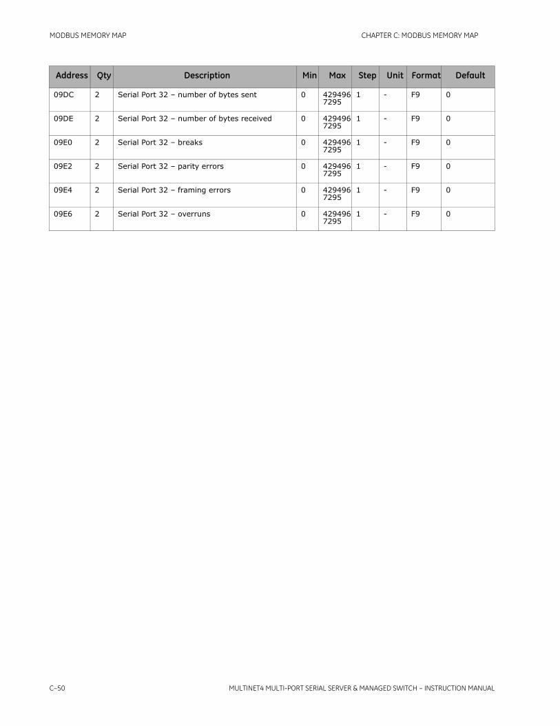
C–50 MULTINET4 MULTI-PORT SERIAL SERVER & MANAGED SWITCH – INSTRUCTION MANUAL
MODBUS MEMORY MAP CHAPTER C: MODBUS MEMORY MAP
09DC 2 Serial Port 32 – number of bytes sent 0 4294967295
1 - F9 0
09DE 2 Serial Port 32 – number of bytes received 0 4294967295
1 - F9 0
09E0 2 Serial Port 32 – breaks 0 4294967295
1 - F9 0
09E2 2 Serial Port 32 – parity errors 0 4294967295
1 - F9 0
09E4 2 Serial Port 32 – framing errors 0 4294967295
1 - F9 0
09E6 2 Serial Port 32 – overruns 0 4294967295
1 - F9 0
Address Qty Description Min Max Step Unit Format Default

MULTINET4 MULTI-PORT SERIAL SERVER & MANAGED SWITCH – INSTRUCTION MANUAL 1–1
Multinet4 Multi-Port Serial Server & Managed Switch
Chapter 1: Glossary
Digital EnergyMultilin
Glossary
This glossary contains brief explanations of acronyms and other terms used in this manual.
Term Definition
3DES Triple Data Encryption Standard (DES). A more secure version of the DES standard in which data is encrypted three times.
802.1p An IEEE standard that provides Quality of Service (QoS) at the layer 2 level.
AES Advanced Encryption Standard. A NIST-standard cryptographic cipher that uses a block length of 128 bits and key lengths of 128, 192 or 256 bit.
ANSI American National Standards Institute.
ARP Address Resolution Protocol. Enables discovery of a device’s MAC address when only its IP address is known.
AS Autonomous System. A set of routers under a single technical administration with an apparently coherent interior routing plan.
ASCII American Standard Code for Information Interchange.
BPV Bipolar violation.
BPDU Bridge Protocol Data Units. Message units that carry the Spanning Tree Protocol information.
CBT Core Based Trees. One of the communications protocols of the Internet Protocol Suite. Builds and maintains a shared delivery tree for a multicast group.

1–2 MULTINET4 MULTI-PORT SERIAL SERVER & MANAGED SWITCH – INSTRUCTION MANUAL
GLOSSARY CHAPTER 1: GLOSSARY
CCITT Comité consultatif international téléphonique et télégraphique. An institution to coordinate telecommunication standards. Although the CCITT acronyms is still widely used the institution has been known since 1992 as ITU Telecommunication Standardization Sector (ITU-T).
CHAP Challenge-Handshake Authentication Protocol. A method of authentication of remote clients used by Point to Point Protocol (PPP) servers and based on a shared secret.
CIDR Classless Inter-Domain Routing. A CIDR address is written with a forward slash preceding a suffix indicating the number of bits in the prefix length, such as 192.168.0.0/16.
CIR Committed Information Rate. A guaranteed data rate negotiated with a carrier.
CFX Configuration XML File.
DCE Data Communications Equipment. Typically a communication device such as a modem. In an RS-232 link a DCE communicates with a DTE.
DDS Digital Data Service. A private line digital service from carriers other than AT&T.
DES Data Encryption Standard (DES). A NIST-standard cryptographic cipher that uses a 56-bit key.
DHCP Dynamic Host Configuration Protocol.
DiffServ DIFFerentiated SERVices. A type of Quality of Service (QoS) functionality.
DLCI Data Link Connection Identifier. An identifying number for a private or switched virtual circuit in a frame relay network.
DSCP Differentiated Services Code Point. A value in the DiffServ portion of an IP packet header used for classification purposes.
DSR/DTR Data Set Ready/Data Terminal Ready. RS-232 handshake signals sent from the modem to the terminal (DSR) or from the terminal to the modem (DTR) indicating readiness to accept data.
DTE Data Terminal Equipment. Typically a computer system. In an RS-232 link a DTE communicates with a DCE.
EGP Exterior Gateway Protocol. An internet routing protocol.
ESP Encapsulation Security Payload. An IPSec header extension for supporting security services.
FCS Frame Check Sequence. Extra characters added to a Frame for error detection and correction.
FEFI Far End Fault Indication.
Term Definition

CHAPTER 1: GLOSSARY GLOSSARY
MULTINET4 MULTI-PORT SERIAL SERVER & MANAGED SWITCH – INSTRUCTION MANUAL 1–3
GGP Gateway to Gateway Protocol. One of the communications protocols of the Internet Protocol Suite. Used mainly for routing datagrams.
HMI Human Machine Interface. The device that enables a person to monitor and control a machine. Typically the HMI is a computer.
HTTP HyperText Transfer Protocol.
ICMP The Internet Control Message Protocol. One of the communications protocols of the Internet Protocol Suite. Chiefly used to convey error messages.
IDRP Inter-Domain Routing Protocol.
IED A microprocessor-based device that controls power system equipment such as circuit breakers and voltage regulators.
IEEE Institute of Electrical and Electronics Engineers
IGP Interior Gateway Protocols. A set of routing protocols used within a system.
IGMP Internet Group Management Protocol. One of the communications protocols of the Internet Protocol Suite. Used to manage membership in multicast groups.
IKE Internet Key Exchange. The protocol used to set up a Security Association in the IPsec protocol suite.
IP Internet Protocol.
IPIP IP in IP encapsulation. One of the communications protocols of the Internet Protocol Suite. Encloses an inner IP header with an outer header for tunneling.
ISO-IP ISO Internetworking Protocol. A network layer protocol in an OSI network.
ITU-T See CCITT.
LMI Local Management Interface. A signaling standard used between routers and frame relay switches.
LSA Link State Advertisement. An OSPF data structure that describes a portion of an OSPF network.
LSC Last Schema Change.
MAC Media Access Control. A MAC address is a unique identifier attached to most forms of networking equipment.
MD5 Message-Digest algorithm 5. A common cryptographic hash function.
MIB Management Information Base. A database used by SNMP to manage devices such as switches and routers in a network.
Term Definition

1–4 MULTINET4 MULTI-PORT SERIAL SERVER & MANAGED SWITCH – INSTRUCTION MANUAL
GLOSSARY CHAPTER 1: GLOSSARY
Modbus A communications protocol using master/slave architecture. A commonly available means of connecting industrial electronic devices.
NAPT See NAT.
NAT Network Address Port Translation. A method of using a single public IP address to provide internet access to multiple private IP addresses.
NNI Network to Network Interface.
NSSA Not So Stubby Area is an OSPF area with a limited ability to import external routes and transmit them to the OSPF backbone.
OSPF Open Shortest Path First. A routing protocol to determine the best path for traffic over a TCP/IP network.
PAP Password Authentication Protocol. An authentication protocol using unencrypted ASCII passwords over a network.
Path Cost A Spanning Tree parameter that measures how close bridges are to one another. It takes into account the bandwidth of the links between bridges.
PEM Privacy Enhanced Mail File format. A standard for secure e-mail on the Internet.
PFS Perfect Forward Secrecy. A property of public key cryptography whereby the compromise of one key does not lead to the compromise of any other keys.
PoE Power over Ethernet. A technology for delivering power (along with data) to remote devices over the twisted pair cabling of an Ethernet network.
PVC A point-to-point connection that is established before its first use and maintained regardless of the level of activity.
PVID Port VID. A user configurable parameter that associates a native VLAN with a port. Each port is assigned exactly one PVID. By default, each port is assigned PVID 1.
QoS Quality of Service. Technology and techniques, such as prioritization, to ensure the predictable handling of specified kinds of traffic.
RADIUS Remote Authentication Dial-In User Service. An AAA (authentication, authorization and accounting) protocol using a challenge/response method for authentication.
RC4 A stream cipher commonly used with SSL and in wireless networks.
RIP Routing Information Protocol. An Interior Gateway Protocol (IGP) routing protocol used on internal networks. It determines a route based on the smallest hop count between source and destination. It has a limit of 15 hops.
Term Definition

CHAPTER 1: GLOSSARY GLOSSARY
MULTINET4 MULTI-PORT SERIAL SERVER & MANAGED SWITCH – INSTRUCTION MANUAL 1–5
RS-232 A popular standard for passing serial binary data point-to-point between digital systems. Also known as EIA-232. Compare to RS-485.
RS-485 A standard for passing serial data in point-to-point or multipoint configurations among digital data systems. Also known as EIA-485. Less common but more versatile than RS-232.
RSA Rivest-Shamir-Adleman key. A two-part key. The private key is kept by the owner; the public key is published.
RSTP Rapid Spanning Tree Protocol. RSTP is a protocol that prevents loops in bridged LAN environments. It also provides for fast recovery from link failures. This product supports RSTP as specified in IEEE 802.1D (2004).
RSVP Resource reSerVation Protocol. One of the communications protocols of the Internet Protocol Suite. Used to support Quality of Service (QoS) flows.
RTS/CTS Request to Send/Clear to Send. RS-232 flow control signals sent by transmitting stations (RTS) and receiving stations (CTS).
RTU Remote Terminal Unit. A device that collects data from data acquisition equipment and sends it to the main system over a network.
SA Security Association. In IPSec an SA defines a secure, unidirectional communication channel between two entities.
SADB Security Association Database. An IPSec database containing security information specific to particular connections.Compare to SPD.
SFP Small Form-factor Pluggable Transceiver. A full-duplex serial interface converter that converts electrical signals to optical signals to run over fiber.
SHA-1 Secure Hash Algorithm 1. A common cryptographic hash function.
SNMP Simple Network Management Protocol. A network monitoring and control protocol.
SNTP Simple Network Time Protocol.
SPD Security Policies Database. An IPSec database containing security policies general to the device. Compare to SADB.
SPI Security Parameters Index. A value added to the header in IPSec tunneling that identifies a session and its encryption properties.
SSH Secure SHell. A network protocol using public key cryptography to provide secure remote login.
SSL Secure Socket Layer. A cryptographic protocol that creates a secure data transfer session over a standard TCP connection.
Term Definition

1–6 MULTINET4 MULTI-PORT SERIAL SERVER & MANAGED SWITCH – INSTRUCTION MANUAL
GLOSSARY CHAPTER 1: GLOSSARY
Station Cache A database maintained by the Ethernet bridge that tracks MAC addresses of stations on the network and the ports associated with them.
Syslog A protocol for sending event messages over an IP network to remote servers called "event message collectors."
T1/E1 T1 is a widely-used T-carrier telecommunications standard capable of transmitting 1.544 Mbits/second. The T1 designation is used in North America. The analogous system outside of North America is called E1.
TCP Transmission Control Protocol.
TLS Transport Layer Security.
UDP User Datagram Protocol. One of the communications protocols of the Internet Protocol Suite. Replaces TCP when a reliable delivery is not required.
URL Uniform Resource Locator.
VID VLAN Identifier.
VLAN Virtual Local Area Network. A logical subgroup within a local area network that is created with software rather than by physically manipulating cables.
WAN Wide Area Network.
WFQ Weighted Fair Queueing. A packet scheduling technique that enables several data flows to use the same link.
X.509 An X.509 certificate is a message that contains an entity's credentials. Information such as the entity's name, organization, and contact information are included.
XML eXtensible Markup Language
XON/XOFF A software flow control protocol in which a receiver sends an XOFF character to a transmitter to signal that it is unable to receive data and an XON character to signal that it is able to receive data.
Term Definition