instruction manual (europe, middle east, and africa)
TRANSCRIPT

Summary
Introduction ................................................................... 1
Description.................................................................... 1
Characteristics .............................................................. 2
Labelling ....................................................................... 3
Spare Parts................................................................... 4
Operation ...................................................................... 6
Dimensions and Weights .............................................. 7
Installation .................................................................... 8
Commissioning ............................................................. 9
Maintenance ................................................................. 10
Introduction
The Type EZR is a pilot-operated regulator used in transmission and distribution networks or pipe lines supplying industries and commercial businesses.
The Type EZR can be equipped with a slam shut Type OS2 (Type EZR body change) which permits the gas flow to be cut off rapidly and totally in the case of under or over outlet regulator pressure.
Description
The Type EZR consists of:A version without integral slam shut:• A body («E body» type), a bonnet• A regulation subassembly consisting of a slotted cage and
a diaphragm/plug• A travel indicator, an inlet screen• A pilot assembly consisting of a filter with bleeding screw
(filtration 20 microns), an adjustable restrictor and a pilot set to the required outlet pressure
Pilot-Operated Regulator
Figure 1. Type EZR Pilot-Operated Regulator
A version with integral slam shut:• A body («X body» type), a bonnet, a connecting part• A regulation subassembly consisting of a slotted cage
and a diaphragm/plug• A travel indicator• A pilot assembly consisting of a filter with bleeding screw
(filtration 20 microns), an adjustable restrictor and a pilot adjusted to the required outlet pressure
• A removable slam shut orifice• A integral O-ring tightshut valve/bypass assembly• A release relay Type OS2 according to D103683X012_
OS2_IM: - a mechanism box (BM) - a safety manometric box (BMS) to be connected outlet
side of the regulator
The Type EZR is in conformity with the PED 2014/68/EU and is classified in Category IV.
Type EZRInstruction ManualD103681X012
December 2017
Eur
ope,
Mid
dle
Eas
t and
Afri
ca O
nly

Material RegulatorBody SteelBonnet SteelSlotted disc Stainless steelDiaphragm, O-rings Nitrile (NBR)Slam shutConnecting part SteelOrifice Stainless steelValve plug Stainless steelPilotBody Stainless steelManometric box Stainless steel or AluminiumRestrictor Stainless steelFilter AluminiumCartridge Polythene
Coefficients Capacity DN 25 DN 50 DN 80 DN 100 DN 150
Cg
100% 480 1800 3400 5550 11200
60% 290 1020 1970 3300 7150
30% 140 560 970 1690 3570
C1
100% 33 36 37 38 36
60% 29 28 29 27 30
30% 30 29 26 26 26
Valve plug travel (mm) 35 35 50 50 50
Table 3. Flow Coefficients and Valve Plug Travel Information
B05a
BMP Size 1 2 3 4 5 6 7 8
Spring Colour White Yellow Black Green Blue Red Blue Red
Spring Range (bar)
0.5 1.0 2.8 5.2 9.7 13.8 24.1 31.0
1.0 2.8 5.2 9.7 13.8 24.1 31.0 48.3B05b
Table 4. Pilot Pressure Ranges
ConnectionsInlet / Outlet: ISO PN 100 B (ANSI 600 RF) ISO PN 50 B (ANSI 300 RF) ISO PN 20 B (ANSI 150 RF) Other possibilities exist (contact factory) ISO PN 16 B, 25 B, 40 BPilot Impulse line (IP): 1/4’’ NPT tappedPilot Monitor impulse line (IM): 1/4’’ NPT tappedIntermediate impulse line (PI): 1/4’’ NPT tappedSlam shut impulse line (IS): 1/4’’ NPT tappedMechanism box vent (E): 1/4’’ NPT tappedImpulse diameter: Pipe interior Ø 8/10mm min.
Operating pressure PS 72.4 bar(1) SLAM SHUTOperating temperature TS -17 / 66°C(1)
Accuracy AG2.5
REgULATOR 5 (Piston)Outlet pressure Pa 0.5 to 48.3 bar Set point range Pt up to 100 barMinimum differential ∆P min 2 to 3 bar PILOT
Maximum operating differentialPN 20
∆P max18.6 bar Type of pilot Standard 161EB
PN 50 50.0 bar Monitor 161EBMPN 100 55.2 bar Manometric box PS BMP 52 bar
Max emergency differential ∆P emerg 72.4 barFluid
Groups 1 and 2 according to PED 97/23/EC 1st and 2nd family gas according to EN 437 or other gases (compressed air, nitrogen). The gas must be noncorrosive, clean (filtration on inlet side necessary) and dry.Accuracy AC 2.5 - 5
1. Values correspond to the characteristics of the regulator diaphragm.
Table 1. General Characteristics for Type EZR Regulator
B05c
Body Pmax (bar) Tmin (°C) Tmax (°C)
A216WCB 96.7 -20 71
A352LCC 100 -30 71
The regulator body and the slam shut have been designed to support different pressure and temperature levels
Table 2. Pressure and Temperature Characteristics
CHARACTERISTICS
Type EZR
2
Eur
ope,
Mid
dle
Eas
t and
Afri
ca O
nly
PN
PTPS
Pumax20
18.6
18.632
ReductionCg See Table 3
0062(Gaz Naturel)
28320 Gallardon-France
REGULATEUR/REGULATOR
IV
EZR -
SECURITE/SLAM-SHUT
GROUPE 1
N°sérieserialDate Fab/TestMfg/Test date
Cat PS
normestandardnormestandard
EN 334 mode défaillancefailure modeclasse sécuritéslam shut class
DN PN
Pumax bar
FISHERFRANCEL
PT bar Temp TS -17/+66°C -Class Type Cg
matériaushell A352LCC+A350LF2
OS2 -
Standard EN 14382 -
BMS 027/017 BMS 162BMS 236/315 BMS 071
Min only AllMax-Min typesofBMS
SecurityClassA B
BMS Setting
DN 25 50 80 100
20B1 50B1 100B2 16B 25B 40BOther configurations available (contact factory)
DDMMYEAR
bar
Max only
Depending on BMS con�guration
-
150
PN
100% 60% 30%
50
507950
100
72.411472.4
16
162616
25
254025
40
406340
E04a
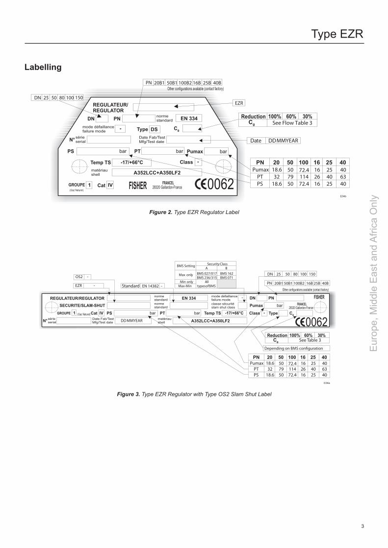
Figure 3. Type EZR Regulator with Type OS2 Slam Shut Label
0062(Gaz Naturel)
28320 Gallardon-France
REGULATEUR/REGULATOR
IVGROUPE 1
N° sérieserialDate Fab/TestMfg/Test date
Cat
PS
normestandard EN 334
mode défaillancefailure mode
DN PN
Pumax bar
FISHER FRANCEL
PT bar
Temp TS -17/+66°C -Class
DSType Cg
matériaushell A352LCC+A350LF2
bar
Other configurations available (contact factory)
EZR
Date DDMMYEAR
DN 25 50 80 100
-
150
20B1 50B1 100B2 16B 25B 40BPN
PN
PTPS
Pumax20
18.6
18.632
ReductionCg See Flow Table 3
100% 60% 30%
50
507950
100
72.411472.4
16
162616
25
254025
40
406340
Labelling
Figure 2. Type EZR Regulator Label
E04b
Type EZR
3
Eur
ope,
Mid
dle
Eas
t and
Afri
ca O
nly

Spare Parts
Type 161EB Type 161EBH
Type 161EBM Type 161EBHM
Figure 4. Types 161EB, 161EBH, 161EBM and 161EBHM Pilots
B08
19
18
Figure 5. Filter
B09
17
Figure 6. Adjustable Restrictor
B06
B11
Description Key
Reference
Pilot Type
161EB 161EBH 161EBM 161EBHM
Pilot kit 0.34 to 13.8 bar 15 R161X000012 - - - - - - - - - - - R161MX00012 - - - - - - - - - - -
Pilot kit 13.8 to 24.1 bar 15 R161X000022 - - - - - - - - - - - R161MX00022 - - - - - - - - - - -
Pilot kit EBH(M) 16 - - - - - - - - - - - R161HX00012 - - - - - - - - - - - R161HMX0012
O-ring 17 - - - - - - - - - - - 1C8538X0052 - - - - - - - - - - -
Filter cartridge 18 - - - - - - - - - - - 17B6813X012 - - - - - - - - - - -
O-ring 19 - - - - - - - - - - - 1F269206992 - - - - - - - - - - -
SAV kit 0.34 to 13.8 bar(1) - - - - 197435 - - - - - - - - - - - 197438 - - - - - - - - - - -
SAV kit 13.8 to 24.1 bar(1) - - - - 197436 - - - - - - - - - - - 197439 - - - - - - - - - - -
SAV kit 24.1 to 48.3 bar(1) - - - - - - - - - - - - - - - 197437 - - - - - - - - - - - 197440
1. The SAV kits include item numbers 15 or 16, 17, 18 and 19.
BMP Size Spring Reference
1 17B1260X012
2 17B1262X012
3 17B1259X012
4 17B1261X012
5 17B1263X012
6 17B1264X012
7 17B1263X012
8 17B1264X012
To pass from 0.5 to 13.8 bar or from 24.1 to 48.3 bar the spring must be changed.
Table 5. Pilot, Restrictor and Filter Spare Parts List
Type EZR
4
Eur
ope,
Mid
dle
Eas
t and
Afri
ca O
nly

Spare Parts
Regulator, Type EZR
Description Key
Reference
DN / in.
25 / 1 50 / 2 80 / 3 100 / 4 150 / 6
withslam shut
O-ring 1 400009 400024 400091 400045 400262
O-ring 2 19B2838X012 18B2124X012 18B8514X012 18B2140X012 19B0359X012
Guide 3 401950 401951 401952 401953 401954
O-ring 4 400527 400263 400258 400260 400261
Bypass 5 180977 180977 180977 180977 180977
SAV kit PN 20 1 to 14 197421 197422 197424 197425 197427
SAV kit PN 50/100 1 to 14 197421 197423 197424 197426 197427
without slam shut
SAV kit PN 20 6 to 14 197428 197429 197431 197432 197434
SAV kit PN 50/100 6 to 14 197428 197430 197431 197433 197434
with/withoutslam shut
O-ring 6 18B3438X012 18B3438X012 10A8931X012 10A8931X012 10A3800X012
O-ring 7 1H2926X0032 1H2926X0032 1D191706992 1D191706992 1D191706992
O-ring 8 13A1584X052 13A1584X052 10A3803X062 10A3803X062 T12050X0012
O-ring 9 19B2838X012 18B2124X012 18B8514X012 18B2140X012 19B0359X012
PN 20 diaphragm 10 39B2397X012 29B2715X022 39B2726X012 38B5965X012 49B0357X012
PN 50/100 diaphragm 10 39B2397X012 28B2123X052 39B2726X012 39B3996X012 49B0357X012
O-ring 11 13A1584X052 13A1584X052 10A3803X062 10A3803X062 T12050X0012
O-ring 12 1E216306992 1E216306992 1J4888X0052 1J4888X0052 11A8741X052
O-ring 13 14A5713X012 10B4428X012 10B4366X012 10B4373X012 1H862306992
O-ring 14 - - - - - - - - - - - - - - - - - - - - - - - - - - - - - - - - - - - - - - - - - - - - 1D269206992
Safety manometric box - - - - See D103683X012_OS2_IM manual
Table 6. Types EZR and EZR-OS2 Spare Parts List
B13
5
6
7
8
9
10
11
12
13
14
4
3
2
1
B12
Figure 7. Types EZR and EZR-OS2 Spare Parts
Type EZR
5
Eur
ope,
Mid
dle
Eas
t and
Afri
ca O
nly

Operation
Regulator
The Type EZR is a pilot-driven, diaphragm/plug regulator.Tight shutoff is achieved by the diaphragm/plug pushing against the slotted cage, the force of the closing spring and the inlet pressure.• Opening As the flow increases, the outlet pressure Pd
decreases on the outlet side of the regulator and on the pilot diaphragm.
Due to the force of the spring, the pilot opens. The pilot flow increases, the pressure loss through the
pilot restrictor increases. The modulated pressure Pm decreases. The force of the closing spring and that of the Pm
becomes inferior to that provoked by the Pu, the regulator OPENS.
• Closing As the flow decreases, the Pd increases outlet side of
the regulator. The force of the pilot diaphragm is overcome by the force
of the spring, the pilot closes.
The pressure loss through the pilot restrictor decreases. The force of the closing spring and that of the Pm
becomes superior to that provoked by the Pu, the regulator CLOSES.
Slam Shut
The pressure of the zone to be protected (generally the pipeline on the outlet side of the regulator and after the slam shut) is sensed by the safety manometric box (BMS).If the pressure exceeds the set tripping pressure, the release relay frees the valve plug. Due to the force of the closing spring and the fluid (trying to close), the valve plug closes on the orifice. The gas flow is obstructed until the fault has been corrected and the mechanism box manually rearmed.To reopen the valve plug an equal pressure balance on inlet and outlet sides of the regulator is required. The mechanism box is rearmed after opening the internal bypass.Rearming and balancing are achieved at the same time.
B18
Figure 8. Type EZR Operational Schematic
INLET PRESSUREMODULATED PRESSUREOUTLET PRESSURE
Type EZR
6
Eur
ope,
Mid
dle
Eas
t and
Afri
ca O
nly

Dimensions and Weights
Table 11. Dimensions (mm) - Types EZR and EZR-OS2 (part 2)
B17a
Body DNA
D J MPN16 20 25 40 50 100
25 193.5 184 193.5 193.5 197 210 165 68 5450 254 254 267 267 267 286 165 68 5480 310 298 317 317 317 337 181 95 54
100 350 352 368 368 368 394 187 95 54150 451 451 473 473 473 508 249 95 54
Body DN B C E H
25 233 315 348 250
50 243 330 357 265
80 361 366 410 301
100 393 410 454 345
150 423 396 468 332
Table 7. Dimensions (mm) - Type EZR-OS2 (part 1)
B15b
Body DN PN 20 PN 50 PN 100
25 20 21 22
50 39 41 43
80 63 69 71
100 104 113 123
150 192 211 244
Table 8. Weights (kg) - Type EZR-OS2
B16b
Body DN B C E
25 220 62 335
50 226 83 340
80 343 105 392
100 372 137 433
150 420 178 465
Table 9. Dimensions (mm) - Type EZR (part 1)
B15a
Body DN PN 20 PN 50 PN 100
25 12 14 16
50 26 27 31
80 50 51 57
100 67 73 88
150 97 108 161
Table 10. Weights (kg) - Type EZR
B16a
Table 12. Dimensions (mm) - BMS (Safety Manometric Box)
B17b
Type F g
Diaphragm 162 181
Piston 71 204
Bellows 74 223
M
J
E
B
C
A
D
B14b
Figure 10. Dimensions (mm) - Type EZR
CNALBFERME
=
=ETIHWCL SO
DE
CNALBFERME
=
= ETI HW
CLSO
DE
C
G
H
A
B
F
D
E
25 Disassembly
M
J
B14a
Figure 9. Dimensions (mm) - Type EZR-OS2
Type EZR
7
Eur
ope,
Mid
dle
Eas
t and
Afri
ca O
nly

Installation
• The regulator is installed on horizontal pipeline. Version with slam shut, the release relay is situated towards the bottom (see schematic).
• Installation according to EN12186 recommended.• Installaccordingtodirectionoffluidflow(arrow).• When assembling with adjacent elements care
must be taken not to create pressure force on the body and the assembling elements (bolts, O-rings, flanges)shouldbecompatiblewiththegeometryandworking conditions of the equipment.
• If the case arises a support must be used to avoid pressure force on the body (a support can be installed undertheflanges).
• Version with integral slam shut , connect the safety manometric box (IS) to the impulse at 4D on a straight run of the outlet pipe.
• It is recommended to separate the slam shut impulse line (IS) from that of the pilot (IP). Do not connect the impulses on the lower generator line.
• It is recommended to install an isolation valve and an atmospheric valve, which can be useful for slam shut trippingandverifications.
• Nomodificationshouldbemadetothestructureofthe equipment (drilling, grinding, soldering...).
• It is recommended to install a servicing valve on the outlet pipeline to facilitate adjustments and bleeding off to the atmosphere.
• Verify that the inlet side is protected by an appropriate device(s) to avoid exceeding the limits of utilization (PS, TS).
• Verify that the limits of utilization correspond to the appropriate operating conditions.
• Version with integral slam shut, verify that the safety manometric box (BMS) and spring correspond to the appropriate operating conditions on the outlet side of the regulator.
• The equipment should not receive any type of shock, especially the release relay.
• The user should verify or carry out a protection adapted to the environment.
• Fire, seismic and lightening are not taken into consideration in standard regulators. If required, a specialproductselectionand/orspecificcalculationsmaybesuppliedaccordingtospecificrequirements.
• Version without integral slam shut, verify that a pressure limiting device on the outlet side of the regulator guarantees a pressure limit inferior or equal to the pilot PS.
Allinterventionsontheequipmentshouldonlybeperformedbyqualifiedandtrainedpersonnel.
! WARNINg ! WARNINg
B19
Figure 11. Type EZH Installation Configurations
Type EZR
8
Eur
ope,
Mid
dle
Eas
t and
Afri
ca O
nly

• Servicing valve Open slightly
• Pilot Screw to set outlet pressure
• Outlet valve Open slowly
• Restriction Set to "RUN" by successive fractions 2, 4 or 6
• Servicing valve Closed
The equipment is commissioned
It is recommended to seal the release relay
Commissioning
Operations concerning the integral slam shut version are in italic.
All interventions on equipment should only be performedbyqualifiedpersonnel
PreliminaryVerifications
Start-up positions• Inlet and outlet valves Closed
Verify the absence of pressure between inlet and outlet valves
• Slam shut valve plug Closed
• Pilot A Unloaded
• Restriction B START position
Slamshutsetpointverification
Using the atmospheric valve, inject a pressure equal to the pressure required for the regulator
• 1st release relay stage Set (Stage 1)
• Slam shut valve plug Open (Stages 2 and 3)
Progressively increase the pressure to reach tripping
Adjust setting if necessary (D103683X012_OS2_IM) Note the set point value on the equipment or mark it on a commissioning document
Positions before commissioning• Impulse line isolating valve Open
• Impulse line atmospheric valve Closed
• Slam shut valve plug Closed
• Servicing valve Closed
The equipment is ready for commissioning
Commissioning (Act slowly)
• Inlet valve Open very slowly
• 1st release relay stage Set (Stage 1)
• Slam shut valve plug Bypass (Stage 2)
Open (Stage 3)
Triggeredposition
B20
Stages 2 and 3Stage 1
Figure 13. Setpoint Verification Phase
B22
Figure 12. Type EZH-OS2 Regulator
INLET PRESSUREMODULATED PRESSUREOUTLET PRESSURE
Type EZR
9
Eur
ope,
Mid
dle
Eas
t and
Afri
ca O
nly

Maintenance
Operations concerning the integral slam shut version are in italic.
Servicing Check
Recommended frequency:
• Twice yearly minimum
Verification:
• Set point verification• Regulator valve plug tightness• Tripping and set point value• Slam shut valve tightness
Departure positions
• Inlet valve Open• Outlet valve Open• Slam shut valve plug Open• Regulator In operationInlet and outlet sides of regulator under pressure
Tightshutverification(and tripping verification for integral slam shut versions)
• Inlet valve Closed• Outlet valve Closed• Regulator Observe the evolution of the outlet
pressure (control regulator tightness)
Filterverification
• Purge the filter C• Verify the cartridge
If the outlet pressure increases Internal leak Control the regulator valve plug Control the regulator orifice Control the pilot or contact after-sales If the outlet pressure decreases External leak Locate and seal the leak or contact after-sales
If the outlet pressure is constant The regulator is tightshut Increase the set point until tripping occurs (without exceeding the outlet limits) If the slam shut valve plug will not close Operating fault Control the release relay Control the slam shut valve plug or contact after-sales
If the slam shut valve plug closes Operating correctly Observe the evolution of the outlet pressure (control tightness)
If the outlet pressure is constant Purge the outlet side of the regulator Observe the evolution of the outlet pressure (control tightness)
If the outlet pressure increases Internal leak Control the slam shut valve plug Control the slam shut orifice Control the bypass or contact after-sales
If the outlet pressure is constant Slam shut valve plug is tightshut
Table 12. Troubleshooting for Types EZR and EZR-OS2 Regulators
Type EZR
10
Eur
ope,
Mid
dle
Eas
t and
Afri
ca O
nly

DisassemblyRecommended frequency: Every 2 to 6 years (or less depending on operating conditions)
Verification: Condition of O-rings, diaphragms, lubrication
Replacement: O-rings, diaphragm
Tools: Dimensions according to tables below
Preliminary Operations• Valve plug closed• Inlet and outlet valves closed• Bleedoffoutletpressure• Bleedoffinletpressure• Unscrew the pilot impulse connection• Unscrew the screws (key 1) fixing the bonnet (key 2)• Remove the bonnet (key 2)• Remove the diaphragm/plug assembly (key 3)
Maintenance (continued)
• Remove the slotted cage (key 4), the O-ring (key 5), the strainer (key 6) (or the space washer (key 6))
• Clean parts and replace them if necessary
Pilot• Unscrew the manometric box screws• Remove the diaphragm
Slam Shut (Version with slam shut)• Unscrew the BMS impulse line connector (IS)• Remove the BM cover (key 7)• Unscrew the BM fixing screw (key 8)• Remove the holding pin (key 10)• Remove the BM (key 9)• Unscrew the screws (key 11) from the connecting part
(key 12)• Remove the connecting part (key 12)• Remove the spring (key 13) and the valve plug (key 14)• Unscrew the bypass (key 15)• Unscrew the screws CHC (key 16) (DN 100 and 150)Removing the orifice (key 17) (not recommended) requires a special extraction tool
B24
Figure 14. Type EZR-OS2
B25a
Body DN / In.
Screw keys 1 and 11
Spanner, in.
Screw keys 1 and 11
Torque N.m.
Fixation keys 18
Connector key 19
Bypass key 15
25 / 1 9/16 - 12 x 1 3/4 13/16 110 8 130 14
50 / 2 1/2 - 13 x 1 1/2 3/4 110 9 130 14
80 / 3 5/8 - 11 x 1 3/4 15/16 175 28 280 20
100 / 4 3/4 - 10 x 2 1/4 1 1/8 260 28 280 24
150 / 6 1 - 8 x 2 3/4 1 1/2 510 70 410 24
B25b
Table 13. Torque Specifications
Type EZR
11
Eur
ope,
Mid
dle
Eas
t and
Afri
ca O
nly

Reassembly• Perform the above operations in reverse order (respect
tightening torques)• Replace the O-rings and diaphragm at each disassembly
Slam Shut Reassembly (Version with slam shut)• The valve plug should be held in an upper position using
a packing gland and a box to facilitate reassembly• Precaution must be taken concerning the passage of the
valve plug over the segments
Maintenance (continued)
• Lubricate screws before tightening• Lightly lubricate the O-rings (silicone grease) except for
the valve plug O-ring• Lightly lubricate the stem (silicone grease)• Lubricate the release relay mechanism (yoke and bolt) (molybdenum graphite grease)• Lubricate the BMS spring (molybdenum graphite grease)• A special tool is required for reassembling a new orifice
Type EZR
Facebook.com/EmersonAutomationSolutions
LinkedIn.com/company/emerson-automation-solutions
Twitter.com/emr_automation
Emerson Automation SolutionsE
urop
e, M
iddl
e E
ast a
nd A
frica
Onl
yFisher.com
Americas McKinney, Texas 75070 USA T +1 800 558 5853
+1 972 548 3574
Europe Bologna 40013, Italy T +39 051 419 0611
Asia Pacific Singapore 128461, Singapore T +65 6770 8337
Middle East and Africa Dubai, United Arab Emirates T +971 4 811 8100
D103681X012 © 2009, 2017 Emerson Process Management Regulator Technologies, Inc. All rights reserved. 12/17. The Emerson logo is a trademark and service mark of Emerson Electric Co. All other marks are the property of their prospective owners. Fisher™ is a mark owned by Fisher Controls International LLC, a business of Emerson Automation Solutions.
The contents of this publication are presented for information purposes only, and while effort has been made to ensure their accuracy, they are not to be construed as warranties or guarantees, express or implied, regarding the products or services described herein or their use or applicability. All sales are governed by our terms and conditions, which are available on request. We reserve the right to modify or improve the designs or specifications of our products at any time without notice.
Emerson Process Management Regulator Technologies, Inc does not assume responsibility for the selection, use or maintenance of any product. Responsibility for proper selection, use and maintenance of any Emerson Process Management Regulator Technologies, Inc. product remains solely with the purchaser.