instruction manual bench lathe model pm … · instruction manual bench lathe ... gear box 8....
TRANSCRIPT
1
INSTRUCTION MANUAL BENCH LATHE
MODEL PM-1228VF-LB
BEFORE USING BE SURE READ THIE MANUAL CAREFULLY -PM-1228VF-LB-

2
3
Table of Contents INTRODUCTION......................................................................................................................4 MAIN PARAMETERS……………………………………………………………………......5 SECTION 1: SAFETY...............................................................................................................7 SECTION 2: POWER SUPPLY...............................................................................................9 Availability………………………………………………………………………9 Circuit Requirements…………………………………………………………..9 Grounding & Plug Requirements…………………………………………….10 Extension Cords……………………………………………………………….10 SECTION 3: SETUP……………………………………………………………………...…11 Unpacking……………………………………………………………………...11 Inventory………………………………………………………………………11 Clean Up……………………………………………………………………….12 Installation Dimensions……………………………………………………….12 Check Gearbox Oil……………………………………………………………12 Open the Cover…………………………………………………………..……13 Install belt…………………………………………...…………………………13 Test Run Lathe………………………………………………………………...14 SECTION 4: OPERATE……………………………………………………………………..15 General…………………………………………………………………………15 Controls…………………………………………………………...……………15 Removing/Installing Chuck or Faceplate…………………………………...16 Dead Centers…………………………………………………………………..17 Tailstock Positioning…………………………………………………………..18 Changing Tool Posts…………………………………………………………..18 Cross Slide…………………………………………………………………......18 Compound Slide……………………………………………………………….19 Carriage Handwheel…………………………………………………………..20 Half Nut Lever…………………………………………………………………20 Carriage/Cross Feed Lever…………………………………………...………20 Carriage Lock………………………………………………………………….20 Gearbox Levers………………………………...……………………………...20 Threads and Change gears……………………………………………………22 Left threads and reverse cutting feed………………………………………...22 Clutch Overload…………………………………………………...…………..23 SECTION 6: MAINTENANCE……………………………………………………….……..24 Lubrication…………………………………………………………………….25 Gibs…………………………………………………………………………….26 Bearing Preload……………………………………………………………….27 WIRING DIAGRAM……………………………………………...…………………………29 PARTS LIST………………………………………………………………………………….30
4
IDENTIFICATION
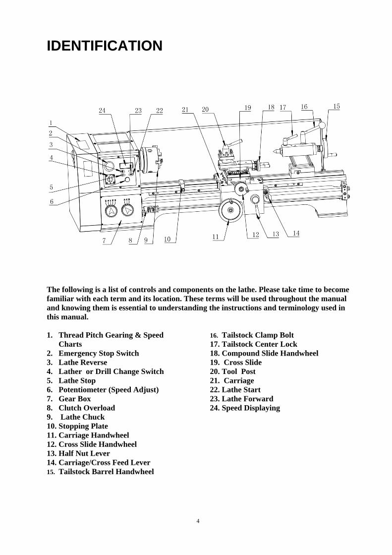
The following is a list of controls and components on the lathe. Please take time to become familiar with each term and its location. These terms will be used throughout the manual and knowing them is essential to understanding the instructions and terminology used in this manual. 1. Thread Pitch Gearing & Speed
Charts 2. Emergency Stop Switch 3. Lathe Reverse 4. Lather or Drill Change Switch 5. Lathe Stop 6. Potentiometer (Speed Adjust) 7. Gear Box 8. Clutch Overload 9. Lathe Chuck 10. Stopping Plate 11. Carriage Handwheel 12. Cross Slide Handwheel 13. Half Nut Lever 14. Carriage/Cross Feed Lever 15. Tailstock Barrel Handwheel
16. Tailstock Clamp Bolt 17. Tailstock Center Lock 18. Compound Slide Handwheel 19. Cross Slide 20. Tool Post 21. Carriage 22. Lathe Start 23. Lathe Forward 24. Speed Displaying
5
Main Parameters
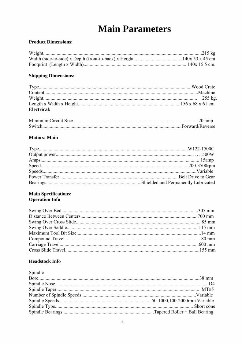
Product Dimensions: Weight..................................................................................................................................215 kg Width (side-to-side) x Depth (front-to-back) x Height........................................140x 53 x 45 cm Footprint (Length x Width).................................................................................... 140x 15.5 cm. Shipping Dimensions: Type.............................................................................................................................Wood Crate Content..............................................................................................................................Machine Weight.............................................................................................................................. 255 kg. Length x Width x Height....................................................................................156 x 68 x 61.cm Electrical: Minimum Circuit Size................................................................. ............. ............. ........ 20 amp Switch..................................................................................................................Forward/Reverse Motors: Main Type..........................................................................................................................W122-1500C Output power................................................................................................................. …1500W Amps.......................................................................................... ............. ............. ........... 15amp Speed.........................................................................................................................200-3500rpm Speeds..............................................................................................................................Variable Power Transfer .................................................................................................Belt Drive to Gear Bearings..............................................................................Shielded and Permanently Lubricated Main Specifications: Operation Info Swing Over Bed................................................................................................................305 mm Distance Between Centers................................................................................................700 mm Swing Over Cross Slide.......................................................................................................85 mm Swing Over Saddle............................................................................................................115 mm Maximum Tool Bit Size......................................................................................................14 mm Compound Travel............................................................................................................... 80 mm Carriage Travel..................................................................................................................600 mm Cross Slide Travel..............................................................................................................155 mm Headstock Info Spindle Bore....................................................................................................................................38 mm Spindle Nose..............................................................................................................................D4 Spindle Taper..................................................................................................................... MT#5 Number of Spindle Speeds..............................................................................................Variable Spindle Speeds............................................................................50-1000,100-2000rpm Variable Spindle Type................................................................................................................. Short cone Spindle Bearings...........................................................................Tapered Roller + Ball Bearing

6
Tailstock Info Tailstock Quill Travel........................................................................................................ 80 mm Tailstock Taper.....................................................................................................................MT#3 Tailstock Barrel Diameter...............................................................................................Φ38 mm Threading Info of Metric Lathe Number of Longitudinal Feeds...................................................................................................14 Range of Longitudinal Feeds...................................................................................0.03 – 0.3 mm. Number of Cross Feeds.............................................................................................................. 14 Range of Cross Feeds......................................................................................... 0.015 – 0.15 mm Number of Inch Threads.............................................................................................................. 6 Range of Inch Threads..................................................................................................12 - 80 TPI Number of Metric Threads..........................................................................................................15 Range of Metric Threads..........................................................................................0.25 - 2.5 mm Threading Info of Imperial Lathe Number of Longitudinal Feeds...................................................................................................15 Range of Longitudinal Feeds............................................................................0.0016 – 0.015 in. Number of Cross Feeds..............................................................................................................15 Range of Cross Feeds.......................................................................................0.0008 – 0.0061 in Number of Inch Threads.............................................................................................................21 Range of Inch Threads...................................................................................................5 - 72 TPI Number of Metric Threads.........................................................................................................12 Range of Metric Threads................................................................................................0.5- 4 mm Dimensions Bed Width..........................................................................................................................155 mm. Lead screw Diameter..................................................................................20 mm ( Metric Lathe). 3/4 in (Imperial Lathe) Lead screw....................................................................................................3 mm ( Metric Lathe) 8 TPI (Imperial Lathe) Lead screw Length...........................................................................................................1069 mm. Steady Rest Capacity.....................................................................................................6 – 50 mm Follow Rest Capacity.....................................................................................................6 – 50 mm Faceplate Size................................................................................................................Φ240 mm. Floor to Center Height.......................................................................................................348 mm Construction Headstock........................................................................................................................ Cast Iron Headstock Gears.....................................................................................................................Steel Bed..................................................................................................Induction Hardened Cast Iron Body.................................................................................................................................Cast Iron Paint..................................................................................................................................... Epoxy

7
SECTION 1: SAFETY READ MANUAL BEFORE OPERATING MACHINE.
FAILURE TO FOLLOW INSTRUCTIONS BELOW WILL RESULT IN PERSONAL INJURY.
Standard Safety Instructions
1. Thoroughly read the Instruction Manual before operating your machine. Learn the applications, limitations and potential hazards of this machine. Keep the manual in a safe and convenient place for future reference. 2. Keep work area clean and well lighted. Clutter and inadequate lighting invite potential hazards. 3. Ground all tools. If a machine is equipped with a three-prong plug, it must be plugged into a three-hole grounded electrical receptacle or grounded extension cord. If using an adapter to aid in accommodating a two-hole receptacle, ground using a screw to a known ground. 4. Wear eye protection at all times. Use safety glasses with side shields or safety goggles that meet the appropriate standards of the American National Standards Institute (ANSI). 5. Avoid dangerous environments. Do not operate this machine in wet or open flame environments. Airborne dust particles could cause an explosion and severe fire hazard. 6. Ensure all guards are securely in place and in working condition. 7. Make sure switch is in the OFF position before connecting power to machine. 8. Keep work area clean, free of clutter, grease, etc. 9. Keep children and visitors away. Visitors must be kept at a safe distance while operating unit. 10. Childproof your workshop with padlocks, master switches or by removing starter keys. 11. Stop and disconnect the machine when cleaning, adjusting or servicing.

8
12. Do not force tool. The machine will do a safer and better job at the rate for which it was designed. 13. Use correct tool. Do not force machine or attachment to do a job for which it was not designed. 14. Wear proper apparel. Do not wear loose clothing, neck ties, gloves, jewelry, and secure long hair away from moving parts. 15. Remove adjusting keys, rags, and tools. Before turning the machine on, make it a habit to check that all adjusting keys and wrenches have been removed. 16. Avoid using an extension cord. But if you must use one, examine the extension cord to ensure it is in good condition. Immediately replace a damaged extension cord. Always use an extension cord that uses a ground pin and connected ground wire. Use an extension cord that meets the amp rating on the motor nameplate. If the motor is dual voltage, be sure to use the amp rating for the voltage you will be using. If you use an extension cord with an undersized gauge or one that is too long, excessive heat will be generated within the circuit, increasing the chance of a fire or damage to the circuit. 17. Keep proper footing and balance at all times. 18. Lock your mobile base, if used, to prevent the machine from moving during operation. 19. Do not leave machine unattended. Wait until it comes to a complete stop before leaving the area. 20. Perform machine maintenance and care. Follow lubrication and accessory attachment instructions in the manual. 21. If at any time you are experiencing difficulties performing the intended operation, stop using the machine! Then contact our technical support or ask a qualified expert how the operation should be performed. 22. Habits—good and bad—are hard to break. Develop good habits in your shop and safety will become second-nature to you. 23. Be aware that certain metal shavings and cutting fluids may cause an allergic reaction in people and animals, especially when cutting fumes can be inhaled. Make sure you know what type of metal and cutting fluid you will be exposed to and how to avoid contamination.
9
SECTION 2: POWER SUPP LY
Availability Before installing the machine, consider the availability and proximity of the required power supply circuit. If an existing circuit does not meet the requirements for this machine, a new circuit must be installed. To minimize the risk of electrocution, fire, or equipment damage, installation work and electrical wiring must be done by a qualified electrician in accordance with all applicable codes and standards.
Full-Load Current Rating The full-load current rating is the amperage a machine draws at 100% of the rated output power. On machines with multiple motors, this is the amperage drawn by the largest motor or sum of all motors and electrical devices that might operate at one time during normal operations. Full-Load Current Rating at 110V.... 15 Amps The full-load current is not the maximum amount of amps that the machine will draw. If the machine is overloaded, it will draw additional amps beyond the full-load rating. If the machine is overloaded for a sufficient length of time, damage, overheating, or fire may result— especially if connected to an undersized circuit. To reduce the risk of these hazards, avoid overloading the machine during operation and make sure it is connected to a power supply circuit that meets the requirements in the following section.
Circuit Requirements This machine is prewired to operate on a 110V power supply circuit that has a verified ground and meets the following requirements: Voltage..........................................110V/120V Frequency..............................................60 Hz Phase...........................................Single-Phase Power Supply Circuit......................20 Amps A power supply circuit includes all electrical equipment between the breaker box or fuse panel in the building and the machine. The power supply circuit used for this machine must be sized to safely handle the full-load current drawn from the machine for an extended period of time. (If this machine is connected to a circuit protected by fuses, use a time delay fuse marked D.)
Note: The circuit requirements listed in this manual apply to a dedicated circuit—where only one machine will be running at a time. If this machine will be connected to a shared circuit where multiple machines will be running at the same time, consult a qualified electrician to ensure that the circuit is properly sized for safe operation.
10
Grounding & Plug Requirements This machine MUST be grounded. In the event of certain malfunctions or breakdowns, grounding reduces the risk of electric shock by providing a path of least resistance for electric current. This machine is equipped with a power cord that has an equipment-grounding wire and a grounding plug. The plug must only be inserted into a matching receptacle (outlet) that is properly installed and grounded in accordance with all local codes and ordinances. Improper connection of the equipment-grounding wire can result in a risk of electric shock. The wire with green (or green-yellow) insulation is the equipment-grounding wire. If repair or replacement of the power cord or plug is necessary, do not connect the equipment-grounding wire to a live (current carrying) terminal. Check with a qualified electrician or service personnel if you do not understand these grounding requirements, or if you are in doubt about whether the tool is properly grounded. If you ever notice that a cord or plug is damaged or worn, disconnect it from power, and immediately replace it with a new one.
Extension Cords We do not recommend using an extension cord with this machine. If you must use an extension cord, only use it if absolutely necessary and only on a temporary basis. Extension cords cause voltage drop, which may damage electrical components and shorten motor life. Voltage drop increases as the extension cord size gets longer and the gauge size gets smaller (higher gauge numbers indicate smaller sizes). Any extension cord used with this machine must contain a ground wire, match the required plug and receptacle, and meet the following requirements:
Voltage:100V-120V Minimum Gauge Size..................12 AWG Maximum Length ............................ 50 ft.

11
SECTION 3: SETUP
This machine presents serious injury hazards to untrained users. Read through this entire manual to become familiar with the controls and operations before starting the machine! Wear safety glasses during the entire setup process! This Model is a heavy machine. Serious personal injury may occur if safe moving methods are not used. To be safe, get assistance and use power equipment rated for at least 750 lbs. to move the shipping crate and remove the machine from the crate.
Unpacking Your machine was carefully packaged for safe transportation. Remove the packaging materials from around your machine and inspect it. Save the containers and all packing materials for possible inspection by the carrier or its agent. Otherwise, filing a freight claim can be difficult. When you are completely satisfied with the condition of your shipment, inventory the contents.
Inventory The following is a description of the main components shipped with your machine. Lay the components out to inventory them. If any non-proprietary parts are missing (e.g. a nut or a washer), we will gladly replace them; or for the sake of expediency, replacements can be obtained at your local hardware store. Inventory: (Figure) Qty A. Lathe……………………………..……1 B. 3-Jaw Chuck 160 mm........................... 1 C. 3-Jaw Chuck Key..................................1 D. Dead Center MT#5................................1 E. External Jaws for 3-Jaw Chuck.............3 F. Dead Center MT#3................................1 G. Change Gears 35, 49,50, 56,60T (Only
Imperial Lathe)........................ 1 Each H. Hex Wrenches 3, 4, 5, 6, 8mm.... 1 Each I. Wrenches 8/10, 12/14, 17/19mm. 1 Each J. V-belt O-838......................................... 1 K. Oiler.......................................................1 L. The Wrench of Spindle……………….1 M. The Wrench of Knife Rest……………1 N. The Stopping Plate……………………1 O. Clutch Overload………………………1
Figure 1 Inventory
Note: The B/C/E /N/O are not in the Figure 1

12
Clean Up The unpainted surfaces are coated with a waxy oil to prevent corrosion during shipment. Remove this protective coating with a solvent cleaner or degreaser. For thorough cleaning, some parts must be removed. For optimum performance, clean all moving parts or sliding contact surfaces. Avoid chlorine-based solvents, such as acetone or brake parts cleaner that may damage painted surfaces. Always follow the manufacturer’s instructions when using any type of cleaning product.
WARNING The oil on the pulley Must be clean, otherwise the slipping of the belt will cause damage to the motor.
Installation Dimensions The size of the installation hole of lathe see Figure 2 , Please use the bolts of M12 or 1/2” fixing it.
Check Gearbox Oil It is critical that you make sure there is oil in the feed rate gearbox before proceeding with the test run. Refer to the Lubrication instructions on Page for more details on which type of oil to use, how much to use, and where to put it.
Figure 2 Installation Dimensions
13
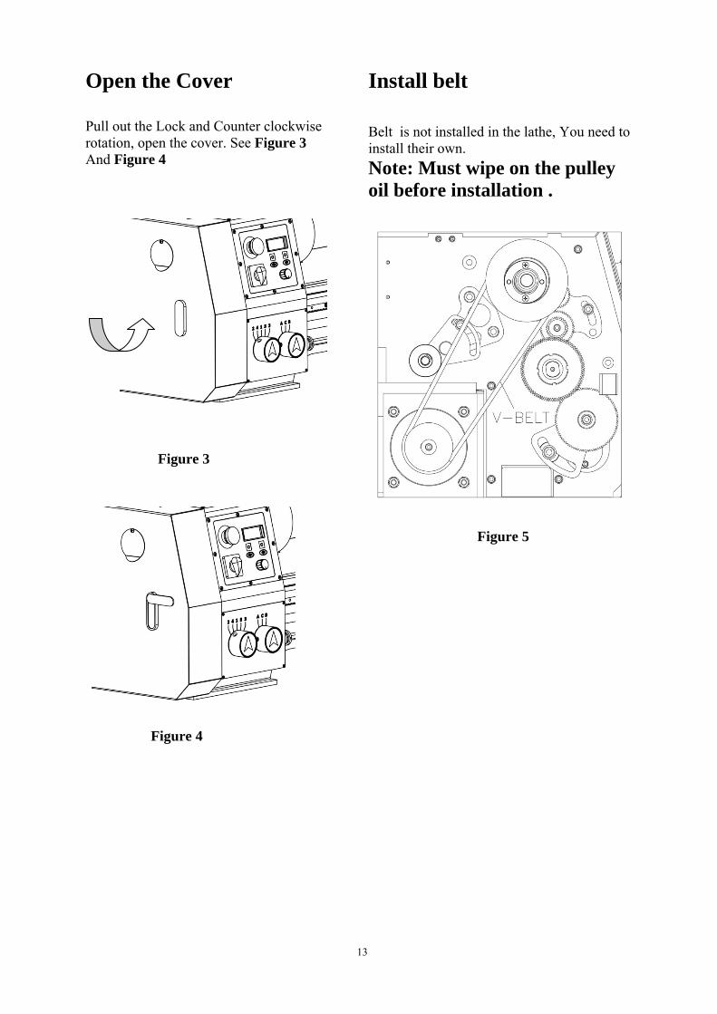
Open the Cover Pull out the Lock and Counter clockwise rotation, open the cover. See Figure 3 And Figure 4
Figure 3
Figure 4
Install belt Belt is not installed in the lathe, You need to install their own.
Note: Must wipe on the pulley oil before installation .
Figure 5

14
Test Run Lathe Before continuing to Operate, test run the lathe to make sure it runs properly. To test run the lathe, do these steps: 1. Put on safety glasses! 2. Make sure the chuck key is NOT inserted in the chuck, and that the lathe chuck guard is in the down position. Make this step a habit that you perform every time you start the lathe.
3. Familiarize yourself with the lathe controls shown in Figure 6.Make sure the STOP button is all the way down before continuing. 4. Clear all tools, components, packing material, etc. away from the cutter head. 5. Plug the machine into the power outlet! 6. Move the carriage feed lever up to the disengage mode. 7. Press the “Start”. The “Speed Displaying” should light up. 8. Flip up the emergency stop button to reveal the red , turn the lathe ON. 9. Stand to the side of the chuck, press the “Forward”. If the carriage starts moving, immediately push the STOP button and disengage the carriage feed lever, then restart the lathe. 10. Allow the lathe to run for at least two full minutes to make sure it is running satisfactorily and the chuck is turning clockw 11. Press the “Stop”. 12. After the chuck has come to a complete stop, Press the “Forward”.
Figure 6: Main lathe control for test run 13. Allow the lathe to run for at least two full minutes to make sure it is running satisfactorily and the chuck is turning counter clockwise. 14. Press the “Stop”. 15. After the lathe has come to a complete stop, engage the carriage handwheel, rotate the handwheel to center the carriage on the bed, then disengage the handwheel. 16. Engage the automatic carriage feed lever. 17. Turn the lathe ON. 18. Verify that the carriage moves along the bed, then press the emergency stop button to turn the lathe OFF. 19. Disengage the feed lever.
Emergency Stop Switch
Drill or lathe Switch
Forward
Reverse
Stop -
Potentiometer Speed Adjust
Start
Speed Displaying

15
SECTION 4: OPERATE
General This Model will perform many types of operations that are beyond the scope of this manual. Many of these operations can be dangerous or deadly if performed incurrectly. The instructions in this section are written with the understanding that the operator has the necessary knowledge and skills to operate this machine. If at any time you are experiencing difficulties performing any operation, stop using the machine! If you are an inexperienced operator, we strongly recommend that you read books, trade articles, or seek training from an experienced lathe operator before performing any unfamiliar operations. Above all, your safety should come first!
Controls To get the most out of your machine, please take the time to familiarize yourself with the various controls and components shown in the Figures 6. Note: The "Milling/Drilling" option at the selector switch is intended for the optional installation of a milling attachment which is sold separately. Please contact your authorized dealer for more information.
Figure 7 Compound Slide
16
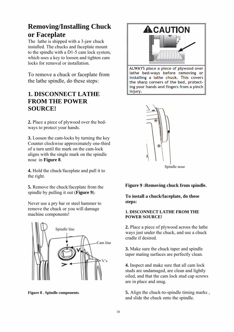
Removing/Installing Chuck or Faceplate The lathe is shipped with a 3-jaw chuck installed. The chucks and faceplate mount to the spindle with a D1-5 cam lock system, which uses a key to loosen and tighten cam locks for removal or installation. To remove a chuck or faceplate from the lathe spindle, do these steps: 1. DISCONNECT LATHE FROM THE POWER SOURCE! 2. Place a piece of plywood over the bed-ways to protect your hands. 3. Loosen the cam-locks by turning the key Counter clockwise approximately one-third of a turn until the mark on the cam-lock aligns with the single mark on the spindle nose in Figure 8. 4. Hold the chuck/faceplate and pull it to the right. 5. Remove the chuck/faceplate from the spindle by pulling it out (Figure 9). Never use a pry bar or steel hammer to remove the chuck or you will damage machine components! Spindle line
Cam line
V’s
Figure 8 . Spindle components.
Spindle nose Figure 9 :Removing chuck from spindle. To install a chuck/faceplate, do these steps: 1. DISCONNECT LATHE FROM THE POWER SOURCE! 2. Place a piece of plywood across the lathe ways just under the chuck, and use a chuck cradle if desired. 3. Make sure the chuck taper and spindle taper mating surfaces are perfectly clean. 4. Inspect and make sure that all cam lock studs are undamaged, are clean and lightly oiled, and that the cam lock stud cap screws are in place and snug. 5. Align the chuck-to-spindle timing marks , and slide the chuck onto the spindle.

17
6. Turn a cam lock with the chuck wrench until the cam mark falls between the "V" marks as shown in Figure 9A. Figure 9A. locking chuck — If the cam lock mark stops outside of the “V” marks, remove the chuck and adjust the cam stud height of the offending studs one full turn up or down (see Figure 9B)
Cam lock Stud Cap Screw Must Slightly Installed & Tight Rotate Back/Forth Figure 9B. locking chuck Initial Adjustment:
Cam lock Stud Alignment Groove is Flush with Chuck Surface
Dead Centers To install the tailstock dead center, do these steps: 1. Familiarize yourself with the tailstock components shown in Figure 10. 2. Make sure the dead center and tailstock quill are clean and free of any dirt, dust, grease, or oil. Morse tapers will not interlock when dirt or oil are present on the mounting surfaces.
3. Extend the quill approximately 1". 4. Slide the dead center into the tailstock quill as Shown in Figure 11 . Figure 10. Tailstock components. Figure 11 .Inserting dead center into tailstock quill. To remove the tailstock dead center, do these steps: 1. Use the tailstock handwheel to move the tailstock quill all the way back into the tailstock until the handwheel will no longer turn (this will push the dead center out of the quill). 2. Pull the dead center out of the tailstock quill.
18
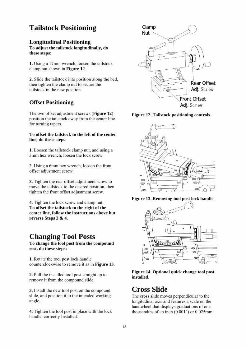
Tailstock Positioning Longitudinal Positioning To adjust the tailstock longitudinally, do these steps: 1. Using a 17mm wrench, loosen the tailstock clamp nut shown in Figure 12. 2. Slide the tailstock into position along the bed, then tighten the clamp nut to secure the tailstock in the new position.
Offset Positioning The two offset adjustment screws (Figure 12) position the tailstock away from the center line for turning tapers. To offset the tailstock to the left of the center line, do these steps: 1. Loosen the tailstock clamp nut, and using a 3mm hex wrench, loosen the lock screw. 2. Using a 6mm hex wrench, loosen the front offset adjustment screw. 3. Tighten the rear offset adjustment screw to move the tailstock to the desired position, then tighten the front offset adjustment screw. 4. Tighten the lock screw and clamp nut. To offset the tailstock to the right of the center line, follow the instructions above but reverse Steps 3 & 4.
Changing Tool Posts To change the tool post from the compound rest, do these steps: 1. Rotate the tool post lock handle counterclockwise to remove it as in Figure 13. 2. Pull the installed tool post straight up to remove it from the compound slide. 3. Install the new tool post on the compound slide, and position it to the intended working angle. 4. Tighten the tool post in place with the lock handle. correctly Installed.
Figure 12 .Tailstock positioning controls. Figure 13 .Removing tool post lock handle. Figure 14 .Optional quick change tool post installed.
Cross Slide The cross slide moves perpendicular to the longitudinal axis and features a scale on the handwheel that displays graduations of one thousandths of an inch (0.001") or 0.025mm.

19
To adjust the cross slide, do these steps: 1. Using the handwheel, back the cross slide away from your starting point by at least 0.015", then move the cross slide forward to your starting point. Note: This procedure will clear any free movement (or backlash) in the lead screw so your handwheel scale reading will be accurate. 2. Hold the handwheel still and turn the scale so the “0” mark lines up with the “0.000” mark on the cross slide, as shown in Figure 15. As long as you avoid backlash by continuing to move the cross slide in the same direction, the scale on the handwheel will be accurate. 3. After backing the cross slide away from the workpiece, remember to clear the backlash before moving the cross slide forward to the “0” mark for the next cut.
Compound Slide Similar to the cross slide, the compound slide features a scale that displays graduations of one thousandths of an inch (0.001") or 0.025mm. Unlike the cross slide, the compound slide can be rotated to a set angle and then it can be moved back and forth along the axis of that angle. To adjust the compound slide, do these steps: 1. Loosen the compound bolts shown in Figure 13 to allow it to be rotated. 2. Rotate the compound slide to the angle needed for your procedure. 3. Tighten the compound slide bolts, and check the angle again to make sure it did not move during tightening. 4. Use the compound slide handwheel to move the tool back and forth along the axis of the new angle. Similar to adjusting the cross slide handwheel, make sure the threads are engaging and all backlash has been cleared before you set the handwheel scale to “0”, or it will not be accurate.
Figure 15 .Adjusting graducated dial.
Figure 16 .Loosening the compound slide bolts and compound Cap screws. 4. Loosen the compound Cap screws shown in Figure 16 to allow it to be transversal traveled .
Carr
The carrcarriage control imachineis desire
Half The halfthe leverFigure 1operation
left When thscrew is The leve
Carr Longitudare contrThe leverequire m18).
Carr The carrfront righ19). This boltincreased
riage Ha
riage handwhleft or right
is necessary we for turning d during turn
Nut Le
f nut lever car to the right 19.Use this pns.
Figure1
he lever is moselected for
er is only eng
riage/Cr
dinal and crorolled by theer pivots thromoving the le
Up
Figu
riage Lo
riage is supplht-hand side
t locks the cad rigidity wh
andwhe
heel (Figure along the bewhen settingor when manning operatio
ever
an be selectedas in Figure
position for a
right 17.
oved to the lethreading op
gaged while c
ross Fee
oss slide powe carriage/croough pulls anever up and d
Down
re 18
ock
lied with a lo of the saddl
arriage in plahen making f
eel
14)moves thed. This manug up the nual movemeons.
d by movinge 17 and all feed
eft , the lead perations. cutting threa
ed Leve
wered motionoss feed levernd rotates thadown (Figur
ock bolt on thle (see Figur
ace for face cuts. Th
20
he ual
ent
g
ads
er
ns r. at re
he re
his
lomf
F
G
Thole1a
F
Iththw6sS
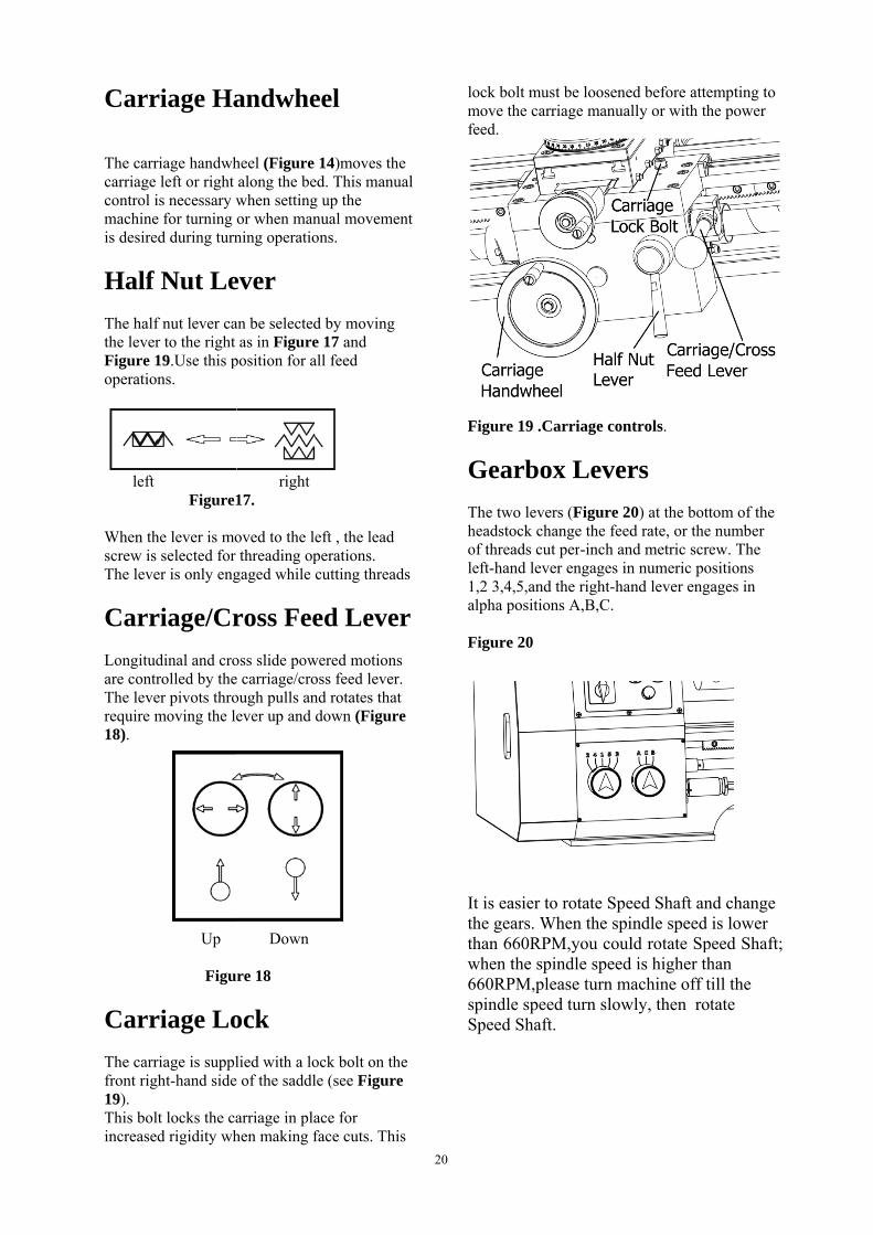
ock bolt musmove the carrfeed.
Figure 19 .C
Gearbo
The two leverheadstock chaof threads cuteft-hand leve
1,2 3,4,5,and alpha position
Figure 20
t is easier tohe gears. Whan 660RPM
when the spi660RPM,plespindle speeSpeed Shaft
st be looseneriage manual
arriage con
x Lever
rs (Figure 20ange the feedt per-inch aner engages inthe right-han
ns A,B,C.
o rotate SpeWhen the spi
M,you coulindle speedease turn maed turn slow.
ed before attelly or with th
trols.
rs
0) at the bottd rate, or the
nd metric scren numeric pond lever eng
eed Shaft anindle speed ld rotate Sp
d is higher thachine off t
wly, then rot
empting to he power
tom of the e number ew. The
ositions ages in
nd change is lower
peed Shaft; han till the tate

21
Use the feed rate chart shown in Figure 22 to position the quick change gearbox levers.
Figure 22 imperial chart .
Threads and Change gears This lathe(imperial) has 15+5 (+5 needs change gears) =20 kinds imperia screw and 6 +6 (+6 needs change gears)=12 kinds metric screw ,together . To machine these thread ,just adjust the gear box levers ,then you can save the trouble of changing the gears. Z30 gear has been installed in the machine when you receive the machine, the change gear is Z30/Z91/Z90, see Figure 23. We prepared five gear Z35 ,Z49,Z50, Z56,Z60 for imperial lathe ,to enable the imperial lathe with more metric thread .You must change the change gear to states as Figure 22, and you can get extra 6 kinds metric screw and 5 kinds imperia screw as Form 1 by changing between Z30 Z35 Z49 Z50 Z56 Z60 based on thread pitch . Use Z56 replace Z86, have screw 13 and 26 See Fig 22 and Fig 23
Please use Fwd and Rev when cutting thread. We advise you to adjust the speed to 125r/min when you make thread ,and the screw relief groove must be three times than screw pitch at least. If the screw pitch is less than 1.5mm ,the groove must be not less than 4mm.After you can operate the machine skillfully ,you can adjust the speed or the groove, so your safety can be guaranteed..

22
Figure 23 Change Gears
Left threads and reverse cutting feed
Gear A has been used in the machine when you receive the machine, It can meet the general processing. When you cut the left threads or need reverse cutting feed, must use the Gear B. Loosen the Screw 1 and adjust the Gear B to good running .

ClutcThis mac(Part #53overloadFigure 2use the a
Stoppany rStopp
ch Overchine is furn38) touch Stod protection d25 ,The Adaccessories o
ping Platequired
ping Plat
Figure
A L
Figure
rload nished with Copping plate device can addj. Nut to bedof the two roo
te can mspot.
te can m
Stop
Adj Clutch O
e 24 Clutch
AdjustmenLever
e 25 Change
Clutch Overlo, this device
djust and rotd side rotatioot Adjustmen
move alon
make Car
pping Plate
j. Nut
Overload
Overload
nt
e Gear
23
oad protectioe will work atate, The Adj
on to increasent Lever to a
ng the be
rriage re
e
on device. Wand stop the fdj. Nut can ade torque, outwadjust.
ed to pro
epeat sto
When it’s loadfeeding of thdjust the torcward to redu
otect the
p where
ded over or the cutter. Cluch of the overuce the torque
e machin
ever you
the slide utch rload. See e, please
ne at
want.

24
SECTION 6: MAINTENANCE Lubrication Your lathe has numerous moving metal-to-metal contacts that require proper lubrication to help ensure efficient and long-lasting operation. Other than the lubrication points covered in this section, all other bearings are internally lubricated and sealed at the factory. Simply leave them alone unless they need to be replaced. Before adding lubricant, clean away any debris and grime from the lubrication point to avoid contaminating the lubricant and increasing wear of the moving parts. DISCONN ECT THE LATHE FROM POWER BEFORE PERFOR MING LUBRI CATION ! Note : The change gears and the ball oilers have the same lubrication
Ball Oilers Lubricant Frequency Qty
ISO 68 or Equivalent Lubricant
Every 8 Hours of Operation
1 Squit From Oil Can
Figure 26
Figure 27 Figure 28 Figure 29

25
Feed Rate Gearbox Oil Reservoir Lubricant Frequency Qty
ISO 68 or Equivalent Lubricant
Check/ Fill Every 8 Hours of Operation
Half-Way Mark in Sight Glass
The feed rate gearbox oil reservoir must be checked and oil added, if necessary, on a daily basis. Tools Needed Qty Hex Wrench 6mm............................................ 1 To check and add oil to the reservoir: 1. Check the oil reservoir sight glass shown in Figure 30. If the oil level is below the halfway mark, continue with the following steps to add oil.
Figure 30 2. Wipe clean the area around the fill plug to
prevent debris from falling into the reservoir when adding oil.
1. Remove the fill plug.
2. S lowly add oil until the level is centered in the sight glass.
5. Replace the fill plug.
NOTICE The feed rate gearbox oil must be changed after the first three months of operation, then annually after that.
To change the oil in the reservoir: 1. DISCONN ECT LATHE FROM POWER! 2. Remove the reservoir fill plug (see Figure 30. Note: If you are experiencing difficulty removing the fill plug, do not remove the drain plug to drain the reservoir until you can successfully remove the fill plug. This way you can still operate the lathe until the issue is resolved. 3. Hold the drain pan under the reservoir drain plug, then remove the drain plug shown in Figure 30, and allow the oil to completely drain into the pan.
26
Gibs
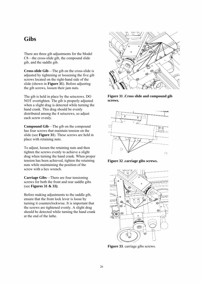
There are three gib adjustments for the Model C8—the cross-slide gib, the compound slide gib, and the saddle gib. Cross-slide Gib—The gib on the cross-slide is adjusted by tightening or loosening the five gib screws located on the right-hand side of the slide (shown in Figure 31). Before adjusting the gib screws, loosen their jam nuts. The gib is held in place by the setscrews. DO NOT overtighten. The gib is properly adjusted when a slight drag is detected while turning the hand crank. This drag should be evenly distributed among the 4 setscrews, so adjust each screw evenly. Compound Gib—The gib on the compound has four screws that maintain tension on the slide (see Figure 31). These screws are held in place with retaining nuts. To adjust, loosen the retaining nuts and then tighten the screws evenly to achieve a slight drag when turning the hand crank. When proper tension has been achieved, tighten the retaining nuts while maintaining the position of the screw with a hex wrench. Carriage Gibs—There are four tensioning screws for both the front and rear saddle gibs (see Figures 31 & 33). Before making adjustments to the saddle gib, ensure that the front lock lever is loose by turning it counterclockwise. It is important that the screws are tightened evenly. A slight drag should be detected while turning the hand crank at the end of the lathe.
Figure 31 .Cross slide and compound gib screws.
Figure 32 .carriage gibs screws. Figure 33. carriage gibs screws.

27
Bearing Preload This lathe is shipped from the factory with the spindle bearing preload properly adjusted. If the spindle ever develops excessive end-play and the workpiece finish suffers, you can adjust the bearing preload to remove the unnecessary end-play and improve the workpiece finish. To adjust the spindle bearing preload: 1. Run the lathe for approximately 20 minutes on high speed to bring the lathe to normal operating temperature. 3. DISCONNECT LATHE FROM
POWER!
4. Remove the Screw (see Figure 34)
Figure 34 5. Loosen the Spindle Lock Nut one full
turn counterclockwise. (see Figure 35) The wrench of spindle 3-jaw chuck key
Spindle lock nut
Figure 35
6. Place a wooden block over the outboard end of the spindle, and hit it soundly with the heavy dead blow hammer (see Figure 36). Your goal is to slide the spindle forward just enough to introduce spindle end-play that you can feel by hand.
Figure 36 1. Clockwise to tighten the Spindle Lock
Nut, Rotating the 3-Jaw Chuck with spindle, Check the spindle bearing preload, Spindle should be no gap, rotating with slight resistance. The need to repeatedly to loosen or tighten the Spindle Lock Nut adjustment.
To confirm that the spindle bearings are correctly preloaded: 1. Reattach all removed lathe components and prepare it for operation. 2. Install the chuck and tighten the jaws into the center. 3. Set the spindle speed to a medium setting. 4. Connect the lathe to power and turn the lathe spindle ON. 5. Let the lathe run for 20 minutes.

28
6. Turn the spindle OFF, disconnect the lathe from power, then check the temperature of the spindle. — If the spindle nose is slightly warm to the touch, you have correct bearing preload. — If the spindle nose is hotter than you can comfortably keep your hand on, the preload is too tight and you must repeat the bearing preload adjustment procedure. When repeating the procedure, rotate the inner spanner nut a little less during Step 7 in the preceding instructions.
NOTICE
Do not over tighten the outer spanner nut because additional pressure can force the bearings even tighter against the races in the headstock and cause the headstock to compress, crack, or cause bearing failure.
29

30
PARTS LIST
No. Code Description No. Code Description
101 C82300 Protective shield 116 GB/T 70.1 M8 x 45 Screw M8 x 45
102 GB/T 70.1 M8 x 12 Screw M8 x 12 117 GB/T 6173 M10 Nut M10
103 GB/T 97.1 8 Flat washer 118 GB/T 1046 A 4 x 4 x 28 Flat key
104 C80107 Bed 119 GB/T 70.2 M6 x 16 Screw M6 x 16
106 C80108A Lead screw 120 GB/T 119.1 6 h8 x 16 Round pin
107 GB/T 6173 M12 Nut M12 121 C80110 Rack
108 GB/T 97.1 12 Fat washer 122 GB/T 97.1 6 Flat washer
109 C80102 Lead screw support 123 GB/T 70.1 M6 x 12 Screw M6 x 12
110 C80103 Protective support 124 GB/T 848 6 Flat washer
111 GB/T 70.1 M4 x 8 Screw M4 x 8 125 GB/T 6170 M6 Nut M6
112 C80109 Polish rod 126 GB 93-87 8 Spring washer
113 GB/T 97.1 10 Flat washer 127 GB/T 848 10 Flat washer
114 GB/T 119.1 5 h8 x 30 Round pin 128 GB/T 848 12 Flat washer
115 JB/T7940.4 Φ6 Oil cup

31

32
No. Code Description No. Code Description
201 C80214 Spindle box cover 284 C80202A Spindle gear
202 GB/T 70.1 M5 x 12 Screw M5 x 12 285 C80203A Spindle space ring
222 GB 862.1-87 4 Lock washer 286 C80225A End oil circle
223 GB/T 97.1 4 Flat washer 287 6010-2Z GB/T 276-94
Bearing
224 GB 93-87 4 Spring washer 288 GB 893.1-86 - 80 External circlip
225 Gnd φ4 Earth lag φ4 289 C80210A Middle oil circle
226 GB/T 818 M4 x 12 Screw M4 x 12 290 32011 GB/T 297-94 Conical roller bearing
227 C80212 Blackout axis 291 C80209A Front oil circle
228 GB 894.1-86 - 8 External circlip 292 GB/T 1096 - A 6 x 6 x 12
Key
230 QKS7 Switch 293 GB/T 1096 - A 6 x 6 x 8
Key
231 GB/T 70.1 M4 x 20 Screw M4 x 20 294 C80205A Spindle
232 GB/T 97.1 4 Flat washer 295 C80231 Cam
234 GB/T 97.1 4 Flat washer 296 C80228 Rigister pin
235 GB/T 6170 M4 Nut M4 297 C80229 Spring
236A C80201A Spindle box 298 GB 93-87 8 Spring washer
237 GB/T 70.3 M5 x 12 Screw M5 x 12 299 GB/T 70.1 M8 x 14 Screw M8 x 14
241 GB/T 819.1 M4 x 12
Screw M4 x 12 2001 C80251 Plate A
242 ZH-HC-2 change-over switch 2002 GB818 M3 x 12 Screw M3 x 12
243 S4-12 Blinding post 2003 ZM3326 Holzer
244 GB/T 70.1 M4 x 30 Screw M4 x 30 2004 SC8020105 Plastic washer
245 GB/T 70.1 M10 x 35
Screw M10 x 35 2005 C80252 Plate B
246 GB/T 819.1 M4 x 12
Screw M4 x 12 2006 GB70.1 M4 x 10 Screw M4 x 10
251 GB/T 70.2 M5 x 12 Screw M5 x 12 2007 C80221B Double speed pulley
265 GB/T 818 M2.5 x 14
Screw M2.5 x 14 2102 C80255 Block
266 GB/T 6170 M3 Nut M3 2103 GB/T 70.1 M6 x 12 Screw M6 x 12
268 SC8020105 Plastic ring 2104 GB/T 97.1 6 Washer 6
269 SC8020101 Switch panel 2106 GB/T 97.1 8 Washer 8
270 SC8020103 Compression spring 2107 C60221 Lock plate
271 GB/T 819.1 M3 x 20
Screw M3 x 20 2108 C60220 Regulating rod
272 HY57B Emergency switch 2109 GB/T 6170 M8 Nut M8
273A SC8020102 A Control panel stick 2151 QKS20320 Switch
275 C80230 Levers 2152 GB 818 M4 x 30 Screw M4 x 30
276 GB/T 70.1 M6x 10 Screw M6x 10 2153 SB-10 Plastic sleeve
277 K11 160/D4 Three jaw chuck 2160 A-4A Control Panel board
281 C80211A Spindle locknut 2169 Φ30 Knob
283 C80204A Spindle spacer bush 2170 WH24-1 Potentiometer
33
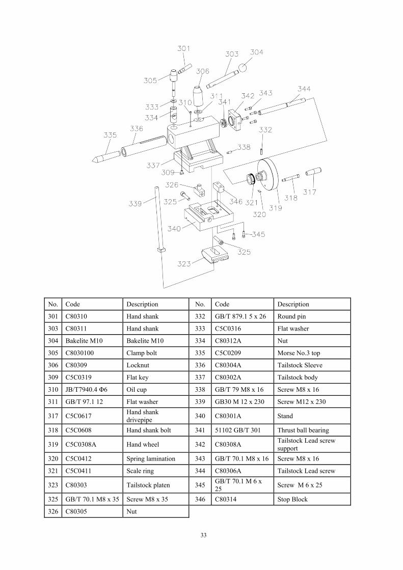
No. Code Description No. Code Description
301 C80310 Hand shank 332 GB/T 879.1 5 x 26 Round pin
303 C80311 Hand shank 333 C5C0316 Flat washer
304 Bakelite M10 Bakelite M10 334 C80312A Nut
305 C8030100 Clamp bolt 335 C5C0209 Morse No.3 top
306 C80309 Locknut 336 C80304A Tailstock Sleeve
309 C5C0319 Flat key 337 C80302A Tailstock body
310 JB/T7940.4 Φ6 Oil cup 338 GB/T 79 M8 x 16 Screw M8 x 16
311 GB/T 97.1 12 Flat washer 339 GB30 M 12 x 230 Screw M12 x 230
317 C5C0617 Hand shank drivepipe
340 C80301A Stand
318 C5C0608 Hand shank bolt 341 51102 GB/T 301 Thrust ball bearing
319 C5C0308A Hand wheel 342 C80308A Tailstock Lead screw support
320 C5C0412 Spring lamination 343 GB/T 70.1 M8 x 16 Screw M8 x 16
321 C5C0411 Scale ring 344 C80306A Tailstock Lead screw
323 C80303 Tailstock platen 345GB/T 70.1 M 6 x 25
Screw M 6 x 25
325 GB/T 70.1 M8 x 35 Screw M8 x 35 346 C80314 Stop Block
326 C80305 Nut
34
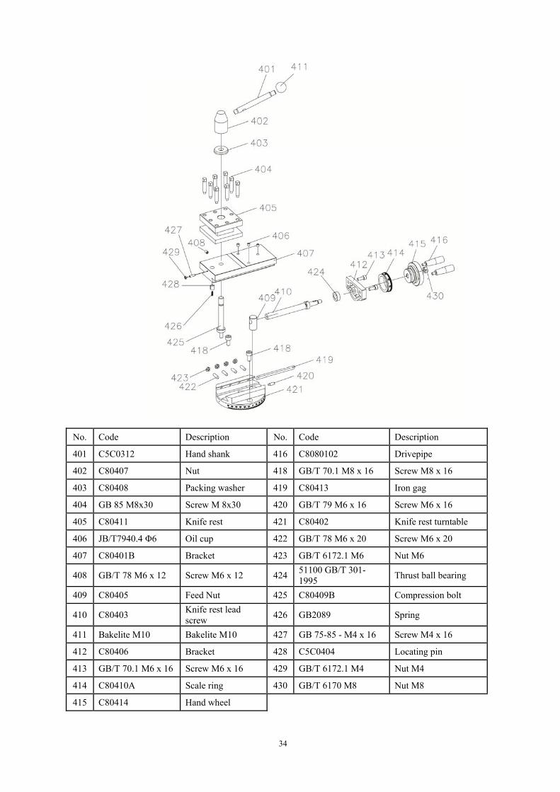
No. Code Description No. Code Description
401 C5C0312 Hand shank 416 C8080102 Drivepipe
402 C80407 Nut 418 GB/T 70.1 M8 x 16 Screw M8 x 16
403 C80408 Packing washer 419 C80413 Iron gag
404 GB 85 M8x30 Screw M 8x30 420 GB/T 79 M6 x 16 Screw M6 x 16
405 C80411 Knife rest 421 C80402 Knife rest turntable
406 JB/T7940.4 Φ6 Oil cup 422 GB/T 78 M6 x 20 Screw M6 x 20
407 C80401B Bracket 423 GB/T 6172.1 M6 Nut M6
408 GB/T 78 M6 x 12 Screw M6 x 12 42451100 GB/T 301-1995
Thrust ball bearing
409 C80405 Feed Nut 425 C80409B Compression bolt
410 C80403 Knife rest lead screw
426 GB2089 Spring
411 Bakelite M10 Bakelite M10 427 GB 75-85 - M4 x 16 Screw M4 x 16
412 C80406 Bracket 428 C5C0404 Locating pin
413 GB/T 70.1 M6 x 16 Screw M6 x 16 429 GB/T 6172.1 M4 Nut M4
414 C80410A Scale ring 430 GB/T 6170 M8 Nut M8
415 C80414 Hand wheel
35

36
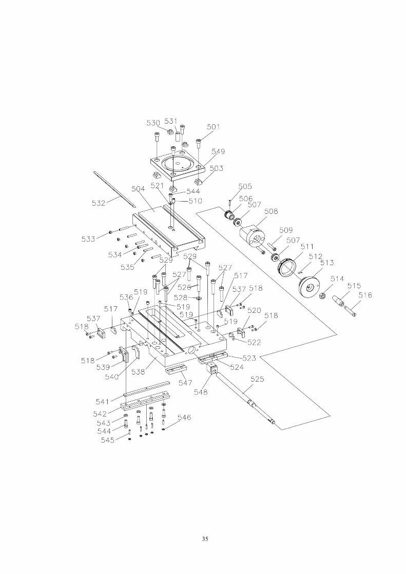
No. Code Description No. Code Description
501 GB/T 70.1 M8 x 20 Screw M8 x 20 526 GB/T 70.1 M8 x 45 Screw M8 x 45
503 C80505 T nut 527 GB/T 70.1 M8 x 40 Screw M8 x 40
504 C80502 Work table 528 GB/T 97.1 8 Flat washer
505 GB/T 879.1 3 x 18 Round pin 529 GB/T 70.1 M8 x 35 Screw M8 x 35
506 C80520 Gear 22T 530 C80504 T nut
507 51100 GB/T 301 Thrust ball bearing 531 C80510A Knife rest dial axis
508 C80516A Lead screw support 532 C80521 Iron gag
509 GB/T 70.1 M6 x 35 Screw M6 x 35 533 GB/T 6170 M5 Nut M5
510 GB/T 78 M8 x 16 Screw M8 x 16 534 C80525 Screw
511 C80517 Scale ring 535 GB/T 78 M5 x 30 Screw M5 x 30
512 C5C0412 Spring lamination 536 GB/T 77 M8 x 8 Screw M8 x 8
513 C80518 Hand wheel 537 C80515 Preventer plate
514 GB/T 6170 M10 Nut M10 538 C80501 Saddle
515 C5C0617 Hand shank drivepipe
539 C80513 Preventer plate
516 C5C0608 Hand shank bolt 540 C80522 Felt
517 C80524 Felt 541 C80526 Iron gag
518 GB/T 818 M4 x 12 Screw M4 x 12 542 C80508 Platen
519 JB/T7940.4 Oil cup 543 GB/T 97.1 6 Flat washer
520 C80514 Preventer plate 544 GB/T 70.1 M6 x 20 Screw M6 x 20
521 GB/T 848 6 Flat washer 545 GB/T 75 M4 x 16 Screw M4 x 16
522 C80523 Felt 546 GB/T 6172 M4 Nut M4
523 C80507 Platen 547 C80506 Platen
524 C80509 Platen 548 C80511 Feed screw nut
525 C80519 Saddle lead screw 549 C80503A Knife rest turntable seat
37

38
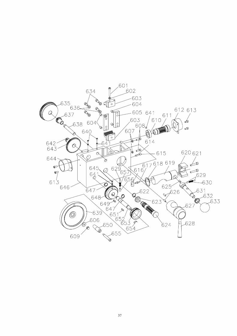
No. Code Description No. Code Description
601 GB/T 70.1 M5 x 35 Screw M5 x 35 630 C80611 Pressure spring
602 GB/T 6172.1 M6 Nut M6 631 C80607 Control shaft
603 C80605A Nut 632 C80610 Pressure spring
604 GB/T 77 M8 x 10 Screw M8 x 10 633 C80624 Bakelite handle
605 C80606 Platen 634 GB/T 70.1 M6 x 16 Screw M6 x 16
606 GB/T 96.1 6 Flat washer 635 C80614A Gear 81T
607 GB/T 6170 M5 Nut M5 636 GB/T 97.1 6 Flat washer
608 GB/T 70.1 M5 x 16 Screw M5 x 16 637 C80618 Gear 22T
609 GB 923 M6 Nut M6 638 C80617 Ⅲ axis
610 C80616 Nut 639 X3111900 Hand shank
611 C80615 I axis 640 GB/T 77 M6 x 6 Screw M6 x 6
612 C80626 Support 641 GB/T 78 M6 x 6 Screw M6 x 6
613 GB/T 70.1 M5 x 10 Screw M5 x 10 642 C80620 Ⅳ axis
614 GB/T 79 M6 x 12 Screw M6 x 12 643 C80619 Gear 67T
615 GB/T 77 M6 x 8 Screw M6 x 8 644 C80629 Support
616 C80609A Slider 645 GB/T 78 M6 x 8 Screw M6 x 8
617 C80604A Round pin 646 C80601 Slide carriage
618 GB 894.1-86 - 35 External circlip 647 GB 894.1-86 - 14 External circlip
619 C80603 Control shaft 648 C80621 Gear 60T
620 C80608 Briquetting 649GB/T 1096 - A 5 x 5 x 16
Key
621 GB/T 70.1 M6 x 30 Screw M6 x 30 650 C80631 Hand shank drivepipe
622 GB 894.1-86 - 15 External circlip 651GB/T 1096 - A 4 x 4 x 16
Key
623 C80623 Spacer bush 652 C80622 Ⅴ axis
624 C80613 Ⅱ axis 653 C80625 Scale ring
625 GB/T 119.1 5 h8 x 12 Round pin 654 C5C0412 Spring lamination
626 GB/T 119.1 6 h8 x 18 Round pin 655 C80630 Hand shank bolt
627 C80602 Camshaft 656 GB/T 77 M8 x 12 Screw M6 x 12
628 C5C0312 Hand shank 657 C80612 Pressure spring
629 Steel ball Φ6 Steel ball

39
No. Code Description No. Code Description
701 GB/T 70.1 M5 x 12 Screw M5 x 12 738 C8070101/02/03 Gear Z13/z40
702 GB9877.1 22 x 35 x 7 Oil seal 739HE- 12.5 x 1.8-G-GB/T 3452.1
Seal ring
703 C80708 End cap 740 C8070104 Axis
704 C8070506 Nameplate 741 GB/T 78 M5 x 8 Screw M5 x 8
705 GB/T 1096 - A 4 x 4 x 16 Key 742Oil displaying M16 x 1.5
Oil pointer
706 C80712 Ⅱ axis 743 C80709 End cap
707 GB/T 1096 - A 5 x 5 x 80 Key 744 C80719 I axis small bush
708 C80715 Ⅱ axis spacer bush
745 C8070400A Gear
709 C80725A Gear Z36 746 C80713 I axis
710 C80722A Gear Z24 747 Steel ball Φ5 Steel ball

40
No. Code Description No. Code Description
711 C80721 Ⅱ axis spacer bush
748 C80724A Gear Z19/38/28
712 C80723A Gear Z24 749 C8070201 Gear Z42
714 C80706A Gear Z24 750 C80720 I axis big bush
715 C80705A Gear Z34 751 SOG 25 x 32 x 4 Oil seal
716 GB 894.1-86 - 16 External circlip 752 C80711 End cap
717 C80707 Gearbox casing 753 C8070504 Hand wheel
718 GB/T 1096 - A 5 x 5 x 12 Key 754 C8070202 Hollow cover
719 C80718 Cover 755HE- 15 x 1.8-G-GB/T 3452.1
Seal ring
720 C80714 Ⅲ axis 756 C8070203 Connecting shaft
721 GB/T 1096 - A 4 x 4 x 60 Key 757 C8070204 Driven shaft
722 C80701A Gear Z28 758 C8070205 Adjust cover
723 C80717 Ⅲ axis spacer bush
759 C8070206 Compression spring
724 C80702 Gear Z19 760 C8070207 Screw
725 C8070502 Pin 761HE- 8.75 x 1.8-G-GB/T 3452.1
Seal ring
726 C80703 A Gear Z38 762 GB/T 78 M6 x 12 Screw M6 x 12
727 C80704 Gear Z14 763 C8070503 Pin
728 HE- 30 x 2.65-G-GB/T 3452.1
Seal ring 764 GB/T 70.1 M8 x 80 Screw M8 x 80
729 C80710 End cap 765GB/T 1096 - A 5 x 5 x 50
Key
730 GB 894.1-86 - 10 External circlip 766GB/T 1096 - A 5 x 5 x 32
Key
731 GB9877.1 18 x 30 x 7 Oil seal 767 GB/T 879.1 4 x 24 Round pin
732 C80103 Support 768 GB/T 819.1 M3 x 6 Screw M3 x 6
733 GB/T 70.1 M4 x 8 Screw M4 x 8 769 C8070501 Driving lever
734 C80716 Ⅲ axis connect cover
770 GB/T 879.1 4 x 18 Round pin
735 Oil screw M16 x 1.5 Oil plug 771 C8070505 Gearbox cover
736 AE- 16 x 2.65-G-GB/T 3452.1
Seal ring 772 GB/T 70.1 M5 x 30 Screw M5 x 30
737 GB2089 0.7 x 4 x 25 Compression spring
773 C8070507 Nameplate

41
No. Code Description No. Code Description
801 GB/T 818 M4 x 10 Screw M4 x 10 830 GB 810 M30 x 1.5 Nut M30 x 1.5
802 GB/T 97.1 4 Flat washer 831 C8080202 Gear Z86
803 GB/T 6170.1 M4 Nut M4 832 C8080201 Gear Z91
804 3" Hingle 3" Hingle 833 C8080205 Shaft sleeve
806 M8 x 1 Sprayer M8 x 1 Sprayer 834 C8080204 Washer
807 C8080107 Axis 835 C8080203 Nut
808 C8080105 Bush 836 JB/T7940.4 φ6 Oil cup
810 C8080106 Washer 845 GB/T 97.1 6 Flat washer
811 GB/T 70.1 M8 x 25 Screw M8 x 25 846 C8080102 Hand shank
812 GB/T 97.1 8 Flat washer 847 C8080206 Washer
813 GB/T 78 M5 x 16 Screw M5 x 16 848 C8080207 Spacer bush
816 GB/T 818 M5 x 12 Screw M5 x 12 849 C8080209 Gear Z90
817 C5C1504 Shield 850 GB/T 70.1 M10 x 45
Screw M10 x 45
818 GB/T 70.1 M6 x 14 Screw M6 x 14 851 GB/T 70.1 M6 x 12 Screw M6 x 12
819 C8080108 Washer 853 C8080208 Washer
820 GB/T 1096 - A 4 x 4 x 22
Key 854 C8080101A Hanging round body
821 C8080109 Gear Z30 855 C8080103A Gear Z65
823 C8080110 Spacer bush 856 C8080104A Gear Z48
824 C8080111 Liner pipe 857 C8080210A Hanging round body
825 C8080112 Fixed axis 858 C8080300A Door plank
826 GB/T 6170.1 M6 Nut M6 859 C8080400A Cover
827 C8080405 Hand shank 860 MS00 Lock
828 C8080211 Transition axis 862 Qks20320 key Switch key
829 GB/T 1096 - A 8 x 7 x 14
Key

42

43
901 Power line Power line 955 C80911 Shaft
902 M12 M12 959 GB/T 6170 M8 Nut M8
905 NB1-63-32 Breaker 32A 960 GB 93-87 8 Spring washer
906 GB/T 819.1 M4 x 8 Screw M4 x 8 961 GB/T 70.1 M8 x 25
Screw M8 x 25
907 C80906 Spile 962 GB/T 70.1 M8 x 40
Screw M8 x 40
914 GB/T 70.1 M5 x 12 Screw M5 x 12 963 GB/T 5287 6 Flat washer 6
915 C80214 Spindle box cover 965 GB/T 1096 - A 6 x 6 x 22
Key
916 GB/T 819.1 M3 x 10
Screw M3 x 10 966 C80903 Connecting Board
917 SS-8B Outlet 967 W122-1500C 1500W motor
918 GB/T 6170 M3 Nut M3 968 C80910 Wheel holder
921 GB/T 70.1 M8 x 25 Screw M8 x 25 970 O-838 Triangle belt
922 GB/T 97.1 8 Fat washer 9001 C80908B Motor pulley
923 C5C1518 Support 9105 GB/T 818 M4 x 8 Screw M4 x 8
924 C61511 Washer 9106 C8090210 Lower cover
925 GB/T 70.1 M10 x 40
Screw M10 x 40 9112 GB/T 97.1 4 Flat washer 4
927 C8090102 Washer 9115 0902C0100 Motor shield
936 C61512 Pivot 9116 GB/T 70.1 M6 x 12
Screw M6 x 12
937 C61513 Washer 9126 C8090212 Electric box
938 GB/T 97.1 10 Fat washer 9127A C8090219B Electric plate
939 GB/T 6170 M10 Nut M10 9128 GB/T 819.1 M4 x 12
Screw M4 x 12
944 GB/T 96.1 8 Fat washer 9129 GB/T 818 M4 x 60
Screw M4 x 60
947 GB/T 70.1 M6 x 16 Screw M6 x 16 9132 Z-1500-6A PC Board
951 GB 893.1-86 - 37 External circlip 9133 C8090213 PC mounting plate
952 C80909 Wheel 9134 C80930 ABS washer
953 GB 894.1-86 - 12 External circlip 9135 Φ12 Rubber ring
954 6301-GB/T 276-94 Bearing