instruction manual - american fibertek - home series switches... · instruction manual. 18-may-11...
TRANSCRIPT
SM8P-SFP
6-Port 100/1000 SFP with
2 RJ-45/100/1000 SFP Combo Port
Managed Switch
Instruction Manual

18-May-11
Regulatory Approval- FCC Class A- UL 1950- CSA C22.2 No. 950- EN60950- CE- EN55022 Class A- EN55024
Canadian EMI NoticeThis Class A digital apparatus meets all the requirements of the Canadian Interference-Causing EquipmentRegulations.
Cet appareil numerique de la classe A respecte toutes les exigences du Reglement sur le materiel brouilleurdu Canada.
EuropeanNoticeProducts with the CE Marking comply with both the EMC Directive (89/336/EEC) and the Low VoltageDirective (73/23/EEC) issued by the Commission of the European Community Compliance with thesedirectives imply conformity to the following European Norms:
EN55022 (CISPR 22) - Radio Frequency InterferenceEN61000-X - Electromagnetic ImmunityEN60950 (IEC950) - Product Safety

18-May-11
Table of Contents
1.0 INTRODUCTION........................................................................................................................ 2
1-1. Overview of Sm8p-Sfp..............................................................................................................................21-2. Checklist ...........................................................................................................................................61-3. Features......................................................................................................................................................61-4. Full View of Sm8p-Sfp .............................................................................................................................8
1-4-1.UserInterfacesontheFrontPanel(Button,LedsandPlugs)......................................................... 81-4-2.AcPower Inputon theRearPanel ..............................................................................................9
1-5. View of the Optional Modules .........................................................................................................10
2.0 INSTALLATION................................................................................................................................11
2-1. Starting SM8P-SFP Up...................................................................................................................112-1-1. Hardware and Cable Installation...........................................................................................112-1-2. Installing Chassis to a 19-Inch Wiring Closet Rail ...............................................................132-1-3. Cabling Requirements ..........................................................................................................13
2-1-3-1. Cabling Requirements for TP Ports...............................................................................132-1-3-2. Cabling Requirements for 100/1000M SX/LX SFP Module.........................................132-1-3-3. Switch Cascading in Topology .....................................................................................14
2-1-4. Configuring the Management Agent of SM8P-SFP..............................................................172-1-4-1. Configuring the Management Agent of SM8P-SFP through the Console RJ-45 Port ...172-1-4-2. Configuring the Management Agent of SM8P-SFP through the Ethernet Port .............19
2-1-5. IP Address Assignment.........................................................................................................202-2. Typical Applications.......................................................................................................................24
3.0 OPERATION OF WEB-BASED MANAGEMENT................................................................. 26
3-1. Web Management Home Overview.......................................................................................................283-1-1.System Information................................................................................................................313-1-2.AccountConfiguration ...........................................................................................................333-1-3.TimeConfiguration ................................................................................................................343-1-4. IP Configuration.....................................................................................................................373-1-5. Loop Detection ......................................................................................................................403-1-6.Management Policy................................................................................................................413-1-7. Syslog....................................................................................................................................443-1-8. System Log............................................................................................................................453-1-9.Virtual Stack ..................................................................................................................................46
3-2. Port Configuration ...................................................................................................................................483-2-1.PortConfiguration..................................................................................................................483-2-2.Port Status ......................................................................................................................................503-2-3.SimpleCounter ......................................................................................................................533-2-4.DetailCounter........................................................................................................................553-2-5.Power Saving .........................................................................................................................58
3-3. VLAN .............................................................................................................................................593-3-1.VLAN Mode..........................................................................................................................593-3-2.Tag-based Group ...........................................................................................................................603-3-3.Port-based Group ..........................................................................................................................633-3-4. Ports ......................................................................................................................................653-3-5.Port Isolation..........................................................................................................................673-3-6.ManagementVLAN...............................................................................................................68
3-4. MAC ...............................................................................................................................................69

Rev.A118-May-11
iv
3-4-1.Mac AddressTable..........................................................................................................................................693-4-2. Static Filter .....................................................................................................................................713-4-3. Static Forward.........................................................................................................................................723-4-4.MAC Alias .....................................................................................................................................733-4-5.MAC Table.......................................................................................................................................................74
3-5.GVRP ......................................................................................................................................................753-5-1. Config............................................................................................................................................753-5-2. Counter ..........................................................................................................................................783-5-3. Group......................................................................................................................................................80
3-6.QOS(QUALITY OF SERVICE)CONFIGURATION ....................................................................................813-6-1. Ports...............................................................................................................................................813-6-2.Qos ControlList.............................................................................................................................. 833-6-3.Rate Limiters ..................................................................................................................................883-6-4.Storm Control ..........................................................................................................................................893-6-5.Wizard .....................................................................................................................................................90
3-7.SNMPCONFIGURATION............................................................................................................................1003-8.ACL....................................................................................................................................................... 108
3-8-1.Ports ............................................................................................................................................. 1083-8-2.Rate Limiters................................................................................................................................. 1103-8-3.Access ControlList.........................................................................................................................1113-8-4.Wizard ...................................................................................................................................................140
3-9. IPMACBINDING ................................................................................................................................. 1463-10.802.1XCONFIGURATION.........................................................................................................................148
3-10-1.Server ......................................................................................................................................... 1523-10-2.PortConfiguration....................................................................................................................... 1543-10-3.Status ...................................................................................................................................................1573-10-4. Statistics..............................................................................................................................................158
3-11.TACACS+.....................................................................................................................................................1593-11-1.State.....................................................................................................................................................1593-11-2.Authentication ............................................................................................................................ 1603-11-3.AUTHORIZATION ...........................................................................................................................1613-11-4.ACCOUNTING ......................................................................................................................... 162
3-12.Trunking Configuration ................................................................................................................................1633-12-1.Port............................................................................................................................................. 1643-12-2AggregatorView.................................................................................................................................................... 1663-12-3AggregationHash Mode............................................................................................................... 1673-12-4 LACPSystem Priority ............................................................................................................... 168
3-13 STPCONFIGURATION..............................................................................................................................1693-13-1. Status ..................................................................................................................................................1693-13-2.Configuration ............................................................................................................................. 1713-13-3.STPPortConfiguration ............................................................................................................... 173
3-14 MSTP .................................................................................................................................................. 1763-14-1Status ...................................................................................................................................................1763-14-2Region Config ............................................................................................................................. 1773-14-3InstanceView...............................................................................................................................................178
3-15.MIRROR ............................................................................................................................................. 1863-16.MULTICAST................................................................................................................................................188
3-16-1IGMP mode................................................................................................................................. 1883-16-2IGMP Proxy.........................................................................................................................................1893-16-3IGMPSnooping........................................................................................................................... 1913-16-4IGMPGroupAllow ..................................................................................................................... 1923-16-5IGMPGroupMembership............................................................................................................ 1933-16-6 MVR........................................................................................................................................... 1943-16-7 MVID ......................................................................................................................................... 195

iii Rev.A118-May-11
3-16-8 MVRGroup Allow ..................................................................................................................... 1963-16-9 MVRGroupMembership............................................................................................................ 197
3-17.ALARM CONFIGURATION.....................................................................................................................1983-17-1 Events ........................................................................................................................................ 1983-17-2 Email ......................................................................................................................................... 200
3-18.DHCPSNOOPING............................................................................................................................. 2013-18-1.DHCPSnooping State.........................................................................................................................2013-18-2.DHCPSnoopingEntry ................................................................................................................ 2023-18-3.DHCPSnoopingClient ............................................................................................................... 203
3-19.LLDP.................................................................................................................................................. 2043-19-1 . LLDP State........................................................................................................................................2043-19-2 . LLDP Entry .............................................................................................................................. 2063-19-3 . LLDP Counter .......................................................................................................................... 208
3-20.SAVE/RESTORE........................................................................................................................................2103-20-1. FactoryDefaults...........................................................................................................................2113-20-2 . Save Start........................................................................................................................................... 2113-20-3 . Save User...................................................................................................................................2113-20-4 . RestoreUser.............................................................................................................................. 212
3-21.EXPORT/ IMPORT.....................................................................................................................................2133-22.DIAGNOSTICS ................................................................................................................................. 214
3-22-1 . Diag........................................................................................................................................... 2143-22-2 .Ping............................................................................................................................................ 215
3-23.MAINTENANCE............................................................................................................................... 2163-23-1 .WarmRestart ............................................................................................................................. 2163-23-2 . Firmwareupgrade ..................................................................................................................... 216
3-24.LOGOUT ........................................................................................................................................... 217
4.0 OPERATIONOFCLIMANAGEMENT........................................................................................218
4-1.CLIMANAGEMENT .......................................................................................................................2184-1-1. Login...................................................................................................................................218
4-2.COMMANDS OF CLI.......................................................................................................................2204-2-1.Global Commands of CLI.....................................................................................................2214-2-2.Local Commands of CLI ......................................................................................................227
5.0 MAINTENANCE............................................................................................................................318
5-1.RESOLVINGNO LINK CONDITION....................................................................................................3185-2. Q&A ...........................................................................................................................................318
APPENDIXATECHNICALSPECIFICATIONS....................................................................................319
APPENDIXBNULLMODEMCABLESPECIFICATIONS....................................................................................... 322

18-May-11
Revision HistoryDate Revision
18/05/2011 A1

v Rev.A118-May-11
Warning:
Self-demolition on Product is strictly prohibited. Damage caused by self-demolition will be charged for repairing fees.
Do not place product at outdoor or sandstorm.
Before installation, please make sure input power supply and productspecifications are compatible to each other.
The SSL only provide the CLI for switch management and SSHdefault enable without UI for management. (The feature supportsupper FW v5.01 and optional)
Before importing / exporting configuration please make sure thefirmware version is always the same.
After firmware upgrade, the switch will remove the configurationautomatically to latest firmware version.
Rev.A1 vi

About this user’s manualIn this user’s manual, it will not only tell you how to install and connect your
network system but configure and monitor the SM8P-SFP through the built-in CLIand web by RJ-45 Console interface and Ethernet ports step-by-step. Manyexplanation in detail of hardware and software functions are shown as well as theexamples of the operation for web-based interface and command-line interface(CLI).
Overview of this user’s manual
Chapter 1 “Introduction” describes the features of SM8P-SFP Chapter 2 “Installation” Chapter 3 “Operation of Web-based Management” Chapter 4 “Operation of CLI Management” Chapter 5 “Maintenance”
1 Rev.A01-Mar-11


Rev.A118-May-11
2
1. Introduction1-1. Overview of SM8P-SFP
SM8P-SFP, 6-Port 100/1000 Dual Speed SFP + 2-Port RJ-45/100/1000SFP Managed Switch, is a standard switch that meets all IEEE 802.3/u/x/z GigabitEthernet specifications. The switch can be managed through RJ-45 console port viadirectly connection, or through Ethernet port using CLI or Web-based managementunit, associated with SNMP agent. With the SNMP agent, the network administratorcan logon the switch to monitor, configure and control each port’s activity in afriendly way. The overall network management is enhanced and the networkefficiency is also improved to accommodate high bandwidth applications. In addition,the switch features comprehensive and useful function such as ACL, IP-MACBinding, DHCP Option 82, QoS (Quality of Service), Spanning Tree, VLAN, PortTrunking, Bandwidth Control, Port Security, SNMP/RMON, IGMP Snoopingcapability via the intelligent software. It is suitable for both metro-LAN and officeapplication.
Others the switch increase support the Power saving for reduce the powerconsumption with "ActiPHY Power Management" and "PerfectReach PowerManagement" two technique.It could efficient saving the switch power with autodetect the client idle and cable length to provide different power.
In this switch, Port 7 and Port 8 include two types of media --- TP and(100/1000M) SFP Fiber (LC, BiDi LC…); this port supports 10/100/1000Mbps TP or100/1000 Dual Speed SFP Fiber with auto-detected function. (100/1000M) SFPFiber transceiver is used for high-speed connection expansion
1000Mbps LC, Multi-Mode, SFP Fiber transceiver 1000Mbps LC, 10km, SFP Fiber transceiver 1000Mbps LC, 30km, SFP Fiber transceiver 1000Mbps LC, 50km, SFP Fiber transceiver 1000Mbps BiDi LC, 20km, 1550nm SFP Fiber WDM transceiver 1000Mbps BiDi LC, 20km, 1310nm SFP Fiber WDM transceiver 100Base-FX FE SFP Fiber Module, LC Multi-Mode 100Base-FX FE SFP Fiber Module, LC Single-Mode 20km
10/100/1000Mbps TP is a standard Ethernet port that meets all IEEE802.3/u/x/z Gigabit, Fast Ethernet specifications. (100/1000M) SFP Fibertransceiver is a Gigabit Ethernet port that fully complies with all IEEE 802.3z and1000Base-SX/LX standards and 100-FX standards.
1000Mbps Single Fiber WDM (BiDi) transceiver is designed with an opticWavelength Division Multiplexing (WDM) technology that transports bi-directionalfull duplex signal over a single fiber simultaneously.
For upgrading firmware, please refer to the Section 3-21 or Section 4-2-2 formore details. The switch will not stop operating while upgrading firmware and afterthat, the configuration keeps unchanged.
The switch also supports the IEEE Standard ─ ─ 802.1AB ( Link Layer
Discovery Protocol),Provide more easy debug tool and enhance the networkingmanagement availability, Others it can provide auto-discovery device and topology

3 Rev.A118-May-11
providing.

Rev.A118-May-11
4
• Key Features in the DeviceQoS:
Support Quality of Service by the IEEE 802.1P standard. There are twopriority queue and packet transmission schedule.
Spanning Tree:
Support IEEE 802.1D, IEEE 802.1w (RSTP: Rapid Spanning TreeProtocol) standards.
VLAN:
Support Port-based VLAN and IEEE802.1Q Tag VLAN. Support 256 activeVLANs and VLAN ID 1~4094.
Port Trunking:
Support static port trunking and port trunking with IEEE 802.3ad LACP.
Bandwidth Control:
Support ingress and egress per port bandwidth control.
Port Security:
Support allowed, denied forwarding and port security with MAC address.
Link Layer Discovery Protocol (LLDP):
IEEE Standard─ ─ 802.1AB (Link Layer Discovery Protocol),Providemore easy debug tool and enhance the networking management availability,Others it can provide auto-discovery device and topology providing
SNMP/RMON:
SNMP agent and RMON MIB. In the device, SNMP agent is a clientsoftware which is operating over SNMP protocol used to receive thecommand from SNMP manager (server site) and echo the correspondeddata, i.e. MIB object. Besides, SNMP agent will actively issue TRAPinformation when happened.
RMON is the abbreviation of Remote Network Monitoring and is a branch ofthe SNMP MIB.
The device supports MIB-2 (RFC 1213), Bridge MIB (RFC 1493), RMONMIB (RFC 1757)-statistics Group 1,2,3,9, Ethernet-like MIB (RFC 1643),Ethernet MIB (RFC 1643) and so on.
IGMP Snooping:
Support IGMP version 2 (RFC 2236): The function IGMP snooping is usedto establish the multicast groups to forward the multicast packet to themember ports, and, in nature, avoid wasting the bandwidth while IPmulticast packets are running over the network.
IGMP Proxy:
The implementation of IP multicast processing. The switch supports IGMPversion 1 and IGMP version 2, efficient use of network bandwidth, and fastresponse time for channel changing. IGMP version 1 (IGMPv1) isdescribed in RFC1112 ,and IGMP version 2 (IGMPv2) is described in RFC2236. Hosts interact with the system through the exchange of IGMPmessages. Similarly, when you configure IGMP proxy, the system interacts

5 Rev.A118-May-11
with the router on its upstream interface through the exchange of IGMPmessages. However, when acting as the proxy, the system performs thehost portion of the IGMP task on the upstream interface as follows:
When queried, sends group membership reports to thegroup.
When one of its hosts joins a multicast address group towhich none of its other hosts belong, sends unsolicitedgroup membership reports to that group.
When the last of its hosts in a particular multicast groupleaves the group, sends an unsolicited leave groupmembership report to the all-routers group (244.0.0.2).
Power Saving:
The Power saving using the "ActiPHY Power Management" and"PerfectReach Power Management" two techniques to detect the client idleand cable length automatically and provides the different power. It couldefficient to save the switch power and reduce the power consumption.
Q-in-Q VLAN for performance & security:
The VLAN feature in the switch offers the benefits of both security andperformance. VLAN is used to isolate traffic between different users andthus provides better security. Limiting the broadcast traffic to within thesame VLAN broadcast domain also enhances performance. Q-in-Q, the useof double VLAN tags is an efficient method for enabling SubscriberAggregation. This is very useful in the MAN.
MVR:Multicast VLAN Registration (MVR) can support carrier to serve contentprovider using multicast for Video streaming application in the network.Each content provider Video streaming has a dedicated multicast VLAN.The MVR routes packets received in a multicast source VLAN to one ormore receive VLANs. Clients are in the receive VLANs and the multicastserver is in the source VLAN.
Access Control List (ACL):
The ACLs are divided into EtherTypes. IPv4, ARP protocol, MAC and VLANparameters etc. Here we will just go over the standard and extendedaccess lists for TCP/IP. As you create ACEs for ingress classification, youcan assign a policy for each port, the policy number is 1-8, however, eachpolicy can be applied to any port. This makes it very easy to determine whattype of ACL policy you will be working with.
IP-MAC-Port Binding:
The IP network layer uses a four-byte address. The Ethernet link layer usesa six-byte MAC address. Binding these two address types together allowsthe transmission of data between the layers. The primary purpose of IP-MAC binding is to restrict the access to a switch to a number of authorizedusers. Only the authorized client can access the Switch’s port by checkingthe pair of IP-MAC Addresses and port number with the pre-configureddatabase. If an unauthorized user tries to access an IP-MAC bindingenabled port, the system will block the access by dropping its packet.

Rev.A118-May-11
6
SSL and SSH for secure Management: (Optional by Project Requirement, Referto device’s FW v5.0x upper)
Secure Sockets Layer (SSL) supports the encryption for all HTTP traffic,allowing secure access to the browser-based management GUI in theswitch. And Secure Shell (SSH) which supports the encryption for alltransmitted data for secure, remote command-line interface (CLI) accessover IP networks
Note: The SSL only provide the CLI for switch management and SSHdefault enable without UI for management.
TACACS+: (Optional by Project Requirement, Refer to device’s FW v5.0xupper)
Syslog:
The switch supports to ease switch management security administration byusing a password with Cisco TACACS+ authentication server
The Syslog is a standard for logging program messages . It allowsseparation of the software that generates messages from the system thatstores them and the software that reports and analyzes them. It issupported by a wide variety of devices and receivers across multipleplatforms.
7 Rev.A118-May-11
1-2. ChecklistBefore you start installing the switch, verify that the package contains the
following:
SM8P-SFP 6-Port 100/1000 Dual Speed SFP + 2-Port RJ-45/100/1000 SFPManaged Switch
This User's Manual in CD-ROM AC Power Cord RJ-45 transform RS-232 Cable
Please notify your sales representative immediately if any of the aforementioneditems is missing or damaged.
1-3. FeaturesThe SM8P-SFP, a standalone off-the-shelf switch, provides the
comprehensive features listed below for users to perform system networkadministration and efficiently and securely serve your network.
• Hardware• 6 100/1000M Fiber SFP ports• 2 10/100/1000Mbps TP or 100/1000 Dual Speed SFP Fiber dual media autosense• 1392KB on-chip frame buffer• Support jumbo frame up to 9600 bytes• Programmable classifier for QoS (Layer 4/Multimedia)• 8K MAC address and 4K VLAN support (IEEE802.1Q)• Per-port shaping, policing, and Broadcast Storm Control• Power Saving with "ActiPHY Power Management" and "PerfectReach Power
Management" techniques.• IEEE802.1Q Q-in-Q nested VLAN support• Full-duplex flow control (IEEE802.3x) and half-duplex backpressure• Extensive front-panel diagnostic LEDs; System: Power, SFP Port1-8: LINK/ACT,
100/1000M, TP Port 7-8: TP(LINK/ACT/Speed)
• Management
• Supports concisely the status of port and easily port configuration• Supports per port traffic monitoring counters• Supports a snapshot of the system Information when you login• Supports port mirror function• Supports the static trunk function• Supports 802.1Q VLAN• Supports user management and limits three users to login

Rev.A118-May-11
8
• Maximal packet length can be up to 9600 bytes for jumbo frame application• Supports DHCP Broadcasting Suppression to avoid network suspended or
crashed• Supports to send the trap event while monitored events happened• Supports Link Layer Discovery Protocol (LLDP)• Supports default configuration which can be restored to overwrite the current
configuration which is working on via web browser and CLI• Supports on-line plug/unplug SFP modules• Supports Quality of Service (QoS) for real time applications based on the
information taken from Layer 2 to Layer 4, such as VoIP• Built-in web-based management and CLI management, providing a more
convenient UI for the user• Supports port mirror function with ingress/egress traffic• Supports rapid spanning tree (802.1w RSTP)• Supports multiple spanning tree (802.1s MSTP)• Supports SSL/SSH supports the encryption for all transmitted data for secure• Supports ease switch management security administration by using a password
with Cisco TACACS+ authentication server• Supports 802.1X port security on a VLAN• Supports IP-MAC-Port Binding for LAN security• Supports user management and only first login administrator can configure the
device. The rest of users can only view the switch• SNMP access can be disabled and prevent from illegal SNMP access• Supports Ingress, Non-unicast and Egress Bandwidth rating management with
a resolution of 1Mbps• The trap event and alarm message can be transferred via e-mail• Supports diagnostics to let administrator knowing the hardware status• Supports loop detection to protect the switch crash when the networking has
looping issue• HTTP and TFTP for firmware upgrade, system log upload and configuration file
import/export• Supports remote boot the device through user interface and SNMP• Supports NTP network time synchronization and daylight saving• Supports 120 event log records in the main memory and display on the local
console• Supports Syslog a standard for logging program messages and allows
separation of the software that generates messages from the system
9 Rev.A118-May-11
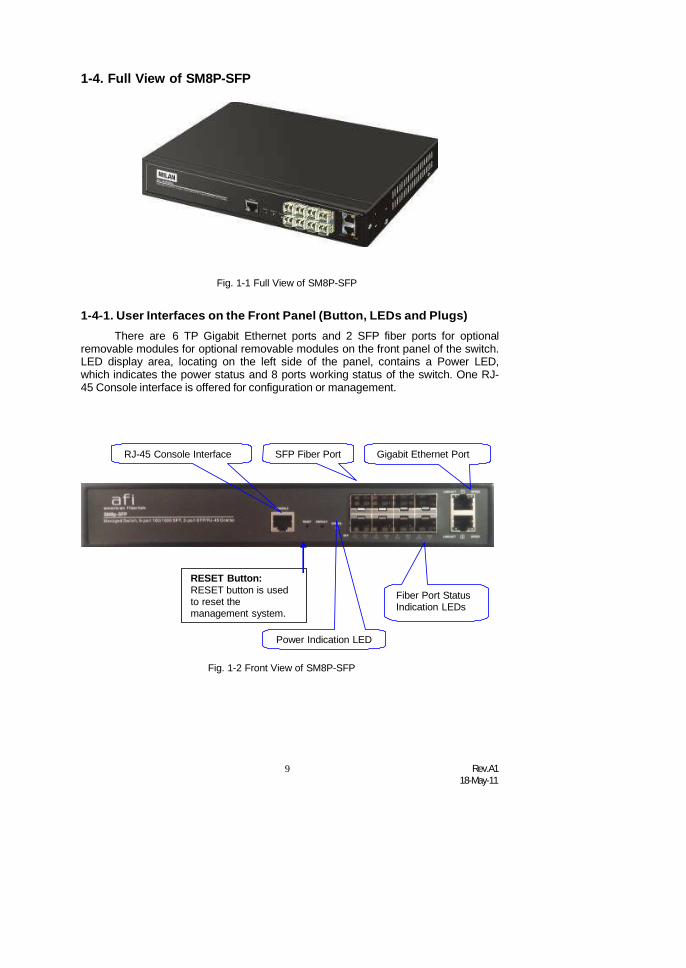
1-4. Full View of SM8P-SFP
Fig. 1-1 Full View of SM8P-SFP
1-4-1. User Interfaces on the Front Panel (Button, LEDs and Plugs)There are 6 TP Gigabit Ethernet ports and 2 SFP fiber ports for optional
removable modules for optional removable modules on the front panel of the switch.LED display area, locating on the left side of the panel, contains a Power LED,which indicates the power status and 8 ports working status of the switch. One RJ-45 Console interface is offered for configuration or management.
RJ-45 Console Interface SFP Fiber Port Gigabit Ethernet Port
RESET Button:RESET button is usedto reset themanagement system.
Fiber Port StatusIndication LEDs
Power Indication LED
Fig. 1-2 Front View of SM8P-SFP

Rev.A118-May-11
10
• LED Indicators
LED Color FunctionSystem LED
POWER Green Lit when power is on and good
100/1000 SFP Port 1 to 8 LED
LINK/ACT Green/Amber
Lit Green when SFP link on 1000Mbps speedLit Amber when SFP link on 100Mbps speedBlinks when any traffic is present
TP Port 7, 8 LEDLINK/ACT Green Lit Green when TP link good
Blinks when any traffic is present
Speed Green/Amber
Lit Green when TP link on 1000Mbps speedLit Amber when TP link on 100Mbps speedOff when 10Mbps or no link occur
Table1-1
1-4-2. AC Power Input on the Rear PanelOne socket on the rear panel is for AC power input.
AC Line 100-240V 50/60 Hz
Fig. 1-3 Rear View of SM8P-SFP

11 Rev.A118-May-11
1-5. View of the Optional ModulesIn the switch, Port 7~8 includes two types of media --- TP and SFP Fiber (LC,
BiDi LC…); this port supports 10/100/1000Mbps TP or 100/1000 Dual Speed SFPFiber with auto-detected function. 100/1000 Dual Speed SFP Fiber transceiver isused for high-speed connection expansion; the following are optional SFP typesprovided for the switch:
1000Mbps LC, MM, SFP Fiber transceiver (SFP.LC)
1000Mbps LC, SM 10km, SFP Fiber transceiver (SFP.LC.S10)
1000Mbps LC, SM 30km, SFP Fiber transceiver (SFP.LC.S30)
1000Mbps LC, SM 50km, SFP Fiber transceiver (SFP.LC.S50)
1000Mbps BiDi LC, type 2, SM 20km, SFP Fiber WDM transceiver ,1310nm (SFP.BL3.S20)
1000Mbps BiDi LC, type 1, SM 20km, SFP Fiber WDM transceiver1550nm (SFP.BL5.S20)
100Base-FX FE SFP Fiber Module, LC Multi-Mode (SFP.FLC)
100Base-FX FE SFP Fiber Module, LC Single-Mode 20km (SFP.FLC.S20)
Fig. 1-4 100/ 1000M-FX/SX/LX LC, SFP Fiber Transceiver
Fig. 1-5 Front View of 1000Base-LX BiDi LC, SFP Fiber Transceiver

Rev.A118-May-11
12
2. Installation2-1. Starting SM8P-SFP UpThis section will give users a quick start for:
- Hardware and Cable Installation
- Management Station Installation
- Software booting and configuration
2-1-1. Hardware and Cable InstallationAt the beginning, please do first:
Wear a grounding device to avoid the damage from electrostatic discharge
Be sure that power switch is OFF before you insert the power cord to powersource
• Installing Optional SFP Fiber Transceivers to the SM8P-SFP
Note: If you have no modules, please skip this section.
Fig. 2-1 Installation of Optional SFP Fiber Transceiver
• Connecting the SFP Module to the Chassis:
The optional SFP modules are hot swappable, so you can plug or unplug itbefore or after powering on.
1. Verify that the SFP module is the right model and conforms to the chassis
2. Slide the module along the slot. Also be sure that the module is properlyseated against the slot socket/connector
3. Install the media cable for network connection
4. Repeat the above steps, as needed, for each module to be installed intoslot(s)
5. Have the power ON after the above procedures are done

13 Rev.A118-May-11
• TP Port and Cable Installation
In the switch, TP port supports MDI/MDI-X auto-crossover, so both types ofcable, straight-through (Cable pin-outs for RJ-45 jack 1, 2, 3, 6 to 1, 2, 3, 6 in10/100M TP; 1, 2, 3, 4, 5, 6, 7, 8 to 1, 2, 3, 4, 5, 6, 7, 8 in Gigabit TP) andcrossed-over (Cable pin-outs for RJ-45 jack 1, 2, 3, 6 to 3, 6, 1, 2) can be used.It means you do not have to tell from them, just plug it.
Use Cat. 5 grade RJ-45 TP cable to connect to a TP port of the switch and theother end is connected to a network-aware device such as a workstation or aserver.
Repeat the above steps, as needed, for each RJ-45 port to be connected to aGigabit 10/100/1000 TP device.
Now, you can start having the switch in operation.
• Power On
The switch supports 100-240 VAC, 50-60 Hz power supply. The powersupply will automatically convert the local AC power source to DC power. It does notmatter whether any connection plugged into the switch or not when power on, evenmodules as well. After the power is on, all LED indicators will light up immediatelyand then all off except the power LED still keeps on. This represents a reset of thesystem.
• Firmware Loading
After resetting, the bootloader will load the firmware into the memory. It willtake about 30 seconds, after that, the switch will flash all the LED once andautomatically performs self-test and is in ready state.

Rev.A118-May-11
14
2-1-2. Installing Chassis to a 19-Inch Wiring Closet Rail
Fig. 2-2
Caution: Allow a proper spacing and proper air ventilation for the cooling fanat both sides of the chassis.
Wear a grounding device for electrostatic discharge. Screw the mounting accessory to the front side of the switch (See Fig. 2-2). Place the Chassis into the 19-inch wiring closet rail and locate it at the proper
position. Then, fix the Chassis by screwing it.
2-1-3. Cabling RequirementsTo help ensure a successful installation and keep the network performance
good, please take a care on the cabling requirement. Cables with worsespecification will render the LAN to work poorly.
2-1-3-1. Cabling Requirements for TP Ports
For Fast Ethernet TP network connection The grade of the cable must be Cat. 5 or Cat. 5e with a maximum length of
100 meters. Gigabit Ethernet TP network connection
The grade of the cable must be Cat. 5 or Cat. 5e with a maximum length of100 meters. Cat. 5e is recommended.
2-1-3-2. Cabling Requirements for 100/1000M SX/LX SFP ModuleIt is more complex and comprehensive contrast to TP cabling in the fiber
media. Basically, there are two categories of fiber, multi mode (MM) and singlemode (SM). The later is categorized into several classes by the distance it supports.They are SX, LX, LHX, XD, and ZX. From the viewpoint of connector type, theremainly are LC and BIDI LC.

15 Rev.A118-May-11
Gigabit Fiber with multi-mode LC SFP module
Gigabit Fiber with single-mode LC SFP module
100Base-FX FE SFP Fiber Module, LC Multi-Mode
100Base-FX FE SFP Fiber Module, LC Single-Mode
Gigabit Fiber with BiDi LC 1310nm SFP module
Gigabit Fiber with BiDi LC 1550nm SFP module
The following table lists the types of fiber that we support and those else notlisted here are available upon request.
Multi-mode Fiber Cable and Modal Bandwidth
Multi-mode 62.5/125m Multi-mode 50/125mModal
Bandwidth Distance ModalBandwidth Distance
160MHz-Km 220m 400MHz-Km 500m
IEEE 802.3zGigabit Ethernet1000SX 850nm
200MHz-Km 275m 500MHz-Km 550m
Single-mode Fiber 9/125m
Single-mode transceiver 1310nm 10, 30Km1000Base-LX/LHX/XD/ZX
Single-mode transceiver 1550nm 50Km
TX(Transmit) 1310nmSingle-Mode*20Km RX(Receive) 1550nm
TX(Transmit) 1550nm
1000Base-LXSingle Fiber(BIDI LC) Single-Mode
*20Km RX(Receive) 1310nmTable2-1
2-1-3-3. Switch Cascading in Topology• Takes the Delay Time into Account
Theoretically, the switch partitions the collision domain for each port in switchcascading that you may up-link the switches unlimitedly. In practice, the networkextension (cascading levels & overall diameter) must follow the constraint of theIEEE 802.3/802.3u/802.3z and other 802.1 series protocol specifications, in whichthe limitations are the timing requirement from physical signals defined by 802.3series specification of Media Access Control (MAC) and PHY, and timer from someOSI layer 2 protocols such as 802.1d, 802.1q, LACP and so on.
The fiber, TP cables and devices’ bit-time delay (round trip) are as follows:
1000Base-X TP, Fiber 100Base-TX TP 100Base-FX Fiber
Round trip Delay: 4096 Round trip Delay: 512
Cat. 5 TP Wire: 11.12/m Cat. 5 TP Wire: 1.12/m Fiber Cable: 1.0/m
Fiber Cable : 10.10/m TP to fiber Converter: 56
Bit Time unit : 1ns (1sec./1000 Mega bit) Bit Time unit: 0.01s (1sec./100 Mega bit)
Table 2-2

Rev.A118-May-11
16
Sum up all elements’ bit-time delay and the overall bit-time delay ofwires/devices must be within Round Trip Delay (bit times) in a half-duplex networksegment (collision domain). For full-duplex operation, this will not be applied. Youmay use the TP-Fiber module to extend the TP node distance over fiber optic andprovide the long haul connection.
• Typical Network Topology in Deployment
A hierarchical network with minimum levels of switch may reduce the timingdelay between server and client station. Basically, with this approach, it willminimize the number of switches in any one path; will lower the possibility ofnetwork loop and will improve network efficiency. If more than two switches areconnected in the same network, select one switch as Level 1 switch and connect allother switches to it at Level 2. Server/Host is recommended to connect to the Level1 switch. This is general if no VLAN or other special requirements are applied.
Case1: All switch ports are in the same local area network. Every port can accesseach other (See Fig. 2-3).
Fig. 2-3 No VLAN Configuration Diagram
If VLAN is enabled and configured, each node in the network that cancommunicate each other directly is bounded in the same VLAN area.
Here VLAN area is defined by what VLAN you are using. The switchsupports both port-based VLAN and tag-based VLAN. They are different in practicaldeployment, especially in physical location. The following diagram shows how itworks and what the difference they are.
Case2a: Port-based VLAN (See Fig.2-4).
Fig. 2-4 Port-based VLAN Diagram
17 Rev.A118-May-11
1. The same VLAN members could not be in different switches.2. Every VLAN members could not access VLAN members each other.3. The switch manager has to assign different names for each VLAN groups
at one switch.
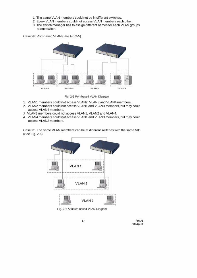
Case 2b: Port-based VLAN (See Fig.2-5).
Fig. 2-5 Port-based VLAN Diagram
1. VLAN1 members could not access VLAN2, VLAN3 and VLAN4 members.2. VLAN2 members could not access VLAN1 and VLAN3 members, but they could
access VLAN4 members.3. VLAN3 members could not access VLAN1, VLAN2 and VLAN4.4. VLAN4 members could not access VLAN1 and VLAN3 members, but they could
access VLAN2 members.
Case3a: The same VLAN members can be at different switches with the same VID(See Fig. 2-6).
Fig. 2-6 Attribute-based VLAN Diagram
Rev.A118-May-11
18
2-1-4. Configuring the Management Agent of SM8P-SFPWe offer you three ways to startup the switch management function. They
are RJ-45 console, CLI, and Web. Users can use any one of them to monitor andconfigure the switch. You can touch them through the following procedures.
Section 2-1-4-1: Configuring the Management Agent of SM8P-SFP through theConsole RJ-45 Port
Section 2-1-4-2: Configuring the Management Agent of SM8P-SFP through theEthernet Port
Note: Please first modify the IP address, Subnet mask, Default gateway and DNSthrough RJ-45 console, and then do the next.
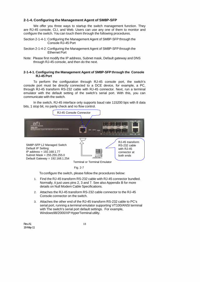
2-1-4-1. Configuring the Management Agent of SM8P-SFP through the ConsoleRJ-45 Port
To perform the configuration through RJ-45 console port, the switch’sconsole port must be directly connected to a DCE device, for example, a PC,through RJ-45 transform RS-232 cable with RJ-45 connector. Next, run a terminalemulator with the default setting of the switch’s serial port. With this, you cancommunicate with the switch.
In the switch, RJ-45 interface only supports baud rate 115200 bps with 8 databits, 1 stop bit, no parity check and no flow control.
RJ-45 Console Connector
SM8P-SFP L2 Managed SwitchDefault IP Setting:IP address = 192.168.1.77Subnet Mask = 255.255.255.0Default Gateway = 192.168.1.254
Terminal or Terminal Emulator
Fig. 2-7
RJ-45 transformRS-232 cablewith RJ-45connector atboth ends
To configure the switch, please follow the procedures below:
1. Find the RJ-45 transform RS-232 cable with RJ-45 connector bundled.Normally, it just uses pins 2, 3 and 7. See also Appendix B for moredetails on Null Modem Cable Specifications.
2. Attaches the RJ-45 transform RS-232 cable connector to the RJ-45Console connector on the switch.
3. Attaches the other end of the RJ-45 transform RS-232 cable to PC’sserial port, running a terminal emulator supporting VT100/ANSI terminalwith The switch’s serial port default settings. For example,Windows98/2000/XP HyperTerminal utility.

19 Rev.A118-May-11
Note: The switch’s serial port default settings are listed as follows:Baud rate 115200Stop bits 1Data bits 8Parity NFlow control none
4. When you complete the connection, then press <Enter> key. The loginprompt will be shown on the screen. The default username andpassword are shown as below:
Username = admin Password = root
• Set IP Address, Subnet Mask and Default Gateway IP Address
Please refer to Fig. 2-7 CLI Management for details about ex-factory IPsetting. They are default setting of IP address. You can first either configure your PCIP address or change IP address of the switch, next to change the IP address ofdefault gateway and subnet mask.
For example, your network address is 10.1.1.0, and subnet mask is255.255.255.0. You can change the switch’s default IP address 192.168.1.77 to10.1.1.1 and set the subnet mask to be 255.255.255.0. Then, choose your defaultgateway, may be it is 10.1.1.254.
Default Value SM8P-SFP Your Network SettingIP Address 192.168.1.77 10.1.1.1Subnet 255.255.255.0 255.255.255.0Default Gateway 192.168.1.254 10.1.1.254
Table 2-3
After completing these settings in the switch, it will reboot to have theconfiguration taken effect. After this step, you can operate the management throughthe network, no matter it is from a web browser or Network Management System(NMS).
SM8P-SFP
SM8P-SFP
Fig. 2-8 the Login Screen for CLI

Rev.A118-May-11
20
2-1-4-2. Configuring the Management Agent of SM8P-SFP through theEthernet Port
There are three ways to configure and monitor the switch through theswitch’s Ethernet port. They are CLI, Web browser and SNMP manager. The userinterface for the last one is NMS dependent and does not cover here. We justintroduce the first two types of management interface.
SM8P-SFP L2 Managed SwitchDefault IP Setting:IP = 192.168.1.77Subnet Mask = 255.255.255.0Default Gateway = 192.168.1.254
Assign a reasonable IP address,For example:IP = 192.168.1.100Subnet Mask = 255.255.255.0Default Gateway = 192.168.1.254
Fig. 2-9
Ethernet LAN
• Managing SM8P-SFP through Ethernet PortBefore you communicate with the switch, you have to finish first the
configuration of the IP address or to know the IP address of the switch. Then,follow the procedures listed below.
1. Set up a physical path between the configured the switch and a PC by aqualified UTP Cat. 5 cable with RJ-45 connector.
Note: If PC directly connects to the switch, you have to setup the samesubnet mask between them. But, subnet mask may be different for the PCin the remote site. Please refer to Fig. 2-9 about the switch’s default IPaddress information.
2. Run CLI or web browser and follow the menu. Please refer to Chapter 3and Chapter 4.
Fig. 2-10 the Login Screen for Web

21 Rev.A118-May-11
0
2-1-5. IP Address Assignment
For IP address configuration, there are three parameters needed to be filledin. They are IP address, Subnet Mask, Default Gateway and DNS.
IP address:
The address of the network device in the network is used for internetworkingcommunication. Its address structure looks is shown in the Fig. 2-11. It is “classful”because it is split into predefined address classes or categories.
Each class has its own network range between the network identifier andhost identifier in the 32 bits address. Each IP address comprises two parts: networkidentifier (address) and host identifier (address). The former indicates the networkwhere the addressed host resides, and the latter indicates the individual host in thenetwork which the address of host refers to. And the host identifier must be uniquein the same LAN. Here the term of IP address we used is version 4, known as IPv4.
32 bits
Network identifier Host identifier
Fig. 2-11 IP address structure
With the classful addressing, it divides IP address into three classes, class A,class B and class C. The rest of IP addresses are for multicast and broadcast. Thebit length of the network prefix is the same as that of the subnet mask and isdenoted as IP address/X, for example, 192.168.1.0/24. Each class has its addressrange described below.
Class A:
Address is less than 126.255.255.255. There are a total of 126 networks canbe defined because the address 0.0.0.0 is reserved for default route and127.0.0.0/8 is reserved for loopback function.
Bit # 0 1 7 8 31
Network address Host address
Class B:
IP address range between 128.0.0.0 and 191.255.255.255. Each class Bnetwork has a 16-bit network prefix followed 16-bit host address. There are 16,384(2^14)/16 networks able to be defined with a maximum of 65534 (2^16 –2) hostsper network.

Rev.A118-May-11
22
10
Bit # 01 2 15 16 31
Network address Host address
Class C:
IP address range between 192.0.0.0 and 223.255.255.255. Each class Cnetwork has a 24-bit network prefix followed 8-bit host address. There are2,097,152 (2^21)/24 networks able to be defined with a maximum of 254 (2^8 –2)hosts per network.
Bit # 0 1 2 3 23 24 31
Class D and E:
110
Network address Host address
Class D is a class with first 4 MSB (Most significance bit) set to 1-1-1-0 andis used for IP Multicast. See also RFC 1112. Class E is a class with first 4 MSB setto 1-1-1-1 and is used for IP broadcast.
According to IANA (Internet Assigned Numbers Authority), there are threespecific IP address blocks reserved and able to be used for extending internalnetwork. We call it Private IP address and list below:
Class A 10.0.0.0 --- 10.255.255.255Class B 172.16.0.0 --- 172.31.255.255Class C 192.168.0.0 --- 192.168.255.255
Please refer to RFC 1597 and RFC 1466 for more information.
Subnet mask:
It means the sub-division of a class-based network or a CIDR block. Thesubnet is used to determine how to split an IP address to the network prefix and thehost address in bitwise basis. It is designed to utilize IP address more efficiently andease to manage IP network.
For a class B network, 128.1.2.3, it may have a subnet mask 255.255.0.0 indefault, in which the first two bytes is with all 1s. This means more than 60thousands of nodes in flat IP address will be at the same network. It’s too large tomanage practically. Now if we divide it into smaller network by extending networkprefix from 16 bits to, say 24 bits, that’s using its third byte to subnet this class Bnetwork. Now it has a subnet mask 255.255.255.0, in which each bit of the firstthree bytes is 1. It’s now clear that the first two bytes is used to identify the class Bnetwork, the third byte is used to identify the subnet within this class B network and,of course, the last byte is the host number.

23 Rev.A118-May-11
Network Subnet
10000000.00000001.00000010.1 0000000
25 bits
All 0s = 128.1.2.128 1All 1s= 128.1.2.255
1
Not all IP address is available in the sub-netted network. Two specialaddresses are reserved. They are the addresses with all zero’s and all one’s hostnumber. For example, an IP address 128.1.2.128, what IP address reserved will belooked like? All 0s mean the network itself, and all 1s mean IP broadcast.
128.1.2.128/25
00000001111111
In this diagram, you can see the subnet mask with 25-bit long,255.255.255.128, contains 126 members in the sub-netted network. Another is thatthe length of network prefix equals the number of the bit with 1s in that subnet mask.With this, you can easily count the number of IP addresses matched. The followingtable shows the result.
Prefix Length No. of IP matched No. of Addressable IP
/32 1 -
/31 2 -
/30 4 2
/29 8 6
/28 16 14
/27 32 30
/26 64 62
/25 128 126
/24 256 254
/23 512 510
/22 1024 1022
/21 2048 2046
/20 4096 4094
/19 8192 8190
/18 16384 16382
/17 32768 32766
/16 65536 65534
Table 2-4
Rev.A118-May-11
24
According to the scheme above, a subnet mask 255.255.255.0 will partition anetwork with the class C. It means there will have a maximum of 254 effectivenodes existed in this sub-netted network and is considered a physical network in anautonomous network. So it owns a network IP address which may looks like168.1.2.0.
With the subnet mask, a bigger network can be cut into small pieces ofnetwork. If we want to have more than two independent networks in a worknet, apartition to the network must be performed. In this case, subnet mask must beapplied.
For different network applications, the subnet mask may look like255.255.255.240. This means it is a small network accommodating a maximum of15 nodes in the network.
Default gateway:
For the routed packet, if the destination is not in the routing table, all thetraffic is put into the device with the designated IP address, known as default router.Basically, it is a routing policy. The gateway setting is used for Trap Events Hostonly in the switch.
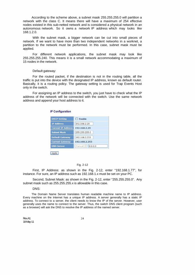
For assigning an IP address to the switch, you just have to check what the IPaddress of the network will be connected with the switch. Use the same networkaddress and append your host address to it.
Fig. 2-12
First, IP Address: as shown in the Fig. 2-12, enter “192.168.1.77”, forinstance. For sure, an IP address such as 192.168.1.x must be set on your PC.
Second, Subnet Mask: as shown in the Fig. 2-12, enter “255.255.255.0”. Anysubnet mask such as 255.255.255.x is allowable in this case.
DNS:The Domain Name Server translates human readable machine name to IP address.
Every machine on the Internet has a unique IP address. A server generally has a static IPaddress. To connect to a server, the client needs to know the IP of the server. However, usergenerally uses the name to connect to the server. Thus, the switch DNS client program (suchas a browser) will ask the DNS to resolve the IP address of the named server.
25 Rev.A118-May-11
2-2. Typical Applications
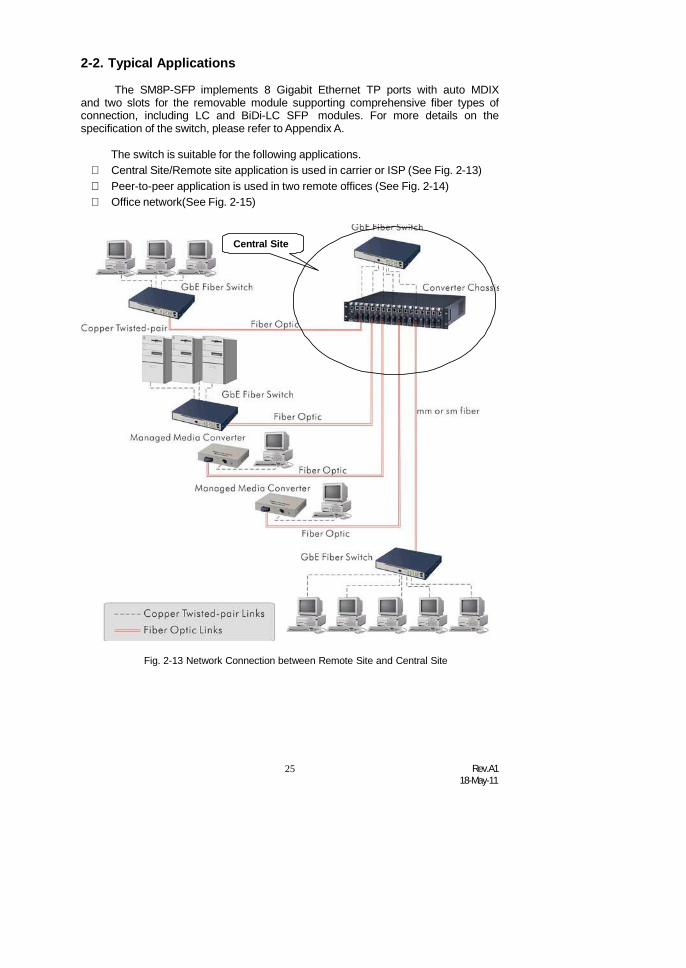
The SM8P-SFP implements 8 Gigabit Ethernet TP ports with auto MDIXand two slots for the removable module supporting comprehensive fiber types ofconnection, including LC and BiDi-LC SFP modules. For more details on thespecification of the switch, please refer to Appendix A.
The switch is suitable for the following applications. Central Site/Remote site application is used in carrier or ISP (See Fig. 2-13) Peer-to-peer application is used in two remote offices (See Fig. 2-14) Office network(See Fig. 2-15)
Central Site
Fig. 2-13 Network Connection between Remote Site and Central Site
Rev.A118-May-11
26
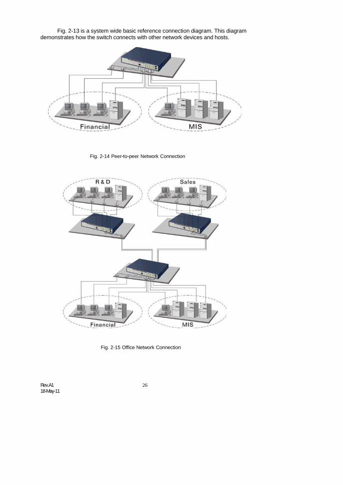
Fig. 2-13 is a system wide basic reference connection diagram. This diagramdemonstrates how the switch connects with other network devices and hosts.
Fig. 2-14 Peer-to-peer Network Connection
Fig. 2-15 Office Network Connection

27 Rev.A118-May-11
3. Operation of Web-basedManagement
This chapter instructs you how to configure and manage the SM8P-SFPthrough the web user interface it supports, to access and manage the 6-Port100/1000 Dual Speed SFP and 2-Port Gigabit TP/ (100/1000M) SFP Fibermanagement Ethernet switch. With this facility, you can easily access and monitorthrough any one port of the switch all the status of the switch, including MIBs status,each port activity, Spanning tree status, port aggregation status, multicast traffic,VLAN and priority status, even illegal access record and so on.
The default values of the managed switch are listed in the table below:
IP Address 192.168.1.77255.255.255.0
192.168.1.254
admin
Subnet MaskDefault GatewayUsernamePassword root
Table 3-1
After the managed switch has been finished configuration in the CLI via theswitch’s serial interface, you can browse it. For instance, type http://192.168.1.77 inthe address row in a browser, it will show the following screen (see Fig.3-1) and askyou inputting username and password in order to login and access authentication.The default username and password are both “admin”. For the first time to use,please enter the default username and password, then click the <Login> button.The login process now is completed.
Just click the link of “Forget Password” in WebUI (See Fig. 3-1) or input“Ctrl+Z” in CLI’s login screen (See Fig. 4-1~4-2) in case the user forgets themanager’s password. Then, the system will display a serial No. for the user. Writedown this serial No. and contact your vendor, the vendor will give you a temporarypassword. Use this new password as ID and Password, and it will allow the user tologin the system with manager authority temporarily. Due to the limit of this newpassword, the user only can login the system one time, therefore, please modifyyour password immediately after you login in the system successfully.
In this login menu, you have to input the complete username and passwordrespectively, the switch will not give you a shortcut to username automatically. Thislooks inconvenient, but safer.
In the switch, it supports a simple user management function allowing onlyone administrator to configure the system at the same time. If there are two or moreusers using administrator’s identity, the switch will allow the only one who logins firstto configure the system. The rest of users, even with administrator’s identity, canonly monitor the system. For those who have no administrator’s identity, can onlymonitor the system. There are only a maximum of three users able to loginsimultaneously in the switch.

Rev.A118-May-11
28
To optimize the display effect, we recommend you use Microsoft IE 6.0above, Netscape V7.1 above or FireFox V1.00 above and have the resolution1024x768. The switch supported neutral web browser interface.
In Fig. 3-2, for example, left section is the whole function tree with web userinterface and we will travel it through this chapter.
Fig. 3-1

29 Rev.A118-May-11
3-1. Web Management Home OverviewAfter you login, the switch shows you the system information as Fig. 3-2. This
page is default and tells you the basic information of the system, including “ModelName”, “System Description”, “Location”, “Contact”, “Device Name”,“System Up Time”, “Current Time”, “BIOS Version”, “Firmware Version”,“Hardware-Mechanical Version”, “Serial Number”, “Host IP Address”, “HostMac Address”, “Device Port”, “RAM Size” , “Flash Size” and “CPU Load”.With this information, you will know the software version used, MAC address, serialnumber, how many ports good and so on. This is helpful while malfunctioning.
SM8P-SFP
Fig. 3-2

Rev.A118-May-11
30
• The Information of Page Layout
On the top side, it shows the front panel of the switch. In the front panel, thelinked ports will display green; as to the ports, which are link off, they will bedark. For the optional modules, the slot will show only a cover plate if nomodule exists and will show a module if a module is present. The image ofmodule depends on the one you inserted. The same, if disconnected, the portwill show just dark, if linked, green. (See Fig. 3-3)
Fig. 3-3 port detail information
In Fig. 3-3, it shows the basic information of the clicked port. With this, you’llsee the information about the port status, traffic status and bandwidth rating foregress and ingress respectively.
On the left-top corner, there is a pull-down list for Auto Logout. For the sake ofsecurity, we provide auto-logout function to protect you from illegal user as youare leaving. If you do not choose any selection in Auto Logout list, it meansyou turn on the Auto Logout function and the system will be logged outautomatically when no action on the device 3 minutes later. If OFF is chosen,the screen will keep as it is. Default is ON.
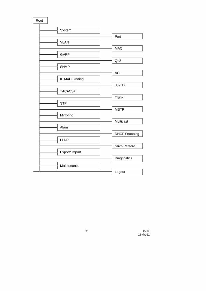
On the left side, the main menu tree for web is listed in the page. They arehierarchical menu. Open the function folder, a sub-menu will be shown. Thefunctions of each folder are described in its corresponded section respectively.When clicking it, the function is performed. The following list is the fullfunctiontree for web user interface.
31 Rev.A118-May-11
Root
System
Port
VLAN
MAC
GVRP
QoS
SNMP
ACL
IP MAC Binding
802.1X
TACACS+
Trunk
STP
MSTP
Mirroring
Multicast
Alam
DHCP Snooping
LLDP
Save/Restore
Export/ Import
Diagnostics
Maintenance
Logout

Rev.A118-May-11
32
3-1-1. System InformationFunction name:
System Information
Function description:
Show the basic system information.
SM8P-SFP
SM8P-SFP
Parameter description:
Model name:
Fig. 3-4
The model name of this device.
System description:
As it is, this tells what this device is. Here, it is “Managed Switch, 6port 100/1000 SFP, 2 Port SFP/ RJ-45 Combo”.
Location:
Basically, it is the location where this switch is put. User-defined.
Contact:
For easily managing and maintaining device, you may write down thecontact person and phone here for getting help soon. You can configurethis parameter through the device’s user interface or SNMP.
Device name:
The name of the switch. User-defined. Default is SM8P-SFP.

33 Rev.A118-May-11
System up time:
The time accumulated since this switch is powered up. Its format is day,hour, minute, second.
Current time:
Show the system time of the switch. Its format: day of week, month, day,hours : minutes : seconds, year. For instance, Wed, Apr. 23, 12:10:10,2004.
BIOS version:
The version of the BIOS in this switch.
Firmware version:
The firmware version in this switch.
Hardware-Mechanical version:
The version of Hardware and Mechanical. The figure before the hyphenis the version of electronic hardware; the one after the hyphen is theversion of mechanical.
Serial number:
The serial number is assigned by the Transition.
Host IP address:
The IP address of the switch.
Host MAC address:
It is the Ethernet MAC address of the management agent in this switch.
Device Port:
Show all types and numbers of the port in the switch.
RAM size:
The size of the DRAM in this switch.
Flash size:
The size of the flash memory in this switch.
CPU Loading:
The loading of the CPU on this switch.
Rev.A118-May-11
34
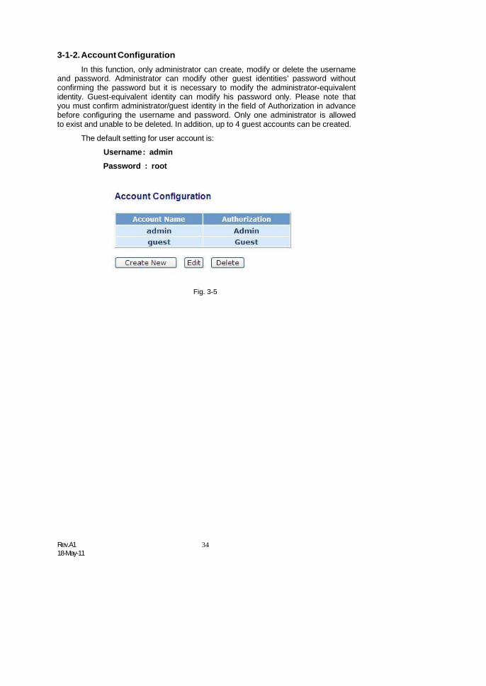
3-1-2.Account ConfigurationIn this function, only administrator can create, modify or delete the username
and password. Administrator can modify other guest identities’ password withoutconfirming the password but it is necessary to modify the administrator-equivalentidentity. Guest-equivalent identity can modify his password only. Please note thatyou must confirm administrator/guest identity in the field of Authorization in advancebefore configuring the username and password. Only one administrator is allowedto exist and unable to be deleted. In addition, up to 4 guest accounts can be created.
The default setting for user account is:
Username: adminPassword : root
Fig. 3-5

35 Rev.A118-May-11
3-1-3. Time ConfigurationThe switch provides manual and automatic ways to set the system time via
NTP. Manual setting is simple and you just input “Year”, “Month”, “Day”, “Hour”,“Minute” and “Second” within the valid value range indicated in each item. If youinput an invalid value, for example, 61 in minute, the switch will clamp the figure to59.
NTP is a well-known protocol used to synchronize the clock of the switchsystem time over a network. NTP, an internet draft standard formalized in RFC 1305,has been adopted on the system is version 3 protocol. The switch provides fourbuilt-in NTP server IP addresses resided in the Internet and an user-defined NTPserver IP address. The time zone is Greenwich-centered which uses the expressionform of GMT+/- xx hours.
Function name:
Time
Function description:
Set the system time by manual input or set it by syncing from Time servers.The function also supports daylight saving for different area’s time adjustment.
Parameter description:Fig. 3-6
Current Time:
Show the current time of the system.
Manual:
This is the function to adjust the time manually. Filling the valid figures inthe fields of Year, Month, Day, Hour, Minute and Second respectively andpress <Apply> button, time is adjusted. The valid figures for the

Rev.A118-May-11
36
parameter Year, Month, Day, Hour, Minute and Second are >=2000, 1-12,1-31, 0-23, 0-59 and 0-59 respectively. Input the wrong figure and press<Apply> button, the device will reject the time adjustment request. Thereis no time zone setting in Manual mode.
Default: Year = 2000, Month = 1, Day = 1Hour = 0, Minute = 0, Second = 0
NTP:
NTP is Network Time Protocol and is used to sync the network timebased Greenwich Mean Time (GMT). If use the NTP mode and select abuilt-in NTP time server or manually specify an user-defined NTP serveras well as Time Zone, the switch will sync the time in a short afterpressing <Apply> button. Though it synchronizes the time automatically,NTP does not update the time periodically without user’s processing.
Time Zone is an offset time off GMT. You have to select the time zonefirst and then perform time sync via NTP because the switch will combinethis time zone offset and updated NTP time to come out the local time,otherwise, you will not able to get the correct time. The switch supportsconfigurable time zone from –12 to +13 step 1 hour.
Default Time zone: +8 Hrs.
Daylight Saving:
Daylight saving is adopted in some countries. If set, it will adjust the timelag or in advance in unit of hours, according to the starting date and theending date. For example, if you set the day light saving to be 1 hour.When the time passes over the starting time, the system time will beincreased one hour after one minute at the time since it passed over. Andwhen the time passes over the ending time, the system time will bedecreased one hour after one minute at the time since it passed over.
The switch supports valid configurable day light saving time is –5 ~ +5step one hour. The zero for this parameter means it need not have toadjust current time, equivalent to in-act daylight saving. You don’t have toset the starting/ending date as well. If you set daylight saving to be non-zero, you have to set the starting/ending date as well; otherwise, thedaylight saving function will not be activated.
Default for Daylight Saving: 0.
The following parameters are configurable for the function DaylightSaving and described in detail.
Day Light Saving Start :
This is used to set when to start performing the day light saving time.
Mth:
Day:
Range is 1 ~ 12.
Default: 1
Range is 1 ~ 31.
Default: 1

37 Rev.A118-May-11
Hour:
Range is 0 ~ 23.
Default: 0
Day Light Saving End :
This is used to set when to stop performing the daylight saving time.
Mth:
Day:
Range is 1 ~ 12.
Default: 1
Range is 1 ~ 31.
Default: 1
Hour:
Range is 0 ~ 23.
Default: 0

Rev.A118-May-11
38
3-1-4. IP ConfigurationIP configuration is one of the most important configurations in the switch.
Without the proper setting, network manager will not be able to manage or view thedevice. The switch supports both manual IP address setting and automatic IPaddress setting via DHCP server. When IP address is changed, you must reboot theswitch to have the setting taken effect and use the new IP to browse for webmanagement and CLI management.
Function name:
IP Configuration
Function description:Set IP address, subnet mask, default gateway and DNS for the switch.
Fig. 3-7 IP Address Configuration
Parameter description:
DHCP Setting:
DHCP is the abbreviation of Dynamic Host Configuration Protocol. HereDHCP means a switch to turn ON or OFF the function.
The switch supports DHCP client used to get an IP address automaticallyif you set this function “Enable”. When enabled, the switch will issue therequest to the DHCP server resided in the network to get an IP address.If DHCP server is down or does not exist, the switch will issue therequest and show IP address is under requesting, until the DHCP serveris up. Before getting an IP address from DHCP server, the device will notcontinue booting procedures. If set this field “Disable”, you’ll have toinput IP address manually. For more details about IP address and DHCP,please see the Section 2-1-5 “IP Address Assignment” in this manual.
Default: Disable

39 Rev.A118-May-11
IP address:
Users can configure the IP settings and fill in new values if users set theDHCP function “Disable”. Then, click <Apply> button to update.
When DHCP is disabled, Default: 192.168.1.77
If DHCP is enabled, this field is filled by DHCP server and will not allowuser manually set it any more.
Subnet mask:
Subnet mask is made for the purpose to get more network addressbecause any IP device in a network must own its IP address, composedof Network address and Host address, otherwise can’t communicate withother devices each other. But unfortunately, the network classes A, B,and C are all too large to fit for almost all networks, hence, subnet maskis introduced to solve this problem. Subnet mask uses some bits fromhost address and makes an IP address looked Network address, Subnetmask number and host address. It is shown in the following figure. Thisreduces the total IP number of a network able to support, by the amountof 2 power of the bit number of subnet number (2^(bit number of subnetnumber)).
32 bits
NetworkID Host ID
Network ID Host ID
Subnet number
Subnet mask is used to set the subnet mask value, which should be thesame value as that of the other devices resided in the same network itattaches.
For more information, please also see the Section 2-1-5 “IP AddressAssignment” in this manual.
Default: 255.255.255.0
Default gateway:
Set an IP address for a gateway to handle those packets that do notmeet the routing rules predefined in the device. If a packet does not meetthe criteria for other pre-defined path, it must be forwarded to a defaultrouter on a default path. This means any packet with undefined IPaddress in the routing table will be sent to this device unconditionally.
Default: 192.168.1.254

Rev.A118-May-11
40
DNS:
It is Domain Name Server used to serve the translation between IPaddress and name address.
The switch supports DNS client function to re-route the mnemonic nameaddress to DNS server to get its associated IP address for accessingInternet. User can specify a DNS IP address for the switch. With this, theswitch can translate a mnemonic name address into an IP address.
There are two ways to specify the IP address of DNS. One is fixed mode,which manually specifies its IP address, the other is dynamic mode,which is assigned by DHCP server while DHCP is enabled. DNS canhelp you easily remember the mnemonic address name with themeaningful words in it. Default is no assignment of DNS address.
Default: 0.0.0.0
41 Rev.A118-May-11
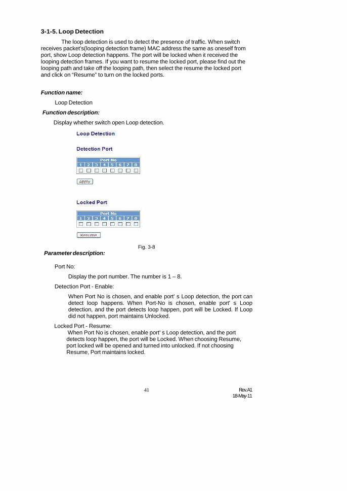
3-1-5. Loop DetectionThe loop detection is used to detect the presence of traffic. When switch
receives packet’s(looping detection frame) MAC address the same as oneself fromport, show Loop detection happens. The port will be locked when it received thelooping detection frames. If you want to resume the locked port, please find out thelooping path and take off the looping path, then select the resume the locked portand click on “Resume” to turn on the locked ports.
Function name:
Loop Detection
Function description:
Display whether switch open Loop detection.
Parameter description:Fig. 3-8
Port No:
Display the port number. The number is 1 – 8.
Detection Port - Enable:
When Port No is chosen, and enable port' s Loop detection, the port candetect loop happens. When Port-No is chosen, enable port' s Loopdetection, and the port detects loop happen, port will be Locked. If Loopdid not happen, port maintains Unlocked.
Locked Port - Resume:When Port No is chosen, enable port' s Loop detection, and the portdetects loop happen, the port will be Locked. When choosing Resume,port locked will be opened and turned into unlocked. If not choosingResume, Port maintains locked.

Rev.A118-May-11
42
AcceptDeny
3-1-6. Management PolicyThrough the management security configuration, the manager can do the
strict setup to control the switch and limit the user to access this switch.
The following rules are offered for the manager to manage the switch:
Rule 1) : When no lists exists, then it will accept all connections.
Accept-----------------------------------------------------------------------
Rule 2) : When only “accept lists” exist, then it will deny all connections,excluding the connection inside of the accepting range.
Accept Deny Accept Deny Accept-----------------------------------------------------------------------
Rule 3) : When only “deny lists” exist, then it will accept all connections,excluding the connection inside of the denying range.
Deny Accept Deny Accept Deny-----------------------------------------------------------------------
Rule 4) : When both “accept and deny” lists exist, then it will deny allconnections, excluding the connection inside of the accepting range.
Accept Deny Deny Deny Accept-----------------------------------------------------------------------
Rule 5) : When both “accept and deny” lists exist, then it will deny allconnections, excluding the connection inside of the accepting range and NOTinside of the denying range at the same time.
Accept
Deny| Acc | Deny | Acc | Deny----------------------------------------------------------------------

43 Rev.A118-May-11
Function name:
Management Security Configuration
Function description:
The switch offers Management Security Configuration function. With thisfunction, the manager can easily control the mode that the user connects tothe switch. According to the mode, users can be classified into two types:Those who are able to connect to the switch (Accept) and those who areunable to connect to the switch (Deny). Some restrictions also can be placedon the mode that the user connect to the switch, for example, we can decidethat which VLAN VID is able to be accepted or denied by the switch, the IPrange of the user could be accepted or denied by the switch, the port that theuser is allowed or not allowed to connect with the switch, or the way ofcontrolling and connecting to the switch via Http, Telnet or SNMP.
Fig. 3-9
Parameter description:Add:
Fig. 3-10
A new entry of Management Security Configuration can be created afterthe parameters as mentioned above had been setup and then press<Add> button. Of course, the existed entry also can be modified bypressing this button.
Delete:
Remove the existed entry of Management Security Configuration fromthe management security table.

Rev.A118-May-11
44
Name:
A name is composed of any letter (A-Z, a-z) and digit (0-9) with maximal8 characters.
VID:
The switch supports two kinds of options for managed valid VLAN VID,including “Any” and “Custom”. Default is “Any”. When you choose“Custom”, you can fill in VID number. The valid VID range is 1~4094.
IP Range:
The switch supports two kinds of options for managed valid IP Range,including “Any” and “Custom”. Default is “Any”. In case that” Custom”had been chosen, you can assigned effective IP range. The valid rangeis 0.0.0.0~255.255.255.255.
Incoming Port:
The switch supports two kinds of options for managed valid Port Range,including “Any” and “Custom”. Default is “Any”. You can select the portsthat you would like them to be worked and restricted in the managementsecurity configuration if ”Custom” had been chosen.
Access Type:
The switch supports two kinds of options for managed valid Access Type,including “Any” and “Custom”. Default is “Any”. “Http”, “Telnet” and“SNMP” are three ways for the access and managing the switch in casethat” Custom” had been chosen.
Action:
The switch supports two kinds of options for managed valid Action Type,including “Deny” and “Accept”. Default is “Deny”. When you choose“Deny” action, you will be restricted and refused to manage the switchdue to the “Access Type” you choose. However, while you select“Accept” action, you will have the authority to manage the switch.
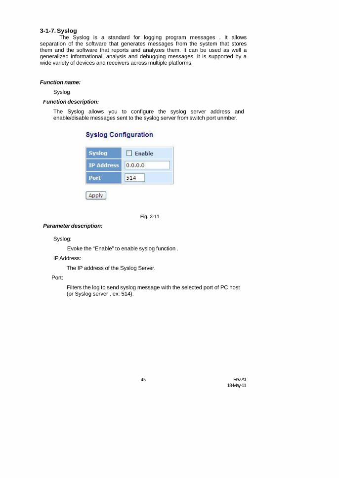
45 Rev.A118-May-11
3-1-7. SyslogThe Syslog is a standard for logging program messages . It allows
separation of the software that generates messages from the system that storesthem and the software that reports and analyzes them. It can be used as well ageneralized informational, analysis and debugging messages. It is supported by awide variety of devices and receivers across multiple platforms.
Function name:
Syslog
Function description:
The Syslog allows you to configure the syslog server address andenable/disable messages sent to the syslog server from switch port unmber.
Parameter description:Fig. 3-11
Syslog:
Evoke the “Enable” to enable syslog function .
IP Address:
The IP address of the Syslog Server.
Port:
Filters the log to send syslog message with the selected port of PC host(or Syslog server , ex: 514).

Rev.A118-May-11
46
3-1-8. System LogThe System Log provides information about system logs, including
information when the device was booted, how the ports are operating, when userslogged in, when sessions timed out, as well as other system information.
Function name:
System Log
Function description:
The Trap Log Data is displaying the log items including all SNMP Private Trapevents, SNMP Public traps and user logs occurred in the system. In the reporttable, No., Time and Events are three fields contained in each trap record.
Parameter description:Fig. 3-11
No:
Time:
Display the order number that the trap happened.
Desc:
Display the time that the trap happened.
Displays a description event recorded in the System Log.
Clear:
Clear log data.

47 Rev.A118-May-11
3-1-9. Virtual Stack
Function name:
Virtual Stack
Function description:
Virtual Stack Management(VSM) is the group management function. Throughthe proper configuration of this function, switches in the same LAN will begrouped automatically. And among these switch, one switch will be a mastermachine, and the others in this group will become the slave devices.
VSM offers a simple centralized management function. It is not necessary toremember the address of all devices, manager is capable of managing thenetwork with knowing the address of the Master machine. Instead of SNMP orTelnet UI, VSM is only available in Web UI. While one switch become theMaster, two rows of buttons for group device will appear on the top of its WebUI. By pressing these buttons, user will be allowed to connect the Web UI ofthe devices of the group in the same window without the login of these device.
The most top-left button is only for Master device(See Fig.3-9). Thebackground color of the button you press will be changed to represent that thedevice is under your management.
Note: It will remove the grouping temporarily in case that you login the switchvia the console.
The device of the group will be shown as station address ( the last number ofIP Address) + device name on the button (e.g. 196_SM8P-SFP), otherwise itwill show ” ---- “ if no corresponding device exists.
Once the devices join the group successfully, then they are merely able to bemanaged via Master device, and user will fail to manage them viatelnet/console/web individually.
Up to 16 devices can be grouped for VSM, however, only one Master isallowed to exist in each group. For Master redundancy, user may configuremore than two devices as Master device, however, the Master device with thesmaller MAC value will be the Master one. All of these 16 devices canbecome Master device and back up with each other .
Fig. 3-10-1

Rev.A118-May-11
48
Parameter description:
State:It is used for the activation or de-activation of VSM. Default is Enable.
Role:
The role that the switch would like to play in virtual stack. Two types ofroles, including master and slave are offered for option. Default is Master.
Group ID:It is the group identifier (GID) which signs for VSM. Valid letters are A-Z,a-z, 0-9, “ - “ and “_” characters. The maximal length is 15 characters.

49 Rev.A118-May-11
3-2. Port ConfigurationFour functions, including Port Status, Port Configuration, Simple Counter and
Detail Counter are contained in this function folder for port monitor andmanagement. Each of them will be described in detail orderly in the followingsections.
Port Configuration
Configuration
Status
Simple Counter
Detail Counter
Power saving
3-2-1. Port ConfigurationPort Configuration is applied to change the setting of each port. In this
configuration function, you can set/reset the following functions. All of them are
described in detail below.
Function name:
Port Configuration
Function description:
It is used to set each port’s operation mode. The switch supports 3 parametersfor each port. They are state, mode and flow control.
Fig. 3-12

Rev.A118-May-11
50
Parameter description:
Speed:
Set the speed and duplex of the port. In speed, if the media is 1Gbpsfiber, it is always 1000Mbps and the duplex is full only. If the media is TP,the Speed/Duplex is comprised of the combination of speed mode,10/100/1000Mbps, and duplex mode, full duplex and half duplex. Thefollowing table summarized the function the media supports.
Media type NWay Speed Duplex1000M TP ON/OFF 10/100/1000M Full for all, Half for 10/1001000M Fiber ON/OFF 1000M Full
In Auto-negotiation mode, no default value. In Forced mode, defaultvalue depends on your setting.
Flow Control:
There are two modes to choose in flow control, including Enable andDisable. If flow control is set Enable, both parties can send PAUSE frameto the transmitting device(s) if the receiving port is too busy to handle.When it is set Disable, there will be no flow control in the port. It dropsthe packet if too much to handle.
Maximum Frame:
This module offer 1518~9600 (Bytes) length to make the long packet.
Excessive Collision Mode:
There are two modes to choose when excessive collision happen in half-duplex condition as below:
Discard: The “Discard” mode determines whether the MAC drop framesafter an excessive collision has occurred. If set, a frame is dropped afterexcessive collisions. This is IEEE Std 802.3 half-duplex flow controloperation.
Restart: The “Restart” mode determines whether the MAC retransmitsframes after an excessive collision has occurred. If set, a frame is notdropped after excessive collisions, but the backoff sequence is restarted.This is a violation of IEEE Std 802.3, but is useful in non-dropping half-duplex flow control operation.
Description:
Description of device ports can not include “ # % & ‘ + \.

51 Rev.A118-May-11
3-2-2.Port StatusThe function Port Status gathers the information of all ports’ current status
and reports it by the order of port number, media, link status, port state, Auto-Negotiation status, speed/duplex, Rx Pause and Tx Pause. An extra media typeinformation for the module ports 21 and 24 is also offered (See Fig. 3-14).
Function name:
Port Status
Function Description:
Report the latest updated status of all ports in this switch. When any one of theports in the switch changes its parameter displayed in the page, it will beautomatically refreshed the port current status about every 5 seconds.
Parameter Description:Fig. 3-13
Port:
Display the port number. The number is 1 – 8. Both port 7 ~ 8 areoptional modules.
State:
Display the port state. V means the port state is healthy and X means theport is failure.
Link:
Show that if the link on the port is active or not. If the link is connected toa working-well device, the Link will show the link “Up”; otherwise, it willshow “Down”. This is determined by the hardware on both devices of theconnection.
No default value.

Rev.A118-May-11
52
Speed / Duplex Mode:
Display the speed and duplex of all port. There are three speeds 10Mbps,100Mbps and 1000Mbps supported for TP media, and the duplexsupported is half duplex and full duplex. If the media is 1Gbps fiber, it is1000Mbps supported only. The status of speed/duplex mode isdetermined by 1) the negotiation of both local port and link partner in“Auto Speed” mode or 2) user setting in “Force” mode. The local port hasto be preset its capability.
Default: None, depends on the result of the negotiation.
Flow Control:
Show each port’s flow control status.
There are two types of flow control in Ethernet, Backpressure for half-duplex operation and Pause flow control (IEEE802.3x) for full-duplexoperation. The switch supports both of them.
Default: None, depends on the result of the negotiation.
Description:
network managers provide a description of device ports.
Fig. 3-14

53 Rev.A118-May-11
Parameter description of Port 7 ~ Port 8:
Connector Type:
Display the connector type, for instance, UTP, SC, ST, LC and soon.
Fiber Type:
Display the fiber mode, for instance, Multi-Mode, Single-Mode.
Tx Central Wavelength:
Display the fiber optical transmitting central wavelength, forinstance, 850nm, 1310nm, 1550nm and so on.
Baud Rate:
Display the maximum baud rate of the fiber module supported, forinstance, 10M, 100M, 1G and so on.
Vendor OUI:
Display the Manufacturer's OUI code which is assigned by IEEE.
Vendor Name:
Display the company name of the module manufacturer.
Vendor P/N:
Display the product name of the naming by module manufacturer.
Vendor Rev (Revision):
Display the module revision.
Vendor SN (Serial Number):
Show the serial number assigned by the manufacturer.
Date Code:
Show the date this SFP module was made.
Temperature:
Show the current temperature of SFP module.
Vcc:
Show the working DC voltage of SFP module.
Mon1(Bias) mA:
Show the Bias current of SFP module.
Mon2(TX PWR):
Show the transmit power of SFP module.
Mon3(RX PWR):
Show the receiver power of SFP module.

Rev.A118-May-11
54
3-2-3. Simple CounterThe function of Simple Counter collects any information and provides the
counting about the traffic of the port, no matter the packet is good or bad.
In the Fig. 3-15, the window can show all ports’ counter information at thesame time. Each data field has 20-digit long. If the counting is overflow, the counterwill be reset and restart counting. The data is updated every time interval defined bythe user. The Refresh Interval is used to set the update frequency.
Function name:
Simple Counter
Function description:
Display the summary counting of each port’s traffic, including Tx Byte, Rx Byte,Tx Packet, Rx Packet, Tx Collision and Rx Error Packet.
Fig. 3-15
Parameters description:
Packets:
Transmit::
The counting number of the packet transmitted.
Receive:
The counting number of the packet received.
Bytes:
Transmit::
Total transmitted bytes.
Receive:
Total received bytes.

55 Rev.A118-May-11
Errors:
Transmit::
Number of bad packets transmitted.
Receive:
Number of bad packets received.
Drops
Transmit::
Number of packets transmitted drop.
Receive:
Number of packets received drop.
Auto-refresh:
The simple counts will be refreshed automatically on the UI screen.
Refresh:
The simple counts will be refreshed manually when user use mouse toclick on “Refresh” button.
Clear:
The simple counts will be reset to zero when user use mouse to clickon “Clear” button.

Rev.A118-May-11
56
3-2-4. Detail CounterThe function of Detail Counter collects any information and provides the
counting about the traffic of the port, no matter the packet is good or bad.
In the Fig. 3-16, the window can show only one port counter information atthe same time. To see another port’s counter, you have to pull down the list ofSelect, then you will see the figures displayed about the port you had chosen.
Each data field has 20-digit long. If the counting is overflow, the counter willbe reset and restart counting. The data is updated every time interval defined by theuser. The valid range is 3 to 10 seconds. The Refresh Interval is used to set theupdate frequency. Default update time is 3 seconds.
Function name:Detail Counter
Function description:
Display the detailed counting number of each port’s traffic. In the Fig. 3-14, thewindow can show all counter information of each port at one time.
Parameter description:Fig. 3-16
Rx Packets:
The counting number of the packet received.
RX Octets:
Total received bytes.
Rx High Priority Packets:
Number of Rx packets classified as high priority.
Rx Low Priority Packets:
Number of Rx packets classified as low priority.
57 Rev.A118-May-11
Rx Broadcast:
Show the counting number of the received broadcast packet.
Rx Multicast:
Show the counting number of the received multicast packet.
Tx Packets:
The counting number of the packet transmitted.
TX Octets:
Total transmitted bytes.
Tx High Priority Packets:
Number of Tx packets classified as high priority.
Tx Low Priority Packets:
Number of Tx packets classified as low priority.
Tx Broadcast:
Show the counting number of the transmitted broadcast packet.
Tx Multicast:
Show the counting number of the transmitted multicast packet.
Rx 64 Bytes:
Number of 64-byte frames in good and bad packets received.
Rx 65-127 Bytes:
Number of 65 ~ 126-byte frames in good and bad packets received.
Rx 128-255 Bytes:
Number of 127 ~ 255-byte frames in good and bad packets received.
Rx 256-511 Bytes:
Number of 256 ~ 511-byte frames in good and bad packets received.
Rx 512-1023 Bytes:
Number of 512 ~ 1023-byte frames in good and bad packets received.
Rx 1024-Bytes:
Number of 1024-max_length-byte frames in good and bad packetsreceived.
Tx 64 Bytes:
Number of 64-byte frames in good and bad packets transmitted.
Tx 65-127 Bytes:
Number of 65 ~ 126-byte frames in good and bad packets transmitted.
Tx 128-255 Bytes:
Number of 127 ~ 255-byte frames in good and bad packets transmitted.
Tx 256-511 Bytes:

Rev.A118-May-11
58
Number of 256 ~ 511-byte frames in good and bad packets transmitted.
Tx 512-1023 Bytes:
Number of 512 ~ 1023-byte frames in good and bad packets transmitted.
Tx 1024-Bytes:
Number of 1024-max_length-byte frames in good and bad packetstransmitted.
Rx CRC/Alignment:
Number of Alignment errors and CRC error packets received.
Rx Undersize:
Number of short frames (<64 Bytes) with valid CRC.
Rx Oversize:
Number of long frames(according to max_length register) with valid CRC.
Rx Fragments:
Number of short frames (< 64 bytes) with invalid CRC.
Rx Jabber:
Number of long frames(according tomax_length register) with invalidCRC.
Rx Drops:
Frames dropped due to the lack of receiving buffer.
Rx Errors:
Number of the error packet received.
Tx Collisions:
Number of collisions transmitting frames experienced.
Tx Drops:
Number of frames dropped due to excessive collision, late collision, orframe aging.
Tx FIFO Drops:
Number of frames dropped due to the lack of transmitting buffer.
Auto-refresh:
The detail counts will be refreshed automatically on the UI screen.
Refresh:
The detail counts will be refreshed manually when user use mouse toclick on “Refresh” button.
Clear:The detail counts will be reset to zero when user use mouse to click on “Clear”button
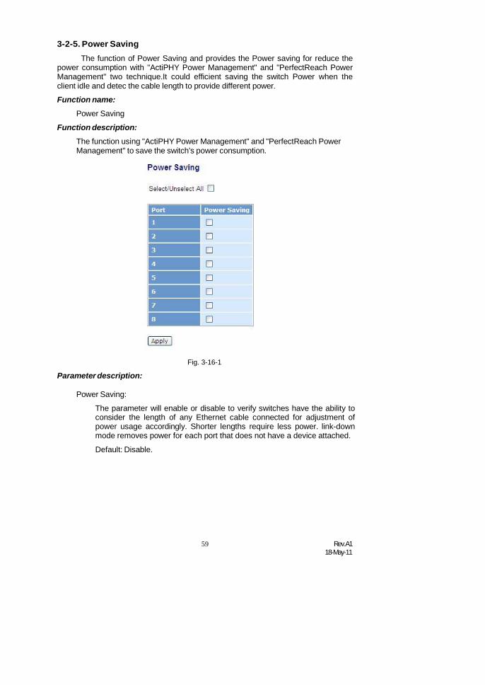
59 Rev.A118-May-11
3-2-5. Power SavingThe function of Power Saving and provides the Power saving for reduce the
power consumption with "ActiPHY Power Management" and "PerfectReach PowerManagement" two technique.It could efficient saving the switch Power when theclient idle and detec the cable length to provide different power.
Function name:
Power Saving
Function description:
The function using "ActiPHY Power Management" and "PerfectReach PowerManagement" to save the switch’s power consumption.
Parameter description:Fig. 3-16-1
Power Saving:
The parameter will enable or disable to verify switches have the ability toconsider the length of any Ethernet cable connected for adjustment ofpower usage accordingly. Shorter lengths require less power. link-downmode removes power for each port that does not have a device attached.
Default: Disable.

Rev.A118-May-11
60
3-3. VLANThe switch supports Tag-based VLAN (802.1Q) and Port-based VLAN.
Support 4094 active VLANs and VLAN ID 1~4094. VLAN configuration is used topartition your LAN into small ones as your demand. Properly configuring it, you cangain not only improving security and increasing performance but greatly reducingVLAN management.
3-3-1. VLAN Mode
Function name:
VLAN Mode Setting
Function description:
The VLAN Mode Selection function includes five modes: Port-based, Tag-based, Metro Mode, Double-tag and Disable, you can choose one of them bypulling down list and selecting an item. Then, click <Apply> button, thesettings will take effect immediately.
Parameter description:
VLAN Mode:
Port-based:
Fig. 3-17
Port-based VLAN is defined by port. Any packet coming in or outgoingfrom any one port of a port-based VLAN will be accepted. No filteringcriterion applies in port-based VLAN. The only criterion is the physicalport you connect to. For example, for a port-based VLAN namedPVLAN-1 contains port members Port 1&2&3&4. If you are on the port1, you can communicate with port 2&3&4. If you are on the port 5, thenyou cannot talk to them. Each port-based VLAN you built up must beassigned a group name. This switch can support up to maximal 24 port-based VLAN groups.
Tag-based:
Tag-based VLAN identifies its member by VID. This is quite differentfrom port-based VLAN. If there are any more rules in ingress filtering listor egress filtering list, the packet will be screened with more filteringcriteria to determine if it can be forwarded. The switch supportssupplement of 802.1q. For more details, please see the section VLANin Chapter 3.
Each tag-based VLAN you built up must be assigned VLAN name andVLAN ID. Valid VLAN ID is 1-4094. User can create total up to 4094Tag VLAN groups.

61 Rev.A118-May-11
3-3-2. Tag-based Group
Function name:
Tag-based Group Configuration
Function description:
It shows the information of existed Tag-based VLAN Groups, You can alsoeasily create, edit and delete a Tag-based VLAN group by pressing <Add>,<Edit> and <Delete> function buttons. User can add a new VLAN group byinputting a new VLAN name and VLAN ID.
Parameter description:Fig. 3-18
VLAN Name:
The name defined by administrator is associated with a VLAN group.Valid letters are A-Z, a-z, 0-9, “ - “ and “_” characters. The maximallength is 15 characters.
VLAN ID:
VLAN identifier. Each tag-based VLAN group has a unique VID. Itappears only in tag-based and Double-tag mode.
IGMP Proxy:
IGMP proxy enables the switch to issue IGMP host messages on behalfof hosts that the system discovered through standard IGMP interfaces.The system acts as a proxy for its hosts. This switch can be set IGMPfunction “Enable” or “Disable” by VLAN group. If the VLAN groupIGMP proxy is disabled, the switch will stop the exchange of IGMPmessages in the VLAN group members. If the VLAN group IGMP proxyis enabled, the switch will support the exchange of IGMP messages inthe VLAN group members and follow up IGMP proxy router portconfiguration, which connects to a router closer to the root of the tree.This interface is the upstream interface. The router on the upstreaminterface should be running IGMP. You enable IGMP on the interfacesthat connect the system to its hosts that are farther away from the root ofthe tree. These interfaces are known as downstream interfaces. Pleaserefer to 3-15-1 for detail IGMP Proxy function description.

Rev.A118-May-11
62
Member Port:
This is used to enable or disable if a port is a member of the new addedVLAN, “Enable” means it is a member of the VLAN. Just tick the checkbox () beside the port x to enable it.
Add new VLAN:
Please click on <Add new VLAN> to create a new Tag-based VLAN.Input the VLAN name as well as VID, configure the SYM-VLAN functionand choose the member by ticking the check box beside the port No.,then, press the <Apply> button to have the setting taken effect.
Delete Group:
Fig. 3-19
Just press the <Delete> button to remove the selected group entry fromthe Tag-based group table.
Fig. 3-20
Note: If you need use PVLAN( Private VLAN) function on Switch then youneed follow up the process as below:
a. Create a VLAN as primary VLAN and the VLAN ID is 2 and evoke the PrivateVLAN to enable Private VLAN service.
b. Assign port member to the VLAN2

63 Rev.A118-May-11
Fig. 3-20-1
c. You need to assign these ports for member of port isolation.
Fig. 3-20-2
d. Press the “Save” to complete the PVLAN configuration process.

Rev.A118-May-11
64
3-3-3. Port-based Group
Function name:
Port-based Group Configuration
Function description:
It shows the information of the existed Port-based VLAN Groups. You caneasily create, edit and delete a Port-based VLAN group by pressing <Add>,<Edit> and <Delete> function buttons. User can add a new VLAN group byinputting a new VLAN name.
Fig. 3-21
Parameter description:
VLAN Name:
The name defined by administrator is associated with a VLAN group.Valid letters are A-Z, a-z, 0-9, “ - “ and “_” characters. The maximallength is 15 characters.
Member Port:
This is used to enable or disable if a port is a member of the new addedVLAN, “Enable” means it is a member of the VLAN. Just tick the checkbox () beside the port x to enable it.
Add new VLAN:
Create a new Port-based VLAN. Input the VLAN name and choose themember by ticking the check box beside the port No., then, press the<Apply> button to have the setting taken effect.
Fig. 3-22
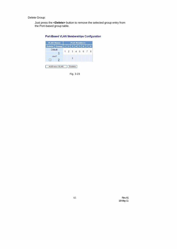
65 Rev.A118-May-11
Delete Group:
Just press the <Delete> button to remove the selected group entry fromthe Port-based group table.
Fig. 3-23

Rev.A118-May-11
66
3-3-4. Ports
Function name:
Ports (Under tag-base VLAN mode)
Function description:
In VLAN Tag Rule Setting, user can input VID number to each port. The rangeof VID number is from 1 to 4094. User also can choose ingress filtering rulesto each port. There are two ingress filtering rules which can be applied to theswitch. The Ingress Filtering Rule 1 is “forward only packets with VID matchingthis port’s configured VID”. The Ingress Filtering Rule 2 is “drop untaggedframe”. You can also select the Role of each port as Access, Trunk, or Hybrid.
Fig. 3-24
Parameter description:
Port 1-8:
Port number.
VLAN Aware:
Based on IEEE 802.1Q VLAN tag to forward packet
Ingress Filtering:
Discard other VLAN group packets, only forward this port joined VLANgroup packets
Frame Type:
All: Forward all tagged and untagged packets
Tagged: Forward tagged packets only and discard untagged packets
PVID:
This PVID range will be 1-4094. Before you set a number x as PVID, youhave to create a Tag-based VLAN with VID x. For example, if port xreceives an untagged packet, the switch will apply the PVID (assume asVID y) of port x to tag this packet, the packet then will be forwarded asthe tagged packet with VID y.

67 Rev.A118-May-11
Role:
This is an egress rule of the port. Here you can choose Access, Trunk orHybrid. Trunk means the outgoing packets must carry VLAN tag header.Access means the outgoing packets carry no VLAN tag header. Ifpackets have double VLAN tags, one will be dropped and the other willstill be left. As to Hybrid, it is similar to Trunk, and both of them will tag-out. When the port is set to Hybrid, its packets will be untagged out if theVID of the outgoing packets with tag is the same as the one in the field ofUntag VID of this port.
Untag VID:
Valid range is 1~4094. It works only when Role is set to Hybrid.
Double Tag:
Double-tag mode belongs to the tag-based mode, however, it would treatall frames as the untagged ones, which means that tag with PVID will beadded into all packets. Then, these packets will be forwarded as Tag-based VLAN. So, the incoming packets with tag will become the double-tag ones. Scroll to enable the function and default is Disable.
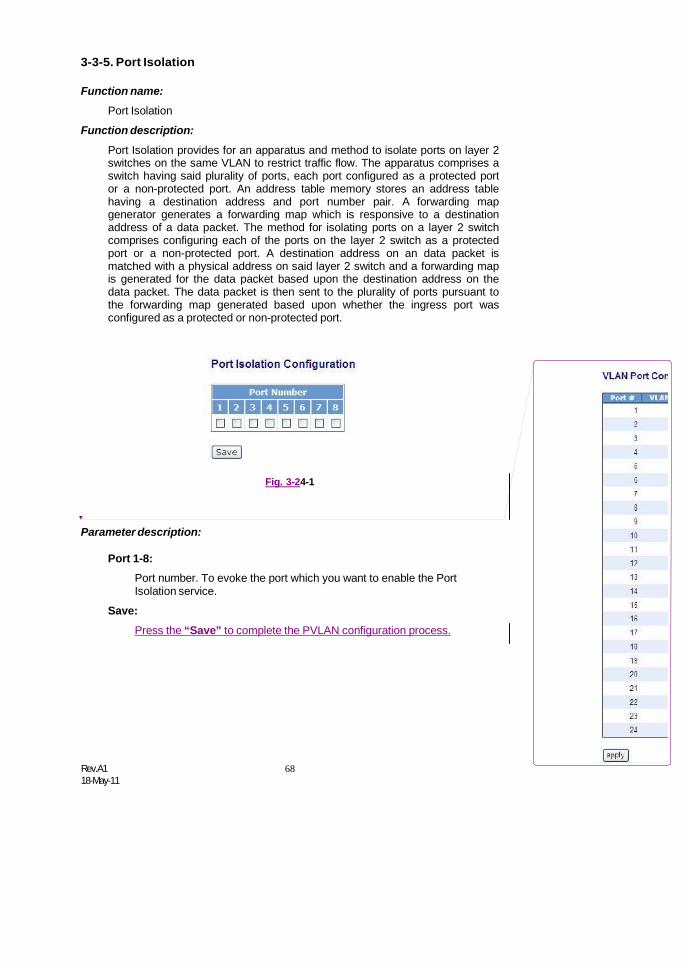
Rev.A118-May-11
68
3-3-5. Port Isolation
Function name:
Port Isolation
Function description:
Port Isolation provides for an apparatus and method to isolate ports on layer 2switches on the same VLAN to restrict traffic flow. The apparatus comprises aswitch having said plurality of ports, each port configured as a protected portor a non-protected port. An address table memory stores an address tablehaving a destination address and port number pair. A forwarding mapgenerator generates a forwarding map which is responsive to a destinationaddress of a data packet. The method for isolating ports on a layer 2 switchcomprises configuring each of the ports on the layer 2 switch as a protectedport or a non-protected port. A destination address on an data packet ismatched with a physical address on said layer 2 switch and a forwarding mapis generated for the data packet based upon the destination address on thedata packet. The data packet is then sent to the plurality of ports pursuant tothe forwarding map generated based upon whether the ingress port wasconfigured as a protected or non-protected port.
Fig. 3-24-1
Parameter description:
Port 1-8:Port number. To evoke the port which you want to enable the PortIsolation service.
Save:Press the “Save” to complete the PVLAN configuration process.

69 Rev.A118-May-11
删除的内容:

Rev.A118-May-11
70
3-3-6. Management VLAN
Function name:
Management VLAN
Function description:
To assign a specific VLAN for management purpose.
Fig. 3-25
Parameter description:
VID: Specific Management VLAN ID.

71 Rev.A118-May-11
3-4. MACMAC Table Configuration gathers many functions, including MAC Table
Information, MAC Table Maintenance, Static Forward, Static Filter and MAC Alias,which cannot be categorized to some function type. They are described below.
3-4-1. Mac Address Table
Function name:
MAC Address Table Information
Function Description:
This function can allow the user to set up the processing mechanism of MACTable. An idle MAC address exceeding MAC Address Age-out Time will beremoved from the MAC Table. The range of Age-out Time is 10-1000000seconds, and the setup of this time will have no effect on static MACaddresses.
In addition, the learning limit of MAC maintenance is able to limit the amountof MAC that each port can learn.
Fig. 3-26
Parameter description:
Aging Time:
Delete a MAC address idling for a period of time from the MAC Table,which will not affect static MAC address. Range of MAC Address AgingTime is 10-1000000 seconds. The default Aging Time is 300 seconds.

Rev.A118-May-11
72
Disable automatic aging:
Stop the MAC table aging timer, the learned MAC address will not ageout automatically
Auto:
Enable this port MAC address dynamic learning mechanism.
Disable:
Disable this port MAC address dynamic learning mechanism, onlysupport static MAC address setting.
Secure:
Disable this port MAC address dynamic learning mechanism and copythe dynamic learning packets to CPU
Save:
Save MAC Address Table configuration
Reset:
Reset MAC Address Table configuration
Flush:
Remove all non-static MAC entry

73 Rev.A118-May-11
3-4-2. Static Filter
Function name:
Static Filter
Function Description:
Static Filter is a function that denies the packet forwarding if the packet’s MACAddress is listed in the filtering Static Filter table. User can very easilymaintain the table by filling in MAC Address, VID (VLAN ID) and Alias fieldsindividually. User also can delete the existed entry by clicking <Delete> button.
Fig. 3-27
Parameter description:
MAC:
It is a six-byte long Ethernet hardware address and usually expressed byhex and separated by hyphens. For example,
00 – 40 - C7 - D6 – 00 - 02
VID:
VLAN identifier. This will be filled only when tagged VLAN is applied.Valid range is 1 ~ 4094.
Alias:
MAC alias name you assign.

Rev.A118-May-11
74
3-4-3. Static Forward
Function Name:
Static Forward
Function Description:
Static Forward is a function that allows the user in the static forward table toaccess a specified port of the switch. Static Forward table associated with aspecified port of a switch is set up by manually inputting MAC address and itsalias name.
When a MAC address is assigned to a specific port, all of the switch’s trafficssent to this MAC address will be forwarded to this port.
For adding a MAC address entry in the allowed table, you just need to fill infour parameters: MAC address, associated port, VID and Alias. Just select theexisted MAC address entry you want and click <Delete> button, you also canremove it.
Fig. 3-28
Parameter description:
MAC:
It is a six-byte long Ethernet hardware address and usually expressed byhex and separated by hyphens. For example,
00 – 40 - C7 - D6 – 00 - 01
Port No:
Port number of the switch. It is 1 ~8.
VID:
VLAN identifier. This will be filled only when tagged VLAN is applied.Valid range is 1 ~ 4094.
Alias:
MAC alias name you assign.

75 Rev.A118-May-11
3-4-4. MAC Alias
Function name:
MAC Alias
Function description:
MAC Alias function is used to let you assign MAC address a plain Englishname. This will help you tell which MAC address belongs to which user in theillegal access report. At the initial time, it shows all pairs of the existed aliasname and MAC address.
There are three MAC alias functions in this function folder, including MAC AliasAdd, MAC Alias Edit and MAC Alias Delete. You can click <Create/Edit>button to add/modify a new or an existed alias name for a specified MACaddress, or mark an existed entry to delete it. Alias name must be composedof A-Z, a-z and 0-9 only and has a maximal length of 15 characters.
Parameter description:
MAC Address:
Fig. 3-29
It is a six-byte long Ethernet hardware address and usually expressed byhex and separated by hyphens. For example,
Alias:
00 – 40 - C7 - D6 – 00 - 01
MAC alias name you assign.
Note: If there are too many MAC addresses learned in the table, werecommend you inputting the MAC address and alias name directly.
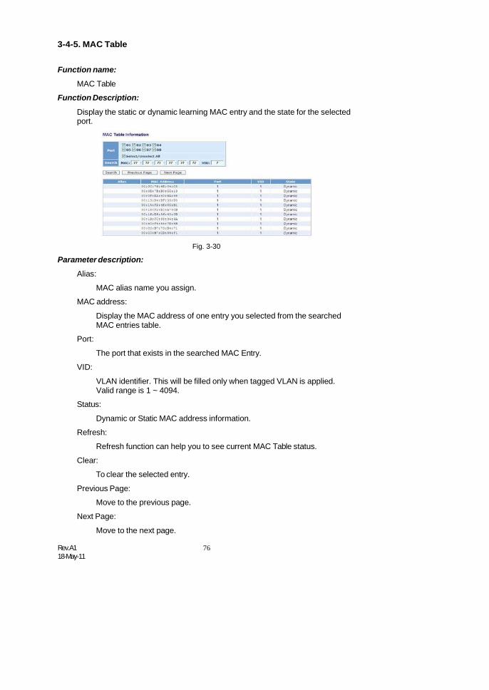
Rev.A118-May-11
76
3-4-5. MAC Table
Function name:
MAC Table
Function Description:
Display the static or dynamic learning MAC entry and the state for the selectedport.
Parameter description:
Alias:
Fig. 3-30
MAC alias name you assign.
MAC address:
Display the MAC address of one entry you selected from the searchedMAC entries table.
Port:
VID:
The port that exists in the searched MAC Entry.
VLAN identifier. This will be filled only when tagged VLAN is applied.Valid range is 1 ~ 4094.
Status:
Dynamic or Static MAC address information.
Refresh:
Refresh function can help you to see current MAC Table status.
Clear:
To clear the selected entry.
Previous Page:
Move to the previous page.
Next Page:
Move to the next page.

77 Rev.A118-May-11
3-5. GVRPGVRP is an application based on Generic Attribute Registration Protocol
(GARP), mainly used to automatically and dynamically maintain the groupmembership information of the VLANs. The GVRP offers the function providing theVLAN registration service through a GARP application. It makes use of GARPInformation Declaration (GID) to maintain the ports associated with their attributedatabase and GARP Information Propagation (GIP) to communicate amongswitches and end stations. With GID information and GIP, GVRP state machinemaintain the contents of Dynamic VLAN Registration Entries for each VLAN andpropagate these information to other GVRP-aware devices to setup and updatetheir knowledge database, the set of VLANs associated with currently activemembers, and through which ports these members can be reached.
In GVRP Configuration function folder, there are three functions supported,including GVRP Config, GVRP Counter and GVRP Group explained below.
3-5-1. Config
Function name:
GVRP Configuration
Function description:
In the function of GVRP Config, it is used to configure each port’s GVRPoperation mode, in which there are seven parameters needed to be configureddescribed below.
Parameter description:Fig. 3-31
GVRP State:
This function is simply to let you enable or disable GVRP function. Youcan pull down the list and click the <Downward> arrow key to choose“Enable” or “Disable”. Then, click the <Apply> button, the system willtake effect immediately.

Rev.A118-May-11
78
Join Time:
Used to declare the Join Time in unit of centisecond. Valid time range:20 –100 centisecond, Default: 20 centisecond.
Leave Time:
Used to declare the Leave Time in unit of centisecond. Valid time range:60 –300 centisecond, Default: 60 centisecond.
Leave All Time:
A time period for announcement that all registered device is going to bede-registered. If someone still issues a new join, then a registration willbe kept in the switch. Valid range: 1000-5000 unit time, Default: 1000 unittime.
Default Applicant Mode:
The mode here means the type of participant. There are two modes,normal participant and non-participant, provided for the user’s choice.
Normal:
It is Normal Participant. In this mode, the switch participatesnormally in GARP protocol exchanges. The default setting isNormal.
Non-Participant:
It is Non-Participant. In this mode, the switch does not send orreply any GARP messages. It just listens messages andreacts for the received GVRP BPDU.
Default Registrar Mode:
The mode here means the type of Registrar. There are three types ofparameters for registrar administrative control value, normal registrar,fixed registrar and forbidden registrar, provided for the user’s choice.
Normal:
It is Normal Registration. The Registrar responds normally toincoming GARP messages. The default setting is Normal.
Fixed:
It is Registration Fixed. The Registrar ignores all GARPmessages, and all members remain in the registered (IN)state.
Forbidden:
It is Registration Forbidden. The Registrar ignores all GARPmessages, and all members remain in the unregistered(EMPTY) state.
Restricted Mode:
This function is used to restrict dynamic VLAN be created when this portreceived GVRP PDU. There are two modes, disable and enable,provided for the user’s choice.

79 Rev.A118-May-11
Disabled:
In this mode, the switch dynamic VLAN will be created whenthis port received GVRP PDU. The default setting is Normal.
Enabled:
In this mode, the switch does not create dynamic VLAN when thisport received GVRP PDU. Except received dynamic VLAN messageof the GVRP PDU is an existed static VLAN in the switch, this portwill be added into the static VLAN members dynamically.

Rev.A118-May-11
80
3-5-2. Counter
Function name:
GVRP Counter
Function description:
All GVRP counters are mainly divided into Received and Transmitted twocategories to let you monitor the GVRP actions. Actually, they are GARPpackets.
Fig. 3-32
Parameter description:
Received:
Total GVRP Packets:
Total GVRP BPDU is received by the GVRP application.
Invalid GVRP Packets:
Number of invalid GARP BPDU is received by the GARPapplication.
LeaveAll Message Packets:
Number of GARP BPDU with Leave All message is received by theGARP application.
JoinEmpty Message Packets:
Number of GARP BPDU with Join Empty message is received bythe GARP application.
JoinIn Message Packets:
Number of GARP BPDU with Join In message is received by theGARP application.
LeaveEmpty Message Packets:Number of GARP BPDU with Leave Empty message is received bythe GARP application.

81 Rev.A118-May-11
Empty Message Packets:
Number of GARP BPDU with Empty message is received by theGARP application.
Transmitted:
Total GVRP Packets:
Total GARP BPDU is transmitted by the GVRP application.
Invalid GVRP Packets:
Number of invalid GARP BPDU is transmitted by the GVRPapplication.
LeaveAll Message Packets:
Number of GARP BPDU with Leave All message is transmittedby the GARP application.
JoinEmpty Message Packets:
Number of GARP BPDU with Join Empty message is transmitted bythe GARP application.
JoinIn Message Packets:
Number of GARP BPDU with Join In message is transmitted by theGARP application.
LeaveEmpty Message Packets:
Number of GARP BPDU with Leave Empty message is transmittedby the GARP application.
Empty Message Packets:
Number of GARP BPDU with Empty message is transmitted by theGARP application.
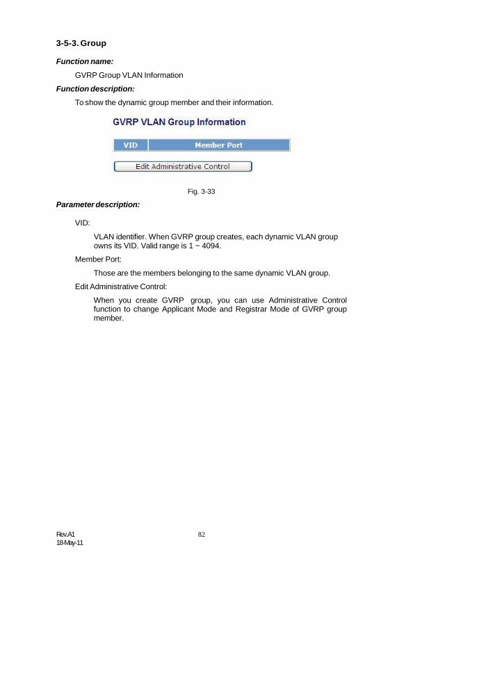
Rev.A118-May-11
82
3-5-3. Group
Function name:
GVRP Group VLAN Information
Function description:
To show the dynamic group member and their information.
Parameter description:Fig. 3-33
VID:
VLAN identifier. When GVRP group creates, each dynamic VLAN groupowns its VID. Valid range is 1 ~ 4094.
Member Port:
Those are the members belonging to the same dynamic VLAN group.
Edit Administrative Control:
When you create GVRP group, you can use Administrative Controlfunction to change Applicant Mode and Registrar Mode of GVRP groupmember.
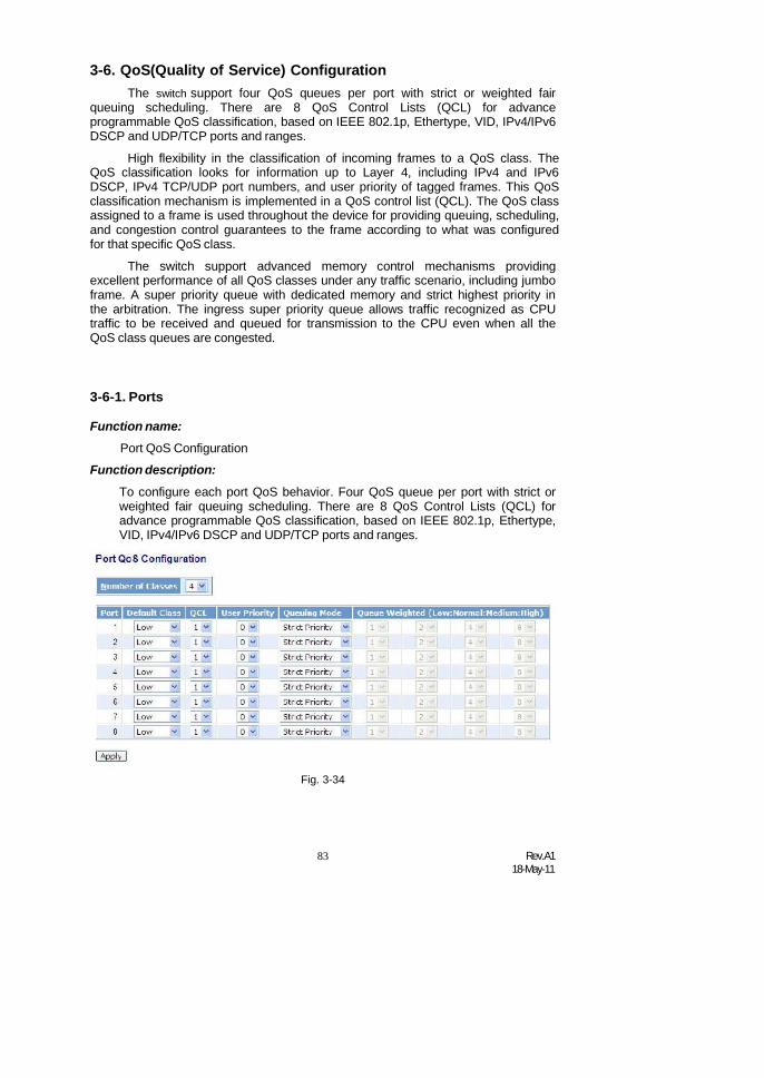
83 Rev.A118-May-11
3-6. QoS(Quality of Service) ConfigurationThe switch support four QoS queues per port with strict or weighted fair
queuing scheduling. There are 8 QoS Control Lists (QCL) for advanceprogrammable QoS classification, based on IEEE 802.1p, Ethertype, VID, IPv4/IPv6DSCP and UDP/TCP ports and ranges.
High flexibility in the classification of incoming frames to a QoS class. TheQoS classification looks for information up to Layer 4, including IPv4 and IPv6DSCP, IPv4 TCP/UDP port numbers, and user priority of tagged frames. This QoSclassification mechanism is implemented in a QoS control list (QCL). The QoS classassigned to a frame is used throughout the device for providing queuing, scheduling,and congestion control guarantees to the frame according to what was configuredfor that specific QoS class.
The switch support advanced memory control mechanisms providingexcellent performance of all QoS classes under any traffic scenario, including jumboframe. A super priority queue with dedicated memory and strict highest priority inthe arbitration. The ingress super priority queue allows traffic recognized as CPUtraffic to be received and queued for transmission to the CPU even when all theQoS class queues are congested.
3-6-1. Ports
Function name:
Port QoS Configuration
Function description:
To configure each port QoS behavior. Four QoS queue per port with strict orweighted fair queuing scheduling. There are 8 QoS Control Lists (QCL) foradvance programmable QoS classification, based on IEEE 802.1p, Ethertype,VID, IPv4/IPv6 DSCP and UDP/TCP ports and ranges.
Fig. 3-34
Rev.A118-May-11
84
Parameter description:
Number of Classes:
1 / 2 / 4
Port:
User can choose the port (1~8) respectively with Priority Class on PerPort Priority function.
Default Class:
User can set up High Priority or Low Priority for each port respectively.
Low / Normal / Medium / High
QCL:
The number of QCL rule 1~8, each port have to apply one of the QCLrule for QoS behavior
User priority:
The user priority value 0~7 (3 bits) is used as an index to the eight QoSclass values for VLAN tagged or priority tagged frames.
Queuing Mode:
There are two Scheduling Method, Strict Priority and Weighted Fair.Default is Strict Priority. After you choose any of Scheduling Method,please click Apply button to be in operation.
Queue Weighted:
There are four queues per port and four classes weighted number (1 / 2 /4 / 8) for each queues, you can select the weighted number when thescheduling method be set to “Weighted Fair” mode.

85 Rev.A118-May-11
3-6-2. Qos Control List
Function name:
Qos Control List Configuration
Function description:
The switch support four QoS queues per port with strict or weighted fairqueuing scheduling. There are 8 QoS Control Lists (QCL) for advanceprogrammable QoS classification, based on IEEE 802.1p, Ether Type, VID,IPv4/IPv6 DSCP and UDP/TCP ports and ranges.
Fig. 3-35
Insert an entry Move up this entry
Delete this entry
Edit this entry
Move down this entry
QCE Configuration:
The QCL consists of 8 QoS Control Entries (QCEs) that are searchedfrom the top of the list to the bottom of the list for a match. The firstmatching QCE determines the QoS classification of the frame. The QCEordering is therefore important for the resulting QoS classificationalgorithm. If no matching QCE is found, the default QoS class is used inthe port QoS configuration.

Rev.A118-May-11
86
Fig. 3-36
Fig. 3-37
Fig. 3-38

87 Rev.A118-May-11
Fig. 3-39
Fig. 3-40
Fig. 3-41
Fig. 3-42

Rev.A118-May-11
88
Parameter description:
QCL#:
QCL number : 1~8
QCE Type:
Ethernet Type / VLAN ID / UDP/TCP Port / DSCP / ToS / Tag Priority
Ethernet Type Value:
The configurable range is 0x600~0xFFFF. Well known protocols alreadyassigned EtherType values. The commonly used values in the EtherTypefield and corresponding protocols are listed below:
Ethertype(Hexadecimal) Protocol
0x0800 IP, Internet Protocol
0x0801 X.75 Internet
0x0802 NBS Internet
0x0803 ECMAInternet
0x0804 Chaosnet
0x0805 X.25 Level 3
0x0806 ARP, Address Resolution Protocol.
0x0808 Frame Relay ARP [RFC1701]
0x6559 Raw Frame Relay [RFC1701]
0x8035 DRARP, Dynamic RARP. RARP, ReverseAddress Resolution Protocol.
0x8037 Novell Netware IPX
0x809B EtherTalk (AppleTalk over Ethernet)
0x80D5 IBM SNA Services over Ethernet
0x 80F3 AARP, AppleTalk Address ResolutionProtocol.
0x8100 IEEE Std 802.1Q - Customer VLAN Tag Type.
0x8137 IPX, Internet Packet Exchange.
0x 814C SNMP, Simple Network ManagementProtocol.
0x86DD IPv6, Internet Protocol version 6.
0x880B PPP, Point-to-Point Protocol.
0x 880C GSMP, General Switch Management

89 Rev.A118-May-11
Protocol.
0x8847 MPLS, Multi-Protocol Label Switching(unicast).
0x8848 MPLS, Multi-Protocol Label Switching(multicast).
0x8863 PPPoE, PPP Over Ethernet (DiscoveryStage).
0x8864 PPPoE, PPP Over Ethernet (PPP SessionStage).
0x88BB LWAPP, Light Weight Access Point Protocol.
0x88CC LLDP, Link Layer Discovery Protocol.
0x8E88 EAPOL, EAP over LAN.
0x9000 Loopback (Configuration Test Protocol)
0xFFFF reserved.
VLAN ID:
The configurable VID range:1~4094
UDP/TCP Port:
To select the UDP/TCP port classification method by Range or Specific.
UDP/TCP Port Range:
The configurable ports range: 0~65535You can refer to following UDP/TCP port-numbers information.http://www.iana.org/assignments/port-numbers
UDP/TCP Port No.:
The configurable specific port value: 0~65535
DSCP Value:
The configurable DSCP value: 0~63
Traffic Class:
Low / Normal / Medium / High

Rev.A118-May-11
90
3-6-3.RateLimiters
Function name:
Rate Limit Configuration
Function description:
Each port includes an ingress policer, and an egress shaper, which can limitthe bandwidth of received and transmitted frames. Ingress policer or egressshaper operation is controlled per port in the Rate Limit Configuration.
Parameter description:
Port #:
Port number.
Policer Enabled:
Fig. 3-43
Policer enabled to limit ingress bandwidth by policer rate.
Policer Rate:
The configurable policer rate range:500 Kbps ~ 1000000 Kbps1 Mbps ~ 1000 Mbps
Policer Unit:
There are two units for ingress policer rate limit: kbps / Mbps
Shaper Enabled:
Shaper enabled to limit egress bandwidth by shaper rate.
Shaper Rate:
The configurable shaper rate range:500 Kbps ~ 1000000 Kbps1 Mbps ~ 1000 Mbps
Shaper Unit:
There are two units for egress shaper rate limit: kbps / Mbps

91 Rev.A118-May-11
3-6-4.StormControl
Function name:
Storm Control Configuration
Function description:
The switch support storm ingress policer control function to limit the Flooded,Multicast and Broadcast to prevent storm event happen.
Fig. 3-44
Parameter description:
Frame Type:
There three frame types of storm can be controlled: Flooded unicast /Multicast / Broadcast
Status:
Enable/Disable Selection: means enabled,
means disabled Rate(pps):
Refer to the following rate configurable value list, the unit is Packet PerSecond (pps).
1 / 2 / 4 / 8 / 16 / 32 / 64 / 128 / 256 / 512 / 1K / 2K / 4K / 8K / 16K / 32K /64K / 128K / 256K / 512K / 1024K

Rev.A118-May-11
92
3-6-5.Wizard
Function name:
Wizard
Function description:
The QCL configuration Wizard is targeted on user can easy to configure theQCL rules for QoS configuration. The wizard provide the typical networkapplication rules, user can apply these application easily.
Parameter description:Fig. 3-45
Please select an Action:
User need to select one of action from following items, then click on<Next> to finish QCL configuration:
Set up Port Policies
Set up Typical Network Application Rules
Set up TOS Precedence Mapping
Set up VLAN Tag Priority Mapping
Next:
Go to next step.
Cancel:
Abort current configuration back to previous step.
Back:
Back to previous screen.
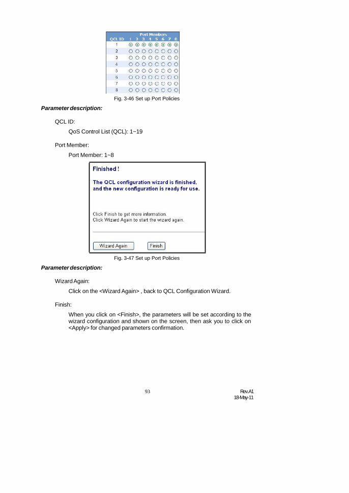
93 Rev.A118-May-11
Parameter description:Fig. 3-46 Set up Port Policies
QCL ID:
QoS Control List (QCL): 1~19
Port Member:
Port Member: 1~8
Parameter description:Fig. 3-47 Set up Port Policies
WizardAgain:
Click on the <Wizard Again> , back to QCL Configuration Wizard.
Finish:
When you click on <Finish>, the parameters will be set according to thewizard configuration and shown on the screen, then ask you to click on<Apply> for changed parameters confirmation.

Rev.A118-May-11
94
Fig. 3-48 Set up Port Policies Finish
Fig. 3-49 Set up Typical Network Application Rules
Fig. 3-50 Set up Typical Network Application Rules

95 Rev.A118-May-11
Fig. 3-51 Set up Typical Network Application Rules
Parameter description:
Audio and Video:
QuickTime 4 Server / MSN Messenger Phone / Yahoo MessengerPhone / Napster / Real Audio
Games:
Blizzard Battlenet (Diablo2 and StarCraft) / Fighter Ace II / Quake2 /Quake3 / MSN Game Zone
User Definition:
Ethernet Type / VLAN ID / UDP/TCP Port / DSCP
Ethernet Type Value:
Type Range: 0x600~0xFFFF
VLAN ID:
VLAN ID Range: 1~4094
UDP/TCP Port:
Two Mode: Range / Specific
UDP/TCP Port Range:
Port Range: 0~65535
UDP/TCP Port No.:
Port Range: 0~65535
DSCP Value:
DSCP Value Range: 0~63
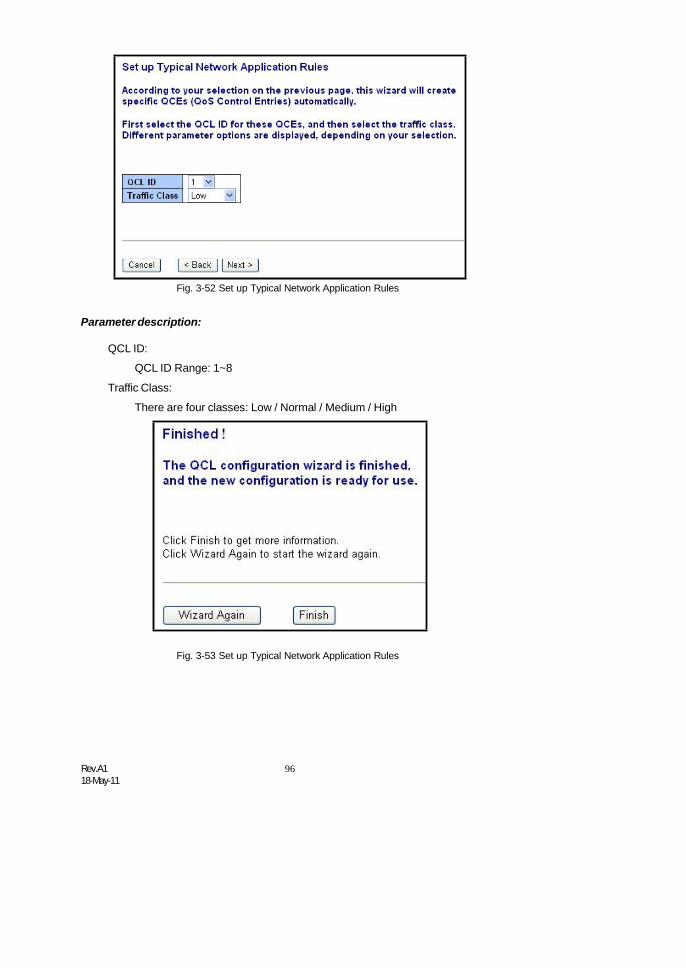
Rev.A118-May-11
96
Fig. 3-52 Set up Typical Network Application Rules
Parameter description:
QCL ID:
QCL ID Range: 1~8
Traffic Class:
There are four classes: Low / Normal / Medium / High
Fig. 3-53 Set up Typical Network Application Rules

97 Rev.A118-May-11
Fig. 3-54 Set up Typical Network Application Rules Finish
Fig. 3-55 Set up Typical Network Application Rules Finish

Rev.A118-May-11
98
Fig. 3-56 Set up Typical Network Application Rules Finish
Parameter description:
QCL #:
QoS Control List (QCL): 1~8
Fig. 3-57 Set up TOS Precedence Mapping
Parameter description:
QCL ID:
QoS Control List (QCL): 1~8
TOS Precedence 0~7 Class:
Low / Normal / Medium / High

99 Rev.A118-May-11
Fig. 3-58 Set up TOS Precedence Mapping
Fig. 3-59 Set up TOS Precedence Mapping Finish
Fig. 3-60 Set up VLAN Tag Priority Mapping
Parameter description:
QCL ID:
QoS Control List (QCL): 1~8
Tag Priority 0~7 Class:
Low / Normal / Medium / High

Rev.A118-May-11
100
Fig. 3-61 Set up VLAN Tag Priority Mapping
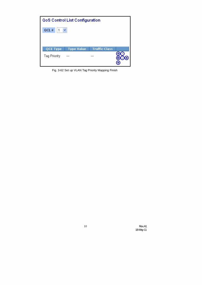
101
Rev.A118-May-11
Fig. 3-62 Set up VLAN Tag Priority Mapping Finish

Rev.A118-May-11
100
3-7. SNMP ConfigurationAny Network Management System (NMS) running the Simple Network
Management Protocol (SNMP) can manage the Managed devices equipped withSNMP agent, provided that the Management Information Base (MIB) is installedcorrectly on the managed devices. The SNMP is a protocol that is used to governthe transfer of information between SNMP manager and agent and traverses theObject Identity (OID) of the management Information Base (MIB), described in theform of SMI syntax. SNMP agent is running on the switch to response the requestissued by SNMP manager.
Basically, it is passive except issuing the trap information. The switchsupports a switch to turn on or off the SNMP agent. If you set the field SNMP“Enable”, SNMP agent will be started up. All supported MIB OIDs, including RMONMIB, can be accessed via SNMP manager. If the field SNMP is set “Disable”, SNMPagent will be de-activated, the related Community Name, Trap Host IP Address,Trap and all MIB counters will be ignored.
Function name:
SNMP System Configuration
Function description:
This function is used to configure SNMP settings, community name, trap hostand public traps as well as the throttle of SNMP. A SNMP manager must pass theauthentication by identifying both community names, then it can access the MIBinformation of the target device. So, both parties must have the same communityname. Once completing the setting, click <Apply> button, the setting takes effect.
Fig. 3-63 SNMP System setting
Parameters description:
SNMP State:
The term SNMP here The term SNMP here is used for the activation orde-activation of SNMP.
Enable: Enable SNMP state operation.
Disable: Disable SNMP state operation.
Default: Enable.
Engine ID:
SNMPv3 engine ID. syntax: 0-9,a-f,A-F, min 5 octet, max 32 octet, fifthoctet can't input 00. IF change the Engine ID that will clear all originaluser.
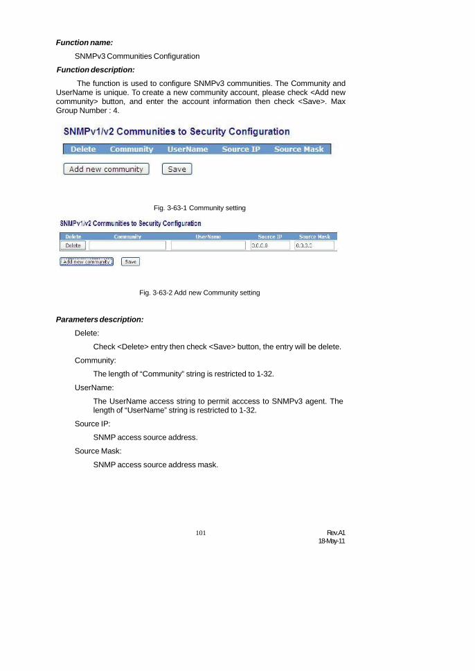
101 Rev.A118-May-11
Function name:
SNMPv3 Communities Configuration
Function description:
The function is used to configure SNMPv3 communities. The Community andUserName is unique. To create a new community account, please check <Add newcommunity> button, and enter the account information then check <Save>. MaxGroup Number : 4.
Fig. 3-63-1 Community setting
Fig. 3-63-2 Add new Community setting
Parameters description:
Delete:
Check <Delete> entry then check <Save> button, the entry will be delete.
Community:
The length of “Community” string is restricted to 1-32.
UserName:
The UserName access string to permit acccess to SNMPv3 agent. Thelength of “UserName” string is restricted to 1-32.
Source IP:
SNMP access source address.
Source Mask:
SNMP access source address mask.

Rev.A118-May-11
102
Function name:SNMPv3 Users Configuration
Function description:
The function is used to configure SNMPv3 user. The Entry index key isUserName. To create a new UserName account, please check <Add new user>button, and enter the user information then check <Save>. Max Group Number : 10.
Parameters description:
Delete:
Fig. 3-63-3 Add new user setting
Check <Delete> entry then check <Save> button, the entry will be delete.
UserName:
The length of “UserName” string is restricted to 1-32.Security Level:
There are three kinds of choices:
NoAuth, NoPriv: No authentication and no privacy.
Auth, NoPriv: Authentication and no privacy.
Auth, Priv: Authentication and privacy.
Authentication Protocol:
You can choose MD5 or SHA for authentication.
AuthenticationPassword:
The length of 'MD5 Authentication Password' is restricted to 8 – 32.
The length of 'SHAAuthentication Password' is restricted to 8 – 40.
Privacy Protocol:
You can set DES encryption for UserName.
Privacy Password:
The length of ' Privacy Password ' is restricted to 8 – 32.

103 Rev.A118-May-11
Function name:SNMPv3 Groups Configuration
Function description:
The function is used to configure SNMPv3 group. The Entry index key areSecurity Model and Security Name. To create a new group account, please check<Add new group> button, and enter the group information then check <Save>. MaxGroup Number : v1: 2, v2: 2, v3:10.
Fig. 3-63-4 Add new group setting
Parameters description:
Delete:
Fig. 3-63-5 Add new group setting
Check <Delete> entry then check <Save> button, the entry will be delete.
Security Model:
There are three kinds of choices.
v1: SNMPv1.
v2c: SNMPv2c.
usm: User-based Security Model.The length of “UserName” string isrestricted to 1-32.
Security Name:
The length of “Security Name” string is restricted to 1-32.
Group Name:
The length of “Group Name” string is restricted to 1-32.

Rev.A118-May-11
104
Function name:SNMPv3 Views Configuration
Function description:
The function is used to configure SNMPv3 view. The Entry index key are OIDSubtree and View Name. To create a new view account, please check <Add newview> button, and enter the view information then check <Save>. Max GroupNumber : 28.
Fig. 3-63-6 Add new SNMPv3 views setting
Parameters description:
Delete:
Check <Delete> entry then check <Save> button, the entry will be delete.
View Name:
The name of MIB view. The length of “View Name” string is restricted to1-32.
View Type:
The access type for the view subtree: included or excluded.
OID Subtree:
The OID defining the root of the subtree to add to the named view.

105 Rev.A118-May-11
Function name:SNMPv3 Accesses Configuration
Function description:
The function is used to configure SNMPv3 accesses. The Entry index key areGroup Name, Security Model and Security level. To create a new access account,please check <Add new access> button, and enter the access information thencheck <Save>. Max Group Number : 14.
Fig. 3-63-7 Add new SNMPv3 Accesses setting
Parameters description:
Delete:
Check <Delete> entry then check <Save> button, the entry will be delete.
Group Name:
The length of “Group Name” string is restricted to 1-32.
Security Model:
There are four kinds of choices.
any: Accepted any security model(v1|v2c|usm).
v1: SNMPv1.
v2c: SNMPv2c.
usm: User-based Security Model.
Security Level:
There are three kinds of choices.
NoAuth, NoPriv: No authentication and no privacy.
Auth, NoPriv: Authentication and no privacy.
Auth, Priv: Authentication and privacy.
Read View Name:
The name of MIB view. Select “None”, this entry has no read right.
Write View Name:
The name of MIB view. Select “None”, this entry has no write right.

Rev.A118-May-11
106
Function name:Trap Hosts Configuration
Function description:
The function is used to configure SNMP trap. To create a new trap account,please check <No number> button, and enter the trap information then check<Apply>. Max Group Number : 6.
Fig. 3-63-8 The Trap Hosts setting
Parameters description:
Delete:
Fig. 3-63-9 The Trap Hosts setting
Check <Delete> entry then check <Save> button, the entry will be delete.
Version:
You may choose v1, v2c or v3 trap.
IP:
SNMP Host IP address.

107 Rev.A118-May-11
Port:
Port number. Default: 162
Community / Security Name:
The length of “Community / Security Name” string is restricted to 1-32.
Security Level:
There are three kinds of choices.
NoAuth, NoPriv: No authentication and no privacy.
Auth, NoPriv: Authentication and no privacy.
Auth, Priv: Authentication and privacy.
Authentication Protocol:
You can choose MD5 or SHA for authentication.
AuthenticationPassword:
The length of 'MD5 Authentication Password' is restricted to 8 – 32.
The length of 'SHAAuthentication Password' is restricted to 8 – 40.
Privacy Protocol:
You can set DES encryption for UserName.
Privacy Password:
The length of ' Privacy Password ' is restricted to 8 – 32.
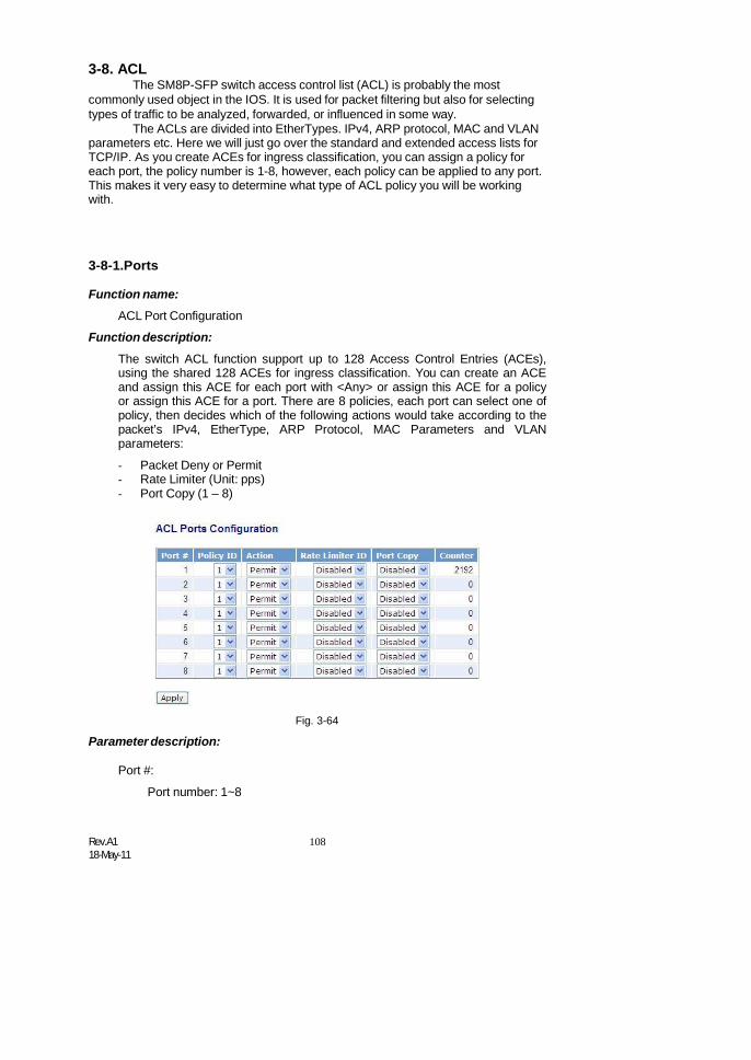
Rev.A118-May-11
108
3-8. ACLThe SM8P-SFP switch access control list (ACL) is probably the most
commonly used object in the IOS. It is used for packet filtering but also for selectingtypes of traffic to be analyzed, forwarded, or influenced in some way.
The ACLs are divided into EtherTypes. IPv4, ARP protocol, MAC and VLANparameters etc. Here we will just go over the standard and extended access lists forTCP/IP. As you create ACEs for ingress classification, you can assign a policy foreach port, the policy number is 1-8, however, each policy can be applied to any port.This makes it very easy to determine what type of ACL policy you will be workingwith.
3-8-1.Ports
Function name:
ACL Port Configuration
Function description:
The switch ACL function support up to 128 Access Control Entries (ACEs),using the shared 128 ACEs for ingress classification. You can create an ACEand assign this ACE for each port with <Any> or assign this ACE for a policyor assign this ACE for a port. There are 8 policies, each port can select one ofpolicy, then decides which of the following actions would take according to thepacket’s IPv4, EtherType, ARP Protocol, MAC Parameters and VLANparameters:
- Packet Deny or Permit- Rate Limiter (Unit: pps)- Port Copy (1 – 8)
Parameter description:
Port #:
Port number: 1~8
Fig. 3-64

109 Rev.A118-May-11
Policy ID:
Policy ID range:1~8
Action:
Permit or Deny forwarding the met ACL packets
Rate Limiter ID:
Disabled: Disable Rate Limitation
Rate Limiter ID Range: 1~16. To select one of rate limiter ID for this port,it will limit met ACL packets by rate limiter ID configuration.
Port Copy:
Disabled: Disable to copy the met ACL packets to specific port
Port number: 1~8. Copy the met ACL packets to the selected port
Counter:
The counter will increase from initial value 0, when this port received oneof the met ACL packet the counter value will increase +1

Rev.A118-May-11
110
3-8-2.RateLimiters
Function name:
ACL Rate Limiter Configuration
Function description:
There are 16 rate limiter ID. You can assign one of the limiter ID for each port.The rate limit configuration unit is Packet Per Second (pps).
Fig. 3-65
Parameter description:
Rate Limiter ID:
ID Range: 1~16
Rate(pps):
1 / 2 / 4 / 8 / 16 / 32 / 64 / 128 / 256 / 512 / 1K / 2K / 4K / 8K / 16K / 32K /64K / 128K / 256K / 512K / 1024K

111 Rev.A118-May-11
3-8-3.Access Control List
Function name:
ACL Rate Limiter Configuration
Function description:
The switch ACL function support up to 128 Access Control Entries (ACEs),using the shared 128 ACEs for ingress classification. You can create an ACEand assign this ACE for each port with <Any> or assign this ACE for a policyor assign this ACE for a port. There are 8 policies, each port can select one ofpolicy, then decides which of the Permit/Deny, Rate Limitation and Port Copyactions would take according to the ACL configuration packet’s IPv4,EtherType, ARP Protocol, MAC Parameters and VLAN parameters.
Fig. 3-66 Ingress Port
Insert an entry
Edit this entry
Move up this entry
Move down this entry
Parameter description:
Ingress Port:
Configurable Range: Any / Policy 1-8 / Port 1-8Any: Apply this ACE rule for each port ingress classificationPolicy 1-8: Apply this ACE rule for specific policyPort 1-8: Apply this ACE rule for specific port ingress classification

Rev.A118-May-11
112
Fig. 3-67 Ingress Port
Fig. 3-68
Parameter description:
Frame Type:
Range: Any / Ethernet Type / ARP / IPv4Any: It is including all frame typeEthernet Type: It is including all Ethernet frame typeARP: It is including all ARP protocol frame typeIPv4: It is including all IPv4 protocol frame type

113 Rev.A118-May-11
Fig. 3-69 Frame Type
Fig. 3-70

Rev.A118-May-11
114
Fig. 3-71
Fig. 3-72
Fig. 3-73 ARP
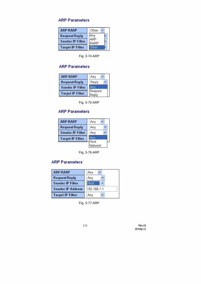
115 Rev.A118-May-11
Fig. 3-74 ARP
Fig. 3-75 ARP
Fig. 3-76 ARP
Fig. 3-77 ARP
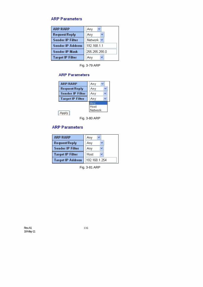
Rev.A118-May-11
116
Fig. 3-79 ARP
Fig. 3-80 ARP
Fig. 3-81 ARP

117 Rev.A118-May-11
Fig. 3-82 ARP
Fig. 3-83 ARP
Fig. 3-84 ARP
Fig. 3-85 ARP
Fig. 3-86 ARP

Rev.A118-May-11
118
Fig. 3-87 ARP
Fig. 3-88 IPv4

119 Rev.A118-May-11
Fig. 3-89 IPv4
Fig. 3-90 IPv4
Fig. 3-91 IPv4
Fig. 3-92 IPv4
Fig. 3-93 IPv4

Rev.A118-May-11
120
Fig. 3-94 IPv4
Fig. 3-95 IPv4
Fig. 3-96 IPv4
Fig. 3-97 IPv4
Fig. 3-98 IPv4
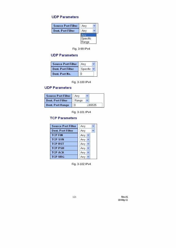
121 Rev.A118-May-11
Fig. 3-99 IPv4
Fig. 3-100 IPv4
Fig. 3-101 IPv4
Fig. 3-102 IPv4

Rev.A118-May-11
122
Fig. 3-103 IPv4
Fig. 3-104 IPv4
Fig. 3-105 IPv4

123 Rev.A118-May-11
Fig. 3-106 IPv4
Fig. 3-107 IPv4
Fig. 3-108 IPv4

Rev.A118-May-11
124
Fig. 3-109 IPv4
Fig. 3-110 IPv4
Fig. 3-111 IPv4

125 Rev.A118-May-11
Fig. 3-112 IPv4
Fig. 3-113 IPv4
Fig. 3-114 IPv4

Rev.A118-May-11
126
Fig. 3-115 IPv4
Fig. 3-116 IPv4
Fig. 3-117 IPv4

127 Rev.A118-May-11
Fig. 3-118 Action
Fig. 3-119 Rate Limiter

Rev.A118-May-11
128
Fig. 3-120 Port Copy
Fig. 3-121 DMAC Filter

129 Rev.A118-May-11
Fig. 3-122 VLAN ID Filter
Fig. 3-123 VLAN ID Filter
Fig. 3-124 Tag Priority

Rev.A118-May-11
130
Function name:
ACE Configuration
Function description:
The switch ACL function support up to 128 Access Control Entries (ACEs),using the shared 128 ACEs for ingress classification. You can create an ACEand assign this ACE for each port with <Any> or assign this ACE for a policyor assign this ACE for a port. There are 8 policies, each port can select one ofpolicy, then decides which of the Permit/Deny, Rate Limitation and Port Copyactions would take according to the ACL configuration packet’s IPv4,EtherType, ARP Protocol, MAC Parameters and VLAN parameters.
Parameter description:
Ingress Port:
Range: Any / Policy 1-8 / Port 1-8Any: Apply this ACE rule for each port ingress classificationPolicy 1-8: Apply this ACE rule for specific policyPort 1-24: Apply this ACE rule for specific port ingress classification
IP Protocol Filter:
Range: Any / Ethernet Type / ARP / IPv4Any: It is including all frame typeEthernet Type: It is including all Ethernet frame typeARP: It is including all ARP protocol frame typeIPv4: It is including all IPv4 protocol frame type
MAC Parameters: (When Frame Type = Any)
DMAC Filter:
Range: Any / MC / BC / UC
Any: It is including all destination MAC addressMC: It is including all Multicast MAC addressBC: It is including all Broadcast MAC addressUC: It is including all Unicast MAC address
MAC Parameters: (When Frame Type = Ethernet Type)
SMAC Filter:
Range: Any / Specific
Any: It is including all source MAC addressSpecific: It is according to SMAC Value specific the source MACaddress
DMAC Filter:
Range: Any / MC / BC / UC / Specific
Any: It is including all destination MAC addressMC: It is including all Multicast MAC addressBC: It is including all Broadcast MAC addressUC: It is including all Unicast MAC addressSpecific: It is according to DMAC Value specific the destinationMAC address
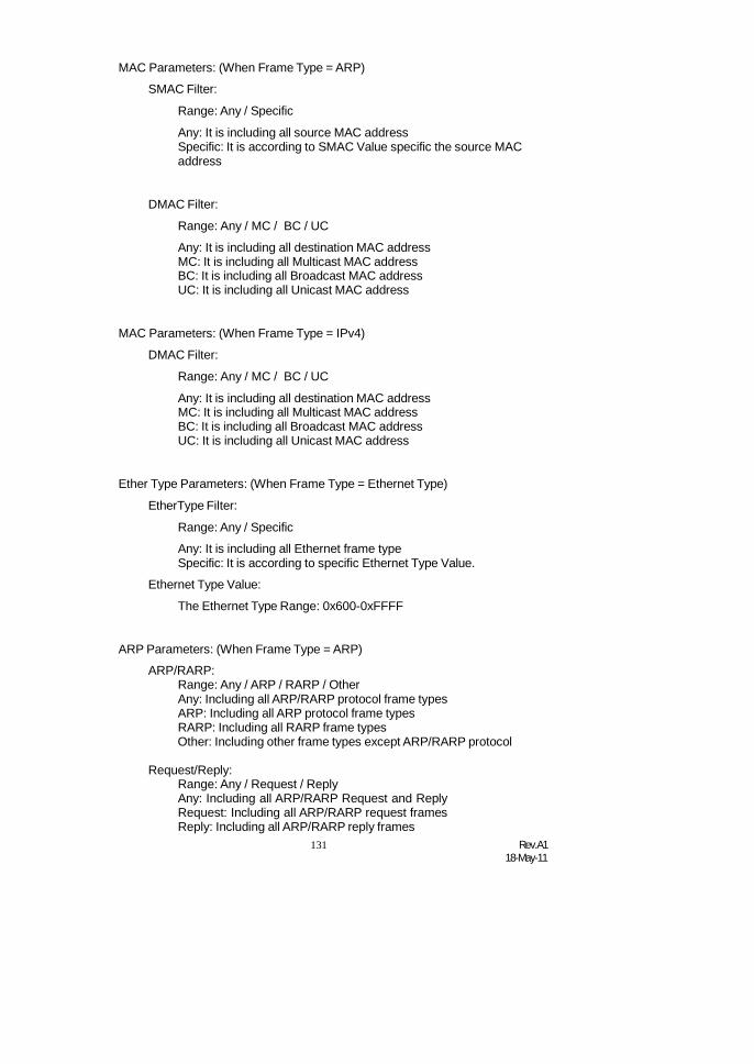
131 Rev.A118-May-11
MAC Parameters: (When Frame Type = ARP)
SMAC Filter:
Range: Any / Specific
Any: It is including all source MAC addressSpecific: It is according to SMAC Value specific the source MACaddress
DMAC Filter:
Range: Any / MC / BC / UC
Any: It is including all destination MAC addressMC: It is including all Multicast MAC addressBC: It is including all Broadcast MAC addressUC: It is including all Unicast MAC address
MAC Parameters: (When Frame Type = IPv4)
DMAC Filter:
Range: Any / MC / BC / UC
Any: It is including all destination MAC addressMC: It is including all Multicast MAC addressBC: It is including all Broadcast MAC addressUC: It is including all Unicast MAC address
Ether Type Parameters: (When Frame Type = Ethernet Type)
EtherType Filter:
Range: Any / Specific
Any: It is including all Ethernet frame typeSpecific: It is according to specific Ethernet Type Value.
Ethernet Type Value:
The Ethernet Type Range: 0x600-0xFFFF
ARP Parameters: (When Frame Type = ARP)
ARP/RARP:Range: Any / ARP / RARP / OtherAny: Including all ARP/RARP protocol frame typesARP: Including all ARP protocol frame typesRARP: Including all RARP frame typesOther: Including other frame types except ARP/RARP protocol
Request/Reply:Range: Any / Request / ReplyAny: Including all ARP/RARP Request and ReplyRequest: Including all ARP/RARP request framesReply: Including all ARP/RARP reply frames

Rev.A118-May-11
132
Sender IP Filter:Range: Any / Host / NetworkAny: Including all sender IP addressHost: Only one specific sender host IP addressNetwork: A specific IP subnet segment under the sender IP mask
Sender IP Address:Default: 192.168.1.77
Sender IP Mask:Default: 255.255.255.0
Target IP Filter:Range: Any / Host / NetworkAny: Including all target IP addressHost: Only one specific target host IP addressNetwork: A specific IP subnet segment under the target IP mask
Target IP Address:Default: 192.168.1.254
Target IP Mask:Default: 255.255.255.0
ARP SMAC Match:Range: Any / 0 / 1Any:
Both 0 and 10:
The ingress ARP frames where the source MAC address isnot equal SMAC under MAC parameter setting
1:The ingress ARP frames where the source MAC address isequal SMAC address under MAC parameter setting
RARP DMAC Match:Range: Any / 0 / 1Any:
Both 0 and 10:
The ingress RARP frames where the Destination MACaddress is not equal DMAC address under MAC parametersetting
1:The ingress RARP frames where the Destination MACaddress is equal DMAC address under MAC parametersetting
IP/Ethernet Length:Range: Any / 0 / 1Any:
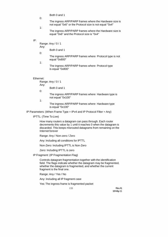
133 Rev.A118-May-11
Both 0 and 10:
The ingress ARP/PARP frames where the Hardware size isnot equal "0x6" or the Protocol size is not equal "0x4"
1:The ingress ARP/PARP frames where the Hardware size isequal "0x6" and the Protocol size is "0x4"
IP:Range: Any / 0 / 1Any:
Both 0 and 10:
The ingress ARP/PARP frames where Protocol type is notequal "0x800"
1:The ingress ARP/PARP frames where Protocol typeis equal "0x800"
Ethernet:Range: Any / 0 / 1Any:
Both 0 and 10:
The ingress ARP/PARP frames where Hardware type isnot equal "0x100"
1:The ingress ARP/PARP frames where Hardware typeis equal "0x100"
IP Parameters: (When Frame Type = IPv4 and IP Protocol Filter = Any)
IPTTL: (Time To Live)
How many routers a datagram can pass through. Each routerdecrements this value by 1 until it reaches 0 when the datagram isdiscarded. This keeps misrouted datagrams from remaining on theInternet forever
Range: Any / Non-zero / Zero
Any: Including all conditions for IPTTL
Non-Zero: Including IPTTL is Non-Zero
Zero: Including IPTTL is zero
IP Fragment: (IP Fragmentation Flag)
Controls datagram fragmentation together with the identificationfield. The flags indicate whether the datagram may be fragmented,whether the datagram is fragmented, and whether the currentfragment is the final one.
Range: Any / Yes / No
Any: Including all IP fragment case
Yes: The ingress frame is fragmented packet

Rev.A118-May-11
134
No: The ingress frames is not fragmented packet
IP Option:
A list of optional specifications for security restrictions, routerecording, and source routing. Not every datagram specifies anoptions field.
Range: Any / Yes / No
Any: Including all IP option caseYes: The ingress frame is specified IP optionsNo: The ingress frame is not specified IP options
SIP Filter: (SIP Source IP Address)
Range: Any / Host / Network
Any: Including all source IP addressHost: Only one specific source host IP addressNetwork: A specific IP subnet segment under the source IP mask
SIPAddress:
Default: 192.168.1.77
SIP Mask:
Default: 255.255.255.0
DIP Filter: (DIP Destination IP Address)
Range: Any / Host / Network
Any: Including all destination IP addressHost: Only one specific destination host IP addressNetwork: A specific IP subnet segment under the destination IPmask
DIPAddress:
Default: 192.168.1.254
DIP Mask:
Default: 255.255.255.0
IP Parameters: (Frame Type = IPv4 and IP Protocol Filter = ICMP)
ICMP Type Filter:
Range: Any / Specific
Any: Including all types of ICMP type values
Specific: According to following ICMP type value setting for ingressclassification
ICMP Type Value:
Range: 0-255
ICMP Code Filter:
Range: Any / Specific
Any: Including all of ICMP code values
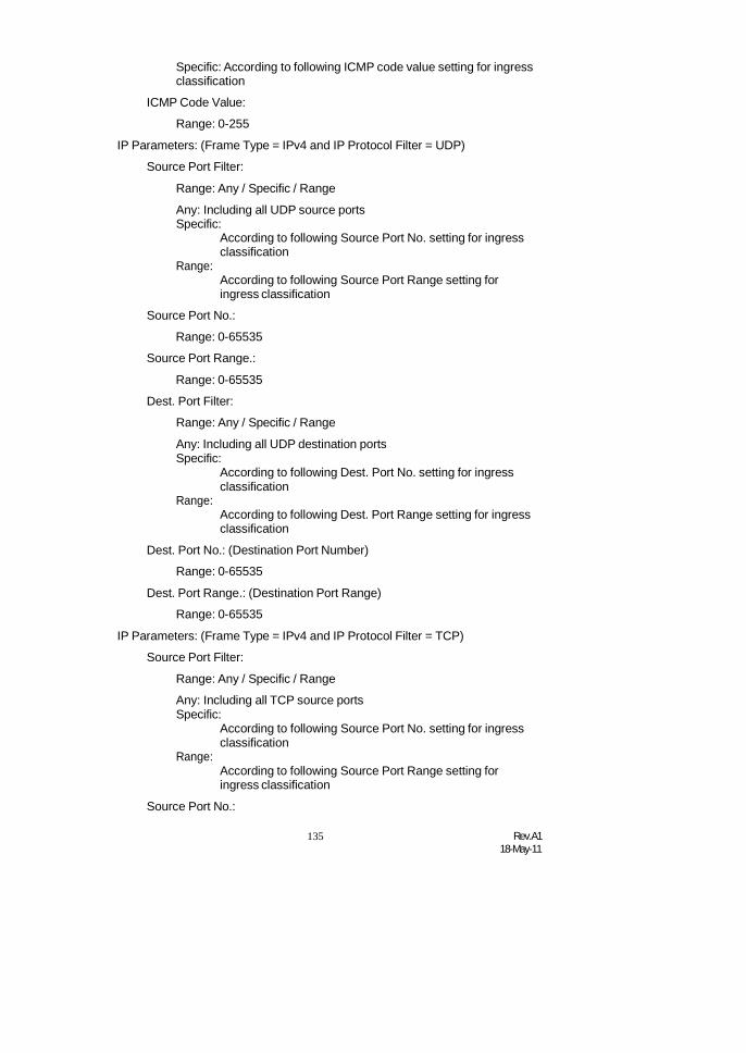
135 Rev.A118-May-11
Specific: According to following ICMP code value setting for ingressclassification
ICMP Code Value:
Range: 0-255
IP Parameters: (Frame Type = IPv4 and IP Protocol Filter = UDP)
Source Port Filter:
Range: Any / Specific / Range
Any: Including all UDP source portsSpecific:
According to following Source Port No. setting for ingressclassification
Range:According to following Source Port Range setting foringress classification
Source Port No.:
Range: 0-65535
Source Port Range.:
Range: 0-65535
Dest. Port Filter:
Range: Any / Specific / Range
Any: Including all UDP destination portsSpecific:
According to following Dest. Port No. setting for ingressclassification
Range:According to following Dest. Port Range setting for ingressclassification
Dest. Port No.: (Destination Port Number)
Range: 0-65535
Dest. Port Range.: (Destination Port Range)
Range: 0-65535
IP Parameters: (Frame Type = IPv4 and IP Protocol Filter = TCP)
Source Port Filter:
Range: Any / Specific / Range
Any: Including all TCP source portsSpecific:
According to following Source Port No. setting for ingressclassification
Range:According to following Source Port Range setting foringress classification
Source Port No.:

Rev.A118-May-11
136
Range: 0-65535
Source Port Range.:
Range: 0-65535
Dest. Port Filter:
Range: Any / Specific / Range
Any: Including all TCP destination portsSpecific:
According to following Dest. Port No. setting for ingressclassification
Range:According to following Dest. Port Range setting for ingressclassification
Dest. Port No.:
Range: 0-65535
Dest. Port Range.:
Range: 0-65535
TCP FIN:
TCP Control Bit FIN: Means No more data from sender
Range: Any / 0 / 1
Any: Including all TCP FIN case
0: The TCP control bit FIN is 0
1: The TCP control bit FIN is 1
TCP SYN:
TCP Control Bit SYN: Means Synchronize sequence numbers
Range: Any / 0 / 1
Any: Including all TCP SYN case
0: The TCP control bit SYN is 0
1: The TCP control bit SYN is 1
TCP RST:
TCP Control Bit RST: Means Reset the connection
Range: Any / 0 / 1
Any: Including all TCP RST case
0: The TCP control bit RST is 0
1: The TCP control bit RST is 1
TCP PSH:
TCP Control Bit PSH: Means Push Function
Range: Any / 0 / 1
Any: Including all TCP PSH case

137 Rev.A118-May-11
0: The TCP control bit PSH is 0
1: The TCP control bit PSH is 1
TCP ACK:
TCP Control Bit ACK: Means Acknowledgment field significant
Range: Any / 0 / 1
Any: Including all TCP ACK case
0: The TCP control bit ACK is 0
1: The TCP control bit ACK is 1
TCP URG:
TCP Control Bit URG: Means Urgent Pointer field significant
Range: Any / 0 / 1
Any: Including all TCP URG case
0: The TCP control bit URG is 0
1: The TCP control bit URG is 1
IP Protocol Value:
The IP Protocol Value is TCP options may occupy space at the endof the TCP header and are a multiple of 8 bits in length. Currentlydefined options include (kind indicated in octal):0 - End of option list1 - No-Operation
Range: Any / 0 / 1
Any: Including all IP protocol value case
0: The IP protocol value is 0
1: The IP protocol value is 1
IP Parameters: (Frame Type = IPv4 and IP Protocol Filter = Other)
IP Protocol Value
Default: 255
IPTTL: (Time To Live)
How many routers a datagram can pass through. Each routerdecrements this value by 1 until it reaches 0 when the datagram isdiscarded. This keeps misrouted datagrams from remaining on theInternet forever
Range: Any / Non-zero / Zero
Any: Including all conditions for IPTTL
Non-Zero: Including IPTTL is Non-Zero
Zero: Including IPTTL is zero
IP Fragment: (IP Fragmentation Flag)

Rev.A118-May-11
138
Controls datagram fragmentation together with the identificationfield. The flags indicate whether the datagram may be fragmented,whether the datagram is fragmented, and whether the currentfragment is the final one.
Range: Any / Yes / No
Any: Including all IP fragment case
Yes: The ingress frame is fragmented packet
No: The ingress frames is not fragmented packet
IP Option:
A list of optional specifications for security restrictions, routerecording, and source routing. Not every datagram specifies anoptions field.
Range: Any / Yes / No
Any: Including all IP option caseYes: The ingress frame is specified IP optionsNo: The ingress frame is not specified IP options
SIP Filter: (SIP Source IP Address)
Range: Any / Host / Network
Any: Including all source IP addressHost: Only one specific source host IP addressNetwork: A specific IP subnet segment under the source IP mask
SIPAddress:
Default: 192.168.1.77
SIP Mask:
Default: 255.255.255.0
DIP Filter: (DIP Destination IP Address)
Range: Any / Host / Network
Any: Including all destination IP addressHost: Only one specific destination host IP addressNetwork: A specific IP subnet segment under the destination IPmask
DIPAddress:
Default: 192.168.1.254
DIP Mask:
Default: 255.255.255.0
VLAN Parameters:
VLAN ID Filter:
Range: Any / SpecificAny: Including all VLAN IDsSpecific: According to following VLAN ID and Tag Priority setting for
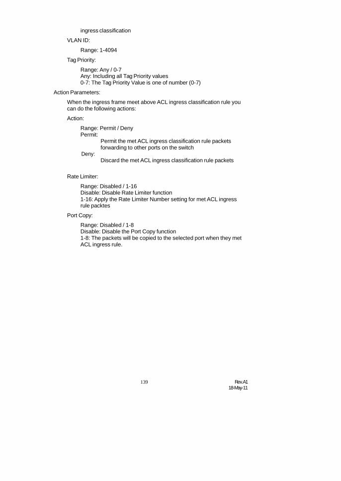
139 Rev.A118-May-11
ingress classification
VLAN ID:
Range: 1-4094
Tag Priority:
Range: Any / 0-7Any: Including all Tag Priority values0-7: The Tag Priority Value is one of number (0-7)
Action Parameters:
When the ingress frame meet above ACL ingress classification rule youcan do the following actions:
Action:
Range: Permit / DenyPermit:
Deny:
Permit the met ACL ingress classification rule packetsforwarding to other ports on the switch
Discard the met ACL ingress classification rule packets
Rate Limiter:
Range: Disabled / 1-16Disable: Disable Rate Limiter function1-16: Apply the Rate Limiter Number setting for met ACL ingressrule packtes
Port Copy:
Range: Disabled / 1-8Disable: Disable the Port Copy function1-8: The packets will be copied to the selected port when they metACL ingress rule.
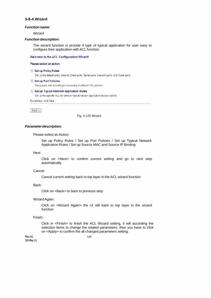
Rev.A118-May-11
140
3-8-4.Wizard
Function name:
Wizard
Function description:
The wizard function is provide 4 type of typical application for user easy toconfigure their application with ACL function.
Fig. 3-125 Wizard
Parameter description:
Please select an Action:
Set up Policy Rules / Set up Port Policies / Set up Typical NetworkApplication Rules / Set up Source MAC and Source IP Binding
Next:
Click on <Next> to confirm current setting and go to next stepautomatically.
Cancel:
Cancel current setting back to top layer in the ACL wizard function
Back:
Click on <Back> to back to previous step
WizardAgain:
Click on <Wizard Again> the UI will back to top layer in the wizardfunction
Finish:
Click in <Finish> to finish the ACL Wizard setting, it will according theselection items to change the related parameters, then you have to clickon <Apply> to confirm the all changed parameters setting.
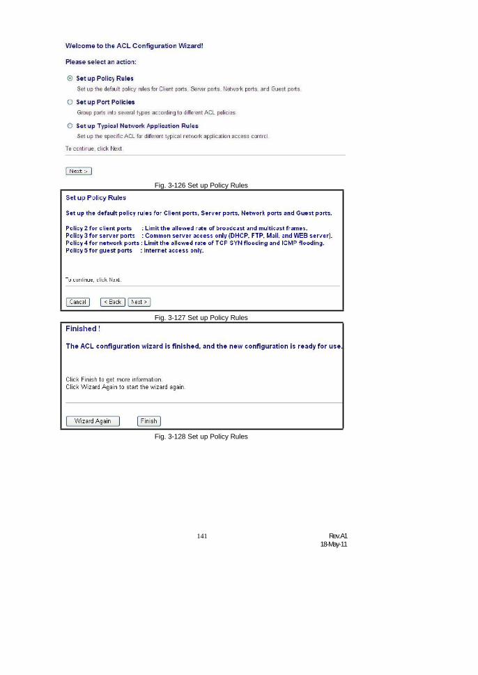
141 Rev.A118-May-11
Fig. 3-126 Set up Policy Rules
Fig. 3-127 Set up Policy Rules
Fig. 3-128 Set up Policy Rules
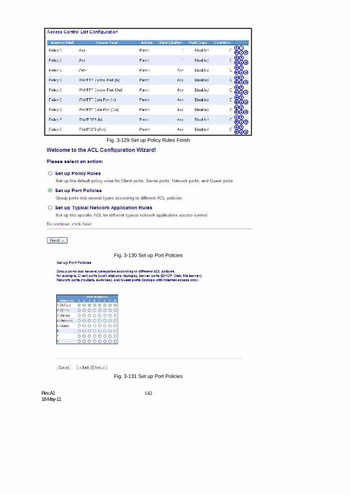
Rev.A118-May-11
142
Fig. 3-129 Set up Policy Rules Finish
Fig. 3-130 Set up Port Policies
Fig. 3-131 Set up Port Policies

143 Rev.A118-May-11
Fig. 3-132 Set up Port Policies
Fig. 3-133 Set up Port Policies Finish
Fig. 3-134 Set up Typical Network Application Rules

Rev.A118-May-11
144
Fig. 3-135 Set up Typical Network Application Rules
Fig. 3-136 Set up Typical Network Application Rules
Fig. 3-137 Set up Typical Network Application Rules
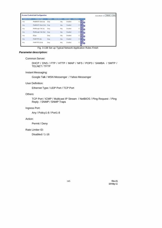
145 Rev.A118-May-11
Fig. 3-138 Set up Typical Network Application Rules Finish
Parameter description:
Common Server:
DHCP / DNS / FTP / HTTP / IMAP / NFS / POP3 / SAMBA / SMTP /TELNET / TFTP
Instant Messaging:
Google Talk / MSN Messenger / Yahoo Messenger
User Definition:
Ethernet Type / UDP Port / TCP Port
Others:
TCP Port / ICMP / Multicast IP Stream / NetBIOS / Ping Request / PingReply / SNMP / SNMP Traps
Ingress Port:
Any / Policy1-8 / Port1-8
Action:
Permit / Deny
Rate Limiter ID:
Disabled / 1-16

Rev.A118-May-11
146
3-9. IP MAC BindingThe IP network layer uses a four-byte address. The Ethernet link layer uses
a six-byte MAC address. Binding these two address types together allows thetransmission of data between the layers. The primary purpose of IP-MAC binding isto restrict the access to a switch to a number of authorized users. Only theauthorized client can access the Switch’s port by checking the pair of IP-MACAddresses and port number with the pre-configured database. If an unauthorizeduser tries to access an IP-MAC binding enabled port, the system will block theaccess by dropping its packet.
Function name:
IP MAC Binding Configuration
Function description:
The switch has IP-MAC Binding table. The maximum number of IP-MACbinding table is 1024 entries. The creation of authorized users can be manually. Thefunction is global, this means a user can enable or disable the function for all portson the switch.
Fig. 3-143
Parameters description:
State:
Disabled / Enabled
Time Interval:
Range: 10 / 20 / 30
Time interval is for ARP echo, the switch will according to server tableentries to send ARP echo.
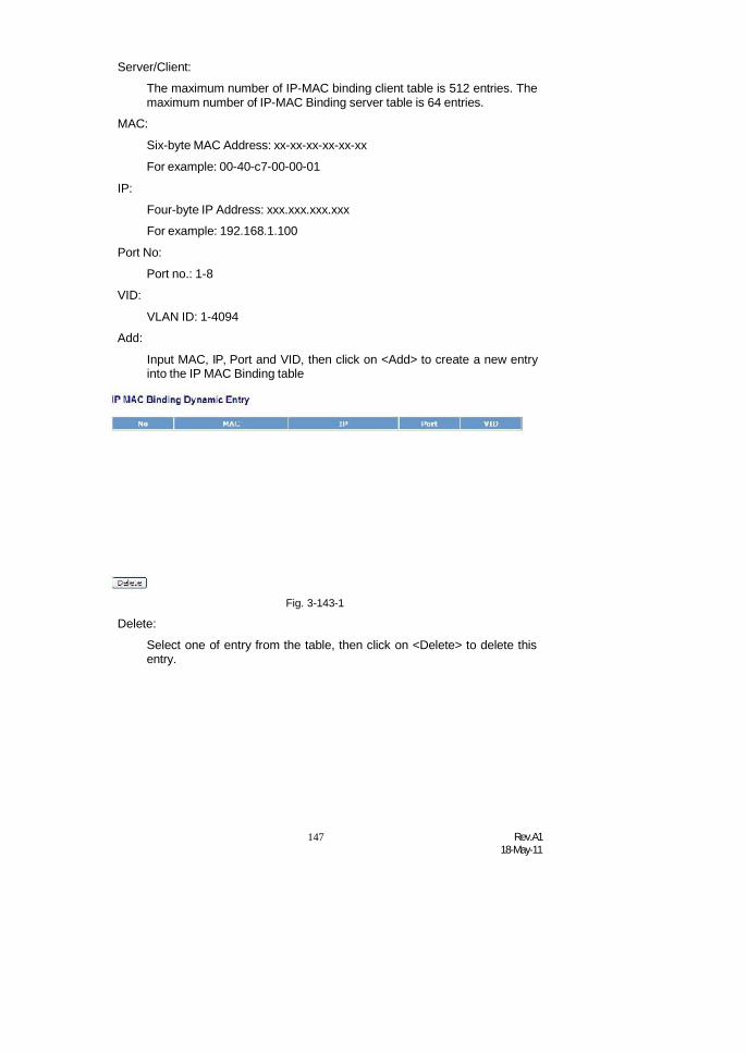
147 Rev.A118-May-11
Server/Client:
The maximum number of IP-MAC binding client table is 512 entries. Themaximum number of IP-MAC Binding server table is 64 entries.
MAC:
Six-byte MAC Address: xx-xx-xx-xx-xx-xx
For example: 00-40-c7-00-00-01
IP:
Four-byte IP Address: xxx.xxx.xxx.xxx
For example: 192.168.1.100
Port No:
Port no.: 1-8
VID:
Add:
VLAN ID: 1-4094
Input MAC, IP, Port and VID, then click on <Add> to create a new entryinto the IP MAC Binding table
Delete:
Fig. 3-143-1
Select one of entry from the table, then click on <Delete> to delete thisentry.

Rev.A118-May-11
148
3-10. 802.1X Configuration802.1port-based network access control provides a method to restrict
users to access network resources via authenticating user’s information. Thisrestricts users from gaining access to the network resources through a 802.1X-enabled port without authentication. If a user wishes to touch the network through aport under 802.1X control, he (she) must firstly input his (her) account name forauthentication and waits for gaining authorization before sending or receiving anypackets from a 802.1X-enabled port.
Before the devices or end stations can access the network resources throughthe ports under 802.1X control, the devices or end stations connected to acontrolled port send the authentication request to the authenticator, theauthenticator pass the request to the authentication server to authenticate and verify,and the server tell the authenticator if the request get the grant of authorization forthe ports.
According to IEEE802.1X, there are three components implemented. Theyare Authenticator, Supplicant and Authentication server shown in Fig. 3-53.
Supplicant:
It is an entity being authenticated by an authenticator. It is used tocommunicate with the Authenticator PAE (Port Access Entity) byexchanging the authentication message when the Authenticator PAErequest to it.
Authenticator:
An entity facilitates the authentication of the supplicant entity. It controlsthe state of the port, authorized or unauthorized, according to the resultof authentication message exchanged between it and a supplicant PAE.
The authenticator may request the supplicant to re-authenticate itself at aconfigured time period. Once start re-authenticating the supplicant, thecontrolled port keeps in the authorized state until re-authentication fails.
A port acting as an authenticator is thought to be two logical ports, acontrolled port and an uncontrolled port. A controlled port can only passthe packets when the authenticator PAE is authorized, and otherwise, anuncontrolled port will unconditionally pass the packets with PAE groupMAC address, which has the value of 01-80-c2-00-00-03 and will not beforwarded by MAC bridge, at any time.
Authentication server:
A device provides authentication service, through EAP, to anauthenticator by using authentication credentials supplied by thesupplicant to determine if the supplicant is authorized to access thenetwork resource.
The overview of operation flow for the Fig. 3-53 is quite simple. WhenSupplicant PAE issues a request to Authenticator PAE, Authenticator andSupplicant exchanges authentication message. Then, Authenticator

149 Rev.A118-May-11
passes the request to RADIUS server to verify. Finally, RADIUS serverreplies if the request is granted or denied.
While in the authentication process, the message packets, encapsulatedby Extensible Authentication Protocol over LAN (EAPOL), are exchangedbetween an authenticator PAE and a supplicant PAE. The Authenticatorexchanges the message to authentication server using EAPencapsulation. Before successfully authenticating, the supplicant canonly touch the authenticator to perform authentication messageexchange or access the network from the uncontrolled port.
Fig. 3-53
In the Fig. 3-54, this is the typical configuration, a single supplicant, anauthenticator and an authentication server. B and C is in the internal network, D isAuthentication server running RADIUS, switch at the central location actsAuthenticator connecting to PC A and A is a PC outside the controlled port, runningSupplicant PAE. In this case, PC A wants to access the services on device B and C,first, it must exchange the authentication message with the authenticator on the portit connected via EAPOL packet. The authenticator transfers the supplicant’scredentials to Authentication server for verification. If success, the authenticationserver will notice the authenticator the grant. PC A, then, is allowed to access B andC via the switch. If there are two switches directly connected together instead ofsingle one, for the link connecting two switches, it may have to act two port roles atthe end of the link: authenticator and supplicant, because the traffic is bi-directional.
Fig. 3-54

Rev.A118-May-11
150
The Fig. 3-55 shows the procedure of 802.1X authentication. There are stepsfor the login based on 802.1X port access control management. The protocol usedin the right side is EAPOL and the left side is EAP.
1. At the initial stage, the supplicant A is unauthenticated and a porton switch acting as an authenticator is in unauthorized state. So theaccess is blocked in this stage.
2. Initiating a session. Either authenticator or supplicant can initiatethe message exchange. If supplicant initiates the process, it sendsEAPOL-start packet to the authenticator PAE and authenticator willimmediately respond EAP-Request/Identity packet.
3. The authenticator always periodically sends EAP-Request/Identityto the supplicant for requesting the identity it wants to beauthenticated.
4. If the authenticator doesn’t send EAP-Request/Identity, thesupplicant will initiate EAPOL-Start the process by sending to theauthenticator.
5. And next, the Supplicant replies an EAP-Response/Identity to theauthenticator. The authenticator will embed the user ID into Radius-Access-Request command and send it to the authentication serverfor confirming its identity.
6. After receiving the Radius-Access-Request, the authenticationserver sends Radius-Access-Challenge to the supplicant for askingfor inputting user password via the authenticator PAE.
7. The supplicant will convert user password into the credentialinformation, perhaps, in MD5 format and replies an EAP-Responsewith this credential information as well as the specifiedauthentication algorithm (MD5 or OTP) to Authentication server viathe authenticator PAE. As per the value of the type field in messagePDU, the authentication server knows which algorithm should beapplied to authenticate the credential information, EAP-MD5(Message Digest 5) or EAP-OTP (One Time Password) or otherelse algorithm.
8. If user ID and password is correct, the authentication server willsend a Radius-Access-Accept to the authenticator. If not correct,the authentication server will send a Radius-Access-Reject.
9. When the authenticator PAE receives a Radius-Access-Accept, itwill send an EAP-Success to the supplicant. At this time, thesupplicant is authorized and the port connected to the supplicantand under 802.1X control is in the authorized state. The supplicantand other devices connected to this port can access the network. Ifthe authenticator receives a Radius-Access-Reject, it will send anEAP-Failure to the supplicant. This means the supplicant is failed toauthenticate. The port it connected is in the unauthorized state, the
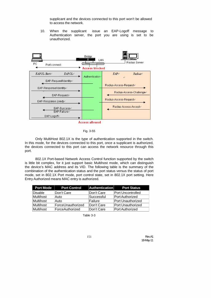
151 Rev.A118-May-11
supplicant and the devices connected to this port won’t be allowedto access the network.
10. When the supplicant issue an EAP-Logoff message toAuthentication server, the port you are using is set to beunauthorized.
Fig. 3-55
Only MultiHost 802.1X is the type of authentication supported in the switch.In this mode, for the devices connected to this port, once a supplicant is authorized,the devices connected to this port can access the network resource through thisport.
802.1X Port-based Network Access Control function supported by the switchis little bit complex, for it just support basic Multihost mode, which can distinguishthe device’s MAC address and its VID. The following table is the summary of thecombination of the authentication status and the port status versus the status of portmode, set in 802.1X Port mode, port control state, set in 802.1X port setting. HereEntry Authorized means MAC entry is authorized.
Port Mode Port Control Authentication Port StatusDisable Don’t Care Don’t Care Port UncontrolledMultihost Auto Successful Port AuthorizedMultihost Auto Failure Port UnauthorizedMultihost ForceUnauthorized Don’t Care Port UnauthorizedMultihost ForceAuthorized Don’t Care Port Authorized
Table 3-3

Rev.A118-May-11
152
3-10-1.Server
Function name:
802.1X Server Configuration
Function description:
This function is used to configure the global parameters for RADIUSauthentication in 802.1X port security application.
Parameter description:Fig. 3-144
Authentication Server 1 and 2
Server IP Server:
Server IP address for authentication.
Default: 192.168.1.77
UDP Port:
Default port number is 1812.

153 Rev.A118-May-11
Secret Key:
The secret key between authentication server and authenticator. It is astring with the length 1 – 31 characters. The character string maycontain upper case, lower case and 0-9. It is character sense. It is notallowed for putting a blank between any two characters.
Default: Radius
Accounting Server 1 and 2
Server IP Server:
Server IP address for authentication.
Default: 192.168.1.77
UDP Port:
Default port number is 1812.
Secret Key:
The secret key between authentication server and authenticator. It is astring with the length 1 – 31 characters. The character string maycontain upper case, lower case and 0-9. It is character sense. It is notallowed for putting a blank between any two characters.
Default: Radius

Rev.A118-May-11
154
3-10-2.Port Configuration
Function name:
802.1X Port Configuration
Function description:
This function is used to configure the parameters for each port in 802.1X portsecurity application. Refer to the following parameters description for details.
Parameter description:Fig. 3-145
Port:
It is the port number to be selected for configuring its associated 802.1Xparameters which are Port control, reAuthMax, txPeriod, Quiet Period,reAuthEnabled, reAuthPeriod, max. Request, suppTimeout,serverTimeout and Controlled direction.
Mode:
Range: Disable / Normal / Advanced / Clientless
Disable:
Disable IEEE 802.1X for this port.
Normal:
All clients under this port will be authorized when one of the clientdo 802.1X authentication successfully.

155 Rev.A118-May-11
Advanced:
Each clients under this port have to do 802.1X authentication byhimself.
Clientless:
The clients don’t need to install 802.1X client function, that meansthe client PC (for example WINDOW XP) does not need to enable802.1X client function also can do 802.1X authentication. But thenetwork maintainer need to configure the Radius server using eachclient’s MAC address for Radius account ID and password.
Port Control:
This is used to set the operation mode of authorization. There are threetype of operation mode supported, ForceUnauthorized, ForceAuthorized,Auto.
ForceUnauthorized:
The controlled port is forced to hold in the unauthorized state.
ForceAuthorized:
The controlled port is forced to hold in the authorized state.
Auto:
The controlled port is set to be in authorized state or unauthorizedstate depends on the result of the authentication exchange betweenthe authentication server and the supplicant.
Default: Auto
reAuthMax(1-10):
The number of authentication attempt that is permitted before the portbecomes unauthorized.
Default: 2 txPeriod(1-
65535 s):
A time period to transmitted EAPOL PDU between the authenticator andthe supplicant.
Default: 30
Quiet Period(0-65535 s):
A period of time during which we will not attempt to access the supplicant.
Deafult: 60 seconds
reAuthEnabled:
Choose whether regular authentication will take place in this port.
Default: ON
reAuthPeriod(1-65535s):
A non-zero number seconds between the periodic re-authentication ofthe supplicant.
Default: 3600

Rev.A118-May-11
156
max. Request(1-10):
The maximum of number times that the authenticator will retransmit anEAP Request to the supplicant before it times out the authenticationsession. The valid range: 1 – 10.
Default: 2 times
suppTimeout(1-65535s):
A timeout condition in the exchange between the authenticator and thesupplicant. The valid range: 1 –65535.
Default: 30 seconds. serverTimeout(1-
65535 s):
A timeout condition in the exchange between the authenticator and theauthentication server. The valid range: 1 –65535.
Default: 30 seconds
VlanAssignment:
This is used to set the Vlan Assignment with RADIUS server .
Default: Disable.
GuestVlan:
This is used to set the Guest VLAN ID with RADIUS server .
Default: 0 (N/A).
AuthFailedVlan:
This is used to set the Authentication Failed VLAN ID with RADIUSserver .
Default: 0 (N/A).

157 Rev.A118-May-11
3-10-3.Status
Function name:
802.1X Status
Function description:
Show the each port IEEE 802.1X authentication current operating mode andstatus.
Fig. 3-146
Parameter description:
Port:
Port number: 1-8
Mode:
Show this port IEEE 802.1X operating mode: There are four modesDisable, Normal, Advance and Clientless
Status:Show this port IEEE 802.1X security current status: Authorized or Unauthorized
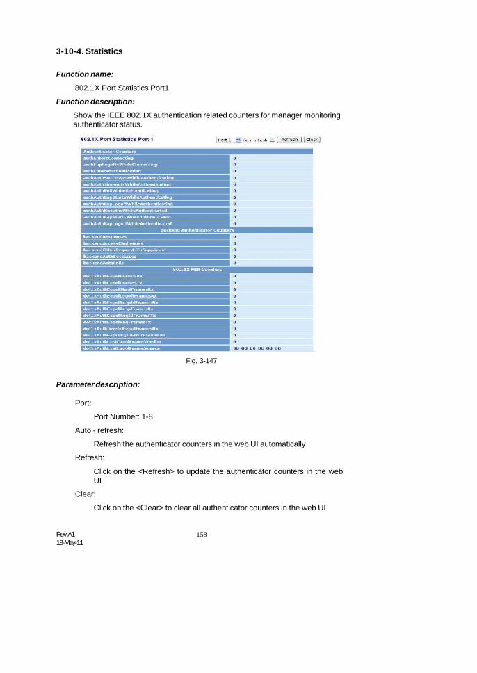
Rev.A118-May-11
158
3-10-4. Statistics
Function name:
802.1X Port Statistics Port1
Function description:
Show the IEEE 802.1X authentication related counters for manager monitoringauthenticator status.
Fig. 3-147
Parameter description:
Port:
Port Number: 1-8
Auto - refresh:
Refresh the authenticator counters in the web UI automatically
Refresh:
Click on the <Refresh> to update the authenticator counters in the webUI
Clear:
Click on the <Clear> to clear all authenticator counters in the web UI

159 Rev.A118-May-11
3-11. TACACS+TACACS+ (Terminal Access Controller Access-Control System Plus) is a
protocol which provides access control for the switch via one or more centralizedservers. It provides separate authentication, authorization and accounting services.TACACS+ utilizes TCP port 49. It consists of three separate protocols, which can, ifdesired, be implemented on separate servers.
3-11-1. State
Function name:
TACACS+ Setting
Function description:
The switch supports the TACACS+ is facilitated through AAA and can beenabled only through AAA commands which detailed accounting information andflexible administrative control over authentication and authorization processes.Providing to set TACACS+ Server IP address and Secret Key.
Fig. 3-147-1
Parameter description:
Server IP Address 1:
Server 1 IP address for authentication.
Default: 0.0.0.0
Server IP Address 2:
Server 2 IP address for authentication.
Default: 0.0.0.0
Secret Key:
The secret key between authentication server and authenticator. It is astring with the length 1 – 31 characters. The character string may containupper case, lower case and 0-9. It is character sense. It is not allowed forputting a blank between any two characters.
Default: TACACS

Rev.A118-May-11
160
3-11-2. Authentication
Function name:
AuthenticationConfiguration
Function description:
The switch supports including Console, Telnet and Web authenticationmethod via TACACS+ server .
Fig. 3-147-1
Parameter description:
Console:
To set console authentication method with Login primary or Loginsecondary.
Default: Primary is “Local” and Secondary is “None”
Telnet:
To set Telnet authentication method with Login primary or Loginsecondary.
Default: Primary is “Local” and Secondary is “None”
Web:
To set Web authentication method with Login primary or Login secondary.
Default: Primary is “Local” and Secondary is “None”
Authentication retry:
To set the Authentication retry for all three login authentication methods.
Range: 1-3 and default is 3
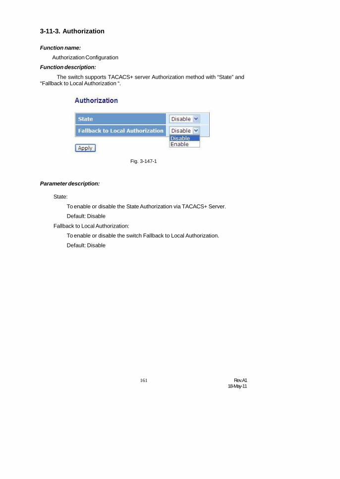
161 Rev.A118-May-11
3-11-3. Authorization
Function name:Authorization Configuration
Function description:
The switch supports TACACS+ server Authorization method with “State” and“Fallback to Local Authorization “.
Fig. 3-147-1
Parameter description:
State:
To enable or disable the State Authorization via TACACS+ Server.
Default: Disable
Fallback to Local Authorization:
To enable or disable the switch Fallback to Local Authorization.
Default: Disable

Rev.A118-May-11
162
3-11-4. Accounting
Function name:Accounting Configuration
Function description:
The switch supports TACACS+ server Accounting method with “Enable” and“Disable “ for manage login traffic accounting.
Fig. 3-147-1
Parameter description:
State:
To enable or disable the accounting via TACACS+ Server.
Default: Disable

163 Rev.A118-May-11
3-12. Trunking ConfigurationThe Port Trunking Configuration is used to configure the settings of Link
Aggregation. You can bundle more than one port with the same speed, full duplexand the same MAC to be a single logical port, thus the logical port aggregates thebandwidth of these ports. This means you can apply your current Ethernetequipments to build the bandwidth aggregation. For example, if there are threeFast Ethernet ports aggregated in a logical port, then this logical port has bandwidththree times as high as a single Fast Ethernet port has.
The switch supports two kinds of port trunking methods:
LACP:
Ports using Link Aggregation Control Protocol (according to IEEE802.3ad specification) as their trunking method can choose their uniqueLACP GroupID (1~4) to form a logic “trunked port”. The benefit of usingLACP is that a port makes an agreement with its peer port before itbecomes a ready member of a “trunk group” (also called aggregator).LACP is safer than the other trunking method - static trunk.
The switch LACP does not support the followings:
Link Aggregation across switches
Aggregation with non-IEEE 802.3 MAC link
Operating in half-duplex mode
Aggregate the ports with different data rates
Static Trunk:
Ports using Static Trunk as their trunk method can choose their uniqueStatic GroupID (also 1~4, this Static groupID can be the same withanother LACP groupID) to form a logic “trunked port”. The benefit ofusing Static Trunk method is that a port can immediately become amember of a trunk group without any handshaking with its peer port. Thisis also a disadvantage because the peer ports of your static trunk groupmay not know that they should be aggregate together to form a “logictrunked port”. Using Static Trunk on both end of a link is stronglyrecommended. Please also note that low speed links will stay in “notready” state when using static trunk to aggregate with high speed links.
As to system restrictions about the port aggregation function on the switch,In the management point of view, the switch supports maximum 8 trunk groups forLACP and additional 8 trunk groups for Static Trunk. But in the system capabilityview, only 8 “real trunked” groups are supported. An LACP trunk group with morethan one ready member-ports is a “real trunked” group. An LACP trunk group withonly one or less than one ready member-ports is not a “real trunked” group. AnyStatic trunk group is a “real trunked” group.
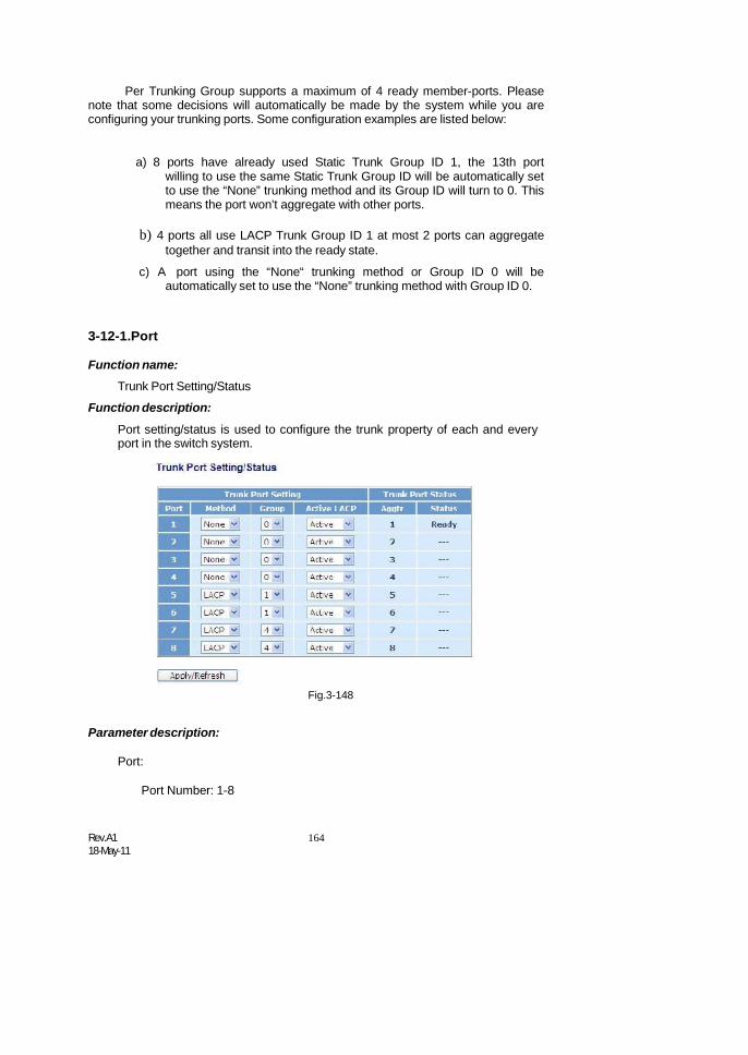
Rev.A118-May-11
164
Per Trunking Group supports a maximum of 4 ready member-ports. Pleasenote that some decisions will automatically be made by the system while you areconfiguring your trunking ports. Some configuration examples are listed below:
a) 8 ports have already used Static Trunk Group ID 1, the 13th portwilling to use the same Static Trunk Group ID will be automatically setto use the “None” trunking method and its Group ID will turn to 0. Thismeans the port won’t aggregate with other ports.
b) 4 ports all use LACP Trunk Group ID 1 at most 2 ports can aggregatetogether and transit into the ready state.
c) A port using the “None“ trunking method or Group ID 0 will beautomatically set to use the “None” trunking method with Group ID 0.
3-12-1.Port
Function name:
Trunk Port Setting/Status
Function description:
Port setting/status is used to configure the trunk property of each and everyport in the switch system.
Fig.3-148
Parameter description:
Port:
Port Number: 1-8

165 Rev.A118-May-11
Method:
This determines the method a port uses to aggregate with other ports.
None:
A port does not want to aggregate with any other port shouldchoose this default setting.
LACP:
A port use LACP as its trunk method to get aggregated with otherports also using LACP.
Group:
Static:
A port use Static Trunk as its trunk method to get aggregated withother ports also using Static Trunk.
Ports choosing the same trunking method other than “None” must beassigned a unique Group number (i.e. Group ID, valid value is from 1 to8) in order to declare that they wish to aggregate with each other.
Active LACP:
This field is only referenced when a port’s trunking method is LACP.
Aggtr:
Active:
An Active LACP port begins to send LACPDU to its link partner rightafter the LACP protocol entity started to take control of this port.
Passive:
A Passive LACP port will not actively send LACPDU out before itreceives an LACPDU from its link partner.
Aggtr is an abbreviation of “aggregator”. Every port is also an aggregator,and its own aggregator ID is the same as its own Port No. We can regardan aggregator as a representative of a trunking group. Ports with sameGroup ID and using same trunking method will have the opportunity toaggregate to a particular aggregator port. This aggregator port is usuallythe port with the smallest Port No. within the trunking group.
Status:
This field represents the trunking status of a port which uses a trunkingmethod other than “None”. It also represents the management link statusof a port which uses the “None” trunking method. “---“ means “not ready”
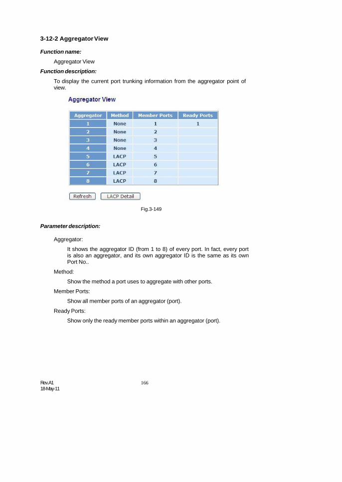
Rev.A118-May-11
166
3-12-2 AggregatorView
Function name:
Aggregator View
Function description:
To display the current port trunking information from the aggregator point ofview.
Fig.3-149
Parameter description:
Aggregator:
It shows the aggregator ID (from 1 to 8) of every port. In fact, every portis also an aggregator, and its own aggregator ID is the same as its ownPort No..
Method:
Show the method a port uses to aggregate with other ports.
Member Ports:
Show all member ports of an aggregator (port).
Ready Ports:
Show only the ready member ports within an aggregator (port).
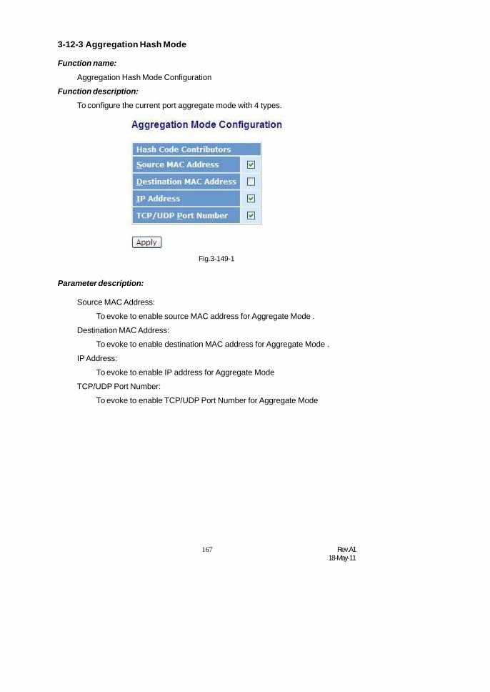
167 Rev.A118-May-11
3-12-3 Aggregation Hash Mode
Function name:
Aggregation Hash Mode Configuration
Function description:
To configure the current port aggregate mode with 4 types.
Fig.3-149-1
Parameter description:
Source MAC Address:
To evoke to enable source MAC address for Aggregate Mode .
Destination MAC Address:
To evoke to enable destination MAC address for Aggregate Mode .
IP Address:
To evoke to enable IP address for Aggregate Mode
TCP/UDP Port Number:
To evoke to enable TCP/UDP Port Number for Aggregate Mode

Rev.A118-May-11
168
3-12-4 LACP System Priority
Function name:
LACP System Priority
Function description:
It is used to set the priority part of the LACP system ID. LACP will onlyaggregate together the ports whose peer link partners are all on a singlesystem. Each system supports LACP will be assigned a globally uniqueSystem Identifier for this purpose. A system ID is a 64-bit field comprising a48-bit MAC Address and 16-bit priority value. The System Priority can be setby the user. Its range is from 1 to 65535. Default: 32768
Fig. 3-150
Parameter description:
System Priority:
Show the System Priority part of a system ID.(1-65535)

169 Rev.A118-May-11
3-13 STP ConfigurationThe Spanning Tree Protocol (STP) is a standardized method (IEEE 802.1D)
for avoiding loops in switched networks. When STP is enabled, ensure that onlyone path is active between any two nodes on the network at a time. User canenable Spanning Tree Protocol on switch’s web management and then set up otheradvanced items. We recommend that you enable STP on all switches to ensure asingle active path on the network.
3-13-1. StatusFunction name:
STP Status
Function description:
In the Spanning Tree Status, user can read 12 parameters to know STPcurrent status. The 12 parameters’ description is listed in the following table.
Parameter description:
STP State:
Fig. 3-151
Show the current STP Enabled / Disabled status. Default is “Disabled”.
Bridge ID:
Show switch’s bridge ID which stands for the MAC address of this switch.
Bridge Priority:
Show this switch’s current bridge priority setting. Default is 32768.
Designated Root:
Show root bridge ID of this network segment. If this switch is a rootbridge, the “Designated Root” will show this switch’s bridge ID.

Rev.A118-May-11
170
Designated Priority:
Show the current root bridge priority.
Root Port:
Show port number connected to root bridge with the lowest path cost.
Root Path Cost:
Show the path cost between the root port and the designated port of theroot bridge.
Current Max. Age:
Show the current root bridge maximum age time. Maximum age time isused to monitor if STP topology needs to change. When a bridge doesnot receive a hello message from root bridge until the maximum age timeis counted down to 0, the bridge will treat the root bridge malfunctionedand issue a Topology Change Notification (TCN) BPDU to all otherbridges.
All bridges in the LAN will re-learn and determine which the root bridge is.Maximum Age time is assigned by root bridge in unit of seconds. Defaultis 20 seconds.
Current Forward Delay:
Show the current root bridge forward delay time. The value of ForwardDelay time is set by root. The Forward Delay time is defined as the timespent from Listening state moved to Learning state or from Learningstate moved to Forwarding state of a port in bridge.
Hello Time:
Show the current hello time of the root bridge. Hello time is a timeinterval specified by root bridge, used to request all other bridgesperiodically sending hello message every “hello time” seconds to thebridge attached to its designated port.
STP Topology Change Count:
STP Topology Change Count expresses the time spent in unit of secondssince the beginning of the Spanning Tree Topology Change to the end ofthe STP convergence. Once the STP change is converged, the TopologyChange count will be reset to 0. The figures showing in the screen maynot be the exact time it spent but very close to, because the time iseclipsing.
Time Since Last Topology Change:
Time Since Last Topology Change is the accumulated time in unit ofseconds the STP has been since the last STP Topology Change wasmade. When Topology Change is initiated again, this counter will bereset to 0. And it will also count again once STP topology Change iscompleted.

171 Rev.A118-May-11
3-13-2. ConfigurationThe STP, Spanning Tree Protocol, actually includes RSTP. In the Spanning
Tree Configuration, there are six parameters open for the user to configure asuser’s idea. Each parameter description is listed below.
Function name:
STP Configuration
Function description:
User can set the following Spanning Tree parameters to control STP functionenable/disable, select mode RSTP/STP and affect STP state machinebehavior to send BPDU in this switch. The default setting of Spanning TreeProtocol is “Disable”.
Parameter description:
Spanning Tree Protocol:
Fig. 3-152
Set 802.1W Rapid STP function Enable / Disable. Default is “Disable”
Bridge Priority:
The lower the bridge priority is, the higher priority it has. Usually, thebridge with the highest bridge priority is the root. If you want to have theSM8P-SFP as root bridge, you can set this value lower than that ofbridge in the LAN. The valid value is 0 ~ 61440. The default is 32768.
Hello Time:
Hello Time is used to determine the periodic time to send normal BPDUfrom designated ports among bridges. It decides how long a bridgeshould send this message to other bridge to tell I am alive. When theSM8P-SFP is the root bridge of the LAN, for example, all other bridgeswill use the hello time assigned by this switch to communicate with eachother. The valid value is 1 ~ 10 in unit of second.

Rev.A118-May-11
172
Default is 2 seconds.
Max. Age:
When the SM8P-SFP is the root bridge, the whole LAN will apply thisfigure set by this switch as their maximum age time. When a bridgereceived a BPDU originated from the root bridge and if the message ageconveyed in the BPDU exceeds the Max. Age of the root bridge, thebridge will treat the root bridge malfunctioned and issue a TopologyChange Notification (TCN) BPDU to all other bridges. All bridges in theLAN will re-calculate and determine who the root bridge is. The validvalue of Max. Age is 6 ~ 40 seconds. Default is 20 seconds.
Forward Delay:
You can set the root bridge forward delay time. This figure is set by rootbridge only. The forward delay time is defined as the time spent fromListening state moved to Learning state and also from Learning statemoved to Forwarding state of a port in bridge. The forward delay timecontains two states, Listening state to Learning state and Learning stateto Forwarding state. It assumes that forward delay time is 15 seconds,then total forward delay time will be 30 seconds. This has much to dowith the STP convergent time which will be more than 30 secondsbecause some other factors.
The valid value is 4 ~ 30 seconds, default is 15 seconds.
Force Version:
Two options are offered for the user’s choosing STP algorithm. One isRSTP and the other is STP. If STP is chosen, RSTP will run as a legacySTP. The switch supports RSTP (802.1w) which is backward compatiblewith STP (802.1d).
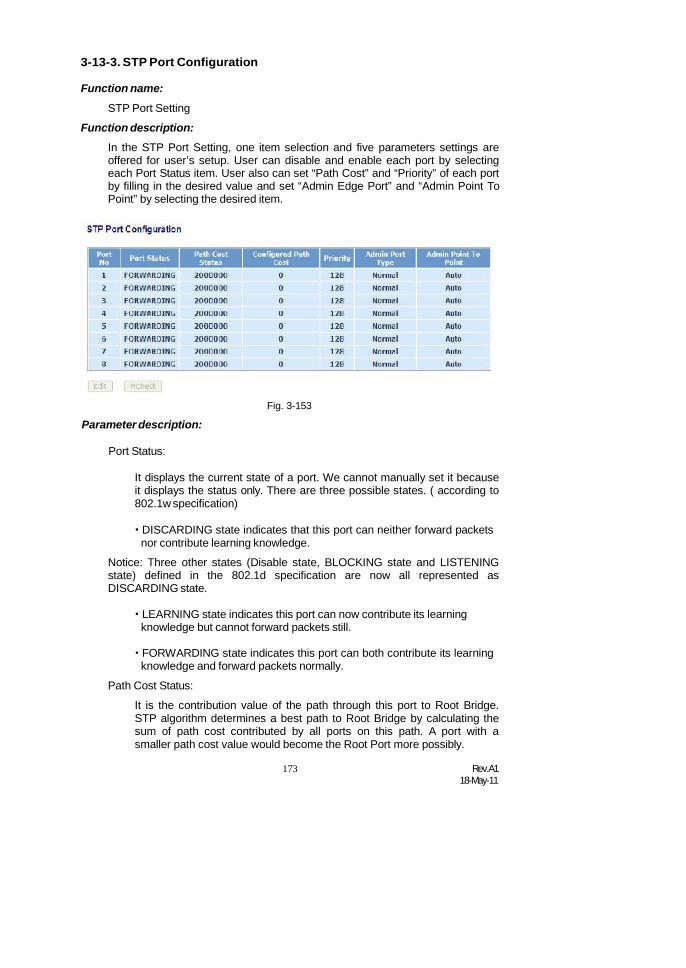
173 Rev.A118-May-11
3-13-3. STP Port Configuration
Function name:
STP Port Setting
Function description:
In the STP Port Setting, one item selection and five parameters settings areoffered for user’s setup. User can disable and enable each port by selectingeach Port Status item. User also can set “Path Cost” and “Priority” of each portby filling in the desired value and set “Admin Edge Port” and “Admin Point ToPoint” by selecting the desired item.
Parameter description:
Port Status:
Fig. 3-153
It displays the current state of a port. We cannot manually set it becauseit displays the status only. There are three possible states. ( according to802.1w specification)
DISCARDING state indicates that this port can neither forward packetsnor contribute learning knowledge.
Notice: Three other states (Disable state, BLOCKING state and LISTENINGstate) defined in the 802.1d specification are now all represented asDISCARDING state.
LEARNING state indicates this port can now contribute its learningknowledge but cannot forward packets still.
FORWARDING state indicates this port can both contribute its learningknowledge and forward packets normally.
Path Cost Status:
It is the contribution value of the path through this port to Root Bridge.STP algorithm determines a best path to Root Bridge by calculating thesum of path cost contributed by all ports on this path. A port with asmaller path cost value would become the Root Port more possibly.

Rev.A118-May-11
174
Configured Path Cost:
The range is 0 – 200,000,000. In the switch, if path cost is set to be zero,the STP will get the recommended value resulted from auto-negotiationof the link accordingly and display this value in the field of Path CostStatus. Otherwise, it may show the value that the administrator set up inConfigured Path Cost and Path Cost Status.802.1w RSTP recommended value: (Valid range: 1 – 200,000,000)
10 Mbps : 2,000,000
100 Mbps : 200,000
1 Gbps : 20,000
Default: 0
Priority:
Priority here means Port Priority. Port Priority and Port Number aremixed to form the Port ID. Port IDs are often compared in order todetermine which port of a bridge would become the Root Port. The rangeis 0 – 240.
Default is 128.
Admin Edge Port:
If user selects “Yes”, this port will be an edge port. An Edge Port is a portconnected to a device that knows nothing about STP or RSTP. Usually,the connected device is an end station. Edge Ports will immediatelytransit to forwarding state and skip the listening and learning statebecause the edge ports cannot create bridging loops in the network. Thiswill expedite the convergence. When the link on the edge port toggles,the STP topology keeps unchanged. Unlike the designate port or rootport though, an edge port will transit to a normal spanning-tree portimmediately if it receives a BPDU.
Default: No
Admin Point To Point:
We say a port is a point-to-point link, from RSTP’s view, if it is in full-duplex mode but is shared link if it is in half-duplex mode. RSTP fastconvergence can only happen on point-to-point links and on edge ports.This can expedite the convergence because this will have the port fasttransited to forwarding state.
There are three parameters, Auto, True and False, used to configure thetype of the point-to-point link. If configure this parameter to be Auto, itmeans RSTP will use the duplex mode resulted from the auto-negotiation.In today’s switched networks, most links are running in full-duplex mode.For sure, the result may be half-duplex, in this case, the port will not fasttransit to Forwarding state. If it is set as True, the port is treated as point-to-point link by RSTP and unconditionally transited to Forwarding state. Ifit is set as False, fast transition to Forwarding state will not happen onthis port.

175 Rev.A118-May-11
Default: Auto
M Check:
Migration Check. It forces the port sending out an RSTP BPDU insteadof a legacy STP BPDU at the next transmission. The only benefit of thisoperation is to make the port quickly get back to act as an RSTP port.Click <M Check> button to send a RSTP BPDU from the port youspecified.
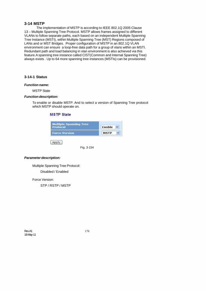
Rev.A118-May-11
176
3-14 MSTPThe implementation of MSTP is according to IEEE 802.1Q 2005 Clause
13 – Multiple Spanning Tree Protocol. MSTP allows frames assigned to differentVLANs to follow separate paths, each based on an independent Multiple SpanningTree Instance (MSTI), within Multiple Spanning Tree (MST) Regions composed ofLANs and or MST Bridges. Proper configuration of MSTP in an 802.1Q VLANenvironment can ensure a loop-free data path for a group of vlans within an MSTI.Redundant path and load balancing in vlan environment is also achieved via thisfeature.A spanning tree instance called CIST(Common and Internal Spanning Tree)always exists . Up to 64 more spanning tree instances (MSTIs) can be provisioned.
3-14-1 Status
Function name:MSTP State
Function description:
To enable or disable MSTP. And to select a version of Spanning Tree protocolwhich MSTP should operate on.
Fig. 3-154
Parameter description:
Multiple Spanning Tree Protocol:
Disabled / Enabled
Force Version:
STP / RSTP / MSTP

177 Rev.A118-May-11
3-14-2 Region Config
Function name:
MSTP Region Config
Function description:
To configure the basic identification of a MSTP bridge. Bridges participating ina common MST region must have the same Region Name and Revision Level.
Fig. 3-155
Parameter description:
Region Name:
0-32 characters.(A variable length text string encoded within a fixed fieldof 32 octets , conforming to RFC 2271’s definition of SnmpAdminString.)
Revision Level:
0-65535

Rev.A118-May-11
178
3-14-3 Instance View
Function name:
MSTP Instance Config
Function description:
Providing an MST instance table which include information(vlan membershipof a MSTI ) of all spanning instances provisioned in the particular MST regionwhich the bridge belongs to. Through this table, additional MSTP configurationdata can be applied and MSTP status can be retrieved.
Fig. 3-156
Parameter description:
Instance ID:
Every spanning tree instance need to have a unique instance ID within0~4095. Instance 0 (CIST) always exists and can not be deleted.Additional spanning instances (MSTIs) can be added or deleted. At leastone vlan must be provisioned for an MSTI to declare the need for theMSTI to be existent.
Corresponding Vlans: 0-
4095.
Multiple vlans can belong to an MSTI. All vlans that are not provisionedthrough this will be automatically assigned to Instance 0(CIST).
Edit MSTI / Vlan: Fig. 3-157
To add an MSTI and provide its vlan members or modify vlan membersfor a specific MSTI.

179 Rev.A118-May-11
Del MSTI:
To delete an MSTI.
Del All MSTI:
Deleting all provisioned MSTIs at a time.
Instance Configuration: Fig. 3-158
To provision spanning tree performance parameters per instance.
Port Config: Fig. 3-159
To provision spanning tree performance parameters per instance per port.
Instance Status: Fig. 3-160
To show the status report of a particular spanning tree instance.
Port Status: Fig. 3-161
To show the status report of all ports regarding a specific spanning treeinstance.
Parameter description:
Vlan Mapping:
VID STRING
Fig. 3-157 Edit MSTI / Vlan
VID STRING Example:
2.5-7.100-200.301.303.1000-1500 (Valid VID Range:1-4094)

Rev.A118-May-11
180
Fig. 3-158 Instance Config
Parameter description:
Priority: The priority parameter used in the CIST(Common and InternalSpanning Tree) connection.
0 / 4096 / 8192 / 12288 / 16384 / 20480 / 24576 / 28672 / 32768 / 36864/ 40960 / 45056 / 49152 / 53248 / 57344 / 61440
MAX. Age:
6-40sec. The same definition as in the RSTP protocol.
Forward Delay:
4-30sec. The same definition as in the RSTP protocol.
MAX. Hops:
6-40sec. It’s a new parameter for the multiple spanning tree protocol. It isused in the internal spanning tree instances. “CIST Remaining Hops” or“MSTI Remaining Hops” in the Spanning tree protocol message woulddecreased by one when the message is propagated to the neighboringbridge. If the Remaining Hops in a message is zero, the message (BPDU)would be regarded as invalid. Max Hops is used to specify the initialvalue of the Remaining Hops for Regional Root Bridge (Either CISTRegional Root or MSTI Regional Root)

181 Rev.A118-May-11
Parameter description:Fig. 3-159 Port Config
Port:
1- 8
Path Cost:
1 – 200,000,000
The same definition as in the RSTP specification. But in MSTP, thisparameter can be respectively applied to ports of CIST and ports of anyMSTI.
Priority:
0 / 16 / 32 / 48 / 64 / 80 / 96 / 112 / 128 / 144 / 160 / 176 / 192 / 208 / 224/ 240
The same definition as in the RSTP specification. But in MSTP, thisparameter can be respectively applied to ports of CIST and ports of anyMSTI.
Hello Time:
1 / 2
In contrast with RSTP, Hello Time in MSTP is a per port setting for theCIST.
Admin Edge:
Yes / No
The same definition as in the RSTP specification for the CIST ports.
Admin P2P:
Auto / True / False
The same definition as in the RSTP specification for the CIST ports.
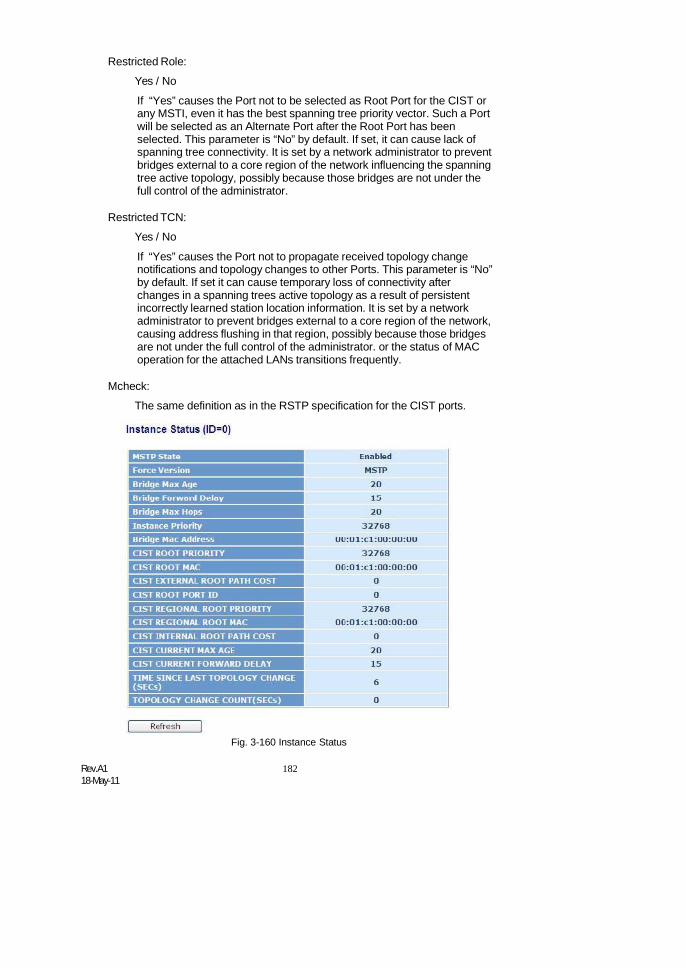
Rev.A118-May-11
182
Restricted Role:
Yes / No
If “Yes” causes the Port not to be selected as Root Port for the CIST orany MSTI, even it has the best spanning tree priority vector. Such a Portwill be selected as an Alternate Port after the Root Port has beenselected. This parameter is “No” by default. If set, it can cause lack ofspanning tree connectivity. It is set by a network administrator to preventbridges external to a core region of the network influencing the spanningtree active topology, possibly because those bridges are not under thefull control of the administrator.
Restricted TCN:
Yes / No
If “Yes” causes the Port not to propagate received topology changenotifications and topology changes to other Ports. This parameter is “No”by default. If set it can cause temporary loss of connectivity afterchanges in a spanning trees active topology as a result of persistentincorrectly learned station location information. It is set by a networkadministrator to prevent bridges external to a core region of the network,causing address flushing in that region, possibly because those bridgesare not under the full control of the administrator. or the status of MACoperation for the attached LANs transitions frequently.
Mcheck:
The same definition as in the RSTP specification for the CIST ports.
Fig. 3-160 Instance Status

183 Rev.A118-May-11
Parameter description:
MSTP State:
MSTP protocol is Enable or Disable.
Force Version:
It shows the current spanning tree protocol version configured.
Bridge Max Age:
It shows the Max Age setting of the bridge itself.
Bridge Forward Delay:
It shows the Forward Delay setting of the bridge itself.
Bridge Max Hops:
It shows the Max Hops setting of the bridge itself.
Instance Priority:
Spanning tree priority value for a specific tree instance(CIST or MSTI)
Bridge Mac Address:
The Mac Address of the bridge itself.
CIST ROOT PRIORITY:
Spanning tree priority value of the CIST root bridge
CIST ROOT MAC:
Mac Address of the CIST root bridge
CIST EXTERNAL ROOT PATH COST:
Root path cost value from the point of view of the bridge’s MST region.
CIST ROOT PORT ID:
The port ID of the bridge’s root port. In MSTP, peer port of a root portmay reside in defferent MST region or in the same MST region.The firstcase indicates that the root port’s owner is the CIST regional root bridge.
CIST REGIONAL ROOT PRIORITY:
Spanning tree priority value of the CIST regional root bridge.Note thatCIST Regional Root bridge is different from CIST Root bridge.Oneexception is that when a bridge belonging to an MST region happens tobe the root bridge of the CST(Common Spanning Tree). An MST Regionin the CST can be regarded as a common RSTP bridge.The IST(InternalSpanning Tree) and MSTIs are transparent to bridges outside this region.
CIST REGIONAL ROOT MAC:

Rev.A118-May-11
184
Mac Address of the CIST regional root bridge.
CIST INTERNAL ROOT PATH COST:
Root path cost value from the point of view of the bridges inside the IST.
CIST CURRENT MAX AGE:
Max Age of the CIST Root bridge.
CIST CURRENT FORWARD DELAY:
Forward Delay of the CIST Root bridge.
TIME SINCE LAST TOPOLOGY CHANGE(SECs):
Time Since Last Topology Change is the elapsed time in unit of secondsfor a bunch of “Topology Change and(or) Topology Change Notificationreceiving” to occur. When new series of Topology Changes occur again,this counter will be reset to 0.
TOPOLOGY CHANGE COUNT(SECs):
The per spanning tree instanceTopology Change Count expresses thetime spent in unit of seconds since the beginning of the Spanning TreeTopology Change to the end of the STP convergence. Once there is notopology change occurring and no more topology change notificationreceived, the Topology Change count will be reset to 0.
Parameter description:
Port No:1- 8
Status:
Fig. 3-161 Port Status
The forwarding status.Same definition as of the RSTP specificationPossible values are “FORWARDING” , “LEARNING” , “DISCARDING”
Status:The role that a port plays in the spanning tree topology. Possible valuesare “dsbl”(disable port) , ”alt”(alternate port) , “bkup”(backup port) ,“ROOT”(root port) , “DSGN”(designated port) , “MSTR”(master port). Thelast 3 are possible port roles for a port to transit to FORWARDING state
Path Cost:Display currently resolved port path cost value for each port in a

185 Rev.A118-May-11
particular spanning tree instance.Priority:
Display port priority value for each port in a particular spanning treeinstance.
Hello:per port Hello Time display. It takes the following form:Current Hello Time/Hello Time Setting
Oper. Edge:Whether or not a port is an Edge Port in reality.
Oper. P2P:Whether or not a port is a Point-to-Point Port in reality.
Restricted Role:Same as mentioned in “Port Config”
Restricted Tcn:Same as mentioned in “Port Config”
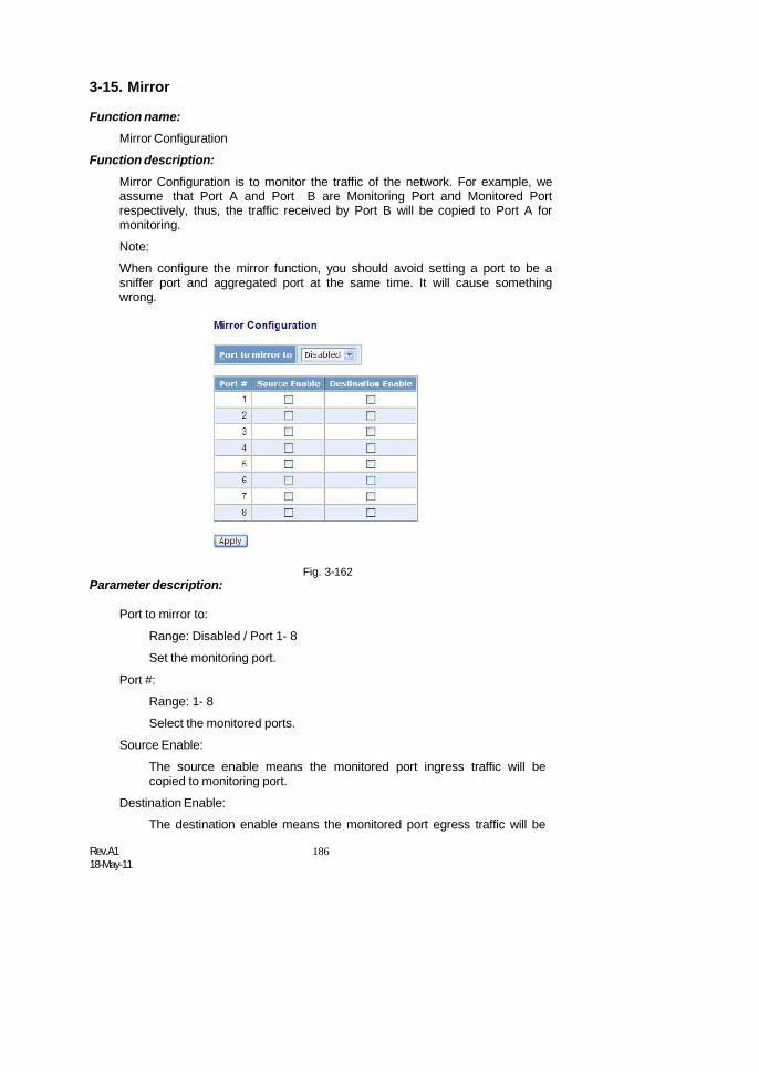
Rev.A118-May-11
186
3-15. Mirror
Function name:Mirror Configuration
Function description:
Mirror Configuration is to monitor the traffic of the network. For example, weassume that Port A and Port B are Monitoring Port and Monitored Portrespectively, thus, the traffic received by Port B will be copied to Port A formonitoring.
Note:
When configure the mirror function, you should avoid setting a port to be asniffer port and aggregated port at the same time. It will cause somethingwrong.
Parameter description:Fig. 3-162
Port to mirror to:
Range: Disabled / Port 1- 8
Set the monitoring port.
Port #:
Range: 1- 8
Select the monitored ports.
Source Enable:
The source enable means the monitored port ingress traffic will becopied to monitoring port.
Destination Enable:
The destination enable means the monitored port egress traffic will be

187 Rev.A118-May-11
copied to monitoring port.

Rev.A118-May-11
188
3-16. MulticastThe function, is used to establish the multicast groups to forward the
multicast packet to the member ports, and, in nature, avoids wasting the bandwidthwhile IP multicast packets are running over the network. This is because a switchthat does not support IGMP or IGMP Snooping can not tell the multicast packet fromthe broadcast packet, so it can only treat them all as the broadcast packet. WithoutIGMP Snooping, the multicast packet forwarding function is plain and nothing isdifferent from broadcast packet.
A switch supported IGMP Snooping with the functions of query, report andleave, a type of packet exchanged between IP Multicast Router/Switch and IPMulticast Host, can update the information of the Multicast table when a member(port) joins or leaves an IP Multicast Destination Address. With this function, once aswitch receives an IP multicast packet, it will forward the packet to the memberswho joined in a specified IP multicast group before.
The packets will be discarded by the IGMP Snooping if the user transmitsmulticast packets to the multicast group that had not been built up in advance.
3-16-1 IGMP modeFunction name:
IGMP Mode Configuration
Function description:
IGMP mode enables the switch to issue IGMP function that you enable IGMPproxy or snooping on the switch, which connects to a router closer to the rootof the tree. This interface is the upstream interface. The router on theupstream interface should be running IGMP.
Parameter description:
IGMP Mode:
Fig. 3-163-0 IGMP Mode
To scroll the IGMP mode with “Disable” , “Proxy” or “Snooping”

189 Rev.A118-May-11
3-16-2 IGMP ProxyFunction name:
IGMP Proxy Configuration
Function description:
IGMP proxy enables the switch to issue IGMP host messages on behalf ofhosts that the system discovered through standard IGMP interfaces. Theswitch acts as a proxy for its hosts.
You enable IGMP proxy on the switch, which connects to a router closer to theroot of the tree. This interface is the upstream interface. The router on theupstream interface should be running IGMP.
Parameter description:
IGMP Proxy Enable:
Fig. 3-163 IGMP Proxy
The function supports to enable the IGMP Proxy on Switch.
Enable:
To evoke the ” IGMP Proxy Enable” to enable IGMP Proxy onSwitch.
Default: Disable
Unregister IPMC Flooding Enable:
To enable to control the traffic doesn’t appear in the multicast table forflooding
General Query Interval: :
To set the switch send general query period time. (Available : 1~3600secs)
General Query Response Timeout :
To set the switch determine the client living time. (Available : 1~25 secs)
Rev.A118-May-11
190
General Query Max Response Time :
To set the max response code value of the general query packet .(Available : 1~25 secs)
Last Member Query Count :
To set the frequency. When Switch received IGMP leave then switchsend specific query frequency. (Available : 1~16 secs)
Last Member Query Interval :
To set the frequency what the Switch send specific query period time.(Available : 1~25 secs)
Last Member Query Max Response Time :
To set the max response code value in the specific query packet(Available : 1~25 secs)
Update Interval of Router Port :
To set the period time what interface ever received IGMP query packet.(Available : 1~3600 secs)
Router Ports:
To set the interface what connect to IGMP Router, and it is the switchwhat it send/receive IGMP report/leave port. Router ports may be only ormore than one.
Apply:
To save all configuration.
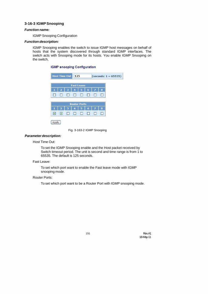
191 Rev.A118-May-11
3-16-3 IGMPSnoopingFunction name:
IGMP Snooping Configuration
Function description:
IGMP Snooping enables the switch to issue IGMP host messages on behalf ofhosts that the system discovered through standard IGMP interfaces. Theswitch acts with Snooping mode for its hosts. You enable IGMP Snooping onthe switch,
Parameter description:
Host Time Out:
Fig. 3-163-2 IGMP Snooping
To set the IGMP Snooping enable and the Host packet received bySwitch timeout period. The unit is second and time range is from 1 to65535. The default is 125 seconds.
Fast Leave:
To set which port want to enable the Fast leave mode with IGMPsnooping mode.
Router Ports:
To set which port want to be a Router Port with IGMP snooping mode.

Rev.A118-May-11
192
3-16-4 IGMP Group Allow
Function name:
IGMP Group Allow
Function description:
The Group Allow function allows the Multicast VLAN Registration to set up theIP multicast group filtering conditions. IGMP join behavior that meet the itemsyou set up will be joined or formed the multicast group.
Fig. 3-164-3 MVID Group Allow configuration
Parameter description:
IP Address Range:
The switch supports two kinds of options for managed valid IP range,including “Any” and “Custom”. Default is “Any”. In case that” Custom”had been chosen, you can assigned effective IP range. The valid rangeis 224.0.0.0~239.255.255.255.
MVID:
The switch supports two kinds of options for managed valid MVID,including “Any” and “Custom”. Default is “Any”. When you choose“Custom”, you can fill in VID number. The valid VID range is 1~4094.

193 Rev.A118-May-11
3-16-5 IGMP Group Membership
Function name:
IGMP Group Membership
Function description:
To show the IGMP group members information, the you can edit theparameters for IGMP groups and members in the web user interface.
Fig. 3-164
Parameter description:
Index:
To display current built-up multicast group entry index.
GroupAddress:
To display current built-up multicast Group Address .
VLAN ID:
To display current built-up multicast VLAN ID .
Port Members:
To display current built-up multicast port members .
Previous Page:
To display previous page context.
Next Page:
To display next page context.
Refresh:
To Update multicast group membership.

Rev.A118-May-11
194
3-16-6 MVR
Function name:
MVR configuration (Multicast VLAN Registration)
Function description:
Multicast VLAN Registration (MVR) routes packets received in a multicastsource VLAN to one or more receive VLANs. Clients are in the receive VLANsand the multicast server is in the source VLAN. Multicast routing has to bedisabled when MVR is enabled. Refer to the configuration guide atUnderstanding Multicast VLAN Registration for more information on MVR.
Note: The function must using with tag base VLAN mode.
Fig. 3-164-1 MVR configuration
Parameter description:MVR Enable:
To set the MVR function enable .
Host Time Out:
To set the MVR function enable and the Host packet received by Switchtimeout period. The unit is second and time range is from 1 to 65535.The default is 125 seconds.
Fast Leave:
To set which port want to enable the Fast leave mode with IGMPsnooping mode.

195 Rev.A118-May-11
3-16-7 MVID
Function name:
MVID configuration (Multicast VLAN Registration ID assign entry)
Function description:
To set the MVR Group member ID (MVID) entry with the Member port andRouter Port.
Fig. 3-164-2 MVID configuration
Parameter description:
Add new MVID:
Fig. 3-164-3 MVID configuration
To create a new MVID entry.
MVID:
To set the MVR Group ID .
Member Port:
To set which port will join the MVR Group member.
Router Port:
To set which port want to become the MVR Group router port.

Rev.A118-May-11
196
3-16-8 MVR Group Allow
Function name:
MVR Group Allow
Function description:
The Group Allow function allows the Multicast VLAN Registration to set up theIP multicast group filtering conditions. IGMP join behavior that meet the itemsyou set up will be joined or formed the multicast group.
Fig. 3-164-3 MVID Group Allow configuration
Parameter description:
IP Address Range:
The switch supports two kinds of options for managed valid IP range,including “Any” and “Custom”. Default is “Any”. In case that” Custom”had been chosen, you can assigned effective IP range. The valid rangeis 224.0.0.0~239.255.255.255.
MVID:
The switch supports two kinds of options for managed valid MVID,including “Any” and “Custom”. Default is “Any”. When you choose“Custom”, you can fill in VID number. The valid VID range is 1~4094.

197 Rev.A118-May-11
3-16-9 MVR Group Membership
Function name:
MVR Group Membership
Function description:
To display the MVR Group Membership information.
Fig. 3-164-4 MVID Group Membership
Parameter description:
Refresh:
Refresh function can help you to see current MVR group Membershipstatus
Previous Page:
Move to the previous page.
Next Page:
Move to the next page.

Rev.A118-May-11
198
3-17. Alarm Configuration
Alarm Configuration
Events Configuration
Email Configuration
3-17-1 Events
Function name:
Events Configuration
Function description:
The Trap Events Configuration function is used to enable the switch to sendout the trap information while pre-defined trap events occurred. The switchoffers 24 different trap events to users for switch management. The trapinformation can be sent out in two ways, including email and trap. Themessage will be sent while users tick () the trap event individually on theweb page shown as below.
Fig. 3-165

199 Rev.A118-May-11
Parameter description:
Trap: Cold Start, Warm Start, Link Down, Link Up, AuthenticationFailure, User login, User logout
STP: STP Topology Changed, STP Disabled, STP Enabled
LACP: LACP Disabled, LACP Enabled, LACP Member Added,LACP Port Failure
GVRP: GVRP Disabled, GVRP Enabled
VLAN: VLAN Disabled, Port-based VLAN Enabled, Tag-based VLANEnabled, Metro-mode Vlan Enabled, Double-tag Vlan Enabled
Module Swap: Module Inserted, Module Removed, Dual Media Swapped

Rev.A118-May-11
200
3-17-2 Email
Function name:
Email Configuration
Function description:
Alarm configuration is used to configure the persons who should receive thealarm message via email. An email address has to be set in the web page ofalarm configuration (See Fig. 3-61). Then, user can read the trap informationfrom the email. This function provides 6 email addresses at most. The 24different trap events will be sent out to SNMP Manager when trap eventoccurs. After ticking trap events, you can fill in your desired email addresses.Then, please click <Apply> button to complete the alarm configuration. It willtake effect in a few seconds.
Fig. 3-166
Parameter description:
Email:
Mail Server: the IP address of the server transferring your email.
Username: your username on the mail server.
Password: your password on the mail server.
Sender: To set the mail sender name
Return-Path: To set the mail return-path as sender mail address.
Email Address 1 – 6: email address that would like to receive thealarm message.

201 Rev.A118-May-11
3-18. DHCP Snooping
DHCP Snooping
DHCP Snooping State
DHCP Snooping Entry
DHCP Snooping Client
Fig.3-62
3-18-1. DHCP Snooping State
Function name:
DHCP Snooping State
Function description:
The addresses assigned to DHCP clients on unsecure ports can be carefullycontrolled using the dynamic bindings registered with DHCP Snooping. DHCPsnooping allows a switch to protect a network from rogue DHCP servers orother devices which send port-related information to a DHCP server. Thisinformation can be useful in tracking an IP address back to a physical port.
Fig. 3-17-1 DHCP Snooping State
Parameter description:
DHCP Snooping state: The parameter which set to disabled or enabledthe DHCP snooping function on the switch, thedefault is Disabled.
Note: To click ” Apply” when you finish the configuration.

Rev.A118-May-11
202
3-18-2. DHCP Snooping Entry
Function name:
DHCP Snooping Entry
Function description:
DHCP snooping Entry allows a switch to add the an trust DHCP server and 2trust port to build the DHCP snooping available entry. This information can beuseful in tracking an IP address back to a physical port and enable or disablethe DHCP Option 82.
Fig. 3-17-1 DHCP Snooping State
Parameter description:
VID:When DHCP snooping is enabled, and enabled on the specifiedVLAN, DHCP packet filtering will be performed on any un-trustedports within the VLAN. It set a available VLAN ID to enable the DHCPsnooping on VLAN interface.
Trust Port 1:If DHCP snooping is enabled globally, and also enabled onthe VLAN where the DHCP packet is received, all DHCP packets areforwarded for a trusted por. It set a trust port 1. available port from 0to 8. 0 is disabled.
Trust port 2 : It set a trust port 2. available port from 0 to 8. 0 is disabled.
Trust VID: It set a trust VLAN ID. available VID from 1 to 4094.
Server IP: It set a trust DHCP Server IP address for DHCP Snooping.
Option 82:It set the DHCP Option 82 function on the switch, default isDisable.
Action:It set the switch when received a client DHCP request packet thenaction for filtering. available action : keep/ drop / replace.
Note: Filtering rules are implemented as follows:
- If the DHCP snooping is disabled, all DHCP packets are forwarded.
- If DHCP snooping is enabled and also enabled on the VLAN wherethe DHCP packet is received, all DHCP packets are forwarded for atrusted port.

203 Rev.A118-May-11
- If DHCP snooping is enabled and also enabled on the VLAN wherethe DHCP packet is received, but the port is not trusted, it isprocessed as follows:
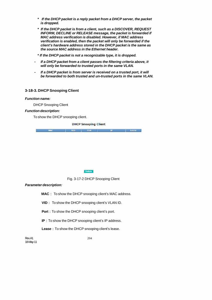
Rev.A118-May-11
204
* If the DHCP packet is a reply packet from a DHCP server, the packetis dropped.
* If the DHCP packet is from a client, such as a DISCOVER, REQUESTINFORM, DECLINE or RELEASE message, the packet is forwarded ifMAC address verification is disabled. However, if MAC addressverification is enabled, then the packet will only be forwarded if theclient’s hardware address stored in the DHCP packet is the same asthe source MAC address in the Ethernet header.
* If the DHCP packet is not a recognizable type, it is dropped.
- If a DHCP packet from a client passes the filtering criteria above, itwill only be forwarded to trusted ports in the same VLAN.
- If a DHCP packet is from server is received on a trusted port, it willbe forwarded to both trusted and un-trusted ports in the same VLAN.
3-18-3. DHCP Snooping Client
Function name:
DHCP Snooping Client
Function description:
To show the DHCP snooping client.
Parameter description:
Fig. 3-17-2 DHCP Snooping Client
MAC: To show the DHCP snooping client’s MAC address.
VID: To show the DHCP snooping client’s VLAN ID.
Port:To show the DHCP snooping client’s port.
IP:To show the DHCP snooping client’s IP address.
Lease:To show the DHCP snooping client’s lease.
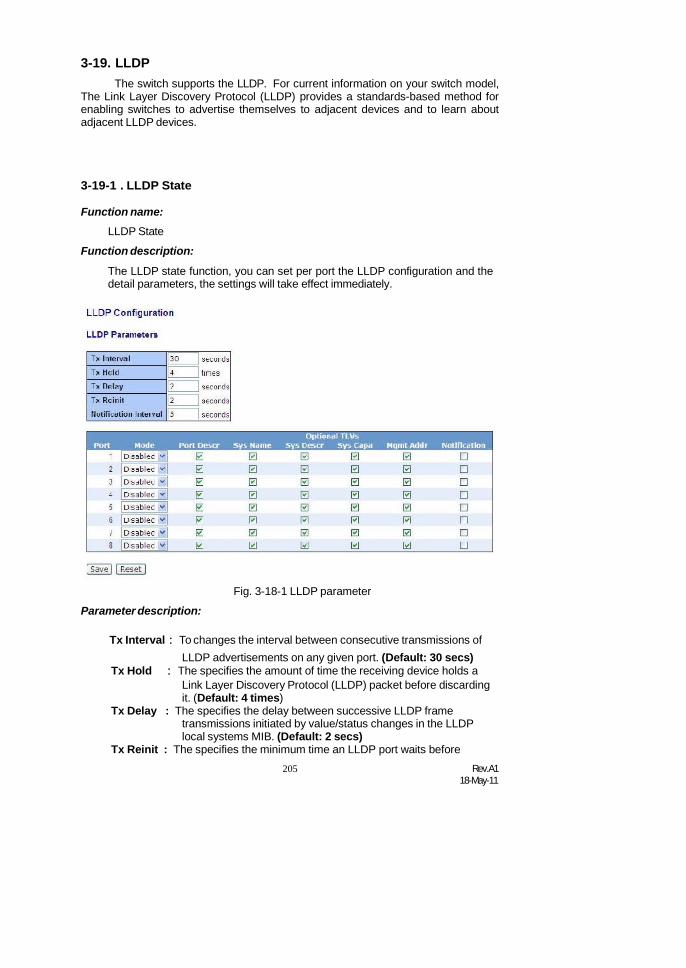
205 Rev.A118-May-11
3-19. LLDPThe switch supports the LLDP. For current information on your switch model,
The Link Layer Discovery Protocol (LLDP) provides a standards-based method forenabling switches to advertise themselves to adjacent devices and to learn aboutadjacent LLDP devices.
3-19-1 . LLDP State
Function name:LLDP State
Function description:
The LLDP state function, you can set per port the LLDP configuration and thedetail parameters, the settings will take effect immediately.
Parameter description:
Fig. 3-18-1 LLDP parameter
Tx Interval: To changes the interval between consecutive transmissions ofLLDP advertisements on any given port. (Default: 30 secs)
Tx Hold : The specifies the amount of time the receiving device holds aLink Layer Discovery Protocol (LLDP) packet before discardingit. (Default: 4 times)
Tx Delay : The specifies the delay between successive LLDP frametransmissions initiated by value/status changes in the LLDPlocal systems MIB. (Default: 2 secs)
Tx Reinit : The specifies the minimum time an LLDP port waits before

Rev.A118-May-11
206
Notificationreinitializing LLDP transmission. (Default: 2 secs)
Interval: A network management application can periodically check theswitch MIB to detect any missed change notification traps.Refer to IEEE 802.1AB-2005 or later for more information.(Default: 5 secs)
Mode : To enable or disable the LLDP mode per port. There are fourtype includes Disable, Tx_Rx, Tx only and Rx only
Port Descr : To evoke the outbound LLDP advertisements, includes analphanumeric string describing the port.
Sys Name : To evoke the outbound LLDP advertisements, includes thesystem’s assigned name
Sys Descr : To evoke outbound LLDP advertisements, includes analphanumeric string describing the full name and versionidentification for the system’s hardware type, software version,and networking application.
Sys Capa : To evoke outbound advertisements, includes a bitmask ofsystem capabilities (device functions) that are supported. Alsoincludes information on whether the capabilities are enabled.
Mgmt Addr : To evoke outbound advertisements, includes information onmanagement address. you can use to include a specific IPaddress in the outbound LLDP advertisements for specific ports
Notification : To evoke outbound advertisements, includes information onNotification.

207 Rev.A118-May-11
3-19-2 . LLDP Entry
Function name:
LLDP Entry
Function description:
The LLDP Entry function allows a switch to display per port which build theLLDP available entry. This information can be useful in tracking LLDP packetsback to a physical port and enable or disable the LLDP.
Fig. 3-18-2 LLDP Entry
Parameter description:
Local port:
To display the switch local port.
Chassis ID:
To display the Chassis ID which connect to the switch and what theneighbor Chassis ID.
Remote Port ID:
To display the Remote Port ID which connect to the switch and what theneighbor’s remote port ID.
System name:
To display the system name which connect to the switch and whichdevice supports the LLDP
Port Description:
To display an alphanumeric string describing the full name and versionidentification for the system’s hardware type, software version, andnetworking application
System Capabilities:
To display an includes a bitmask of system capabilities (device functions)

Rev.A118-May-11
208
that are supported. Also includes information on whether the capabilitiesare enabled.
ManagementAddress:
To display include a specific IP address in the outbound LLDPadvertisements for specific ports.
Auto - refresh:
Refresh the authenticator counters in the web UI automatically
Refresh:
Click on the <Refresh> to update the authenticator counters in the webUI

209 Rev.A118-May-11
3-19-3 . LLDP Counter
Function name:
LLDP Counter
Function description:
Display the detailed counting number of each port’s LLDP traffic.
Fig. 3-18-3 LLDP statistics
Parameter description:
Neighbor entries were last changed at :
The time period which neighbor entries were be changed .
Total Neighbors Entries Added:
The total neighbors entries added be received.
Total Neighbors Entries Deleted:
The total neighbors entries deleted be received.
Total Neighbors Entries Dropped:
The total neighbors entries dropped be received.
Total Neighbors Entries Aged Out:
The total neighbors entries aged out be received.

Rev.A118-May-11
210
Local port:
Show the local port on the switch.
Tx Frames:
The counting number of the frames transmitted.
Rx Frames:
The counting number of the frames transmitted.
Frames Discarded:
Show the number of frame discarded.
TLVs Discarded:
Show the number of TLVs discarded.
TLVs Unrecognized:
Show the number of TLVs unrecognized.
Age Outs:
Show the number of Age Outs.


Rev.A118-May-11
210
3-20. Save/RestoreThe switch supports three copies of configuration, including the default
configuration, working configuration and user configuration for your configurationmanagement. All of them are listed and described below respectively.
Default Configuration:This is ex-factory setting and cannot be altered. In Web UI, two restore
default functions are offered for the user to restore to the default setting of theswitch. One is the function of “Restore Default Configuration included default IPaddress”, the IP address will restore to default “192.168.1.77” as you use it. Theother is the function of “Restore Default Configuration without changing current IPaddress”, the IP address will keep the same one that you had saved before byperforming this function.
Working Configuration:It is the configuration you are using currently and can be changed any time.
The configurations you are using are saved into this configuration file. This isupdated each time as you press <Apply> button.
User Configuration:It is the configuration file for the specified or backup purposes and can be
updated while having confirmed the configuration. You can retrieve it by performingRestore User Configuration.

211 Rev.A118-May-11
3-20-1. Factory Defaults
Function name:
Restore Default Configuration (includes default IP address)
Function description:
Restore Default Configuration function can retrieve ex-factory setting toreplace the start configuration. And the IP address of the switch will also berestored to 192.168.1.77.
Fig. 3-167
3-20-2 . Save Start
Function name:
Save As Start Configuration
Function description:
Save the current configuration as a start configuration file in flash memory.
Fig. 3-168
3-20-3 . Save User
Function name:
Save As User Configuration
Function description:
Save the current configuration as a user configuration file in flash memory.

Rev.A118-May-11
212
Fig. 3-169
3-20-4 . Restore User
Function name:
Restore User Configuration
Function description:
Restore User Configuration function can retrieve the previous confirmedworking configuration stored in the flash memory to update start configuration.When completing to restore the configuration, the system’s start configurationis updated and will be changed its system settings after rebooting the system.
Fig. 3-170
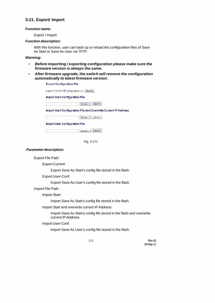
213 Rev.A118-May-11
3-21. Export/ Import
Function name:
Export / Import
Function description:
With this function, user can back up or reload the configuration files of SaveAs Start or Save As User via TFTP.
Warming:
Before importing / exporting configuration please make sure thefirmware version is always the same.
After firmware upgrade, the switch will remove the configurationautomatically to latest firmware version.
Fig. 3-171
Parameter description:
Export File Path:
Export Current:
Export Save As Start’s config file stored in the flash.
Export User-Conf:
Export Save As User’s config file stored in the flash.
Import File Path:
Import Start:
Import Save As Start’s config file stored in the flash.
Import Start and overwrite current IP Address:
Import Save As Start’s config file stored in the flash and overwritecurrent IP Address.
Import User-Conf:
Import Save As User’s config file stored in the flash.

Rev.A118-May-11
214
3-22. DiagnosticsThree functions, including Diagnostics, Loopback Test and Ping Test are
contained in this function folder for device self-diagnostics. Each of them will bedescribed in detail orderly in the following sections.
Diagnostics
Diagnostics
Ping Test
3-22-1 . DiagFunction name:
Diagnostics
Function description:
Diagnostics function provides a set of basic system diagnosis. It let usersknow that whether the system is health or needs to be fixed. The basic systemcheck includes EEPROM test, UART test, DRAM test and Flash test.
Fig. 3-172

215 Rev.A118-May-11
3-22-2 .Ping
Function name:
Ping Test
Function description:
Ping Test function is a tool for detecting if the target device is alive or notthrough ICMP protocol which abounds with report messages. The switchprovides Ping Test function to let you know that if the target device is availableor not. You can simply fill in a known IP address and then click <Ping> button.After a few seconds later, the switch will report you the pinged device is aliveor dead in the field of Ping Result.
Parameter description:
IP Address:
An IP address with the version of v4, e.g. 192.168.1.77.
Default Gateway:
IP address of the default gateway.
For more details, please see the section of IP address in Chapter 2.
Fig. 3-173

Rev.A118-May-11
216
3-23. MaintenanceThis chapter will introduce the reset and firmware upgrade function for the
firmware upgrade and key parameters change system maintenance requirements.
3-23-1 .Warm Restart
Function name:
Warm Restart
Function description:
We offer you many ways to reset the switch, including power up, hardwarereset and software reset. You can press the RESET button in the front panelto reset the switch. After upgrading software, changing IP configuration orchanging VLAN mode configuration, then you must reboot to have the newconfiguration taken effect. Here we are discussing is software reset for the“reboot” in the main menu.
Fig. 3-175
3-23-2 . Firmware upgrade
Function name:
Firmware Upgrade
Function description:
Click on <Browse> to select a specific SM8P-SFP firmware file from theWeb management PC, then click on <Upload> to confirm the upgradefirmware action. The new firmware will be uploaded into the switch and writeinto flash memory. You have to reboot the switch for new firmware take effectafter the firmware upgrade successfully.
Fig. 3-176

217 Rev.A118-May-11
3-24. LogoutYou can manually logout by performing Logout function. In the switch, it
provides another way to logout. You can configure it to logout automatically.
Function name:
Logout
Function description:
The switch allows you to logout the system to prevent other users from thesystem without the permission. If you do not logout and exit the browser, theswitch will automatically have you logout in five minutes. Besides this manuallylogout.
Parameter description:Logout:
Click on <Logout> to leave the web UI management function.
Fig. 3-177

Rev.A118-May-11
218
4. Operation of CLIManagement
4-1. CLI ManagementRefer to Chapter 2 for basic installation. The following description is the brief of thenetwork connection.
-- Locate the correct RJ-45 transform RS-232 cable with RJ-45 Console connector.Null modem cable comes with the management switch. Refer to the Appendix Bfor null modem cable configuration.
-- Attach the RJ-45 Console connector to the RJ-45 Console port connector on theManagement board.
-- Attach the other end of the RJ-45 transform RS-232 cable to an ASCII terminalemulator or PC Com-1, 2 port. For example, PC runs Microsoft WindowsHyperTerminal utility.
-- At “Com Port Properties” Menu, configure the parameters as below: (see the nextsection)
Baud rate 115200Stop bits 1Data bits 8Parity NFlow control none
4-1-1. LoginThe command-line interface (CLI) is a text-based interface. User can access
the CLI through either a direct serial connection to the device or a Telnet session.The default values of the managed switch are listed below:
Username: adminPassword: root
After you login successfully, the prompt will be shown as “#“ if you are thefirst login person and your authorization is administrator; otherwise it may show “$“.See the following two figures. The former means you behave as an administratorand have the access right of the system. As to the latter, it means you behave as aguest and are only allowed to view the system without the permission to do anysetting for this switch.
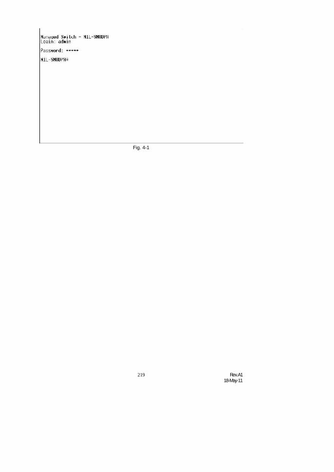
219 Rev.A118-May-11
Fig. 4-1

Rev.A118-May-11
220
4-2. Commands of CLITo see the commands of the mode, please input “?” after the prompt, then all
commands will be listed in the screen. All commands can be divided into twocategories, including global commands and local commands. Global commands canbe used wherever the mode you are. They are “exit”, “end”, “help”, “history”, “logout”,“save start”, “save user”, “restore default” and “restore user”. For more details,please refer to Section 4-2-1.
Command instructions reside in the corresponding modes are localcommands. The same command with the same command name may occur butperform totally different function in different modes. For example, “show” in IP modeperforms displaying the IP information; however, it performs displaying the systeminformation in system mode. For more details, please refer to Section 4-2-2.
Fig. 4-3

221 Rev.A118-May-11
4-2-1. Global Commands of CLI
end
Syntax:endDescription:Back to the top mode.When you enter this command, your current position would move to the top mode. Ifyou use this command in the top mode, you are still in the position of the top mode.Argument:None.Possible value:None.Example:SM8P-SFP# alarmSM8P-SFP(alarm)# eventsSM8P-SFP(alarm-events)#end
SM8P-SFP#
exit
Syntax:exitDescription:Back to the previous mode.When you enter this command, your current position would move back to theprevious mode. If you use this command in the top mode, you are still in the positionof the top mode.Argument:None.Possible value:None.Example:SM8P-SFP# trunkSM8P-SFP(trunk)# exit SM8P-SFP#

Rev.A118-May-11
222
help
Syntax:helpDescription:To show available commands.Some commands are the combination of more than two words. When you enter thiscommand, the CLI would show the complete commands. Besides, the commandwould help you classify the commands between the local commands and the globalones.Argument:None.Possible value:None.Example:SM8P-SFP# ipSM8P-SFP(ip)# helpCommands available:
------------<< Local commands >>------------set ip Set ip,subnet mask and gatewayset dns Set dnsenable dhcp Enable DHCP, and set dns auto or manualdisable dhcp Disable DHCPshow Show IP Configuration------------<< Global commands >>------------ exit
Back to the previous modeend Back to the top modehelp Show available commandshistory Show a list of previously run commandslogout Logout the systemsave start Save as start configsave user Save as user configrestore default Restore default configrestore user Restore user config
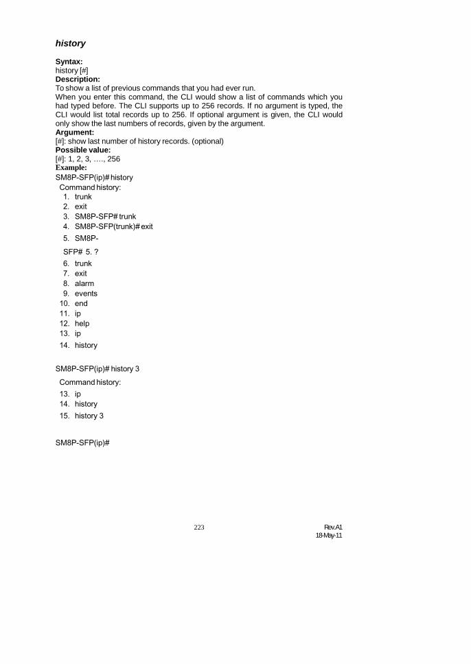
223 Rev.A118-May-11
history
Syntax:history [#]Description:To show a list of previous commands that you had ever run.When you enter this command, the CLI would show a list of commands which youhad typed before. The CLI supports up to 256 records. If no argument is typed, theCLI would list total records up to 256. If optional argument is given, the CLI wouldonly show the last numbers of records, given by the argument.Argument:[#]: show last number of history records. (optional)Possible value:[#]: 1, 2, 3, …., 256Example:SM8P-SFP(ip)# historyCommand history:1. trunk2. exit3. SM8P-SFP# trunk4. SM8P-SFP(trunk)# exit5. SM8P-SFP# 5. ?6. trunk7. exit8. alarm9. events
10. end11. ip12. help13. ip14. history
SM8P-SFP(ip)# history 3Command history:13. ip14. history15. history 3
SM8P-SFP(ip)#

Rev.A118-May-11
224
logout
Syntax:logoutDescription:When you enter this command via Telnet connection, you would logout the systemand disconnect. If you connect the system through direct serial port with RS-232cable, you would logout the system and be back to the initial login prompt when yourun this command.Argument:None.Possible value:None.Example:
SM8P-SFP# logout
restore default
Syntax:restore defaultDescription:When you use this function in CLI, the system will show you the information “Do youwant to restore the default IP address?(y/n)”. If you choose Y or y, the IP addresswill restore to default “192.168.1.77”. If you choose N or n, the IP address will keepthe same one that you had saved before.
If restoring default successfully, the CLI would prompt if reboot immediately or not. Ifyou press Y or y, the system would reboot immediately; otherwise, it would be backto the CLI system. After restoring default configuration, all the changes in the startupconfiguration would be lost. After rebooting, the entire startup configuration wouldreset to factory default.
Argument:None.Possible value:None.Example:
SM8P-SFP# restore defaultRestoring ...Restore Default Configuration Successfully Pressany key to reboot system.

225 Rev.A118-May-11
restore user
Syntax:restore userDescription:To restore the startup configuration as user defined configuration. If restoring defaultsuccessfully, the CLI would prompt if reboot immediately or not. If you press Y or y,the system would reboot immediately; others would back to the CLI system. Afterrestoring user-defined configuration, all the changes in the startup configurationwould be lost. After rebooting, the entire startup configuration would replace as userdefined one.Argument:None.Possible value:None.Example:
SM8P-SFP# restore user Restoring...Restore User Configuration Successfully Pressany key to reboot system.
save start
Syntax:save startDescription:To save the current configuration as the start one. When you enter this command,the CLI would save your current configuration into the non-volatile FLASH. If youwant the configuration still works after rebooting, save the configuration using thecommand ‘save stat’.Argument:None.Possible value:None.Example:
SM8P-SFP# save startSaving start...Save Successfully
SM8P-SFP#

Rev.A118-May-11
226
save user
Syntax:save userDescription:To save the current configuration as the user-defined configuration. When you enterthis command, the CLI would save your current configuration into the non-volatileFLASH as user-defined configuration.Argument:None.Possible value:None.Example:
SM8P-SFP# save userSaving user...Save Successfully
SM8P-SFP#
227 Rev.A118-May-11
4-2-2. Local Commands of CLI
802.1X
set maxReq
Syntax:set maxReq <port-range> <vlaue>Description:The maximum number of times that the state machine will retransmit an EAPRequest packet to the Supplicant before it times out the authentication session.Argument:<port range> : syntax 1,5-7, available from 1 to 8<value>: max-times , range 1-10Possible value:<port range> : 1 to 8<value>: 1-10, default is 2Example:
SM8P-SFP(802.1X)# set maxReq 2 2
set mode
Syntax:set mode <port-range> <mode>Description:To set up the 802.1X authentication mode of each port.Argument:<port range> : syntax 1,5-7, available from 1 to 8<mode>: set up 802.1X mode
0:disable the 802.1X function1:set 802.1X to Multi-host mode
Possible value:<port range> : 1 to 8<mode>: 0 or 1Example:SM8P-SFP(802.1X)# set mode 2 1 SM8P-SFP(802.1X)#
set port-control
Syntax:set port-control <port-range> <unauthorized| authorized| auto>Description:To set up 802.1X status of each port.Argument:<port range> : syntax 1,5-7, available from 1 to 8<authorized> : Set up the status of each port
0:ForceUnauthorized1:ForceAuthorized
Rev.A118-May-11
228
2:AutoPossible value:<port range> : 1 to 8<authorized> : 0, 1 or 2Example:SM8P-SFP(802.1X)# set port-control 2 2
set quietPeriod
Syntax:set quietPeriod <port-range> <value>Description:A timer used by the Authenticator state machine to define periods of time duringwhen it will not attempt to acquire a Supplicant.Argument:<port range> : syntax 1,5-7, available from 1 to 8<value> : timer , range 0-65535Possible value:<port range> : 1 to 8<value> : 0-65535, default is 60Example:SM8P-SFP(802.1X)# set quietPeriod 2 30
set reAuthEnabled
Syntax:set reAuthEnabled <port-range> <on | off >Description:A constant that define whether regular reauthentication will take place on this port.Argument:<port range> : syntax 1,5-7, available from 1 to 8<on | off > :
0:OFF Disable reauthentication1:ON Enable reauthentication
Possible value:<port range> : 1 to 8< on | off l> : 0 or 1, default is 1Example:SM8P-SFP(802.1X)# set reAuthEnabled 2 1
set reAuthMax
Syntax:set reAuthMax <port-range> <value>Description:The number of reauthentication attempts that are permitted before the portbecomes Unauthorized.Argument:<port range> : syntax 1,5-7, available from 1 to 8<value> : max. value , range 1-10

229 Rev.A118-May-11
Possible value:<port range> : 1 to 8<value> : 1-10, default is 2Example:SM8P-SFP(802.1X)# set reAuthMax 2 2
set reAuthPeriod
Syntax:set reAuthPeriod <port-range> <value>Description:A constant that defines a nonzero number of seconds between periodicreauthentication of the supplicant.Argument:<port range> : syntax 1,5-7, available from 1 to 8<value> : timer , range 1-65535Possible value:<port range> : 1 to 8<value> : 1-65535, default is 3600Example:SM8P-SFP(802.1X)# set reAuthPeriod 2 3600
set serverTimeout
Syntax:set serverTimeout <port-range> <value>Description:A timer used by the Backend Authentication state machine in order to determinetimeout conditions in the exchanges between the Authenticator and the Supplicantor Authentication Server. The initial value of this timer is either suppTimeout orserverTimeout, as determined by the operation of the Backend Authentication statemachine.Argument:<port range> : syntax 1,5-7, available from 1 to 8<value> : timer , range 1-65535Possible value:<port range> : 1 to 8<value> : 1-65535, default is 30Example:SM8P-SFP(802.1X)# set serverTimeout 2 30
set auth-server
Syntax:set auth-server <ip-address> <udp-port> <secret-key>Description:To configure the settings related with 802.1X Radius Server.Argument:<ip-address> : the IP address of Radius Server<udp-port> : the service port of Radius Server(Authorization port)

Rev.A118-May-11
230
<secret-key> : set up the value of secret-key, and the length of secret-key isfrom 1 to 31
Possible value:<udp-port > : 1~65535, default is 1812Example:SM8P-SFP(802.1X)# set auth-server 192.168.1.7715 1812 WinRadius
set suppTimeout
Syntax:set suppTimeout <port-range> <value>Description:A timer used by the Backend Authentication state machine in order to determinetimeout conditions in the exchanges between the Authenticator and the Supplicantor Authentication Server. The initial value of this timer is either suppTimeout orserverTimeout, as determined by the operation of the Backend Authentication statemachine.Argument:<port range> : syntax 1,5-7, available from 1 to 8<value> : timer , range 1-65535Possible value:<port range> : 1 to 8<value> : 1-65535, default is 30Example:SM8P-SFP(802.1X)# set suppTimeout 2 30
set txPeriod
Syntax:set txPeriod <port-range> <value>Description:A timer used by the Authenticator PAE state machine to determine when an EAPOLPDU is to be transmittedArgument:<port range> : syntax 1,5-7, available from 1 to 8<value> : timer , range 1-65535Possible value:<port range> : 1 to 8<value> : 1-65535, default is 30Example:SM8P-SFP(802.1X)# set txPeriod 2 30
show status
Syntax:show statusDescription:To display the mode of each port.Argument:None

231 Rev.A118-May-11
Possible value:NoneExample:SM8P-SFP(802.1X)# show statusPort Mode
====== ============1 Disable2 Multi-host3 Disable4 Disable5 Disable6 Disable
show port-config
Syntax:show port-config <port-range>Description:To display the parameter settings of each port.Argument:<port range> : syntax 1,5-7, available from 1 to 8Possible value:<port range> : 1 to 8Example:SM8P-SFP(802.1X)# show port-config 1, 2port 1) Mode : Disabledport control : Auto
reAuthMax : 2txPeriod : 30Quiet Period : 60reAuthEnabled : ONreAuthPeriod : 120max. Request : 2suppTimeout : 30serverTimeout : 30
port 2) Mode : Disabledport control : Auto
reAuthMax : 2txPeriod : 30Quiet Period : 60reAuthEnabled : ONreAuthPeriod : 120max. Request : 2

Rev.A118-May-11
232
suppTimeout : 30serverTimeout : 30

233 Rev.A118-May-11
show statistics
Syntax:show statistics <#>Description:To display the statistics of each port.Argument:<#> syntax 1,5-7, available from 1 to 8Possible value:<#> 1 to 8
:show server
Syntax:show serverDescription:Show the Radius server configurationArgument:NonePossible value:NoneExample:SM8P-SFP(802.1X)# show serverAuthentication Server
IP Address: 192.168.1.77UDP Port : 1812Secret Key : Radius
Accounting Server
IP Address: 192.168.1.77UDP Port : 1812Secret Key : Radius
account
add
Syntax:add <name>Description:To create a new guest user. When you create a new guest user, you must type inpassword and confirm password.Argument:<name> : new account name

Rev.A118-May-11
234
Possible value:A string must be at least 5 character.Example:

235 Rev.A118-May-11
SM8P-SFP(account)# add aaaaaPassword:Confirm Password:SM8P-SFP(account)#
del
Syntax:del <name>Description:To delete an existing account.Argument:<name> : existing user accountPossible value:None.Example:SM8P-SFP(account)# del aaaaaAccount aaaaa deleted
modify
Syntax:modify <username>Description:To change the username and password of an existing account.Argument:<name> : existing user accountPossible value:None.Example:SM8P-SFP(account)# modify aaaaausername/password: the length is from 5 to 15. Currentusername (aaaaa):bbbbbNew password:Confirm password:Username changed successfully.Password changed successfully.
show
Syntax:showDescription:To show system account, including account name and identity.Argument:

Rev.A118-May-11
236
None.Possible value:None.

237 Rev.A118-May-11
Example:SM8P-SFP(account)#showAccount Name Identity----------------- ---------------admin Administratorguest guest
HTTPs
set state
Syntax:set state <0|1>Description:To set SSL function for secure encryption web manage traffic.Argument:<0/1> : 0: disable 1: enablePossible value:<0/1> : 0: disable 1: enable, default is 0Example:
SM8P-SFP(https)# set state 1 SM8P-SFP(https)#
set redirect
Syntax:set redirect <0|1>Description:To set SSL function for secure encryption web manage traffic and redirectautomatically to Https login page of IE browser.Argument:<0/1> : 0: disable 1: enablePossible value:<0/1> : 0: disable 1: enable, default is 0Example:SM8P-SFP(https)# set redirect 1 SM8P-SFP(https)#
Show
Syntax:ShowDescription:To display the SSL setting statusr.Argument:NonePossible value:

Rev.A118-May-11
238
NoneExample:SM8P-SFP(https)#showState : EnabledRedirect: EnabledSM8P-SFP(https)#
account
add
Syntax:add <name>Description:To create a new guest user. When you create a new guest user, you must type inpassword and confirm password.Argument:<name> : new account namePossible value:A string must be at least 5 character.Example:SM8P-SFP(account)# add aaaaaPassword:Confirm Password:SM8P-SFP(account)#
del
Syntax:del <name>Description:To delete an existing account.Argument:<name> : existing user accountPossible value:None.Example:SM8P-SFP(account)# del aaaaaAccount aaaaa deleted
modify
Syntax:modify <username>Description:To change the username and password of an existing account.Argument:<name> : existing user account

239 Rev.A118-May-11
Possible value:None.Example:SM8P-SFP(account)# modify aaaaausername/password: the length is from 5 to 15. Currentusername (aaaaa):bbbbbNew password:Confirm password:Username changed successfully.Password changed successfully.
show
Syntax:showDescription:To show system account, including account name and identity.Argument:None.Possible value:None.Example:SM8P-SFP(account)#showAccount Name Identity----------------- ---------------admin Administratorguest guest
acl
ace
Syntax:ace <index>Description:To display the ace configuration.Argument:<index> : the access control rule index valuePossible value:None.Example:SM8P-SFP(acl)# ace 2

Rev.A118-May-11
240
index: 2 rule:switch vid:any

241 Rev.A118-May-11
tag_prio: anydmac: anyframe type: arparp type: Request/Reply (opcode): anysource ip: anydestination ip: any ARPflagARP SMAC Match: anyRARP DMAC Match: anyIP/Ethernet Length: any IP:anyEthernet: anyaction: 1rate limiter: 0copy port: 0

Rev.A118-May-11
242
action
Syntax:action <port> <permit|deny> <rate_limiter> <port copy>Description:To set the access control per port as packet filter action rule.Argument:<port> : 1-8<permit/deny>: permit: 1, deny: 0<rate_limiter>: 0-16 (0:disable)<port copy> : 0-8 (0:disable)Possible value:<port> : 1-8<permit/deny>: 0-1<rate_limiter>: 0-16<port copy> : 0-8Example:SM8P-SFP(acl)# action 5 0 2 2 SM8P-SFP(acl)#showport policy id action rate limiter port copy counter a class map.. .. ……. …. … ..5 1 deny 2 2
rate limiter rate(pps)------------ ------------
1 12 13 14 15 1
…… ……SM8P-SFP(acl)#
delete
Syntax:delete <index>Description:To delete the ACE ( Access Control Entry) configuration on the switch.Argument:<index> : the access control rule index valuePossible value:None.Example:SM8P-SFP(acl)# delete 1 SM8P-SFP(acl)#
243 Rev.A118-May-11
move
Syntax:move <index1> <index2>Description:To move the ACE ( Access Control Entry) configuration between index1 and index2..Argument:None.Possible value:None.Example:SM8P-SFP(account)# move 1 2
policy
Syntax:policy <policy> <ports>Description:To set acl port policy on switchArgument:<policy> : 1-8<ports> : 1-8Possible value:<policy> : 1-8<ports> : 1-8Example:SM8P-SFP(acl)# policy 3 10 SM8P-SFP(acl)#
ratelimiter
Syntax:ratelimiter <id> <rate>Description:To set access control rule with rate limiter on switchArgument:<id> : 1-16<rate> : 1,2,4,8,16,32,64,128,256,512,1000,2000, 4000,8000,
16000,32000,64000,128000,256000,512000,1024000Possible value:<id> : 1-16<rate> : 1,2,4,8,16,32,64,128,256,512,1000,2000, 4000,8000,
16000,32000,64000,128000,256000,512000,1024000Example:SM8P-SFP(acl)# ratelimiter 3 16000 SM8P-SFP(acl)#

Rev.A118-May-11
240
set
Syntax:set [<index>] [<next index>]
[switch | (port <port>) | (policy <policy>)][<vid>] [<tag_prio>] [<dmac_type>][(any) |(etype [<etype>] [<smac>]) |(arp [<arp type>] [<opcode>]
(any | [<source ip>] [<source ip mask>])(any | [<destination ip>] [<destination ip mask>])[<source mac>] [<arp smac match flag>][<raro dmac match flag>] [<ip/ethernet length flag>][<ip flag>] [<ethernet flag>]) |
(ip [(<source ip> <source ip mask>) | any][(<destination ip> <destination ip mask>) | any][<ip ttl>] [<ip fragment>] [<ip option>][(icmp <icmp type> <icmp code>) |(udp <source port range> <destination port range>) |(tcp <source port range> <destination port range>
<tcp fin flag> <tcp syn flag> <tcp rst flag><tcp psh flag> <tcp ack flag> <tcp urg flag>) |
(other <ip protocol value>) |(any)]
][<action>] [<rate limiter>] [<port copy>]
Description:To set access control entry on switchArgument:
Possible value:
Example:
show
Syntax:showDescription:To show all access control entry setting on switchArgument:nonePossible value:noneExample:SM8P-SFP(acl)# showport policy id action rate limiter port copy counter a class map.. .. ……. …. … ..5 1 deny 2 2

241 Rev.A118-May-11
rate limiter rate(pps)

Rev.A118-May-11
242
------------ ------------1 12 13 14 15 1
…… ……SM8P-SFP(acl)#
alarm
<<email>>
del mail-address
Syntax:del mail-address <#>Description:To remove the configuration of E-mail address.Argument:<#>: email address number, range: 1 to 6Possible value:<#>: 1 to 6Example:SM8P-SFP(alarm-email)# del mail-address 2
del server-user
Syntax:del server-userDescription:To remove the configuration of server, user account and password.Argument:None.Possible value:None.Example:SM8P-SFP(alarm-email)# del server-user
set mail-address
Syntax:set mail-address <#> <mail address>Description:To set up the email address.Argument:<#> :email address number, range: 1 to 6

243 Rev.A118-May-11
<mail address>:email addressPossible value:<#>: 1 to 6Example:SM8P-SFP(alarm-email)# set mail-address 1 [email protected]
set server
Syntax:set server <ip>Description:To set up the IP address of the email server.Argument:<ip>:email server ip address or domain namePossible value:None.Example:SM8P-SFP(alarm-email)# set server 192.168.1.6
set user
Syntax:set user <username>Description:To set up the account and password of the email server.Argument:<username>: email server account and passwordPossible value:None.Example:SM8P-SFP (alarm-email)# set user admin
show
Syntax:showDescription:To display the configuration of e-mail.Argument:None.Possible value:None.Example:SM8P-SFP(alarm-email)#showMail Server : 192.168.1.6Username : adminPassword : ****************Email Address 1: [email protected] Address 2:
Rev.A118-May-11
244
Email Address 3:Email Address 4:Email Address 5:Email Address 6:
<<events>>
del all
Syntax:del all <range>Description:To disable email and trap of events.Argument:<range>:del the range of events, syntax 1,5-7Possible value:<range>: 1~24Example:SM8P-SFP(alarm-events)# del all 1-3
del email
Syntax:del email <range>Description:To disable the email of the events.Argument:<range>:del the range of email, syntax 1,5-7Possible value:<range>: 1~24Example:SM8P-SFP(alarm-events)# del email 1-3
del trap
Syntax:del trap <range>Description:To disable the trap of the events.Argument:<range>:del the range of trap, syntax 1,5-7Possible value:<range>: 1~24Example:SM8P-SFP(alarm-events)# del trap 1-3

245 Rev.A118-May-11
set all
Syntax:set all <range>Description:To enable email and trap of events.Argument:<range>:set the range of events, syntax 1,5-7Possible value:<range>: 1~24Example:SM8P-SFP(alarm-events)# set all 1-3
set email
Syntax:set email <range>Description:To enable the email of the events.Argument:<range>:set the range of email, syntax 1,5-7Possible value:<range>: 1~24Example:SM8P-SFP(alarm-events)# set email 1-3
set trap
Syntax:set trap <range>Description:To enable the trap of the events.Argument:<range>:set the range of trap, syntax 1,5-7Possible value:<range>: 1~24Example:SM8P-SFP(alarm-events)# set trap 1-3
show
Syntax:showDescription:To display the configuration of alarm event.Argument:None.Possible value:None.

Rev.A118-May-11
246
Example:SM8P-SFP(alarm-events)#show
Events Email Trap-----------------------------------------1 Cold Start v2 Warm Start v3 Link Down v4 Link Up v5 Authentication Failure v6 Login7 Logout8 Module Inserted9 Module Removed10 Dual MediaSwapped 11 LoopingDetected12 STP Disabled13 STP Enabled14 STP TopologyChanged 15 LACPDisabled16 LACP Enabled17 LACP Member Added18 LACP Aggregates Port Failure19 GVRP Disabled20 GVRP Enabled21 VLAN Disabled22 Port-based Vlan Enabled23 Tag-based Vlan Enabled24 IP MAC Binding Enabled25 IP MAC Binding Disabled26 IP MAC Binding Client Authenticate error 27IP MAC Binding Server Authenticate error
show (alarm)
Syntax:showDescription:The Show for alarm here is used to display the configuration of Events, or E-mail.Argument:None.

247 Rev.A118-May-11
Possible value:None.Example:SM8P-SFP(alarm)# show events SM8P-SFP(alarm)# show email

Rev.A118-May-11
248
autologout
autologout
Syntax:autologout <time>Description:To set up the timer of autologout.Argument:<time>: range 1 to 3600 seconds, 0 for autologout off, current setting is 180seconds.Possible value:<time>: 0,1-3600Example:SM8P-SFP# autologout 3600Set autologout time to 3600 seconds
config-file
export
Syntax:export <current | user> < ip address>Description:To run the export function.Argument:< Usage> set up current or user< ip address> the TFTP server ip addressPossible value:noneExample:SM8P-SFP(config-file)# export current 192.168.1. 63 Exportsuccessful.
import
Syntax:import <current | user> < ip address>Description:To run the import start function.Argument:NonePossible value:NoneExample:SM8P-SFP(config-file)# import current 192.168.1.63 Importsuccessful.

249 Rev.A118-May-11
firmware
Upgrade
Syntax:upgrade <ip_address> <file_path>Description:To set up the image file that will be upgraded.Argument:< ip address> : TFTP server ip address<filepath>: upgrade file pathPossible value:< ip address> : TFTP server ip address<filepath>: upgrade file pathExample:SM8P-SFP(firmware)# upgrade 192.168.2.4 fgs2924R_SM8P-SFP_v2.03.img
gvrp
set state
Syntax:set state < 0 | 1>Description:To disable/ enable the gvrp function.Argument:0 : disable the gvrp function1 : enable the gvrp functionPossible value:0 : disable the gvrp function1 : enable the gvrp functionExample:SM8P-SFP(gvrp)# set state 1
group applicant
Syntax:group applicant <vid> <port> < 0 | 1>Description:To enter any of gvrp group for changing gvrp group setting. You can change theapplicant or registrar mode of existing gvrp group per port.Argument:<vid>: enter which gvrp group you had created, using value is vid. Available range:1 to 4094<port>: 1 to 8< 0 | 1> :Possible value:<vid>: 1~4094<port>: 1 to 8

Rev.A118-May-11
250
Example:SM8P-SFP(gvrp)# group applicant 2 5 0GVRP group informationCurrent Dynamic Group Number: 1VID Member Port------------------------------------------------------ 2 5
set applicant
Syntax:set applicant <port> < 0 | 1 >Description:To set default applicant mode for each port.Argument:<port>: port range, syntax 1,5-7, available from 1 to 8<0>: set applicant as normal mode<1>: set applicant as non-participant modePossible value:<port>: 1 to 8< 0 | 1 >: normal or non-participantExample:SM8P-SFP(gvrp)# set applicant 1-8 non-participant
set registrar
Syntax:set registrar <port> < 0 | 1 | 2>Description:To set default registrar mode for each port.Argument:<port>: port range, syntax 1,5-7, available from 1 to 8<0>: set registrar as normal mode<1>: set registrar as fixed mode<2>: set registrar as forbidden modePossible value:<range>: 1 to 8< 0 | 1 | 2>: normal or fixed or forbiddenExample:SM8P-SFP(gvrp)# set registrar 1-5 fixed
set restricted
Syntax:set restricted <port> <0 | 1 | 2>Description:To set the restricted mode for each port.

251 Rev.A118-May-11
Argument:<port>: port range, syntax 1,5-7, available from 1 to 8<0>: set restricted normal<1>: set restricted fixed<2>: set restricted forbiddenPossible value:<port>: 1 to 8< 0| 1| 2>: normal, fixed or forbiddenExample:SM8P-SFP(gvrp)# set restricted 1-8 1 SM8P-SFP(gvrp)# show configGVRP state: EnablePort Join Time Leave Time LeaveAll Time Applicant Registrar Restricted
---- --------- ---------- ------------- --------------- --------- ----------1 20 60 1000 Normal Normal Enable2 20 60 1000 Normal Normal Enable3 20 60 1000 Normal Normal Enable4 20 60 1000 Normal Normal Enable5 20 60 1000 Normal Normal Enable6 20 60 1000 Normal Normal Enable7 20 60 1000 Normal Normal Enable8 20 60 1000 Normal Normal Enable
set timer
Syntax:set timer <port> <JoinTime> <leaveTime> <leaveAllTime>Description:To set gvrp join time, leave time, and leaveall time for each port.Argument:<port> : port range, syntax 1,5-7, available from 1 to 8<JoinTime>: join timer, available from 20 to 100<LeaveTime>: leave timer, available from 60 to 300<LeaveAllTime>: leaveall timer, available from 1000 to 5000Leave Time must equal double Join Time at least.Possible value:<port> : 1 to 8<JoinTime>: 20 to 100<LeaveTime>: 60 to 300<LeaveAllTime>: 1000 to 5000Example:SM8P-SFP(gvrp)# set timer 2-8 25 80 2000
show
Syntax:showDescription:To display the gvrp configuration.Argument:None

Rev.A118-May-11
250
Possible value:NoneExample:SM8P-SFP(gvrp)# showGVRP state: EnablePort Join Time Leave Time LeaveAll Time Applicant Registrar Restricted---- --------- ---------- ------------- --------------- --------- ----------
1 20 60 1000 Normal Normal Disable2 25 80 2000 Normal Normal Disable3 25 80 2000 Normal Normal Disable4 25 80 2000 Normal Normal Disable5 25 80 2000 Normal Normal Disable6 25 80 2000 Normal Normal Disable7 25 80 2000 Normal Normal Disable8 25 80 2000 Normal Normal Disable
counter
Syntax:counter <port>Description:To display the counter number of the port.Argument:<port>: port numberPossible value:<port>: available from 1 to 8Example:SM8P-SFP(gvrp)# counter 2
Received
Total GVRP Packets 0Invalid GVRP Packets 0LeaveAll message 0
JoinEmpty message 0JoinIn message 0LeaveEmpty message 0Empty message 0
Transmitted
Total GVRP Packets 0Invalid GVRP Packets 0
LeaveAll message 0JoinEmpty message 0JoinIn message 0
LeaveEmpty message 0Empty message 0

251 Rev.A118-May-11
group grpinfo
Syntax:group grpinfo <vid>Description:To show the gvrp group.Argument:<vid>: To set the vlan id from 1 to 4094Possible value:<vid>: 1 to 4094Example:SM8P-SFP(gvrp)# group grpinfo 2GVRP group informationVID Member Port-----------------------------------------------------
hostname
hostname
Syntax:hostname <name>Description:To set up the hostname of the switch.Argument:<name>: hostname, max. 40 characters.Possible value:<name>: hostname, max. 40 characters.Example:SM8P-SFP# hostname Company
Company#
igmp
set drp
Syntax:set drp <port >Description:Set router ports to disable.Argument:<port >: syntax 1,5-7, available from 1 to 8Possible value:<port >: 1 to 8Example:SM8P-SFP(igmp)# set drp 1- 8

Rev.A118-May-11
252
set erp
Syntax:set erp <port>Description:Set router ports to enableArgument:<port>: syntax 1,5-7, available from 1 to 8Possible value:<port>: 1 to 8Example:SM8P-SFP(igmp)# set erp 1
set flood
Syntax:set flood <state>Description:To set up disable / enable unregister ipmc flooding.Argument:<state>: 0:disable, 1:enablePossible value:<state>: 0,or 1Example:SM8P-SFP(igmp)# set flood 1
show gm
Syntax:show gmDescription:To display group memebership.Argument:None.Possible value:None.Example:SM8P-SFP(igmp)# show gm
show igmpp
Syntax:show igmppDescription:To display igmp proxy settingArgument:None.Possible value:

253 Rev.A118-May-11
None.Example:SM8P-SFP(igmp)# show igmpp
IP
disable dhcp
Syntax:disable dhcpDescription:To disable the DHCP function of the system.Argument:NonePossible value:NoneExample:SM8P-SFP(ip)# disable dhcp
enable dhcp
Syntax:enable dhcp <manual|auto>Description:To enable the system DHCP function and set DNS server via manual or auto mode.Argument:<manual|auto> : set dhcp by using manual or auto mode.Possible value:<manual|auto> : manual or autoExample:SM8P-SFP(ip)# enable dhcp manual
set dns
Syntax:set dns <ip>Description:To set the IP address of DNS server.Argument:<ip> : dns ip addressPossible value:168.95.1.1Example:SM8P-SFP (ip)# set dns 168.95.1.1

Rev.A118-May-11
254
set ip
Syntax:set ip <ip> <mask> <gateway>Description:To set the system IP address, subnet mask and gateway.Argument:<ip> : ip address<mask> : subnet mask<gateway> : default gatewayPossible value:<ip> : 192.168.1.2 or others<mask> : 255.255.255.0 or others<gateway> : 192.168.1.253 or othersExample:SM8P-SFP(ip)# set ip 192.168.1.2 255.255.255.0 192.168.1.253
show
Syntax:showDescription:To display the system’s DHCP function state, IP address, subnet mask, defaultgateway, DNS mode, DNS server IP address and current IP address.Argument:NonePossible value:NoneExample:SM8P-SFP(ip)# show
DHCP : DisableIP Address : 192.168.2.237Current IP Address : 192.168.2.237Subnet mask : 255.255.255.0Gateway : 192.168.2.252DNS Setting : ManualDNS Server : 168.95.1.1

255 Rev.A118-May-11
ip_mac_binding
set entry
Syntax:set entry < 0 | 1> < mac> < ip> < port no> < vid>Description:To set ip mac binding entryArgument:< 0 | 1> : 0 : Client , 1: Server<mac> : mac address< ip > : ip address< port > : syntax 1,5-7, available from 1 to 8< vid > : vlan id, 1 to 4094Possible value:< 0 | 1> : 0 : Client , 1: Server<mac> : format: 00-02-03-04-05-06< ip > : ip address< port > : 1 to 8< vid > : 1 to 4094
Example:SM8P-SFP(ip_mac_binding)# set entry 1 00-11-2f-de-7b-a9 192.168.2.2 1 1
delete ip
Syntax:delete ip < 0 | 1> <ip>Description:Delete ip mac binding entry by ip.Argument:<0 | 1> : 0 : client, 1: server<ip> : ip addressPossible value:NoneExample:SM8P-SFP(ip_mac_binding)# delete ip 1 192.168.2.2
set state
Syntax:showDescription:To display the mac alias entry.Argument:NonePossible value:NoneExample:

Rev.A118-May-11
256
SM8P-SFP(mac-table-alias)#showMAC Alias List
MAC Address Alias----- ----------------- ---------------- 1) 00-02-03-04-05-06 aaa2) 00-33-03-04-05-06 ccc3) 00-44-33-44-55-44 www
loop-detection
disable
Syntax:disable <#>Description:To disable switch ports the loop detection function.Argument:<#> : set up the range of the ports to search for, syntax 1,5-7, available form 1 to 8Possible value:<#> :1 to 8Example:SM8P-SFP(loop-detection)# disable 1-24 SM8P-SFP(loop-detection)#showDetection Port Locked Port
Port Status Port Status---------------------------------
1 Disable 1 Normal2 Disable 2 Normal3 Disable 3 Normal4 Disable 4 Normal5 Disable 5 Normal6 Disable 6 Normal7 Disable 7 Normal8 Disable 8 Normal
enable
Syntax:enable <#>Description:To enable switch ports the loop detection function.Argument:<#> : set up the range of the ports to search for, syntax 1,5-7, available form 1 to 8Possible value:<#> :1 to 8Example:SM8P-SFP(loop-detection)# enable 1-8 SM8P-

257 Rev.A118-May-11
SFP(loop-detection)#show

Rev.A118-May-11
258
Detection Port Locked PortPort Status Port Status
---------------------------------1 Enable 1 Normal2 Enable 2 Normal3 Enable 3 Normal4 Enable 4 Normal5 Enable 5 Normal6 Enable 6 Normal7 Enable 7 Normal8 Enable 8 Normal
Resume
Syntax:resume <#>Description:To resume locked ports on switch.Argument:<#> : set up the range of the ports to search for, syntax 1,5-7, available form 1 to 8Possible value:<#> :1 to 8Example:SM8P-SFP (loop-detection)# resume 1-24 SM8P-SFP (loop-detection)# showDetection Port Locked Port
Port Status Port Status---------------------------------
1 Enable 1 Normal2 Enable 2 Normal3 Enable 3 Normal4 Enable 4 Normal5 Enable 5 Normal6 Enable 6 Normal7 Enable 7 Normal8 Enable 8 Normal
Resume
Syntax:resume <#>Description:To resume locked ports on switch.Argument:<#> : set up the range of the ports to search for, syntax 1,5-7, available form 1 to 8Possible value:
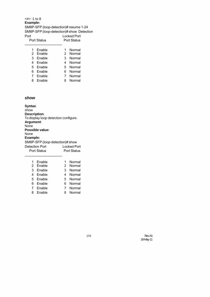
259 Rev.A118-May-11
<#> :1 to 8Example:SM8P-SFP (loop-detection)# resume 1-24SM8P-SFP (loop-detection)# show DetectionPort Locked Port
Port Status Port Status---------------------------------
1 Enable 1 Normal2 Enable 2 Normal3 Enable 3 Normal4 Enable 4 Normal5 Enable 5 Normal6 Enable 6 Normal7 Enable 7 Normal8 Enable 8 Normal
show
Syntax:showDescription:To display loop detection configure.Argument:NonePossible value:NoneExample:SM8P-SFP (loop-detection)# showDetection Port Locked Port
Port Status Port Status---------------------------------
1 Enable 1 Normal2 Enable 2 Normal3 Enable 3 Normal4 Enable 4 Normal5 Enable 5 Normal6 Enable 6 Normal7 Enable 7 Normal8 Enable 8 Normal

Rev.A118-May-11
260
LLDP
<<set clear>>
set
Syntax:set clearDescription:To set clear LLDP entry.Argument:None
Possible value:<clear> : set clear LLDP<clear counter> : set clear LLDP counterExample:SM8P-SFP(lldp)# set clear SM8P-SFP(lldp)#
set mode
Syntax:set mode <mode> <range>Description:To set LLDP modeArgument:tx and rx = 1tx only = 2rx only = 3disabled = 0port range syntax : 1,5-7, available from 1 to 8Possible value:<Port range> : 1 to 8Example:SM8P-SFP(lldp)# set mode 1 15 SM8P-SFP(lldp)#
set notification
Syntax:set notification <state> <range>Description:To set LLDP notificationArgument:enable = 1disable = 2Possible value:<Port range> : syntax : 1,5-7, available from 1 to 8Example:


Rev.A118-May-11
260
SM8P-SFP(lldp)# set notification 1 5 SM8P-SFP(lldp)#
set reInitDelay
Syntax:set reInitDelay <time>Description:To set LLDP reInitDelay timeArgument:<Time> : from 1 to 10 second(s)Possible value:<Time> : from 1 to 10 second(s)Example:SM8P-SFP(lldp)# set reInitDelay 5 SM8P-SFP(lldp)#
set tlv
Syntax:set tlv <0> <1> <2> <3> <4> <range>Description:To set disable/enable lldp tlvArgument:Port Description: bit 0System Name: bit 1System Description: bit 2System Capabilities: bit 3Management Address: bit 4port range syntax : 1,5-7, available from 1 to 8Possible value:<Port Range> : syntax : 1,5-7, available from 1 to 8Example:SM8P-SFP(lldp)# set tlv test SM8P-SFP swtich 5 122 5 SM8P-SFP(lldp)#
set txDelay
Syntax:set txDelay <time>Description:To set lldp txdelayArgument:<time>: from 1 to 8192 second(s)Possible value:<time>: from 1 to 8192 second(s)Example:SM8P-SFP(lldp)# set txDelay 500 SM8P-SFP(lldp)#

261 Rev.A118-May-11
set txHold
Syntax:set txHold <time>Description:To set lldp txHoldArgument:<time>: from 2 to 10 second(s)Possible value:<time>: from 2 to 10 second(s)Example:SM8P-SFP(lldp)# set txHold 5 SM8P-SFP(lldp)#
set txInterval
Syntax:set txInterval <time>Description:To set lldp txIntervalArgument:<time>: from 5 to 32768 second(s)Possible value:<time>: from 5 to 32768 second(s)Example:SM8P-SFP(lldp)# set txInterval 5 SM8P-SFP(lldp)#
show config
Syntax:Show configDescription:To display LLDP ConfigurationArgument:NonePossible value:noneExample:SM8P-SFP(lldp)# show config
LLDP Global Configuation
LLDP Transmit Interval [30] : 5 LLDPHold time Multiplier [4] : 5 LLDP DelayInterval [2] : 1LLDP Reinit Interval [2] : 5

Rev.A118-May-11
262
Port AdminStatus NotificationEnabled---- ----------- -------------------
1 Disable False2 Disable False3 Disable False4 Disable False5 Disable True6 Disable False7 Disable False8 Disable False
LLDP Notification Interval [5] : 500 LLDP
Port Configuation
SM8P-SFP(lldp)#
show detail counter
Syntax:show detail-counter <port>Description:To display LLDP detail counterArgument:<port>: 1,5-9, available from 1 to 8Possible value:<port>: 1,5-9, available from 1 to 8Example:
SM8P-SFP(lldp)# show detail-counter 15 LLDPPort Statistics Detail
Port Name : 15Frames Discarded : 0
Frames Invalid : 0Frames REceived : 0Frames Sent : 0 TLVsUnrecognized : 0 TLVsDiscard : 0 NeighborAgeouts : 0 SM8P-SFP(lldp)#
show local-device

263 Rev.A118-May-11
Syntax:show local-deviceDescription:To display LLDP local deviceArgument:None
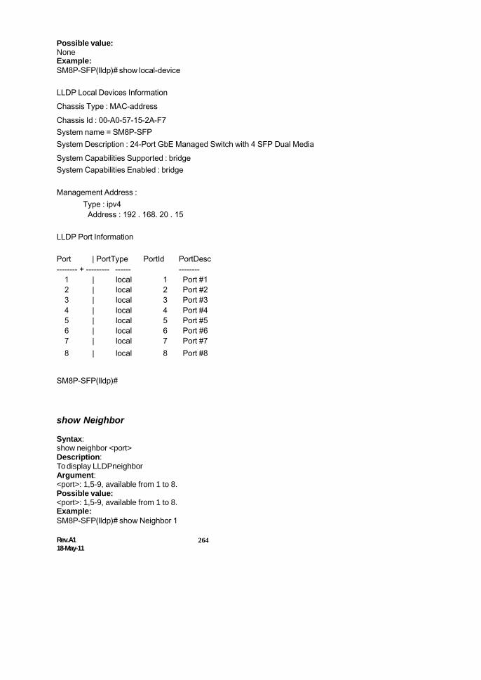
Rev.A118-May-11
264
Possible value:NoneExample:SM8P-SFP(lldp)# show local-device
LLDP Local Devices InformationChassis Type : MAC-addressChassis Id : 00-A0-57-15-2A-F7System name = SM8P-SFPSystem Description : 24-Port GbE Managed Switch with 4 SFP Dual MediaSystem Capabilities Supported : bridgeSystem Capabilities Enabled : bridge
Management Address :Type : ipv4
Address : 192 . 168. 20 . 15
LLDP Port Information
Port | PortType PortId PortDesc-------- + --------- ------ --------
1 | local 1 Port #12 | local 2 Port #23 | local 3 Port #34 | local 4 Port #45 | local 5 Port #56 | local 6 Port #67 | local 7 Port #78 | local 8 Port #8
SM8P-SFP(lldp)#
show Neighbor
Syntax:show neighbor <port>Description:To display LLDPneighborArgument:<port>: 1,5-9, available from 1 to 8.Possible value:<port>: 1,5-9, available from 1 to 8.Example:SM8P-SFP(lldp)# show Neighbor 1

265 Rev.A118-May-11
LLDP Remote Devices Information SM8P-
SFP(lldp)#

Rev.A118-May-11
266
show port-config
Syntax:show port-config <port>Description:To display LLDPport configArgument:<port>: 1,5-9, available from 1 to 8.Possible value:<port>: 1,5-9, available from 1 to 8.Example:SM8P-SFP(lldp)# show port-config 5
LLDP Port Configuration Detail
Port : 5AdminStatus [Tx_Rx] : Disable
NotificationEnabled [False] : True
TLVs Advertised :SM8P-SFP(lldp)#SM8P-SFP(lldp)#
show stats
Syntax:show statsDescription:To display LLDP statsArgument:NonePossible value:NoneExample:SM8P-SFP(lldp)# show stats
LLDP Device StatisticsNeighbor Entries List Last Updated : 5850 sec. ago NewNeighbor Entries Count : 0Neighbor Entries Deleted Count : 0Neighbor Entries Dropped Count : 0Neighbor Entries AgeOut Count : 0
LLDP Port Statistics

267 Rev.A118-May-11
Tx Rx Rx Rx TLV TLVPort Frames Frames Errors Discards Discards Unknown
Aged
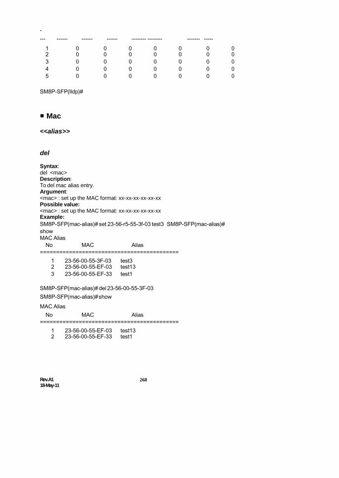
Rev.A118-May-11
268
---- ------ ------ ------ -------- -------- ------- -----
1 0 0 0 0 0 0 02 0 0 0 0 0 0 03 0 0 0 0 0 0 04 0 0 0 0 0 0 05 0 0 0 0 0 0 0
SM8P-SFP(lldp)#
Mac
<<alias>>
del
Syntax:del <mac>Description:To del mac alias entry.Argument:<mac> : set up the MAC format: xx-xx-xx-xx-xx-xxPossible value:<mac> : set up the MAC format: xx-xx-xx-xx-xx-xxExample:SM8P-SFP(mac-alias)# set 23-56-r5-55-3f-03 test3 SM8P-SFP(mac-alias)#showMAC Alias
No MAC Alias===========================================
1 23-56-00-55-3F-03 test32 23-56-00-55-EF-03 test133 23-56-00-55-EF-33 test1
SM8P-SFP(mac-alias)# del 23-56-00-55-3F-03SM8P-SFP(mac-alias)#showMAC Alias
No MAC Alias===========================================
1 23-56-00-55-EF-03 test132 23-56-00-55-EF-33 test1

269 Rev.A118-May-11
set
Syntax:set <mac> < alias>Description:To set mac alias entry.Argument:<mac> : mac address, xx-xx-xx-xx-xx-xx<alias> : mac alias name, max 15 charactersPossible value:<mac> : set up the MAC format: xx-xx-xx-xx-xx-xx<alias> : mac alias name, max 15 charactersExample:SM8P-SFP(mac-alias)# set 23-56-r5-55-3f-03 test3 SM8P-SFP(mac-alias)#showMAC Alias
No MAC Alias===========================================
1 23-56-00-55-3F-03 test32 23-56-00-55-EF-03 test133 23-56-00-55-EF-33 test1
show
Syntax:showDescription:To display mac alias entry.Argument:NonePossible value:noneExample:SM8P-SFP(mac-alias)#showMAC Alias
No MAC Alias===========================================
1 23-56-00-55-3F-03 test32 23-56-00-55-EF-03 test133 23-56-00-55-EF-33 test1
<<mac-table>>
flush
Syntax:flushDescription:To del dynamic mac entry.

Rev.A118-May-11
270
Argument:nonePossible value:noneExample:SM8P-SFP(mac-mac-table)#flush SM8P-SFP(mac-mac-table)#show
No Type VLAN MAC Port Members-------------------------------------------------------------------------------
1 Static 1 FF-FF-FF-FF-FF-FF 1,2,3,4,5,6,7,8
show
Syntax:showDescription:To show all mac table informaion.Argument:nonePossible value:noneExample:SM8P-SFP(mac-mac-table)#show
No Type VLAN MAC Port Members-------------------------------------------------------------------------------
1 Static 1 FF-FF-FF-FF-FF-FF 1,2,3,4,5,6,7,8
<<maintenance>>
set age-time
Syntax:set age-time <#>Description:To set mac table age out time of dynamic learning mac.Argument:<#>: age-timer in seconds, 0, 10 1000000. The value zero disables agingPossible value:<#>: 0, 10 to 1000000.Example:SM8P-SFP(mac-table-maintain)# set age-time 300 SM8P-SFP(mac-maintenance)#showE api_ai 26/vtss_

271 Rev.A118-May-11
Aging Configuration: Enter into sta

Rev.A118-May-11
272
Age time: 300mode
MAC Table LearningPort Learning Mode-<< Global commands >
2 Auto3 Auto4 Auto5 Auto6 Auto7 Auto
set learning
Syntax:set learning <range> <auto|disable|secure>Description:To set mac table learning.Argument:<range syntax> : 1,5-7, available from 1 to 8<auto >: auto learning<disable >: disable learning<secure >: learn frames are discardedPossible value:<range syntax> : 1,5-7, available from 1 to 8<auto >: auto learning<disable >: disable learning<secure >: learn frames are discarded.Example:SM8P-SFP(mac-table-maintain)# set learning 1-24 auto SM8P-SFP(mac-maintenance)#showE api_ai 26/vtss_
Aging Configuration: Enter into staAge time: 300mode
MAC Table LearningPort Learning Mode-<< Global commands >
2 Auto3 Auto4 Auto5 Auto6 Auto7 Auto8 Auto

273 Rev.A118-May-11
show
Syntax:showDescription:To display mac table maintenanceArgument:NoneqPossible value:NoneExample:SM8P-SFP(mac-maintenance)#show
1 Static
Aging Configuration:FF 1,2,3,4,5,6,7,8,9Age time: 3004,15,16,17,1
MAC Table LearningPort LearningMode
2 Auto3 Auto4 Auto5 Auto6 Auto7 Auto8 Auto
<<static-mac>>
add
Syntax:add <mac> <port> <vid> [alias]Description:To add the static mac entry.Argument:<mac> : mac address, format: 00-02-03-04-05-06<port> : 0-8. The value “0” means this entry is filtering entry<vid> : vlan id. 0, 1-4094. VID must be zero if vlan mode is not tag-based[alias] : mac alias name, max. 15 charactersPossible value:<mac> : mac address<port> : 0-8<vid> : 0, 1-4094[alias] : mac alias name

Rev.A118-May-11
274
Example:SM8P-SFP(mac-static-mac)# add 00-02-03-04-05-06 3 0 aaa SM8P-SFP(mac-static-mac)#


Rev.A118-May-11
270
del
Syntax:del <mac> <vid>Description:To del the static mac entry.Argument:<mac> : mac address, format: 00-02-03-04-05-06<vid> : vlan id. 0, 1-4094. VID must be zero if vlan mode is not tag-basedPossible value:<mac> : mac address<vid> : 0, 1-4094Example:SM8P-SFP(mac-static-mac)#del 00-02-03-04-05-06 0SM8P-SFP(mac-static-mac)#
show filter
Syntax:show filterDescription:To display the static filtering mac entry.Argument:NonePossible value:NoneExample:SM8P-SFP(mac-static-mac)# show filter StaticFiltering Etnry: (Total 1 item(s))1) mac: 00-33-03-04-05-06, vid: -, alias: cccSM8P-SFP(mac-static-mac)#
show forward
Syntax:show forwardDescription:To display the static forwarding mac entry.Argument:NonePossible value:NoneExample:SM8P-SFP(mac-static-mac)#showforwardStatic Forwarding Etnry: (Total 1 item(s))1) mac: 00-02-03-04-05-06, port: 3, vid: -, alias: aaaSM8P-SFP(mac-static-mac)#

271 Rev.A118-May-11
mirror
set mirror
Syntax:set mirror < #>Description:To set mirror port and enable/disable mirror functionArgument:<#>: port, available from 1 to 8 and 0.
1 to 8: available port number0: disable mirror function
Possible value:<#>: 1 to 8Example:SM8P-SFP(mirror)# set mirror 2
set monitor-destination
Syntax:set monitor-destination <range>Description:To set monitor destination port. The packets sent by this port will be copied to themonitoring port.Argument:<range>: the port that is chosen for monitored port of the mirror function,syntax 1,5-7, available from 1 to 8Possible value:<range>: 1 to 8Example:SM8P-SFP(mirror)# set monitor-destination 2-15 SM8P-SFP(mirror)#show
2 V3 V4 V5 V6 V7 V8 V
set monitor-source
Syntax:set monitor-source <range>Description:To set up the monitoring port of the mirror function. User can observe the packetsthat the monitored port received via this port.

Rev.A118-May-11
272
Argument:

273 Rev.A118-May-11
<range>: the monitoring port that is chosen for the mirror function. Only one port isallowed to configure, available from 1 to 8Possible value:<range>:1 to 8Example:SM8P-SFP(mirror)# set monitor-source 18SM8P-SFP(mirror)#show
Port to mirror to: 1
Port Source Enable Destination Enable2 V3 V4 V5 V6 V7 V8 V
SM8P-SFP(mirror)#
show
Syntax:showDescription:To display the setting status of mirror configuration.Argument:NonePossible value:NoneExample:SM8P-SFP(mirror)#show Portto mirror to: 1
Port Source Enable Destination Enable2 V3 V4 V5 V6 V7 V8 V
SM8P-SFP(mirror)#
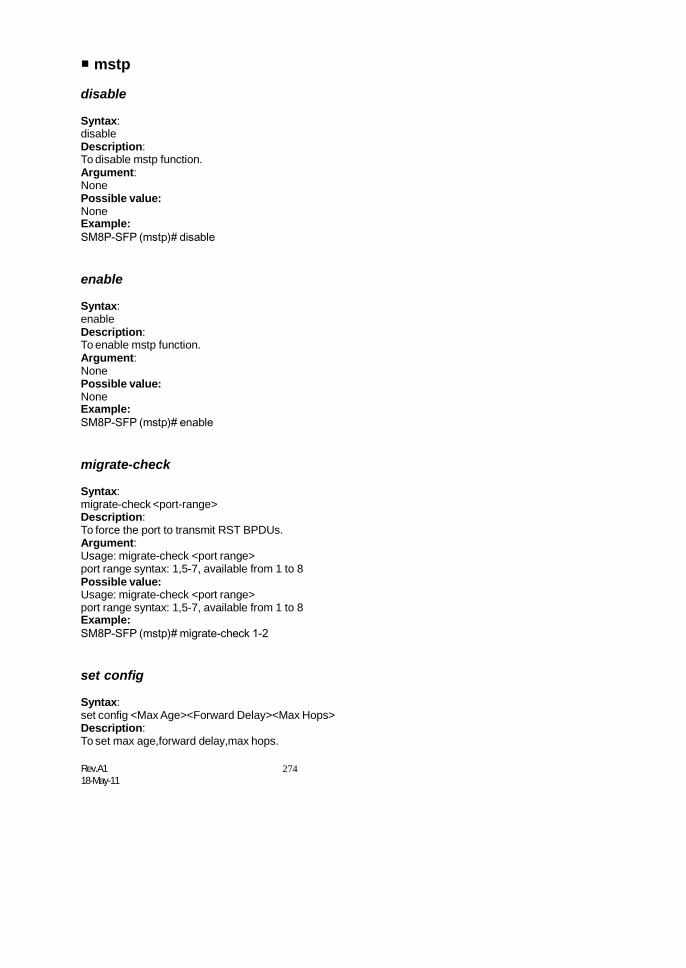
Rev.A118-May-11
274
mstp
disable
Syntax:disableDescription:To disable mstp function.Argument:NonePossible value:NoneExample:SM8P-SFP (mstp)# disable
enable
Syntax:enableDescription:To enable mstp function.Argument:NonePossible value:NoneExample:SM8P-SFP (mstp)# enable
migrate-check
Syntax:migrate-check <port-range>Description:To force the port to transmit RST BPDUs.Argument:Usage: migrate-check <port range>port range syntax: 1,5-7, available from 1 to 8Possible value:Usage: migrate-check <port range>port range syntax: 1,5-7, available from 1 to 8Example:SM8P-SFP (mstp)# migrate-check 1-2
set config
Syntax:set config <Max Age><Forward Delay><Max Hops>Description:To set max age,forward delay,max hops.

275 Rev.A118-May-11
Argument:<Max Age> : available from 6 to 40. Recommended value is 20<Forward Delay(sec)> : available from 4 to 30. Recommended value is 15<Max Hops> : available from 6 to 40. Recommended value is 20Possible value:<Max Age> : available from 6 to 40. Recommended value is 20<Forward Delay(sec)> : available from 4 to 30. Recommended value is 15<Max Hops> : available from 6 to 40. Recommended value is 20Example:SM8P-SFP(mstp)# set config 20 15 20 SM8P-SFP(mstp)#
set msti-vlan
Syntax:set msti-vlan <instance-id><vid-string>Description:To map Vlan ID(s) to an MSTIArgument:<instance-id> : MSTI id available from 1 to 4095<vid-string> : syntax example: 2.5-7.100-200Possible value:<instance-id> : available from 1 to 4094Example:SM8P-SFP(mstp)# set msti-vlan 2 2.5msti 2 had been successfully created and(or)vlan(s) have been added to map to this msti.SM8P-SFP(mstp)#
set p-cost
Syntax:set p-cost <instance_id> <port range> <path cost>Description:To set port path cost per instanceArgument:<port range> syntax: 1,5-7, available from 1 to 8<path cost> : 0, 1-200000000. The value zero means auto statusPossible value:<port range> : available from 1 to 8<path cost> : The value zero means auto status, 0-2000000000Example:SM8P-SFP(mstp)# set p-cost 2 6-8 0 SM8P-SFP(mstp)#
set p-edge
Syntax:

Rev.A118-May-11
276
set p-edge <port range> <admin edge>

277 Rev.A118-May-11
Description:To set per port admin edgeArgument:<port range> syntax: 1,5-7, available from 1 to 8<admin edge> : 0->non-edge port,1->edge portsPossible value:<port range> syntax: 1,5-7, available from 1 to 8<admin edge> : 0->non-edge port,1->edge portsExample:SM8P-SFP(mstp)# set p-edge 10-12 0 SM8P-SFP(mstp)#
set p-hello
Syntax:set p-hello <port range> <hello time>Description:To set per port hello timeArgument:<port range> : syntax: 1,5-7, available from 1 to 8<hello time> : only 1~2 are valid valuesPossible value:<port range> : syntax: 1,5-7, available from 1 to 8<hello time> : only 1~2 are valid valuesExample:SM8P-SFP(mstp)# set p-hello 5-10 1 SM8P-SFP(mstp)#
set p-p2p
Syntax:set p-p2p <port range> <admin p2p>Description:To set per port admin p2pArgument:<port range> syntax: 1,5-7, available from 1 to 8<admin p2p> : Admin point to point, <auto|true|false>Possible value:<port range> syntax: 1,5-7, available from 1 to 8<admin p2p> : Admin point to point, <auto|true|false>Example:SM8P-SFP(mstp)# set p-p2p 8-10 auto SM8P-SFP(mstp)#
set priority
Syntax:set priority <instance-id><Instance Priority>Description:To set instance priority

Rev.A118-May-11
278
Argument:<instance-id> : 0->CIST; 1-4095->MSTI<Instance Priority> : must be a multiple of 4096,available from 0 to 61440Possible value:<instance-id> : 0->CIST; 1-4095->MSTI<Instance Priority> : 0 to 61440Example:SM8P-SFP(mstp)# set priority 0 4096 SM8P-SFP(mstp)# enableMSTP startedSM8P-SFP(mstp)# show instance 0mstp status : enabledforce version : 3instance id: 0 bridgemax age : 20bridge forward delay : 15bridge max hops : 20 instancepriority : 4096bridge mac : 00:40:c7:5e:00:09CIST ROOT PRIORITY : 4096CIST ROOT MAC : 00:40:c7:5e:00:09CIST EXTERNAL ROOT PATHCOST : 0 CIST ROOT PORT ID : 0CIST REGIONAL ROOT PRIORITY : 4096CIST REGIONAL ROOT MAC : 00:40:c7:5e:00:09CIST INTERNAL ROOT PATH COST : 0CIST CURRENT MAX AGE : 20CIST CURRENT FORWARD DELAY : 15TIME SINCE LAST TOPOLOGY CHANGE(SECs) :2 TOPOLOGY CHANGE COUNT(SECs) : 0SM8P-SFP(mstp)#
set r-role
Syntax:set r-role <port range> <restricted role>Description:To set per port restricted roleArgument:<port range> syntax: 1,5-7, available from 1 to 8<restricted role> : 0->false,1->TruePossible value:<port range> : 1 to 8<restricted role> : 0->false,1->TrueExample:

279 Rev.A118-May-11
SM8P-SFP(mstp)# set r-role 1-4 1SM8P-SFP(mstp)# set r-role 5-6 0 SM8P-SFP(mstp)# show ports 0==== =========== ====== ========= ===== ===== ==Operational== =Restricted=Port Port Status Role Path Cost Pri Hello Edge-Port P2P Role Tcn

Rev.A118-May-11
280
Port Path Cost Priority Hello Edge-Port P2P Role Tcnsystem Enter in
==== =========== ====== ========= ===== ===== ========= ===== ====== =====1 FORWARDI
NGDSGN 200000 128 2/2 V
2 DISCARDING
dsbl 2000000 128 2/2 V3 DISCARDIN
Gdsbl 2000000 128 2/2 V
4 DISCARDING
dsbl 2000000 128 2/2 V5 FORWARDI
NGDSGN 200000 128 2/2 V V
6 DISCARDING
dsbl 2000000 128 2/2 V7 FORWARDI
NGDSGN 20000 128 2/2 V V
8 DISCARDING
dsbl 2000000 128 2/2 V V
SM8P-SFP(mstp)#
set r-tcn
Syntax:set r-tcn <port range> <restricted tcn>Description:To set per port restricted tcnArgument:<port range> syntax: 1,5-7, available from 1 to 8<restricted tcn> : 0->false,1->TruePossible value:<port range> : 1 to 8<restricted tcn> : 0->false,1->TrueExample:SM8P-SFP(mstp)# set r-tcn 1-5 1SM8P-SFP(mstp)# set r-tcn 6-8 1 SM8P-SFP(mstp)# show pconf 0
==== ========= ======== ===== ========= ===== ====== =====...(q to quit)2 0 128 2 true auto false false3 0 128 2 true auto false true4 0 128 2 true auto false true5 0 128 2 true auto false false6 0 128 2 true auto false false7 0 128 2 true auto false false8 0 128 2 true auto true false9 0 128 2 true auto true true
SM8P-SFP(mstp)#
set region-name
Syntax:set region-name <string>Description:To set mstp region name(0~32 bytes)

281 Rev.A118-May-11
Argument:<string> :a null region name

Rev.A118-May-11
282
Possible value:<string> :1-32Example:SM8P-SFP(mstp)# set region-name test2 SM8P-SFP(mstp)# show region-info
Name : test2Revision : 0Instances : 0SM8P-SFP(mstp)#
set revision-level
Syntax:set rev <revision-level>Description:To set mstp revision-level(0~65535)Argument:<revision-level> :0~65535Possible value:<revision-level> :0~65535Example:SM8P-SFP(mstp)# set revision-level 30000 SM8P-SFP(mstp)# show region-info
Name : test2Revision : 30000Instances : 0SM8P-SFP(mstp)#
set version
Syntax:set version <stp|rstp|mstp>Description:To set force-versionArgument:<revision-level> :0~65535Possible value:<revision-level> :0~65535Example:GS-2924(mstp)# set version mstp
show instance
Syntax:show instance <instance-id>Description:To show instance status

283 Rev.A118-May-11
Argument:

Rev.A118-May-11
284
<instance-id>:0->CIST;1-4095->MSTIPossible value:<instance-id>:0->CIST;1-4095->MSTIExample:SM8P-SFP(mstp)# show instance 0mstp status : enabledforce version : 2 instanceid: 0bridge max age : 20 bridgeforward delay : 15bridge max hops : 20instance priority : 4096bridge mac : 00:40:c7:5e:00:09CIST ROOT PRIORITY : 4096CIST ROOT MAC : 00:40:c7:5e:00:09CIST EXTERNAL ROOT PATHCOST : 0CIST ROOT PORT ID : 0CIST REGIONAL ROOT PRIORITY : 4096CIST REGIONAL ROOT MAC : 00:40:c7:5e:00:09CIST INTERNAL ROOT PATH COST : 0CIST CURRENT MAX AGE : 20CIST CURRENT FORWARD DELAY : 15TIME SINCE LAST TOPOLOGY CHANGE(SECs) :2569 TOPOLOGY CHANGE COUNT(SECs) : 0SM8P-SFP(mstp)#
show pconf
Syntax:show pconf <instance-id>Description:To show port configurationArgument:instance-id:0->CIST;1-4095->MSTIPossible value:<instance-id>:0->CIST;1-4095->MSTIExample:SM8P-SFP(mstp)# show pconf 0
set r-role Se2 0 128 2 true auto false false3 0 128 2 true auto false true4 0 128 2 true auto false true5 0 128 2 true auto false false6 0 128 2 true auto false false7 0 128 2 true auto false false8 0 128 2 true auto true false

285 Rev.A118-May-11
SM8P-SFP(mstp)#

Rev.A118-May-11
280
show ports
Syntax:show ports <instance-id>Description:To show port statusArgument:instance-id:0->CIST;1-4095->MSTIPossible value:<instance-id>:0->CIST;1-4095->MSTIExample:SM8P-SFP(mstp)# show ports 0
show region-info
Syntax:show region-infoDescription:To show region configArgument:nonePossible value:noneExample:SM8P-SFP(mstp)# show region-info
Name : test2Revision : 30000Instances : 0SM8P-SFP(mstp)#
show vlan-map
Syntax:show vlan-map <instance-id>Description:To show vlan mapping of an instanceArgument:<nstance-id>:0->CIST;1-4095->MSTIPossible value:<instance-id>:0->CIST;1-4095->MSTIExample:SM8P-SFP(mstp)# show vlan-map 0instance 0 has those vlans :0-4095SM8P-SFP(mstp)#

281 Rev.A118-May-11
policy
add
Syntax:add [name <value>] [ip <value>] [port <value>] [type <value>] action <value>Description:To add a new management policy entry.Argument:Synopsis: add name George ip 192.168.1.77-192.168.1.90 port 2-5,8
type h,s action aSynopsis: add name Mary ip 192.168.2.1-192.168.2.90 action denyPossible value:NoneExample:SM8P-SFP(policy)# add name Mary ip 192.168.3.1-192.168.3.4 action denySM8P-SFP(policy)#show1) Name : george IP Range : 192.168.1.1-192.168.1.90
Action : Accept Access Type : HTTPSNMP Port : 2 3 4 5 8
2) Name : rule1 IP Range : 192.168.2.1-192.168.2.30Action : Deny Access Type : HTTP TELENTSNMP Port : 11 12 13 14 15
3) Name : Mary IP Range : 192.168.3.1-192.168.3.4Action : Deny Access Type : AnyPort : Any
SM8P-SFP(policy)#
delete
Syntax:delete <index>Description:To add a new management policy entry.Argument:<index> : a specific or range management policy entry(s)e.g. delete 2,3,8-12Possible value:<index> : a specific or range management policy entry(s)Example:SM8P-SFP(policy)# add name rule2 ip 192.168.4.23-192.168.4.33 port 6-8 types,taction dSM8P-SFP(policy)#show

Rev.A118-May-11
282
1) Name : rule1 IP Range : 192.168.4.5-192.168.4.22Action : Deny Access Type : HTTP TELENT SNMP

283 Rev.A118-May-11
Port : 2 3 4 5
2) Name : rule2 IP Range : 192.168.4.23-192.168.4.33Action : Deny Access Type : TELENT SNMPPort : 6 7 8
SM8P-SFP(policy)# delete 2 SM8P-SFP(policy)#show1) Name : rule1 IP Range : 192.168.4.5-192.168.4.22
Action : Deny Access Type : HTTP TELENTSNMP Port : 2 3 4 5
SM8P-SFP(policy)#
show
Syntax:showDescription:To show management policy list.Argument:nonePossible value:noneExample:SM8P-SFP(policy)#show1) Name : rule1 IP Range : 192.168.4.5-192.168.4.22
Action : Deny Access Type : HTTP TELENTSNMP Port : 2 3 4 5
2) Name : rule2 IP Range : 192.168.4.23-192.168.4.33Action : Deny Access Type : TELENTSNMP Port : 6 7 8

Rev.A118-May-11
284
port
clear counter
Syntax:clear counterDescription:To clear all ports’ counter (include simple and detail port counter) information.Argument:NonePossible value:NoneExample:SM8P-SFP (port)# clear counter
set description
Syntax:set description <port-range> <description>Description:To set port descriptionArgument:<port range> syntax : 1,5-7, available from 1 to 8<description> : set port description, max 47 charactersPossible value:<port range> : 1 to 8<description> : max 47 charactersExample:SM8P-SFP(port)# set description 3-8 salesdepartment SM8P-SFP(port)# show config
Speed/ Flow Maximum ExcessiveSynopsis: add name George ip192.168.1.77-Port Duplex Control Frame Collision Description
type2 Auto Disabled 9600 Discard3 Auto Disabled 9600 Discard salesdepartment4 Auto Disabled 9600 Discard salesdepartment5 Auto Disabled 9600 Discard salesdepartment6 Auto Disabled 9600 Discard salesdepartment7 Auto Disabled 9600 Discard salesdepartment8 Auto Disabled 9600 Discard salesdepartment
set excessive-collision
Syntax:set excessive-collision <port-range> <discard|restart>Description:To set port description
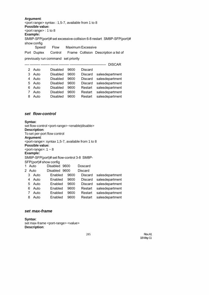
285 Rev.A118-May-11
1 Auto Disabled 9600 Doscard2 Auto Disabled 9600 Discard
3 Auto Enabled 9600 Discard salesdepartment4 Auto Enabled 9600 Discard salesdepartment5 Auto Enabled 9600 Discard salesdepartment6 Auto Enabled 9600 Restart salesdepartment7 Auto Enabled 9600 Restart salesdepartment8 Auto Enabled 9600 Restart salesdepartment
Argument:<port range> syntax : 1,5-7, available from 1 to 8Possible value:<port range> : 1 to 8Example:SM8P-SFP(port)# set excessive-collision 6-8 restart SM8P-SFP(port)#show config
Speed/ Flow Maximum ExcessivePort Duplex Control Frame Collision Description a list ofpreviously run command set priority---- --------- -------- ------- --------- -------------------------------- DISCAR
2 Auto Disabled 9600 Discard3 Auto Disabled 9600 Discard salesdepartment4 Auto Disabled 9600 Discard salesdepartment5 Auto Disabled 9600 Discard salesdepartment6 Auto Disabled 9600 Restart salesdepartment7 Auto Disabled 9600 Restart salesdepartment8 Auto Disabled 9600 Restart salesdepartment
set flow-control
Syntax:set flow-control <port-range> <enable|disable>Description:To set per-port flow controlArgument:<port-range>: syntax 1,5-7, available from 1 to 8Possible value:<port-range>: 1 ~ 8Example:SM8P-SFP(port)# set flow-control 3-8 SM8P-SFP(port)# show config
set max-frame
Syntax:set max-frame <port-range> <value>Description:

Rev.A118-May-11
286
To set per-port maximum frame sizeArgument:<port range> syntax : 1,5-7, available from 1 to 8<value> : Allowed value are 1518-9600 bytes.Possible value:<port range> syntax : 1 to 8<value> : 1518-9600 bytes.Example:SM8P-SFP(port)# set max-frame 3-6 1518 SM8P-SFP(port)# show config
Speed/ Flow Maximum Excessiveommands2 Auto Disabled 9600 Discard3 Auto Enabled 1518 Discard salesdepartment4 Auto Enabled 1518 Discard salesdepartment5 Auto Enabled 1518 Discard salesdepartment6 Auto Enabled 1518 Restart salesdepartment7 Auto Enabled 9600 Restart salesdepartment8 Auto Enabled 9600 Restart salesdepartment
set speed
Syntax:set speed <port-range> <disable|auto|1Gfull|100full|100half|10full|10halfDescription:To set port capability.Argument:<port-range>:syntax 1,5-7, available from 1 to 8<port-speed>:auto: set auto-negotiation mode10half: set speed/duplex 10M Half10full: set speed/duplex 10M Full100half: set speed/duplex 100M Half100full: set speed/duplex 100M Full1Gfull: set speed/duplex 1G FullPossible value:<port-range>: 1 to 8<port-speed>: auto, 10half, 10full, 100half, 100full, 1GfullExample:SM8P-SFP(port)# set speed 3 auto SM8P-SFP(port)# show status
Speed/Port Link Duplex Rx Pause Tx Pause Description---- ---- --------- -------- -------- --------------------------------
1 Up 100M/Full Disabled Disabled2 Down Down Disabled Disabled3 Up 100M/Full Disabled Disabled4 Down Down Disabled Disabled5 Down Down Disabled Disabled
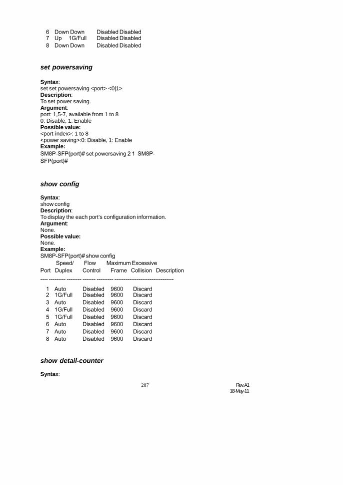
287 Rev.A118-May-11
6 Down Down Disabled Disabled7 Up 1G/Full Disabled Disabled8 Down Down Disabled Disabled
set powersaving
Syntax:set set powersaving <port> <0|1>Description:To set power saving.Argument:port: 1,5-7, available from 1 to 80: Disable, 1: EnablePossible value:<port-index>: 1 to 8<power saving>:0: Disable, 1: EnableExample:SM8P-SFP(port)# set powersaving 2 1 SM8P-SFP(port)#
show config
Syntax:show configDescription:To display the each port’s configuration information.Argument:None.Possible value:None.Example:SM8P-SFP(port)# show config
Speed/ Flow Maximum ExcessivePort Duplex Control Frame Collision Description---- --------- -------- ------- --------- --------------------------------
1 Auto Disabled 9600 Discard2 1G/Full Disabled 9600 Discard3 Auto Disabled 9600 Discard4 1G/Full Disabled 9600 Discard5 1G/Full Disabled 9600 Discard6 Auto Disabled 9600 Discard7 Auto Disabled 9600 Discard8 Auto Disabled 9600 Discard
show detail-counter
Syntax:

Rev.A118-May-11
288
show detail-counter <port>

289 Rev.A118-May-11
Description:To display the display detail port counter.Argument:<port>: port, available from 1 to 8Possible value:<port>:1 ~ 8Example:SM8P-SFP (port)# show detail-counter 3
Rx Multicast 6 Tx Multicast 641Rx Broadcast 94 Tx Broadcast 5251Rx Pause 0 Tx Pause 0
Receive Size Counters Transmit Size Counters------------------------------- ------------------------------------Rx 64 Bytes 7381 Tx 64 Bytes 4351Rx 65-127 Bytes 291 Tx 65-127 Bytes 2342Rx 128-255 Bytes 118 Tx 128-255 Bytes 605Rx 256-511 Bytes 53 Tx 256-511 Bytes 1081Rx 512-1023 Bytes 33 Tx 512-1023 Bytes 144Rx 1024-1526 Bytes 28 Tx 1024-1526 Bytes 11453Rx 1527- Bytes 0 Tx 1527- Bytes 0
Receive Error Counters Transmit Error Counters---------------------------- ------------------------------------
Rx Drops 0 Tx Drops 0Rx CRC/Alignment 0 Tx Late/Exc. Coll. 0Rx Undersize 0Rx Oversize 0Rx Fragments 0Rx Jabber 0
show sfp
Syntax:show sfp <port>Description:To display the SFP module information.Argument:<port>: SFP port of the switch, available from 1, 8Possible value:<port>: 1- 8,Example:SM8P-SFP(port)# show sfp 11 Port11 SFP information---------------------------------------------------------------------Connector Type : SFP - Unknown or unspecifiedFiber Type : Reserved

Rev.A118-May-11
290
Tx Central Wavelength : 0

291 Rev.A118-May-11
Baud Rate : 1GVendor OUI : 00:00:00Vendor Name : FIBERXON INC.Vendor PN : FTM-C012R-LCVendor Rev : 10Vendor SN : PP220052901281Date Code : 051012Temperature : noneVcc : noneMon1 (Bias) mA : noneMon2 (TX PWR) : noneMon3 (RX PWR) : noneSM8P-SFP(port)#
Port 23 SFP information---------------------------------------------------------------------Connector Type : SFP - LCFiber Type : Multi-mode (MM)Tx Central Wavelength : 850Baud Rate : 1GVendor OUI : 00:40:c7Vendor Name : APAC OptoVendor PN : KM28-C3S-TC-NVendor Rev : 0000Vendor SN : 5425010708Date Code : 050530Temperature : noneVcc : noneMon1 (Bias) mA : noneMon2 (TX PWR) : noneMon3 (RX PWR) : none
show simple-counter
Syntax:showsimple-counterDescription:To display the summary counting of each port’s traffic.Argument:None.Possible value:None.Example:SM8P-SFP (port)# show simple-counterset max-frame Set per-port maximum frame size
3 0 0 0 0 0 0 0 0

Rev.A118-May-11
292
4 0 0 0 0 0 0 0 0

293 Rev.A118-May-11
5 0 0 0 0 0 0 0 06 0 0 0 0 0 0 0 07 0 0 0 0 0 0 0 08 0 0 0 0 0 0 0 0
SM8P-SFP(port)#
show status
Syntax:show statusDescription:To display the port’s current status.Argument:None.Possible value:None.Example:SM8P-SFP(port)# show status
Speed/1G/Full DisablePort Link Duplex Rx Pause Tx Pause Description
3 Auto Disabled 9600 Discard2 Down Down Disabled Disabled3 Up 100M/Full Disabled Disabled4 Down Down Disabled Disabled5 Down Down Disabled Disabled6 Down Down Disabled Disabled7 Up 1G/Full Disabled Disabled8 Down Down Disabled Disabled
SM8P-SFP(port)#
show powersaving
Syntax:show powersavingDescription:To display powersaving port information.Argument:NonePossible value:NoneExample:SM8P-SFP(port)# show powersaving PortPower Saving---- ------------

Rev.A118-May-11
294
1 Disabled2 Enabled


Rev.A118-May-11
290
3 Disabled4 Disabled5 Disabled6 Disabled7 Disabled8 Disabled
SM8P-SFP(port)#
qos
<<ports>>
set class
Syntax:set class <#>Description:To set number of classes.Argument:#: Number of classes, available 1, 2, 4Possible value:<#>: 1,2,4Example:SM8P-SFP(qos-ports)# set class 2 SM8P-SFP(qos-ports)#
set port
Syntax:set port <range> <default class> <qcl> <user priority> <queuing mode> <low queue weighted> <normal queue weighted> <medium queue weighted> <highqueue weighted>Description:To set port information.Argument:<range syntax>: 1,5-7, available from 1 to 8<default class option>: low | normal | medium | high<qcl> : available from 1 to 8<user priority>: available from 0 to 7<queuing mode>: strict | weighted<low queue weighted>: 1 / 2 / 4 / 8<normal queue weighted>: 1 / 2 / 4 / 8<medium queue weighted> : 1 / 2 / 4 / 8<high queue weighted>: 1 / 2 / 4 / 8Possible value:

Argument: 291 Rev.A1
18-May-11
<range syntax>: 1 to 8

Rev.A118-May-11
292
2 Medium 1 3 Weighted Fair 2 / 2 / 2 / 23 Low 1 0 Strict Priority 1 / 2 / 4 / 84 Low 1 0 Strict Priority 1 / 2 / 4 / 85 Low 1 0 Strict Priority 1 / 2 / 4 / 86 Low 1 0 Strict Priority 1 / 2 / 4 / 87 Low 1 0 Strict Priority 1 / 2 / 4 / 88 Low 1 0 Strict Priority 1 / 2 / 4 / 8
<default class option>: low | normal | medium | high<qcl> : 1 to 8<user priority>: 0 to 7<queuing mode>: strict | weighted<low queue weighted>: 1 / 2 / 4 / 8<normal queue weighted>: 1 / 2 / 4 / 8<medium queue weighted> : 1 / 2 / 4 / 8<high queue weighted>: 1 / 2 / 4 / 8Example:SM8P-SFP(qos-ports)# set port 2 medium 1 3 weithted 2 2 2 2 SM8P-SFP(qos-ports)#show
2 Medium 1 3 Weighted Fair 2 / 2 / 2 / 23 Low 1 0 Strict Priority 1 / 2 / 4 / 84 Low 1 0 Strict Priority 1 / 2 / 4 / 85 Low 1 0 Strict Priority 1 / 2 / 4 / 86 Low 1 0 Strict Priority 1 / 2 / 4 / 87 Low 1 0 Strict Priority 1 / 2 / 4 / 88 Low 1 0 Strict Priority 1 / 2 / 4 / 8
SM8P-SFP(qos-ports)#
show
Syntax:showDescription:To show port information.Argument:nonePossible value:noneExample:SM8P-SFP(qos-ports)#showNumber of Classes:2
<<qcl>>
set
Syntax:

Argument: 293 Rev.A1
18-May-11
set <dscp> < tos> < tagpriority> <qce type> <value> <class>Description:To add the QCE entry in the specific QCL

Rev.A118-May-11
294
<dscp>: dscp field, syntax 1,5-7, available from 0 to 63< tos> : tos priority , available from 1 to 8< tagpriority> : tag priority, available from 1 to 8<qce type> : ethernet<value> : 0xfff0<class> : highPossible value:<dscp>: dscp field, syntax 1,5-7, available from 0 to 63< tos> : tos priority , available from 1 to 8< tagpriority> : tag priority, available from 1 to 8<qce type> : ethernet<value> : 0xfff0<class> : highExample:SM8P-SFP(qos-qcl)# set 2 0 3 ethernet 0xfff0 highSM8P-SFP(qos-qcl)# show 2 1
QCE Type: Ethernet TypeEthernet Type Value:0xfff0 TrafficClass: High
SM8P-SFP(qos-qcl)#
move
Syntax:move <qcl> <qce> <new qce>Description:To move up the specific QCE entry in the specific QCLArgument:<qcl> : the qcl number, available from 1 to 8.<qce> : the original qce number, available from 1 to 12.<new qce> : the new qce number, available from 1 to 12.Possible value:<qcl> : available from 1 to 8.<qce> : available from 1 to 12.<new qce> : available from 1 to 12.Example:SM8P-SFP(qos-qcl)# move 2 1 1
delete
Syntax:delete <qcl> <qce range>Description:To delete the specific QCE entry in the specific QCL.Argument:<qcl> : the qcl number, available from 1 to 8.<qce range> : 1,5-7, available from 1 to 12

Argument: 295 Rev.A1
18-May-11
Possible value:<qcl> : available from 1 to 8.

Rev.A118-May-11
296
<qce range> : available from 1 to 12Example:SM8P-SFP(qos-qcl)# delete 2 1
<<rate>>
set
Syntax:set <range> <policer enabled> <rate> <unit> <shaper enabled> <rate> <unit>Description:To set rate limit configurationArgument:<range syntax> : 1,5-7, available from 1 to 8<policer enabled> : 1 means enable and 0 means disable
<rate>: allowed values are 500kbps-1Gkps<unit>: 'k' means kbps and 'm' means mbps
<shaper enabled>: 1 means enable and 0 means disable<rate>: allowed values are 500kbps-1Gkps<unit>: 'k' means kbps and 'm' means mbps
Possible value:range syntax: 1,5-7, available from 1 to 8policer enabled: 1 means enable and 0 means disable
rate: allowed values are 500kbps-1Gkpsunit: 'k' means kbps and 'm' means mbps
shaper enabled: 1 means enable and 0 means disablerate: allowed values are 500kbps-1Gkpsunit: 'k' means kbps and 'm' means mbps
Example:SM8P-SFP(qos-rate)# set 2 1 1000 m 1 1000 mSM8P-SFP(qos-rate)#show
2 V 1000 Mbps V 1000 Mbps3 500 kbps 500 kbps
4 500 kbps 500 kbps5 500 kbps 500 kbps6 500 kbps 500 kbps7 500 kbps 500 kbps8 500 kbps 500 kbps
<< storm >>
set broadcast
Syntax:set broadcast <status> <rate>Description:To set broadcast storm control configuration

Argument: 297 Rev.A1
18-May-11
<status> : 1 means enable and 0 means disable<rate> : 1, 2, 4, 8, 16, 32, 64, 128, 256, 512, 1k, 2k, 4k, 8k, 16k, 32k, 64k, 128k, 256k, 512kPossible value:<status> : 1 means enable and 0 means disable<rate> : 1, 2, 4, 8, 16, 32, 64, 128, 256, 512, 1k, 2k, 4k, 8k, 16k, 32k, 64k, 128k, 256k, 512kExample:SM8P-SFP(qos-storm)# set broadcast 1 512SM8P-SFP(qos-storm)#show
Frame Type Status Rate(Packet Per Second)------------------------------------------------Flooded unicast 1Multicast 1Broadcast V 512
set multicast
Syntax:set multicast <status> <rate>Description:To set multicast storm control configurationArgument:<status> : 1 means enable and 0 means disable<rate> : 1, 2, 4, 8, 16, 32, 64, 128, 256, 512, 1k, 2k, 4k, 8k, 16k, 32k, 64k, 128k, 256k, 512kPossible value:<status> : 1 means enable and 0 means disable<rate> : 1, 2, 4, 8, 16, 32, 64, 128, 256, 512, 1k, 2k, 4k, 8k, 16k, 32k, 64k, 128k, 256k, 512kExample:SM8P-SFP(qos-storm)# set multicast 1 64 SM8P-SFP(qos-storm)#show
Frame Type Status Rate(Packet Per Second)------------------------------------------------Flooded unicast 1Multicast V 64Broadcast V 512
set unicast
Syntax:set unicast <status> <rate>Description:To set flooded unicast storm control configuration

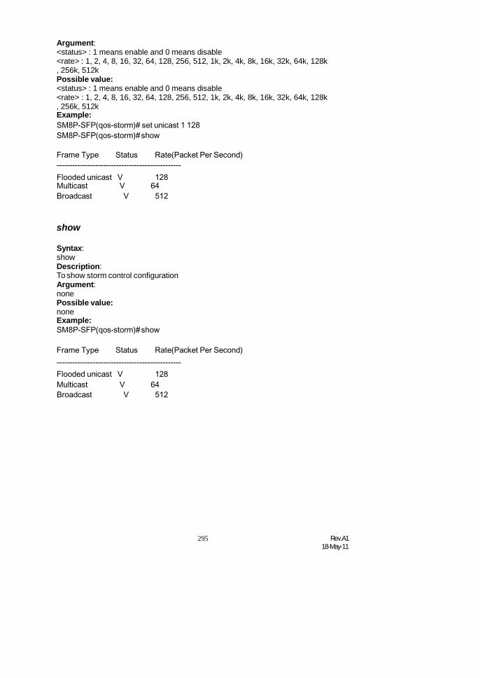
295 Rev.A118-May-11
Argument:<status> : 1 means enable and 0 means disable<rate> : 1, 2, 4, 8, 16, 32, 64, 128, 256, 512, 1k, 2k, 4k, 8k, 16k, 32k, 64k, 128k, 256k, 512kPossible value:<status> : 1 means enable and 0 means disable<rate> : 1, 2, 4, 8, 16, 32, 64, 128, 256, 512, 1k, 2k, 4k, 8k, 16k, 32k, 64k, 128k, 256k, 512kExample:SM8P-SFP(qos-storm)# set unicast 1 128SM8P-SFP(qos-storm)#show
Frame Type Status Rate(Packet Per Second)------------------------------------------------Flooded unicast V 128Multicast V 64Broadcast V 512
show
Syntax:showDescription:To show storm control configurationArgument:nonePossible value:noneExample:SM8P-SFP(qos-storm)#show
Frame Type Status Rate(Packet Per Second)------------------------------------------------Flooded unicast V 128Multicast V 64Broadcast V 512

Rev.A118-May-11
296
reboot
reboot
Syntax:rebootDescription:To reboot the system.Argument:None.Possible value:None.Example:SM8P-SFP# reboot
snmp
<<disable>>
Syntax:disable set-abilitydisable snmpDescription:The Disable here is used for the de-activation of snmp or set-community.Argument:None.Possible value:None.Example:SM8P-SFP(snmp)# disable snmpSM8P-SFP(snmp)# disable set-ability
<<enable>>
Syntax:enable set-abilityenable snmpDescription:The Enable here is used for the activation snmp or set-community.Argument:None.Possible value:None.Example:SM8P-SFP(snmp)# enable snmpSM8P-SFP(snmp)# enable set-ability
<<set>>

297 Rev.A118-May-11
Syntax:set get-community <community>set set-community <community>set trap <#> <ip> [port] [community]Description:The Set here is used for the setup of get-community, set-community, trap host ip,host port and trap-community.Argument:<#>: trap number<ip>: ip address or domain name<port>: trap port<community>:trap community namePossible value:<#>: 1 to 6<port>:1~65535Example:SM8P-SFP(snmp)# set get-community publicSM8P-SFP(snmp)# set set-community privateSM8P-SFP(snmp)# set trap 1 192.168.1.77 162 public
show
Syntax:showDescription:The Show here is to display the configuration of SNMP.Argument:None.Possible value:None.Example:SM8P-SFP(snmp)#show SNMP : EnableGet Community: publicSet Community: private [Enable]Trap Host 1 IP Address: 192.168.1.77 Port: 162 Community: public TrapHost 2 IP Address: 0.0.0.0 Port: 162 Community: publicTrap Host 3 IP Address: 0.0.0.0 Port: 162 Community: public TrapHost 4 IP Address: 0.0.0.0 Port: 162 Community: public Trap Host5 IP Address: 0.0.0.0 Port: 162 Community: public Trap Host 6 IPAddress: 0.0.0.0 Port: 162 Community: public

Rev.A118-May-11
298
stp
MCheck
Syntax:MCheck <range>Description:To force the port to transmit RST BPDUs.Argument:<range>: syntax 1,5-7, available from 1 to 8Possible value:<range>: 1 to 8Example:SM8P-SFP(stp)# Mcheck 1-8
disable
Syntax:disableDescription:To disable the STP function.Argument:None.Possible value:None.Example:SM8P-SFP(stp)# disable
enable
Syntax:enableDescription:To enable the STP function.Argument:None.Possible value:None.Example:SM8P-SFP(stp)# enable
set config
Syntax:set config <Bridge Priority> <Hello Time> <Max. Age> <Forward Delay>Description:To set up the parameters of STP.Argument:<Bridge Priority>:priority must be a multiple of 4096, available from 0 to 61440.<Hello Time>: available from 1 to 10.
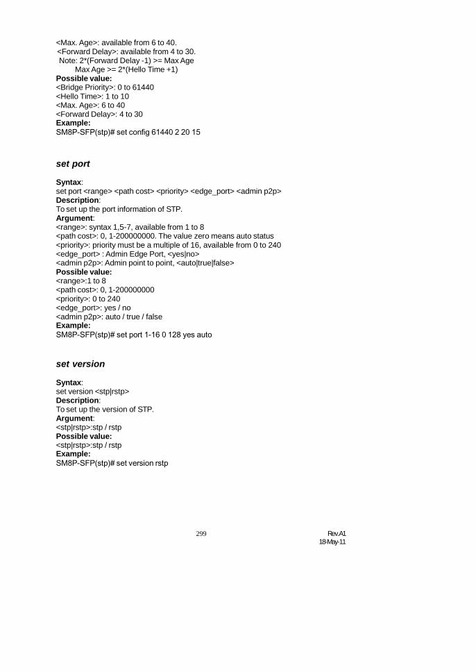
299 Rev.A118-May-11
<Max. Age>: available from 6 to 40.<Forward Delay>: available from 4 to 30.Note: 2*(Forward Delay -1) >= Max Age
Max Age >= 2*(Hello Time +1)Possible value:<Bridge Priority>: 0 to 61440<Hello Time>: 1 to 10<Max. Age>: 6 to 40<Forward Delay>: 4 to 30Example:SM8P-SFP(stp)# set config 61440 2 20 15
set port
Syntax:set port <range> <path cost> <priority> <edge_port> <admin p2p>Description:To set up the port information of STP.Argument:<range>: syntax 1,5-7, available from 1 to 8<path cost>: 0, 1-200000000. The value zero means auto status<priority>: priority must be a multiple of 16, available from 0 to 240<edge_port> : Admin Edge Port, <yes|no><admin p2p>: Admin point to point, <auto|true|false>Possible value:<range>:1 to 8<path cost>: 0, 1-200000000<priority>: 0 to 240<edge_port>: yes / no<admin p2p>: auto / true / falseExample:SM8P-SFP(stp)# set port 1-16 0 128 yes auto
set version
Syntax:set version <stp|rstp>Description:To set up the version of STP.Argument:<stp|rstp>:stp / rstpPossible value:<stp|rstp>:stp / rstpExample:SM8P-SFP(stp)# set version rstp

Rev.A118-May-11
300
1 DISCARDING
2000000 128 No Auto2 DISCARDIN
G2000000 128 No Auto
3 DISCARDING
2000000 128 No Auto
show config
Syntax:show configDescription:To display the configuration of STP.Argument:None.Possible value:None.Example:SM8P-SFP(stp)# show configSTP State Configuration :Spanning Tree Protocol : EnabledBridge Priority (0-61440) : 61440Hello Time (1-10 sec) : 2Max. Age (6-40 sec) : 20Forward Delay (4-30 sec) : 15Force Version :RSTP
show port
Syntax:show portDescription:To display the port information of STP.Argument:None.Possible value:None.Example:SM8P-SFP# stpSM8P-SFP(stp)# show portPort Port Status Path Cost Priority Admin Edge Port Admin Point To Point==== =========== ========= ======== =============== ====================
……
show status
Syntax:show statusDescription:To display the status of STP.Argument:

301 Rev.A118-May-11
None.Possible value:None.

Rev.A118-May-11
302
Example:SM8P-SFP(stp)# show statusSTP Status :STP State : EnabledBridge ID : 00:40:C7:D8:09:1DBridge Priority : 61440Designated Root : 00:40:C7:D8:09:1DDesignated Priority : 61440Root Port : 0Root Path Cost : 0Current Max. Age(sec) : 20Current Forward Delay(sec) : 15Hello Time(sec) : 2STP Topology Change Count : 0Time Since Last Topology Change(sec) : 848
syslog
disable
Syntax:DiableDescription:To disable syslog function.Argument:<None>Possible value:<None>Example:SM8P-SFP(syslog)#diable SM8P-SFP(syslog)#
enable
Syntax:enableDescription:To enable syslog function.Argument:<None>Possible value:<None>Example:SM8P-SFP(syslog)#enable SM8P-SFP(syslog)#

303 Rev.A118-May-11
Set server
Syntax:set server <ip> <port>Description:To Set syslog Host IP and Port.Argument:<ip > : syslog server ip<port> : trap portPossible value:<ip > : syslog server ip<port> : trap portExample:SM8P-SFP(syslog)# set server 192.168.22.0 8SM8P-SFP(syslog)#SM8P-SFP(syslog)#showsyslog : EnableSyslog Host IP: 192.168.22.0 Port: 8
system
set contact
Syntax:set contact <contact string>Description:To set the contact description of the switch.Argument:<contact>:string length up to 40 characters.Possible value:<contact>: A, b, c, d, ... ,z and 1, 2, 3, …. etc.Example:SM8P-SFP(system)# set contact Taipei
set device-name
Syntax:set device-name <device-name string>Description:To set the device name description of the switch.Argument:<device-name>: string length up to 40 characters.Possible value:<device-name>: A, b, c, d, ... ,z and 1, 2, 3, …. etc.Example:SM8P-SFP(system)# set device-name CR-2600

Rev.A118-May-11
304
set location
Syntax:set location <location string>Description:To set the location description of the switch.Argument:<location>: string length up to 40 characters.Possible value:<location>: A, b, c, d, ... ,z and 1, 2, 3, …. etc.Example:SM8P-SFP(system)# set location Taipei
show
Syntax:showDescription:To display the basic information of the switch.Argument:None.Possible value:None.Example:SM8P-SFP(system)#showModel Name : SM8P-SFPSystem Description : L2 Managed SwitchLocation :Contact :Device Name : SM8P-SFPSystem Up Time : 0 Days 0 Hours 4 Mins 14 SecsCurrent Time : Tue Jan 17 16:28:46 2006BIOS Version : v1.05Firmware Version : v1.53Hardware-Mechanical Version : v1.01-v1.01Serial Number :030C02000003Host IP Address : 192.168.1.77Host MAC Address : 00-40-c7-e7-00-10Device Port : TP * 6, Dual-Media Port(RJ45/SFP) * 2RAM Size : 16 MFlash Size : 2 M

305 Rev.A118-May-11
traplog
clear
Syntax:clearDescription:To clear trap log.Argument:nonePossible value:noneExample:SM8P-SFP(traplog)#clear SM8P-SFP(traplog)#show
No time desc
------------------------------- ------------------------------------
show
Syntax:showDescription:To display the trap log.Argument:None.Possible value:None.Example:SM8P-SFP(tftp)# show2 Mon Mar 17 15:18:38 2008gvrp mode> <qce type> .
Dual Media Swapped [Port:1][SwapTo:TP]ge hostnamexit / 4 / 83 Mon Mar 17 15:18:38 2008nto igmp mode, available from
Link Up [Port:1]Enter into ip mode6 Mon Mar 17 15:18:38 2008
Dual Media Swapped [Port:5][SwapTo:TP]7 Mon Mar 17 15:18:38 2008
8 Mon Mar 17 15:18:48 2008Link Up [Port:5]
Login [admin]

Rev.A118-May-11
306
time
set daylightsaving
Syntax:set daylightsaving <hr> <MM/DD/HH> <mm/dd/hh>Description:To set up the daylight saving.Argument:hr : daylight saving hour, range: -5 to +5 MM
: daylight saving start Month (01-12)DD : daylight saving start Day (01-31)HH : daylight saving start Hour (00-23) mm
: daylight saving end Month (01-12) dd: daylight saving end Day (01-31)
hh : daylight saving end Hour (00-23)Possible value:hr : -5 to +5MM : (01-12)DD : (01-31)HH : (00-23)mm : (01-12)dd : (01-31)hh : (00-23)Example:SM8P-SFP(time)# set daylightsaving 3 10/12/01 11/12/01 SaveSuccessfully
set manual
Syntax:set manual <YYYY/MM/DD> <hh:mm:ss>Description:To set up the current time manually.Argument:YYYY : Year (2000-2036) MM : Month (01-12)DD : Day (01-31) hh : Hour (00-23)mm : Minute (00-59) ss : Second (00-59)Possible value:YYYY : (2000-2036) MM : (01-12)DD : (01-31) hh : (00-23)mm : (00-59) ss : (00-59)Example:SM8P-SFP(time)# set manual 2004/12/23 16:18:00

307 Rev.A118-May-11
set ntp
Syntax:set ntp <ip> <timezone>Description:To set up the current time via NTP server.Argument:<ip>: ntp server ip address or domain name<timezone>: time zone (GMT), range: -12 to +13Possible value:<timezone>: -12,-11…,0,1…,13Example:SM8P-SFP(time)# set ntp clock.via.net 8Synchronizing...(1)Synchronizationsuccess
show
Syntax:showDescription:To show the time configuration, including “Current Time”, “NTP Server”,” Timezone”,” Daylight Saving”,” Daylight Saving Start” and “Daylight Saving End”Argument:None.Possible value:None.Example:SM8P-SFP(time)# showCurrent Time : Thu Thu 14 15:04:03 2005NTP Server : 209.81.9.7Timezone : GMT+8:00Day light Saving : 0 HoursDay light Saving Start : Mth: 1 Day: 1 Hour: 0Day light Saving End : Mth: 1 Day: 1 Hour: 0SM8P-SFP(time)#
trunk
del trunk
Syntax:del trunk <port-range>Description:To delete the trunking port.Argument:<port-range>: port range, syntax 1,5-7, available from 1 to 8Possible value:

Rev.A118-May-11
308
<port-range>: 1 to 8Example:SM8P-SFP(trunk)# del trunk 1
set priority
Syntax:set priority <range>Description:To set up the LACP system priority.Argument:<range>: available from 1 to 65535.Possible value:<range>: 1 to 65535, default: 32768Example:SM8P-SFP(trunk)# set priority 33333
set trunk
Syntax:set trunk <port-range> <method> <group> <active LACP>Description:To set up the status of trunk, including the group number and mode of the trunk aswell as LACP mode.Argument:<port-range> : port range, syntax 1,5-7, available from 1 to 8<method>:
static : adopt the static link aggregationlacp : adopt the dynamic link aggregation- link aggregation control protocol
<group>: 1-8.<active LACP>:
active : set the LACP to active modepassive : set the LACP to passive mode
Possible value:<port-range> : 1 to 8<method>: static / lacp<group>: 1-8.<active LACP>: active / passiveExample:SM8P-SFP(trunk)# set trunk 1-4 lacp 1 active
show aggtr-view
Syntax:show aggtr-viewDescription:To display the aggregator list.Argument:None.Possible value:None.
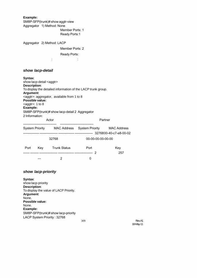
309 Rev.A118-May-11
Example:SM8P-SFP(trunk)# show aggtr-viewAggregator 1) Method: None
Member Ports: 1Ready Ports:1
Aggregator 2) Method: LACPMember Ports: 2Ready Ports:
: :
show lacp-detail
Syntax:show lacp-detail <aggtr>Description:To display the detailed information of the LACP trunk group.Argument:<aggtr>: aggregator, available from 1 to 8Possible value:<aggtr>: 1 to 8Example:SM8P-SFP(trunk)# show lacp-detail 2 Aggregator2 Information:
Actor Partner--------------------------------- ---------------------------------System Priority MAC Address System Priority MAC Address--------------- ----------------- --------------- ----------------- 3276800-40-c7-e8-00-02
32768 00-00-00-00-00-00
Port Key Trunk Status Port Key------ -------- ----------------- --------------- ----------------- 2 257
--- 2 0
show lacp-priority
Syntax:show lacp-priorityDescription:To display the value of LACP Priority.Argument:None.Possible value:None.Example:SM8P-SFP(trunk)# show lacp-priorityLACP System Priority : 32768

Rev.A118-May-11
310
1 None 0 Active 1 Ready2 LACP 1 Active 2 ---
3 LACP 1 Active 3 ---4 LACP 1 Active 4 ---5 LACP 1 Active 5 ---6 LACP 1 Active 6 ---7 LACP 1 Active 7 ---
show status
Syntax:show statusDescription:To display the aggregator status and the settings of each port.Argument:None.Possible value:None.Example:SM8P-SFP(trunk)# show status
Trunk Port Setting Trunk Port Status-----------------------------------------------------------port Method Group Active LACP Aggtregator Status
====== ======== ======= ============= ============= ========
:
vlan
del port-group
Syntax:del port-group <name>Description:To delete the port-based vlan group.Argument:<name>: which vlan group you want to delete.Possible value:<name>: port-vlan nameExample:SM8P-SFP(vlan)# del port-group VLAN-2
del tag-group
Syntax:del tag-group <vid>Description:To delete the tag-based vlan group.Argument:<vid>: which vlan group you want to delete, available from 1 to 4094


Rev.A118-May-11
310
Possible value:<vid>: 1 to 4094Example:SM8P-SFP(vlan)# del tag-group 2
disable drop-untag
Syntax:disable drop-untag <range>Description:Don’t drop the untagged frames.Argument:<range> : which port(s) you want to set, syntax 1,5-7, available from 1 to 8Possible value:<range>: 1 to 8Example:SM8P-SFP(vlan)# disable drop-untag 5-8
disable sym-vlan
Syntax:disable sym-vlan <range>Description:To drop frames from the non-member port.Argument:<range>: which port(s) you want to set, syntax 1,5-7, available from 1 to 8Possible value:<range>: 1 to 8Example:SM8P-SFP(vlan)# disable sym-vlan 5-10
enable drop-untag
Syntax:enable drop-untag <range>Description:To drop the untagged frames.Argument:<range>: which port(s) you want to set, syntax 1,5-7, available from 1 to 8Possible value:<range>: 1 to 8Example:SM8P-SFP(vlan)# enable drop-untag 5-8
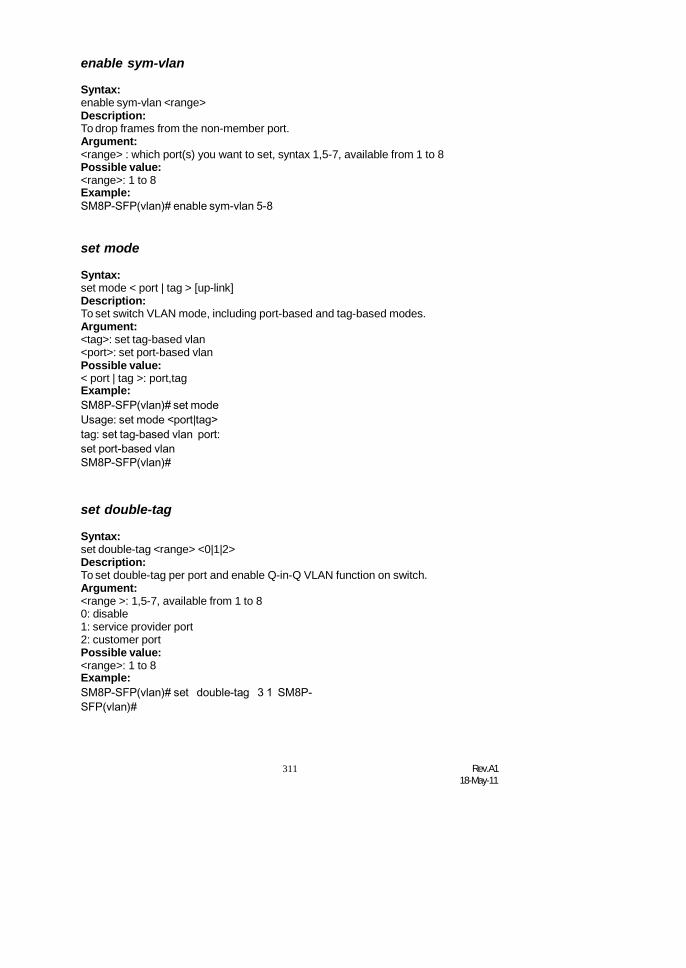
311 Rev.A118-May-11
enable sym-vlan
Syntax:enable sym-vlan <range>Description:To drop frames from the non-member port.Argument:<range> : which port(s) you want to set, syntax 1,5-7, available from 1 to 8Possible value:<range>: 1 to 8Example:SM8P-SFP(vlan)# enable sym-vlan 5-8
set mode
Syntax:set mode < port | tag > [up-link]Description:To set switch VLAN mode, including port-based and tag-based modes.Argument:<tag>: set tag-based vlan<port>: set port-based vlanPossible value:< port | tag >: port,tagExample:SM8P-SFP(vlan)# set modeUsage: set mode <port|tag>tag: set tag-based vlan port:set port-based vlanSM8P-SFP(vlan)#
set double-tag
Syntax:set double-tag <range> <0|1|2>Description:To set double-tag per port and enable Q-in-Q VLAN function on switch.Argument:<range >: 1,5-7, available from 1 to 80: disable1: service provider port2: customer portPossible value:<range>: 1 to 8Example:SM8P-SFP(vlan)# set double-tag 3 1 SM8P-SFP(vlan)#
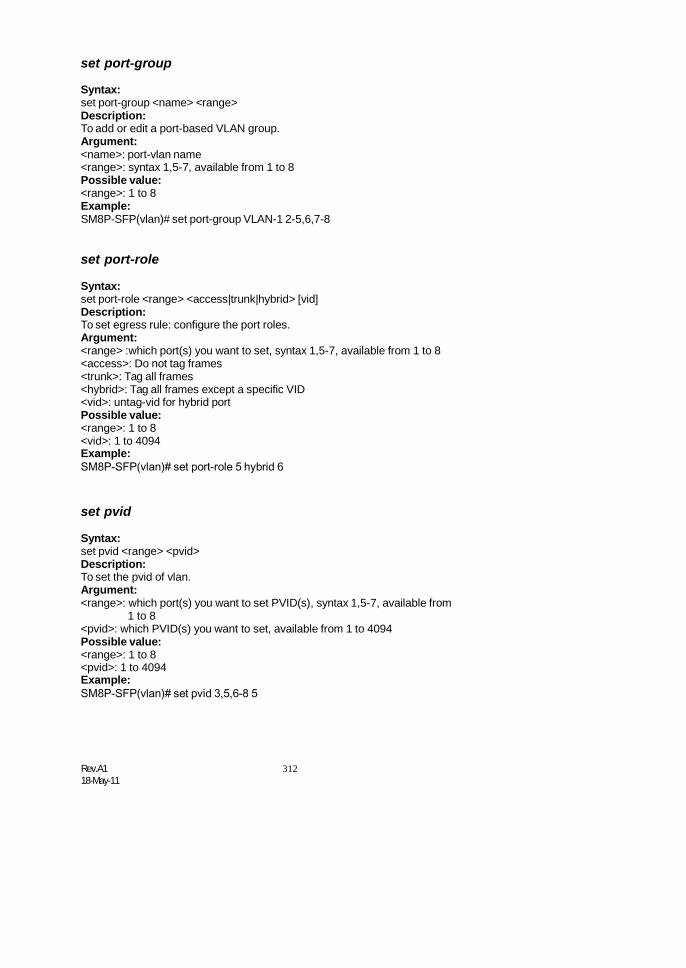
Rev.A118-May-11
312
set port-group
Syntax:set port-group <name> <range>Description:To add or edit a port-based VLAN group.Argument:<name>: port-vlan name<range>: syntax 1,5-7, available from 1 to 8Possible value:<range>: 1 to 8Example:SM8P-SFP(vlan)# set port-group VLAN-1 2-5,6,7-8
set port-role
Syntax:set port-role <range> <access|trunk|hybrid> [vid]Description:To set egress rule: configure the port roles.Argument:<range> :which port(s) you want to set, syntax 1,5-7, available from 1 to 8<access>: Do not tag frames<trunk>: Tag all frames<hybrid>: Tag all frames except a specific VID<vid>: untag-vid for hybrid portPossible value:<range>: 1 to 8<vid>: 1 to 4094Example:SM8P-SFP(vlan)# set port-role 5 hybrid 6
set pvid
Syntax:set pvid <range> <pvid>Description:To set the pvid of vlan.Argument:<range>: which port(s) you want to set PVID(s), syntax 1,5-7, available from
1 to 8<pvid>: which PVID(s) you want to set, available from 1 to 4094Possible value:<range>: 1 to 8<pvid>: 1 to 4094Example:SM8P-SFP(vlan)# set pvid 3,5,6-8 5
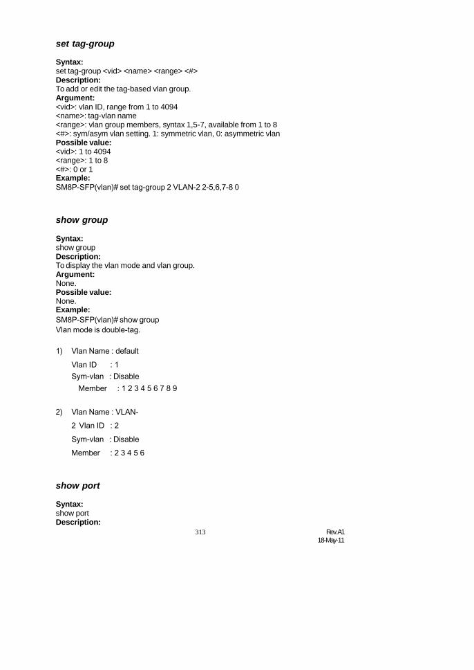
313 Rev.A118-May-11
set tag-group
Syntax:set tag-group <vid> <name> <range> <#>Description:To add or edit the tag-based vlan group.Argument:<vid>: vlan ID, range from 1 to 4094<name>: tag-vlan name<range>: vlan group members, syntax 1,5-7, available from 1 to 8<#>: sym/asym vlan setting. 1: symmetric vlan, 0: asymmetric vlanPossible value:<vid>: 1 to 4094<range>: 1 to 8<#>: 0 or 1Example:SM8P-SFP(vlan)# set tag-group 2 VLAN-2 2-5,6,7-8 0
show group
Syntax:show groupDescription:To display the vlan mode and vlan group.Argument:None.Possible value:None.Example:SM8P-SFP(vlan)# show groupVlan mode is double-tag.
1) Vlan Name : defaultVlan ID : 1Sym-vlan : Disable
Member : 1 2 3 4 5 6 7 8 9
2) Vlan Name : VLAN-2 Vlan ID : 2Sym-vlan : DisableMember : 2 3 4 5 6
show port
Syntax:show portDescription:

Rev.A118-May-11
314
To display pvid, ingress/egress rule.Argument:
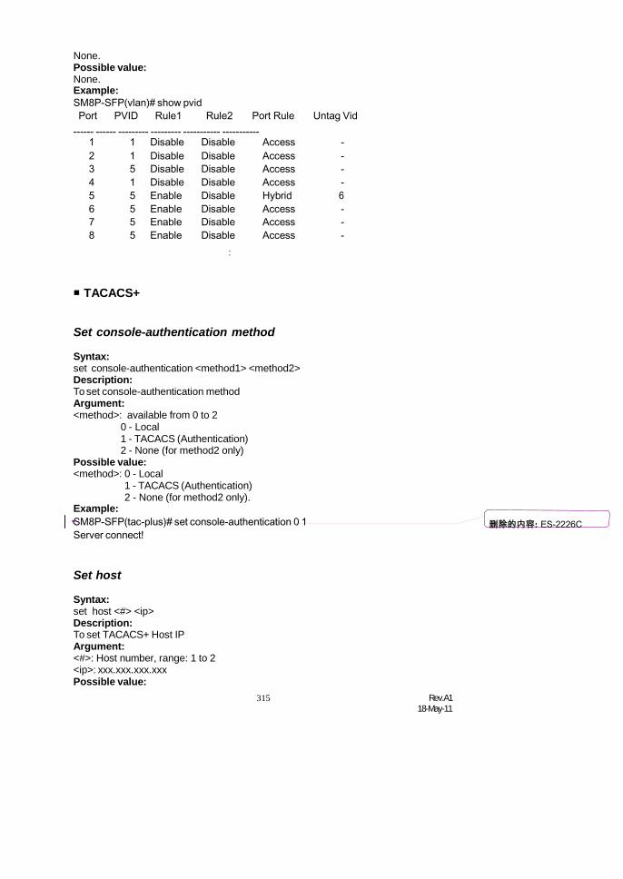
315 Rev.A118-May-11
1 1 Disable Disable Access -2 1 Disable Disable Access -3 5 Disable Disable Access -4 1 Disable Disable Access -5 5 Enable Disable Hybrid 66 5 Enable Disable Access -7 5 Enable Disable Access -8 5 Enable Disable Access -
None.Possible value:None.Example:SM8P-SFP(vlan)# show pvidPort PVID Rule1 Rule2 Port Rule Untag Vid
------ ------ --------- --------- ----------- -----------
:
TACACS+
Set console-authentication method
Syntax:set console-authentication <method1> <method2>Description:To set console-authentication methodArgument:<method>: available from 0 to 2
0 - Local1 - TACACS (Authentication)2 - None (for method2 only)
Possible value:<method>: 0 - Local
1 - TACACS (Authentication)2 - None (for method2 only).
Example:SM8P-SFP(tac-plus)# set console-authentication 0 1Server connect!
Set host
Syntax:set host <#> <ip>Description:To set TACACS+ Host IPArgument:<#>: Host number, range: 1 to 2<ip>: xxx.xxx.xxx.xxxPossible value:
删除的内容: ES-2226C

Rev.A118-May-11
316
<#>: Host number, range: 1 to 2<ip>: xxx.xxx.xxx.xxxExample:SM8P-SFP(tac-plus)# set host 1 192.168.30.200 Serverconnect!
Set key
Syntax:set key <secret-key>Description:To set TACACS+ KeyArgument:<secret-key>: The length of secret-key is from 1 to 31Possible value:<secret-key>: The length of secret-key is from 1 to 31Example:SM8P-SFP(tac-plus)# set key tacacsServer connect!
Set retry
Syntax:set retry <retry>Description:To set retry timeArgument:<retry>: 1-3Possible value:<retry>: 1-3Example:SM8P-SFP(tac-plus)# set retry 1Server connect!
Set telnet-authentication
Syntax:set telnet-authentication <method1> <method2>Description:To set telnet-authentication methodArgument:<method>: available from 0 to 2
0 - Local1 - TACACS (Authentication)2 - None (for method2 only)
Possible value:<method>: available from 0 to 2
0 - Local1 - TACACS (Authentication)

317 Rev.A118-May-11
Example:2 - None (for method2 only)
SM8P-SFP(tac-plus)# set telnet-authentication 0 1Server connect!
Set web-authentication
Syntax:set web-authentication <method1> <method2>Description:To set web-authentication methodArgument:<method>: available from 0 to 2
0 - Local1 - TACACS (Authentication)2 - None (for method2 only)
Possible value:<method>: available from 0 to 2
0 - Local1 - TACACS (Authentication)2 - None (for method2 only)
Example:SM8P-SFP(tac-plus)# set web-authentication 0 1 Serverconnect!
Enable accounting
Syntax:enable accountingDescription:To enable TACACS+ accountingArgument:NonePossible value:NoneExample:SM8P-SFP(tac-plus)# enable accounting Serverconnect!
Enable authorization
Syntax:enable authorizationDescription:To enable TACACS+ AuthorizationArgument:NonePossible value:None

Rev.A118-May-11
318
Example:SM8P-SFP(tac-plus)# enable authorizationServer connect!
Enable fallback-author
Syntax:enable fallback-authorDescription:To enable fallback to Local AuthorizationArgument:NonePossible value:NoneExample:SM8P-SFP(tac-plus)# enable fallback-authorServer connect!
Show authentication
Syntax:show authenticationDescription:To show authentication configArgument:NonePossible value:NoneExample:SM8P-SFP(tac-plus)# show authentication Serverconnect!
Show tac-plus
Syntax:show tac-plusDescription:To show tac-plus configArgument:NonePossible value:NoneExample:SM8P-SFP(tac-plus)#show tac-plusServer connect!

319 Rev.A118-May-11
5. Maintenance5-1. Resolving No Link ConditionThe possible causes for a no link LED status are as follows: The attached device is not powered on The cable may not be the correct type or is faulty The installed building premise cable is faulty The port may be faulty
5-2. Q&A1. Computer A can connect to Computer B, but cannot connect to Computer C
through the Managed Switch. The network device of Computer C may fail to work. Please check the
link/act status of Computer C on the LED indicator. Try another networkdevice on this connection.
The network configuration of Computer C may be something wrong. Pleaseverify the network configuration on Computer C.
2. The uplink connection function fails to work. The connection ports on another must be connection ports. Please check if
connection ports are used on that Managed Switch. Please check the uplink setup of the Managed Switch to verify the uplink
function is enabled.
3. The console interface cannot appear on the console port connection. The COM port default parameters are [Baud Rate: 115200, Data Bits: 8,
Parity Bits: None, Stop Bit: A, Flow Control: None]. Please check the COMport property in the terminal program. And if the parameters are changed,please set the COM configuration to the new setting.
Check the RS-232 cable is connected well on the console port of theManaged Switch and COM port of PC.
Check if the COM of the PC is enabled.
4. How to configure the Managed Switch? The “Hyperterm” is the terminal program in Win95/98/NT. Users can also use
any other terminal programs in Linux/Unix to configure the Managed Switch.Please refer to the user guide of that terminal program. But the COM portparameters (baud rate/ data bits/ parity bits/ flow control) must be the sameas the setting of the console port of the Managed Switch.

Rev.A118-May-11
320
Features
Appendix A TechnicalSpecifications
6 (100/1000M) fiber (SFP) switching ports are compliant with SX/LX/FX.etc-LC. 2 Dual Media TP / (100/1000M) SFP fiber ports are with auto detected function. Non-blocking store-and-forward shared-memory Managed Switched. Supports auto-negotiation for configuring speed, duplex mode. Supports 802.3x flow control for full-duplex ports. Supports collision-based and carrier-based backpressure for half-duplex ports. Any ports can be in disable mode, force mode or auto-polling mode. Supports broadcast storm filtering. Auto-aging with programmable inter-age time. Supports 802.1p Class of Service with 2-level priority queuing. Supports port sniffer function Programmable maximum Ethernet frame length of range from 1518 to 9600
bytes jumbo frame. Supports port-based VLAN, 802.1Q tag-based VLAN. Efficient self-learning and address recognition mechanism enables forwarding
rate at wire speed. Web-based management provides the ability to completely manage the switch
from any web browser. SNMP/Telnet interface delivers complete in-band management. Supports IEEE 802.1d Spanning Tree Protocol. Supports IEEE 802.1w Rapid Spanning Trees. Supports IEEE 802.1s Multiple Spanning Trees. Supports IEEE 802.1X port-based network access control. Supports ACL to classify the ingress packets to do permit/deny, rate limit actions Supports QCL to classify the ingress packets for priority queues assignment Supports IP-MAC Binding function to prevent spoofing attack Supports IP Multicasting to implement IGMP Snooping function. Supports 802.1p Class of Service with 4-level priority queuing. Supports 802.3ad port trunking with flexible load distribution and failover
function. Supports ingress port security mode for VLAN Tagged and Untagged frame
process. Supports SNMPv1/v2c/v3 and RMON sampling with sampled packet error
indication. Supports Power Saving with "ActiPHY Power Management" and "PerfectReach
Power Management" techniques. Supports Link Layer Discovery Protocol (LLDP) Supports SSL and SSH for secure Management Supports TACACS+ for management authentication. Supports Power Saving with "ActiPHY Power Management" and "PerfectReach
Power Management" techniques. Supports Link Layer Discovery Protocol (LLDP, IEEE802.1AB)


Rev.A118-May-11
320
Hardware Specifications
Standard Compliance: IEEE802.3/802.3ab / 802.3z / 802.3u / 802.3x
Network Interface:Configuration Connector Port10/100/1000Mbps TP Jack (RJ-45) TP(RJ-45) 7 to 8
100/1000Mbps SFP Fiber Module SFP 1 to 8
*Port 7, 8 are TP/SFP fiber dual media ports with auto detected function*Optional SFP module supports LC or BiDi LC transceiver
Transmission Mode: 10/100Mbps support full or half duplex1000Mbps support full duplex only
Transmission Speed: 10/100/1000Mbps for TP1000Mbps for Fiber
Full Forwarding/Filtering Packet Rate: PPS (packets per second)
Forwarding Rate Speed1,488,000PPS 1000Mbps148,800PPS 100Mbps14,880PPS 10Mbps
MAC Address and Self-learning: 8K MAC address4K VLAN table entries,
Buffer Memory: Embedded 1392 KB frame buffer Flow Control: IEEE802.3x compliant for full duplex
Backpressure flow control for half duplex Cable and Maximum Length:
TP Cat. 5 UTP cable, up to 100m
1000Base-SX Up to 220/275/500/550m,which depends on Multi-Mode Fiber type
1000Base-LX Single-Mode Fiber, up to10/30/50Km1000Base-LX WDM (BiDi) Single-Mode Single Fiber, up to 20Km
Diagnostic LED:
System LED : PowerPer Port LED:
1 to 8100/1000 Dual Speed SFP Port : LINK/ACT, 100/1000M
10/100/1000M TP Port 7,8 : TP(LINK/ACT), Speed

321 Rev.A118-May-11
Power Requirement : AC Line
Voltage : 100240 VFrequency : 5060 HzConsumption : 40W
Ambient Temperature : 0to 40C Humidity : 5% to 90%Dimensions : 44(H) 280(W) 166(D) mm Comply with FCC Part 15 Class A & CE Mark Approval
ManagementSoftwareSpecifications
System Configuration
Auto-negotiation support on 8-Port 100/1000 DualSpeed SFP ports, Web browser or consoleinterface can set transmission speed(10/100/1000Mbps) and operation mode (Full/Halfduplex) on each port, enable/disable any port, setVLAN group, set Trunk Connection.
Management Agent SNMP support; MIB II, Bridge MIB, RMON MIBNetworking ConvergenceAlgorithm
IEEE 802.1D Spanning TreeIEEE 802.1w Rapid Spanning TreeIEEE 802.1s Multiple Spanning Tree
VLAN Function Port-Base / 802.1Q-Tagged, allowed up to 4Kactive VLANs in one switch.
Trunk Function Ports trunk connections allowed
IGMP IP Multicast Filtering by passively snoopingon the IGMP Query.
Bandwidth Control Supports by-port Egress/Ingress rate control
Quality of Service (QoS)
Referred as Class of Service (CoS) by theIEEE 802.1P standard ,Classification of packetpriority can be based on either a VLAN tag onpacket or a user-definedPer port QoS.Two queues per portIP TOS ClassificationTCP/UDP Port ClassificationIP DiffServe Classification
Security Limit number of MAC addresses learned perport static MAC addresses stay in the filtering table.IEEE802.1X Port AuthenticationDHCP SnoopinggIP-MAC Port BindingACLs
Internetworking Protocol
IP Multicast Filtering by passively snoopingon the IGMP Query.IP Multicast : IGMP Snooping
Maximum of 1024 active entries of Group
Network Management
One RJ-45 port as local control consoleTelnet remote control consoleSNMP agent : MIB-2 (RFC 1213)
Bridge MIB (RFC 1493)RMON MIB (RFC 1757)-statisticsEthernet-like MIB (RFC 1643)
Web browser support based on HTTP Serverand CGI parser TFTP software-upgrade capability.
Note: Any specification is subject to change without notice.
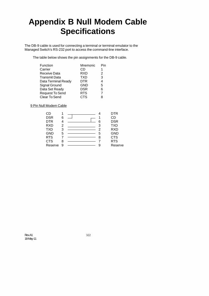
Rev.A118-May-11
322
Appendix B Null Modem CableSpecifications
The DB-9 cable is used for connecting a terminal or terminal emulator to theManaged Switch’s RS-232 port to access the command-line interface.
The table below shows the pin assignments for the DB-9 cable.
FunctionCarrier
MnemonicCD
Pin1
Receive Data RXD 2Transmit Data TXD 3Data Terminal Ready DTR 4Signal Ground GND 5Data Set Ready DSR 6Request To Send RTS 7Clear To Send CTS 8
9 Pin Null Modem Cable
CD 1 4 DTRDSR 6 1 CDDTR 4 6 DSRRXD 2 3 TXDTXD 3 2 RXDGND 5 5 GNDRTS 7 8 CTSCTS 8 7 RTSReserve 9 9 Reserve
