instruction harmony series - bailey net 90 and infi 90
TRANSCRIPT

InstructionHarmony Series
Simulation BlockSIM-100

WBPEEUI210507A0
Preface
The SIM-100 Harmony Simulation Block is one part of a fully stimulated control simulator available for the Symphony Enterprise Management and Control System. The SIM-100 block along with Simulation LAN and API software, a Harmony controller, and a Conductor human system interface combine to create the Harmony stimulated simulation system. This simulation system is a high fidelity training simulator designed for operator and maintenance training, control logic and opera-tor validation, and control logic development and checkout.
This instruction explains SIM-100 block features, specifica-tions, and operation. It also includes installation, trouble-shooting, maintenance, and replacement procedures for the block.

WBPEEUI210507A0
List of Effective Pages
NOTE: Changed text or tables are indicated by a vertical bar adjacent to the changed area. Changed fig-ures are indicated by a vertical bar next to the figure caption. The date appears beside the page number.
Total number of pages in this instruction is 102, consisting of the following:
Preface OriginalList of Effective Pages Original
iii through x Original1-1 through 1-14 Original2-1 through 2-12 Original3-1 through 3-3 Original4-1 through 4-6 Original5-1 through 5-6 Original6-1 through 6-2 Original7-1 through 7-2 Original8-1 through 8-2 OriginalA-1 through A-4 OriginalB-1 through B-3 Original
PR1-1 through PR1-3 OriginalPR2-1 through PR2-4 OriginalPR3-1 through PR3-2 OriginalPR4-1 through PR4-2 OriginalPR5-1 through PR5-5 OriginalPR6-1 through PR6-3 OriginalPR7-1 through PR7-5 OriginalPR8-1 through PR8-7 OriginalPR9-1 Original
PR10-1 through PR10-2 OriginalPR11-1 through PR11-2 OriginalIndex-1 through Index-2 Original
WBPEEUI210507A0 iii
Table of Contents
Section 1 Introduction ..................................................................................................1-1Overview .................................................................................................................. 1-1
Harmony Controller.............................................................................................. 1-3Hnet................................................................................................................. 1-4I/O Expander Bus ............................................................................................ 1-5
Simulation Block.................................................................................................. 1-5Simulation LAN.................................................................................................... 1-6
Compatibility ........................................................................................................... 1-6Features and Benefits .............................................................................................. 1-6Intended User .......................................................................................................... 1-7Instruction Content.................................................................................................. 1-7How to Use this Instruction...................................................................................... 1-8Document Conventions ............................................................................................ 1-9Glossary of Terms and Abbreviations........................................................................ 1-9Reference Documents............................................................................................. 1-10Abbreviated Harmony Nomenclature ...................................................................... 1-11Related Nomenclature ............................................................................................ 1-11Design Standards................................................................................................... 1-12Specifications......................................................................................................... 1-13
Section 2 Description and Operation .........................................................................2-1Introduction............................................................................................................. 2-1Description .............................................................................................................. 2-1
Module................................................................................................................. 2-2Central Processing Unit .................................................................................... 2-3Memory ............................................................................................................ 2-5Hnet Interface................................................................................................... 2-5Machine Fault Timer ........................................................................................ 2-6Block Power...................................................................................................... 2-6LED Drivers and Status LEDs........................................................................... 2-7Switches........................................................................................................... 2-8Stop/Reset ....................................................................................................... 2-8
Base..................................................................................................................... 2-8Hardware Keying.................................................................................................. 2-9
Mounting Hardware ................................................................................................. 2-9Column Mounting Bar.......................................................................................... 2-9Block Mounting Column..................................................................................... 2-10Signal Distribution ............................................................................................. 2-11

iv WBPEEUI210507A0
Table of Contents (continued)
Section 3 Installation ....................................................................................................3-1Introduction .............................................................................................................3-1Special Handling ......................................................................................................3-1Unpacking and Inspection ........................................................................................3-2Installation and Connection Sequence ......................................................................3-2
Section 4 Operating Procedures .................................................................................4-1Introduction .............................................................................................................4-1Front Panel...............................................................................................................4-1
Operating Mode - Normal and Fault ......................................................................4-1Block Status .........................................................................................................4-1Block Power..........................................................................................................4-3Communication Status .........................................................................................4-3ID Labels ..............................................................................................................4-3
Module Rear Panel....................................................................................................4-5Operation .................................................................................................................4-5
Startup.................................................................................................................4-5Stop/Reset ...........................................................................................................4-6
Section 5 Troubleshooting ..........................................................................................5-1Introduction .............................................................................................................5-1Troubleshooting Procedures......................................................................................5-1Operating Mode - Normal and Fault LEDs.................................................................5-1Block Power LEDs ....................................................................................................5-1Block Status LEDs....................................................................................................5-3Diagnostics ..............................................................................................................5-5SIM-100 Module Connectors (P1, P4, P5, P7).............................................................5-5
Section 6 Maintenance .................................................................................................6-1Introduction .............................................................................................................6-1Preventive Maintenance Schedule .............................................................................6-1
Section 7 Repair and Replacement .............................................................................7-1Introduction .............................................................................................................7-1Repair ......................................................................................................................7-1Replacement.............................................................................................................7-1
Section 8 Replacement and Spare Parts ....................................................................8-1Introduction .............................................................................................................8-1Block Nomenclature .................................................................................................8-1
WBPEEUI210507A0 v
Table of Contents (continued)
Section 8 Replacement and Spare Parts (continued)Cable Nomenclature................................................................................................. 8-1Miscellaneous Nomenclature.................................................................................... 8-2Miscellaneous Parts ................................................................................................. 8-2
Appendix A Hardware Drawings ................................................................................ A-1Introduction.............................................................................................................A-1SIM-100 Block .........................................................................................................A-1Block Mounting Column ..........................................................................................A-3Column Mounting Bar..............................................................................................A-4
Appendix B Firmware Upgrade .................................................................................. B-1Introduction.............................................................................................................B-1Procedure ................................................................................................................B-1
List of ProceduresNo. Title
PR1 Column Mounting Bar InstallationPR2 Block Mounting Column InstallationPR3 SIM-100 Base InstallationPR4 SIM-100 Module InstallationPR5 SIM-100 SetupPR6 24 VDC Power ConnectionPR7 Hnet ConnectionPR8 Simulation LAN ConnectionPR9 Connections CheckPR10 SIM-100 Module RemovalPR11 SIM-100 Base Removal

vi WBPEEUI210507A0
List of FiguresNo. Title Page1-1. Harmony Stimulated Simulation Architecture (Simulated I/O) ...................1-21-2. Harmony Stimulated Simulation Architecture
(Simulated I/O and Real I/O).....................................................................1-32-1. SIM-100 Block...........................................................................................2-22-2. Configuration Switch and Jumper Access ..................................................2-32-3. Functional Block Diagram .........................................................................2-42-4. Hnet Interface ...........................................................................................2-52-5. Block Power...............................................................................................2-72-6. SIM-100 Base............................................................................................2-82-7. Block Mounting Hardware .......................................................................2-102-8. MCL-111 Block Mounting Column (Hnet Cover Plate Removed) ................2-113-1. Installation and Connection Flowchart.......................................................3-34-1. SIM-100 Block Front Panel ........................................................................4-24-2. SIM-100 Module Rear Panel.......................................................................4-57-1. Replacement Flowchart .............................................................................7-2A-1. SIM-100 Module ....................................................................................... A-1A-2. SIM-100 Base........................................................................................... A-2A-3. Block Mounting Column ........................................................................... A-3A-4. Column Mounting Bar .............................................................................. A-4B-1. RS-232-C Diagnostic Port Interconnection ................................................ B-1PR1-1. Column Mounting Bar Spacing ............................................................. PR1-2PR1-2. Column Mounting Bar Attachment ....................................................... PR1-3PR2-1. Hnet Cover Plate Removal ..................................................................... PR2-2PR2-2. Single Column Attachment ................................................................... PR2-3PR2-3. Stacked Column Attachment ................................................................ PR2-4PR3-1. SIM-100 Base Attachment .................................................................... PR3-2PR4-1. SIM-100 Module Attachment ................................................................ PR4-2PR5-1. SIM-100 Base....................................................................................... PR5-3PR5-2. SIM-100 Module Switch and Jumper Access ......................................... PR5-4PR5-3. SIM-100 Module Board Layout ............................................................. PR5-5PR6-1. 24 VDC Power Connectors .................................................................... PR6-2PR7-1. Single MCL-111 Column Hnet Connections........................................... PR7-2PR7-2. Multiple MCL-111 Column Hnet Connections ....................................... PR7-3PR7-3. MCL-111 to MCL-?10 Column Hnet Connections .................................. PR7-3PR7-4. MCL-111 to MCL-?20 Column Hnet Connections .................................. PR7-4PR7-5. MSC-TER2 Hnet Terminator ................................................................. PR7-4PR7-6. Hnet Cover Plate Installation ................................................................ PR7-5PR8-1. 10BaseT Example Connection............................................................... PR8-3PR8-2. SIM-100 Base....................................................................................... PR8-4PR8-3. 10Base2 Example Connection............................................................... PR8-5PR8-4. 10Base5 Example Connection............................................................... PR8-6PR8-5. 10BaseFL Example Connection............................................................. PR8-7PR10-1. SIM-100 Module Removal ................................................................... PR10-2

WBPEEUI210507A0 vii
List of Figures (continued)
No. Title PagePR11-1. SIM-100 Base Removal ....................................................................... PR11-2
List of TablesNo. Title Page
1-1. Glossary of Terms and Abbreviations....................................................... 1-101-2. Reference Documents.............................................................................. 1-101-3. Abbreviated Nomenclature ...................................................................... 1-111-4. Related Nomenclature ............................................................................. 1-111-5. Design Standards.................................................................................... 1-121-6. SIM-100 Block Specifications .................................................................. 1-131-7. Environmental Specifications .................................................................. 1-144-1. Operating Mode - Normal and Fault LEDs ................................................. 4-24-2. Normal Operating Mode Status Codes ....................................................... 4-34-3. Communication Status LEDs .................................................................... 4-44-4. LEDs - Startup Sequence .......................................................................... 4-65-1. Operating Mode - Normal and Fault LEDs ................................................. 5-25-2. Block Power A and B LEDs........................................................................ 5-25-3. Status Codes............................................................................................. 5-35-4. P1 Power Pins ........................................................................................... 5-55-5. P4 Ethernet Pins ....................................................................................... 5-65-6. P5 Communication Pins ............................................................................ 5-65-7. P7 RS-232-C Port Pins .............................................................................. 5-66-1. Preventive Maintenance Schedule.............................................................. 6-28-1. Simulation Block Nomenclature ................................................................ 8-18-2. Power Cable Nomenclature........................................................................ 8-18-3. Miscellaneous Nomenclature..................................................................... 8-28-4. Miscellaneous Parts .................................................................................. 8-2B-1. LEDs - Firmware Upgrade .........................................................................B-3PR5-1. Jumper E1 (Base) - Heartbeat ...............................................................PR5-1PR5-2. Switch SW5 (Module) - Special Operations.............................................PR5-1PR5-3. Switches SW1 through SW4 (Module) - Example IP Address Settings .....PR5-2

viii WBPEEUI210507A0
Safety Summary
Electrostatic Sensitive DeviceDevices labeled with this symbol require special handling precau-tions as described in the installation section.
GENERALWARNINGS
Equipment EnvironmentAll components, whether in transportation, operation or storage,must be in a noncorrosive environment.
Electrical Shock Hazard During MaintenanceDisconnect power or take precautions to insure that contact withenergized parts is avoided when servicing.
SPECIFICWARNINGS
A SIM-100 module should not be inserted or removed with powerapplied when located in a class I, division 2 hazardous locationunless the area is known to be nonhazardous. (p. 2-2, 3-2, 7-1,PR4-1, PR10-1)
Turn off all power before attempting the connections check mainte-nance procedure. Failure to do so could result in severe or fatalshock, or equipment damage. (p. PR9-1)

WBPEEUI210507A0 ix
Support Services
ABB will provide assistance in the operation and repair of its products. Requests for sales or application services should be made to your nearest sales or service office. ABB can also pro-vide installation, repair and maintenance contract services.
When ordering parts, use nomenclature or part numbers and part descriptions from equipment manuals. Parts without a description must be ordered from the nearest sales or service office. Recommended spare parts lists, including prices are available through the nearest sales or service office.
ABB has modern training facilities available for training your personnel. On-site training is also available. Contact your nearest ABB sales office for specific information and scheduling.
Additional copies of this instruction, or other instructions, can be obtained from the nearest ABB sales office at a reasonable charge.

x WBPEEUI210507A0
Trademarks and Registrations
Registrations and trademarks used in this document include:
™ Ethernet Trademark of Xerox Corporation.® INFI 90 Registered trademark of Elsag Bailey Process Automation

WBPEEUI210507A0
Preface
The SIM-100 Harmony Simulation Block is one part of a fully stimulated control simulator available for the Symphony Enterprise Management and Control System. The SIM-100 block along with Simulation LAN and API software, a Harmony controller, and a Conductor human system interface combine to create the Harmony stimulated simulation system. This simulation system is a high fidelity training simulator designed for operator and maintenance training, control logic and opera-tor validation, and control logic development and checkout.
This instruction explains SIM-100 block features, specifica-tions, and operation. It also includes installation, trouble-shooting, maintenance, and replacement procedures for the block.

WBPEEUI210507A0
List of Effective Pages
NOTE: Changed text or tables are indicated by a vertical bar adjacent to the changed area. Changed fig-ures are indicated by a vertical bar next to the figure caption. The date appears beside the page number.
Total number of pages in this instruction is 102, consisting of the following:
Preface OriginalList of Effective Pages Original
iii through x Original1-1 through 1-14 Original2-1 through 2-12 Original3-1 through 3-3 Original4-1 through 4-6 Original5-1 through 5-6 Original6-1 through 6-2 Original7-1 through 7-2 Original8-1 through 8-2 OriginalA-1 through A-4 OriginalB-1 through B-3 Original
PR1-1 through PR1-3 OriginalPR2-1 through PR2-4 OriginalPR3-1 through PR3-2 OriginalPR4-1 through PR4-2 OriginalPR5-1 through PR5-5 OriginalPR6-1 through PR6-3 OriginalPR7-1 through PR7-5 OriginalPR8-1 through PR8-7 OriginalPR9-1 Original
PR10-1 through PR10-2 OriginalPR11-1 through PR11-2 OriginalIndex-1 through Index-2 Original

WBPEEUI210507A0 iii
Table of Contents
Section 1 Introduction ..................................................................................................1-1Overview .................................................................................................................. 1-1
Harmony Controller.............................................................................................. 1-3Hnet................................................................................................................. 1-4I/O Expander Bus ............................................................................................ 1-5
Simulation Block.................................................................................................. 1-5Simulation LAN.................................................................................................... 1-6
Compatibility ........................................................................................................... 1-6Features and Benefits .............................................................................................. 1-6Intended User .......................................................................................................... 1-7Instruction Content.................................................................................................. 1-7How to Use this Instruction...................................................................................... 1-8Document Conventions ............................................................................................ 1-9Glossary of Terms and Abbreviations........................................................................ 1-9Reference Documents............................................................................................. 1-10Abbreviated Harmony Nomenclature ...................................................................... 1-11Related Nomenclature ............................................................................................ 1-11Design Standards................................................................................................... 1-12Specifications......................................................................................................... 1-13
Section 2 Description and Operation .........................................................................2-1Introduction............................................................................................................. 2-1Description .............................................................................................................. 2-1
Module................................................................................................................. 2-2Central Processing Unit .................................................................................... 2-3Memory ............................................................................................................ 2-5Hnet Interface................................................................................................... 2-5Machine Fault Timer ........................................................................................ 2-6Block Power...................................................................................................... 2-6LED Drivers and Status LEDs........................................................................... 2-7Switches........................................................................................................... 2-8Stop/Reset ....................................................................................................... 2-8
Base..................................................................................................................... 2-8Hardware Keying.................................................................................................. 2-9
Mounting Hardware ................................................................................................. 2-9Column Mounting Bar.......................................................................................... 2-9Block Mounting Column..................................................................................... 2-10Signal Distribution ............................................................................................. 2-11

iv WBPEEUI210507A0
Table of Contents (continued)
Section 3 Installation ....................................................................................................3-1Introduction .............................................................................................................3-1Special Handling ......................................................................................................3-1Unpacking and Inspection ........................................................................................3-2Installation and Connection Sequence ......................................................................3-2
Section 4 Operating Procedures .................................................................................4-1Introduction .............................................................................................................4-1Front Panel...............................................................................................................4-1
Operating Mode - Normal and Fault ......................................................................4-1Block Status .........................................................................................................4-1Block Power..........................................................................................................4-3Communication Status .........................................................................................4-3ID Labels ..............................................................................................................4-3
Module Rear Panel....................................................................................................4-5Operation .................................................................................................................4-5
Startup.................................................................................................................4-5Stop/Reset ...........................................................................................................4-6
Section 5 Troubleshooting ..........................................................................................5-1Introduction .............................................................................................................5-1Troubleshooting Procedures......................................................................................5-1Operating Mode - Normal and Fault LEDs.................................................................5-1Block Power LEDs ....................................................................................................5-1Block Status LEDs....................................................................................................5-3Diagnostics ..............................................................................................................5-5SIM-100 Module Connectors (P1, P4, P5, P7).............................................................5-5
Section 6 Maintenance .................................................................................................6-1Introduction .............................................................................................................6-1Preventive Maintenance Schedule .............................................................................6-1
Section 7 Repair and Replacement .............................................................................7-1Introduction .............................................................................................................7-1Repair ......................................................................................................................7-1Replacement.............................................................................................................7-1
Section 8 Replacement and Spare Parts ....................................................................8-1Introduction .............................................................................................................8-1Block Nomenclature .................................................................................................8-1

WBPEEUI210507A0 v
Table of Contents (continued)
Section 8 Replacement and Spare Parts (continued)Cable Nomenclature................................................................................................. 8-1Miscellaneous Nomenclature.................................................................................... 8-2Miscellaneous Parts ................................................................................................. 8-2
Appendix A Hardware Drawings ................................................................................ A-1Introduction.............................................................................................................A-1SIM-100 Block .........................................................................................................A-1Block Mounting Column ..........................................................................................A-3Column Mounting Bar..............................................................................................A-4
Appendix B Firmware Upgrade .................................................................................. B-1Introduction.............................................................................................................B-1Procedure ................................................................................................................B-1
List of ProceduresNo. Title
PR1 Column Mounting Bar InstallationPR2 Block Mounting Column InstallationPR3 SIM-100 Base InstallationPR4 SIM-100 Module InstallationPR5 SIM-100 SetupPR6 24 VDC Power ConnectionPR7 Hnet ConnectionPR8 Simulation LAN ConnectionPR9 Connections CheckPR10 SIM-100 Module RemovalPR11 SIM-100 Base Removal

vi WBPEEUI210507A0
List of FiguresNo. Title Page1-1. Harmony Stimulated Simulation Architecture (Simulated I/O) ...................1-21-2. Harmony Stimulated Simulation Architecture
(Simulated I/O and Real I/O).....................................................................1-32-1. SIM-100 Block...........................................................................................2-22-2. Configuration Switch and Jumper Access ..................................................2-32-3. Functional Block Diagram .........................................................................2-42-4. Hnet Interface ...........................................................................................2-52-5. Block Power...............................................................................................2-72-6. SIM-100 Base............................................................................................2-82-7. Block Mounting Hardware .......................................................................2-102-8. MCL-111 Block Mounting Column (Hnet Cover Plate Removed) ................2-113-1. Installation and Connection Flowchart.......................................................3-34-1. SIM-100 Block Front Panel ........................................................................4-24-2. SIM-100 Module Rear Panel.......................................................................4-57-1. Replacement Flowchart .............................................................................7-2A-1. SIM-100 Module ....................................................................................... A-1A-2. SIM-100 Base........................................................................................... A-2A-3. Block Mounting Column ........................................................................... A-3A-4. Column Mounting Bar .............................................................................. A-4B-1. RS-232-C Diagnostic Port Interconnection ................................................ B-1PR1-1. Column Mounting Bar Spacing ............................................................. PR1-2PR1-2. Column Mounting Bar Attachment ....................................................... PR1-3PR2-1. Hnet Cover Plate Removal ..................................................................... PR2-2PR2-2. Single Column Attachment ................................................................... PR2-3PR2-3. Stacked Column Attachment ................................................................ PR2-4PR3-1. SIM-100 Base Attachment .................................................................... PR3-2PR4-1. SIM-100 Module Attachment ................................................................ PR4-2PR5-1. SIM-100 Base....................................................................................... PR5-3PR5-2. SIM-100 Module Switch and Jumper Access ......................................... PR5-4PR5-3. SIM-100 Module Board Layout ............................................................. PR5-5PR6-1. 24 VDC Power Connectors .................................................................... PR6-2PR7-1. Single MCL-111 Column Hnet Connections........................................... PR7-2PR7-2. Multiple MCL-111 Column Hnet Connections ....................................... PR7-3PR7-3. MCL-111 to MCL-?10 Column Hnet Connections .................................. PR7-3PR7-4. MCL-111 to MCL-?20 Column Hnet Connections .................................. PR7-4PR7-5. MSC-TER2 Hnet Terminator ................................................................. PR7-4PR7-6. Hnet Cover Plate Installation ................................................................ PR7-5PR8-1. 10BaseT Example Connection............................................................... PR8-3PR8-2. SIM-100 Base....................................................................................... PR8-4PR8-3. 10Base2 Example Connection............................................................... PR8-5PR8-4. 10Base5 Example Connection............................................................... PR8-6PR8-5. 10BaseFL Example Connection............................................................. PR8-7PR10-1. SIM-100 Module Removal ................................................................... PR10-2
WBPEEUI210507A0 vii
List of Figures (continued)
No. Title PagePR11-1. SIM-100 Base Removal ....................................................................... PR11-2
List of TablesNo. Title Page
1-1. Glossary of Terms and Abbreviations....................................................... 1-101-2. Reference Documents.............................................................................. 1-101-3. Abbreviated Nomenclature ...................................................................... 1-111-4. Related Nomenclature ............................................................................. 1-111-5. Design Standards.................................................................................... 1-121-6. SIM-100 Block Specifications .................................................................. 1-131-7. Environmental Specifications .................................................................. 1-144-1. Operating Mode - Normal and Fault LEDs ................................................. 4-24-2. Normal Operating Mode Status Codes ....................................................... 4-34-3. Communication Status LEDs .................................................................... 4-44-4. LEDs - Startup Sequence .......................................................................... 4-65-1. Operating Mode - Normal and Fault LEDs ................................................. 5-25-2. Block Power A and B LEDs........................................................................ 5-25-3. Status Codes............................................................................................. 5-35-4. P1 Power Pins ........................................................................................... 5-55-5. P4 Ethernet Pins ....................................................................................... 5-65-6. P5 Communication Pins ............................................................................ 5-65-7. P7 RS-232-C Port Pins .............................................................................. 5-66-1. Preventive Maintenance Schedule.............................................................. 6-28-1. Simulation Block Nomenclature ................................................................ 8-18-2. Power Cable Nomenclature........................................................................ 8-18-3. Miscellaneous Nomenclature..................................................................... 8-28-4. Miscellaneous Parts .................................................................................. 8-2B-1. LEDs - Firmware Upgrade .........................................................................B-3PR5-1. Jumper E1 (Base) - Heartbeat ...............................................................PR5-1PR5-2. Switch SW5 (Module) - Special Operations.............................................PR5-1PR5-3. Switches SW1 through SW4 (Module) - Example IP Address Settings .....PR5-2

viii WBPEEUI210507A0
Safety Summary
Electrostatic Sensitive DeviceDevices labeled with this symbol require special handling precau-tions as described in the installation section.
GENERALWARNINGS
Equipment EnvironmentAll components, whether in transportation, operation or storage,must be in a noncorrosive environment.
Electrical Shock Hazard During MaintenanceDisconnect power or take precautions to insure that contact withenergized parts is avoided when servicing.
SPECIFICWARNINGS
A SIM-100 module should not be inserted or removed with powerapplied when located in a class I, division 2 hazardous locationunless the area is known to be nonhazardous. (p. 2-2, 3-2, 7-1,PR4-1, PR10-1)
Turn off all power before attempting the connections check mainte-nance procedure. Failure to do so could result in severe or fatalshock, or equipment damage. (p. PR9-1)

WBPEEUI210507A0 ix
Support Services
ABB will provide assistance in the operation and repair of its products. Requests for sales or application services should be made to your nearest sales or service office. ABB can also pro-vide installation, repair and maintenance contract services.
When ordering parts, use nomenclature or part numbers and part descriptions from equipment manuals. Parts without a description must be ordered from the nearest sales or service office. Recommended spare parts lists, including prices are available through the nearest sales or service office.
ABB has modern training facilities available for training your personnel. On-site training is also available. Contact your nearest ABB sales office for specific information and scheduling.
Additional copies of this instruction, or other instructions, can be obtained from the nearest ABB sales office at a reasonable charge.

x WBPEEUI210507A0
Trademarks and Registrations
Registrations and trademarks used in this document include:
™ Ethernet Trademark of Xerox Corporation.® INFI 90 Registered trademark of Elsag Bailey Process Automation

WBPEEUI210507A0
Preface
The SIM-100 Harmony Simulation Block is one part of a fully stimulated control simulator available for the Symphony Enterprise Management and Control System. The SIM-100 block along with Simulation LAN and API software, a Harmony controller, and a Conductor human system interface combine to create the Harmony stimulated simulation system. This simulation system is a high fidelity training simulator designed for operator and maintenance training, control logic and opera-tor validation, and control logic development and checkout.
This instruction explains SIM-100 block features, specifica-tions, and operation. It also includes installation, trouble-shooting, maintenance, and replacement procedures for the block.

WBPEEUI210507A0
List of Effective Pages
NOTE: Changed text or tables are indicated by a vertical bar adjacent to the changed area. Changed fig-ures are indicated by a vertical bar next to the figure caption. The date appears beside the page number.
Total number of pages in this instruction is 102, consisting of the following:
Preface OriginalList of Effective Pages Original
iii through x Original1-1 through 1-14 Original2-1 through 2-12 Original3-1 through 3-3 Original4-1 through 4-6 Original5-1 through 5-6 Original6-1 through 6-2 Original7-1 through 7-2 Original8-1 through 8-2 OriginalA-1 through A-4 OriginalB-1 through B-3 Original
PR1-1 through PR1-3 OriginalPR2-1 through PR2-4 OriginalPR3-1 through PR3-2 OriginalPR4-1 through PR4-2 OriginalPR5-1 through PR5-5 OriginalPR6-1 through PR6-3 OriginalPR7-1 through PR7-5 OriginalPR8-1 through PR8-7 OriginalPR9-1 Original
PR10-1 through PR10-2 OriginalPR11-1 through PR11-2 OriginalIndex-1 through Index-2 Original

WBPEEUI210507A0 iii
Table of Contents
Section 1 Introduction ..................................................................................................1-1Overview .................................................................................................................. 1-1
Harmony Controller.............................................................................................. 1-3Hnet................................................................................................................. 1-4I/O Expander Bus ............................................................................................ 1-5
Simulation Block.................................................................................................. 1-5Simulation LAN.................................................................................................... 1-6
Compatibility ........................................................................................................... 1-6Features and Benefits .............................................................................................. 1-6Intended User .......................................................................................................... 1-7Instruction Content.................................................................................................. 1-7How to Use this Instruction...................................................................................... 1-8Document Conventions ............................................................................................ 1-9Glossary of Terms and Abbreviations........................................................................ 1-9Reference Documents............................................................................................. 1-10Abbreviated Harmony Nomenclature ...................................................................... 1-11Related Nomenclature ............................................................................................ 1-11Design Standards................................................................................................... 1-12Specifications......................................................................................................... 1-13
Section 2 Description and Operation .........................................................................2-1Introduction............................................................................................................. 2-1Description .............................................................................................................. 2-1
Module................................................................................................................. 2-2Central Processing Unit .................................................................................... 2-3Memory ............................................................................................................ 2-5Hnet Interface................................................................................................... 2-5Machine Fault Timer ........................................................................................ 2-6Block Power...................................................................................................... 2-6LED Drivers and Status LEDs........................................................................... 2-7Switches........................................................................................................... 2-8Stop/Reset ....................................................................................................... 2-8
Base..................................................................................................................... 2-8Hardware Keying.................................................................................................. 2-9
Mounting Hardware ................................................................................................. 2-9Column Mounting Bar.......................................................................................... 2-9Block Mounting Column..................................................................................... 2-10Signal Distribution ............................................................................................. 2-11
iv WBPEEUI210507A0
Table of Contents (continued)
Section 3 Installation ....................................................................................................3-1Introduction .............................................................................................................3-1Special Handling ......................................................................................................3-1Unpacking and Inspection ........................................................................................3-2Installation and Connection Sequence ......................................................................3-2
Section 4 Operating Procedures .................................................................................4-1Introduction .............................................................................................................4-1Front Panel...............................................................................................................4-1
Operating Mode - Normal and Fault ......................................................................4-1Block Status .........................................................................................................4-1Block Power..........................................................................................................4-3Communication Status .........................................................................................4-3ID Labels ..............................................................................................................4-3
Module Rear Panel....................................................................................................4-5Operation .................................................................................................................4-5
Startup.................................................................................................................4-5Stop/Reset ...........................................................................................................4-6
Section 5 Troubleshooting ..........................................................................................5-1Introduction .............................................................................................................5-1Troubleshooting Procedures......................................................................................5-1Operating Mode - Normal and Fault LEDs.................................................................5-1Block Power LEDs ....................................................................................................5-1Block Status LEDs....................................................................................................5-3Diagnostics ..............................................................................................................5-5SIM-100 Module Connectors (P1, P4, P5, P7).............................................................5-5
Section 6 Maintenance .................................................................................................6-1Introduction .............................................................................................................6-1Preventive Maintenance Schedule .............................................................................6-1
Section 7 Repair and Replacement .............................................................................7-1Introduction .............................................................................................................7-1Repair ......................................................................................................................7-1Replacement.............................................................................................................7-1
Section 8 Replacement and Spare Parts ....................................................................8-1Introduction .............................................................................................................8-1Block Nomenclature .................................................................................................8-1

WBPEEUI210507A0 v
Table of Contents (continued)
Section 8 Replacement and Spare Parts (continued)Cable Nomenclature................................................................................................. 8-1Miscellaneous Nomenclature.................................................................................... 8-2Miscellaneous Parts ................................................................................................. 8-2
Appendix A Hardware Drawings ................................................................................ A-1Introduction.............................................................................................................A-1SIM-100 Block .........................................................................................................A-1Block Mounting Column ..........................................................................................A-3Column Mounting Bar..............................................................................................A-4
Appendix B Firmware Upgrade .................................................................................. B-1Introduction.............................................................................................................B-1Procedure ................................................................................................................B-1
List of ProceduresNo. Title
PR1 Column Mounting Bar InstallationPR2 Block Mounting Column InstallationPR3 SIM-100 Base InstallationPR4 SIM-100 Module InstallationPR5 SIM-100 SetupPR6 24 VDC Power ConnectionPR7 Hnet ConnectionPR8 Simulation LAN ConnectionPR9 Connections CheckPR10 SIM-100 Module RemovalPR11 SIM-100 Base Removal

vi WBPEEUI210507A0
List of FiguresNo. Title Page1-1. Harmony Stimulated Simulation Architecture (Simulated I/O) ...................1-21-2. Harmony Stimulated Simulation Architecture
(Simulated I/O and Real I/O).....................................................................1-32-1. SIM-100 Block...........................................................................................2-22-2. Configuration Switch and Jumper Access ..................................................2-32-3. Functional Block Diagram .........................................................................2-42-4. Hnet Interface ...........................................................................................2-52-5. Block Power...............................................................................................2-72-6. SIM-100 Base............................................................................................2-82-7. Block Mounting Hardware .......................................................................2-102-8. MCL-111 Block Mounting Column (Hnet Cover Plate Removed) ................2-113-1. Installation and Connection Flowchart.......................................................3-34-1. SIM-100 Block Front Panel ........................................................................4-24-2. SIM-100 Module Rear Panel.......................................................................4-57-1. Replacement Flowchart .............................................................................7-2A-1. SIM-100 Module ....................................................................................... A-1A-2. SIM-100 Base........................................................................................... A-2A-3. Block Mounting Column ........................................................................... A-3A-4. Column Mounting Bar .............................................................................. A-4B-1. RS-232-C Diagnostic Port Interconnection ................................................ B-1PR1-1. Column Mounting Bar Spacing ............................................................. PR1-2PR1-2. Column Mounting Bar Attachment ....................................................... PR1-3PR2-1. Hnet Cover Plate Removal ..................................................................... PR2-2PR2-2. Single Column Attachment ................................................................... PR2-3PR2-3. Stacked Column Attachment ................................................................ PR2-4PR3-1. SIM-100 Base Attachment .................................................................... PR3-2PR4-1. SIM-100 Module Attachment ................................................................ PR4-2PR5-1. SIM-100 Base....................................................................................... PR5-3PR5-2. SIM-100 Module Switch and Jumper Access ......................................... PR5-4PR5-3. SIM-100 Module Board Layout ............................................................. PR5-5PR6-1. 24 VDC Power Connectors .................................................................... PR6-2PR7-1. Single MCL-111 Column Hnet Connections........................................... PR7-2PR7-2. Multiple MCL-111 Column Hnet Connections ....................................... PR7-3PR7-3. MCL-111 to MCL-?10 Column Hnet Connections .................................. PR7-3PR7-4. MCL-111 to MCL-?20 Column Hnet Connections .................................. PR7-4PR7-5. MSC-TER2 Hnet Terminator ................................................................. PR7-4PR7-6. Hnet Cover Plate Installation ................................................................ PR7-5PR8-1. 10BaseT Example Connection............................................................... PR8-3PR8-2. SIM-100 Base....................................................................................... PR8-4PR8-3. 10Base2 Example Connection............................................................... PR8-5PR8-4. 10Base5 Example Connection............................................................... PR8-6PR8-5. 10BaseFL Example Connection............................................................. PR8-7PR10-1. SIM-100 Module Removal ................................................................... PR10-2

WBPEEUI210507A0 vii
List of Figures (continued)
No. Title PagePR11-1. SIM-100 Base Removal ....................................................................... PR11-2
List of TablesNo. Title Page
1-1. Glossary of Terms and Abbreviations....................................................... 1-101-2. Reference Documents.............................................................................. 1-101-3. Abbreviated Nomenclature ...................................................................... 1-111-4. Related Nomenclature ............................................................................. 1-111-5. Design Standards.................................................................................... 1-121-6. SIM-100 Block Specifications .................................................................. 1-131-7. Environmental Specifications .................................................................. 1-144-1. Operating Mode - Normal and Fault LEDs ................................................. 4-24-2. Normal Operating Mode Status Codes ....................................................... 4-34-3. Communication Status LEDs .................................................................... 4-44-4. LEDs - Startup Sequence .......................................................................... 4-65-1. Operating Mode - Normal and Fault LEDs ................................................. 5-25-2. Block Power A and B LEDs........................................................................ 5-25-3. Status Codes............................................................................................. 5-35-4. P1 Power Pins ........................................................................................... 5-55-5. P4 Ethernet Pins ....................................................................................... 5-65-6. P5 Communication Pins ............................................................................ 5-65-7. P7 RS-232-C Port Pins .............................................................................. 5-66-1. Preventive Maintenance Schedule.............................................................. 6-28-1. Simulation Block Nomenclature ................................................................ 8-18-2. Power Cable Nomenclature........................................................................ 8-18-3. Miscellaneous Nomenclature..................................................................... 8-28-4. Miscellaneous Parts .................................................................................. 8-2B-1. LEDs - Firmware Upgrade .........................................................................B-3PR5-1. Jumper E1 (Base) - Heartbeat ...............................................................PR5-1PR5-2. Switch SW5 (Module) - Special Operations.............................................PR5-1PR5-3. Switches SW1 through SW4 (Module) - Example IP Address Settings .....PR5-2

viii WBPEEUI210507A0
Safety Summary
Electrostatic Sensitive DeviceDevices labeled with this symbol require special handling precau-tions as described in the installation section.
GENERALWARNINGS
Equipment EnvironmentAll components, whether in transportation, operation or storage,must be in a noncorrosive environment.
Electrical Shock Hazard During MaintenanceDisconnect power or take precautions to insure that contact withenergized parts is avoided when servicing.
SPECIFICWARNINGS
A SIM-100 module should not be inserted or removed with powerapplied when located in a class I, division 2 hazardous locationunless the area is known to be nonhazardous. (p. 2-2, 3-2, 7-1,PR4-1, PR10-1)
Turn off all power before attempting the connections check mainte-nance procedure. Failure to do so could result in severe or fatalshock, or equipment damage. (p. PR9-1)
WBPEEUI210507A0 ix
Support Services
ABB will provide assistance in the operation and repair of its products. Requests for sales or application services should be made to your nearest sales or service office. ABB can also pro-vide installation, repair and maintenance contract services.
When ordering parts, use nomenclature or part numbers and part descriptions from equipment manuals. Parts without a description must be ordered from the nearest sales or service office. Recommended spare parts lists, including prices are available through the nearest sales or service office.
ABB has modern training facilities available for training your personnel. On-site training is also available. Contact your nearest ABB sales office for specific information and scheduling.
Additional copies of this instruction, or other instructions, can be obtained from the nearest ABB sales office at a reasonable charge.

x WBPEEUI210507A0
Trademarks and Registrations
Registrations and trademarks used in this document include:
™ Ethernet Trademark of Xerox Corporation.® INFI 90 Registered trademark of Elsag Bailey Process Automation

WBPEEUI210507A0 1 - 1
Section 1Introduction
OverviewThe SIM-100 Harmony Simulation Block is one part of a fully stimulated control simulator available for the Symphony Enterprise Management and Control System. The SIM-100 block along with Simulation LAN and API software, a Harmony controller, and a Conductor human system interface (HSI) combine to create the Harmony stimulated simulation system. This simulation system is a high fidelity training simulator designed for operator and maintenance training, control logic and operator validation, and control logic development and checkout.
NOTE: Abbreviated nomenclature is used in this instruction whenever possible (refer to Table 1-3). Refer to Section 8 for complete nomenclature.
The Harmony stimulated simulation system incorporates industry standard operator training simulator functionality into the Symphony system. The primary components of the stimulated simulator include:
• BRC-100 Harmony Bridge Controller.
• SIM-100 Harmony Simulation Block.
• Simulation LAN.
• Simulation management software (Simulation LAN and API).
• Instructor’s console.
• Process models.
NOTE: This instruction discusses the Harmony components of the stimulated simulation system only. Refer to the Simulation LAN and API instructions (Table 1-2) for a complete description of the simulation management software, instructor’s console, and process models.
The simulator uses the same control logic (i.e., function block configuration) and HSI displays that are implemented in the actual plant control scheme. The use of the actual control logic

1 - 2 WBPEEUI210507A0
Overview
and HSI displays insures that skills learned on the simulators are fully transferable to the real control system operation.
Figures 1-1 and 1-2 show Harmony stimulated simulation architectures. Figure 1-1 shows the architecture when using simulated I/O only. Figure 1-2 shows the architecture when using both simulated I/O and real I/O.
Figure 1-1. Harmony Stimulated Simulation Architecture (Simulated I/O)
CNET
T03749A
CONTROLWAY
SIMULATION LAN
CONDUCTORHUMANSYSTEMINTERFACE
CNET-TO -HCUINTERFACE
HARMONYBR IDGECONTROLLER
SIMULAT IONBLOCK
HNET
SIMULATIONMANAGEMENTCOMPUTER
INSTRUCTORS CONSOLE/PROCESS MODELS
HARMONYBR IDGECONTROLLER
SIMULATIONBLOCK
HNET

Overview
WBPEEUI210507A0 1 - 3
Harmony ControllerA Harmony controller provides base regulatory, sequential, and advanced control in the Symphony system. A BRC-100 controller is a Harmony rack controller that can operate either as a process controller in a Harmony control unit or as a
Figure 1-2. Harmony Stimulated Simulation Architecture (Simulated I/O and Real I/O)
CNET
T03750A
CONTROLWAY
I/O EXPANDER BUS
SIMULATION LAN
CONDUCTORHUMANSYSTEMINTERFACE
CNET-TO -HCUINTERFACE
HARMONYBRIDGECONTROLLER
HARMONY RACKI/O MODULES
S IMULATIONBLOCK
HARMONYI/O BLOCKS
HNET
S IMULATIONMANAGEMENTCOMPUTER
INSTRUCTORS CONSOLE /PROCESS MODELS
HARMONYBR IDGECONTROLLER
SIMULATIONBLOCK
HNET

1 - 4 WBPEEUI210507A0
Overview
simulator controller in the Harmony stimulated simulation system.
The controller has control logic (i.e., function block configura-tion) stored in memory that determines its operation. The con-trol logic is created by linking individual function codes together. Function codes are predefined, fixed function algo-rithms. The controller supports numerous function codes for building the control configuration. The functions they perform range from computing (function generator, square root, etc.) to control (PID, pulse positioner, etc.) to I/O interface (analog input, digital output, etc.).
Process Controller When operating as a process controller, it performs the actual process control based on the function block configuration stored in memory. The controller receives its process inputs from either or both Harmony I/O blocks and Harmony rack I/O modules and provides control outputs through these blocks and modules.
Simulator Controller When operating as a simulator controller, the same function block configuration developed for process control is loaded into the controller unchanged. The field I/O normally interfaced through I/O blocks and rack I/O modules is simulated by the process models. The simulated I/O is directed through the SIM-100 block when the controller is put into simulation mode. A simulator controller can be configured to support a combination of simulated I/O and real I/O from I/O blocks and rack I/O modules. The controller firmware manages syn-chronization for the basic simulation functions: run, freeze, snapshot save, snapshot restore, and fast/slow.
NOTE: A controller supports only one SIM-100 block; each controller requires its own simulation block.
HnetThe SIM-100 block and all Harmony I/O blocks communicate with the controller over Hnet. Hnet is a redundant, high speed serial network. It supports up to 66 local Hnet devices. Refer to the Harmony Communications Network (Hnet)Harmony Communications Network (Hnet)Harmony Communications Network (Hnet)Harmony Communications Network (Hnet) instruction for a detailed explanation of Hnet including its connection and proper termination.

Overview
WBPEEUI210507A0 1 - 5
I/O Expander BusHarmony rack I/O modules communicate with the controller over I/O expander bus which is a high-speed, synchronous, parallel bus. This bus supports up to 64 rack I/O modules. Parallel signal lines located on the module mounting unit backplane make up the I/O expander bus.
Simulation BlockThe SIM-100 block is a gateway between the Simulation LAN and the Harmony controller. It communicates with the control-ler over Harmony Communications Network (Hnet). It commu-nicates with the simulation management computer over the Simulation LAN (i.e., Ethernet™).
The SIM-100 block can simulate field I/O interfaced through both Harmony I/O blocks and Harmony rack I/O modules. It supports both simulated I/O and real I/O. Real I/O is sup-ported so that hard wired panel I/O can be used during simu-lations. The SIM-100 block can support I/O configurations containing:
• 64 simulated local rack I/O modules.• 64 simulated remote rack I/O modules.• 64 simulated I/O blocks with up to 24 I/O channels each.• 3,584 I/O points managed in up to 10 I/O groups.
The SIM-100 block is configured by the simulation software over the Simulation LAN when a simulation is started. The block receives information prior to starting a simulation ses-sion which tells it the number and types of I/O devices to sim-ulate. The information also includes the simulated I/O device operating status (operating or failed) and the quality (good or bad) of each I/O point. The block sends commands to the con-troller to request that the state of all controller logic be sent to the SIM-100 block for transfer to the simulation management computer.
The SIM-100 block is both a node on the Simulation LAN and a Hnet device. An IP address identifies the block on the simu-lation network. This address is user-defined and set with block switches. A device label identifies the block on Hnet. The device label for the SIM-100 block is P-HB-SIM-100. This label is fixed and cannot be changed.

1 - 6 WBPEEUI210507A0
Compatibility
Simulation LANThe Simulation LAN provides the communication necessary to support simulation applications. The network is IEEE 802.3 Ethernet compliant, supports TCP/IP communication proto-col, and operates at 10-Mbps. The Simulation LAN supports 10Base2 (thin coaxial), 10Base5 (thick coaxial), 10BaseT (cate-gory 5, unshielded twisted-pair), and 10BaseFL (fiber optic) cable. Standard Ethernet equipment and network topologies can be used in constructing the simulation network.
CompatibilityThe SIM-100 block as part of the Harmony stimulated simula-tion system is compatible with existing INFI 90® OPEN sys-tems. It supports simulation of existing INFI 90 OPEN I/O modules. Refer to the Simulation LAN and APISimulation LAN and APISimulation LAN and APISimulation LAN and API instructions for information on INFI 90 OPEN I/O module support.
Features and BenefitsSkilled and trained operators. The use of actual HSI dis-plays as well as actual control logic results in better trained operators.
Reduces plant startup time and cost.Reduces plant startup time and cost.Reduces plant startup time and cost.Reduces plant startup time and cost. A fully stimulated con-trol simulator enables testing of control logic prior to startup. A high fidelity, fully stimulated control simulator enables sys-tem tuning before online plant operation.
Lower simulator life cycle cost.Lower simulator life cycle cost.Lower simulator life cycle cost.Lower simulator life cycle cost. As the control logic and HSI displays change over the life of the plant, there is no need to update complicated control logic models to replicate the changes. The new HSI displays and new control logic can be used as is by the simulator.
Long life cycle.Long life cycle.Long life cycle.Long life cycle. By using the same hardware, control logic, and HSI displays, stimulated simulators do not become obsolete as changes are made to the real process control system.
Ideal training conditions.Ideal training conditions.Ideal training conditions.Ideal training conditions. Simulated plant conditions do not sacrifice plant efficiency or safety during training exercises. Operators gain skills through repetitive training in normal operation, unusual plant activities, and malfunctions.

Intended User
WBPEEUI210507A0 1 - 7
Reduced project development time.Reduced project development time.Reduced project development time.Reduced project development time. Engineering, control phi-losophies, control schemes, operator graphics, and database checks reduce costs by reducing control system project cycle times, lost energy production, and premature depreciation of capital equipment.
Greater efficiency.Greater efficiency.Greater efficiency.Greater efficiency. Higher operator efficiency, development of standard operating procedures, maintenance training, and new control scheme testing reduces unplanned outages and increases profitability.
Decreases simulation development time and cost.Decreases simulation development time and cost.Decreases simulation development time and cost.Decreases simulation development time and cost. No addi-tional time or cost in developing simulation models for the con-trol logic or HSI displays. Only process models need to be developed.
Facilitates control logic changes.Facilitates control logic changes.Facilitates control logic changes.Facilitates control logic changes. New control logic for an existing process can be tested and tuned before online opera-tion. This assures a much higher success rate when imple-menting control logic changes to an existing process.
System tuning.System tuning.System tuning.System tuning. Provides high fidelity duplication of plant per-formance for system tuning before the process is placed online.
Intended UserThis instruction is intended for technical personnel responsi-ble for installation, operation, maintenance, and repair of the SIM-100 block and associated mounting hardware. System engineers and technicians with a background in process con-trol systems should read this instruction thoroughly before installing and using the block.
Instruction ContentIntroduction Gives an overview of the SIM-100 block operating as part of the
Harmony stimulated simulation system, and describes the content and intended user of this instruction. It also highlights system features, lists reference documents, and contains spec-ification information.
Description andOperation
Provides a functional block diagram description of the SIM-100 block.

1 - 8 WBPEEUI210507A0
How to Use this Instruction
Installation Describes SIM-100 block installation and connection.
Operating Procedures Details SIM-100 block front and rear panel items, startup, and stop/reset.
Troubleshooting Provides troubleshooting information including LED error indi-cations and status codes.
Maintenance Includes a preventive maintenance schedule and lists the related procedures.
Repair andReplacement
Describes repair and replacement procedures for the SIM-100 block.
Replacement and SpareParts
Provides a list of part nomenclature and part numbers.
Procedures Individual procedure sections (e.g., PR1, PR6, PR8, etc.) detail installation, maintenance, and replacement actions. A proce-dure section typically gives the steps for a single task. Installa-tion flowcharts and replacement flowcharts indicate the order in which these procedures are to be performed.
How to Use this InstructionTo use this instruction:
1. Read the introduction section for an overview of the SIM-100 block operating as part of the Harmony stimulated simulation system, and for a description of the instruction content.
2. Read the description and operation section to become familiar with SIM-100 block.
3. Read the installation section for the procedures to install the SIM-100 block. The section contains a flowchart that points to the various procedures that must be performed to complete installation and connection.
4. Read the operating procedures section for SIM-100 block operating details.
5. Refer to the troubleshooting, maintenance, and repair and replacement sections as necessary.
6. Refer to the replacement and spare parts section for part nomenclature and part numbers as necessary.

Document Conventions
WBPEEUI210507A0 1 - 9
Document ConventionsThis document uses standard text conventions to represent keys, display items and user data inputs:
Display item Any item displayed on a screen appears as italic text. Example:
Running
User data input Bold - Identifies any part of a command line that is not optional or variable and must be entered exactly as shown.
Italic - Identifies a variable parameter entered in a command line.
[ ] - Indicates an optional parameter; text within the brackets follows the previously described conventions.
Example:
CUP [port] [baud] [file_name.CSP]
SPECIAL KEYS - Identifies a specific key that is not alphabetic, numeric or punctuation. Examples:
Press ENTER.Press ESC V M. (Press and release each key in sequence.)Press CTRL-ALT-SHIFT-DEL. (Press all keys in sequence without releasing any one key until you have pressed them all.)
File names Name - Indicates a file or directory name. Example:
file1.exe c:\new
Revision variable A ? indicates a value that may change depending on the ver-sion of an item. Example:
Part number: 1234567?0Part number: 1234567??
Glossary of Terms and AbbreviationsTable 1-1 is a glossary of terms and abbreviations used in the instruction. It contains those terms and abbreviations that are unique to ABB Automation or have a definition that is different from standard industry usage.

1 - 10 WBPEEUI210507A0
Reference Documents
Reference DocumentsTable 1-2 lists additional documents that relate to the SIM-100 block and are referenced in this instruction.
Table 1-1. Glossary of Terms and Abbreviations
Term DefinitionBase Mounting base for a block.BRC Harmony bridge controller.Device label Name (i.e., character string) assigned to a Hnet device. The device label
identifies a block instead of a hardware address.Function code (FC) An algorithm that manipulates specific functions. These functions are
linked together to form the control strategy.Harmony network(Hnet)
Redundant serial communications system that allows data to be transmit-ted between Harmony devices.
I/O expander bus Parallel communication bus between the Harmony controller and rack I/O.MFT Machine fault timer. Reset by the block processor during normal operation.
If not reset regularly, the MFT times out and the I/O block stops.Module mounting unit(MMU)
Card cage that provides electrical and communication support for Harmonyrack I/O.
Processor busadapter (PBA)
Adapter that connects a Harmony bridge controller to Hnet.
Table 1-2. Reference Documents
Number Document TitleWBPEEUI210502?? Modular Power System IIWBPEEUI230017?? Harmony Bridge ControllerWBPEEUI240760?? Harmony I/O System, Block Power and Mounting
HardwareWBPEEUI240761?? Harmony Communications Network (Hnet)WBPEEUI400008?? Simulation LAN and API, Developer Introduction
and InstallationWBPEEUI400009?? Simulation LAN and API, Developer ManualWBPEEUI400010?? Simulation LAN and API, Run-Time Manual

Abbreviated Harmony Nomenclature
WBPEEUI210507A0 1 - 11
Abbreviated Harmony NomenclatureTable 1-3 lists the abbreviated nomenclature used throughout the instruction to identify various Harmony components. Refer to Table 1-4 and Section 8 for complete nomenclature.
Related NomenclatureRefer to Section 8 for a listing of SIM-100 block nomenclature and part numbers. Table 1-4 provides a listing of related nomenclature.
Table 1-3. Abbreviated Nomenclature
Nomenclature DescriptionBRC-100 Harmony bridge controllerBRC-PBA Processor bus adapterHRM-MCL, HRM-PWR6 CablesMCL-?10, MCL-?20, MCL-111 Block mounting columnMSC-CMB Column mounting barsMSC-DIST Auxiliary power distribution panelMSC-SIMBNC 10Base2 (thin coaxial) transceiverMSC-TER2 Hnet terminatorSIM-100 Simulation block
Table 1-4. Related Nomenclature
Nomenclature DescriptionIPCHS02 Power module chassisP-HA-MCL-??000000 Block mounting columnP-HA-MSC-DIST1000 Auxiliary power distribution panelP-HC-BRC-10000000 Harmony bridge controllerP-HC-BRC-PBA10000 Processor bus adapterP-MK-HRM-MCL1000? Column to column Hnet cableP-MK-HRM-PBA1000? Controller to mounting column Hnet cable

1 - 12 WBPEEUI210507A0
Design Standards
Design StandardsTable 1-5 lists the design standards for the SIM-100 block.
Table 1-5. Design Standards
Category Standard DescriptionSafety ANSI/ISA S82.01-1994 Safety standards for process control equipment
CSA C22.2 No. 1010.1CSA C22.2 No. 142IEC 61010-1
Environmental IEC 60068-2-1,2,14 Operating temperatureIEC 60068-2-3,30 Operating relative humidityMIL-STD-810E 502.3 & 501.3 Storage/transportation temperatureISA S71.04 (level 1 liquids,solids, gases)
Air quality
IEC 60068-2-6 Operating vibration (sinusoidal)MIL-STD-810E 514.4 Storage/transportation vibration
Category 1, basic transportationVibration MIL-STD-810E 514.4 Transportation
IEC 60068-2-27 ShockIEC 61298-3 Endurance
EMI, RFI, andelectrical surge
IEC 61000-4-2 (level 3) ESDIEC 61000-4-3 (level 3) EMI susceptibilityIEC 61000-4-4 (level 3) Electrical fast transientIEC 61000-4-5 (level 3) Electrical surgesIEC 61000-4-6 (level 3) Conducted immunityIEC 61000-4-8 (level 3) Magnetic fieldsCISPR-11 Radiated emissions
Flammableatmospheres
CSA C22.2 No. 213 Nonincendive equipmentISA S12.12FM Class 3611 Division 2 equipment
Flammability ofproductcomponents
IEEE 383 Intercabinet cablesUL rating VW-1 Intracabinet cablesUL 94 V-0, V-1, or V-2 Flammability of plastic materials

Specifications
WBPEEUI210507A0 1 - 13
SpecificationsTables 1-6 through 1-7 are SIM-100 block specifications.
CE Markdirectives
73/23/EEC Low voltage directive89/336/EEC EMC directive92/31/EEC90/683/EEC CE marking directives93/68/EEC93/465/EEC
Certifications CSA (pending) Certified for use as process control equipmentin an ordinary (nonhazardous) location
Factory Mutual (FM)(pending)
Approved as nonincendive equipment for use inClass I; Division 2; Groups A, B, C, D; hazard-ous locations.
SUBJECT TO CHANGE WITHOUT NOTICE
Table 1-5. Design Standards (continued)
Category Standard Description
Table 1-6. SIM-100 Block Specifications
Property Characteristic/Value1
Microprocessor 32-bit processor running at 25 MHzMemory 256 kb flash-ROM (boot sector)
2 Mb flash-ROM (program area)2 Mb SRAM (72 pin SIMM module, 70 ns, proprietary design)
Block logic power (BLP) 21.6 VDC minimum24.0 VDC nominal28.0 VDC maximum
Current consumption 0.35 A typical (10BaseT)0.4 A typical (10Base2, 10Base5, or 10BaseFL transceiver)0.5 A maximum
Communication ports2 1 RJ-45 port for 10BaseT connection (preferred connection)1 AUI port for 10Base2, 10Base5, or 10BaseFL transceiver connection1 RS-232-C diagnostics port (full duplex)
10BaseT cable Category 5, unshielded twisted pair

1 - 14 WBPEEUI210507A0
Specifications
Isolation
Insulation resistance(100 VDC)
Dielectric test VAC(45-65 Hz) or VDC
1.2 MΩ
0.5 kVRMS/1 min
Overvoltage category IFusing 1.6 A, 250 V, 5 x 20 mm, fast-acting, low break capacity (IEC 127-2/II)Dimensions
NOTE:1. All specification values are maximums unless stated otherwise.2. Supports one Simulation LAN connection. The RJ-45 port and AUI port are mutually exclusive. An RJ-45 port connection can-not be made if there is already an AUI port connection and vice versa. The SIM-100 module will automatically switch the internalEthernet circuitry to the AUI port or RJ-45 port depending one where it senses activity.
SPECIFICATIONS SUBJECT TO CHANGE WITHOUT NOTICE
Table 1-7. Environmental Specifications
Environment Operating Storage and TransportationAir quality Noncorrosive NoncorrosiveAltitude Sea level to 3,048 m (10,000 ft) Sea level to 12,000 m (40,000 ft)Relative humidity(noncondensing)
20% to 95% up to 55°C (131°F)
20% to 45% at 55° to 70°C (131° to158°F)
20% to 95% up to 55°C (131°F)
20% to 45% at 55° to 70°C (131° to158°F)
Temperature 0° to 70°C (32° to 158°F)(internal enclosure)
-40° to +85°C (-40° to 185°F)
Vibration 10 to 60 Hz, 1.37 mm (0.054 in.) pp60 to 150 Hz, 1.0 G sine
0.74 GRMS longitudinal0.20 GRMS transverse1.04 GRMS vertical10 to 500 Hz random
Shock — 15 G, 11 msecSPECIFICATIONS SUBJECT TO CHANGE WITHOUT NOTICE
Table 1-6. SIM-100 Block Specifications (continued)
Property Characteristic/Value1
TypeHeight Width Depth
mm in. mm in. mm in.Module 266 10.5 76 3.0 162 6.4Base 267 10.5 138 5.4 169 6.7NOTE: Refer to Appendix A for hardware drawings.
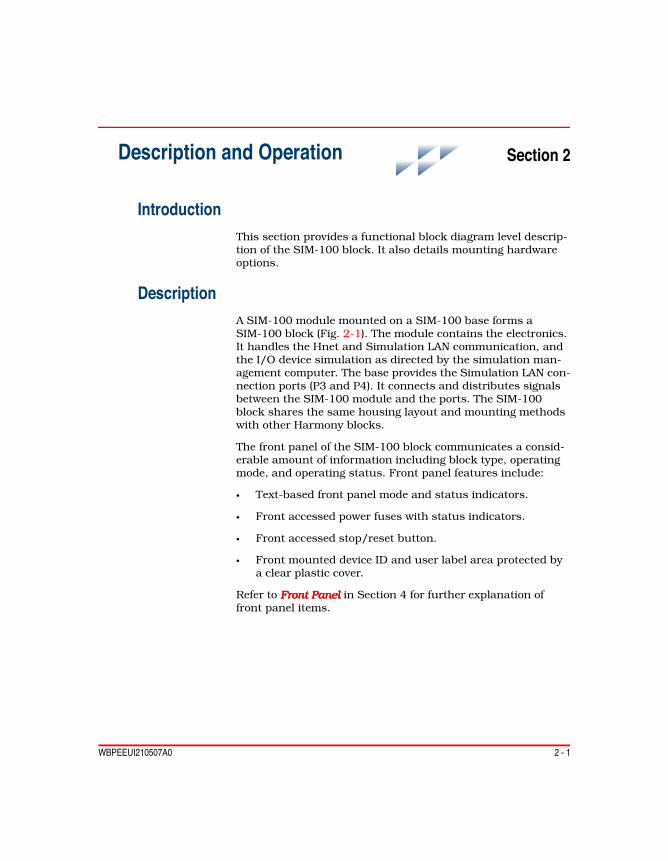
WBPEEUI210507A0 2 - 1
Section 2Description and Operation
IntroductionThis section provides a functional block diagram level descrip-tion of the SIM-100 block. It also details mounting hardware options.
DescriptionA SIM-100 module mounted on a SIM-100 base forms a SIM-100 block (Fig. 2-1). The module contains the electronics. It handles the Hnet and Simulation LAN communication, and the I/O device simulation as directed by the simulation man-agement computer. The base provides the Simulation LAN con-nection ports (P3 and P4). It connects and distributes signals between the SIM-100 module and the ports. The SIM-100 block shares the same housing layout and mounting methods with other Harmony blocks.
The front panel of the SIM-100 block communicates a consid-erable amount of information including block type, operating mode, and operating status. Front panel features include:
• Text-based front panel mode and status indicators.
• Front accessed power fuses with status indicators.
• Front accessed stop/reset button.
• Front mounted device ID and user label area protected by a clear plastic cover.
Refer to Front PanelFront PanelFront PanelFront Panel in Section 4 for further explanation of front panel items.

2 - 2 WBPEEUI210507A0
Description
ModuleThe SIM-100 module (Fig. 2-1) contains the processing cir-cuitry. Power conversion functions are also included. Front panel LEDs show power and operating status.
The block packaging gives access to the processor board for configuration by removing the side of the module (Fig. 2-2). The SIM-100 module can be removed and installed while sys-tem power is applied. A retractable handle facilitates the installation and removal of the module.
Figure 2-1. SIM-100 Block
S IM -100 MODULE
T03759A
S IM -100 BLOCK
SIM -100 BASE
WARNINGA SIM-100 module should not be inserted or removed withpower applied when located in a class I, division 2 hazardouslocation unless the area is known to be nonhazardous.

Description
WBPEEUI210507A0 2 - 3
The SIM-100 module mounts on a SIM-100 base. Mounting the module on the base makes the connections to Hnet and power. The Hnet and power connectors are actually a part of the mounting column and protrude through the base; refer to Block Mounting ColumnBlock Mounting ColumnBlock Mounting ColumnBlock Mounting Column in this section. A captive mounting screw on the module secures it in place.
Figure 2-3 is a functional block diagram of the SIM-100 mod-ule.
Central Processing UnitThe central processing unit (CPU) is an integrated communica-tions controller (ICC) that contains a 32-bit microprocessor running at 25 megahertz and its supporting circuitry. The ICC has built-in timers and control logic along with an integrated Ethernet coprocessor and serial channel interface.
Figure 2-2. Configuration Switch and Jumper Access
T03745A
PROCESSORBOARD
ACCESSCOVER

2 - 4 WBPEEUI210507A0
Description
Ethernet The integrated Ethernet coprocessor is used for SimulationLAN interface. The block supports several different Ethernetconnection methods dependent on the physical transmissionmedium:
• 10Base2 (thin coaxial) - transceiver (MSC-SIMBNC) and BNC terminated thin coaxial cable.
• 10Base5 (thick coaxial) - transceiver (tap) and AUI cable.
• 10BaseT (category 5, unshielded twisted-pair) - RJ-45 ter-minated twisted-pair cable. The SIM-100 module has a built-in 10BaseT transceiver.
• 10BaseFL (fiber optic) - transceiver and ST or SMA termi-nated fiber optic cable.
The Ethernet ports are located on the base: RJ-45 twisted-pair port (P4) and 15-pin, D-type AUI port (P3).
RS-232-C An integrated universal asynchronous receiver/transmitter(UART) circuit is used for the RS-232-C interface. TheRS-232-C port is a nine-pin, D-type connector (P7) locatedbehind the right-side access cover and is mainly used for firm-ware downloading and diagnostics. Refer to Appendix B forfirmware upgrade procedures.
Figure 2-3. Functional Block Diagram
T03757A
DATA BUS
MACHINEFAULTT IMER
A AB B
+24 VDC PLP
+5 VDC
+12 VDC AUIPORT(P3)
HNET
HNETINTERFACE
BLOCKPOWER
CPU STOP /RESET
SPEC IALOPERATIONSSW ITCH (SW 5)
IP ADDRESSSW ITCHES
(SW 1 TO SW 4)MEMORY STATUSLEDS
LEDDR IVERS
RS -232-CD IAGNOSTICPORT (P7)
ETHERNETAU I PORT
(P3)
ETHERNETRJ-45 PORT
(P4)
ETHERNETTRANSCE IVER

Description
WBPEEUI210507A0 2 - 5
MemoryThe module utilizes two types of memory: static-RAM (SRAM) memory and flash-ROM memory.
NOTE: The electronic ID (i.e., device ID) of the block is stored in ROM memory.
The SRAM memory for microprocessor use is a 72-pin SIMM SRAM module mounted on the processor board. This memory provides temporary storage to perform calculations and data manipulation. The Hnet interface also uses a shared SRAM memory to store received messages and messages to be trans-mitted.
The flash-ROM memory stores the operating firmware (i.e., boot and application programs). This type of memory provides the ability to download updated firmware without having to physically replace discrete components. Refer to Appendix B for firmware download procedures.
Hnet InterfaceHnet is the redundant, serial communication protocol over which the SIM-100 block communicates with the Harmony controller. Figure 2-4 details the Hnet interface section of the module circuitry. The Hnet interface encodes and transmits Hnet messages, receives and decodes Hnet messages, and monitors Hnet status.
The Hnet control portion of the interface is a custom, applica-tion-specific integrated circuit (ASIC). This circuit manages the serial communication protocol between the SIM-100 block and the controller. It also performs data integrity checks. The inter-face checks for the following message errors: data
Figure 2-4. Hnet Interface
TRANSCEIVERA
TRANSCEIVERB
HNETCONTROL
RELAYA
RELAYB
HNET A
HNET B
T00561B
DATA ANDCONTROL

2 - 6 WBPEEUI210507A0
Description
transmission error using cyclic redundancy check (CRC) method, maximum message reply time expired, and reply mes-sage overrun.
The Hnet control section also provides a means for the CPU to interrogate the Hnet to determine its condition. If a bus failure or stall is detected on either of the Hnet channels, the channel will be shut down locally until the problem is corrected.
The signal relays (A and B) allow the SIM-100 module to iso-late itself from Hnet in the event of a component failure or to perform diagnostics. This important feature assures that a fault in one block cannot affect the communications of other blocks. The Hnet interface circuitry includes the logic that controls the relays.
Refer to the Harmony Communications Network (Hnet)Harmony Communications Network (Hnet)Harmony Communications Network (Hnet)Harmony Communications Network (Hnet) instruction for a complete description of Hnet and for Hnet specifications.
Machine Fault TimerThe machine fault timer (MFT) is a built-in security feature. The timer is a one-shot timer that must be periodically reset by the CPU to prevent it from timing out. If an error condition exists that causes the module to fail or operate incorrectly, the timer will not be reset and will cause a time out condition. A time out condition triggers a reset signal to shut down the module.
The module performs a series of online diagnostics to verify circuit integrity. A detected hardware failure may cause a time out condition. If the cause of the problem is not a hardware failure the module and timer can be reset by the manual reset switch accessed through the block front panel. A hardware failure will most likely require a module replacement.
Block PowerThe SIM-100 module provides onboard regulation of its operat-ing voltages. The module accepts redundant 24 VDC inputs which it filters, auctioneers, and regulates. Each 24 VDC input is fused and monitored. Figure 2-5 details the block power sec-tion.
Logic Power Redundant 24 VDC block logic power (BLP) is bussed through the mounting column to the module. The redundant BLP

Description
WBPEEUI210507A0 2 - 7
power is auctioneered through summing diodes into a single 24 VDC. Onboard DC-to-DC converters develop the +5 VDC operating voltage from the integrated 24 VDC. Also, the single 24 VDC is converted to +12 VDC used to power the AUI port. To avoid damage from short circuits, the +12 VDC is protected by a resettable fuse.
The module tests itself for a +5 VDC out-of-range condition. When this voltage is outside its normal operating range, a hardware fault (i.e., power on reset) will occur and the block operation will halt.
Power Monitor The power monitor circuits test and report the status of the redundant 24 VDC BLP inputs. The inputs are only tested for their presence or absence. The circuits do not test the inputs for voltage range. The SIM-100 module will generate a SOA alarm if the fuse for any of these inputs is bad or if the input voltage is absent.
Refer to the Block Power and Mounting HardwareBlock Power and Mounting HardwareBlock Power and Mounting HardwareBlock Power and Mounting Hardware instruction for a complete explanation of BLP power and the SOA alarm signal for power status monitoring.
LED Drivers and Status LEDsThe LED drivers control the front panel status indicators as directed by the CPU. The indicators show module operating status, communication status, and power status.
Figure 2-5. Block Power
POWERAUCTIONEER
POWERFILTER
POWERMONITOR
5 VDCPOWER
REGULATOR
12 VDCPOWER
REGULATOR
+24 VDC +24 VDC
SOAALARM
POWERSTATUS
BLOCKPOWER
AU IPORT (P3)
+5 VDC
+12 VDC
BLP B
BLP A
+24 VDCFROMMOUNTINGCOLUMN
T03758A

2 - 8 WBPEEUI210507A0
Description
SwitchesThe special operations switch SW5 is used to enable normal operation and to enable firmware download. Switches SW1 through SW4 set the IP address for Simulation LAN communication.
Stop/ResetControl logic determines the stop/reset pushbutton operation. The pushbutton is used to halt the module operation and to reset the module. It is accessible through a small hole in the front panel. Pressing the pushbutton once causes the module to perform an orderly shutdown. Pressing the pushbutton a second time resets the module.
BaseThe SIM-100 module mounts on the SIM-100 base. Figure 2-6 shows the base.
Figure 2-6. SIM-100 Base
T03755A

Mounting Hardware
WBPEEUI210507A0 2 - 9
The base attaches directly to a block mounting column; refer to Block Mounting ColumnBlock Mounting ColumnBlock Mounting ColumnBlock Mounting Column in this section. Alignment posts help locate the base on the mounting column. The assembly is physically mounted using two captive screws. Tabs on the base insert into slots in the mounting column to help further secure the base in place. The Simulation LAN connects to the base and the Ethernet signals are routed internally to SIM-100 module connectors. Simulation LAN connections remain undisturbed if the module is removed or replaced.
The base has a front panel door to conceal and protect the connectors. A label is affixed to the inside of the door to explain and identify the Ethernet ports and the jumper set-tings.
Hardware KeyingThe SIM-100 module as with other Harmony blocks requires its own type of base. Hardware keying using posts on the base and holes in the back of the module prevents an accidental mismatch of module and base. The block type and model num-ber shown on the front panel of the module and the base are the same to easily identify that they are compatible.
Mounting HardwareBlock mounting hardware inside the enclosure creates the framework that both secures Harmony blocks in place and creates the system backplane to route power, communication signals, and chassis ground. Figure 2-7 shows some of the block mounting hardware available. Specifically it shows MSC-CMB column mounting bars and MCL-111 block mount-ing columns. Refer to the Block Power and MountingBlock Power and MountingBlock Power and MountingBlock Power and Mounting instruc-tion for a description of additional mounting hardware that can be used with the SIM-100 block.
Column Mounting BarThe column mounting bars (Fig. 2-7) are for attaching block mounting columns. These supports attach to the vertical channels that run along the sides of the enclosure.

2 - 10 WBPEEUI210507A0
Mounting Hardware
Block Mounting ColumnThe MCL-111 block mounting column is a single block height, stackable column (Figs. 2-7 and 2-8) that is used for attaching and connecting a SIM-100 block. The column attaches to the mounting bars; the SIM-100 block attaches directly to the column.
Figure 2-7. Block Mounting Hardware
T03756A
ENCLOSURES IDE RA IL
COLUMNMOUNTINGBAR
BLOCKMOUNTINGCOLUMN

Mounting Hardware
WBPEEUI210507A0 2 - 11
Signal DistributionThe MCL-111 mounting column distributes both power and Hnet communication signal lines. For the SIM-100 block it routes redundant Hnet, redundant 24 VDC BLP power, system common, and a status output alarm (SOA) signal.
NOTE: The controller supports one SIM-100 block; each controller requires its own SIM-100 block.
The MCL-111 column provides two Hnet connection points. When operating with simulated I/O only, the controller con-nects to the top Hnet connector and a Hnet terminator attaches at the bottom Hnet connector. When using real I/O from Harmony I/O blocks, multiple columns are connected together within an enclosure to form a single Hnet segment.
Figure 2-8. MCL-111 Block Mounting Column (Hnet Cover Plate Removed)
POWER IN
POWER OUT
BLOCK POWERAND HNET
HNET
T03763A

2 - 12 WBPEEUI210507A0
Mounting Hardware
Typically, Hnet is cabled from the controller to the top connec-tor of the MCL-111 column, then it cable connects from the bottom connector to a column with I/O blocks. Columns can-not be connected together, however, in a way that would put more than one SIM-100 block on the same Hnet.
For the BRC-100 controller, Hnet cable connects from the pro-cessor bus adapter (BRC-PBA). This assembly is the hardware adapter used to connect Hnet and other communications to the BRC-100 controller.

WBPEEUI210507A0 3 - 1
Section 3Installation
IntroductionThis section describes SIM-100 block installation and connec-tion. This instruction discusses only SIM-100 block installa-tion requirements. It does not provide any simulation system planning information and assumes all components have already been purchased and are ready to be installed.
Special HandlingObserve these steps when handling electronic circuitry:
1. Use Static Shielding Bag.Use Static Shielding Bag.Use Static Shielding Bag.Use Static Shielding Bag. Keep an assembly in its static shielding bag until ready to install it in the system. Save the bag for future use.
2. Ground Bags before Opening.Ground Bags before Opening.Ground Bags before Opening.Ground Bags before Opening. Before opening a bag con-taining an assembly with static sensitive devices, touch it to the equipment housing or ground to equalize charges.
3. Avoid Touching CircuitryAvoid Touching CircuitryAvoid Touching CircuitryAvoid Touching Circuitry. Handle assemblies by the plas-tic outer packaging; avoid touching the circuitry.
4. Ground Test EquipmentGround Test EquipmentGround Test EquipmentGround Test Equipment.
5. Use an Antistatic Field Service VacuumUse an Antistatic Field Service VacuumUse an Antistatic Field Service VacuumUse an Antistatic Field Service Vacuum. Remove dust from assemblies if necessary.
6. Use a Grounded Wrist Strap.p.p.p. Use the ABB Automation field static kit (part number 1948385A1 - consisting of two wrist straps, ground cord assembly, alligator clip, and static dissipative work surface) when working with modules. The kit grounds a technician and the static dissipative work surface to the same ground point to prevent damage to the circuitry by electrostatic discharge. Connect the wrist strap to the appro-priate grounding plug on the power supply or to an unpainted portion of the enclosure with the alligator clip. The wrist strap must be effectively connected to the earth grounding electrode system through the AC safety ground.

3 - 2 WBPEEUI210507A0
Unpacking and Inspection
7. Do Not Use Lead Pencils to Set SwitchesDo Not Use Lead Pencils to Set SwitchesDo Not Use Lead Pencils to Set SwitchesDo Not Use Lead Pencils to Set Switches. To avoid con-tamination of switch contacts that can result in unnecessary circuit board malfunction, do not use a lead pencil to set a switch.
Unpacking and Inspection1. Examine the hardware immediately to verify that it has not been damaged in transit.
2. Notify the nearest ABB sales office of any damage.
3. File a claim for any damage with the transportation com-pany that handled the shipment.
4. Use the original packing material and container to store the hardware.
5. Store the hardware in an environment of good air quality, free from temperature and moisture extremes and corrosives.
Installation and Connection Sequence
NOTE: Always follow the instructions given in Special Handling in this section when handling the SIM-100 module.
Figure 3-1 is the installation and connection flowchart. This flowchart applies whether installing a SIM-100 block in a new system or in an existing system.
In the flowchart, each flowchart block represents a single task. The PR code in the flowchart block identifies the procedure section that describes the steps to complete the indicated task. For example, turn to section PR4 to read about SIM-100 mod-ule installation. Some steps are self-explanatory and have no related procedure section. Complete all steps given in a proce-dure section before continuing to the next flowchart block. The procedure sections are located towards the back of the instruction.
WARNINGA SIM-100 module should not be inserted or removed withpower applied when located in a class I, division 2 hazardouslocation unless the area is known to be nonhazardous.

Installation and Connection Sequence
WBPEEUI210507A0 3 - 3
Figure 3-1. Installation and Connection Flowchart
INSTALL COLUMNMOUNTING
BARSPR1
INSTALLSIM -100 BASE
SEPARATES IM -100 MODULEFROM ITS BASE
PR3
INSTALL BLOCKMOUNTINGCOLUMN
PR2
SETUPSIM -100 BLOCK
PR5
CONNECTBLOCK POWER
PR6
INSTALLS IM -100 MODULE
PR4
CONNECTHNET
PR7
CONNECTSIMULATION
LANPR8
START
TR3742A
DONE

WBPEEUI210507A0

WBPEEUI210507A0 4 - 1
Section 4Operating Procedures
IntroductionThis section provides operating information for the SIM-100 block. It describes front and rear panel items, and describes startup and stop/reset.
Front PanelAll Harmony blocks share similar front and rear panel layouts. Figure 4-1 shows the SIM-100 block front panel. The front panel communicates a considerable amount of information. At a glance the following information can easily be discerned:
• Block type and model.• Operating mode.• Operating status.• Power status.• Communication status.
A block type identifier enables quickly and easily identifying general block type. A model number distinguishes between the different block versions within a given block category.
Operating Mode - Normal and FaultThe NORMAL and FAULT indicate block operating mode. Table 4-1 summarizes the indications. Refer to Table 5-1 for corrective actions for any problem indications.
Block StatusThe eight status indicators show normal and error status codes. The status appears as an eight-bit binary status code, which can be deciphered using look-up tables provided. LED eight is the most significant bit. Refer to Table 4-2 for normal operating mode status codes. Refer to Table 5-3 for error sta-tus codes.

4 - 2 WBPEEUI210507A0
Front Panel
Figure 4-1. SIM-100 Block Front Panel
T03737A
STOP/RESET
TYPE
MODEL
ACCESSDOOR
FUSEHOLDER
RETRACTABLEHANDLE
LABELS
1ST FLOOR CABINET
SIMULATOR
12345678
A
B
FAULT NORMAL
STATUS
BLOCKPOWER
CH1CH2
TXRX
COLL
TPAU I
L INKPOL
OK
HNET
ETHERNETACT IV ITY
TP STATUS
AU I POWER
1.6 A
1.6 A
100100SIM SIM
Table 4-1. Operating Mode - Normal and Fault LEDs
Indicator State DescriptionNormal On Operational and online.
Flashing Operational and offline. Connected to Simulation LAN but communicationwith controller not established or lost.
Off Fault condition exists (with FAULT indicator on).No power. If this condition exists, no front panel LEDs will be on.

Front Panel
WBPEEUI210507A0 4 - 3
Block PowerThe block power indicators (A and B) give a good or bad status indication for the redundant 24 VDC block logic power inputs to the block. The status indicator on indicates a good power input. The inputs are tested after their front panel fuses, which means a bad input indication could be a blown fuse, bad connection, or it could be a problem with the actual power source. A problem with the power source, however, will cause a bad status indication on other blocks.
Communication StatusTable 4-3 summarizes communication status indications. These indications relate to Hnet and Simulation LAN commu-nication.
ID LabelsThe front panel contains two labels at the bottom of the SIM-100 module: inner and outer labels. The labels are located in a small recess covered by a removable clear plastic lens.
Fault On CPU halted due to hardware or other fatal error; refer to Table 5-3.Machine fault timer expired. Refer to Machine Fault Timer in Section 2.Stop/reset button pressed.
Off No fault condition.No power. If this condition exists, no front panel LEDs will be on.
Table 4-1. Operating Mode - Normal and Fault LEDs (continued)
Indicator State Description
Table 4-2. Normal Operating Mode Status Codes
Status LEDs Condition1 2 3 4 5 6 7 8 Initial value at reset or powerup.x x x x x x x 8 1. Startup; refer to Startup in this section.
2. Firmware download; refer to Table B-1.x x x x x x 7 – Run-time error; refer to Table 5-3.– – – – – – 7 8 Normal operation.1 – – – – 6 7 – Normal stop; stop button pressed.NOTES: – = LED off; x = varies.

4 - 4 WBPEEUI210507A0
Front Panel
Inner Label The inner label is permanently adhered to the block. It gives device identification information which includes the device ID number and a device description. The device ID is both a serial number and the unique electronic ID assigned at the factory. The following is an example inner label:
Table 4-3. Communication Status LEDs
LED DescriptionHnet CH1 Indicates the status of the Hnet channel A and channel B relays:
On = closed (good).Off = open (bad).
Refer to Hnet Interface in Section 2 for an explanation of the Hnetchannel relays.
CH2
Ethernetactivity
TX Indicates when any Ethernet packets are being sent on the SimulationLAN. Randomly flashes when the SIM-100 block is transmitting; offwhen the block is idle.
RX Indicates when any Ethernet packet is observed on the Simulation LANeven if addressed to another node. Randomly flashes when there istraffic on the Simulation LAN; off when the network is idle.
COLL Indicates when an Ethernet packet being sent collides with anotherpacket on the Simulation LAN. Randomly flashes while the SIM-100block is transmitting but at a much slower rate than TX and RX.
Alternately driven on and off during a jabber condition. Jabber occurswhen some faulty network transmitter is exceeding the maximum allow-able frame duration of 20 to 150 msec.
TP Indicates that 10BaseT Simulation LAN is connected at the RJ-45 port(P4).
AUI Indicates that 10Base2, 10Base5, or 10BaseFL Simulation LAN is con-nected at the AUI port (P3).
Twisted-pair(TP) status
LINK Indicates that 10BaseT Simulation LAN cabling is OK. The SIM-100block senses the hub or switch at the other end of the cable.
POLARITY Indicates a polarity error in the 10BaseT Simulation LAN cable. TheSIM-100 block will still communicate correctly. Logic circuitry in theblock can correct the polarity of the incoming network signal.
AUI power OK Indicates the status of the AUI port 12 VDC power. A problem can becaused, for example, by a shorted cable or a damaged transceiverdrawing excessive current.
Device ID: 123456789ABC
Simulator

Module Rear Panel
WBPEEUI210507A0 4 - 5
Outer Label The outer label, which is for customer use, provides an area for customer identification of the particular block. It also con-tains a brief block application description. The following is an example outer label:
Module Rear PanelFigure 4-2 shows the rear panel of the SIM-100 module. The switch and connectors are recessed to allow resting the assem-bly face up on a table. Refer to Table PR5-2 for switch SW5 settings.
OperationThis section details the SIM-100 block startup sequence and describes stop/reset button operation.
StartupA startup sequence occurs after a power on or manual reset of the block. Plugging the SIM-100 module into its base connects power and begins the start up. The block first performs a series of startup diagnostics. Refer to DiagnosticsDiagnosticsDiagnosticsDiagnostics in Section 5 for a description. During this phase the status LEDs show var-ious codes while NORMAL remains off. If the diagnostics checks pass LEDs one through six turn off and LEDs seven
1ST FLOOR CABINET
Simulator
Figure 4-2. SIM-100 Module Rear Panel
SW5: SPECIAL OPERATIONS P4: ETHERNET P1 : POWER P5 : COMMUNICATION
POWER CONSUMPTION
P-HB-SIM-10010000
ATTENTIONELECTRO STATIC
SENSITIVEDEVICES
(See Instructions)
+24VDC,500mA
E S D8 7 6 5 4 3 2 1
T03738A
CLOSED
OPEN

4 - 6 WBPEEUI210507A0
Operation
and eight turn on to indicate normal operation. Table 4-4 shows the startup sequence.
Stop/ResetThe stop/reset button (Fig. 4-1) is used to interrupt execution and to initiate a hardware reset. The button is accessed through the small opening on the front panel. Some type of thin rod, preferably nonmetallic, is required to press the button.
First PressStop
Press the button once to halt operation. The electronics con-duct an orderly shutdown after stop is initiated:
1. Deactivate all communication links.
2. Illuminate FAULT and set the status LEDs.
Second PressReset
Press the button a second time to initiate a hardware reset. A hardware reset is required to recover from a module time-out or a manual stop (single press). After the hardware reset com-pletes, the block then begins its startup sequence.
NOTE: If the module has already stopped due to an error (i.e., FAULT lit), a sin-gle press resets the module.
Table 4-4. LEDs - Startup Sequence
Normal Fault Status LEDs DescriptionOff Off 1 2 3 4 5 6 7 8 Initial value at reset or powerup.Off Off x x x x x x x 8 Countdown sequence during star-
tup diagnostic tests.Off Off – – – – – – – – Startup diagnostics complete
(appears for a fraction of a second)On Off – – – – – – 7 8 Normal operation.
NOTES: – = LED off; x = varies.1. If the SIM-100 module stops before reaching the normal operation pattern, reset the module. Ifthe problem persists, replace the module.

WBPEEUI210507A0 5 - 1
Section 5Troubleshooting
IntroductionThis section provides troubleshooting information necessary to isolate SIM-100 block errors. It is not meant to be all inclusive. If a problem exists that cannot be corrected using the informa-tion provided in this instruction, contact a local ABB service office for assistance.
Troubleshooting ProceduresTroubleshooting of the SIM-100 block is performed mainly by observing the block front panel LEDs. The operation of the front panel LEDs is described in Front Panel in Section 4.
The SIM-100 module runs diagnostics checks during startup and normal operation to test for hardware problems. Refer to DiagnosticsDiagnosticsDiagnosticsDiagnostics in this section for a description. If the diagnostics detect a problem, reset the module. If the error recurs, replace the SIM-100 module.
NOTE: All tables in this section give corrective actions for single block indica-tions. If the same indication is given for more than one block, consider a power system or communications system problem.
Operating Mode - Normal and Fault LEDsTable 5-1 summarizes the normal and fault LED indications and gives corrective actions.
Block Power LEDsTable 5-2 summarizes the block power LED indications and gives corrective actions.
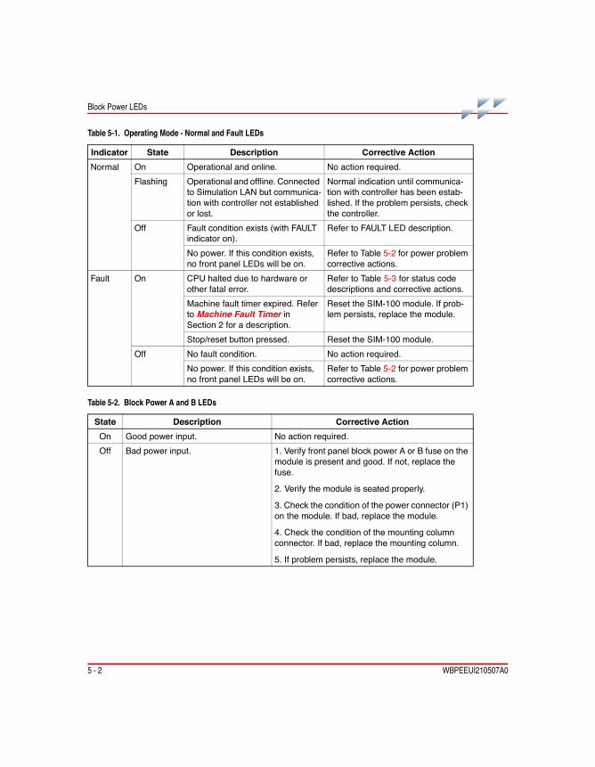
5 - 2 WBPEEUI210507A0
Block Power LEDs
Table 5-1. Operating Mode - Normal and Fault LEDs
Indicator State Description Corrective ActionNormal On Operational and online. No action required.
Flashing Operational and offline. Connectedto Simulation LAN but communica-tion with controller not establishedor lost.
Normal indication until communica-tion with controller has been estab-lished. If the problem persists, checkthe controller.
Off Fault condition exists (with FAULTindicator on).
Refer to FAULT LED description.
No power. If this condition exists,no front panel LEDs will be on.
Refer to Table 5-2 for power problemcorrective actions.
Fault On CPU halted due to hardware orother fatal error.
Refer to Table 5-3 for status codedescriptions and corrective actions.
Machine fault timer expired. Referto Machine Fault Timer inSection 2 for a description.
Reset the SIM-100 module. If prob-lem persists, replace the module.
Stop/reset button pressed. Reset the SIM-100 module.Off No fault condition. No action required.
No power. If this condition exists,no front panel LEDs will be on.
Refer to Table 5-2 for power problemcorrective actions.
Table 5-2. Block Power A and B LEDs
State Description Corrective ActionOn Good power input. No action required.Off Bad power input. 1. Verify front panel block power A or B fuse on the
module is present and good. If not, replace thefuse.
2. Verify the module is seated properly.
3. Check the condition of the power connector (P1)on the module. If bad, replace the module.
4. Check the condition of the mounting columnconnector. If bad, replace the mounting column.
5. If problem persists, replace the module.

Block Status LEDs
WBPEEUI210507A0 5 - 3
Block Status LEDsThe eight status indicators show both normal and error status codes. The status codes appear in binary format. LED eight is the most significant bit. Refer to Table 5-3 to decipher status codes.
Table 5-3. Status Codes
Code LED On Condition Corrective Action69 0x45 1 – 3 – – – 7 – Error during firmware upgrade 1. Reset SIM-100 module, then
try upgrade again.
2. Check SW5 for proper firm-ware upgrade setting. Refer toTable PR5-2.
3. If problem persists, replacethe SIM-100 module.
71 0x47 1 2 3 – – – 7 – Bus error during SDMA 1. Reset SIM-100 module.
2. If problem persists, replacethe SIM-100 module.
72 0x48 – – – 4 – – 7 – Write protection error73 0x49 1 – – 4 – – 7 – Run-time error on diagnostic
port74 0x4A – 2 – 4 – – 7 – Flash-ROM checksumming
failed80 0x50 – – – – 5 – 7 – Bus error81 0x51 1 – – – 5 – 7 – Address error82 0x52 – 2 – – 5 – 7 – Illegal instruction83 0x53 1 2 – – 5 – 7 – Division by zero84 0x54 – – 3 – 5 – 7 – Check instruction85 0x55 1 – 3 – 5 – 7 – Trap V86 0x56 – 2 3 – 5 – 7 – Privilege violation87 0x57 1 2 3 – 5 – 7 – Trace88 0x58 – – – 4 5 – 7 – Emulator 1010 exception89 0x59 1 – – 4 5 – 7 – Emulator 1111 exception90 0x5A – 2 – 4 5 – 7 – Unassigned exception91 0x5B 1 2 – 4 5 – 7 – Trap X92 0x5C – – 3 4 5 – 7 – Nonmaskable exception93 0x5D 1 – 3 4 5 – 7 – Spurious exception94 0x5E – 2 3 4 5 – 7 – Uninitialized exception

5 - 4 WBPEEUI210507A0
Block Status LEDs
95 0x5F 1 2 3 4 5 – 7 – Uninitialized exception fromcommunication controller
1. Reset SIM-100 module.
2. If problem persists, replacethe SIM-100 module.96 0x60 – – – – – 6 7 – Communication controller error
97 0x61 1 – – – – 6 7 – STOP interrupt1
98 62 – 2 – – – 6 7 – DSP interrupt1
99 0x63 1 2 – – – 6 7 – SOA interrupt1
100 0x64 – – 3 – – 6 7 – HNET ASIC interrupt1
101 0x65 1 – 3 – – 6 7 – Generic level 5 interrupt1
102 0x66 – 2 3 – – 6 7 – Generic Level 6 interrupt1
103 0x67 1 2 3 – – 6 7 – Generic level 7 interrupt1
106 0x6A – 2 – 4 – 6 7 – Spurious interrupt from Hnetchip
107 0x6B 1 2 – 4 – 6 7 – Error while testing Hnet sharedRAM
108 0x6C – – 3 4 – 6 7 – CHT TX buffer full109 0x6D 1 – 3 4 – 6 7 – CHT RX buffer full110 0x6E – 2 3 4 – 6 7 – LAN RX buffer full111 0x6F 1 2 3 4 – 6 7 – LAN TX buffer full112 0x70 – – – – 5 6 7 – Duplicate device label detected113 0x71 1 – – – 5 6 7 – Hnet chip failure114 0x72 – 2 – – 5 6 7 – Duplicate source address115 0x73 1 2 – – 5 6 7 – ID-ROM access error128 0x80 – – – – – – – 8 Firmware download complete
(downloaded file terminates withCTRL-Z)
No action required.
136 0x88 – – – 4 – – – 8 Firmware download beginning137 0x89 1 – – 4 – – – 8 Flash-ROM erase in progress
during firmware download138 0x8A – 2 – 4 – – – 8 Firmware download complete
(downloaded file does not termi-nate with CTRL-Z)
139 0x8B – – 3 4 – – – 8
— 0x8? – x x 4 – – – 8 Receiving firmware code192 0xC0 – – – – – – 7 8 Normal operationNOTES: – = off; x = toggle.1. External interrupt occurred before being configured by firmware.
Table 5-3. Status Codes (continued)
Code LED On Condition Corrective Action

Diagnostics
WBPEEUI210507A0 5 - 5
DiagnosticsThe SIM-100 module firmware contains various diagnostic routines used to verify proper operation of components and circuitry:
• CPU test.• SRAM memory test.• Flash-ROM memory test.• Internal device tests (i.e., Ethernet, UART, timers, etc.).• ID-ROM test.• Hnet tests.
These diagnostics are automatically run during startup. If any of these tests detect a problem, the SIM-100 module will halt. If this occurs, reset the module. If the problem persists, replace the module. Refer to Startup in Section 4 for addi-tional startup information.
SIM-100 Module Connectors (P1, P4, P5, P7)The SIM-100 module has four connection points for external signals and power: P1 power, P4 Ethernet, P5 communication, and P7 RS-232-C port. Tables 5-4 through 5-7 list the pin assignments for these connectors.
Table 5-4. P1 Power Pins
Pin ConnectionA 1 BLP A (+)
2 BLP B (+)3 NC
B 1 BLC A (–)2 BLC B (–)3 NC
NOTE: NC = not connected.
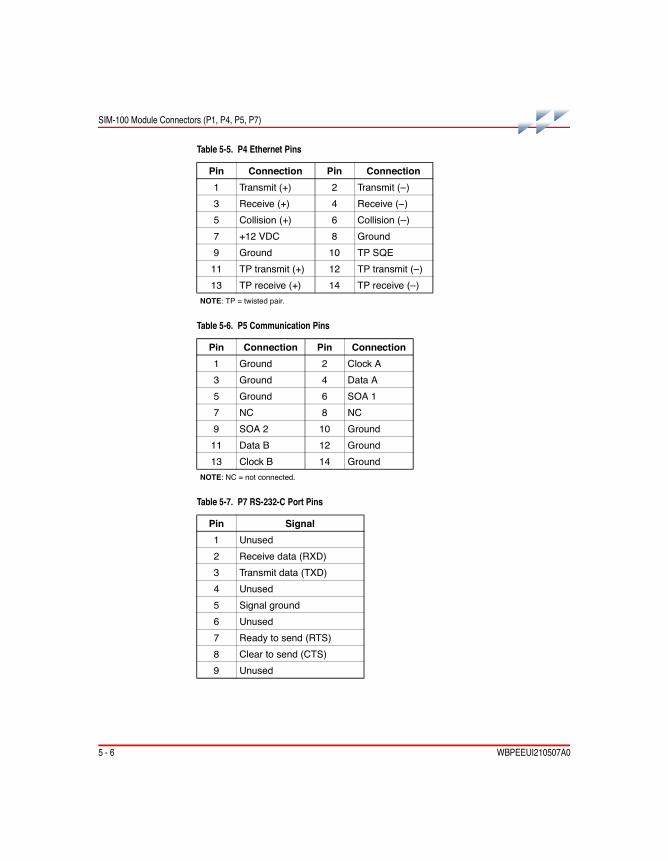
5 - 6 WBPEEUI210507A0
SIM-100 Module Connectors (P1, P4, P5, P7)
Table 5-5. P4 Ethernet Pins
Pin Connection Pin Connection1 Transmit (+) 2 Transmit (–)3 Receive (+) 4 Receive (–)5 Collision (+) 6 Collision (–)7 +12 VDC 8 Ground9 Ground 10 TP SQE11 TP transmit (+) 12 TP transmit (–)13 TP receive (+) 14 TP receive (–)
NOTE: TP = twisted pair.
Table 5-6. P5 Communication Pins
Pin Connection Pin Connection1 Ground 2 Clock A3 Ground 4 Data A5 Ground 6 SOA 17 NC 8 NC9 SOA 2 10 Ground11 Data B 12 Ground13 Clock B 14 Ground
NOTE: NC = not connected.
Table 5-7. P7 RS-232-C Port Pins
Pin Signal1 Unused2 Receive data (RXD)3 Transmit data (TXD)4 Unused5 Signal ground6 Unused7 Ready to send (RTS)8 Clear to send (CTS)9 Unused

WBPEEUI210507A0 6 - 1
Section 6Maintenance
IntroductionThe reliability of any stand-alone product or control system is affected by the maintenance of the equipment. ABB Automa-tion recommends that all equipment users practice a preven-tive maintenance program that will keep the equipment operating at an optimum level.
This section presents procedures that can be performed on-site. These preventive maintenance procedures should be used as guidelines to assist in establishing good preventive maintenance practices. Select the minimum steps required to meet the cleaning needs of your system.
Personnel responsible for maintenance should be familiar with the Harmony components of the Symphony system, have expe-rience working with process control systems, and know what precautions to take when working on live AC systems.
Preventive Maintenance ScheduleTable 6-1 is the preventive maintenance schedule for the SIM-100 block. The table lists the preventive maintenance tasks in groups according to their specified maintenance inter-val. Some tasks in Table 6-1 are intuitive or self explanatory. Instructions for tasks that require further explanation are cov-ered in the indicated procedure section.
NOTE: The preventive maintenance schedule is for general purposes only. Your application may require special attention.

6 - 2 WBPEEUI210507A0
Preventive Maintenance Schedule
Table 6-1. Preventive Maintenance Schedule
Task Procedure FrequencyGeneral cleaning. Use a lint-free cloth and mild, all-purpose, nonflam-mable, commercial spray cleaner to remove dirt, fingerprints, andgrease from the equipment (e.g., LCD screen, keypad, housing assem-bly). Spray the cleaner on the cloth and not directly on the equipment.
N/A As required
Check cabinet air filters. Clean or replace them as necessary. Check theair filter more frequently in excessively dirty environments.
N/A 3 months
Check block faceplate and housing and the cooling fan assembly fordust. Clean as necessary using an antistatic vacuum. Insure air ventsare free of dust and lint.
N/A
Check all signal, power, ground, and cable connections associated withthe block; verify they are secure.
PR9
Complete all tasks in this table. N/A Shutdown

WBPEEUI210507A0 7 - 1
Section 7Repair and Replacement
IntroductionThis section explains repair and replacement procedures for the SIM-100 block.
RepairRepair is limited to assembly replacement. If a block compo-nent such as the SIM-100 module or SIM-100 base fails, remove and replace it with another. Do notnotnotnot attempt to replace discrete components in any system assembly.
Replacement
NOTE: Always follow the instructions given in Special Handling in Section 3 when handling the SIM-100 module.
The replacement procedures for most parts and assemblies are intuitive. Figure 7-1 is the replacement flowchart, which con-tains replacement procedures for those parts and assemblies that need explanation.
In the flowchart, each flowchart block represents a single task. The PR code in the flowchart block identifies the procedure section that describes the steps to complete the indicated task. Some steps are self-explanatory and have no related procedure section. Complete all steps given in a procedure section before continuing to the next flowchart block. The procedure sections are located towards the back of the instruction.
WARNINGA SIM-100 module should not be inserted or removed withpower applied when located in a class I, division 2 hazardouslocation unless the area is known to be nonhazardous.

7 - 2 WBPEEUI210507A0
Replacement
Figure 7-1. Replacement Flowchart
SIM -100 MODULE SIM -100 BASE
PR10
REMOVEMODULE
D ISCONNECTSIMULATION LANTRANSCEIVEROR CABLE
REMOVEBASE
PR11
REMOVEMODULE
PR10
SET UP SW ITCHES,JUMPER , AND FUSESON REPLACEMENTSAME AS MODULEBEING REPLACED
INSTALLREPLACEMENT
MODULEPR4
START
TR3743A
SET UP JUMPERON REPLACEMENTSAME AS BASE
BEING REPLACED
INSTALLREPLACEMENT
BASEPR3
CONNECTS IMULAT ION LANTRANSCE IVEROR CABLE
INSTALLMODULE
PR4
DONE

WBPEEUI210507A0 8 - 1
Section 8Replacement and Spare Parts
IntroductionThis section provides installation, replacement, and spare part nomenclature and part numbers. Contact ABB for help deter-mining the quantity of spare parts to keep on hand for your particular system.
Block NomenclatureTable 8-1 lists the SIM-100 block nomenclature.
Cable NomenclatureTable 8-2 lists cable nomenclature. Refer to the Harmony Harmony Harmony Harmony Communications Network (Hnet) Communications Network (Hnet) Communications Network (Hnet) Communications Network (Hnet) instruction for Hnet cable nomenclature.
Table 8-1. Simulation Block Nomenclature1 2 3 4 5 6 7 8 9 10 11 12 13 14 15 16 17
P - H B - S I M - 1 0 0 _ _ _ _ _ Block Nomenclature
Module/Base Option0 C 1 _ _ Base1 0 0 _ _ Module
Reserved for Future Use0 0 Must be zeros
Table 8-2. Power Cable Nomenclature1 2 3 4 5 6 7 8 9 10 11 12 13 14 15 16 17
P - M K - H R M - P W R 6 0 0 0 _ Power Cable
Lengthx 1 to 8 for 1.0 to 8.0 m (3.3 to 26 ft)

8 - 2 WBPEEUI210507A0
Miscellaneous Nomenclature
Miscellaneous NomenclatureTable 8-4 lists related, miscellaneous parts and their part numbers.
Miscellaneous PartsTable 8-4 lists related, miscellaneous parts and their part numbers.
Table 8-3. Miscellaneous Nomenclature1 2 3 4 5 6 7 8 9 10 11 12 13 14 15 16
P - H A - M C L 1 1 1 0 0 0 0 0 Stackable Block Mounting Column
P - H A - M S C C M B 1 0 0 0 0 Column Mounting Bar
P - H A - M S C S I M B N C 0 0 10Base2 (Thin Coaxial) Transceiver
P - H A - M S C T E R 2 0 0 0 0 Hnet Terminator(accommodates redundant channels)
Table 8-4. Miscellaneous Parts
Number Part1949438A1601 1.6 A, 250 V, 5 x 20 mm, fast-acting, low break capacity200013A050T100 M5 × 10-mm, hex-head, thread-forming screw6642146A1 Plastic lensEL 2089 M6 Phillips-head screw (CAB-04/12)EL 2094 M6 captive nut (CAB-04/12)NIDHA16008 0.19-32 (no. 10) × 0.5 in., Phillips-head screw (CAB-01)NMPCC16002 0.19-32 (no. 10) cage nut (CAB-01)

WBPEEUI210507A0 A - 1
Appendix AHardware Drawings
IntroductionThis section provides drawings showing dimensions for the SIM-100 block, block mounting column, and column mounting bar.
SIM-100 BlockFigures A-1 and A-2 are the SIM-100 module and SIM-100 base.
Figure A-1. SIM-100 Module
T02058B
76.23 .00
1626.38
D IMENS IONSM ILLIMETERS
INCHES
266.010.47

A - 2 WBPEEUI210507A0
SIM-100 Block
Figure A-2. SIM-100 Base
T01105B
137.65.42
D IMENS IONSM ILLIMETERS
INCHES
169.26.66
267.110.51

Block Mounting Column
WBPEEUI210507A0 A - 3
Block Mounting ColumnFigure A-3 is the block mounting column.
Figure A-3. Block Mounting Column
160 .56.32
197.57.78
29.01 .14
T03733A
D IMENSIONSM ILL IMETERS
INCHES
266.710 .50

A - 4 WBPEEUI210507A0
Column Mounting Bar
Column Mounting BarFigure A-4 is the column mounting bar.
Figure A-4. Column Mounting Bar
495 .319.50 9 .5
0.38
12.50 .49
44.51 .75
T01381B
D IMENS IONS
INCHESMILLIMETERS

WBPEEUI210507A0 B - 1
Appendix BFirmware Upgrade
IntroductionThe SIM-100 block firmware resides in flash-ROM memory which provides the ability to upgrade firmware without having to physically replace discrete components. Currently, new firmware is loaded into the SIM-100 module through its diag-nostic port (P7). This requires the side cover of the module to be removed and the special operations switch (SW5) on the back of the module to be set to enable firmware upgrade. The SIM-100 diagnostic port uses simple null modem (i.e., cross-over), full duplex connection with no handshaking (Fig. B-1). Refer to Table 5-7 for P7 pin assignments.
ProcedureA download utility (simdwnld.exe) included with the Simula-tion LAN and API software is used to perform firmware down-loading. To download firmware:
1. Remove the SIM-100 module. Refer to procedure section PR10 if necessary.
2. Record the current special operations switch SW5 settings.
Figure B-1. RS-232-C Diagnostic Port Interconnection
T03886A
DB-9 DB -9
2 2
3 3
5 5S IGNAL GROUND
TXD RXD
RXD TXD

B - 2 WBPEEUI210507A0
Procedure
3. Change switch SW5 settings to enable firmware upgrade from the diagnostic port:
Refer to Table PR5-2 for a description of the settings.
4. Remove the right side cover of the SIM-100 module and connect a RS-232-C cable between the diagnostic port (P7) and the PC COM1 or COM2 port. Refer to Figure B-1 for the required RS-232-C signal connections.
5. Install the SIM-100 module and wait for startup to com-plete; refer to procedure section PR4 if necessary. The status LEDs should indicate:
6. Copy the SIM-100 firmware file (vxsimrrn.abs) to the directory where the simdwnld.exe utility is located. This is the same directory where the simulation software was installed; the default directory is:
C:\Program Files\ElsagBailey\Simulation LAN and API
7. From the simulation software directory, issue one of the following commands:
simdwmld com1 vxsimrrn.abs [erasect.s0]
-orororor-
simdwmld com2 vxsimrrn.abs [erasect.s0]
NOTE: erasect.s0 is an optional parameter.
8. Follow the instructions that appear on the PC screen and wait for the SIM-100 module to give a download complete indi-cation. Table B-1 shows the LED sequence that occurs during the download.
SW58 7 6 5 4 3 2 11 0 0 0 0 0 0 0NOTE: 1 = open or off, 0 = closed or on.
Status LEDs– – – 4 – – – 8NOTES: – = LED off.

Procedure
WBPEEUI210507A0 B - 3
9. Remove the SIM-100 module. Refer to procedure section PR10 if necessary.
10. Disconnect the cable from the diagnostic port (P7) and replace the module right side cover.
11. Set the special operations switch SW5 to its original set-tings.
12. Install the SIM-100 module. Refer to procedure section PR4 if necessary.
13. Verify that the SIM-100 block is operating properly:
Table B-1. LEDs - Firmware Upgrade
Normal Fault Status LEDs DescriptionOff Off – – – 4 – – – 8 Firmware download beginning.Off Off 1 – – 4 – – – 8 Flash-ROM erase in progress.1
Off Off – – – 4 – – – 8 Flash-ROM erase terminated; waitingfor firmware code.
Off Off – x x 4 – – – 8 Receiving firmware code.Off Off – 2 – 4 – – – 8 Download complete (downloaded file
does not terminate with CTRL-Z).– – 3 4 – – – 8Off On – – – – – – – 8 Download complete (downloaded file
terminates with CTRL-Z).NOTES: – = off; x = toggle.1. Wait until LED 1 clears to indicate flash-ROM erase has completed before continuing with thedownload procedure.
Status LEDs– – – – – – 7 8NOTES: – = LED off.

WBPEEUI210507A0

WBPEEUI210507A0 PR1 - 1
PR1Column Mounting Bar Installation
Purpose/ScopeThis procedure describes the steps necessary to install the MSC-CMB column mounting bars when using the MCL-111 mounting column. Two mounting bars are needed for each MCL-111 mounting column.
Refer to the Block Power and MountingBlock Power and MountingBlock Power and MountingBlock Power and Mounting instruction when installing the column mounting bars when using MCL-?10 and MCL-?20 mounting columns.
Parts
Tools • Phillips screwdriver.
Procedure□ 1. Refer to Figure PR1-1 for mounting bar spacing.
□ 2. Attach the column mounting bars to the side rails (Fig. PR1-2). When installing in a CAB-01 enclosure use four 0.19-32 screws and cage nuts per bar. When installing in a CAB-04 or CAB-12 enclosure use four M6 screws and captive nuts per bar.
30 min.
Number Qty DescriptionEL 2089 8 M6 Phillips-head screw (CAB-04/12)NIDHA16008 0.19-32 (no. 10) × 0.5 in., Phillips-head
screw (CAB-01)EL 2094 8 M6 captive nut (CAB-04/12)NMPCC16002 0.19-32 (no. 10) cage nut (CAB-01)P-HA-MSC-CMB10000 2 Column mounting bar

PR1 - 2 WBPEEUI210507A0
Procedure
Figure PR1-1. Column Mounting Bar Spacing
BOTTO M O F POW ER M O D U LE C H ASSISO R M O D U LE M O U N TIN G U N IT
T03739A
D IM E N SIO N S
IN C H E SM IL LIM E TE R S
101 .64.00 (M IN )
133 .45.25
133 .45.25
133 .45.25

Procedure
WBPEEUI210507A0 PR1 - 3
Figure PR1-2. Column Mounting Bar Attachment
T00956B
C O LU M NM O U N TIN G
B AR
M O U N TIN GSC R EW (4)
NU T (4)
E N CLO S U RESIDE R A IL

WBPEEUI210507A0
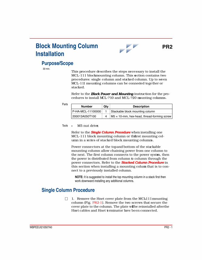
WBPEEUI210507A0 PR2 - 1
PR2Block Mounting Column Installation
Purpose/ScopeThis procedure describes the steps necessary to install the MCL-111 block mounting column. This section contains two procedures: single column and stacked column. Up to seven MCL-111 mounting columns can be connected together or stacked.
Refer to the Block Power and MountingBlock Power and MountingBlock Power and MountingBlock Power and Mounting instruction for the pro-cedures to install MCL-?10 and MCL-?20 mounting columns.
Parts
Tools • M5 nut driver.
Refer to the Single Column ProcedureSingle Column ProcedureSingle Column ProcedureSingle Column Procedure when installing one MCL-111 block mounting column or the first mounting col-umn in a series of stacked block mounting columns.
Power connectors at the top and bottom of the stackable mounting column allow chaining power from one column to the next. The first column connects to the power system, then the power is distributed from column to column through the power connectors. Refer to the Stacked Column ProcedureStacked Column ProcedureStacked Column ProcedureStacked Column Procedure in this section when installing a mounting column that is to con-nect to a previously installed column.
NOTE: It is suggested to install the top mounting column in a stack first then work downward installing any additional columns.
Single Column Procedure□ 1. Remove the Hnet cover plate from the MCL-111 mounting
column (Fig. PR2-1). Remove the two screws that secure the cover plate to the column. The plate will be reinstalled after the Hnet cables and Hnet terminator have been connected.
30 min.
Number Qty DescriptionP-HA-MCL-11100000 1 Stackable block mounting column200013A050T100 4 M5 × 10-mm, hex-head, thread-forming screw

PR2 - 2 WBPEEUI210507A0
Single Column Procedure
□ 2. Align then attach the block mounting column to the col-umn mounting bars using four M5 screws (Fig. PR2-2). Make sure the column is lined up with other installed columns so that the block cooling vents will line up.
If installing in an enclosure that does not have a cooling fan assembly, the horizontal location of the column is not fixed. Determine column spacing based on the desired wiring chan-nel width.
If installing in an enclosure with a cooling fan assembly, the column must be mounted so that the SIM-100 module vents line up with the cooling assembly nozzle. Position the column so that the right side of the column lines up with the top, right side of the nozzle.
Figure PR2-1. Hnet Cover Plate Removal
H N E TC OV E R P LATE
SC R EW S (2)
T037 40A

Stacked Column Procedure
WBPEEUI210507A0 PR2 - 3
Stacked Column Procedure□ 1. Remove the Hnet cover plate from the MCL-111 mounting
column (Fig. PR2-1). Remove the two screws that secure the cover plate to the column. The plate will be reinstalled after the Hnet cables and Hnet terminator have been connected.
□ 2. Align the simulation mounting column directly under a previously installed MCL-111 mounting column (Fig. PR2-3).
□ 3. Slide the column up to make the power connection.
□ 4. Attach the column to the mounting bars using four M5 screws.
Figure PR2-2. Single Column Attachment
T03741A
B LOC K M O U N TIN GC O LU M N
C O LU M N M O U N TIN GB AR (2)
S C RE W (4)

PR2 - 4 WBPEEUI210507A0
Stacked Column Procedure
Figure PR2-3. Stacked Column Attachment
T03744A
B LO C K M O UN TIN GC O LU M N
S C RE W (4)

WBPEEUI210507A0 PR3 - 1
PR3SIM-100 Base Installation
Purpose/ScopeThis procedure gives the steps required to install a SIM-100 base.
Parts None.
Tools • Phillips screwdriver.
Procedure□ 1. Verify the block location. The SIM-100 block mounts on an
MCL-111 mounting column.
□ 2. Position the base on the mounting column. Insert the tabs at the back, left side of the base into the slots in the column as shown in Figure PR3-1. Tilt the base slightly to properly insert the tabs. The base is properly positioned when the posts on the back of the base line up with the alignment holes in the column. The mounting column connectors should protrude through the base.
□ 3. Tighten the two captive screws to attach the base to the column.
□ 4. Verify the back of the base is flush with the mounting column.
5 min.

PR3 - 2 WBPEEUI210507A0
Procedure
Figure PR3-1. SIM-100 Base Attachment
T03734A
ALIGNMENTHOLES
INSERT TABSIN SLOTS
CAPTIVEFASTEN INGSCREWS
REAR VIEW

WBPEEUI210507A0 PR4 - 1
PR4SIM-100 Module Installation
Purpose/ScopeThis procedure gives the steps required to install a SIM-100 module.
NOTE: Always follow the instructions given in Special Handling in Section 3 when handling the SIM-100 module.
Parts None.
Tools • Flat-blade screwdriver.
Safety Considerations
Procedure□ 1. Verify the block location. SIM-100 modules are keyed to
compatible SIM-100 bases to prevent a mismatch.
□ 2. Grasp the retractable handle when inserting the module. Insure the handle is extended completely so that the fastening screw does not stick out from the back of the module (Fig. PR4-1).
□ 3. Position the module on the base. It is properly positioned when the posts protruding from the base line up with the align-ment holes on the back of the module.
NOTE: Do not use the fastening screw to align the module.
□ 4. Gently push the module in until the front of the base and the front of the module are flush. This should not require much pressure. If the module cannot be pushed in flush with the base, then either it is not properly aligned or it is not com-patible with the particular base.
1 min.
WARNING1. A SIM-100 module should not be inserted or removed withpower applied when located in a class I, division 2 hazardouslocation unless the area is known to be nonhazardous.
W1

PR4 - 2 WBPEEUI210507A0
Procedure
□ 5. Tighten the captive front panel fastening screw. The fasten-ing screw actually threads into the mounting column and not into the base. Do not overtighten.
Figure PR4-1. SIM-100 Module Attachment
T03735A
ALIGNMENTPOSTS
FASTEN INGSCREW
RETRACTABLEHANDLE

WBPEEUI210507A0 PR5 - 1
PR5SIM-100 Setup
Purpose/ScopeThis procedure gives the steps required to set up the SIM-100 block for proper operation. This includes setting switches, veri-fying and setting jumpers, and checking for fuses.
Parts None.
Tools • Small-tipped, flat-blade screwdriver.• Needlenose pliers (optional).
Procedure□ 1. Verify the heartbeat jumper E1 on the SIM-100 base is set
as shown in Table PR5-1; refer to Figure PR5-1 for the jumper location. This jumper only affects the RJ-45 port operation.
□ 2. Set the special operations switch SW5 located on the back of the module (Table PR5-2).
15 min.
Table PR5-1. Jumper E1 (Base) - Heartbeat
Option1 E1 DescriptionDisable Disable heartbeat signalC
BA
Table PR5-2. Switch SW5 (Module) - Special Operations
Pole Setting Function1/2/3/4 0 Normal operation.5 0 Diagnostic port: disable XON/XOFF (hardware flow
control).1 Not used.
61 0 Diagnostic port: 9,600 baud.1 Not used.

PR5 - 2 WBPEEUI210507A0
Procedure
□ 3. Remove the access cover from the right side of the module (Fig. PR5-2).
□ 4. Verify the machine fault timer (MFT) jumper E1 is inserted to enable the MFT timer (Fig. PR5-3). The machine fault timer jumper is for ABB use only. Always operate the SIM-100 mod-ule with the machine fault timer circuit enabled. Unpredictable module operation could occur if disabled.
□ 5. The SIM-100 block is a node on the Simulation LAN (i.e., Ethernet). Set switches SW1 through SW4 to the IP address assigned to the block. The address must be converted to binary format to set the switches. Table PR5-3 provides examples of IP address settings.
□ 6. Replace the access cover.
□ 7. Verify 1.6 A, 250 V fuses are present in both the BLP A and BLP B block power fuse holders on the SIM-100 module.
7/8 0/0 Normal operation.0/1 Firmware upgrade from diagnostic port.1/0 Enable diagnostics (for ABB use only).1/1 Not used.
NOTE: 1 = open or off, 0 = closed or on.1. Diagnostic port has the following fixed characteristics: no parity, eight data bits, and one stop bit.
Table PR5-2. Switch SW5 (Module) - Special Operations (continued)
Pole Setting Function
Table PR5-3. Switches SW1 through SW4 (Module) - Example IP Address Settings
AddressSW4 SW3 SW2 SW1
1 2 3 4 5 6 7 8 1 2 3 4 5 6 7 8 1 2 3 4 5 6 7 8 1 2 3 4 5 6 7 810.41.4.17 0 0 0 0 1 0 1 0 0 0 1 0 1 0 0 1 0 0 0 0 0 1 0 0 0 0 0 1 0 0 0 1177.12.1.28 1 0 1 1 0 0 0 1 0 0 0 0 1 1 0 0 0 0 0 0 0 0 0 1 0 0 0 1 1 1 0 0NOTE: 0 = on or closed; 1 = off or open.1. Pole one for each switch is the most significant bit.

Procedure
WBPEEUI210507A0 PR5 - 3
Figure PR5-1. SIM-100 Base
HEARTBEATJUMPER
T03747A
P3
P4
E1CBA

PR5 - 4 WBPEEUI210507A0
Procedure
Figure PR5-2. SIM-100 Module Switch and Jumper Access
T03745A
PROCESSORBOARD
ACCESSCOVER

Procedure
WBPEEUI210507A0 PR5 - 5
Figure PR5-3. SIM-100 Module Board Layout
SPEC IALOPERATIONS
SW 5
P7 E1
SW 4
SW 3
BLP A
BLP B
IPADDRESS
F1
F2
SW 2
SW 1
MACH INE FAULTTIMER
D IAGNOSTICPORT
T03736A

WBPEEUI210507A0
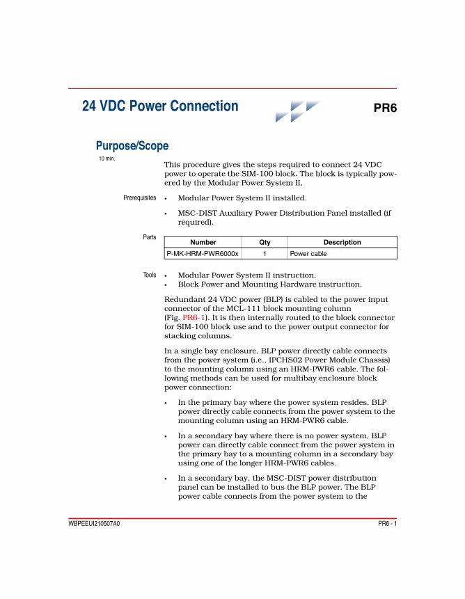
WBPEEUI210507A0 PR6 - 1
PR624 VDC Power Connection
Purpose/ScopeThis procedure gives the steps required to connect 24 VDC power to operate the SIM-100 block. The block is typically pow-ered by the Modular Power System II.
Prerequisites • Modular Power System II installed.
• MSC-DIST Auxiliary Power Distribution Panel installed (if required).
Parts
Tools • Modular Power System II instruction.• Block Power and Mounting Hardware instruction.
Redundant 24 VDC power (BLP) is cabled to the power input connector of the MCL-111 block mounting column (Fig. PR6-1). It is then internally routed to the block connector for SIM-100 block use and to the power output connector for stacking columns.
In a single bay enclosure, BLP power directly cable connects from the power system (i.e., IPCHS02 Power Module Chassis) to the mounting column using an HRM-PWR6 cable. The fol-lowing methods can be used for multibay enclosure block power connection:
• In the primary bay where the power system resides, BLP power directly cable connects from the power system to the mounting column using an HRM-PWR6 cable.
• In a secondary bay where there is no power system, BLP power can directly cable connect from the power system in the primary bay to a mounting column in a secondary bay using one of the longer HRM-PWR6 cables.
• In a secondary bay, the MSC-DIST power distribution panel can be installed to bus the BLP power. The BLP power cable connects from the power system to the
10 min.
Number Qty DescriptionP-MK-HRM-PWR6000x 1 Power cable

PR6 - 2 WBPEEUI210507A0
Procedure
distribution panel, then from the distribution panel to the mounting column. An HRM-PWR6 cable is used to connect between the mounting column and the distribution panel.
Refer to the Modular Power System IIModular Power System IIModular Power System IIModular Power System II and Block Power and Mounting Hardware instructions for further explanation and power connection details.
Procedure□ 1. Attach the appropriate end of the HRM-PWR6 power cable
to the power input connector of the MCL-111 block mounting column (Fig. PR6-1).
□ 2. Connect the other end of the power cable to the power source as described in the following paragraphs.
Figure PR6-1. 24 VDC Power Connectors
P OW E R IN
P OW E R O U T T 0376 4A

Procedure
WBPEEUI210507A0 PR6 - 3
• If connecting directly to the Modular Power System II, attach the HRM-PWR6 cable to an available connector (P1 through P10) on the IPCHS02 chassis. Refer to the Modu-lar Power System II instruction.
• If connecting directly to the Modular Power System II through an MSC-DIST distribution panel, attach the HRM-PWR6 cable to an available connector (P1 through P4 and P6 through P9) on the distribution panel. Refer to the Block Power and Mounting Hardware instruction.

WBPEEUI210507A0

WBPEEUI210507A0 PR7 - 1
PR7Hnet Connection
Purpose/ScopeThis procedure describes Hnet connection and termination.
Parts
Tools • Harmony Bridge Controller instruction.• Harmony Communications Network (Hnet) instruction.
An intracabinet Hnet segment must be properly terminated at both ends. When used for simulation, one end of the Hnet seg-ment terminates at the mounting column and the other end terminates at the controller. Refer to the Harmony Communi-Harmony Communi-Harmony Communi-Harmony Communi-cations Network (Hnet)cations Network (Hnet)cations Network (Hnet)cations Network (Hnet) instruction for a description of Hnet, Hnet specifications, Hnet terminators, and additional Hnet related information.
ProcedureFigure PR7-1 shows standard Hnet connection for simulated I/O in a single Harmony controller. Figure PR7-2 shows stan-dard Hnet connection for simulated I/O in multiple Harmony controllers. Figure PR7-3 shows standard Hnet connections for simulated I/O and nonredundant real I/O in a single Har-mony controller. Figure PR7-4 shows standard Hnet connec-tions for simulated I/O and redundant real I/O in a single Harmony controller.
NOTE: Columns cannot be connected together in a way that would put more than one SIM-100 block on the same Hnet.The controller supports one SIM-100 block.
□ 1. Make the necessary cable connections as shown in Figures PR7-1 through PR7-4. Connect the Hnet cable from the con-troller to the top Hnet connector on the MCL-111 mounting column. Refer to the Harmony Bridge ControllerHarmony Bridge ControllerHarmony Bridge ControllerHarmony Bridge Controller or Harmony Harmony Harmony Harmony Communications Network (Hnet) Communications Network (Hnet) Communications Network (Hnet) Communications Network (Hnet) instruction for controller to
10 min.
Number Qty DescriptionP-HA-MSC-TER20000 1 Hnet terminatorP-MK-HRM-MCL1000x System dependent Column to column Hnet cable

PR7 - 2 WBPEEUI210507A0
Procedure
mounting column connection options including the cable to use.
□ 2. Install an MSC-TER2 Hnet terminator in the location shown in Figures PR7-1 through PR7-4. Figure PR7-5 shows the MSC-TER2 Hnet terminator.
□ 3. Install the Hnet cover plate (Fig. PR7-6). Use the two screws previously removed to attach the cover plate to the mounting column.
□ 4. When all required cable connections are made and all required terminators are installed there should be no open Hnet connectors on any mounting column. Verify there are no open Hnet connectors.
Figure PR7-1. Single MCL-111 Column Hnet Connections
TO CONTROLLER
HNETTERM INATOR
T03765A

Procedure
WBPEEUI210507A0 PR7 - 3
Figure PR7-2. Multiple MCL-111 Column Hnet Connections
Figure PR7-3. MCL-111 to MCL-?10 Column Hnet Connections
TO CONTROLLER 1
TO CONTROLLER 2
TO CONTROLLER 3
HNET TERM INATOR
HNET TERM INATOR
HNET TERM INATOR
T03860A
TO CONTROLLER
HRM-MCL
HNETTERM INATOR
T03766A

PR7 - 4 WBPEEUI210507A0
Procedure
Figure PR7-4. MCL-111 to MCL-?20 Column Hnet Connections
Figure PR7-5. MSC-TER2 Hnet Terminator
TO CONTROLLER
HRM -MCLHNETTERM INATOR
T03767AHRM -MCL
T03151A
P1
TB2
TB1
COM
COM
SOA1
SOA2

Procedure
WBPEEUI210507A0 PR7 - 5
Figure PR7-6. Hnet Cover Plate Installation
HNETCOVER PLATE
SCREWS (2)
T03740A

WBPEEUI210507A0

WBPEEUI210507A0 PR8 - 1
PR8Simulation LAN Connection
Purpose/ScopeThis procedure describes Simulation LAN connection (i.e., Ethernet). The Simulation LAN supports 10Base2 (thin coax-ial), 10Base5 (thick coaxial), 10BaseT (category 5, unshielded twisted-pair), and 10BaseFL (fiber optic) cable. Standard Ethernet equipment and network topologies can be used when connecting to the network.
The preferred Simulation LAN connection method is 10BaseT cable. A transceiver is not required for this connection. An Ethernet switch is recommended for connecting Simulation LAN segments.
Parts
Tools Phillips screwdriver (required for transceiver installation).
The Simulation LAN signals are isolated. 12 VDC and ground are provided to the transceiver, nonisolated, at the AUI port. AUI power isolation and additional network signal isolation are provided by the transceiver.
Procedure□ 1. For 10BaseT, connect a twisted-pair cable (category 5,
unshielded) terminated with an RJ-45 connector to the RJ-45 port (P4) on the SIM-100 base (Fig PR8-2).
-orororor-
Connect a 10Base2, 10Base5, or 10BaseFL transceiver to the DB-15 AUI port (P3) on the SIM-100 base (Fig PR8-2). Depend-ing on the model, the transceiver either connects directly to
10 min.
Number Qty DescriptionP-HA-MSC-SIMBNC00 1 10Base2 transceiverNot applicable 10Base5 transceiver and AUI cableNot applicable 10BaseFL transceiver

PR8 - 2 WBPEEUI210507A0
Procedure
the AUI port or it requires an AUI cable connected between the AUI port and the transceiver port.
NOTE: Follow the transceiver manufacturer’s instructions on how to configure the SQE (heartbeat) signal and how to install retaining brackets if applicable.
□ 2. If connecting a 10Base2 or 10BaseFL transceiver, install the transceiver bracket provided using two M4 screws and washers (provided) in the location shown in Figures PR8-3 and PR8-5. Locate the rubber spacers between the bracket and transceiver (optional).
□ 3. Make the Simulation LAN connection as appropriate. Figures PR8-3 through PR8-1 provide some example connec-tion methods.
NOTES: 1. The SIM-100 block supports one Simulation LAN connection. The RJ-45 port and AUI port are mutually exclusive. An RJ-45 port connection cannot be made if there is already an AUI port connection and vice versa. The SIM-100 module will automatically switch the internal Ethernet circuitry to the AUI port or RJ-45 port depending one where it senses activity.
2. The example Ethernet connections shown in Figures PR8-3 and PR8-4 are with the SIM-100 block located at the end of an Ethernet segment. The 50 ohm terminator may be located in a different place depending on the location of the block on the segment.

Procedure
WBPEEUI210507A0 PR8 - 3
Figure PR8-1. 10BaseT Example Connection
T 03751A
P 3
P4
E1CBA
TW IS TE D -PAIRC A B LE
R J-45C O N N EC TO R
TO10BASE TSW ITC HO R H U B

PR8 - 4 WBPEEUI210507A0
Procedure
Figure PR8-2. SIM-100 Base
R J-45 P O RTTW IS TED PA IR
AU I P O RT
T 03746A
P 3
P4
E1CBA

Procedure
WBPEEUI210507A0 PR8 - 5
Figure PR8-3. 10Base2 Example Connection
T03753A
P 3
P 4
E1CBA
10BASE2TR AN SC EIVER
TH IN C OAXIALC ABLE
BN CC O N N EC TO R S
BN C 50TER M IN ATO R
τ TR AN SC EIVERBR AC KET
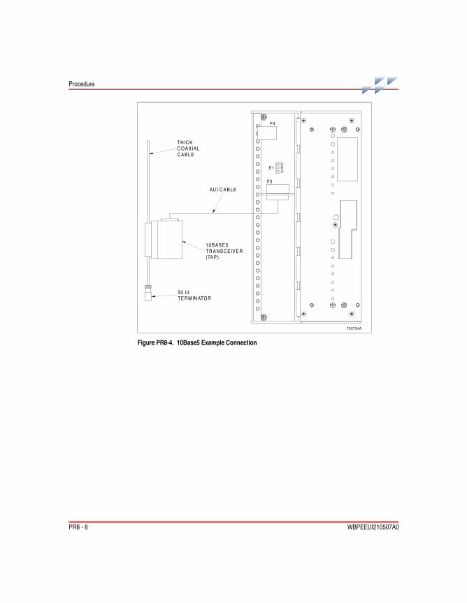
PR8 - 6 WBPEEUI210507A0
Procedure
Figure PR8-4. 10Base5 Example Connection
T03754A
P3
P 4
E 1CBA
50TE R M IN ATO R
τ
10BASE5TR AN SC EIVE R(TA P)
AU I C ABLE
TH IC KC OAXIALC ABLE
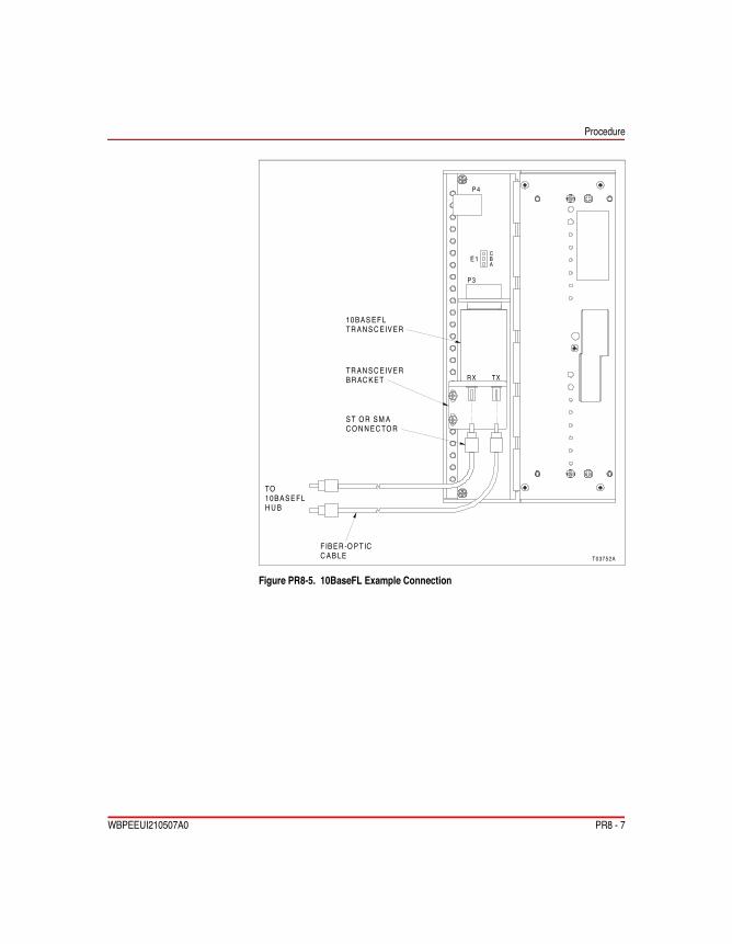
Procedure
WBPEEUI210507A0 PR8 - 7
Figure PR8-5. 10BaseFL Example Connection
T03752A
P 3
P 4
E 1CBA
10BAS EFLTR AN SC EIVER
FIBER -O PTICC AB LE
TO10BASEFLH U B
ST O R SM AC O N N EC TO R
TR AN SC EIVERBR AC KET R X TX

WBPEEUI210507A0

WBPEEUI210507A0 PR9 - 1
PR9Connections Check
Purpose/ScopeThis procedure explains how to check connections. Check all signal wiring, power, ground, and cable connections within the enclosure to verify their integrity.
Parts None.
Tools • Flat-blade screwdriver.• Phillips screwdriver.
Safety Considerations
ProcedureWhen checking connections, always turn a screw, nut, or other fastening device in the direction to tighten only. If the connec-tion is loose, it will be tightened. If the connection is tight, the tightening action will verify that it is secure. There should notnotnotnot be any motion done to loosen the connection.
NOTE: ABB Automation recommends this preventive maintenance task be performed during power supply preventive maintenance while the power to the enclosure is off.
□ 1. Verify that power is removed before checking any connec-tions for tightness.
□ 2. Verify that all field wiring connections are secure.
□ 3. Verify that all power wiring connections are secure.
□ 4. Check all cable connections.
10 min.
WARNING1. Turn off all power before attempting the connections checkmaintenance procedure. Failure to do so could result in severeor fatal shock, or equipment damage.
W1

WBPEEUI210507A0

WBPEEUI210507A0 PR10 - 1
PR10SIM-100 Module Removal
Purpose/ScopeThis procedure gives the steps required to remove a SIM-100 module from its base.
NOTE: Always follow the instructions given in Special Handling in Section 3 when handling the SIM-100 module.
Parts None.
Tools • Flat-blade screwdriver.• Thin rod for reset button, preferably nonmetallic.
Safety Considerations
Procedure□ 1. Depress the stop/reset button once to halt block operation
if not already halted.
□ 2. Loosen the captive front panel fastening screw (Fig. PR10-1).
□ 3. Grasp the module by its handle and gently pull.
1 min.
WARNING1. A SIM-100 module should not be inserted or removed withpower applied when located in a class I, division 2 hazardouslocation unless the area is known to be nonhazardous.
W1

PR10 - 2 WBPEEUI210507A0
Procedure
Figure PR10-1. SIM-100 Module Removal
T03735A
ALIGNMENTPOSTS
FASTEN INGSCREW
RETRACTABLEHANDLE

WBPEEUI210507A0 PR11 - 1
PR11SIM-100 Base Removal
Purpose/ScopeThis procedure gives the steps required to remove a SIM-100 base.
Parts None.
Tools • Phillips screwdriver.
Procedure□ 1. Loosen the two captive screws that attach the base to the
column (Fig. PR11-1).
□ 2. Slide the base to the right so the tabs on the back of the base clear the slots in the column as shown in Figure PR11-1, then remove the base.
5 min.

PR11 - 2 WBPEEUI210507A0
Procedure
Figure PR11-1. SIM-100 Base Removal
T03734A
ALIGNMENTHOLES
INSERT TABSIN SLOTS
CAPTIVEFASTEN INGSCREWS
REAR VIEW

WBPEEUI210507A0 Index - 1
Index
BBase ...............................2-8, PR3-1, PR11-1Benefits..................................................... 1-6Block power ....................2-6, 4-3, 5-1, PR6-1Block status ....................................... 4-1, 5-3BRC-100................................................... 1-3
CCablesHnet .................................................. PR7-1Nomenclature ........................................ 8-1Simulation LAN ................................. PR8-1
Communication status .............................. 4-3Compatibility ............................................. 1-6Connections check .............................. PR9-1Connectors ............................................... 5-5Controller .................................................. 1-3
DDesign standards.................................... 1-12Diagnostics ............................................... 5-5Dimensions...............................................A-1DocumentHow to use............................................. 1-8Instruction content ................................. 1-7Intended user......................................... 1-7
EEthernet .................................................... 2-4
FFAULT ...................................................... 4-1Features ................................................... 1-6Front panel ............................................... 4-1
GGlossary ................................................... 1-9
HHardware drawings .................................. A-1Hardware keying .......................................2-9Harmony bridge controller.........................1-3Heartbeat jumper (E1)..........................PR5-1Hnet...............................................1-4, PR7-1
II/O expander bus.......................................1-5Installation .................................................3-1IP address (SW1, SW2,SW3, SW4) ...................................2-8, PR5-2
JJumperHeartbeat (E1)...................................PR5-1MFT (E1) ...........................................PR5-2
MMaintenance..............................................6-1Module ........................... 2-2, PR4-1, PR10-1Mounting hardware ...................................2-9Block mounting column ............2-10, PR2-1Column mounting bar.................2-9, PR1-1Installation ..............................................3-2Signal distribution.................................2-11
NNomenclature...................................1-11, 8-1NORMAL...................................................4-1
OOverview ...................................................1-1
PParts..........................................................8-1Pin assignments........................................5-5

Index (continued)
Index - 2 WBPEEUI210507A0
Preventive maintenance schedule ............6-1Procedure24 VDC power connection ................PR6-1Block mounting column installation ...PR2-1Column mounting bar installation......PR1-1Connections check............................PR9-1Hnet connection ................................PR7-1SIM-100 base installation..................PR3-1SIM-100 base removal ....................PR11-1SIM-100 module installation..............PR4-1SIM-100 module removal ................PR10-1SIM-100 setup...................................PR5-1Simulation LAN connection ...............PR8-1
RRear panel ................................................4-5Reference documents .............................1-10Repair .......................................................7-1Replacement .............................................7-1
SSIM-100 .............................................1-5, 2-1Base .......................................................2-8
Connectors ............................................ 5-5Front panel ............................................ 4-1Installation ............................................. 3-2Module................................................... 2-2Nomenclature ........................................ 8-1Rear panel ............................................. 4-5Replacement ......................................... 7-1Startup ................................................... 4-5Stop/reset .............................................. 4-6
Simulation architecture ............................. 1-2Simulation LAN......................1-6, 2-4, PR8-1Special operations (SW5)............. 2-8, PR5-1Specifications ......................................... 1-13Startup...................................................... 4-5Stimulated simulation ............................... 1-1Stop/reset .......................................... 2-8, 4-6SwitchSW1, SW2, SW3, SW4 ............. 2-8, PR5-2SW5........................................... 2-8, PR5-1
TTroubleshooting........................................ 5-1

Form WBPEEUI210507A0 Litho in U.S.A. 899Copyright © 1999 by ABB Automation Inc., as an Unpublished Work® Registered Trademark of Elsag Bailey Process Automation™ Trademark of Elsag Bailey Process Automation
For the latest information on ABB and Year 2000 Product Compatibility Visit us on the World Wide Web at http://www.abb.com
Our worldwide staff of professionals is ready to meet your needs for process automation.For the location nearest you, please contact the appropriate regional office.
GermanyIndustriestrasse 28D-65760 EschbornGermanyTelephone 49-6196-800-0Telefax 49-6196-800-1119
Europe, Africa, Middle EastVia Puccini 216154 Genoa, ItalyTelephone 39-010-6584-943Telefax 39-010-6584-941
Asia/Pacific539 Yishun Industrial Park ASingapore 768740Telephone 65-756-7655Telefax 65-756-7309
Americas29801 Euclid AvenueWickliffe, Ohio USA 44092Telephone 1-440-585-8500Telefax 1-440-585-8756