instruction flow techniques
TRANSCRIPT

55:132/22C:160 Spring, 2009
Jon Kuhl 1
Superscalar TechniquesPart 1: Instruction Flow
Instruction Flow Techniques
• Goal and Impediments
• Branch Types and Implementations
• What’s So Bad About Branches?
• What are Control Dependences?
• Impact of Control Dependences on Performance
• Improving I-Cache Performance
Instruction Flow in Context
I-cache
FETCH
DECODE
BranchPredictor Instruction
Buffer
InstructionFlow
COMMIT
D-cacheStoreQueue
ReorderBuffer
Integer Floating-point Media Memory
RegisterData
MemoryData
EXECUTE
(ROB)
Flow
Flow
Goal and Impediments
• Goal of Instruction Flow– Supply processor with maximum number of
useful instructions every clock cycle
• Impedimentsp– Branches and jumps– I-Cache limitations
• hit rate• width• alignment• etc.

55:132/22C:160 Spring, 2009
Jon Kuhl 2
Branch Types and Implementation
1. Types of BranchesA. Conditional or UnconditionalB. Save PC? Save other processor state?C. How is target computed?g p
• constant target (immediate, PC-relative)• variable target (register, register + offset)
2. Branch ArchitecturesA. Condition code or condition registersB. Register
What’s So Bad About Branches?
• Effects of Branches– Fragmentation of I-Cache lines
– Need to determine branch outcome
Need to determine branch target– Need to determine branch target
– Use up execution resources
What’s So Bad About Branches?
Problem: Fetch stalls until outcome is determined
Solutions:• Minimize delay
– Move instructions determining branch condition away g yfrom branch
• Make use of delay– Non-speculative:
• Fill delay slots with useful safe instructions• Execute both paths (eager execution)
– Speculative:• Predict branch outcome
What’s So Bad About Branches?
Problem: Fetch stalls until branch target is determined
Solutions:
• Minimize delay
– Generate branch target early– Generate branch target early
• Make use of delay: Predict branch target
– Single target (constant—only need to compute once)
– Multiple targets (variable—but may use previous target value as prediction for next time).

55:132/22C:160 Spring, 2009
Jon Kuhl 3
Control DependencesBB 1
BB 2
BB 3 BB 4
main: addi r2, r0, A addi r3, r0, B addi r4, r0, C BB 1 addi r5, r0, N add r10,r0, r0 bge r10,r5, end loop: lw r20, 0(r2) lw r21, 0(r3) BB 2 bge r20,r21,T1
sw r21 0(r4) BB 3
• Control Flow Graph– Shows possible paths of control flow through basic
blocks
BB 5
sw r21, 0(r4) BB 3 b T2 T1: sw r20, 0(r4) BB 4 T2: addi r10,r10,1 addi r2, r2, 4 addi r3, r3, 4 BB 5 addi r4, r4, 4 blt r10,r5, loop end:
Control DependencesBB 1
BB 2
BB 3 BB 4
main: addi r2, r0, A addi r3, r0, B addi r4, r0, C BB 1 addi r5, r0, N add r10,r0, r0 bge r10,r5, end loop: lw r20, 0(r2) lw r21, 0(r3) BB 2 bge r20,r21,T1
sw r21 0(r4) BB 3
• Control Dependence– Node B is CD on Node A if A determines whether
B executes
BB 5
sw r21, 0(r4) BB 3 b T2 T1: sw r20, 0(r4) BB 4 T2: addi r10,r10,1 addi r2, r2, 4 addi r3, r3, 4 BB 5 addi r4, r4, 4 blt r10,r5, loop end:
Limits on Instruction Level Parallelism (ILP)
Weiss and Smith [1984] 1.58
Sohi and Vajapeyam [1987] 1.81
Tjaden and Flynn [1970] 1.86 (Flynn’s bottleneck)
Tjaden and Flynn [1973] 1.96
Uht [1986] 2.00
Smith et al. [1989] 2.00
Jouppi and Wall [1988] 2.40
Johnson [1991] 2.50
Acosta et al. [1986] 2.79
Wedig [1982] 3.00
Butler et al. [1991] 5.8
Melvin and Patt [1991] 6
Wall [1991] 7 (Jouppi disagreed)
Kuck et al. [1972] 8
Riseman and Foster [1972] 51 (no control dependences)
Nicolau and Fisher [1984] 90 (Fisher’s optimism)
Riseman and Foster’s Study• 7 benchmark programs on CDC-3600• Assume infinite machines
– Infinite memory and instruction stack– Infinite register file– Infinite functional units– True dependencies only at dataflow limit
• If lookahead bounded to single basic block, speedup is 1.72 (Flynn’s bottleneck)
• If one can bypass branches (hypothetically), then: a theoretical ILP of 51 was determined by Riseman and Foster

55:132/22C:160 Spring, 2009
Jon Kuhl 4
Program Control Flow
• Implicit Sequential Control Flow– Static Program Representation
• Control Flow Graph (CFG)• Nodes = basic blocks• Edges = Control flow transfers
– Physical Program Layout• Mapping of CFG to linear program memory• Implied sequential control flow
13
• Implied sequential control flow
– Dynamic Program Execution• Traversal of the CFG nodes and edges (e.g. loops)• Traversal dictated by branch conditions
– Dynamic Control Flow• Deviates from sequential control flow• Disrupts sequential fetching• Can stall IF stage and reduce I-fetch bandwidth
Program Control Flow
• Dynamic traversal of static CFG
• Mapping CFG to linear memory
14
(a) (b)
Disruption of Sequential Control Flow
Instruction/Decode Buffer
Fetch
Dispatch Buffer
Decode
Dispatch
15
Reservation
Reorder/
Store Buffer
Complete
Retire
StationsIssue
Execute
FinishCompletion Buffer
Branch
Branch Prediction
• Target address generation Target Speculation– Access register:
• PC, General purpose register, Link register
– Perform calculation:
16
• +/- offset, autoincrement, autodecrement
• Condition resolution Condition speculation– Access register:
• Condition code register, General purpose register
– Perform calculation:• Comparison of data register(s)

55:132/22C:160 Spring, 2009
Jon Kuhl 5
Target Address Generation
Decode Buffer
Fetch
Dispatch Buffer
Decode
Reservation
Dispatch
PC-rel.
Reg.ind.
Reg.ind.withoffset
17
Reservation
Store Buffer
Complete
Retire
StationsIssue
Execute
Finish Completion Buffer
Branch
Condition Resolution
Decode Buffer
Fetch
Dispatch Buffer
Decode
Reservation
Dispatch
CCreg.
GPreg.valuecomp.
18
Reservation
Store Buffer
Complete
Retire
StationsIssue
Execute
Finish Completion Buffer
Branch
Branch Instruction Speculation
Decode Buffer
Fetch
Di t h B ff
Decode
to I-cache
PC(seq.) = FA (fetch address)PC(seq.)Branch
Predictor(using a BTB)
Spec. target
BTBupdate
Prediction
(t t dd
Spec. cond.
FA-mux
19
Dispatch Buffer
Reservation
Dispatch
StationsIssue
Execute
Finish Completion Buffer
Branch
(target addr.and history)
Branch/Jump Target Prediction
• Branch Target Buffer: small cache in fetch stage
Branch inst. Information Branch targetaddress for predict. address (most recent)
20
• Branch Target Buffer: small cache in fetch stage– Previously executed branches, address, taken history, target(s)
• Fetch stage compares current FA against BTB– If match, use prediction– If predict taken, use BTB target
• When branch executes, BTB is updated• Optimization:
– Size of BTB: increases hit rate– Prediction algorithm: increase accuracy of prediction

55:132/22C:160 Spring, 2009
Jon Kuhl 6
Branch Prediction: Condition Speculation
1. Biased Not Taken– Hardware prediction– Does not affect ISA– Not effective for loops
2. Software Prediction– Extra bit in each branch instruction
• Set to 0 for not taken
21
Set to 0 for not taken• Set to 1 for taken
– Bit set by compiler or user; can use profiling– Static prediction, same behavior every time
3. Prediction based on branch offset– Positive offset: predict not taken– Negative offset: predict taken
4. Prediction based on dynamic history
Branch Prediction: Condition Speculation
1. Biased Not Taken– Hardware prediction– Does not affect ISA– Not effective for loops
2. Software Prediction– Extra bit in each branch instruction
• Set to 0 for not taken
Biased Taken• Predict “Taken” for BTAB hits•Predict “Not Taken” for BTAB misses
2222
Set to 0 for not taken• Set to 1 for taken
– Bit set by compiler or user; can use profiling– Static prediction, same behavior every time
3. Prediction based on branch offset– Positive offset: predict not taken– Negative offset: predict taken
4. Prediction based on dynamic history
UCB Study [Lee and Smith, 1984]• Benchmarks used
– 26 programs (IBM 370, DEC PDP-11, CDC 6400)
– 6 workloads (4 IBM, 1 DEC, 1 CDC)
– Used trace-driven simulation
• Branch types– Unconditional: always taken or always not taken
– Subroutine call: always taken
– Loop control: usually taken
– Decision: either way, if-then-else
– Computed goto: always taken, with changing target
23
p g y , g g g
– Supervisor call: always taken
– Execute: always taken (IBM 370)
IBM1 IBM2 IBM3 IBM4 DEC CDC Avg
T 0.64 0.65 0.70 0.54 0.73 0.77 0.67
NT 0.36 0.34 0.29 0.46 0.26 0.22 0.32
Branch Prediction Function
• Prediction function F(X1, X2, … )– X1 – opcode type
– X2 – history
• Prediction effectiveness based on opcode only, or history
IBM1 IBM2 IBM3 IBM4 DEC CDC
Opcode 66 69 71 55 80 78
24
Opcode only
66 69 71 55 80 78
History 1 92 95 87 80 97 82
History 2 93 97 91 83 98 91
History 3 94 97 91 84 98 94
History 4 95 97 92 84 98 95
History 5 95 97 92 84 98 96

55:132/22C:160 Spring, 2009
Jon Kuhl 7
Example Prediction Algorithm
TTT
N
T
NTT
TNTNNNN
T
TT
N
TTT
Branch inst. Information Branch targetaddress for predict. address
25
• Hardware table remembers last 2 branch outcomes– History of past several branches encoded by FSM– Current state used to generate prediction
• Results:
TNT
TNT N
NN
IBM1 IBM2 IBM3 IBM4 DEC CDC
93 97 91 83 98 91
Other Prediction Algorithms
N
TN
N
T
TNT
n?
t
T
N
N
T
TN
t?
T N
n?
tt?
nn
T
26
• Combining prediction accuracy with BTB hit rate (86.5% for 128 sets of 4 entries each), branch prediction can provide the net prediction accuracy of approximately 80%. This implies a 5-20% performance enhancement.
TT
TNT
T
n?
NN
IBM Study [Nair, 1992]
• Branch processing on the IBM RS/6000– Separate branch functional unit– Five different branch types
• b: unconditional branch• bl: branch and link (subroutine calls)• bc: conditional branch
27
bc: conditional branch• bcr: condor branch using link register (returns)• bcc: conditional branch using count register
– Overlap of branch instructions with other instructions
• Zero cycle branches
– Two causes for branch stalls• Unresolved conditions• Branches downstream too close to unresolved branches
Branch Instruction Distribution
% of each branch type % bc with penalty cycles
Benchmark b bl bc bcr 3 cyc 2 cyc 1 cyc
spice2g6 7.86 0.30 12.58 0.32 13.82 3.12 0.76
doduc 1.00 0.94 8.22 1.01 10.14 1.76 2.02
t i 300 0 00 0 00 14 50 0 00 0 68 0 22 0 20
28
matrix300 0.00 0.00 14.50 0.00 0.68 0.22 0.20
tomcatv 0.00 0.00 6.10 0.00 0.24 0.02 0.01
gcc 2.30 1.32 15.50 1.81 22.46 9.48 4.85
espresso 3.61 0.58 19.85 0.68 37.37 1.77 0.31
li 2.41 1.92 14.36 1.91 31.55 3.44 1.37
eqntott 0.91 0.47 32.87 0.51 5.01 11.01 0.80

55:132/22C:160 Spring, 2009
Jon Kuhl 8
Exhaustive Search for Optimal 2-bit Predictor• There are 220 possible state machines of 2-bit predictors
• Some machines are uninteresting, pruning them out reduces the number of state machines to 5248
• For each benchmark, determine prediction accuracy for all the predictor state machines
• Find optimal 2-bit predictor for each applicationBenchmark Optimal “Counter”
spice2g6 97.2 97.0
N
T
29
doduc 94.3 94.3
gcc 89.1 89.1
espresso 89.1 89.1
li 87.1 86.8
eqntott 87.9 87.2
*
*
*
*
*
*
Initial state Predict NT Predict T
Number of History Bits Needed
Prediction Accuracy (Overall CPI Overhead)
Benchmark 3 bit 2 bit 1 bit 0 bit
spice2g6 97.0 (0.009) 97.0 (0.009) 96.2 (0.013) 76.6 (0.031)
doduc 94.2 (0.003) 94.3 (0.003) 90.2 (0.004) 69.2 (0.022)
gcc 89.7 (0.025) 89.1 (0.026) 86.0 (0.033) 50.0 (0.128)
30
• Branch history table size: Direct-mapped array of 2k entries• Some programs, like gcc, have over 7000 conditional branches• In collisions, multiple branches share the same predictor
– Constructive interference– Destructive interference
• Marginal gains beyond 1K entries (for these programs)
espresso 89.5 (0.045) 89.1 (0.047) 87.2 (0.054) 58.5 (0.176)
li 88.3 (0.042) 86.8 (0.048) 82.5 (0.063) 62.4 (0.142)
eqntott 89.3 (0.028) 87.2 (0.033) 82.9 (0.046) 78.4 (0.049)
Branch Prediction Implementation (PPC 604)
Decode Buffer
Fetch
Dispatch Buffer
Decode
to I-cache
FA (fetch address)FABranch
Predictor
Spec. target
Prediction FA-mux
BranchPredictorUpdate
31
ReservationDispatch
Stations
Issue
Execute
Finish Completion
Branch
SFX SFX CFX FPU LSBRN
Buffer
BTAC and BHT Design (PPC 604)
Decode Buffer
D d
FA
Branch TargetAddress Cache
FA-m
ux
Branch HistoryTable (BHT)
BTAC
BHT
(BTAC)
I-cache
update
FA FA
FA
R
+4
32
Dispatch Buffer
Decode
ReservationDispatch
Stations
Issue
Execute
Finish Completion
Branch
BHT
SFX SFX CFX FPU LSBRN
Buffer
update
BTAC prediction
BHT prediction
BTAC:- 64 entries- fully associative- hit => predict taken
BHT:- 512 entries- direct mapped- 2-bit saturating counter history based prediction- overrides BTAC prediction

55:132/22C:160 Spring, 2009
Jon Kuhl 9
Yeh & Patt Michigan Study, 1992o Two-level adaptive branch prediction:
o First level: History of last k branches encountered
o Second level: branch behavior of the last s occurrences of the specific pattern of these k branches
o Use a Branch History Register (BHR) in conjunction with a Pattern History Table (PHT)
33
o Example: (k=8, s=6)o Last k branches with the behavior (11100101)o History at the entry (11100101) is [101010]
o Using history, branch prediction algorithm predicts direction of the branch
o Effectiveness:o Averaging 97% accuracy for SPECo Used in the Intel P6 and AMD K6
Yeh & Patt Michigan Study, 1992
00...00
00...01
00...10
1 0 1 1 1
Branch History Shift
(shift left when update)
Pattern History Table (PHT)
PHTBits
Register (BHSR)
34
11...10
11...11
Bits
Prediction
Branch Result
index
FSMLogic
old
new
1 1 1 0 0
1 1 1 1 0
To achieve 97% average prediction accuracy:(1) BHR: 18 bits; (1) PHT: 218 x 2 bits(512x4) BHR: 12 bits; (1) PHT: 212 x 2 bits(512x4) BHR: 6 bits; (512) PHT: 26 x 2 bits
Global BHR Scheme (GAs)
ctio
n
Branch Address
Branch HistoryShift Register (BHSR)
j bits
35
Pre
dic
k bits
BHT of 2 x 2 j+k
Per-branch BHSR (PAs)on
Branch Address
Branch HistoryShift Register (BHSR)
j bitsi bits
k x 2i
36
Pre
d ict
io
BHT of 2 x 2 j+kk bits

55:132/22C:160 Spring, 2009
Jon Kuhl 10
Gshare Branch Predictor
n
Branch Address
Branch History
j bits
37
Pre
dict
ionBranch History
Shift Register (BHSR)
k bits
BHT of 2 x 2 max(j,k)
Register Data Flow Techniques
• Register Data Flow– Resolving Anti-dependences (WAR)– Resolving Output Dependences (WAW)– Resolving True Data Dependences (RAW)
• Tomasulo’s Algorithm [Tomasulo 1967]
38
• Tomasulo s Algorithm [Tomasulo, 1967]– Modified IBM 360/91 Floating-point Unit– Reservation Stations– Common Data Bus– Register Tags– Operation of Dependency Mechanisms
The Big Picture
INSTRUCTION PROCESSING CONSTRAINTS
Resource Contention Code Dependences(Structural Dependences)
39
Control Dependences Data Dependences
True Dependences
Anti-Dependences Output Dependences
Storage Con?icts(RAW)
(WAR) (WAW)
Register Data Flow
Each ALU Instruction:INSTRUCTION EXECUTION MODEL
Ri Fn (Rj, Rk)
Dest.Reg.
Funct.Unit
SourceRegisters
R0R1
Rm
FU1
FU2
FUInterconnect
•••
•••
40
Need Availability of Fn (Structural Dependences)
Need Availability of Rj, Rk (True Data Dependences)
Need Availability of Ri (Anti-and output Dependences)
Rm FUn
Registers FunctionalUnits

55:132/22C:160 Spring, 2009
Jon Kuhl 11
Causes of (Register) Storage Conflict
REGISTER RECYCLING
MAXIMIZE USE OF REGISTERS
MULTIPLE ASSIGNMENTS OF VALUES TO REGISTERS
OUT OF ORDER ISSUING AND COMPLETION
LOSE IMPLIED PRECEDENCE OF SEQUENTIAL CODE
LOSE 1-1 CORRESPONDENCE BETWEEN VALUES AND REGISTERS
41
REGISTERS
Ri•••
Ri
••• DEF
USE
USE
DEF•••
Ri
Ri
•••
•••
Contribution to Register RecyclingCOMPILER REGISTER ALLOCATION
INSTRUCTION LOOPS
Single Assignment, Symbolic Reg.
Map Symbolic Reg. to Physical Reg. Maximize Reuse of Reg.
CODE GENERATION
REG. ALLOCATION
For (k=1;k<= 10; k++) t += a [i] [k] * b [k] [j] ;9 $34: mul $14 $7, 40
10 dd $15 $4 $14
42
Reuse Same Set of Reg. in Each Iteration
Overlapped Execution of Different Iterations
[ ] [ ] [ ] [j] ;10 addu $15, $4, $1411 mul $24, $9, 412 addu $25, $15, $2413 lw $11, 0($25)14 mul $12, $9, 4015 addu $13, $5, $1216 mul $14, $8, 417 addu $15, $13, $1418 lw $24, 0($15)19 mul $25, $11, $2420 addu $10, $10, $2521 addu $9, $9, 122 ble $9, 10, $34
Resolving Anti-Dependences
STALL DISPATCHING
(2) R3 R5 + 1
Must Prevent (2) from completing • • •(1) R4 R3 + 1
before (1) is dispatched.
43
DELAY DISPATCHING OF (2)
REQUIRE RECHECKING AND REACCESSING
COPY OPERAND
COPY NOT-YET-USED OPERAND TO PREVENT BEING OVERWRITTEN
MUST USE TAG IF ACTUAL OPERAND NOT-YET-AVAILABLE
RENAME REGISTER
HARDWARE ALLOCATION
Resolving Output Dependences
Must Prevent (3) from completing before (1) completes.
(1) R3 R3 op R5
R3
(3) R3 R5 + 1
•••
•••
44
STALL DISPATCHING/ISSUING
DENOTE OUTPUT DEPENDENCE
HOLD DISPATCHING UNTIL RESOLUTION OF DEPENDENCE
ALLOW DECODING OF SUBSEQUENT INSTRUCTIONS
RENAME REGISTER
HARDWARE ALLOCATION

55:132/22C:160 Spring, 2009
Jon Kuhl 12
Register Renaming
Register Renaming Resolves:
Anti-Dependences Output Dependences
Design of Redundant Registers:
Number:
One
Multiple
Allocation:
Fi d f E h R i t
Architected PhysicalRegisters Registers
45
Fixed for Each Register
Pooled for all Regsiters
Location:
Attached to Register File(Centralized)
Attached to functional units (Distributed)
R1R2
•••
Rn
P1P2•••Pn
•••Pn + k
Register Renaming in the RIOS-I FPU
FPU Register Renaming
Map table32 6
32 33 34 35 36 37 38 39
Free Listhead tail
Pending Target Return Queue
FAD 3 2 1 FAD 3 2 1
OP T S1 S2 S3 OP T S1 S2 S3
46
32 x 6
head
tailrelease
Pending Target Return Queue
Incoming FPU instructions pass through a renaming table prior to decode
The 32 architectural registers are remapped to 40 physical registers
Physical register names are used within the FPU
Complex control logic maintains active register mapping
Simplified FPU Register Model
Resolving True Data Dependences
REGISTER READ
ALU OP
REGISTER WRITE
(1) R2 R1 + 1 • • •(2) R3 R2 • • •(3) R4 R3
47
STALL DISPATCHING
ADVANCE INSTRUCTIONS
“DYNAMIC EXECUTION”
Reservation Station + Complex Forwarding
Out-of-order (OoO) Execution
Try to Approach the “Data-Flow Limit”
(3) R4 R3
Embedded “Data Flow” Engine
Dispatch Buffer
Reservation
Dispatch
Stations
- Read register or- Assign register tag
- Monitor reg. tag- Receive data being forwarded
Issue when all
- Advance instructions to reservation stations
48
Complete
“Dynamic
Completion Buffer
Branch
Execution”
- Issue when all operands ready

55:132/22C:160 Spring, 2009
Jon Kuhl 13
Tomasulo’s Algorithm [Tomasulo, 1967]
Floating Point
Registers FLR
0
2
4
8
Control
Floating
Operand
Stack
FLOSControl
Floating Point
Buffers FLB
1
2
3
4
5
6
Floating Point
Registers (FLR)
Control
0
2
4
8
Control
Floating
Operand
Stack
(FLOS)
Floating Point
Buffers (FLB)
1
2
3
4
5
6
Storage Bus Instruction Unit
49
Ctrl.Ctrl. Ctrl.Ctrl.
Adder
Store
Data
1
2
3
Buffers SDB
Control
DecoderDecoder
Store
Data
1
2
3
Buffers (SDB)
Control
Ctrl.
Adder
To Storage
Result
Sink Source
AdderMultiply/Divide
Result
Sink Source
•
•
Floating PointRegister
(FLR) Bus
Floating PointBuffer
(FLB) Bus
• Result Bus
IBM 360/91 FPU• Multiple functional units (FU’s)
– Floating-point add– Floating-point multiply/divide
• Three register files (pseudo reg-reg machine in floating-point unit)– (4) floating-point registers (FLR)– (6) floating-point buffers (FLB)– (3) store data buffers (SDB)
• Out of order instruction execution:
50
– After decode the instruction unit passes all floating point instructions (in order) to the floating-point operation stack (FLOS).
– In the floating point unit, instructions are then further decoded and issued from the FLOS to the two FU’s
• Variable operation latencies:– Floating-point add: 2 cycles– Floating-point multiply: 3 cycles– Floating-point divide: 12 cycles
• Goal: achieve concurrent execution of multiple floating-point instructions, in addition to achieving one instruction per cycle in instruction pipeline
Dependence MechanismsTwo Address IBM 360 Instruction Format:
R1 <-- R1 op R2
Major dependence mechanisms:
• Structural (FU) dependence = > virtual FU’s– Reservation stations
• True dependence = > pseudo operands + result forwarding– Register tags
51
g g
– Reservation stations
– Common data bus (CDB)
• Anti-dependence = > operand copying– Reservation stations
• Output dependence = > register renaming + result forwarding– Register tags
– Reservation stations
– Common data bus (CDB)
IBM 360/91 FPU
Floating Point
Registers FLR
0
2
4
8
D d
Floating
Operand
Stack
FLOSControl
Floating Point
Buffers FLB
1
2
3
4
5
6
Decoder
Floating PointRegisters (FLR)
Control
0
248
Floating
Operand
Stack
Floating Point
Buffers (FLB)
1234
56
Storage Bus Instruction Unit
Point
BusyBits
•
Tags
(FLOS)
52
Adder
Store
Data
1
2
3
Buffers SDB
Control
Decoder
Store
Data
123
Buffers (SDB)
Control
Result
Multiply/Divide
•
Common Data Bus (CDB)
Adder
FLB BusFLR Bus
CDB ••
•
Tags
Sink TagTag Source Ctrl.Sink TagTag Source Ctrl.
Sink TagTag Source Ctrl.
Sink TagTag Source Ctrl.
Sink TagTag Source Ctrl.
•
Result

55:132/22C:160 Spring, 2009
Jon Kuhl 14
Reservation Stations
• Used to collect operands or pseudo operands (tags).
• Associate more than one set of buffering registers (control, source, sink) with each FU, = > virtual FU’s.
• Add unit: three reservation stations
53
• Add unit: three reservation stations
• Multiply/divide unit: two reservation stations
Common Data Bus (CDB)
• CDB is fed by all units that can alter a register (or supply register values) and it feeds all units which can have a register as an operand.
• Sources of CDB:– Floating-point buffers (FLB)– Two FU’s (add unit and the multiply/divide unit)
• Destinations of CDB:
54
– Reservation stations– Floating-point registers (FLR)– Store data buffers (SDB)
Register Tags
• Every source of a register value must be uniquely identified by its own tag value.– (6) FLB’s
– (5) reservation stations (3 with add unit, 2 with multiply/divide unit)
= = > 4-bit tag is needed to identify the 11 potential sources
55
• Every destination of a register value must carry a tag field.– (5) “sink” entries of the reservation stations
– (5) “source” entries of the reservation stations
– (4) FLR’s
– (3) SDB’s
= = > a total of 17 tag fields are needed (i.e. 17 places that need tags)
Operation of Dependence Mechanisms1. Structural (FU) dependence = > virtual FU’s
– FLOS can hold and decode up to 8 instructions.
– Instructions are dispatched to the 5 reservation stations (virtual FU’s) even though there are only two physical FU’s.
– Hence, structural dependence does not stall dispatching.
2. True dependence = > pseudo operands + result forwarding
– If an operand is available in FLR, it is copied to a res. station entry.
If an operand is not available (i e there is pending write) then a tag is copied to
56
– If an operand is not available (i.e. there is pending write), then a tag is copied to the reservation station entry instead. This tag identifies the source of the pending write. This instruction then waits in its reservation station for the true dependence to be resolved.
– When the operand is finally produced by the source (ID of source = tag value), this source unit asserts its ID, i.e. its tag value, on the CDB followed by broadcasting of the operand on the CDB.
– All the reservation station entries and the FLR entries and SDB entries carrying this tag value in their tag fields will detect a match of tag values and latch in the broadcasted operand from the CDB.
– Hence, true dependence does not block subsequent independent instructions and does not stall a physical FU. Forwarding also minimizes delay due to true dependence.

55:132/22C:160 Spring, 2009
Jon Kuhl 15
Example 1
Adder
Tag Sink Tag Source
Mult/Div
Tag Sink Tag Source BusyTag DataID ID
23
1 45
DISPATCHED INSTRUCTION(S): ______________
6.00248
3.510.07.8
CYCLE #1
Tag Sink Tag Source Tag Sink Tag Source BusyTag DataID ID
CYCLE #2
i: R2 <- R0 + R4
j: R8 <- R0 + R2
57
Adder
Tag Sink Tag Source
Mult/Div
Tag Sink Tag Source BusyTag Data
23
1 45
DISPATCHED INSTRUCTION(S): ______________
6.00248
3.510.07.8
Adder
Tag Sink Tag Source
Mult/Div
Tag Sink Tag Source BusyTag DataID ID
23
1 45
DISPATCHED INSTRUCTION(S): ______________
0248
CYCLE #3
Operation of Dependence Mechanisms
3. Anti-dependence = > operand copying
– If an operand is available in FLR, it is copied to a reservation station entry.
– By copying this operand to the reservation station, all anti-dependences due to future writes to this same register are resolved.
58
– Hence, the reading of an operand is not delayed, possibly due to other dependences, and subsequent writes are also not delayed.
Example 2
Adder
Tag Sink Tag Source
Mult/Div
Tag Sink Tag Source BusyTag DataID ID
23
1 45
DISPATCHED INSTRUCTION(S): ______________
6.00248
3.510.07.8
CYCLE #1
Tag Sink Tag Source Tag Sink Tag Source BusyTag DataID ID
CYCLE #2
i: R4 <- R0 * R8
j: R0 <- R4 * R2
k: R2 <- R2 + R8
59
Adder
Tag Sink Tag Source
Mult/Div
Tag Sink Tag Source BusyTag Data
23
1 45
DISPATCHED INSTRUCTION(S): ______________
6.00248
3.510.07.8
Adder
Tag Sink Tag Source
Mult/Div
Tag Sink Tag Source BusyTag DataID ID
23
1 45
DISPATCHED INSTRUCTION(S): ______________
0248
CYCLE #3
Operation of Dependence Mechanisms
3. Output dependence = > register renaming + result forwarding
– If a register is waiting for a pending write, its tag field will contain the ID, or tag value, of the source for that pending write.
– When that source eventually produces the result, that result will be written into the register via the CDB.
– It is possible that prior to the completion of the pending write, another instruction can come along and also has that same register as its
60
destination register.
– If this occurs, the operands (or pseudo operands) needed by this instruction are still copied to an available reservation station. In addition, the tag field of the destination register of this instruction is updated with the ID of this new reservation station, i.e. the old tag value is overwritten. This will ensure that the said register will get the latest value, i.e. the late completing earlier write cannot overwrite a later write.
– Hence, the output dependence is resolved without stalling a physical functional unit, not requiring additional buffers to ensure sequential write back to the register file.

55:132/22C:160 Spring, 2009
Jon Kuhl 16
Example 3
Adder
Tag Sink Tag Source
Mult/Div
Tag Sink Tag Source BusyTag DataID ID
23
1 45
DISPATCHED INSTRUCTION(S): ______________
6.00248
3.510.07.8
CYCLE #1
Tag Sink Tag Source Tag Sink Tag Source BusyTag DataID ID
CYCLE #2
i: R4 <- R0 * R8
j: R2 <- R0 + R4
k: R4 <- R0 + R8l: R8 <- R4 * R8
61
Adder
Tag Sink Tag Source
Mult/Div
Tag Sink Tag Source BusyTag Data
23
1 45
DISPATCHED INSTRUCTION(S): ______________
6.00248
3.510.07.8
Adder
Tag Sink Tag Source
Mult/Div
Tag Sink Tag Source BusyTag DataID ID
23
1 45
DISPATCHED INSTRUCTION(S): ______________
0248
CYCLE #3
Summary of Tomasulo’s Algorithm• Supports out of order execution of instructions.
• Resolves dependences dynamically using hardware.
• Attempts to delay the resolution of dependencies as late as possible.
• Structural dependence does not stall issuing; virtual FU’s in the form of reservation stations are used.
• Output dependence does not stall issuing; copying of old tag to reservation station and updating of tag field of the register with
di it ith th t
62
pending write with the new tag.
• True dependence with a pending write operand does not stall the reading of operands; pseudo operand (tag) is copied to reservation station.
• Anti-dependence does not stall write back; earlier copying of operand awaiting read to the reservation station.
• Can support sequence of multiple output dependences.
• Forwarding from FU’s to reservation stations bypasses the register file.
Tomasulo vs. Modern OOOIBM 360/91 Modern
Width Peak IPC = 1 4+
Structural hazards 2 FPU
Single CDB
Many FU
Many busses
Anti-dependences Operand copy Reg. Renaming
Output dependences Renamed reg tag Reg renaming
63
Output dependences Renamed reg. tag Reg. renaming
True dependences Tag-based forw. Tag-based forw.
Exceptions Imprecise Precise (ROB)
Implementation 3 x 66” x 15” x 78”
60ns cycle time
11-12 gate delays per pipe stage
>$1 million
1 chip
300ps
< $100
Example 4
i: R4 <-- R0 + R8
j: R2 <-- R0 * R4
64
k: R4 <-- R4 + R8
l: R8 <-- R4 * R2

55:132/22C:160 Spring, 2009
Jon Kuhl 17
Example 4
(2)
(3)
(2)
(3) (2)
i
j
i
j k
65
(2)
(3)
(10)
(3)
(8)
k
l l
Example 4
Adder
Tag Sink Tag Source
Mult/Div
Tag Sink Tag Source BusyTag DataID ID
23
1 45
DISPATCHED INSTRUCTION(S): ______________
6.00248
3.510.07.8
CYCLE #1
CYCLE #2
Tag Sink Tag Source Tag Sink Tag Source BusyTag DataID ID
66Adder
Tag Sink Tag Source
Mult/Div
Tag Sink Tag Source BusyTag DataID ID
23
1 45
DISPATCHED INSTRUCTION(S): ______________
0248
CYCLE #3
Adder
Tag Sink Tag Source
Mult/Div
Tag Sink Tag Source BusyTag Data
23
1 45
DISPATCHED INSTRUCTION(S): ______________
0248
Example 4CYCLE #4
CYCLE #5
Tag Sink Tag Source Tag Sink Tag Source BusyTag DataID ID
Adder
Tag Sink Tag Source
Mult/Div
Tag Sink Tag Source BusyTag DataID ID
23
1 45
DISPATCHED INSTRUCTION(S): ______________
0248
67Adder
Tag Sink Tag Source
Mult/Div
Tag Sink Tag Source BusyTag DataID ID
23
1 45
DISPATCHED INSTRUCTION(S): ______________
0248
CYCLE #6
Adder
Tag Sink Tag Source
Mult/Div
Tag Sink Tag Source BusyTag Data
23
1 45
DISPATCHED INSTRUCTION(S): ______________
0248
“Dataflow Engine” for Dynamic ExecutionDispatch Buffer
Reservation
Dispatch
Stations
Reg. File Ren. Reg.AllocateReorderBufferentries
Reg. Write Back
68Complete
Compl. Buffer
BranchForwardingresults toRes. Sta. &rename
Managed as a queue;Maintains sequential orderof all Instructions in flight(“takeoff” = dispatching; “landing” = completion)
(Reorder Buff.)
Integer Integer Float.- Load/Point Store
registers

55:132/22C:160 Spring, 2009
Jon Kuhl 18
Instruction Processing Steps•DISPATCH:
•Read operands from Register File (RF) and/or Rename Buffers (RRB)
•Rename destination register and allocate RRB entry
•Allocate Reorder Buffer (ROB) entry
•Advance instruction to appropriate Reservation Station (RS)
•EXECUTE:
•RS entry monitors bus for register Tag(s) to latch in pending operand(s)
69
•RS entry monitors bus for register Tag(s) to latch in pending operand(s)
•When all operands ready, issue instruction into Functional Unit (FU) and deallocate RS entry (no further stalling in execution pipe)
•When execution finishes, broadcast result to waiting RS entries, RRB entry, and ROB entry
•COMPLETE:
•Update architected register from RRB entry, deallocate RRB entry, and if it is a store instruction, advance it to Store Buffer
•Deallocate ROB entry and instruction is considered architecturally completed
Reservation Station Implementation
Reorder Buffer
ReservationStations
or Issue Queue
In Order In Order
Out of Order
Out of Order
70
• Reservation Stations: distributed vs. centralized– Wakeup: benefit to partition across data types
– Select: much easier with partitioned scheme• Select 1 of n/4 vs. 4 of n
Issue Queue
Reorder Buffer Implementation
71
• Reorder Buffer
– “Bookkeeping”
– Can be instruction-grained, or block-grained (4-5 ops)
Data Capture Reservation Station
72
• Reservation Stations
– Data capture vs. no data capture

55:132/22C:160 Spring, 2009
Jon Kuhl 19
Memory Data Flow
• Memory Data Flow– Memory Data Dependences
– Load Bypassing
Load Forwarding
73
– Load Forwarding
– Speculative Disambiguation
– The Memory Bottleneck
• Basic Memory Hierarchy Review
Memory Data Dependences
• Besides branches, long memory latencies are one of the biggest performance challenges today.
• To preserve sequential (in-order) state in the data caches and external memory (so that recovery from exceptions is possible) stores are performed in order. This takes care of antidependences and output dependences to memory locations.
74
• However, loads can be issued out of order with respect to stores if the out-of-order loads check for data dependences with respect to previous, pending stores.
WAW WAR RAW
store X load X store X
: : :
store X store X load X
Memory Data Dependences
• “Memory Aliasing” = Two memory references involving the same memory location (collision of two memory addresses).
• “Memory Disambiguation” = Determining whether two memory references will alias or not (whether there is a dependence or not).
• Memory Dependency Detection:
– Must compute effective addresses of both memory references
– Effective addresses can depend on run-time data and other instructions
75
– Comparison of addresses require much wider comparators
Example code:
(1) STORE V
(2) ADD
(3) LOAD W
(4) LOAD X
(5) LOAD V
(6) ADD
(7) STORE W
Total Order of Loads and Stores
• Keep all loads and stores totally in order with respect to each other.
• However, loads and stores can execute out of order with respect to other types of instructions.
• Consequently, stores are held for all previous instructions, and loads are held for stores.
76
– I.e. stores performed at commit point
– Sufficient to prevent wrong branch path stores since all prior branches now resolved

55:132/22C:160 Spring, 2009
Jon Kuhl 20
Illustration of Total Order
Load x
Load x
Load x
Load x
Load x
Load x
Load x
Load x
Load x
Load x
AddressUnit
Store v
Load x
Load x
Load x
Load x
Load x
Load x
Load x
Load x
Load x
Load x
Load wStore v
Load x
dataLoad x
Load x
Load x
Load x
Load x
Load x
Load x
Load x
Load x
Load x
Load wStore v
Load xLoad vStore wLoad/Store
Reservation
Station data
data
Load x
Load x
Load x
Load x
Load x
Load x
Load x
Load x
Load x
Load x
data
dataCycle 1 Cycle 2 Cycle 3 Cycle 4
Load vAddAdd
Load wStore w
Load x Cycle 1Cycle 2
Decoder
AddressUnit
AddressUnit
Load wStore v
Load xLoad vStore w
AddressUnit
77
Load vLoad xLoad wStore v data
Load x
Load x
Load x
Load x
Load x
Load x
Load x
Load x
Load x
Load x
Load xLoad w
Load vStore w data
Load x
Load x
Load x
Load x
Load x
Load x
Load x
Load x
Load x
Load x
Load xLoad vStore w data
Load x
Load x
Load x
Load x
Load x
Load x
Load x
Load x
Load x
Load x
Load vStorew data
Store w data
cacheaddr
cachewritedata
Store v released
Cycle 5 Cycle 6 Cycle7 Cycle 8
ISSUING LOADS AND STORES WITH TOTAL ORDERING
AddressUnit
AddressUnit
AddressUnit
AddressUnit
Load Bypassing
• Loads can be allowed to bypass stores (if no aliasing).
• Two separate reservation stations and address generation units are employed for loads and stores.
• Store addresses still need to be computed before loads can be issued to allow checking for load dependences. If dependence cannot be checked, e.g. store address
t b d t i d th ll b t l d
78
cannot be determined, then all subsequent loads are held until address is valid (conservative).
• Stores are kept in ROB until all previous instructions complete; and kept in the store buffer until gaining access to cache port.
– Store buffer is “future file” for memory
– How would you build “history file” for memory?
Illustration of Load Bypassing
Load x
Load x
Load x
Load x
Load x
Load x
Load x
Load x
Load x
Load x
Store v
StoreReservation
Station
Cycle 1
Load vAddAdd
Load wStore w
Load x Cycle 1Cycle 2
Decoder
LoadReser-vation Station
AddressUnit
StoreBuffer
Load x
Load x
Load x
Load x
Load x
Load x
Load x
Load x
Load x
Load x
Cycle 2
dataStore vLoad wLoad x Load x
Load x
Load x
Load x
Load x
Load x
Load x
Load x
Load x
Load x
Cycle 3
dataStore wLoad xLoad v
dataStore v
AddressUnit
AddressUnit
AddressUnit
AddressUnit
AddressUnit
79
Store vreleased
cache addrcache
write data Load w
Cycle 4
Load v
Load x
dataStore wdataStore v
Cycle 5
Load v
dataStore w
Load x
Load x
Load x
Load x
Load x
Load x
Load x
Load x
Load x
Load x
Cycle 6
dataStore w
Load v
LOAD BYPASSING OF STORES
Store vreleased
AddressUnit
AddressUnit
AddressUnit
AddressUnit
AddressUnit
AddressUnit
Store v data
Load x
Load x
Load x
Load x
Load x
Load x
Load x
Load x
Load x
Load x
Load Forwarding
• If a subsequent load has a dependence on a store still in the store buffer, it need not wait till the store is issued to the data cache.
• The load can be directly satisfied from the store
80
The load can be directly satisfied from the store buffer if the address is valid and the data is available in the store buffer.
• This avoids the latency of accessing the data cache.
55:132/22C:160 Spring, 2009
Jon Kuhl 21
Illustration of Load Forwarding
Load x
Load x
Load x
Load x
Load x
Load x
Load x
Load x
Load x
Load x
Store v
Store
Reservation
Station
Cycle 1
Load vAddAdd
Load wStore w
Load x Cycle 1Cycle 2
Decoder
Load
Reser-vation Station
AddressUnit
StoreBuffer
Load x
Load x
Load x
Load x
Load x
Load x
Load x
Load x
Load x
Load x
Cycle 2
dataStore vLoad wLoad x Load x
Load x
Load x
Load x
Load x
Load x
Load x
Load x
Load x
Load x
Cycle 3
dataStore wLoad xLoad v
dataStore v
AddressUnit
AddressUnit
AddressUnit
AddressUnit
AddressUnit
81Store vreleased
cache addrcache
write data Load w
Load x
Load x
Load x
Load x
Load x
Load x
Load x
Load x
Load x
Load x
Cycle 4
Load v
Load x
dataStore wdataStore v
Load x
Load x
Load x
Load x
Load x
Load x
Load x
Load x
Load x
Load x
Cycle 5
Load v
dataStore w
Load x
Load x
Load x
Load x
Load x
Load x
Load x
Load x
Load x
Load x
Cycle 6
dataStore w
Store v
LOAD BYPASSING OF STORES WITH FORWARDING
Store vreleased
AddressUnit
AddressUnit
AddressUnit
AddressUnit
AddressUnit
AddressUnit
Store vreleased
Forwarddata
dataStore v
Load v data
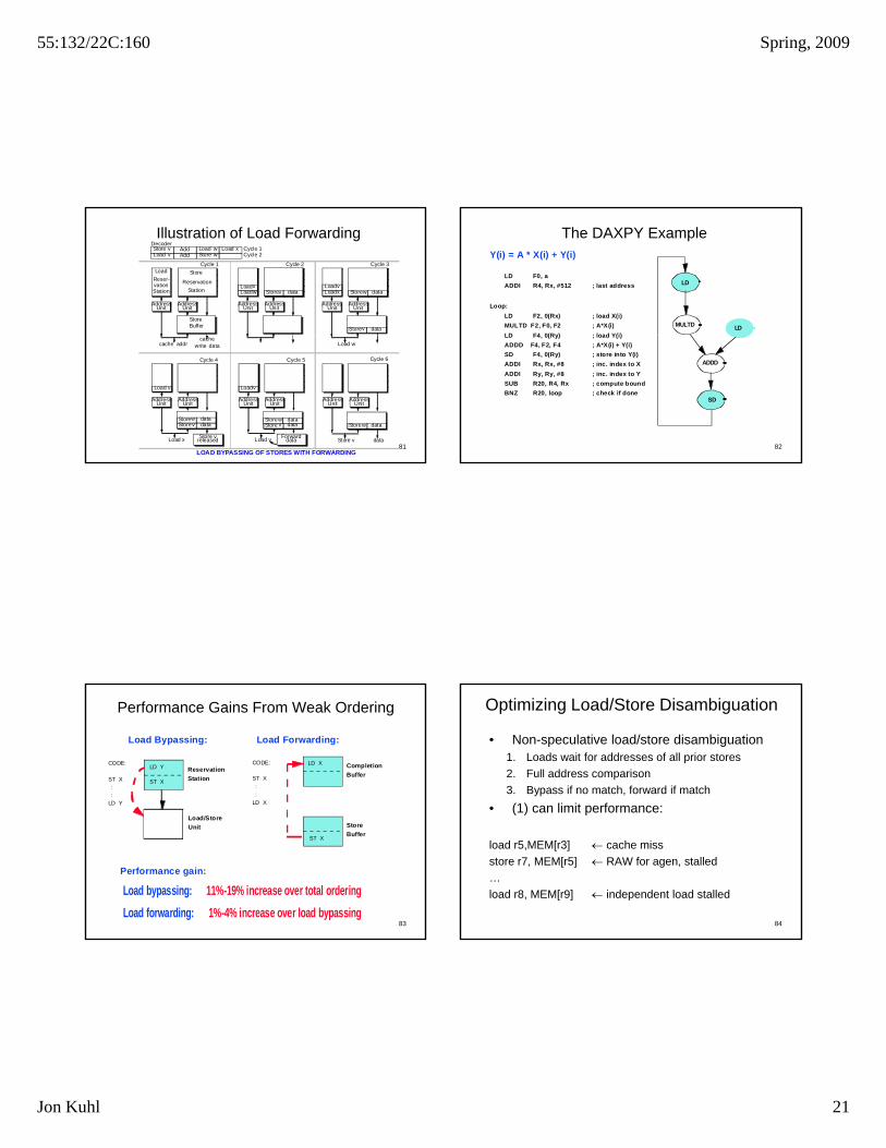
The DAXPY ExampleY(i) = A * X(i) + Y(i)
LD F0, a
ADDI R4, Rx, #512 ; last address
Loop:
LD F2, 0(Rx) ; load X(i)
MULTD F2, F0, F2 ; A*X(i)
LD F4 0(Ry) ; load Y(i)
LD
LDMULTD
82
LD F4, 0(Ry) ; load Y(i)
ADDD F4, F2, F4 ; A*X(i) + Y(i)
SD F4, 0(Ry) ; store into Y(i)
ADDI Rx, Rx, #8 ; inc. index to X
ADDI Ry, Ry, #8 ; inc. index to Y
SUB R20, R4, Rx ; compute bound
BNZ R20, loop ; check if done
ADDD
SD
Performance Gains From Weak Ordering
Load Bypassing: Load Forwarding:
CODE:
ST X
: :
LD Y
CODE:
ST X
:
:
LD X
Reservation
Station
Completion
BufferST X
LD YLD X
83
Performance gain:
Load bypassing: 11%-19% increase over total ordering
Load forwarding: 1%-4% increase over load bypassing
Store
Buffer
Load/Store
Unit
ST X
Optimizing Load/Store Disambiguation
• Non-speculative load/store disambiguation1. Loads wait for addresses of all prior stores
2. Full address comparison
3. Bypass if no match, forward if match
• (1) can limit performance:
84
(1) can limit performance:
load r5,MEM[r3] cache miss
store r7, MEM[r5] RAW for agen, stalled
…
load r8, MEM[r9] independent load stalled

55:132/22C:160 Spring, 2009
Jon Kuhl 22
Speculative Disambiguation
• What if aliases are rare?1. Loads don’t wait for addresses
of all prior stores
2. Full address comparison of stores that are ready
3. Bypass if no match, forward if t h
LoadQueue
StoreQueue
Load/Store RS
Agen
Mem
85
match
4. Check all store addresses when they commit
– No matching loads –speculation was correct
– Matching unbypassed load –incorrect speculation
5. Replay starting from incorrect load
Queue Queue
Reorder Buffer
Use of Prediction
• If aliases are rare: static prediction– Predict no alias every time
• Why even implement forwarding? PowerPC 620 doesn’t
– Pay misprediction penalty rarely• If aliases are more frequent: dynamic prediction
– Use PHT-like history table for loads
86
Use PHT like history table for loads• If alias predicted: delay load• If aliased pair predicted: forward from store to load
– More difficult to predict pair [store sets, Alpha 21264]
– Pay misprediction penalty rarely• Memory cloaking [Moshovos, Sohi]
– Predict load/store pair– Directly copy store data register to load target register– Reduce data transfer latency to absolute minimum
Load/Store Disambiguation Discussion
• RISC ISA:– Many registers, most variables allocated to registers– Aliases are rare– Most important to not delay loads (bypass)– Alias predictor may/may not be necessary
• CISC ISA:– Few registers many operands from memory
87
Few registers, many operands from memory– Aliases much more common, forwarding necessary– Incorrect load speculation should be avoided– If load speculation allowed, predictor probably necessary
• Address translation:– Can’t use virtual address (must use physical)– Wait till after TLB lookup is done– Or, use subset of untranslated bits (page offset)
• Safe for proving inequality (bypassing OK)• Not sufficient for showing equality (forwarding not OK)
The Memory BottleneckDispatch Buffer
Dispatch
RS’s
Branch
Reg. File Ren. Reg.
Reg. Write Back
Integer Integer Float.- Load/ Eff. Addr. Gen.
88
Reorder Buff.
Point Store Addr. Translation
D-cache Access
Data Cache
Complete
Retire
Store Buff.

55:132/22C:160 Spring, 2009
Jon Kuhl 23
Load/Store ProcessingFor both Loads and Stores:
1. Effective Address Generation:
Must wait on register value
Must perform address calculation
2. Address Translation:
Must access TLB
Can potentially induce a page fault (exception)
For Loads: D cache Access (Read)
89
For Loads: D-cache Access (Read)Can potentially induce a D-cache miss
Check aliasing against store buffer for possible load forwarding
If bypassing store, must be flagged as “speculative” load until completion
For Stores: D-cache Access (Write)When completing must check aliasing against “speculative” loads
After completion, wait in store buffer for access to D-cache
Can potentially induce a D-cache miss
Easing The Memory BottleneckDispatch Buffer
Dispatch
RS’s
Branch
Reg. File Ren. Reg.
Reg. Write Back
Integer Integer Float.- Load/ Load/
90
Reorder Buff.
Point Store
Data Cache
Complete
Retire
Store Buff.
Store
Missed loads
Memory Bottleneck TechniquesDynamic Hardware (Microarchitecture):
Use Non-blocking D-cache (need missed-load buffers)
Use Multiple Load/Store Units (need multiported D-cache)
Use More Advanced Caches (victim cache, stream buffer)
Use Hardware Prefetching (need load history and stride detection)
91
Static Software (Code Transformation):
Insert Prefetch or Cache-Touch Instructions (mask miss penalty)
Array Blocking Based on Cache Organization (minimize misses)
Reduce Unnecessary Load/Store Instructions (redundant loads)
Software Controlled Memory Hierarchy (expose it to above DSI)
Advanced Memory Hierarchy
• Better miss rate: victim caches
• Reducing miss costs through software restructuring
• Higher bandwidth: Lock-up free caches, superscalar caches
• Beyond simple blocks
• Two level caches
92
• Prefetching, software prefetching
• Main Memory, DRAM
• Virtual Memory, TLBs
• Interaction of caches, virtual memory

55:132/22C:160 Spring, 2009
Jon Kuhl 24
Jouppi’s Victim Cache
• Targeted at conflict misses
• Victim cache: a small fully associative cache
– holds victims replaced in direct-mapped or low-assoc
– LRU replacement
– a miss in cache + a hit in victim cache
• => move line to main cache
• Poor man’s associativity
93
• Poor man s associativity
– Not all sets suffer conflicts; provide limited capacity for conflicts
Address
Hash0
Jouppi’s Victim Cache
• Removes conflict misses, mostly useful for DM or 2-way
– Even one entry helps some benchmarks
– I-cache helped more than D-cache
• Versus cache size
– Generally, victim cache helps more for smaller caches
• Versus line size
helps more with larger line size (why?)
94
– helps more with larger line size (why?)
• Used in Pentium Pro (P6) I-cache
Address
Hash0
Software Restructuring
• If column-major (Fortran)
– x[i+1, j] follows x [i,j] in memory
– x[i,j+1] long after x[i,j] in memory
• Poor code
for i = 1, rows
for j 1 columns tiguo
us a
ddre
sse
s
95
for j = 1, columns
sum = sum + x[i,j]
• Conversely, if row-major (C/C++)
• Poor code
for j = 1, columns
for i = 1, rows
sum = sum + x[i,j]
Co
nt
Contiguous addresses
Software Restructuring
• Better column-major code
for j = 1, columns
for i = 1, rows
sum = sum + x[i,j]
• Optimizations - need to check if it
tiguo
us a
ddre
sse
s
96
is valid to do them
– Loop interchange (used above)
– Merging arrays
– Loop fusion
– Blocking
Co
nt

55:132/22C:160 Spring, 2009
Jon Kuhl 25
Superscalar Caches
• Increasing issue width => wider caches
• Parallel cache accesses are harder than parallel functional units
• Fundamental difference:
– Caches have state, functional units don’t
97
– Operation thru one port affects future operations thru others
• Several approaches used
– True multi-porting
– Multiple cache copies
– Virtual multi-porting
– Multi-banking (interleaving)
Multiple Cache Copies
Load Port 0
Load Port 1
Store Port
98
• Used in DEC Alpha 21164, IBM Power4
• Independent load paths
• Single shared store path
– May be exclusive with loads, or internally dual-ported
• Bottleneck, not practically scalable beyond 2 paths
• Provides some fault-tolerance
– Parity protection per copy
– Parity error: restore from known-good copy
– Avoids more complex ECC (no RMW for subword writes), still provides SEC
Virtual Multiporting
• Used in IBM Power2 and DEC 21264
– 21264 wave pipelining - pipeline wires WITHOUT latches
Port 0
Port 1
99
21264 wave pipelining pipeline wires WITHOUT latches
• Time-share a single port
• Requires very careful array design to guarantee balanced paths
– Second access cannot catch up with first access
• Probably not scalable beyond 2 ports
• Complicates and reduces benefit of speed binning
Multi-banking or Interleaving
Port 0
Port 1
Bank 0
Cro
ssbar C
ross
bar
Port 0
Port 1
Bank 1
Bank 2
Bank 3
Bank 4
Bank 5
Bank 6
Bank 7
100
• Used in Intel Pentium (8 banks)
• Need routing network
• Must deal with bank conflicts
– Bank conflicts not known till address generated
– Difficult in non-data-capture machine with speculative scheduling
• Replay – looks just like a cache miss
– Sensitive to bank interleave: fine-grained vs. coarse-grained
• Spatial locality: many temporally local references to same block
– Combine these with a “row buffer” approach?

55:132/22C:160 Spring, 2009
Jon Kuhl 26
Combined Schemes
• Multiple banks with multiple ports
• Virtual multiporting of multiple banks
• Multiple ports and virtual multiporting
• Multiple banks with multiply virtually multiported ports
101
p
• Complexity!
• No good solution known at this time
– Current generation superscalars get by with 1-3 ports
Beyond Simple Blocks
• Break blocks into
– Address block associated with tag
– Transfer block to/from memory (subline, sub-block)
• Large address blocks
102
– Decrease tag overhead
– But allow fewer blocks to reside in cache (fixed mapping)
Tag Subline 0 Subline 1 Subline 2 Subline 3
Subline Valid Bits
Tag Subline 0 Subline 1 Subline 2 Subline 3
Tag Subline 0 Subline 1 Subline 2 Subline 3
Tag Subline 0 Subline 1 Subline 2 Subline 3
Beyond Simple Blocks
• Larger transfer block
– Exploit spatial locality
– Amortize memory latency
– But take longer to load
– Replace more data already cached (more conflicts)
– Cause unnecessary traffic
103
• Typically used in large L2/L3 caches to limit tag overhead
• Sublines tracked by MSHR during pending fill
Tag Subline 0 Subline 1 Subline 2 Subline 3
Subline Valid Bits
Tag Subline 0 Subline 1 Subline 2 Subline 3
Tag Subline 0 Subline 1 Subline 2 Subline 3
Tag Subline 0 Subline 1 Subline 2 Subline 3
Latency vs. Bandwidth
• Latency can be handled by
– Hiding (or tolerating) it - out of order issue, nonblocking cache
– Reducing it – better caches
• Parallelism helps to hide latency
104
– MLP – multiple outstanding cache misses overlapped
• But increases bandwidth demand
• Latency ultimately limited by physics

55:132/22C:160 Spring, 2009
Jon Kuhl 27
Latency vs. Bandwidth
• Bandwidth can be handled by “spending” more (hardware cost)
– Wider buses, interfaces
– Banking/interleaving, multiporting
• Ignoring cost, a well-designed system should never be bandwidth-limited
– Can’t ignore cost!
• Bandwidth improvement usually increases latency
105
– No free lunch
• Hierarchies decrease bandwidth demand to lower levels
– Serve as traffic filters: a hit in L1 is filtered from L2
• Parallelism puts more demand on bandwidth
• If average b/w demand is not met => infinite queues
– Bursts are smoothed by queues
• If burst is much larger than average => long queue
– Eventually increases delay to unacceptable levels
Prefetching• Even “demand fetching” prefetches other words in block
– Spatial locality
• Prefetching is useless
– Unless a prefetch costs less than demand miss
• Ideally, prefetches should
– Always get data before it is referenced
106
y g
– Never get data not used
– Never prematurely replace data
– Never interfere with other cache activity
Software Prefetching
• Use compiler to try to
– Prefetch early
– Prefetch accurately
• Prefetch into
– Register (binding)
107
• Use normal loads? ROB fills up, fetch stalls
• What about page faults? Exceptions?
– Caches (non-binding) – preferred
• Needs ISA support
Software Prefetching
• For example:
do j= 1, cols
do ii = 1 to rows by BLOCK
prefetch (&(x[i,j])+BLOCK) # prefetch one block ahead
do i = ii to ii + BLOCK-1
108
sum = sum + x[i,j]
• How many blocks ahead should we prefetch?
– Affects timeliness of prefetches
– Must be scaled based on miss latency

55:132/22C:160 Spring, 2009
Jon Kuhl 28
Hardware Prefetching
• What to prefetch
– One block spatially ahead
– N blocks spatially ahead
– Based on observed stride
• When to prefetch
109
p
– On every reference
• Hard to find if block to be prefetched already in the cache
– On every miss
• Better than doubling block size
– Tagged
• Prefetch when prefetched item is referenced
Prefetching for Pointer-based Data Structures
• What to prefetch
– Next level of tree: n+1, n+2, n+?
• Entire tree? Or just one path
– Next node in linked list: n+1, n+2, n+?
– Jump-pointer prefetching
110
– Markov prefetching
• How to prefetch
– Software places jump pointers in data structure
– Hardware scans blocks for pointers
• Content-driven data prefetching
0xafde 0xfde0
0xde04
Stream or Prefetch Buffers
• Prefetching causes capacity and conflict misses (pollution)
– Can displace useful blocks
• Aimed at compulsory and capacity misses
• Prefetch into buffers, NOT into cache
– On miss start filling stream buffer with successive lines
111
– Check both cache and stream buffer
• Hit in stream buffer => move line into cache (promote)
• Miss in both => clear and refill stream buffer
• Performance
– Very effective for I-caches, less for D-caches
– Multiple buffers to capture multiple streams (better for D-caches)
• Can use with any prefetching scheme to avoid pollution
Multilevel Caches
• Ubiquitous in high-performance processors
– Gap between L1 (core frequency) and main memory too high
– Level 2 usually on chip, level 3 on or off-chip, level 4 off chip
• Inclusion in multilevel caches
112
– Multi-level inclusion holds if L2 cache is superset of L1
– Can handle virtual address synonyms
– Filter coherence traffic: if L2 misses, L1 needn’t see snoop
– Makes L1 writes simpler
• For both write-through and write-back

55:132/22C:160 Spring, 2009
Jon Kuhl 29
Multilevel Inclusion
• Example: local LRU not sufficient to guarantee inclusion
Assume L1 holds two and L2 holds three blocks
P14
234
1,2,1,3,1,4 1,2,3,4
113
– Assume L1 holds two and L2 holds three blocks
– Both use local LRU
• Final state: L1 contains 1, L2 does not
– Inclusion not maintained
• Different block sizes also complicate inclusion
Multilevel Inclusion
• Inclusion takes effort to maintain
– Make L2 cache have bits or pointers giving L1 contents
P14
234
1,2,1,3,1,4 1,2,3,4
114
– Invalidate from L1 before replacing from L2
– In example, removing 1 from L2 also removes it from L1
• Number of pointers per L2 block
– L2 blocksize/L1 blocksize
• Reading list: [Wang, Baer, Levy ISCA 1989]
Multilevel Miss Rates
• Miss rates of lower level caches
– Affected by upper level filtering effect
– LRU becomes LRM, since “use” is “miss”
– Can affect miss rates, though usually not important
• Miss rates reported as:
115
• Miss rates reported as:
– Miss per instruction
– Global miss rate
– Local miss rate
– “Solo” miss rate
• L2 cache sees all references (unfiltered by L1)