instruction bulletin ib no.: 016 jefferson es org november
TRANSCRIPT
IB #016.doc-1
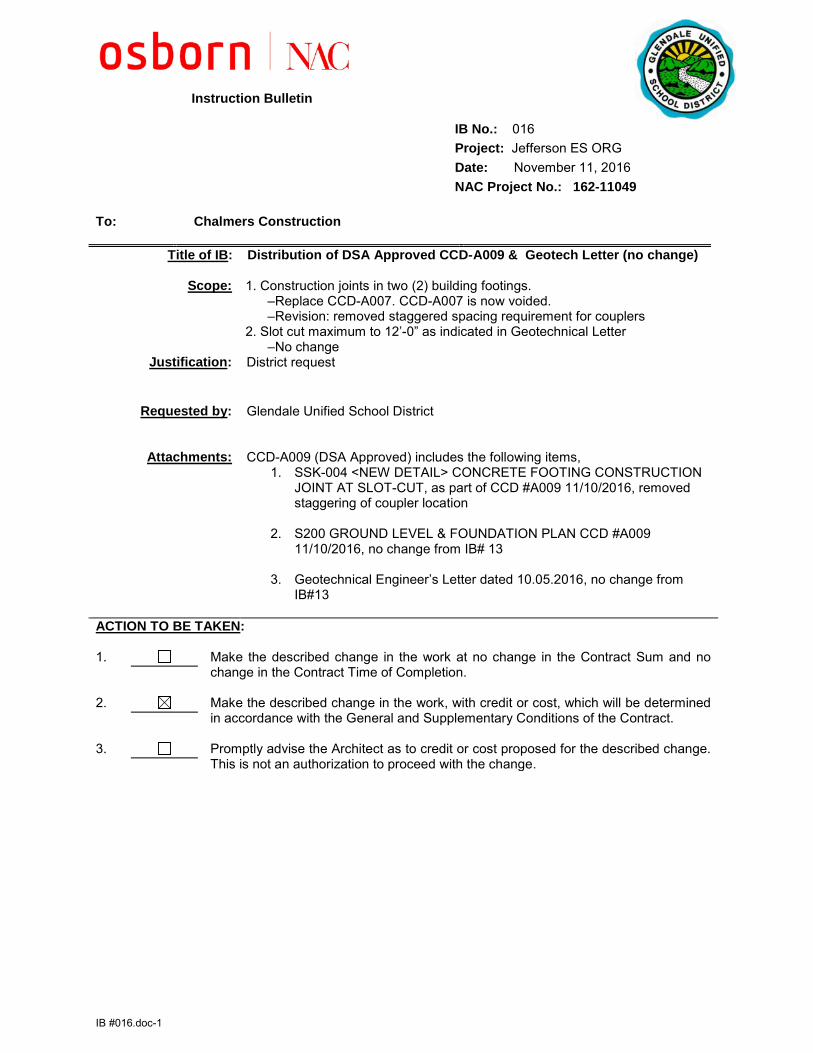
Instruction Bulletin IB No.: 016 Project: Jefferson ES ORG Date: November 11, 2016 NAC Project No.: 162-11049 To: Chalmers Construction
Title of IB: Distribution of DSA Approved CCD-A009 & Geotech Letter (no change)
Scope:
1. Construction joints in two (2) building footings. –Replace CCD-A007. CCD-A007 is now voided. –Revision: removed staggered spacing requirement for couplers 2. Slot cut maximum to 12’-0” as indicated in Geotechnical Letter –No change
Justification: District request
Requested by: Glendale Unified School District
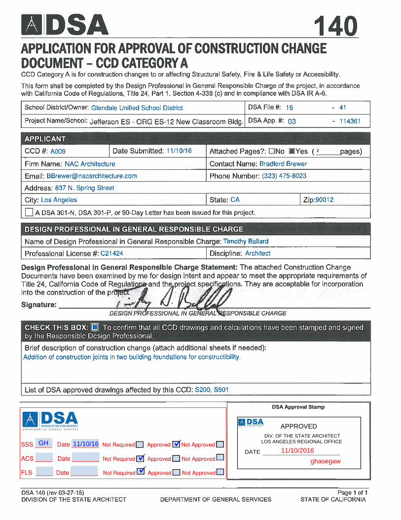
Attachments: CCD-A009 (DSA Approved) includes the following items, 1. SSK-004 <NEW DETAIL> CONCRETE FOOTING CONSTRUCTION
JOINT AT SLOT-CUT, as part of CCD #A009 11/10/2016, removed staggering of coupler location
2. S200 GROUND LEVEL & FOUNDATION PLAN CCD #A009 11/10/2016, no change from IB# 13
3. Geotechnical Engineer’s Letter dated 10.05.2016, no change from IB#13
ACTION TO BE TAKEN: 1. Make the described change in the work at no change in the Contract Sum and no
change in the Contract Time of Completion.
2. Make the described change in the work, with credit or cost, which will be determined in accordance with the General and Supplementary Conditions of the Contract.
3. Promptly advise the Architect as to credit or cost proposed for the described change. This is not an authorization to proceed with the change.
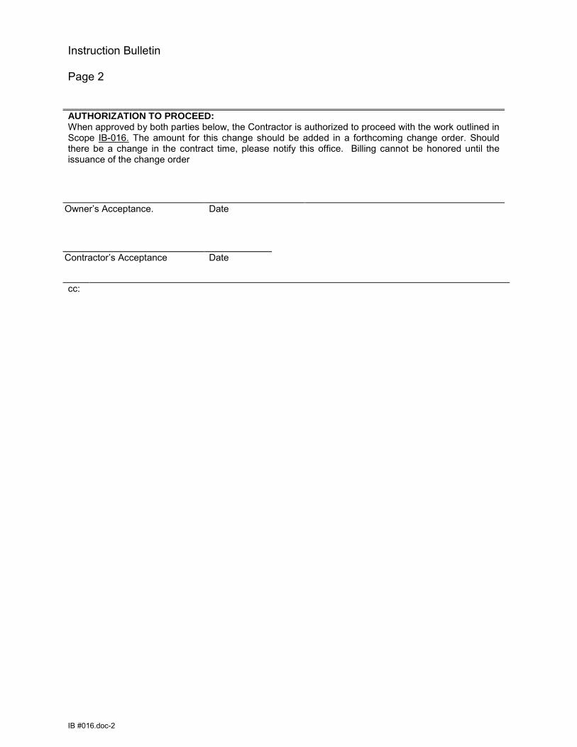
Instruction Bulletin Page 2
IB #016.doc-2
cc:
AUTHORIZATION TO PROCEED: When approved by both parties below, the Contractor is authorized to proceed with the work outlined in Scope IB-016. The amount for this change should be added in a forthcoming change order. Should there be a change in the contract time, please notify this office. Billing cannot be honored until the issuance of the change order
Owner’s Acceptance. Date
Contractor’s Acceptance Date
APPROVED DIV. OF THE STATE ARCHITECT
LOS ANGELES REGIONAL OFFICE
SS FLS AC
DATE
APPROVED DIV. OF THE STATE ARCHITECT
LOS ANGELES REGIONAL OFFICE
ghasegaw
DATE 11/10/2016ü
üü
GH 11/10/16
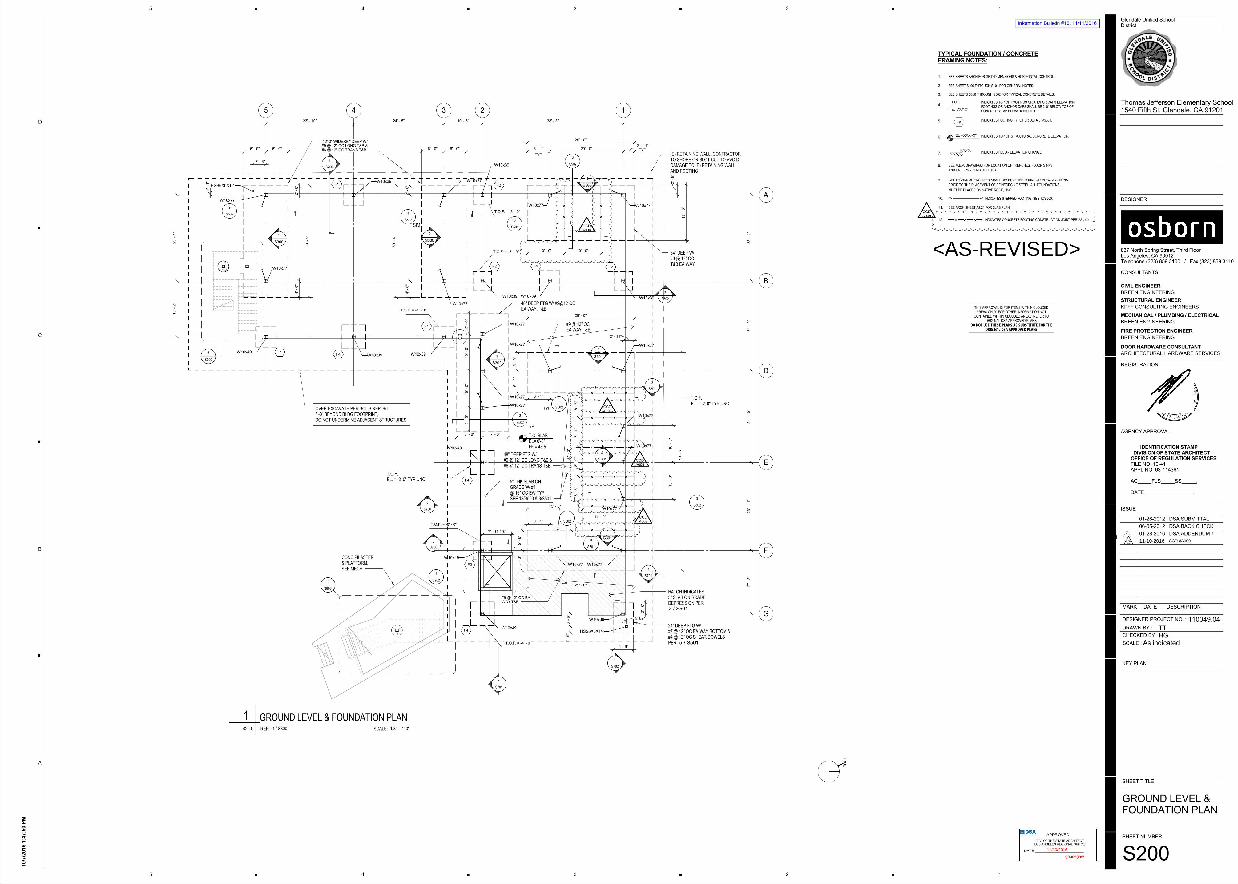
TYPICAL FOUNDATION / CONCRETE
FRAMING NOTES:
T.O.F.
INDICATES FLOOR ELEVATION CHANGE.
9.
7.
6.
4.
3.
2. SEE SHEET S100 THROUGH S101 FOR GENERAL NOTES.
INDICATES TOP OF FOOTINGS OR ANCHOR CAPS ELEVATION.
FOOTINGS OR ANCHOR CAPS SHALL BE 2'-0" BELOW TOP OF
CONCRETE SLAB ELEVATION U.N.O.
INDICATES TOP OF STRUCTURAL CONCRETE ELEVATION.
SEE SHEETS S500 THROUGH S502 FOR TYPICAL CONCRETE DETAILS.
AND UNDERGROUND UTILITIES.
SEE M.E.P. DRAWINGS FOR LOCATION OF TRENCHES, FLOOR SINKS,
PRIOR TO THE PLACEMENT OF REINFORCING STEEL. ALL FOUNDATIONS
GEOTECHNICAL ENGINEER SHALL OBSERVE THE FOUNDATION EXCAVATIONS
INDICATES STEPPED FOOTING, SEE 12/S500.SS10.
5. INDICATES FOOTING TYPE PER DETAIL 5/S501.F#
8.
1. SEE SHEETS ARCH FOR GRID DIMENSIONS & HORIZONTAL CONTROL.
MUST BE PLACED ON NATIVE ROCK, UNO.
EL=XXX'-X"
EL =XXX'-X"
11. SEE ARCH SHEET A2.21 FOR SLAB PLAN.
INDICATES CONCRETE FOOTING CONSTRUCTION JOINT PER 12.
12
A
B
F
G
D
E
345
C
20' - 0"
23' -
4"
24' -
5"
24' -
10"
23' -
11"
17' -
2"
23' - 10" 24' - 5"
23' -
4"
15' -
2"
10' - 6" 38' - 3"
F1
F4
F1
F1
4' -
6"
2' -
6" F2
2' -
6"
4' -
6"
TYP
6' - 1" TYP2' - 11"
F2 F2
TYP
F4
F2
F4
48" DEEP FTG W/#9 @ 12" OC LONG T&B  @ 12" OC TRANS T&B
12'-0" WIDEx36" DEEP W/#9 @ 12" OC LONG T&B  @ 12" OC TRANS T&B
1
S700
2
S700
3
S700
1
S701
2
S701
3
S701
S900
1
S900
3
W10x77
W10x77
W10x49W10x39 W10x39
W10x77
SIM
W10x77W10x39
W10x39
W10x77 W10x77
15' -
0"
54" DEEP W/#9 @ 12" OCT&B EA WAY
3
S502
W10x39 W10x39 W10x39
W10x77 W10x77
2' - 11"
W10x77
W10x77
W10x77
W10x49
W10x49
W10x49
W10x39
W10x77W10x77
W10x77
W10x77
#9 @ 12" OC EAWAY T&B
14' - 0"
(E) RETAINING WALL. CONTRACTORTO SHORE OR SLOT CUT TO AVOIDDAMAGE TO (E) RETAINING WALLAND FOOTING
5" THK SLAB ONGRADE W/ #4@ 16" OC EW TYP.SEE 13/S500 & 3/S501 3
S502W10x77
T.O.F. = -4' - 0"
T.O.F. = -6' - 0"
T.O. SLABEL= 0'-0"FF = 48.5'
S902
1
1
S502
2
S502
1
S502
TYP
2
S502 1
S502
OVER-EXCAVATE PER SOILS REPORT5'-0" BEYOND BLDG FOOTPRINT,DO NOT UNDERMINE ADJACENT STRUCTURES.
48" DEEP FTG W/ #9@12"OCEA WAY, T&B
6' -
6"
10' -
0"
10' -
0"
5' -
6"
6' - 1"
6' - 1"
10' -
0"
10' -
0"
29' - 0"
59' -
3"
29' - 0"
15' - 0"
37' -
3"
29' - 0"
30' -
4"
30' -
4"
F1 #9 @ 12" OCEA WAY T&B
1
S302
1
S300
2
S300
4
S300
3
S301
2
S301
1
S301
3' -
0"
5' - 6"
24" DEEP FTG W/#7 @ 12" OC EA WAY BOTTOM  @ 12" OC SHEAR DOWELSPER
T.O.F.EL. = -2'-0" TYP UNO
T.O.F.EL. = -2'-0" TYP UNO
1
S702
2
S702
HSS6X6X1/4
HSS6X6X1/4
9 1/2"
3' -
6"
3' - 6"
1' -
1"
1' -
9"
7' - 11 1/8"
5' -
6"
5' -
6"
7' - 0" 7' - 0"
6' -
0"
5' -
0"
T.O.F. = -4' - 0"
6' - 0" 6' - 0"6' - 0" 6' - 0"
T.O.F. = -3' - 0"
T.O.F. = -3' - 0"
2' -
8"
HATCH INDICATES3" SLAB ON GRADEDEPRESSION PER
/2 S501
/5 S501
CONC PILASTER& PLATFORM.SEE MECH
10' - 0" 10' - 0"
6' -
"
8' -
"
8' -
0"
8' -
"
8
S501
8
S501
IDENTIFICATION STAMP
DIVISION OF STATE ARCHITECT
OFFICE OF REGULATION SERVICES
FILE NO. 19-41APPL NO. 03-114361
AC FLS SS .
DATE .
837 North Spring Street, Third FloorLos Angeles, CA 90012Telephone (323) 859 3100 / Fax (323) 859 3110
KPFF CONSULTING ENGINEERS
CIVIL ENGINEER
BREEN ENGINEERING
CONSULTANTS
DESIGNER
MECHANICAL / PLUMBING / ELECTRICAL
ENGINEERBREEN ENGINEERING
DOOR HARDWARE CONSULTANT
ARCHITECTURAL HARDWARE SERVICES
REGISTRATION
AGENCY APPROVAL
ISSUE
12345
D
C
B
A
MARK DATE DESCRIPTION
KEY PLAN
SCALE :
CHECKED BY :
DRAWN BY :
DESIGNER PROJECT NO. :
Glendale Unified SchoolDistrict
SHEET TITLE
SHEET NUMBER
STRUCTURAL ENGINEER
12345
FIRE PROTECTION ENGINEER
BREEN ENGINEERING
01-26-2012 DSA SUBMITTAL
TTHG
06-05-2012 DSA BACK CHECK
01-28-2016 DSA ADDENDUM 11
As indicated
10/7
/2016 1
:47:5
0 P
M
S200
GROUND LEVEL &FOUNDATION PLAN
110049.04
Thomas Jefferson Elementary School1540 Fifth St. Glendale, CA 91201
TR
UE
SCALE:REF: 1/8" = 1'-0"S200 1 / S300
1 GROUND LEVEL & FOUNDATION PLAN
1
<AS-REVISED>
SSK004.
THIS APPROVAL IS FOR ITEMS WITHIN CLOUDEDAREAS ONLY. FOR OTHER INFORMATION NOT
CONTAINED WITHIN CLOUDED AREAS, REFER TOORIGINAL DSA APPROVED PLANS.
DO NOT USE THESE PLANS AS SUBSTITUTE FOR THEORIGINAL DSA APPROVED PLANS
81
3
11-10-2016 CCD #009CCDA009
CCD #A009
CCDA009
CCDA009
CCDA009
CCDA009
CCDA009
APPROVED DIV. OF THE STATE ARCHITECT
LOS ANGELES REGIONAL OFFICE
SS FLS AC
DATE
APPROVED DIV. OF THE STATE ARCHITECT
LOS ANGELES REGIONAL OFFICE
ghasegaw
DATE 11/10/2016
Information Bulletin #16, 11/11/2016
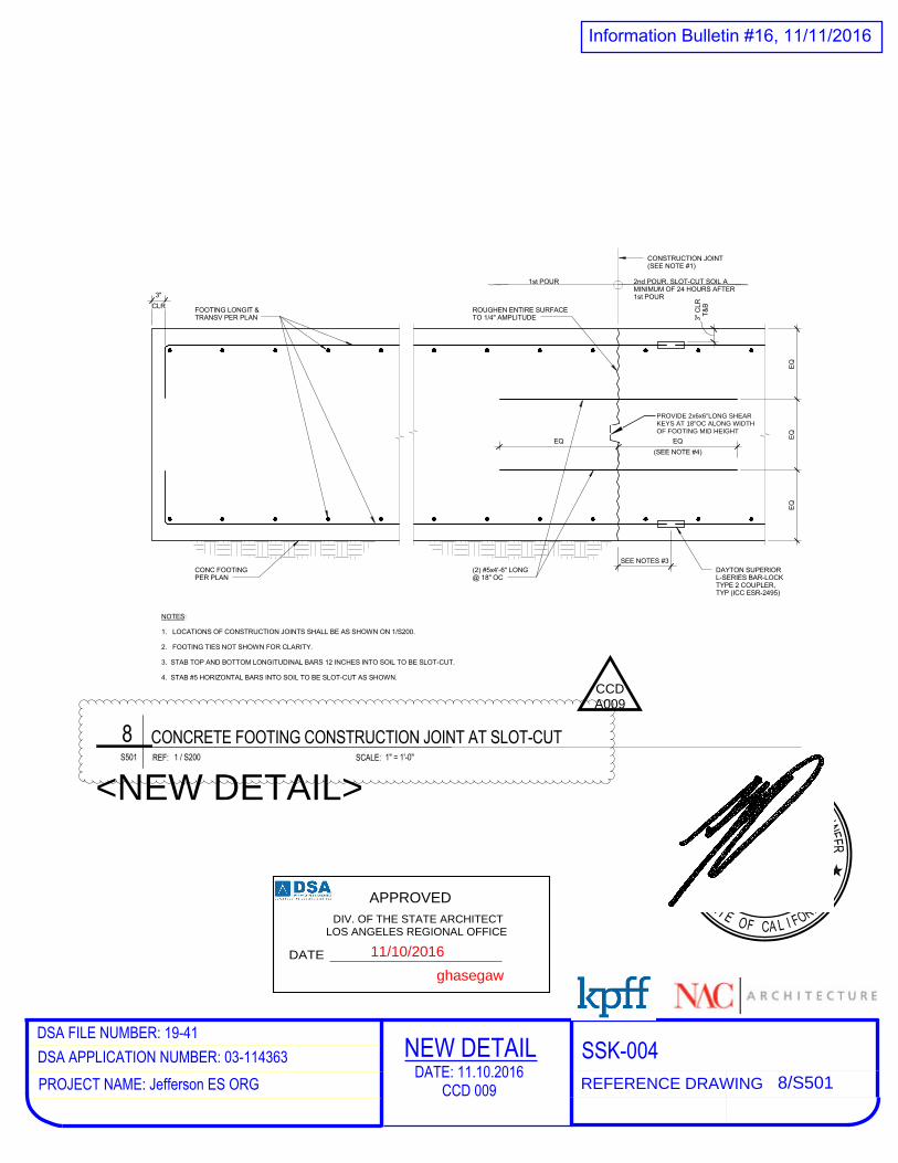
CLR
3"
SEE NOTES #3
EQ
EQ
EQ
EQ
(SEE NOTE #4)
EQ
DAYTON SUPERIORL-SERIES BAR-LOCKTYPE 2 COUPLER,TYP (ICC ESR-2495)
T&
B3"
CLR
(2) #5x4'-6" LONG@ 18" OC
1st POUR 2nd POUR. SLOT-CUT SOIL AMINIMUM OF 24 HOURS AFTER1st POUR
CONSTRUCTION JOINT(SEE NOTE #1)
ROUGHEN ENTIRE SURFACETO 1/4" AMPLITUDE
CONC FOOTINGPER PLAN
FOOTING LONGIT &TRANSV PER PLAN
NOTES:
1. LOCATIONS OF CONSTRUCTION JOINTS SHALL BE AS SHOWN ON 1/S200.
2. FOOTING TIES NOT SHOWN FOR CLARITY.
3. STAB TOP AND BOTTOM LONGITUDINAL BARS 12 INCHES INTO SOIL TO BE SLOT-CUT.
4. STAB #5 HORIZONTAL BARS INTO SOIL TO BE SLOT-CUT AS SHOWN.
SCALE:REF: 1" = 1'-0"S501 1 / S200
8 CONCRETE FOOTING CONSTRUCTION JOINT AT SLOT-CUT
DSA FILE NUMBER: 1941DSA APPLICATION NUMBER: 03114363PROJECT NAME: Jefferson ES ORG
SSK004REFERENCE DRAWING 8/S501
NEW DETAILDATE: 11.10.2016
CCD 009
<NEW DETAIL>
PROVIDE 2x6x6"LONG SHEARKEYS AT 18"OC ALONG WIDTHOF FOOTING MID HEIGHT
CCDA009
APPROVED DIV. OF THE STATE ARCHITECT
LOS ANGELES REGIONAL OFFICE
SS FLS AC
DATE
APPROVED DIV. OF THE STATE ARCHITECT
LOS ANGELES REGIONAL OFFICE
ghasegaw
DATE 11/10/2016
Information Bulletin #16, 11/11/2016
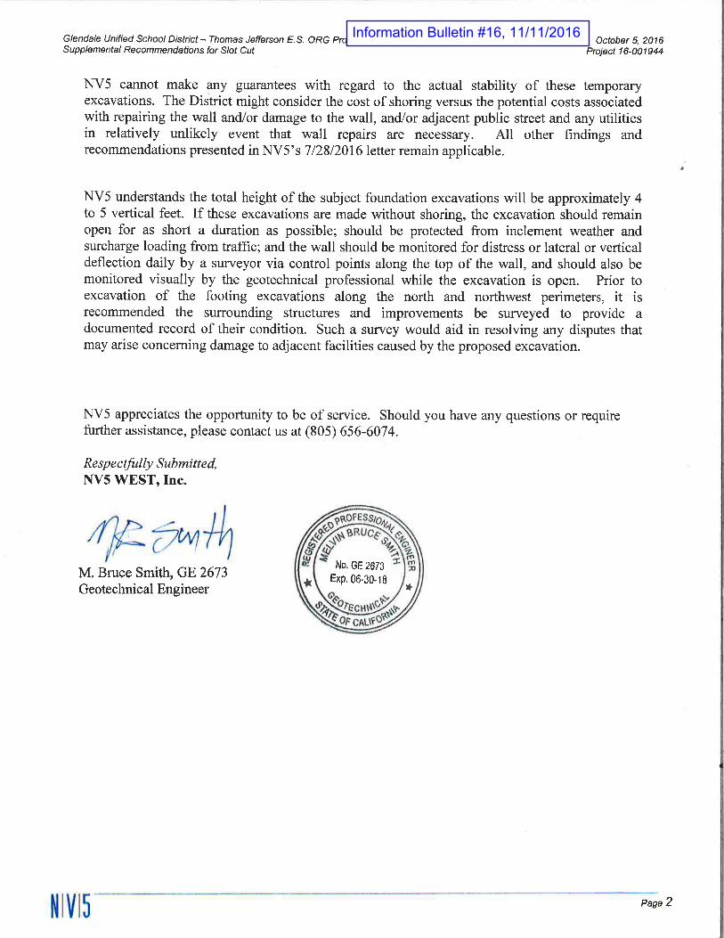
1868 PALMA DRIVE, SUITE A VENTURA, CA 93003 WWW.NV5.COM OFFICE 805.656.6074 FAX 805.650.6264
CONSTRUCTION QUALITY ASSURANCE - INFRASTRUCTURE - ENERGY - PROGRAM MANAGEMENT - ENVIRONMENTAL
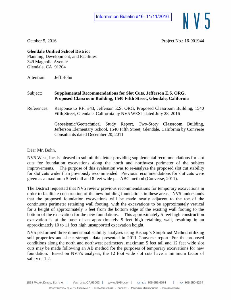
October 5, 2016 Project No.: 16-001944
Glendale Unified School District
Planning, Development, and Facilities
349 Magnolia Avenue
Glendale, CA 91204
Attention: Jeff Bohn
Subject: Supplemental Recommendations for Slot Cuts, Jefferson E.S. ORG,
Proposed Classroom Building, 1540 Fifth Street, Glendale, California
References: Response to RFI #43, Jefferson E.S. ORG, Proposed Classroom Building, 1540
Fifth Street, Glendale, California by NV5 WEST dated July 28, 2016
Geoseismic/Geotechnical Study Report, Two-Story Classroom Building,
Jefferson Elementary School, 1540 Fifth Street, Glendale, California by Converse
Consultants dated December 20, 2011
Dear Mr. Bohn,
NV5 West, Inc. is pleased to submit this letter providing supplemental recommendations for slot
cuts for foundation excavations along the north and northwest perimeter of the subject
improvements. The purpose of this evaluation was to re-analyze the proposed slot cut stability
for slot cuts wider than previously recommended. Previous recommendations for slot cuts were
given as a maximum 5 feet tall and 8 feet wide per ABC method (Converse, 2011).
The District requested that NV5 review previous recommendations for temporary excavations in
order to facilitate construction of the new building foundations in these areas. NV5 understands
that the proposed foundation excavations will be made nearly adjacent to the toe of the
continuous perimeter retaining wall footing, with the excavations to be approximately vertical
for a height of approximately 5 feet from the bottom edge of the existing wall footing to the
bottom of the excavation for the new foundations. This approximately 5 feet high construction
excavation is at the base of an approximately 5 feet high retaining wall, resulting in an
approximately 10 to 11 feet high unsupported excavation height.
NV5 performed three dimensional stability analyses using Bishop’s Simplified Method utilizing
soil properties and shear strength data presented in 2011 Converse report. For the proposed
conditions along the north and northwest perimeters, maximum 5 feet tall and 12 feet wide slot
cuts may be made following an AB method for the purposes of temporary excavations for new
foundation. Based on NV5’s analyses, the 12 foot wide slot cuts have a minimum factor of
safety of 1.2.
Information Bulletin #16, 11/11/2016
Information Bulletin #16, 11/11/2016