instruction bulletin february 2002 - …igate.alamedaelectric.com/modicon documents/powerlogic...
TRANSCRIPT

Instruction Bulletin63230-400-204/A1
February 2002
POWERLOGIC® Circuit Monitor Series 3000Installation Manual
Retain for future use
© 2002 Schneider Electric All Rights Reserved
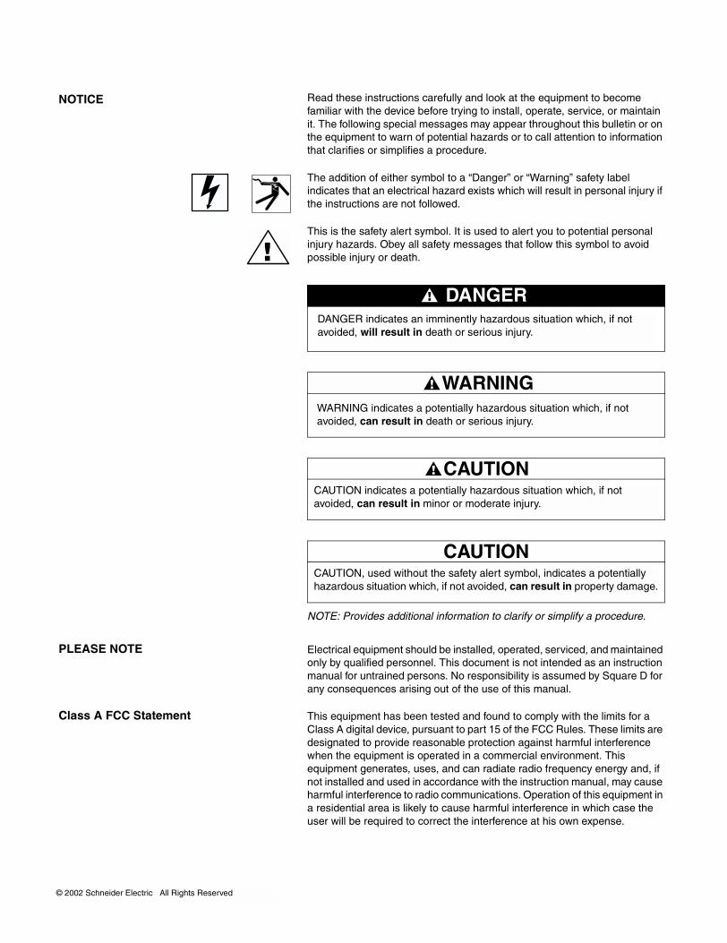
Read these instructions carefully and look at the equipment to become familiar with the device before trying to install, operate, service, or maintain it. The following special messages may appear throughout this bulletin or on the equipment to warn of potential hazards or to call attention to information that clarifies or simplifies a procedure.
The addition of either symbol to a “Danger” or “Warning” safety label indicates that an electrical hazard exists which will result in personal injury if the instructions are not followed.
This is the safety alert symbol. It is used to alert you to potential personal injury hazards. Obey all safety messages that follow this symbol to avoid possible injury or death.
NOTE: Provides additional information to clarify or simplify a procedure.
Electrical equipment should be installed, operated, serviced, and maintained only by qualified personnel. This document is not intended as an instruction manual for untrained persons. No responsibility is assumed by Square D for any consequences arising out of the use of this manual.
This equipment has been tested and found to comply with the limits for a Class A digital device, pursuant to part 15 of the FCC Rules. These limits are designated to provide reasonable protection against harmful interference when the equipment is operated in a commercial environment. This equipment generates, uses, and can radiate radio frequency energy and, if not installed and used in accordance with the instruction manual, may cause harmful interference to radio communications. Operation of this equipment in a residential area is likely to cause harmful interference in which case the user will be required to correct the interference at his own expense.
NOTICE
DANGER indicates an imminently hazardous situation which, if not avoided, will result in death or serious injury.
DANGER
WARNINGWARNING indicates a potentially hazardous situation which, if not avoided, can result in death or serious injury.
CAUTIONCAUTION indicates a potentially hazardous situation which, if not avoided, can result in minor or moderate injury.
CAUTIONCAUTION, used without the safety alert symbol, indicates a potentially hazardous situation which, if not avoided, can result in property damage.
PLEASE NOTE
Class A FCC Statement

63230-400-204/A1 POWERLOGIC® Circuit Monitor Series 3000 Installation ManualFebruary 2002 Contents
© 2002 SSchneider Electric All Rights Reserved
CONTENTS
NOTICE . . . . . . . . . . . . . . . . . . . . . . . . . . . . . . . . . . . . . . . . . . . . . . . . . . . 2PLEASE NOTE . . . . . . . . . . . . . . . . . . . . . . . . . . . . . . . . . . . . . . . . . . . . . . 2
CLASS A FCC STATEMENT . . . . . . . . . . . . . . . . . . . . . . . . . . . . . . . . . . . 2
CHAPTER 1—INTRODUCTION . . . . . . . . . . . . . . . . . . . . . . . . . . . . . . . . 1
CHAPTER CONTENTS . . . . . . . . . . . . . . . . . . . . . . . . . . . . . . . . . . . . . . . 1
WHAT IS THE CIRCUIT MONITOR? . . . . . . . . . . . . . . . . . . . . . . . . . . . . . 2Accessories and Options for the Circuit Monitor . . . . . . . . . . . . . . . . . 3Features . . . . . . . . . . . . . . . . . . . . . . . . . . . . . . . . . . . . . . . . . . . . . . . . 3
TOPICS NOT COVERED IN THIS BULLETIN . . . . . . . . . . . . . . . . . . . . . . 4
FIRMWARE . . . . . . . . . . . . . . . . . . . . . . . . . . . . . . . . . . . . . . . . . . . . . . . . 4
CHAPTER 2—SAFETY PRECAUTIONS . . . . . . . . . . . . . . . . . . . . . . . . . . 5
CHAPTER 3—GETTING STARTED . . . . . . . . . . . . . . . . . . . . . . . . . . . . . 7
CHAPTER CONTENTS . . . . . . . . . . . . . . . . . . . . . . . . . . . . . . . . . . . . . . . 7
SETTING UP THE CIRCUIT MONITOR: QUICK START . . . . . . . . . . . . . 8
FACTORY DEFAULTS . . . . . . . . . . . . . . . . . . . . . . . . . . . . . . . . . . . . . . . . 9
IMPORTANT PROCEDURES FOR SMS USERS . . . . . . . . . . . . . . . . . . 10
CHAPTER 4—INSTALLATION . . . . . . . . . . . . . . . . . . . . . . . . . . . . . . . . 11
CHAPTER CONTENTS . . . . . . . . . . . . . . . . . . . . . . . . . . . . . . . . . . . . . . 11
CIRCUIT MONITOR INSTALLATION . . . . . . . . . . . . . . . . . . . . . . . . . . . . 12
Dimensions . . . . . . . . . . . . . . . . . . . . . . . . . . . . . . . . . . . . . . . . . . . . 14Mounting . . . . . . . . . . . . . . . . . . . . . . . . . . . . . . . . . . . . . . . . . . . . . . 15
Mounting Considerations . . . . . . . . . . . . . . . . . . . . . . . . . . . . . . 15Mounting Procedure . . . . . . . . . . . . . . . . . . . . . . . . . . . . . . . . . . 16
DISPLAY INSTALLATION . . . . . . . . . . . . . . . . . . . . . . . . . . . . . . . . . . . . 18Description . . . . . . . . . . . . . . . . . . . . . . . . . . . . . . . . . . . . . . . . . . . . . 18Dimensions . . . . . . . . . . . . . . . . . . . . . . . . . . . . . . . . . . . . . . . . . . . . 20Mounting . . . . . . . . . . . . . . . . . . . . . . . . . . . . . . . . . . . . . . . . . . . . . . 20
Mounting Considerations . . . . . . . . . . . . . . . . . . . . . . . . . . . . . . 20Mounting Procedure . . . . . . . . . . . . . . . . . . . . . . . . . . . . . . . . . . 21
Connecting the Display . . . . . . . . . . . . . . . . . . . . . . . . . . . . . . . . . . . 22RJ-12 Display Cable Pinout . . . . . . . . . . . . . . . . . . . . . . . . . . . . 23
OPTION CARDS . . . . . . . . . . . . . . . . . . . . . . . . . . . . . . . . . . . . . . . . . . . . 24
ACTIVATING REVENUE SECURITY . . . . . . . . . . . . . . . . . . . . . . . . . . . . 25Enabling the Security Button . . . . . . . . . . . . . . . . . . . . . . . . . . . . . . . 25Activating/Deactivating Revenue Security . . . . . . . . . . . . . . . . . . . . . 26
CHAPTER 5—WIRING . . . . . . . . . . . . . . . . . . . . . . . . . . . . . . . . . . . . . . . 29
CHAPTER CONTENTS . . . . . . . . . . . . . . . . . . . . . . . . . . . . . . . . . . . . . . 29
REQUIREMENTS BEFORE YOU BEGIN WIRING . . . . . . . . . . . . . . . . . 30Control Power . . . . . . . . . . . . . . . . . . . . . . . . . . . . . . . . . . . . . . . . . . 30
Control Power Transformers . . . . . . . . . . . . . . . . . . . . . . . . . . . 30Control Power Fusing . . . . . . . . . . . . . . . . . . . . . . . . . . . . . . . . . 31
i
POWERLOGIC® Circuit Monitor Series 3000 Installation Manual 63230-400-204/A1Contents February 2002
ii
Potential (Voltage) Transformers . . . . . . . . . . . . . . . . . . . . . . . . 31
Required Protection for CE Compliance . . . . . . . . . . . . . . . . . . . . . . 32
WIRING CTS, PTS, AND CONTROL POWER TO THE CIRCUIT MONITOR 33
Making the Connections . . . . . . . . . . . . . . . . . . . . . . . . . . . . . . . . . . 34
WIRING DIAGRAMS . . . . . . . . . . . . . . . . . . . . . . . . . . . . . . . . . . . . . . . . . 35Wiring Multiple Circuit Monitors to a Single Set of PTs and CPTs . . . 46Deriving Control Power from Phase PT Inputs . . . . . . . . . . . . . . . . . 47
GROUNDING THE CIRCUIT MONITOR . . . . . . . . . . . . . . . . . . . . . . . . . 49
WIRING THE SOLID-STATE KYZ OUTPUT . . . . . . . . . . . . . . . . . . . . . . 50
WIRING ERROR DETECTION . . . . . . . . . . . . . . . . . . . . . . . . . . . . . . . . . 51
Running the Diagnostics Wiring Error Test . . . . . . . . . . . . . . . . . . . . 51
CHAPTER 6—COMMUNICATIONS CONNECTIONS . . . . . . . . . . . . . . . 55
CHAPTER CONTENTS . . . . . . . . . . . . . . . . . . . . . . . . . . . . . . . . . . . . . . 55
COMMUNICATIONS CAPABILITIES . . . . . . . . . . . . . . . . . . . . . . . . . . . . 56Protocols . . . . . . . . . . . . . . . . . . . . . . . . . . . . . . . . . . . . . . . . . . . . . . 56
CONNECTING TO A HOST USING THE RS-485 PORT . . . . . . . . . . . . . 57Connecting to a Host Using the Optical Communications Interface (OCIVF) . . . . . . . . . . . . . . . . . . . . . . . . . . . . . . . . . . . . . . . . . . . . . . .58
DAISY-CHAINING DEVICES TO THE CIRCUIT MONITOR . . . . . . . . . . 58
Connecting the First Device on the Daisy Chain . . . . . . . . . . . . . . . . 61Length of the Communications Link . . . . . . . . . . . . . . . . . . . . . . . . . . 62Terminating the Communications Link . . . . . . . . . . . . . . . . . . . . . . . . 62
Using the MCTAS-485 Terminator . . . . . . . . . . . . . . . . . . . . . . . 63Using the MCT-485 Terminator . . . . . . . . . . . . . . . . . . . . . . . . . 64
WIRING FOR 2-WIRE MODBUS OR JBUS COMMUNICATION . . . . . . . . . . . . . . . . . . . . . . . . . . . . . . . . .65
Terminating 2-Wire MODBUS or JBUS Communications . . . . . . . . . 66
CONNECTING TO A POWERLOGIC ETHERNET GATEWAY (EGX) . . . 67
CONNECTING TO A POWERLOGIC ETHERNET COMMUNICATION CARD (ECC21) . . . . . . . . . . . . . . . . . . . . . . . . . . . . . . . . . . . . . . . . . . . . . 68
CHAPTER 7—MINIMUM SETUP . . . . . . . . . . . . . . . . . . . . . . . . . . . . . . . 69
CHAPTER CONTENTS . . . . . . . . . . . . . . . . . . . . . . . . . . . . . . . . . . . . . . 69
OPERATING THE DISPLAY . . . . . . . . . . . . . . . . . . . . . . . . . . . . . . . . . . . 70How the Buttons Work . . . . . . . . . . . . . . . . . . . . . . . . . . . . . . . . . . . .70Display Menu Conventions . . . . . . . . . . . . . . . . . . . . . . . . . . . . . . . . 71
Selecting a Menu Option . . . . . . . . . . . . . . . . . . . . . . . . . . . . . .71Changing a Value . . . . . . . . . . . . . . . . . . . . . . . . . . . . . . . . . . . .71
MAIN MENU OVERVIEW . . . . . . . . . . . . . . . . . . . . . . . . . . . . . . . . . . . . . 72
CONFIGURING THE CIRCUIT MONITOR USING THE SETUP MENU . 73Setting Up the Display . . . . . . . . . . . . . . . . . . . . . . . . . . . . . . . . . . . .73Setting Up the Communications . . . . . . . . . . . . . . . . . . . . . . . . . . . . 74
Setting the Device Address . . . . . . . . . . . . . . . . . . . . . . . . . . . . 74
RS-485 and Infrared Port Communications Setup . . . . . . . . . . .75
© 2002 Schneider Electric All Rights Reserved
63230-400-204/A1 POWERLOGIC® Circuit Monitor Series 3000 Installation ManualFebruary 2002 Contents
© 2002 SSchneider Electric All Rights Reserved
Ethernet Communications Card (ECC) Setup . . . . . . . . . . . . . . 76
Setting Up the Metering Functions of the Circuit Monitor . . . . . . . . . 76
CHAPTER 8—TROUBLESHOOTING . . . . . . . . . . . . . . . . . . . . . . . . . . . 79
CHAPTER CONTENTS . . . . . . . . . . . . . . . . . . . . . . . . . . . . . . . . . . . . . . 79
GETTING TECHNICAL SUPPORT . . . . . . . . . . . . . . . . . . . . . . . . . . . . . 81
TROUBLESHOOTING . . . . . . . . . . . . . . . . . . . . . . . . . . . . . . . . . . . . . . . 82
GLOSSARY . . . . . . . . . . . . . . . . . . . . . . . . . . . . . . . . . . . . . . . . . . . . . . . 91
INDEX . . . . . . . . . . . . . . . . . . . . . . . . . . . . . . . . . . . . . . . . . . . . . . . . . . . . 95
iii

POWERLOGIC® Circuit Monitor Series 3000 Installation Manual 63230-400-204/A1Contents February 2002
iv
© 2002 Schneider Electric All Rights Reserved
63230-400-204/A1 Chapter 1—IntroductionFebruary 2002 Chapter Contents
© 2002 Schneider Electric All Rights Reserved
CHAPTER 1—INTRODUCTION
CHAPTER CONTENTS
CHAPTER CONTENTS . . . . . . . . . . . . . . . . . . . . . . . . . . . . . . . . . . . . . . . 1WHAT IS THE CIRCUIT MONITOR? . . . . . . . . . . . . . . . . . . . . . . . . . . . . . 2Accessories and Options for the Circuit Monitor . . . . . . . . . . . . . . . . . 3Features . . . . . . . . . . . . . . . . . . . . . . . . . . . . . . . . . . . . . . . . . . . . . . . . 3
TOPICS NOT COVERED IN THIS BULLETIN . . . . . . . . . . . . . . . . . . . . . . 4
FIRMWARE . . . . . . . . . . . . . . . . . . . . . . . . . . . . . . . . . . . . . . . . . . . . . . . . 4
This chapter offers a general description of the Series 3000 Circuit Monitor, tells how to best use this bulletin, and lists related documents.
1

Chapter 1—Introduction 63230-400-204/A1What is the Circuit Monitor? February 2002
2
WHAT IS THE CIRCUIT MONITOR?
Table 1–1: Summary of C
Real-Time R
• Current (per phase, N, G, 3-P• Voltage (L–L, L–N, 3-Phase)• Real Power (per phase, 3-Ph• Reactive Power (per phase, 3• Apparent Power (per phase, • Power Factor (per phase, 3-P• Frequency• Temperature (internal ambien• THD (current and voltage)• K-Factor (per phase)
Demand Re
• Demand Current (per phase • Demand Voltage (per phase • Average Power Factor (3-Pha• Demand Real Power (per ph• Demand Reactive Power (pe• Demand Apparent Power (pe• Coincident Readings • Predicted Power Demands
The circuit monitor is a multifunction, digital instrumentation, data acquisition and control device. It can replace a variety of meters, transducers, and other components. The circuit monitor can be located at the service entrance to monitor the cost and quality of power, and can be used to evaluate the utility service. When located at equipment mains, the circuit monitor can detect voltage-based disturbances that cause costly equipment downtime.
The circuit monitor is equipped with RS-485 communication for integration into any power monitoring and control system. However, System Manager™ software (SMS) from POWERLOGIC, which is written specifically for power monitoring and control, best supports the circuit monitor’s advanced features.
The circuit monitor is a true rms meter capable of exceptionally accurate measurement of highly nonlinear loads. A sophisticated sampling technique enables accurate, true rms measurement through the 63rd harmonic. You can view over 50 metered values plus extensive minimum and maximum data from the display or remotely using software. Table 1–1 summarizes the readings available from the circuit monitor.
ircuit Monitor Instrumentation
eadings Energy Readings
hase)
ase)-Phase)
3-Phase)hase)
t)
• Accumulated Energy, Real• Accumulated Energy, Reactive• Accumulated Energy, Apparent • Bidirectional Readings • Reactive Energy by Quadrant• Incremental Energy• Conditional Energy
adings Power Analysis Values
present, 3-Phase avg.)present, 3-Phase avg.) se total)
ase present, peak)r phase present, peak)r phase present, peak)
• Crest Factor (per phase)• Displacement Power Factor (per phase, 3-Phase)• Fundamental Voltages (per phase)• Fundamental Currents (per phase)• Fundamental Real Power (per phase)• Fundamental Reactive Power (per phase)• Harmonic Power• Unbalance (current and voltage)• Phase Rotation• Harmonic Magnitudes & Angles (per phase)• Sequence Components
© 2002 Schneider Electric All Rights Reserved

63230-400-204/A1 Chapter 1—IntroductionFebruary 2002 What is the Circuit Monitor?
© 2002 Schneider Electric All Rights Reserved
Table 1–2: Circuit Monitor
Description
Circuit Monitor
VFD Display with infrared (IR) po
LCD Display
Optical Communications Interfac
Digital I /O CardField installable with 4 digital inpu1 pulse output (KYZ)
Ethernet Communications Card w100 Mbps fiber or 10/100 Mbps U
CM3 Mounting Adapter
CM3 L Adapter Plate
4-ft display cable (1.2 m)
12-ft display cable (3.6 m)
30-ft display cable (9.1 m)
10-ft RS-232 cable (3 m)
➀ For parts list of individual input
Accessories and Options for the Circuit Monitor
Features
The circuit monitor has a modular design to maximize its usability. In addition to the main meter, the circuit monitor has plug-on modules and accessories, including:
• Remote display. The optional remote 4-line display is available with a back-lit liquid crystal display (LCD) or a vacuum fluorescent display (VFD). The VFD model includes an infrared port that can be used to communicate directly with the circuit monitor from a laptop and can be used to download firmware, which keeps the circuit monitor up to date with the latest system enhancements.
• Digital I /O Card. You can further expand the I/O capabilities of the circuit monitor by adding a digital I/O card (4 inputs and 4 outputs). This card fits into the option slot on the top of the circuit monitor.
• Ethernet Communications Card. The Ethernet communications card provides an Ethernet port that accepts a 100 Mbps fiber optic cable or a10/100 Mbps UTP and provides an RS-485 master port to extend the circuit monitor communications options. This card is easily installed into the option slot on the top of the circuit monitor.
Table 1–2 lists the circuit monitor parts and accessories and their associated instruction bulletins.
Some of the circuit monitor’s many features include:
• True rms metering to the 63rd harmonic
• Accepts standard CT and PT inputs
• 600 volt direct connection on metering inputs
• ANSI C12.20 0.5 class revenue accuracy
• IEC 60687 0.5S class revenue accuracy
Parts, Accessories, and Custom Cables
Part Number Document Number
CM3250CM3250MG
63230-300-200
CM3350CM3350MG
63230-301-200
rt and proximity sensor CMDVF63230-305-200
CMDLC
e (for use with the VFD display only) OCIVF 63230-306-200
ts (120 Vac), 3 (10 A) relay outputs (120Vac), IOC44 63230-303-200
ith TP Ethernet port and 1 RS-485 master port
ECC21 63230-304-200
CM3MA63230-204-31663230-400-212
CM3LA 63230-400-211
CAB-4
N/ACAB-12
CAB-30
CAB-106
s and outputs, see the circuit monitor reference manual 63230-400-204.
3

Chapter 1—Introduction 63230-400-204/A1Topics Not Covered in This Bulletin February 2002
4
TOPICS NOT COVERED IN THIS BULLETIN
FIRMWARE
• Min/max readings of metered data
• Power quality readings—THD, K-factor, crest factor
• Real-time harmonic magnitudes and angles to the 63rd harmonic
• Current and voltage sag/swell detection and recording (CM3350)
• Downloadable firmware
• Easy setup through the optional remote display (password protected) where you can view metered values
• Setpoint-controlled alarm and relay functions
• Onboard alarm and data logging
• Wide operating temperature range –25° to 70°C
• Modular, field-installable digital modules
• Flexible communications—RS-485 communication is standard, optional Ethernet communications card available with fiber optic connection
• One option card slot for field-installable I/O or Ethernet capabilities
• Standard 8MB onboard logging memory• CT and PT wiring diagnostics• Revenue security with utility sealing capability
Some of the circuit monitor’s advanced features, such as onboard data logs and alarm log files, can only be set up over the communications link using SMS. SMS versions 3.3 and higher support the CM3000 device type.This circuit monitor instruction bulletin describes these advanced features, but does not tell how to set them up. For instructions on using SMS, refer to the SMS online help and the SMS-3000 Setup Guide, which is available in English, French, and Spanish. For information about related instruction bulletins, see Table 1–2 on page 3.
This instruction bulletin is written to be used with firmware version 12.200 or higher. See the reference manual (63230-400-207) for instructions on how to determine the firmware version.
© 2002 Schneider Electric All Rights Reserved

63230-400-204/A1 Chapter 2—Safety PrecautionsFebruary 2002
© 2002 Schneider Electric All Rights Reserved
CHAPTER 2—SAFETY PRECAUTIO
This chapter contains important safety precautions that must be followed before attempting to install, service, or maintain electrical equipment. Carefully read and follow the safety precautions outlined below.
NS
HAZARD OF ELECTRIC SHOCK, BURN, OR EXPLOSION
• Only qualified workers should install this equipment. Such work should be performed only after reading this entire set of instructions.
• NEVER work alone.
• Turn off all power supplying this equipment before working on or inside.
• Always use a properly rated voltage sensing device to confirm that all power is off.
• Before performing visual inspections, tests, or maintenance on this equipment, disconnect all sources of electric power. Assume that all circuits are live until they have been completely de-energized, tested, and tagged. Pay particular attention to the design of the power system. Consider all sources of power, including the possibility of backfeeding.
• Beware of potential hazards, wear personal protective equipment, carefully inspect the work area for tools and objects that may have been left inside the equipment.
• Use caution while removing or installing panels so that they do not extend into the energized bus; avoid handling the panels, which could cause personal injury.
• The successful operation of this equipment depends upon proper handling, installation, and operation. Neglecting fundamental installation requirements may lead to personal injury as well as damage to electrical equipment or other property.
• Before performing Dielectric (Hi-Pot) or Megger testing on any equipment in which the circuit monitor is installed, disconnect all input and output wires to the circuit monitor. High voltage testing may damage electronic components contained in the circuit monitor.
Failure to follow these instructions will result in death or serious injury.
DANGER
5

Chapter 2—Safety Precautions 63230-400-204/A1February 2002
6
© 2002 Schneider Electric All Rights Reserved
63230-400-204/A1 Chapter 3—Getting StartedFebruary 2002 Chapter Contents
© 2002 Schneider Electric All Rights Reserved
CHAPTER 3—GETTING STARTED
CHAPTER CONTENTS
CHAPTER CONTENTS . . . . . . . . . . . . . . . . . . . . . . . . . . . . . . . . . . . . . . . 7SETTING UP THE CIRCUIT MONITOR: QUICK START . . . . . . . . . . . . . 8
FACTORY DEFAULTS . . . . . . . . . . . . . . . . . . . . . . . . . . . . . . . . . . . . . . . . 9
IMPORTANT PROCEDURES FOR SMS USERS . . . . . . . . . . . . . . . . . . 10
Read this chapter to get a quick overview about what it takes to get your circuit monitor installed and operating.
7

Chapter 3—Getting Started 63230-400-204/A1Setting Up the Circuit Monitor: Quick Start February 2002
8
SETTING UP THE CIRCUIT MONITOR: QUICK START
HAZARD OF ELECTRIC SHOCK, BURN, OR EXPLOSION
• Turn off all power supplying the circuit monitor and the equipment in which it is installed before working on it.
• Use a properly rated voltage testing device to verify that the power is off.
• Never short the secondary of a PT.
• Never open circuit a CT; use the shorting block to short circuit the leads of the CT before removing the connection from the circuit monitor.
Failure to follow this instruction will result in death or serious injury.
DANGER
The circuit monitor is shipped with factory default settings that give you the option to use the circuit monitor “right out of the box,” or you can customize it to suit your needs. At minimum, you must to do the following installation and setup steps to get the circuit monitor to meter properly:
1. Mount the hardware.See Chapter 4—Installation on page 11.
a. Install any accessories. (See the instructions that ship with each accessory for installation instructions.)
b. Mount the circuit monitor.
c. Mount the display (if present).
2. Wire the components.See Chapter 5—Wiring on page 29.
a. Wire the circuit monitor.b. Wire any inputs and outputs. (See the instructions that ship with the
I/Os for wiring instructions.)c. Wire the communications.
3. Set up communications and the meter.At minimum, you must set up these parameters:• CT primary and secondary
• PT primary and secondary• System type• Frequency
• Address, baud rate, and parity for the selected communications port• Set the IP address for the ECC.
If you are using SMS, do the following:
a. From the display, set up the address, baud rate, and parity. See “Setting Up the Communications” on page 74 for instructions.
b. Use SMS to configure the circuit monitor and set up the minimum parameters listed above. See “Working with Devices” in the SMS online help for instructions. You can also set up alarms, logs, and I/Os, but these are not required for minimum setup.
If you are NOT using SMS, do the following:Use the display to configure the circuit monitor. From the main menu, select Setup > Meter to display the Meter Setup menu. See “Setting Up the Metering Functions of the Circuit Monitor” on page 76 for details.
4. Initiate a wiring error test from the circuit monitor display.See “Wiring Error Detection” on page 51 for instructions.
5. Initialize the meter. Meter initialization resets energy, demand, files, trending, min/max and disables all alarms.
If you are using SMS:
a. Select Control > Resets.b. From the Reset Device Data screen, select the device. From the
Resets Available, select Meter Initialization.
© 2002 Schneider Electric All Rights Reserved

63230-400-204/A1 Chapter 3—Getting StartedFebruary 2002 Factory Defaults
© 2002 Schneider Electric All Rights Reserved
FACTORY DEFAULTS
c. Click Reset. Click Help on this screen for detailed instructions.
If you are using the display:
a. Select Resets > Meter Init and enter the setup password.b. Read the two information screens. At the Perform Reset prompt, select
Yes.
The circuit monitor is preconfigured with the following features enabled:
• On-board alarm Log will record the last 100 events.
• On-board memory is allocated for one steady-state waveform, eight disturbance waveforms, and twelve 100ms rms event recordings (CM3350 only).
• Data Log 1 will record every 15 minutes the values for the quantities listed in Table 3– 1, retaining the information for the previous seven days.
• Data Log 2 will automatically log at the end of each incremental energy interval, interval-by-interval energy values for the previous 31 days for the parameters listed in Table 3– 2.
Table 3– 1: Quantities logged in Data Log 1
Parameter Values
Current A, B, C, N, G, Average
Voltage L–L A–B, B–C, C–A, Average
Voltage L–N A–N, B–N, C–N, Average
Voltage Unbalance L-N, WorstL-L, Worst
Real Power A,B,C, 3-Phase total
Reactive Power A,B,C, 3-Phase total
Apparent Power A,B,C, 3-Phase total
True Power Factor A,B,C, 3-Phase total
Displacement Power Factor A,B,C, 3-Phase total
Demand Current A, B, C, N, Average
Power Demand kWd, kVARd, kVAd
THD Current A, B, C, N, G
THD Voltage L–N A–N, B–N, C–N
THD Voltage L–L A-B, B-C, C-A
Energy kWhr, kVAhr, kVARhr
Conditional Energy Real In, Real Out, Reactive In, Reactive Out
Table 3– 2: Energy and demand parameters logged in Data Log 2
Parameter Values
Incremental Energy kWh In, kWh Out, kVAh
Peak Real Power Demand over last incremental energy period
kW
Peak Apparent Power Demand over last incremental energy period
kVA
9

Chapter 3—Getting Started 63230-400-204/A1Important Procedures for SMS Users February 2002
10
Table 3–4: Enabled on-board alarmsAlarm Alarm No. Pickup P
Voltage Sag (CM3350 only)
Disturbance 8 to 10
87% (%relative)
Over THD Voltage Standard 39 to 44 50%
Voltage Unbalance Standard 23 to 24 20%
End of Incremental Energy Interval
Digital 1 N/A
IMPORTANT PROCEDURES FOR SMS USERS
• Data Log 3 will automatically perform a fast rolling log of instantaneous data once every minute, retaining the information for the previous 12 hours. The logged values are listed in Table 3– 3.
• Data Log 4 also performs a fast rolling log of the quantities listed in Table 3– 3, but logs them every 5 seconds and retains the information for the previous hour.
• The on-board alarms listed in Table 3–4 have also been enabled.
• Incremental energy is configured for an hourly interval starting at midnight.
If you are using SMS and would like to take advantage of the factory configurations, you must do the following in SMS from the PC after the circuit monitors are installed:
• Set up a scheduled task to automatically upload onboard data logs.
• To ensure the POWERLOGIC software recognizes the preconfigured onboard alarms, you must place your system online and display the Setup Device dialog (click Setup > Devices/Routing > Configure). The software synchronizes the alarm configuration with the system database. Once the two are synchronized, SMS will annunciate any alarms that occur after this point.
For more information, see the SMS online help file.
Table 3– 3: Instantaneous rms data logged in Data Log 3
Parameter Values
Current A, B, C, N, G, Average
Voltage L-L A-B, B-C, C-A, Average
Voltage L-N A–N, B–N, C–N, Average
Real Power 3-Phase total
Reactive Power 3-Phase total
Apparent Power 3-Phase total
True Power Factor 3-Phase total
Displacement Power Factor 3-Phase total
THD Current A, B, C, N, G
THD Voltage L-N A–N, B–N, C–N
THD Voltage L-L A-B, B-C, C-A
ickup delay Dropout Dropout Delay Priority Action
2 cycles90%
(% relative)4 cycles Low
Disturbance WFC, 100ms Event
300 seconds 50% 300 seconds Low Disturbance WFC
300 seconds 20% 300 seconds LowDisturbance WFC,
100 ms Event (CM3350 only)
N/A N/A N/A None Forces Data Log 2 Entry
© 2002 Schneider Electric All Rights Reserved

63230-400-204/A1 Chapter 4—InstallationFebruary 2002 Chapter Contents
© 2002 Schneider Electric All Rights Reserved
CHAPTER 4—INSTALLATION
CHAPTER CONTENTS
CHAPTER CONTENTS . . . . . . . . . . . . . . . . . . . . . . . . . . . . . . . . . . . . . . 11CIRCUIT MONITOR INSTALLATION . . . . . . . . . . . . . . . . . . . . . . . . . . . . 12
Dimensions . . . . . . . . . . . . . . . . . . . . . . . . . . . . . . . . . . . . . . . . . . . . 14Mounting . . . . . . . . . . . . . . . . . . . . . . . . . . . . . . . . . . . . . . . . . . . . . . 15
Mounting Considerations . . . . . . . . . . . . . . . . . . . . . . . . . . . . . . 15
Mounting Procedure . . . . . . . . . . . . . . . . . . . . . . . . . . . . . . . . . . 16
DISPLAY INSTALLATION . . . . . . . . . . . . . . . . . . . . . . . . . . . . . . . . . . . . 18
Description . . . . . . . . . . . . . . . . . . . . . . . . . . . . . . . . . . . . . . . . . . . . . 18Dimensions . . . . . . . . . . . . . . . . . . . . . . . . . . . . . . . . . . . . . . . . . . . . 20Mounting . . . . . . . . . . . . . . . . . . . . . . . . . . . . . . . . . . . . . . . . . . . . . . 20
Mounting Considerations . . . . . . . . . . . . . . . . . . . . . . . . . . . . . . 20Mounting Procedure . . . . . . . . . . . . . . . . . . . . . . . . . . . . . . . . . . 21
Connecting the Display . . . . . . . . . . . . . . . . . . . . . . . . . . . . . . . . . . . 22
RJ-12 Display Cable Pinout . . . . . . . . . . . . . . . . . . . . . . . . . . . . 23
OPTION CARDS . . . . . . . . . . . . . . . . . . . . . . . . . . . . . . . . . . . . . . . . . . . . 24
ACTIVATING REVENUE SECURITY . . . . . . . . . . . . . . . . . . . . . . . . . . . . 25Enabling the Security Button . . . . . . . . . . . . . . . . . . . . . . . . . . . . . . . 25
Activating/Deactivating Revenue Security . . . . . . . . . . . . . . . . . . . . . 26
This chapter describes the parts of the circuit monitor and its accessories and explains how to install the circuit monitor and display. It also describes how to activate revenue security.
NOTE: For wiring instructions, see Chapter 5—Wiring on page 29. To make the communications connections, see Chapter 6—Communications Connections on page 55.
11

Chapter 4—Installation 63230-400-204/A1Circuit Monitor Installation February 2002
12
CIRCUIT MONITOR INSTALLATION
5 6
7
This section describes the circuit monitor hardware, provides dimensional drawings, and explains how to mount the circuit monitor.
Figure 4–1 shows the parts of the circuit monitor. A brief description of each part follows in Table 4–1 on page 13.
Figure 4–1: Parts of the Series 3000 Circuit Monitor
1
2
4
3
9
8
10
© 2002 Schneider Electric All Rights Reserved

63230-400-204/A1 Chapter 4—InstallationFebruary 2002 Circuit Monitor Installation
© 2002 Schneider Electric All Rights Reserved
Table 4–1: Parts of the Circuit Monitor
No. Part
1 Voltage inputs Voltage metering con
2 KYZ KYZ pulse output.
3 RJ-12 display comms port The RJ-12 port is use
4RS-485 port (COM1) with transmit and receive LED indicators
The RS-485 port is uLEDs. The yellow LEcommunications; the
5 Power LED indicator ✦ A steady-state green
6 Maintenance LED indicator ✦ This LED illuminates
7 Access doorThe access door provmetering data in the c
8 Control power supply connector Connection for contro
9 Option card slotOptional cards fit in thup to 10 A) or an Eth
10 Current inputs Current metering con
✦ See Table 8–1 on page 83 in the maintenance chapter for more
Description
nections.
d for communications and control power connections to the remote display.
sed for communications with daisy-chained devices. The port has two corresponding D illuminates when the circuit monitor is receiving data (RX) across the RS-485 green illuminates when data is being transmitted (TX).
LED is continuously illuminated when the circuit monitor is powered up.
red if the circuit monitor is experiencing an internal problem and requires service.
ides access to a security switch that, when activated, locks setup information and ircuit monitor. See “Activating Revenue Security” on page 25 for details.
l power to the circuit monitor.
e slot provided on the top of the circuit monitor, such as a digital I/O card (outputs rated ernet communications card.
nections.
about the LEDs on the circuit monitor.
13
Chapter 4—Installation 63230-400-204/A1Circuit Monitor Installation February 2002
14
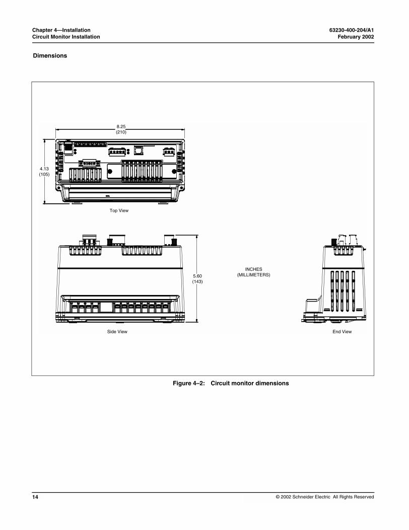
Dimensions
Side View
Top View
8.25(210)
4.13(105)
Figure 4–2: Circuit monitor dimensions
End View
INCHES(MILLIMETERS)5.60
(143)
© 2002 Schneider Electric All Rights Reserved

63230-400-204/A1 Chapter 4—InstallationFebruary 2002 Circuit Monitor Installation
© 2002 Schneider Electric All Rights Reserved
Mounting
Mounting Considerations
Current/Voltage Inputs
Top Vents
Option Card Slot
Vertical Mountin(recommended
Flat Mountin
Before mounting the circuit monitor, understand all mounting considerations described in the following section.
Recommended mounting orientations are shown in Figure 4–3. When choosing a mounting location, consider the following points:
• Allow for easy access to all parts of the circuit monitor. Allow extra space for all wires, fuse disconnects, shorting blocks, accessories, or other components. Make sure to route the wires so that they do not cover the option card slot, or cooling vents on the circuit monitor. Refer to Figure 4–4 on page 17 for required clearances.
• For European Community (CE) compliance, see “Required Protection for CE Compliance” on page 32.
Figure 4–3: Possible ways to orient the circuit monitor
End VentsMount control power towards the top
End Vents
g )
Horizontal Mounting
Horizontal Mounting Invertedg
15

Chapter 4—Installation 63230-400-204/A1Circuit Monitor Installation February 2002
16
Mounting Procedure
• Locate the circuit monitor in an area where ambient conditions fall within the acceptable range. The circuit monitor’s ambient temperature range is -20°C to +70°C when mounted vertically with or without one option card installed. See Table 4– 2 for operating temperatures.
To mount the circuit monitor, follow these instructions:
NOTE: The mounting bracket is not included with the Merlin Gerin circuit monitor.
1. Determine a location for the circuit monitor, making sure you understand all mounting considerations discussed in “Mounting Considerations” on page 15. Also refer to Figure 4–4 on page 17 for dimensions and clearances.
2. Tape the mounting template, included in the circuit monitor shipping carton, to the selected location. Refer to Figure 4–4 on page 17.
Table 4– 2: Operating temperatures
Mounting Orientation Number of Options CardsAmbient Temperature
Rating ➀
Vertical 0 or 1
-20°C to +70°CHorizontal 0
Flat 0
Horizontal 1-20°C to +65°C
Flat 1
➀ Ambient temperature refers to the immediate environment of the circuit monitor, including the temperature within the enclosure in which it is mounted.
IMPROPER VENTILATION
• Do not mount the circuit monitor to a ceiling or in vertical orientations other than the one indicated in this instruction bulletin.
• Provide the clearances around the circuit monitor as illustrated in Figure 4–4 on page 17.
Failure to follow these instructions can result in equipment damage.
CAUTION
DANGERHAZARD OF ELECTRIC SHOCK, BURN, OR EXPLOSION
• Only qualified workers should install and wire the circuit monitor. Perform this work only after completely reading the installation and wiring chapters.
• Turn off all power supplying the circuit monitor and the equipment in which it is installed before working on it.
• Always use a properly rated voltage sensing device to confirm that all power is off.
Failure to follow these instructions will result in death or serious injury.
© 2002 Schneider Electric All Rights Reserved

63230-400-204/A1 Chapter 4—InstallationFebruary 2002 Circuit Monitor Installation
© 2002 Schneider Electric All Rights Reserved
2.41(61.1)
3.59(91.3)
5.27(134)
2.13(54.1)
5.13(130.3)
10.25(260.5)
1.20(30.6)
9.05(230)
8.13(206.5)
0.75(19)
Template and Mounting Bracket Di
0.75(19)
0.39(10)
5.27(134)
0.5(12.5)
Figure 4–4: Dimensions and clearances
1.00(25)
1.13(28.7)
0.5(12.5)
2.40(61)
5.27(134)
10.25(260.5)
DIN Rail Mounting
mensions
Template
Mounting Bracket
CM3000
DIN Rail
6.00(152)
1.00(25)
0.39(10)1.18
(30)
10.25(260.5)
1.00(25)
INCHES(MILLIMETERS)
17

Chapter 4—Installation 63230-400-204/A1Display Installation February 2002
18
DISPLAY INSTALLATION
Description
3. Making sure wires or equipment on the other side of the enclosure will not be damaged, drill three 0.147 in (3.75 mm) diameter mounting holes in locations marked on the template. Remove the template.
4. Attach the mounting bracket with three thread-forming screws (not provided). Use screw size 0.25 inch max., #10 min. (5 mm min., 6 mm max.) Torque the screws 6–9 lb-in (0.68–1 N•m).
5. Attach the CM3000 as shown in Figure 4–5.
Figure 4–5: Attaching the CM3000 to the Mounting Bracket
To mount the CM3000 on a DIN rail, follow these steps:
1. Refer to Figure 4–4 on page 17 for dimensions and clearances.
2. Place the CM3000 so that the slot in the base rests on one edge of the DIN rail and snap it into place securely.
This section describes the display, provides dimensional drawings, and explains how to mount it. Operating the circuit monitor from the display is described in Chapter 7—Minimum Setup on page 69.
The display is an optional accessory used to operate the circuit monitor directly, without using software. The display can be connected to only one circuit monitor at a time. You can permanently mount it with an individual circuit monitor, or you can carry it around to each circuit monitor and plug in as needed. The display includes a viewing area to display information, a red alarm LED, four buttons used to enter and select information, and a contrast button. Table 4–3 describes the parts of the display. Two display models are available:
• LCD display (see Figure 4–6)
• VFD display has an additional proximity sensor and infrared port (see Figure 4–6)
© 2002 Schneider Electric All Rights Reserved

63230-400-204/A1 Chapter 4—InstallationFebruary 2002 Display Installation
© 2002 Schneider Electric All Rights Reserved
Table 4–3: Parts of the Display
Component
➀ Alarm LED Red flashing light illuminates w
➁ Arrow buttons Press the arrow buttons to scro
➂ Enter button Press to select information.
➃ Contrast button Press to change the light and d
➄ Display screen
Use the 4-line LCD or VFD dispinformation, and active alarm dproximity sensor or press a buttmodel is back lit. To activate ba
➅ Menu button Press to go back one menu lev
➆ Infrared port For use with the optical commu
➇ Proximity sensor Detects when you are approac
➅
➁➂
➀
➄
LCD Display
Figure 4–6: LCD and VFD Displays
Description
hen an alarm is active.
ll through and view the options or values displayed on a menu.
ark contrast of the display.
lay to view information such as metered quantities, setup parameters, diagnostic escriptions. The display illuminates on the VFD model when you cross the path of the on on it. Both displays can be set to stay lit for a specified number of minutes. The LCD cklighting, press any button on the display.
el.
nications interface (OCIVF) and a laptop (VFD display only).
hing and turns on the display and buttons (VFD display only).
➃
➅
➁➂
➃➀
➄ ➆ ➇
VFD Display
19

Chapter 4—Installation 63230-400-204/A1Display Installation February 2002
20
Dimensions
Mounting
Mounting Considerations
Figure 4–7: Display dimensions
Before mounting the display, read the following mounting considerations.
When choosing a mounting location, consider these points:
• Allow for easy access to the front and back of the display.
• Be sure that ambient conditions fall within the acceptable range as listed in Appendix A—Specifications on page 85.
• To meet the NEMA 12 rating, you must install a gasket between the display and the mounting surface.
• Mount the display in a horizontal, upright position (as illustrated in the top view in Figure 4–7).
• Use the four mounting screws (M3.5 x 10mm Phillips pan-head threaded screws) provided in the display hardware kit (no. 63230-305-22). If using screws other than those provided, the screws can be no longer than 0.31 in. (6.35 mm) plus the panel thickness. For example, if the panel is 0.09 in. thick, the screw is to be a maximum of 0.31 + 0.09 = 0.40 in. (7.8 + 2.2 = 10 mm).
Typical locations for mounting the display are listed in Table 4–4.
Table 4–4: Typical display mounting locations
Equipment Type Mounting Location
QED Switchboards Disconnect door
POWER-ZONE® IV Switchgear Main instrument compartment door
HVL and VIS/VAC Switchgear Instrument door
Metal-clad and Substation Circuit Breakers Standard relaying locations
ISO-FLEX® Medium Voltage Motor Control Center
Low voltage door
Model 6 Motor Control Center Main meter location or auxiliary section
8.00(203.2)
3.17(80.6)
1.57(39.9)
INCHES(MILLIMETERS)
Top View
Side View
© 2002 Schneider Electric All Rights Reserved

63230-400-204/A1 Chapter 4—InstallationFebruary 2002 Display Installation
© 2002 Schneider Electric All Rights Reserved
Mounting Procedure
Follow these steps to mount the display:1. Before drilling the holes, understand all mounting considerations and verify that the selected location has the required clearances.
2. Tape the template provided in the display hardware kit (no. 63230-305-22) to the selected location on the front of the panelboard. Refer to Figure 4–8 on page 22.
3. Making sure wires or equipment on the inside of the enclosure will not be damaged, drill four 0.16 in. (4 mm) diameter mounting holes in location “A” marked on the template.
4. On the right end of the template, drill or punch one hole that is 0.75 in. minimum to 1.25 in. maximum (19–31.75 mm) diameter through the panel. Remove the template. Smooth the edges of the hole to remove any sharp edges.
NOTE: If this is a NEMA 12 or IP 54 installation, position a gasket between the back of the display and the mounting surface.
HAZARD OF ELECTRIC SHOCK, BURN, OR EXPLOSION
• Only qualified workers should install and wire the circuit monitor. Perform this work only after completely reading this entire instruction bulletin.
• Turn off all power supplying the equipment in which the display is being installed before working on it.
• Always use a properly rated voltage sensing device to confirm that all power is off.
• Do not use mounting screws longer than 0.31 in. (7.8 mm) plus the panel thickness to avoid damage to the internal circuit boards of the display.
Failure to follow this instruction will result in death or serious injury.
DANGER
21

Chapter 4—Installation 63230-400-204/A1Display Installation February 2002
22
1.59(40.30)
3.18(80.60)
2.50(63.50)
5.0(126.7
1.59(40.30)
4.00(101.60)
INCHES(MILLIMETERS)
Connecting the Display
Figure 4–8: Display mounting hole dimensions and locations
5. Position the display against the front of the panel and align the mounting holes in the panel with the mounting holes on the back of the display.
6. Secure the display. Insert the four M3.5 x 10mm screws (kit no. 63230-305-22) through the back of the panel and screw into the mounting holes of the display. Torque the screws 6–9 lb-in (0.68–1 N•m).
The display connects to the RJ12 port on the back of the display and the top of the circuit monitor. The display obtains its control power and communications through the cable. A 12-ft (3.7 m) cable is provided, but 4-ft (1.2 m) and 30-ft (9.1 m) cables are also available (part no. CAB-4 or CAB-30). Plug one end of the cable into the back of the display and the other end into the port labeled with the display icon on the top of circuit monitor as shown in Figure 4–9 on page 23.
1.50(38.10)
3.00(76.20)
2.50(63.50)
1.07(27.05)
2.14(54.10)
00)
8.00(203.20)
4.00(101.60)
3.00(76.50)
1.07(27.05)
A
A A
0.19 (4 Places)4.75
Location A
0.75 Min.19.00
1.25 Max.31.75
© 2002 Schneider Electric All Rights Reserved

63230-400-204/A1 Chapter 4—InstallationFebruary 2002 Display Installation
© 2002 Schneider Electric All Rights Reserved
RJ-12 Display Cable Pinout
Figure 4–9: Display connection to the circuit monitor
The pinout for the display cable and cable requirements are shown in Figure 4–10.
Figure 4–10: RJ-12 display cable pinout
RJ-12 Connection
+12 V GND 11
— — 22
TX RX 33
RX TX 44
— — 55
GND +12 V 66
50 ft (15 m) max. cable length RJ-12 6-position connector 4-wire, 26 AWG (0.1288 mm2) cable
RJ-12 Display Cable
23

Chapter 4—Installation 63230-400-204/A1Option Cards February 2002
24
OPTION CARDS
Option cards fit into the accessory slot on the top of the circuit monitor. Two cards are available, a digital I/O card (with relay outputs rated up to 10 A) and an Ethernet communications card (ECC) for high-speed Ethernet communications. Figure 4–11 shows the location of the accessory slot in the circuit monitor.NOTE: Refer to document no. 63230-304-200 for Ethernet Communications Card (ECC21) installation instructions. For the digital I/O card (part no. IOC44) installation instructions, see document no. 63230-303-200.
Figure 4–11: Location of vented slot for optional accessory cards
Accessory slot with vented covers
© 2002 Schneider Electric All Rights Reserved

63230-400-204/A1 Chapter 4—InstallationFebruary 2002 Activating Revenue Security
© 2002 Schneider Electric All Rights Reserved
ACTIVATING REVENUE SECURITY
Enabling the Security Button
The access door, shown in Figure 4–12 on page 26, lets you access the revenue metering security switch. When you press this button, it locks set up of the circuit monitor so that the revenue-related setup parameters of the circuit monitor cannot be changed from the display or over the communications link. In addition, you can attach a standard lead/wire seal to secure the door closed and to visually detect any tampering with the meter. The following information is locked when revenue security is active:
• Metering configuration• CT ratios (primary and secondary)
• PT ratios (primary and secondary)• All scale factors• Calibration constants
• System type• Frequency• Power demand method and interval
• Demand forgiveness• Incremental energy• VARh accumulation method
• Energy accumulation mode• Resets
• Energy reset
• Demand resets• Memory clear• Disk format
• Meter Init• Data Log 14
By default, the security button is disabled. Until the security button is enabled, revenue security cannot be activated. SMS software or the display can be used to enable the security button. Follow the instructions below to enable the security button using the display.
1. From the Main Menu, select Diagnostics > Read/Write Regs.
The password prompt displays.2. Select your password.
The Read/Write Regs menu displays.
3. Use the arrow buttons to scroll to register 8001, then press the enter button. The Hex and Dec columns begin to blink.
4. Use the arrow buttons to scroll through the values in the Dec column, selecting any value except 1, then press the enter button.
5. Use the arrow buttons to scroll to register 8000, then press the enter button.
6. Use the arrow buttons to scroll through the values in the Dec column, selecting the value 9021, then press the enter button.
NOTE: Selecting this value exits the Setup session. This is important because revenue security commands will not function during setup. Exiting the Setup session allows you to activate or deactivate the revenue security button.
25

Chapter 4—Installation 63230-400-204/A1Activating Revenue Security February 2002
26
Activating/Deactivating Revenue Security
7. Register 8000 should still be selected. Press enter, then select the value 1411 to enable the security button.NOTE: To deactivate the security button, you would select the value 1410.
8. Press the menu button. You will be prompted to save your changes.
9. Select “No” so that changes are not saved to the register list.
Enabling the security button does not activate revenue security. Revenue security is only activated when the security button is physically pressed. After revenue security is activated, the security LED will illuminate. To deactivate revenue security, the security button must be pressed again while the button is enabled. Pressing the security button while it is disabled will not activate or deactivate revenue security.
To open the access door and activate security, follow these instructions. Control power to the circuit monitor must be ON to use this feature, but de-energize the metering inputs and I/O points if possible.
1. Remove power to the CM V/I inputs and to individual I/O points on the IOC44.
2. Slide the door open as shown in Figure 4–12.
Figure 4–12: Opening the access door
HAZARD OF ELECTRIC SHOCK, BURN, OR EXPLOSION
• Turn off all power supplying the circuit monitor and the equipment in which it is installed before working on it. Be aware that the circuit monitor may be connected to a separate power source derived from the equipment in which it is installed.
• Always use a properly rated voltage sensing device to confirm that all power is off.
• Remove power to the individual I/O points (if present).
Failure to follow this instruction will result in death, serious injury, or equipment damage.
DANGER
© 2002 Schneider Electric All Rights Reserved

63230-400-204/A1 Chapter 4—InstallationFebruary 2002 Activating Revenue Security
© 2002 Schneider Electric All Rights Reserved
3. To discharge static, place one hand momentarily on any grounded metal surface, then press and hold the security button a few seconds until the LED is lit (seeFigure 4–13).
Figure 4–13: Security button location
4. Close the door.5. Insert your utility seal through the hasp on the door (if required).
Figure 4–14: Securing the access door
6. Restore all power to the circuit monitor.
ESD-SENSITIVE COMPONENTS
You must ground yourself and discharge any static charge before pressing the security button.
Failure to follow this instruction can result in equipment damage.
CAUTION
Security
Security LED
button
Insert utility seal through the hole in closed door
27

Chapter 4—Installation 63230-400-204/A1Activating Revenue Security February 2002
28
© 2002 Schneider Electric All Rights Reserved
63230-400-204/A1 Chapter 5—WiringFebruary 2002 Chapter Contents
© 2002 Schneider Electric All Rights Reserved
CHAPTER 5—WIRING
CHAPTER CONTENTS
CHAPTER CONTENTS . . . . . . . . . . . . . . . . . . . . . . . . . . . . . . . . . . . . . . 29REQUIREMENTS BEFORE YOU BEGIN WIRING . . . . . . . . . . . . . . . . . 30Control Power . . . . . . . . . . . . . . . . . . . . . . . . . . . . . . . . . . . . . . . . . . 30
Control Power Transformers . . . . . . . . . . . . . . . . . . . . . . . . . . . 30
Control Power Fusing . . . . . . . . . . . . . . . . . . . . . . . . . . . . . . . . . 31Potential (Voltage) Transformers . . . . . . . . . . . . . . . . . . . . . . . . 31
Required Protection for CE Compliance . . . . . . . . . . . . . . . . . . . . . . 32
WIRING CTS, PTS, AND CONTROL POWER TO THE CIRCUIT MONITOR 33
Making the Connections . . . . . . . . . . . . . . . . . . . . . . . . . . . . . . . . . . 34
WIRING DIAGRAMS . . . . . . . . . . . . . . . . . . . . . . . . . . . . . . . . . . . . . . . . 35Wiring Multiple Circuit Monitors to a Single Set of PTs and CPTs . . 46Deriving Control Power from Phase PT Inputs . . . . . . . . . . . . . . . . . 47
GROUNDING THE CIRCUIT MONITOR . . . . . . . . . . . . . . . . . . . . . . . . . 49
WIRING THE SOLID-STATE KYZ OUTPUT . . . . . . . . . . . . . . . . . . . . . . 50
WIRING ERROR DETECTION . . . . . . . . . . . . . . . . . . . . . . . . . . . . . . . . . 51
Running the Diagnostics Wiring Error Test . . . . . . . . . . . . . . . . . . . . 51
This chapter explains how to make the wiring connections for the circuit monitor.
NOTE: Throughout this bulletin the phases will be described as A, B, C, but are equivalent to phases 1, 2, 3 or R, Y, B.
29

Chapter 5—Wiring 63230-400-204/A1Requirements Before You Begin Wiring February 2002
30
REQUIREMENTS BEFORE YOU BEGIN WIRING
Control Power
Control Power Transformers
Before you begin wiring, make sure you understand the requirements discussed in this section.
The following symbols are used in wiring diagrams in this section.
Figure 5–1: Earth (ground) terminal symbol
Figure 5–2: Protective conductor terminal symbol
It is recommended that an external power source be used separate from the metered voltage. You should use a 500 VA or larger potential transformer if control power is pulled from the metering inputs.
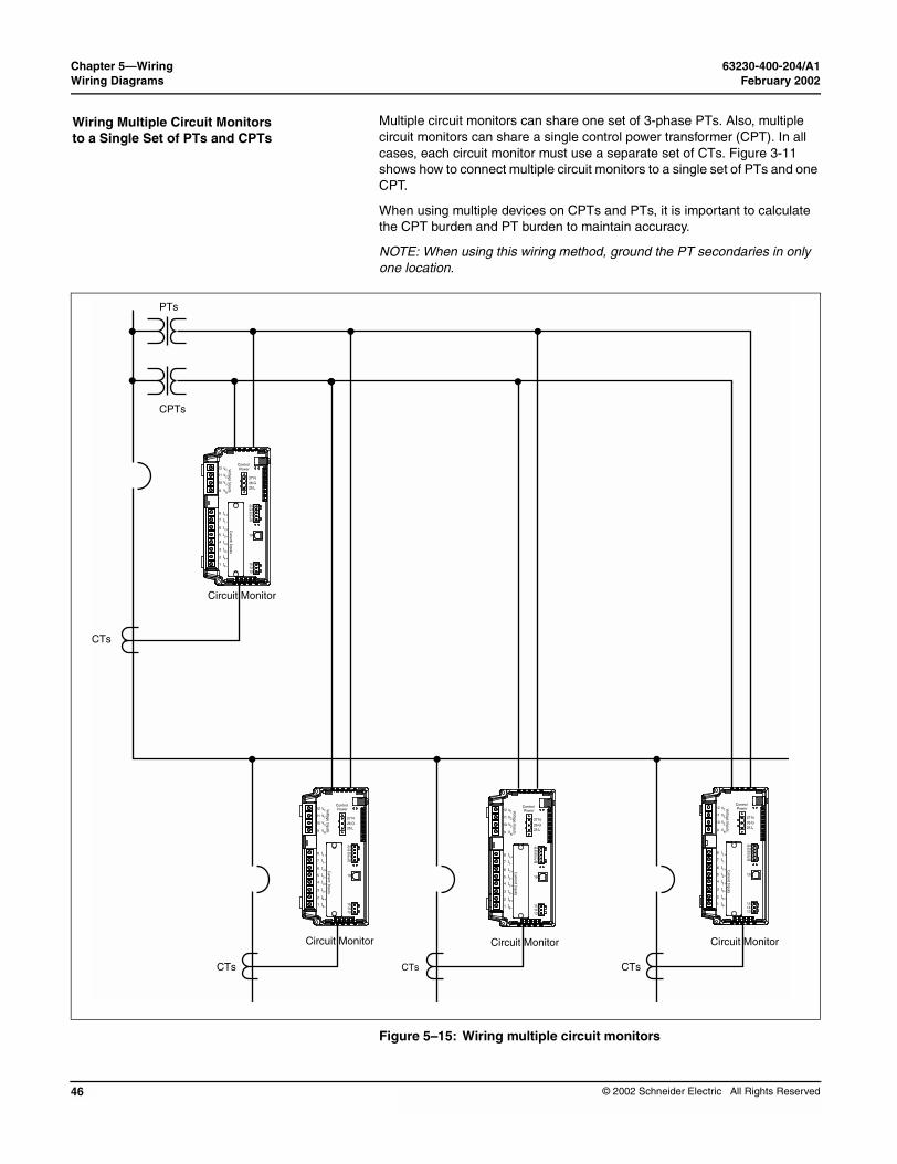
If you are using control power transformers (CPTs), refer to Table 5–1 to see the correct CPT size to use for the number of circuit monitors.
Table 5–1: Control Power Transformer Sizing
Number of Circuit Monitors Size of the CPT
1–10 500 VA
11–20 1,000 VA
21–30 1500 VA
31–40 2000 VA
DANGERHAZARD OF ELECTRIC SHOCK, BURN, OR EXPLOSION
• Only qualified workers should install and wire the circuit monitor. Perform this work only after completely reading the installation and wiring chapters.
• Turn off all power supplying the circuit monitor and the equipment in which it is installed before working on it.
• Use a properly rated voltage testing device to verify that the power is off.
Failure to follow these instructions will result in death or serious injury.
© 2002 Schneider Electric All Rights Reserved

63230-400-204/A1 Chapter 5—WiringFebruary 2002 Requirements Before You Begin Wiring
© 2002 Schneider Electric All Rights Reserved
Control Power Fusing
Potential (Voltage) Transformers
The control power inputs of each circuit monitor should be individually fused under all circumstances. When deriving control power from either a control power transformer or a metering potential transformer where the secondary voltage is 250 Vac or less, use a standard 1 A time-delay, 250 Vac fuse. An example of a suitable fuse is the Bussmann FNM. If the control power is derived directly from the line voltage (305 Vac or less), use a rejection type time-delay fuse rated for 600 V, 3 A such as the Bussman type FNQ-R. For European safety compliance (EN61010 / LVD), see “Required Protection for CE Compliance” on page 32 for details on installation of protection devices in the control power circuit.
Potential transformers (PTs), sometimes referred to as voltage transformers (VTs), are not required on the voltage metering inputs with line-to-line voltages of 600 V or less. Connect the voltage metering inputs directly to the line voltages. However, for power systems with voltages higher than 600 V line-to-line, you must use potential transformers.
31
Chapter 5—Wiring 63230-400-204/A1Requirements Before You Begin Wiring February 2002
32
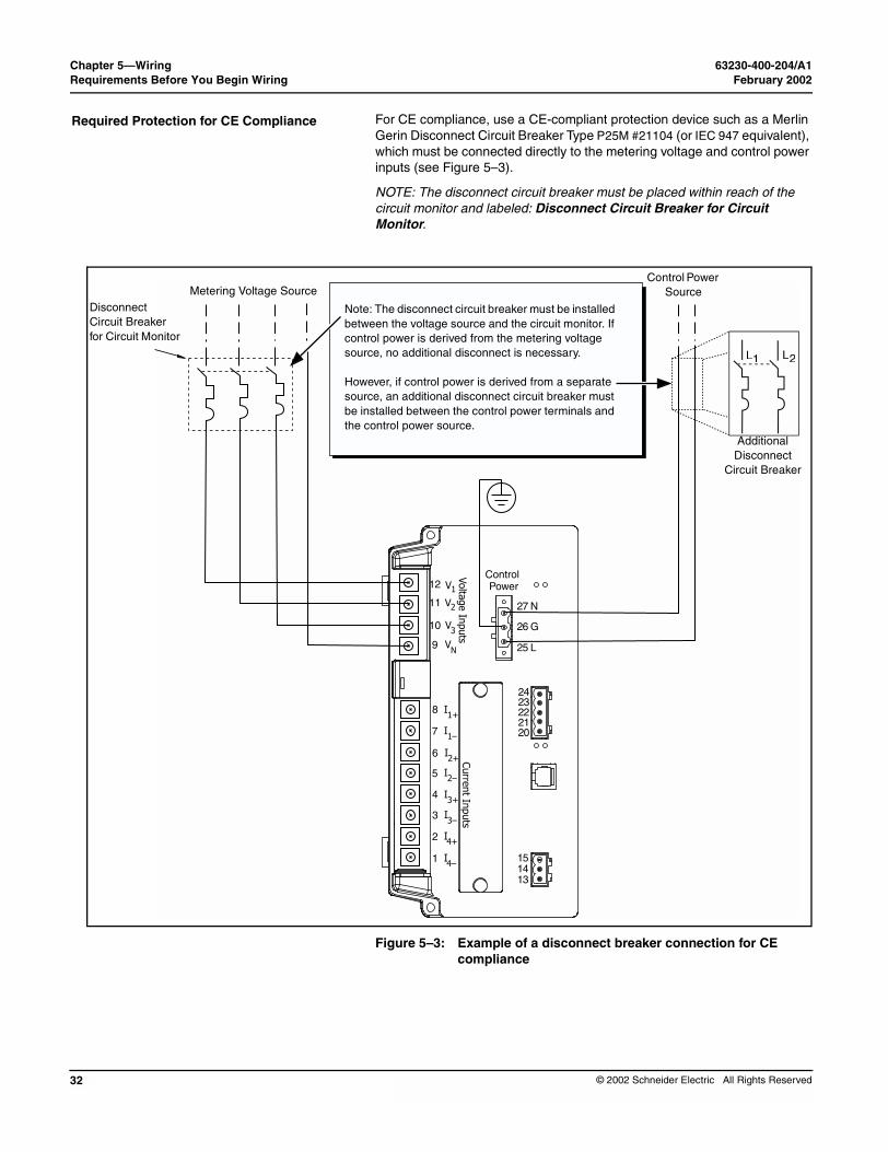
Required Protection for CE Compliance
Notbetwconsou
Howsoube ithe
Metering Voltage SourceDisconnect Circuit Breaker for Circuit Monitor
For CE compliance, use a CE-compliant protection device such as a Merlin Gerin Disconnect Circuit Breaker Type P25M #21104 (or IEC 947 equivalent), which must be connected directly to the metering voltage and control power inputs (see Figure 5–3).
NOTE: The disconnect circuit breaker must be placed within reach of the circuit monitor and labeled: Disconnect Circuit Breaker for Circuit Monitor.
Figure 5–3: Example of a disconnect breaker connection for CE compliance
L1 L2
Volta
ge In
puts
Curre
nt In
puts
Control Power12
11
10
9
8
27 N
26 G
25 L
7
6
5
4
3
2
1
V
V2
3
N
1+
V
V
I
1–I
2+I
2–I
3+I
3–
4+I
4–I
2423222120
151413
1
I
e: The disconnect circuit breaker must be installed een the voltage source and the circuit monitor. If
trol power is derived from the metering voltage rce, no additional disconnect is necessary.
ever, if control power is derived from a separate rce, an additional disconnect circuit breaker must nstalled between the control power terminals and control power source.
Control Power Source
Additional Disconnect
Circuit Breaker
© 2002 Schneider Electric All Rights Reserved

63230-400-204/A1 Chapter 5—WiringFebruary 2002 Wiring CTs, PTs, and Control Power to the Circuit Monitor
© 2002 Schneider Electric All Rights Reserved
WIRING CTS, PTS, AND CONTROL POWER TO THE CIRCUIT MONITOR
Table 5–2: Supported Types of System Connec
System WiringNumber of CTs
Auxiliary CT
Numof P
3∅, 3-WireDelta
2 None 2
3 None 2
3∅, 4-Wire Wye,
Ground
3 None 3
4 Neutral 3
3 None 2
4 Neutral 2
➀ The “system type” is a code assigned to each type of ➁ Indicates a value that is calculated rather than measu
The circuit monitor supports a variety of 3-phase power system wiring connections, including 3-wire delta and 4-wire wye. The metering voltage inputs support direct connection to 3-phase power systems from 208V L–L/120V L–N through 600V L-L/347V L–N. In addition, the circuit monitor supports higher voltages through potential transformers (PTs). The circuit monitor can also be used with line-to-line rated PTs connected line to neutral, which results in a line-to-neutral voltage of 69 V. Table 5–2 lists the supported system connections and references the wiring diagrams on pages 35 through 44. Figures 5–4 through 5–13 beginning on page 35 show wiring to the circuit monitor for connections to the current transformers CTs, PTs, and control power. Figure 5–14 on page 45 shows dc control power.
tions
ber Ts
PT Connection
Currents VoltagesSystem Type➀
Figure Number
Open Delta
A, B➁, C A-B, B-C, C-A➁ 3∅3W2CT(30)
Figure 5–5 on page 36
A, B, C A-B,B-C,C-A➁ 3∅3W3CT(31)
Figure 5–6 on page 37
Wye-Wye
A, B, C, N➁ A-N, B-N, C-NA-B➁, B-C➁,
C-A➁
3∅4W3CT(40)
Figure 5–7 on page 38
A, B, C, N, G➁ A-N, B-N, C-NA-B➁, B-C➁,
C-A➁
3∅4W4CT(41)
Figure 5–8 on page 39
Open Wye
A, B, C, N➁ A-N, B-N➁, C-N
A-B➁, B-C➁, C-A➁
3∅4W3CT2PT(42)
Figure 5–11 on page 42
A, B, C, N, G➁ A-N, B-N➁, C-N
A-B➁, B-C➁, C-A➁
3∅4W4CT2PT(43)
Figure 5–12 on page 43
system connection.
red directly.
33

Chapter 5—Wiring 63230-400-204/A1Wiring CTs, PTs, and Control Power to the Circuit Monitor February 2002
34
Making the Connections
Follow these step to make the connections to the voltage and current inputs:Notes:
• When wiring the circuit monitor, do not route wires over unused option card slot. Do not block the circuit monitor vents with the wires. See “Mounting” on page 15 for clearances.
• For CE wiring requirements, see “Required Protection for CE Compliance” on page 32.
To wire the circuit monitor, refer to the appropriate wiring diagram (see “Wiring Diagrams” on page 35.
1. Strip .25 in (6 mm) of insulation from the wire ends. Using a suitable crimping tool, crimp the yellow spade lugs onto the wires for the voltage, current, and control power inputs on the circuit monitor.
2. Loosen the terminal screws for each terminal on the circuit monitor and insert the spade lug under the washer. Torque the screws 6–9 lb-in (0.68–1 N•m).
3. Ground the circuit monitor. See “Grounding the Circuit Monitor” on page 49 for instructions.
4. Install the plastic terminal cover over the terminal.
HAZARD OF ELECTRIC SHOCK, BURN, OR EXPLOSION
• Never short the secondary of a PT.
• Never open circuit a CT; use the shorting block to short circuit the leads of the CT before removing the connection from the circuit monitor.
• Turn off all power to the equipment in which the circuit monitor is installed before working on it.
• Use a properly rated voltage testing device to verify that the power is off.
Failure to follow this instruction will result in death or serious injury.
DANGER
© 2002 Schneider Electric All Rights Reserved

63230-400-204/A1 Chapter 5—WiringFebruary 2002 Wiring Diagrams
© 2002 Schneider Electric All Rights Reserved
WIRING DIAGRAMS
Line
AØ
BØ
CØ
CT Shorting Block
Only when L–Lvoltage is below 305 Vac
Fuses
Notes:
• Control power can be drawn from fused voltage inputs L-L or an external source. See page 30 for recommendations about CPTs and fusing.
• Control power range: 90–305 Vac, 100–300 Vdc
• Installation Category III below 300 V
• Pay close attention to polarity marks ( ) when connnecting CTs.
• For corner grounded delta applications, use PTs as shown in Figure 5–7 on page 38.
• Use system type: 3Ø3W2CT
Figure 5–4: 3-Phase, 3-Wire Delta Direct Voltage Connection with 2 CTs
Voltage Disconnect Switch
Load
Volta
ge In
puts
Curre
nt In
puts
Control Power12
11
10
9
8
27 N26 G25 L
7
6
5
4
3
2
1
V
V2
3
N
1+
V
V
I
1–I
2+I
2–I
3+I
3–
4+I
4–I
RS-485 Data Communications
Display CommunicationsPort
KYZ
2423222120
19
151413
1
I
35

Chapter 5—Wiring 63230-400-204/A1Wiring Diagrams February 2002
36
Line
AØ
BØ
CØ
CT Shorting Block
Install jumper between Vand Vn when using VTs o3-wire system. Do not usjumper for a direct voltagconnection (no VTs.)
Notes:
• Control power can be drawn from fused PT secondary voltage inputs L-L or an external source. See page 30 for recommendations about CPTs and fusing.
• Control power range: 90–305 Vac, 100–300 Vdc
• Installation Category III
• Pay close attention to polarity marks ( ) when connnecting CTs and PTs.
• Use system type: 3Ø3W2CT
Figure 5–5: 3-Phase, 3-Wire Delta Connection with 2 PTs and 2 CTs
Voltage Disconnect Switch
Control PowerDisconnect Switch
Fuses
Open Delta PT Connection120V L–L Secondaries
CPT 120 or 240VacSecondary, 50 VA max.
Fuses
Load
2 n a
e a e
Volta
ge In
puts
Curre
nt In
puts
Control Power12
11
10
9
8
27 N26 G25 L
7
6
5
4
3
2
1
V
V2
3
N
1+
V
V
I
1–I
2+I
2–I
3+I
3–
4+I
4–I
RS-485 Data Communications
Display CommunicationsPort
KYZ
2423222120
19
151413
1
I
© 2002 Schneider Electric All Rights Reserved

63230-400-204/A1 Chapter 5—WiringFebruary 2002 Wiring Diagrams
© 2002 Schneider Electric All Rights Reserved
Line
AØ
BØ
CØ
CT Shorting Block
Install jumper between and Vn when using VTsa 3-wire system. Do noa jumper for a direct voconnection (no VTs.)
Notes:
• Control power can be drawn from fused PT secondary voltage inputs L-L or an external source. See page 30 for recommendations about CPTs and fusing.
• Control power range: 90–305 Vac, 100–300 Vdc
• Installation Category III
• Pay close attention to polarity marks ( ) when connnecting CTs and PTs.
• Use system type: 3Ø3W3CT
Figure 5–6: 3-Phase, 3-Wire Delta Connection with 2 PTs and 3 CTs
Voltage Disconnect Switch
Current Disconnect Switch
Fuses
Open Delta PT Connection120V L–L Secondaries
CPT 120 or 240 VacSecondary, 50 VA max
Fuses
Load
V2 on
t use ltage
Volta
ge In
puts
Curre
nt In
puts
Control Power12
11
10
9
8
27 N26 G25 L
7
6
5
4
3
2
1
V
V2
3
N
1+
V
V
I
1–I
2+I
2–I
3+I
3–
4+I
4–I
RS-485 Data Communications
Display CommunicationsPort
KYZ
2423222120
19
151413
1
I
37
Chapter 5—Wiring 63230-400-204/A1Wiring Diagrams February 2002
38
Voltage Disconnect Switch
Fuses
Line
AØ
BØ
CØ
N
CT Shorting Block
Notes:
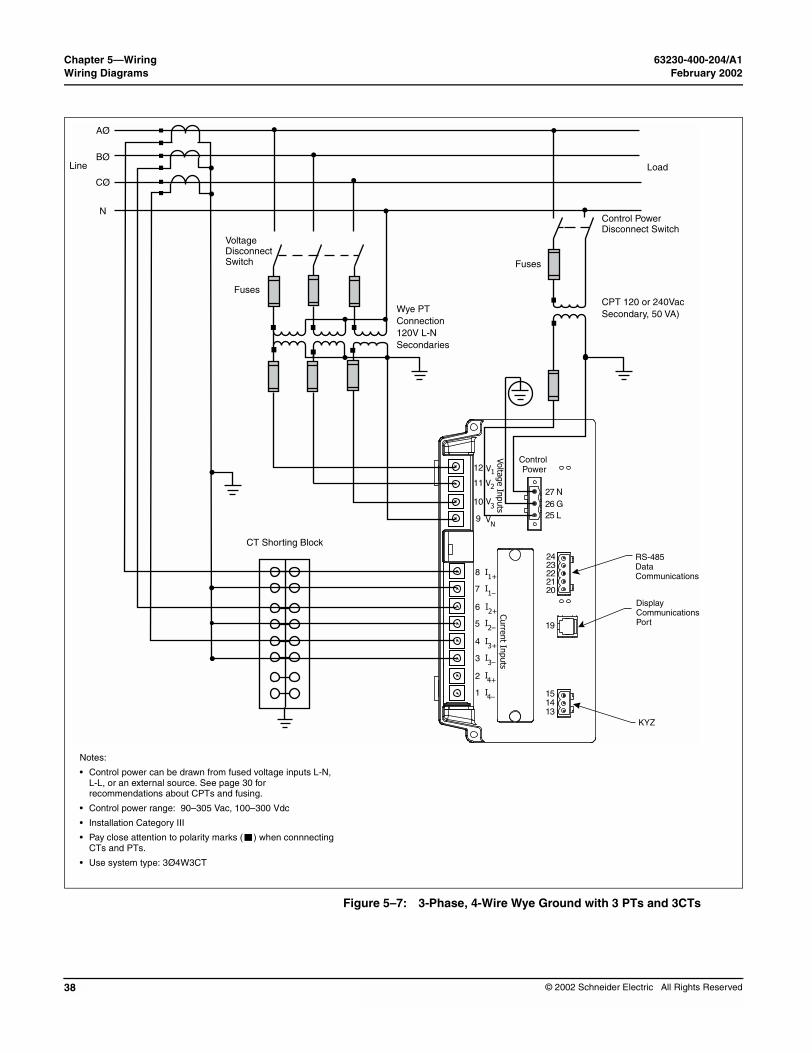
• Control power can be drawn from fused voltage inputs L-N, L-L, or an external source. See page 30 for recommendations about CPTs and fusing.
• Control power range: 90–305 Vac, 100–300 Vdc
• Installation Category III
• Pay close attention to polarity marks ( ) when connnectingCTs and PTs.
• Use system type: 3Ø4W3CT
Figure 5–7: 3-Phase, 4-Wire Wye Ground with 3 PTs and 3CTs
Volta
ge In
puts
Curre
nt In
puts
Control Power12
11
10
9
8
27 N26 G25 L
7
6
5
4
3
2
1
V
V2
3
N
1+
V
V
I
1–I
2+I
2–I
3+I
3–
4+I
4–I
RS-485 Data Communications
Display CommunicationsPort
KYZ
2423222120
19
151413
1
I
Control PowerDisconnect Switch
Wye PT Connection120V L-N Secondaries
CPT 120 or 240VacSecondary, 50 VA)
Fuses
Load
© 2002 Schneider Electric All Rights Reserved

63230-400-204/A1 Chapter 5—WiringFebruary 2002 Wiring Diagrams
© 2002 Schneider Electric All Rights Reserved
Voltage Disconnect Switch
Fuses
Line
AØ
BØ
CØ
N
CT Shorting Block
Notes:
• Control power can be drawn from fused voltage PT secondainputs L-N, L-L, or an external source. See page 30 for recommendations about CPTs and fusing.
• Control power range: 90–305 Vac, 100–300 Vdc
• Installation Category III
• Pay close attention to polarity marks ( ) when connnecting CTs and PTs.
• Use system type: 3Ø4W4CT
Figure 5–8: 3-Phase, 4-Wire Wye Ground Connection with 3 PTs and 4 CTs
Control PowerDisconnect Switch
Wye PT Connection120V L-N Secondaries
CPT 120 or 240VacSecondary, 50 VA
Fuses
Load
Volta
ge In
puts
Curre
nt In
puts
Control Power12
11
10
9
8
27 N26 G25 L
7
6
5
4
3
2
1
V
V2
3
N
1+
V
V
I
1–I
2+I
2–I
3+I
3–
4+I
4–I
RS-485 Data Communications
Display CommunicationsPort
KYZ
2423222120
19
151413
1
I
ry
39

Chapter 5—Wiring 63230-400-204/A1Wiring Diagrams February 2002
40
Voltage Disconnect Switch
Fuses
Line
AØ
BØ
CØ
N
CT Shorting Block
Notes:
• Control power can be drawn from fused voltage inputs L-N, L-L, or an external source. See page 30 for recommendations about CPTs and fusing.
• Control power range: 90–305 Vac, 100–300 Vdc
• Use with 480/277 V and 208/120 V systems
• Use system type: 3Ø4W3CT
• Installation Category III below 300 Vac
• Pay close attention to polarity marks ( ) when connnecting CTs.
• Use system type: 3Ø4W3CT
Figure 5–9: 3-Phase, 4-Wire Wye with Direct Voltage Connection and 3CTs
Load
Only when L–Nvoltage is below 305 Vac
Volta
ge In
puts
Curre
nt In
puts
Control Power12
11
10
9
8
27 N26 G25 L
7
6
5
4
3
2
1
V
V2
3
N
1+
V
V
I
1–I
2+I
2–I
3+I
3–
4+I
4–I
RS-485 Data Communications
Display CommunicationsPort
KYZ
2423222120
19
151413
1
I
© 2002 Schneider Electric All Rights Reserved

63230-400-204/A1 Chapter 5—WiringFebruary 2002 Wiring Diagrams
© 2002 Schneider Electric All Rights Reserved
Voltage Disconnect Switch
Fuses
Fuses
Line
AØ
BØ
CØ
N
CT Shorting Block
Notes:
• Control power can be drawn from fused PT secondary voltage inputs L-L, L-N, or an external source. See page 30 for recommendations about CPTs and fusing.
• Control power range: 90–305 Vac, 100–300 Vdc
• Installation Category III
• Pay close attention to polarity marks ( ) when connnecting CTs and PTs.
• Use system type: 3Ø4W3CT
Figure 5–10: 3-Phase, 3-Wire Wye, 3-Wire Balanced Load with 3 PTs and 2 CTs
Volta
ge In
puts
Curre
nt In
puts
Control Power12
11
10
9
8
27 N26 G25 L
7
6
5
4
3
2
1
V
V2
3
N
1+
V
V
I
1–I
2+I
2–I
3+I
3–
4+I
4–I
RS-485 Data Communications
Display CommunicationsPort
KYZ
2423222120
19
151413
1
I
Control PowerDisconnect Switch
Wye PT Connection120V L-N Secondaries
CPT 120 or 240 Vac SecondaryProjected 50 VA max.
Fuses
3- Wire Load
41

Chapter 5—Wiring 63230-400-204/A1Wiring Diagrams February 2002
42
Voltage Disconnect Switch
Fuses
Line
AØ
BØ
CØ
N
CT Shorting Block
Notes:
• Control power can be drawn from fused PT secondary voltage inputs L-L, L-N, or an external source. See page 30 for recommendations about CPTs and fusing.
• Control power range: 90–305 Vac, 100–300 Vdc
• Installation Category III
• Pay close attention to polarity marks ( ) when connnecting CTs and PTs.
• Use system type: 3Ø4W3CT2PT
Figure 5–11: 3-Phase, 4-Wire Wye with 3CTs and 2 PTs (calculated neutral).
Control PowerDisconnect Switch
Wye PT Connection120V L–N Secondaries
CPT 120 or 240 VacSecondary, 50 VA max.
Fuses
Load
Volta
ge In
puts
Curre
nt In
puts
Control Power12
11
10
9
8
27 N26 G25 L
7
6
5
4
3
2
1
V
V2
3
N
1+
V
V
I
1–I
2+I
2–I
3+I
3–
4+I
4–I
RS-485 Data Communications
Display CommunicationsPort
KYZ
2423222120
19
151413
1
I
© 2002 Schneider Electric All Rights Reserved

63230-400-204/A1 Chapter 5—WiringFebruary 2002 Wiring Diagrams
© 2002 Schneider Electric All Rights Reserved
Voltage Disconnect Switch
Fuses
Fuses
Line
AØ
BØ
CØ
N
CT Shorting Bloc
Notes:
• Control power can be drawn from fused PT secondary voltage inputs L-L, L-N, or an external source. See page 30 for recommendations about CPTs and fusing.
• Control power range: 90–305 Vac, 100–300 Vdc
• Installation Category III
• Pay close attention to polarity marks ( ) when connnecting CTs and PTs.
• Use system type: 3Ø4W4CT2PT
Figure 5–12: 3-Phase, 4-Wire Wye with 4 CTs and 2 PTs
Control Power Disconnect Switch
Wye PT Connection120V L–N Secondaries
CPT 120 or 240 Vac SecondarProjected 50 VA
Fuses
Load
k
Volta
ge In
puts
Curre
nt In
puts
Control Power12
11
10
9
8
27 N26 G25 L
7
6
5
4
3
2
1
V
V2
3
N
1+
V
V
I
1–I
2+I
2–I
3+I
3–
4+I
4–I
RS-485 Data Communications
Display CommunicationsPort
KYZ
2423222120
19
151413
1
I
43

Chapter 5—Wiring 63230-400-204/A1Wiring Diagrams February 2002
44
Line
L1
N
L2
CT Shorting Bloc
Only when L–Nvoltage is below 305 Vac
Fuses
Notes:
• Control power can be drawn from fused voltage inputs L-L or an external source. See page 30 for recommendations about CPTs and fusing.
• Control power range: 90–305 Vac, 100–300 Vdc
• Installation Category III
• Pay close attention to polarity marks ( ) when connnecting CTs.
• When configuring the circuit monitor, set system type to 4-wire (40).
Figure 5–13: 1-Phase, 3-Wire Direct Voltage Connection with 2 CTs
Voltage Disconnect Switch
Load
k
Volta
ge In
puts
Curre
nt In
puts
Control Power12
11
10
9
8
27 N26 G25 L
7
6
5
4
3
2
1
V
V2
3
N
1+
V
V
I
1–I
2+I
2–I
3+I
3–
4+I
4–I
RS-485 Data Communications
Display CommunicationsPort
KYZ
2423222120
19
151413
1
I
© 2002 Schneider Electric All Rights Reserved

63230-400-204/A1 Chapter 5—WiringFebruary 2002 Wiring Diagrams
© 2002 Schneider Electric All Rights Reserved
Notes:
• Control power range: 100–300 Vdc
Figure 5–14: DC Control Power Wiring
Fuse
DC Control Power120/250 Vdc Nominal
(+) (–)
Volta
ge In
puts
Curre
nt In
puts
Control Power12
11
10
9
8
27 N26 G25 L
7
6
5
4
3
2
1
V
V2
3
N
1+
V
V
I
1–I
2+I
2–I
3+I
3–
4+I
4–I
RS-485 Data Communications
Display CommunicationsPort
KYZ
2423222120
19
151413
1
I
45
Chapter 5—Wiring 63230-400-204/A1Wiring Diagrams February 2002
46
Wiring Multiple Circuit Monitors to a Single Set of PTs and CPTs
PTs
CPTs
Circuit Monitor
Circuit Monito
CTs
CTs
Volta
ge In
puts
Curre
nt In
puts
Control Power12
11
10
9
8
27 N26 G25 L
7
6
5
4
3
2
1
V
V2
3
N
1+
V
V
I
1–I
2+I
2–I
3+I
3–
4+I
4–I
2423222120
19
151413
1
I
Volta
ge In
puts
Curre
nt In
puts
Control Power12
11
10
9
8
27 N26 G25 L
7
6
5
4
3
2
1
V
V2
3
N
1+
V
V
I
1–I
2+I
2–I
3+I
3–
4+I
4–I
2423222120
19
151413
1
I
Multiple circuit monitors can share one set of 3-phase PTs. Also, multiple circuit monitors can share a single control power transformer (CPT). In all cases, each circuit monitor must use a separate set of CTs. Figure 3-11 shows how to connect multiple circuit monitors to a single set of PTs and one CPT.
When using multiple devices on CPTs and PTs, it is important to calculate the CPT burden and PT burden to maintain accuracy.
NOTE: When using this wiring method, ground the PT secondaries in only one location.
Figure 5–15: Wiring multiple circuit monitors
r Circuit Monitor Circuit Monitor
CTsCTs
Volta
ge In
puts
Curre
nt In
puts
Control Power12
11
10
9
8
27 N26 G25 L
7
6
5
4
3
2
1
V
V2
3
N
1+
V
V
I
1–I
2+I
2–I
3+I
3–
4+I
4–I
2423222120
19
151413
1
I
Volta
ge In
puts
Curre
nt In
puts
Control Power12
11
10
9
8
27 N26 G25 L
7
6
5
4
3
2
1
V
V2
3
N
1+
V
V
I
1–I
2+I
2–I
3+I
3–
4+I
4–I
2423222120
19
151413
1
I
© 2002 Schneider Electric All Rights Reserved

63230-400-204/A1 Chapter 5—WiringFebruary 2002 Wiring Diagrams
© 2002 Schneider Electric All Rights Reserved
Deriving Control Power from Phase PT Inputs
Whenever possible, obtain control power for the circuit monitor from a stable voltage source separate from the metering inputs. If such a source is unavailable, the circuit monitor can derive control power from its active phase PT inputs. Because of the wide range of permissible control power inputs, the circuit monitor can accept either line-to-neutral (L–N) or line-to-line (L–L) control power inputs up to 240 V nominal. If you use the L–L control power option, the circuit monitor ride-through time increases and enables more reliable operation during voltage disturbances.
Referring to Figure 5–16 on page 48 and Figure 5–17 on page 48, complete the following steps to obtain control power from phase PT inputs:
1. Connect the V1 terminal (terminal 12) to the L terminal (terminal 25).2. For L-L control power, connect the V3 terminal (terminal 10) to the N
terminal (terminal 27). For L-N control power, connect the Vn terminal (terminal 9) to the N terminal (terminal 27).
3. Close the protective terminal strip cover.
OVERLOADED PT.
When deriving control power from the phase PT inputs, the phase PT used must have a VA rating sufficient for all connected burdens. If excessive burden is placed on the metering PT, it could reduce the voltage transformer’s accuracy or damage the PT.
Failure to follow this instruction can reduce metering accuracy.
CAUTION
47

Chapter 5—Wiring 63230-400-204/A1Wiring Diagrams February 2002
48
Volta
ge In
puts
Curre
nt In
puts
Control Power12
11
10
9
8
27 N26 G25 L
7
6
5
4
3
2
1
V
V2
3
N
1+
V
V
I
1–I
2+I
2–I
3+I
3–
4+I
4–I
2423222120
19
151413
1
I
Volta
ge In
puts
Curre
nt In
puts
Control Power12
11
10
9
8
27 N26 G25 L
7
6
5
4
3
2
1
V
V2
3
N
1+
V
V
I
1–I
2+I
2–I
3+I
3–
4+I
4–I
2423222120
19
151413
1
I
phase PT Figure 5–17: Deriving L-N control power from phase PT inputs (305 Vac maximum)
Figure 5–16: Deriving L-L control power frominputs (305 Vac maximum)
© 2002 Schneider Electric All Rights Reserved

63230-400-204/A1 Chapter 5—WiringFebruary 2002 Grounding the Circuit Monitor
© 2002 Schneider Electric All Rights Reserved
GROUNDING THE CIRCUIT MONITOR
To ground the circuit monitor, connect the ground terminal (terminal 26) of the circuit monitor to a true earth ground, using 14 AWG copper wire or larger (see Figure 5–18).NOTE: You must ground the circuit monitor as described in these instructions. Do not use the mounting panel or equipment door as a true earth ground. Connect the circuit monitor ground terminal to a true earth ground bus. Failure to properly ground the circuit monitor may induce noise on the metering inputs.
Figure 5–18: Connector for grounding the circuit monitor
Volta
ge In
puts
Curre
nt In
puts
Control Power12
11
10
9
8
27 N26 G25 L
7
6
5
4
3
2
1
V
V2
3
N
1+
V
V
I
1–I
2+I
2–I
3+I
3–
4+I
4–I
2423222120
19
151413
1
I
14 AWG copper wire or larger
49
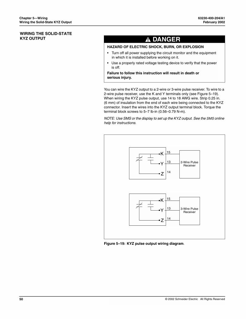
Chapter 5—Wiring 63230-400-204/A1Wiring the Solid-State KYZ Output February 2002
50
WIRING THE SOLID-STATE KYZ OUTPUT
You can wire the KYZ output to a 2-wire or 3-wire pulse receiver. To wire to a 2-wire pulse receiver, use the K and Y terminals only (see Figure 5–19). When wiring the KYZ pulse output, use 14 to 18 AWG wire. Strip 0.25 in. (6 mm) of insulation from the end of each wire being connected to the KYZ connector. Insert the wires into the KYZ output terminal block. Torque the terminal block screws to 5–7 lb-in (0.56–0.79 N-m).
NOTE: Use SMS or the display to set up the KYZ output. See the SMS online help for instructions.
Figure 5–19: KYZ pulse output wiring diagram.
HAZARD OF ELECTRIC SHOCK, BURN, OR EXPLOSION
• Turn off all power supplying the circuit monitor and the equipment in which it is installed before working on it.
• Use a properly rated voltage testing device to verify that the power is off.
Failure to follow this instruction will result in death or serious injury.
DANGER
K
Y
Z
2-Wire PulseReceiver
15
13
14
K
Y
Z
3-Wire PulseReceiver
15
13
14
© 2002 Schneider Electric All Rights Reserved

63230-400-204/A1 Chapter 5—WiringFebruary 2002 Wiring Error Detection
© 2002 Schneider Electric All Rights Reserved
WIRING ERROR DETECTION
Running the Diagnostics Wiring Error Test
The circuit monitor can diagnose possible wiring errors when you initiate the wiring test on the Diagnostics menu. Running the test is not required, but may help you to pinpoint a potentially miswired connection. Before running the wiring test, you must first wire the circuit monitor and perform the minimum set up of the circuit monitor, which includes setting up these parameters:
• CT primary and secondary• PT primary and secondary• System type
• Frequency
After you have wired and completed the minimum set up, run the wiring test to verify proper wiring of your circuit monitor. The wiring test assumes that the following is true about your system:
• Voltage connection Van (4-wire) or Vab (3-wire) is correct. This connection must be properly wired for the wiring check program to work.
• 3-phase system. The system must be a 3-phase system. You cannot perform a wiring check on a single-phase system.
• System type. The wiring check can be performed only on the six possible system types (see Table 5–2 on page 33 for a description of system types).
• Expected displacement power factor is between .60 lagging and .99 leading.
• The load must be at least 1% of the CT Primary setting.
This wiring error program is based on the assumptions above and based on a typical wiring system, results may vary depending on your system and some errors may not apply to your system. When the wiring test is run, the program performs the following checks in this order:
1. Verifies that the system type is one of those listed above.2. Verifies that the frequency is within ±5% of the frequency that you
selected in circuit monitor set up.3. Verifies that the voltage phase angles are 120° apart. If the voltage
connections are correct, the phase angles will be 120° apart.If the voltage connections are correct, the test continues.
4. Verifies that the measured phase rotation is the same as the phase rotation set up in the circuit monitor.
5. Verifies the magnitude of the currents to see if there is enough load on each phase input to perform the check.
6. Indicates if the 3-phase real power (kW) total is negative, which could indicate a wiring error.
7. Compares each current angle to its respective voltage.
When the circuit monitor detects a possible error, you can find and correct the problem and then run the check again. Repeat the procedure until no error messages are displayed. To perform a wiring diagnostic test, follow these steps:
51
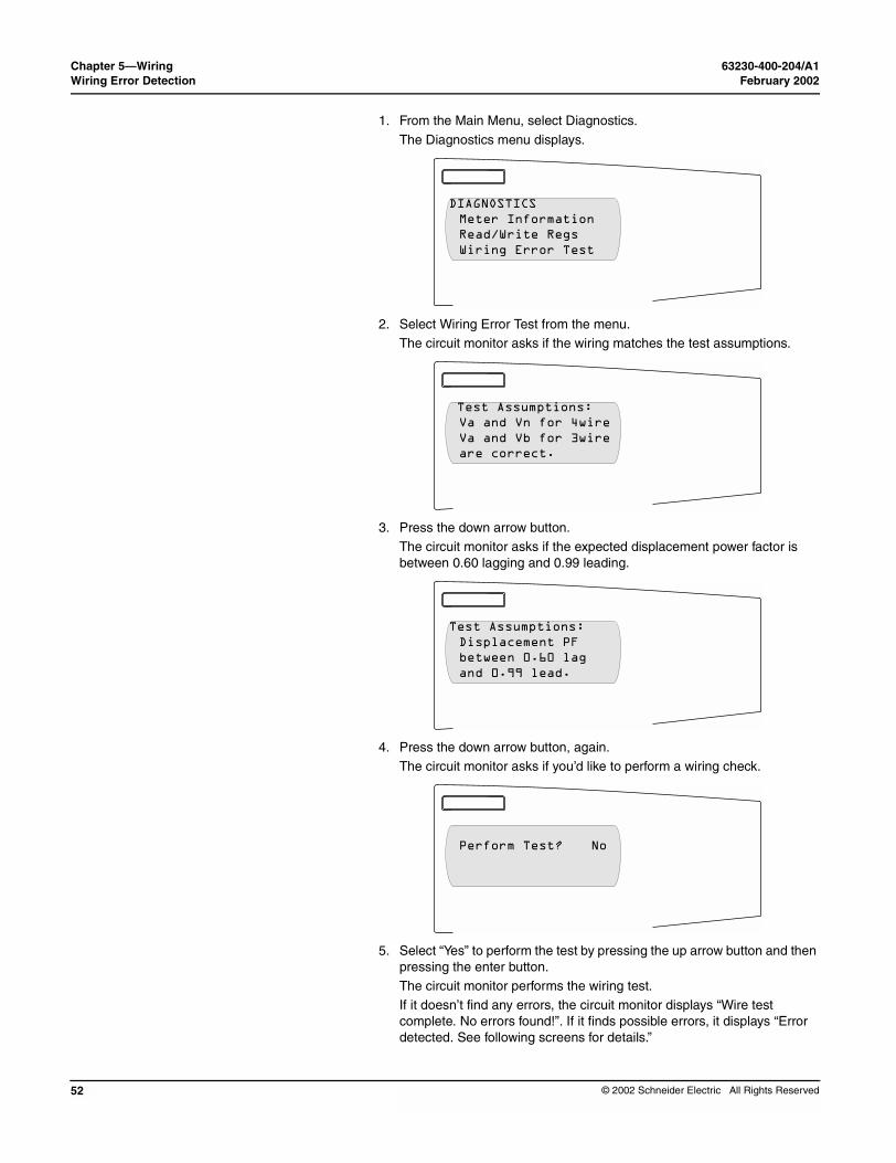
Chapter 5—Wiring 63230-400-204/A1Wiring Error Detection February 2002
52
1. From the Main Menu, select Diagnostics.
The Diagnostics menu displays.
2. Select Wiring Error Test from the menu.The circuit monitor asks if the wiring matches the test assumptions.
3. Press the down arrow button.The circuit monitor asks if the expected displacement power factor is between 0.60 lagging and 0.99 leading.
4. Press the down arrow button, again.The circuit monitor asks if you’d like to perform a wiring check.
5. Select “Yes” to perform the test by pressing the up arrow button and then pressing the enter button.The circuit monitor performs the wiring test.If it doesn’t find any errors, the circuit monitor displays “Wire test complete. No errors found!”. If it finds possible errors, it displays “Error detected. See following screens for details.”
DIAGNOSTICSMeter InformationRead/Write RegsWiring Error Test
Test Assumptions:Va and Vn for 4wireVa and Vb for 3wireare correct.
Test Assumptions:Displacement PFbetween 0.60 lagand 0.99 lead.
Perform Test? No
© 2002 Schneider Electric All Rights Reserved

63230-400-204/A1 Chapter 5—WiringFebruary 2002 Wiring Error Detection
© 2002 Schneider Electric All Rights Reserved
Table 5–3: Wiring Error Messages
Message
Invalid system type
Frequency out of range
Voltage not present on all phases
Severe voltage unbalance present
Not enough load to check wiring
Suspected error: Check meter configuration for direct co
Suspected error: Reverse polarity on all current inputs
Phase rotation does not match meter setup
Negative kW, check CT & VT polarities
No voltage metered on V1–n
No voltage metered on V2–n
No voltage metered on V3–n
No voltage metered on V1–2
No voltage metered on V2–3
No voltage metered on V3-1
V2–n phase angle out of range
V3–n phase angle out of range
V2–3 phase angle out of range
6. Press the arrow buttons to scroll through the wiring error messages.
Table 5–3 explains the possible wiring error messages.7. Turn off all power supplying the circuit monitor. Verify that the power is off
using a properly rated voltage testing device.
8. Correct the wiring errors.
9. Repeat these steps until all errors are corrected.
Description
The circuit monitor is set up for a system type that the wiring test does not support.
Actual frequency of the system is not the same as the selected frequency configured for the circuit monitor.
No voltage metered on one or more phases.
Voltage unbalance on any phase greater than 70%.
Metered current below deadband on one or more phases.
nnection Set up for voltage input should be “No PT.”
Check polarities. Polarities on all CTs could be reversed.
Metered phase rotation is different than phase rotation selected in the circuit monitor set up.
Metered kW is negative, which could indicate swapped polarities on any CT or VT.
No voltage metered on V1–n on 4-wire system only.
No voltage metered on V2–n on 4-wire system only.
No voltage metered on V3–n on 4-wire system only.
No voltage metered on V1–2.
No voltage metered on V2–3.
No voltage metered on V3-1.
V2–n phase angle out of expected range.
V3–n phase angle out of expected range.
V2–3 phase angle out of expected range.
HAZARD OF ELECTRIC SHOCK, BURN, OR EXPLOSION
• Turn off all power supplying the circuit monitor and the equipment in which it is installed before working on it.
• Use a properly rated voltage testing device to verify that the power is off.
• Never short the secondary of a PT.
• Never open circuit a CT; use the shorting block to short circuit the leads of the CT before removing the connection from the circuit monitor.
Failure to follow this instruction will result in death or serious injury.
DANGER
53

Chapter 5—Wiring 63230-400-204/A1Wiring Error Detection February 2002
54
V3–1 phase angle out of range
Suspected error: Reverse polarity on V2–n VT
Suspected error: Reverse polarity on V3–n VT
Suspected error: Reverse polarity on V2–3 VT
Suspected error: Polarity on V3–1 VT
Suspected error: Check V1 input, may be V2 VT
Suspected error: Check V2 input, may be V3 VT
Suspected error: Check V3 input, may be V1 VT
Suspected error: Check V1 input, may be V3 VT
Suspected error: Check V2 input, may be V1 VT
Suspected error: Check V3 input, may be V2 VT
I1 load current less than 1% CT
I2 load current less than 1% CT
I3 load current less than 1% CT
I1 phase angle out of range. Cause of error unknown.
I2 phase angle out of range. Cause of error unknown
I3 phase angle out of range. Cause of error unknown.
Suspected error: Reverse polarity on I1 CT.
Suspected error: Reverse polarity on I2 CT
Suspected error: Reverse polarity on I3 CT
Suspected error: Check I1 input, may be I2 CT
Suspected error: Check I2 input, may be I3 CT
Suspected error: Check I3 input, may be I1 CT
Suspected error: Check I1 input, may be I3 CT
Suspected error: Check I2 input, may be I1 CT
Suspected error: Check I3 input, may be I2 CT
Suspected error: Check I1 input, may be I2 CT with reve
Suspected error: Check I2 input, may be I3 CT with reve
Suspected error: Check I3 input, may be I1 CT with reve
Suspected error: Check I1 input, may be I3 CT with reve
Suspected error: Check I2 input, may be I1 CT with reve
Suspected error. Check I3 input, may be I2 CT with reve
Table 5–3: Wiring Error Messages
Message
V3–1 phase angle out of expected range.
Polarity of V2–n VT could be reversed. Check polarity.
Polarity of V3–n VT could be reversed. Check polarity.
Polarity of V2–3 VT could be reversed. Check polarity.
Polarity of V3–1 VT could be reversed. Check polarity.
Phase 2 VT may actually be connected to input V1.
Phase 3 VT may actually be connected to input V12
Phase 1 VT may actually be connected to input V3.
Phase 3 VT may actually be connected to input V1.
Phase 1 VT may actually be connected to input V2.
Phase 2 VT may actually be connected to input V3.
Metered current on I1 less than 1% of CT. Test could not continue.
Metered current on I2 less than 1% of CT. Test could not continue.
Metered current on I3 less than 1% of CT. Test could not continue.
I1 phase angle is out of expected range. Cause of error unable to be determined.
I2 phase angle is out of expected range. Cause of error unable to be determined.
I3 phase angle is out of expected range. Cause of error unable to be determined.
Polarity of I1 CT could be reversed. Check polarity.
Polarity of I2 CT could be reversed. Check polarity.
Polarity of I3 CT could be reversed. Check polarity.
Phase 2 CT may actually be connected to input I1.
Phase 3 CT may actually be connected to input I2.
Phase 1 CT may actually be connected to input I3.
Phase 3 CT may actually be connected to input I1.
Phase 1 CT may actually be connected to input I2.
Phase 2 CT may actually be connected to input I3.
rse polarityPhase 2 CT may actually be connected to input I1, and the CT polarity may also be reversed.
rse polarityPhase 3 CT may actually be connected to input I21, and the CT polarity may also be reversed.
rse polarityPhase 1 CT may actually be connected to input I3, and the CT polarity may also be reversed.
rse polarityPhase 3 CT may actually be connected to input I1, and the CT polarity may also be reversed.
rse polarityPhase 1 CT may actually be connected to input I2, and the CT polarity may also be reversed.
rse polarityPhase 2 CT may actually be connected to input I3, and the CT polarity may also be reversed.
Description
© 2002 Schneider Electric All Rights Reserved

63230-400-204/A1 Chapter 6—Communications ConnectionsFebruary 2002 Chapter Contents
© 2002 Schneider Electric All Rights Reserved
CHAPTER 6—COMMUNICATIONS C
CHAPTER CONTENTS
CHAPTER CONTENTS . . . . . . . . . . . . . . . . . . . . . . . . . . . . . . . . . . . . . . 55COMMUNICATIONS CAPABILITIES . . . . . . . . . . . . . . . . . . . . . . . . . . . . 56Protocols . . . . . . . . . . . . . . . . . . . . . . . . . . . . . . . . . . . . . . . . . . . . . . 56
CONNECTING TO A HOST USING THE RS-485 PORT . . . . . . . . . . . . . 57Connecting to a Host Using the Optical Communications Interface (OCIVF) . . . . . . . . . . . . . . . . . . . . . . . . . . . . . . . . . . . . . . . . . . . . . . . 58
DAISY-CHAINING DEVICES TO THE CIRCUIT MONITOR . . . . . . . . . . 58
Connecting the First Device on the Daisy Chain . . . . . . . . . . . . . . . . 61Length of the Communications Link . . . . . . . . . . . . . . . . . . . . . . . . . 62Terminating the Communications Link . . . . . . . . . . . . . . . . . . . . . . . 62
Using the MCTAS-485 Terminator . . . . . . . . . . . . . . . . . . . . . . . 63Using the MCT-485 Terminator . . . . . . . . . . . . . . . . . . . . . . . . . 64
WIRING FOR 2-WIRE MODBUS OR JBUS COMMUNICATION . . . . . . . . . . . . . . . . . . . . . . . . . . . . . . . . . 65
Terminating 2-Wire MODBUS or JBUS Communications . . . . . . . . . 66
CONNECTING TO A POWERLOGIC ETHERNET GATEWAY (EGX) . . 67
CONNECTING TO A POWERLOGIC ETHERNET COMMUNICATION CARD (ECC21) . . . . . . . . . . . . . . . . . . . . . . . . . . . . . . . . . . . . . . . . . . . . . 68
This chapter explains how to make the communications connections to the the circuit monitor and display.
ONNECTIONS
55

Chapter 6—Communications Connections 63230-400-204/A1Communications Capabilities February 2002
56
COMMUNICATIONS CAPABILITIES
Protocols
The circuit monitor comes equipped with an RS-485 communications port. You can expand the communications capabilities by adding an Ethernet communications card (ECC21), a VFD display, or both. The ECC21 has one Ethernet port and one RS-485 serial port. When the circuit monitor is equipped with the ECC21, a VFD display, and its standard port is used, the circuit monitor can communicate simultaneously from up to four communication ports.
The circuit monitor can use either MODBUS or JBUS protocols. During setup, select which protocol will be used. Descriptions of the connections that can be used with each protocol are described in the sections that follow.
DANGERHAZARD OF ELECTRIC SHOCK, BURN, OR EXPLOSION
• Turn off all power supplying the circuit monitor and the equipment in which it is installed before working on it.
• Use a properly rated voltage testing device to verify that the power is off.
Failure to follow these instructions will result in death or serious injury.
© 2002 Schneider Electric All Rights Reserved

63230-400-204/A1 Chapter 6—Communications ConnectionsFebruary 2002 Connecting to a Host Using the RS-485 Port
© 2002 Schneider Electric All Rights Reserved
CONNECTING TO A HOST USING THE RS-485 PORT
MCTAS-485 (or MCT-485 with
Terminal Block)
Belden 8723 (or equivalent
cable)
1 to 32 Devices (circuit monitors or other POWERLOMODBUS or JBUS compatible devices)
CAB-1
The RS-485 slave port allows the circuit monitor to be connected to a daisy-chain of up to 32 devices to the serial communications port on a host device (see Figure 6–1). Refer to “Length of the Communications Link” on page 62 for cable distance limitations at varying baud rates. To make this type of connection, you must use a RS-232-to-RS-422/RS-485 converter. POWERLOGIC offers a converter kit for this purpose (part no. MCI-101). For connection instructions, refer to the instruction bulletin included with theMCI-101 kit.
Figure 6–1: Circuit monitors connected to a PC serial port through the RS-485 port on the circuit monitor
Figure 6–2: Cable Pinouts for RS-485 Connection
Host
GIC,
07
DB-9Female
MCI-101 kit
DB-9Male
CAB-108
CAB-107(10-ft [3 m])
RX+ (20) GreenTX– (23) Black
TX+ (22) Red
(24) Shield
RX– (21) White23456789
1
RS-485Connector on
Circuit Monitor Male DB-9 Connector
FemaleDB-9
Connector Leads with
Spade Lugs
CAB-108(2-ft [.6 m])
23456789
1
5678
Shield—Shield
TXB—GreenTXA—White
RXA—BlackRXB—Red
57

Chapter 6—Communications Connections 63230-400-204/A1Connecting to a Host Using the RS-485 Port February 2002
58
Connecting to a Host Using the Optical Communications Interface (OCIVF)
DAISY-CHAINING DEVICES TO THE CIRCUIT MONITOR
If you have a VFD display, you can use the Optical Communications Interface (OCIVF) for infrared communications with the circuit monitor (Figure 6–3). See instruction bulletin 63230-306-200 for details.
Figure 6–3: Optical Communications Interface (OCIVF)
The RS-485 slave port allows the circuit monitor to be connected in a daisy chain with up to 31, 4-wire devices. In this bulletin, communications link refers to a chain of devices that are connected by a communications cable.
To daisy-chain devices to the circuit monitor, use communications cable containing two twisted-shielded pairs (Belden 8723, Belden 9842, or equivalent) and the five-terminal connector of the RS-485 port on the circuit monitor. The terminals are labeled:
24 (shield)
23 TX- , 22 TX+ (transmit)
21 RX-, 20 RX+ (receive)
Figure 6–4 shows the labels. When making connections to other POWERLOGIC devices such as POWERLOGIC Power Meters and CM2000 Circuit Monitors, the terminal labels correspond to CM3000 Circuit Monitors in this way:
IN = RX, OUT =TX, and SHLD =
To connect to the circuit monitor, follow these steps:
1. Strip the cable wires and insert them into the holes in the connector. 2. On the top of the connector, torque the wire binding screws 5–7 in-lb
(0.56–0.79 N•m).
© 2002 Schneider Electric All Rights Reserved

63230-400-204/A1 Chapter 6—Communications ConnectionsFebruary 2002 Daisy-Chaining Devices to the Circuit Monitor
© 2002 Schneider Electric All Rights Reserved
S
21
2324
22
20
RS-485 Port
Detail of RS-485 Connection
Belden 8723, Belden 9842, or equivalent
Figure 6–4: RS-485 connection
24 23 22 21 20
RS-485 Connector
59

Chapter 6—Communications Connections 63230-400-204/A1Daisy-Chaining Devices to the Circuit Monitor February 2002
60
TX-
TX+
RX+
RX-
Circuit Monitor or other POWERLOGIC-
compatible Device*
To RS-485 Terminals of next device
*Note: POWERLOGIC Power Meters and S RX and TX. Corresponding CM3000 RX → IN, TX → OUT, and → SH
Green
White
Red
Black
Silver
Belden 9842 wire colors: blue with whwhite stripe (TX+), white with orange
To daisy-chain the circuit monitor to another POWERLOGIC device, wire the circuit monitor’s RS-485 communications terminals to the matching communications terminals of the next device. In other words, wire the RX+ terminal of the circuit monitor to the RX+ (or IN+) terminal of the next device, wire RX- to RX- (or IN-), TX+ to TX+ (or OUT+), TX- to TX- (or OUT-), and shield to shield ( to SHLD) as shown in Figure 6–5.
Figure 6–5: Daisy-chaining devices
• If the circuit monitor is the first device on the daisy chain, connect it to the personal computer or programmable controller using the CAB-107 cable (or equivalent cable). See “Connecting the First Device on the Daisy Chain” on page 61 in this chapter for instructions.
• If the circuit monitor is the last device on the daisy chain, terminate it. See “Terminating the Communications Link” on page 62 in this chapter for instructions.
Circuit Monitor or other POWERLOGIC-
compatible Device*
Circuit Monitor or other POWERLOGIC-
compatible Device*
To RS-485 Terminals of next device
Belden 8723,Belden 9842,or equivalent
TX-
TX+
RX+
RX-
TX-
TX+
RX+
RX-
eries 2000 Circuit Monitors are labelled IN and OUT instead of labels are:LD
ite stripe (RX+), white with blue stripe (RX-), orange with stripe (TX-).
© 2002 Schneider Electric All Rights Reserved

63230-400-204/A1 Chapter 6—Communications ConnectionsFebruary 2002 Daisy-Chaining Devices to the Circuit Monitor
© 2002 Schneider Electric All Rights Reserved
Connecting the First Device on the Daisy Chain
CAB-107(10-ft [3 m])
RX+ (20) GreenTX– (23) Black
TX+ (22) Red
(24) Shield
RX– (21) White23456789
1
RS-485Connector on
Circuit Monitor Male DB-9 Connector
Figure 6–6: CAB-107 Cable Pinout
Belde(Cu
RS-485Connector
Circuit Monitor
23 TX–
22 TX+
21 RX–
20 RX+
24 SHLD
If the circuit monitor is the first device on the daisy chain, refer to Figure 6–7 and follow these instructions to make the connections:
NOTE: The CAB-107 cable is 10 ft (3 m) long with a male DB-9 connector attached at one end. If the circuit monitor must be located farther than 10 ft (3 m) from the host device, build a custom cable using Belden 8723 cable, Belden 9842, or equivalent and a male DB-9 connector. Refer to Figure 6–6 for the CAB-107 pinout.
1. Connect the host master device to the first circuit monitor. Plug in the DB-9 connector into the RS-485 Comm Port of the host device.
2. If the distance between the host device and the circuit monitor is longer than the 10-ft (3 m) CAB-107 cable, you will need to make your own cable.
a. Cut a length of Belden cable long enough to reach from the host device to the circuit monitor. Strip 1-1/4 in. (32 mm) of cable sheath from both ends.
b. On one end of the Belden cable, carefully strip .25 in (6 mm) of insulation from the end of each wire to be connected.
c. Insert the wire ends of the Belden cable into the DB-9 connector using Figure 6–6 as a reference. Torque the DB-9 terminal screws to 5–7 in-lb (0.56–0.79 N•m).
d. On the other end of the Belden cable, carefully strip .4 in–.45 in (10–11 mm) of insulation from the end of each wire to be connected.
e. Insert the wire ends of the Belden cable into the RS-485 terminal connector of the circuit monitor, making sure to connect RX+ to RX+, and so forth. Torque the RS-485 terminal screws to 5–7 in-lb (0.56–0.79 N•m).
Figure 6–7: Typical procedure for connecting the first device on the daisy chain
Silver
Black
RedWhiteGreen
n 8723 Cablestom length)
MaleDB-9
Connector
RS-485 connectionto the RS-485Comm Port of Host Device
61

Chapter 6—Communications Connections 63230-400-204/A1Daisy-Chaining Devices to the Circuit Monitor February 2002
62
Length of the Communications Link
Terminating the Communications Link
The length of the RS-485 communications link cannot exceed 10,000 feet (3,050 m).This means that the total length of the communications cable from the host device to the last device in the daisy chain, cannot exceed 10,000 feet. When 17 or more devices are on a communications link, the maximum distance may be shorter, depending on the baud rate. Table 6–1 shows the maximum distances at different baud rates.
For proper RS-485 communications performance, you must terminate the last device on the communications link using one of these methods:
• Use the MCTAS-485 terminator, which inserts directly into the connector in the RS-485 port of the circuit monitor as illustrated in Figure 6–8 on page 63.
• Use a terminal block and the MCT-485 terminator. In this method, communications wires route from the last device on a daisy chain to a 5-position terminal block. The terminator attaches to the terminal block. See Figure 6–11 on page 66.
Notes:
• Terminate only the last device on the link. If a link has only one device, terminate that device.
• Some POWERLOGIC devices use a removable communications connector. If the last device on the communications link is not a circuit monitor, refer to the instruction bulletin for that device for termination instructions.
Table 6–1: Maximum distances of 4-wire comms link at different baud rates
Baud RateMaximum Distances
1–16 Devices 17–32 Devices
1200 10,000 ft (3,048 m) 10,000 ft (3,048 m)
2400 10,000 ft (3,048 m) 5,000 ft (1,524 m)
4800 10,000 ft (3,048 m) 5,000 ft (1,524 m)
9600 10,000 ft (3,048 m) 4,000 ft (1,219 m)
19200 5,000 ft (1,548 m) 2,500 ft (762 m)
38400 5,000 ft (1,524 m) 2,500 ft (762 m)
© 2002 Schneider Electric All Rights Reserved

63230-400-204/A1 Chapter 6—Communications ConnectionsFebruary 2002 Daisy-Chaining Devices to the Circuit Monitor
© 2002 Schneider Electric All Rights Reserved
Using the MCTAS-485 Terminator
Detail of MCTAS-485 Terminator in RS-485 Connector
From next to last de
S
21
2324
22
20
To terminate the circuit monitor using the MCTAS-485 terminator (part no. 3090MCTAS485), insert the wires of the terminator directly into terminals 20, 21, 22, and 23 of the RS-485 communications connector on the circuit monitor as shown in Figure 6–8.
Figure 6–8: Terminating the circuit monitor using the MCTAS-485 terminator
MCTAS-485 Terminator
TX–TX+RX–
2423222120
vice
RS-485 Data Communications
Display CommunicationsPort
KYZ
Volta
ge In
puts
Curre
nt In
puts
Control Power12
11
10
9
8
27 N26 G25 L
7
6
5
4
3
2
1
V
V2
3
N
1+
V
V
I
1–I
2+I
2–I
3+I
3–
4+I
4–I
19
151413
1
I
63

Chapter 6—Communications Connections 63230-400-204/A1Daisy-Chaining Devices to the Circuit Monitor February 2002
64
Using the MCT-485 Terminator
MCT-48Termina
If the circuit monitor is the last device on the communication link, follow these instructions to terminate it using the MCT-485 terminator (part no. 3090MCT485):
Route the communications wires from the last circuit monitor on a daisy chain to a 5-position terminal block, then attach the terminator to the terminal block as shown in Figure 6–9.
Figure 6–9: Terminating the circuit monitor using the MCT-485 terminator and a terminal block
5tor
Terminal Block
Control Power
27 N
TX–TX+RX–RX+
26 G25 L
2423222120
RS-485 Data Communications
Display CommunicationsPort
KYZ
Volta
ge In
puts
Curre
nt In
puts
Control Power12
11
10
9
8
27 N26 G25 L
7
6
5
4
3
2
1
V
V2
3
N
1+
V
V
I
1–I
2+I
2–I
3+I
3–
4+I
4–I
19
151413
1
I
From next to last device
RX+
TX+–
Shield
© 2002 Schneider Electric All Rights Reserved

63230-400-204/A1 Chapter 6—Communications ConnectionsFebruary 2002 Wiring for 2-Wire MODBUS or JBUS Communication
© 2002 Schneider Electric All Rights Reserved
WIRING FOR 2-WIRE MODBUS OR JBUS COMMUNICATION
When wiring the communications terminals for 2-wire MODBUS or JBUS, jumper RX+ to TX+ and RX– to TX– as shown in Figure 6–10.
Figure 6–10: 2-wire MODBUS or JBUS wiring
Table 6–2 shows the maximum daisy chain distance that includes circuit monitors communicating using 2-wire MODBUS or JBUS. Consider baud rate and the number of devices on the daisy chain when calculating the maximum distance.
Table 6–2: Maximum distances of 2-wire MODBUS or JBUS comms link at different baud rates
BaudRateMaximum Distances
1–8 Devices 9–16 Devices
1200 5,000 ft (1,524 m) 5,000 ft (1,524 m)
2400 5,000 ft (1,524 m) 2,500 ft (762 m)
4800 5,000 ft (1,524 m) 2,500 ft (762 m)
9600 5,000 ft (1,524 m) 2,000 ft (609 m)
19200 2,500 ft (762 m) 1,250 ft (381 m)
38400 1,500 ft (457 m) 1,250 ft (381 m)
23 TX–
22 TX+
21 RX–
20 RX+
24 SHLDBelden 9841 or equivalent
RS-485 Connector
Circuit Monitor
65

Chapter 6—Communications Connections 63230-400-204/A1Wiring For 2-Wire Modbus or JBus Communication February 2002
66
Terminating 2-Wire MODBUS or JBUS Communications
Detail of MCTAS-485 Terminator in RS-485 Connector
S
21
2324
22
20
From next to las
Wire ju
To terminate a circuit monitor wired for 2-wire MODBUS or JBUS, you can use the MCTAS-485 terminator. Bend back two of the wires on the MCTAS-485 terminator, then insert the wires of the terminator directly into terminals 20 and 21 of the RS-485 communications connector on the circuit monitor as shown in Figure 6–11.
Figure 6–11: Terminating a circuit monitor wired for 2-wire MODBUS or JBUS communications
MCTAS-485 Terminator
TX–TX+RX–
2423222120
t device
RS-485 Data Communications
Volta
ge In
puts
Curre
nt In
puts
Control Power12
11
10
9
8
27 N26 G25 L
7
6
5
4
3
2
1
V
V2
3
N
1+
V
V
I
1–I
2+I
2–I
3+I
3–
4+I
4–I
19
151413
1
I
mpers
© 2002 Schneider Electric All Rights Reserved

63230-400-204/A1 Chapter 6—Communications ConnectionsFebruary 2002 Connecting to a POWERLOGIC Ethernet Gateway (EGW)
© 2002 Schneider Electric All Rights Reserved
CONNECTING TO A POWERLOGIC ETHERNET GATEWAY (EGX)
Belde
or eq
1–31 Devices (circuit monitors or other POWERLOGIC, MODBUS or JBUS
compatible devices)
The POWERLOGIC Ethernet Gateway is a network communications interface that performs protocol conversion between POWERLOGIC-compatible devices and standard Ethernet network protocols.
An Ethernet Gateway has serial ports that support from 8 to 31 POWERLOGIC devices, depending on the Ethernet Gateway model. More devices can be daisy-chained when a signal repeater is used. Refer to the instruction bulletin that ships with your Ethernet Gateway for more information and installation procedures.
Figure 6–12: Circuit monitors connected to Ethernet using a POWERLOGIC Ethernet Gateway
systemLkTxRx
COM 1 (RS-485)COM 2 (RS-485)
RS-485TxRx
Rx-Tx- Tx+
Rx+RS-485 Configuration
COM 2COM 1
COM 2 (RS-232)
214
7 9 10863 5
24V 8W10 9 8 7 6
+10/100 Base T
5 4 3 2 1
+
Rx-Tx- Tx+
Rx+
100 Base FX
POWERLOGIC Network Server with Client
POWERLOGIC Ethernet Gateway (EGX)
Ethernet
n 8723, Belden 9842
uivalent cable
MCTAS-485 Terminator
1–31 Devices (circuit monitors or other POWERLOGIC, MODBUS or JBUS
compatible devices)
MCTAS-485 Terminator
67

Chapter 6—Communications Connections 63230-400-204/A1Connecting to a POWERLOGIC Ethernet Communication Card (ECC) February 2002
68
CONNECTING TO A POWERLOGIC ETHERNET COMMUNICATION CARD (ECC21)
Use Belden or equivalenconnections
MCTAS-485Terminator
1–31 Devices (cPOWERLOGIC
compa
The RS-485 port of the ECC21 supports up to 31 devices. The daisy chain can be mixed mode enabling POWERLOGIC, MODBUS, and JBUS devices to be daisy-chained together. Use either the 100 Mbps fiber optic port or the 10/100 Mbps UTP port to connect to Ethernet. Using the embedded web page feature of the ECC21, you can use your internet browser to view data from the circuit monitor. For detailed instructions on how to use ECC, see the instruction bulletin that ships with this accessory.
Figure 6–13: Circuit monitors connected to an Ethernet Communication Card (ECC)
POWERLOGIC Network Server with Client
Ethernet
8723, Belden 9842, t cable for RS-485 .
ircuit monitors or other , MODBUS or JBUS
tible devices)
MODBUS TCP
ECC installed in Circuit Monitor
© 2002 Schneider Electric All Rights Reserved

63230-400-204/A1 Chapter 7—Minimum SetupFebruary 2002 Chapter Contents
© 2002 Schneider Electric All Rights Reserved
CHAPTER 7—MINIMUM SETUP
CHAPTER CONTENTS
CHAPTER CONTENTS . . . . . . . . . . . . . . . . . . . . . . . . . . . . . . . . . . . . . . 69OPERATING THE DISPLAY . . . . . . . . . . . . . . . . . . . . . . . . . . . . . . . . . . 70How the Buttons Work . . . . . . . . . . . . . . . . . . . . . . . . . . . . . . . . . . . . 70Display Menu Conventions . . . . . . . . . . . . . . . . . . . . . . . . . . . . . . . . 71
Selecting a Menu Option . . . . . . . . . . . . . . . . . . . . . . . . . . . . . . 71Changing a Value . . . . . . . . . . . . . . . . . . . . . . . . . . . . . . . . . . . . 71
MAIN MENU OVERVIEW . . . . . . . . . . . . . . . . . . . . . . . . . . . . . . . . . . . . . 72
CONFIGURING THE CIRCUIT MONITOR USING THE SETUP MENU . 73
Setting Up the Display . . . . . . . . . . . . . . . . . . . . . . . . . . . . . . . . . . . . 73Setting Up the Communications . . . . . . . . . . . . . . . . . . . . . . . . . . . . 74
Setting the Device Address . . . . . . . . . . . . . . . . . . . . . . . . . . . . 74
RS-485 and Infrared Port Communications Setup . . . . . . . . . . . 75Ethernet Communications Card (ECC) Setup . . . . . . . . . . . . . . 76
Setting Up the Metering Functions of the Circuit Monitor . . . . . . . . . 76
This chapter tells how to set up the minimum requirements for the circuit monitor from the display only. Some advanced features, such as configuring the onboard logs of the circuit monitor, must be set up over the communications link using SMS. Refer to the SMS instruction bulletin and online help file for instructions on setting up advanced features not accessible from the display. Other advanced features using the display are explained in the Circuit Monitor Series 3000 Reference Manual.
69

Chapter 7—Minimum Setup 63230-400-204/A1Operating the Display February 2002
70
OPERATING THE DISPLAY
MAIN MENUMetersMin/MaxView Alarms
How the Buttons Work
The display shows four lines of information at a time. Notice the arrow on the left of the display screen. This arrow indicates that you can scroll up or down to view more information. For example, on the Main Menu you can view the Resets, Setup, and Diagnostics menu options only if you scroll down to display them. When at the top of a list, the arrow moves to the top line. When the last line of information is displayed, the arrow moves to the bottom as illustrated in Figure 7–1.
Figure 7–1: Arrow on the display screen
The buttons on the display let you scroll through and select information, move from menu to menu, and adjust the contrast. Figure 7–2 shows the buttons.
Figure 7–2: Display buttons
The buttons are used in the following way:
• Arrow buttons. Use the arrow buttons to scroll up and down the options on a menu. Also, when a value can be changed, use the arrow buttons to scroll through the values that are available. If the value is a number, holding the arrow button down increases the speed in which the numbers increase or decrease.
• Menu button. Each time you press the menu button, it takes you back one menu level. The menu button also prompts you to save if you’ve made changes to any options within that menu structure.
• Enter button. Use the enter button to select an option on a menu or select a value to be edited.
• Contrast button. Press the contrast button to darken or lighten the display. On the LCD model, press any button once to activate the back light.
MAIN MENUResetsSetup Diagnostics
Arrow buttons
Menu button
Enter button
Contrast button
© 2002 Schneider Electric All Rights Reserved

63230-400-204/A1 Chapter 7—Minimum SetupFebruary 2002 Operating the Display
© 2002 Schneider Electric All Rights Reserved
Display Menu Conventions
Selecting a Menu Option
Changing a Value
This section explains a few conventions that were developed to streamline instructions in this chapter. Figure 7–3 shows the parts of a menu.
Figure 7–3: Parts of a menu
Each time you read “select” in this manual, choose the option from the menu by doing this:
1. Press the arrows to highlight the menu option.2. Press the enter button to select that option.
To change a value, the procedure is the same on every menu:
1. Use the arrow buttons to scroll to the menu option you want to change.
2. Press the enter button to select the value. The value begins to blink.3. Press the arrow buttons to scroll through the possible values. To select
the new value, press the enter button. 4. Press the arrow buttons to move up and down the menu options. You can
change one value or all of the values on a menu. To save the changes, press the menu button until the circuit monitor displays:“Save changes? No”NOTE: Pressing the menu button while a value is blinking will return that value to its most current setting.
5. Press the arrow to change to “Yes,” then press the enter button to save the changes.
Menu
Menu OptionValue
DISPLAYLanguage EnglishDate MM/DD/YYYYTime Format 2400hrVFD Sensitivity 3Display Timer 1 MinCustom QuantityCustom Screen
71

Chapter 7—Minimum Setup 63230-400-204/A1Main Menu Overview February 2002
72
MAIN MENU OVERVIEW
MAIN MENU Meters Min/Max View Alarms I/O Display Resets Setup Diagnostics
METERS Summary Power Power Quality Energy Power Demand Current Demand Custom
VIEW ALARMS Active Alarms List High Priority Log
I/O DISPLAY Digital Inputs Digital Outputs
RESETS Energy Demand Min/Max Meter Init
SETUP Date & Time Display Communications Meter Alarm I/O Passwords
DIAGNOSTICS Meter Information Read/Write Regs Wiring Error Test Option Cards Maintenance LED
MIN / MAX Current Voltage Frequency Power Power Factor THD
Figure 7–4: Menu options on the Main Menu
The Main Menu on the display contains the menu options that you use to set up and control the circuit monitor and its accessories and view metered data and alarms. Figure 7–4 on the left shows the options on the Main Menu. The menus are briefly described below:
• Meters. This menu lets you view metered values that provide information about power usage and power quality.
• Min/Max. This menu lets you view the minimum and maximum metered values since the last reset of the min/max values with their associated dates and times.
• View Alarms. This menu lets you view a list of all active alarms, regardless of the priority. In addition, you can view a log of high priority alarms, which contains the ten most recent high priority alarms.
• I/O Display. From this menu, you can view the designation and status of each input or output. This menu will only display the I/Os present, so you might not see all of the available menu items if you do not have a particular I/O installed.
• Resets. This menu lets you reset energy, peak demand, and minimum/maximum values.
• Setup. From this menu, you define the settings for the display such as selecting the date format to be displayed. Creating custom quantities and custom screens are also options on this menu. In addition, use this menu to set up the circuit monitor parameters such as the CT and PT ratios. The Setup menu is also where you define the communications, alarms, I/Os and passwords.
• Diagnostics. From this menu, you can initiate the wiring error test. Also, use this menu to read and write registers and view information about the circuit monitor such as its firmware version and serial number and option card (if present). Maintenance LED is added to the menu when the red maintenance LED is illuminated.
© 2002 Schneider Electric All Rights Reserved
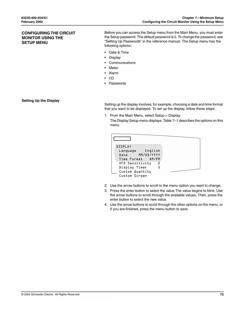
63230-400-204/A1 Chapter 7—Minimum SetupFebruary 2002 Configuring the Circuit Monitor Using the Setup Menu
© 2002 Schneider Electric All Rights Reserved
CONFIGURING THE CIRCUIT MONITOR USING THE SETUP MENU
Setting Up the Display
Before you can access the Setup menu from the Main Menu, you must enter the Setup password. The default password is 0. To change the password, see “Setting Up Passwords” in the reference manual. The Setup menu has the following options:
• Date & Time• Display
• Communications• Meter• Alarm
• I/O• Passwords
Setting up the display involves, for example, choosing a date and time format that you want to be displayed. To set up the display, follow these steps:
1. From the Main Menu, select Setup > Display. The Display Setup menu displays. Table 7–1 describes the options on this menu.
2. Use the arrow buttons to scroll to the menu option you want to change. 3. Press the enter button to select the value.The value begins to blink. Use
the arrow buttons to scroll through the available values. Then, press the enter button to select the new value.
4. Use the arrow buttons to scroll through the other options on the menu, or if you are finished, press the menu button to save.
DISPLAYLanguage EnglishDate MM/DD/YYYYTime Format AM/PMVFD Sensitivity 2Display Timer 5Custom QuantityCustom Screen
73

Chapter 7—Minimum Setup 63230-400-204/A1Configuring the Circuit Monitor Using The Setup Menu February 2002
74
Table 7–1: Factory Defaults for the Display Se
Option Available Values
Language EnglishFrancaisEspanol
Date MM/DD/YYYYYYYY/MM/DDDD/MM/YYYY
Time Format 2400hr AM/PM
VFD Sensitivity Off1 = 0–6 ft (0–15 m)2 = 0–12 ft (0–31 m)3 = 0–20 ft (0–51 m)
Display Timer 1, 5, 10, or 15 minutes
Custom Quantity Creating custom quantitiefeature, see “Creating Cu
Custom Screen Creating custom screensfeature, see “Creating Cu
Setting Up the Communications
Setting the Device Address
The Communications menu lets you set up the following communications:
• RS-485 communications for daisy-chain communication of the circuit monitor and other RS-485 devices.
• Infrared Port communications between the circuit monitor and a laptop computer (available only on the VFD display).
• Ethernet Options for Ethernet communications between the circuit monitor and your Ethernet network when an Ethernet Communications Card (ECC21) is present.
Each of these options is described in the sections that follow.
Each POWERLOGIC device on a communications link must have a unique device address. The term communications link refers to 1–32 POWERLOGIC compatible devices daisy-chained to a single communications port. By networking groups of devices, POWERLOGIC systems can support a virtually unlimited number of devices.
ttings
Selection Description Default
Language used by the display. English
Data format for all date-related values of the circuit monitor.
MM/DD/YYYY
Time format can be 24-hour military time or 12-hour clock with AM and PM.
2400hr
Sensitivity value for the proximity sensor (for the VFD display only).
2
Number of minutes the display remains illuminated after inactivity.
5
s is an advanced feature that is not required for basic setup. To learn more about this stom Quantities to be Displayed” in the reference manual.
is an advanced feature that is not required for basic setup. To learn more about this stom Screens” in the circuit monitor reference manual 63230-400-207.
© 2002 Schneider Electric All Rights Reserved

63230-400-204/A1 Chapter 7—Minimum SetupFebruary 2002 Configuring the Circuit Monitor Using The Setup Menu
© 2002 Schneider Electric All Rights Reserved
RS-485 and Infrared Port Communications Setup
To set up RS-485 or the infrared port communications, set the address, baud rate, and parity. Follow these steps:
1. From the Main Menu, select Setup > Communications. The Communications Setup screen displays.
NOTE: You can set up infrared communications only if the circuit monitor is equipped with a VFD display. Also, you can set up Ethernet communications only if the circuit monitor is equipped with an ECC card.
2. From the Comms Setup menu, select the type of communications that you are using. Depending on what you select, the screen for that communications setup displays, as shown below. Table 7–2 on page 76 describes the options on this menu.
3. Use the arrow buttons to scroll to the menu option you want to change. 4. Press the enter button to select the value.The value begins to blink. Use
the arrow buttons to scroll through the available values. Then, press the enter button to select the new value.
5. Use the arrow buttons to scroll through the other options on the menu, or if you are finished, press the menu button to save.
COMMUNICATIONSRS-485Infrared Port
INFRARED PORTProtocol ModbusAddress 1Baud Rate 9600Parity EvenRedirect Disabled
RS-485Protocol ModbusAddress 1Baud Rate 9600Parity EvenMode SlaveTimeout (sec) 2
75
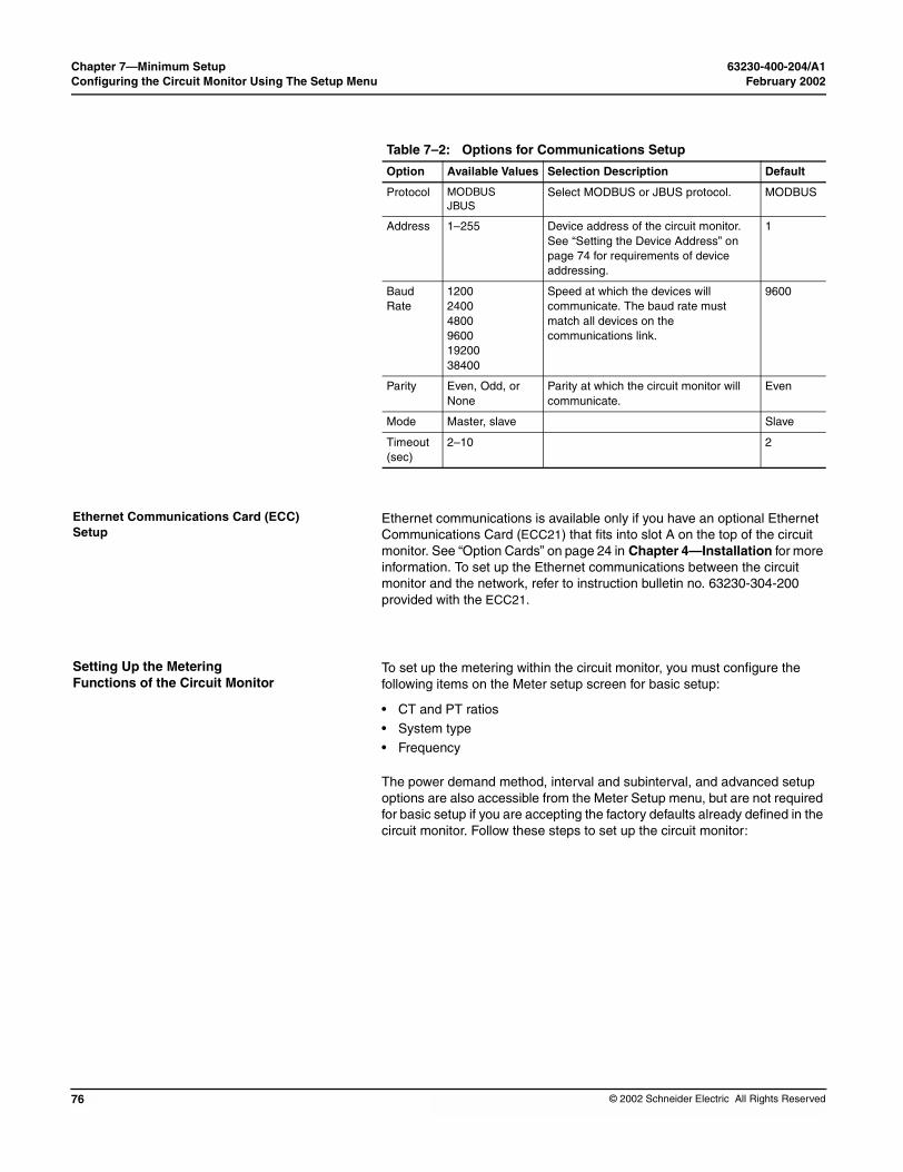
Chapter 7—Minimum Setup 63230-400-204/A1Configuring the Circuit Monitor Using The Setup Menu February 2002
76
Ethernet Communications Card (ECC) Setup
Setting Up the Metering Functions of the Circuit Monitor
Ethernet communications is available only if you have an optional Ethernet Communications Card (ECC21) that fits into slot A on the top of the circuit monitor. See “Option Cards” on page 24 in Chapter 4—Installation for more information. To set up the Ethernet communications between the circuit monitor and the network, refer to instruction bulletin no. 63230-304-200 provided with the ECC21.
To set up the metering within the circuit monitor, you must configure the following items on the Meter setup screen for basic setup:
• CT and PT ratios• System type• Frequency
The power demand method, interval and subinterval, and advanced setup options are also accessible from the Meter Setup menu, but are not required for basic setup if you are accepting the factory defaults already defined in the circuit monitor. Follow these steps to set up the circuit monitor:
Table 7–2: Options for Communications Setup
Option Available Values Selection Description Default
Protocol MODBUSJBUS
Select MODBUS or JBUS protocol. MODBUS
Address 1–255 Device address of the circuit monitor. See “Setting the Device Address” on page 74 for requirements of device addressing.
1
Baud Rate
12002400480096001920038400
Speed at which the devices will communicate. The baud rate must match all devices on the communications link.
9600
Parity Even, Odd, or None
Parity at which the circuit monitor will communicate.
Even
Mode Master, slave Slave
Timeout (sec)
2–10 2
© 2002 Schneider Electric All Rights Reserved

63230-400-204/A1 Chapter 7—Minimum SetupFebruary 2002 Configuring the Circuit Monitor Using The Setup Menu
© 2002 Schneider Electric All Rights Reserved
1. From the Main Menu, select Setup > Meter.
The Meter setup screen displays. Table 7–3 describes the options on this menu.
2. Use the arrow buttons to scroll to the menu option you want to change.
3. Press the enter button to select the value. The value begins to blink. Use the arrow buttons to scroll through the available values. Then, press the enter button to select the new value.
4. Use the arrow buttons to scroll through the other options on the menu, or if you are finished, press the menu button to save.
Required for basic setup
METERØ CT Primary 5Ø CT Secondary 5N CT Primary 5N CT Secondary 5PT Pri Scale x1PT Primary 120PT Secondary 120Sys Type 3Ø4W3CTFrequency (Hz) 60Pwr Dmd Meth SlidePwr Dmd Int 15Pwr Dmd Sub Int 1Advanced
77

Chapter 7—Minimum Setup 63230-400-204/A1Configuring the Circuit Monitor Using The Setup Menu February 2002
78
Table 7–3: Options for Meter Setup
Option Available Values Selection D
CT Primary 1–32,767 Set the ratinratings: one
CT Secondary 1 or 5 Set the ratin
PT Pri Scale x1x10x100No PT
Set the valuethan 32,767.number by 1For a direct-
PT Primary 1–32,767 Set the ratin
PT Secondary 100110115120
Set the ratin
Sys Type 3Ø3W2CT3Ø3W3CT3Ø4W3CT3Ø4W4CT3Ø4W3CT2PT3Ø4W4CT2PT
3Ø3W2CT is3Ø3W3CT is3Ø4W3CT is3Ø4W4CT is3Ø4W3CT2P3Ø4W4CT2PSet the systeconnection. types.
Frequency (Hz) 50, 60, or 400 Hz Frequency o
Pwr Dmd Meth Select the power demand calculaaverage demand of real power. Sa detailed description.Slide—Sliding Block DemandSlave—Slave Block DemandTherm—Thermal DemandRComms—Command-SynchronComms—Command-SynchronizRInput—Input-Synchronized RolInput—Input-Synchronized BlockRClock—Clock-Synchronized RoClock—Clock-Synchronized BlocRBlock—Rolling Block DemandBlock—Fixed Block DemandIncEngy—Synch to Incremental E
Pwr Dmd Int 1–60 Power demacalculates th
Pwr Dmd Sub Interval 1–60 Power demademand calcaccept a sub
Advanced See “Advanced Meter Setup” in t
escription Default
g for the CT primary. The circuit monitor supports two primary CT for the phase CTs and the other for the neutral CT.
5
g for the CT secondaries. 5
to which the PT Primary is to be scaled if the PT Primary is larger For example, setting the scale to x10 multiplies the PT Primary 0.current installation, select “No PT.”
x1
g for the PT primary. 120
g for the PT secondaries. 120
system type 30 system type 31 system type 40 system type 41T is system type 42T is system type 43m type. A system type code is assigned to each type of system
See Table 5–2 on page 33 for a description of system connection
3Ø4W3CT (40)
f the system. 60
tion method. The circuit monitor supports several methods to calculate ee “Demand Power Calculation Methods” in the reference manual for
ized Rolling Block Demanded Block Demandling Block Demand Demandlling Block Demandk Demand
nergy Interval
Slide
nd interval—set the time in minutes in which the circuit monitor e demand.
15
nd subinterval—period of time within the demand interval in which the ulation is updated. Set the subinterval only for methods that will interval. The subinterval must be evenly divisible into the interval.
N/A
he reference manual for more information.
© 2002 Schneider Electric All Rights Reserved

63230-400-204/A1 Chapter 8—TroubleshootingFebruary 2002 Chapter Contents
© 2002 Schneider Electric All Rights Reserved
CHAPTER 8—TROUBLESHOOTING
CHAPTER CONTENTS
CHAPTER CONTENTS . . . . . . . . . . . . . . . . . . . . . . . . . . . . . . . . . . . . . . 79GETTING TECHNICAL SUPPORT . . . . . . . . . . . . . . . . . . . . . . . . . . . . . 81
TROUBLESHOOTING . . . . . . . . . . . . . . . . . . . . . . . . . . . . . . . . . . . . . . . 82
This chapter describes information related to troubleshooting your circuit monitor.
79

Chapter 8—Troubleshooting 63230-400-204/A1Chapter Contents February 2002
80
The circuit monitor does not require regular maintenance, nor does it contain any user-serviceable parts. If the circuit monitor requires service, contact your local sales representative. Do not open the circuit monitor. Opening the circuit monitor voids the warranty.
HAZARD OF ELECTRIC SHOCK, BURN, OR EXPLOSION
Do not attempt to service the circuit monitor. CT and PT inputs may contain hazardous currents and voltages. Only authorized service personnel from the manufacturer should service the circuit monitor.
Failure to follow this instruction will result in death or serious injury.
DANGER
HAZARD OF EQUIPMENT DAMAGE
Do not perform a Dielectric (Hi-Pot) or Megger test on the circuit monitor. High voltage testing of the circuit monitor may damage the unit. Before performing Hi-Pot or Megger testing on any equipment in which the circuit monitor is installed, disconnect all input and output wires to the circuit monitor.
Failure to follow this instruction can result in injury or equipment damage.
CAUTION
© 2002 Schneider Electric All Rights Reserved

63230-400-204/A1 Chapter 8—TroubleshootingFebruary 2002 Getting Technical Support
© 2002 Schneider Electric All Rights Reserved
GETTING TECHNICAL SUPPORT
Please refer to the following Technical Support Contacts by country.Belgium / China / France /Italy / Northern & Eastern Europe/ Republic of South Africa:
POWERLOGIC System Technical SupportTel: +33 (0)4 76 39 41 55 Fax: +33 (0)4 76 39 40 72
Schneider Electric Centre M4 - MEYLAN 38240 FRANCE
North, Central & South America / Ireland / UK / Spain / Asia-Pacific (except China):
Power Management Operation Technical Support Schneider Electric 295 Tech Park Dr, Suite 100 LaVergne, TN USA 37086
Tel: (615) 287-3400 Fax: (615) 287-3404 e-mail: [email protected] www.powerlogic.com
For all other countries:
POWERLOGIC System Technical Support Tel: +33 (0)4 76 39 41 55 Fax: +33 (0)4 76 39 40 72
Schneider Electric Centre M4 - MEYLAN 38240 FRANCE
81

Chapter 8—Troubleshooting 63230-400-204/A1Troubleshooting February 2002
82
TROUBLESHOOTING
The information in Table 8–1 on page 83 describes potential problems and their possible causes. It also describes checks you can perform or possible solutions for each. After referring to this table, if you cannot resolve the problem, contact the your local Square D/Schneider Electric sales representative for assistance.HAZARD OF ELECTRIC SHOCK, BURN, OR EXPLOSION
• This equipment must be installed and serviced only by qualified personnel.
• Qualified persons performing diagnostics or troubleshooting that require electrical conductors to be energized must comply with NFPA 70 E - Standard for Electrical Safety Requirements for Employee Workplaces and OSHA Standards - 29 CFR Part 1910 Subpart S - Electrical.
• Carefully inspect the work area for tools and objects that may have been left inside the equipment.
• Use caution while removing or installing panels so that they do not extend into the energized bus; avoid handling the panels, which could cause personal injury.
Failure to follow these instructions will result in death or serious injury.
DANGER
© 2002 Schneider Electric All Rights Reserved

63230-400-204/A1 Chapter 8—TroubleshootingFebruary 2002 Troubleshooting
© 2002 Schneider Electric All Rights Reserved
Table 8–1: Troubleshooting
Potential Problem Possible Cause
The red maintenance LED is illuminated on the circuit monitor.
When the red mainteindicates a potential problem in the circui
The green control power LED is not illuminated on the circuit monitor.
The circuit monitor isnecessary power.
The display is blank after applying control power to the circuit monitor.
The display is not repower or communicamonitor.
The data being displayed is inaccurate or not what you expect.
Circuit monitor is gro
Incorrect setup value
Incorrect voltage inp
Circuit monitor is wir
Cannot communicate with circuit monitor from a remote personal computer.
Circuit monitor addre
Circuit monitor baud
Communications lineconnected.
Communications lineterminated.
Incorrect route state
Possible Solution
nance LED is illuminated, it hardware or firmware t monitor.
When the red maintenance LED is illuminated, “Maintenance LED” is added to the menu under “Diagnostics.” Error messages display to indicate the reason the LED is illuminated. Note these error messages and call Tech Support or contact your local sales representative for assistance.
not receiving the Verify that the circuit monitor line (L) and neutral (N) terminals (terminals 25 and 27) are receiving the necessary power.
ceiving the necessary tions signal from the circuit
Verify that the display cable is properly inserted into the connectors on the display and the circuit monitor.
unded incorrectly. Verify that the circuit monitor is grounded as described in “Grounding the Circuit Monitor” on page 49.
s. Check that the correct values have been entered for circuit monitor setup parameters (CT and PT ratings, System Type, Nominal Frequency, and so on). See “Setting Up the Metering Functions of the Circuit Monitor” on page 76 for setup instructions.
uts. Check circuit monitor voltage input terminals (9, 10, 11,12) to verify that adequate voltage is present.
ed improperly. Check that all CTs and PTs are connected correctly (proper polarity is observed) and that they are energized. Check shorting terminals. See “Wiring CTs, PTs, and Control Power to the Circuit Monitor” on page 33 for wiring diagrams. Initiate a wiring check from the circuit monitor display.
ss is incorrect. Check to see that the circuit monitor is correctly addressed. See “RS-485 and Infrared Port Communications Setup” on page 75 for instructions.
rate is incorrect. Verify that the baud rate of the circuit monitor matches the baud rate of all other devices on its communications link. See “RS-485 and Infrared Port Communications Setup” on page 75 for instructions.
s are improperly Verify the circuit monitor communications connections. Refer to Chapter 6—Communications Connections for instructions.
s are improperly Check to see that a multipoint communications terminator is properly installed. See “Terminating the Communications Link” on page 62 for instructions.
ment to circuit monitor. Check the route statement. Refer to the SMS online help for instructions on defining route statements.
83

Chapter 8—Troubleshooting 63230-400-204/A1Troubleshooting February 2002
84
© 2002 Schneider Electric All Rights Reserved
63230-400-204/A1 SpecificationsFebruary 2002
© 2002 Schneider Electric All Rights Reserved
Table A–1: SpecificationMETERING SPECIFICATIONCurrent Inputs (Each Chann
Current RangeNominal Current
Voltage Inputs (Each ChannVoltage RangeNominal Voltage (typical)
Frequency RangeHarmonic Response—Phase
Frequency 45–67 HzFrequency 350–450 Hz
Data Update Rate
Accuracy ➀Current (measured) ➁
Phase Amperes and Neu
Voltage
PowerReal, Reactive, and App
True Power FactorEnergy and DemandFrequency
50/60Hz400 Hz
Time of Day Clock/CalendaMETERING INPUT ELECTRICCurrent Inputs
NominalMetering Over-rangeOvercurrent Withstand
Input ImpedanceBurden
Voltage Inputs➃
Nominal Full ScaleMetering Over-rangeInput ImpedanceMeasurement Category➄
➀ Based on 1-second update ra
➁ Any CT secondary currents le
➂ If higher precision is required,
➃ Any voltage input to the meter
➄ Measurement category III is fo
APPENDIX A—SPECIFICATIONS
This appendix contains specifications for the circuit monitor and display.
sSel)
0–10 A ac5 A ac
el)0–600 Vac Line to Line, 347 Line to Neutral120 Vac45–67 Hz, 350–450 Hz
Voltages and Currents63rd Harmonic7th HarmonicApproximately 1-second update of all real-time readings for demand and energy calculations.
tral Amperes ± (0.075% of reading + 0.025% full scale)
Full scale = 10 A. Add |0.006% (Temperature [°C] - 25)| to the upper limit error for temperatures below 25°C.± (0.075% of reading + 0.025% full scale) Full scale = 600 V. Add 0.001% (Temperature [°C]) to the upper limit error for temperatures above 50°C.
arent Power ± (0.15% of reading + 0.025% full scale)Full scale = 120 V x 10 A. Add |0.006% (Temperature [°C])| to the upper limit error for temperatures below 25°C. ±0.002 from 0.500 leading to 0.500 laggingANSI C12.20 0.5 Class, IEC 60687 Class 0.5S ±0.01 Hz at 45–67 Hz±0.10 Hz at 350–450 Hz
r (at 25°C) ➂ Less than ±1.5 seconds in 24 hours (1 ms resolution)AL SPECIFICATIONS
5.0 A rms100% (10 A maximum)15 A rms Continuous50 A rms 10 seconds in 1 hour500 A rms 1 second in 1 hourLess than 0.1 OhmLess than 0.15 VA
347 Vac Line to Neutral, 600 Line to Line50% Greater than 2 MegohmIII (IEC 61010)
te.
ss than 5 mA are reported as zero.
see “Digital Inputs” in the reference manual for more information.
that is below 1.0 V is reported as zero.
r measurements performed in the building installation.
85

Appendix A—Specifications 63230-400-204/A1February 2002
86
CONTROL POWER INPUT S120/240 Vac Nominal
Operating Input RangeBurden, maximumFrequency RangeIsolationRide-through on Power Los
125/250 Vdc NominalOperating Input RangeBurdenIsolationRide-through on Power Los
Mains Supply Voltage FluctuaENVIRONMENTAL SPECIFICOperating Temperature
Meter and Optional Module
Remote Display
Storage TemperatureMeter and Optional ModuleRemote Display
Relative HumidityPollution DegreeInstallation Category
Altitude RangePhysical SpecificationsWeight (approximate, without DimensionsREGULATORY/STANDARDSEmissions Radiated
ConductedHarmonicsFlicker
Immunity ESD
RadiatedEFTSurgesConductedMagnetic FieldVoltage Dips
Accuracy
Table A–1: Specification
➀ Based on 1-second update ra
➁ Any CT secondary currents le
➂ If higher precision is required,
➃ Any voltage input to the meter
➄ Measurement category III is fo
PECIFICATIONS
90–305 Vac27 VA45–67 Hz, 350–450 Hz2300 V, 1 minute
s 99 ms at 120 Vac
100–300 Vdc16 W maximum3250 Vdc, 1 minute
s 75 ms at 125 Vdctions not to exceed ±10%ATIONS
s –25° to +70°C maximum May require 5°C derating when using optional card.(See information about operating temperature of the circuit monitor in “Mounting” on page 20.)VFD model is –20 to +70°CLCD model is –20 to +60°C
s –40 to +85°C VFD model is –40 to +85°CLCD model is –30 to +80°C5–95% (non-condensing) at 40°C2 (IEC 1010-1)III (IEC 1010-1)Category II when directly connected to mains above 300 V.0 to 3,048 m (10,000 ft)
add-on modules) 2.4 lb (1.1 kg)See “Dimensions” on page 14.
COMPLIANCE FCC Part 15 Class A, EN55011FCC Part 15 Class A, EN55011IEC 1000-3-2IEC 1000-3-3IEC 61000-6-2IEC 1000-4-2 Level 3IEC 1000-4-3 Level 3IEC 1000-4-4 Level 3IEC 1000-4-5 Level 3IEC 1000-4-6 Level 3IEC 1000-4-8 Level 3IEC 1000-4-11ANSI C12.20 Class 0.5 and IEC 60687 Class 0.5S
s
te.
ss than 5 mA are reported as zero.
see “Digital Inputs” in the reference manual for more information.
that is below 1.0 V is reported as zero.
r measurements performed in the building installation.
© 2002 Schneider Electric All Rights Reserved

63230-400-204/A1 SpecificationsFebruary 2002
© 2002 Schneider Electric All Rights Reserved
Product StandardsUSACanadaEurope
KYZ SPECIFICATIONSLoad voltageLoad current
ON resistanceLeakage current Turn ON/OFF timeInput or output isolation
Table A–1: Specification
➀ Based on 1-second update ra
➁ Any CT secondary currents le
➂ If higher precision is required,
➃ Any voltage input to the meter
➄ Measurement category III is fo
UL 508cUL508CE per low voltage directive EN 61010
up to 240 Vac or 300 Vdc maximum100 mA maximum at 25°CDerate load current 0.56 mA/°C above 25°C.35 ohms maximum0.03 µA (typical)3 ms3750 V rms
s
te.
ss than 5 mA are reported as zero.
see “Digital Inputs” in the reference manual for more information.
that is below 1.0 V is reported as zero.
r measurements performed in the building installation.
87

Appendix A—Specifications 63230-400-204/A1February 2002
88
© 2002 Schneider Electric All Rights Reserved
63230-400-204/A1 Appendix B—Cable PinoutsFebruary 2002
© 2002 Schneider Electric All Rights Reserved
APPENDIX B—CABLE PINOUTS
CAB-107(10-ft [3 m])
RX+ (20) GreenTX– (23) Black
TX+ (22) Red
(24) Shield
RX– (21) White23456789
1
RS-485Connector on
Circuit Monitor Male DConn
+12 V GND1
— — 2
TX RX 3
RX TX 4
— — 5
GND +126
RJ-12 Display Cab
This appendix contains pinouts for circuit monitor and display connections.
Figure B–1: Cable Pinouts
B-9 ector
FemaleDB-9
Connector Leads with
Spade Lugs
CAB-108(2-ft [.6 m])
23456789
1
5678
Shield—Shield
TXB—GreenTXA—White
RXA—BlackRXB—Red
1
2
3
4
5
V 6
50 ft (15 m) max. cable length RJ-12 6-position connector 4-wire, 26 AWG (0.1288 mm2) cable
le
89

Appendix B—Cable Pinouts 63230-400-204/A1February 2002
90
© 2002 Schneider Electric All Rights Reserved
63230-400-204/A1 GlossaryFebruary 2002
© 2002 Schneider Electric All R
GLOSSARY
accumulated energy—energy can accumulates in either signed or unsigned (absolute) mode. In signed mode, the direction of power flow is considered and the accumulated energy magnitude may increase and decrease. In absolute mode, energy accumulates as a positive regardless of the power flow direction.
address—see device address. See also Ethernet address.
ANSI—American National Standards Institute.
baud rate—specifies how fast data is transmitted across a network port.
block interval demand— power demand calculation method for a block of time and includes three ways to apply calculating to that block of time using the sliding block, fixed block, or rolling block method.
coincident readings—two readings that are recorded at the same time.
command interface—used to issue commands such as reset commands and to manually operate relays contained in registers 8000–8149.
communications link—a chain of devices such as circuit monitors and power meters that are connected by a communications cable to a communications port.
conditional energy—energy accumulates only when a certain condition occurs.
control power—provides power to the circuit monitor.
control power transformer (CPT)—transformer to reduce control power voltage to the meter.
crest factor (CF)—crest factor of voltage or current is the ratio of peak values to rms values.
current transformer (CT)—current transformer for current inputs.
current unbalance—percentage difference between each phase voltage with respect to the average of all phase currents.
default—a value loaded into the circuit monitor at the factory that you can configure.
demand—average value of a quantity, such as power, over a specified interval of time.
ights Reserved
device address—defines where the circuit monitor (or other devices) reside in the power monitoring system.
displacement power factor (dPF)—cosine of the angle between the fundamental components of current and voltage, which represents the time lag between fundamental voltage and current.
Ethernet address—a unique number that identifies the device in the Ethernet network and is always written as combination of eleven numbers such as 199.186.195.23.
event—the occurrence of an alarm condition, such as Undervoltage Phase A, configured in the circuit monitor.
firmware—operating system within the circuit monitor
frequency—number of cycles in one second.
fundamental—value of voltage or current corresponding to the portion of the signal at the power frequency (50, 60, or 400 Hz).
generic demand profile—up to 10 quantities on which any of the demand calculations can be performed (thermal demand, block interval demand, or synchronized demand). Two generic demand profiles can be set up in the circuit monitor.
harmonic power—difference between total power and fundamental power. A negative value indicates harmonic power flow out of the load. A positive value indicates harmonic power flow into the load.
harmonics—the circuit monitor stores in registers the magnitude and angle of individual harmonics up to the 63rd harmonic. Distorted voltages and currents can be represented by a series of sinusoidal signals whose frequencies are multipliers of some fundamental frequency, such as 60 Hz.
holding register—register that holds the next value to be transmitted.
IEC—International Electrotechnical Commission
incremental energy—accumulates energy during a user-defined timed interval.
91

Glossary 63230-400-204/A1February 2002
92
K-factor—a numerical rating used to specify power transformers for non linear loads. It describes a transformer’s ability to serve nonlinear loads without exceeding rated temperature rise limits.
KYZ output—pulse output from a metering device where each pulse has a weight assigned to it which represents an amount of energy or other value.
LCD—liquid crystal display.
line-to-line voltages—measurement of the rms line-to-line voltages of the circuit.
line-to-neutral voltages—measurement of the rms line-to-neutral voltages of the circuit.
logging—recording data at user-defined intervals in the circuit monitor’s nonvolatile memory.
maximum value—highest value recorded of the instantaneous quantity such as Phase A Current, Phase A Voltage, etc., since the last reset of the minimums and maximums.
minimum value—lowest value recorded of the instantaneous quantity such as Phase A Current, Phase A Voltage, etc., since the last reset of the minimums and maximums.
nominal—typical or average.
onboard—refers to data stored in the circuit monitor.
option cards—optional, field-installable accessories for the circuit monitor that expand the I/O and Ethernet communications capabilities because they can be inserted into slots in the circuit monitor.
overvoltage—increase in effective voltage to greater than 110 percent for longer than one minute.
parity—refers to binary numbers sent over the communications link. An extra bit is added so that the number of ones in the binary number is either even or odd, depending on your configuration). Used to detect errors in the transmission of data.
partial interval demand—calculation of energy thus far in a present interval. Equal to energy accumulated thus far in the interval divided by the length of the complete interval.
peak demand current—highest demand current measured in amperes since the last reset of demand. See also peak value.
peak demand real power—highest demand real power measured since the last rest of demand.
peak demand voltage—highest demand voltage measured since the last reset of demand voltage. See also peak value.
peak demand—highest demand measured since the last reset of peak demand.
peak value—of voltage or current is the maximum or minimum crest value of a waveform.
phase currents (rms)—measurement in amperes of the rms current for each of the three phases of the circuit. See also peak value.
phase rotation—phase rotations refers to the order in which the instantaneous values of the voltages or currents of the system reach their maximum positive values. Two phase rotations are possible: A-B-C or A-C-B.
potential transformer (PT)—also known as a voltage transformer
power factor (PF)—true power factor is the ratio of real power to apparent power using the complete harmonic content of real and apparent power. Calculated by dividing watts by volt amperes. Power factor is the difference between the total power your utility delivers and the portion of total power that does useful work. Power factor is the degree to which voltage and current to a load are out of phase. See also displacement power factor.
predicted demand—the circuit monitor takes into account the energy consumption thus far in the present interval and the present rate of consumption to predict demand power at the end of the present interval.
quantity—a parameter that the circuit monitor can measure or calculate such as current, voltage, power factor, etc.
real power—calculation of the real power (3-phase total and per-phase real power calculated) to obtain kilowatts.
recloser sequence—a series of voltage sags caused by a utility breaker opening a number of consecutive times in an effort to clear a fault. See also sag/swell.
© 2002 Schneider Electric All Rights Reserved

63230-400-204/A1 GlossaryFebruary 2002
© 2002 Schneider Electric All R
rms—root mean square. Circuit monitors are true rms sensing devices. See also harmonics (rms).
sag/swell—fluctuation (decreasing or increasing) in voltage or current in the electrical system being monitored. See also, voltage sag and voltage swell.
scale factor—multipliers that the circuit monitor uses to make values fit into the register where information is stored.
SMS—see System Manager Software.
synchronized demand—demand intervals in the circuit monitor that can be synchronized with another device using an external pulse, a command sent over communications, or the circuit monitor’s internal real-time clock.
System Manager Software (SMS)—software designed by POWERLOGIC for use in evaluating power monitoring and control data.
system type—a unique code assigned to each type of system wiring configuration of the circuit monitor.
thermal demand—demand calculation based on thermal response.
TIF/IT—telephone influence factor used to assess the interference of power distribution circuits with audio communications circuits.
Total Harmonic Distortion (THD or thd)—indicates the degree to which the voltage or current signal is distorted in a circuit.
total power factor—see power factor.
transient—sudden change in the steady-state condition of voltage or current.
troubleshooting—evaluating and attempting to correct problems with the circuit monitor’s operation.
true power factor—see power factor.
undervoltage—decrease in effective voltage to less than 90% for longer than one minute.
VAR—volt ampere reactive.
VFD—vacuum fluorescent display.
voltage interruption—complete loss of power where no voltage remains in the circuit.
ights Reserved
voltage sag—a brief decrease in effective voltage lasting more than one minute.
voltage swell—increase in effective voltage for up to one minute in duration.
voltage transformer (VT)—see potential transformer.
voltage unbalance—percentage difference between each phase voltage with respect to the average of all phase voltages.
waveform capture—can be done for all current and voltage channels in the circuit monitor.
93

63230-400-204/A1 GlossaryFebruary 2002
© 2002 Schneider Electric All R
ights Reserved 94
63230-400-204/A1 IndexFebruary 2002
© 2002 Schneider Electric All R
INDEX
Aaccessoriesdigital I/O card 24display options 18Ethernet communications card 24
addressdevice address 83
alarm LED 19alarms
enabled 10preconfigured 9
Bbaud rate 83
setup 76buttons
on the display 70
CCAB-103 89CAB-104 89CAB-107 89CAB-108 89changing
date format of circuit monitor 74circuit monitor
accessories 3described 2description of parts 12–13dimensions 14factory defaults 9features 3grounding 49instrumentation summary 2mounting 15pinouts 89quick installation 7setup of minimum parameters 8specifications 85wiring 29
communicationscable lengths (2-wire) Modbus/Jbus 65cable lengths (4-wire) 62cable pinouts 89capabilities 55daisy-chaining devices 58first device on daisy chain 61MODBUS or JBUS 65problems with PC communication 83protocols 56RS-485 connection 57serial comms 57termination of last device 62
connectionscommunications 55system types 33to the circuit monitor 29wiring 29
cc
c
C
Dd
d
d
d
d
dd
d
EEeeE
E
Fff
Ggg
ights Reserved
ontacting technical support 81ontrast
adjusting contrast on display 70contrast button 19
ontrol powerconnections 47fusing recommendations 31transformer sizing 30wiring 33
T and PTsetting up ratios 76
ata logpreconfigured logs 9
emand calculation methodset up 78
evicedaisy-chaining communications 58
evice addressset up of 76
iagnosticsperforming wiring error test 51
igital I/O card 24imensions
for circuit monitor 14for display 20
isplayadjusting contrast 70cable pinouts 89changing values from 71comms connection 23description 19dimensions 20main menu overview 72mounting 20–22mounting procedure 21set up 73using the buttons 70
CC. see Ethernet communications cardnter button 19rror messages 53thernet communications card 68
connections 68set up 76
thernet Gatewayconnections 67
actory defaults 9requency
setup 76
etting technical support 81rounding
circuit monitor 48
95

63230-400-204/A1 IndexFebruary 2002
© 2002 Schneider Electric All R
Hhardware
described 12Hi-Pot testing 80
Iinfrared port 19
communications 74
KKYZ
wiring 50
LLCD display
description 19locking
locking revenue security 25logs
preconfigured 9
Mmaintenance
of circuit monitor 80red maintenance LED 83
MCI-101 converter kit 57megger testing 80menu button
using this button 19, 70menu options
main menu overview 72mounting
of circuit monitor 15
Nnetwork connections
using Ethernet Communications Card 67using Ethernet Gateway 67
Oon-board event logs
factory defaults 9operation
green control power LED 83of circuit monitor 69of display 70problems with the circuit monitor 83problems with the display 83
Ppinouts 89potential transformers 31power demand calculation method.
see demand calculation method 78preconfigured alarms and logs 9problems
see troubleshooting 82protocols 56proximity sensor 19PT Inputs
deriving control power from 47
Rr
rR
Ss
sss
s
s
S
ss
s
S
s
Tttt
t
t
Uu
VV
v
ights Reserved
evenuesecurity switch 25
oute statement 83S-485 communication 57
afety precautionsgeneral 5
ecurity button 27ecurity switch 25ensor.
see proximity sensor 19et up
communications 74CT and PT ratios 76demand calculation method 78device address 76infrared port communications 74
etupminimum setup parameters 8quick setup 8
MSusing SMS 3
pecifications 85tandards
CE compliance 32uspected errors
see wiring 53ystem Manager Software
see SMS.ystem type
set up 76supported types described 33
ampering lock 25echnical support 81ermination
2-wire MODBUS or JBUS 66last device 62use of MCT-485 terminator 64use of MCTAS-485 terminator 63
estingdielectric (hi-pot) test 80megger test 80wiring test 51
roubleshooting 83
tility sealinstalling 27
FD displaydescription 19
oltage transformers 31
96

63230-400-204/A1 IndexFebruary 2002
© 2002 Schneider Electric All R
Wwiring
control power 33CTs and PTs 33diagrams 35–50for CE compliance 32KYZ output 50MODBUS or JBUS 65procedure 34system connections 33test error messages 53troubleshooting 51, 83wire test 51
ights Reserved
97
63230-400-204/A1 IndexFebruary 2002
© 2002 Schneider Electric All R
ights Reserved 98

Schneider ElectricPower Management Operation TECHNICAL SUPPORT295 Tech Park Dr, Suite 100LaVergne, TN USA 37086Tel. : (615) 287-3400Fax : (615) 287-3404e-mail: [email protected]
Bulletin No. 63230-400-204/A1 February 2002 © 2002 Schneider Electric All Rights Reserved. Class 3020