instruction booklet ib157002en power factor controller blr ... · reach the target cos phi get...
TRANSCRIPT
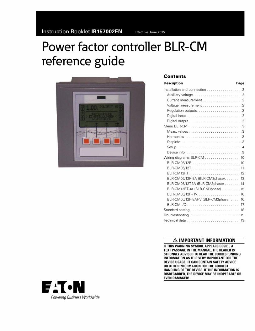
Instruction Booklet IB157002EN Effective June 2015
ContentsDescription Page
Installation and connection . . . . . . . . . . . . . . . . . . 2Auxiliary voltage . . . . . . . . . . . . . . . . . . . . . . . . . 2Current measurement . . . . . . . . . . . . . . . . . . . . 2Voltage measurement . . . . . . . . . . . . . . . . . . . . 2Regulation outputs . . . . . . . . . . . . . . . . . . . . . . . 2Digital input . . . . . . . . . . . . . . . . . . . . . . . . . . . . 2Digital output . . . . . . . . . . . . . . . . . . . . . . . . . . . 2
Menu BLR-CM . . . . . . . . . . . . . . . . . . . . . . . . . . . 3Meas. values . . . . . . . . . . . . . . . . . . . . . . . . . . . 3Harmonics . . . . . . . . . . . . . . . . . . . . . . . . . . . . . 3Stepinfo . . . . . . . . . . . . . . . . . . . . . . . . . . . . . . . 3Setup . . . . . . . . . . . . . . . . . . . . . . . . . . . . . . . . . 4Device info . . . . . . . . . . . . . . . . . . . . . . . . . . . . . 9
Wiring diagrams BLR-CM . . . . . . . . . . . . . . . . . . 10BLR-CM06/12R . . . . . . . . . . . . . . . . . . . . . . . . 10BLR-CM06/12T . . . . . . . . . . . . . . . . . . . . . . . . . 11BLR-CM12RT . . . . . . . . . . . . . . . . . . . . . . . . . . 12BLR-CM06/12R-3A (BLR-CM3phase) . . . . . . . . 13BLR-CM06/12T-3A (BLR-CM3phase) . . . . . . . . 14BLR-CM12RT-3A (BLR-CM3phase) . . . . . . . . . 15BLR-CM06/12R-HV . . . . . . . . . . . . . . . . . . . . . . 16BLR-CM06/12R-3AHV (BLR-CM3phase) . . . . . 16BLR-CM I/O . . . . . . . . . . . . . . . . . . . . . . . . . . . 17
Standard setting . . . . . . . . . . . . . . . . . . . . . . . . . 18Troubleshooting . . . . . . . . . . . . . . . . . . . . . . . . . 19Technical data . . . . . . . . . . . . . . . . . . . . . . . . . . . 19
m IMPORTANT INFORMATIONIF THIS WARNING SYMBOL APPEARS BESIDE A TEXT PASSAGE IN THE MANUAL, THE READER IS STRONGLY ADVISED TO READ THE CORRESPONDING INFORMATION AS IT IS VERY IMPORTANT FOR THE DEVICE USAGE! IT CAN CONTAIN SAFETY ADVICE OR OTHER INFORMATION FOR THE CORRECT HANDLING OF THE DEVICE. IF THE INFORMATION IS DISREGARDED, THE DEVICE MAY BE INOPERABLE OR EVEN DAMAGED!
Power factor controller BLR-CMreference guide
2
Instruction Booklet IB157002ENEffective June 2015
Power factor controller BLR-CM reference guide
EATON www.eaton.com
Installation and connection
m WARNING ONLY QUALIFIED STAFF IS ALLOWED TO PERFORM THE INSTALLATION. ALSO, ALL VALID RULES FROM THE GOVERNMENT MUST BE KEPT! BEFORE CONNECTING THE DEVICE, CHECK THAT ALL LINES ARE WITHOUT VOLTAGE AND SHORT CURRENT TRANSFORMER SECONDARY CIRCUIT.
1. Compare auxiliary voltage, measurement voltage, control voltage, frequency, and the current path of the device (see type label) with the data of the electricity network.
2. Assemble the relay in the switch panel with the two mounting clips. If the device is not fitting in the cutout, the small plastic bars on the side of the case can be removed with a knife.
3. Connect protective ground to the terminal link of the case.
4. Connect in accordance to the wiring diagram (pages 10–17).Pay special attention to the cross section size of the CT connections. An integrated voltage observation with regard to the auxiliary voltage in BLR-CM guarantees a safety disconnection of the capacitors in case of undervoltage. It must be ensured that auxiliary voltage is taken from the identical phase as control voltage for the contactors. Thus all switching elements are safely switched off in case of undervoltage.
5. The current path of the regulator is designed for current transformers x/5A and also for transformers x/1A. Remove short circuit links of the current transformer before commissioning.
Auxiliary voltage
With the BLR-CM, the measurement voltages and auxiliary voltages are separated. Because of this, it is necessary to connect the auxiliary voltage to separate terminals of the device (clamps La, Lb, and 0). The detailed connection depends on the device type and can be seen on the sticker at the back of the regulator.
Current measurement
For current measurement, transformer types x/1A or x/5A can be used. For connection, the clamps K(S1) and L(S2) have to be used. If desired, an additional ampere meter can be connected in series.
It is also possible to connect a summation current transformer to the BLR-CM. Pay attention that the correct factor is adjusted. This factor for a summation transformer can easily be calculated by adding the single transformer ratios (e.g., 1000A/5A + 1000A/5A + 1000A/5A = 200 + 200 + 200 = factor 600).
otee:N For three-phase current measurement, please ensure that the current inputs are connected to the correct phases in right hand rotating field.
Voltage measurement
The clamps Um1 and Um2 are for voltage measurement. This input is suitable for voltages between 50 V and 530 V. If the measurement voltage is out of the adjustable tolerance, all active steps are switched off and the regulation stops. In the circuit diagram, the standard connection with L1-N can be seen. There are also other connections possible. In case of using another connection type, the parameters on page 4 (Connection measurement and Phase compensation) have to be adapted. Details of the functions can be found in the referring chapters.
Regulation outputs
The power factor regulator is available with up to 12 outputs. Dependent on the regulator type, the outputs can be relay outputs or transistor outputs. The detailed regulator type can be found on the rear sticker either with the type description or the symbols of the output clamps. If you have the regulator type with mixed output steps, please pay attention that the clamp A1 is the common root for the relay outputs 1–6 and clamp A2 is the common root for the transistor outputs 7–12.
Relay outputs
The relay outputs of the power factor controller are designed for the direct connection to contactors. The relay outputs are potential-free with one common root.
Maximum breaking capacity 250 Vac / 5 A, maximum fuse 6 A.
Transistor outputs
The transistor outputs of the power factor controller are designed for the direct connection to thyristor switches. These open-collector outputs have one common root. To trigger a thyristor switch, connect (–) to the root and (+) directly to the thyristor switch.
Maximum breaking capacity 8–48 Vdc / 100 mA.
Alarm relay
For external contact, the regulator is equipped with an alarm relay M (potential-free change-over contact). The breaking capacity is 3 A / 250 Vac. The closing contact is connected to the clamps M and MS, the break contact is connected to the clamps M and MO. This contact is programmed as life-contact. In case of failure of the auxiliary voltage, this contact automatically closes. See circuit diagram on page 17.
Digital input
The power factor regulator has a digital input (clamps DI1 and DI2). This input is detected as active when there is a voltage between 50 and 250 Vac. The function of this input can be programmed in the menu “SETUP / ALARM / INPUT DI”. More details for the programming can be found in “ALARM” section. See circuit diagram on page 17.
Digital output
For external contact, the regulator BLR-CM is additionally equipped with a digital output (clamps DO1 and DO2). This output is a potential-free closing contact. The breaking capacity is 5 A / 250 Vac. The function of this output can be programmed in the menu “SETUP / ALARM”. More details for the programming can be found in “ALARM” section. See circuit diagram on page 17.
3
Instruction Booklet IB157002ENEffective June 2015
Power factor controller BLR-CM reference guide
EATON www.eaton.com
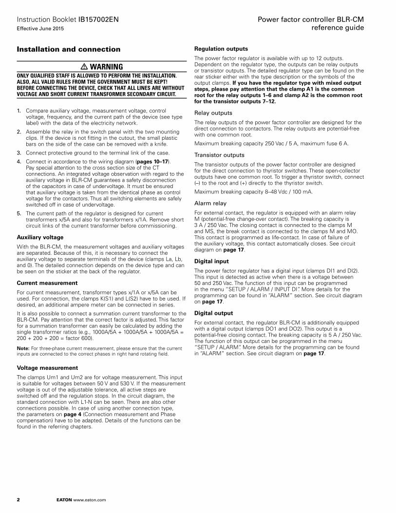
Menu BLR-CM Meas. values
In this submenu, measurement values of the regulator can be displayed in the bottom display area. The values can be selected with the ▲ / ▼ keys.
The following measurement values can be displayed:
Messung BLR-CM Messung BLR-CM3phase
ULL (voltage phase–phase)ULN (voltage phase–neutral)THD of voltageI (current)THD of currentP (total active power)Q (total reactive power)S (total apparent power)F (frequency)∆Q (lacking reactive power for reaching the adjusted target cos w)T (temperature at rear side of the device)WPI / WPE (counter active work import / export)WQI / WQC (counter reactive work inductive / capacitive)
ULL (voltage phase–phase)ULN (voltage phase–neutral)THD of voltageI1 /I2 / I3 (current)THD 1 / THD 2 / THD 3 of currentP1 / P1 / P1 (active power for each phase)Q1 / Q2 /Q3 (reactive power for each phase)S1 / S2 / S3 (apparent power for each phase)P (total active power)Q (total reactive power)S (total apparent power)∆Q1 (lacking reactive power for reaching target cos w L1)∆Q2 (lacking reactive power for reaching target cos w L2)∆Q3 (lacking reactive power for reaching target cos w L3)∆Q (total lacking reactive power)CP1 (cos phi L1 )CP2 (cos phi L2)CP3 (cos phi L3)Pf 1Pf 2
P = activePowerS apparentPower
Pf 3F (frequency)T (temperature at rear side of the device)
otee: N Counters can be reset by the means of the ▼ key (separately for active work and reactive work).
Harmonics
The BLR-CM continuously calculates the harmonics of the voltage and current with the Fourier transformation. The rating of the harmonics is done by EN 61000-2-4 up to the 30th harmonic order. The harmonics are displayed in percent and all refer to the TRMS value. After selecting the submenu, these values can be displayed separately for current and voltage (separate for even/odd harmonics) in the main display area. Switching between the different displays can be done by pushing the ▼ ▼ key. Scrolling in the list is possible by pushing the ▲ / ▼ keys. Every displayed value is related to the fundamental wave.
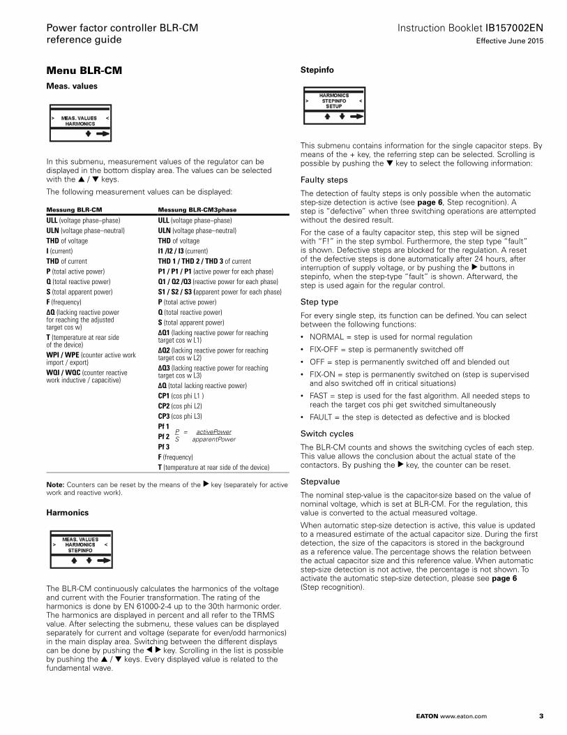
Stepinfo
This submenu contains information for the single capacitor steps. By means of the + key, the referring step can be selected. Scrolling is possible by pushing the ▼ key to select the following information:
Faulty steps
The detection of faulty steps is only possible when the automatic step-size detection is active (see page 6, Step recognition). A step is “defective” when three switching operations are attempted without the desired result.
For the case of a faulty capacitor step, this step will be signed with “F!” in the step symbol. Furthermore, the step type “fault” is shown. Defective steps are blocked for the regulation. A reset of the defective steps is done automatically after 24 hours, after interruption of supply voltage, or by pushing the ▼ buttons in stepinfo, when the step-type “fault” is shown. Afterward, the step is used again for the regular control.
Step type
For every single step, its function can be defined. You can select between the following functions:• NORMAL = step is used for normal regulation• FIX-OFF = step is permanently switched off• OFF = step is permanently switched off and blended out• FIX-ON = step is permanently switched on (step is supervised
and also switched off in critical situations)• FAST = step is used for the fast algorithm. All needed steps to
reach the target cos phi get switched simultaneously• FAULT = the step is detected as defective and is blocked
Switch cycles
The BLR-CM counts and shows the switching cycles of each step. This value allows the conclusion about the actual state of the contactors. By pushing the ▼ key, the counter can be reset.
Stepvalue
The nominal step-value is the capacitor-size based on the value of nominal voltage, which is set at BLR-CM. For the regulation, this value is converted to the actual measured voltage.
When automatic step-size detection is active, this value is updated to a measured estimate of the actual capacitor size. During the first detection, the size of the capacitors is stored in the background as a reference value. The percentage shows the relation between the actual capacitor size and this reference value. When automatic step-size detection is not active, the percentage is not shown. To activate the automatic step-size detection, please see page 6 (Step recognition).
4
Instruction Booklet IB157002ENEffective June 2015
Power factor controller BLR-CM reference guide
EATON www.eaton.com
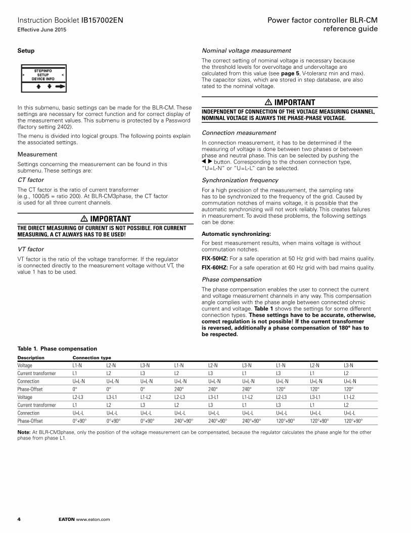
Setup
In this submenu, basic settings can be made for the BLR-CM. These settings are necessary for correct function and for correct display of the measurement values. This submenu is protected by a Password (factory setting 2402).
The menu is divided into logical groups. The following points explain the associated settings.
Measurement
Settings concerning the measurement can be found in this submenu. These settings are:
CT factor
The CT factor is the ratio of current transformer (e.g., 1000/5 = ratio 200). At BLR-CM3phase, the CT factor is used for all three current channels.
m IMPORTANT THE DIRECT MEASURING OF CURRENT IS NOT POSSIBLE. FOR CURRENT MEASURING, A CT ALWAYS HAS TO BE USED!
VT factor
VT factor is the ratio of the voltage transformer. If the regulator is connected directly to the measurement voltage without VT, the value 1 has to be used.
Nominal voltage measurement
The correct setting of nominal voltage is necessary because the threshold levels for overvoltage and undervoltage are calculated from this value (see page 5, V-toleranz min and max). The capacitor sizes, which are stored in step database, are also rated to the nominal voltage.
m IMPORTANT INDEPENDENT OF CONNECTION OF THE VOLTAGE MEASURING CHANNEL, NOMINAL VOLTAGE IS ALWAYS THE PHASE-PHASE VOLTAGE.
Connection measurement
In connection measurement, it has to be determined if the measuring of voltage is done between two phases or between phase and neutral phase. This can be selected by pushing the ▼ ▼ button. Corresponding to the chosen connection type, “U=L-N” or “U=L-L” can be selected.
Synchronization frequency
For a high precision of the measurement, the sampling rate has to be synchronized to the frequency of the grid. Caused by commutation notches of mains voltage, it is possible that the automatic synchronizing will not work reliably. This creates failures in measurement. To avoid these problems, the following settings can be done:
Automatic synchronizinge:
For best measurement results, when mains voltage is without commutation notches.
FIX-50HZe: For a safe operation at 50 Hz grid with bad mains quality.
FIX-60HZe: For a safe operation at 60 Hz grid with bad mains quality.
Phase compensation
The phase compensation enables the user to connect the current and voltage measurement channels in any way. This compensation angle complies with the phase angle between connected ohmic current and voltage. Table 1 shows the settings for some different connection types. These settings have to be accurate, otherwise, correct regulation is not possible! If the current transformer is reversed, additionally a phase compensation of 180° has to be respected.
Table 1. Phase compensation
Description Connection type
Voltage L1-N L2-N L3-N L1-N L2-N L3-N L1-N L2-N L3-NCurrent transformer L1 L2 L3 L2 L3 L1 L3 L1 L2Connection U=L-N U=L-N U=L-N U=L-N U=L-N U=L-N U=L-N U=L-N U=L-NPhase-Offset 0° 0° 0° 240° 240° 240° 120° 120° 120°Voltage L2-L3 L3-L1 L1-L2 L2-L3 L3-L1 L1-L2 L2-L3 L3-L1 L1-L2Current transformer L1 L2 L3 L2 L3 L1 L3 L1 L2Connection U=L-L U=L-L U=L-L U=L-L U=L-L U=L-L U=L-L U=L-L U=L-LPhase-Offset 0°+90° 0°+90° 0°+90° 240°+90° 240°+90° 240°+90° 120°+90° 120°+90° 120°+90°
otee: N At BLR-CM3phase, only the position of the voltage measurement can be compensated, because the regulator calculates the phase angle for the other phase from phase L1.
5
Instruction Booklet IB157002ENEffective June 2015
Power factor controller BLR-CM reference guide
EATON www.eaton.com
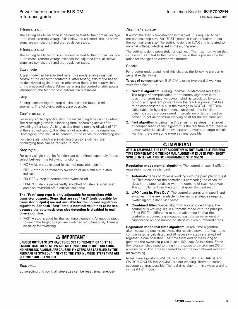
V-toleranz min
The setting has to be done in percent related to the nominal voltage. If the measurement voltage falls below the adjusted limit, all active steps are switched off and the regulation stops.
V-toleranz max
The setting has to be done in percent related to the nominal voltage. If the measurement voltage exceeds the adjusted limit, all active steps are switched off and the regulation stops.
Test mode
A test mode can be activated here. This mode enables manual control of the capacitor contactors. After testing, this mode has to be deactivated again, because otherwise there is no supervision of the measured values. When restarting the controller after power interruption, the test mode is automatically disabled.
Step
Settings concerning the step database can be found in this submenu. The following settings are possible:
Discharge time
For every single capacitor step, the discharging time can be defined. The discharging time is a blocking time, becoming active after switching off a step. As long as this time is running (display of “!” in the step indication), this step is not available for the regulation. Discharging time should be adapted to the capacitor discharging unit.
For step exits, which are switching thyristor switches, the discharging time can be reduced to zero.
Step type
For every single step, its function can be defined separately. You can select between the following functions:• NORMAL = step is used for normal regulation algorithm• OFF = step is permanently switched of an blend out in step
indication• FIX-OFF = step is permanently switched off• FIX-ON = step is permanently switched on (step is supervised
and also switched off in critical situations)
The “Fast” step type is only adjustable for controllers with transistor outputs. Steps that are set “Fast” (only possible for transistor outputs) are not available for the normal regulation algorithm. For each “Fast” step, a nominal value has to be set, because the automatic step size detection is disabled in real time algorithm.
• FAST = step is used for the real time algorithm. All needed steps to reach the target cos phi are switched simultaneously. There is no delay for switching
m IMPORTANT UNUSED OUTPUT STEPS HAVE TO BE SET TO “FIX-OFF” OR “OFF” TO ENSURE THAT THESE STEPS ARE NO LONGER USED FOR REGULATION. NO NEEDLESS ALARMS ARE CAUSED! FIX STEPS ARE LABELLED BY THE PERMANENT SYMBOL “!” NEXT TO THE STEP NUMBER. STEPS THAT ARE SET “OFF” ARE BLEND OUT.
Step reset
By selecting this point, all step sizes can be reset simultaneously.
Nominal step size
If automatic step size–detection is disabled, it is required to set the nominal step size. For “FAST” steps, it is also required to set the nominal step size. The setting is done in kVAR and is related to nominal voltage, which is set in measuring menu.
The setting is done separately for each exit. The maximum value that can be set is limited to the maximum value that is possible by the ratios for voltage and current transformer.
Control
For a better understanding of this chapter, the following are some general explanations:
Target of compensatione: BLR-CM is using two parallel working regulation algorithms.
1. Normal algorithm is using “normal” contactor-based steps. The target of compensation of the normal algorithm is to reach the target reactive power, which is calculated by target cos-phi and apparent power. From the reactive power that has to be compensated is built the average in SWITCH INTERVAL (adjustable). In hybrid compensation panels, the installed dynamic steps are considered in calculation of target reactive power, to get an optimum working point for the real time part.
2. Fast algorithm is using “fast” transient-free steps. The target of compensation of fast algorithm is the real time target reactive power, which is calculated by apparent power and target cos-phi. For this, there are some more settings possible.
m IMPORTANTAT BLR-CM3PHASE, THE FAST ALGORITHM IS NOT AVAILABLE. FOR REAL TIME COMPENSATION, THE NORMAL ALGORITHM IS USED WITH SHORT SWITCH INTERVAL AND FIX PROGRAMMED STEP SIZES!
Regulation mode normal algorithme: The controller uses 3 different regulation modes as standard:
1. Automatice: The controller is working with the principle of “Best Fit“. This means that the controller is comparing the capacitor sizes in the step database with the demand of reactive power. The controller will use the step that gives the best result.
2. LIFO “Last In, First Out”e: The controller starts with step 1 and switches in the next available higher number step, as required. Switching-off is done vice versa.
3. Combined filtere: Special algorithm for combined filters. The controller is working like in automatic mode with the principle “Best Fit”. The difference to automatic mode is, that the controller is connecting always at least the same amount of capacitance on odd numbered steps as even numbered steps.
Regulation mode real time algorithme: In real time algorithm after measuring one mains cycle, the reactive power that has to be compensated is calculated and all necessary steps are switched together in one operation. The time from end of measuring to generate the switching pulse is less 150 μsec. At this time, Eaton thyristor switches need to bring in the capacitors maximum 2/3 of a mains cycle. This time is needed to get the next allowed moment for switching.
In real time algorithm SWITCH INTERVAL, STEP EXCHANGE and SWITCH CYCLES BALANCING are not working. There are some separate settings possible. The real time algorithm is always working in “Best Fit” mode.

6
Instruction Booklet IB157002ENEffective June 2015
Power factor controller BLR-CM reference guide
EATON www.eaton.com
Sensitivity (switching threshold)e: The sensitivity is the switching threshold for switching-on or switching-off the capacitors in percent (%). The range of the sensitivity can be between 55% and 100%. (Factory setting is 60%. Due to this, the following explanations are using 60%.)
Sensitivity is used for checking:
1. The controller is checking with sensitivity, if a switching operation is necessary or if it’s possible. The controller is using for this the smallest connected step. If 60% of the power of the smallest step are needed, the pfc-relay is looking in the step database for a suitable step. At switching-off the controller is working vice versa. If at least 60% of the smallest step is overcompensated, the controller is looking for a step, which can be switched-off.
2. To avoid hunting, the controller is only switching steps, which are not overcompensating more than 40% (100%–60%). At switching-off, the regulator is looking for steps, which cause a maximum under compensation of 40% of the step size.
Step exchangee: This function is supporting automatic control and combined filter control algorithm to reach optimum results. If the controller detects that target-pf is not reached, it starts searching for a step that gives better results. If step exchange is active, the controller can replace an active step against a step that matches better, to reach the target.
Switch cycles balancinge: If this function is active, the controller is using for the next switching operation (from steps with the same or similar size) the step with the minimum number of switching cycles. Switching cycles of the steps are balanced by this. A balanced attrition of contactors and capacitors is assured by this.
Fast regulatione: For real time compensation, the controller has a second parallel working algorithm. This algorithm is used for all steps, which are set to step type “FAST” (see page 5 Step type). The fast algorithm has a reaction time of less 150 μsec and is switching all necessary steps in one switching operation. In this algorithm, switching time delay, switch cycles balancing and step exchange are not working. The fast algorithm is working in “Best-Fit” principle.
Settings concerning the control functions can be found in this submenu. These settings are possible:
COS PHI 1
This is the setting for target-cos phi 1. It will be valid during normal operation.
COS PHI 2
This is the setting for target-cos phi 2. It will be valid when a switch over is caused by the digital input or another programmable action.
Switch interval
The switch interval is the time delay between switching steps in regulation.
The switch interval has two different functions:
1. Protecting the contactors by reducing the number of switching cycles.
2. Building of the average of the reactive power in the time of the switch interval.
otee:N If regulation mode LIFO is selected, the minimum switching interval is 1 sec longer, as the longest discharging time. In HV-version, the minimum switching time delay is 8.7 sec.
Switch interval step exchange
For step exchange, standard switch interval is not used. There is a separate switch interval for step exchange. This is the delay-time between switching-off an active step and switching-in the next step to get a better power factor. Step exchange can be set active in menu on page 6.
Step recognition
With the ▼ ▼ key, step recognition can be chosen between “ON” and “OFF”.
“Step recognition OFF”e: Capacitor sizes must be programmed manually:
A. When there is fast oscillating load in the system, which causes problems of automatic step size detection.
B. When recognition of defective steps is not wanted.
C. When capacitor contactors are switching with a delay of more than 200 msec.
“Step recognition ON”e: Step sizes are detected and corrected automatically during normal operation. “Step recognition ON” is the factory setting, because it allows supervision of the capacitor sizes and gives alarms when there are failures. Step sizes that are programmed manually will be overwritten by step recognition.
Switch cycles balancing
With the ▼ ▼ key, switch cycles balancing can be chosen between “ON” and “OFF”. When this function is “ON”, the regulator balances the switch cycles of steps with the same or similar size, resulting in an equal attrition of the contactors and capacitors.
Switch cycles balancing %
Difference of similar step sizes in percent for switch cycles balancing.
Step exchange
With the ▼ ▼ key, step exchange can be chosen between “ON” and “OFF”. This function changes steps to reach target-pf more exactly.
Control sensitivity
Percentage of the sensitivity of regulation. Factory setting is 60%. This value can be set in a range between 55% and 100%.
Control
Three control modes can be selected:
AUTOMATICe: “Best Fit“
LIFOe: “Last in, first out“
otee:N For each step, it is checked separately, if switching makes sense. If the steps have different sizes, this can cause inaccuracy. Step recognition is working in this mode as well, when it is active. This can cause that steps are detected as defective and are not used for regulation anymore. These steps are skipped in this mode. If this is not accepted, the step recognition has to be set to “OFF” and the capacitor sizes have to be programmed manually.
Combi - Filtere: This setting assures that in combined filters the amount of connected reactive power with lower order harmonic tuning is at least as high as the amount of connected reactive power with higher order harmonic tuning.
otee:N The capacitors with higher degree of choking must be connected to the odd exits. The capacitors with smaller degree of choking must be connected to the even exits.

7
Instruction Booklet IB157002ENEffective June 2015
Power factor controller BLR-CM reference guide
EATON www.eaton.com
I < limit freeze steps
Yese: If current is detected as zero, the regulator is freezing all the steps until it can measure current again.
Noe: If current is detected as zero, the regulator is switching-off the capacitors step by step with intervals of 30 sec, to check for a broken cable until it can measure a current again.
The following only affect fast regulatione:
Fast control measuring break
Setting of a measuring break after a switching operation. This measuring break avoids errors caused by the reactions of the last switching operation.
This setting must be done carefully to avoid controller overshoot and instability.
Fast control maximum step size
Maximum capacitor power, which is allowed to switch in one switching operation. The controller is switching all necessary steps at the same time. If this is not allowed or if this causes unwanted reactions, then the maximum power that is switched in one cycle can be limited. The setting is done in kVAR.
With setting “0” (factory setting), the limit is not active.
Fast control average Q
Setting of the number of mains cycles, which are used to build the average of reactive power that needs to be compensated. This averaging process starts after the measuring break is finished (see page 7).
Fast control sync. Imp.
Yese: The trigger pulse for switching the thyristor-switches is synchronous to the zero-crossing of the mains voltage (rising sinusoid). This can cause a delay of the switching operation, which is less than one mains cycle.
Noe: The trigger pulse for switching the thyristor-switches is coming directly after finishing the measuring of one period + run time for the algorithm (some μsec).
Display
In this submenu, settings can be made according to the display. The following settings are possible:
Display
The following masks can be selected for the top display area by pushing the ▼ ▼ key. This masking is permanently displayed. After leaving this submenu, the setting is stored automatically. The following masks are displayable:
Cos , DI, M, DO: Display of power factor and status of inputs and outputs (• =inactive, • = active).
Cos , ∆Q: : Display of power factor and the lacking reactive power.
Cos , valid Target cos (1 or 2): Showing of power factor and of the chosen target power factor (e.g., tariff switching with digital input).
Contrast
The contrast of the LCD display can be adjusted by pushing the + / – keys. After exiting this submenu, the setting is stored automatically.
Password
By pushing the + / – keys, the password can be changed. Reaching the last digit, the new password is stored by pushing the ▼ key. To remove password protection, set the password to 0000.
8
Instruction Booklet IB157002ENEffective June 2015
Power factor controller BLR-CM reference guide
EATON www.eaton.com
Alarm
In the following chapter, all adjustable alarms including trigger are listed.
Alarm Description
Control alarm Trigger after 50x switching time not reaching the target cos phifQ > smallest step (over-/under compensation)
No current Trigger: I < sensitivityReaction: switch off steps to reach current flow
Step fault Trigger: Step size detection not possibleReaction: Alarm after 3 switching trials
Step warning Trigger: a) Step size falls below an adjustable %value relating to the first acquired step sizeb) Switch cycles exceeding the adjustable limit for switch cycles
COS PHI Trigger: The actual COS PHI is outside the adjustable range between c0.80 and i0.80. The delay time can be adjusted from 1s to 36000s.
Harmonics U Trigger: THD U exceeds the adjusted limit between 1% and 99.9% related to the fundamental wave
Harmonics I Trigger: THD I exceeds the adjusted limit between 1% and 99.9% related to the fundamental wave
Overload P Trigger: Amount of P exceeds the adjustable limit between 1 kW and 99.9 MW
Overload Q Trigger: Amount of Q exceeds the adjustable limit between 1 kVAR and 99.9 MVAR
P-export Trigger: Alarm will be triggered as soon as P-export is recognized
Temp1 / Temp2 Trigger: Ambient temperature exceeds the adjusted limitDI Input Trigger: Apply voltage to the DI inputOvercurrent Trigger: I > measurement range current channel
It is not possible to deactivate this alarm. The controller always generates a signal via the display and the M-relays
Over/undervoltage Trigger: U beyond the limit. This limit is adjustable under point V-toleranz min and V-toleranz max on page 5It’s not possible to deactivate this alarm. The control stops and the M-relays is activated.
Alarm events
M-Relayse: The M-Relay is a volt-free output. It can be used as anNO/NC contact. Maximum fuse 6 A, breaking capacity 250 Vac / 5 A.
Digital Oute: The digital output is a volt-free output. It can only be used as an NO contact. Maximum fuse 6 A, breaking capacity 250 Vac / 5 A.
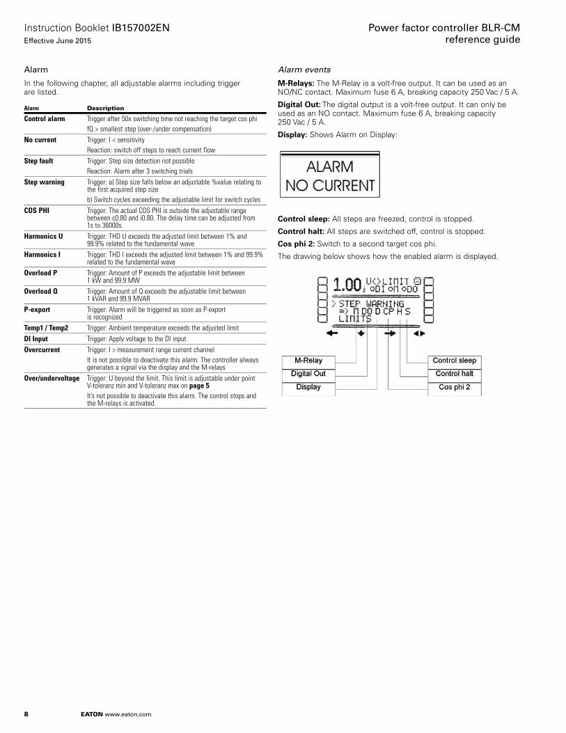
Displaye: Shows Alarm on Display:
Control sleepe: All steps are freezed, control is stopped.
Control halte: All steps are switched off, control is stopped.
Cos phi 2e: Switch to a second target cos phi.
The drawing below shows how the enabled alarm is displayed.

9
Instruction Booklet IB157002ENEffective June 2015
Power factor controller BLR-CM reference guide
EATON www.eaton.com
Manual
By selecting this submenu, the manual mode for the regulator is active. A valid measurement voltage is required. By pressing the + key, the referring step can be selected. Changing the switching state is possible by pushing the ▼ ▼ key. Manual switching is only possible with a valid measurement voltage. If there is a manual mode necessary without a valid measurement voltage, the test mode on page 5 has to be activated. After testing, this mode has to be deactivated again.
m IMPORTANTAFTER SWITCHING OFF AN ACTIVE STEP, THE DISCHARGING TIME IS ACTIVE. ONLY AFTER THIS TIME IS OVER THE STEP CAN BE SWITCHED ON MANUAL AGAIN. DURING THE MANUAL MODE, THE REGULATION FOR THE NOT MANUAL SWITCHED STEPS KEEPS ACTIVE! NEVERTHELESS THE MANUAL MODE SHOULD BE LEFT WHEN IT IS NOT NECESSARY ANY MORE! AFTER LEAVING THE MANUAL MODE, ALL STEPS SHALL BE SWITCHED OFF.
Modbus
This submenu is only enabled if the regulator is equipped with the Modbus interface. The following settings are possible:• Baud ratee: The baud rate can be selected by pushing the
▼ ▼ key. The valid range is between 1200 and 38400• Paritye: The parity can be selected by pushing the ▼ ▼ key. The
following settings are possible: 8E1 (8 data bits/even parity/1 stop bit), 8O1 (8 data bits/odd parity/1 stop bit) and 8N2 (8 data bits/no parity/2 stop bits)
• Addresse: By pushing the ▼ key, it is possible to enter the slave address (slave ID). The valid range is between 1 and 247
The settings for baud rate and parity must be the same for all bus devices. The address must be unique for each device.
Reset
This submenu resets the device to factory settings.
Configuration
In this submenu, the basic configuration can be changed. This should be done only after consultation with Eaton.
Device info
Device typee: e.g., BLR-CM
Software versione: z. B. VER 02.02.00
FLGe: MB
10
Instruction Booklet IB157002ENEffective June 2015
Power factor controller BLR-CM reference guide
EATON www.eaton.com
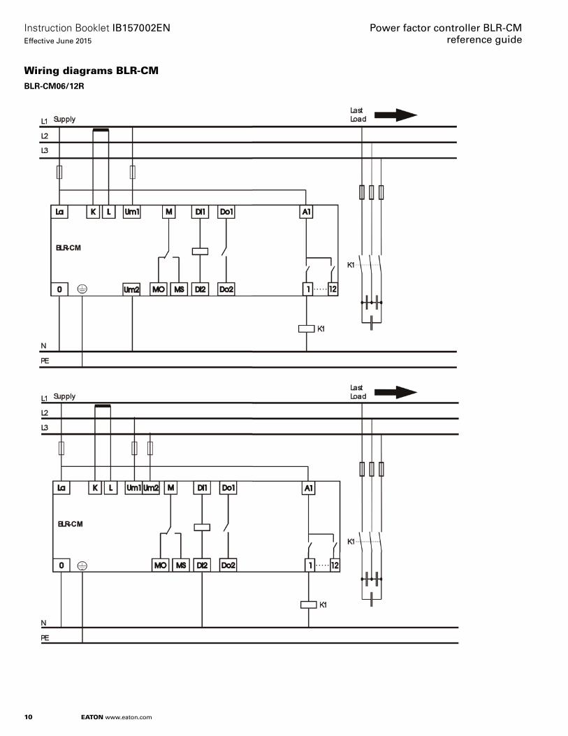
Wiring diagrams BLR-CM BLR-CM06/12R

11
Instruction Booklet IB157002ENEffective June 2015
Power factor controller BLR-CM reference guide
EATON www.eaton.com
BLR-CM06/12T

12
Instruction Booklet IB157002ENEffective June 2015
Power factor controller BLR-CM reference guide
EATON www.eaton.com
BLR-CM12RT

13
Instruction Booklet IB157002ENEffective June 2015
Power factor controller BLR-CM reference guide
EATON www.eaton.com
BLR-CM06/12R-3A (BLR-CM3phase)

14
Instruction Booklet IB157002ENEffective June 2015
Power factor controller BLR-CM reference guide
EATON www.eaton.com
BLR-CM06/12T-3A (BLR-CM3phase)
15
Instruction Booklet IB157002ENEffective June 2015
Power factor controller BLR-CM reference guide
EATON www.eaton.com
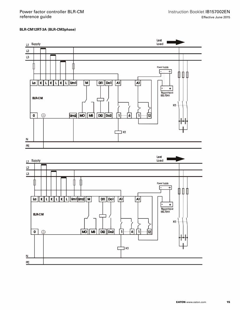
BLR-CM12RT-3A (BLR-CM3phase)

16
Instruction Booklet IB157002ENEffective June 2015
Power factor controller BLR-CM reference guide
EATON www.eaton.com
BLR-CM06/12R-HV
BLR-CM06/12R-3AHV (BLR-CM3phase)

17
Instruction Booklet IB157002ENEffective June 2015
Power factor controller BLR-CM reference guide
EATON www.eaton.com
BLR-CM I/O
The M-Relays can beprogrammed as reactionfor each Alarm
The DO can beprogrammed as reactionfor each Alarm
In factory settings, it isprogrammed as fan controlTrigger 25°
Programmable Events
Tariff Switch over cos 1/cos 2
Control Halt
Control Sleep
M-Relay
DO Relay
Display

18
Instruction Booklet IB157002ENEffective June 2015
Power factor controller BLR-CM reference guide
EATON www.eaton.com
Standard setting
Function Standard setting Range of setting
CT ratio 600 (corresponds to 3000:5 CT) 1.0–4000.0PT ratio 1.7 (240 V units), 3.7 (480 V units), or 4.7 (600 V units), per equipment drawings for MV units 1.0–350.0Nominal voltage (L-L) Set per electrical system nominal voltage 100–35000 VConnection L-L L-N, L-LDischarging time 60 s for units from 208 V to 600 V, 200 s for other units 60 s – 1200.0 sStep type normal normal, fix on, fix off, off, fastCos phi 1 i 0.95 0.60 i – 1.00 – 0.70 cCos phi 2 i 0.95 0.60 i – 1.00 – 0.70 cSwitch interval 60 s 0.5 s – 1200.0 sModbus baud rate 9600 1200–38400Modbus parity 8E1 8E1, 8O1, 8N2Modbus address 1 1–247Synchronization automatic auto, 50 Hz, 60 HzPhase compensation 90° 0 to 345°, steps 15°V-tolerance min 10% 2–90%V-tolerance max 10% 2–30%Test mode no yes / noNominal step size Set to match equipment. Typical sizes for units up to 600 V is 25, 50, or 100 kVAR 1.0 to 99999.9 kVARStep recognition OFF ON / OFFSwitch cycles balancing yes yes / noSwitch cycles balancing limit 10% 1–15%Step exchange no yes / no

19
Instruction Booklet IB157002ENEffective June 2015
Power factor controller BLR-CM reference guide
EATON www.eaton.com
Troubleshooting
Problem Possible cause Remedy
No display Auxiliary voltage missing Check correct connection of auxiliary voltage, if necessary, rectifyDisplay “U<>LIMIT” Measurement voltage out of range Check correct connection of measurement voltage, if necessary, rectify
Wrong settings for voltage measurement Check settings in menu “SETUP / MEASUREMENT,” if necessary, rectifyDisplay “I<LIMIT” Measurement current too small Check connection of CT, there probably is a break in the line
CT ratio too high, if necessary replace CT Remove short circuit link of the CT
Wrong display of current or voltage Wrong transformer ratio Check settings PT- or CT-ratio in menu “SETUP / MEASUREMENT,” if necessary rectifyWrong power factor is displayed Wrong settings at the regulator Check settings “NOMINAL VOLTAGE” and “CONNECTION” in menu “SETUP” and
setting “PHASE COMPENSATION” in menu “EXTENDED,” if necessary rectifyPower factor doesn’t change after switching on a step, step is switched off again
CT mounted in wrong position Check mounting position referring circuit diagram (current of load and capacitors have to be measured!), if necessary rectify
Alarm “overcurrent” Current higher than allowed Check CT ratio, replace by a suitable transformer typeAlarm “control” Permanent overcompensation Check settings
Check contactors, probably contact stick togetherPermanent undercompensation Check settings
Check capacitors, possibly fuse defectiveCheck dimensioning of the compensation unit
Reversed control mode Current or voltage clamps interchanged Correct connection or adapt phase compensationSingle steps are not switched on or off Wrong settings Check, if referring steps are defined as fix steps (permanently on or off)Steps are detected as defective Step defective Check capacitor steps, probably fuse, capacitor or contactor is defectiveSteps are not switched on Step size too large Necessary reactive power smaller than switching threshold of step size of the
smallest stepRegulator still doesn’t work proper Contact Eaton
Technical data
Description Specification
Auxiliary voltage 100–132 V / 207–253 V, 45–65 Hz, max. fuse 6 AVoltage measuring 50–530 V, 45–65 Hz, PT-ratio 1–350Current measuring 0–5 A, sensitivity 15 mA, burden 15 mohm
Overload 20% continuous, CT-ratio 1–4000Regulation outputs 6R, 12R, 6T, 12T, 12RT
Relays: N/O, one common point, max. fuse 6 ABreaking capacity: 250 Vac / 5 AStatic outputs: open-collector, breaking capacity: 8–48 Vdc / 100– mA
Alarm contact C/O, voltfree, programmableMaximum fuse 6 A, breaking capacity 250 Vac / 5 A
Digital input 50–250 Vac, programmableDigital output N/O, voltfree, programmable
Maximum fuse 6 A, breaking capacity 250 Vac / 5 AInterface (optional) RS-485 Modbus RTU protocol (slave)Ambient temperature Operation: 0 °C to +70 °C, storage: –20 °C to +85 °CHumidity 0%–95%, without moisture condensationOvervoltage class II, pollution degree 3 (DIN VDE 0110, Teil 1 / IEC 60664-1)Standards DIN VDE 0110 Teil 1 (IEC 60664-1:1992)
VDE 0411 Teil 1 (DIN EN 61010-1 / IEC 61010-1:2001)VDE 0843 Teil 20 (DIN EN 61326 / IEC 61326:1997 + A1:1998 + A2:2000)
Conformity and listing CE, UL, cULTerminals Screw-type, pluggable, max. 2.5 mm2
Casing Front: instrument casing plastic (UL94-VO), rear: metalProtection class Front: IP 54, rear: IP 20Weight Ca. 0.8 kgDimensions 144 x 144 x 58 mm (h x w x d), cutout 138 +0.5 x 138+0.5 mm
Eaton1000 Eaton BoulevardCleveland, OH 44122United StatesEaton.com
© 2015 EatonAll Rights ReservedPrinted in USAPublication No. IB157002EN / Z16765June 2015
Eaton is a registered trademark.
All other trademarks are property of their respective owners.
Power factor controller BLR-CM reference guide
Instruction Booklet IB157002ENEffective June 2015
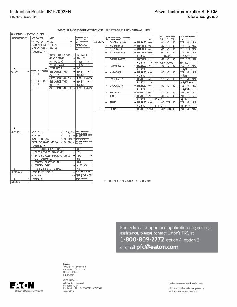
TYPICAL BLR-CM POWER FACTOR CONTROLLER SETTINGS FOR 480 V AUTOVAR UNITS
3.7
C 50
C 50 KVAR**
KVAR**
For technical support and application engineering assistance, please contact Eaton’s TRC at1-800-809-2772 option 4, option 2
or email [email protected]